xcn - richardmergethomepage x array x series... · 2002-05-08 · the xcn is an active near-field,...
TRANSCRIPT

Description
The X-Array™ product line represents im-portant advancements in concert-sound-reinforcement technology. The designgoals called for the highest acoustic out-put capability with the highest fidelity inlightweight, compact enclosures that wereeasy to array. The development began witha clean sheet of paper and took an inte-grated approach. The individual loud-speaker drivers, horns, enclosures, rigginghardware and system configurations weredesigned from the ground up specificallyfor this high-performance application.
The Xcn is an active near-field, two-way,MB/HF loudspeaker system with a rotat-able 60° x 40° coverage pattern. The high-frequency and mid-bass sections are hornloaded with one driver in each frequencyband, and the HF horn/driver combinationis mounted coaxially inside the mid-basshorn. The mid-bass and high-frequencysections are identical to that of the full-size Xn X-Array™ system. The horns anddrivers were designed as part of the Xcndevelopment and represent a step forwardin state-of-the-art loudspeaker design interms of high acoustic output with lowdistortion and low power compression.Electro-Voice engineers developed anew technology dubbed Ring-Mode
Decoupling (RMD™) to substantially im-prove clarity and intelligibility by reduc-ing both linear and nonlinear resonancemodes that color the sound.
The high-frequency driver in the Xcn isthe ND5, which is a 3.56-mm (1.4-in.) exithigh-frequency compression driver thatfeatures a powerful neodymium motorstructure that was optimized for maximumefficiency and reduced power compression.A new 76.2-mm (3.0-in.)-diameter titaniumdiaphragm assembly provides increased in-stantaneous peak output capability andreduced dome breakup. The ND5 ismounted on a 60° x 40° rotatable constant-directivity horn. This combination resultsin substantially improved vocal clarity andpresence with a smooth response through-out the vocal range up to 20,000 Hz. Thehorn and driver are nested inside the mid-bass phase plug assembly to minimize in-terference in the mid-bass band.
The mid-bass driver in the Xcn is theND12A, which is a 30.5-mm (12-in.) mid-bass driver that features a powerful newneodymium motor structure that was opti-mized for maximum horn-loaded efficiencyand reduced power compression. A newKevlar®-reinforced cone assembly pro-vides a smooth response with reducedcone break up. The ND12A is mounted ona mid-bass horn that has a coverage pat-
tern that transitions smoothly into the ro-tatable 60° x 40° high-frequency pattern.The mid-bass phase plug provides opti-mal loading for the ND12A driver, deliver-ing smooth response and extended effi-ciency up to 2,000 Hz. This combinationresults in improved vocal intelligibility andclarity with a smooth response from thelower-to-mid vocal range.
Ring-Mode Decoupling, (RMD™) is atechnique utilized and named by Electro-Voice to describe a process used to im-prove sound quality in loudspeaker sys-tems. RMD™ offers a solution to a veryfundamental problem. It has long been rec-ognized that two different loudspeakersystems can sound different even thoughthey both may be equalized to have thesame frequency response. This differenceis due to a variety of resonances, or ringmodes, that color the sound. Although thisringing may be very low in level comparedto the program material, it is still audible.The source of these resonances may bemechanical or acoustical in nature or a com-bination of both. In addition, they may belinear or nonlinear, resulting in their char-acter changing with level. Furthermore,these ring modes may be aggravated whenmultiple loudspeaker enclosures are as-sembled into arrays. The result is a colora-tion that decreases intelligibility and clar-
XcnX-Array™ Two-Way,MB/HF System• MB and HF sections are identi-
cal to Xn• Ring-Mode Decoupling (RMD™)
provides accurate transientdetail
• Near-field 60° x 40° rotatablecoverage pattern
• Neodymium ND5 HF and ND12AMB drivers
• Unique rear-hinge rigging• Enclosure shell and rigging
identical to all of the half-sizeX-Array™ systems

Xcn
Two
-Way
MB
/HF
Syst
em
Xcn Two-Way MB/HF System
2
ity with the nature of that coloration vary-ing with level. Often, the listener perceivesthat coloration as imbalance in the fre-quency response, and will attempt to elec-tronically adjust the system to restore thespectral balance. However this electronicequalization has the negative effect ofchanging the program material itself.
Ring-Mode Decoupling (RMD™) ad-dresses mechanical resonances with me-chanical solutions, and acoustical reso-nances with acoustical solutions. In theXcn development, RMD™ was applied atevery level – to the individual mid-bassand high-frequency drivers, the mid-bassand high-frequency horns, the mid-basschamber, the interaction between the mid-bass and high-frequency bands and theinteraction between multiple enclosures.
The design process included, for example,the driver diaphragm, cone, suspensionand phase-plug geometry and materials,horn geometry and materials, enclosure ge-ometry and materials, absorptive materi-als, etc. The result is a dramatic improve-ment in clarity and with a much more neu-tral sound (a lack of coloration), with theloudspeaker system maintaining its sonicintegrity from the very-lowest sound-pres-sure levels, to the very-highest sound-pres-sure levels. This means that the front-of-house engineer will not have to retune theEQ and level settings as the SPL is in-creased throughout the show. This alsomeans that the sound-system performancewill remain consistent in different array con-figurations and from venue to venue.
The X-Array™ systems utilizes a uniquerigging system. A hinge assembly is usedto link cabinets together at their rear cor-ners, while wire-rope/fitting assemblies areused at the front to adjust the relative anglebetween systems. (See the Flying the X-Array™ Systems section for more details.)
The Xcn utilizes the half-size X-Array™enclosure shell, which is identical to thatof the Xcb bass system. They have thesame footprint and rigging as the full-sizeX-Array™ systems; however, the heightof the compact systems is approximatelyhalf that of the full-size systems.
The durable Xcn enclosure is constructed
of 18-mm, 13-ply birch plywood and has awear-resistant black, textured paint finish.The system is trapezoidal, forming an
18° wedge, and includes a heavy-dutysteel grille with a water-resistant charcoal-gray foam interlining. The enclosure fea-tures vinyl bumper pads on the front cor-ners and feet on the bottom to resist wear.
A variety of accessories are available forthe X-Array™ loudspeaker systems, in-cluding rigging hardware, dollies, covers,electronic crossovers, amplifier racks andspeaker cabling. Consult the X-Array™ Ac-
cessories section for a complete listing theavailable accessories.
Applications
The X-Array™ loudspeaker systems weredesigned for optimal performance in bothconcert-sound and permanent-installationapplications where studio-monitor soundquality is required at concert-sound lev-els. The X-Array™ loudspeaker systemswork well individually, in small arrays andin large arrays. The high-acoustic outputfrom these compact, lightweight systemsprovide the highest acoustic-power-to-weight ratio, the highest acoustic-power-to-frontal-area ratio, and the highest acous-tic-power-to-bulk-volume ratio in the in-dustry. That means that X-Array™ sys-tems will be considerably smaller and lightercompared to competitive systems havingequivalent acoustic output.
The 60° x 40° coverage pattern of the Xcnmakes it ideal for sound-reinforcement ap-plications with short- to medium-throw
requirements. With its response from 125-20,000 Hz, the Xcn is recommended for mid-bass/high-frequency applications, andshould be used with an X-Array™ bassbox (like the Xb, Xcb or Xds) for full-rangeperformance. The Xcn may be used indi-vidually or in multiples to construct arrays.In addition, the Xcn may be used with theMB/HF- or LF/MB/HF X-Array™ loud-speaker systems (like the Xf, Xn or Xcn) toconstruct large full-range arrays. The Xcnenclosure is identical to that of the otherhalf-size X-Array™ systems (like the Xcb).The footprint of the half-size X-Array™enclosures is identical to that of the full-
size X-Array™ systems (like the Xn, Xfand Xb), as is the rigging hardware, mak-ing array integration easy whether flyingor stacking. The rotatable horn pattern of-fers tremendous flexibility to tailor the pat-tern to the application. For example, the60°H x 40°V orientation would be wellsuited for front-of-house, front-fill and side-fill applications while the 40°H x 60°V ori-entation would be well suited for down-fillapplications.
The Xcn is a two-way active system thatrequires an active electronic crossover.Both the Electro-Voice Dx38 and KlarkTeknik DN8000 digital crossovers are rec-ommended for signal control. (See theCrossover, Equalization and Signal De-lay Controller section.) The Electro-VoiceP3000 amplifier is recommended for pow-ering the Xcn. (See the Amplifier Recom-mendations section.)
Power-Handling Capabilities
The Xcn systems are rated as per the“ANSI/EIA RS-426-A Loudspeaker PowerRating, Full Range Test,” which uses ashaped-random-noise signal to simulatetypical music to test the mechanical andthermal capabilities of the loudspeakers.A digital crossover was used to providethe appropriate filtering and equalization.The test parameters are as follows:
High-Frequency Section
PE(MAX)
: 75 watts
Test Voltage: 30.1-volts rms
60.2-volts peak
RSR
(1.15 RE): 12.1 ohms
Mid-Bass-Frequency Section
PE(MAX)
: 300 watts
Test Voltage: 45.5-volts rms
91.0-volts peak
RSR
(1.15 RE): 6.90 ohms
Amplifier Recommendations
Power amplifiers with the following ratingsare recommended for use with the Xcnloudspeaker systems:
HF: 800 watts per channelinto 8 ohms

Xcn Two
-Way M
B/H
F System
Xcn Two-Way MB/HF System
3
93-volts rms short term
132-volts peak
MB: 800 watts per channelinto 8 ohms
93-volts rms short term
132-volts peak
Xcn loudspeakers may be paralleled withother Xcn systems as long as the amplifi-ers can drive the lower impedances. Tomaintain a sufficient damping factor withlong cable runs, amplifier loads of fourohms per channel are recommended. TheElectro-Voice P3000 amplifiers are ideal forpowering the X-Array™ systems.
Crossover, Equalization and SignalDelay Controller
The Xcn is a two-way active loudspeakersystem requiring an active crossover,equalization and signal delay controller.For basic applications, the Electro-VoiceDx38 2-in/4-out controller is recommended.For more sophisticated applications, theKlark Teknik DN8000 2-in/ 5-out controlleris recommended. Linkwitz-Riley crossoverfilters with a minimum slope of 24-dB peroctave at 125 Hz and 1,760 Hz are recom-mended. Both the Dx38 and the DN8000offer appropriate filtering, equalization andsignal delay capabilities to provide opti-mum performance of the X-Array™ loud-speaker systems. Digital parameter settingsfor both controllers are available uponrequest.
Electrical Connection and SystemWiring
Two paralleled Neutrik 8-pin Speakon®
connectors are used for electrical connec-tion to the Xcn loudspeakers with the fol-lowing pin assignments:
HF: Pins 4 Paralleled
MB: Pins 3 Paralleled
The Xcn wiring diagram is shown in Fig-ure 7. Since the connectors are paralleled,it does not matter which connector is usedas the input or output when paralleling Xcnsystems. Although Pins 1 and 2 are notused by the Xcn systems, they are paral-leled on the input panel. This allows an X-Array™ bass box (like the Xb or Xcb –
which use Pins 1 and 2, but not Pins 3 and4) to be paralleled with an Xcn, allowing alleight conductors to be used with a singlecable run to the amplifiers. Note that whenfour Xcn systems are jumped from one toanother, the amplifier home-run cable willhave four high-frequency drivers on Pins4 (for a 4-ohm load) and four mid-bass driv-ers on Pins 3 (for a 4-ohm load).
Flying the X-Array™ Systems
The X-Array™ loudspeaker systems allutilize the same rigging hardware and havethe same structural strength ratings. Thus,different systems may be mixed in an arrayto achieve the best acoustic results. Therigging system allows for the smallest pos-sible spacing between adjacent enclosures,and utilizes quick-release rigging fittingsfor fast installation and tear down.
When flown, the X-Array™ enclosures arelinked together by two removable hingeson the rear of the enclosures at the top andbottom. This arrangement enables the en-closures to pivot vertically from the rearcorners. The relative vertical angle betweenadjacent enclosures is adjustable and setby two removable rigging straps on thefront of the enclosures at the top and bot-tom. Both the rear rigging hinges and thefront rigging straps are installed when en-closures are sitting on top of one another.For ease of installation of the hinges andstraps, the enclosures self align using feetand cups mounted on the top and bottomof the enclosures. The relative horizontalangle between adjacent columns of loud-speakers is set by adjustable grids at thetop of the array (or by custom-building at-tachment supports in permanent-installa-tion applications where grids are not used).
The removable proprietary rear rigginghinges utilize all-steel construction and aresecured into a proprietary track assemblyon the enclosure (similar to the heavy-dutyaircraft L-track). The aluminum track is ex-truded as a single-piece track/angle-bracketassembly and ties into the top, bottom andrear of the enclosure. Metal bars inside theenclosure tie the top and bottom track/angle-bracket assemblies together, minimiz-ing the load applied to the wooden enclo-
sure. The rear extrusion will accommodatethe New Haven 32102-2 aircraft-typedouble-stud locking fitting instead of thehinge for applications requiring a lowerstrength rating.
The removable front strap assemblies uti-lize all-steel New Haven 32102-2 aircraft-type double-stud locking fittings and wirerope, and are secured into another propri-etary track similar to the heavy-duty air-craft L-track. The track is extruded as asingle-piece track/angle-bracket assemblythat ties into the front and side of the en-closure. The track/angle-bracket assemblyextends from the top to the bottom of theenclosure, eliminating the load applied tothe wooden enclosure.
A complete line of flying-hardware acces-sories is available for the X-Array™ loud-speaker systems including a grid, rigginghinges and rigging straps. The variety ofrigging hinges and front rigging strapsavailable include those for linking two en-closures together, securing the top enclo-sure in a column to a grid, and for pickingup the top enclosure in a column without agrid. Consult the X-Array™ Accessoriessection for a complete listing the availablerigging accessories.
The total weight of a column of X-Array™loudspeaker systems that may be sup-ported by the X-Array™ rigging systemvaries from 454-726 kg (1,000-1,600 lb) de-pending on the rigging configuration de-tails. An X-Array™ Flying Manual isavailable from Electro-Voice and is includedwith each X-Array™ system shipment. Themanual should be consulted for completestructural specifications and detailed in-structions for safely suspending and us-ing the X-Array™ systems.
Field Replacement
Normal service for the Xcn requires only a#2 Phillips screwdriver and a 3/16-inch hex-key wrench. The drivers may be accessedas follows:
HF: First remove the grille, then removethe screws securing the front flange of thehigh-frequency horn. Lift the horn anddriver out of the shroud assembly. In theevent of failure, the diaphragm assembly

Xcn
Two
-Way
MB
/HF
Syst
em
Xcn Two-Way MB/HF System
4
Xcn Two-Way, MB/HF System
can be replaced with the driver attached tothe horn.
MB: Remove the screws securing thehatch on the back of the enclosure and liftthe hatch out. Remove the screws secur-ing the 12-inch driver and lift the driver outof the enclosure. In the event of failure,the entire driver must be replaced.
The following service parts are availablefrom the service department in Buchanan,Michigan USA:
HF: #84423-XX 16-ohm ND5-16
diaphragm kit
#827-2973 ND5-16 complete driver
MB: #812-2858 ND12A complete driver
LF: #818-2883 EVX-180B complete driver
The complete drivers are available only forrepair replacement and are not availablefor general sale.
Architects’ and Engineers’Specifications
The loudspeaker system shall be a three-way, active, coaxial, MB/HF system with afrequency response from 125-20,000 Hz withcrossover frequencies at 125 and 1,760 Hzand a rotatable 60° x 40° constant-directiv-ity coverage pattern. The loudspeaker sys-tem shall have a high-frequency compres-sion driver mounted on a 60° x 40° constant-directivity horn, and shall have a 16-ohm,76.2-mm (3-in.) diameter voice coil, a76.2-mm (3-in.) titanium dome, a 35.6-mm(1.4-in.) exit, a neodymium magnetic motorstructure, and a 75-watt power rating.The loudspeaker system also shall havea 305-mm (12-in.) mid-bass drivermounted on a mid-bass horn, and shallhave a 16-ohm, 63.5-mm (2.5-in.) diametervoice coil, a neodymium magnetic motorstructure, and a 300-watt power rating. Theloudspeaker shall have a rigging systemenabling a column of loudspeakers to behinged at their back corners with relativedownward angles set by adjustable riggingstraps at the front. The enclosure shall beconstructed of 18-mm thick, 13-ply birchplywood, and shall be trapezoidal formingan 18° wedge, and be 596 mm (23.46 in.)high, 584 mm (23.00 in.) wide at the front,354 mm (13.93 in.) wide at the back and
759 mm (29.88 in.) deep and shall weigh60.8 kg (134 lb). The loudspeaker sys-tem shall be the Electro-Voice Xcn.
Rigging Accessories
Grid: This ATM Fly-Ware™ “T”-shaped,all-steel-construction grid was specificallydesigned as a single column of X-Array™systems. Multiple grids can be linked to-gether with couplers on front and back re-tractable arms, the position of which setsthe splay angle between adjacent columns.Part number MEGS-4000-T. ATMFly-ware™, 2100 S. Wilmington Ave.,Carson, CA 90810 USA, 310/834-5914
Xrhg Grid Hinge: Two Xrhg grid rigginghinges are used to attach the rear of thetop enclosure in a column to the rear of anX-Array™ compatible grid. Each hinge con-sists of two precision-machined steel rig-ging-track fittings connected by an alloy-steel chain. Part number 510-2999. Electro-Voice, 600 Cecil St., Buchanan, MI 49107USA, 616/695-6831 or 800/234-6831
Xrhp Pickup Hinge: Two Xrhp pickuprigging hinges are used to create customrigging assemblies to attach to the rear ofthe top enclosure in a column when anATM grid is not used. Each hinge con-sists of one precision-machined steel rig-ging-track fitting with an alloy-steel chain.Part number 510-3000. Electro-Voice, 600Cecil St., Buchanan, MI 49107 USA,616/695-6831 or 800/234-6831
Xrhl Linking Hinge: Two Xrhl linkingrigging hinges are used to link two enclo-sures together at the rear. Each hinge con-sists of two precision-machined steel rig-ging-track fittings connected by a heavy-duty steel hinge. Part number 510-2998.Electro-Voice, 600 Cecil St., Buchanan, MI49107 USA, 616/695-6831 or 800/234-6831Xrsl Long Rigging Steel Straps: Two Xrsllong rigging straps are used at the front oftwo enclosures to adjust their relative ver-tical angles. The Xrsl may also be used toattach the front of the top enclosure to theATM grid when upward angles are not re-quired. Each all-steel strap consists of twoNew Haven NH32102-2 double-stud fit-tings connected by black plastic-coated
wire rope. Sound Manufacturing Inc., 3336Primera Ave., Hollywood, CA 90068 USA,213/850-5042 or ATM Fly-ware™, 2100 S.Wilmington Ave., Carson, CA 90810 USA,310/834-5914
Xrss Short Rigging Steel Straps: TwoXrss short rigging straps are used to at-tach the front of the top enclosure to theATM grid. The Xrss may also be used atthe front of two enclosures when a limitedrange of vertical angles are required. Theall-steel Xrss utilizes the same construc-tion as the Xrsl. Sound Manufacturing Inc.,3336 Primera Ave., Hollywood, CA 90068USA, 213/850-5042 or ATM Fly-ware™,2100 S. Wilmington Ave., Carson, CA 90810USA, 310/834-5914
General Rigging Supplies: A wide vari-ety of standard and specialty rigging hard-ware components for both touring and per-manent-installation applications is avail-able. Sound Manufacturing Inc., 3336Primera Ave., Hollywood, CA 90068 USA,213/850-5042 or ATM Fly-ware™, 2100 S.Wilmington Ave., Carson, CA 90810 USA,310/834-5914
Electronic Accessories
Klark Teknik DN8000 Digital Control-ler: The DN8000 digital electronic loud-speaker controller has a two-in/five-out ar-chitecture, with each output having pro-grammable high-pass and low-pass filters,four-band equalization, signal delay, com-pressor- limiter-and noise-gate functions.Program parameters for optimal perfor-mance of the X-Array™ systems are avail-able. Klark Teknik, Klark Industrial Park,Walter Nash Road, Kidderminster,Worcestershire DY11 7HJ England, 44-156-274-1515
Electro-Voice Dx38 Digital Controller:The Dx38 digital electronic loudspeakercontroller has a two-in/four-out architec-ture, with each output having program-mable high-pass and low-pass filters, four-band equalization, signal delay compres-sor and limiter functions. Program param-eters for optimal performance of theX-Array™ systems are available. Electro-Voice, 600 Cecil St., Buchanan, MI 49107USA, 616/695-6831

Xcn Two
-Way M
B/H
F System
Xcn Two-Way MB/HF System
5
Xcn Two-Way, MB/HF System
Electro-Voice P3000 Power Amplifiers:The stereo P3000 power amplifiers are ratedat 800 watts into 8 ohms, or 93-volts rmsshort term. The amplifiers are 3-U high andweigh 28 kg (62 lb) each. Electro-Voice, 600Cecil St., Buchanan, MI 49107 USA,616/695-6831
X-Array™ Amplifier Racks: These 16-Uracks will hold four Electro-Voice P3000power amplifiers, one Klark Teknik DN8000digital controller, 1-U light module, and a2-U multipin patch panel. The aluminum-frame/wood-panel racks are vibration-iso-lation mounted on heavy-duty wheelboards and come prewired for AC power,audio and control signal sends and Neu-trik® Speakon speaker connectors. dbSound, L.P., 1219 Rand Road, Des Plaines,IL 60016 USA, 847/299-0357
X-Array™ Speaker Cables: Eight con-ductor cable with four #11 AWG conduc-tors and four #13 AWG connectors. Thelarger conductors are used in the LF bandsfor increased damping factor. Lengthsmade to order. Standard terminations areNeutrik Speakon™ NL8FC connectorswired to X-Array™ standards; however,custom terminations are available. Enter-tainment Technology Cable, 1247 RandRoad, Des Plaines, IL 60016 USA,
800/529-6312
Miscellaneous Accessories
X-Array™ Loudspeaker Covers: Heavy-duty covers are available for the X-Array™speakers. These covers wrap around theenclosures, while sitting on a dolly, andVelcro together at the back for fast instal-lation and removal. db Sound, L.P., 1219Rand Road, Des Plaines, IL 60016 USA,847/299-0357
X-Array™ Dolly Boards: Double-widedolly built to hold four X-Array™ loud-speakers, two wide by two high. Thedouble-thick 18-mm birch-plywood con-struction includes cutouts and keys forloudspeaker enclosure shape and align-ment feet. The dolly boards are paintedblack and utilize four extra-heavy-duty4-inch x 2-inch casters. Custom-designeddolly boards are also available to meet spe-
cific requirements. R&R Cases and Cabi-nets, 1217 Rand Road, Des Plaines, IL 60016USA, 847/299-8100
Racks and Road Cases: A variety of gen-eral purpose, custom racks and hard-shellroad cases are available for touring or per-manent-installation applications. R&RCases and Cabinets, 1217 Rand Road, DesPlaines, IL 60016 USA, 847/299-8100
Limited Warranty
Electro-Voice products are guaranteedagainst malfunction due to defects in ma-terials or workmanship for a specified pe-riod, as noted in the individual product-line statement(s) below, or in the individualproduct data sheet or owner’s manual, be-ginning with the date of original purchase.If such malfunction occurs during thespecified period, the product will be re-paired or replaced (at our option) withoutcharge. The product will be returned to thecustomer prepaid. Exclusions and Limita-tions: The Limited Warranty does not ap-ply to: (a) exterior finish or appearance;(b) certain specific items described in theindividual product-line statement(s) below,or in the individual product data sheet orowner’s manual; (c) malfunction resultingfrom use or operation of the product otherthan as specified in the product data sheetor owner’s manual; (d) malfunction result-ing from misuse or abuse of the product;or (e) malfunction occurring at any timeafter repairs have been made to the prod-uct by anyone other than Electro-VoiceService or any of its authorized service rep-resentatives. Obtaining Warranty Ser-vice: To obtain warranty service, a cus-tomer must deliver the product, prepaid, toElectro-Voice Service or any of its autho-rized service representatives together withproof of purchase of the product in theform of a bill of sale or receipted invoice. Alist of authorized service representativesis available from Electro-Voice Service at600 Cecil Street, Buchanan, MI 49107(800/234-6831 or FAX 616/695-4743). Inci-dental and Consequential Damages Ex-cluded: Product repair or replacement andreturn to the customer are the only rem-edies provided to the customer. Electro-
Voice shall not be liable for any incidentalor consequential damages including, with-out limitation, injury to persons or prop-erty or loss of use. Some states do notallow the exclusion or limitation of inciden-tal or consequential damages so the abovelimitation or exclusion may not apply toyou. Other Rights: This warranty givesyou specific legal rights, and you may alsohave other rights which vary from stateto state.
Electro-Voice Speakers and Speaker Sys-tems are guaranteed against malfunctiondue to defects in materials or workman-ship for a period of five (5) years from thedate of original purchase. The LimitedWarranty does not apply to burned voicecoils or malfunctions such as cone and/orcoil damage resulting from improperly de-signed enclosures. Electro-Voice activeelectronics associated with the speakersystems are guaranteed for three (3) yearsfrom the date of original purchase. Addi-tional details are included in the UniformLimited Warranty statement.
Electro-Voice Accessories are guaranteedagainst malfunction due to defects in ma-terials or workmanship for a period of one(1) year from the date of original purchase.Additional details are included in the Uni-form Limited Warranty statement.
Electro-Voice Flying Hardware (includingenclosure-mounted hardware and riggingsaccessories) is guaranteed against mal-function due to defects in materials orworkmanship for a period of one (1) yearfrom the date of original purchase. Addi-tional details are included in the UniformLimited Warranty statement.
For warranty repair or service informa-tion, contact the service repair departmentat: 616/695-6831 or 800/685-2606.
For technical assistance, contact Techni-cal Support at 800/234-6831 or616/695-6831, M-F, 8:00 a.m. to 5:00 p.m.Eastern Standard Time.
Specifications subject to change withoutnotice.

Xcn
Two
-Way
MB
/HF
Syst
em
Xcn Two-Way MB/HF System
6
VerticalHorizontal
5 dB per divisionFigure 1 — Polar ResponseThe directional response of the Xcn was measured in an anechoic environment at adistance of 6.1 m (20 ft.) using 1/3-octave-filtered pink noise with a full spherical measure-ment system. The Klark Teknik DN8000 digital electronic unit was used to provide thenecessary crossover filters, equalization and time delay. The polar response of the loud-speaker system at selected 1/3-octave frequencies is shown. The selected frequencies arerepresentative of the polar response of the system.
160 Hz 250 Hz200 Hz
315 Hz 400 Hz
630 Hz 1000 Hz800 Hz
500 Hz

Xcn Two
-Way M
B/H
F System
Xcn Two-Way MB/HF System
7
VerticalHorizontal
5 dB per division
1600 Hz 2000 Hz1250 Hz
10 kHz 12.5 kHz 16 kHz
2500 Hz 3.15 kHz 4 kHz
5 kHz 6.3 kHz 8 kHz
Xcn
Two
-Way
MB
/HF
Syst
em
Xcn Two-Way MB/HF System
8
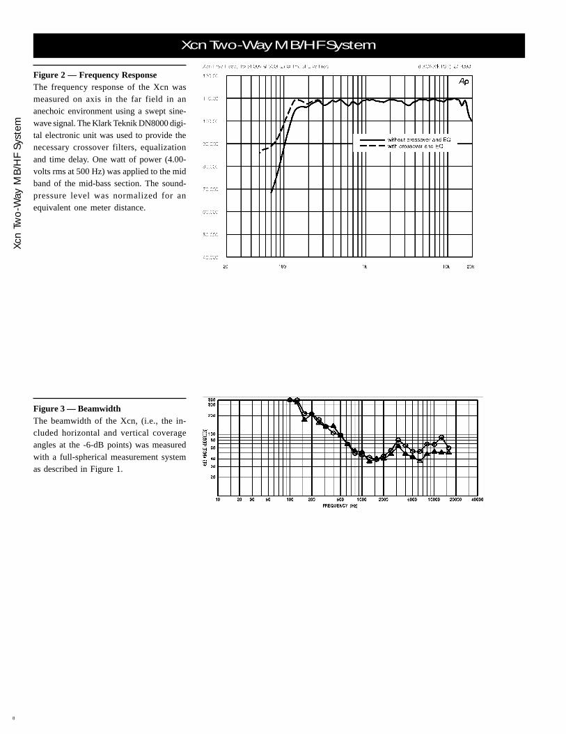
Figure 3 — BeamwidthThe beamwidth of the Xcn, (i.e., the in-cluded horizontal and vertical coverageangles at the -6-dB points) was measuredwith a full-spherical measurement systemas described in Figure 1.
Figure 2 — Frequency ResponseThe frequency response of the Xcn wasmeasured on axis in the far field in ananechoic environment using a swept sine-wave signal. The Klark Teknik DN8000 digi-tal electronic unit was used to provide thenecessary crossover filters, equalizationand time delay. One watt of power (4.00-volts rms at 500 Hz) was applied to the midband of the mid-bass section. The sound-pressure level was normalized for anequivalent one meter distance.

Xcn Two
-Way M
B/H
F System
Xcn Two-Way MB/HF System
9
Figure 5 — DistortionDistortion for the Xcn was measured onaxis in the far field in an anechoic environ-ment with an input signal that would resultin a sound-pressure level of 115 dB at onemeter. The Klark Teknik DN8000 digitalelectronic unit was used to provide the nec-essary crossover filters, equalization andtime delay. A frequency spectrum typicalof close-miked rock music was employed.The sound pressure level was normalizedfor an equivalent one-meter distance. Plotsof second and third harmonic distortionare shown referenced to the fundamental.
Figure 4 — DirectivityThe directivity index, D
i, and directivity fac-
tor, R , of the Xcn were measured with a
full- spherical measurement system as de-scribed in Figure 1.
Figure 6 — ImpedanceThe impedance of each frequency band ofthe Xcn was measured in an anechoic en-vironment.

Xcn
Two
-Way
MB
/HF
Syst
em
Xcn Two-Way MB/HF System
10
Figure 7—Wiring DiagramThe wiring diagram of each frequency bandof the Xcn is shown.
Figure 8—Dimensions
BLACK SPEAKER TERMINAL IS "-"
HF:
MB:
PINS 1 & 2 PARALLELED
PINS 4 PARALLELED
PINS 3 PARALLELED
RED SPEAKER TERMINAL IS "+"
BLACK
BLUE
BLACK
RED
BLACK
RED
BLACK
WHITE
3 -
1 -
1+
2 -
2+
4+
4 -
3+
1 -BLACK
RED1+
BLACK
RED
BLACK
BLUE
BLACK
WHITE
PAR
ALL
ELE
D C
ON
NE
CT
OR
S
4+
4 -
3+
3 -
2 -
2+
WHITE
BLUE
BLACK
BLACK +
_
+
_
16 OHMS NOMINAL
MB
6.0 OHMS DC
HF16 OHMS NOMINAL
10.5 OHMS DC
353.8 mm(13.93 in.)
733.2 mm(28.87 in.)
758.8 mm(29.88 in.)
584.2 mm(23.00 in.)
595.9 mm(23.46 in.)
9.0°TYP.
WEIGHT: 60.8 kg(134 lb)

Xcn Two
-Way M
B/H
F System
Xcn Two-Way MB/HF System
11
Specifications
Frequency Response (measured in farfield, calculated to one meter on axis,swept sine wave, one watt into MBsection–4.00 V at 500 Hz, anechoicenvironment; see Figure 2):
125-20,000 HzCrossover Frequency:
125/1,760 HzEfficiency, Mid Band MB/HF:
25/25 %Maximum Long-Term-Average Power-Handling Capacity (per ANSI/EIA RS-426A 1980), MB/HF:
300/75 wattsMaximum Long-Term AverageMid-Band Acoustic Output, MB/HF:
75/19 acoustic wattsSensitivity (SPL at one meter, indicatedinput power, anechoic environment,average level), MB/HF,
1/1 watt:110.0/112.0 dB
300/60 watts:134.8/130.8 dB
Beamwidth (angle included by 6-dB-down points on polar responses, indi-cated one-third-octave bands of pinknoise; see Figures 1 and 3),
Horizontal, 800-16,000 Hz:60° (+30°, -18°)
Vertical, 800-16,000 Hz:40° (+24°, -4°)
Directivity Factor, R (Q),800-16,000 Hz
Average (see Figure 4):22.1 (+12.5, -7.6)
Directivity Index, Di, 800-16,000 Hz
Average (see Figure 4):13.4 dB (+2.0 dB, -1.8 dB)
Distortion (115 dB SPL at one meter,shaped spectrum; see Figure 5),
Second Harmonic,200 Hz:
1.9%500 Hz:
0.7%2,000 Hz:
1.2%5,000 Hz:
1.1%Third Harmonic,
200 Hz:0.3%
500 Hz:0.2%
2,000 Hz:< 0.1%
5,000 Hz:< 0.1%
Transducer Complement,HF:
ND5-16 compression driver,HP-type 60° x 40° horn
MB:ND12A 12-in. mid-bass driver,60° x 40° horn
Impedance (see Figure 6),Nominal, MB/HF:
16/16 ohmsMinimum, MB.HF:
9.9/12.9 ohms
Input Connections:Two Neutrik NL8MPR Speakon®
connectors paralleledRecommended Amplifier Power, Rating:
HF:800 watts per channel @ 8 ohms(93-volts rms short term)
MB:800 watts per channel @ 8 ohms(93-volts rms short term)
Enclosure Construction,Enclosure Shell:
18-mm, 13-ply birch plywoodFinish:
Black textured paintGrille:
Powder-coated steel with foamRigging:
Proprietary hinge system at rear. Heavy-duty L-track on front which acceptsNew Haven NH32102-2 double-studfittings
Dimensions,Height:
595.9 mm (23.46 in.)Width (front):
584.2 mm (23.00 in.)Width (back):
353.8 mm (13.93 in.)Depth:
758.8 mm (29.88 in.)Angle:
18° wedgeNet Weight:
60.8 kg (134 lb)Shipping Weight:
64.9 kg (143 lb)

Xcn
Two
-Way
MB
/HF
Syst
em
Xcn Two-Way MB/HF System
12
600 Cecil Street, Buchanan, MI 49107616/695-6831, 616/695-1304 Fax
Part Number 534834 Rev.B—9934SPEAKERS—X-ArrayTM ©Telex Communications, Inc., 1999 • Litho in U.S.A.