xcel energy operating companies interconnection … · transmission system guideline xcel energy...
TRANSCRIPT
Transmission System Guideline
Xcel Energy Operating Companies
Interconnection Guidelines For Transmission Interconnected Producer-Owned Generation 20 MW or less
Version: 4.0
File Name : XEL-POL-TransmissionInterconnectionGuidelineLess20MW.doc Page 1 of 71
1.0 PURPOSE
This guideline describes the requirements for connecting new generation of 20 megawatts (MW) or less to an electric transmission line or a substation owned and operated by Public Service Company of Colorado (PSCo)
Note: NSP and NSPW are members of the Midcontinent ISO, and interconnection of new generation is subject to the Midcontinent ISO Tariff on file with FERC. SPS is a member of the Southwest Power Pool, and interconnection of new generation is subject to the SPP Tariff. Interconnection of new generation to PSCo is subject to the Xcel Energy Operating Companies Tariff. The applicable Tariff should be reviewed in addition to these Guidelines.
2.0 APPLICABILITY AND RESPONSIBILITIES
Xcel Energy Services Inc., the service company for the Xcel Energy Inc. holding company system
Xcel Energy Operating Companies
3.0 APPROVERS
Name Title
Anthony T. Jandro Director, Transmission Portfolio Delivery
Ian R. Benson Director, Transmission Planning & Business Relations
Roger D. Hargreaves Director, System Operations
Allen L. Bellinghausen Director, Substation, Operations & Maint.
Byron R. Craig Director, Subs & Trans Engineering and Design
4.0 VERSION HISTORY
Date Version Number
Supersedes Change
08/31/2014 2.0 N/A Initial ProjectWise Document. Original document version is 1.0—ProjectWise version
08/31/2015 3.0 2.0 Annual review and update
8/31/2016 4.0 3.0 Annual review and update
Transmission System Guideline
Xcel Energy Operating Companies
Interconnection Guidelines For Transmission Interconnected Producer-Owned Generation 20 MW or less
Version: 4.0
File Name : XEL-POL-TransmissionInterconnectionGuidelineLess20MW.doc Page 2 of 71
TABLE OF CONTENTS
I. INTRODUCTION AND GENERAL POLICY 6
A. INTRODUCTION .................................................................................................................... 6
B. THE XCEL ENERGY SYSTEMS .................................................................................................. 8
C. GUIDELINE AUTHORITY ....................................................................................................... 10
D. GUIDELINE OBJECTIVES AND LIMITATIONS .......................................................................... 11
E. INTERCONNECTION PROCESS .............................................................................................. 12
F. FINANCIAL OBLIGATION OF THE PRODUCER ......................................................................... 12
G. OWNERSHIP, OPERATION .................................................................................................... 13
H. OPERATION SUBJECT TO BALANCING AUTHORITY/TRANSMISSION OPERATIOR...................... 14
I. GENERATOR CERTIFICATION AND ACCREDITATION .............................................................. 14
1. MRO Reliability Region Generation Units ...................................................... 14 2. SPP Reliability Region Generation Units ....................................................... 16
3. WECC Reliability Region Generation Units ................................................... 16
J. NERC AND REGIONAL ENTITY POLICIES AND STANDARDS COMPLIANCE ................................... 16
K. REGULATORY APPROVALS AND PERMITS ................................................................................ 16
II. INTERCONNECTION TECHNICAL REQUIREMENTS 18
A. GENERATION INTERCONNECTION SUBSTATION CONFIGURATION ......................................... 18
B. MODELING INFORMATION ................................................................................................... 18
C. SEPARATE SYSTEMS ............................................................................................................ 19
D. PARALLEL OPERATION ......................................................................................................... 19
E. PROTECTIVE DEVICES ......................................................................................................... 19
F. INTERFERENCE ................................................................................................................... 20
G. VOLTAGE, HARMONICS, AND FLICKER .................................................................................. 20
1. Steady State Voltage Range ......................................................................... 21 2. Dynamic Voltage Range ................................................................................ 21
3. Flicker and other voltage variations ................................................................ 22 4. Harmonics ...................................................................................................... 22
H. FREQUENCY AND FREQUENCY CONTROL .............................................................................. 23
1. Governor Operation ....................................................................................... 23 2. MRO REGION OVER/UNDER-FREQUENCY GENERATION TRIPPING .... 23 3. SPP REGION OVER/UNDER-FREQUENCY GENERATOR TRIPPING ...... 24
Transmission System Guideline
Xcel Energy Operating Companies
Interconnection Guidelines For Transmission Interconnected Producer-Owned Generation 20 MW or less
Version: 4.0
File Name : XEL-POL-TransmissionInterconnectionGuidelineLess20MW.doc Page 3 of 71
.............................................................................................................. 24 4. WECC REGION OVER/UNDER-FREQUENCY GENERATOR TRIPPING ... 25
I. GENERATOR REACTIVE CAPABILITY ..................................................................................... 26
1. INDUCTION GENERATORS AND INVERTERS ........................................... 26
2. MINIMUM POWER FACTOR REQUIREMENTS........................................... 26
3. VOLTAGE CONTROL BY GENERATION RESOURCES ............................. 27
4. GENERATOR TRANSFORMER SPECIFICATIONS ..................................... 27 5. GENERATOR CAPABILITY CURVES .......................................................... 27
J. POWER SYSTEM STABILIZERS GENERATOR CAPABILITY CURVES ........................................... 28
1. MRO POWER SYSTEM STABILIZERS ........................................................ 28
2. WECC POWER SYSTEM STABILIZERS ...................................................... 30 3. SPP POWER SYSTEM STABILIZERS ......................................................... 31
K. FAULT CURRENT ................................................................................................................. 31
L. SYSTEM RESTORATION AND BLACK START CAPABILITY ......................................................... 31
M. DISCONNECT DEVICE/POINT OF DEMARCATION ................................................................... 32
N. EFFECTIVE GROUNDING ...................................................................................................... 32
III. EQUIPMENT, PROTECTION AND CONTROL REQUIREMENTS 33
A. FAULT CLEARING ................................................................................................................. 33
B. UTILITY GRADE RELAYS ....................................................................................................... 33
C. MINIMUM PROTECTION REQUIREMENTS .............................................................................. 34
D. REDUNDANT/BACKUP PROTECTION ...................................................................................... 34
E. SYNCHRONIZATION OF GENERATION ................................................................................... 35
1. SYNC-CHECK RELAYS ................................................................................ 35 2. INDUCTION GENERATOR SYNCHRONIZING ............................................ 35
F. STATION POWER/STATION SERVICES ................................................................................... 35
G. GROUNDING SYSTEM .......................................................................................................... 36
H. COMMUNICATION CHANNEL (S) ........................................................................................... 36
I. METERING AND TELEMETRY REVENUE METERING ................................................................. 36
1. PRODUCER FACILITY NET GENERATOR OUTPUT TELEMETRY AND CONTROL ............................................................................................................. 36
J. SUPERVISORY CONTROL AND DATA ACQUISITION (SCADA) .................................................. 37
K. VOLTAGE AND BIL VALUES ................................................................................................... 37
Voltage and BIL levels currently in use in TYPICAL Xcel Energy Substations: 38
IV. ALTERNATIVE ENERGY INTERCONNECTIONS 39
Transmission System Guideline
Xcel Energy Operating Companies
Interconnection Guidelines For Transmission Interconnected Producer-Owned Generation 20 MW or less
Version: 4.0
File Name : XEL-POL-TransmissionInterconnectionGuidelineLess20MW.doc Page 4 of 71
A. INVERTER CONNECTED GENERATION ..................................................................................... 39
B. WIND ENERGY GENERATION.................................................................................................. 39
V. ACCEPTANCE TESTING AND INSPECTION REQUIREMENTS 40
A. GENERAL ............................................................................................................................ 40
B. DEMONSTRATION................................................................................................................ 41
1. CONSTRUCTION TESTING DOCUMENTATION REVIEW .......................... 41 2. DEMONSTRATION TESTS ........................................................................... 42 3. POST IN-SERVICE TESTS ........................................................................... 42
C. FUTURE CHANGES IN REQUIREMENTS .................................................................................. 43
D. PERFORMANCE OF TESTS .................................................................................................... 43
E. TESTING EQUIPMENT .......................................................................................................... 43
F. XCEL ENERGY SUPPLIED EQUIPMENT ................................................................................... 43
G. FINAL DESIGN/AS-BUILT DOCUMENTS .................................................................................. 44
H. GENERATOR PARAMETER DATA ............................................................................................ 44
1. SPP AND MRO.............................................................................................. 44
2. WECC ............................................................................................................ 44
VI. OPERATION AND MAINTENANCE GUIDELINES 46
A. NORMAL CONDITIONS ......................................................................................................... 46
B. ABNORMAL CONDITIONS ..................................................................................................... 46
C. ENERGIZATION OF XCEL ENERGY EQUIPMENT BY THE PRODUCER ......................................... 47
D. DISCONTINUATION OF OPERATION ...................................................................................... 47
E. MAINTENANCE NOTIFICATION ............................................................................................. 47
F. MAINTENANCE .................................................................................................................... 48
G. DESIGN CHANGES AFTER COMMERCIAL OPERATION ............................................................. 48
H. OPERATING DATA SUBMITTALS............................................................................................ 48
I. OPERATIONAL LOG .............................................................................................................. 48
J. COMMUNICATION WITH XCEL ENERGY OPERATIONS ............................................................ 49
VII. GLOSSARY 50
VIII. REFERENCES 58
APPENDIX A: TYPICAL INTERCONNECTION DIAGRAM 60
APPENDIX B: XCEL ENERGY METERING AND TELEMETRY REQUIREMENTS 61
1. GENERAL ............................................................................................................................ 61

Transmission System Guideline
Xcel Energy Operating Companies
Interconnection Guidelines For Transmission Interconnected Producer-Owned Generation 20 MW or less
Version: 4.0
File Name : XEL-POL-TransmissionInterconnectionGuidelineLess20MW.doc Page 5 of 71
2. METERING ACCURACY, TESTING, AND REPAIR ...................................................................... 61
A. Metering Accuracy – REVENUE METERING .............................. 61
b. Periodic Testing............................................................................ 62 c. Meter and Telemetry Equipment Repair ....................................... 62
3. METERING AND TELEMETRY FUNCTION REQUIREMENTS ....................................................... 62
A. Measured Values and Metering Required For Generating Stations With A Net Output Capacity Greater Than Or Equal to 20 MW .............................. 63 B. METERING CONFIGURATION ................................................... 63
C. Energy Losses ............................................................................. 65 D. Meter Reading .............................................................................. 65
4. VOICE DISPATCH CIRCUIT ................................................................................................... 66
5. PRODUCER FACILITY NET GENERATION OUTPUT TELEMETRY AND CONTROL ......................... 66
A. Generation Telemetering .............................................................. 66 B. Xcel Energy required telemetry points .......................................... 66
C. LOAD CONTROL/RELAYING/COMMUNICATION CABINETS REQUIREMENTS ................................................................................. 68
1. FAULT CLEARING REQUIREMENTS .......................................................................................... 69
2. AUTOMATIC RE-CLOSING ....................................................................................................... 69
APPENDIX C – ADDITIONAL COLLECTOR SYSTEM CONNECTION REQUIREMENTS 67
1. FAULT CLEARING REQUIREMENTS....................................................................................67 2. AUTOMATIC RE-CLOSING.................................................................................................67 3. INTERCONNECTION CONFIGURATION..............................................................................67
Transmission System Guideline
Xcel Energy Operating Companies
Interconnection Guidelines For Transmission Interconnected Producer-Owned Generation 20 MW or less
Version: 4.0
File Name : XEL-POL-TransmissionInterconnectionGuidelineLess20MW.doc Page 6 of 71
I. INTRODUCTION AND GENERAL POLICY
A. INTRODUCTION
The Interconnection Guidelines for Transmission Interconnected Producer-Owned Generation (Guidelines)
describe the requirements for connecting new generation of 20 megawatts (MW) or less to an electric transmission system owned and operated by any of the following Xcel Energy operating companies: Public
Service Company of Colorado (PSCo), Southwestern Public Service Company (SPS), or Northern States Power
Company (Minnesota) or Northern States Power Company (Wisconsin) (jointly NSP). For the balance of this document, the Xcel Energy operating companies will be jointly referred to as Xcel Energy or the Xcel Energy
Operating Companies.
One purpose of these Interconnection Guidelines is to implement the final Standardization of Small Generation Interconnection Agreements and Procedures Rules (Final Rules) adopted by the Federal Energy Regulatory
Commission (FERC) on May 12, 2006 in FERC Order No. 2006.1 The Final Rules require all FERC-jurisdictional
electric utilities, including the Xcel Energy Operating Companies, to use standardized generation interconnection procedures and agreements for all pending or new requests to interconnect a generator 20 MW or less at
transmission voltage, subject to certain regional differences.2
The Final Rules establish a pro forma Small Generation Interconnection Procedure (SGIP) and Small Generation
Interconnection Agreement (SGIA). The SGIP and SGIA will be incorporated in the Open Access Transmission Tariffs (OATTs) applicable to each Xcel Energy Operating Company (see below). Another purpose of these
Guidelines is to document the detailed technical requirements for interconnection not included in the SGIP or SGIA, as allowed by the Final Rules. To the extent there is a conflict between these Guidelines and the
applicable OATT, the applicable OATT will control unless FERC has accepted the Xcel Energy Guideline as
consistent with the Final Rules.
1 Standardization of Small Generation Interconnection Agreements and Procedures, Order No. 2006, Fed.
Reg. Vol. 70, No. 34,189 (June 13, 2005); FERC 61, 220 (2005) or latest version.
2 These Interconnection Standards thus do not apply to generation interconnections to the Distribution
system of an Xcel Energy Operating Company or to new generators sized at more than 20 MW connecting at Transmission voltage. Please contact Xcel Energy for information regarding the processes for Distribution small
generator interconnections. Contact personnel are listed in Section II. In addition, various generation units were connected to the Xcel Energy transmission systems prior to
publication of these Guidelines and the Final Rules. These were installed under prior guidelines published by
New Century Energies, Inc. or Northern States Power Company. In most cases, the system, regulatory, or safety requirements have not changed sufficiently to require these units to update their interconnection or
generation to comply specifically with this document. In some cases, compliance with certain updated requirements may be required. These will be handled on a case-by-case basis.
Transmission System Guideline
Xcel Energy Operating Companies
Interconnection Guidelines For Transmission Interconnected Producer-Owned Generation 20 MW or less
Version: 4.0
File Name : XEL-POL-TransmissionInterconnectionGuidelineLess20MW.doc Page 7 of 71
These Guidelines should thus be considered a "User's Guide" to the interconnection process for generators and
Xcel Energy employees under the Final Rules. To the extent possible, the Guidelines provide a universal set of requirements for all Xcel Energy Operating Company transmission systems. However, there are some technical
requirements specific to a state, Xcel Energy operating company or North American Electric Reliability
Corporation (NERC) Regional Region, as allowed by the Final Rules. The specific requirements are discussed in more detail below, where applicable. Each such requirement is labeled with the Operating Company, RTO, or
Reliability Region to which it applies.
In this document, certain words and abbreviations are identified as having specific meanings. These words and abbreviations are given in bold face type when initially defined. These words and abbreviations can also be
found in the GLOSSARY section of this document.
For example, for purposes of these Guidelines, the term Producer will be used to refer to transmission
connected co-generators, qualifying facilities (QFs), independent power producers (IPPs) small power producers, non-utility generators (NUGs), and Producer-owned generators. To the extent any of the Xcel
Energy operating companies construct and own generation, and propose to interconnect to the Xcel Energy
transmission system, it will also be considered a Producer with regards to the new generation project.
Transmission System Guideline
Xcel Energy Operating Companies
Interconnection Guidelines For Transmission Interconnected Producer-Owned Generation 20 MW or less
Version: 4.0
File Name : XEL-POL-TransmissionInterconnectionGuidelineLess20MW.doc Page 8 of 71
B. THE XCEL ENERGY SYSTEMS
1. Description of Xcel Energy Operating Companies
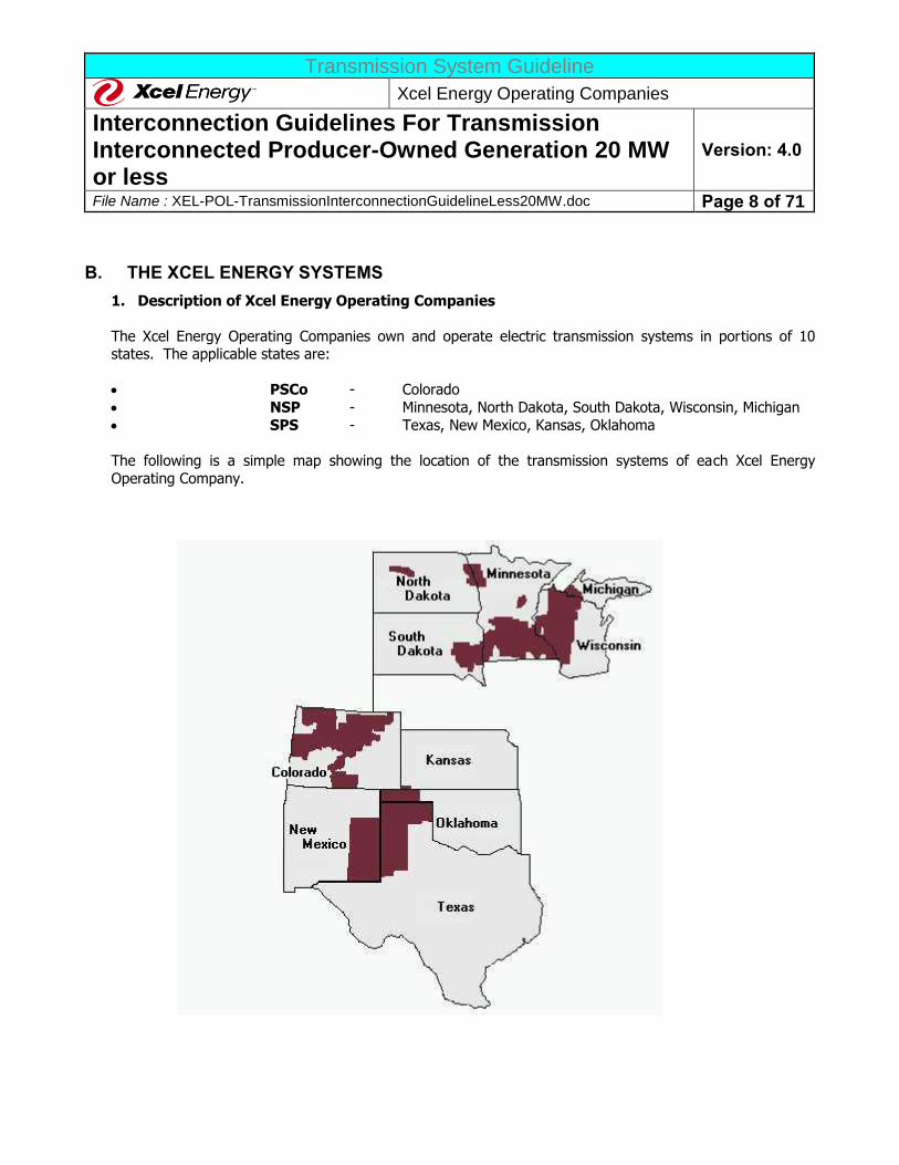
The Xcel Energy Operating Companies own and operate electric transmission systems in portions of 10 states. The applicable states are:
PSCo - Colorado
NSP - Minnesota, North Dakota, South Dakota, Wisconsin, Michigan
SPS - Texas, New Mexico, Kansas, Oklahoma
The following is a simple map showing the location of the transmission systems of each Xcel Energy
Operating Company.
Transmission System Guideline
Xcel Energy Operating Companies
Interconnection Guidelines For Transmission Interconnected Producer-Owned Generation 20 MW or less
Version: 4.0
File Name : XEL-POL-TransmissionInterconnectionGuidelineLess20MW.doc Page 9 of 71
Other electric utilities also serve these states, and in some areas the utilities operate highly interconnected
networks. A Producer must determine if the proposed generator will in fact interconnect to a transmission facility owned by an Xcel Energy operating company at the proposed location. If the generator will
interconnect to a transmission facility owned by another utility, these Guidelines are not applicable.
2. RELIABILITY REGIONS
The Xcel Energy Operating Company transmission systems are located in three NERC Reliability
Regions. Each Reliability Region has certain requirements that are specific to that region. The three regions are the Midwest Reliability Organization (MRO), the Southwest Power Pool (SPP), and the Western
Electricity Coordinating Council (WECC). The applicable Reliability Regions for each of the Xcel Energy Operating Companies are as follows:
PSCo - WECC www.wecc.biz
NSP - MRO www.midwestreliability.org SPS - SPP www.spp.org
3. Open Access Transmission Tariffs
The Xcel Energy transmission systems are also subject to three different OATTs on file with the FERC. The
NSP system is a member of the Midcontinent Independent System Operator, Inc. (MISO or Midcontinent ISO) regional transmission organization (RTO). The SPS system is a member of the SPP RTO. Each RTO
has an OATT on file with FERC.
The Applicable OATT, and the web site address, are as follows:
PSCo - the Xcel Energy Operating Companies Joint OATT, is available at the Xcel Energy web site
(www.xcelenergy.com); Xcel Energy > Transmission > Open Access Transmission Tariff
NSP - the Midcontinent Independent System Operator, Inc (MISO) regional OATT (MISO OATT) available at www.midwestiso.org (click on “Latest Tariff” icon)
SPS - SPP regional OATT (SPP OATT), available at http://sppoasis.spp.org/OASIS/SWPP (click on “Regional Tariff” in the matrix of selections)
Each OATT has been (or will be) amended to include the SGIP and SGIA required by the Final Rules, and
new generators will be subject to the processes in the OATTs. Specifically:
Generation interconnections to the PSCo transmission systems are subject to the procedures set
forth in the Xcel Energy Joint OATT and the technical requirements defined in these Guidelines.
Generation interconnections to the NSP transmission system are subject to the procedures set
forth in the MISO OATT and the technical requirements defined in these Guidelines.
Transmission System Guideline
Xcel Energy Operating Companies
Interconnection Guidelines For Transmission Interconnected Producer-Owned Generation 20 MW or less
Version: 4.0
File Name : XEL-POL-TransmissionInterconnectionGuidelineLess20MW.doc Page 10 of 71
Generation interconnections to the SPS transmission system are subject to the procedures in the
SPP OATT and the technical requirements defined in these Guidelines.
As indicated above, these Guidelines should be considered to be supplemental technical requirements to
the procedures and requirements set forth in the applicable OATT. To the extent there is a conflict
between these Guidelines and the applicable OATT, the applicable OATT will control unless FERC has accepted the Xcel Energy Guideline as consistent with the Final Rules.
C. GUIDELINE AUTHORITY
Several federal and state regulatory agencies have authority over the electric services provided by the Xcel
Energy operating companies. The requirements set forth by this document are intended to comply with these requirements, including the Federal Power Act (FPA), the Public Utility Regulatory Policies Act (PURPA), the
FERC Final Rules, all local, state and federal regulatory agency requirements, and the applicable requirements
of other entities related to owners and operators of electric systems and associated interconnected generation, such as NERC or the Regional Reliability Council. The Producer should keep abreast of changes in regulatory
requirements and comply with them as they develop. Specifically:
FERC has authority over any interconnection to an Xcel Energy electric transmission system at transmission
voltage under the FPA and the Final Rules. The Final Rules, and the individual OATTs implementing them
(listed above), are subject to change from time-to-time. The Producer should consult the applicable OATT to ensure that the most up to date OATT requirements are used in the project design, operation and maintenance
requirements.
NERC has established standards and practices for the reliable design and operation of the electric transmission
system. NERC and the individual Reliability Regions modify and update their requirements from time to time. The Producer should also consult the websites of NERC (www.nerc.com) and the applicable Reliability Region
(see above) to ensure that the most up-to-date requirements are used in the project design, operation and
maintenance requirements. This Guideline is periodically updated, but the Guideline may not reflect the most up-to-date information.
Various American National Standards Institute (ANSI) and Institute of Electrical and Electronic Engineers
(IEEE) standards also affect interconnection of generation and are mentioned in this Guideline. ANSI and IEEE
update and revise these standards from time to time. The Producer should plan its generation project using the latest revision of referenced ANSI/IEEE standards because Xcel Energy considers them to be automatically
incorporated into this Guideline.
The transmission systems in the individual Xcel Energy operating companies are or may become part of an Independent System Operator (ISO), a Regional Transmission Organization (RTO), or an Independent
Transmission Company (ITC) at some time in the future. For the purposes of this document, the term ISO,
unless specified otherwise, will be used to indicate all such possible regional transmission entities. As such changes occur, the requirements imposed on Xcel Energy by the applicable ISO will affect generation
interconnections. Xcel Energy plans to update these Guidelines from time-to-time to incorporate the changing
Transmission System Guideline
Xcel Energy Operating Companies
Interconnection Guidelines For Transmission Interconnected Producer-Owned Generation 20 MW or less
Version: 4.0
File Name : XEL-POL-TransmissionInterconnectionGuidelineLess20MW.doc Page 11 of 71
ISO requirements that become applicable, but the Producer should consult the ISO for any applicable ISO
requirements.
However, these Guidelines are not intended to modify any existing OATT or agreements that establish the rights
and obligations of Xcel Energy or the Producer. This document also is not intended to override or change any statutes, regulations or other applicable authority. In cases where national, Regional Council, or state or local
codes or regulations are in conflict with the provisions of these Guidelines, the national, state or local code will take precedence.
Since these Guidelines are subject to these various regulatory authorities, which are subject to change, Xcel
Energy reserves the right to revise these Guidelines from time-to-time without advanced notice.
D. GUIDELINE OBJECTIVES AND LIMITATIONS
These Guidelines serve as a reference for establishing Xcel Energy/Producer interconnection to operate Generation in parallel with an Xcel Energy electric transmission system (Xcel Energy System). The technical
terms used in this guide are defined in the GLOSSARY.
Generation is defined as any device producing (or releasing from storage) electrical energy. The guidelines
apply to both rotating machines and inverter systems.
Parallel Operation is defined as the operation of Interconnection Customer-owned generation with output
terminals connected directly to or through an intermediary’s system to Xcel Energy’s System. Parallel Operation may be long term, or momentary (“make before break”, “hot”, or “closed” transition).
Pursuant to the applicable OATT, Xcel Energy will permit any eligible Producer to operate generating equipment
in parallel with the Xcel Energy System. The OATT and these Guidelines state the minimum requirements for
independently owned generation to safely and effectively interconnect to Xcel Energy’s electric transmission system.
These Guidelines are formulated to provide the Producer with a reliable interconnection that minimizes
scheduling conflicts and other restrictions that could result in output restrictions while providing Xcel Energy
with the flexibility and authority necessary to preserve reliability. All of the elements necessary for Xcel Energy to achieve this flexibility will be under the control of Xcel Energy. All of the elements necessary for the Producer
to control, operate, and maintain its generation facility will be under the control of the Producer. The objective is a clear line or point of demarcation between the Xcel Energy and the Producer’s equipment, maintenance,
and operating responsibilities.
Any responsibilities and liabilities between Xcel Energy and the Producer will be detailed in the generation
interconnection agreement between Xcel Energy and the Producer. The terms “approve”, “approved”, and “approval” used throughout this document mean acceptance. “Approval” by Xcel Energy does not mean that
Xcel Energy endorses or is held responsible for the safety or reliability of a Producer’s design and facility.
Transmission System Guideline
Xcel Energy Operating Companies
Interconnection Guidelines For Transmission Interconnected Producer-Owned Generation 20 MW or less
Version: 4.0
File Name : XEL-POL-TransmissionInterconnectionGuidelineLess20MW.doc Page 12 of 71
E. INTERCONNECTION PROCESS
The following process applies to a Producer that proposes to (a) interconnect a generating unit to the Xcel Energy System or (b) increase the capacity of a generating unit interconnected with the System. These
procedures only apply to generation interconnections and establish the facility and facility cost estimates
associated with such interconnections.
If the proposed generation facility is to be interconnected to the NSP Transmission System:
This location is governed by MISO OATT and the interconnection process is administered by MISO. The specific written process is titled “Attachment R” to the MISO OATT, available on the MISO web page. If you would like
more information about the Midwest ISO, contact 317-249-5400 or email [email protected].
If the proposed generation facility is to be interconnected to the PSCo Transmission System:
These locations are governed by Xcel Energy’s OATT and the interconnection process is administered by Xcel
Energy’s Transmission Department. If you would like more information about the Xcel Energy OATT contact the
Transmission Account Representative at (303) 273-4693 or email [email protected]
If the proposed generation facility is to be interconnected to the SPS Transmission System:
This location is governed by the SPP OATT and the interconnection process is administered by the SPP. The specific written process is titled “Attachment V” of the SPP OATT, available on the SPP web page
(www.spp.org), under the “SPP Operations and Tariff Administration” homepage. If you would like more
Information you can also contact SPP at 501-664-0146.
Limitation: As determined by FERC, a request for interconnection of a generator does not constitute a request for transmission service. The process described in these Guidelines is not sufficient, nor intended, to
determine the capability of the transmission network to deliver the Producer’s power and energy to loads. A
Producer desiring transmission service from Xcel Energy or the appropriate ISO, including a System Impact Study if one is necessary, must follow the procedures of the Xcel Energy OATT or the appropriate ISO OATT in
requesting transmission service.
F. FINANCIAL OBLIGATION OF THE PRODUCER
The Producer will reimburse Xcel Energy fully for the costs to interconnect the generator to the extent allowed by the Final Rules and applicable OATT.
The following are examples (but not a complete list) of the Interconnection Costs that may be the responsibility
of the Producer: 1. Study analyses and related expenses to determine:
a. The feasibility to interconnect;
b. The transmission facilities required for interconnection;
Transmission System Guideline
Xcel Energy Operating Companies
Interconnection Guidelines For Transmission Interconnected Producer-Owned Generation 20 MW or less
Version: 4.0
File Name : XEL-POL-TransmissionInterconnectionGuidelineLess20MW.doc Page 13 of 71
c. The Xcel Energy System upgrades required for the interconnection;
d. Construction and project schedules; and e. Cost estimates and other related information.
2. Preparation of and presentation of study results to appropriate regional oversight committees or
planning groups. 3. Land and rights-of-way, including any required licensing or permitting.
4. The Producer’s Interconnection Facilities. 5. Meter installation, testing, and maintenance, including all parts and other related labor.
6. Meter reading and scheduling. 7. Telemetry installation, testing, and maintenance, including all parts and other related labor.
8. Operating expenses, including communication circuits.
9. Xcel Energy protective device installation, testing, equipment cost, and related labor. 10. Producer’s protective device and interlock review of design, inspection, and test witnessing.
11. Programming costs to incorporate generation data into Xcel Energy’s Energy Management System (EMS).
Any cost responsibilities detailed in the generation interconnection agreement between Xcel Energy and the
Producer that conflict with this section will take precedence over these Guidelines.
G. OWNERSHIP, OPERATION
Xcel Energy shall own and operate all transmission facilities constructed for the interconnection of an Producer’s
generation to the Xcel Energy System that are determined to be part of the transmission system Network Facilities, as defined in the Final Rules. Xcel Energy shall own all Xcel Energy Interconnection Facilities and
System Upgrades that Xcel Energy determines that it is appropriate to own. This includes, but is not limited to,
revenue meters, relaying, control systems, breakers, switches, bus work, and transmission lines. Xcel Energy may, at its option, contract with the Producer or a third party for construction of any or all of these facilities.
The Producer will normally construct and own, at a minimum all Interconnection Producer Interconnection
Facilities, unless the parties agree in the generation interconnection agreement that Xcel Energy will construct
these facilities.
If the Producer plans to contract with Xcel Energy to operate or maintain the Producer’s Interconnection Facilities, specific design considerations may be required that go beyond the minimum technical requirements
described in this document. To ensure the safety of Xcel Energy personnel and to minimize the opportunity for
human error, the Producer may be required to use certain Xcel Energy design standards or certain approved equipment manufacturers which may include but are not limited to: control panel layouts, ground grid designs,
personal ground attachments placed in approved locations, electrical clearances, and lighting of the electrical equipment for night operating. The Producer will pay for the training of Xcel Energy personnel, if required, to
operate and maintain this Producer-owned equipment. The Producer will be required to maintain their own stock of any necessary spare/emergency parts and make them available to Xcel Energy maintenance personnel
or contract employees.
Transmission System Guideline
Xcel Energy Operating Companies
Interconnection Guidelines For Transmission Interconnected Producer-Owned Generation 20 MW or less
Version: 4.0
File Name : XEL-POL-TransmissionInterconnectionGuidelineLess20MW.doc Page 14 of 71
All equipment, whether provided by Xcel Energy or the Producer, whose operation or failure can result in the
separation of an Xcel Energy System, must conform to the technical specifications of this Guideline.
H. OPERATION SUBJECT TO BALANCING AUTHORITY/TRANSMISSION OPERATIOR
Operation of all interconnected transmission equipment must be under the direction of a NERC-certified Balancing Authority/Transmission Operator (BA/TOP). PSCo is a NERC-certified BA/TOP for the
transmission and generation within its BA/TOP area. NSP is the TOP and the Local Balancing Authority (LBA) operator for the NSP system; MISO is the BA for the NSP system. SPS is the TOP in the SPS operating system;
SPP is the BA for the SPS system. SPS unregistered as a BA on March 11, 2014.
However, the Xcel Energy BA/TOP areas are not contiguous with the Xcel Energy Systems. In some cases, Xcel
Energy owns transmission facilities in the BA/TOP Area operated by another entity. Similarly, other utilities own transmission facilities within the Xcel Energy BA/TOP Areas. Xcel Energy will operate (switch) all equipment
that it owns or which is considered integral to the Xcel Energy System and is within an Xcel Energy BA/TOP Area. At its option, Xcel Energy may contract with another BA/TOP Area Operator to provide for any or all of its
operation requirements for transmission lines that Xcel Energy owns but are located outside of an Xcel Energy
BA/TOP Area.
I. GENERATOR CERTIFICATION AND ACCREDITATION
1. MRO RELIABILITY REGION GENERATION UNITS
All interconnected generator installations on the NSP system in the MRO Reliability Region must meet the MRO System Design Standards and be approved by MISO. In addition, Producers intending to supply Generation
Capacity to members of the MRO Generation Reserve Sharing Pool must demonstrate reliable generating
capacity capability. This is accomplished through the MRO Generation Accreditation process. Producers adding generation will be responsible for the cost of all study work performed by Xcel Energy required to obtain these
acceptances.
a. MRO Accreditation
If the Producer has secured an agreement to supply capacity to a MRO Member with an end use load
obligation from the Producer’s facility, the Producer will be subject to the MRO Accreditation process for inclusion of its facility’s resource into the MRO Generation Reserve Sharing Pool. The detailed
requirements and procedures for obtaining MRO Accreditation can be found in the MRO Generation
Reserve Sharing Handbook. Producers connecting to the NSP system may also ask their Xcel Energy Representative for information.
b. MRO Temporary Accreditation
Transmission System Guideline
Xcel Energy Operating Companies
Interconnection Guidelines For Transmission Interconnected Producer-Owned Generation 20 MW or less
Version: 4.0
File Name : XEL-POL-TransmissionInterconnectionGuidelineLess20MW.doc Page 15 of 71
A Producer may request MRO temporary Accreditation of its generation facility if the facility meets the
criteria set forth in the MRO Generation Reserve Sharing Handbook. After all the testing requirements have been met, all study work accepted by the appropriate entities, all required transmission facilities
constructed and commissioned and the generation facility has been proven reliable after commissioning,
final Accreditation can be requested. Xcel Energy can assist the Producer in obtaining the necessary acceptances at the Producer’s cost.
c. MRO Urge Testing Requirements
As part of the initial MRO Accreditation process, and for annual verification of accredited capacity, a
Producer must perform a MRO URGE (Uniform Rating of Generation Equipment) test. The test is usually
one to four hours in length dependent on Producer’s category of generation prime – mover (the initial test may be longer) and can be scheduled when the generator is in operation. The appropriate data
shall be recorded during the test for evaluation and submittal to MRO to obtain, maintain, and adjust as appropriate accredited capacity. The Producer is responsible for the cost of the URGE tests.
d. Fuel Availability Requirements for MRO Accreditation
Producers who accredit their generation facilities must demonstrate that their generator is capable of supplying their URGE rated capacity over the four (4) peak hours of a day for a five (5) day successive
period. The only exception to this rule applies if the Producer’s facility has been classified as a Variable Generation Resource, such as wind generation.
e. MRO Designated Variable Generation Resources
Producers with resources not meeting the requirements in the aforementioned paragraphs may still seek accreditation under the category of Variable Generation resources. The criteria for satisfying those
requirements are found in the MRO Generation Reserve Sharing Handbook.
f. Facility Extended Outage For Equipment Repair or Significant Facility Modification
Requirements
Producers with accredited resources that experience an outage (planned or unplanned) that has duration of 120 days or more must contact MRO directly or contact their MRO Member customers to
facilitate the extended accreditation process and maintain their accreditation status. Failure to do so
results in loss of accreditation, and the need to submit to the entire accreditation process once again.
g. MRO Region Emergency Requirement
The Producer agrees to make its accredited generation resources available for call by NSP, acting as a
Control Area Operator, for MRO Region Emergencies throughout the MRO season in which the resources are expected to operate. Unless Generator is unavailable due to planned maintenance or
mechanical failure (forced outage), the Producer shall be capable of bringing the Generator to full rated capabilities within 12 hours after receiving declaration by Xcel Energy of a MRO Region Emergency.
Transmission System Guideline
Xcel Energy Operating Companies
Interconnection Guidelines For Transmission Interconnected Producer-Owned Generation 20 MW or less
Version: 4.0
File Name : XEL-POL-TransmissionInterconnectionGuidelineLess20MW.doc Page 16 of 71
2. SPP RELIABILITY REGION GENERATION UNITS
There are no specific certification or accreditation requirements for new Generators in the SPP Reliability Region. However, SPP has requested FERC authorization to function as an RTO, and SPP may impose
additional obligations in the future. A Producer proposing to construct generation on the SPS system should keep up to date with applicable SPP requirements. SPP has a Generation Interconnection task force, which
will be developing requirements. New SPP requirements, if adopted, will apply.
3. WECC RELIABILITY REGION GENERATION UNITS
All transmission-connected generators are required to perform testing on initial startup consistent with the requirements of WECC to obtain certification. See Sections II.J.2 and V.H.2 for further discussion.
J. NERC AND REGIONAL ENTITY POLICIES AND STANDARDS COMPLIANCE As discussed in Section II.D., all generators operated normally in long term parallel with the Xcel Energy System
must satisfy NERC policies and standards and the applicable Reliability Region’s (MRO, SPP, or WECC) system
design standards for generation including providing data and other information. The interconnecting Producer and Xcel Energy must agree on how the Producer will accomplish these requirements. The Producer must agree
to assist Xcel Energy in determining the generator’s compliance with the NERC and the Reliability Region’s policies and standards and provide such information as required by NERC or the Reliability Region.
Generators 20 MW or less may be considered as Bulk Electric System (BES) depending on how they are interconnected to the system, inconsideration of other generators. The generator shall work with their
applicable Regional Entity to determine if they will be defined as BES.
All generators, if classified as Bulk Electric System (BES), must provide evidence that they have agreement with entities that identify the generator’s NERC defined Generator Owner, Generator Operator, Balancing Authority,
Transmission Operator, Transmission Planner, Resource Planner, Transmission Owner (if applicable) and
Planning Coordinator.
K. REGULATORY APPROVALS AND PERMITS
The schedule for interconnection and commercial operation of a new generation plant depends on obtaining
regulatory approvals and permits for construction of required facilities. Interconnection facilities and system
upgrades typically require several permits and regulatory approvals.
The Producer is responsible for obtaining all required permits and regulatory approvals for its interconnection facilities. Xcel Energy is responsible for obtaining approval for the permits and regulatory approvals necessary
for any Xcel Energy Interconnection Facilities or System Upgrades. The Producer's responsibility for the cost of Xcel Energy's permits and regulatory approvals will be determined by the applicable OATT.
Transmission System Guideline
Xcel Energy Operating Companies
Interconnection Guidelines For Transmission Interconnected Producer-Owned Generation 20 MW or less
Version: 4.0
File Name : XEL-POL-TransmissionInterconnectionGuidelineLess20MW.doc Page 17 of 71
In addition, regulatory approvals may be required to be obtained by neighboring systems if interconnection of
the Producer’s generator will make it necessary for system upgrades to be constructed on these systems.
The lead-time for obtaining these regulatory approvals and permits is often lengthy. This lead-
time should not be underestimated.
Transmission System Guideline
Xcel Energy Operating Companies
Interconnection Guidelines For Transmission Interconnected Producer-Owned Generation 20 MW or less
Version: 4.0
File Name : XEL-POL-TransmissionInterconnectionGuidelineLess20MW.doc Page 18 of 71
II. INTERCONNECTION TECHNICAL REQUIREMENTS
The requirements in this document apply to all generating equipment operated in long-term parallel operation with the Xcel Energy System. This applies to all rotating generators and inverter installations. If you have
question, please contact Xcel Energy. Contact information can be found at the Xcel Energy website
(www.xcelenergy.com). http://www.xcelenergy.com/Company/Transmission/Transmission_Organizations/Interconnections_for_Transmi
ssion.
A. GENERATION INTERCONNECTION SUBSTATION CONFIGURATION
An interconnecting generation Producer may interconnect at an existing Xcel Energy station or via a tap into an
existing Xcel Energy transmission line. The configuration requirements of the interconnection depend on where the physical interconnection is to occur and the performance of the system with the proposed interconnection.
Xcel Energy uses five standard substation configurations in various parts of its system: Single Bus, Ring Bus,
Main & Transfer Bus, Double-Bus, and Breaker-and-a-half Bus design. If the Producer interconnects to an
existing Xcel Energy substation, the interconnection must conform, at a minimum, to the original designed configuration of the substation. Generally, Xcel Energy will not allow a Ring Bus of greater than five breakers.
Adding a sixth breaker will require conversion of the station into a Breaker-and-half Bus design. Xcel Energy, at its sole discretion, may consider different configurations due to physical limitations at the site.
Typical interconnection configuration diagrams can be found in APPENDIX A. The figures represent generic
installations. Circumstances unique to each installation may cause the final configurations to differ significantly
from the examples shown. In any case, the Facilities Study will determine final configuration of the Interconnecting Facilities.
The Interconnection Facilities configuration will be allowed only if it does not jeopardize the transmission
system’s ability to operate reliably and safely during generation unit trips (except during a local breaker failure
backup operation) and generator maintenance activities. Any circuit breaker that can directly impact the reliability and the security of the Xcel Energy System will be under the sole ownership and control of Xcel
Energy. In some cases, this will require the installation of an additional breaker in the facility of the Producer in order for the Producer to exercise maintenance control, ongoing operational control, and personnel safety.
If the Producer interconnects into an existing Xcel Energy substation or transmission line, Xcel Energy requires
the Customer to have a breaker on the high voltage side of their generator step-up transformer.
B. MODELING INFORMATION All generator/exciter/governor manufacturers’ data sheets must be available for modeling in transient/voltage
stability, short circuit, and relay setting calculation programs. This includes generator reactive capability curves and exciter saturation curves. The Producer shall provide to the Transmission Provider, at the time of
application for interconnection, the model data for the proposed generation and any associated power
Transmission System Guideline
Xcel Energy Operating Companies
Interconnection Guidelines For Transmission Interconnected Producer-Owned Generation 20 MW or less
Version: 4.0
File Name : XEL-POL-TransmissionInterconnectionGuidelineLess20MW.doc Page 19 of 71
conversion equipment and controls if an appropriate IEEE standard model exists. If an IEEE model does not
exist, the Producer shall provide suitable user model(s) and associated documentation for use with dynamic and transient stability simulations of their equipment. The modeling data must be provided in both General Electric’s
PSLF format or Power Technologies Inc.’s PSSE format for connections to PSCo system and in PSSE format for
connections to SPS or NSP systems, or as instructed by the entity doing the studies. The Producer shall provide, upon request, the model data for the proposed generation and any associated power conversion equipment and
protective devices for use with an Electromagnetic Transients Program (EMTP), Alternate Transients Program (ATP), or PSCAD program.
The Producer will annually forecast the firm MW and Mvar usage on each plant Reserve Station auxiliary system
for when the generator is on-line, off-line, and starting/stopping, and provide this information annually to Xcel
Energy. Power for use when the Producer is off-line, if needed, must be provided for in accordance with FERC, NERC, NERC Regions, Electric Reliability Organization (ERO), Reliability Entities (RE), ISO and/or local state
requirements. In some instances, this power may need to be arranged for with the local electric distribution provider.
C. SEPARATE SYSTEMS A separate system is defined as one in which there is no possibility of connecting a Producer's generating
equipment in parallel with Xcel Energy’s System. This can be accomplished by either an electrically or a mechanically interlocked switching arrangement which prevents the two power sources (Xcel Energy and
Producer) from serving a power load simultaneously. If a Producer has a separate system, Xcel Energy will require verification that the system meets the non-parallel requirements. This will be accomplished by the
approval of drawings by Xcel Energy in writing and, if Xcel Energy so elects, by field inspection of the transfer
scheme. Xcel Energy requires that the final design prints be sealed by a Professional Engineer (P.E.) with a brief description of the non-paralleling scheme documented on the prints. Generating systems that connects
directly to Xcel Energy’s System may require backup relaying (besides the generator protection relaying) to protect Xcel Energy’s System from adverse impacts from accidental paralleling. Xcel Energy will make these
determinations on a case-by-case basis.
D. PARALLEL OPERATION
A parallel system or parallel generation is defined as one in which the generation of a Producer can be connected to Xcel Energy’s System. A transfer of power between the two systems is a direct and often desired
result. The parallel can be by direct connection to Xcel Energy’s System or via the internal electrical system of
an entity to which the Producer is connected such as in an industrial plant. Regardless of the connection means, Xcel Energy’s parallel operation requirements still apply to that Producer.
E. PROTECTIVE DEVICES
The Producer is responsible for the overall safe and effective operation of their generating facility. Certain protective devices (relays, circuit breakers, etc.) that are specified by Xcel Energy must be installed at the
location where a Producer desires to operate generation in parallel with the Xcel Energy System. The purpose
of these devices is to promptly disconnect a Producer's generating equipment from Xcel Energy’s System
Transmission System Guideline
Xcel Energy Operating Companies
Interconnection Guidelines For Transmission Interconnected Producer-Owned Generation 20 MW or less
Version: 4.0
File Name : XEL-POL-TransmissionInterconnectionGuidelineLess20MW.doc Page 20 of 71
whenever faults or abnormal operating conditions occur. Other modifications to the electrical system
configuration or protective relays may be required in order to accommodate parallel generation.
Xcel Energy will not be responsible for primary protection of equipment in the Producer’s substation or
Generating Facility. Protective devices (e.g. relays, circuit breakers) must be installed by the Producer to the
full extent required by all applicable standards to disconnect the Producer's generation from the Xcel Energy System whenever a fault or abnormality occurs (including local breaker-failure tripping whenever the normal
relaying does not work). Such equipment must coordinate with existing Xcel Energy equipment and provide comparable levels of protection as practiced on Xcel Energy’s System. The protective devices differ with the
size of the installation. The specific requirements will be determined in the Interconnection and Facilities Studies. Major factors generally determining the type of protective devices required include:
1. The type and size of the Producer's generating equipment.
2. The location and system voltage level of the Producer’s connection to Xcel Energy’s System.
3. The manner in which the installation will operate (one-way versus two-way power flow).
However, this Guideline does not address all of the nuances and complexities involved in designing a protection
scheme or for integrating a generation unit into an interconnected electric transmission system. The Producer is responsible for designing their own protection scheme and should consult an expert in the field of system
protection, generation controls, etc.
Specific protective device requirements are described in Section III below.
F. INTERFERENCE
Operation of the generator by the Producer must not cause unusual fluctuation or disturbance on, or inductive interference with an Xcel Energy System, other generators or loads connected to the Xcel Energy System. If
such fluctuations or disturbance occur, the Producer will be disconnected and required to install suitable apparatus to reasonably correct or limit such fluctuation, disturbance, or interference at no expense to Xcel
Energy or Xcel Energy’s other producer or customers.
G. VOLTAGE, HARMONICS, AND FLICKER The interconnection of a Producer's generating equipment with Xcel Energy’s System shall not cause any
reduction in the quality of service on the Xcel Energy System. No abnormal voltages, frequencies, or interruptions will be permitted. If high- or low-voltage complaints, transient voltage complaints, and/or
harmonic (voltage distortion) complaints result from operation of a Producer's generation, Producer’s such generating equipment shall be disconnected from Xcel Energy’s System until the Producer resolves the problem.
The Producer is responsible for the expense of keeping the generator(s) in good working order so that the
voltage, harmonics, power factor (PF), and var requirements are always met. Variable output machines (wind), with fluctuations in plant MW output, may cause fluctuation in power system voltage. To achieve adequate
speed of response to such variations, and plants relying on switched shunt capacitors to control such variations must have the capacitor banks equipped with “rapid discharge” circuits capable of rendering the capacitors
available for re-insertion within 5 seconds of de-energization.
Transmission System Guideline
Xcel Energy Operating Companies
Interconnection Guidelines For Transmission Interconnected Producer-Owned Generation 20 MW or less
Version: 4.0
File Name : XEL-POL-TransmissionInterconnectionGuidelineLess20MW.doc Page 21 of 71
Control systems for any energy conversion equipment(s) employed shall be designed to preclude excitation of
the sub-synchronous modes of oscillation of existing turbine-generators, during either steady-state or dynamic conditions, including converter restart attempts or repeated commutation failures. Similarly, excitation of
existing or new power system resonances (whether sub- or super-synchronous) due to non-fundamental current
injection shall be effectively prevented.
1. STEADY STATE VOLTAGE RANGE
The Producer should expect a normal transmission operating voltage range of +/- 5% from nominal. The
Producer should contact Xcel Energy to determine the normal operating voltage at their point of interconnection. The plant should be capable of start-up whenever the voltage at the point of
interconnection is within this range. If the auxiliary equipment within the Generator cannot operate within
the above range, the Generator will need to provide regulation equipment to limit the station service voltage-level excursions. During system contingency or emergency operation, operating voltages may vary
up to +/- 10% from nominal.
2. DYNAMIC VOLTAGE RANGE
a. MRO REGION
The NSP transmission system is designed to avoid dynamic voltage dips below 0.7 p.u. voltage due to
external faults or other disturbance initiators to meet MRO requirements. Dynamic voltage excursions within this range can be expected. Dropout of control contactors associated with any essential
generator auxiliaries should not occur during dynamic-power system voltage-swings to levels as low as 0.7 p.u. If contactor dropout does occur, and this causes a further voltage excursion, the Producer is
required to resolve this problem in a timely manner.
Power conversion or conditioning equipment, either for conversion of output or other reasons such as
excitation supply to the rotor circuits of wound-rotor induction machines and protective devices, should also be capable of satisfactory performance (no trip-out, commutation failures or blocking) during
voltage swings. Successful commutation and continued power generation should be possible during
dynamic voltage swings to levels as low as 0.7 p.u. The low-voltage-withstand capability of this equipment should be able to tolerate a duration of 0.7 p.u. voltage of 0.5 seconds and a total time
during which the voltage is below 0.9 p.u. of 2.0 seconds per occurrence. Due to power system dynamic-response characteristics, such dynamic under-voltage occurrences may be experienced
repetitively in a back-to-back manner. High-voltage swings of up 1.2 p.u. voltage are also possible.
The Voltage Control Response Rate (for synchronous generators, the exciter response ratio) is the
speed with which the voltage-controlling device reacts to changes in the system voltage. The minimum response rate for a static excitation system shall have the exciter attain 95% of the exciter’s ceiling
(maximum) voltage in 0.1 seconds. The exciter ceiling voltage shall be at least two times the exciter voltage at the rated full load value. For rotary exciters, the exciter response ratio shall be at least 2.0.
The response ratio, ceiling voltage, and speed of response are defined in IEEE 421A. Non-synchronous
generators should be designed to meet a similar Voltage Response Rate. However, excitation system
Transmission System Guideline
Xcel Energy Operating Companies
Interconnection Guidelines For Transmission Interconnected Producer-Owned Generation 20 MW or less
Version: 4.0
File Name : XEL-POL-TransmissionInterconnectionGuidelineLess20MW.doc Page 22 of 71
capabilities less than the ones stated above may be considered for a wind generation where those
capabilities will not negatively impact the NSP System.
In no case can failure of a generator to be able to withstand these dynamic voltage excursions result in
the excursion exceeding 0.7 p.u. during the event.
b. WECC Region
WECC requires that for a single contingency, transient voltage dips cannot exceed 25% at load buses, or 30% at non-load buses, and frequency cannot dip below 59.6 Hz for 6 cycles or more at a load bus.
For multiple contingencies, transient voltage dips cannot exceed 30% at any bus and cannot exceed
20% for more than 40 cycles at any load bus, and frequency cannot dip below 59.0 Hz for 6 cycles or more at a load bus. The addition of any new generation cannot produce system performance that is out
of compliance with the values stated above.
c. SPP Region
SPP does not have any dynamic voltage performance criteria. The requirements for each generator will
be assessed on a case-by-case and location specific evaluation by SPP under Part V to the SPP OATT. SPP is currently reviewing the addition of dynamic voltage performance criteria. New rules if adopted,
will apply.
3. FLICKER AND OTHER VOLTAGE VARIATIONS
Generators are not allowed to produce flicker that impacts adjacent producers and customers and that exceeds IEEE 519 and IEEE 1453. The Producer will be responsible for corrections if their facility is the
cause of objectionable flicker levels. For induction generators, where starting will have an adverse impact on Xcel Energy’s System voltage, step-switched capacitors, or other techniques may be required
to limit the voltage changes.
4. HARMONICS
The equipment of the Producer must include protective equipment so the Producer does not introduce
excessive distortion to Xcel Energy’s System voltage and current waveforms as defined by IEEE 519. Total harmonic distortion (THD) from the facility will be measured at the FERC defined term Point of
Interconnection (POI). The point of common connection (PCC), as used in IEEE 519, is considered synonymous with POI for this Guideline. The harmonic distortion measurements are made at the point
of interconnection between the Producer and the Xcel Energy System. The measured results must be
within the limits specified in IEEE 519. The Producer is encouraged to ensure that the facility as designed will comply with these requirements early in the design process. The Producer is responsible
for the elimination of any objectionable interference (whether conducted, induced, or radiated) to communication or signaling circuits or systems, or any miss-operation, failure, or overloading of power
system devices or equipment (protective relays, capacitor banks, metering, etc.) arising from non-
fundamental current injections into the Xcel Energy System from the Producer’s facilities.

Transmission System Guideline
Xcel Energy Operating Companies
Interconnection Guidelines For Transmission Interconnected Producer-Owned Generation 20 MW or less
Version: 4.0
File Name : XEL-POL-TransmissionInterconnectionGuidelineLess20MW.doc Page 23 of 71
Output energy present at any frequency (harmonic or non-harmonic) in the range 220-420 Hz is limited to 1.0% of the fundamental current. This additional requirement is for ensuring that no harmful
interference occurs to existing 260 Hz and 380 Hz ripple-based load control systems in use by adjacent
interconnected power suppliers. Note that the fifth through seventh harmonics of 60 Hz fall within the ripple-system protection range. Any power conversion equipment employing six-pulse configurations
may require special power-quality measures to satisfy this requirement. Any reference to “load current” in IEEE 519 should be interpreted as referring to output current of the interconnecting facility, as
measured at the point of interconnection.
Since inverters can be a significant harmonic source, IEEE 519 shall be followed explicitly. Producers
that utilize inverters with their generators shall adhere to the guidelines for inverters.
H. FREQUENCY AND FREQUENCY CONTROL
The energy delivered to Xcel Energy’s System must be 60 Hz sinusoidal alternating current at a standard voltage and phase rotation. Xcel Energy’s phase rotation is ABC counter-clockwise in most areas. The
Producer should verify rotation with Xcel Energy before purchasing any equipment.
1. GOVERNOR OPERATION
All generating equipment must be designed to continuously operate between 59.5 and 60.5 hertz. The
Producer will operate its generator consistent with Xcel Energy’s guidelines and requirements concerning frequency control. Governors must be maintained and tested in accordance with the
manufacturers’ specifications to maintain the performance stated in this section. The Producer must, at its sole expense, be responsible for this maintenance and testing of the generating equipment.
a. Generators shall be equipped with governors that sense frequency (unless exempt under
MRO/SPP/WECC and NERC rules due to prime mover or regulatory limitations).
b. Governors shall provide a zero to ten percent (0-10%) adjustable setting nominally set at a three percent (3%) droop characteristic (MRO) and 5% (SPP and WECC) and a ±0.36 hertz or
less dead band unless agreed otherwise by Xcel Energy. c. The generator must begin increasing or decreasing output at frequency set points of 59.64
hertz or 60.36 hertz respectively.
d. The change in output must begin occurring within 0.5 seconds of a detected frequency disturbance.
2. MRO REGION OVER/UNDER-FREQUENCY GENERATION TRIPPING
All transmission connected generators, if installed with over/under frequency tripping relays, must be
set to coordinate with the under frequency load shedding program in MRO region. MRO region’s under frequency load shedding (UFLS) program is presently being modified based on IEEE standard, C37.106-
2003 and will be similar to WECC UFLS guidelines.
Transmission System Guideline
Xcel Energy Operating Companies
Interconnection Guidelines For Transmission Interconnected Producer-Owned Generation 20 MW or less
Version: 4.0
File Name : XEL-POL-TransmissionInterconnectionGuidelineLess20MW.doc Page 24 of 71
All generators in MRO region will be required to follow WECC guidelines as specified in the following clause until MRO regional guidelines are established. The Producer is required to report their generator
off-nominal frequency tripping relay settings to Xcel Energy.
3. SPP REGION OVER/UNDER-FREQUENCY GENERATOR TRIPPING
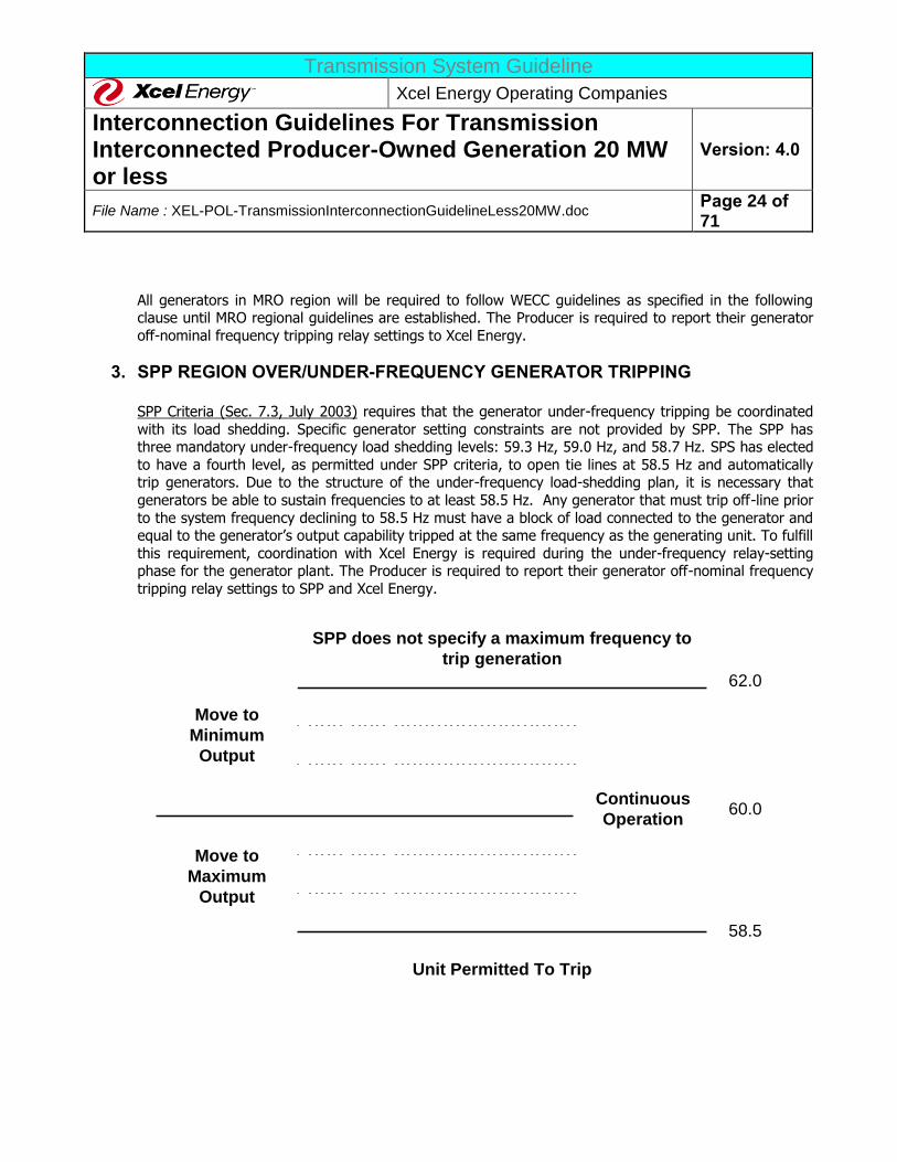
SPP Criteria (Sec. 7.3, July 2003) requires that the generator under-frequency tripping be coordinated
with its load shedding. Specific generator setting constraints are not provided by SPP. The SPP has three mandatory under-frequency load shedding levels: 59.3 Hz, 59.0 Hz, and 58.7 Hz. SPS has elected
to have a fourth level, as permitted under SPP criteria, to open tie lines at 58.5 Hz and automatically trip generators. Due to the structure of the under-frequency load-shedding plan, it is necessary that
generators be able to sustain frequencies to at least 58.5 Hz. Any generator that must trip off-line prior
to the system frequency declining to 58.5 Hz must have a block of load connected to the generator and equal to the generator’s output capability tripped at the same frequency as the generating unit. To fulfill
this requirement, coordination with Xcel Energy is required during the under-frequency relay-setting phase for the generator plant. The Producer is required to report their generator off-nominal frequency
tripping relay settings to SPP and Xcel Energy.
Continuous
Operation
62.0
SPP does not specify a maximum frequency to
trip generation
58.5
Unit Permitted To Trip
Move to
Minimum
Output
Move to
Maximum
Output
60.0
Transmission System Guideline
Xcel Energy Operating Companies
Interconnection Guidelines For Transmission Interconnected Producer-Owned Generation 20 MW or less
Version: 4.0
File Name : XEL-POL-TransmissionInterconnectionGuidelineLess20MW.doc Page 25 of 71
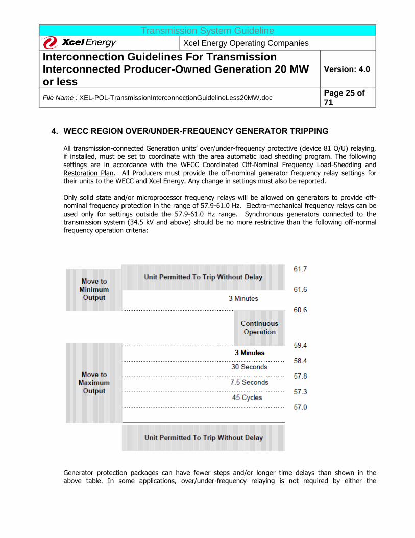
4. WECC REGION OVER/UNDER-FREQUENCY GENERATOR TRIPPING
All transmission-connected Generation units’ over/under-frequency protective (device 81 O/U) relaying, if installed, must be set to coordinate with the area automatic load shedding program. The following
settings are in accordance with the WECC Coordinated Off-Nominal Frequency Load-Shedding and
Restoration Plan. All Producers must provide the off-nominal generator frequency relay settings for their units to the WECC and Xcel Energy. Any change in settings must also be reported.
Only solid state and/or microprocessor frequency relays will be allowed on generators to provide off-
nominal frequency protection in the range of 57.9-61.0 Hz. Electro-mechanical frequency relays can be used only for settings outside the 57.9-61.0 Hz range. Synchronous generators connected to the
transmission system (34.5 kV and above) should be no more restrictive than the following off-normal
frequency operation criteria:
Generator protection packages can have fewer steps and/or longer time delays than shown in the
above table. In some applications, over/under-frequency relaying is not required by either the
Transmission System Guideline
Xcel Energy Operating Companies
Interconnection Guidelines For Transmission Interconnected Producer-Owned Generation 20 MW or less
Version: 4.0
File Name : XEL-POL-TransmissionInterconnectionGuidelineLess20MW.doc Page 26 of 71
equipment manufacturer or by Xcel Energy. Any generator that does not have frequency relaying
automatically complies with the above table.
The Producer is responsible for protecting their generation units. The manufacturer’s recommendations
for some units may be more restrictive than the values shown in the table. In such cases, the Producer should follow the manufacturer’s recommendations. Producers who have units that violate the table
values above must contract with Xcel Energy or another entity to trip an equivalent amount of additional load for off-frequency excursions in accordance with the WECC Coordinated Off-Nominal
Frequency Load-Shedding and Restoration Plan.
I. GENERATOR REACTIVE CAPABILITY
1. INDUCTION GENERATORS AND INVERTERS
Induction generator installations must provide power factor control within a range of 0.95 leading to
0.95 lagging at the system operating voltage at the PoCo. The Producer must provide any capacitors or
other devices needed to achieve this power factor performance level. Under lagging reactive power facility conditions, the Producer is responsible for ensuring that self-excitation of the induction
generators does not occur, including under the various outage combinations that might occur in the local Xcel Energy System. The Producer is responsible for ensuring that high-voltages from self-
excitation are not applied to the Xcel Energy System.
Reactive power supply requirements for inverter systems can be similar to those for induction
generators. Self-commutated inverters must meet the same requirements as synchronous generators, and line commutated inverters must meet the same requirements as induction generators.
2. MINIMUM POWER FACTOR REQUIREMENTS
Generators generally must provide for their own reactive power needs, including the reactive power
needs of their Generator Step-Up transformer (GSU). Producers that provide service to themselves at
retail will be expected to provide sufficient facilities and controls to operate their combined generation and load within a range of 0.95 leading to 0.95 lagging power factor of the load or be subject to the
power factor penalties associated with the service rate. All other generators are required to provide reactive power, upon the request of the system dispatchers, within a range of 0.95 leading to 0.95
lagging at the system operating voltage, as measured at the POI (unless a greater range is specified
under an ancillary services contract). The Generator must respond dynamically to meet system performance requirements unless exempted. The Generator is expected to provide reactive power up to
the generation unit’s reactive power capability curve (a.k.a. “D” Curve, see typical diagram below) during system emergency conditions.
Some portions of the Xcel Energy System (the NSP system in North Dakota) are located in or adjacent
to control areas where other load serving entities (municipals or cooperatives) utilize "ripple" load
management systems. These systems employ an on-off keyed carrier signal (typically in the range of
Transmission System Guideline
Xcel Energy Operating Companies
Interconnection Guidelines For Transmission Interconnected Producer-Owned Generation 20 MW or less
Version: 4.0
File Name : XEL-POL-TransmissionInterconnectionGuidelineLess20MW.doc Page 27 of 71
150-400 Hz) injected into the power systems to address customer-site load-management devices. The
installation of shunt capacitor banks, as may be required for power factor correction of induction machines, or for providing capacitive output capability, may cause degradation of the ripple signal
strength by shunting to ground the ripple signal through the capacitor bank(s). To prevent such
degradation, appropriate tuned blocking filters may be required.
3. VOLTAGE CONTROL BY GENERATION RESOURCES
Voltage Control is a FERC defined ancillary service under the applicable OATT. These are Xcel Energy’s
present minimum requirements for such service. However, the final requirements will be based on any mandated MISO/SPP/WECC, NERC, or ISO interconnection requirements. Any generator providing this
service to the Control Area Operator must be able to automatically control the voltage level by adjusting the machine’s power factor within a continuous range of between + 0.90 to - 0.90 power factor based
on the station’s sum total name plate generating capability as measured at the transmission system’s
point of interconnection. The voltage or var set point that the generator needs to maintain will be established and dispatched as necessary by Xcel Energy’s Control Centers.
4. GENERATOR TRANSFORMER SPECIFICATIONS
The generator transformer specifications (including taps if applicable) will be jointly determined by Xcel Energy and the Producer to insure proper coordination of voltages and regulator action. The ANSI
Standards require that generators be capable of delivering rated power capability when operated within
+/-5% of its rated terminal voltage. The generators of the Producer shall operate to fulfill this requirement by selecting the appropriate generator main-power transformer tap ratio setting. In some
cases, such as facilities with a high-impedance Generator Step-Up Transformer (GSU), voltage regulators (or tap changing under load) will need to be installed at the expense of the Producer.
Furthermore, the final GSU transformer winding tap ratio is often selected so as to supply a voltage boost over the nominal generator terminal operating voltage (e.g., 13.2kV GSU LV tap for 13.8kV gen.
terminal nominal voltage). This provides compensation for VAR absorbed by the GSU transformer,
needed to be accounted for in the HV side POI power factor requirements.
5. GENERATOR CAPABILITY CURVES
A copy of the generator capability curves supplied by the generator manufacturer must be provided to Xcel Energy for each generator at the Producer’s facility as soon as the information is available. These
curves, along with related electrical impedance data on the generator and step-up transformers, must
be supplied prior to the final On-Line Testing, including the var capability testing, required before a facility can be declared commercial.
Either stator or rotor winding heating limits the allowable reactive power. The generator reactive
capability is greatly affected by cooling. The figure below illustrates the impact of different hydrogen pressures. Many generators are air-cooled and ambient air temperatures have a major impact on
generator output ability. The Producer is required to operate the cooling at full rated hydrogen
pressures and to ensure full machine capability is maintained under normal conditions.
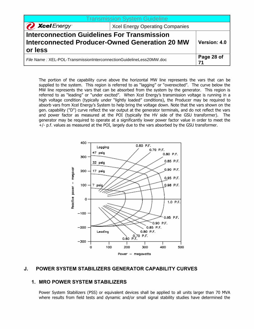
Transmission System Guideline
Xcel Energy Operating Companies
Interconnection Guidelines For Transmission Interconnected Producer-Owned Generation 20 MW or less
Version: 4.0
File Name : XEL-POL-TransmissionInterconnectionGuidelineLess20MW.doc Page 28 of 71
The portion of the capability curve above the horizontal MW line represents the vars that can be
supplied to the system. This region is referred to as “lagging” or “overexcited”. The curve below the MW line represents the vars that can be absorbed from the system by the generator. This region is
referred to as “leading” or “under excited”. When Xcel Energy’s transmission voltage is running in a
high voltage condition (typically under “lightly loaded” conditions), the Producer may be required to absorb vars from Xcel Energy’s System to help bring the voltage down. Note that the vars shown on the
gen. capability ("D") curve reflect the var output at the generator terminals, and do not reflect the vars and power factor as measured at the POI (typically the HV side of the GSU transformer). The
generator may be required to operate at a significantly lower power factor value in order to meet the +/- p.f. values as measured at the POI, largely due to the vars absorbed by the GSU transformer.
J. POWER SYSTEM STABILIZERS GENERATOR CAPABILITY CURVES
1. MRO POWER SYSTEM STABILIZERS
Power System Stabilizers (PSS) or equivalent devices shall be applied to all units larger than 70 MVA
where results from field tests and dynamic and/or small signal stability studies have determined the
Transmission System Guideline
Xcel Energy Operating Companies
Interconnection Guidelines For Transmission Interconnected Producer-Owned Generation 20 MW or less
Version: 4.0
File Name : XEL-POL-TransmissionInterconnectionGuidelineLess20MW.doc Page 29 of 71
potential for unit or system instability and where the condition can be improved or corrected by the
application of such devices.
The MRO-S2 Criteria requires power system stabilizers or equivalent devices shall be designed and
tuned to have a positive damping effect on local generator oscillations as well as inter-plant and inter-area oscillations without deteriorating turbine/generator shaft torsional oscillation damping. The power
system stabilizer shall be designed to ensure system performance as defined in Categories A, B, and C of Table I.A. Standards on Transmission Systems, and the MRO Disturbance-Performance Table.
The Producer and the Transmission Provider must work jointly and provide results, prior to the
generator’s in-service date and as required by changes in system conditions, which clearly show
whether or not power system stabilizers or equivalent devices are required on the generator(s) in question. The Producer must provide results from field tests, such as Automatic Voltage Regulator
(AVR) open circuit 2% and 5% step response tests). The Transmission Provider shall provide dynamic stability and/or small signal stability study results. These results should provide evidence of high
generator relative participation (relative participation factors greater than 0.1 or 10%) in a range of
local, inter-plant and inter-area modes (0.1 to 2.0 Hz).
Producers and the Transmission Provider must work jointly and provide results, prior to the Generator’s in-service date and as required by changes in system conditions, that demonstrate compliance with the
system performance requirements as defined in Categories A, B, and C in Table I of Standard I.A. and the MRO Disturbance-Performance Table. The Producer must provide results from field tests such as a
frequency response test to verify the power system stabilizer linear characteristics. (Detailed
information about generator test data can be found in the MRO Generator Testing Requirements.) The Transmission Provider shall provide dynamic stability and/or small signal stability study results. Any
non-compliance shall be documented, including a plan for achieving compliance.
Documentation of these assessments shall be provided to the Regional Reliability Council and those
entities responsible for the reliability of the interconnected transmission systems upon request.
Transmission System Guideline
Xcel Energy Operating Companies
Interconnection Guidelines For Transmission Interconnected Producer-Owned Generation 20 MW or less
Version: 4.0
File Name : XEL-POL-TransmissionInterconnectionGuidelineLess20MW.doc Page 30 of 71
2. WECC POWER SYSTEM STABILIZERS
a. The following criteria shall be used to determine when a PSS must be installed on a synchronous generator, regardless of ownership, that is connected to the transmission system (by generator
step-up transformer to 60 kV or higher voltage):
WECC currently does not require PSS for generators less than 30 MW.
b. When a Generator that is equipped with a functional PSS is on line, the PSS shall be in operation except for the following reasons:
i. Maintenance and testing. ii. PSS exhibits instability due to nonstandard transmission line configuration.
iii. PSS does not operate properly due to a failed component.
iv. Unit is operating in the synchronous condenser mode (very near zero power level). v. When a unit is generating less power than its design limit for effective PSS operation.
vi. When a unit is passing through a range of output that is a known “rough zone”.
The aggregate MVA of the synchronous machines that are on line and equipped with a
functioning PSS shall not fall below the level identified in the most recent power system stabilizer study commissioned by the WECC.
c. When a synchronous generator that is equipped with a PSS is operating in the pump mode (P/G
unit), and is connected to a transmission system such that the PSS does not produce negative
damping, the PSS should be in service.
d. PSS equipment must be tested and calibrated in conjunction with AVR testing and calibration.
This will be done as often as is necessary to maintain reliable PSS performance in accordance with the “WECC PSS Tuning Criteria” (available on WECC website, www.wecc.biz). PSS
recalibration must be performed if AVR response parameters are modified. When a PSS is taken out of service because of a failed component, the party responsible will be expected to perform
the needed repairs (or replacement) in a responsible and timely manner.
e. A PSS is not required for a synchronous condenser.
It is the responsibility of the Producer to arrange for any and all design modeling, settings, testing, and field adjustments necessary to incorporate the PSS as an operational part of the
generator’s control system. Xcel Energy must be given the opportunity to review the PSS setting data and test procedures, and to witness the testing and operation of the Generator’s PSS.
Whenever the generator is connected to the Xcel Energy System, the Generator’s PSS must be
operated in-service. An exception is allowed for testing. The PSS should be tested periodically.
The WECC has established settings, modeling, and testing guidelines for PSS systems, per the WECC Planning Coordination Committee document of March 21, 1997 on “Testing of Synchronous
Transmission System Guideline
Xcel Energy Operating Companies
Interconnection Guidelines For Transmission Interconnected Producer-Owned Generation 20 MW or less
Version: 4.0
File Name : XEL-POL-TransmissionInterconnectionGuidelineLess20MW.doc Page 31 of 71
Unit Reactive Limits and Dynamic Testing/Model Validation”. The Producer must provide
complete documentation of PSS related settings and test data to Xcel Energy prior to the Producer’s facility being declared ready for “Commercial Operation.” This documentation must be
in compliance with the WECC test/data forms included with the aforementioned WECC 1997
document.
In addition to the PSS, the generator’s AVR shall be an integral part of the excitation control system. All generators 10 MVA and larger must be equipped with automatic voltage control
equipment. All generating units with automatic voltage control equipment must normally be operated in a voltage control mode. These generating units must not be operating in any other
mode (e.g. constant power factor control) unless authorized to do so by the Control Area
Operator. The AVR must be properly tuned and tested in accordance with IEEE 421 for continuously acting AVRs. All AVRs must be in-service at all times that the Producer’s generator is
connected to Xcel Energy. The generator’s AVR must be able to ride through reactive element switching on the Xcel Energy System. An exception is allowed for testing.
3. SPP POWER SYSTEM STABILIZERS
SPP does not require power system stabilizers at this time, however, the inclusion of a PSS is preferred. SPP is currently reviewing the policy for PSS. New rules for PSS, if adopted, will apply.
K. Fault Current
Xcel Energy’s protective equipment fault current capability is based on the use of equipment with greater
capability than the maximum fault current available at a location. The Producer’s equipment capability must exceed the maximum fault current available. On the Xcel Energy System, this value may be over 63,000
amps. The exact value of available fault current depends upon location and circuit configuration and will be
determined in the Interconnection Facilities studies. The Producer must work closely with Xcel Energy at the time of the interconnection design to determine the available fault current at the specific location of
interconnection. In addition this value may increase over time due to growth and changes in the interconnected power system. Therefore, the Producer should make accommodations for reasonable
increases in fault current in designing its Facility.
L. SYSTEM RESTORATION AND BLACK START CAPABILITY
Under an extreme emergency, large portions of the U. S. electric power grid may shut down. The Xcel
Energy Control Areas, in conjunction with MRO, SPP, and WECC, have developed a process for restoring the Xcel Energy Control Areas and, by request, adjacent Control Areas. Xcel Energy may need to obtain more
black start capability from time to time. If the Producer is interested in pursuing this service, indicate so on your application to get the specific details and requirements.
Transmission System Guideline
Xcel Energy Operating Companies
Interconnection Guidelines For Transmission Interconnected Producer-Owned Generation 20 MW or less
Version: 4.0
File Name : XEL-POL-TransmissionInterconnectionGuidelineLess20MW.doc Page 32 of 71
M. DISCONNECT DEVICE/POINT OF DEMARCATION
A disconnect device must be installed to isolate Xcel Energy’s System from the Producer’s generation. This disconnect shall be installed and owned by the Producer and shall provide a visible air gap and lock to
establish required clearances for maintenance and repair work of the Xcel Energy System. Xcel Energy does
not consider the integral switch available on some circuit-switchers as an acceptable way to meet this requirement. Xcel Energy may require the design to allow the application of personnel safety grounds on
Xcel Energy’s side of the disconnect device. OSHA lockout/tag requirements must be followed.
The disconnecting device must be accessible at all times to Xcel Energy personnel. The Disconnects should allow being padlocked in the open position with a standard Xcel Energy padlock. The Producer shall not
remove any padlocks or Xcel Energy safety tags. The Producer must provide access to disconnect at all
times (24 hours a day telephone number, guard desk, etc.). The disconnecting equipment must be clearly labeled. The disconnecting equipment shall be approved for the specific application and location.
N. EFFECTIVE GROUNDING
Xcel Energy maintains effective grounding on its transmission systems, as defined by IEEE 142. All Producer
facilities connected to Xcel Energy’s System must be effectively grounded per the IEEE 142 requirement.
These calculations should be made as if the Xcel Energy system was disconnected from the Producer (The Producer must meet the effective grounded system criterion independent of the Xcel Energy system).
IEEE 142 requires that: The positive sequence reactance is greater than the zero sequence resistance (X1 >
R0); and the zero sequence reactance is less than three times the positive sequence reactance (X0 < 3X1).
The high voltage winding configuration of the GSU transformer shall be designed such that the high voltage
system is effectively grounded, as defined by IEEE 142, with Xcel Energy’s system disconnected. Typical and accepted winding configurations are: wye-delta, auto wye-delta, wye-wye-delta and wye-delta-delta.
Transmission System Guideline
Xcel Energy Operating Companies
Interconnection Guidelines For Transmission Interconnected Producer-Owned Generation 20 MW or less
Version: 4.0
File Name : XEL-POL-TransmissionInterconnectionGuidelineLess20MW.doc Page 33 of 71
III. EQUIPMENT, PROTECTION AND CONTROL REQUIREMENTS
This section indicates the minimum Xcel Energy design requirements for the major components of generating facilities interconnecting to the Xcel Energy transmission system. Any facilities constructed by the
Interconnection Customer that will be ultimately owned by Xcel Energy shall be designed using Xcel Energy
substation and transmission design and material standards, which will be made available upon request.
A. FAULT CLEARING
1. A fully rated circuit breaker is required to be installed by the Producer on the HV side of the
Producer’s GSU transformer. This device will be installed and owned by the Producer. Sync-check relay(s) must be installed with the circuit breaker to ensure synchronous closing. Breaker failure
relaying shall also be included. Circuit breakers shall meet the latest applicable ANSI and IEEE standards and shall be suitable for the local environment and system operating conditions. Circuit
breakers must be capable of interrupting present and future available fault current at the location at
which they are being installed. Fault currents will increase on the Xcel Energy system over time, the Producer needs to periodically check fault levels to ensure their breaker meets these ever increasing
values. It is presumed that the installation meets the NEC/NESC certified by appropriate authorities to ensure safety of Xcel Energy personnel.
2. Application of ground-switches to trigger remote tripping is not an acceptable practice. 3. The Producer’s and Generator’s internal auxiliary equipment, generator, or generator step-up
transformer must not trip existing transmission lines as a primary protection method.
4. The Producer immediately and automatically isolates any faulted or failed equipment from the Xcel Energy System. This automatic equipment must be compatible with the existing transmission
protection equipment.
Xcel Energy will require approval only for those portions of the Producer’s design that pertain directly to the
protection of Xcel Energy System. Xcel Energy may make suggestions or comment on other areas; however, the Producer is responsible for the design of protection schemes associated with their generating facility.
B. UTILITY GRADE RELAYS
Utility grade protective and control relays are required for all generation facilities interconnected to the Xcel Energy System. The applicable relays are described in the next section (C. Minimum Protection
Requirements) or as designated by the Facilities Study. The relays must:
1. Meet or exceed ANSI/IEEE Standards for protective relays (i.e., C37.90, C37.90.1, C37.90.2 and
C37.90.3). 2. Have documentation covering application, testing, maintenance, and service.
3. Give positive indication of what caused a trip (Targets).
4. FT-1 or equivalent switches are required to facilitate testing.
Transmission System Guideline
Xcel Energy Operating Companies
Interconnection Guidelines For Transmission Interconnected Producer-Owned Generation 20 MW or less
Version: 4.0
File Name : XEL-POL-TransmissionInterconnectionGuidelineLess20MW.doc Page 34 of 71
The Producer is strongly encouraged to use microprocessor-based protective relays. The self-
diagnostic abilities, the sequence of events capabilities, and the increased flexibility of application are highly desirable. Xcel Energy may require that microprocessor style relays be
utilized for certain interface relay applications.
C. MINIMUM PROTECTION REQUIREMENTS
1. The following functions are required as a minimum to protect Xcel Energy’s equipment. The Facilities Study will determine specific protective requirements.
a. Over-voltage (59).
b. Under-voltage (27).
c. Over/Under Frequency (81O/81U). d. Two zone Distance, Phase and Ground, (21). On short transmission lines current differential
relay(s) may be substituted. On installation where the Producer step up transformer is directly adjacent to Xcel Energy’s substation, bus differential relay(s) may be substituted.
e. Ground Overcurrent Relay (51TN).
f. Transformer Differential Relay (87T). g. Breaker Failure Initiate from all appropriate protective relays.
h. Reverse Power (32). i. Synchronizing Check (25X).
j. Speed-Matching (15) for induction generators.
2. The following additional protection functions may be suggested or required depending upon the size of
the generator, nature of interconnection and coordination requirements with the Xcel Energy Protective Systems:
a. Out-of-Step (68).
b. Breaker Failure Relay (50BF).
c. Voltage Balance (60). d. Phase Sequence (47).
e. Transfer-Trip (TT). f. Directional Overcurrent (67).
g. Additional Surge Arresters.
h. Disturbance Recorder. i. Power Quality Meter
D. REDUNDANT/BACKUP PROTECTION Relays protecting the Xcel Energy system shall be designed to ensure that the failure of a single protective relay will not result in failure to clear the fault. Failure to trip during fault or abnormal system conditions
due to relay or breaker hardware problems or from incorrect relay settings, improper control wiring, etc. is
Transmission System Guideline
Xcel Energy Operating Companies
Interconnection Guidelines For Transmission Interconnected Producer-Owned Generation 20 MW or less
Version: 4.0
File Name : XEL-POL-TransmissionInterconnectionGuidelineLess20MW.doc Page 35 of 71
always a possibility. The design shall provide the necessary backup that will meet the Xcel Energy
standards and regional protection requirements.
E. SYNCHRONIZATION OF GENERATION
The Producer is responsible for synchronization of the Producer’s generation to the Xcel Energy System. Xcel Energy is not responsible for the design of the Producer’s synchronization relaying. It is highly
recommended that the Producer consult with the equipment manufacturers when setting relays associated with the protection of their equipment.
The Producer is responsible for ensuring that their generators separate before an out-of-step condition can
occur. Depending on the system topography in the area, this may require arranging for Xcel Energy to
install transfer-trip or some other supplementary measures.
1. SYNC-CHECK RELAYS
Xcel Energy requires sync-check relays to be installed on all circuit breakers interconnecting the generation facility to its transmission system. These relays, with additional voltage monitoring functions,
will supervise the closing of the circuit breaker. If this is also the point of generator synchronization, it is
highly recommended to install additional automatic synchronizing equipment. Automatic re-closing after tripping due to a transmission system fault is not allowed unless the generation is disconnected from
the system.
2. INDUCTION GENERATOR SYNCHRONIZING Speed matching may be by any means such that voltage regulation and voltage flicker at the Point of
Interconnection (POI) is held within the tolerances described in IEEE 519.
F. STATION POWER/STATION SERVICES
If the Generator does provide for its own source of AC Station Power it must be provided externally. In this case, Station Power shall be provided for in accordance with FERC, regional ISO and/or local state
requirements. If the Generator is unable to provide its own Station Power, AC Station Power may be
provided by Xcel Energy.
However, it is possible that the Generator could be constructed in a location where it interconnects to an Xcel Energy transmission facility but Xcel Energy is not the local retail electric provider. In this case the local
retail provider will need to provide the AC Station Power.
If the Generator does provide for its own source of AC Station Power and is constructed such that it is
adjacent to the Xcel Energy facility, Xcel Energy may require AC Station Services for its facility to be supplied from the generating facility. In this case the Producer will be expected to match the regional
Transmission System Guideline
Xcel Energy Operating Companies
Interconnection Guidelines For Transmission Interconnected Producer-Owned Generation 20 MW or less
Version: 4.0
File Name : XEL-POL-TransmissionInterconnectionGuidelineLess20MW.doc Page 36 of 71
Station Service voltage in use by Xcel Energy. The three most common voltages are: 1) 120/240 VAC single
phase, three wire; 2) 120/208 VAC three phase, four wire; and 3) 120/240 VAC three phase, four wire.
G. GROUNDING SYSTEM
The Producer is responsible for the appropriate safety grounding of their equipment. At the point of interconnection, the Producer’s grounding equipment must be compatible with Xcel Energy’s grounding
equipment. The Producer shall submit the grounding system study and design for Xcel Energy review prior to construction. The ground grid design must comply with IEEE 80 and properly address site extremes. Site
tests should be completed to determine soil resistivity prior to ground grid design. Xcel Energy grounding
standards may be available upon request.
H. COMMUNICATION CHANNEL (S) Xcel Energy may require that a communication channel and associated communication equipment be
installed as part of the protective scheme. This channel may consist of power line carrier, leased telephone line, pilot wire circuit, fiber optic cable, radio, or other means. Communication channels may be needed for
telemetry, generation control, monitoring, or protection/control purposes. The Facilities Study will
determine the specific communication channel requirements.
I. METERING AND TELEMETRY REVENUE METERING
All generating units are required to have metering installed such that the delivery of power and energy to or from the Producer and the Xcel Energy System can be determined. The metering installation shall be of
billing accuracy. The standard installation will be located at the Point of Interconnection and possibly in a
suitable location for metering the generator gross output, when applicable per specified local requirements. Each operating company (NSP, PSCo, and SPS) may have specific requirements for the metering
configuration, and will be evaluated on a site specific basis. The metering installation normally will be owned and maintained by Xcel Energy. The metering installation includes the CTs, VTs, meter, recorder,
remote communication unit (usually a modem), and any auxiliaries required. Additional detail on revenue
class metering, telemetry to the Xcel Energy System Control Center, and Load Frequency Control/Automatic Generator Control is provided in Appendix B.
1. PRODUCER FACILITY NET GENERATOR OUTPUT TELEMETRY AND CONTROL
a. Automatic Generator Control (AGC) is the changing of the plant or unit output (remote control) based on a signal generated by either the Transmission Owner’s Energy Management System, or in
response to a signal generated by another Energy Management System. The hardware and
operational requirements of the control will be specified in the interconnect agreement. The requirements can vary depending on the type of plant, the destination of the plant output, any
contractual terms in the Power Purchase Agreement, and the telemetry hardware required to interface the appropriate Energy Management System. The remote control will be implemented
through the telemetry equipment. For most applications requiring AGC control, separate signals and
telemetry will be employed for each individual generator. AGC will not be required if the unit or
Transmission System Guideline
Xcel Energy Operating Companies
Interconnection Guidelines For Transmission Interconnected Producer-Owned Generation 20 MW or less
Version: 4.0
File Name : XEL-POL-TransmissionInterconnectionGuidelineLess20MW.doc Page 37 of 71
plant is exempt from RRO or NERC rules due to prime mover or regulatory limitations. See
Appendix B for additional requirements.
b. Regardless of AGC requirements, additional (non-revenue) facility net MW and Mvar output
telemetry is typically installed at the POI, utilizing the same CTs and VTs as the Revenue metering. This information is sent to the applicable XE control center for indication of the Producer Facility’s
net generation output to XE.
J. SUPERVISORY CONTROL AND DATA ACQUISITION (SCADA) Certain Producer substations with a 69 kV or greater voltage circuit breaker must provide remote control of
the circuit breaker to the applicable Xcel Energy Control Area operators. The equipment data and statuses,
which are to be provided, as applicable, include, but are not limited to what may be provided:
a. Breaker position. b. Motor-operated disconnect position.
c. Bus voltage and alarming.
d. Loss of AC and DC voltage alarms. e. GSU Transformer MW and Mvar values.
f. Lockout relay status. g. Other control and data points as necessary to provide comparable control and indication to Xcel
Energy control standard. h. Digital Fault (Transient)/Dynamic recorder trouble alarm.
i. Protective Relay malfunction alarms.
j. Energy accumulator or integrator.
K. VOLTAGE AND BIL VALUES The Producer must ensure that all equipment is adequately protected from excessive system over-voltages.
This includes selection of equipment Basic Impulse Insulation Level (BIL) and protective devices (e.g. surge
arresters) to achieve proper insulation coordination. The addition of new generation to Xcel Energy’s System in general should be modeled, and Transient Network Analysis (TNA) or Electromagnetic Transients
Program (EMTP) studies may be required. The Facilities study will identify whether these detailed studies are required. If so these studies should be completed before other major engineering work on the project
commences. The following table indicates voltage and BIL levels found on most of the Xcel Energy
transmission system.
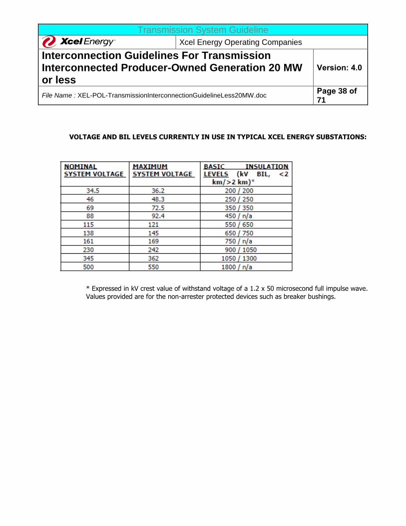
Transmission System Guideline
Xcel Energy Operating Companies
Interconnection Guidelines For Transmission Interconnected Producer-Owned Generation 20 MW or less
Version: 4.0
File Name : XEL-POL-TransmissionInterconnectionGuidelineLess20MW.doc Page 38 of 71
VOLTAGE AND BIL LEVELS CURRENTLY IN USE IN TYPICAL XCEL ENERGY SUBSTATIONS:
* Expressed in kV crest value of withstand voltage of a 1.2 x 50 microsecond full impulse wave. Values provided are for the non-arrester protected devices such as breaker bushings.
Transmission System Guideline
Xcel Energy Operating Companies
Interconnection Guidelines For Transmission Interconnected Producer-Owned Generation 20 MW or less
Version: 4.0
File Name : XEL-POL-TransmissionInterconnectionGuidelineLess20MW.doc Page 39 of 71
IV. ALTERNATIVE ENERGY INTERCONNECTIONS
Certain requirements of the Interconnection Guidelines do not apply for Alternative Energy interconnections due to the operational characteristics of the generator. The following alternative energy interconnections
are subject to specific interconnection requirements due to the operating characteristics of the generation.
A. INVERTER CONNECTED GENERATION
Inverter Connected Generation is normally energy supplied by photovoltaic sources, fuel cells, or other
energy supply, which requires a conversion from DC to AC to connect to the Xcel Energy transmission system. These systems must adhere to the standards for harmonics, flicker, and voltage. The protection
and design for Photovoltaic Systems must meet IEEE Standards C37.90, C37.90.2, C37.90.3 and ANSI/IEEE Standard 519, ANSI/IEEE Standard 929 and the NEC. A good companion book to the NEC is the
“Photovoltaic Power Systems and National Electric Code” booklet. This booklet is published by the Photovoltaic Design Assistance Center. Another booklet, “Interim Qualification Tests and Procedures for
Terrestrial Photovoltaic Thin-Film Flat-Plate Modules” (ANSI/IEEE 928), is also available from the
Photovoltaic Design Assistance Center.
B. WIND ENERGY GENERATION
Wind generation systems typically use induction generators. Reactive power supplies for induction generators may pose difficult problems. The installation of capacitors or dynamic voltage control devices to
mitigate reactive power problems and allow higher power factor operation must be studied on an individual
basis. In general, the wind energy plant cannot trip off-line for faults remote from the point of interconnection. Nor can the behavior of the wind energy plant cause other generating units to trip off-line.
There may be specific Reliability Council requirements that must also be met for wind generation.
Trip-out, commutation failure, short circuit, or other malfunction at one turbine, on the generator’s or Xcel Energy’s collector system serving a set of turbines, or at a point of interconnection, shall not cause
cascading or sympathetic trip-out of other generating units within generator’s development – either local or
remote – unless required to prevent damage to electrical facilities, or to isolate faulty devices, equipment or circuits.
Wind energy plants sometimes will cause a significant voltage variation as the MW output of the plant
changes in response to varying wind input conditions. However, protective systems must be installed so
this variation is not passed on to the Xcel Energy transmission system. In general, the voltage variation at the point of interconnection should not vary more than 1.5% for voltage oscillations with periods of 15
seconds to 5 minutes.
Transmission System Guideline
Xcel Energy Operating Companies
Interconnection Guidelines For Transmission Interconnected Producer-Owned Generation 20 MW or less
Version: 4.0
File Name : XEL-POL-TransmissionInterconnectionGuidelineLess20MW.doc Page 40 of 71
V. ACCEPTANCE TESTING AND INSPECTION REQUIREMENTS
Xcel Energy requires all Generators proposing to interconnect to the Xcel Energy System be in compliance
with the applicable testing and/or performance requirements.
A. GENERAL
Prior to the actual operation of Producer-owned generation with the Xcel Energy System, all pertinent contracts must be signed and all equipment modifications must be complete. Producers are required to
demonstrate the correct operation of all interface protective and control devices to Xcel Energy. Xcel Energy shall define and witness, but is not responsible for performing this demonstration.
The Producer must provide detailed information on the protective relaying, metering, and control (including sync-check) equipment that will interface with the Xcel Energy System. This is usually provided on a relaying
and metering one-line (and possibly a three-line) diagram. Basic proposed AC and DC schematics or specification of logic might also be provided at this time. This information is required 90 days before the
Generator in-service date, along with a listing of the specific relays, etc., including information on the
manufacturer, model number, relay ranges, etc. Xcel Energy requires at least two sets of any design documentation packages sent. If any subsequent changes are made, the Producer shall provide Xcel Energy a
set of revised one-lines, schematics, construction drawings, etc. Based on this information, Xcel Energy will develop and deliver to the Producer the required demonstration test details within 30 days after receipt of
information from Producer. A coordination meeting shall be held with Xcel Energy and the Producer to clarify any questions that may exist before testing begins.
Scheduling of demonstration testing should be coordinated through Xcel Energy with a minimum of three (3) business days notice. All testing shall be completed at least seven (7) days prior to the planned in-
service date to provide time to resolve problems identified during testing. If no problems are identified then the equipment can be placed in service without delay. Based on the amount of generation and the type of
generation at the site, Xcel Energy may, at Xcel Energy’s sole discretion, require only a design and relay
settings review and not require a site visit. Producers shall be responsible for determining their own relay settings. At least 60 days before startup testing, the Producer must supply the proposed settings for the
relays, including support documentation (e.g. calculations, fault studies, time over-current relay coordination curves, etc.) for approval by Xcel Energy.
The Producer shall supply certified test reports for Xcel Energy’s required protective relaying, interlocks, and
any equipment directly connected to Xcel Energy’s System (Producer’s transformers and/or breakers).
Certified test reports shall be sealed by a registered Professional Engineer (P.E.). Xcel Energy’s personnel may require witnessing some or all of the tests, calibrations, and the relay setting applications. The final “as-built”
documentation, including all drawings and final “as left” relay settings, must be provided by the Producer to Xcel Energy no later than 90 days after commercial operation.
Xcel Energy document TCS-4 “Testing Criteria” provides the specific criteria that Xcel Energy uses for ensuring its electrical equipment is properly tested and checked out. Xcel Energy requires that the
Producer’s facilities that are an integral part of the Xcel Energy System, or may disrupt the Xcel Energy
Transmission System Guideline
Xcel Energy Operating Companies
Interconnection Guidelines For Transmission Interconnected Producer-Owned Generation 20 MW or less
Version: 4.0
File Name : XEL-POL-TransmissionInterconnectionGuidelineLess20MW.doc Page 41 of 71
system due to miss-operation or failure, must undergo a similar level of testing and checkout. The
demonstration testing indicated above is employed to ensure that the Producer has completed the appropriate testing and checkout. Specific regional requirements may apply and may be obtained from the
regional Xcel Energy representative by request.
The Producer must assign one qualified and proficient protection and controls person to be the main point
of contact throughout the commissioning phase of the project. This person should have adequate field experience as appropriate to the system they are working on (46 kV and above). This person’s experience
should include, but not be limited to polarity checks, phase-outs, relay calibration, and trip testing for multiple large projects. This person will also insure adherence to these Guidelines. The Producer must also
provide qualified electricians, technicians, and operators to perform the demonstration testing. The
Producer must supply all personal protective equipment and designate any procedures necessary to assure that safety precautions are taken while working near energized equipment.
Inspection and approval by Xcel Energy does not constitute a warranty or relieve the Producer of
responsibility for the operating condition or installation of the equipment, and may not be relied upon by
the Producer for that purpose. Once the facility is interconnected, Xcel Energy will retain the right to inspect the facility if the operation is suspected of causing problems for other Xcel Energy Producers or
customers and retains the right to inspect the facilities of the Producer at Xcel Energy’s discretion.
B. DEMONSTRATION
The Producer and Xcel Energy shall follow the following steps in assuring that the new facilities have been
adequately tested prior to energization.
1. CONSTRUCTION TESTING DOCUMENTATION REVIEW
The Producer must complete field-testing of all their electrical equipment prior to commissioning and
energization. This includes physical testing of equipment such as transformers and circuit breakers per the manufacturers’ recommendations. This testing also includes setting and testing of relays and control
systems per the manufacturers’ recommendations, as well as verifying Xcel Energy approved relay settings.
The extent of testing shall be consistent with the level of testing specified in the International Electrical Testing Association (NETA) or National Institute for Certification in Engineering Technologies (NICET) and
good utility practice. These tests shall be completed prior to demonstration testing as outlined in the following paragraph. Xcel Energy may require being a witness to some of these testing activities. Xcel
Energy will notify the Producer prior to the start of testing if witness testing is required. In some cases, review of these test reports shall constitute sufficient demonstration that proper testing has been
completed.
The Producer must submit reports for all tests performed for approval by Xcel Energy. All revisions and
changes found on field drawings shall be shown on the Producer drawing and copies provided to Xcel Energy for approval by Xcel Energy. A written record must be kept of all tests showing date, personnel
performing test, signature or initial of person completing tests, equipment or material tested, as-left results,
Transmission System Guideline
Xcel Energy Operating Companies
Interconnection Guidelines For Transmission Interconnected Producer-Owned Generation 20 MW or less
Version: 4.0
File Name : XEL-POL-TransmissionInterconnectionGuidelineLess20MW.doc Page 42 of 71
and type of testing equipment used by manufacturer, model type, and model serial number. The test sheets
must show all equipment nameplate data (including for all bushings and surge arresters). Two copies of the final test reports must be submitted. Three copies of application software and instruction books are to be
supplied to Xcel Energy along with the test reports.
The Producer must download settings and programs from each relay and programmable logic controller
after testing to retrieve all as-left-in-service settings, and shall copy these files onto a formatted 3.5" floppy disk or CD-ROM, or e-mail the data to Xcel Energy. For non-microprocessor-based relays, test sheets or
reports for each device are to be completely filled out. All relay setting sheets are to be checked against as-left settings on the corresponding relay device and signed as being complete by the responsible technical
person. The disks, test sheets, reports, and settings are to be labeled with equipment identification
numbers, relay type numbers, and relay device numbers and returned to Xcel Energy with the test reports. The address is provided in Section II. of these Guidelines.
2. DEMONSTRATION TESTS Demonstration tests must be employed to ensure that each of the required protection systems and
protective devices operate correctly. These tests are used to verify that the Producer has completed testing
as indicated in the preceding paragraph. These tests also verify synchronizing equipment and the proper operation of the Xcel Energy – Producer interface protective relays. Xcel Energy will produce the
demonstration test requirements and deliver them to the Producer. Upon performance and certification of the Demonstration, the Producer will be granted approval for operation of their generating equipment in
parallel with Xcel Energy’s System. Unsuccessful demonstration may lead to delays in the Producer facility in-service date. Xcel Energy and the Producer will develop an initial energization procedure at least two
weeks prior to energization. If deemed necessary by Xcel Energy, a meeting will be held on site within one
week of the energization date to discuss any particulars of the initial energization.
The actual demonstration requirements will depend upon the final, approved AC/DC schematics, relay settings, etc. This demonstration is intended to be non-destructive. However, Xcel Energy will not be liable
for any equipment damage or injury resulting from the use of these guidelines. It is the responsibility of
the Producer to demonstrate the operation of all protective devices in a safe manner and in a manner that does not adversely affect the Producer’s generator or any equipment on the Xcel Energy System. Xcel
Energy recommends that similar tests be performed for the Producer’s other relays to insure the adequacy of their generator’s protective relaying.
3. POST IN-SERVICE TESTS
These tests are employed for verification of correct relay connections under actual load conditions. This is commonly known as “load checking”. These checks are completed by directly measuring actual operating
quantities in differential, distance, and overcurrent relays. This also includes spot-checking of metering and
SCADA systems. Post in-service tests may also include online tests of substation equipment including insulating oil tests of power transformers and infrared-thermography testing.
Transmission System Guideline
Xcel Energy Operating Companies
Interconnection Guidelines For Transmission Interconnected Producer-Owned Generation 20 MW or less
Version: 4.0
File Name : XEL-POL-TransmissionInterconnectionGuidelineLess20MW.doc Page 43 of 71
C. FUTURE CHANGES IN REQUIREMENTS
From time to time new requirements for testing, reporting, equipment and/or performance are established by
MRO, SPP, WECC, NERC, etc., for interconnected generation. The Producer should take steps so it is notified of any changes by the applicable entity. If a Producer fails to comply with these requirements and Xcel Energy is
required to pay monetary penalties assessed to Xcel Energy as the control area entity responsible for regional
interconnected system reliability. Xcel Energy will bill the Producer for any monetary penalty resulting from the non-performance of the Producer.
D. PERFORMANCE OF TESTS
The Producer must test all wire, cable, electrical equipment, and systems installed by the Producer or connected by the Producer to assure proper installation, adjustment, setting, connection, and functioning. The Producer
must inform Xcel Energy of any equipment or system that fails testing or that is deficient in any matter. The
extent of testing where modifications are made to existing circuits shall be sufficient to check the entire trip/control/CT/VT path as if it were new. Xcel Energy will not be responsible for any damage to equipment or
material due to Producer’s inadequate, substandard, improper test procedures or test apparatus handling.
Xcel Energy reserves the option to assign its personnel to assist the Producer in checking out certain control
schemes where Xcel Energy concludes such assistance is necessary to meet the project schedule. If Xcel Energy should exercise this option, the Producer will be notified in advance of the extent of Xcel Energy's
involvement.
Xcel Energy also reserves the right to shut down testing activities if, in Xcel Energy's opinion or the opinion of Xcel Energy's designated representative, the Producer is using unsafe practices or is in violation of applicable
local, state, or federal safety regulations. Xcel Energy requires compliance with the most conservative of the
safety practices as provided by OSHA, NESC, or Xcel Energy's safety practices whenever work is being performed in an energized facility.
E. TESTING EQUIPMENT
The Producer must provide all equipment necessary to perform the tests required by Xcel Energy. A list of
testing equipment shall be submitted to Xcel Energy for approval prior to the beginning of the testing. Test instrument type (manufacturer, type, serial number) and associated calibration certifications shall be submitted
to Xcel Energy prior to the commencement of any testing. The equipment certification shall be renewed at least annually and shall be traceable to the National Bureau of Standards. Xcel Energy will review the list and notify
the Producer of any testing items that are not acceptable or are missing from the list. The Producer shall
correct this deficiency prior to the start of testing.
F. XCEL ENERGY SUPPLIED EQUIPMENT Any Xcel Energy supplied equipment that is factory calibrated (transducers, pressure switches, tuners, etc.)
shall be tested to verify calibration. The Producer may not modify calibration settings without authorization
Transmission System Guideline
Xcel Energy Operating Companies
Interconnection Guidelines For Transmission Interconnected Producer-Owned Generation 20 MW or less
Version: 4.0
File Name : XEL-POL-TransmissionInterconnectionGuidelineLess20MW.doc Page 44 of 71
from Xcel Energy. If equipment does not meet specifications, the Producer should notify Xcel Energy of the
problem immediately. Xcel Energy will then direct the Producer on how to proceed. If the Producer modifies factory settings without authorization, Xcel Energy will not be responsible for any costs associated with repair,
replacement, or re-calibration of the Producer’s equipment.
G. FINAL DESIGN/AS-BUILT DOCUMENTS
The Producer must at the time of demonstration testing have a complete set of construction drawings and documentation available. These documents should represent a complete set of information showing exactly how
the facility has been built and the logic behind how the control systems will operate. The documents shall include but are not limited to one-line diagrams, meter and relaying diagrams (M&R), AC and DC elementary
diagrams (schematic drawings), circuit lists, Programmable Logic Controller (PLC) and relay logic, and any other
appropriate or necessary information. Xcel Energy should be provided a duplicate copy of this documentation at least two weeks prior to demonstration testing. A coordination meeting with Xcel Energy should be held to
clarify any questions on documentation or testing requirements before demonstration testing begins.
H. GENERATOR PARAMETER DATA
1. SPP AND MRO
The Producer must provide to Xcel Energy the results of unit testing which will include, but not be limited to the generator gross and net dependable capability, gross and net reactive power capability, performance of
voltage regulator controls, performance of speed/load regulator controls, and excitation systems. This testing is a NERC requirement and should be conducted once the generator has attained commercial status
and the test schedule has been mutually agreed upon with Xcel Energy. MRO also requires the annual URGE test, referred to in Section I.11. Periodic updated testing may be required per the individual regional
requirements.
2. WECC
All transmission-connected generators must perform testing on initial startup consistent with the
requirements of the WECC Synchronous Unit Dynamic Testing and Model Validation prepared by the WECC Control Work Group and Modeling and Validation Work Group in February 1997. This document is available
on the WECC website at www.wecc.biz under Publications and Documents. A copy is also available from Xcel Energy upon request. Other applicable documents include the NERC/WECC Planning Standards
(Revisions 8/9/02, or latest), sections II.B, III.B, and III.C.
The testing shall provide:
a. Verification of reactive limits (5 years)
b. Proper performance of the dynamic control systems (5 years) c. Computer model data used for transient stability analysis, including excitation systems, voltage
regulators, turbine-governor systems, power system stabilizers, and other associated generation
equipment (5 years).
Transmission System Guideline
Xcel Energy Operating Companies
Interconnection Guidelines For Transmission Interconnected Producer-Owned Generation 20 MW or less
Version: 4.0
File Name : XEL-POL-TransmissionInterconnectionGuidelineLess20MW.doc Page 45 of 71
d. Verification of real power output (MW) capability (annually).
Generator Owners must perform these tests, at their cost, every year or 5 years as specified and must
provide this data to Xcel Energy and WECC. These tests result in WECC Generator Certification.
Transmission System Guideline
Xcel Energy Operating Companies
Interconnection Guidelines For Transmission Interconnected Producer-Owned Generation 20 MW or less
Version: 4.0
File Name : XEL-POL-TransmissionInterconnectionGuidelineLess20MW.doc Page 46 of 71
VI. OPERATION AND MAINTENANCE GUIDELINES The Producer may be connecting to the Xcel Energy system for one of five different reasons, which are listed
below:
a. The Producer is selling the plant output to Xcel Energy Commercial Operations (XEM) and the plant
will be dispatchable by XEM. b. The Producer is selling the output to XEM and the plant is not dispatchable by XEM (wind energy,
run of river hydro, etc.) c. The Producer is selling the output on the open market (a merchant plant) and the output of the
plant is scheduled to other entities outside Xcel Energy’s transmission control area.
d. The Producer is selling the output on the open market (a merchant plant) and the output of the plant is controlled or dispatched by another control area.
e. The Producer is selling the output on the open market (a merchant plant) and the Producer will be its own control area, as defined by NERC.
Each of the unique situations described above has its own operating and maintenance guidelines. General guidelines will be stated below, but any specific guidelines will be defined in the Interconnection Agreement
between the Xcel Energy operating companies and the Producer.
The guidelines listed below apply only to the situations described in (a) and (b) above. The Operation and Maintenance Guidelines for (c) through (e) above will have to be defined in the Interconnect Agreement for that
generator interconnection. The Producer shall operate within the applicable guidelines of this document and
any other specific requirements as stated in the Interconnect Agreement, the Power Purchase Agreement, or the Ancillary Services Agreement.
A. NORMAL CONDITIONS
The Producer must operate according to the instructions and approval given by the Xcel Energy Transmission
Control Center personnel:
1. All schedules must be pre-approved prior to implementation. Usually the implementation notification will occur at specified intervals.
2. All generators operating in manual or automatic mode as requested. 3. The Producer has twenty-four hour support available.
B. ABNORMAL CONDITIONS Xcel Energy reserves the right to open the interconnection for any of the following reasons:
1. Xcel Energy line maintenance work on Xcel Energy System.
2. Xcel Energy System emergency.
3. Inspection of a Producer's generating equipment and protective equipment reveals a hazardous condition.
Transmission System Guideline
Xcel Energy Operating Companies
Interconnection Guidelines For Transmission Interconnected Producer-Owned Generation 20 MW or less
Version: 4.0
File Name : XEL-POL-TransmissionInterconnectionGuidelineLess20MW.doc Page 47 of 71
4. Failure of the Producer to provide maintenance and testing reports when required.
5. Producer's generating equipment interferes with other Xcel Energy customers or producers or with the operation of Xcel Energy System.
6. Producer has modified the generating equipment that affects Xcel equipment without the
knowledge and approval of Xcel Energy or has not installed Xcel required protective devices. 7. Parallel operation of any unapproved Producer generating equipment.
8. Personnel or public safety are threatened. 9. Producer fails to comply with applicable OSHA Safety Tagging and Lockout requirements.
Changes to the Xcel Energy System or the addition of other producers with generation in the vicinity may
require modifications to the interconnection protective devices. If such changes are required, the Producer may
be subject to future charges for these modifications.
C. ENERGIZATION OF XCEL ENERGY EQUIPMENT BY THE PRODUCER The Producer must not energize a de-energized Xcel Energy circuit (unless specifically authorized and requested
by Xcel Energy). The Producer must install the necessary control devices on the facility’s equipment to prevent
the energization of a de-energized Xcel Energy circuit by the Generator. Connection may be accomplished only by synchronization with the Xcel Energy System via synchronizing relays installed by the Producer. Failure to
observe this requirement will result in the immediate disconnection of the generator.
D. DISCONTINUATION OF OPERATION
Producers must discontinue parallel operation when requested by Xcel Energy:
1. To facilitate maintenance, test, or repair of Xcel Energy’s facilities. Xcel Energy will coordinate this with each Producer;
2. During system emergencies;
3. When a generator is interfering with other Xcel Energy customers or producers on the system; 4. When an inspection of a generator reveals either a condition hazardous to Xcel Energy’s System or
personnel or a lack of scheduled maintenance or maintenance records for equipment necessary to protect Xcel Energy’s System.
E. MAINTENANCE NOTIFICATION The Producer must notify Xcel Energy or the ISO as provided for in the applicable OATT of any unusual
conditions including, but not limited to the following:
1. Partial operating capability due equipment limitations and fuel shortages. 2. Scheduled outage periods and return to service expectations. Return to service notification must be
updated daily to reflect the recent progress or the lack of progress.

Transmission System Guideline
Xcel Energy Operating Companies
Interconnection Guidelines For Transmission Interconnected Producer-Owned Generation 20 MW or less
Version: 4.0
File Name : XEL-POL-TransmissionInterconnectionGuidelineLess20MW.doc Page 48 of 71
F. MAINTENANCE
Interconnection protective devices owned by the Producer should be maintained and inspected according to manufacturer recommendations, NERC, and/or industry standards. Procedures must be established for visual
and operational inspections. Provisions should be established for equipment maintenance and testing.
Equipment should include, but not be limited to:
1. Circuit Breakers 2. Protective Relays
3. Control Batteries
Xcel Energy maintains the right to review the maintenance, calibration, and operation data of all protective
equipment for protecting Xcel Energy facilities, customers, and other producers. The Producer is responsible for providing the necessary test accessories (such as relay test plugs, instruction manuals, wiring diagrams, etc.)
required to test these protective devices. Verification testing may include the tripping of the intertie breaker. If Xcel Energy performs work on the premises of the Producer, Xcel Energy operating personnel may make an
inspection of the work area. If hazardous working conditions are detected, the Producer must correct the
unsafe conditions before Xcel Energy personnel will perform their work.
G. DESIGN CHANGES AFTER COMMERCIAL OPERATION Any modifications to the Generator requiring Xcel Energy protective relaying and interlocks after the date of
commercial operation must be reviewed and approved by Xcel Energy prior to implementing any changes. Demonstration of Relay Calibration, Trip Tests, and On-Line Tests may be required depending on the extent of
the design change. Setting changes of any interconnection protection or synchronizing device must be approved
by Xcel Energy with a hard copy of the changes forwarded to the designated Xcel Energy representative. Any "Field Modification" or "As Built" AC/DC protection and synchronizing schematics associated with any Xcel
Energy required interconnection device must be forwarded to the designated Xcel Energy representative.
H. OPERATING DATA SUBMITTALS
The Producer must provide operating data and equipment modeling to Xcel Energy and/or the appropriate regional reliability organization to support the following:
1. NERC compliance program(s). 2. Regional Reliability Organization compliance program(s).
3. Federal, state and local regulatory programs.
I. OPERATIONAL LOG Producers must maintain an operating log at each generating facility indicating changes in operating status
(available or unavailable), maintenance outages, trip indications, or other unusual conditions found upon
inspection.
Transmission System Guideline
Xcel Energy Operating Companies
Interconnection Guidelines For Transmission Interconnected Producer-Owned Generation 20 MW or less
Version: 4.0
File Name : XEL-POL-TransmissionInterconnectionGuidelineLess20MW.doc Page 49 of 71
J. COMMUNICATION WITH XCEL ENERGY OPERATIONS
The Xcel Energy representative will provide the Producer with the names and telephone numbers of the Xcel Energy Control Center and Operations Coordination personnel responsible for Xcel Energy System at the
interconnection. The Producer will provide Xcel Energy with the names and telephone numbers of the personnel
with responsibility for operating the generator.
The contact(s) of the Producer should include at least one 24/7-telephone number. Contacts should be able to provide information on equipment status, explanation of events on the Producer’s equipment, and relay target
and alarm information when asked to do so by Xcel Energy personnel. Xcel Energy may choose to waive some of the communications requirements for smaller generating facilities. In addition, the Producer should contact
Xcel Energy whenever:
1. Problems with the generator are detected that could result in mis-operation of generator protection or
other generator equipment. 2. The Generator has tripped off-line during parallel operation with the Xcel Energy System.
3. Generator equipment problems result in an outage to a portion of the Xcel Energy System.
4. The Producer intends to initiate switching to parallel the Generator(s) and the Xcel Energy System. 5. The Producer intends to initiate switching to break the parallel interconnection between generator(s)
and the Xcel Energy System.
Transmission System Guideline
Xcel Energy Operating Companies
Interconnection Guidelines For Transmission Interconnected Producer-Owned Generation 20 MW or less
Version: 4.0
File Name : XEL-POL-TransmissionInterconnectionGuidelineLess20MW.doc Page 50 of 71
VII. GLOSSARY
AGC (Automatic Generation Control): An EMS based system that sends raise and lower instructions to the
governors of the generators in the control area for the purpose of matching the generation output to the area load. This is also known as Load Frequency Control (LFC).
Accredited: Generating capability recognized as meeting MRO requirements to satisfy a portion of a MRO member’s generating capacity obligation.
Alternating Current (AC): That form of electric current that alternates or changes in magnitude and polarity
(direction) in a regular pattern for a given time period.
Ampere: The unit of current flow of electricity. It is to electricity as the number of gallons per minute is to the
flow of water. One-ampere (A) flow of current is equal to one coulomb per second flow.
ANSI: American National Standards Institute.
Apparent Power: For single-phase power, the current in amperes multiplied by the voltage equals the
apparent power in volt-amperes (VA). Apparent power for 3-phase power equals the phase to neutral voltage multiplied by the line current multiplied by 3.
ATP (Alternate Transients Program): A digital computer modeling program that is typically utilized for
performing high frequency lightning and/or switching induced transient power system studies. This is similar to
EMTP and is not supported by the Electric Power Research Institute (EPRI).
Automatic: Self-acting, operated by its own mechanism when actuated by some impersonal influence as, for example, a change in current strength; not manual; without personal intervention.
Automatic Reclosing: A circuit breaker has automatic reclosing when means are provided for closing without manual intervention after it has tripped under abnormal conditions.
AVR (Automatic Voltage Regulator): A control system component associated with a generator’s field
excitation system and is used to automatically regulate and control the generator terminal voltage.
Capacity: The number of amperes of electric current a wire will carry without becoming unduly heated; the
maximum ability of a machine, apparatus, or device under existing service conditions; the load for which a transformer, transmission circuit, apparatus, station, or system is rated.
Circuit: A conducting path through which an electric current is intended to flow.
Circuit Breaker: A device for interrupting a circuit between separable contacts under normal or fault conditions. The interrupting ability of the device is normally rated or sized such that it exceeds the maximum
fault current that is available at the location of application.
Transmission System Guideline
Xcel Energy Operating Companies
Interconnection Guidelines For Transmission Interconnected Producer-Owned Generation 20 MW or less
Version: 4.0
File Name : XEL-POL-TransmissionInterconnectionGuidelineLess20MW.doc Page 51 of 71
Control Area: A control area is an electrical system bound by interconnect (tie-line) metering and telemetry
and which regulates its generation in order to maintain its interchange schedule with other systems, contributes to frequency regulation of the Interconnection, and fulfills its obligations and responsibilities in accordance with
NERC and reliability region (such as MRO, SPP, or WECC) requirements.
Control Contactors: Switching devices utilized to start or stop power system equipment, normally large
motors.
Current: A flow of electric charge measured in amperes (A).
CT (Current Transformer): A transformer intended for metering, protective, or control purposes and which is
designed to have its primary winding connected in series with a circuit carrying the current to be measured or controlled. A current transformer normally reduces current magnitudes to levels which can be handled by
control, protection, and metering equipment. A CT secondary circuit must never be open-circuited while energized.
Demand: The rate at which electric power is delivered to or by a system; normally expressed in kilowatts (kW), megawatts (MW), or kilovolt-amperes (kVA).
Disconnect: A device used to isolate a piece of equipment and which has a minimal ability or no ability to
interrupt current. A disconnect may be gang-operated (all poles switched simultaneously) or individually operated.
Dispatchable: Capable of having generator output (real and reactive power) adjusted (“dispatched”) upon request of the Xcel Energy Power System Operator. The adjustment normally includes the capability to start up
and shutdown generating units.
Dynamic Voltage Excursion: Transient change in system voltage magnitude, typically associated with a
condition following clearing a system short-circuit or fault.
Energy Losses: The general term applied to energy lost in the operation of an electrical system. Losses can be classified as Transformation Losses, Transmission Line Losses, or System Losses.
EMS (Energy Management System): The computer system Xcel Energy uses to provide real-time status and
remote control of its electrical transmission system.
EMTP (Electromagnetic Transients Program): A digital computer modeling program that permits the
analysis of the transient behavior of electrical networks. This program is presently supported by Electric Power Research Institute (EPRI).
ERO (Electric Reliability Organization): New electric reliability organization formed as prescribed in the Energy Policy Act of 2005. Expected to establish reliability standards, and provide for enforcement of those
standards.
Transmission System Guideline
Xcel Energy Operating Companies
Interconnection Guidelines For Transmission Interconnected Producer-Owned Generation 20 MW or less
Version: 4.0
File Name : XEL-POL-TransmissionInterconnectionGuidelineLess20MW.doc Page 52 of 71
FERC (Federal Energy Regulatory Commission): (Formerly the Federal Power Commission, or FPC.) FERC
is an independent body within the Department of Energy (DOE) regulating interstate transmission and the prices of electricity and natural gas. It also licenses hydroelectric projects and regulates interconnections,
construction work in progress, rates for wholesale Producers, utility accounting practices, and procedures.
Frequency: The number of alternating cycles occurring in a given interval of time (usually one second) in an
electric current or voltage. Frequency is commonly expressed in hertz (Hz).
Fuse: A short piece of conducting material of low melting point, which is inserted in a circuit for the purpose of opening the circuit when the current reaches a certain value.
Generator Capability Curves: The curves showing the real power output of a generator in relation to the reactive power output (also known as “D” curves).
Ground: A term used in electrical work in referring to the earth as the zero potential conductor or reference
plain. For safety purposes, circuits are grounded while any work is being done on or near a circuit or piece of
equipment in the circuit. This is usually called protective or safety grounding.
GSU (Generator Step-Up Transformer): A special purpose transformer that raises the voltage from the Producer’s generator up to the voltage of the interconnected system.
HCA (Host Control Area): Within MRO, scheduling areas and entities that do not operate a control area must
designate an HCA that is responsible for controlling the group’s load and for all scheduling errors that are made.
MRO will only deal with control areas and holds the control area responsible for all problems within that control area.
Hertz (Hz): The term denoting frequency. Historically, frequency was referred to as cycles per second.
IEEE: Institute of Electrical and Electronics Engineers, Inc.
Incoming Breaker: The Producer-owned breaker that connects the Xcel Energy source of power to the bus of the Producer.
Interconnection Facilities: The facilities required to make the physical connection between the
Interconnection Customer’s generation facility and the Xcel Energy transmission system. This may include new
substation and transmission facilities as well as other system upgrades to be owned by Xcel Energy.
Interconnection Facilities Study: A study conducted by the Transmission Provider or a third party consultant for the Interconnection Customer to determine a list of facilities, the cost of those facilities, and the
time required to interconnect the Generating Facility with the Transmission Provider’s Transmission System.
Interruption: A temporary discontinuance of the supply of electric power.
IPP (Independent Power Producer): An organization that is not a utility and that operates a power plant
that produces energy and sells it to a utility.
Transmission System Guideline
Xcel Energy Operating Companies
Interconnection Guidelines For Transmission Interconnected Producer-Owned Generation 20 MW or less
Version: 4.0
File Name : XEL-POL-TransmissionInterconnectionGuidelineLess20MW.doc Page 53 of 71
Island: A part of an interconnected system that may become isolated from the rest of the system during a system disturbance and start operating as a subsystem with its own generation, transmission, and distribution
capability. The islanded system and the main interconnected system may operate at different frequencies and
voltages.
ISO (Independent System Operator): Entities corporately separate from the owners of transmission and other power market participants approved by FERC to direct the operation of the transmission system.
ITC (Independent Transmission Company): Entities corporately separate from the owners of transmission
and other power market participants approved by FERC to direct the operation of the transmission system.
Kilovolt (kV): One thousand volts.
Kilovolt-Ampere (kVA): One thousand-volt ampere. See the definition for Apparent Power.
Kilowatt (kW): An electric unit of power that equals 1,000 Watts.
Lagging Power Factor: Occurs when reactive power flows in the same direction as real power.
Leading Power Factor: Occurs when reactive power flows in the opposite direction of real power.
Line Losses: Electrical energy converted to heat in the resistance of all transmission and/or distribution lines
and other electrical equipment.
Load Frequency Control (LFC): An EMS based system that sends raise and lower instructions to the governors of the generators in the control area for the purpose of matching the generation output to the area
load. This is also known as Automatic Generation Control.
MISO (Midcontinent Independent System Operator, Inc.): A FERC-approved ISO corporately
independent of Xcel Energy and to whom Xcel Energy has turned over the operations authority of its transmission system. The MISO will operate much of the transmission system from Minnesota, Wisconsin,
Iowa, Illinois, Pennsylvania, Kentucky, and Missouri.
MRO (Midwest Reliability Organization): A NERC reliability region.
Megavolt-Ampere (MVA): One million-volt ampere. See definition for Apparent Power.
Megawatt (MW): An electrical unit of power that equals one million watts.
NERC (North American Electric Reliability Corporation): NERC is a national organization responsible for establishing the operating and planning standards to assure the reliability of the electric grid. NERC is expected
to be replaced by the ERO. NERC Reliability Regions (SPP, WECC, and MRO) are expected to be replaced by Regional Entities (RE).
Transmission System Guideline
Xcel Energy Operating Companies
Interconnection Guidelines For Transmission Interconnected Producer-Owned Generation 20 MW or less
Version: 4.0
File Name : XEL-POL-TransmissionInterconnectionGuidelineLess20MW.doc Page 54 of 71
Non-Spinning Reserve: All unloaded generating capability not meeting the Spinning Reserve criteria but that
can be made fully effective in 10 minutes. This may include generation that shall be made available within 10 minutes by interrupting or curtailing loads or changing schedules.
OATT (Open Access Transmission Tariff): The FERC approved tariff for provision of transmission service to the Producer.
One-Line Diagram: A diagram in which several conductors are represented by a single line and in which
various devices or pieces of equipment are denoted by simplified symbols. The purpose of such a diagram is to present an electrical circuit or circuits in a simple way so that their function can be readily grasped.
On-Line Testing: Testing typically performed as part of commissioning a new generation facility, specifically as it pertains to energized equipment ultimately operating in parallel / interconnected with the power system.
Parallel Operation: The operation of a Producer-owned generator while connected to the utility's grid.
Parallel operation may be required solely for the operating convenience of the customer or producer, or for the
intentional interchange of power with the utility's grid.
Peak Load: The maximum electric power consumed in a stated period.
Point of Change of Ownership (PoCO): The point where the Producer’s Interconnection Facilities connect to Xcel Energy’s Interconnection Facilities.
Programmable Logic Controller (PLC): A special form of micro-processor based controller that uses a programmable memory to store instructions (“ladder logic”), and to implement functions such as logic
sequencing, timing, and arithmetic in order to control machines and processes.
Point of Delivery: See Point of Energy Exchange.
Point of Energy Exchange: The point in the delivery system where one party takes delivery of the energy
from the other party. This point is defined in the contract between Xcel Energy and the Interconnection Customer. It is usually the point where facility ownership changes. For transmission-connected producers, this
is usually at a location at the transmission voltage level. This is often referred to as the PoI or PoD.
Point of Interchange: See Point of Energy Exchange.
Point of Interconnection (POI): The point where the Interconnection Facilities connect to the Transmission
Provider's Transmission System.
Point of Metering: The point where metering equipment (meters, transducers, current transformers, voltage
transformers, etc.) is or will be installed to measure the power flow and energy exchange between Xcel Energy and the Producer.
Power (Actual, Active, or Real Power): The time rate of transferring or transforming energy or the power
that accomplishes work, measured in Watts.
Transmission System Guideline
Xcel Energy Operating Companies
Interconnection Guidelines For Transmission Interconnected Producer-Owned Generation 20 MW or less
Version: 4.0
File Name : XEL-POL-TransmissionInterconnectionGuidelineLess20MW.doc Page 55 of 71
Power Factor (PF): The ratio of actual power (kW) to apparent power (kVA).
Power Flow: One-way power flow is the condition where the flow of power is entirely into or out of the facility
of the Producer. Two-way power flow is the condition where the net flow of power may be either into or out of the facility depending on the operation of the generator and other Producer load.
Professional Engineer (P.E.): A licensed professional engineer registered with the appropriate state agency.
Programmable Logic Controller (PLC): A special form of micro-processor based controller that uses a
programmable memory too store instructions (“ladder logic”), and to implement functions such as logic
sequencing, timing, and arithmetic in order to control machines and processes. PSCAD: A transient analysis software program, similar to ATP and EMTP.
PSCAD - is a simulation program similar to EMTP and ATP programs. PSCAD is a registered trade mark of
Manitoba HVDC research center Inc.
PSS (Power System Stabilizer): Supplemental generator excitation device for the purpose of dampening
low-frequency system oscillations.
Producer: Party requesting to interconnect with Xcel Energy System.
Protection: All of the relays and other equipment that are used to open the necessary circuit breakers and
fuses to automatically clear or disconnect lines or equipment when trouble develops.
QF (Qualifying Facility): An IPP that has met the criteria to be certified by FERC as a Qualifying Facility and that has rights established by the PURPA of 1978.
Reactive Power (var): The power that oscillates back and forth between inductive and capacitive circuit elements without ever being used. The function of reactive power is to establish and sustain the electric and
magnetic fields that are required to perform useful work in AC systems.
Relay: A device that is operated by a variation in the condition of one electric circuit to affect the operation of another device in the same or in another electric circuit.
Remote Terminal Unit (RTU): A device installed at a substation or generation facility, and at an XE Operations Control Center, and is used to provide communication for remote control and indication of substation
or generation facility equipment from the XE Operations Control Center.
Regional Entities: Expected to replace the RRO after the implementation of the Electric Reliability
Organization.
RRO (Regional Reliability Organization): The entity under the authority of NERC/NAERO responsible for the reliable operation and use of the electric power system within a specific geographic region.
Transmission System Guideline
Xcel Energy Operating Companies
Interconnection Guidelines For Transmission Interconnected Producer-Owned Generation 20 MW or less
Version: 4.0
File Name : XEL-POL-TransmissionInterconnectionGuidelineLess20MW.doc Page 56 of 71
RTO (Regional Transmission Organization): Entities corporately separate from the owners of transmission
and other power market participants approved by FERC to direct the operation of the transmission system.
Scheduling Area: For MRO area entities, a scheduling area is similar to a control area in that a utility
schedules energy and provides capacity for a defined area. The utility operates a 24-hour control center and is recognized as a MRO Scheduling Area. Unlike a control area, a scheduling area does not have generators that
can follow the load in their area and are completely captured within one or more control areas. They must contract for load following services. Within MRO, a scheduling area must identify a Host Control Area.
Spinning Reserve: The amount of unloaded generating capability of a participant connected to and
synchronized with the interconnected system of the participants and ready to take load. The Spinning Reserve
allocated to any generator shall not exceed the amount of generation increase that can be realized in 10 minutes by that machine.
SPP (Southwest Power Pool, Inc.): A NERC reliability region. An organization of power suppliers in the
Western States that plans for power availability by coordinating power exchanges between members. SPP’s
current members include investor-owned companies such as Xcel Energy, municipal systems, and rural cooperatives. SPP has a Pool Wide Tariff under which Xcel Energy has placed the SPS operating area. This tariff
governs generator interconnection requests and provides network and point-to-point transmission service.
Station Power: The electric power used for the heating, lighting, air-conditioning and office equipment needs of the buildings on a Generation Facility’s site, and for operating the electric equipment that is on the
Generating Facility’s site.
Station Service: The electric energy needs of the Transmission Provider’s substation equipment.
Switch: A device for making, breaking, or changing the connections in an electric circuit.
System: The entire generating, transmitting, and distributing facilities of an electric system.
THD (Total Harmonic Distortion): A measure of the amount of the non-fundamental content that an electrical waveform contains. The non-fundamental (60 Hz) part consists of frequency components that are
integer multiples of the fundamental.
Transformer: An electric device, without continuously moving parts, in which electromagnetic induction
transforms electric energy from one circuit to one or more other circuits at the same frequency, usually with changes in the magnitudes of the voltage and current.
Transient Network Analysis (TNA): A digital computer modeling program that permits the analysis of the
transient behavior of electrical networks.
Transmission Owner: An entity that owns, leases, or otherwise possesses an interest in the portion of the
Transmission System at the Point of Interconnection and may be a Party to the Interconnection Agreement to the extent necessary.
Transmission System Guideline
Xcel Energy Operating Companies
Interconnection Guidelines For Transmission Interconnected Producer-Owned Generation 20 MW or less
Version: 4.0
File Name : XEL-POL-TransmissionInterconnectionGuidelineLess20MW.doc Page 57 of 71
Transmission Provider: The public utility (or its designated agent) that owns, controls, or operates
transmission or distribution facilities used for the transmission of electricity in interstate commerce and provides transmission service under the OATT. The Transmission Provider includes the Transmission Owner when the
Transmission Owner is separate from the Transmission Provider.
URGE (Uniform Rating of Generation Equipment) Test: A MRO area set of tests to confirm the abilities
and ratings of a generator located in the MRO area.
Utility Grade Relays: Relays that meet IEEE C37.90, C37.90.1, C37.90.2, and C37.90.3.
var: Volt-ampere reactive, see Reactive Power.
var Capability Testing: Testing performed with a generation facility interconnected with the XE power system
in order to verify or determine the generation facility's net reactive power (var) output and corresponding power factor, typically as measured at the POI.
Voltage: Electric potential or potential difference expressed in volts (V).
Volt-Ampere: A unit of apparent power (VA) in an alternating-current circuit.
VT (Voltage Transformer): A transformer intended for metering, protective, or control purposes and which is designed to have its primary winding connected either between the primary conductors to be measured or
between a conductor and ground. A voltage transformer normally reduces voltage magnitudes to levels which
can be handled by control, protection, and metering equipment. The historic term for a VT is potential transformer.
Watt-Hour: A unit of work or energy equivalent to the power of one Watt operating for one hour (Wh).
WECC (Western Electricity Coordination Council): a NERC reliability region. An organization of power suppliers in the Western States that plans for power availability by coordinating power exchanges between
members. WECC’s current members include investor-owned companies such as Xcel Energy, municipal systems, rural cooperatives, the Western Area Power Administration, Bonneville Power Administration, and the US Bureau
of Reclamation.
Wye or "Y" Connected Circuit (Star Connected): A three-phase circuit in which windings of all three
phases have one common neutral point connection.
Transmission System Guideline
Xcel Energy Operating Companies
Interconnection Guidelines For Transmission Interconnected Producer-Owned Generation 20 MW or less
Version: 4.0
File Name : XEL-POL-TransmissionInterconnectionGuidelineLess20MW.doc Page 58 of 71
VIII. REFERENCES
The following list of references has been utilized in preparation of this document and/or should be consulted for further information/clarification. When the following publications/standards are superseded by an approved
revision, the latest revision shall apply.
ANSI C2-2002, National Electrical Safety Code.
ANSI C84.1-1995 (R2005), Electric Power Systems and Equipment - Voltage Ratings (60HZ).
IEEE Std. C37.106TM –2003, IEEE Guide for Abnormal Frequency Protection for Power Generating Plants,
ANSI/ IEEE C37.90-1989, IEEE Standard for Relays and Relay Systems Associated with Electric Power Apparatus.
IEEE Std C37.90.1-2002TM – 2002, IEEE Standard for Surge Withstand Capability (SWC) Tests for Relays and Relay Systems Associated with Electric Power Apparatus.
IEEE Std C37.90.2TM-2004, IEEE Standard for Withstand Capability of Relay Systems to Radiated
Electromagnetic Interference from Transceivers.
IEEE Std C37.90.3-2001, IEEE Standard Electrostatic Discharge Tests for Protective Relays.
IEEE Std C37.95TM – 2002, IEEE Guide for Protective Relaying of Utility-Consumer Interconnections.
IEEE Std 80-2000, IEEE Guide for Safety in AC Substation Grounding.
IEEE Std-142-1991, IEEE Recommended Practice for Grounding of Industrial and Commercial Power Systems – IEEE Green Book (Color Book Series).
IEEE Std-242-2001, IEEE Recommended Practice for Protection and Coordination of Industrial and Commercial
Power Systems – IEEE Buff Book (Color Book Series).
IEEE Std-446-1995, IEEE Recommended Practice for Emergency and Standby Power Systems for Industrial and
Commercial Applications – IEEE Orange Book (Color Book Series).
IEEE 519-1992, IEEE Recommended Practices and Requirements for Harmonic Control in Electrical Power Systems.
IEEE 1453TM-2004, IEEE Recommended Practice for Measurement and Limits of Voltage Fluctuations and Associated Light Flicker on AC Power Systems
IEEE Std-1100-1999, IEEE Recommended Practice for Powering and Grounding Electronic Equipment – IEEE
Emerald Book (Color Book Series).

Transmission System Guideline
Xcel Energy Operating Companies
Interconnection Guidelines For Transmission Interconnected Producer-Owned Generation 20 MW or less
Version: 4.0
File Name : XEL-POL-TransmissionInterconnectionGuidelineLess20MW.doc Page 59 of 71
NERC Reference Document, Reliability Considerations for Integrating Non-Utility Generating Facilities with the Bulk Electric Systems, April 1987, North American Electric Reliability Council, Princeton, NJ 08540.
NERC Document, Integrating Non-Utility Generators - Reliability Considerations for Integrating Non-Utility Generating Facilities with the Bulk Electric Systems, January 1992, North American Electric Reliability Council,
Princeton, NJ 08540.
NERC/WECC Planning Standards September 1997.
NFPA 70- 2005, National Electrical Code
OSHA Safety Tagging and Lockout Procedures.
Standardization of Generation Interconnection Agreements and Procedures,” Order No. 2003, Fed. Reg. Vol. 68,
No. 160 (August 19, 2003).
WSCC Coordinated Off-nominal Frequency Load Shedding and Restoration Plan (Final Report November 25,
1970), prepared by the Under-frequency Issues Workgroup, WSCC Technical Studies Subcommittee.
Xcel Energy document "Physical Design Criteria for Substations"
Xcel Energy document TCS-3 "Transmission Criteria for Substations: Protective Relaying and Control"
Xcel Energy document TCS-4 “Testing Criteria”
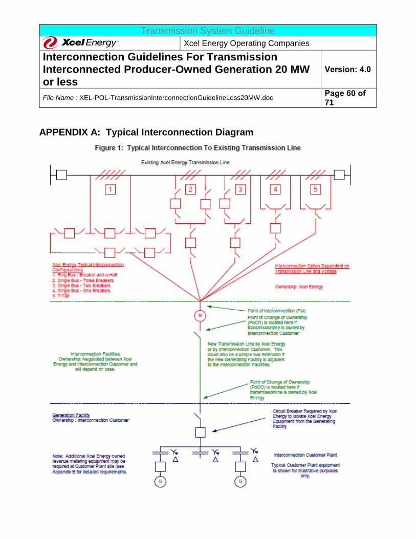
Transmission System Guideline
Xcel Energy Operating Companies
Interconnection Guidelines For Transmission Interconnected Producer-Owned Generation 20 MW or less
Version: 4.0
File Name : XEL-POL-TransmissionInterconnectionGuidelineLess20MW.doc Page 60 of 71
APPENDIX A: Typical Interconnection Diagram
Transmission System Guideline
Xcel Energy Operating Companies
Interconnection Guidelines For Transmission Interconnected Producer-Owned Generation 20 MW or less
Version: 4.0
File Name : XEL-POL-TransmissionInterconnectionGuidelineLess20MW.doc Page 61 of 71
APPENDIX B: Xcel Energy Metering and Telemetry Requirements
1. GENERAL
The information in Appendix B outlines the requirements that shall apply for interconnecting the Producer to the Xcel Energy System. In those cases where the Power Purchase Agreement, Interconnection Agreement, or
Ancillary Services Agreement provisions differ from these requirements, the contract provisions shall take
precedence.
The meter installation will be capable of measuring Real Energy (Watts, kW, or MW), Reactive Energy (vars, kvars, or Mvars), Voltage (V or kV), Current (A), Watt-hours (Whr, kWhr, or MWhr), and var-hours (var-hours,
kvar-hours, or Mvar-hours). The metering shall have memory capable of a minimum of 4-channel, hourly data
recording for 60 days. Additional channels for data recording may be required at the discretion of Xcel Energy. High side or low side metering (with either a fixed billing Transformer Loss Compensation (TLC), a Meter
Programmed or MV90 software calculated TLC will be used when a Producer owns the facility transformer. Low side metering may be required when the unit of the Producer is embedded into another entity’s electric system
such as in an industrial plant. In this case, there may be a “Transformer Loss Compensation” adjustment within
the metering. The metering installation shall have remote dial-up metering, and associated transducers, instruments transformers (CTs, VTs) will be specified and owned by Xcel Energy, but could be purchased and
installed by the Producer or XE, as identified during the project design phases, and determined on a case-by-case basis. Xcel Energy will furnish meter and programs according to Xcel Energy specifications.
2. METERING ACCURACY, TESTING, AND REPAIR
A. METERING ACCURACY – REVENUE METERING
The metering shall have an accuracy of + or – 0.5%. Any current or voltage transformers that are used for
metering will adhere to the “Accuracy Classifications for Metering” listed in ANSI C57.13 Xcel Energy requires 3-element metering accuracy for all circuits; however, 2-element metering may be acceptable
where necessary. The Voltage Transformers (VT) and Current Transformers (CT) must be metering
accuracy class devices. Metering CTs and VTs are required to be independent of the protection system CTs. As long as the burden is not determined by Xcel Energy to be excessive, additional secondary windings on
the VTs can be used for other purposes such as protective relaying. All of these VT secondary supplies used for non-revenue metering purposes (e.g. relaying) shall be separately fused from the metering VT
secondary supplies.
All voltage and current transformers used for interconnect metering with continuous flows less than 20% of
full scale nameplate rating of the current transformers shall conform to 0.15% metering accuracy class or
better. All current transformers shall conform to ANSI metering accuracy class 0.3% for Burdens B0.1 thru
B1.8 and shall have a continuous current thermal rating factor (TRF) sized appropriately for the application.
All voltage transformers shall meet ANSI metering accuracy class 0.3% for all standard burdens. The
current transformers and voltage transformers used to meter bi-directional power flow shall meet ANSI
Transmission System Guideline
Xcel Energy Operating Companies
Interconnection Guidelines For Transmission Interconnected Producer-Owned Generation 20 MW or less
Version: 4.0
File Name : XEL-POL-TransmissionInterconnectionGuidelineLess20MW.doc Page 62 of 71
C57.13 requirements for instrument transformers. MW and Mvar transducers shall be 3-element
transducers with an accuracy of 0.2% or better. Note that the metering used for local (panel) and remote
(SCADA) indication and monitoring purposes does not typically need to conform to the higher accuracy requirements of the revenue metering, and are typically supplied off of the relaying accuracy CTs (bushing
CTs), CVTs, etc.
B. PERIODIC TESTING
The metering equipment shall be tested periodically, and re-calibrated to maintain the required accuracy.
The meter testing frequency shall at a minimum be based on current Xcel Energy Practices. Xcel Energy’s
present testing practices are based on the type of metering situation and the jointly agreed to requirements of both parties involved. Typically, the metering equipment at non-Xcel Energy generation sites is tested
annually. The Producer, at its option, may participate in the periodic testing. The party performing the testing must notify the witness party at least a week in advance, preferably more. If the proposed date is
not acceptable, then an alternative time acceptable to both parties must be worked out. The owner of the meter shall analyze and distribute any maintenance, repair, and test results to all parties receiving the
meter readings per the request of such parties.
C. METER AND TELEMETRY EQUIPMENT REPAIR
The owner of the metering and telemetry equipment is responsible for ensuring that the equipment is
adequately maintained and is repaired within a reasonable time after a failure is detected. The repair or
replacement of a bad meter must be completed within 24 hours after it has been detected. If the metering cannot be repaired within that time, Xcel Energy may require that the Interconnection Customer cease all
generation until the meter has been repaired. All changes, repairs, and replacements of the meter must be coordinated with the Xcel Energy Meter Department.
3. METERING AND TELEMETRY FUNCTION REQUIREMENTS
The meter and telemetry requirements define Xcel Energy’s required functionality for meters, metering related
equipment (telephone lines, current transformers, voltage transformers, etc.), and telemetry equipment (Remote Terminal Units [RTUs], transmitters, receivers, etc.). Three major factors generally determine the type
of metering and telemetry required:
a. The type and size of the customer’s generating equipment.
b. The location of the customer on the Xcel Energy System. c. The manner in which the installation will operate (one-way vs. two-way power flow).
Each request will be handled individually, and Xcel Energy will solely determine the metering and telemetry
modifications and/or additions required. Xcel Energy will work with the customer to achieve an installation that
meets the requirements of both the customer and Xcel Energy. The metering requirements and cost responsibility will be stated in the Interconnection Agreement.
Transmission System Guideline
Xcel Energy Operating Companies
Interconnection Guidelines For Transmission Interconnected Producer-Owned Generation 20 MW or less
Version: 4.0
File Name : XEL-POL-TransmissionInterconnectionGuidelineLess20MW.doc Page 63 of 71
If the generating facility is outside Xcel Energy’s control area, the utility within whose control area the generator
resides may have specific metering and telemetry requirements to which the Producer must adhere. Upon the start of the Facilities Study, Xcel Energy will notify the customer of any other utility who may need to be
involved in the metering and telemetry design and approval. If the generator is not within either Xcel Energy’s
service territory or Xcel Energy’s control area, the following metering and telemetry requirements may not apply
A. MEASURED VALUES AND METERING REQUIRED FOR GENERATING STATIONS WITH A NET OUTPUT CAPACITY GREATER THAN OR EQUAL TO 20 MW
1. Real Power Flow (Watts, kW, or MW). 2. Reactive Power Flow (vars, kvars, or Mvars).
3. Voltage at the point of connection to the Xcel Energy System at Xcel Energy’s discretion. 4. Amps at the point of connection with the Xcel Energy System.
5. Remote Terminal Unit or Data Link to telemeter all measured values to Xcel Energy’s Energy Management System. Recording and communication of the data to Xcel Energy’s EMS through a
dedicated communication medium. If the customer participates in the ancillary services market,
recording and communicating every six seconds or less is required.
B. METERING CONFIGURATION
The meter installation will be capable of measuring Real Energy (Watts), Reactive Power (vars), Voltage
(V), Current (A), Watt-hours, and var-hours. The metering shall have memory capable of a minimum of 4-
channel, hourly data recording for 60 days. Additional channels for data recording may be required at the discretion of Xcel Energy.
The Typical Metering Installation (see Figure B-1) will be used when Xcel Energy serves the load
requirements of the Producer directly. At least two meters will be utilized; one meter will be used to
measure the total power into or out of the facility. The Net meter will typically be on the high side of the generator step up transformer at the point of interconnection (Net facility POI). The other meter(s) will be
located on each of the generator(s). The Generation meters will be totalized to give the total output of the generation (Gross Generation). The difference in the Net Facility POI meter and the Gross Generation
metering is the load of the facility (house power load, all other loads and losses not associated with the power production process). The load of the facility will be billed using the current billing rates on file with
PUC or PSC.
When Xcel Energy is not the retail supplier, the metering for the load requirements for the Producer will be
determined by the retail service provider (see Figure B-2).
Each specific situation will be evaluated for cost effective metering.
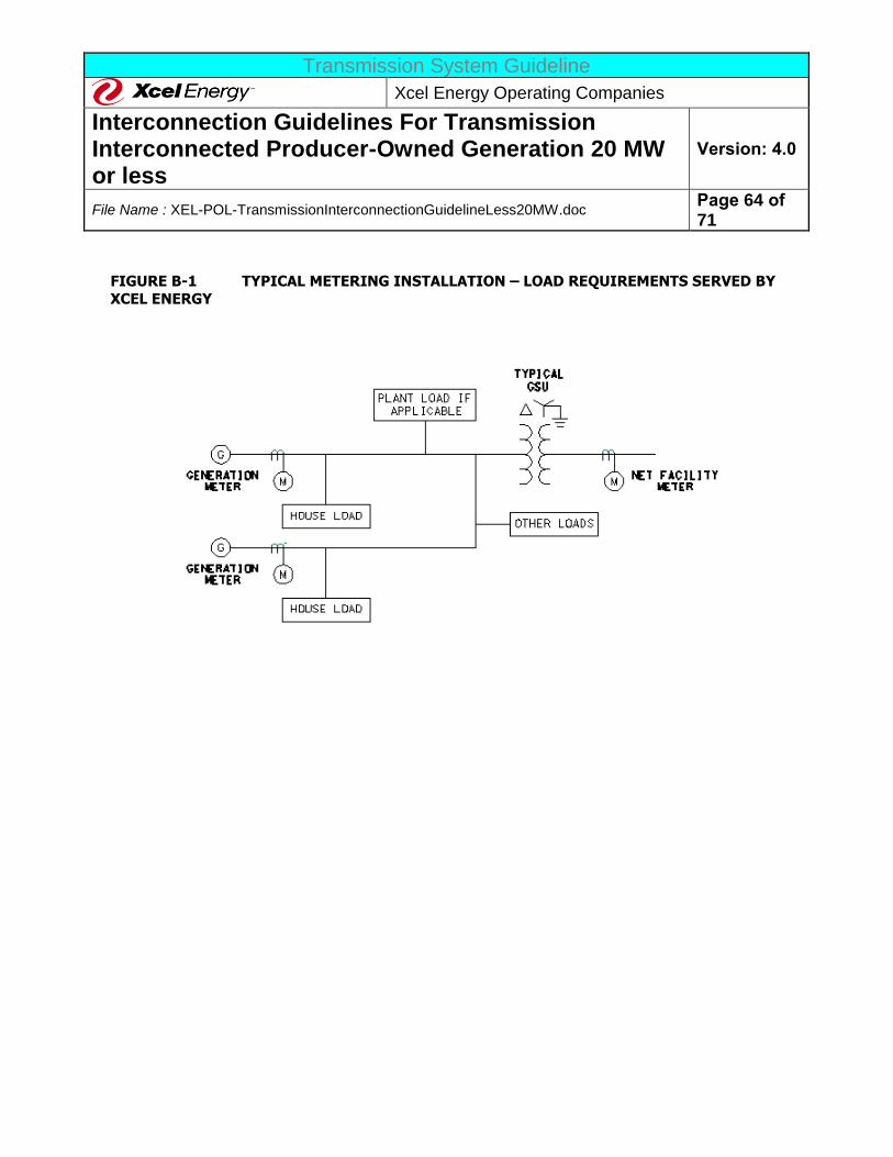
Transmission System Guideline
Xcel Energy Operating Companies
Interconnection Guidelines For Transmission Interconnected Producer-Owned Generation 20 MW or less
Version: 4.0
File Name : XEL-POL-TransmissionInterconnectionGuidelineLess20MW.doc Page 64 of 71
FIGURE B-1 TYPICAL METERING INSTALLATION – LOAD REQUIREMENTS SERVED BY
XCEL ENERGY
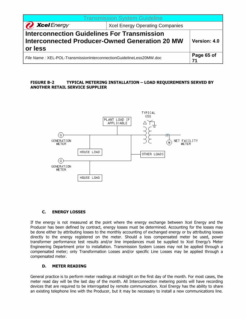
Transmission System Guideline
Xcel Energy Operating Companies
Interconnection Guidelines For Transmission Interconnected Producer-Owned Generation 20 MW or less
Version: 4.0
File Name : XEL-POL-TransmissionInterconnectionGuidelineLess20MW.doc Page 65 of 71
FIGURE B-2 TYPICAL METERING INSTALLATION – LOAD REQUIREMENTS SERVED BY ANOTHER RETAIL SERVICE SUPPLIER
C. ENERGY LOSSES
If the energy is not measured at the point where the energy exchange between Xcel Energy and the
Producer has been defined by contract, energy losses must be determined. Accounting for the losses may be done either by attributing losses to the monthly accounting of exchanged energy or by attributing losses
directly to the energy registered on the meter. Should a loss compensated meter be used, power transformer performance test results and/or line impedances must be supplied to Xcel Energy’s Meter
Engineering Department prior to installation. Transmission System Losses may not be applied through a
compensated meter; only Transformation Losses and/or specific Line Losses may be applied through a compensated meter.
D. METER READING
General practice is to perform meter readings at midnight on the first day of the month. For most cases, the
meter read day will be the last day of the month. All Interconnection metering points will have recording devices that are required to be interrogated by remote communication. Xcel Energy has the ability to share
an existing telephone line with the Producer, but it may be necessary to install a new communications line.

Transmission System Guideline
Xcel Energy Operating Companies
Interconnection Guidelines For Transmission Interconnected Producer-Owned Generation 20 MW or less
Version: 4.0
File Name : XEL-POL-TransmissionInterconnectionGuidelineLess20MW.doc Page 66 of 71
The communications circuit cost (telephone lines, telephone charges, etc.) to allow remote reading of the
meter at a non-Xcel Energy facility is the responsibility of the Producer. Other communication options may be available for meter data retrieval, depending on service territory.
4. VOICE DISPATCH CIRCUIT
There shall be a voice communications circuit between the Producer’s facility and/or Producer’s dispatch center
and the Xcel Energy System Control Center. If the facility plant operators are not located on the plant site, then
the circuit must be terminated at the actual location of the plant operators. The circuit may be a leased line or may be a dialup circuit. If the circuit is a leased circuit, this circuit is to be ordered by the Producer. This circuit
will be a type 428 non-dialable pair, also known as an OSPA two-wire circuit.
5. PRODUCER FACILITY NET GENERATION OUTPUT TELEMETRY AND CONTROL
The design, purchase, installation, testing, maintenance, and replacement of the remote generation control and telemetry equipment and circuits from a Producer's facility to Xcel Energy’s EMS Dispatch Center will be the
responsibility of Xcel Energy or their designated representative. The direct costs will be charged to the Producer.
A. GENERATION TELEMETERING
All Producers will have telemetering equipment installed at the Producer’s facility, and receiving equipment at Xcel Energy’s Operations Control Center (EMS Dispatch). This will typically include a telemetry Remote
Terminal Unit (RTU) and meters (or transducers) that utilize the same Xcel Energy-supplied CTs and VTs used for the separate revenue meters. A separate dedicated communication circuit (e.g., leased line, etc.)
will be required with this telemetry equipment.
B. XCEL ENERGY REQUIRED TELEMETRY POINTS
The table below provides the general telemetry and LFC/AGC requirements. As each installation is unique,
the requirements may differ slightly depending on the type of generator interconnection as stated in Section VII. The Interconnect Agreement, Power Purchase Agreement, or Ancillary Services Agreement may contain
certain requirements that must be met in addition to or in place of the typical ones listed below.
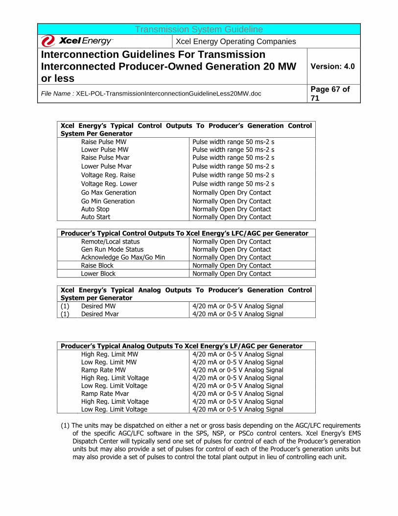
Transmission System Guideline
Xcel Energy Operating Companies
Interconnection Guidelines For Transmission Interconnected Producer-Owned Generation 20 MW or less
Version: 4.0
File Name : XEL-POL-TransmissionInterconnectionGuidelineLess20MW.doc Page 67 of 71
Xcel Energy’s Typical Control Outputs To Producer’s Generation Control
System Per Generator
Raise Pulse MW Pulse width range 50 ms-2 s Lower Pulse MW Pulse width range 50 ms-2 s
Raise Pulse Mvar Pulse width range 50 ms-2 s
Lower Pulse Mvar Pulse width range 50 ms-2 s
Voltage Reg. Raise Pulse width range 50 ms-2 s
Voltage Reg. Lower Pulse width range 50 ms-2 s
Go Max Generation Normally Open Dry Contact
Go Min Generation Normally Open Dry Contact
Auto Stop Normally Open Dry Contact Auto Start Normally Open Dry Contact
Producer’s Typical Control Outputs To Xcel Energy’s LFC/AGC per Generator
Remote/Local status Normally Open Dry Contact Gen Run Mode Status Normally Open Dry Contact
Acknowledge Go Max/Go Min Normally Open Dry Contact
Raise Block Normally Open Dry Contact
Lower Block Normally Open Dry Contact
Xcel Energy’s Typical Analog Outputs To Producer’s Generation Control System per Generator
(1) Desired MW 4/20 mA or 0-5 V Analog Signal
(1) Desired Mvar 4/20 mA or 0-5 V Analog Signal
Producer’s Typical Analog Outputs To Xcel Energy’s LF/AGC per Generator
High Reg. Limit MW 4/20 mA or 0-5 V Analog Signal
Low Reg. Limit MW 4/20 mA or 0-5 V Analog Signal Ramp Rate MW 4/20 mA or 0-5 V Analog Signal
High Reg. Limit Voltage 4/20 mA or 0-5 V Analog Signal Low Reg. Limit Voltage 4/20 mA or 0-5 V Analog Signal
Ramp Rate Mvar 4/20 mA or 0-5 V Analog Signal
High Reg. Limit Voltage 4/20 mA or 0-5 V Analog Signal Low Reg. Limit Voltage 4/20 mA or 0-5 V Analog Signal
(1) The units may be dispatched on either a net or gross basis depending on the AGC/LFC requirements of the specific AGC/LFC software in the SPS, NSP, or PSCo control centers. Xcel Energy’s EMS
Dispatch Center will typically send one set of pulses for control of each of the Producer’s generation units but may also provide a set of pulses for control of each of the Producer’s generation units but
may also provide a set of pulses to control the total plant output in lieu of controlling each unit.
Transmission System Guideline
Xcel Energy Operating Companies
Interconnection Guidelines For Transmission Interconnected Producer-Owned Generation 20 MW or less
Version: 4.0
File Name : XEL-POL-TransmissionInterconnectionGuidelineLess20MW.doc Page 68 of 71
C. LOAD CONTROL/RELAYING/COMMUNICATION CABINETS REQUIREMENTS
For most installations, Xcel Energy will provide cabinets that contain equipment for load control, telemetry, communications, and transmission line protective relaying that will be installed in the control room of the
Facility of the Producer. Typically this equipment will be installed in two separate cabinets, each with dimensions of 36” X 36” X 90”. A third cabinet, also 36” X 36” X 90”, will contain all interface terminal
blocks and will act as a demarcation point of ownership between the Producer’s equipment and wiring and
Xcel Energy’s relaying, load control, and telemetry equipment. This interface cabinet may also contain a box mounted to the front that houses Xcel Energy’s revenue metering. Xcel Energy requires that space be
allotted to install these three cabinets in the Producer’s control house or electrical room. All cabinets are free standing and will be mounted side by side. The cabinets have rear-swinging doors and will require both
front and rear access.
The Producer will provide all cables that extend from the interface cabinet to the equipment of the Producer
located in the switchyard and to the turbine control system. These cables will be identified on a cable schedule provided to the Producer by Xcel Energy’s System Engineering. The cable material shall meet or
exceed Xcel Energy’s cable specification. In most cases, Xcel Energy will provide communication cable(s)
(possibly fiber optic cable) from the interface cabinet to the transmission line dead-end tower, or a location designated by Xcel Energy, in the switchyard of the Producer. The Producer shall provide all ditching and
conduit required for the installation of this cable. This cable shall remain the property of Xcel Energy.
AC and DC sources will be required to operate the protective relaying, load control, and communication equipment. Separately fused DC circuits are required for the primary and backup relaying. Load control
telemetry equipment and communication equipment will require separately fused DC circuits.

Transmission System Guideline
Xcel Energy Operating Companies
Interconnection Guidelines For Transmission Interconnected Producer-Owned Generation 20 MW or less
Version: 4.0
File Name : XEL-POL-TransmissionInterconnectionGuidelineLess20MW.doc Page 69 of 71
Appendix C: Additional Wind Collector System Connection Requirements In addition to the requirements of the main document, this appendix contains some additional requirements
that the customer’s interconnection must adhere to. These requirements are specific to Xcel Energy owned Wind Collector Feeders (34.5 kV).
1. FAULT CLEARING REQUIREMENTS All interconnections located less than six conductor miles from the originating Xcel Energy substation shall be protected with either a fuse, or a re-closer (or breaker) with instantaneous tripping enabled. Faults located in
this region must be cleared quickly to minimize the impact to Xcel Energy’s system. For the available fault current levels at the six-mile point on the feeder, the customer’s fuse or re-closer must clear the fault in a
maximum clearing time of five cycles. If the customer’s fuse cannot meet this requirement, then the customer
must install a re-closer with protective relays to meet the five-cycle maximum clearing time requirement.
Interconnections located past the six-mile point on the feeder will be allowed to have fuses or re-closers that clear faults within 15 cycles at the available fault current level at the tail-end of the customer’s collector system.
Xcel Energy reserves the right to modify the future configuration of these collector feeders. Future re-configurations that result in an interconnection being located within six conductor miles of the originating
substation will require the customer to meet the fault clearing requirements listed above.
Customers that have a re-closer as their fault-clearing device must, upon request from Xcel Energy, provide faults records in a timely manner. If these fault records are required to troubleshoot an operating problem,
these records will be needed within 48 hours of being requested.
2. AUTOMATIC RE-CLOSING Xcel Energy’s substation feeder breaker will be set to issue one automatic re-close approximately 15 to 30
seconds after it opens. The customer’s equipment must be designed to handle this automatic re-close without incurring damage to the wind generators.
3. INTERCONNECTION CONFIGURATION Two diagrams are attached that show example configurations of the interconnection point. Detailed design drawings are available upon request.
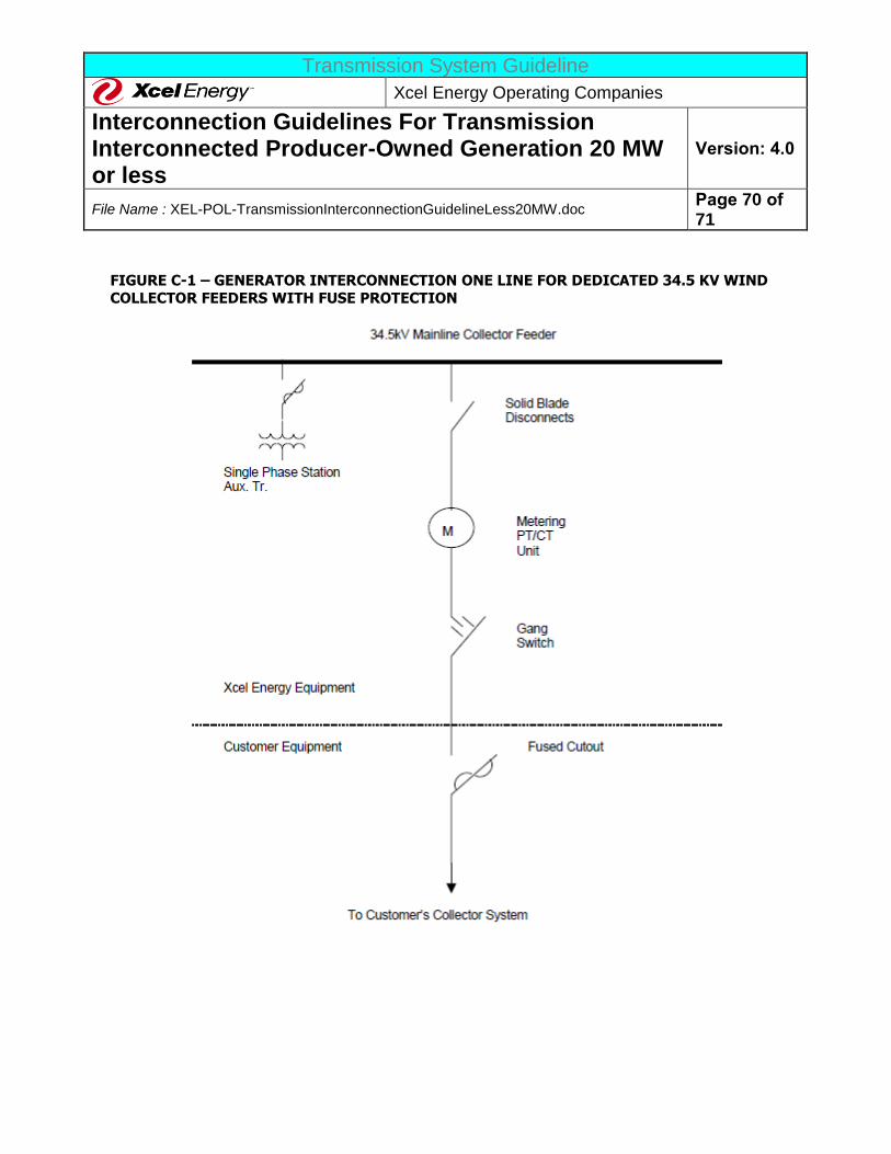
Transmission System Guideline
Xcel Energy Operating Companies
Interconnection Guidelines For Transmission Interconnected Producer-Owned Generation 20 MW or less
Version: 4.0
File Name : XEL-POL-TransmissionInterconnectionGuidelineLess20MW.doc Page 70 of 71
FIGURE C-1 – GENERATOR INTERCONNECTION ONE LINE FOR DEDICATED 34.5 KV WIND
COLLECTOR FEEDERS WITH FUSE PROTECTION
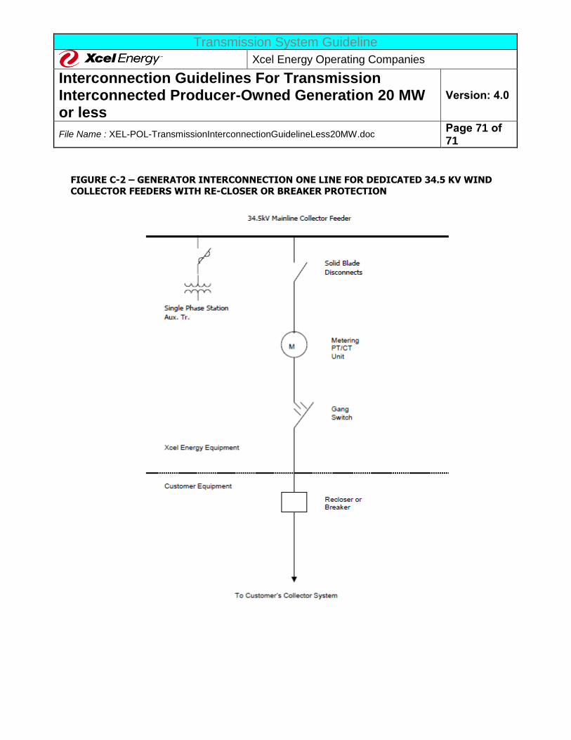
Transmission System Guideline
Xcel Energy Operating Companies
Interconnection Guidelines For Transmission Interconnected Producer-Owned Generation 20 MW or less
Version: 4.0
File Name : XEL-POL-TransmissionInterconnectionGuidelineLess20MW.doc Page 71 of 71
FIGURE C-2 – GENERATOR INTERCONNECTION ONE LINE FOR DEDICATED 34.5 KV WIND
COLLECTOR FEEDERS WITH RE-CLOSER OR BREAKER PROTECTION