x86 initial boot sequence - alessandro pellegrini
TRANSCRIPT
x86 Initial Boot Sequence
Advanced Operating Systems and VirtualizationAlessandro Pellegrini
A.Y. 2018/2019

The whole sequence at a glance
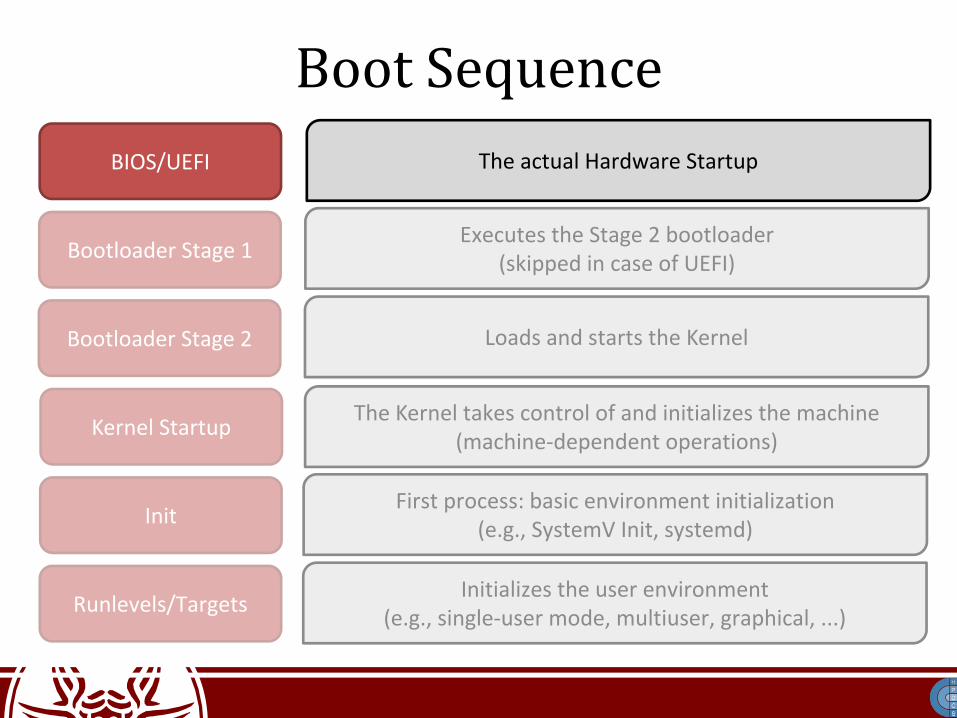
Boot SequenceBIOS/UEFI
Bootloader Stage 1
Bootloader Stage 2
Kernel Startup
Init
Runlevels/Targets
The actual Hardware Startup
Executes the Stage 2 bootloader(skipped in case of UEFI)
Loads and starts the Kernel
The Kernel takes control of and initializes the machine(machine-dependent operations)
First process: basic environment initialization(e.g., SystemV Init, systemd)
Initializes the user environment(e.g., single-user mode, multiuser, graphical, ...)

Hardware Power Sequences:The Pre-Pre-Boot
• When someone pushes the power button, the CPU can't simply jump up and start fetching code from flash memory
• The hardware waits for the power supply to settle to its nominal state
• Additional voltages must be supplied:– On x86 systems: 1.5, 3.3, 5, and 12 V– Power Sequencing: these must be provided in a
particular order

Hardware Power Sequences:The Pre-Pre-Boot
• The power is sequenced by controlling analog switches, typically field-effect transistors
• The sequence is often driven by a Complex Program Logic Device (CPLD)
• Platform clocks are derived from a small number of input clock and oscillator sources.– The devices use phase-locked loop circuitry to
generate the derived clocks used for the platform. – These clocks take time to converge.

Hardware Power Sequences:The Pre-Pre-Boot

Initial life of the System
• The power-sequencing CPLD can de-assert the reset line to the processor
• At this point, the system is in a very basic state:– Caches are disabled– The Memory Management Unit (MMU) is disabled– The CPU is executing in Real Mode (8086-
compatible)– Only one core can run actual code– Nothing is in RAM (what to execute?)

Segmented Memory
Segment A
Segment B
Segment C
logical address = <seg.id : offset> (e.g. <A : 0x10>)
Address space

Segmentation-based addressing
• There are 4 basic 16-bit segment registers:– CS: code segment– DS: data segment– SS: stack segment– ES: extra segment (to be used by the programmer)
• Intel 80386 (1985) added two new registers– FS and GS, with no predefined usage

Segmentation-based addressing
• The CPU resolves addresses as:
Assembly Instructions in Program
Logical Address
SegmentationUnit
x86 CPU with segmentation
Physical Address
Northbridge Chip
RAM Modules
Memory Address Translation

Segmentation Nowadays
• Segmentation is still present and always enabled
• Each instruction that touches memory implicitly uses a segment register:– a jump instruction uses CS– a push instruction uses SS
• Most segment registers can be loaded using a mov instruction
• CS can be loaded only with a jmp or a call

x86 Real Mode
• 16-bit instruction execution mode• 20-bit segmented memory address space
– 1 MB of total addressable memory• Address in segment registers is the 16-bits
higher part• Each segment can range from 1 byte to 65,536
bytes (16-bit offset)

Real Mode Addressing Resolution

Addressing in x86 Real Mode
GrowingPhysicalAddresses
0000:0000
FFFF:FFFF

Addressing in x86 Real Mode
GrowingPhysicalAddresses
0000:0000
FFFF:FFFF
Weren't they20 bits?

Addressing in x86 Real Mode
GrowingPhysicalAddresses
0000:0000
FFFF:FFFF
Weren't they20 bits?
Largest addressis FFFFF!

First Fetched Instruction
• The first fetched address is F000:FFF0– This is known as the reset vector– On IBM PCs this is mapped to a ROM: the BIOS– This gives space only to 16 bytes from the top of
ROM memory:ljmp $0xf000,$0xe05b
• This is where the BIOS code is loaded

BIOS Operations
• The BIOS first looks for video adapters that may need to load their own routines– These ROMs are mapped from C000:0000 to
C780:0000• Power-On Self-Test (POST)
– Depends on the actual BIOS– Often involves testing devices (keyboard, mouse)– Video Card Initialization– RAM consistency check

BIOS Operations
• Boot configuration loaded from CMOS (64 bytes)– For example, the boot order
• Shadow RAM initialization– The BIOS copies itself into RAM for faster access
• The BIOS tries to identify the Stage 1 bootloader, (512 bytes) using the specified boot order and loads it to memory at 0000:7c00
• Control is given with:ljmp $0x0000,$0x7c00

The RAM after the BIOS startup
Low Memory
VGA Display
16-bit devices,expansion ROM
BIOS ROM
0x00000000
0x000A0000 (640 Kb)
0x000C0000 (768 Kb)
0x000F0000 (960 Kb)
0x00100000 (1 Mb)
The only available"RAM" in the
early days
The bootloaderis loaded here

Boot SequenceBIOS/UEFI
Bootloader Stage 1
Bootloader Stage 2
Kernel Startup
Init
Runlevels/Targets
The actual Hardware Startup
Executes the Stage 2 bootloader(skipped in case of UEFI)
Loads and starts the Kernel
The Kernel takes control of and initializes the machine(machine-dependent operations)
First process: basic environment initialization(e.g., SystemV Init, systemd)
Initializes the user environment(e.g., single-user mode, multiuser, graphical, ...)
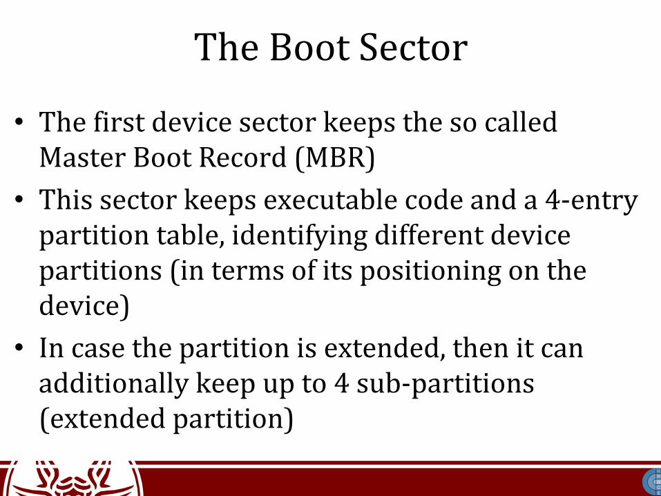
The Boot Sector
• The first device sector keeps the so called Master Boot Record (MBR)
• This sector keeps executable code and a 4-entry partition table, identifying different device partitions (in terms of its positioning on the device)
• In case the partition is extended, then it can additionally keep up to 4 sub-partitions (extended partition)

The Device Organization
Boot sector: it can contain additional boot code
Boot partition
Extended partition boot record
Partition table
Boot code
Partition 1 Partition 3 (extended)

The Master Boot Record (MBR)• This implements the Stage 1 bootloader• (Less than) 512 bytes can be used to load the
operating system

The Master Boot Record (MBR)
• The initial bytes of the MBR can contain the BIOS Parameter Block (BPB)
• It is a data structure describing the physical layout of a data storage volume– It is used, e.g., by FAT16, FAT32, and NTFS
• This eats up additional space, and must be placed at the beginning of the MBR!– How to execute the code?

The Master Boot Record (MBR).code16 .text.globl _start;
_start:jmp .stage1_start OEMLabel: .string "BOOT"BytesPerSector: .short 512SectorsPerCluster: .byte 1ReservedForBoot: .short 1NumberOfFats: .byte 2RootDirEntries: .short 224LogicalSectors: .short 2880MediumByte: .byte 0x0F0SectorsPerFat: .short 9SectorsPerTrack: .short 18
Sides: .short 2HiddenSectors: .int 0LargeSectors: .int 0DriveNo: .short 0Signature: .byte 41 #41 = floppyVolumeID: .int 0x00000000VolumeLabel: .string "myOS"FileSystem: .string "FAT12"
.stage1_start: cli # Disable interrupts xorw %ax,%ax # Segment zero movw %ax,%ds movw %ax,%es movw %ax,%ss ...

The Master Boot Record (MBR).code16 .text.globl _start;
_start:jmp .stage1_start OEMLabel: .string "BOOT"BytesPerSector: .short 512SectorsPerCluster: .byte 1ReservedForBoot: .short 1NumberOfFats: .byte 2RootDirEntries: .short 224LogicalSectors: .short 2880MediumByte: .byte 0x0F0SectorsPerFat: .short 9SectorsPerTrack: .short 18
Sides: .short 2HiddenSectors: .int 0LargeSectors: .int 0DriveNo: .short 0Signature: .byte 41 #41 = floppyVolumeID: .int 0x00000000VolumeLabel: .string "myOS"FileSystem: .string "FAT12"
.stage1_start: cli # Not safe here! xorw %ax,%ax # Segment zero movw %ax,%ds movw %ax,%es movw %ax,%ss ...
What about CS?

The Stage 1 Bootloader must...
• Enable address A20• Switch to 32-bit protected mode• Setup a stack• Load the kernel
– Yet, the kernel is on disk: how to navigate the file system? There is not much space for code...
– Load the Stage 2 bootloader!

A20 Enable
• Intel 80286 increased the addressable memory to 16 Mb (24 address lines)
• How to keep backward compatibility with 8086?– "wrap-around" problem– By default address line 20 is forced to zero!
• How to enable/disable this line?– Use the 8042 keyboard controller (sic!)– It had a spare pin which they decided to route the
A20 line through
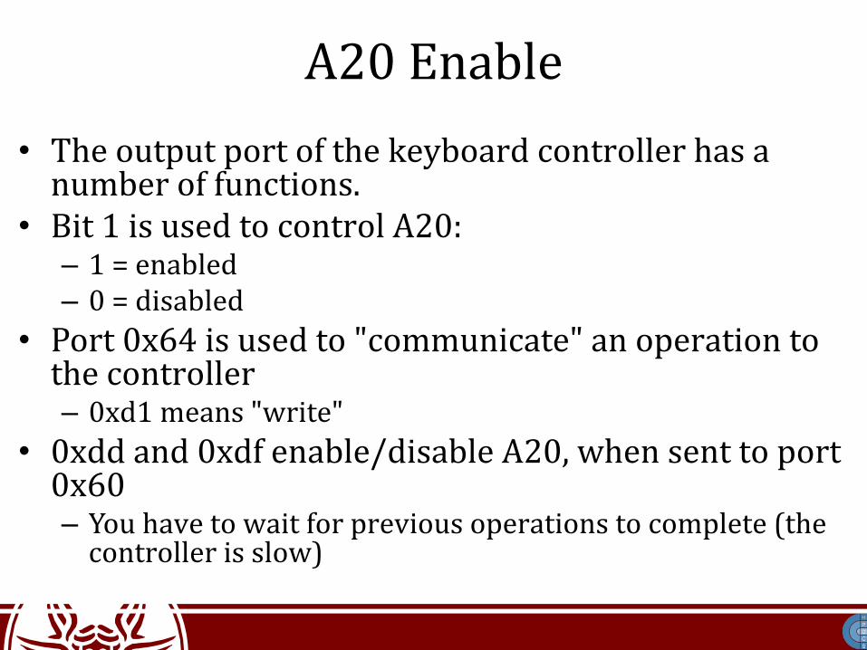
A20 Enable• The output port of the keyboard controller has a
number of functions.• Bit 1 is used to control A20:
– 1 = enabled– 0 = disabled
• Port 0x64 is used to "communicate" an operation to the controller– 0xd1 means "write"
• 0xdd and 0xdf enable/disable A20, when sent to port 0x60– You have to wait for previous operations to complete (the
controller is slow)

A20 Enable
call wait_for_8042 movb $0xd1, %al #command write outb %al, $0x64 call wait_for_8042 movb $0xdf, %al # Enable A20 outb %al, $0x60 call wait_for_8042 ...
wait_for_8042: inb %al, $0x64 tesb $2, %al # Bit 2 set = busy jnz wait_for_8042 ret

x86 Protected Mode
• This execution mode was introduced in 80286 (1982)
• With 80386 (1985) it was extended by adding paging
• CPUs start in Real Mode for backwards compatibility
• Still today, x86 Protected Mode must be activated during system startup

x86_64 Registers

x86_64 Registers

CR0

Entering Basic Protected Mode
• The code must set bit 0 (PE) of register CR0• Setting PE to 1 does not immediately activate all
its facilites• It happens when the CS register is first updated• This can be only done using a far jump (ljmp)
instruction, as already mentioned.• After this, code executes in 32/64-bit mode
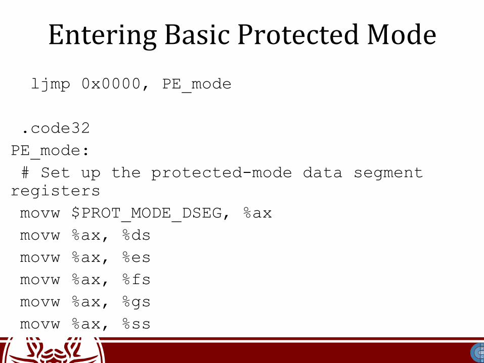
Entering Basic Protected Mode ljmp 0x0000, PE_mode
.code32PE_mode: # Set up the protected-mode data segment registers movw $PROT_MODE_DSEG, %ax movw %ax, %ds movw %ax, %es movw %ax, %fs movw %ax, %gs movw %ax, %ss

Segment Registers in Protected Mode
• In Protected Mode, a segment is no longer a raw number
• It contains (also) an index into a table of segment descriptors
• There are three types of segments:– code– data– system

Descriptor Table Entry
• Base: 32-bit linear addressing pointing to the beginning of the segment
• Limit: size of the segment• G: Granularity. If set, size is to be multiplied by 4096• Descriptor Privilege Level (DPL): a number in [0-3]
to control access to the segment

Protected Mode: Privilege Levels
Ring 3 has restricted access to memory management, instructions execution (around 15 allowed only at ring 0), and I/O ports

Descriptor Tables
• Two tables are available on x86 architectures• Global Descriptor Table (GDT):
– This is a system-wide table of descriptors– It is pointed by the GDTR register
• Local Descriptor Table (LDT):– Pointed by the LDTR register– Not used anymore

Segment Selectors
• TI: set to 0 for the GDT, set to 1 for the LDT• Index: specifies the segment selector within the
associated table• Requested Privilege Level (RPL): we'll come to
that later

Segmented Addressing Resolution

Segmented Addressing Resolution
Segmentation cannot be disabled

Segment Caching• Accessing the GDT for every memory access is
not performance-wise• Segment registers have a non-programmable
hidden part to store the cached descriptor
Segment Register
Selector Descriptor(non-programmable)
DescriptorTable
MemorySegment
Descriptor

x86 Enforcing Protection
• A Descriptor Entry has a DPL• The firmware must check if an access to a
certain segment is allowed• There must be a way to change current privilege
Change always allowed
Should be controlled/denied

Data Segment vs Code Segment
• RPL is present only in data segment selectors (e.g. SS or DS)
• Current Privilege Level (CPL): this is only in CS, which can be loaded only with a ljmp/lcall
• Overall we have 3 different privilege-level fields:CPL, RPL, and DPL

Protection upon Segment Load
• CPL is managed by the CPU: it's always equals to the current CPU privilege level
• CPU Memory protection comes at two points:– Memory access via a linear address– Data segment selector load operation

Protection upon Segment Load
For SS, the condition is:CPL = RPL = DPL

Getting Higher Privileges
• Accessing segment with a higher privilege (lower ring) with no control might allow malicious code to subvert the kernel
• To control transfer, code must pass through a controlled gate
• Gate descriptors are used to identify possible gates through which control can pass

Controlled Access Through Gates
User routine
Kernel routine B
Kernel routine A
Cross-segment jumpthrough a gate
Non-admittedcross-segment
jump
Kernel Space(Ring 0)
User Space(Ring 3)
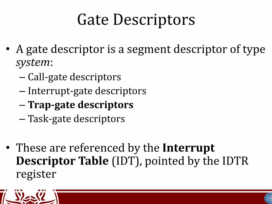
Gate Descriptors
• A gate descriptor is a segment descriptor of type system:– Call-gate descriptors– Interrupt-gate descriptors– Trap-gate descriptors– Task-gate descriptors
• These are referenced by the Interrupt Descriptor Table (IDT), pointed by the IDTR register

IDT and GDT Relations
GDTR
IDTR
System IDT
System GDT
offsetselector
segmentdescriptor
Kernel Text Segment
256entries
InterruptHandler

GDT in Linux
There is one copy of this table for each core
Shared across all coresDifferent for all cores

i386 Task State Segment (TSS)
• Its a structure keeping information about a task• It is intended to handle task management• It stores:
– Processor registers state– I/O Port Permissions– Inner-level Stack Pointers– Previous TSS link

i386 Task State Segment (TSS)
• It can be everywhere in memory (hence the GDT entry required to access it)
• On Linux, it's in kernel data memory• Each TSS is stored in the int_tss array.• The selector is kept in the Task Register (TR)• It can be loaded using the privileged ltr
instruction (CPL = 0)

i386 Task State Segment (TSS)Pointer to
a bitmap
CPU State
Privilege-level stacks

i386 Task State Segment (TSS)
• The Base field within the n-th core TSS register points to the n-th entry of the int_tss array
• G=0 and Limit=0xeb– given that TSS is 236 bytes in size
• DPL=0•TSS cannot be accessed in user mode

TSS on x64I/O Map Base Address
IST7 (high)IST7 (low)IST6 (high)IST6 (low)IST5 (high)IST5 (low)IST4 (high)IST4 (low)IST3 (high)IST3 (low)IST2 (high)IST2 (low)IST1 (high)IST1 (low)
RSP2 (high)RSP2 (low)RSP1 (high)RSP1 (low)RSP0 (high)RSP0 (low)
• Registers are gone.• The Interrupt Stack Table
(IST) identifies 7 stack pointers to handle interrupts
• Entries in the IDT are modified to allow picking one of these stacks
• Value 0 tells the firmware not to use the IST mechanism

Entering Ring 0 from Ring 3

Protected Mode Paging
• Since 80386, x86 CPUs add an additional step in address translation
Assembly Instructions in Program
Logical Address
SegmentationUnit
x86 CPU with segmentation and paging
Linear Address
Northbridge Chip
RAM Modules
Memory Address Translation
PagingUnit
PhysicalAddress
Protected Mode Paging
• Paging has to be explicitly enabled– Entering Protected Mode does not enable it
automatically– Several data structures must be setup before
• Paging allows to manage memory protection at a smaller granularity than segmentation

i386 Paging Scheme

i386 Paging Scheme
• Both levels are based on 4 KB memory blocks • Each block is an array of 4-byte entries• Hence we can map 1K x 1K pages• Since each page is 4 KB in size, we get a 4 GB
virtual addressing space

i386 PDE entries
(Sticky bit)

i386 PTE entries
(Sticky bit)
(TLB caching policy)
(Used for COW)

Virtual to Physical Translation
Assembly Instructions in Program
Logical Address
SegmentationUnit
x86 CPU with segmentation and paging
Linear Address
Northbridge Chip
RAM Modules
Memory Address Translation
PagingUnit
PhysicalAddress

Paging Unit Operations• Upon a TLB miss, firmware accesses the page table• The first checked bit is PRESENT• If this bit is zero, a page fault occurs which gives rise to a trap• CPU registers (including EIP and CS) are saved on the system
stack• They will be restored when returning from trap: the trapped
instruction is re-executed• Re-execution might give rise to additional traps, depending
on firmware checks on the page table• As an example, the attempt to access a read only page in write
mode will give rise to a trap (which triggers the segmentation fault handler)
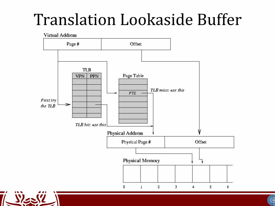
Translation Lookaside Buffer

Linux memory layout on i386
0xBFFFFFFF
...
0x00000000
0xFFFFFFFF
...
0xC0000000
User Space(3 GB)
Kernel(1 GB)

Physical Address Extension (PAE)
• An attempt to extend over the 4GB limit on i386 systems
• Present since the Intel Pentium Pro• Supported on Linux since kernel 2.6• Addressing is extended to 36 bits• This allows to drive up to 64 GB of RAM memory• Paging uses 3 levels• CR4.PAE-bit (bit 5) tells if PAE is enabled

Physical Address Extension (PAE)

x64 Paging Scheme
• PAE is extended via the so called “long addressing”• 264 bytes of logical memory in theory• Bits [49-64] are short-circuited
– Up to 248 canonical form addresses (lower and upper half)– A total of 256 TB addressable memory
• Linux currently allows for 128 TB of logical addressing of individual processes and 64 TB for physical addressing

Canonical Addresses
64-bit 48-bit

Linux memory layout on x64
0x0000 0000 0000 0000
0xFFFF FFFF FFFF FFFF
TEXT
DATA
Kernel
0xFFFF 8000 0000 0000
0x0000 7FFF FFFF FFFF
Non-canonicaladdressesStack
HeapShared Objects

48-bit Page Table (4KB pages)
Also referred to as Page General Directory (PGD)
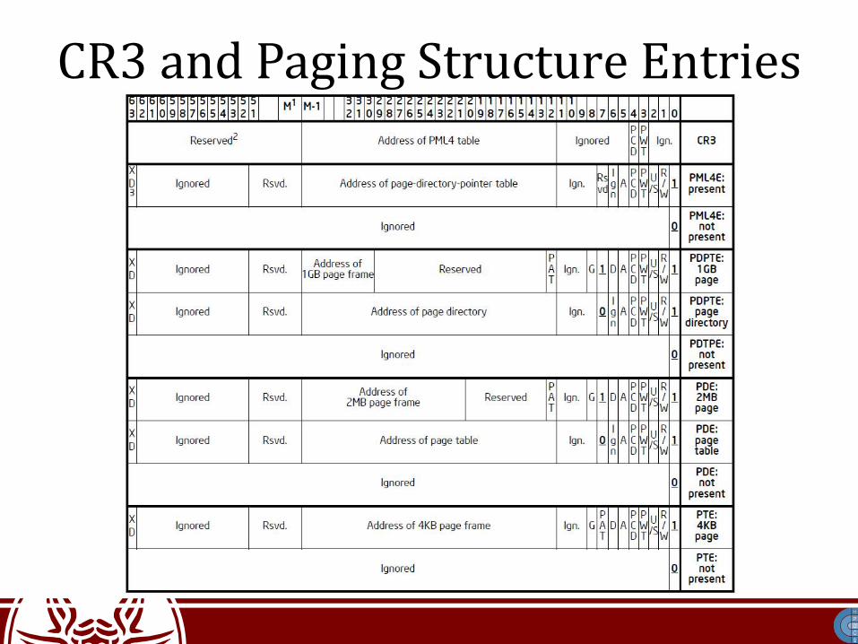
CR3 and Paging Structure Entries

Huge Pages
• Ideally x64 processors support them starting from PDPT
• Linux typically offers the support for huge pages pointed by the PDE (page size 512*4KB)
• See: /proc/meminfo and /proc/sys/vm/nr_hugepages• These can be mmap'ed via file descriptors and/or
mmap parameters (e.g. MAP_HUGETLB flag) • They can also be requested via the madvise(void *,
size_t, int) system call (with MADV_HUGEPAGE flag)

How to enable x64 longmode• The first step is (of course) to setup a coherent page table• We must then tell the CPU to enable Long Mode• Refer to arch/x86/include/uapi/asm/msr-index.h
for the definition of the symbolsmovl $MSR_EFER, %ecxrdmsrbtsl $_EFER_LME, %eaxwrmsrpushl $__KERNEL_CSleal startup_64(%ebp), %eaxpushl %eaxmovl $(X86_CR0_PG | X86_CR0_PE), %eaxmovl %eax, %cr0lret

Boot SequenceBIOS/UEFI
Bootloader Stage 1
Bootloader Stage 2
Kernel Startup
Init
Runlevels/Targets
The actual Hardware Startup
Executes the Stage 2 bootloader(skipped in case of UEFI)
Loads and starts the Kernel
The Kernel takes control of and initializes the machine(machine-dependent operations)
First process: basic environment initialization(e.g., SystemV Init, systemd)
Initializes the user environment(e.g., single-user mode, multiuser, graphical, ...)

Second Stage Bootloader• There are various versions of this software
– In GRUB it is GRUB Stage 2– In Win NT it is c:\ntldr
• The second stage bootloader reads a configuration file, e.g. to startup a boot selection menu– grub.conf in GRUB, boot.ini in Win NT
• The kernel initial image is loaded in memory using BIOS disk I/O services– For Linux, it is /boot/vmlinuz-*– For Win NT, it is c:\Windows\System32\ntoskrnl.exe
Historical Linux Bootcode
• The historical bootsector code for LINUX (i386) is in arch/i386/bootsect.S (no longer used)
• It loaded arch/i386/bootsetup.S and the kernel image in memory
• The code in arch/i386/bootsetup.S initialized the architecture (e.g. the CPU state for the actual kernel boot)
• It ultimately gave control to the initial kernel image

Unified Extensible Firmware Interface (UEFI)
• Modular (you can extend it with drivers)• Runs on various platforms• It's written in C• It supports a bytecode (portability to other
architectures)
• It's completely different from BIOS

UEFI Boot• UEFI boot manager takes control right after the
system is powered on• It looks at the boot configuration• It loads the firmware settings into RAM from
nvRAM• Startup files are stored on a dedicated EFI System
Partition (ESP)– It's a FAT32 partition– It has one folder for each OS on the system
• MBR cannot handle disks larger than 2TB

UEFI Boot
• It can automatically detect new uefi-boot targets– UEFI uses standard path names
• /efi/boot/boot_x64.efi
• /efi/boot/bootaa64.efi
• UEFI programs can be easily written#include <efi.h>#include <efilib.h>
EFI_STATUS EFIAPIefi_main(EFI_HANDLE ImageHandle, EFI_SYSTEM_TABLE *SystemTable) {
InitializeLib(ImageHandle, SystemTable);Print(L"Hello World\n");
return EFI_SUCCESS;}
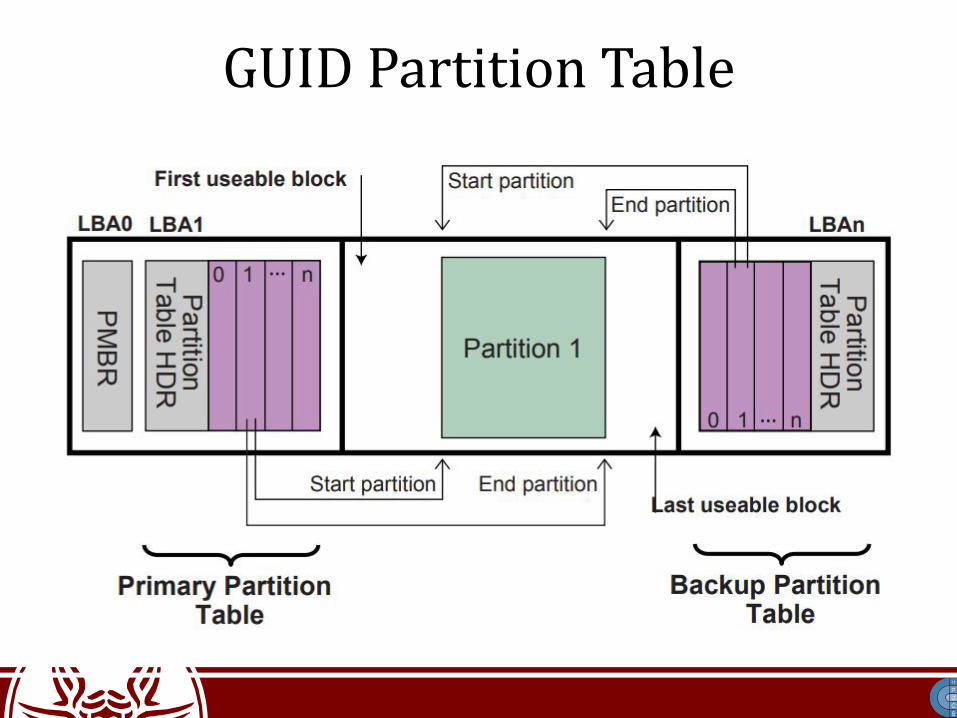
GUID Partition Table

Secure Boot
• There is a kind of malware which takes control of the system before the OS starts– MBR RootKits
• Usually, these RootKits hijack the IDT for I/O operations, to execute their own wrapper
• When the kernel is being loaded, the RootKit notices that and patches the binary code while loading it into RAM

Secure Boot
• UEFI allows to load only signed executables• Keys to verify signatures are installed in UEFI
configuration– Platform Keys (PK): tells who “owns and controls”
the hardware platform– Key-Exchange Keys (KEK): shows who is allowed to
update the hardware platform– Signature Database Keys (DB): show who is allowed
to boot the platform in secure mode

Dealing with multicores
• Who shall execute the startup code?• For legacy reasons, the code is purely sequential• Only one CPU core (the master) should run the
code
• At startup, only one core is active, the others are in an idle state
• The startup procedure has to wake up other cores during kernel startup

Interrupts on Multicore Architectures
• The Advanced Programmable Interrupt Controller (APIC) is used for sophisticated interrupt sending/redirection
• Each core has a Local APIC (LAPIC) controller, which can send Inter-Processor Interrupts (IPIs)– LAPICs are connected through the (logical) “APIC Bus”– LINT 0 : normal interrupts — LINT 1 : Non-maskable
Interrupts• I/O APICs contain a redirection table, which is used to
route the interrupts it receives from peripheral buses to one or more local APICs

LAPIC

Interrupt Control Register• The ICR register is used to initiate an IPI• Values written into it specify the type of
interrupt to be sent, and the target core

Broadcast INIT-SIPI-SIPI Sequence# address Local-APIC via register FS
mov $sel_fs, %ax
mov %ax, %fs
# broadcast 'INIT' IPI to 'all-except-self'
mov $0x000C4500, %eax ; 11 00 0 1 0 0 0 101 00000000
mov %eax, %fs:(0xFEE00300)
.B0: btl $12, %fs:(0xFEE00300)
jc .B0
# broadcast 'Startup' IPI to 'all-except-self'
# using vector 0x11 to specify entry-point
# at real memory-address 0x00011000
mov $0x000C4611, %eax ; 11 00 0 0 1 0 0 0 110 00010001
mov %eax, %fs:(0xFEE00300)
.B1: btl $12, %fs:(0xFEE00300)
jc .B1