x-ray film processor 230 (vac)
TRANSCRIPT

XX--RRAAYY FFIILLMM PPRROOCCEESSSSOORR
22 33 00 (( VV AA CC ))
DDEEDDIICCAATTEEDD TTOO QQUUAALLIITTYY
A6732 ISO 13485:1996ISO 9001:2000
Air Techniques Inc.Hicksville, NY
PN 47104 Rev. F
Made by Air Techniques, Inc.for
ABOUT THE 100 PLUS TM . . . . . . . . . . . . . . . . . . . . . . . . . . . . . . . . . . . . . . . . . . . . . . . . . . . .2On-Line Warranty Registration . . . . . . . . . . . . . . . . . . . . . . . . . . . . . . . . . . . . . . . . . . . . . . . . .3Warranty . . . . . . . . . . . . . . . . . . . . . . . . . . . . . . . . . . . . . . . . . . . . . . . . . . . . . . . . . . . . . . . . . . .3Corporate Headquarters . . . . . . . . . . . . . . . . . . . . . . . . . . . . . . . . . . . . . . . . . . . . . . . . . . . . . .3Safety Warnings . . . . . . . . . . . . . . . . . . . . . . . . . . . . . . . . . . . . . . . . . . . . . . . . . . . . . . . . . . . . .3
PREINSTALLATION
KEY PARTS IDENTIFICATION (EXTERNAL) . . . . . . . . . . . . . . . . . . . . . . . . . . . . . . . . . . . . . .4KEY PARTS IDENTIFICATION (INTERNAL) . . . . . . . . . . . . . . . . . . . . . . . . . . . . . . . . . . . . . .5SPECIFICATIONS . . . . . . . . . . . . . . . . . . . . . . . . . . . . . . . . . . . . . . . . . . . . . . . . . . . . . . . . . . .6SITE REQUIREMENTS . . . . . . . . . . . . . . . . . . . . . . . . . . . . . . . . . . . . . . . . . . . . . . . . . . . . . . .7STANDPIPE INSTALLATION . . . . . . . . . . . . . . . . . . . . . . . . . . . . . . . . . . . . . . . . . . . . . . . . . . .8RECOVERY CONTAINERS AND STANDPIPE INSTALLATION . . . . . . . . . . . . . . . . . . . . . . . .9TOOLS REQUIRED . . . . . . . . . . . . . . . . . . . . . . . . . . . . . . . . . . . . . . . . . . . . . . . . . . . . . . . . .10UNPACK THE 100 PLUS . . . . . . . . . . . . . . . . . . . . . . . . . . . . . . . . . . . . . . . . . . . . . . . . . . . .10MOUNT PROCESSOR . . . . . . . . . . . . . . . . . . . . . . . . . . . . . . . . . . . . . . . . . . . . . . . . . . . . . .10TEST WITH WATER FOR SEAL INTEGRITY . . . . . . . . . . . . . . . . . . . . . . . . . . . . . . . . . . . . .11INSTALL DRYER TRANSPORT . . . . . . . . . . . . . . . . . . . . . . . . . . . . . . . . . . . . . . . . . . . . . . .11FILL WITH CHEMISTRY . . . . . . . . . . . . . . . . . . . . . . . . . . . . . . . . . . . . . . . . . . . . . . . . . . . . .12INSTALL DEVELOPER, FIXER, WASH TRANSPORTS . . . . . . . . . . . . . . . . . . . . . . . . . . . . .12SET DEVELOPER TEMPERATURE . . . . . . . . . . . . . . . . . . . . . . . . . . . . . . . . . . . . . . . . . . . .13SET DRYER POWER . . . . . . . . . . . . . . . . . . . . . . . . . . . . . . . . . . . . . . . . . . . . . . . . . . . . . . .13CALIBRATE REPLENISHMENT PUMPS . . . . . . . . . . . . . . . . . . . . . . . . . . . . . . . . . . . . . . . .14SET “FLOOD” REPLENISHMENT . . . . . . . . . . . . . . . . . . . . . . . . . . . . . . . . . . . . . . . . . . . . . .15CHECK DRIVE BELT TENSION . . . . . . . . . . . . . . . . . . . . . . . . . . . . . . . . . . . . . . . . . . . . . . .16FINAL ASSEMBLY . . . . . . . . . . . . . . . . . . . . . . . . . . . . . . . . . . . . . . . . . . . . . . . . . . . . . . . . . .17
OPERATION
OPERATOR CONTROLS . . . . . . . . . . . . . . . . . . . . . . . . . . . . . . . . . . . . . . . . . . . . . . . . . . . .18STATUS LIGHTS . . . . . . . . . . . . . . . . . . . . . . . . . . . . . . . . . . . . . . . . . . . . . . . . . . . . . . . . . . .19DAILY OPERATION . . . . . . . . . . . . . . . . . . . . . . . . . . . . . . . . . . . . . . . . . . . . . . . . . . . . . . . . .20
Table 1: Film Series Processing Time
SERVICE
MAINTENANCEDaily, Monthly, Quarterly . . . . . . . . . . . . . . . . . . . . . . . . . . . . . . . . . . . . . . . . . . . . . . . . . . . . .21STATUS/ SERVICE DIAGNOSTIC LIGHTS . . . . . . . . . . . . . . . . . . . . . . . . . . . . . . . . . . . .22-26
TROUBLE SHOOTINGTable of Contents . . . . . . . . . . . . . . . . . . . . . . . . . . . . . . . . . . . . . . . . . . . . . . . . . . . . . . . . . . .27Equipment, Film, Electrical Problems . . . . . . . . . . . . . . . . . . . . . . . . . . . . . . . . . . . . . . . . .28-38Table 2: Voltage and Resistance Values . . . . . . . . . . . . . . . . . . . . . . . . . . . . . . . . . . . . . . . . .39Table 3: Thermistor Temperature/ Resistance Values . . . . . . . . . . . . . . . . . . . . . . . . . . . . . . .40
PARTS / ASSEMBLIES:Table of Contents . . . . . . . . . . . . . . . . . . . . . . . . . . . . . . . . . . . . . . . . . . . . . . . . . . . . . . . . . . .41Exterior, Interior, Transports (Listings and Illustrations) . . . . . . . . . . . . . . . . . . . . . . . . . . .42-57
ADDENDA
WIRING SCHEMATIC . . . . . . . . . . . . . . . . . . . . . . . . . . . . . . . . . . . . . . . . . . . . . . . . . . . . . . .58PLUMBING SCHEMATIC . . . . . . . . . . . . . . . . . . . . . . . . . . . . . . . . . . . . . . . . . . . . . . . . . . . .59
TTAABBLLEE OOFF CCOONNTTEENNTTSS
1

EXCELLENCE IN PROCESSOR PERFORMANCEYour 100 PLUS X-ray Film Processor is designed and manufactured in the U.S.A by All-Pro Imaging.
Every processor bearing the All-Pro name meets our high standards for manufacturing and
performance excellence. From design through production you are assured of quality images for every
patient, every time.
OVERVIEWDiagnostic films are delivered quickly with a 26 second feed time and a dry-to-drop processing time of
120 seconds for a 17” long film. Minimum film length is 4 inches; maximum film width is 14 inches.
Both single-sided and two-sided emulsion film can be processed. (See Table 1, Film Series Processing
Time, p.20)
Attention to design detail enhances the performance of the 100 PLUS. Film is fed into the front of the
100 PLUS and conveniently returned on top of the cover. The 100 PLUS alerts the operator to feed in
another film with a READY LIGHT and audible tone. The light-tight covered feed tray, a time saving
feature, eliminates waiting until the last film is completely inside the 100 PLUS before the operator can
leave the darkroom.
With its microprocessor, the 100 PLUS automatically monitors and controls developer temperature and
dryer power as well as developer, fixer and wash water levels. The STATUS LIGHTS, located behind
the name plate on the front panel, display the status of every controlled function.
To initiate processing, just insert a film into the film inlet. The 100 PLUS automatically switches from
standby to processing and automatically returns to standby when the last film is delivered. If no films
have been processed for 10 minutes, the anticrystallization cycle automatically activates and turns the
transport rollers for 10 seconds to rewet them. This helps prevent artifacts from appearing on the
processed film. The anticrystallization cycle may be continued overnight by putting the DAY/NIGHT
SWITCH into the Night position.
Chemistry replenishment is automatic and proportional to film length. For low volume users, “flood”
replenishment can be selected to extend chemistry life by additional replenishment during the
anticrystallization cycle.
Installation is simplified with separate developer, fixer and water drain hoses that can be routed
through either the front or rear of the 100 PLUS. Cold water is supplied through the water solenoid at
the rear of the processor. No special electrical wiring is required since the 100 PLUS operates from a
standard 230VAC 10A 50/60 Hz circuit.
The 100 PLUS is designed to make all components readily accessible for servicing. The
microprocessor control board, with its Diagnostic Service Lights, is conveniently located on the inside
of the swing-down front panel behind a protective enclosure. Mounted on the chassis and easy to reach
are the drive motor and replenishment pumps, in the front, and the single motor, dual head recirculation
pumps, which fully purge when the tanks are drained, on the side.
By following a regular maintenance and service schedule, the 100 PLUS will provide years of
dependable, reliable service. Congratulations. You made the right choice!
AABBOOUUTT TTHHEE 110000 PPLLUUSS TTMM
2

ALL-PRO IMAGING 1 YEAR LIMITED WARRANTY
Your 100 PlusTM Automatic Film Processor is warranted to be free from defects in material and
workmanship from the date of installation for a period of 1 year.
Any item returned freight prepaid to our factory in Hicksville, New York, through an authorized
dealer, will be repaired or replaced at our option at no charge provided that our inspection shall
indicate it to have been defective. Dealer labor, shipping and handling costs are not covered by
this warranty.
This warranty does not apply to damage due to shipping, misuse, careless handling or repairs by
other than authorized service personnel. All-Pro Imaging is not liable for indirect or consequential
damage or loss of any nature in connection with this equipment.
This warranty is in lieu of all other warranties expressed or implied. No representative or person
is authorized to assume any other liability for us in connection with the sale of our equipment.
WWAARRRRAANNTTYY
3
Warns the user that uninsulated voltage within
the unit may be of sufficient magnitude to
cause electric shock.
Alerts the user that important Operating and
Maintenance instructions have been included with
the unit. Read carefully to avoid any problems.
Indicates type B equip-
ment in accordance with
IEC 601-1
WARNING: To prevent fire or electrical shock, do not expose this appliance to rain or moisture.
ATTENTION USERS:
SSAAFFEETTYY WWAARRNNIINNGGSS
Quickly and easily register your new 100 PlusTM Automatic Film Processor on-line. Just haveyour product model and serial numbers available. Then go to the ALLPRO Imaging website,www.allproimaging.com, click the warranty link and complete the registration form. Thison-line registration ensures a record for the warranty period and helps ALLPRO Imaging keepyou informed of product updates and other valuable information.
70 Cantiague Rock Road, P. O. Box 870, Hicksville, New York 11802-0870
1-800-AIR-TECH (1-800-247-8324) (516) 433-7676 FAX: (516) 433-7684
www.allproimaging.com© Copyright ALLPRO Imaging
100 PLUS TM is a trademark of ALLPROTM
ALLPRO© is a registered trademark of ALLPROTM
OONN--LLIINNEE WWAARRRRAANNTTYY RREEGGIISSTTRRAATTIIOONN
CCOORRPPOORRAATTEE HHEEAADDQQUUAARRTTEERRSS

PPRREEIINNSSTTAALLLLAATTIIOONN
KKeeyy PPaarrttss IIddeennttiiffiiccaattiioonn [[EExxtteerrnnaall]]
4

PPRREEIINNSSTTAALLLLAATTIIOONN
KKeeyy PPaarrttss IIddeennttiiffiiccaattiioonn [[IInntteerrnnaall]]
5
6
PPRREEIINNSSTTAALLLLAATTIIOONN
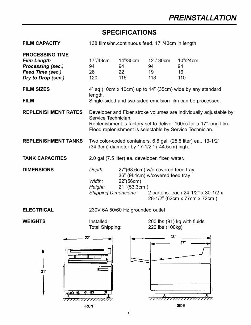
SPECIFICATIONS
FILM CAPACITY 138 films/hr..continuous feed. 17’’/43cm in length.
PROCESSING TIMEFilm Length 17”/43cm 14”/35cm 12”/ 30cm 10”/24cmProcessing (sec.) 94 94 94 94Feed Time (sec.) 26 22 19 16Dry to Drop (sec.) 120 116 113 110
FILM SIZES 4” sq (10cm x 10cm) up to 14” (35cm) wide by any standardlength.
FILM Single-sided and two-sided emulsion film can be processed.
REPLENISHMENT RATES Developer and Fixer stroke volumes are individually adjustable by Service Technician.Replenishment is factory set to deliver 100cc for a 17” long film.Flood replenishment is selectable by Service Technician.
REPLENISHMENT TANKS Two color-coded containers. 6.8 gal. (25.8 liter) ea., 13-1/2”(34.3cm) diameter by 17-1/2 “ ( 44.5cm) high.
TANK CAPACITIES 2.0 gal (7.5 liter) ea. developer, fixer, water.
DIMENSIONS Depth: 27”(68.6cm) w/o covered feed tray36” (9I.4cm) w/covered feed tray
Width: 22”(56cm)Height: 21 “(53.3cm )Shipping Dimensions: 2 cartons. each 24-1/2’’ x 30-1/2 x
28-1/2” (62cm x 77cm x 72cm )
ELECTRICAL 230V 6A 50/60 Hz grounded outlet
WEIGHTS Installed: 200 lbs (91) kg with fluidsTotal Shipping: 220 lbs (100kg)

7
PPRREEIINNSSTTAALLLLAATTIIOONN
SSIITTEE RREEQQUUIIRREEMMEENNTTSS
CLEARANCES O SIDES: 24" ( 61cm) recommended
O REAR: 3" (8cm) recommended
O FRONT: (Incl. film feed tray): 30"(76cm) recommended
O TOP COVER: 18" (46cm) recommended
COUNTER HEIGHT 24" (61cm) - 32" (82cm) recommended
WEIGHT 200 lbs (91 kg) with fluids
ELECTRICAL O 230V /10 A 50/60 Hz grounded outletPlug may need to be changed to meet local requirements
O Processor equipped with a 6' (1.8m) long power cord
WASH WATER O Connection: 6’ water supply hose (provided)
O Temperature: 50° to 90° F (10° - 32° C)
O Pressure: 40 to 100 psi (3 - 7 bar)
O Flow rate: .5 gal/min (1.9 liter/min)
O Valve: Dedicated on/off hose cock with 3/4" male garden hose fitting.
O Water filtration may be required depending on area water conditions
O If the water supply temperature exceeds 90° F (30°C), a water chillermay be required
VACUUM BREAKER Built-in 1" (2.5cm) air break prevents back syphoning.
DRAIN O CAPACITY: 3 gal/min (11.4 liter/min)
O MATERIAL: Must be corrosion-resistant material i.e. PVC, cast iron. Do not use copper, brass or aluminum.
O LOCATION: 4" ( 10cm) minimum distance below bottomof processor
O CONNECTION: Floor drain or open standpipe
O Equipped with three color-coded drain hoses 8' (2.4m) long,3/4" (1.9cm) ID, which must slope smoothly down from
processor to drain without any "kinks", "U's" or upward bends. Route
drain hoses through front or rear of processor
VENTILATION O Ambient Room Temp: 59° - 86° F (15° - 30°C)Relative Humidity: 15% to 76%
O Heat loads: Standby: 250 BTU/hr (75 W)Moderate use: 1700 BTU/hr (500 W)
O Recommended ventilation rate: 10 air changes/hr
SAFELIGHT Follow film manufacturer's recommendations for type and size
of safelight. Position safelight so that film feed tray area is
illuminated and is not shadowed by the operator.
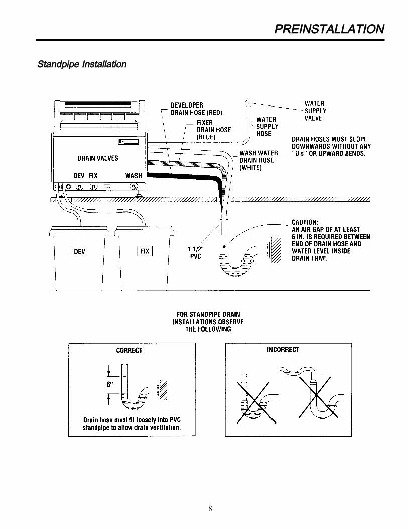
PPRREEIINNSSTTAALLLLAATTIIOONN
SSttaannddppiippee IInnssttaallllaattiioonn
8

PPRREEIINNSSTTAALLLLAATTIIOONN
RReeccoovveerryy CCoonnttaaiinneerrss aanndd SSttaannddppiippee IInnssttaallllaattiioonn
9
IINNSSTTAALLLLAATTIIOONN
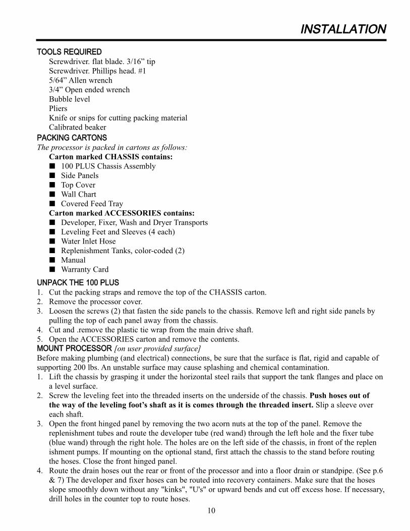
TTOOOOLLSS RREEQQUUIIRREEDD
Screwdriver. flat blade. 3/16” tip
Screwdriver. Phillips head. #1
5/64” Allen wrench
3/4” Open ended wrench
Bubble level
Pliers
Knife or snips for cutting packing material
Calibrated beaker
PPAACCKKIINNGG CCAARRTTOONNSS
The processor is packed in cartons as follows:Carton marked CHASSIS contains:
O 100 PLUS Chassis Assembly
O Side Panels
O Top Cover
O Wall Chart
O Covered Feed Tray
Carton marked ACCESSORIES contains:
O Developer, Fixer, Wash and Dryer Transports
O Leveling Feet and Sleeves (4 each)
O Water Inlet Hose
O Replenishment Tanks, color-coded (2)
O Manual
O Warranty Card
UUNNPPAACCKK TTHHEE 110000 PPLLUUSS
1. Cut the packing straps and remove the top of the CHASSIS carton.
2. Remove the processor cover.
3. Loosen the screws (2) that fasten the side panels to the chassis. Remove left and right side panels by
pulling the top of each panel away from the chassis.
4. Cut and .remove the plastic tie wrap from the main drive shaft.
5. Open the ACCESSORIES carton and remove the contents.
MMOOUUNNTT PPRROOCCEESSSSOORR [on user provided surface]Before making plumbing (and electrical) connections, be sure that the surface is flat, rigid and capable of
supporting 200 lbs. An unstable surface may cause splashing and chemical contamination.
1. Lift the chassis by grasping it under the horizontal steel rails that support the tank flanges and place on
a level surface.
2. Screw the leveling feet into the threaded inserts on the underside of the chassis. Push hoses out of
the way of the leveling foot’s shaft as it is comes through the threaded insert. Slip a sleeve over
each shaft.
3. Open the front hinged panel by removing the two acorn nuts at the top of the panel. Remove the
replenishment tubes and route the developer tube (red wand) through the left hole and the fixer tube
(blue wand) through the right hole. The holes are on the left side of the chassis, in front of the replen
ishment pumps. If mounting on the optional stand, first attach the chassis to the stand before routing
the hoses. Close the front hinged panel.
4. Route the drain hoses out the rear or front of the processor and into a floor drain or standpipe. (See p.6
& 7) The developer and fixer hoses can be routed into recovery containers. Make sure that the hoses
slope smoothly down without any "kinks", "U's" or upward bends and cut off excess hose. If necessary,
drill holes in the counter top to route hoses.
10

5. Level the processor front to back and side to side by adjusting the leveling feet. Check with bubble
level.
6. Screw the elbow end of the garden hose onto the solenoid valve located on the back of the processor
and connect the straight end to the water supply valve.
TEST WITH WATER FOR SEAL INTEGRITYAll-fittings are factory tested. Follow this procedure
to make sure no connections have loosened:
1. Fill the tanks with water.
2. Drain the tanks one at time by opening the drain valves located
at the front bottom of the processor. (See Figure 1) As each tank
drains, check all seals and connections. Close the valves after
completely draining each tank.
3. Put on the left and right side panels (not interchangeable).
Snap into place and fasten closed with screws.
4. Position the processor and recheck to make sure the processor
is level.
Note: The wash water drain valve in the closed position allowsa slow flow of water from the wash tank. The wash tank drainscompletely overnight to retard the growth of algae.
INSTALL DRYER TRANSPORT1. Examine the dryer transport. Be sure that all snap
rings, gears, tensioning bands and dryer air tubes
are in place. Turn the main drive gear to check for
free movement.
Caution: Before installing the transport: check the
chassis assembly to be sure that the tie wrap has
been removed from the main drive shaft. Also
check that the front-most saddle bearing has been
lubricated with white lithium grease or equivalent.
2. Install the dryer transport by lowering it into
the opening behind the wash tank. Place securely
onto the bracket in front of the transport .
(the back of the wash tank wall) and onto the
support behind the transport (on the chassis).
(See Figure 2) When installed, the main drive
gear is engaged with the rearmost worm on the
drive shaft. Be careful not to dislodge the dryer
air tubes from the dryer side panels.
3. Plug the electrical connector from the dryer transport into the
IINNSSTTAALLLLAATTIIOONN
Figure 1
Figure 2
11

receptacle mounted on the upper right rear chassis of the
100 PLUS. (See Figure 3)
FILL WITH CHEMISTRYCaution: Only use working strength Developer andFixer for automatic processing. Make sure drainvalves are closed.1. Fill the fixer tank with fixer to 1” below the top
of the tank (approximately 2.0 gal). Always fill
the fixer tank first to reduce the chance of
contamination. If fixer accidentally splashes into
the developer tank, clean up before continuing.
2. Fill the developer tank with developer to 1" below
the top of the tank (approximately 2.0 gal).
3. Fill the replenishment containers with developer and
fixer. Place the floating cover inside the developer container.
Place the covers on the containers and install the color-coded
replenishment wands in each container through the hole in the
top. Be sure that the wand goes through the slot in the floating
cover in the developer.
4. Put the replenishment containers in place. Push the replenishment wands to the bottom of the
containers. Make sure there are no kinks in the tubing.
INSTALL DEVELOPER, FIXER, WASH TRANSPORTS1. Check the developer, fixer and wash transports. Be sure that all snap rings, gears and tensioning bands
are in place. Also check each transport for squareness. If necessary, adjust by placing the transport on a
flat surface and loosen the screws on the cross ties. When the transport is square, retighten the screws.
Turn each main drive gear to check for free movement.
NOTE: Transports are color-coded: developer transport has a red sleeve; fixer transport a blue sleeve;wash transport has no sleeve.
2. Slowly lower each transport into its tank. Avoid splashing. Install the developer transport in the front
tank, the fixer transport in the middle tank and the wash transport in the rear tank. A thrust bearing on
the left side of the rack drive shaft positions the transport from left to right in the tank. When installed,
the main drive gear on each transport engages the main drive shaft worm.
IINNSSTTAALLLLAATTIIOONN
12
Figure 3

WARNING!
Procedures in this section must be performed only by qualified service technicians.Safety interlocks will be bypassed and hazardous voltages will be present.
To perform many of the procedures detailed below, it is necessary to “defeat” the interlock switch.
This is accomplished by inserting the blade of a screwdriver into the interlock switch opening.
Point the blade toward the rear of the processor when inserting.
SET DEVELOPER TEMPERATUREThe developer temperature is factory set at 92.5°F (33.6°C). If it is necessary to change this setting to
be in accordance with film manufacturer's temperature requirements, do the following:
1. Open the front hinged panel by removing the two acorn nuts at the top of the panel.
2. Open the protective cover by loosening the screws in the corners. Reset the potentiometer.
Verify actual temperatures by following the procedure below.
3. Plug in the power cord, open the water supply valve, turn on the main circuit breaker, and put
the Day/Night Switch into the Day position. Wait 15 - 20 minutes. The READY LIGHT will
illuminate and an audible tone sound. Wait 5 minutes.
4. Press the film sensor to activate the process cycle. Use a thermometer accurate to within ± l/4°F.
Check the developer temperature by placing the thermometer in the middle of the developer
transport and holding until the reading on the thermometer stabilizes. .
5. If the actual temperature is not the desired temperature, adjust the potentiometer accordingly and
check the temperature again. Close the protective cover and tighten the screws.
NOTE: The developer tank must be full and STATUS LIGHT #4 (DEV LEVEL) must be “on”. If this condition is not met, the heater will not operate.
SET DRYER POWERThe dryer potentiometer is factory set at position 3. (See Figure 5, p. 15) If it is necessary to change the
setting, do the following:
1. Open the protective cover by loosening the screws in the corners.
2. Set the potentiometer down to lower the power, set the potentiometer up to increase the power.
Always set to lowest setting that delivers consistently dry film. Close the protective cover and
tighten the screws.
IINNSSTTAALLLLAATTIIOONN
13

CALIBRATE
REPLENISHMENT PUMPSThe replenishment pumps on the 100 PLUS
are set to pump 100cc of chemistry in 26
seconds. Check film manufacturer's guide-
lines for recommended replenishment rates.
To check, and, if necessary, adjust these
rates, follow the procedure detailed below:
1. Prime the replenishment pumps by
pressing the film sensor. Hold down
until the flow from the replenishment
“J” tubes (on the left side of the tanks)
is steady, indicating that all lines and
pumps are properly filled. The replenish-
ment pumps will operate for a maximum
of 4 minutes as long as the film sensor is
depressed. If the film sensor is depressed
for more than 4 minutes, the replenishment
pumps lock out. (See p. 18)
2. Check developer replenishment rate:
O Raise and turn the developer “J” tube out of its socket and position it over a graduated beaker.
O Hold down the film sensor for 26 seconds and collect the pumped chemistry. Note the amountcollected.
3. To change the developer replenishment rate: (See Figure 4)
O Expose the phillips head screw on the flywheel by rotating the pump flywheel clockwise with the tip of a screwdriver or by repeatedly depressing the film sensor.
O Slightly loosen the screw and rotate the outermost plate of the flywheel to set the desired stroke volume.
O To deliver less chemistry, rotate the flywheel counterclockwise. To deliver more chemistryrotate the flywheel clockwise. Tighten the screw to lock in the replenishment rate.
O Hold down the film sensor for 26 seconds and collect the pumped chemistry. Note theamount collected.
O If correct, replace the "J" tube in its socket.
O If not correct, repeat the above procedure.4. Perform steps 2 and 3 for the fixer replenishment pump.
IINNSSTTAALLLLAATTIIOONN
14
Figure 4
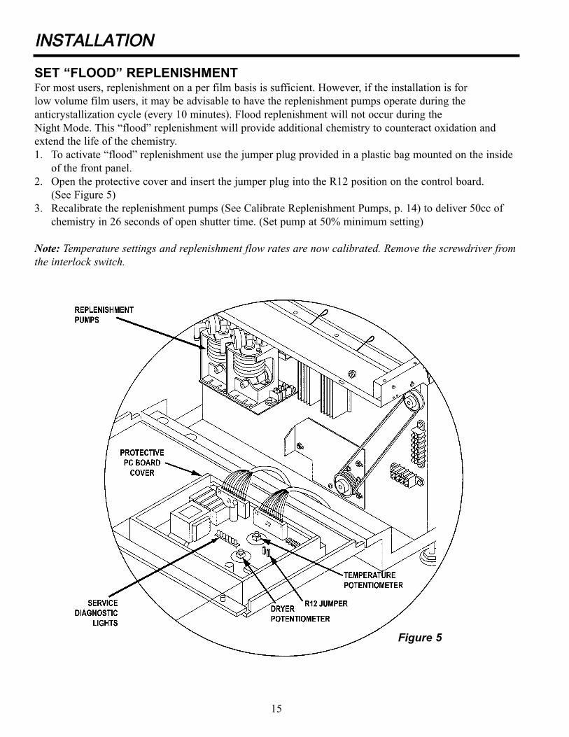
SET “FLOOD” REPLENISHMENTFor most users, replenishment on a per film basis is sufficient. However, if the installation is for
low volume film users, it may be advisable to have the replenishment pumps operate during the
anticrystallization cycle (every 10 minutes). Flood replenishment will not occur during the
Night Mode. This “flood” replenishment will provide additional chemistry to counteract oxidation and
extend the life of the chemistry.
1. To activate “flood” replenishment use the jumper plug provided in a plastic bag mounted on the inside
of the front panel.
2. Open the protective cover and insert the jumper plug into the R12 position on the control board.
(See Figure 5)
3. Recalibrate the replenishment pumps (See Calibrate Replenishment Pumps, p. 14) to deliver 50cc of
chemistry in 26 seconds of open shutter time. (Set pump at 50% minimum setting)
Note: Temperature settings and replenishment flow rates are now calibrated. Remove the screwdriver fromthe interlock switch.
IINNSSTTAALLLLAATTIIOONN
Figure 5
15

CHECK DRIVE BELT TENSION1. Using light finger pressure (approximately 1/2 lb. of force). Press one side of the drive belt at
midspan. It should deflect approximately 3/16”. (See Figure 6)
2. If the drive belt deflects more or less than the 3/16”, then the tension needs to be adjusted. First
loosen the nuts on the motor mounting plate. Then shift the motor left to tighten the belt, right to
loosen the belt.
3. Retighten the nuts when the desired tension has been reached.
IINNSSTTAALLLLAATTIIOONN
Figure 6
16
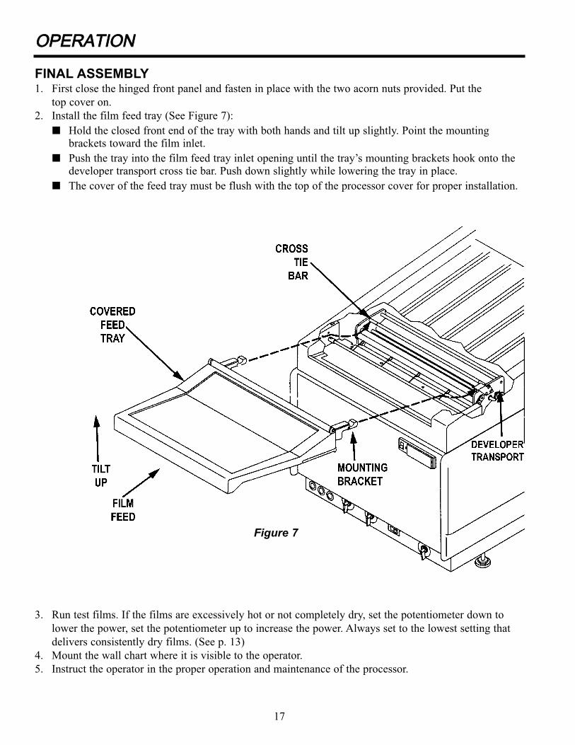
FINAL ASSEMBLY1. First close the hinged front panel and fasten in place with the two acorn nuts provided. Put the
top cover on.
2. Install the film feed tray (See Figure 7):
O Hold the closed front end of the tray with both hands and tilt up slightly. Point the mounting brackets toward the film inlet.
O Push the tray into the film feed tray inlet opening until the tray’s mounting brackets hook onto the developer transport cross tie bar. Push down slightly while lowering the tray in place.
O The cover of the feed tray must be flush with the top of the processor cover for proper installation.
3. Run test films. If the films are excessively hot or not completely dry, set the potentiometer down to
lower the power, set the potentiometer up to increase the power. Always set to the lowest setting that
delivers consistently dry films. (See p. 13)
4. Mount the wall chart where it is visible to the operator.
5. Instruct the operator in the proper operation and maintenance of the processor.
OOPPEERRAATTIIOONN
17
Figure 7
OOPPEERRAATTIIOONN
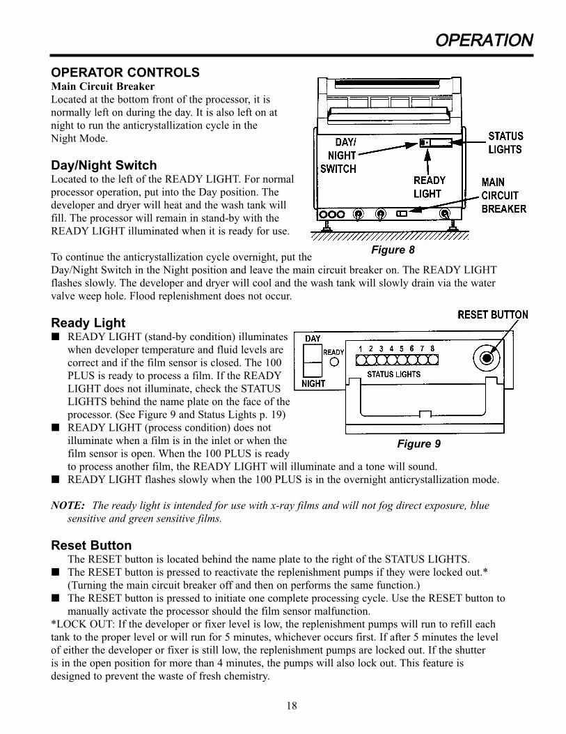
OPERATOR CONTROLSMain Circuit Breaker
Located at the bottom front of the processor, it is
normally left on during the day. It is also left on at
night to run the anticrystallization cycle in the
Night Mode.
Day/Night SwitchLocated to the left of the READY LIGHT. For normal
processor operation, put into the Day position. The
developer and dryer will heat and the wash tank will
fill. The processor will remain in stand-by with the
READY LIGHT illuminated when it is ready for use.
To continue the anticrystallization cycle overnight, put the
Day/Night Switch in the Night position and leave the main circuit breaker on. The READY LIGHT
flashes slowly. The developer and dryer will cool and the wash tank will slowly drain via the water
valve weep hole. Flood replenishment does not occur.
Ready LightO READY LIGHT (stand-by condition) illuminates
when developer temperature and fluid levels are
correct and if the film sensor is closed. The 100
PLUS is ready to process a film. If the READY
LIGHT does not illuminate, check the STATUS
LIGHTS behind the name plate on the face of the
processor. (See Figure 9 and Status Lights p. 19)
O READY LIGHT (process condition) does not
illuminate when a film is in the inlet or when the
film sensor is open. When the 100 PLUS is ready
to process another film, the READY LIGHT will illuminate and a tone will sound.
O READY LIGHT flashes slowly when the 100 PLUS is in the overnight anticrystallization mode.
NOTE: The ready light is intended for use with x-ray films and will not fog direct exposure, blue sensitive and green sensitive films.
Reset ButtonThe RESET button is located behind the name plate to the right of the STATUS LIGHTS.
O The RESET button is pressed to reactivate the replenishment pumps if they were locked out.*
(Turning the main circuit breaker off and then on performs the same function.)
O The RESET button is pressed to initiate one complete processing cycle. Use the RESET button to
manually activate the processor should the film sensor malfunction.
*LOCK OUT: If the developer or fixer level is low, the replenishment pumps will run to refill each
tank to the proper level or will run for 5 minutes, whichever occurs first. If after 5 minutes the level
of either the developer or fixer is still low, the replenishment pumps are locked out. If the shutter
is in the open position for more than 4 minutes, the pumps will also lock out. This feature is
designed to prevent the waste of fresh chemistry.
18
Figure 8
Figure 9

LIGHTN0. FUNCTION STATUS
1 Developer Temperature ON CorrectDEV TEMP OFF Low
Flashing Slowly (15 per min) HighFlashing Rapidly (120 per min) Temperature sensor
open or short circuited
2 Dryer Temperature ON CorrectDRYER OK OFF Low
Flashing Slowly (15 per min) HighFlashing Rapidly (120 per min) Temperature sensor
open or short circuited
3 Film Sensor ON Film in inletFLM FEED OFF No film in inlet
Flashing Film sensor not closingbetween films; replenishment pumps locked out.
4 Developer Level ON CorrectDEV LEVL OFF Low
Flashing Low; replenishment pumpunable to refill within 5minutes; replenishmentpumps locked out
5 Fixer Level ON CorrectFIX LEVL OFF Low
Flashing Low; replenishment pumpsunable to refill within 5minutes; replenishmentpumps locked out
6 Water Level ON CorrectWATER OK 0FF High or love; See Light
No. 7 & 8.
7 High Water Level ON Water level highWATER HI OFF See Light No 6 & 8
FLASHING Water level was high
8 Low Water Level ON Water level lowWATER LO OFF See Light No. 6
OOPPEERRAATTIIOONN
STATUS LIGHTSThese lights are located behind the name plate panel. (See Figure 9) Refer to these lights if there is a prob-
lem when operating the 100 PLUS. Review the lights, note whether there is light "on", light "off", or light
"flashing". Then look in the Status column in the chart below for the explanation. For example, if READY
LIGHT is not on and Light No. 4, Developer Level, is flashing, the chemistry level in the developer tank is
low. A possible cause is an empty developer container, or a developer drain valve that is not completely
closed.
19
OOPPEERRAATTIIOONN
DAILY OPERATIONTo insure that optimum films are delivered by the 100 PLUS, it is suggested that a Quality Control
Program be adopted similar to the procedures detailed by the American College of Radiology (ACR).
At Start of Day1. Turn the water supply valve ON.
2. Check chemistry levels in developer and fixer replenishment containers and fill as required.
3. Turn main circuit breaker ON and put DAY/NIGHT switch into DAY position.
4. In approximately 15-20 minutes, the READY LIGHT illuminates.
5. Insert a 14 x 17 cleaning film into the film inlet.
To Process Film1. The READY LIGHT must be illuminated before film is processed.
2. Open the feed tray and slide the film into the film inlet. For all film sizes, guide the film along
either edge of the feed tray. Film should enter the film inlet as straight as possible. The READY
LIGHT will go out and the processor will automatically activate.
3. Before processing another film wait until the READY LIGHT illuminates and the tone sounds.
4. When the last film exits the dryer, the 100 PLUS automatically returns to standby.
At End of Day1. Shut the water supply valve OFF.
2. If the anticrystallization cycle is to be operated overnight, put the Day/Night switch into the Night
position and leave the main circuit breaker ON.
3. If the anticrystallization cycle is not to be operated overnight, turn the main circuit breaker OFF.
4. Leave the covered feed tray closed at the end of the day.
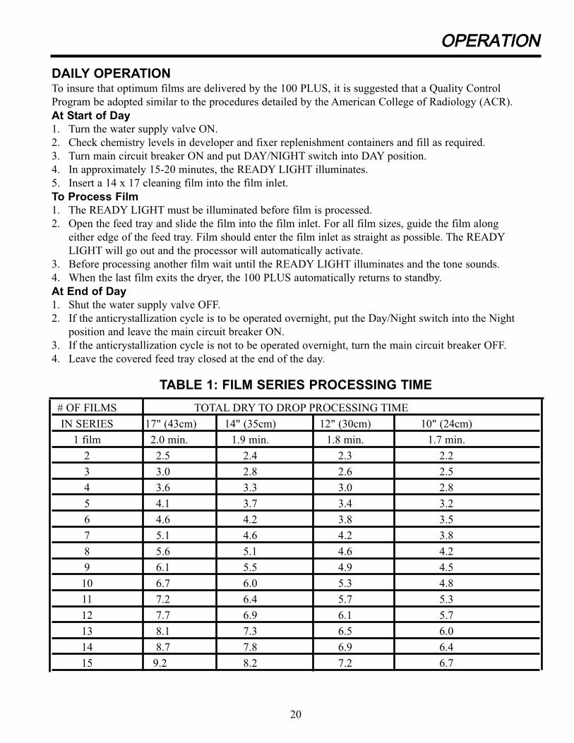
# OF FILMS TOTAL DRY TO DROP PROCESSING TIME
IN SERIES 17" (43cm) 14" (35cm) 12" (30cm) 10" (24cm)
1 film 2.0 min. 1.9 min. 1.8 min. 1.7 min.
2 2.5 2.4 2.3 2.2
3 3.0 2.8 2.6 2.5
4 3.6 3.3 3.0 2.8
5 4.1 3.7 3.4 3.2
6 4.6 4.2 3.8 3.5
7 5.1 4.6 4.2 3.8
8 5.6 5.1 4.6 4.2
9 6.1 5.5 4.9 4.5
10 6.7 6.0 5.3 4.8
11 7.2 6.4 5.7 5.3
12 7.7 6.9 6.1 5.7
13 8.1 7.3 6.5 6.0
14 8.7 7.8 6.9 6.4
15 9.2 8.2 7.2 6.7
TABLE 1: FILM SERIES PROCESSING TIME
20

SSEERRVVIICCEE -- MMAAIINNTTEENNAANNCCEE
DAILYProcess a 14 x 17 cleaning film when the READY LIGHT illuminates to remove overnight chemistry
build-up from the rollers, and to provide fresh developer and fixer to the tanks.
MONTHLY1. Remove the developer, fixer and wash transports from the 100 PLUS and open all the drain valves
(located on the front bottom of the processor) to drain all fluids from the tanks.
2. Rinse each wet transport under running water and wipe the rollers and built-in crossovers with a non-
abrasive sponge. Pay close attention to the trailing edge of the crossover.
3. While holding the gears under running water, turn the main drive gear making sure that the transport
rollers turn freely.
NOTE: Use non-abrasive cleaning materials ONLY on the transport rollers and crossover guides. Abrasive materials, including SCOTCH BRITE, can scratch the film guide surfaces and interfere with smooth film transport.
4. Check all rollers, o-rings, gears and turnaround guides for proper tension and to make sure the
fittings are secure.
5. With all drain valves open, pour water into each tank to flush out the lines.
6. Wipe the inside surfaces of the developer, fixer and wash tanks with separate sponges. Begin with the
developer tank, followed by the fixer and then the wash tank to prevent possible cross-contamination
of the developer. Use only non-abrasive sponges with water or systems cleaner when cleaning the
transports and tanks.
7. Flush lines again. Once the lines have completely drained, close the valves.
8. Add chemistry.
NOTE: If systems cleaner has been used, drain valves must be opened and the entire line must be thoroughly rinsed with water.
QUARTERLY1. Perform all steps as for monthly cleaning.
2. In addition to the above, a more thorough cleaning of the transports is recommended:
O Remove the retainer clips from all the idler studs and slide the gears off. (See Transport Assemblies, p. 48-57)
O Clean the idler studs and gears. Replace the gears and retainer clips onto the idler studs.
O Clean the dryer transport's bottom turnaround guide. For better access to this surface, one or both of the bottom roller pairs may be removed and then reinstalled.
This procedure should be done by a Service Technician.3. Clean and relubricate the front-most saddle bearing, at the front end of the main drive shaft, with white
lithium grease or equivalent.
21

SSEERRVVIICCEE -- SSTTAATTUUSS//SSEERRVVIICCEE DDIIAAGGNNOOSSTTIICC LLIIGGHHTTSS
HOW TO USE THE STATUS / SERVICE DIAGNOSTIC LIGHTSTwo unique features of the 100 PLUS are the STATUS LIGHTS located behind the name plate on the front
panel and the SERVICE DIAGNOSTIC LIGHTS located on the inside of the front cover.
The STATUS LIGHTS inform the operator of the temperature and fluid levels and the status of the film
sensor. These lights should be reviewed first when a problem arises. The SERVICE DIAGNOSTIC
LIGHTS are used by the Service Technician. Familiarity with these lights will help in pinpointing the
problem area. Both sets of lights are used to gather information about the processor and then to resolve
the problem.
The following relates the STATUS LIGHTS to the SERVICE DIAGNOSTIC LIGHTS during different
modes: WARM-UP; STANDBY; OPEN SHUTTER; ANTICRYSTALLIZATION and NIGHT MODE.
Review the summary for each chart.
WARM-UP [DAY MODE ONLY]
#9 #1 #2 #3 #4 #5 #6 #7 #8
Ready Dev Dryer Film Dev Fix Water Water Water
Light Temp Temp Inlet Level Level Level High Low
Off Off Off Off On (off) On (off) Off Off On
#16 #15 #14 #13 #12 #11 #10
Dryer Water Dev Dryer Drive Recirc Repl
Fan Solenoid Heater Heater Motor Pump Pump
Off On (off) Off (on) On (off) Off On Off (on)
Summary: Initially during warm-up, the only lights illuminated on the STATUS LIGHTS panel are the
WATER LOW, DEV LEVEL, and FIX LEVEL (provided the chemistry levels are sufficient).
If chemistry levels are low, the DEV LEVEL and FIX LEVEL lights will be out as well.
On the main electronics PC board, the DRYER FAN, DRIVE MOTOR, and REPL PUMP lights remain
off, indicating no power is being applied to these loads during warm-up. The DRYER HEATER light will
illuminate before the DEV HEATER light and then cycle once the dryer temperature has reached a
set-back position. The RECIRC PUMP light will be illuminated during warm-up.
The WATER SOLENOID light will be on.
22

SSEERRVVIICCEE -- SSTTAATTUUSS//SSEERRVVIICCEE DDIIAAGGNNOOSSTTIICC LLIIGGHHTTSS
Summary: On the STATUS LIGHTS panel, all temperature and chemistry level lights are illuminated,
indicating conditions are correct for processing. The FILM INLET light will not illuminate until a film is
entered into the processor. The WATER LEVEL light is on. As the wash tank drains via the weep hole, the
WATER LEVEL light will extinguish and the WATER LOW light will illuminate when the water level
goes below the low level water sensor. At this point the water solenoid opens over a predetermined amount
of time and refills the wash tank.
On the main electronics PC board, the DRYER FAN, DRIVE MOTOR, and REPL PUMP service lights
are off until a film is entered. The DEV HEATER and DRYER HEATER lights illuminate, indicating
the processor is cycling to maintain proper temperature levels. The RECIRC PUMP light illuminates in
conjunction with the DEV HEATER light indicating the movement of heated chemistry throughout the
bath. The WATER SOLENOID illuminates as the wash water level is maintained.
STANDBY [DAY MODE]
#9 #1 #2 #3 #4 #5 #6 #7 #8
Ready Dev Dryer Film Dev Fix Water Water Water
Light Temp Temp Inlet Level Level Level High Low
On On On Off On On On Off Off
#16 #15 #14 #13 #12 #11 #10
Dryer Water Dev Dryer Drive Recirc Repl
Fan Solenoid Heater Heater Motor Pump Pump
Off Off (on) Off (on) Off (on) Off Off (on) Off
23
SSEERRVVIICCEE -- SSTTAATTUUSS//SSEERRVVIICCEE DDIIAAGGNNOOSSTTIICC LLIIGGHHTTSS
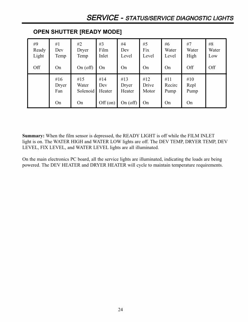
OPEN SHUTTER [READY MODE]
#9 #1 #2 #3 #4 #5 #6 #7 #8
Ready Dev Dryer Film Dev Fix Water Water Water
Light Temp Temp Inlet Level Level Level High Low
Off On On (off) On On On On Off Off
#16 #15 #14 #13 #12 #11 #10
Dryer Water Dev Dryer Drive Recirc Repl
Fan Solenoid Heater Heater Motor Pump Pump
On On Off (on) On (off) On On On
Summary: When the film sensor is depressed, the READY LIGHT is off while the FILM INLET
light is on. The WATER HIGH and WATER LOW lights are off. The DEV TEMP, DRYER TEMP, DEV
LEVEL, FIX LEVEL, and WATER LEVEL lights are all illuminated.
On the main electronics PC board, all the service lights are illuminated, indicating the loads are being
powered. The DEV HEATER and DRYER HEATER will cycle to maintain temperature requirements.
24

SSEERRVVIICCEE -- SSTTAATTUUSS//SSEERRVVIICCEE DDIIAAGGNNOOSSTTIICC LLIIGGHHTTSS
Summary: If the 100 Plus has been in STANDBY for more than ten minutes, the processor automatically
activates. The rollers turn and are re-wet with the chemical solutions to prevent build-up on the rollers.
The FILM INLET and WATER HIGH lights are not illuminated. The WATER LEVEL and WATER LOW
will cycle on and off as wash water levels are maintained. All other STATUS LIGHTS are illuminated.
On the main electronics PC board, the DRYER FAN light is not illuminated. The WATER SOLENOID,
DEV HEATER, and DRYER HEATER will cycle to maintain proper temperature and fluid levels. The
REPL PUMP light will illuminate for approximately ten seconds while pumps inject fresh chemistry into
the baths if the processor is set for FLOOD REPLENISHMENT.
The DRIVE MOTOR will illuminate while the rollers turn.
ANTICRYSTALLIZATION CYCLE
#9 #1 #2 #3 #4 #5 #6 #7 #8
Ready Dev Dryer Film Dev Fix Water Water Water
Light Temp Temp Inlet Level Level Level High Low
On On On Off On On On (off) Off Off (on)
#16 #15 #14 #13 #12 #11 #10
Dryer Water Dev Dryer Drive Recirc Repl
Fan Solenoid Heater Heater Motor Pump Pump
Off Off (on) Off (on) Off (on) On Off Off (on)
25

Summary: While in the NIGHT MODE, the READY LIGHT flashes. In addition, the WATER LOW
light on the STATUS LIGHTS panel is on because the wash water will have drained from the water tank to
retard the growth of algae. The DEV LEVEL and FIX LEVEL lights are on. If chemistry falls below the
level of the sensors, the DEV LEVEL and FIX LEVEL will be off.
On the main electronics PC board, all the service lights, with the exception of the DRIVE MOTOR light,
are not illuminated. The DRIVE MOTOR light illuminates every ten minutes indicating that rollers are
turning to prevent chemistry build-up overnight.
NIGHT MODE
#9 #1 #2 #3 #4 #5 #6 #7 #8
Ready Dev Dryer Film Dev Fix Water Water Water
Light Temp Temp Inlet Level Level Level High Low
Flashing Off Off Off On On Off Off On
#16 #15 #14 #13 #12 #11 #10
Dryer Water Dev Dryer Drive Recirc Repl
Fan Solenoid Heater Heater Motor Pump Pump
Off Off Off Off Off (on) Off Off
SSEERRVVIICCEE -- SSTTAATTUUSS//SSEERRVVIICCEE DDIIAAGGNNOOSSTTIICC LLIIGGHHTTSS
26

TTRROOUUBBLLEE SSHHOOOOTTIINNGG -- TTAABBLLEE OOFF CCOONNTTEENNTTSS
The Trouble Shooting Guide is organized into three sections in a step-by-step problem solving approach.Equipment Problems deal with the installation and set-up of the processor and the mechanical problemsthat may occur over time with heavy usage. Film Problems and Electrical Problems require familiaritywith the processor and electronics. The Film Problems section serves as the "bridge" between theEquipment and the Electrical sections since problems may first be evidenced on the processed film. TheService Technician should review the Trouble Shooting to become familiar with problems encounteredand their solutions before servicing the 100 PLUS.
EQUIPMENT PROBLEMS1. Top cover assembly not seated properly . . . . . . . . . . . . . . . . . . . . . . . . . . . . . . . . . . . . . . .282. Side panels not secured properly . . . . . . . . . . . . . . . . . . . . . . . . . . . . . . . . . . . . . . . . . . . . .283. Front panel not secure . . . . . . . . . . . . . . . . . . . . . . . . . . . . . . . . . . . . . . . . . . . . . . . . . . . . . .284. Covered feed chute not seating properly . . . . . . . . . . . . . . . . . . . . . . . . . . . . . . . . . . . . . . .285. Condensation on film inlet tray . . . . . . . . . . . . . . . . . . . . . . . . . . . . . . . . . . . . . . . . . . . . . .286. Transport tight / squeaking / binding . . . . . . . . . . . . . . . . . . . . . . . . . . . . . . . . . . . . . . . . . .287. Films not feeding properly . . . . . . . . . . . . . . . . . . . . . . . . . . . . . . . . . . . . . . . . . . . . . . . . . .288. Noise from main drive motor . . . . . . . . . . . . . . . . . . . . . . . . . . . . . . . . . . . . . . . . . . . . . . . .289. Scratches / lines on films . . . . . . . . . . . . . . . . . . . . . . . . . . . . . . . . . . . . . . . . . . . . . . . . . . .2910. False fluid level indications . . . . . . . . . . . . . . . . . . . . . . . . . . . . . . . . . . . . . . . . . . . . . . . . .2911. Films wet or tacky . . . . . . . . . . . . . . . . . . . . . . . . . . . . . . . . . . . . . . . . . . . . . . . . . . . . . . . .29
FILM PROBLEMSPre-Processing Related Problems1. Pressure marks . . . . . . . . . . . . . . . . . . . . . . . . . . . . . . . . . . . . . . . . . . . . . . . . . . . . . . . . . . .302. Static . . . . . . . . . . . . . . . . . . . . . . . . . . . . . . . . . . . . . . . . . . . . . . . . . . . . . . . . . . . . . . . . . . .303. Non-linear scratch marks . . . . . . . . . . . . . . . . . . . . . . . . . . . . . . . . . . . . . . . . . . . . . . . . . . .304. Irregular marks . . . . . . . . . . . . . . . . . . . . . . . . . . . . . . . . . . . . . . . . . . . . . . . . . . . . . . . . . . .305. Fogged film . . . . . . . . . . . . . . . . . . . . . . . . . . . . . . . . . . . . . . . . . . . . . . . . . . . . . . . . . . . . . .30Processing Related Film Problems1. Water marks / wet film . . . . . . . . . . . . . . . . . . . . . . . . . . . . . . . . . . . . . . . . . . . . . . . . . . . . .302. Linear patterns . . . . . . . . . . . . . . . . . . . . . . . . . . . . . . . . . . . . . . . . . . . . . . . . . . . . . . . . . . .313. Roller marks . . . . . . . . . . . . . . . . . . . . . . . . . . . . . . . . . . . . . . . . . . . . . . . . . . . . . . . . . . . . .314. Dryer marks . . . . . . . . . . . . . . . . . . . . . . . . . . . . . . . . . . . . . . . . . . . . . . . . . . . . . . . . . . . . .31Chemistry-Related Film Problems1. Changes in speed and contrast (MD/DD) values . . . . . . . . . . . . . . . . . . . . . . . . . . . . . . . . .322. Changes in base fog (B+F) . . . . . . . . . . . . . . . . . . . . . . . . . . . . . . . . . . . . . . . . . . . . . . . . . .32Exposure-Related Film Problems1. Films . . . . . . . . . . . . . . . . . . . . . . . . . . . . . . . . . . . . . . . . . . . . . . . . . . . . . . . . . . . . . . . . . . .322. Equipment . . . . . . . . . . . . . . . . . . . . . . . . . . . . . . . . . . . . . . . . . . . . . . . . . . . . . . . . . . . . . . .32
ELECTRICAL PROBLEMS1. Dryer too hot during the process cycle . . . . . . . . . . . . . . . . . . . . . . . . . . . . . . . . . . . . . . . . .332. Dryer too cool or does not heat at all during the process cycle . . . . . . . . . . . . . . . . . . . . . .333. Developer chemistry is too hot . . . . . . . . . . . . . . . . . . . . . . . . . . . . . . . . . . . . . . . . . . . . . . .344. Developer is too cool or does not heat during the process cycle . . . . . . . . . . . . . . . . . . . . .355. Main drive motor does not operate during the process cycle . . . . . . . . . . . . . . . . . . . . . . .366. Dryer fan does not operate during the process cycle . . . . . . . . . . . . . . . . . . . . . . . . . . . . . .367. Recirculation pump does not circulate chemistry during the process cycle . . . . . . . . . . . .368. Replenishment pumps do not pump when the film shutter is open . . . . . . . . . . . . . . . . . . .379. Processor does not power up when main circuit breaker is turned on . . . . . . . . . . . . . . . . .3710. Water solenoid does not operate during the process cycle . . . . . . . . . . . . . . . . . . . . . . . . . .3811. Process cycle does not activate when film sensor is depressed . . . . . . . . . . . . . . . . . . . . . .38
27

SSEERRVVIICCEE -- TTRROOUUBBLLEE SSHHOOOOTTIINNGG
EEqquuiippmmeenntt PPrroobblleemmss1. TOP COVER ASSEMBLY NOT SEATED PROPERLY
O Lift cover up and fit rear edge first, then front edge.
O Make sure that the two acorn nuts are installed securing front panel.
2. SIDE PANELS NOT SECURED PROPERLY
O Two metal clips that clip over the lower flange of the metal chassis and two spring-loaded bullet clips which snap under the side rail flanges with a fastening screw in the top front may
be adjusted by loosening and repositioning. Left and right side panels are not interchangeable.
3. FRONT PANEL NOT SECURE
O Replace missing acorn nuts and / or threaded inserts.
O Check hinge for interference
4. COVERED FEED CHUTE NOT SEATING PROPERLY
O Remove and follow the installation procedure in Final Assembly, p. 17.
O Make sure feed tray is not hooked on to color coded material on cross tie.
5. CONDENSATION ON FILM INLET TRAY
O Leave film inlet tray cover closed at night.
O Run cleaning film.
6. TRANSPORT TIGHT/SQUEAKING / BINDING
O Follow monthly maintenance instructions. (See Maintenance, p. 21)
O Check all gears, o-rings, retaining clips, and bearings.
O Check for squareness. If not square, adjust by placing the transport on a flat surface and loosen the screws on the cross ties. When the transport is square, retighten the screws. Turn
each main drive gear to check for free movement.
7. FILMS NOT FEEDING PROPERLY
O Check feed tray and film sensor for correct alignment.
O Feed films along one edge of feed tray.
O Guide into developer entrance rollers.
O Allow tone to sound and READY LIGHT to illuminate before feeding next film.
8. NOISE FROM MAIN DRIVE MOTOR
O Check saddle bearing at front of main drive shaft near developer transport for lubrication.
O Check main drive belt tension and adjust motor mounting plate. (See Check Drive Belt Tension, p.16)
O Check main drive motor.
28
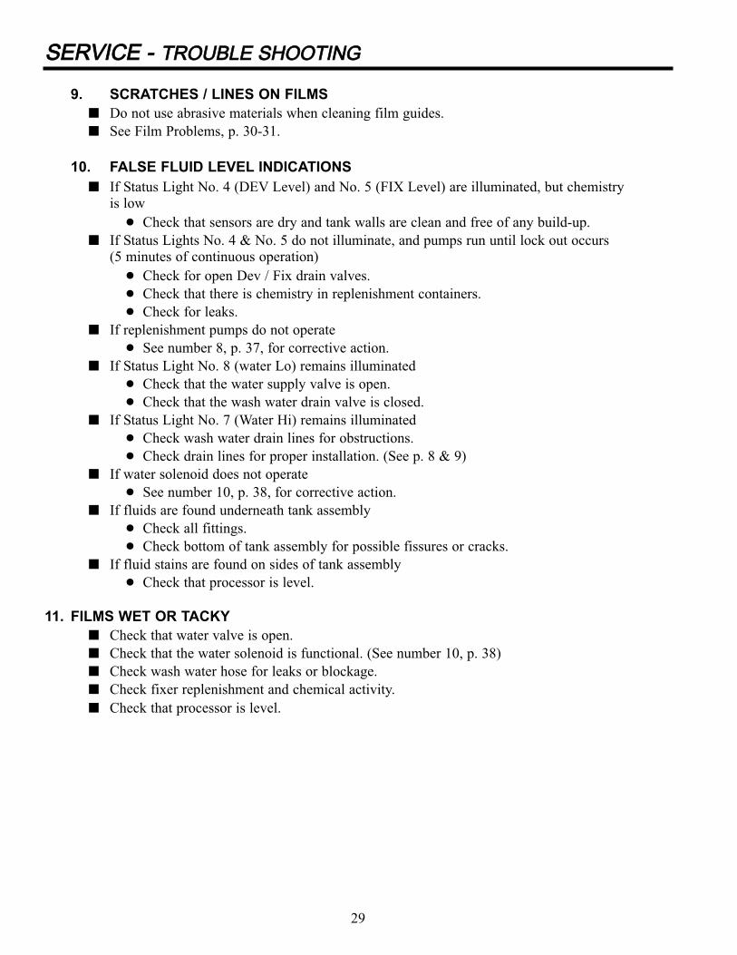
9. SCRATCHES / LINES ON FILMS
O Do not use abrasive materials when cleaning film guides.
O See Film Problems, p. 30-31.
10. FALSE FLUID LEVEL INDICATIONS
O If Status Light No. 4 (DEV Level) and No. 5 (FIX Level) are illuminated, but chemistryis low
! Check that sensors are dry and tank walls are clean and free of any build-up.
O If Status Lights No. 4 & No. 5 do not illuminate, and pumps run until lock out occurs(5 minutes of continuous operation)
! Check for open Dev / Fix drain valves.
! Check that there is chemistry in replenishment containers.
! Check for leaks.
O If replenishment pumps do not operate
! See number 8, p. 37, for corrective action.
O If Status Light No. 8 (water Lo) remains illuminated
! Check that the water supply valve is open.
! Check that the wash water drain valve is closed.
O If Status Light No. 7 (Water Hi) remains illuminated
! Check wash water drain lines for obstructions.
! Check drain lines for proper installation. (See p. 8 & 9)
O If water solenoid does not operate
! See number 10, p. 38, for corrective action.
O If fluids are found underneath tank assembly
! Check all fittings.
! Check bottom of tank assembly for possible fissures or cracks.
O If fluid stains are found on sides of tank assembly
! Check that processor is level.
11. FILMS WET OR TACKY
O Check that water valve is open.
O Check that the water solenoid is functional. (See number 10, p. 38)
O Check wash water hose for leaks or blockage.
O Check fixer replenishment and chemical activity.
O Check that processor is level.
29
SSEERRVVIICCEE -- TTRROOUUBBLLEE SSHHOOOOTTIINNGG

SSEERRVVIICCEE -- TTRROOUUBBLLEE SSHHOOOOTTIINNGG
FFIILLMM PPRROOBBLLEEMMSSDeveloped x-ray film is useful in identifying radiographic quality problems that are related to the process-
ing cycle. Examine the film for telltale marks and signs. Then look below to identify the problem which
could be related to any of the following: Pre-Processing, Processing, Chemistry or Exposure.
PPRREE--PPRROOCCEESSSSIINNGG RREELLAATTEEDD FFIILLMM PPRROOBBLLEEMMSS1. Pressure marks
O Plus densities due to rough handling prior to exposure and processing.
O Minus densities due to rough handling after exposure and prior to processing.
! Avoid bending and flexing film prior to and after processing.2. Static
O Plus densities due to electric discharge on film surface; may be "tree" static or"smudge" static.
! Maintain proper level of (30-50%) humidity in the darkroom.3. Non-linear scratch marks
O Minus densities due to emulsion being scraped from substrate.
! Avoid placing film on rough surfaces and/or sliding film.4. Irregular marks
O Minus densities due to particles on surfaces of intensifying screens or pick-off from rollers.
! Use screen cleaner with a lint-free gauze pad or other lint-free cloth, as recommended by screen manufacturers.
5. Fogged film
O Plus densities due to darkroom light leaks or film exposed to light.
! Perform light leak test for darkroom.
O Plus densities due to improper safelight or prolonged safelight exposure.
! Follow film manufacturer's recommendation for proper safe lighting.
O Plus densities due to outdated or improperly stored film.
! Replace outdated film.
PPRROOCCEESSSSIINNGG RREELLAATTEEDD FFIILLMM PPRROOBBLLEEMMSS1. Water marks/wet film
O Dark, crescent-shaped marks generally seen only in reflective light and found on the leadingedge of the film.
O Dark spots, generally seen only in reflective light, may exhibit a line running back towards thetrailing edge of the film.
! Overall film wet/tacky to touch.For all of the above conditions check the following:! Check o-ring tension on wash/dryer exit/entrance roller pairs.
! Check wash water overflow and drain line for blockage.
! Check high water level sensor.
! Check dryer setting and lamp resistance.
! Check dryer thermistor.
! Check that processor is level.
30

SSEERRVVIICCEE -- TTRROOUUBBLLEE SSHHOOOOTTIINNGG
2. Linear patterns
O Plus density lines, approximately 1/8" apart: running in direction of film travel. Generally caused by film contact with the curved guide in the developer transport or developer/fixer crossover. Lines
are seen in transmitted light and are on the top side of the film.
! Check alignment of guides to roller nip.
! Check guides for burrs.
O Minus density lines, approximately 1/8" apart; running in direction of film travel. Generally caused by contact with fixer/wash/dry transports cross-overs, dryer bottom turnaround, or flat guide in
dryer. Lines are seen in reflected and/or transmitted light and can be on either surface of film.
! Check guides for burrs.
! Identify top/bottom side of film.Top side: check alignment of guides to roller nip between transports.
Bottom side: check alignment of bottom turnaround and flat guide to respective roller pair nip.
3. Roller marks
O Plus density lines running perpendicular to film travel and repeating the length of the film. Generally caused by developer rollers that are not straight or by gear interference.
! Clean rack assembly.
! Check for missing o-rings and/or correct transport tension.
! Check for correct roller pairing in transport, ie. rubber/rubber, rubber/plastic or plastic/plastic.
! Check gaps between rollers in each pair.
O Plus density lines running the length of the film which vary in size and distance from each other. Generally caused by developer rollers that have high or low spots around the circumference of
the roller.
! Check for correct roller pairing in rack ie. rubber/rubber, rubber/plastic or plastic/plastic.
! Check for gaps between rollers in each pair.4. Dryer marks
O Triangular marks found on trailing edge of film. Generally seen in both transmitted and reflected light. Referred to as lamp guard heat marks.
! Check for burrs on lamp reflector.
! Check position of lamp guards.
! Check lamp guard alignment.
O Diffuse lines, approximately 1/8" apart and seen in reflected lighting in direction of film feed. Generally found on top side of film. Referred to as heat marks from dryer crossover.
! Check dryer rack alignment.
! Check for burrs on guides.
! Lower dryer temperature.
O Diffuse pattern, plus density.Generally seen in reflected and transmitted light. Referred to as “shore lining”.
! Lower dryer temperature.
! Check dryer air boots.
! Check wash water level.
! Check for correct roller pairing in wash/dry exit/entrance rollers.
! Check that processor is level.
31

SSEERRVVIICCEE -- TTRROOUUBBLLEE SSHHOOOOTTIINNGG
CCHHEEMMIISSTTRRYY--RREELLAATTEEDD FFIILLMM PPRROOBBLLEEMMSSConsult film and chemistry manufacturers specifications for recommended temperature, replenishment
rates, and developer immersion times prior to troubleshooting the 100 Plus.
1. Changes in speed and contrast (MD/DD) values
O Sensitometry results above or below acceptable range typically result from:
! Developer temperature too high/low.
! Replenishment rates too high/low.
! Developer solution “hot” or exhausted.
! Change in film lot/brand/type.
! Change in chemistry brand.
! Processing cycle too long/short.
2. Changes in base fog (B+F)
O Sensitometry results ABOVE acceptable values typically result from:
! Change in film lot/brand/type.
! Age of film.
! Exposure to light /ionizing radiation.
! Developer temperature too high.
! Over-replenishment.
! Inadequate storage.
EEXXPPOOSSUURREE--RREELLAATTEEDD FFIILLMM PPRROOBBLLEEMMSS1. Films
O Over/under exposed:
! Exposure techniques incorrect.
! Change in film/screen combination.
! Use of beam-restricting devices, ie. grids.
2. Equipment
O Test x-ray equipment for:
! Incomplete exposures.
! Decreased mR output.
! Inadequate line voltages.
32

SSEERRVVIICCEE -- TTRROOUUBBLLEE SSHHOOOOTTIINNGG
33
EElleeccttrriiccaall PPrroobblleemmssWARNING!Tests in this section must be performed only by qualified service technicians.Safety interlocks will be bypassed and hazardous voltages will be present.
To perform many of the tests detailed below, remove the top cover and “defeat” the interlock switch. This
is accomplished by inserting the blade of a screwdriver into the interlock switch opening. Point the blade
toward the rear of the processor when inserting.
When resistance or continuity is to be tested, we recommend that the processor be unplugged from its
electrical receptacle.
1. DRYER TOO HOT DURING THE PROCESS CYCLE
CChheecckk SSEERRVVIICCEE DDIIAAGGNNOOSSTTIICC LLIIGGHHTT ## 1133 [[DDRRYY]]..A. If light is flashing test voltage at dryer connector between pins 1 and 2 for 230 VAC. .
Perform this test with the connector plugged in. (See Table 2, p. 39)
1. If 230 VAC is present and pulses in synch with light, measure dryer heater lamp resistance at
dryer connector between pins 1 and 2.
a. If resistance is 91 ohms or 182 ohms, replace defective lamp(s). b. If resistance is 61 ohms, lamps are OK. Turn dryer potentiometer setting down.
2. If 230 VAC is present but does not pulse, test voltage between J2-3 and J2-5 for 230 VAC.
a. If voltage stays less than 50 VAC, replace main PC board assembly.b. If voltage pulses in synch with light or remains 230 VAC, replace triac.
CAUTION: Do not turn on processor unless all three terminals are securely attached to triac.Otherwise, main PC board assembly will be severely damaged!
B. If light is constant measure dryer thermistor resistance. Disconnect connector J1 from mainPC board assembly and measure between pins 9 and 10.
(See Table 3, p. 40) .
1. If in tolerance, replace main PC board assembly.
2. If out of tolerance, measure dryer thermistor resistance at dryer connector between
pins 5 and 6.
a. If out of tolerance, replace thermistor.b. If in tolerance, check for poor connections in thermistor circuit between connector J1
and dryer connector.2. DRYER TOO COOL OR DOES NOT HEAT AT ALL DURING THE PROCESS CYCLE.
QUICK CHECK: Led #2 Not Flashing (ON steady)If the air from the dryer, or the dryer exit rollers appear to be very hot while Status Light
No. 2 (DRYER TEMP) is on, the dryer potentiometer may simply be set too high.
Turn it down. If the light is flashing, follow the procedure below.
QUICK CHECKIf the films exiting the dryer are slightly damp or tacky to the touch, and Status Light
No. 2 (DRYER TEMP) is off, the dryer potentiometer may simply be set too low.
Turn it up. If the light remains out, follow the procedure below.

SSEERRVVIICCEE -- TTRROOUUBBLLEE SSHHOOOOTTIINNGG
CChheecckk SSEERRVVIICCEE DDIIAAGGNNOOSSTTIICC LLIIGGHHTT ## 1133 ((DDRRYY))..A. If light is flashing or on constantly, test voltage at dryer connector between pins 1 and 2.
Perform this test with the connector plugged in.
1. If no voltage is present, test voltage between J2-3 and J2-5 for 230 VAC.
a. If voltage is constant at 230 VAC, replace main PC board assembly.b. If voltage pulses or is less than 50 VAC, replace triac.
CAUTION: Do not turn on processor unless all three terminals are securely attached to triac.Otherwise, main PC board assembly will be severely damaged!
2. If 230 VAC is present and pulses in synch with light, measure dryer heater lamp resistance at
dryer connector between pins 1 and 2.
a. If resistance is 91 ohms or 182 ohms, replace defective lamp(s).b. If resistance is 61 ohms, lamps are OK. Turn dryer potentiometer setting up.
B. If light does not illuminate, turn dryer potentiometer up. If light still does not illuminate,
measure dryer thermistor resistance. Disconnect connector J-1 from main PC board assembly
and measure between pins 9 and 10. (See Table 3, p. 40)
1. If in tolerance, replace main PC board assembly.
2. If out of tolerance, measure dryer thermistor resistance at dryer connector between pins 5 and 6.
a. If out of tolerance, replace thermistor.b. If in tolerance, check for poor connections in thermistor circuit between connector J-1 and
dryer connector.
3. DEVELOPER CHEMISTRY IS TOO HOT
CChheecckk SSEERRVVIICCEE DDIIAAGGOONNSSTTIICC LLIIGGHHTT ## 1144 [[DDEEVV]]..
A. If light is flashing test voltage between TB2-3 and TB 1-3 for 230 VAC.
1. If 230 VAC is present and pulses in synch with light, developer temperature may be set too
high. Measure and turn down if necessary. (See Set Developer Temperature, p.13)
2. If 230 VAC is present but does not pulse, test voltage between J2-1 and J2-2 for 230 VAC.
a. If voltage stays less than 50 VAC, replace main PC board assembly.b. If voltage pulses with light, replace triac PIN 115578.
CAUTION: Do not turn on processor unless all three terminals arc securely attached to triac.Otherwise, main PC board assembly will be severely damaged!
34
QUICK CHECKIf the processed films are too dark, and Status Light No. 1 is on, developer temperature may
be set too high. Measure developer temperature and turn down if necessary. If temperature
remains high, follow the procedure below.

SSEERRVVIICCEE -- TTRROOUUBBLLEE SSHHOOOOTTIINNGG
B. If light is on constantly, measure developer thermistor resistance. Disconnect J1 from the main PC
board assembly and measure between pins 11 and 12. (See Table 3. p. 40)
1. If out of tolerance, replace thermistor.
2. If in tolerance, replace main PC board assembly.
4. DEVELOPER IS TOO COOL OR DOES NOT HEAT DURING THE PROCESS CYCLE.
CChheecckk SSEERRVVIICCEE DDIIAAGGNNOOSSTTIICC LLIIGGHHTT ## 1144 [[DDEEVV]]..A. If light is flashing or on constantly, test voltage between J2-2 and J2-5 for 230 VAC.
1. If voltage pulses or is constant, check voltage between TB2-3 and TB1-3 for 230 VAC.
a. If no voltage is present, check connections at TB1 and TB2.b. If voltage is present, measure developer heater resistance.
! If resistance is not 106 ohms, replace developer heater.2. If no voltage is present, test voltage between J2-1 and J2-2 for 230 VAC.
a. If voltage is constant at 230 VAC, replace main PC board assembly.b. If voltage pulses or is less than 50 VAC, replace triac.
CAUTION: Do not turn on processor unless all three terminals are securely attached to triac. Otherwise, main PC board assembly will be severely damaged!
B. If light does not illuminate, turn developer potentiometer up. (See Set Developer Temperature,
p. 13) If it still does not illuminate, measure developer thermistor resistance. Disconnect connector
J1 from main PC board assembly and measure between pins 11 and 12. (See Table 3, p. 40)
1. If out of tolerance, replace thermistor.
2. If in tolerance, replace main PC board assembly.
35
QUICK CHECKIf the films are underdeveloped, and Status Light No. 1 is on, developer temperature may be set to
low. Measure developer temperature and increase if necessary.
If Status Lights No. l and 4 are off, developer chemistry level may be low, and will not heat as a
result. Add chemistry, then press Reset button or turn main circuit breaker on and off to initiate the
process cycle. If temperature does not increase and there is chemistry in the tanks, follow the proce-
dure below.

SSEERRVVIICCEE -- TTRROOUUBBLLEE SSHHOOOOTTIINNGG
5. MAIN DRIVE MOTOR DOES NOT OPERATE DURING THE PROCESS CYCLE
CChheecckk SSEERRVVIICCEE DDIIAAGGNNOOSSTTIICC LLIIGGHHTT ## 1122 [[DDRRIIVVEE]]..
A. If light is not illuminated, replace main PC board assembly.
B. If light is illuminated, test voltage between J2-8 and TB2-2 for 230 VAC.
1. If no voltage is present, check TB2-2 connection. If connection is good, replace main
PC board assembly.
2. If 230 VAC is present, test voltage between TB1-2 and TB2-2 for 230 VAC.
a. If no voltage is present, check connection at TB1 -2.b. If 230 VAC is present, replace main drive motor.
6. DRYER FAN DOES NOT OPERATE DURING THE PROCESS CYCLE
CChheecckk SSEERRVVIICCEE DDIIAAGGNNOOSSTTIICC LLIIGGHHTT ## 1166 [[FFAANN]]..
A. If light is not illuminated, replace main PC board assembly.
B. If light is illuminated, test voltage between J2-11 and TB2-2 for 230 VAC.
1. If no voltage is present, check TB2-2 connection. If connection is good, replace main
PC board assembly.
2. If 230 VAC is present, test voltage between TB1-5 and TB2-2.
a. If no voltage is present, check conection at TB1-5.b. If 230 VAC is present, replace fan.
7. RECIRCULATION PUMP DOES NOT CIRCULATE CHEMISTRY DURING THE
PROCESS CYCLE.
QQUUIICCKK CCHHEECCKKIf chemistry circulates in the developer and not the fixer, or vice versa, the circulator motor
is operating but one side of the pump has a mechanical problem. Check for blockages in the
recirculating lines. If there is a blockage, pour warm water into the pump inlet. If the blockage
still does not clear, replace the pump assembly.
If there is no blockage, follow the procedure below.
CChheecckk SSEERRVVIICCEE DDIIAAGGNNOOSSTTIICC LLIIGGHHTT ## 1111 [[CCIIRRCC]]..A. If light is not illuminated, replace main PC board assembly.
B. If light is illuminated, test voltage between J2-9 and TB2-1.
1. If no voltage is present, check connection at TB1-4.
2. If 230 VAC is present, replace recirculation pump assembly.
36

SSEERRVVIICCEE -- TTRROOUUBBLLEE SSHHOOOOTTIINNGG
8. REPLENISHMENT PUMPS DO NOT PUMP WHEN THE FILM SHUTTER IS OPEN.
QQUUIICCKK CCHHEECCKKCheck Status Lights Nos. 4 and 5. If one or the other light is flashing, replenishment pumps are locked
out. This means that the processor has unsuccessfully tried to fill tanks for 5 minutes. If the
replenishment containers are empty, fill them. If the drain valves are open, close them. To reset
replenishment pumps, turn main circuit breaker off and on. If the pumps still do not run.
Follow the procedure below.
CChheecckk SSEERRVVIICCEE DDIIAAGGNNOOSSTTIICC LLIIGGHHTT ## ll00 [[RREEPPLL]]..A. If light is not illuminated, replace main PC board assembly.
B. If light is illuminated but pumps do not operate, test voltage between J2-10 and TB2-2 for 230 VAC
with shutter open.
1. If no voltage is present, check TB1-1 connection. If connection is good, replace main PC board
assembly.
2. If 230 VAC is present, test voltage between TB1-1 and TB2-2 for 230 VAC.
a. If no voltage is present, check connection at TB1-1.
b. If 230 VAC is present, replace replenishment pump.C. If light is illuminated and pumps operate, but no chemistry is being pumped
1. Check replenishment containers. If empty, fill.
2. Check replenishment tubing. If kinked or bent, straighten.
3. Check pump valves. If dirty, clean.
9. PROCESSOR DOES NOT POWER UP WHEN MAIN CIRCUIT BREAKER
IS TURNED ON.
QQUUIICCKK CCHHEECCKKCheck that there is electrical power to the outlet and that the processor is plugged in. If the processor
does not power up, follow the procedure below.
CChheecckk TTHHEE TTRRIIPPPPEERR PPOOSSTT:: RREEMMOOVVEE TTHHEE TTOOPP CCOOVVEERR AANNDD DDEEFFEEAATT TTHHEE IINNTTEERRLLOOCCKK SSWWIITTCCHH
((SSeeee WWaarrnniinngg,, pp..3333]]A. If processor powers up, determine why tripper post in top cover does not activate interlock switch.
B. If processor does not power up, disconnect plug from power receptacle. Test interlock switch and
main circuit breaker for continuity. If defective, replace.
C. If interlock switch and main circuit breaker are OK, test voltage between J2-5 and J2-6 for
230 VAC.
1. If no voltage is present, test all terminals and wiring from TB-4 to J2-5 and J2-6.
2. If 230 VAC is present, replace fuse on main PC board assembly.
3. If this does not solve problem, replace main PC board assembly.
37

SSEERRVVIICCEE -- TTRROOUUBBLLEE SSHHOOOOTTIINNGG
10. WATER SOLENOID DOES NOT OPERATE DURING THE PROCESS CYCLE.
QQUUIICCKK CCHHEECCKKBe sure that the water supply valve is turned on and that the screen filter at the solenoid entry
is not clogged. If the water solenoid still does not turn on, follow the procedure below.
CCHHEECCKK SSTTAATTUUSS LLIIGGHHTT NNOO.. 77 [[WWAATTEERR HHIIGGHH]] AANNDD NNOO.. 66 [[WWAATTEERR LLEEVVEELL]]
A. If No. 7 is illuminated, the water solenoid is locked out. Disconnect the wire from
terminal J1-7.
1. If No. 7 flashes and No. 6 comes on
a. Check for wet level sensor.b. Check for accidental grounding of level sensor.c. Check drain line blockage or air locks.
2. If No. 7 remains illuminated, replace main PC board assembly.
Don't forget to reconnect wire to terminal J1-7.
B. If No. 6 is illuminated, check Service Diagnostic Light #15 (WAT).
1. If light is not illuminated, replace main PC board assembly.
2. If light is illuminated, test voltage between J2-12 and TB2-2 for 230 VAC.
a. If no voltage is present, change main PC board assembly.b. If 230 VAC is present, check for 230 VAC at solenoid terminals.
* If 230 VAC is present, change solenoid.
** If no voltage is present, check wiring and connections.
11. PROCESS CYCLE DOES NOT ACTIVATE WHEN FILM SENSOR IS DEPRESSED.
CCHHEECCKK SSTTAATTUUSS LLIIGGHHTT NNOO.. 33 [[FFIILLMM IINNLLEETT]]
A. If light illuminates when film sensor is depressed, replace main PC board assembly.
B. If light does not illuminate when film sensor is depressed, test voltage between J1-1 and J1-3
for 5 VDC.
1. If no voltage is present, replace main PC board assembly.
2. If 5 VDC is present, test voltage between J1-2 and J1-3 for 5 VDC with film sensor depressed.
a. If 5 VDC is present, replace main PC board assembly.
b. If no voltage is present
* Check electrical connections to film sensor PC board.
** Check that film sensor flag withdraws from inside optic sensor when film sensor is
depressed.
! If film sensor flag operates correctly, replace film sensor PC board assembly.
38

SSEERRVVIICCEE -- TTRROOUUBBLLEE SSHHOOOOTTIINNGG
TTAABBLLEE 22:: VVOOLLTTAAGGEE AANNDD RREESSIISSTTAANNCCEE VVAALLUUEESS
Loads Test Points Voltage Resistance
230 VAC
6A 50/60 Hz
Main Drive J2-8 to TB2-2 230 VAC
Motor TB1-2 to TB2-2 230 VAC
Dryer Heater DRYER CONNECTOR PINS
1 & 2 230 VAC 61 ohms
J2-3 to J2-5 w/SERVICE LED ON 230 VAC
J2-3 to J2-5 w/SERVICE LED ON 230 VAC
J1-9 to J1-10
THERMISTOR PINS 5 & 6 See Table 3
(black and red wires)
Dryer Fan J2-11 to TB2-2 230VAC
TB1-5 to TB2-2 230VAC
Developer TB2-3 to TB1-3 230 VAC
Heater J2-1 to J2-2 w/SERVICE LED OFF 230 VAC
J2-2 to J2-5 w/SERVCE LED ON 230 VAC 106 ohms
THERMISTOR J1-11 to J1-12 See Table 3
Recirc Pump J2-9 to TB2-1 230 VAC
TB1-4 to TB2-1 230 VAC
Replenishment TB1-1 to TB2-2 230 VAC
Pumps J2-10 to TB2-2 230 VAC
Water Solenoid J2-12 to TB2-2 230 VAC
Hi Level Sensor J1-7 to ground infinity
Lo Level Sensor J1-6 to ground infinity
Interlock J2-5 - J2-6 230 VAC
Switch
Film Sensor J1-1 - J1-3 5 VDC
PC Board J1-2 - J1-3 w/SENSOR ACTIVATED 5 VDC
39

SSEERRVVIICCEE -- TTRROOUUBBLLEE SSHHOOOOTTIINNGG
TTAABBLLEE 33:: TTHHEERRMMIISSTTOORR TTEEMMPPEERRAATTUURREE // RREESSIISSTTAANNCCEE VVAALLUUEESS
Temperature (°F) Resistance (ohms)
80 4735
85 4150
90 3710
95 3288
100 2940
110 2534
120 2143
130 1875
140 1450
40

PPAARRTTSS // AASSSSEEMMBBLLIIEESS -- TTaabbllee ooff CCoonntteennttss
100 PLUS EXTERIOR . . . . . . . . . . . . . . . . . . . . . . . . . . . . . . . . . . . . . . . . . . . . . .42-43
100 PLUS INTERIOR . . . . . . . . . . . . . . . . . . . . . . . . . . . . . . . . . . . . . . . . . . . . . . .44-45
FILM SENSOR ASSEMBLY . . . . . . . . . . . . . . . . . . . . . . . . . . . . . . . . . . . . . . . . . .46
CHASSIS BULKHEAD . . . . . . . . . . . . . . . . . . . . . . . . . . . . . . . . . . . . . . . . . . . . . .47
DEVELOPER TRANSPORT . . . . . . . . . . . . . . . . . . . . . . . . . . . . . . . . . . . . . . . . . .48-49
FIXER TRANSPORT . . . . . . . . . . . . . . . . . . . . . . . . . . . . . . . . . . . . . . . . . . . . . . .50-51
WASH TRANSPORT . . . . . . . . . . . . . . . . . . . . . . . . . . . . . . . . . . . . . . . . . . . . . . .52-53
DRYER TRANSPORT . . . . . . . . . . . . . . . . . . . . . . . . . . . . . . . . . . . . . . . . . . . . . .54-57
41
PPAARRTTSS // AASSSSEEMMBBLLIIEESS
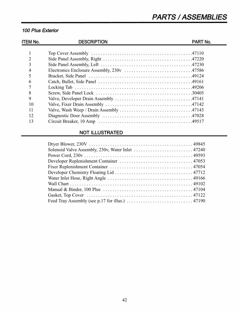
110000 PPIIuuss EExxtteerriioorr
IITTEEMM NNoo.. DDEESSCCRRIIPPTTIIOONN PPAARRTT NNoo..
1 Top Cover Assembly . . . . . . . . . . . . . . . . . . . . . . . . . . . . . . . . . . . . . . . . . . .47110
2 Side Panel Assembly, Right . . . . . . . . . . . . . . . . . . . . . . . . . . . . . . . . . . . . . .47220
3 Side Panel Assembly, Left . . . . . . . . . . . . . . . . . . . . . . . . . . . . . . . . . . . . . . .47230
4 Electronics Enclosure Assembly, 230v . . . . . . . . . . . . . . . . . . . . . . . . . . . . .47586
5 Bracket, Side Panel . . . . . . . . . . . . . . . . . . . . . . . . . . . . . . . . . . . . . . . . . . . .49124
6 Catch, Bullet, Side Panel . . . . . . . . . . . . . . . . . . . . . . . . . . . . . . . . . . . . . . . .49161
7 Locking Tab . . . . . . . . . . . . . . . . . . . . . . . . . . . . . . . . . . . . . . . . . . . . . . . . . .49206
8 Screw, Side Panel Lock . . . . . . . . . . . . . . . . . . . . . . . . . . . . . . . . . . . . . . . . .30405
9 Valve, Developer Drain Assembly . . . . . . . . . . . . . . . . . . . . . . . . . . . . . . . . .47141
10 Valve, Fixer Drain Assembly . . . . . . . . . . . . . . . . . . . . . . . . . . . . . . . . . . . . .47142
11 Valve, Wash Weep / Drain Assembly . . . . . . . . . . . . . . . . . . . . . . . . . . . . . . .47143
12 Diagnostic Door Assembly . . . . . . . . . . . . . . . . . . . . . . . . . . . . . . . . . . . . . .47028
13 Circuit Breaker, 10 Amp . . . . . . . . . . . . . . . . . . . . . . . . . . . . . . . . . . . . . . . .49517
NNOOTT IILLLLUUSSTTRRAATTEEDD
Dryer Blower, 230V . . . . . . . . . . . . . . . . . . . . . . . . . . . . . . . . . . . . . . . . . . . . 49845
Solenoid Valve Assembly, 230v, Water Inlet . . . . . . . . . . . . . . . . . . . . . . . . . 47240
Power Cord, 230v . . . . . . . . . . . . . . . . . . . . . . . . . . . . . . . . . . . . . . . . . . . . . . 49593
Developer Replenishment Container . . . . . . . . . . . . . . . . . . . . . . . . . . . . . . . 47053
Fixer Replenishment Container . . . . . . . . . . . . . . . . . . . . . . . . . . . . . . . . . . . 47054
Developer Chemistry Floating Lid . . . . . . . . . . . . . . . . . . . . . . . . . . . . . . . . . 47712
Water Inlet Hose, Right Angle . . . . . . . . . . . . . . . . . . . . . . . . . . . . . . . . . . . . 49166
Wall Chart . . . . . . . . . . . . . . . . . . . . . . . . . . . . . . . . . . . . . . . . . . . . . . . . . . . . 49102
Manual & Binder, 100 Plus . . . . . . . . . . . . . . . . . . . . . . . . . . . . . . . . . . . . . . 47104
Gasket, Top Cover . . . . . . . . . . . . . . . . . . . . . . . . . . . . . . . . . . . . . . . . . . . . . 47122
Feed Tray Assembly (see p.17 for illus.) . . . . . . . . . . . . . . . . . . . . . . . . . . . . 47190
42
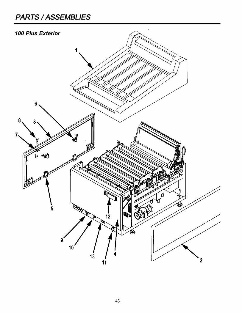
PPAARRTTSS // AASSSSEEMMBBLLIIEESS
43
100 Plus Exterior

PPAARRTTSS // AASSSSEEMMBBLLIIEESS
110000 PPlluuss IInntteerriioorr
IITTEEMM NNoo.. DDEESSCCRRIIPPTTIIOONN,, PPAARRTT NNoo..
1 Developer Transport Assembly . . . . . . . . . . . . . . . . . . . . . . . . . .47810
2 Fixer Transport Assembly . . . . . . . . . . . . . . . . . . . . . . . . . . . . . .47820
3 Wash Transport Assembly . . . . . . . . . . . . . . . . . . . . . . . . . . . . .47830
4 Dryer Transport Assembly, 230v . . . . . . . . . . . . . . . . . . . . . . . . .47765
5 Tank, Drilled . . . . . . . . . . . . . . . . . . . . . . . . . . . . . . . . . . . . . . . . .47302
6 Drive Shaft Assembly . . . . . . . . . . . . . . . . . . . . . . . . . . . . . . . . . .49120
7 Replenishment Tube . . . . . . . . . . . . . . . . . . . . . . . . . . . . . . . . . .49142
8 Leveling Foot . . . . . . . . . . . . . . . . . . . . . . . . . . . . . . . . . . . . . . . .43106
8A Sleeve, Leveling Foot . . . . . . . . . . . . . . . . . . . . . . . . . . . . . . . . .47848
9 Heater, Developer, 230v . . . . . . . . . . . . . . . . . . . . . . . . . . . . . . .49575
10 Recirculator Pump, Dual Head, 230v . . . . . . . . . . . . . . . . . . . . .47304
11 Splash Guard Assembly . . . . . . . . . . . . . . . . . . . . . . . . . . . . . . . .47163
12 Bearing, Saddle . . . . . . . . . . . . . . . . . . . . . . . . . . . . . . . . . . . . . .49307
13 Bracket, Wash Tube Support . . . . . . . . . . . . . . . . . . . . . . . . . . . .47124
14 Panel, Dryer Support / Locator . . . . . . . . . . . . . . . . . . . . . . . . . .47727
15 Dryer, Rear Support Assembly . . . . . . . . . . . . . . . . . . . . . . . . . .47737
16 Bracket, High Level Sensor . . . . . . . . . . . . . . . . . . . . . . . . . . . . .47318
17 Control PC Board Assembly, 230v . . . . . . . . . . . . . . . . . . . . . . . .47582
18 Cover, PC Board Protector . . . . . . . . . . . . . . . . . . . . . . . . . . . . .49126
44

PPAARRTTSS // AASSSSEEMMBBLLIIEESS
45
100 Plus Interior

PPAARRTTSS // AASSSSEEMMBBLLIIEESS
FFiillmm IInnlleett AAsssseemmbbllyy
IITTEEMM NNoo.. DDEESSCCRRIIPPTTIIOONN PPAARRTT NNoo..
1 Film Sensor Actuator Assembly . . . . . . . . . . . . . . . . . . . . . . . . . . . . . . .47798
2 Coupling, Right . . . . . . . . . . . . . . . . . . . . . . . . . . . . . . . . . . . . . . . . . . . .47181
3 Coupling, Left . . . . . . . . . . . . . . . . . . . . . . . . . . . . . . . . . . . . . . . . . . . . .47182
4 Splash Guard . . . . . . . . . . . . . . . . . . . . . . . . . . . . . . . . . . . . . . . . . . . . . .47199
5 Cover, Interlock Switch . . . . . . . . . . . . . . . . . . . . . . . . . . . . . . . . . . . . .47184
6 Cover, Film Sensor . . . . . . . . . . . . . . . . . . . . . . . . . . . . . . . . . . . . . . . . .47185
7 Interlock Switch . . . . . . . . . . . . . . . . . . . . . . . . . . . . . . . . . . . . . . . . . . .47519
8 PC Board Assembly, Film Sensor . . . . . . . . . . . . . . . . . . . . . . . . . . . . .47980
9 Actuator, Film Sensor . . . . . . . . . . . . . . . . . . . . . . . . . . . . . . . . . . . . . . .47465
46
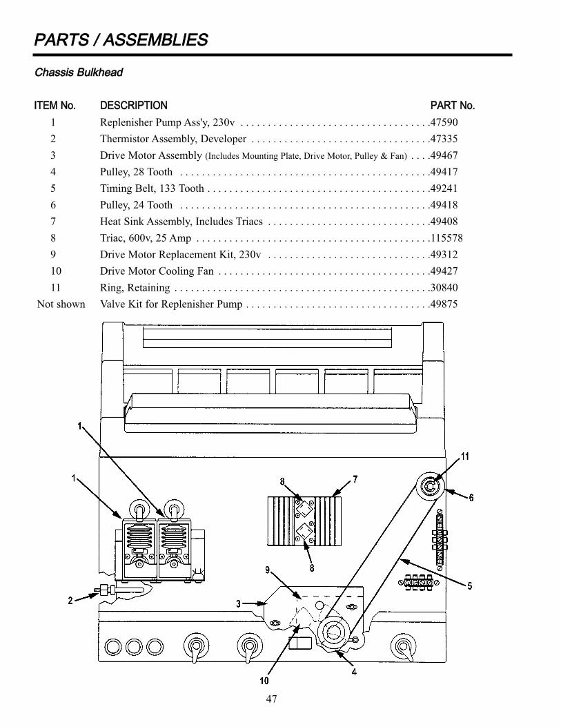
PPAARRTTSS // AASSSSEEMMBBLLIIEESS
CChhaassssiiss BBuullkkhheeaadd
IITTEEMM NNoo.. DDEESSCCRRIIPPTTIIOONN PPAARRTT NNoo..
1 Replenisher Pump Ass'y, 230v . . . . . . . . . . . . . . . . . . . . . . . . . . . . . . . . . . .47590
2 Thermistor Assembly, Developer . . . . . . . . . . . . . . . . . . . . . . . . . . . . . . . . .47335
3 Drive Motor Assembly (Includes Mounting Plate, Drive Motor, Pulley & Fan) . . . .49467
4 Pulley, 28 Tooth . . . . . . . . . . . . . . . . . . . . . . . . . . . . . . . . . . . . . . . . . . . . . .49417
5 Timing Belt, 133 Tooth . . . . . . . . . . . . . . . . . . . . . . . . . . . . . . . . . . . . . . . . .49241
6 Pulley, 24 Tooth . . . . . . . . . . . . . . . . . . . . . . . . . . . . . . . . . . . . . . . . . . . . . .49418
7 Heat Sink Assembly, Includes Triacs . . . . . . . . . . . . . . . . . . . . . . . . . . . . . .49408
8 Triac, 600v, 25 Amp . . . . . . . . . . . . . . . . . . . . . . . . . . . . . . . . . . . . . . . . . . .115578
9 Drive Motor Replacement Kit, 230v . . . . . . . . . . . . . . . . . . . . . . . . . . . . . .49312
10 Drive Motor Cooling Fan . . . . . . . . . . . . . . . . . . . . . . . . . . . . . . . . . . . . . . .49427
11 Ring, Retaining . . . . . . . . . . . . . . . . . . . . . . . . . . . . . . . . . . . . . . . . . . . . . . .30840
Not shown Valve Kit for Replenisher Pump . . . . . . . . . . . . . . . . . . . . . . . . . . . . . . . . . .49875
47

PPAARRTTSS // AASSSSEEMMBBLLIIEESS
DDeevveellooppeerr TTrraannssppoorrtt
IITTEEMM NNoo.. DDEESSCCRRIIPPTTIIOONN PPAARRTT NNoo..
1 Bushing, Roller Spring ..................................................................................49811
2 Bushing, Roller Spring, Square .....................................................................49831
3 O-Ring, Size 120 ...........................................................................................49823
4 Retainer Clip, Roller Shaft, 1/4” ...................................................................49807
5 Retainer Clip, Idlers/Drive Shaft, 3/8” ..........................................................49808
6 Stud, Idler.......................................................................................................49822
7 Bearing, 3/8", Nylon......................................................................................49816
8 Pin, Cotter, 1/16” x 1” Lg..............................................................................30798
9 Pin, Cotter, 1/16” x 1-1/2” Lg .......................................................................30799
10 Drive Shaft Rod .............................................................................................49817
11 Gear, worm ....................................................................................................49818
12 Gear, Spur, .75” P.D., ‘D’ Bore......................................................................49801
13 Gear, Spur, 1.25” P.D., 3/8” Bore..................................................................49802
14 Gear, Drive, 1.5” P.D., 3/8” Bore ..................................................................49803
15 Roller, Rubber, Standard, Black Color ..........................................................49828
17 Guide, Flat, Film Transport ...........................................................................49815
18 Guide, Curved, Film Transport......................................................................49814
19 Cross Tie, Wet Transport ...............................................................................49827
20 Guide, Crossover, In/Out, Film Transport .....................................................47868
21 Gear, Spur, 2.0” P.D., 3/8” Bore....................................................................49804
22 Collar..............................................................................................................30800
23 Gear, Spur, .75” P.D., 3/8” Bore....................................................................49805
26 Side Plate, Developer Transport ....................................................................47836
28 Bracket, Feedtray Hold Down .......................................................................47123
48

PPAARRTTSS // AASSSSEEMMBBLLIIEESS
49
Developer Transport

PPAARRTTSS // AASSSSEEMMBBLLIIEESS
FFiixxeerr TTrraannssppoorrtt
IITTEEMM NNoo.. DDEESSCCRRIIPPTTIIOONN PPAARRTT NNoo..
1 Bushing, Roller Spring..................................................................................49811
2 Bushing, Roller Spring, Square.....................................................................49831
3 0-Ring, Size 120............................................................................................49823
4 Retainer Clip, Roller Shaft, 1/4”...................................................................49807
5 Retainer Clip, Idlers/Drive Shaft, 3/8”..........................................................49808
6 Stud, Idler ......................................................................................................49822
7 Bearing, 3/8”, Nylon .....................................................................................49816
8 Pin, Cotter, 1/16” x 1” Lg .............................................................................30798
9 Pin, Cotter, 1/16” x 1-1/2” Lg.......................................................................30799
10 Drive Shaft Rod.............................................................................................49817
11 Gear, Worm....................................................................................................49818
12 Gear, Spur, .75” P.D., 'D' Bore ......................................................................49801
13 Gear, Spur, 1.25” P.D., 3/8” Bore .................................................................49802
14 Gear, Drive, 1.5” P.D., 3/8” Bore..................................................................49803
15 Roller, Rubber, Standard, Black Color..........................................................49828
16 Roller, Plastic, Golden Color ........................................................................49872
17 Guide, Flat, Film Transport ...........................................................................49815
18 Guide, Arched, Film Transport......................................................................49824
19 Cross Tie, Wet Transport ...............................................................................49827
20 Guide, Crossover, In/Out, Film Transport ....................................................47868
21 Gear, Spur, 2.0” P.D., 3/8” Bore ...................................................................49804
22 Collar .............................................................................................................30800
26 Side Plate, Fixer / Wash Transport................................................................47837
50

PPAARRTTSS // AASSSSEEMMBBLLIIEESS
51
Fixer Transport
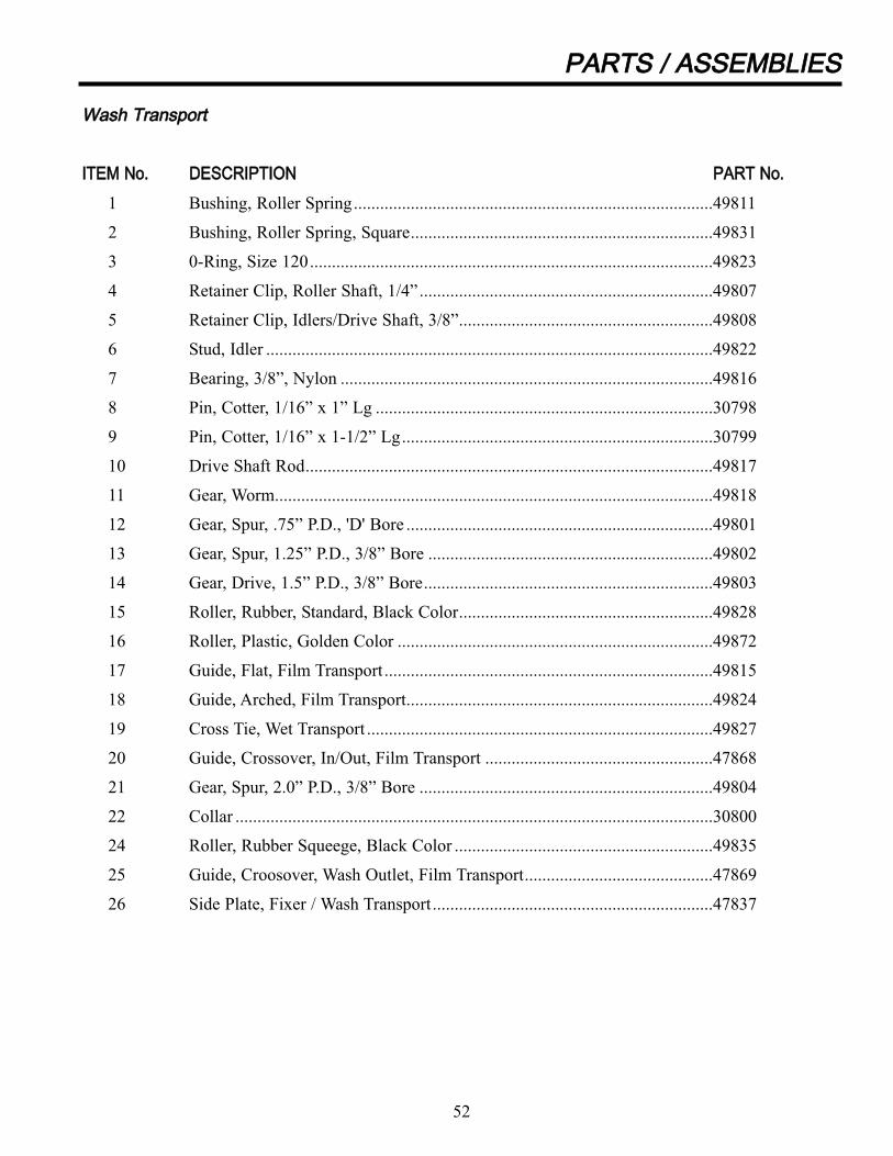
PPAARRTTSS // AASSSSEEMMBBLLIIEESS
WWaasshh TTrraannssppoorrtt
IITTEEMM NNoo.. DDEESSCCRRIIPPTTIIOONN PPAARRTT NNoo..
1 Bushing, Roller Spring..................................................................................49811
2 Bushing, Roller Spring, Square.....................................................................49831
3 0-Ring, Size 120............................................................................................49823
4 Retainer Clip, Roller Shaft, 1/4”...................................................................49807
5 Retainer Clip, Idlers/Drive Shaft, 3/8”..........................................................49808
6 Stud, Idler ......................................................................................................49822
7 Bearing, 3/8”, Nylon .....................................................................................49816
8 Pin, Cotter, 1/16” x 1” Lg .............................................................................30798
9 Pin, Cotter, 1/16” x 1-1/2” Lg.......................................................................30799
10 Drive Shaft Rod.............................................................................................49817
11 Gear, Worm....................................................................................................49818
12 Gear, Spur, .75” P.D., 'D' Bore ......................................................................49801
13 Gear, Spur, 1.25” P.D., 3/8” Bore .................................................................49802
14 Gear, Drive, 1.5” P.D., 3/8” Bore..................................................................49803
15 Roller, Rubber, Standard, Black Color..........................................................49828
16 Roller, Plastic, Golden Color ........................................................................49872
17 Guide, Flat, Film Transport ...........................................................................49815
18 Guide, Arched, Film Transport......................................................................49824
19 Cross Tie, Wet Transport ...............................................................................49827
20 Guide, Crossover, In/Out, Film Transport ....................................................47868
21 Gear, Spur, 2.0” P.D., 3/8” Bore ...................................................................49804
22 Collar .............................................................................................................30800
24 Roller, Rubber Squeege, Black Color ...........................................................49835
25 Guide, Croosover, Wash Outlet, Film Transport...........................................47869
26 Side Plate, Fixer / Wash Transport................................................................47837
52

PPAARRTTSS // AASSSSEEMMBBLLIIEESS
53
Wash Transport
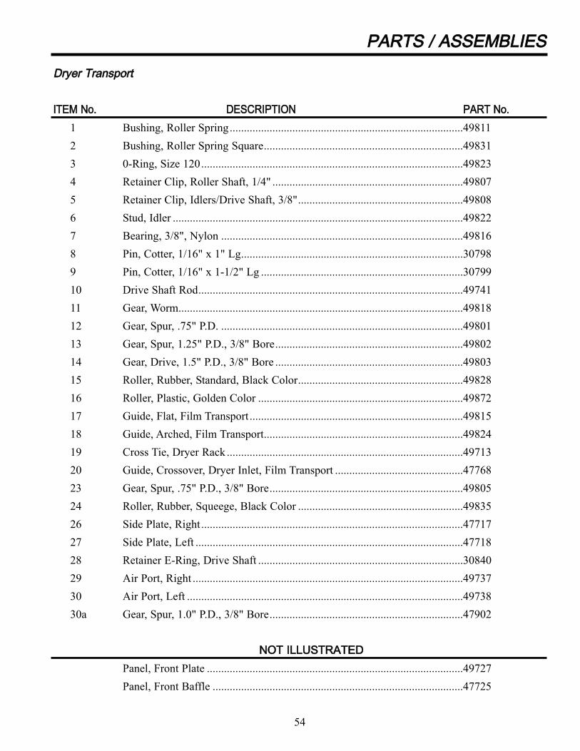
54
PPAARRTTSS // AASSSSEEMMBBLLIIEESS
DDrryyeerr TTrraannssppoorrtt
IITTEEMM NNoo.. DDEESSCCRRIIPPTTIIOONN PPAARRTT NNoo..
1 Bushing, Roller Spring..................................................................................49811
2 Bushing, Roller Spring Square......................................................................49831
3 0-Ring, Size 120............................................................................................49823
4 Retainer Clip, Roller Shaft, 1/4" ...................................................................49807
5 Retainer Clip, Idlers/Drive Shaft, 3/8"..........................................................49808
6 Stud, Idler ......................................................................................................49822
7 Bearing, 3/8", Nylon .....................................................................................49816
8 Pin, Cotter, 1/16" x 1" Lg..............................................................................30798
9 Pin, Cotter, 1/16" x 1-1/2" Lg .......................................................................30799
10 Drive Shaft Rod.............................................................................................49741
11 Gear, Worm....................................................................................................49818
12 Gear, Spur, .75" P.D. .....................................................................................49801
13 Gear, Spur, 1.25" P.D., 3/8" Bore..................................................................49802
14 Gear, Drive, 1.5" P.D., 3/8" Bore ..................................................................49803
15 Roller, Rubber, Standard, Black Color..........................................................49828
16 Roller, Plastic, Golden Color ........................................................................49872
17 Guide, Flat, Film Transport ...........................................................................49815
18 Guide, Arched, Film Transport......................................................................49824
19 Cross Tie, Dryer Rack ...................................................................................49713
20 Guide, Crossover, Dryer Inlet, Film Transport .............................................47768
23 Gear, Spur, .75" P.D., 3/8" Bore....................................................................49805
24 Roller, Rubber, Squeege, Black Color ..........................................................49835
26 Side Plate, Right............................................................................................47717
27 Side Plate, Left ..............................................................................................47718
28 Retainer E-Ring, Drive Shaft ........................................................................30840
29 Air Port, Right ...............................................................................................49737
30 Air Port, Left .................................................................................................49738
30a Gear, Spur, 1.0" P.D., 3/8" Bore....................................................................47902
NNOOTT IILLLLUUSSTTRRAATTEEDD
Panel, Front Plate ..........................................................................................49727
Panel, Front Baffle ........................................................................................47725

55
PPAARRTTSS // AASSSSEEMMBBLLIIEESS
Dryer Transport

56
PPAARRTTSS // AASSSSEEMMBBLLIIEESS
DDrryyeerr TTrraannssppoorrtt
IITTEEMM NNoo.. DDEESSCCRRIIPPTTIIOONN PPAARRTT NNoo..
31 Reflector, Side ...............................................................................................47721
32 Reflector, Top ................................................................................................47722
33 Reflector, Bottom ..........................................................................................47774
34 Lamp, Infrared, Front, 230v..........................................................................49253
35 Lamp, Infrared, Middle, 230v .......................................................................49252
36 Lamp, Infrared, Rear, 230v ...........................................................................49254
37 Lamp Guard...................................................................................................49789
38 Lamp Guard, Snap-on ...................................................................................49616
39 Spring, Lamp Guard Retainer .......................................................................49791
40 Thermistor Assembly, Dryer .........................................................................47755
41 Thermostat, Dryer .........................................................................................49736
42 Panel, Dryer Back .........................................................................................47728
43 Harness Assembly, Dryer ..............................................................................49730
44 Grommet, 5/16" I.D.......................................................................................49711
45 Bracket, Lamp Holder ...................................................................................49714
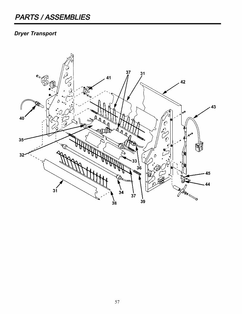
57
PPAARRTTSS // AASSSSEEMMBBLLIIEESS
Dryer Transport
40
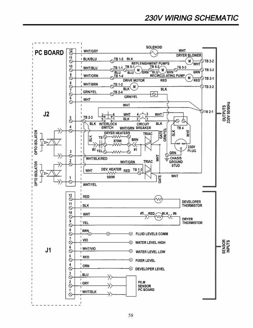
223300VV WWIIRRIINNGG SSCCHHEEMMAATTIICC
58

59
PPLLUUMMBBIINNGG SSCCHHEEMMAATTIICC