x operating manual gateway - pyrexx.com · en operating manual: px-ip - gateway 3 1 notes on the...
TRANSCRIPT

PX-iP GatewayOperating Manual
2
Operating Manual: PX-iP - Gateway EN
The original version of this instruction hasbeen prepared in German in accordancewith DIN EN 82079-1.
Table of Contents
1 Notes on the operating manual 32 Safety instructions 93 Overview 144 Commissioning and setting up 165 Reset 256 Installation variants 267 Notifications 318 Troubleshooting 349 Maintenance 4610 Decommissioning 4811 Accessories, spare parts and service 4812 Glossary 4913 Technical data 5014 Alarm and alert tones 52
EN

Operating Manual: PX-iP - Gateway 3EN
1 Notes on the operating manual
We are glad that you have chosen our product and we would like to thank you for your trust!This operating manual contains information and instructions for safe installation, com-missioning, setup and maintenance, as well as proper operation of the PX-iP gateway.The operating manual is intended to in-crease the reliability and life cycle, and to help avoid hazards and downtime, or a loss of warranty claims. It is absolutely necessary that the operating manual is read and understood.For a better readability, the PX-iP gateway is hereinafter referred to as "gateway" or "device" and the smoke alarm device with ra-dio link is referred to as "smoke alarm device".1.1 Validity of this operating manualThe operating manual only applies for the gateway.1.2 Applicable documentsThe gateway is used in combination with the manufacturer’s smoke alarm devices with radio link (e.g., PX-1C). In addition to this operating manual, also observe:
• The Quick Reference Guide provided with the device
• The operating manual for the smoke alarm device
• FAQ for the web app under the menu item "Help/FAQ"
• New features of the web app under the menu item "Help/Features"
The operating manual of the PX-iP gate-way is not provided in printed form with the device. The current version of this manual is available at:pyrexx.com/de/support/downloads

4
Operating Manual: PX-iP - Gateway EN
f If you have questions about the product or require help with the installation, please contact our product support department by telephone at +49 30 8871 606 641. You can reach our product support department on work-ing days during normal business hours.
1.3 Name plate and identificationThe name plate of the gateway can be found on the underside of the device.
Fig. 1 Name plate (sample, information can deviate)
1.4 CE conformityPyrexx GmbH declares that the PX-iP gate-way is compliant with the fundamental re-quirements and other relevant provisions of the following directives: • RED-Directive 2014/53/EU • Regulation (EC)
No 1907/2006 (REACH) • Waste Electrical and Electronic Equip-
ment Directive (disposal) 2012/19/EU • Restriction on the use of certain haz-
ardous substances in electrical and electronic equipment 2011/65/EU
The CE Declaration of Conformity is available from the manufacturer under the following reference number: k_91659
Operating Manual: PX-iP - Gateway 5EN
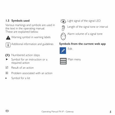
1.5 Symbols usedVarious markings and symbols are used in the text in the operating manual.These are explained below.
Warning symbol in warning labels
Additional information and guidelines
(1) Numbered action steps f Symbol for an instruction or a
required action 5 Result of an action
4 Problem associated with an action • Symbol for a list
Light signal of the signal LED
Length of the signal tone or interval
Alarm volume of a signal tone
Symbols from the current web app
Edit
Main menu
6
Operating Manual: PX-iP - Gateway EN
1.6 CopyrightAll rights are reserved, particularly the rights of duplication, distribution and translation. No par t of this operating manual may be reproduced in any form, or processed, duplicated, or disseminated using electronic systems without written permission of Pyrexx GmbH.1.7 Limited warrantyWhen used and serviced as intended, Pyrexx GmbH warrants a defect-free de-vice only for the original purchaser of this product that was purchased either from Pyrexx GmbH directly, or through an au-thorized reseller, for a period of 2 years from the date of purchase. The limited warranty is not transferable and does not apply to buyers who have purchased the device from a reseller who is not autho-rized by Pyrexx GmbH. This also applies for online auctions, but is not limited thereto. Rights arising from statutory regulations remain unaffected by the limited warranty.
f Please keep your receipt as proof that the device has been purchased from Pyrexx GmbH or from an authorized dealer, and as a proof of purchase date.
This receipt is mandatory for any warranty claims! The limited warranty will be grant-ed only if the device is used in accordance with the operating manual. The limited warranty does not cover claims resulting from accidents, misuse, application errors, negligence, or the warranty exclusion cri-teria described below.1.8 Warranty exclusion criteria
Physical / mechanical damageIf the device has been damaged, e.g., the housing has been broken or the device has been opened, any warranty claim shall be forfeited. The same shall apply to subject-ing the device to any form of force, which does not cause physical damage to the device, but does cause damage inside the housing (e.g., the electronics).
Operating Manual: PX-iP - Gateway 7EN
ContaminationIf the device is externally and / or inter-nally contaminated by adhering substances (excessively contaminated), any warranty claim shall be forfeited. Paint and similar substances on the surface of the device and within the housing of the device shall be considered as contamination.Moisture damage / corrosionIf the device, and in particular its electron-ics, are damaged by moisture of any kind, any warranty claim shall be forfeited. Thus moistureisnotonlytheexposuretofluid,but also regular, above-average exposure of the device to humidity (> 70%). Liquids and high humidity can damage the elec-tronics of the device by causing corrosion.Thermal damageIf the device has been exposed temporari-ly or continuously to a temperature below 0° C or above 70° C, any warranty claim shall be forfeited.
Excessive rechargeable battery loadThe device's rechargeable battery is used for emergency power supply (e.g., during a power failure) and it can be recharged a limited number of times. Excessive device operation via this rechargeable battery and premature consumption of the limit-ed number of charge cycles can cause any warranty claim to be forfeited.Observe with the following before sub-mitting a warranty claim:
f Check if at least one of the aforementioned warranty exclusion reasons is present.
f Bear in mind also that there are sufficienttechnicalcapabilitiestodetermine, when submitting a warranty claim, whether the device has really been used as intended, and therefore if the warranty claim is justifiedorunjustified.
8
Operating Manual: PX-iP - Gateway EN
Pyrexx GmbH expressly reserves the right to charge a person who makes a warranty claim although at least one of the afore-mentioned warranty exclusion reasons is present, for the costs associated with the necessary technical examination of the facts.1.9 DisclaimerExcept for the limited warranty described herein, Pyrexx GmbH assumes no addi-tional explicit or implicit liability under the applicable statutory provisions. This shall also extend to any liability in relation to tradeability and / or suitability for a par-ticular purpose under any implied liability which nevertheless exists under the law; the after-sales services shall be limited to the duration of this warranty.
1.10 Limitation of liabilityYour rights are limited to the repair or re-placement of this device as shipped.Pyrexx GmbH shall accept no liability for any special, incidental or consequential damages, including, but not limited to, resulting lossof revenue, lossofprofits,restrictions of the use of software /hard-ware, loss or recovery of data, cost of substitute equipment, downtime, damage to property and claims by third parties as a result of contractual, statutory or tort recovery claims arising out of warranty, regardless of any other warranty, limited or implied by the law, or in the event that the limited warranty shall not apply, the li-ability of Pyrexx GmbH shall be limited to the purchase price of the device.

Operating Manual: PX-iP - Gateway 9EN
2 Safety instructions
2.2 Intended useThe gateway is designed for the follow-ing purposes: • Communication with the
manufacturer's smoke alarm devices (e.g., PX-1C) and relaying information (e.g., smoke alarm) to the user via the Internet
• Use for smoke alarm devices in private households and small, commercially used areas with typically occurring frequency of smoke alarms
Note the following when using the gateway: f Only use the device with the power
unit and power cable provided. f Use the device only as intended
and in a technically perfect condition.
2.1 Representation and structure of warning labels
The warning labels are action-oriented; they are structured and graded as follows:
CAUTIONType and source of the risk!Explanation about the type and source.
f Measures to avert the risk.
CAUTIONPotential minor injuries, material or environmental damage.

10
Operating Manual: PX-iP - Gateway EN
2.3 Unintended useThe device must not be used for the following purposes: • Communication with smoke alarm
devices from another manufacturer • Firealarmsystemasspecified
in EN 54 and DIN 14675 • Testing of the alarm function by
intentionally triggering alarms in excess of the afore-mentioned frequencies. If there are more than 3 smoke alarms per year, thiscanblockthenotificationfunction of the gateway
• Monitoring rooms with foreseeable regular / frequently occurring smoke development
• Any use that is not expressly described as permitted in this operating manualExceptions to the above require a writ-ten agreement with the manufacturer.
2.4 General safety informationThe general safety information describesall measures to ensure safety thematicallyand applies at all times.General informationNeither the gateway nor the smoke alarm devices connected to it directly transmit analarmtoanofficialentitythatcanpro-videhelp (firebrigade).Thegateway issubject to strict quality controls during production. In addition, a function test is performed before delivery. Nevertheless, unexpected malfunctions can occur. The manufacturer is not responsible for timely forwarding of an alarm and accordingly accepts no liability if an alarm is not or forwarded or not promptly forwarded to the user (e.g., failure of the Internet connection).

Operating Manual: PX-iP - Gateway 11EN
Data securityThe device can communicate with smoke alarm devices and repor t information (e.g., smoke alarm) to the user via the Internet.Relative to data security, the manufacturer warrants the following: • Your gateway sends data via the
Internet with strong encryption and an individual key
• Personal data is treated with strict confidentialitybyPyrexxDataGmbH
• All information concerning residen-tial addresses, as well as positions of smoke alarm devices, is optional
• Forwarding of alarms to systems of third party providers is only possible if you make these settings yourself
• The web app does not process any data concerning the position of your smartphone, the gateway or the smoke alarm device
• On request, Pyrexx product support will delete your data from its IT system
Replacing the rechargeable batteryUnder some circumstances you must re-place the rechargeable battery, e.g., if the provided rechargeable battery is defective or if the charge cycles have been used up.
CAUTIONInjuries due to use of non-author-ised rechargeable batteries!Rechargeable batteries that are not authorised by the manufacturer can explode or ignite. This can result in chemical burns and other burn injuries. It can lead to limitations in the functionality and total failure of the gateway. Guarantee and warranty claims can no longer be accepted.
f Only use the rechargeable batteries specifiedbythemanufacturer (3.6 V, NiMH, AA-LSD-NTC).
f Please observe chapter 9.3 “Replacing the rechargeable battery” on page 47.
12
Operating Manual: PX-iP - Gateway EN
External influencesExternalinfluencescancausemalfunctionsand damage to the device as well as the rechargeable battery.Protect the device from: • Moisture • Cold • Direct sunlight and excessive heat
(damage to the rechargeable battery) • Dustandfinedust • Spiders and insect infestation • Grease • Nicotine and paint fumes • Paintfinishes(e.g.,wallpaint) • Adhesives • Contamination of any kind
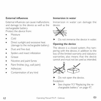
Immersion in waterImmersion in water can damage the device.
f Do not immerse the device in water.Opening the deviceThe device is a closed system. Any tam-pering with the device, in addition to the loss of the limited warranty and statutory warranties, also means that the device cannot and must not be used as intended.
f Do not open the device.Exception:
f See chapter 9.3 “Replacing the re-chargeable battery” on page 47.

Operating Manual: PX-iP - Gateway 13EN
Sensitive componentsThe device consists of sensitivecomponents.
f Do not throw the device. f Do not let the device fall. f Do not exert any pressure on the
device.
14
Operating Manual: PX-iP - Gateway EN
3 Overview
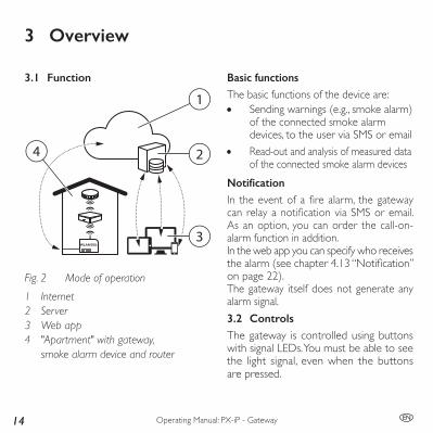
Basic functionsThe basic functions of the device are: • Sending warnings (e.g., smoke alarm)
of the connected smoke alarm devices, to the user via SMS or email
• Read-out and analysis of measured data of the connected smoke alarm devices
NotificationIn theeventofafirealarm, thegatewaycan relayanotificationviaSMSoremail. As an option, you can order the call-on-alarm function in addition.In the web app you can specify who receives thealarm(seechapter4.13“Notification”on page 22).The gateway itself does not generate any alarm signal.3.2 ControlsThe gateway is controlled using buttons with signal LEDs. You must be able to see the light signal, even when the buttons are pressed.
3.1 Function
Fig. 2
1
2
3
4
Mode of operation
1 Internet2 Server3 Web app4 "Apartment" with gateway,
smoke alarm device and router
Operating Manual: PX-iP - Gateway 15EN
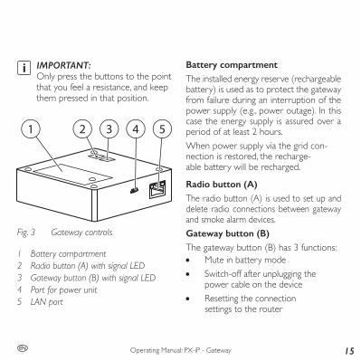
IMPORTANT: Only press the buttons to the point that you feel a resistance, and keep them pressed in that position.
2 3 4 51
Fig. 3 Gateway controls
1 Battery compartment2 Radio button (A) with signal LED3 Gateway button (B) with signal LED4 Port for power unit5 LAN port
Battery compartmentThe installed energy reserve (rechargeable battery) is used as to protect the gateway from failure during an interruption of the power supply (e.g., power outage). In this case the energy supply is assured over a period of at least 2 hours.When power supply via the grid con-nection is restored, the recharge-able battery will be recharged.
Radio button (A)The radio button (A) is used to set up and delete radio connections between gateway and smoke alarm devices.Gateway button (B)The gateway button (B) has 3 functions: • Mute in battery mode • Switch-off after unplugging the
power cable on the device • Resetting the connection
settings to the router

16
Operating Manual: PX-iP - Gateway EN
Signal LEDsThe signal LEDs in the radio button (A) and gateway button (B) show status messages (e.g., at commissioning and set-up).Connection for the power unitThe mains connection is used for the energy supply of the gateway via pow-er unit and power cable. By plugging in and unplugging the power cable on the device, you switch the gateway on or off (see chapter 4.16 “Switching off the gate-way” on page 24).
By unplugging the power unit from electrical outlet, you bring the gateway into battery operation.
LAN portThe LAN port connects the gateway to the router via the LAN cable. It is strictly required for the installation.
4 Commissioning and setting up
The operating manual describes initial in-stallation of the gateway in combination with smoke alarm devices when using the web app.
f It is essential that you follow the actionstepsinthespecifiedorderfor successful installation.
f For other types of installation, e.g. installing the gateway in an existing radio group, see chapter 6 “Installa-tion variants” on page 26.
f Observe the notes in the web app. f Only use the power unit and power
cable supplied with the device. f Removetheprotectivefilmfrom
the power unit and the gateway.4.1 Requirements for commissioningPrior to commissioning, ensure the follow-ing at the installation location: • Internet connection • Router with LAN port • LAN or WI-FI connection

Operating Manual: PX-iP - Gateway 17EN
• For WI-FI: WLAN-SSID (WI-FI name), password and encryption type must be known
• At least one PX-1C smoke alarm device • Gateway in default state
(see chapter 5.1 “Gateway reset” on page 25)
• End device for web app operation: smartphone, tablet or PC with Internet browser
4.2 Open the web app
f Open the web app in the browser at pyrexx.com/app.
4.3 Register as a userIf you do not already have access to the webapp,setupyouruseraccountfirst:(1) In the web app’s start-up screen,
click “Register”.(2) Enter your email address and
choose a password.The email address will be your user name.
(3) Check the “I accept the Terms and Conditions” check box.
(4) Click “Complete registration”. 5 Registration successful.
4.4 Log-in
(1) On the start-up screen, enter your user name (email) and password.
(2) Click “Log in”. 5 Web app log-in successful.
5 Empty device list appears.
4.5 Adding a gateway (web app)
(1) Click on “add a device”.(2) Assign the gateway to a room.(3) Enter the serial number on the
name plate of your gateway. 5 “Gateway” is shown as the type and
“Pyrexx” as the manufacturer.(4) Entertheverificationcodeonthe
name plate of your gateway.
18
Operating Manual: PX-iP - Gateway EN
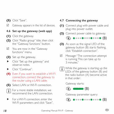
(5) Click “Save”. 5 Gateway appears in the list of devices.
4.6 Set up the gateway (web app)
(1) Click the gateway.(2) Click “Radio group” title, then click
the “Gateway functions” button. 5 You are now in the “Gateway
functions” menu.(3) Set up the gateway.
f Click “Set up the gateway” and observe notes.
f Click “Continue”.(4) Even if you want to establish a WI-FI
connection, connect the gateway to the router using a LAN cable.
(5) Select LAN or WI-FI connection.For a more stable installation, we recommend the LAN connection.
f For a WI-FI connection, enter the WI-FI parameters and click “Save”.
4.7 Connecting the gateway
(1) Connect plug with power cable and plug into power outlet.
(2) Connect power cable to gateway.(B)
(3) As soon as the signal LED of the gatewaybutton(B)startsflashing,click “Establish connection”.
5 Message: “The connection attempt is running. This can take up to 3 minutes.”
While the gateway is starting up the LEDs of the gateway button (B) and the radio button (A) become active in that order:
Gateway starts:
(B)Gateway parameter query:
(B)
Operating Manual: PX-iP - Gateway 19EN
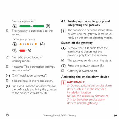
Normal operation:(B)
5 The gateway is connected to the server.Radio group query:
(A)
(A)
5 No radio group found in learning mode.
5 Message: “The connection attempt was successful”
(4) Click “Installation complete”. 5 You are now in the room sketch.
(5) For a WI-FI connection, now remove the LAN cable and bring the gateway to the planned installation site.
4.8 Setting up the radio group and integrating the gateway
The connection between smoke alarm devices and the gateway is set up di-rectly on the devices (learning mode).
Switch off the gateway
(1) Remove the USB cable from the gateway and disconnect the power supply from the gateway.
5 The gateway sends a warning signal.(2) Press the gateway button (B).
5 Gateway is switched off.
Activating the smoke alarm device
IMPORTANT:a) Do not activate any smoke alarm device until it is at the intended installation location.b) Ensure a minimum distance of 3 m to the other smoke alarm devices and the gateway.

20
Operating Manual: PX-iP - Gateway EN
(1) Remove splint pin on the red activa-tion button of the smoke alarm device.
(2) Pushactivationbuttonflush.Short acoustic signal
Radio group query:
(3) Press the radio button on the smoke alarm device with the splint pin (activation backup) until the signal LED begins to light up, then release it.Starting the learning mode on the smoke alarm device:
5 Radio group is in learning mode for 10 minutes.
(4) Add further smoke alarm devices one after another to the radio group. To do this, press in the activation buttons on the respective smoke alarmdevicessothattheyareflush.With every newly added device to the radio group, the learning mode dura-tion resets to a further 10 minutes.
Integrating the gatewayAfter you have activated the desired num-ber of smoke alarm devices (max. 14), you need to integrate the gateway into the radio group:(1) Connect the USB cable to the gate-
way and restore the power supply to the gateway.While the gateway is starting up the LEDs of the gateway button (B) and the radio button (A) become active in that order:Gateway starts:
(B)
Operating Manual: PX-iP - Gateway 21EN
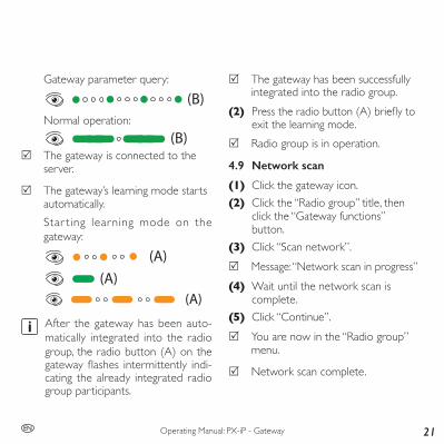
Gateway parameter query:
(B)Normal operation:
(B) 5 The gateway is connected to the
server.
5 The gateway’s learning mode starts automatically.Star ting learning mode on the gateway:
(A)(A)
(A)
After the gateway has been auto-matically integrated into the radio group, the radio button (A) on the gatewayflashes intermittently indi-cating the already integrated radio group participants.
5 The gateway has been successfully integrated into the radio group.
(2) Presstheradiobutton(A)brieflytoexit the learning mode.
5 Radio group is in operation.
4.9 Network scan
(1) Click the gateway icon.(2) Click the “Radio group” title, then
click the “Gateway functions” button.
(3) Click “Scan network”. 5 Message: “Network scan in progress”
(4) Wait until the network scan is complete.
(5) Click “Continue”. 5 You are now in the “Radio group”
menu.
5 Network scan complete.

22
Operating Manual: PX-iP - Gateway EN
4.10 Assigning smoke alarm devices to rooms
f In the drop-down menu of each smoke alarm device, assign it to the corresponding room.
IMPORTANT: The 13-digit serial number of the device can be found under the cover of the smoke alarm device.
5 The smoke alarm devices have been assigned to the rooms.
4.11 Test signal
(1) Click the “Radio group” title, then click the “Gateway functions” button.
(2) Click “Trigger test signal”. 5 Message: “Test signal in progress”
Short acoustic signal from all installed smoke alarm devices
4.12 Measured data
(1) To view the measured data of a smoke alarm device, click the smoke alarm device in the “Radio group”menu.
(2) Click the “Maintenance” title, then click the “Measured data” button.
5 Measured data of the smoke alarm device is displayed.
4.13 NotificationFor the following events the web app sends notificationstotheuserviaemailorSMS: • Smoke alarm:
In addition to the email, an SMS can also be sent
• Malfunction (see chapter 8 “Troubleshooting” on page 34)
• Test requirement for smoke alarm devices and maintenance reminder
Allnotificationsarealwayssenttotheuserwho created the apartment in the web app. The email address and mobile telephone number can be changed in the web app.
Operating Manual: PX-iP - Gateway 23EN
To do so, proceed as follows:
(1) Click .(2) Select "Settings".(3) Click "User information" and in the
drop-down menu, select either "Alerting (Telephone)" or "Alerting (E-Mail)".
(4) Click "Add mobile phone number" or "Add email address" and enter the desired email addresses or mobile phone numbers.Please note that mobile phone num-bers must begin with an international area code (e.g. 0049).
5 All of the stored recipients will be informed in case of an alarm.
4.14 GSM alarming
If there is a connection fault to the router, the gateway can send a smoke alarm, as long as GSM recep-tion is available. This is established through a permanently installed SIM card from the manufacturer.
Check GSM reception at the gateway location, toensurerelayofnotificationseven if the WI-FI or LAN connection is interrupted. Proceed as follows:(1) With a smartphone, check whether
GSM reception exists at the installa-tion site of the gateway.
(2) Change the location of the gateway if necessary.

24
Operating Manual: PX-iP - Gateway EN
4.16 Switching off the gatewayTo switch off the gateway without re-setting the gateway or the radio settings, proceed as follows:(1) Remove the power cable from the
gateway.
Cyclic acoustic signal on the gateway for 30 seconds
(2) Wait 30 seconds.or(3) Brieflypressgatewaybutton(B).
5 Gateway is switched off.
5 With a delay of 10 minutes you will get the message "Connection to PX-iP lost".When it is switched off, no alarms will be forwarded, not even via GSM.
When you reconnect the power cable, the gateway is placed in service again. You will receive an email stating "Gateway is again reachable".
4.15 Call-on-alarm
Ifthereisasmokealarm,thefirstmobiletelephonenumberspecifiedwillbecalledand the participant informed with an au-tomatic announcement.To book the "Call-on-alarm" function, pro-ceed as follows:(1) Open the web app in the browser
at pyrexx.com/app.(2) Click on the "Shop" menu item and
select "Call-on-alarm".(3) Book the "Call-on-alarm" function
for 12 or 24 months. 5 The call will be forwarded in case
of an alarm.
Operating Manual: PX-iP - Gateway 25EN
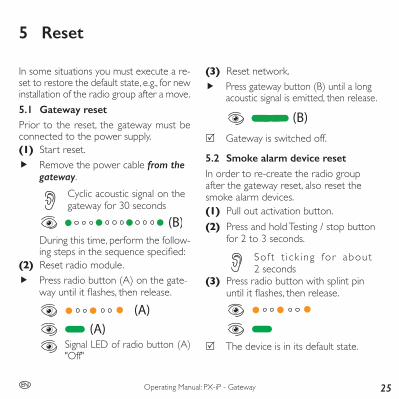
5 Reset
(3) Reset network. f Press gateway button (B) until a long
acoustic signal is emitted, then release.
(B) 5 Gateway is switched off.
5.2 Smoke alarm device resetIn order to re-create the radio group after the gateway reset, also reset the smoke alarm devices. (1) Pull out activation button.(2) Press and hold Testing / stop button
for 2 to 3 seconds.
So f t t i ck ing for about 2 seconds
(3) Press radio button with splint pin until itflashes,thenrelease.
5 The device is in its default state.
In some situations you must execute a re-set to restore the default state, e.g., for new installation of the radio group after a move.5.1 Gateway resetPrior to the reset, the gateway must be connected to the power supply.(1) Start reset.
f Remove the power cable from the gateway.
Cyclic acoustic signal on the gateway for 30 seconds
(B)During this time, perform the follow-ingstepsinthesequencespecified:
(2) Reset radio module. f Press radio button (A) on the gate-wayuntilitflashes,thenrelease.
(A)(A)
Signal LED of radio button (A) "Off"

26
Operating Manual: PX-iP - Gateway EN
5 The learning mode is active for 10 minutes, the signal LEDs on all installed members of the radio groupareflashing.
(2) Adding additional smoke alarm devices.
f Remove splint pin on the red acti-vation button of the smoke alarm device.
f Press the activation button so that it is flush.
Short acoustic signal
Radio group query:
f Add further smoke alarm devices one after another to the radio group. To do this, press in the activation but-tons on the respective smoke alarm devicessothattheyareflush.
6 Installation variants
6.1 New installation
f Perform a new installation in accor-dance with chapter 4.8 “Setting up the radio group and integrating the gateway” on page 19.
6.2 Adding a smoke alarm device to a radio group
(1) Press the radio button (A) on the gateway or on any of the PX-1C devices until the signal LED lights up and hold until it goes out, and then release.
(A)Starting the learning mode on the gateway or on one of the smoke alarm devices:
(A)(A)
(A)
Operating Manual: PX-iP - Gateway 27EN
With every newly added device to the radio group, the learning mode duration resets to a further 10 minutes.
f To terminate the learning mode, brieflypresstheradiobuttononthe gateway or smoke alarm device.
5 The smoke alarm device has been successfully integrated into the radio group.
5 The changes get visible when you perform a network scan in the web app.
28
Operating Manual: PX-iP - Gateway EN
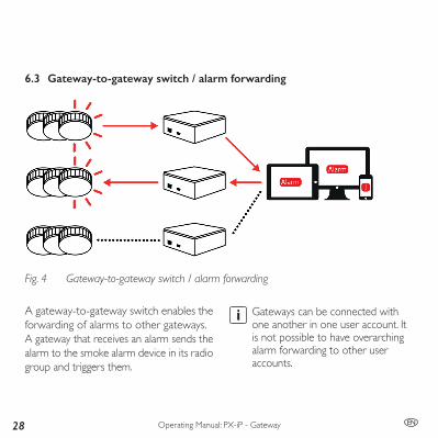
Gateways can be connected with one another in one user account. It is not possible to have overarching alarm forwarding to other user accounts.
6.3 Gateway-to-gateway switch / alarm forwarding
Fig. 4 Gateway-to-gateway switch / alarm forwarding
A gateway-to-gateway switch enables the forwarding of alarms to other gateways.A gateway that receives an alarm sends the alarm to the smoke alarm device in its radio group and triggers them.
Operating Manual: PX-iP - Gateway 29EN
The settings for the gateway-to-gateway switch are made directly in the web app, so that it is not necessary to perform any manual actions on the device.There are several options for gate-way-to-gateway switching in the web app.Selected functions always refer to the gateway on which the functions are activated.Incoming alarms
Alarms are received by the gateway and only trigger the smoke alarm devices of the (shared) radio group.Outgoing alarms
Alarms are sent to other gateways, these react differently according to their settings.
Residential buildingsIn residential buildings, the alarms are only forwarded within an apartment that has been created.You can choose from the following options: • No forwarding • Outgoing and incoming • Only outgoing • Only incoming • Outgoing / incoming in the
residential building • Incoming in the residential building
6.4 Large dwelling unitsThe web app creates 6 typical living areas for each new apartment. For large dwell-ing units (e.g., kindergartens, dormitories) we recommend adding all rooms in the web app beforehand.
30
Operating Manual: PX-iP - Gateway EN
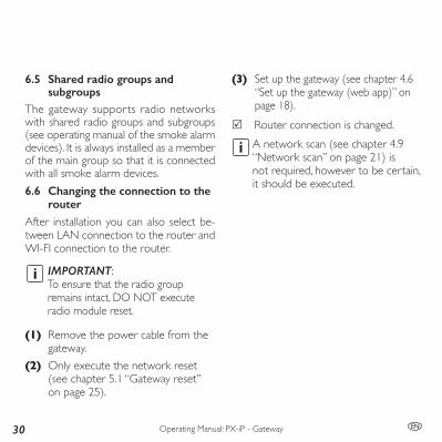
6.5 Shared radio groups and subgroups
The gateway supports radio networks with shared radio groups and subgroups (see operating manual of the smoke alarm devices). It is always installed as a member of the main group so that it is connected with all smoke alarm devices.6.6 Changing the connection to the
routerAfter installation you can also select be-tween LAN connection to the router and WI-FI connection to the router.
IMPORTANT:To ensure that the radio group remains intact, DO NOT execute radio module reset.
(1) Remove the power cable from the gateway.
(2) Only execute the network reset (see chapter 5.1 “Gateway reset” on page 25).
(3) Set up the gateway (see chapter 4.6 “Set up the gateway (web app)” on page 18).
5 Router connection is changed.A network scan (see chapter 4.9 “Network scan” on page 21) is not required, however to be certain, it should be executed.
Operating Manual: PX-iP - Gateway 31EN
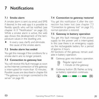
7.4 Connection to gateway restoredYouget thisnotification if, after thecon-nection has been lost (see chapter 7.3 “Connection to gateway lost” on page 31), normal operation is restored.7.5 Gateway in battery operationYou get this fault message if the power supply to the power unit is interrupted. In this case there is an emergency supply via the rechargeable battery for a period of approx. 2 hours. All functions of the gateway remain avail-able in battery operation.
4 Gateway goes into battery operation.Regular signal over 1 minute on the gateway
4 Gatewaybutton(B)flashesaslongas battery operation continues.
(B)
7 Notifications
7.1 Smoke alarmA smoke alarm is sent via email, and SMS if desired. In the web app it is possible to flexiblyspecifywhowillbenotified(seechapter4.13“Notification”onpage22).While a smoke alarm is active, the web app shows the development of the tem-perature values in the dwelling unit.
f In every case, clarify and eliminate the cause of the smoke alarm.
7.2 Smoke alarm has endedYou get this message if the conditions for a smoke alarm are no longer present.7.3 Connection to gateway lostYou will receive this fault message as soon as the Internet connection of the gateway is interrupted for more than 10 minutes.Possible causes are described in chapter 8.6 “The gateway is no longer connected to the server” on page 40.

32
Operating Manual: PX-iP - Gateway EN
7.7 Connection to smoke alarm device lost
Connection problems to smoke alarm devices are detected with the aid of a network scan (see chapter 4.9 “Network scan” on page 21).
4 If the connection to a smoke alarm device is interrupted, you will get an email within the automatic test interval.
Possible causes: • Installation location of an
existing smoke alarm device has been changed
• Smoke alarm devices that have been added have been mounted too far away from, or too close to existing smoke alarm devices
• The initial installation was faulty, this is particularly possible for installations without a gateway
Possible causes: • Gateway power plug unplugged • Power outage • Power unit or cable defective
Remedy: f Restore the power supply within
2 hours or replace the rechargeable battery (see chapter 9.3 “Replacing the rechargeable battery” on page 47).
f Replace power unit or cable if necessary.
7.6 Gateway in network operation again
Youreceivethisnotificationif,afterbatteryoperation (see chapter 7.5 “Gateway in battery operation” on page 31) of the gateway, the power supply is restored.

Operating Manual: PX-iP - Gateway 33EN
• Other sources of radio interference impair the radio communication
• Smoke alarm devices are defective or switched off
Remedy: f See chapter 8.7 “Error in the radio
connection (smoke alarm device reachability)” on page 43.
7.8 Maintenance reminderWhen the last maintenance of the smoke alarm device of an apartment is 11 months in the past, a reminder is sent to the person who created the dwelling unit. This message will be repeated month-ly until the executed maintenance has been documented in the web app.
7.9 Status of the smoke alarm devices
Within the automatic test interval the gateway reads out the status of the smoke alarm devices. The result is sent per email to the user of the web app.This status message alerts the user when at least one of the smoke alarm devices provides measured data that soon there-after will result in acoustic fault messages (battery status, contamination).Regardless of the above, the reminder message concerning the maintenance oc-curs in accordance with DIN 14676.

34
Operating Manual: PX-iP - Gateway EN
8 Troubleshooting
Remedy: f Place the gateway in service again
and pay attention to the sequence of installation steps (see chapter 4 “Commissioning and setting up” on page 16).
8.2 Error when adding the gateway
4 Gateway cannot be created in the web app.
Possible causes:Invalid serial number or verification code
• Serialnumberorverificationcode entered incorrectly
Remedy: f Check entry and correct if
necessary.Gateway of another manufacturer
• Serial number belongs to a gateway from another manufacturer
Problems during commissioning and set-up are indicated by error messages in the web app and LED signals on the devices.Faults during operation are communi-cated through appropr iate messages (seechapter7“Notifications”onpage31).8.1 Commissioning in the wrong
sequence
4 Gateway cannot connect to the Internet.
4 Network scan cannot be executed.
4 Maintenance data cannot be read out.Possible causes: • Gateway was not added
firstinthewebapp • The prerequisite for network scan is
that the gateway must be correctly connected
• Maintenance data will only be read out if a network scan was executed beforehand
Operating Manual: PX-iP - Gateway 35EN
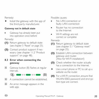
Remedy: f Install the gateway with the app of
the third-party manufacturer.Gateway not in default state
• Gateway has already been put into operation once before
Remedy:(1) Return gateway to default state
(see chapter 5 “Reset” on page 25).(2) Contact product support if nec-
essary (see chapter 11.2 “Product support” on page 48).
8.3 Error when connecting the gateway
4 Gatewaybutton(B)flashesatregularintervals.
(B) 4 A connection cannot be established.
4 An error message appears in the web app.
Possible causes: • No LAN connection or
faulty LAN connection • Router has no connection
to the Internet • WI-FI settings are not
correct or completeRemedy:(1) Return gateway to default state
(see chapter 5.1 “Gateway reset” on page 25).
(2) Establish LAN connection between gateway and router. (Also for WI-FI installation!)
(3) Check whether the router actually has a connection to the Internet.
f Use a smart phone or PC to call up a website via the router.
(4) For a WI-FI connection, ensure that WLAN-SSID, password and encryp-tion type are correct.
36
Operating Manual: PX-iP - Gateway EN
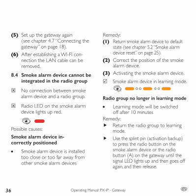
Remedy:(1) Return smoke alarm device to default
state (see chapter 5.2 “Smoke alarm device reset” on page 25).
(2) Correct the position of the smoke alarm device.
(3) Activating the smoke alarm device. 5 Smoke alarm device in learning mode.
Radio group no longer in learning mode
• Learning mode will be switched off after 10 minutes
Remedy: f Return the radio group to learning
mode. f Use the splint pin (activation backup)
to press the radio button on the smoke alarm device or the radio button (A) on the gateway until the signal LED lights up and then goes off again, and then release.
(5) Set up the gateway again (see chapter 4.7 “Connecting the gateway” on page 18).
(6) After establishing a WI-FI con-nection the LAN cable can be removed.
8.4 Smoke alarm device cannot be integrated in the radio group
4 No connection between smoke alarm device and a radio group.
4 Radio LED on the smoke alarm device lights up red.
Possible causes:Smoke alarm device in-correctly positioned
• Smoke alarm device is installed too close or too far away from other smoke alarm devices

Operating Manual: PX-iP - Gateway 37EN
5 Smoke alarm device in learning mode.
5 Gateway in learning mode.(A)
Maximum number of smoke alarm devices
• Radio group already contains the maximum number of smoke alarm devices (max. 15)
Remedy: f Reinstall radio group with a lower
number of smoke alarm devices.Smoke alarm device not in default state
• A reset was not executed on the smoke alarm device prior to activation
4 Radio LED on the smoke alarm devicebrieflylightsupgreen.
Remedy:(1) Reset of the smoke alarm device
in question (see chapter 5.2 “Smoke alarm device reset” on page 25).
(2) Reactive smoke alarm device.Smoke alarm device from an-other manufacturer
• Smoke alarm device is an identical type from a different manufacturer
Remedy: f Ensure that the manufacturer on
the name plate is identical for all devices of the radio group.
Smoke alarm device is defectiveRemedy:(1) Check whether a different smoke
alarm device in the same position changes to learning mode.
(2) Replace defective smoke alarm device.

38
Operating Manual: PX-iP - Gateway EN
(3) Install a new smoke alarm device (see chapter 6.2 “Adding a smoke alarm de-vice to a radio group” on page 26).Please also notice the detailed steps in the operating manual for the smoke alarm device.
8.5 Gateway cannot be integrated in the radio group
4 No connection between gateway and an existing radio group.
4 Radio button (A) is illuminated red.
(A)Possible causes:Gateway is incorrectly positioned
• Gateway is installed too close or too far away from other smoke alarm devices
Remedy:(1) Reset the radio module on the gate-
way (see chapter 5.1 “Gateway reset” on page 25, step 2).
(2) Correct the position of the gateway.(3) Reconnect the gateway, with power.Radio group no longer in learning mode
• Learning mode will be switched off after 10 minutes
Remedy: f Return the radio group to learning
mode. f Use the splint pin (activation backup)
to press the radio button on the smoke alarm device or the radio button (A) on the gateway until the signal LED lights up and then goes off again, and then release.
5 Smoke alarm device in learning mode.
5 Gateway in learning mode.(A)

Operating Manual: PX-iP - Gateway 39EN
Maximum number of smoke alarm devices
• Radio group already contains the max-imum number of smoke alarm devices
Remedy: f Reinstall radio group with a lower num-
ber of smoke alarm devices.Gateway not in default state
• Radio module in gateway was not in default state
4 Radiobutton(A)isbrieflyilluminat-ed green.
(A)Remedy:(1) Execute reset of the radio module
in the gateway.(2) Reset the radio module on the
gateway (see chapter 5.1 “Gateway reset” on page 25, step 2).
(3) Connect the USB cable to the gate-way and restore the power supply to the gateway.
When the gateway starts up, the LEDs for the gateway button (B) and the radio button (A) become consecutively active:Gateway starts:
(B)Gateway parameter query:
(B)Normal operation:
(B) 5 The gateway is connected to
the server.
5 The gateway's learning mode starts automatically.
Gateway is defectiveRemedy:(1) If the previously mentioned measures
do not work, contact product support (see chapter 11.2 “Product support” on page 48).
40
Operating Manual: PX-iP - Gateway EN
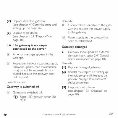
(2) Replace defective gateway (see chapter 4 “Commissioning and setting up” on page 16).
(3) Dispose of old device (see chapter 10.1 “Disposal” on page 48).
8.6 The gateway is no longer connected to the server
4 An error message appears in the web app.
4 Procedure (network scan, test signal, firmwareupdate,readmaintenancedata) cannot be successfully con-cluded, because the gateway does not respond.
Possible causes:Gateway is switched off
4 Gateway is switched off.Signal LED gateway button (B) "Off"
Remedy: f Connect the USB cable to the gate-
way and restore the power supply to the gateway.
5 Power supply to the gateway has been re-established.
Gateway damaged
• Gateway shows possible external damage (see chapter 2.4 “General safety information” on page 10)
Remedy:(1) Replace damaged gateway.(2) Reinstall the chapter 4.8 “Setting up
the radio group and integrating the gateway” on page 19 replacement device accordingly.
(3) Dispose of old device (see chapter 10.1 “Disposal” on page 48).

Operating Manual: PX-iP - Gateway 41EN
Gateway without grid power
4 Gateway is switched off.Signal LED gateway button (B) "Off"
• Power outage • Network power plug is unplugged
and no emergency reserve (rechargeable battery of the gateway is dead or defective)
Remedy: f Connect the USB cable to the gate-
way and restore the power supply to the gateway.
f Replace rechargeable battery if nec-essary (see chapter 9.3 “Replacing the rechargeable battery” on page 47).
5 Power supply to the gateway has been re-established.
Connection failure in the gateway network
4 Gatewaybutton(B)flashesatregular intervals.
(B) • Internet outage • Router defective or
without grid powerRemedy:(1) With other devices, check whether
an Internet connection exists. f Inform Internet provider if necessary.
(2) Check Internet connection of the router.
(3) Restore power supply.(4) Restart router.
f Replace router if necessary.
42
Operating Manual: PX-iP - Gateway EN
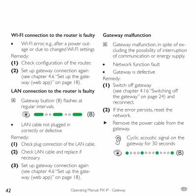
WI-FI connection to the router is faulty
• WI-FI error, e.g., after a power out-age or due to changed WI-FI settings
Remedy:(1) Checkconfigurationoftherouter.(2) Set up gateway connection again
(see chapter 4.6 “Set up the gate-way (web app)” on page 18).
LAN connection to the router is faulty
4 Gatewaybutton(B)flashesatregular intervals.
(B) • LAN cable not plugged in
correctly or defectiveRemedy:(1) Check plug connection of the LAN cable.(2) Check LAN cable and replace if
necessary.(3) Set up gateway connection again
(see chapter 4.6 “Set up the gate-way (web app)” on page 18).
Gateway malfunction
4 Gateway malfunction, in spite of ex-cluding the possibility of interruption of communication or energy supply.
• Network function fault • Gateway is defective
Remedy:(1) Switch off gateway
(see chapter 4.16 “Switching off the gateway” on page 24) and reconnect.
(2) If the error persists, reset the network.
f Remove the power cable from the gateway.
Cyclic acoustic signal on the gateway for 30 seconds
(B)
Operating Manual: PX-iP - Gateway 43EN
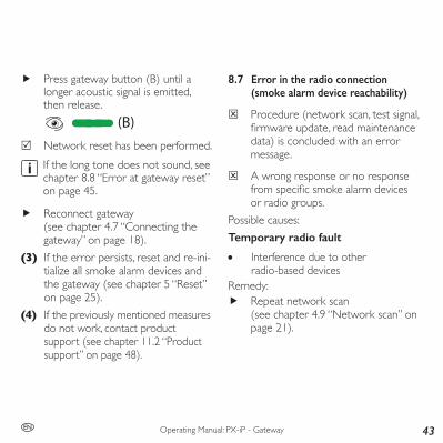
f Press gateway button (B) until a longer acoustic signal is emitted, then release.
(B) 5 Network reset has been performed.
If the long tone does not sound, see chapter 8.8 “Error at gateway reset” on page 45.
f Reconnect gateway (see chapter 4.7 “Connecting the gateway” on page 18).
(3) If the error persists, reset and re-ini-tialize all smoke alarm devices and the gateway (see chapter 5 “Reset” on page 25).
(4) If the previously mentioned measures do not work, contact product support (see chapter 11.2 “Product support” on page 48).
8.7 Error in the radio connection (smoke alarm device reachability)
4 Procedure (network scan, test signal, firmwareupdate,readmaintenancedata) is concluded with an error message.
4 A wrong response or no response fromspecificsmokealarmdevicesor radio groups.
Possible causes:Temporary radio fault
• Interference due to other radio-based devices
Remedy: f Repeat network scan
(see chapter 4.9 “Network scan” on page 21).
44
Operating Manual: PX-iP - Gateway EN
(3) Dispose of old device (see chapter 10.1 “Disposal” on page 48).
Not with the smoke alarm device connected to the radio group
• A smoke alarm device has indeed been installed but not integrated in the radio group
Remedy:(1) Put the radio group into learning
mode and add smoke alarm devices (see chapter 6.2 “Adding a smoke alarm device to a radio group” on page 26).
(2) Repeat network scan (see chapter 4.9 “Network scan” on page 21).
Smoke alarm device switched offRemedy:(1) Switch on the smoke alarm device
(see operating manual for the smoke alarm devices).
(2) Repeat network scan (see chapter 4.9 “Network scan” on page 21).
Smoke alarm device is defectiveRemedy:(1) Procure a replacement device.(2) Bring the radio group into learning
mode and add replacement device (see chapter 6.2 “Adding a smoke alarm device to a radio group” on page 26).
or(1) Reset and set-up the radio group
again with replacement device.(2) Repeat network scan
(see chapter 4.9 “Network scan” on page 21).
Operating Manual: PX-iP - Gateway 45EN
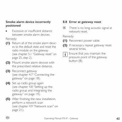
8.8 Error at gateway reset
4 There is no long acoustic signal at network reset.
Remedy:(1) Reconnect power cable.(2) If necessary repeat gateway reset
several times.Ensure that you maintain the pressure point of the gateway button (B).
Smoke alarm device incorrectly positioned
• Excessiveorinsufficientdistancebetween smoke alarm devices
Remedy:(1) Return all of the smoke alarm devic-
es to the default state and reset the radio module on the gateway (see chapter 5.1 “Gateway reset” on page 25, step 2).
(2) Mount smoke alarm devices with the prescribed relative distance.
(3) Reconnect gateway (see chapter 4.7 “Connecting the gateway” on page 18).
(4) Set up radio group again (see chapter 4.8 “Setting up the radio group and integrating the gateway” on page 19).
(5) Afterfinishingthenewinstallation,perform a network scan (see chapter 4.9 “Network scan” on page 21).
46
Operating Manual: PX-iP - Gateway EN
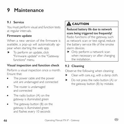
9 Maintenance
9.1 ServiceYou must perform visual and function tests at regular intervals.Firmware updateWhenanewversionofthefirmware isavailable, a pop-up will automatically ap-pear when starting the web app.
f To perform an update, click "Firmware update" in the "Gateway functions" menu.
Visual inspection and function checkPerform a visual inspection once a month. Ensure that: • The power cable and the power
unit are undamaged and connected • The router is undamaged
and connected • The radio button (A) on the
gateway is illuminated green • The gateway button (B) on the
gateway is illuminated green andflashesevery10seconds
CAUTIONReduced battery life due to network scans being triggered too frequently!Radio functions of the gateway, such as network scan or test signal, reduce the battery service life of the smoke alarm devices.
f Only perform a network scan when necessary or after changing the installation.
9.2 CleaningObserve the following when cleaning:
f Clean with care, e.g., with a damp cloth. f Do not press the radio button (A) or
the gateway button (B) by mistake.
Operating Manual: PX-iP - Gateway 47EN
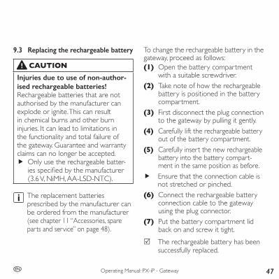
9.3 Replacing the rechargeable battery
CAUTIONInjuries due to use of non-author-ised rechargeable batteries!Rechargeable batteries that are not authorised by the manufacturer can explode or ignite. This can result in chemical burns and other burn injuries. It can lead to limitations in the functionality and total failure of the gateway. Guarantee and warranty claims can no longer be accepted.
f Only use the rechargeable batter-iesspecifiedbythemanufacturer (3.6 V, NiMH, AA-LSD-NTC).
The replacement batteries prescribed by the manufacturer can be ordered from the manufacturer (see chapter 11 “Accessories, spare parts and service” on page 48).
To change the rechargeable battery in the gateway, proceed as follows:(1) Open the battery compartment
with a suitable screwdriver.(2) Take note of how the rechargeable
battery is positioned in the battery compartment.
(3) First disconnect the plug connection to the gateway by pulling it gently.
(4) Carefully lift the rechargeable battery out of the battery compartment.
(5) Carefully insert the new rechargeable battery into the battery compart-ment in the same position as before.
f Ensure that the connection cable is not stretched or pinched.
(6) Connect the rechargeable battery connection cable to the gateway using the plug connector.
(7) Put the battery compartment lid back on and screw it tight.
5 The rechargeable battery has been successfully replaced.
48
Operating Manual: PX-iP - Gateway EN
11 Accessories, spare parts and service
10 Decommissioning
10.1 DisposalThis product should never be placed in domestic waste according to the German Electrical and Electronic Devices Act (ElektroG).
f Return the device to be disposed of to the manufacturer for further utilization, or hand it over to your local waste disposal company.
f Note that improper dispos-al can harm the environment.
11.1 Accessories and spare parts
• Power cable • Power unit • Spare rechargeable battery for gateway
(can be purchased from the manufacturer)
• Smoke alarm device with radio link PX-1C
11.2 Product supportPyrexx GmbHSiemensdamm 6213627 BerlinGermany
+49 30 74 74 74 75
To reach our product support please con-tact [email protected] or use the con-tact form in the web app.Youcanfindexplanatoryvideosaboutourproducts at pyrexx.com/en/support/media.

Operating Manual: PX-iP - Gateway 49EN
12 Glossary
Radio networkThe total number of shared radio groups and subgroups in the connection with a gateway.Learning modeThe learning mode is the state in which it is possible to add new devices into an existing radio group.Network scanThe network scan scans all members of a radio network and allocates the devices to the gateway. In this process, it queries the measured data of the connected smoke alarm device: • Temperature • Contamination • Battery level • Signal level
The measured data are regularly and au-tomatically updated after the network scan.
50
Operating Manual: PX-iP - Gateway EN
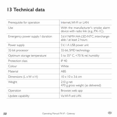
13 Technical data
Prerequisite for operation Internet, WI-FI or LANUse With the manufacturer's smoke alarm
device with radio link (e.g., PX-1C).Emergency power supply / duration 3.6 V NiMH AA-LSD-NTC, interchange-
able / at least 2 hoursPower supply 5 V, 1 A USB power unit32-bit processor 32-bit, SMD technologyOptimum storage temperature 5 to 35° C, <70 % rel. humidityProtection class IP 40Colour WhiteMaterial ABSDimensions (L x W x H) 10 x 10 x 3.6 cmWeight 210 g net
470 g gross weight (as delivered)Operation Browser, web appUpdate capability Via WI-FI and LAN
Operating Manual: PX-iP - Gateway 51EN
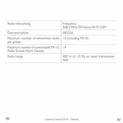
Radio networking Frequency:868.3 MHz, ISM-band, WI-FI, GSM
Data encryption AES256Maximum number of networked nodes per group:
15 (including PX-iP)
Maximum number of connectable PX-1C Radio Smoke Alarm Devices
14
Radio range 400 m (± 10 %) on open transmission field
52
Operating Manual: PX-iP - Gateway EN
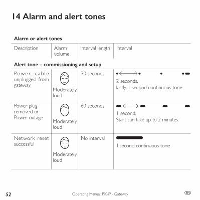
14 Alarm and alert tones
Alarm or alert tones
Description Alarm volume
Interval length Interval
Alert tone – commissioning and setup
Po w e r c a b l e unplugged from gateway
/ 30 seconds
Power plugremoved or Power outage
60 seconds
Network reset successful
No interval/
2 seconds,lastly, 1 second continuous tone
1 second,Start can take up to 2 minutes.
Moderately loud
1 second continuous tone
Moderately loud
Moderately loud


© Pyrexx GmbHk_263363
Revision of the brochure 2018-09, Subject to change
Legal noticePyrexx GmbHSiemensdamm 6213627 BerlinGermany