x-en ct 3000 installation n1-1 - leesan marine … installing the toilet 4.0installing the toilet...
TRANSCRIPT
242 6011-64en
T.B. MBA 01/2008
English
N 1-1
INSTALLATION INSTRUCTIONS EN CASSETTE TOILET
CT 3110 CTS 3110 CTW 3110 CTLP 3110CT 3050 CTS 3050 CTW 3050 CTLP 3050
Installation InstructionsCassette Toilet for Recreation Vehicles

© Dometic GmbH - 2007 - Subject to change without prior notice - Printed in Germany
2
Dometic GmbH
In der Steinwiese 16
D-57074 Siegen
www.dometic.com

1.0 General . . . . . . . . . . . . . . . . . . . . . . . . . . . . . . . . . . . . . . . . . . . . . . 41.1 Guide to these operating instructions . . . . . . . . . . . . . . . . . . . . . . . . . . . . . . . . . . . . . . . . . . . . 41.2 Copyright protection . . . . . . . . . . . . . . . . . . . . . . . . . . . . . . . . . . . . . . . . . . . . . . . . . . . . . . . . . 41.3 Explanation of symbols used in this manual . . . . . . . . . . . . . . . . . . . . . . . . . . . . . . . . . . . . . . . 41.4 Limitation of liability . . . . . . . . . . . . . . . . . . . . . . . . . . . . . . . . . . . . . . . . . . . . . . . . . . . . . . . . . . 51.5 Warranty . . . . . . . . . . . . . . . . . . . . . . . . . . . . . . . . . . . . . . . . . . . . . . . . . . . . . . . . . . . . . . . . . . . 51.6 Environmental notices . . . . . . . . . . . . . . . . . . . . . . . . . . . . . . . . . . . . . . . . . . . . . . . . . . . . . . . . 51.7 Declaration of conformity . . . . . . . . . . . . . . . . . . . . . . . . . . . . . . . . . . . . . . . . . . . . . . . . . . . . . . 5
2.0 Safety instructions . . . . . . . . . . . . . . . . . . . . . . . . . . . . . . . . . . . . . . 62.1 Intended use . . . . . . . . . . . . . . . . . . . . . . . . . . . . . . . . . . . . . . . . . . . . . . . . . . . . . . . . . . . . . . . 62.2 Installation notices . . . . . . . . . . . . . . . . . . . . . . . . . . . . . . . . . . . . . . . . . . . . . . . . . . . . . . . . . . . 62.3 Standards and regulations . . . . . . . . . . . . . . . . . . . . . . . . . . . . . . . . . . . . . . . . . . . . . . . . . . . . . 6
3.0 Description of model . . . . . . . . . . . . . . . . . . . . . . . . . . . . . . . . . . . . 73.1 Model identification . . . . . . . . . . . . . . . . . . . . . . . . . . . . . . . . . . . . . . . . . . . . . . . . . . . . . . . . . . 73.2 Toilet identification label . . . . . . . . . . . . . . . . . . . . . . . . . . . . . . . . . . . . . . . . . . . . . . . . . . . . . . . 73.3 Explanation of components . . . . . . . . . . . . . . . . . . . . . . . . . . . . . . . . . . . . . . . . . . . . . . . . . . . . 7
4.0 Installation of toilet . . . . . . . . . . . . . . . . . . . . . . . . . . . . . . . . . . . . . 84.1 Installing the service door . . . . . . . . . . . . . . . . . . . . . . . . . . . . . . . . . . . . . . . . . . . . . . . . . . . . . 84.2 Create wall aperture . . . . . . . . . . . . . . . . . . . . . . . . . . . . . . . . . . . . . . . . . . . . . . . . . . . . . . . . . . 84.3 Installing the toilet . . . . . . . . . . . . . . . . . . . . . . . . . . . . . . . . . . . . . . . . . . . . . . . . . . . . . . . . . . . 8
4.3.1 Installing the CT 3xxx toilet . . . . . . . . . . . . . . . . . . . . . . . . . . . . . . . . . . . . . . . . . . . . . . . . . . . . . . . . . . . . 94.3.1.1 Fitting the CT 3xxx toilet . . . . . . . . . . . . . . . . . . . . . . . . . . . . . . . . . . . . . . . . . . . . . . . . . . . . . . . . . . . . . . 94.3.1.2 Installing the control and operator panel of the CT 3xxx toilet . . . . . . . . . . . . . . . . . . . . . . . . . . . . . . . . . 104.3.2 Installing the CTS 3xxx, CTW 3xxx and CTLP 3xxx toilets . . . . . . . . . . . . . . . . . . . . . . . . . . . . . . . . . . . . 114.3.2.1 Fitting the wall holder . . . . . . . . . . . . . . . . . . . . . . . . . . . . . . . . . . . . . . . . . . . . . . . . . . . . . . . . . . . . . . . . . 114.3.2.2 Fitting the CTS 3xxx, CTW 3xxx and CTLP 3xxx toilets . . . . . . . . . . . . . . . . . . . . . . . . . . . . . . . . . . . . . . 12
4.4 Water connection . . . . . . . . . . . . . . . . . . . . . . . . . . . . . . . . . . . . . . . . . . . . . . . . . . . . . . . . . . . . 134.4.1 Connecting the water supply for the CT 3xxx toilet . . . . . . . . . . . . . . . . . . . . . . . . . . . . . . . . . . . . . . . . . . 134.4.2 Water connection for the CTS 3xxx, CTW 3xxx and CTLP 3xxx models . . . . . . . . . . . . . . . . . . . . . . . . . 13
4.5 Ventilation . . . . . . . . . . . . . . . . . . . . . . . . . . . . . . . . . . . . . . . . . . . . . . . . . . . . . . . . . . . . . . . . . . 144.6 Electric connection . . . . . . . . . . . . . . . . . . . . . . . . . . . . . . . . . . . . . . . . . . . . . . . . . . . . . . . . . . . 15
4.6.1 System diagrams . . . . . . . . . . . . . . . . . . . . . . . . . . . . . . . . . . . . . . . . . . . . . . . . . . . . . . . . . . . . . . . . . . . . 154.6.1.1 CTW 3xxx system diagram . . . . . . . . . . . . . . . . . . . . . . . . . . . . . . . . . . . . . . . . . . . . . . . . . . . . . . . . . . . . 154.6.1.2 CT/ CTS/ CTW 3xxx system diagrams . . . . . . . . . . . . . . . . . . . . . . . . . . . . . . . . . . . . . . . . . . . . . . . . . . . 164.6.2 Circuit diagrams . . . . . . . . . . . . . . . . . . . . . . . . . . . . . . . . . . . . . . . . . . . . . . . . . . . . . . . . . . . . . . . . . . . . . 174.6.2.1 Circuit diagram (models with internal water tank) . . . . . . . . . . . . . . . . . . . . . . . . . . . . . . . . . . . . . . . . . . . 164.6.2.2 Circuit diagram (models with external water tank) . . . . . . . . . . . . . . . . . . . . . . . . . . . . . . . . . . . . . . . . . . . 18
4.7 Annex . . . . . . . . . . . . . . . . . . . . . . . . . . . . . . . . . . . . . . . . . . . . . . . . . . . . . . . . . . . . . . . . . . . . . 204.7.1 Dimensioned sketches . . . . . . . . . . . . . . . . . . . . . . . . . . . . . . . . . . . . . . . . . . . . . . . . . . . . . . . . . . . . . . . . 20
4.7.1.1 CT 3xxx . . . . . . . . . . . . . . . . . . . . . . . . . . . . . . . . . . . . . . . . . . . . . . . . . . . . . . . . . . . . . . . . . . . . . . . . . . . . 214.7.1.2 CTLP 3xxx . . . . . . . . . . . . . . . . . . . . . . . . . . . . . . . . . . . . . . . . . . . . . . . . . . . . . . . . . . . . . . . . . . . . . . . . . 214.7.1.3 CTS/CTW 3xxx . . . . . . . . . . . . . . . . . . . . . . . . . . . . . . . . . . . . . . . . . . . . . . . . . . . . . . . . . . . . . . . . . . . . . . 204.7.2 Templates . . . . . . . . . . . . . . . . . . . . . . . . . . . . . . . . . . . . . . . . . . . . . . . . . . . . . . . . . . . . . . . . . . . . . . . . . . 23
4.7.2.1 Template 1 for control and operator panel installation . . . . . . . . . . . . . . . . . . . . . . . . . . . . . . . . . . . . . . . . 23
3
Table of contents

4
1.0 General
The information, texts and illustrations in theseinstructions are copyright protected and aresubject to industrial property rights. No part ofthese instructions may be reproduced, copiedor utilised in any other way without written aut-horisation by Dometic GmbH, Siegen.
1.2 Copyright protection
Before installing the toilet read and under-stand the contents of this manual.
These instructions provide you with the neces-sary guidance for the proper installation of thetoilet. Observe the safety instructions inparticular. Observing the instructions andhandling recommendations is important fordealing with the toilet safely and for protectingyou from injury and the toilet from damage.You must understand what you have readbefore you carry out a task.
1.1 Guide to these installation instructions
1.3 Explanation of symbols
used in this manual
General
Warning notices are identified by symbols. Asupplementary text gives you an explanationof the degree of danger.Observe these warning notices rigorously.You will thus protect yourself and otherpeople from injury, and the sanitationsystem from damage.
Warning notices
CAUTION indicates a potentially hazardous
situation which may result in minor or modera-
te injury if the given instructions are not adher-
ed to.
CAUTION!
Environmental tip
Environmental tip gives you useful guidancefor saving energy and disposal of the appliance.
CAUTION (used without the safety alert sym-bol) indicates a potentially hazardous situationwhich may result in damage to the appliance ifthe given instructions are not adhered to.
CAUTION!
Information
INFORMATION gives you supplementary anduseful guidance.
5
General
Warranty arrangements are in accordancewith EC Directive 44/1999/CE and the normalconditions applicable for the country concer-ned. For warranty or other maintenance, plea-se contact our customer services department.Any malfunction due to improper use is notcovered by the warranty. The warranty doesnot cover any modifications to the applianceor the use of non-original Dometic parts. Thewarranty does not apply if the installation andoperating instructions are not adhered to andno liability shall be entertained.
1.5 Warranty
All information and guidance in these opera-ting instructions were prepared after takinginto consideration the applicable standardsand regulations as well as the current state ofthe art. Dometic reserves the right to makechanges at any time which are deemed to bein the interest of improving the product andsafety.Dometic will assume no liability for damage inthe case of :
� non-observation of the operating instructi-ons
� application not in accordance with the regulations or provisions
� use of non-original spare parts
� improper modifications and interferences tothe appliance
1.4 Limitation of liability
Um die stoffliche Verwertung der recyclingfä-higen Verpackungsmaterialien sicherzustellen,sind diese den ortsüblichen Sammelsystemenzuzuführen. Das Gerät ist einem entsprechen-den Entsorgungsunternehmen zu überlassen,das eine Verwertung der recyclingfähigenAnteile und die ordnungsgemäße Entsorgungdes Restes gewährleistet.
1.6 Environmental notices
Use of sanitary additives
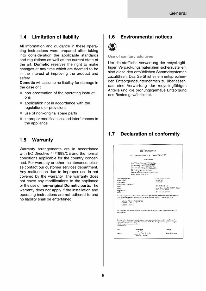
1.7 Declaration of conformity

6
2.0 Safety instructions
Safety instructions
The toilet must be installed by trained staffonly.
The toilet must be in principle installed so that
it is accessible for maintenance work, can be
easily installed and dismantled and removed
from the vehicle without great effort.
2.2 Installation notes
Installation and connection of the sanitationsystem must comply with the latest technicalregulations, as follows:
� The electrical installation must comply with national and local regulations..
� European standards EN 1645-1, EN 1646-1,EN 1648-1 ,
EN 1648-2
2.3 Standards and regulations
CAUTION!
This toilet is designed for installation in recrea-
tion vehicles such as caravans or motorhomes.
2.1 Intended use

7
Description of model
3.0 Description of model
3.1 Model identification
1 = Removable cover and seat2 = Toilet bowl3 = Emptying blade for the toilet bowl4 = Console for water tank5 = Level indicator / control panel (flush)6 = Tankklappe / Einfüllstutzen Frischwasser7 = Service door
1 = Model number2 = Product number3 = Serial number
The identification label contains all important
details. You can read off from this the model
identification, the product number and the
serial number. You will find the identification
label within the cassette housing after remo-
ving the cassette.
3.2 Toilet identification label
2
4
3
1
3.3 Explanation of components
Fig. 2
8 = Cassette tank (capacity 19 l)9 = Pour out spout10 = Vent button for emptying
Fig. 3
5
8
3
10
9
6
7
Fig. 1
1 2 3
CT 3 x x x (S)(W)(LP)
Cassette Toilet
Model range
S = free-standing without flush water tank,withconsole
W = free-standing with integrated flush water tank
LP = Low Profile, low con-sole
Example :

8
Installing the toilet
4.0 Installing the toilet
4.2 Create wall aperture
4.1 Installing the service door
The description for the installation of the servicedoor can be found in the document supplied(Dometic Seitz SK 5) (optional/depending onmodel).
4.3 Installing the toilet
Install the toilet according to the description ofthe respective model. Allow sufficient space soas not to limit the operation of the emptyingvalve.
Install the toilet against an upright wall only.
When installing the toilet in a wet room, werecommend connecting the toilet with the sho-wer tub. The toilet pedestal is fitted with a pro-jecting flange in order to cover the top rim of theshower tub.
All components of the system must be instal-led in frost-protected areas. In minus tempe-ratures there is a risk of damage due to frost.
Fig. 5
CAUTION!
Apply an aperture for the cassette in the wallwith the dimensions ymin =12.5 mm and ymax = 28mm; w = 310 mm and h = 360 mm. The x valueresults from the toilet installation. Observe theposition of the service door.
Fig. 4

9
Installing the toilet
4.3.1.1 Fitting the CT 3xxx toilet
The free-standing CT 3xxx model has no inte-grated water tank. Install this model so that thewall behind it can absorb the control panel ofthe toilet, the electric connections and the watertank, if applicable. It is ideal to set a box in frontof the room wall, as illustrated in Fig. 6. Installthe control and operator panel in immediateproximity to the toilet (see Section 4.3.1.2).
Note that the cassette projects 120 mm (a) outof the cassette housing (Fig. 7). The pedestalheight (b) ranges from 50 to 110 mm, dependingon the model.
4.3.1 Installing the CT 3xxx toilet
Fig.6
Fig. 7
a
b
Once the toilet is installed in the desired posi-tion, bolt down the floor plate with the fourscrews (enclosed) (Fig. 8).
Then attach the toilet housing (with no morethan 7 screws) to the wall (Fig. 9).
Fig. 9
Fig. 8
Fig. 10
Screws d = 4.2 mm
38 /- 0.5 mm
4.5
mm
10
Installing the toilet
Fig. 11
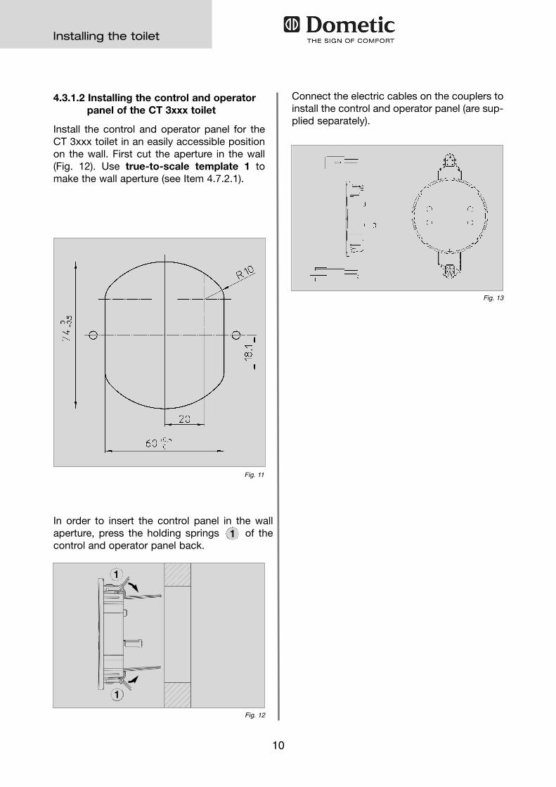
4.3.1.2 Installing the control and operator panel of the CT 3xxx toilet
Install the control and operator panel for theCT 3xxx toilet in an easily accessible positionon the wall. First cut the aperture in the wall(Fig. 12). Use true-to-scale template 1 tomake the wall aperture (see Item 4.7.2.1).
Connect the electric cables on the couplers toinstall the control and operator panel (are sup-plied separately).
In order to insert the control panel in the wallaperture, press the holding springs of thecontrol and operator panel back.
Fig. 12
Fig. 13
1
1
1

11
Installing the toilet
4.3.2.1 Fitting the wall holder
Fit the wall holder (Fig. 16) in the designatedposition (see table, Fig 18).
Fig. 16
Fig. 18
a
b
The CTW 3xxx model has an integrated watertank, while the CTS 3xxx model does not.
The control and operator panel is integrated inthe housing with these models.
Both models can be installed directly againstthe room wall (see Fig. below). To fit the toiletand the console, a previously installed wall hol-der is used (see Section 4.3.2.1).
4.3.2 Installing the CTS 3xxx, CTW 3xxxand CTLP 3xxx toilets
Fig. 14
Fig. 15
Fitting height of the wall holder:
Model a b
CTS / CTW 3000 90 mm 651.5 mm
Fig. 17
12
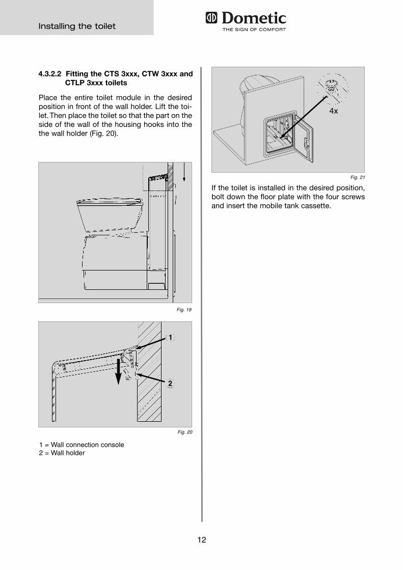
Place the entire toilet module in the desired
position in front of the wall holder. Lift the toi-
let. Then place the toilet so that the part on the
side of the wall of the housing hooks into the
the wall holder (Fig. 20).
4.3.2.2 Fitting the CTS 3xxx, CTW 3xxx and CTLP 3xxx toilets
Fig. 19
1 = Wall connection console2 = Wall holder
If the toilet is installed in the desired position,bolt down the floor plate with the four screwsand insert the mobile tank cassette.
Fig. 21
Installing the toilet
4x
Fig. 20
1
2

13
4.4.2 Water connection for the CTS 3xxx, CTW 3xxx, CTLP 3xxx models
The water supply is connected in the same
way as with the CT 3xxx model via a module
(Fig. 22). The water connection module is
already installed in the console. The CTW 3xxx
model with the integrated water tank already
contains the electric water pump and the filling
nozzles for external fresh water supply.
4.4 Water connectionThe water supply is connected via a module
(Fig. 10) where the water feed hose is atta-
ched. The fresh water tank is linked at con-
nection "1". The toilet flush is provided via
connection "2". Install the water connection
module on the vehicle's wall in an accessible
position (Fig. 23). Wall holder "3" serves to
absorb a module and an optional water tank.
Fit all hose connections with ring clamps and
then check leak tightness.
Always install the water connection module
above the toilet's highest water level (h = min.50 mm).
If the water connection module is installedbelow the water level, there is a risk of foulwater flowing back into the tank.
CAUTION!
4.4.1 Connecting the water supply for the CT 3xxx toilet
Installing the toilet
Fig. 22
21
3
Fig. 23
h

14
Installing the toilet
4.5 Ventilation
Place the ventilation hose on the integratedventilation aperture of the service door as illu-strated.
Open the duct (a) for the ventilation hose in thetop area of the door frame (press out sprayingvarnish on the outside, drill through on theinside).
Fig. 25
Fig. 24
Außenseite Innenseite
aa

15
Installing the toilet
Fig. 26
4.6 Electric connection
Electric connection must be carried out by
trained staff.
4.6.1 System diagrams
CAUTION!
4.6.1.1 System diagram (CTW 3xxx model with integrated water pump)
12V DC
Supply voltage: : 12 V DC
12V connection cable profile : min. 0.75 mm²
Toilet control fuse : 7.5 A (integrated automobile fuse)
Current consumption of the pump : max. 2 A
Control and operator panel

16
Installing the toilet
Fig. 27
4.6.1.2 System diagrams (CT/CTS/CTLP 3xxx models with external water pump)
Supply voltage: : 12 V DC
12V connection cable profile : min. 1.5 mm²
Toilet control fuse : 7.5 A (integrated automobile fuse)
Current consumption of the pump : max. 5 A
12V DC
Control and operator panel
pump
The external water pump must not exceed anominal power of 60 W (12V/5A).
The external water pump is not included in thescope of delivery.
CAUTION!

17
Installing the toilet
Fig. 28
4.6.2.1 Circuit diagram (models with internal water tank, model CTW 3xxx)
4.6.2 Circuit diagrams

18
Installing the toilet
Fig. 29
4.6.2.2 Circuit diagram (models with external water tank

19
Installing the toilet

20
Installing the toilet
4.7 Annex4.7.1 Dimensioned sketches
4.7.1.1 CT 3xxx

21
Installing the toilet
4.7.1.2 CTLP 3xxx

22
Installing the toilet
4.7.1.3 CTS / CTW 3xxx

23
Installing the toilet
4.7.2.1 Template 1 for control and operator panel installation
4.7.2 Templates