wyman gordon rochester institute of technology multi-disciplinary senior design team 12556 kevin...
TRANSCRIPT

WYMANGORDON
ROCHESTER INSTITUTE OF TECHNOLOGY
Multi-Disciplinary Senior Design Team 12556
KEVIN CONWAY (ME, Lead Engineer)
MARK GONZALEZ (ME)
ROBERT HAGEN (EE)
JOE MAJKOWSKI (EE)
JORGE VIANA (ISE, Project Manager)
FORGING LOCATOR
DETAILED DESIGN REVIEW

OUTLINEI. Introduction of Wyman-Gordon
i. Forging Process
ii. Manufacturing Environment
iii. Customer Necessity & Requirements
II. Detailed Design – Electrical Feasibilityi. Sensors and System Orientation
ii. Processing System Design
iii. Data Logging System Design
iv. Electrical Display Design
III. Detailed Design – Mechanical Feasibilityi. Sensor System Bracket Design
ii. Sensor Enclosure Design
iii. Display Design

OUTLINE (continued)IV. Bill of Materials
i. Mechanical Sub-Systemsa. Sensor System Bracket
b. Sensor Enclosure
c. Display Enclosure
ii. Electrical Sub-Systemsa. Sensors
b. Processing System
c. Data Logging System
d. Electrical Display
V. Risk Assessment
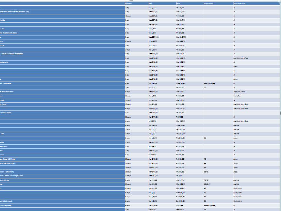
VI. Schedule

WYMAN-GORDON•Global leader in manufacturing of titanium, steel and nickel–based forgings.
• 50,000 ton press National Historic Mechanical Landmark
• 3 Primary Markets Aerospace ( Landing Gear/ Airframe structures) Energy (Various Turbine Engines and components) Military (Airframe structures / Vehicle Armor)

1. Billets are heated to 1700 F-2100 F⁰ ⁰ .
2. Dyes are lubricated with graphite based lubricant (sometimes a non-stick paper).
3. Forklifts transfer the hot billets from the oven to the dye.
4. Workers with crowbars have roughly 60 seconds to position the hot forging within the dye.
5. The operator gets the go-ahead from the workers, the press closes and the billet is forged.
6. The press opens, workers blast the dye with compressed air clearing the debris into the exhaust fans.
7. The forged billet is removed and the process starts all over again.
FORGING PROCESS

Hot
• Dyes < 900oF
• Billets < 2100oF Flames and Smoke
• Graphite based lubricant ignites Flying Debris
• Debris is blown out of the dye using compressed air
• Debris is sucked into the exhaust fans Dirty and Dusty
• Dust had encapsulated the entire forging building due to the grinders
High impact
• Large forklifts
• Worker with crowbars
ENVIRONMENT

• Problem:
• Current Billet Positioning Technique:• Visual Judgment = Art Form
• Majority of the workforce is getting ready to retire.• Lack of a medium for knowledge transfer• Process is currently less systematic
• Leads to $1M in scrap and rework
• Solution:
• Sensor Positioning System
CUSTOMER NECESSITY

Position the billet within + 0.25” of a predetermined position within the dye.
Communicate: Position relative to the ideal position Necessary corrections
Catalog position electronically in reference to the part and job number.
Withstand the harsh environment. Minimal physical and visual interference with
operators and forklift drivers Dynamic/real time feedback throughout process
CUSTOMER REQUIREMENTS

SYSTEM LAYOUT
•3 Major Components Computer Lasers Display
•Computer will be used for data storage and laser interface
•Laser will be used in order to interface with display

Time of flight sensor
Data acquisition and interface software available
RS232 or RS422 serial interfaces
Has been utilized on measuring red hot materials.
Class 2 laser (No eye protection) Red 650 nm
output
Alarm function to supply up to half an amp
Can reference measurement from any point
Measuring Range Black Material .4m - 17m
Resolution .1mm
Repeatability less than .5 mm
Linearity ±2mm (+15°C … +30°C), ±5mm (+30°C
… +50°C)
OPTONCDT ILR1181 LASER DISTANCE SENSOR

Sends out a laser pulse and measures time to receive the beam back.
Theoretically the infrared pulse will have more power than the noise floor making it visible to the sensor.
Word of mouth that this has worked on materials emitting infrared noise
Test plan has been produced to confirm accuracy of laser on heated pieces of material.
TIME OF FLIGHT SENSOR
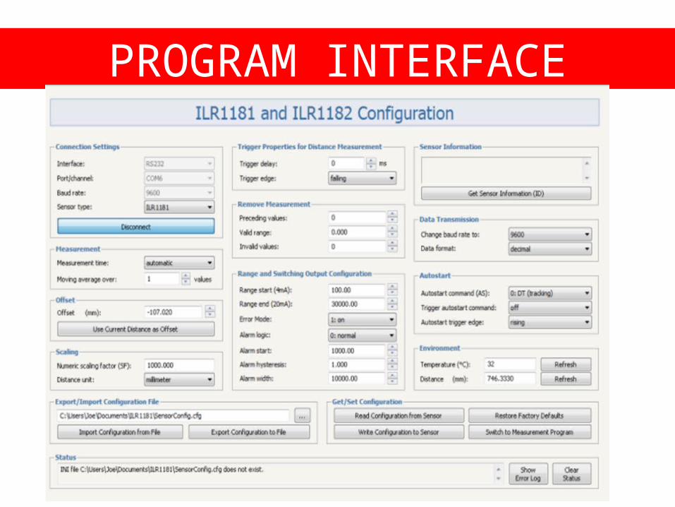
PROGRAM INTERFACE

PROGRAM INTERFACE(CONTINUED)

DATA ACQUISITION
• Data exported into column format in excel.
• File name/path specified in program
• 3 values exported Time Distance Error
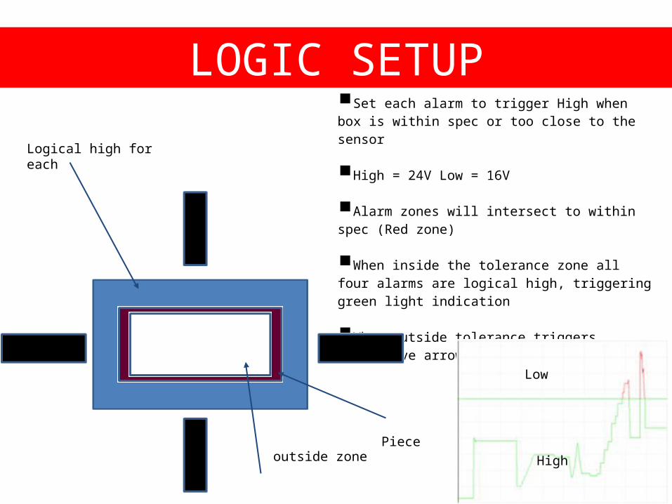
Set each alarm to trigger High when box is within spec or too close to the sensor
High = 24V Low = 16V
Alarm zones will intersect to within spec (Red zone)
When inside the tolerance zone all four alarms are logical high, triggering green light indication
When outside tolerance triggers respective arrow circuit with low signal
LOGIC SETUP
outside zonePiece
Logical high for each
High
Low

When an alarm line is low, circuitry in respective arrow is triggered turning on red LEDs (indicating direction needed to move)
All alarms lines being high, triggers green LED circuitry to turn on center circle giving the go ahead to operators
2 different types of circuit boards needed
DISPLAY

ARROW CIRCUIT SIMULATION Ground is the signal line
When high circuit essential an open(no current flow)
When low, voltage differential of 8V creates current flow of 8.546mA
LEDs have maximum rating of 10mA
LEDs will not be supplied to much current and will turn on

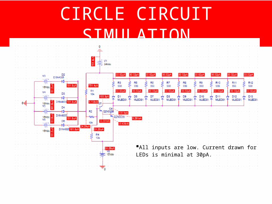
CIRCLE CIRCUIT SIMULATION
All inputs high, no current to diodes, Power BJT is on which allows current to flow through the BJT and the LED's to draw power
9 Green Diodes, max rating of 20 mA
Resistors set to 330 ohms to limit current.
CIRCLE CIRCUIT SIMULATION
All inputs are low. Current drawn for LEDs is minimal at 30pA.

CIRCLE CIRCUIT SIMULATION
Worst case only one input is low.
Circuit still draws small current of 56.6pA
LEDs should not glow with this current.

DISPLAY CIRCUIT PCB
Bottom TopSilk Screen

WIRING HARNESS
RS-422 uses 24/4 shielded wireOther connections 244AWG

MECHANICAL DESIGN

• Protective housing for Sigma-Epsilon Sensors
• Thermal insulation is primary function• Die Temp 700-900 °F• High temperature insulation for use in fire
protection
• Aluminum Housing• 1/8” thick sheet top• ¼” Al Block bottom support• Weight: 9.5 lbs.
• External Port for Sensor Harness
• View hole for Sensor Optics
• Air Purge System• Increase visibility of line-of-sight to
environment• Additional cooling of sensor (secondary
function)
ENCLOSURE

• Determine the necessary thermal conductivity (k-factor) of the insulation (0.875” thk) to provide acceptable operating temperatures for the sensor (50°C)
• Radiation dominated heat transfer problem• Assumptions:
• qrad = qconv
• The bulk temperature for convection was 900 °F (773 K)
• h = 15 W/m2*K (free convection of air)
• Excluded Forced convection within box
• Aluminum outer case • 0.125” thick (0.00317 m)
• ɛ = 0.18 , k = 218 W/m*K
• Area = 29.44 in2 (0.0189 m2)
• Results• @ 0.875” thk, k = 0.116 W/m*K (0.067 Btu/h-ft-F )
• Chosen Material: k @ 427 °C (900 °F) : 0.115 W/m*K
ENCLOSURE


• Provides Horizontal and Vertical Motion• Allows sensors to view distinct billet
geometries
• Aluminum/Steel Build• Al blocks, Al Square Tubing, Steel Blocks
• Weight: 24 lbs.
• Horizontal Travel• Steel Rail Guide (double track T-slot)
• Supports Enclosure & Vertical Adjustment
• Fixed w/ Set screw to Rail.
• Vertical Adjustment (Telescoping Bars)• 5” Adjustable Height
• Height Maintained w/ Set screw (0.375”)
• Die Measuring Configuration• Sensor w/o Telescoping feature
• Located lower (rests on Steel Rail Guide)
ENCLOSURE SUPPORT

Exploded View Die Measuring Configuration
ENCLOSURE SUPPORT (CONTINUED)

• Find necessary pressure applied from set screw to hold sensor up
• Basic Static Problem w/ friction
• Parameters • Weight: 14.24 lbs.
• Friction coefficient (Al –Al dry): 1.05
• Area of contact( minimal): 2.625 in2
• Results• The Set-screws require a maximum of
5.2 psi of pressure to maintain static equilibrium
SET SCREW ANALYSIS

• Rests on Shoe of Die Press
• Provides horizontal motion to all sensors• Length: 4 ft.
• Aluminum/Steel Build• Al Sheet, Al Square Tubing, Steel Block
• Weight w/o sensors: 43lbs. ( 88 lbs. in configure shown)
• Magnetic Feet Attachment (not shown)• Prevents movement before/during/after press
processing
• Maintains location for accurate readings
RAIL SUPPORT SYSTEM

MAGNET HOLD DOWN SUPPORT
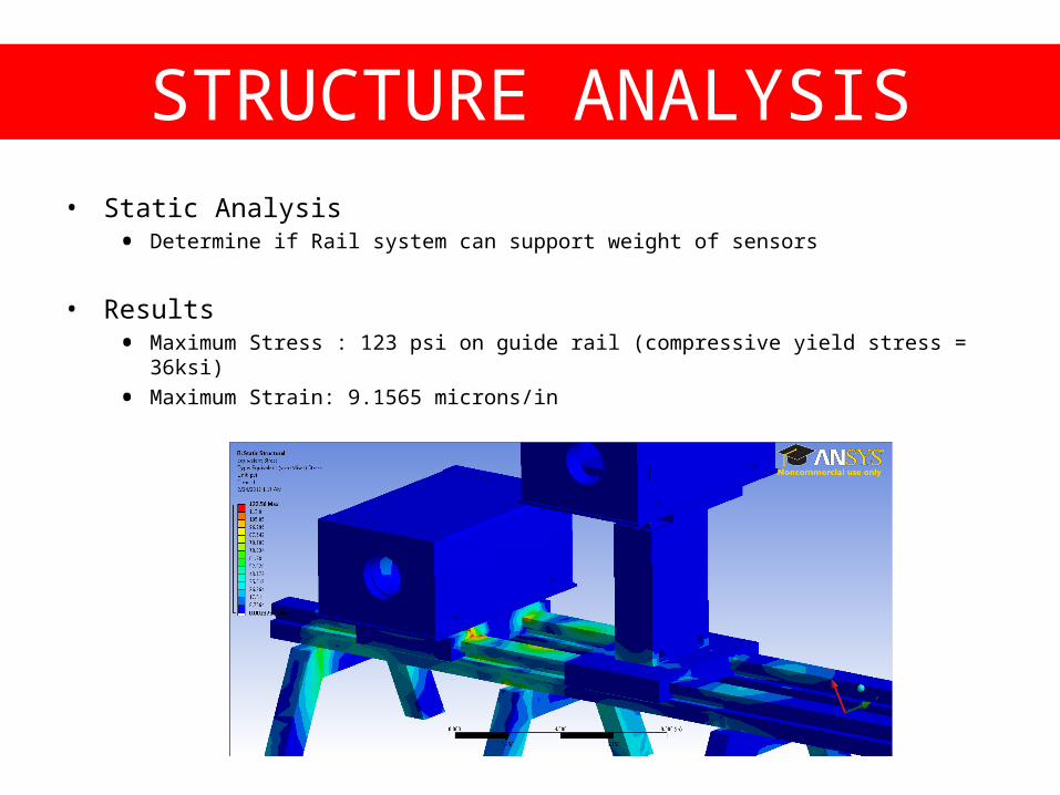
• Static Analysis• Determine if Rail system can support weight of sensors
• Results• Maximum Stress : 123 psi on guide rail (compressive yield stress = 36ksi)
• Maximum Strain: 9.1565 microns/in
STRUCTURE ANALYSIS

DISPLAY ENCLOSURE

DISPLAY ENCLOSURE

AIR PURGE SYSTEM

AIR PURGE SYSTEM

AIR PURGE SYSTEM

TEST AND ASSEMBLY PLANS
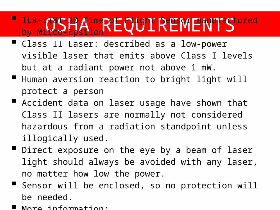
OSHA REQUIREMENTS ILR-1181-30 Time of Flight Sensor manufactured by Mirco-
Epsilon Class II Laser: described as a low-power visible laser that emits
above Class I levels but at a radiant power not above 1 mW. Human aversion reaction to bright light will protect a person Accident data on laser usage have shown that Class II lasers
are normally not considered hazardous from a radiation standpoint unless illogically used.
Direct exposure on the eye by a beam of laser light should always be avoided with any laser, no matter how low the power.
Sensor will be enclosed, so no protection will be needed. More information:
http://www.osha.gov/dts/osta/otm/otm_iii/otm_iii_6.html

SUMMARY OF HAZARDS
UV and Near-Infrared (NIR) wavelength ranges do not apply to Class II Lasers.
VIS (Visible) wavelength ranges do apply to Class II Lasers.
NO fire or diffuse ocular hazards. Direct ocular hazards will occur only after
0.25 seconds of being exposed.

BILL OF MATERIAL (BOM) Divided in 3 sections: Electrical, Mechanical and
Supplementary Parts. Consists of Part Description, Part Number,
Manufacturer, Vendor, Unit Price, Quantity, Price, Lead Time, and Link.
Most vendors authorized by RIT. Biggest Expense: TOF Sensor by Micro-Epsilon at
$1,840 each ($11,040 total). Initial Budget of $15,000, flexible according to needs. Total expenses with a 5% Contingency on the Total
Price: $19,300


RISK ASSESSMENT

MAJOR RISKS Lead Times Sensors not being adequate for
customer needs. Components not interfacing. Miscommunication with customer. Failures due to temperature or interference. Exposure to Water. Tolerances are not met. The equipment is not deployable at location.
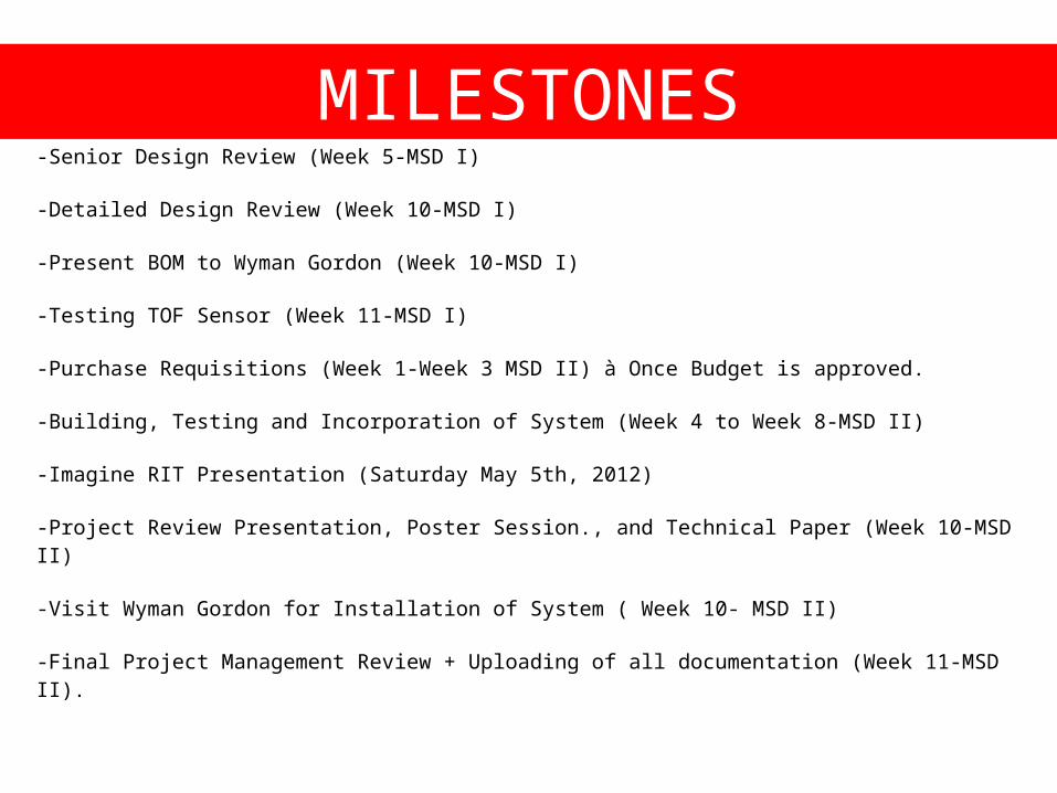
MILESTONES-Senior Design Review (Week 5-MSD I)
-Detailed Design Review (Week 10-MSD I)
-Present BOM to Wyman Gordon (Week 10-MSD I)
-Testing TOF Sensor (Week 11-MSD I)
-Purchase Requisitions (Week 1-Week 3 MSD II) à Once Budget is approved.
-Building, Testing and Incorporation of System (Week 4 to Week 8-MSD II)
-Imagine RIT Presentation (Saturday May 5th, 2012)
-Project Review Presentation, Poster Session., and Technical Paper (Week 10-MSD II)
-Visit Wyman Gordon for Installation of System ( Week 10- MSD II)
-Final Project Management Review + Uploading of all documentation (Week 11-MSD II).