wx10000.1 technical paper - kicker...control (crossovers, subsonic fi lter, bass boost, limiter,...
TRANSCRIPT

WX10000.1Technical Paper
SignalModulatedMonoChannelSubwooferAmplifi er

WX10000.1TechnicalManual
Warhorse: Defi ned as “Horses specially trained for use in battle or individual combat”.
As early as the 19th Century BC the Warhorse was used in chariot warfare. By the fi rst century BC the Warhorse carried Parthian archers into battle. By the Middle Ages the Warhorse had developed into a large horse with the strength and stamina to carry a Knight and his heavy armor into battle. The Warhorse of this era wore its own armor and was a magnifi cent beast. The best were selected for speed and trainability. It was an expensive feat to train and outfi t these tools of war. It took a lot of time to overcome the natural aversion to the smell of blood and its natural disinclination to trample people. They were even trained to kick, strike and bite on command.
In light of all this, Kicker’s newest and largest amplifi er is named Warhorse. Born to do battle and trained to excel, the Warhorse is like nothing available in the car audio arena. Conventional wisdom and technology weren’t good enough for Kicker when we designed this 10,000 watt beast. Traditional Class A/B design was entirely too ineffi cient and even more advanced Class D architecture wasted too much battery power.
Effi ciency is the “Holy Grail” of car stereo amplifi cation, especially in SPL competition lanes. Warhorse’s ultra-high effi ciency allows competitors (as well as power hungry consumers) to create the huge amounts of power they demand without relying on huge banks of amplifi ers and the correspondingly huge charging systems required with conventional amplifi ers. By approaching the challenge of delivering massive power from a new direction, Kicker engineers have created a system that lets users concentrate their investments where they count – in actual sound reproduction equipment, instead of batteries, alternators, or other charging system components. Signal quality is also critical to the demanding high-end user, so in addition to the amplifi er’s prodigious output capability, a full complement of built-in control (crossovers, subsonic fi lter, bass boost, limiter, and more) allow precise tuning of your bass. A broad assortment of protection and diagnostic circuits are also provided, allowing further performance optimization.
KICKER’S signal-modulated power supply technology represents the fi rst signifi cant advance in amplifi er effi ciency since Class D designs overtook Class A/B. Even though Class D was a great improvement over A/B, Around 30% of available power was still wasted. While earlier technologies use power supplies combined with gain circuits to amplify the audio signal, the Warhorse amplifi es the audio signal directly
1

WX10000.1TechnicalManual
from its signal-modulated power supply, eliminating many power-wasting components common to conventional designs. The signal-modulated power supply amplifi es each polarity of the audio signal separately through two voice coil outputs, each driving one coil of a dual-voice coil subwoofer or DVC subwoofer array. This fresh approach… essentially a power supply with gain… results in effi ciencies greater than 90%! SPL competitors will fi nd this very attractive and advantageous as they seek to wring those elusive last few decibels from their vehicle. Consumers anxious to experience cutting edge technology will appreciate the amplifi er’s ability to interface with a broad range of components and vehicles.
The idea of a signal modulated power supply directly driving the subwoofers is an idea that we have thought about for a few decades. Combining the conventional power supply with the amplifi er section results in higher effi ciency than is possible with established designs. When building an amplifi er this powerful, effi cient conversion of battery power to audio power is critical.
The basis for the Warhorse is anchored in conventional designs. There are two large DC-to-DC pulse width modulated converters with ratios of 1:19. One converter is a positive power supply and the other is a negative supply. Combined they are capable of 400V of peak to peak output. These power supplies are designed to have no output until they are told to by the audio signal. Without a signal the converters are running with the minimum pulse width.
These large converters have to be bulletproof. The MOSFETs used to do the switching are rated at 75 Volts and 170 Amps. Since there are 32 of these MOSFETs on each side of the power supply the combined current capability is 10,880 Amps! With the output short-circuit protected at 90 Amps, the maximum capability of the Warhorse is 12,690 Watts. That should qualify as overbuilt. The MOSFETs chosen are the best devices to get the job done. Their typical 3.6 mili-ohms of “on” resistance is the best available for this application, resulting in best-case effi ciency.
The small-signal processing is done in the digital domain using a modern Texas Instruments 150 M Hz CMOS 32 bit CPU. This processor has a 12 bit ADC and 16 channels.
The Warhorse has multiple “housekeeping” power supplies to operate the processors, LEDs, protection circuits and preamp parts. They include a + 12 Volt, +/- 5 Volt and a +3.3 Volt supply.
Transformers are among the most important parts in a high-powered mobile amplifi er. KICKER engineers were tasked with building a no-compromise amplifi er, so no-compromise transformers were paramount. Back in the 80’s our military began using Planar transformer design for their desirable properties. We use very special proprietary Planar transformers designed and prototyped in the Kicker R&D department. Production of the transformers in quantity has been sourced from Tunisia. There is only one source for transformer cores this large. The cores are rated at 5,000 watts each and four are in each Warhorse amplifi er.
2
WX10000.1TechnicalManual
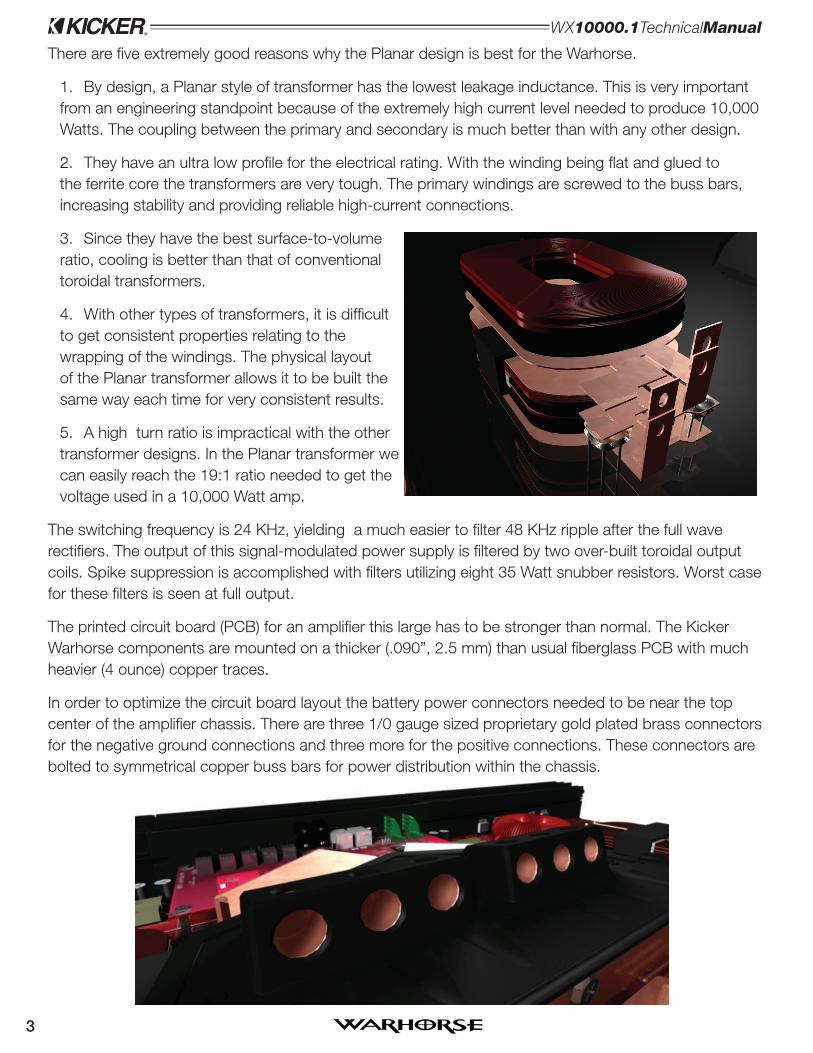
There are fi ve extremely good reasons why the Planar design is best for the Warhorse.
By design, a Planar style of transformer has the lowest leakage inductance. This is very important 1. from an engineering standpoint because of the extremely high current level needed to produce 10,000 Watts. The coupling between the primary and secondary is much better than with any other design.
They have an ultra low profi le for the electrical rating. With the winding being fl at and glued to 2. the ferrite core the transformers are very tough. The primary windings are screwed to the buss bars, increasing stability and providing reliable high-current connections.
Since they have the best surface-to-volume 3. ratio, cooling is better than that of conventional toroidal transformers.
With other types of transformers, it is diffi cult 4. to get consistent properties relating to the wrapping of the windings. The physical layout of the Planar transformer allows it to be built the same way each time for very consistent results.
A high turn ratio is impractical with the other 5. transformer designs. In the Planar transformer we can easily reach the 19:1 ratio needed to get the voltage used in a 10,000 Watt amp.
The switching frequency is 24 KHz, yielding a much easier to fi lter 48 KHz ripple after the full wave rectifi ers. The output of this signal-modulated power supply is fi ltered by two over-built toroidal output coils. Spike suppression is accomplished with fi lters utilizing eight 35 Watt snubber resistors. Worst case for these fi lters is seen at full output.
The printed circuit board (PCB) for an amplifi er this large has to be stronger than normal. The Kicker Warhorse components are mounted on a thicker (.090”, 2.5 mm) than usual fi berglass PCB with much heavier (4 ounce) copper traces.
In order to optimize the circuit board layout the battery power connectors needed to be near the top center of the amplifi er chassis. There are three 1/0 gauge sized proprietary gold plated brass connectors for the negative ground connections and three more for the positive connections. These connectors are bolted to symmetrical copper buss bars for power distribution within the chassis.
3

WX10000.1TechnicalManual
Since the output current to the subwoofers can reach 90 amperes, the connectors must be extremely rugged. We chose AndersonTM connectors because they have been proven to hold up under demanding high current applications (such as industrial fork lifts). They are also ideal due to the fully enclosed design which helps eliminate the chance for electrocution. The output current is monitored by surface mount resistors that are referenced to ground and calibrated for 90 amps RMS. When that level is reached the DSP controller shuts the amplifi er down in microseconds to prevent damage to any components.
The switching MOSFETs need to be bulletproof, so they utilize thermally conductive interface material. This insulated metal substrate minimizes the thermal impedance and conducts heat away from the MOSFETs more effi ciently than conventional mounting methods.
In conclusion, the Kicker Warhorse WX10000.1 has the highest power output available in a single channel mobile amplifi er, the best conversion effi ciency from battery power to audio power, the lowest idle current and the best power to size/weight ratio.
0
20
40
60
80
100
%E
FF
ICIE
NC
Y
KICKER PATENT PENDING SIGNAL-MODULATED DESIGN
HIGH QUALITY CLASS D DESIGN
POWER OUTPUT (KW)
0.1 0.2 0.5 1.0 2.0 4.0 8.0 10
90%
75%
401302008-b+WX10000

WX10000.1AMPLIFIER
Authorized Kicker Dealer:
Purchase Date:
Amplifier Model Number:
Amplifier Serial Number:
__________________________
__________________________
__________________________
__________________________
WX10000.1Signal-ModulatedMonoChannel
WX.1SeriesAmplifierOwner’sManual
Congratulations on yourKICKER purchase!
Please record your purchaseinformation and keep your salesreceipt for validation of warranty.
INS
TALL
AT
ION
0
20
40
60
80
100
%E
FF
ICIE
NC
Y
KICKER PATENT PENDING SIGNAL-MODULATED DESIGN
HIGH QUALITY CLASS D DESIGN
POWER OUTPUT (KW)
0.1 0.2 0.5 1.0 2.0 4.0 8.0 10
90%
75%
The Kicker Warhorse amplifier was specifically designed for competition car audio. Sporting 10,000RMS watts of pure Kicker power, the ultra-high-efficiency design of the WX amplifier revolutionizestraditional methods of amplification. While most amplifiers use a power supply combined with anamplification circuit to amplify the audio signal, the Warhorse skips a step by amplifying the audiosignal directly from its patent pending signal-modulated power supply. The signal-modulated powersupply amplifies each polarity of the audio signal separately through its two voice coil outputs tooptimally drive dual-voice coil subwoofers and provide a competitive edge in SPL contests. From goldplated power connectors and low profile planar transformers to the latest Texas Instruments DSPtechnology, no expense was spared to make the Warhorse the most powerful and efficient monoamplifier in mobile audio.
Installation . . . as easy as 1, 2, 3
1. Mounting Choose a structurally sound location to mount your Kicker amplifier. The amplifier shouldbe mounted as close as possible to the battery network and be electrically isolated from the vehicleground. The distance from the battery network to the amplifier should not exceed 48” (122cm). It isimportant to mount the amplifier before running any wires or supplying power to the amplifier. Theamplifier secures to the vehicle with an insertable mounting bracket used in combination with twomounting holes located on the bottom plate of the control panel. You are solely responsible for securelyfastening the WX amplifier in your vehicle.
Before mounting the amplifier, the control panel shield must be removed. The control panel shouldremain accessible for adjustment, leaving enough room to access the mounting holes and remove orattach the control panel shield. Make sure there are no items behind the area where the screws will bedriven. Choose a location that allows at least 4” (10cm) of open ventilation for the amplifier. Afterchoosing the best location, secure the mounting bracket to the vehicle. Use the bracket as a templateto drill nine (9) holes with a 3/16” (4.8mm) bit into the appropriate locations. Attach the bracket to themounting location with the nine (9) supplied #10 (5mm) screws inserted through the nine (9) includedscrew insulators.
Next, slide the amplifier over the mounting bracket and into the mounting slot. Make sure the mountingbracket is properly inserted into the mounting slot and locate the two mounting holes on the bottomplate of the control panel. Use the mounting holes as a template and drill two (2) holes using a 3/16”(4.8mm) bit into the appropriate locations. Secure the bottom plate of the control panel with the two (2)#10 (5mm) screws.
Caution The Kicker WX amplifier outputs extremely high voltage signalsfrom the voice coil (speaker) outputs and can cause serious injury or deathfrom electrocution. It is imperative to read the manual carefully and follow allof the recommended safety precautions before installing the WX amplifier.
The patent pending signal-modulateddesign of the Warhorse amplifier is themost powerful and efficient designavailable in mobile audio, rated at 90%efficiency at full power with a 2 ohm load.The graph compares the Warhorseamplifier’s efficiency ratings to those ofindustry standard Class D amplifiers.
Figure 1
Model:SubwooferAmplifier
WX10000.1
5

6
Figure 2
Control Panel Shield
Mounting Bracket
Nine (9) SuppliedScrew Insulators
Nine (9) Supplied#10 (5mm) screws
Mounting Bracket
Warhorse Amplifier
Mounting Holes
Control Panel(Top View)
Remove the two (2) screwssecuring the control panelshield to the amplifier chassis.
Remove the control panel shield from theamplifier so the mounting holes on the bottomplate of the control panel will be accessible.
Before mounting the amplifier, be sure there is adequate space in the mounting positionto take the control panel shield on or off and to easily access the amplifier’s controls.
After determining the best mounting position for the amplifier, use the mounting bracket as a template to drillnine (9) holes with a 3/16” (4.8mm) bit into the appropriate locations. Attach the bracket to the mountinglocation with the nine (9) supplied #10 (5mm) screws inserted through the nine (9) included screw insulators.
Slide the Warhorse over the mounting bracket and insert the mountingbracket into the mounting slot on the bottom of the amplifier.
Locate the additional mounting holes on the bottom plate of the control panel. Use the mounting holes as a templateto drill two holes using a 3/16” (4.8mm) bit into the appropriate locations. Secure the bottom plate of the control panelwith the two (2) #10 (5mm) screws. You are solely responsible for securely fastening the amplifier in your vehicle.
INS
TALLA
TIO
N
1.
2.
3.
4.
5.
The amplifier is very heavy.Assistance may be necessaryto lift and position the amplifier.

7
2. Wiring Before wiring the Warhorse amplifier, disconnect the vehicle’s batteries to avoid an electricalshort. Eight (8) identical, high-quality, 800-cold-cranking-ampere (cca), 12-volt batteries arerecommended to power the WX amplifier. All power and ground wires should be as short as possibleand utilize 1/0 gauge wire. Remove the wire guide and power hood from the amplifier as shown inFigure 3. Connect three (3) ground wires from the amplifier’s negative power connector to the negativeterminals of three (3) batteries in the battery network.
From two (2) of the batteries in the battery network, connect 1/0 gauge ground wire from the negativeterminals of the batteries to a paint-free and corrosion-free solid-metal area of the vehicle's chassis.Make the ground wires short, 18” (45cm) or less. To reduce noise, make sure the ground wires connectto the same piece of metal and are within 18” (45cm) of each other.
With the control panel shield removed, connect a twisted pair of RCA (low-level) interconnect cable,carrying the incoming audio signal, to the RCA inputs on the amplifier. Connect the speaker wires to thesupplied AndersonTM connectors. Use 8 gauge wire and strip 9/16” (14mm) from the end beinginserted into the metal contacts. See Figure 5. The wire should be secured by placing the metal contactinto a vise and melting solder inside the metal contact. Then, insert the stripped wire into the moltensolder within the contact. Do not use acid core solder.
The Warhorse amplifier requires at least two (2) 200-ampere-output-capacity alternators. For eachalternator, connect a 250 ampere fuse within 18” (45cm) of each alternator and a second 250 amperefuse within 18” (45cm) of the battery network. Without adequate charging capability, the WX amplifiercan draw enough current to shut down your vehicle’s computer system. This may adversely affect yourability to control your vehicle. See Figure 4.
The three (3) positive 1/0 gauge power wires should be the last wires connected in the installation.Install the supplied Kicker three (3) gang ANL fuse holder within 18” (45cm) of the battery network andin-line with the three (3) power cables connected to the amplifier’s positive power connector. Improperconnections will damage the amplifier and/or cause serious injury or death. If you ever need to removethe amplifier from the vehicle after it has been installed, the ground wires should be the last wiresdisconnected from the amplifier, just the opposite as when you installed it. See Figure 4.
INS
TALL
AT
ION
WX10000.1AMPLIFIER
If you have more questions about the installation or operation of your new KICKER product, see theAuthorized KICKER Dealer where you made your purchase. For more advice on installation, click on theSUPPORT tab on the Kicker homepage, www.kicker.com. Choose the TECHNICAL SUPPORT tab,choose the product or subject you are interested in, and then view the corresponding information. PleaseE-mail [email protected] or call Technical Services (405) 624-8583 for unanswered or specific questions.
Power HoodWire Guide
Note: To get the best performance from your new Kicker Amplifier, we recommend using genuine Kicker Accessories and Wiring.All specifications and performance figures are subject to change. Please visit the www.kicker.com for the most current information.
Figure 3

8
Figure 5Strip Wire
9/16” (14mm) AndersonTM Connector
8 Gauge Speaker Wire
Metal ContactsSecure wire to metalcontacts by soldering.
ModelWX10000.1 Fuse Three (3) x 250 Ampere PowerGroundWire Three (3) x 1/0 Gauge
+12V
+12V
+12V
+12V
+12V
18"
Or
Less
(45c
m)
18"
Or
Less
(45c
m)
18"
Or
Less
(45c
m)
18"
Or
Less
(45c
m)
+12V
+12V
+12V
18"
Or
Less
(45c
m)
At least two (2) 200-ampere alternators arerequired to power the Warhorse amplifier.
Run two (2) ground wires fromseparate negative batteryterminals. Ground wires shouldconnect to vehicle chassiswithin 18” of each other.
Eight (8) identical, high-quality, 800-cca, 12-voltbatteries are recommendedfor optimum performance. 250 ampere
fuse250 ampere
fuse
250 amperefuse
250 amperefuse
ANL fuse holdercontains three (3) 250ampere fuses. The fuseholder should beinstalled within 18” ofbattery network.
Mount Amplifier within 48”(122cm) of Battery Network
-+
Figure 4
3. Configuration The following diagram shows the recommended mono configuration for yourKicker WX amplifier. The WX amplifier can only drive extremely high-power-rated, dual-voice coilspeakers. We recommend using one or more Kicker SoloX Subwoofers. Each voice coil (speaker)output is rated at 2 ohms minimum.
Warning: This amplifier is not like anything youhave ever hooked up before. Pay closeattention to the wiring diagrams in this manual.Improper connections will damage the amplifier.
Negative PowerConnector
Positive PowerConnector
CO
NF
IGU
RA
TIO
NWithout adequatecharging capability, theWX amplifier can drawenough current to shutdown your vehicle’scomputer system. Thismay adversely affectyour ability to controlyour vehicle.
The WX amplifier outputs dangerous voltage levels from the voicecoil (speaker) outputs and can cause serious injury or death fromelectrocution. Never contact the voice coil outputs, connectspeakers, or contact speaker wires while the amplifier is turned on.
Caution The Kicker WX amplifier outputs extremely high voltage signalsfrom the voice coil (speaker) outputs and can cause serious injury or deathfrom electrocution. It is imperative to read the manual carefully and follow allof the recommended safety precautions before installing the WX amplifier.
Improper connections will damage theamplifier and/or cause serious injury ordeath. Be sure that all wiring isconnected to the appropriate polarity.
or
less
or
less
or
less
or
less
or
less

9
The WX amplifier outputs dangerous voltage levelsfrom the voice coil (speaker) outputs and can causeserious injury or death from electrocution. Nevercontact the voice coil outputs, connect speakers, orcontact speaker wires while the amplifier is turned on.
Voice Coil 1 Voice Coil 2
Voice Coil 1 Voice Coil 2
Voice Coil 1 Voice Coil 2
Figure 7
Mount the metal bracket
Back View
Side View 4 ConductorPhone Cable
Slide thehousing untilit snaps into
the metalbracket
Voice Coil 1 Voice Coil 2
Coil 1
Use 8 Gauge Speaker Wire
2 Ohm Dual-Voice Coil Subwoofer
Two (2) 4 ohm Dual-Voice Coil Subwoofers
- +
Coil 2
Figure 6
Minimum2 OhmLoad
Minimum2 OhmLoad
Minimum2 OhmLoad
Minimum2 OhmLoad
- +
- +
Minimum2 OhmLoad
Minimum2 OhmLoad
- +
Coil 1
Coil 2
Coil 1
Coil 2
Coil 1
Coil 2
Coil 1
Coil 2
Four (4) 2 ohm Dual-Voice Coil Subwoofers
WX10000.1AMPLIFIER
- + - +
CO
NF
IGU
RA
TIO
N
-
+
-
+
-
+
-
+
-
+
-
+
-
+
-
+
-
+
-
+
Use 8 Gauge Speaker Wire
Use 8 Gauge Speaker Wire
Coil 1
Coil 2
-
+
-
+
Coil 1
Coil 2
-
+
-
+
Voice Coil 1 +
Voice Coil 1 -
Voice Coil 2 +
Voice Coil 2 -
Series Wire
Wiring Key
Use 8 Gauge Speaker Wire

10
Operation
Within the control panel shield, the Kicker WX amplifier has five (5) rotary controls, input jacks for theRemote Bass level control, and input/output jacks for the optional WX control module. The controlpanel delivers a full range of options for processing the signal that powers your subwoofers. To removethe control panel shield, simply remove the two (2) screws as shown in Figure 5.
1. InputGainControl The input gain control is not a volume control. It matches the output of thesource unit to the input level of the amplifier. Please use hearing protection before performing thefollowing procedure. Disconnect the Remote Bass level control and turn the source unit up to about3/4 volume (if the source unit goes to 30, turn it to 25). Next, slowly turn (clockwise) the gain on theamplifier up until you can hear audible distortion, then turn it down a little.
2. BassBoostControl The bass boost control is designed to give you increased output 0 - 18dB at 40 Hz. The setting for this control is subjective. If you turn it up, you must go back and adjust theinput gain control to avoid clipping the amplifier.
3. HighPassSubsonicCrossover The variable high-pass crossover located on the control panelutilizes a 24dB per octave 20 - 60Hz high-pass crossover. The setting for this control is subjective butshould be adjusted to appropriately accommodate your enclosure in order to prevent damage from highexcursion and increase the power handling of the subwoofer(s).
4. LowPassCrossover The variable low-pass crossover located on the control panel utilizes a 24dB per octave 50 - 200Hz low-pass filter. The setting for this control is subjective; 80 Hz is a goodplace to start.
5. AdjustableLimiterControl The limiter adjusts the maximum RMS output of the Warhorse. If yourvehicle’s charging system is inadequate to provide full power to the WX series amplifier, adjust the limitercontrol clockwise to reduce the amplifier’s power consumption and maintain an operational level that willprotect your subwoofer(s) from damage. If the <VOLT LED is on and the amplifier is frequently shuttingdown due to under voltage, try turning the limiter control up (clockwise) until this is no longer a problem.
6. RemoteBass(Level Control) With the remote bass level control, you have the ability to control thelevel of the subwoofer(s) remotely. To mount the remote bass level control, simply screw the metalbracket to the chosen location. Then slide the housing onto the bracket until it snaps into place. Runthe cable from the controller to the “Remote Bass” jack on the amplifier chassis. See Figure 6.
7. WarhorseControlModule The optional Warhorse control module opens up a wide range ofoperational possibilities within the Warhorse. The control module can simultaneously control up to 16WX amplifiers and puts additional signal processing features in the palm of your hand. These includebandpass crossover with adjustable slopes, limiter adjustment, phase inversion, single-band parametricequalization, voltage range adjustment, battery voltage display, tone generator, and individual amplifiermuting. Contact your Kicker dealer for more information about the Warhorse control module and itsfeatures. It is necessary to purchase the control module to access the full range of possibilities availablefrom your Kicker Warhorse amplifier.
OP
ER
AT
ION
Hz
50
70
95
125
155
185
200
V
5
3.5
1.6
0.8
0.4
0.25
0.17
dB
0
2.5
5.5
9
12.5
15
18
Hz
20
25
30
40
45
55
60
%RMS
100
80
50
30
20
15
10
Figure 9
The corresponding value foreach marker is given for each ofthe Warhorse amplifier’s rotarycontrols to assist in the preciseadjustment of your system.
Figure 8

11
4. >VOLT LED on/off The Over Voltage LED turns on when the voltage supplied to the amplifierexceeds 16 volts and the muted safe mode has been activated. After the voltage supply drops below15.5 volts, the amplifier will automatically turn back on.
5. X-BNDW LED on/off Because of the combined high pass and low pass filters built into therotary control section of the amplifier, it is possible to cause a reduction in output by adjusting thebandwidth too narrow or overlapping the high and low pass crossover frequencies. The X-BNDW LEDturns on if this has occurred and is causing a reduction in output.
6. >TEMP LED on/off If the temperature of the amplifier’s heatsink exceeds 158F (70C), it willactivate the muted safe mode. When the temperature decreases to 149F (65C), the amplifier willautomatically turn back on. If this LED is on, turn the amplifier off and test resistance at the speakerterminals with a digital multimeter (see Figure 6 in this manual for multiple speaker wiring suggestions).Also, check for adequate airflow around the amplifier.
7. Short LED on/off The short LED will light up if the electrical current coming out of the amplifier’svoice coil (speaker) outputs exceeds a peak of 130 ampere. The Warhorse Amplifier tests the outputsevery three (3) seconds to protect the amplifier from electrical shorts and will turn off automatically if anyshort is detected. With the amplifier turned off and speakers disconnected, check for speaker wiresshorted to each other or to the vehicle’s chassis. Check for damaged speaker(s), or speaker(s)operating below the minimum recommended impedance. Because of the dangerous voltage output ofthe amplifier, it is important to turn the amplifier off before attempting to repair any short or problem withthe voice coil output wiring.
8. Service LED on/off If the service LED turns on, the amplifier most likely requires repair. In somecases, the service LED will illuminate if the voice coil (speaker) outputs are not both loaded at the sametime. Turn the amplifier off and check the wiring for abrasions. Make sure that the amplifier is wiredcorrectly to the speakers as indicated in Figure 6. If no problems are found with the speaker wire orconnections and the service LED remains on, contact the Authorized Kicker dealer from whom youpurchased the amplifier.
WX10000.1AMPLIFIER
OP
ER
AT
ION
TroubleShooting
If your amplifier does not appear to be working, check the obvious things first: such as blown fuses,poor or incorrect wiring connections, incorrect setting of crossover switch and gain controls, etc. Thereare eight LEDs on the control panel of your Kicker WX series amplifier. The LED display may helpidentify the problem. The amplifier’s protection circuitry induces a muted safe mode if any excessiveconditions have occurred outside of the amplifier’s normal operational range. These conditions areindicated by the LEDs on the amplifier’s control panel.
1. PWR LED on/off Smart power indicator turnson when the amplifier is on and functioning properly.
2. NET LED on/off Indicates the optional remotecontrol module is connected to the Control ModuleDIN input on the amplifier. See Figure 8.
3. <VOLT LED on/off The Under Voltage LEDturns on when the voltage supplied to the amplifier drops below 9 volts. The amplifier will remain in themuted safe mode until the voltage supply increases to 9.5 volts. If the amplifier goes into mute modeoften, as a result of under voltage, you may need to do one or more of the following: a) turn up thelimiter control on the amplifier’s control panel, b) check the connections, c) replace batteries withidentical units or charge existing batteries, d) add additional identical batteries to the vehicle’s batterynetwork, e) add an additional alternator to your vehicle.
The Warhorse LED arraydisplays the status of theamplifier’s protectivecircuitry and can assist introubleshooting problemsthat may occur while usingthe amplifier. The greenLED’s will turn on or offdepending on theconditions listed in thissection.
Figure 10
Without adequate charging capability, the WX amplifier can drawenough current to shut down your vehicle’s computer system.This may adversely affect your ability to control your vehicle.
The WX amplifier outputs dangerous voltage levels from the voice coil (speaker) outputs.Never contact the voice coil outputs, connect speakers, or speaker wires if the amplifier isturned on. Turning the amplifier on without loading both voice coil outputs or connectingthe speaker(s) will increase the risk of electrical shock and could damage the amplifier.

12
PE
RF
OR
MA
NC
E
Performance
XledoM 10000.1
RMS Power in Watts @14.4V, 2Ω Mono, ≤ 1 x 00001N+DHT %[email protected], 4Ω Mono, ≤ 1 x 0005N+DHT %5.1
)mm888( ”53:htgneL)mm69( ”4/33 :thgieH)mm054( ”4/3 71 :htdiW )gk3.03( bl 8.66:thgieW
zH 002 - zH 02 :Bd 1 - / 0 + ,esnopseR ycneuqerFrewop detar :er ,dethgiew-a ,Bd 59> :oitaR esioN-ot-langiS
,level wol V 5 - Vm 071 :ytivitisneS tupnIevatco rep Bd42 ,zH002 - 05 ,ssaP-woL elbairaV :revossorC ssaP woL
High Pass Sub-Sonic Crossover: Variable High Pass, 20 - 60Hz, 24dB per octave zH 04 @ tsoob Bd 81+ ot 0 elbairaV :tsooB ssaB
WarhorseDesignFeatures
1. Patent Pending Signal-Modulated Power Supply The WX amplifier’s patent pending signalmodulated power supply combined with its custom planar transformers achieves efficiency ratings yetto be matched in mobile audio, operating at 90% efficiency at a 2 ohm load and 93% efficiency at a 4ohm load at full power.
2. Planar Transformer Design The WX amplifier’s four (4) planar transformers are excellent for highpower applications and are custom designed to handle 5,000 watts each, leaving more than enoughpower headroom to operate reliably and consistently at full RMS with 20,000 watts of total capability.
3. Texas Instruments DSP The Warhorse uses the latest Texas Instruments industrial grade DSP tohandle the amplifier’s pulse-width modulation, manage signal processing, and control the amplifier’sprotection circuitry.
4. Insulated Metal Substrate Cooling The Warhorse design uses insulated aluminum material foroptimum heat transfer between power devices and the heatsink. Lower operating temperatures improveperformance and durability while allowing for a smaller overall footprint.
5. Heavy Duty Industrial Bus Bars The Warhorse has been outfitted with solid copper industrial gradebus bars. With 70 square millimeters of cross sectional area, the WX amplifier’s heavy duty bus bars arespecifically engineered to maximize the current carrying capability within the amplifier.
6. Super Thick, 4 Ounce Double Sided PCB When you are livin’ this loud, you have to have a strongfoundation. The circuit board used in the Warhorse is 50% thicker t
han
the industry standard and usesthe heaviest available 4 ounce thick copper traces and plated-through holes. This assures the circuitboard can transfer the current needed for an amplifier of this magnitude.
7. Oversized Gold Plated Power Connectors The Warhorse amplifier’s gold plated power connectorswere custom designed with multiple power terminals to maximize current carrying capability to theamplifier’s signal-modulated power supply.
8. Industrial Grade AndersonTM Speaker Connectors The 50 ampere AndersonTM connectorspackaged with the Warhorse amplifier allow minimal contact resistance at high current. The housing ofthe connectors was designed to prevent polarity mismatches when connecting speakers and alsoprotects fingers or probes from touching the metal contacts to provide additional safety from the highvoltage signals coming from the voice coil (speaker) outputs.
9. Dual Thermostatically-Controlled Push-Pull Cooling Fans Twin push-pull fans are mounted on theside of the amplifier to improve airflow and provide additional cooling for the amplifier.
Model WX10000.15000 x 1 @ 4 ohms, 14.4Vdc, 1% THD, CEA-2006 (Watts)Signal to Noise Ratio -60 CEA-2006 (ref: 1W, A-weighted)