13997
TRANSCRIPT

8/4/2019 13997
http://slidepdf.com/reader/full/13997 1/19
February 2008 Rev 1 1/ 19
AN2637Application note
How to store the Windows CE image on a NAND Flash memory
Introduction
Windows CE is a prevalent operating system for embedded systems, in particular,consumer electronics. Windows Mobile, an OS-based Windows CE architecture, isbecoming popular in high-tier mobile phones, especially smart phones and Pocket PCs.NAND Flash or NAND-based storage devices are increasingly deployed in these high-endmobile phones as a data storage medium. Because of their relative low cost compared withNOR Flash, NAND devices are also used for code storage including OS image files anddata storage.
This application note describes NAND Flash from the viewpoint that it is the main storagemedium in a Windows CE system. It is used to store Windows CE images and other types ofdata storage. This solution is becoming more and more popular in cellular phones that useWindows CE or Windows Mobile.
This project is implemented on a small page NAND Flash, the NAND512W3, however, it iseasy to port the solution to a large page NAND Flash by providing a NAND Flash mediadriver for large page NAND Flash. Our platform runs Windows CE.NET 4.2, and theprinciples of storing OS images on NAND Flash memories are similar to the later versions ofWindows CE, such as 5.0/6.0.
www.st.com
8/4/2019 13997
http://slidepdf.com/reader/full/13997 2/19
Contents AN2637
2/ 19
Contents
1 Overview . . . . . . . . . . . . . . . . . . . . . . . . . . . . . . . . . . . . . . . . . . . . . . . . . . 5
2 Eboot architecture . . . . . . . . . . . . . . . . . . . . . . . . . . . . . . . . . . . . . . . . . . . 6
3 NAND Flash allocation . . . . . . . . . . . . . . . . . . . . . . . . . . . . . . . . . . . . . . . 8
4 Eboot functionalities . . . . . . . . . . . . . . . . . . . . . . . . . . . . . . . . . . . . . . . . 10
5 Storing single binary OS images on a raw NAND . . . . . . . . . . . . . . . . 13
6 Storing a multiple region OS image on BINFS . . . . . . . . . . . . . . . . . . . 14
7 Summary . . . . . . . . . . . . . . . . . . . . . . . . . . . . . . . . . . . . . . . . . . . . . . . . . 16
8 References . . . . . . . . . . . . . . . . . . . . . . . . . . . . . . . . . . . . . . . . . . . . . . . . 17
9 Revision history . . . . . . . . . . . . . . . . . . . . . . . . . . . . . . . . . . . . . . . . . . . 18

8/4/2019 13997
http://slidepdf.com/reader/full/13997 3/19
AN2637 List of tables
3/ 19
List of tables
Table 1. Eboot options and functions . . . . . . . . . . . . . . . . . . . . . . . . . . . . . . . . . . . . . . . . . . . . . . . . 11Table 2. Document revision history . . . . . . . . . . . . . . . . . . . . . . . . . . . . . . . . . . . . . . . . . . . . . . . . . 18
8/4/2019 13997
http://slidepdf.com/reader/full/13997 4/19
List of figures AN2637
4/ 19
List of figures
Figure 1. Trends in mobile phone memory subsystems . . . . . . . . . . . . . . . . . . . . . . . . . . . . . . . . . . . 5Figure 2. Eboot block diagram. . . . . . . . . . . . . . . . . . . . . . . . . . . . . . . . . . . . . . . . . . . . . . . . . . . . . . . 6Figure 3. OMAP5912 platform memory map . . . . . . . . . . . . . . . . . . . . . . . . . . . . . . . . . . . . . . . . . . . . 8Figure 4. OMAP5912 platform memory map if Eboot is saved on NAND . . . . . . . . . . . . . . . . . . . . . . 8Figure 5. UBOOT command prompt . . . . . . . . . . . . . . . . . . . . . . . . . . . . . . . . . . . . . . . . . . . . . . . . . 10Figure 6. Eboot window . . . . . . . . . . . . . . . . . . . . . . . . . . . . . . . . . . . . . . . . . . . . . . . . . . . . . . . . . . . 11Figure 7. Platform settings window . . . . . . . . . . . . . . . . . . . . . . . . . . . . . . . . . . . . . . . . . . . . . . . . . . 13Figure 8. Platform Settings window of Platform Builder. . . . . . . . . . . . . . . . . . . . . . . . . . . . . . . . . . . 14

8/4/2019 13997
http://slidepdf.com/reader/full/13997 5/19
AN2637 Overview
5/ 19
1 Overview
This project is implemented on the OMAP5912 platform, and OS Windows CE.NET. The
WinCE BSP (board support package) is developed internally. OMAP5912 is a dual-coreprocessor, comprising ARM926EJ-S core plus a DSP core. On this platform, NAND FlashController (NFC) is implemented with a SRAM/NOR memory controller in a microprocessor.
In old cellular phones, NOR Flash dominates the market, however, its market share is nowbeing gradually invaded by NAND Flash due to the advantages of NAND Flash of lower costand better program performance. NAND Flash is a required memory device in high-endmobile phones. Because the hardware NAND controller is integrated in a digital basebandprocessor or application processor, it is now becoming the code storage media as well asdata storage. Figure 1 illustrates the memory subsystem trend in mobile phones.
Figure 1. Trends in mobile phone memory subsystems
In the development phase, the WinCE image should be downloaded from Platform Builderthrough an Ethernet connection, however, in the final products, the OS image must be
burned into a Flash memory or masked into ROM.
A bootloader is an integral part during the Windows CE device development phase, and insome cases, the bootloader is also packaged in the final product. The basic purpose of abootloader is to place the OS image into the memory and then jump to the OS startuproutine. The bootloader can obtain the OS image in several different ways, including loadingthe image over a cabled connection, such as an Ethernet, USB or serial cable. In the finalproduct, the bootloader may load the OS image from a local storage device, such as anative Flash memory (NOR/NAND), compact Flash or hard disk. The bootloader may storethe OS image in a RAM with a battery backup, or in non-volatile memory. An example ofsuch a bootloader is Ethernet Boot Loader (Eboot).
8/4/2019 13997
http://slidepdf.com/reader/full/13997 6/19
Eboot architecture AN2637
6/ 19
2 Eboot architecture
Eboot uses an Ethernet cable as the communication channel with the host PC. An Ethernet
connection can be replaced with other connection channels, such as a USB connection,which is common on the mobile phone platform. In many mobile phones, a USB cable is notonly used as a data transportation channel, but also as a power charging cable.
In the current project, MDK5912 uses an Ethernet port in the bootloader. Eboot iscomposed of:
● Eboot code library
● BLCOMMON library
● OEM code
● Network device driver
● Memory device driver
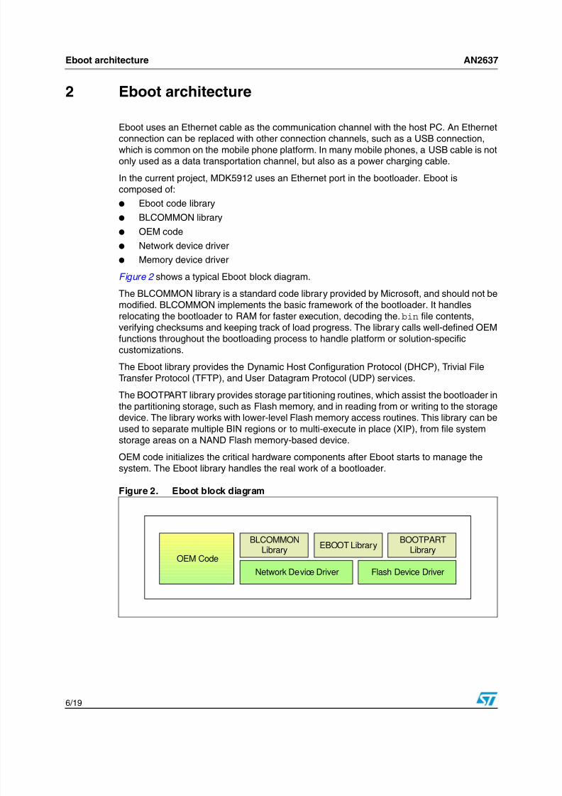
Figure 2 shows a typical Eboot block diagram.The BLCOMMON library is a standard code library provided by Microsoft, and should not bemodified. BLCOMMON implements the basic framework of the bootloader. It handlesrelocating the bootloader to RAM for faster execution, decoding the.bin file contents,verifying checksums and keeping track of load progress. The library calls well-defined OEMfunctions throughout the bootloading process to handle platform or solution-specificcustomizations.
The Eboot library provides the Dynamic Host Configuration Protocol (DHCP), Trivial FileTransfer Protocol (TFTP), and User Datagram Protocol (UDP) services.
The BOOTPART library provides storage partitioning routines, which assist the bootloader inthe partitioning storage, such as Flash memory, and in reading from or writing to the storage
device. The library works with lower-level Flash memory access routines. This library can beused to separate multiple BIN regions or to multi-execute in place (XIP), from file systemstorage areas on a NAND Flash memory-based device.
OEM code initializes the critical hardware components after Eboot starts to manage thesystem. The Eboot library handles the real work of a bootloader.
Figure 2. Eboot block diagram
BLCOMMONLibrary
OEM Code
EBOOT Library
Network Device Driver
BOOTPARTLibrary
Flash Device Driver
8/4/2019 13997
http://slidepdf.com/reader/full/13997 7/19
AN2637 Eboot architecture
7/ 19
In devices based on WINCE versions earlier than 4.0, the OS image is stored in a NORFlash memory, EEPROM or Compact Flash card, from where the image code can executewithout being loaded into RAM. These memories are XIP devices. However, XIP memoriesare usually more expensive compared to NAND Flash memories, which are currently
prominent in consumer electronic devices.To support NAND Flash, Eboot must be enabled with a NAND Flash driver. This driver isprovided as a Flash Media Driver so that the BOOTPART library can operate on NANDFlash.
For more detailed information about Eboot, please refer to the Microsoft Developer Network(MSDN).

8/4/2019 13997
http://slidepdf.com/reader/full/13997 8/19
NAND Flash allocation AN2637
8/ 19
3 NAND Flash allocation
The OS image is stored in the NAND Flash. When Eboot takes over the system, it prepares
the working environment for Windows CE, and prints the optional menu on thehyperterminal. The OS image can be loaded by Eboot.
Eboot can also be stored in NAND memories and loaded by a first boot code. The first bootcode is responsible for initializing the CPU, preparing the RAM, reading Eboot code from theNAND, and handing over the system management rights to Eboot.
In the OMAP5912 development platform, the NAND Flash is a 64-Mbyte small page NANDFlash, and the OS image occupies about 10 Mbytes. Boot-up of the board is performed by acustomized Uboot on the NOR Flash at address 0x0. Eboot is also saved in the NOR Flash.Eboot is called by Uboot with a “go 60000” command. “0x60000” is the start address ofEboot on the NOR Flash.
Figure 3. OMAP5912 platform memory map
Figure 4. OMAP5912 platform memory map if Eboot is saved on NAND
Because the size of the DRAM on the OMAP5912 platform is limited, and to save RAMspace, EBOOT is located in the NOR Flash and executes in place.
The master boot record (MBR) occupies the first page of the NAND Flash. It is a dedicatedpage for partition information used by the Windows CE partition manager. To guarantee theFAT file system works well, the first block is left on purpose for the MBR. The start addressof the data region for the FAT file system should be block-aligned. The regions for the OSimage can have two different cases:
1. The image region in case 1 is raw NAND blocks, and has no BINFS mounted. The OSimage is saved block after block, and bad blocks are ignored. It is suggested that theimage region in this case be reserved behind the data region.
2. The image region in case 2 is BINFS mounted and there are multiple XIP bin files inthis region. BINFS is usually behind the MBR block, with FATFS following.
E B O O T
(FATFS+NFTL)/NFFS for Data
NOR NAND
U B O O T
M B R
OSimage
E B O O T
(FATFS+NFTL)/NFFS for Data
NORNAND
U B O O T
M B R
OSimage

8/4/2019 13997
http://slidepdf.com/reader/full/13997 9/19
AN2637 NAND Flash allocation
9/ 19
With the development of system-on-chip (SOC) technology, more and more processorshave an integrated hardware NAND Flash controller and support booting from NAND Flash.The memory subsystem used for this kind of processor is usually composed of a NANDFlash plus a SDRAM. A portion of NAND is for code storage and the rest is for data storage.
Direct booting from the NAND is usually implemented as follows:
1. After power-on, a small piece of code is automatically loaded by the CPU into theinternal RAM from the first several pages of NAND Flash.
2. This piece of code initializes the platform, prepares the SDRAM, and loads more codefrom the NAND to the SDRAM.
3. The code in the SDRAM takes over the system.
If Windows CE works on this kind of CPU, a small piece of code called “bootstrap code”, issaved in the first several pages of the NAND Flash. Bootstrap code is loaded automaticallyto execute in the internal RAM. Bootstrap code copies Eboot code from the NAND to theSDRAM and hands the system over to Eboot. Eboot prepares the environment for WindowsCE and for loading the OS image from the NAND to the SDRAM.
8/4/2019 13997
http://slidepdf.com/reader/full/13997 10/19
Eboot functionalities AN2637
10/19
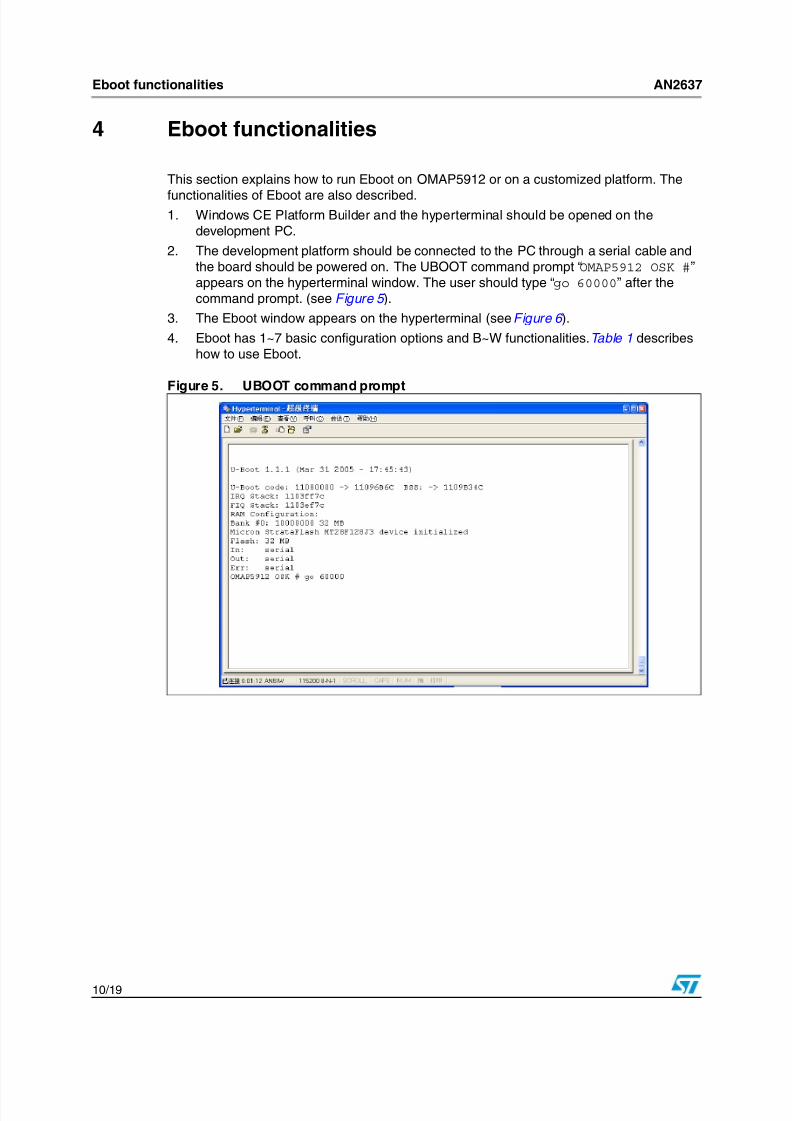
4 Eboot functionalities
This section explains how to run Eboot on OMAP5912 or on a customized platform. The
functionalities of Eboot are also described.1. Windows CE Platform Builder and the hyperterminal should be opened on the
development PC.
2. The development platform should be connected to the PC through a serial cable andthe board should be powered on. The UBOOT command prompt “OMAP5912 OSK #”appears on the hyperterminal window. The user should type “go 60000” after thecommand prompt. (see Figure 5 ).
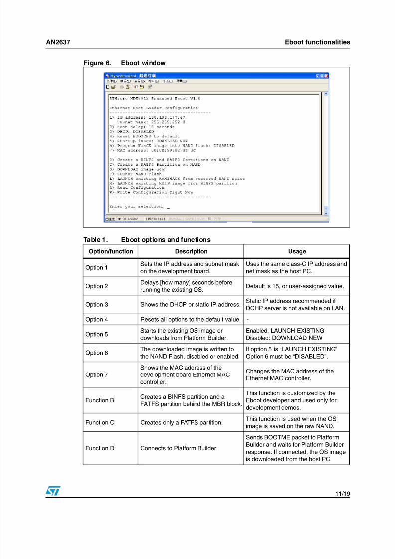
3. The Eboot window appears on the hyperterminal (see Figure 6 ).
4. Eboot has 1~7 basic configuration options and B~W functionalities. Table 1 describeshow to use Eboot.
Figure 5. UBOOT command prompt
8/4/2019 13997
http://slidepdf.com/reader/full/13997 11/19
8/4/2019 13997
http://slidepdf.com/reader/full/13997 12/19
Eboot functionalities AN2637
12/ 19
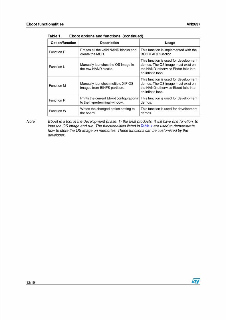
Note: Eboot is a tool in the development phase. In the final products, it will have one function: to load the OS image and run. The functionalities listed in Table 1 are used to demonstrate how to store the OS image on memories. These functions can be customized by the developer.
Function FErases all the valid NAND blocks and
create the MBR.
This function is implemented with the
BOOTPART function
Function LManually launches the OS image in
the raw NAND blocks.
This function is used for development
demos. The OS image must exist on
the NAND, otherwise Eboot falls into
an infinite loop.
Function MManually launches multiple XIP OS
images from BINFS partition.
This function is used for development
demos. The OS image must exist on
the NAND, otherwise Eboot falls into
an infinite loop.
Function RPrints the current Eboot configurations
to the hyperterminal window.
This function is used for development
demos.
Function W
Writes the changed option setting to
the board.
This function is used for development
demos.
Table 1. Eboot options and functions (continued)
Option/function Description Usage

8/4/2019 13997
http://slidepdf.com/reader/full/13997 13/19
AN2637 Storing single binary OS images on a raw NAND
13/ 19
5 Storing single binary OS images on a raw NAND
The OS image on a NAND Flash can not execute in place and must be loaded into the RAM
to run. This means the environment variable IMG_FLASH cannot be set to “1”. In thePlatform Settings window, the option “Enable Image for Flash” should not be selected. Thisoption enables the OS image to execute in place.
Figure 7. Platform settings window
The OS image generated using these options is called RAMIMAGE. The image can onlyexecute if it is loaded into the RAM. RAMIMAGE is also used during the development
process. During the development phase, the RAMIMAGE “nk.bin” is usually downloaded tothe RAM on the target platform from Platform Builder using Eboot.
Before programming the Windows CE RAMIMAGE file to reserved blocks of NAND Flash,
Eboot must mark these blocks BLOCK_STATUS_RESERVED and BLOCK_STATUS_BAD.BLOCK_STATUS_RESERVED is used to distinguish normal bad blocks from reserved badblocks. Deliberately marking the reserved blocks as “bad” means the partition managerdriver does not count these blocks as available for data storage partition. This is a trick usedin the Eboot of Window CE 4.2/5.0.
Theoretically, the location of reserved blocks can be arbitrary. However, to make the dataarea continuous and easy to manage, these blocks are usually reserved in the back part ofthe NAND Flash. If Eboot is saved on the NAND Flash, the blocks accommodating the
Eboot code have the same block status as those for the OS image.Eboot uses two functions to program and read RAMIMAGE to/from the NAND. The twoRAMIMAGE operation functions are called WriteRamImageToBootMedia() andReadRamImageFromBootMedia().
WriteRamImageToBootMedia is called after the RAMIMAGE is downloaded into a RAMcache in the target board if option 5 is “DOWNLOAD NEW” and option 6 is “ENABLED”.
ReadRamImageFromBootMedia is called by choosing the function “L” if option 5 is“LAUNCH EXISTING”. This function reads from the same address whereWriteRamImageToBootMedia programs RAMIMAGE.
8/4/2019 13997
http://slidepdf.com/reader/full/13997 14/19
Storing a multiple region OS image on BINFS AN2637
14/ 19
6 Storing a multiple region OS image on BINFS
Since Windows CE version 4.2, a multiple region OS image can be built with Platform
Builder. A multiple-region OS image contains several BIN files such Nk.bin, Drivers.binand App.bin. The nk.bin contains the OS kernel and critical components for systemrunning. This bin file is loaded tothe RAM and never dumped. The drivers.bin containsdevice drivers. This bin file is loaded into RAM only if the driver in it is required. The
app.bin usually contains some user application programs. It is loaded into the RAM whenone program inside is called and dumped when all the applications inside it end.
A multiple region OS image must be saved in the BINFS partition mounted on a storagemedia. This kind of OS image has the following advantages:
● Independent updates to a single bin file because the modified file only influences itsown bin file.
● Saves more RAM space for key applications because only the required bin files are
loaded into the RAM.● Less power consumption because less a RAM is used.
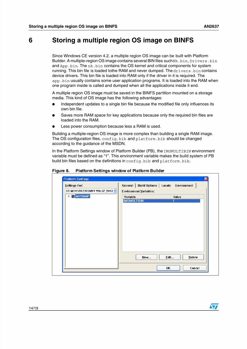
Building a multiple-region OS image is more complex than building a single RAM image.The OS configuration files, config.bib and platform.bib should be changedaccording to the guidance of the MSDN.
In the Platform Settings window of Platform Builder (PB), the IMGMULTIBIN environmentvariable must be defined as “1”. This environment variable makes the build system of PBbuild bin files based on the definitions in config.bib and platform.bib.
Figure 8. Platform Settings window of Platform Builder

8/4/2019 13997
http://slidepdf.com/reader/full/13997 15/19
AN2637 Storing a multiple region OS image on BINFS
15/ 19
The output of a successful multiple-XIP MAKEIMG process produces the following files:
● A .bin file for every XIP region.
● A single .bin file containing all XIP regions, named Xip.bin.
● A .bin file for the XIP chain, named Chain.bin.
● A .nb0 file, if ROMSTART, ROMWIDTH, or ROMSIZE are set in Config.bib. The .nb0 file is a layout of all the .bin files, including Chain.bin, as they should appear in theROM.
Eboot also provides two functions to program/read the multiple region OS image:WriteRegionsToBootMedia() and ReadKernelRegionFromBootMedia().
Before programming the multiple region OS image, the NAND Flash must be formatted withEboot. A MBR record is created on the NAND Flash. It is also suggested to create a BINFSon the NAND Flash. Eboot, implemented for OMAP5912, provides such a utility “B”, whichcan create a BINFS and a FATFS on the NAND. WriteRegionsToBootMedia checks if BINFSis created on the NAND. If no BINFS exists, this function creates a BINFS following the MBRblock, and a FATFS on the remaining available blocks. These two partitions are updated into
the MBR, so that after Windows CE starts working onboard the two partitions can beidentified with Storage Manager in the control panel. ReadKernelRegionFromBootMediareads the kernel region, namely nk.bin, from the BINFS partition by choosing the function“M” if option 5 is “LAUNCH EXISTING”.
8/4/2019 13997
http://slidepdf.com/reader/full/13997 16/19
Summary AN2637
16/ 19
7 Summary
This application note describes how to use Eboot to store a Windows CE OS image into
NAND Flash media. For RAMIMAGE, the nk.bin file is usually saved in the reserved rawNAND blocks, while the multiple region image is normally stored on a BINFS partitioncreated by Eboot. It is recommended to refer to the MSDN web site for related and futherdetailed information as this document only gives a brief outline of how to implement theNAND Flash as the Windows CE image storage medium.

8/4/2019 13997
http://slidepdf.com/reader/full/13997 17/19
AN2637 References
17/ 19
8 References
● Microsoft MSDN and Newsgroup
● Windows CE Practical Development Technology, Dongquan ZHANG, Nanling TAN et al . Publishing House of Electronics Industry, 2006.
● Windows CE.NET Kernel Customization and Application Development , Yulin ZHOU,Yang NING et al . Publishing House of Electronics Industry, 2005.

8/4/2019 13997
http://slidepdf.com/reader/full/13997 18/19
Revision history AN2637
18/ 19
9 Revision history
Table 2. Document revision history
Date Revision Changes
19-Feb-2008 1 Initial release.
8/4/2019 13997
http://slidepdf.com/reader/full/13997 19/19
AN2637
19/ 19
Please Read Carefully:
Information in this document is provided solely in connection with ST products. STMicroelectronics NV and its subsidiaries (“ST”) reserve the
right to make changes, corrections, modifications or improvements, to this document, and the products and services described herein at any
time, without notice.
All ST products are sold pursuant to ST’s terms and conditions of sale.
Purchasers are solely responsible for the choice, selection and use of the ST products and services described herein, and ST assumes no
liability whatsoever relating to the choice, selection or use of the ST products and services described herein.
No license, express or implied, by estoppel or otherwise, to any intellectual property rights is granted under this document. If any part of this
document refers to any third party products or services it shall not be deemed a license grant by ST for the use of such third party products
or services, or any intellectual property contained therein or considered as a warranty covering the use in any manner whatsoever of such
third party products or services or any intellectual property contained therein.
UNLESS OTHERWISE SET FORTH IN ST’S TERMS AND CONDITIONS OF SALE ST DISCLAIMS ANY EXPRESS OR IMPLIED
WARRANTY WITH RESPECT TO THE USE AND/OR SALE OF ST PRODUCTS INCLUDING WITHOUT LIMITATION IMPLIED
WARRANTIES OF MERCHANTABILITY, FITNESS FOR A PARTICULAR PURPOSE (AND THEIR EQUIVALENTS UNDER THE LAWS
OF ANY JURISDICTION), OR INFRINGEMENT OF ANY PATENT, COPYRIGHT OR OTHER INTELLECTUAL PROPERTY RIGHT.
UNLESS EXPRESSLY APPROVED IN WRITING BY AN AUTHORIZED ST REPRESENTATIVE, ST PRODUCTS ARE NOT
RECOMMENDED, AUTHORIZED OR WARRANTED FOR USE IN MILITARY, AIR CRAFT, SPACE, LIFE SAVING, OR LIFE SUSTAINING
APPLICATIONS, NOR IN PRODUCTS OR SYSTEMS WHERE FAILURE OR MALFUNCTION MAY RESULT IN PERSONAL INJURY,
DEATH, OR SEVERE PROPERTY OR ENVIRONMENTAL DAMAGE. ST PRODUCTS WHICH ARE NOT SPECIFIED AS "AUTOMOTIVE
GRADE" MAY ONLY BE USED IN AUTOMOTIVE APPLICATIONS AT USER’S OWN RISK.
Resale of ST products with provisions different from the statements and/or technical features set forth in this document shall immediately void
any warranty granted by ST for the ST product or service described herein and shall not create or extend in any manner whatsoever, any
liability of ST.
ST and the ST logo are trademarks or registered trademarks of ST in various countries.
Information in this document supersedes and replaces all information previously supplied.
The ST logo is a registered trademark of STMicroelectronics. All other names are the property of their respective owners.
© 2008 STMicroelectronics - All rights reserved
STMicroelectronics group of companies
Australia - Belgium - Brazil - Canada - China - Czech Republic - Finland - France - Germany - Hong Kong - India - Israel - Italy - Japan -
Malaysia - Malta - Morocco - Singapore - Spain - Sweden - Switzerland - United Kingdom - United States of America
www.st.com