wt61c digital ahrs sensor specification · 2019-09-11 · wt61c digital ahrs sensor specification...
TRANSCRIPT

https://wiki.wit-motion.com/english
WhatsApp:+86 13652339539 E-mail:[email protected] Web:https://wiki.wit-motion.com/english- 1 -
WT61C Digital AHRS Sensor
SPECIFICATION
Model : WT61C
Description :6 Axis Digital Attitude Angle Sensor With Case
Quality control system standard: ISO9001:2016
Tilt switch production standard:GB/T191SJ 20873-2016
Criterion of detection:GB/T191SJ 20873-2016
Revision date:2019.09.09
Download Link(software, manual, etc.):
https://drive.google.com/file/d/1o-bcjaoml6dNeXbMDcYy7-0kfL0J1B3A

https://wiki.wit-motion.com/english
WhatsApp:+86 13652339539 E-mail:[email protected] Web:https://wiki.wit-motion.com/english- 2 -
Catalog
1 Description...................................................................................................- 3 -
2 Product parameters...................................................................................... - 4 -
3 Product display............................................................................................ - 5 -
4 Axial direction............................................................................................. - 5 -
5 Connection...................................................................................................- 6 -
5.1 Serial connection...............................................................................- 6 -
5.2 calibration(calibration on PC software).......................................... - 11 -
5.2.1 Z-axis to 0................................................................................- 11 -
5.2.2 Accelerometer calibration....................................................... - 12 -
5.3 Data recording.................................................................................- 12 -
5.4 Installation direction........................................................................- 13 -
5.5 Dormancy and break dormancy...................................................... - 15 -
5.6 Static threshold and measure width.................................................- 15 -
5.7 Connect to Phone............................................................................ - 17 -
6 Communication protocol........................................................................... - 22 -
6.1 PC software to module.................................................................... - 22 -
6.2 Module to PC software....................................................................- 22 -
6.2.1 Acceleration output................................................................. - 23 -
6.2.2 Angular velocity output...........................................................- 23 -
6.2.3 Angle output............................................................................- 24 -
6.3 Date analysis and sample code........................................................- 25 -
6.4 Data analysis sample in embedded environment............................ - 26 -
7 Application area.........................................................................................- 29 -

https://wiki.wit-motion.com/english
WhatsApp:+86 13652339539 E-mail:[email protected] Web:https://wiki.wit-motion.com/english- 3 -
1 Description The purpose of this six axis gyro acceleration module uses high precision MPU6050
module, measuring data by the processor reads the MPU6050 and then output through the
serial port, and elaborate PCB layout and process to ensure that the MPU6050 received the
minimum interference with the highest measurement accuracy.
An internal voltage stabilizing circuit module, voltage 3.3v~5v, pin compatible with the
3.3V/5V embedded system, convenient connection.
The advanced digital filtering technology of this product can effectively reduce the
measurement noise and improve the measurement accuracy.
Integrates gesture solver, with dynamic Kalman filter algorithm, can get the accurate
attitude in dynamic environment, attitude measurement precision is up to 0.05 degrees
with high stability, performance is even better than some professional inclinometer.
Note: This module does not contain magnetometer, can not be tested with the yaw angle,
so yaw angle is calculated by integration, it will drift, the yaw angle is accurate only in a
short time. The X, Y axis angle is accurate because it can be filtered by gravity field, it will not
drift.

https://wiki.wit-motion.com/english
WhatsApp:+86 13652339539 E-mail:[email protected] Web:https://wiki.wit-motion.com/english- 4 -
2 Product parameters
1) Voltage: 3.3V-5V
2) Current: <40mA
3) Size : 51.3mm x 36mm X 15mm
4) Measuring dimensions: Acceleration:3D Angular Velocity: 3D Attitude
Angle:2D(Roll Pitch)
5) Range : Acceleration : ±16g Angular Velocity : ±2000°/s Angle: (X±180°,Y±
90°)
6) Resolution: Acceleration:0.0005g , Angular velocity: 0.61°/s.
7) Stability: Acceleration : 0.01g Angular Velocity : 0.05°/s
8) Attitude measurement stability: 0.01°
9) Output content: Time, Acceleration , Angular Velocity ,Tilt Angle
10) Data output frequency:100Hz(baudrate115200)/20Hz(9600baud).
11) Data interface: Serial port(TTL/RS232).
12)Baud rate: 9600,115200(default).

https://wiki.wit-motion.com/english
WhatsApp:+86 13652339539 E-mail:[email protected] Web:https://wiki.wit-motion.com/english- 5 -
3 Product display
4 Axial direction
As shown in figure above, The axis of the module is in the upper picture, upward
for x-axis, to the left for y-axis, Perpendicular to the paper, outward to the z-axis,
The direction of rotation is defined by the Law of the right hand. That is to say the
direction of four-fingers bending is the direction of rotation around the axis. The
thumb of the right hand points to axis.

https://wiki.wit-motion.com/english
WhatsApp:+86 13652339539 E-mail:[email protected] Web:https://wiki.wit-motion.com/english- 6 -
5 Connection
5.1Serial connection
Module 3 in 1 Convert:
Driver installation:
First, install the driver CH340 when we used the USB serial module ,after installed
the driver. then get the corresponding Com number in the device manager. Driver
as followed:
https://wiki.wit-motion.com/english/doku.php?id=communication_module
https://wiki.wit-motion.com/english
WhatsApp:+86 13652339539 E-mail:[email protected] Web:https://wiki.wit-motion.com/english- 7 -
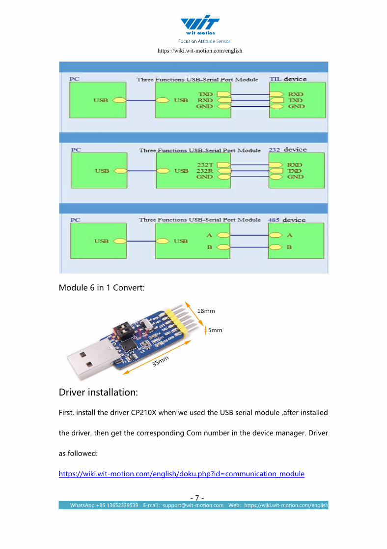
Module 6 in 1 Convert:
Driver installation:
First, install the driver CP210X when we used the USB serial module ,after installed
the driver. then get the corresponding Com number in the device manager. Driver
as followed:
https://wiki.wit-motion.com/english/doku.php?id=communication_module
https://wiki.wit-motion.com/english
WhatsApp:+86 13652339539 E-mail:[email protected] Web:https://wiki.wit-motion.com/english- 8 -
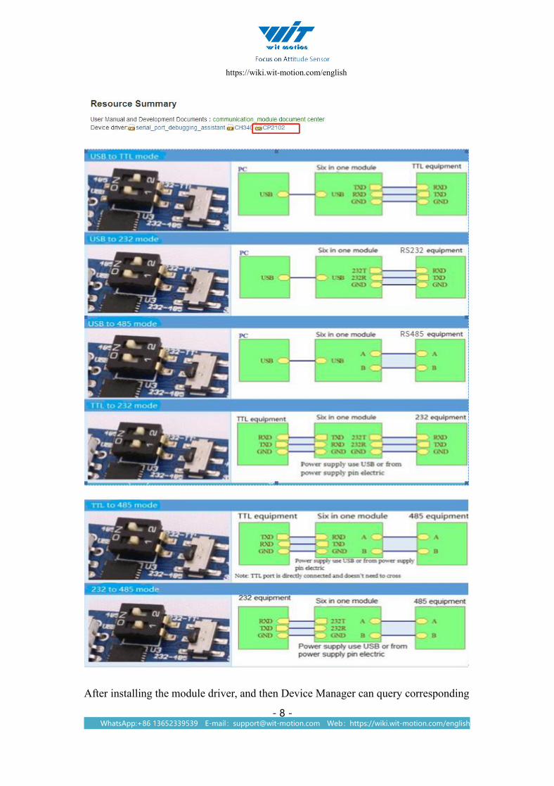
After installing the module driver, and then Device Manager can query corresponding

https://wiki.wit-motion.com/english
WhatsApp:+86 13652339539 E-mail:[email protected] Web:https://wiki.wit-motion.com/english- 9 -
serial number, as below figure shows:
Connect with PC software
Open the software “MiniIMU.exe” and select the Com number
which you have got in the device manager before.
Click the menu “Type” , Select the model as “JY61” in the software.

https://wiki.wit-motion.com/english
WhatsApp:+86 13652339539 E-mail:[email protected] Web:https://wiki.wit-motion.com/english- 10 -
Click the menu “Baud ”in the software and then select 115200, then the software
will show the data.

https://wiki.wit-motion.com/english
WhatsApp:+86 13652339539 E-mail:[email protected] Web:https://wiki.wit-motion.com/english- 11 -
5.2calibration(calibration on PC software)
5.2.1 Z-axis to 0
The module should be calibrated before you use it. The module calibrate includes
Z-axis to 0 ,Accelerometer calibration.
The z axis is 0 is the module z axis angle initial state is relative 0 degree angle
When the module is used before and z - axis drift is large, the z - axis can be
calibrated
https://wiki.wit-motion.com/english
WhatsApp:+86 13652339539 E-mail:[email protected] Web:https://wiki.wit-motion.com/english- 12 -
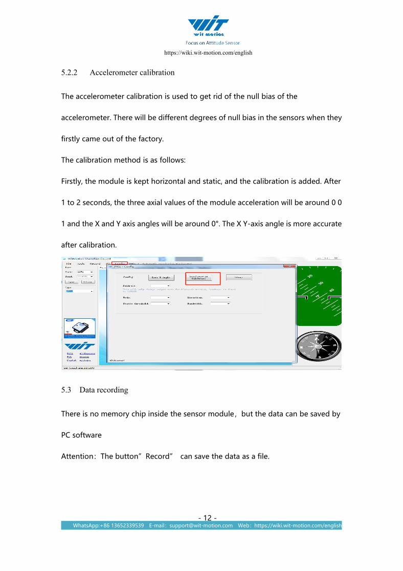
5.2.2 Accelerometer calibration
The accelerometer calibration is used to get rid of the null bias of the
accelerometer. There will be different degrees of null bias in the sensors when they
firstly came out of the factory.
The calibration method is as follows:
Firstly, the module is kept horizontal and static, and the calibration is added. After
1 to 2 seconds, the three axial values of the module acceleration will be around 0 0
1 and the X and Y axis angles will be around 0°. The X Y-axis angle is more accurate
after calibration.
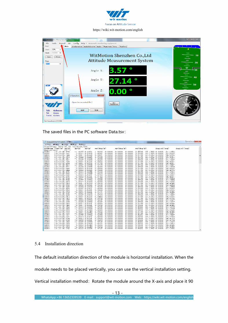
5.3 Data recording
There is no memory chip inside the sensor module,but the data can be saved by
PC software
Attention:The button”Record” can save the data as a file.
https://wiki.wit-motion.com/english
WhatsApp:+86 13652339539 E-mail:[email protected] Web:https://wiki.wit-motion.com/english- 13 -
The saved files in the PC software Data.tsv:
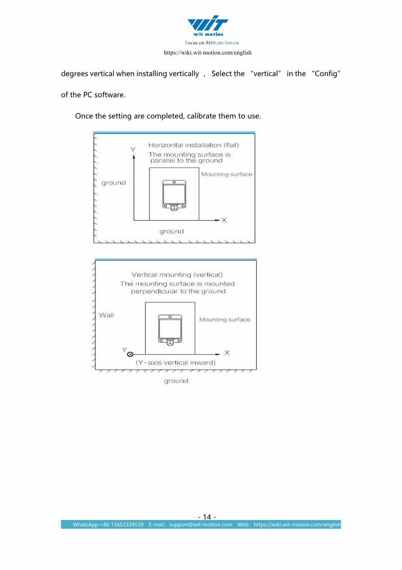
5.4 Installation direction
The default installation direction of the module is horizontal installation. When the
module needs to be placed vertically, you can use the vertical installation setting.
Vertical installation method:Rotate the module around the X-axis and place it 90
https://wiki.wit-motion.com/english
WhatsApp:+86 13652339539 E-mail:[email protected] Web:https://wiki.wit-motion.com/english- 14 -
degrees vertical when installing vertically , Select the “vertical” in the “Config”
of the PC software.
Once the setting are completed, calibrate them to use.

https://wiki.wit-motion.com/english
WhatsApp:+86 13652339539 E-mail:[email protected] Web:https://wiki.wit-motion.com/english- 15 -
5.5 Dormancy and break dormancy
Dormancy:The module pauses working and enters the standby state, dormancy
can reduce power consumption.
Break dormancy:The module enters the working state from the standby state.
How to use:The default state of the module is working state,Click “Sleep”in the
“config”of the PC software to enter the standby state, click “Sleep” again the
module will break the dormancy.
5.6 Static threshold and measure width
Static threshold : The angular velocity of the gyroscope chip is slightly change
when the module is in static placement. The effect of the “Static threshold” is
When the angular velocity is less than the threshold module output angular
velocity is 0.

https://wiki.wit-motion.com/english
WhatsApp:+86 13652339539 E-mail:[email protected] Web:https://wiki.wit-motion.com/english- 16 -
Bandwidth : The module output the data within the measurement bandwidth.
Data greater than bandwidth is automatically filtered out.
How to use:Click the “Bandwidth ”of the “config ” in the PC software. default
is 10 HZ.
https://wiki.wit-motion.com/english
WhatsApp:+86 13652339539 E-mail:[email protected] Web:https://wiki.wit-motion.com/english- 17 -
PS: The default setting of Static threshold and bandwidth works in most case. you
should not set it any more.
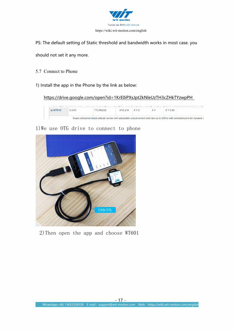
5.7 Connect to Phone
1) Install the app in the Phone by the link as below:
https://drive.google.com/open?id=1KrE0iPXsJpt2kNleUzTH3cZHkTYzwpPH
1)We use OTG drive to connect to phone
2)Then open the app and choose WT601

https://wiki.wit-motion.com/english
WhatsApp:+86 13652339539 E-mail:[email protected] Web:https://wiki.wit-motion.com/english- 18 -
3) choose 115200
https://wiki.wit-motion.com/english
WhatsApp:+86 13652339539 E-mail:[email protected] Web:https://wiki.wit-motion.com/english- 19 -
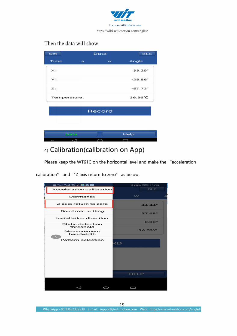
Then the data will show
4) Calibration(calibration on App)
Please keep the WT61C on the horizontal level and make the “acceleration
calibration” and “Z axis return to zero” as below:

https://wiki.wit-motion.com/english
WhatsApp:+86 13652339539 E-mail:[email protected] Web:https://wiki.wit-motion.com/english- 20 -
1) Accelerometer Calibration
The accelerometer calibration is used to remove the zero bias of the
accelerometer. When the sensor is out of the factory, there will be different
degrees of bias error. After manual calibration, the measurement will be
accurate.
1、Methods as below: Firstly keep the module horizontally stationary, click
“Acceleration”, after 1~2s the acceleration X Y Z value will at 0 0 1. X Y angle:
0°.After calibration the value will be accurate.
2) Z axis return to zero
Just click the z axis return to zero, then the data will show.

https://wiki.wit-motion.com/english
WhatsApp:+86 13652339539 E-mail:[email protected] Web:https://wiki.wit-motion.com/english- 21 -
https://wiki.wit-motion.com/english
WhatsApp:+86 13652339539 E-mail:[email protected] Web:https://wiki.wit-motion.com/english- 22 -
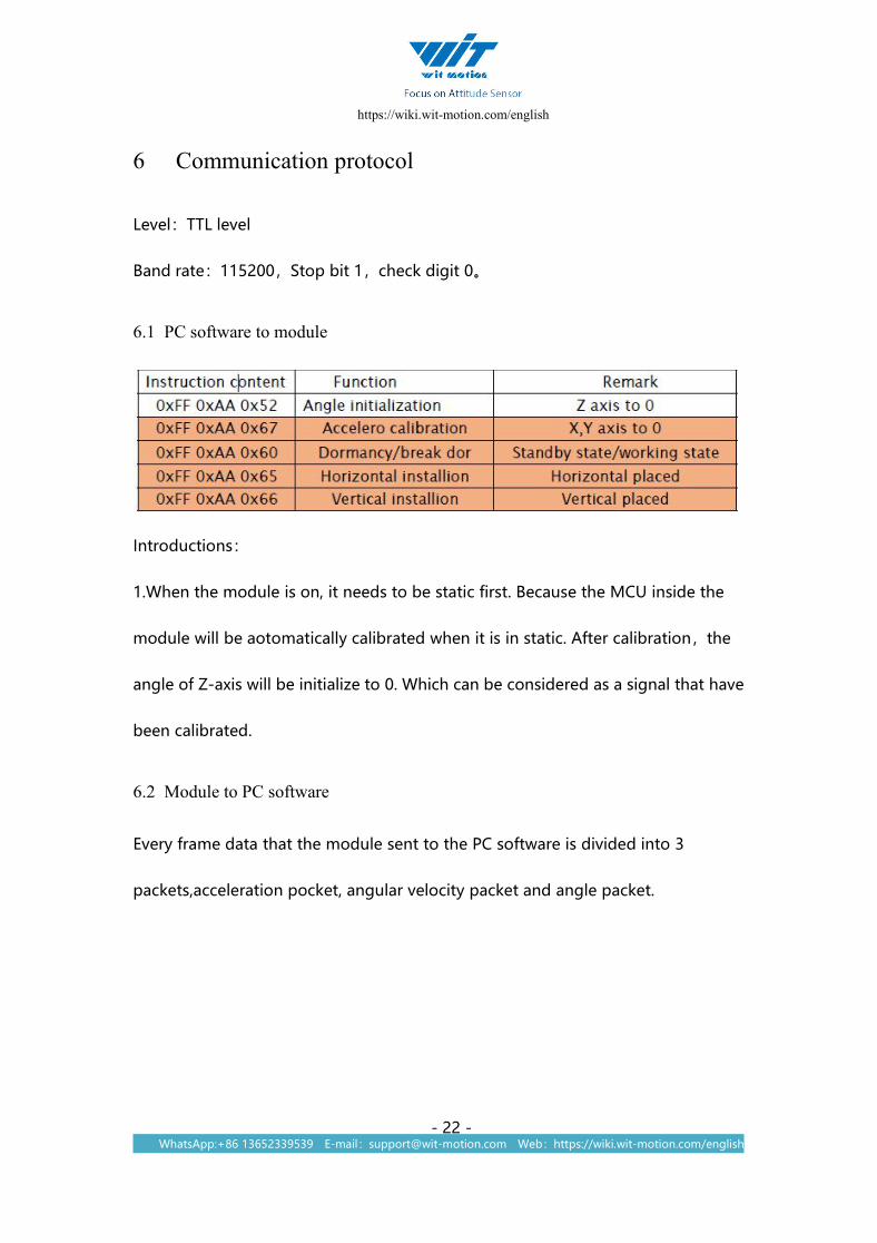
6 Communication protocol
Level:TTL level
Band rate:115200,Stop bit 1,check digit 0。
6.1 PC software to module
Introductions:
1.When the module is on, it needs to be static first. Because the MCU inside the
module will be aotomatically calibrated when it is in static. After calibration,the
angle of Z-axis will be initialize to 0. Which can be considered as a signal that have
been calibrated.
6.2 Module to PC software
Every frame data that the module sent to the PC software is divided into 3
packets,acceleration pocket, angular velocity packet and angle packet.

https://wiki.wit-motion.com/english
WhatsApp:+86 13652339539 E-mail:[email protected] Web:https://wiki.wit-motion.com/english- 23 -
6.2.1 Acceleration output
Formula for calculating acceleration:
ax=((AxH<<8)|AxL)/32768*16g(g is gvality acceleration,9.8m/s2)
ay=((AyH<<8)|AyL)/32768*16g(g is gvality acceleration,9.8m/s2)
az=((AzH<<8)|AzL)/32768*16g(g is gvality acceleration,9.8m/s2)
Formula for calculating temperature:
T=((TH<<8)|TL) /340+36.53 ℃
Checksum:
Sum=0x55+0x51+AxH+AxL+AyH+AyL+AzH+AzL+TH+TL
6.2.2 Angular velocity output
https://wiki.wit-motion.com/english
WhatsApp:+86 13652339539 E-mail:[email protected] Web:https://wiki.wit-motion.com/english- 24 -
Formula for calculating angular velocity:
wx=((wxH<<8)|wxL)/32768*2000(°/s)
wy=((wyH<<8)|wyL)/32768*2000(°/s)
wz=((wzH<<8)|wzL)/32768*2000(°/s)
Formula for calculating temperature:
T=((TH<<8)|TL) /340+36.53 ℃
Checksum:
Sum=0x55+0x52+wxH+wxL+wyH+wyL+wzH+wzL+TH+TL
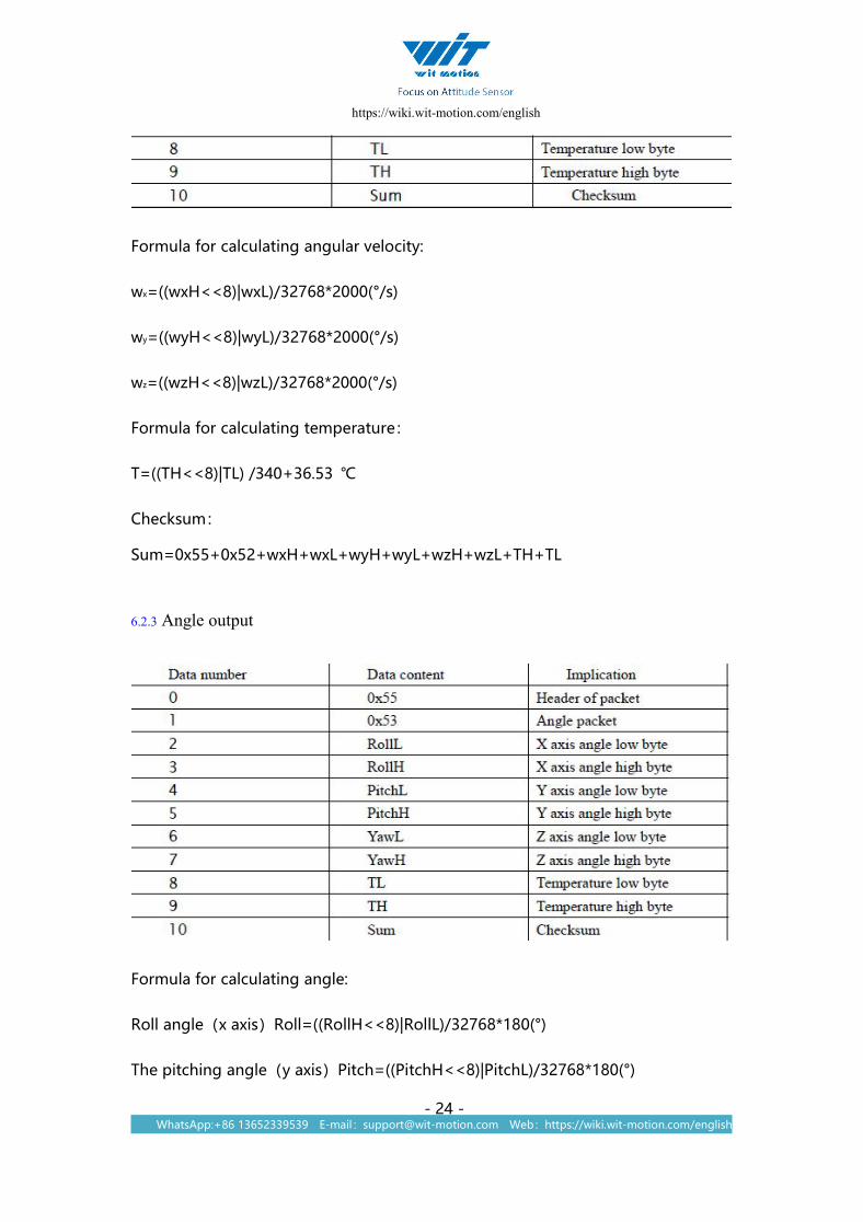
6.2.3 Angle output
Formula for calculating angle:
Roll angle(x axis)Roll=((RollH<<8)|RollL)/32768*180(°)
The pitching angle(y axis)Pitch=((PitchH<<8)|PitchL)/32768*180(°)

https://wiki.wit-motion.com/english
WhatsApp:+86 13652339539 E-mail:[email protected] Web:https://wiki.wit-motion.com/english- 25 -
Yaw angle(zaxis)Yaw=((YawH<<8)|YawL)/32768*180(°)
Formula for calculating temperature:
T=((TH<<8)|TL) /340+36.53 ℃
Checksum:
Sum=0x55+0x53+RollH+RollL+PitchH+PitchL+YawH+YawL+TH+TL
Attention:
1. The coordinate system used in the calculation of attitude angle is the northeast
coordinatesystem , Place the module positivly, left is X-axis, front is X-axis.
upward is Z-axis.When the attitude is expressed by the Euler angle. Coordinate
rotation sequence is Z-Y-X.
6.3 Date analysis and sample code
double a[3],w[3],Angle[3],T;
void DecodeIMUData(unsigned char chrTemp[])
{
switch(chrTemp[1])
{
case 0x51:
a[0] = (short(chrTemp[3]<<8|chrTemp[2]))/32768.0*16;
a[1] = (short(chrTemp[5]<<8|chrTemp[4]))/32768.0*16;
a[2] = (short(chrTemp[7]<<8|chrTemp[6]))/32768.0*16;
T = (short(chrTemp[9]<<8|chrTemp[8]))/340.0+36.25;
break;
case 0x52:
w[0] = (short(chrTemp[3]<<8|chrTemp[2]))/32768.0*2000;
w[1] = (short(chrTemp[5]<<8|chrTemp[4]))/32768.0*2000;
w[2] = (short(chrTemp[7]<<8|chrTemp[6]))/32768.0*2000;
T = (short(chrTemp[9]<<8|chrTemp[8]))/340.0+36.25;
break;
case 0x53:
https://wiki.wit-motion.com/english
WhatsApp:+86 13652339539 E-mail:[email protected] Web:https://wiki.wit-motion.com/english- 26 -
Angle[0] = (short(chrTemp[3]<<8|chrTemp[2]))/32768.0*180;
Angle[1] = (short(chrTemp[5]<<8|chrTemp[4]))/32768.0*180;
Angle[2] = (short(chrTemp[7]<<8|chrTemp[6]))/32768.0*180;
T = (short(chrTemp[9]<<8|chrTemp[8]))/340.0+36.25;
printf("a = %4.3f\t%4.3f\t%4.3f\t\r\n",a[0],a[1],a[2]);
printf("w = %4.3f\t%4.3f\t%4.3f\t\r\n",w[0],w[1],w[2]);
printf("Angle = %4.2f\t%4.2f\t%4.2f\tT=%4.2f\r\n",Angle[0],Angle[1],Angle[2],T);
break;
}
}
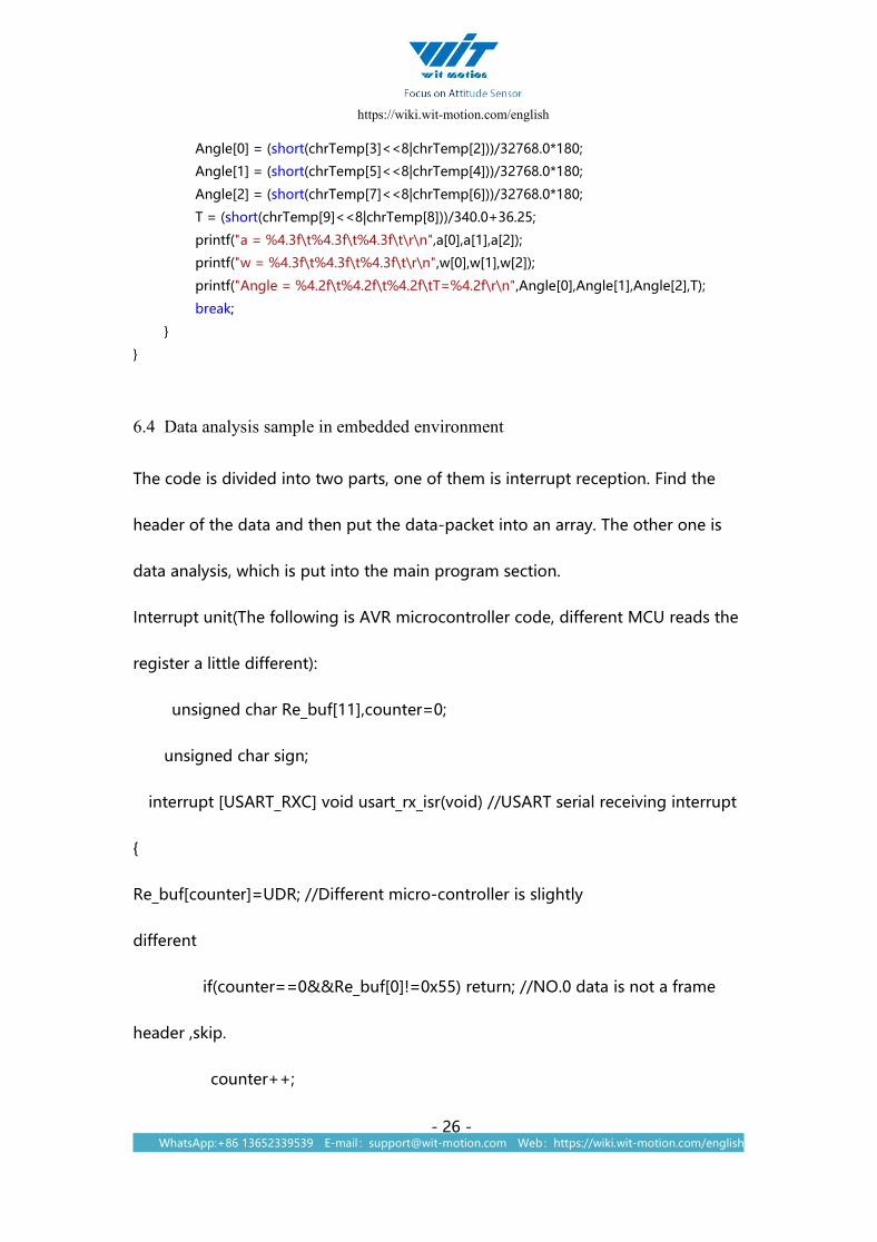
6.4 Data analysis sample in embedded environment
The code is divided into two parts, one of them is interrupt reception. Find the
header of the data and then put the data-packet into an array. The other one is
data analysis, which is put into the main program section.
Interrupt unit(The following is AVR microcontroller code, different MCU reads the
register a little different):
unsigned char Re_buf[11],counter=0;
unsigned char sign;
interrupt [USART_RXC] void usart_rx_isr(void) //USART serial receiving interrupt
{
Re_buf[counter]=UDR; //Different micro-controller is slightly
different
if(counter==0&&Re_buf[0]!=0x55) return; //NO.0 data is not a frame
header ,skip.
counter++;

https://wiki.wit-motion.com/english
WhatsApp:+86 13652339539 E-mail:[email protected] Web:https://wiki.wit-motion.com/english- 27 -
if(counter==11) //11 data has been received
{ counter=0; // Reassigned,ready for the next frame data reception
sign=1;
}
}
Main program section:
float a[3],w[3],angle[3],T;
extern unsigned char Re_buf[11],counter;
extern unsigned char sign;
while(1)
{
if(sign)
{
sign=0;
if(Re_buf[0]==0x55) //Check the frame header
{
switch(Re_buf [1])
{c
ase 0x51:
a[0] = (short(Re_buf [3]<<8| Re_buf [2]))/32768.0*16;
a[1] = (short(Re_buf [5]<<8| Re_buf [4]))/32768.0*16;

https://wiki.wit-motion.com/english
WhatsApp:+86 13652339539 E-mail:[email protected] Web:https://wiki.wit-motion.com/english- 28 -
a[2] = (short(Re_buf [7]<<8| Re_buf [6]))/32768.0*16;
T = (short(Re_buf [9]<<8| Re_buf [8]))/340.0+36.25;
break;
case 0x52:
w[0] = (short(Re_buf [3]<<8| Re_buf [2]))/32768.0*2000;
w[1] = (short(Re_buf [5]<<8| Re_buf [4]))/32768.0*2000;
w[2] = (short(Re_buf [7]<<8| Re_buf [6]))/32768.0*2000;
T = (short(Re_buf [9]<<8| Re_buf [8]))/340.0+36.25;
break;
case 0x53:
angle[0] = (short(Re_buf [3]<<8| Re_buf [2]))/32768.0*180;
angle[1] = (short(Re_buf [5]<<8| Re_buf [4]))/32768.0*180;
angle[2] = (short(Re_buf [7]<<8| Re_buf [6]))/32768.0*180;
T = (short(Re_buf [9]<<8| Re_buf [8]))/340.0+36.25;
break;
}
}
}

https://wiki.wit-motion.com/english
WhatsApp:+86 13652339539 E-mail:[email protected] Web:https://wiki.wit-motion.com/english- 29 -
7 Application area
Agricultural machinery Internet of things
Solar energy Power monitoring
Medical instruments Construction machinery
Geological monitoring

https://wiki.wit-motion.com/english
WhatsApp:+86 13652339539 E-mail:[email protected] Web:https://wiki.wit-motion.com/english- 30 -
WitMotion ShenZhen Co., Ltd
WT61C High Precision Digital Inclinometer
Contact: Mr. Kyle Tsang
E-mail : [email protected]
Skype: live:kyle_8394
WhatsApp: +86 136 523 39539
Amazon in USA: www.amazon.com/witmotion
Amazon in Canada: www.amazon.ca/witmotion
Amazon in Japan: www.amazon.co.jp/witmotion
Official Direct Store: www.aliexpress.com/store/4709011
Address : Honghai building 1405 Songgang town Baoan District
Shenzhen Guangdong Province China