wsprlite power conditioner - sotabeams · page 1 power conditioner 12 june 2017 wsprlite power...
TRANSCRIPT

Page 1 Power Conditioner 12 June 2017
WSPRlite Power Conditioner
a Powerpole Power Conditioner for your WSPRlite
Ideal for running your WSPRlite from a battery supply or "wall-wart", the WSPRlite Power Conditioner converts any 7 - 20 Volt DC supply into a super-clean quiet 5 Volt USB supply - perfect for your WSPRlite.
We use a linear regulator to avoid the noise problems so often associated with cheap switching regulators. Rated at 200 mA and with a re-settable fuse, the Power Conditioner will keep your WSPRlite happy - and safe too. The DC input is protected against voltage spikes by a special TVS diode and is provided with additional smoothing with a low-esr input capacitor. These features have been added in case you wish to use your WSPRlite in a mobile setting. Unlike simple chargers, we also condition the data lines to avoid unwanted noise affecting your WSPRlite.
Building the Power Conditioner is easy and fun. It will take
about 30 minutes to build and is suitable for a beginner.

Page 2 Power Conditioner 12 June 2017
Revison History 10-Jan-17 First issued
23-Jan-17 Added reference to polyfuse.
6-June-17 Update for pcb V2.0
12-June-17 Minor improvements (customer suggestions)
POWER CONDITIONER Packing List It’s a good idea to check that you have all the parts before you get started:
Designator VALUE NOTES
C1, C2 10uF Yellow tantalum bead capacitors 10-25V
R1, R2 15k 15k Ohm resistors brown green orange
R3* 220 220 Ohm resistor red brown
D1 Transient suppression diode Black with silver end
D2 LED 3mm
F1 Polyfuse Yellow RX20F
J1 USB socket U1 5 Volt IC voltage regulator
Heatsink black finned metal
J2 part red Powerpole connector shell J2 part black Powerpole connector shell J2 part Powerpole connector contacts x2 Special PCB contacts
J3* Optional 2.1mm power connector Not suitable for use with enclosure kit
PCB
*=suppied with V2.0 pcb kit only
Item Number Comments
ENCLOSURE KIT
Laser cut front panel 1
Black plastic box 1
Nylon hex spacers 6
Nylon screws 6
Nylon nuts 6
Aluminium foil (self adhesive) 1 to put in the bottom of the box
If anything is missing, just get in touch for help.
POWER CONDITIONER Instructions The POWER CONDITIONER kit is easy to make and you will end up with really useful addition to your
portable station.

Page 3 Power Conditioner 12 June 2017
Step by step instructions together with photographs will make it easy to build your Power
Conditioner. It will take around 30 minutes of work.
Spotted a mistake or need help? Please let me know!
Email [email protected], telephone +44 (0) 7976 688359
Building tips Use a soldering iron with a fine tip (e.g. 1.2mm) and a fine solder (e.g. 0.7mm).
All the components except U1 and its heatsink are installed on the top side of the board labelled
“SOTABEAMS”.
Use the list above to identify the components.
Only solder a component when you are sure that you have inserted the correct one.

Page 4 Power Conditioner 12 June 2017
Assembly NOTE: PCB version V2.0 is supplied with two different power input connectors The black 2.1mm
socket is only to be used if you are not intending to use our enclosure kit. If you are using this
connector, skip instruction 1, 2 and 3. If you are using Powerpoles (recommended), start at
instruction 1.
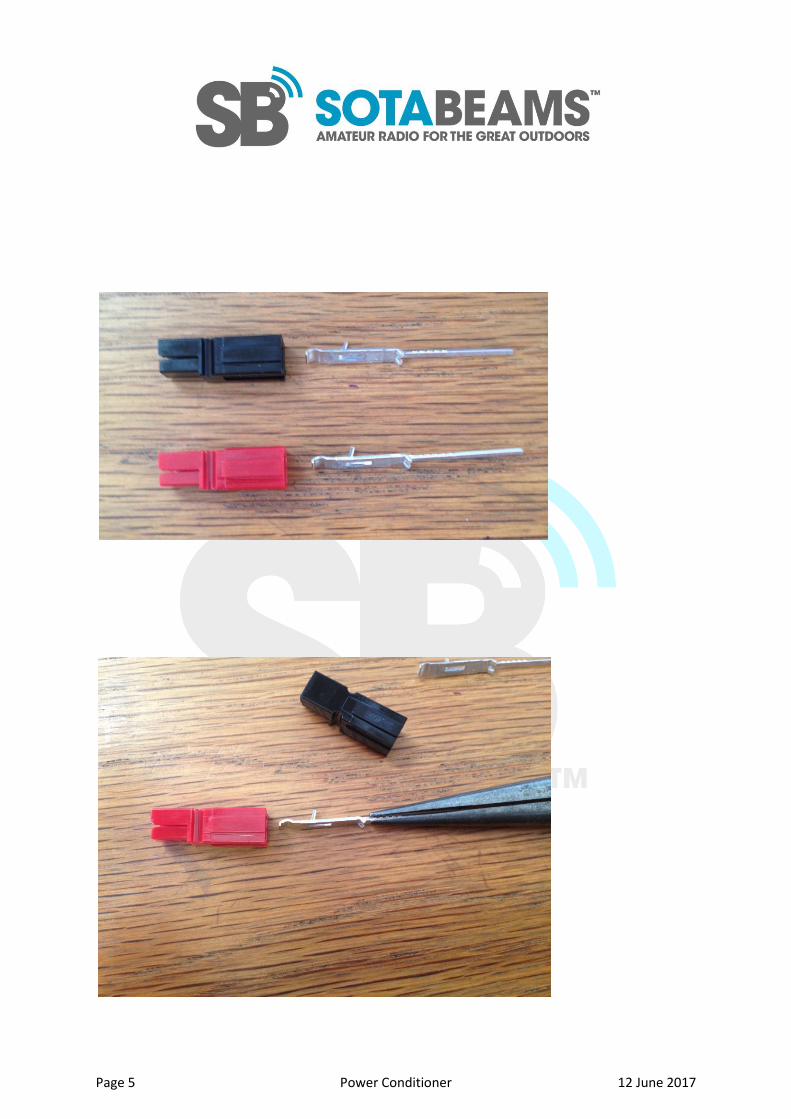
1. Slide the pins into the plug shells. This is best done with pliers. They click into place when seated
correctly. Note that they only go in one way – see photo. The tongue of the metal contact slides to
the front on the shell clipping over the metal slide in the shell. When correctly assembled, the post
extends 20mm from the back of the shell.
The diagram above is for the standard Powerpole contacts. The cutway shows how the contact
should sit when clicked home properly
Page 5 Power Conditioner 12 June 2017

Page 6 Power Conditioner 12 June 2017
2. Pair up, the shells as shown, one black and one red. The shells will pair up in many ways so make
sure that you get them right – as shown in the photograph. This is the “standard way” of using
Powerpole connectors for ham radio use.
3. Install the connector on the top surface of the board with the red shell against + symbol.
4. Install R1 and R2. They can be sat slightly above the board to ease their installation.
5. PCB V2.0 only: Install R3
6. Install D1 with the silver band as indicated on the silk screening.
7. Install C1. The + lead goes into the square pad.
8. Install C2. The + lead goes into the square pad.

Page 7 Power Conditioner 12 June 2017
9. Install fuse F1. This can go in either way round.
10. Install U1 on the underside of the board as shown.
11. Slide the heat-sink onto U1. It should fit tightly. If it does not, remove it, bend the tab on the
heat sink down and try again.
12. If you have not purchased the enclosure kit, install the USB connector. If you have purchased the
enclosure kit, leave the installtion until after you have completed the enclose installation.
13. If you are not using the enclosure kit, install the LED, D2. The short lead of the LED goes through
the square pad. If you are using our enclose kit, poke the LED through the holes but do not solder it.

Page 8 Power Conditioner 12 June 2017
PCB V1.0
Testing This is a good time to test the PCB.
First perform a detailed visual inspection of the PCB. Check that all the connections are soldered
properly and that the pins of U1 are properly soldered with no bridges.
Apply a fused/current limited 12 Volt supply to the Powerpole connector.
On the top side of the board, carefully check the voltages on the pins of U1. On the top side of the
board (the one with the writing on it) the right-hand pin should have 12 Volts on it. The middle pin, 0
Volts and the left-hand pin 5 Volts (+/- 0.1 Volts).
Next check the Voltages on the holes where the USB connector will be installed – do not install it
yet!
On the hole with the square pad (left-hand side) 5 Volts (+/- 0.1 Volts)
Right-hand pin 0 Volts.

Page 9 Power Conditioner 12 June 2017
Mounting Instructions Insert the six nylon hex spacers into the PCB so that the screw thread is on the underside of the PCB.
Screw the nylon nuts onto the spacers – do not over-tighten.
Attach the PCB to the laser cut panel using the six screws – do not over-tighten.
PCB V2.0 only: Push the LED up so that it sits in the hole on the front panel, solder in position on the
PCB.
Bend the mounting lugs on the USB socket inwards slightly and insert it through the slot on the front
panel. Open out the lugs and carefully push it so that he lugs and pins go through the PCB. It should
be a perfect fit. If it does not fit, you have probably put it in the wrong way round!
Cut the self adhesive aluminium sheet and stick it in the bottom of the box. This acts as a heat
spreader for the heatsink.
Insert the Power Conditioner Mini unit so that the heatsink sits over the aluminium sheet. Screw
down with the screws provided in the box.
The four black circular blanking parts are not needed.
Fault finding
The most likely problem on this board is a poor solder joint, Inspect your soldering
carefully.
If you get stuck, send me an e-mail for help! [email protected]