wsb 4 software tutorial - maguire · turning power off in the middle of a batch might cause one...
TRANSCRIPT

WEIGH SCALE BLENDER WITH
“FOUR” COMPONENT SOFTWARE
OCTOBER 24, 2012
TUTORIAL MANUAL
Maguire Products Inc Maguire Products Inc Maguire Products Inc Maguire Products Inc Maguire Products Inc Maguire Products Inc Maguire Products Inc Eleven Crozerville Road Aston, PA. 610 459 4300
Tutorial Manual Tutorial Manual Tutorial Manual Tutorial Manual Tutorial Manual
© COPYRIGHT MAGUIRE PRODUCTS, INC. 2012

2

3
Table of Contents
SAFETY HAZARDS__________________________________________________ 4
Safety Features__________________________________________________________________4
EC Declaration of Conformity_____________________________________________________5
EC Declaration of Conformity_____________________________________________________5
Blender Parts Key _______________________________________________________________6
Controller Nomenclature _________________________________________________________9 Front Panel _____________________________________________________________________9 Left Side Panel___________________________________________________________________9 Right Side Panel _________________________________________________________________9
Tutorial ________________________________________________________________________10
Toggle Switches________________________________________________________________11 Mixing Time Selection Switch ______________________________________________________12
Thumbwheel Switches __________________________________________________________13
Settings________________________________________________________________________14
KEYPAD _______________________________________________________________________16 VIEW Key______________________________________________________________________17 EXIT Key ______________________________________________________________________17
Program Mode ________________________________________________________________________18 Entering the Program Mode________________________________________________________18 Calibrate Load Cells______________________________________________________________18
Parameters_____________________________________________________________________19
Star (*) Functions _______________________________________________________________20
Manual Testing & Operation _____________________________________________________21
ALARMS: ______________________________________________________________________22 Running out of Material:___________________________________________________________22 Incorrect Weight Reading too Low: __________________________________________________22 Incorrect Weight Reading too High:__________________________________________________22
Conclusion_____________________________________________________________________23

4
Safety Hazards
Safety Features
ADDITIONAL MIX BLADE HAZARD
Over time, Mix Blades may become RAZOR SHARP.
ALWAYS be careful when TOUCHING or CLEANING these blades.
Check for Sharp Edges frequently Replace Blades if a Hazard exists.
SLIDE VALVES
Slide valves in hoppers SLAM CLOSED without warning.
They WILL injure your fingers.
ALWAYS keep fingers clear of slide gate openings. NEVER use your fingers to clear an obstruction.
SAFETY INTERLOCK SWITCH
The ACCESS DOOR is equipped with a safety interlock
switch that prevents the mix motor from running and the slide valves from opening.
DO NOT defeat this safety switch.
MIX BLADE HAZARD
Mix Blades are driven with substantial Torque.
Never place your hand in the Mix Chamber while the blades are turning.
SERIOUS INJURY WILL RESULT

5
EC Declaration of Conformity Manufacturer: Maguire Products Inc. Address: 11 Crozerville Road, Aston, Pennsylvania, 19014, USA Declares the following range of equipment described; Make: Maguire Weigh Scale Blender Model: WSB Conforms to the following CE directives; EEC 89/392 Machinery Directive EEC 89/336 Electromagnetic Compatibility Using the following CE standard references:
CEI EN 50081-1/2 CEI EN 55022 CEI EN 61000-4-5 CEI EN 55082-2 CEI EN 61000-4-2 CEI EN 61000-4-6 CEI EN 61000-4-3 CEI EN 61000-4-4 CEI EN 60204-1
And complies with the relevant Health and Safety requirements. Responsible Person: Steve Maguire President, Maguire Products, Inc. Please Note: All Maguire blenders shipped within Europe have an individual CE Certificate with the shipping documentation. EC Declaration of Conformity Manufacturer: Maguire Products Inc. Address: 11 Crozerville Road, Aston, Pennsylvania, 19014, USA Declares the following range of equipment described; Make: Maguire Weigh Scale Blender Model: WSB Conforms to the following CE directives; EEC 89/392 Machinery Directive EEC 89/336 Electromagnetic Compatibility Using the following CE standard references:
CEI EN 50081-1/2 CEI EN 55022 CEI EN 61000-4-5 CEI EN 55082-2 CEI EN 61000-4-2 CEI EN 61000-4-6 CEI EN 61000-4-3 CEI EN 61000-4-4 CEI EN 60204-1
And complies with the relevant Health and Safety requirements. Responsible Person: Steve Maguire President, Maguire Products, Inc. Please Note: All Maguire blenders shipped within Europe have an individual CE Certificate with the shipping documentation.

6
CO
NTI
NU
E
CO
NTI
NU
E
EN
D O
F C
YC
LE
I
ATE
STO
P
LOA
D C
ELL
S
PR
INTE
R
CO
MP
UTE
R
LOCKED OUT
ADD
89
7
WEI
GH
SC
ALE
BLE
NDE
R
TOTA
L W
EIG
HT
- GRA
MS
10 W
ATTS
MIX
AIR
SO
LEN
OID
VA
LVE
S
HO
LD
MAG
UIR
E
PARA*
ZERO
FULL
0C
E
ALR
M
DUM
P
5 A
MP
FUSE
MAG
UIR
E P
RO
DU
CTS
, IN
C. M
EDIA
, PA
120
VO
LTS
3 AM
P
CO
LOR
AD
DIT
IVE
1/2
AM
P
ON
-OFF
FUS
E
0
REGRIND
00
% OF MIX
RE
PT
VER
VIE
W
SET
4
RC
P
OPE
R
BTC
H
TIM
E
2
TAG 3
1
56
NA
T
RE
G
CO
L
ALM
DM
P
AD
D
HLD
MIX
EXI
T
CAL
NAT
REG
CO
L
ALARMS
C RA
% OF NATURAL
COLOR
0 0
ADDITIVE
00
00
% OF NATURAL
2 1
34
5 6 7
8
9 10 11
12 13 14 15 16 17 18 222019
2119 222 3 6 9 187
7
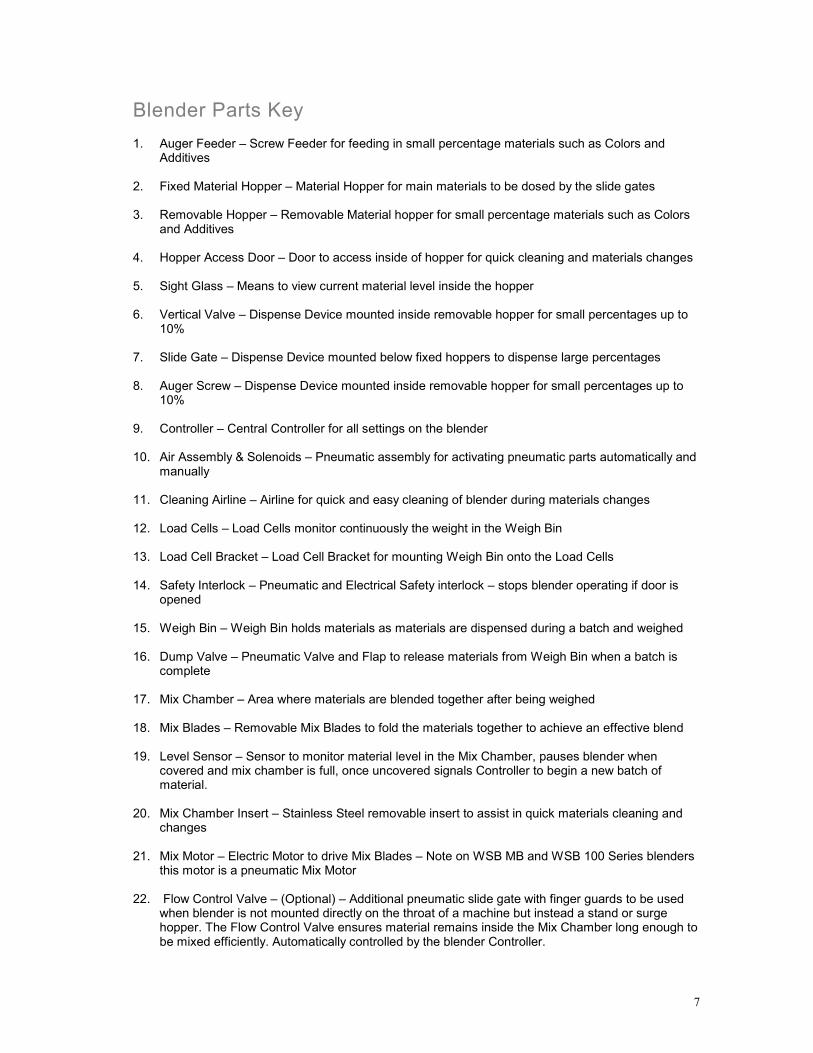
Blender Parts Key
1. Auger Feeder – Screw Feeder for feeding in small percentage materials such as Colors and Additives
2. Fixed Material Hopper – Material Hopper for main materials to be dosed by the slide gates 3. Removable Hopper – Removable Material hopper for small percentage materials such as Colors
and Additives 4. Hopper Access Door – Door to access inside of hopper for quick cleaning and materials changes 5. Sight Glass – Means to view current material level inside the hopper 6. Vertical Valve – Dispense Device mounted inside removable hopper for small percentages up to
10% 7. Slide Gate – Dispense Device mounted below fixed hoppers to dispense large percentages 8. Auger Screw – Dispense Device mounted inside removable hopper for small percentages up to
10% 9. Controller – Central Controller for all settings on the blender 10. Air Assembly & Solenoids – Pneumatic assembly for activating pneumatic parts automatically and
manually 11. Cleaning Airline – Airline for quick and easy cleaning of blender during materials changes 12. Load Cells – Load Cells monitor continuously the weight in the Weigh Bin 13. Load Cell Bracket – Load Cell Bracket for mounting Weigh Bin onto the Load Cells 14. Safety Interlock – Pneumatic and Electrical Safety interlock – stops blender operating if door is
opened 15. Weigh Bin – Weigh Bin holds materials as materials are dispensed during a batch and weighed 16. Dump Valve – Pneumatic Valve and Flap to release materials from Weigh Bin when a batch is
complete 17. Mix Chamber – Area where materials are blended together after being weighed 18. Mix Blades – Removable Mix Blades to fold the materials together to achieve an effective blend 19. Level Sensor – Sensor to monitor material level in the Mix Chamber, pauses blender when
covered and mix chamber is full, once uncovered signals Controller to begin a new batch of material.
20. Mix Chamber Insert – Stainless Steel removable insert to assist in quick materials cleaning and
changes 21. Mix Motor – Electric Motor to drive Mix Blades – Note on WSB MB and WSB 100 Series blenders
this motor is a pneumatic Mix Motor 22. Flow Control Valve – (Optional) – Additional pneumatic slide gate with finger guards to be used
when blender is not mounted directly on the throat of a machine but instead a stand or surge hopper. The Flow Control Valve ensures material remains inside the Mix Chamber long enough to be mixed efficiently. Automatically controlled by the blender Controller.

8

9
Controller Nomenclature
Front Panel
1.1 Keypad 1.2 LED Status Display 1.3 Main Display 1.4 Alarm Beacon 1.5 Materials Thumbwheels 1.6 Fuses 1.7 Power Cord 1.8 On / Off Switch 1.9 Outputs for additional Feeders
(NOTE – Feeder Outputs – These 2 outputs are not available on WSB MB and WSB 100 Series Blenders.)
1.10 Options - High Sensor Mount or Remote Alarm Output 1.11 Air Solenoid Connection 1.12 Optional – Low Sensor Mount
Left Side Panel
2.1 Stop End of Cycle / Continue Switch 2.2 Computer Serial Connection / Optional Fieldbus Connection 2.3 Printer / text file USB Output (Earlier 6811 controllers have a parallel port, not USB) 2.4 Load Cell Port Input 2.5 Optional – Extrusion Control 2 Way Interface 2.6 Immediate Pause / Continue Switch 2.7 Ethernet Communications (MLAN Protocol / G2, port 9999, Modbus, port 502 (12-12 only) Right Side Panel
3.1 Silence Alarm Button 3.2 Electrical Mix Motor Operation Switch – Timed (Default), On or Off 3.3 Electrical Mixer Output Fuse 3.4 Electrical Mix Motor Power Plug
(NOTE – Mixing Controls – These 3 features not available on WSB MB and WSB 100 Series Blenders – fitted instead with Pneumatic Mixers.)
3.5 Mix Chamber Level Sensor 3.6 Input Audible Alarm Loudspeaker

10
Tutorial for controllers using FOUR software. This TUTORIAL BOOKLET is designed to help FIRST TIME USERS understand and operate the CONTROLLER on the MAGUIRE WEIGH SCALE BLENDER. We have written it for those who have never seen this unit before. Follow the instructions, one page at a time, with the controller next to you. Another booklet, our OPERATION AND MAINTENANCE MANUAL, covers everything there is to know about this controller. Everything. Here, in the "TUTORIAL", we only cover the important points, just enough to make it work for you, and to allow you to feel comfortable with the controls. The CONTROLS that you are going to learn about consist of:
1. TOGGLE SWITCHES 2. THUMBWHEEL SWITCHES 3. KEYPAD
In the KEYPAD section we will cover:
1. keys that work in the AUTOMATIC mode, and 2. keys that work in the PROGRAM mode.
In the PROGRAM mode we will cover the keys for:
1. LOAD CELL calibration 2. PARAMETERS 3. STAR functions, and 4. TESTING
After the controls, we will cover ALARMS, and how to respond to them. You only need to know about Toggle switches and Thumbwheel switches to make the system run. However, it is helpful to know the rest and you will always be more comfortable having covered everything.
GETTING STARTED:
NOW PROCEED TO: TOGGLE SWITCHES
NEXT PAGE

11
Toggle Switches On the FRONT of the controller, There is a single toggle switch:
It controls all power to the controller and the weigh scale blender. Because the computer memory chip inside contains a small battery, all the information that the unit has learned while running will NOT be lost when you turn the unit off. You can turn power off in the middle of a run, if you like, and then turn it on again and the blender would just start right up without any problems.
Turning power off in the middle of a batch might cause one batch to be blended incorrectly, but it will not cause any other problems. Never be afraid to just turn the unit off at any time. When you turn it back on, it will work just fine.
Continue / Stop End of Cycle / Immediate Pause Switches On the LEFT SIDE of the controller: There are two switches:
These provide two ways to STOP the blender.
The “IMMEDIATE PAUSE” switch stops the unit IMMEDIATELY.
The “STOP - END OF CYCLE” lets the blender finish a full cycle before stopping.
BOTH must be UP for your blender to run.
Only use the PAUSE switch if you want to make some change or adjustment in the middle of a cycle.
Most of the time you will want the cycle to finish first.
When you use the STOP - END OF CYCLE switch, the blender will complete the batch it is currently blending and then stop at the end of that cycle. SO.....
Leave the PAUSE switch "UP" in the CONTINUE position.
Use "STOP - END OF CYCLE" to start and stop the blender
12
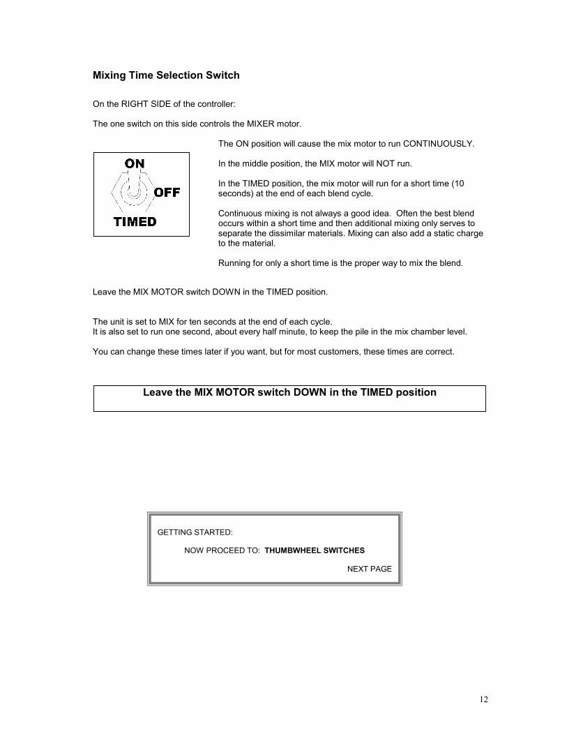
Mixing Time Selection Switch On the RIGHT SIDE of the controller: The one switch on this side controls the MIXER motor.
The ON position will cause the mix motor to run CONTINUOUSLY.
In the middle position, the MIX motor will NOT run.
In the TIMED position, the mix motor will run for a short time (10 seconds) at the end of each blend cycle.
Continuous mixing is not always a good idea. Often the best blend occurs within a short time and then additional mixing only serves to separate the dissimilar materials. Mixing can also add a static charge to the material.
Running for only a short time is the proper way to mix the blend.
Leave the MIX MOTOR switch DOWN in the TIMED position. The unit is set to MIX for ten seconds at the end of each cycle. It is also set to run one second, about every half minute, to keep the pile in the mix chamber level. You can change these times later if you want, but for most customers, these times are correct. .
Leave the MIX MOTOR switch DOWN in the TIMED position
GETTING STARTED:
NOW PROCEED TO: THUMBWHEEL SWITCHES
NEXT PAGE

13
Thumbwheel Switches There are three. All controllers (that use "FOUR" software) are designed to control up to FOUR components. We could have called these components 1, 2, 3, and 4. But instead we decided to call them:
Everyone uses NATURAL. Most customers use REGRIND. Most use COLOR, and some use another ADDITIVE.
Of course "Color" is an additive. We could have called them ADDITIVE 1 and ADDITIVE 2, but we decided that since most customers use a color, we would just name one COLOR and the other ADDITIVE.
While there are FOUR components, you only enter THREE settings. These are for COLOR, ADDITIVE and REGRIND.
There is NO setting for NATURAL. The computer knows that NATURAL will be ALL of the blend, except for the space required for the other three.
So the settings for Regrind, Color, and Additive indirectly tell the computer how much Natural to dispense.
To put it another way, you only have to think about how much Regrind, how much Color, and how much Additive you want. The Computer figures out the Natural for you.
GETTING STARTED:
NOW PROCEED TO: SETTINGS
NEXT PAGE

14
Settings
The FIRST component to be dispensed is REGRIND. If you want TWENTY PERCENT of your blend to be REGRIND, set the "Regrind" THUMBWHEEL switch to 20 percent. This will be: 20.0 If you want fifty percent of the blend to be Regrind, set the Regrind switch to: 50.0 That is all you need to do for Regrind. If you run out of Regrind, the blender is set to just continue and fill the space with the other components. You can change this so the alarm will sound when regrind runs out, but majority of customers prefer to continue on. If you do NOT use any Regrind, just set Regrind to: 00.0 NATURAL is dispensed next. Since there is no setting for Natural, you don't have to think about this. Natural will always be the entire batch, less the room needed for the Regrind, Color, and Additive. The computer will figure this one out for you.
GETTING STARTED:
NOW PROCEED TO: COLOR AND ADDITIVE SETTINGS
NEXT PAGE

15
Next is COLOR. If your color supplier says that you should mix color to natural at a RATIO of 1 to 25, that is 1 part color to 25 parts Natural, this makes color 4 percent of the Natural. You will set FOUR percent 04.0 on the COLOR switches. If your supplier recommends a ratio of 1 part color to 50 parts natural, this is TWO percent, or a setting of: 02.0 This is all you have to do for COLOR. Set the percentage that the Color is of the Natural. The computer does NOT add Color to any Regrind that you may have dispensed. Color is added only to the Natural. If you do not use any Color, just set Color to: 00.0 Last to be added is ADDITIVE. Additive is set just like the Color. It is a percent of the NATURAL only. For example, if you use 1 part additive to 100 parts Natural, set the switch to: 01.0 If you do not use any Additive, just set Additive to: 00.0 That is all there is to the THUMBWHEEL SWITCHES. You can, at this point, just turn the unit on and it will work. Many customers go no further than this. You don't need the keypad to make the unit run, but.... the Keypad offers many additional features. To feel like a WEIGH SCALE BLENDER professional, you should go through the rest of this booklet. It will allow you to feel very comfortable with the entire controller and will put the many additional features within easy reach.
GETTING STARTED:
NOW PROCEED TO: KEYPAD
NEXT PAGE

16
KEYPAD
Your WEIGH SCALE BLENDER has TWO modes of operation:
AUTOMATIC, and PROGRAM.
When you turn it on, it is in the AUTOMATIC mode and is ready to go. If the switches on the left side are UP, your unit will begin to blend immediately.
You don't have to do anything to be in this mode,
just turn it on.
BUT....if you want to make changes to internal settings, print out information, or do other things using the KEYPAD you will have to be in the PROGRAM mode.
ALL KEYS work in the PROGRAM mode. Only a FEW KEYS work in the AUTOMATIC mode.
In any case, the system MUST be between cycles, (at the end of a cycle) for any keypad entries to be made.
So ..... You will always switch to "STOP - END OF CYCLE" before you use the KEYPAD. Look at the KEYPAD. The TOP row of keys are the only ones that work without being in the program mode. The top row is: Most customers never use the middle three keys, RECIPE, BATCH, and FAST; so these are "turned OFF". They will NOT work unless you intentionally turn them on by changing a parameter in the PROGRAM mode. The OPERATION AND MAINTENANCE MANUAL covers this.

17
VIEW Key
The VIEW key simply displays some information for you. You can press it at any time. You don't need this information to operate the machine, but you should know how to retrieve it.
Try it now. Each time you press the VIEW key, a new piece of information is displayed. First the current DATE, then the TIME, then the date and time that all totals were last cleared to zero. Then you will see the number of cycles run, followed by the total material used, in pounds, for Regrind, Natural, Color, and Additive. The grand total follows this and then the message (00=CLEAR) is displayed for 5 seconds. If you want, press 00 within 5 seconds to clear all fields. EXIT Key
This is IMPORTANT. EXIT always works, in all modes.
It is always the key to press to GET OUT of whatever it is you are doing. It's a good key to know.
Now for the rest of the KEYS.
ALL the OTHER KEYS work only in the PROGRAM mode
GETTING STARTED:
NOW PROCEED TO: PROGRAM MODE
NEXT PAGE
18
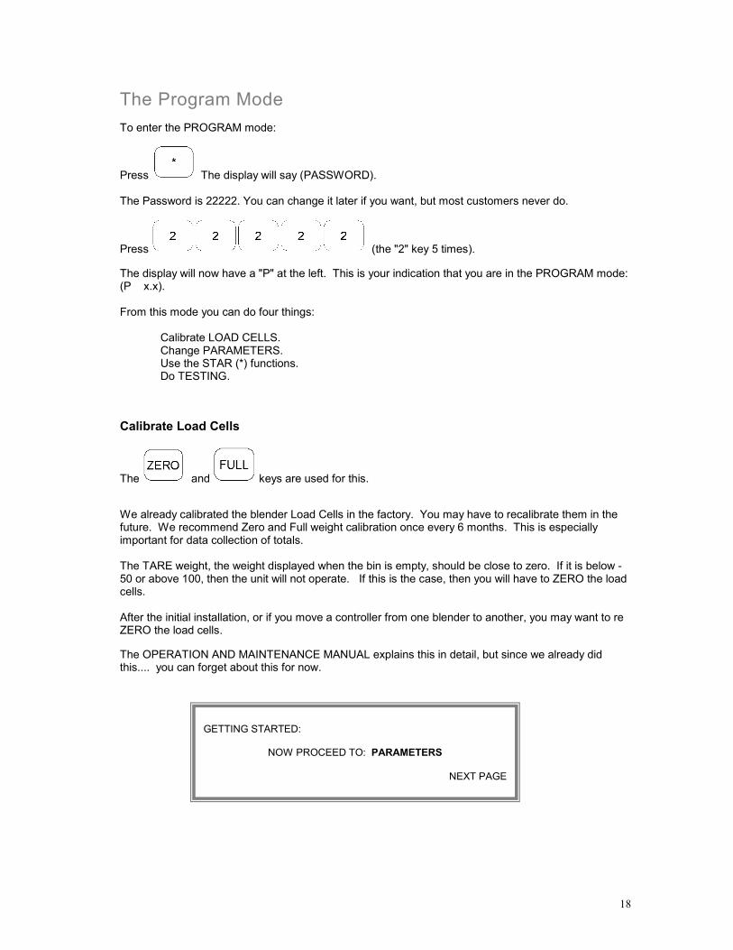
The Program Mode To enter the PROGRAM mode:
Press The display will say (PASSWORD). The Password is 22222. You can change it later if you want, but most customers never do.
Press (the "2" key 5 times). The display will now have a "P" at the left. This is your indication that you are in the PROGRAM mode: (P x.x). From this mode you can do four things:
Calibrate LOAD CELLS. Change PARAMETERS. Use the STAR (*) functions. Do TESTING.
Calibrate Load Cells
The and keys are used for this. We already calibrated the blender Load Cells in the factory. You may have to recalibrate them in the future. We recommend Zero and Full weight calibration once every 6 months. This is especially important for data collection of totals. The TARE weight, the weight displayed when the bin is empty, should be close to zero. If it is below -50 or above 100, then the unit will not operate. If this is the case, then you will have to ZERO the load cells. After the initial installation, or if you move a controller from one blender to another, you may want to re ZERO the load cells. The OPERATION AND MAINTENANCE MANUAL explains this in detail, but since we already did this.... you can forget about this for now.
GETTING STARTED:
NOW PROCEED TO: PARAMETERS
NEXT PAGE

19
Parameters
The key is used to change PARAMETERS. Every time you press it, the next parameter is displayed. The OPERATION AND MAINTENANCE MANUAL explains all of these in detail. If you want to change one, just remember, you must be in the PROGRAM mode and then press the PARA key until you see the one you want to change. (If you accidently pass the one you want in the list, press the * key to back up.) There are over 60 parameters. Each one has a 3 letter identification code followed by a 5 digit number. The number keys are used to enter or change any parameter. A typical parameter looks like this on the display:
MIX MOTOR TIME SECONDS: MIX 00015 MIX00015
40-character display (2007 and later) 8-character display (pre-2007) This particular parameter tells us the MIX motor will run for 15 seconds at the end of a cycle. You may need to adjust some particular parameter for some special problem or circumstance. But for now, you can leave all of them alone.
Don't forget the key to get out of the list. .
IF YOU ARE NOT SURE WHAT YOU ARE DOING WITH PARAMETERS then PLEASE leave them alone
Before you change any, READ THE OPERATION AND MAINTENANCE MANUAL.
GETTING STARTED:
NOW PROCEED TO: STAR FUNCTIONS
NEXT PAGE

20
Star (*) Functions
The key followed by a two digit number (00 to 99) allows access to the STAR functions. All STAR (*) functions are all listed on the LABEL on the under side of the hinged controller door. Lift it up to read the list of * functions. Each function is different. You may be required to enter the change you want or to press the * key again to display various options.
Again, the key will get you out. The most important STAR function is the one you will use to SETUP your system. This is explained later. A few other important STAR functions are:
Correct the DATE, or the TIME if you are running reports and care about having the correct time shown on these reports. Your Weigh Scale Blender doesn't need the correct date, but you might.
Change the weight unit from pounds to kilograms for customers who are on the metric system (everyone except the U.S.) and who want to be able to print reports in kilograms. The blender does all blending in grams and coverts to pounds or kilos for reports only. Turn the Printer flag on (if you have a printer) so you can see exactly what your blender is doing every cycle; in other words, see that it is as accurate as we say it is.
To print a copy of all parameters. A printer must be connected. Up to 13 lists will print, a General list and 12 component lists. Only components that are turned "on" will print.
Save process information for future recovery if the software gets zapped. You will notice, on the left side of the controller, an INSTRUCTION LABEL. It tells about this very useful Star function. Read it. You may need it.
For a complete listing of all Star Functions please refer to the OPERATION & MAINTENANCE Manual.

21
Manual Testing & Operation Look at the second row of keys: These keys work only when followed by a "device" key. "Device" keys are down the right edge of the keypad, as shown here:
For example: Press "OPERATE" followed by "NATURAL" and the Natural slide gate will open.
The OPERATE key is good for testing that all devices work. This is part of the CHECK OUT procedure for each new blender.
The other keys have little use in normal operation. If you just must know what they do, see the OPERATION AND MAINTENANCE MANUAL.
For now, you can forget them. That is all for the PROGRAM mode.
Remember: press the key to get out of the PROGRAM mode.
GETTING STARTED:
NOW PROCEED TO: ALARMS
NEXT PAGE

22
ALARMS: The ALARMS are: the STOBE light flashing, the BEEPER sounding. There are only a few things that can cause an ALARM: 1. If a component runs out of material, or for any other reason is not feeding correctly. 2. If you try to operate the unit with the weigh bin removed. 3. If you try to operate the unit with material stuck in the weigh bin. Running out of Material: Running out of material, will cause the display to flash with the letter R, N, C, or A in the first position. The letter indicates which material is not feeding, "N" for NATURAL and "C" for COLOR. Just add material and the unit will recover by itself. The blender never stops trying to meter it in. Incorrect Weight Reading too Low: This is caused by the TARE weight being too low (below -50). If the bin is not in its place, then the display will shown minus about 1200 grams. The blender will not start with this low tare weight. So just put the weigh bin back in place. Incorrect Weight Reading too High: This is caused by the TARE weight being too high (above 100). Check the bin and see what the problem is. There may be something stuck in the bin.

23
Conclusion This completes our brief outline of ALL the CONTROLS. As you read through the OPERATION AND MAINTENANCE MANUAL, you will now have a better idea how all the software parts fit together and how you can make changes and add features. A few important points to help you feel comfortable:
• The key always gets you OUT • As with any computer, turning power off also gets you out
• Turning power off will never hurt
• Pressing keys on the keypad will never change anything as long as you are NOT in the
program mode
• Parameters DO effect operations. Do not change them unless you understand them
• If you are confused or have question, call us. 610 459 4300. Ask for service Thank you for taking the time to complete this booklet. We hope your Maguire Weigh Scale Blender serves you well.