wrought-iron bridge hangers - transportation research...
TRANSCRIPT

10. W. Black, D.S. Mossr and 14. Emerson. Bridge' Tenperatures Derived frorn Measurements of Move-
nent.. ÎRRL ReporÈ 748. Transport and Road Re-search Laboratoryr Departnent of the Environ-nent, Crovrthorner Berkshirer England, 1976.
11. !t.J.N. Prlestley. Effects of Transverse Ten-perature Grailients on Bridges. Report 394.Ministry of wÕrksr welllngton' New Zealand,Sept.1972.
12. M.J.N. Priestley. Tenperature Gradients inBridges--some Design Consí¿lerations. New zea-land Engineering, voI. 27. Patt 7, July 1972,pp. 228-233.
13. D.R.H. I{aher. The EffecÈs of Differential Tem-perature on continuous concrete Bri¿lges. CivilEngi.neerÍng Transaetíons, Institute of Enqi-neers of Australia' voI. CEI2, Part Ir April].970, pp. 29-32.
14. Vl.I.J. Price. Discussion of Papers EntitledMedway Briilge: Design, by O.A. Kerensky and G.tittle; and Medway aridge: Constructionr bytil.F. Hansen and J.A. Dunster. Proc., Institu-tion of Civil Engineers, vol. 3I, June 1965,pp.162-156.
15. !4.J.N. Priestley. tinear Heat-Flow and ThermalStress Analysis of concrete Bridge Decks. Res.Report 76./3. Department of Engineering, Uni-versity of Canterburyr Christchurch' New Zea-lancl' Feb.1976.
113
I6. ùl.J.N. Priestley. Design Therrnal Gradients forConcrete Bridges. New zealan¿l Engineering,Vol. 31' Part 9' Sept. 1976' pp. 213-219.
L7. M. Emerson. Ternperature Differences inBridges: Basis of Design Reguirements. TRRLReport 765. Transport and Road Research Labo-ratory, Departnent of the Environnent, crow-thorne, Berkshire, Englandr 1977.
18. steel, concrete, and composite Bridges--PartI: General state¡nent. British stan¿lard BS5400. British Stan¿lards Institution, Crow-thorner Berkshire, Englandr 1978.
19. ì{. Radolli and R. Green. Thernal Stresses inConcrete BrÍdge Superstructures Under SurunerConditions. fn Transportation Research Record547. TRBr National Re6earoh CounciI, llashing-ton, D.c., 1975, pP. 23-36.
20. I'l.J.N. Priestley and I.G. Buckle. A¡nbientThermal Response of concrete nridges--BridgeSeminar, 1978. Summary volune 2. structureco.¡mittee' Road Research Unitr NationåL RoadsBoard, Wellington, New Zealandr 1979.
2L'. F. Leonhardt, G. Kolbe' and J. Peter. Ternpera-ture Differences Endanger Prestresse¿l ConcreteBriilges. Brefon-und Stahlbetonaur No. 7, July1965, pp. 157-163.
Publicøtion of thís paper sponsored by Comnittee on Concrete Bridges.
Before the refine¡nent of the steel-making process,wroughÈ iron was widely used as the princÍple struc-tural material in briclge construction. lt was usedin many railroad structures during the perioil fromthe late 1800s to the early 1900s. Although thenaterial properties of wrought iron have been wellknown since the beginníng of its use, the weldedfatigue behavior has hever been adequately quanti-fied. Thus a study on the fatigue behavior ofwelded wrought-iron splice plate repairs on Norfolkand Western Raihray Bridge No. 651- in Hannibal,Iqissouri, is prèsenteil. Welded repairs are knor.¿n toresult in l-ow fatígue strength details with steelcomponents. Because the structural membêrs werewrought iron rsith steel reinforcementr it wasdesired to evaluate the seriousness of the resultingwelded details and to assess the degree of cumula-tive danage that rnay have occurred.
BRIDGE DESCRIPTION
The Norfolk and lilestern Railway Bridge was origi-nally built for the wabash Railroad in 1888 by theDetroit lron and Bridge works. The bridge spans the!4ississippi River nith seven truss spans and onecontinuous swing span for a total length of I'580 ft(Figure 1). It carries a single track and has atruss spacing of 18 ft. The bridge members are con-
Fatigue Behavior of Welded Wrought-Iron Bridge Hangers
PETER B. KEATING, JOHN W. FISHER, BEN T. YEN, ANd WILLIAM J. FRANK
ABSTRÀCT
The behavior of fatigue crack growth andfatigue strength of welded lap splicewrought-iron hangers in a railroad bridgewas studied. The origínal wrought-ironhangers were lap spliced with steel platesfor the purpose of tightening the members.Fíeld inspection revealed cracks in thewelded lap splices. Examination of simu-Iated test joints and cracked hanger splicesin the laboratory indícated that fatiguecracks would develop from weld deposits atthe cut of the wrought-iron bar, propagateinto the steel splice plate, and cause fail-ure. Fatigue cracks could also propagateinto the wrought-iron bars but would be ar-resteil by the slag (íron silicate) string-ers. Breaking of the wrought-iron bar onlyoccurred when the applied stress was quitehigh in conparison with the yield point.l'leasured live-load stresses in the actualbridge member were relatively Iow. Eval-ua-tion of traffic and load records índicatesthat the effective live-load stresses wouldbe well below the fatígue strengths of thesespli.ced joínts. No inminent problen of fa-tigue failure is expected in the hangers.

114
FIGURE I View of bridge.
structed of riveted built-up wrought-iron sectionsand eyebars. Span F, which contains the most severewelded repair detail, is a níne-panel, 176-ft, 4-in.-long sirnply supported span (Figure 2). AII di-agonals, bottoÍr chord members, and the UI-MI and U8-M8 hangers are comprised of eyebar pairs.
Throughout its history, the bridge has underqonean extensive number of repairs ancl revisions (notethat these data are from the records and summariza-tions of repairs to Bridge 651 of the Norfolk andIÍestern Railroad). This includes span shorteningand relocation, stringer replacenent, and eyebartightening. Beginning ín 1937, a period during theearly development of the welcling process, nany ofÈhe repairs incorporated welding, sone Èo an ex-treme. Conmon to old, pin-ended truss bridges, manyof the eyebar members loosened vrith tine and re-guired tightening. The corrective repair procedureused on this bridge was to cut the eyebar body andthen to weld steel lap shear splices over the cut.A small- length eras cut out of the eyebar body andthe two cu! enals hrere drawn together so as to reten-sion the member. Splice plates were welded oneither side, thus overlapping the cut (Figure 3).The steel lap plates rrrere of A7 material.
A continuous fiIIet weld h'as placed around theentire peri¡neter of each lap plate, which resulted
Transportation Research Record 950
FIGURE 4 Toe crack in transverse weld.
in both transverse and longitudinal welds, the lat-ter bridging thè exposed gap between the twowrought-i.ron plate ends. This was done on many ofthe diagonals, bottom chord nembers, and on six ofthe eíght eyebar hangers in span F, as well as eye-bar nembers in the other seven spans. For thehangers in span F, the original cross-sectional areaof the wrought-iron bar is 4.0 in.2. The adilitionof the splice plates increases the total area by 12percent to 4.5 in.2. This type of tightening pro-cedure was a common method of repair before thefãtigue strength of weldnents became known. ThèA¡¡erican Railway Engineèríng Association (ÀREA)specifications nor¡, provide procedures for eyebartightening by heating and upsetting of the eyebarbody.
FIELD INSPECTION
A detailed inspection of the bridge revealed fatiguecracks in the r¿e1ded lap splices. The most severecrackíng was found in the transverse wetds in thehangers of span F, where the cracks had coalescedacross the toè of the transverse weld. Figure 4shows the presence of the crack along the entirelength of the transverse fillet weld. Àlso, fatiguecracks were found in the welded gap at the center ofthe lap splice (Figure 5). Although each hanger iscornprised of a pair'of eyebars, with a conbinedcross-sectional area of 8.0 in.2, the inspectionrevealed that only one eyebar was carrying the 1oad.The other eyebar was found to be slack, even duringlive loading of the span. This may have occurredfrom pin wear, pin rotation, or irnproper tensioningduring repair. This condition effectively doubledthe stress range level in the active member, whichresulted in a more serious situation. À study wasundertaken to determine the severity of the crackingand to ¿letêrmíne what corrective ¡neasures werenecessâry to prevent failure of the mernber.
FIELD ¡4EASUREIIENTS
Concurrent with Èhe field inspection h'âs thè strâingauging and monitoring of one hãnger in span ¡'. Anelectrical resistance strain gauge \dag nounted onthe load-carrying rnèmber of hanger Ul-Ml-. Strainreadings were taken during passage of severalfreight Èrains and of a test train of knovrn r.reightat various speeds. This allowed for the correlãtionof the field-measured sÈresses with the stresses ob-
U8U7U6U5u4U3
L9L8L6L5L4L3L2 L7LI
FIGURE 2 hofile of span F.
t" x 4" wRouGHl tRoN BAR
3/4" X 3" X 24" STEEL
FIGURE 3 Plan of lap splice repau'.

Keating et aI.
FIGURE 5 Gack in welded gaP.
tained fro¡n a cornputer rnoilel of the structure. À16ot
it pernitted the effective stress range for thêrecording period and, subsequentlyr for the entirelife of the briatge to be estirnated.
Figure 6 shows the frequency of naxinum stressfor 10 trains during the recording period, excludingstress ranges less than 7 ksi. The maxi¡nurn recordedstress ranfte was 16 ksí, which accounted for onLy3.5 percent of the total number of cycles. The ef-fective stress range (Sr Miner) was calculated tobe 10.6 ksi. Examination of the stress historiesindicated that there occurred one load cycle per caror locomotive for the hanger ¡ne¡nbers. Each wheelgroup (the tt¡o trucks from adjoining cars) gave onecomplete cyc1e.
PHYSICAL PROPERTIES
wrought iron is a ti.ro-cornponent metal that consistsof high purity iron and iron silicate, a particulartype of glasslike s1ag. Originally, the slag con-tent of wrought iron (2.5 percent by weight) vras
thought to be an undesirable impurity. But it was
SPAN F
115
eventually realized that the slag r'¡as responsiblefor the desirable Properties of wrought iron--itsresistance to corrosion and to fatigue.
Nineteenth century furnace tenperatures were nothigh enough to keep the refineil iron from solidífy-ing and trapping sone of the nolten slag Cluring thefinal stages of the refining operation. Bessemerrsdevelopnent of steel rnaking was originally inten'ledto produce nrought iron of higher qual-ity and lowerco"t thun what was currently available. But theprocess resulted in steel that did not cÕntâin theslag. It had superior mechanlcal properties and
could be ¡nanufacturecl in greater quantities and at a
Iower cost.In wrought iron, slaq is distributed throughout
the iron rnatríx, generaLly in the for¡n of threads offibers that extenil ln th€ direction .of rÛIling. Ap-proxinately 250 '000 of the siliceous fibers arepresent in each cross-sectional square inch' corro-sion resistance is attributable to the purity of theiron baser freedom from segregated impurities, antlthe presence of the slag fibers ¿listributed through-out the netal base. The slag fibers are present insufficient nurnbers to form an effective barríer tothe process of corrosi'on, forcing it to spread overthe surface of the metal rather than to Pit or pene-trate (1).
TensJIe tests of rvrought iron bars taken from thestructure gave a ¡nínimu¡n yield stress of 26 ksi at0.002 offset. The tensile strength was neasured as
45 ksi. These results aqree with AST!¡i specifica-tions for À42-I3 wrought-iron plates.
FATIGUE TESTS
The laboratory fatigue tests of the hanger lapsplice were conducted in two parts to accurately as-sess the severity of the transverse wel¿l cracks'Initiallyr specimens were fabricated an'l tested byusing pieces of wrought-iron bars salvage¿l from span
E. This span was replaced when the original span
was knocked into the river during a barge collision'Laterr as a result of the replacement of the crackedhangers, the actual weldecl joints fron span F became
available. These were also fatigue teste'lr exanined,and then compared with the fabricatecl specinens'Figure 7 shows a lap splice repair of span F in theatternating stress testing rnachine.
Testíng of Fabricaterygg-imens
A total of seven tests were conducted by using threêdifferent constant amplitude stress ranges and twovariations of the ldeld orientation. The fírst threetest specinens were run at a stress range of 12 ksi.Althouqh there was noticeable cracking along the toeof the transverse welcl¡ failure of these threespecirnens did not occur at this location. The flrsttwo specimens incorporatecl the center junction,which was subjected to a stress rânge of 10 ksi'This resulted in failure of the specimen at thisIocation at 2.1 million cycles for specirnen I and3.6 million cycles for specímen 2. The cracks ini-tiated in the longituclinal weld that bridged the gapbetween the wrought-iron plates an¿l propagated intothe steel plates. These failures correspond to thefatígue life for orilinary steel and plot near thecategory D fatigue strength curver as can be seen inFigure 8. However' the test sa¡nple is so small thatassessing the resistance using category E is a rea-sonable lower bound. Clearly, it was this locationthat controlled the fatigue life of the lap splicecon¡iection.
AfÈer failure of the steel plates, both specimensI and 2 were regripped to continue testing of the
l]-r, ",n.,
| | t tsaz rrottic )
iI¡l-t's7 M'ner
( Meosurod )àe
()zl¡Jfot¡lfrro
7 I 9 lO ll 12 13 14 15 16
Sr- STRESS RANGE, ksi
FIGURE 6 Histogram for hanger, span F.

116
tranavêrse welds that provide¿l a cover plate detail.Both speci¡nens erere tèsted to 20 rnil-l-ion cyclêsvrithout failure at thís location, although notice-able cracking at the hrelal toe and in the rdeld oc-curred. specirnen 3, which incorporated only the en¿ldetail, \ras teste¿l to 6 ¡nillion cycles without fail-ure and then was destructively exanined to evaluatethe cracking.
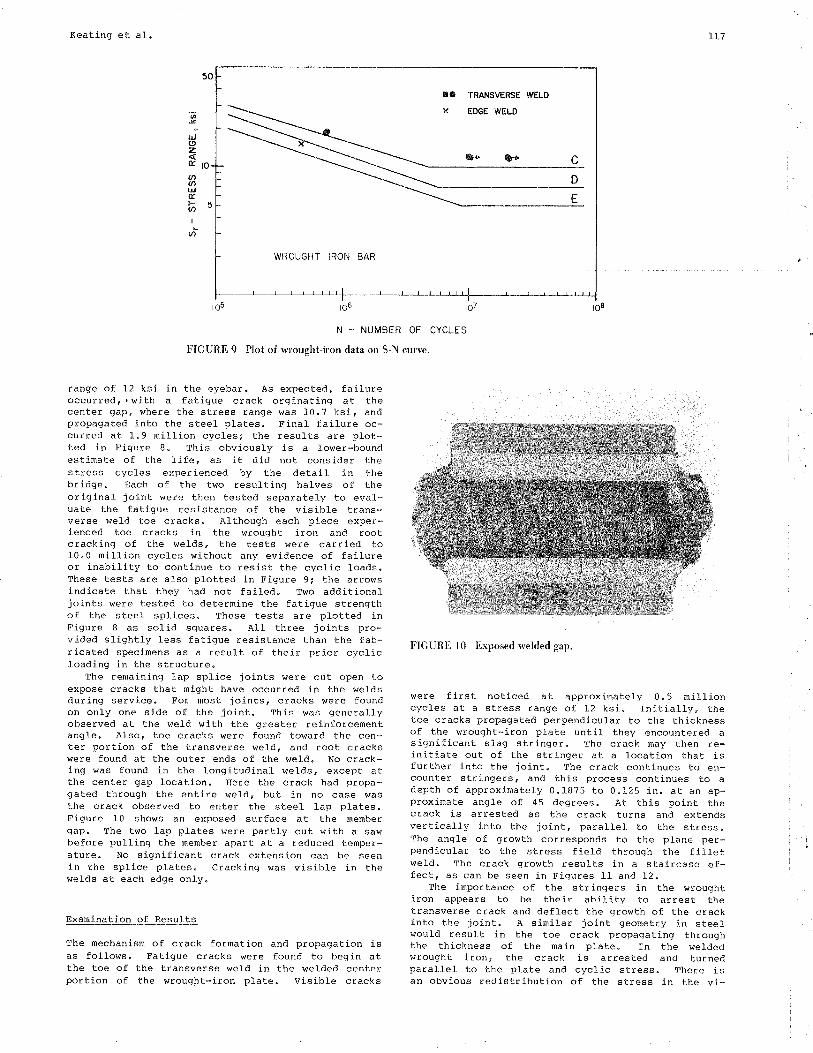
Because failure at the toe r¡eld of the wrought-lron plate did not result in faílure at 12 ksi, thestress range vras increasetl to 18 ksl for the nextthree speci¡nens. At the higher stress level failureoccurre¿l at the toe of the transverse weld beginningat approximately 0.74 million cycles. This wasstill well above the fatigue strength expected at acategory E cletail. AII fatigue test results appli-cable to the wrought-iron ne¡nbers are plotted inFigure 9. Those tests that rdere stoppêd beforefaiLure are indlicated $rith an arrow.
Transportation Research Recoral 950
Becauge the properties of wrought iron are notisotropic but are ilirèctionally dependent, a seventhtest specimen was fabricated with the steel platesvrelded to the edges of the wrought-iron bar. Thespecimen eras tested at a constant stress range of 15ksi, and the fatigue crack propagate¿l perpendicularto the edges of the elongateil stringers. thís clidnot result in crack arrest, and the failure occurredat 0.46 nillion cycles. This failure lífe plotswithin the scâtter band of a category E cletail andis shor¡n by the cross in Figure 9.
In order to evaluate the fracture toughness ofthe toe crack, the temperature was lov¡ered on twospecirnens during testing. Speci¡nens 1 an¿l 4, run atstress ranges of I2 and 18 ksi, respectively, didnot fail by fracture with a reduction in temperatureto -400F. Thé Èêst resutts iäTlc¡itê thãF the *eléledwrought iron had a relatively high resistance tocrack instability at reduced temperatures. It wasconcludecl that the toe-crackeil eyebars vrould notfail because of brittle fracture.
Testing of Span F Hangers
Six of the eight hangers in span F that containedthe lap splice repaír were removed from the struc-ture. The six lap splice joints were cut fron theme¡nbers and shipped to the laboratory for detaileclexa¡nínation. Several were fatigue tested, anal the
remainder grere cut open to reveal the extent of thecracking.
The actual- bridge lap splices were foun¿l to be oflower quality i{ith respect to the welding and work-nanship rdhên conpared to the taboratory-fabricatedspecimens. These repairs were conductetl in 1937,when the welding process had not been adequatelydevelopeil, and they were nade uncler field condi-tions. The majority of the transverse welds werefound to be undersized for the gíven plate thíck-ness. The weld sizes rangeal fron 0.1875 to 0.25 in.for a 0.875-in. plate. Current clesign specificationsrequire a ninimum weld size of 0.3125 in. In aildi-tion, the welds exhibited porosity and unclercuttingof the $¡rought-iron p1aÈe. Many of the weld pro-files had a contact angte that greatly exceedeil 45degrees.
One full-size¿l joint was placed in the alternat-ing stress machine anil fatigue tested at a stress
FIGURE 7 Alternating stress test machine,
.- FABRICATEO SPECIMENS
STEEL LAP PLATE
N - NUMBER OF CYCLES
FïGURE B Plot of steel lap plate data on S-N curve.
50
ro
:t¡J(9zÉ.
U'aDt¡lÉ.Þv,I
an
¡66ro?t06t05
Keating et a1. 117
to
5
at
L¡.¡(9zÉ,
U'Ø¡¡JÊl-(t
I
(t
¡O TRANSVERSE WELD
WROUGHT IRON BAR
N _ NUMBER OF CYCLES
FIGURE 9 Plot of wrought-iron data on S.N curve.
t08to7t06t05
range of 12 ksí ín the eyebar. As expected, failureoccurred' . with a fatigue crack orginating at thecenter gap, where the stress range was 10.7 ksi, andpropagated into the steel plates. Final failure oc-curred at I.9 ¡nillion cycles; the results âre ptot-ted in Figure 8. Thís obviously is a lower-boundestimate of the Iife, as it diil not consíder thestress cycles experienced by the detail in thebridge. Each of the two resulting halves of theoriginal joint were then tested separately to eval-uâte the fatigue resistancè of the visible trans-verse weld toe cracks. Although each piece exper-ienced tôe cracks in the wrought íron and rootcracking of the \,¡elds, the tests lrere carried to10.0 million cycles without any evidence of failureor inability to continue to resist the cyclic toads.Thesê tests are also plotted in Figure 9; the arrovrsindicate that they had not failecl. Two adilitionaljoints r.rere tested to deterrníne Èhe fatigue strengthof the steel splices. These tests are plotted inFigure I âs solid sguares. ALl three joints pro-vided slightly less fatigue resístance than the fab-ri-cated specimens as a result of their príor cyclicIoading in the structure.
The remaining lap splice joints were cut open toexpose cracks that ¡night have occurred in the weldsduring service. For nost joints, cracks were foundon only one side of the joint. Thls \ras generallyobserved at the weld !,rith the greater reinforcementangle. AIso, toe cracks were found toward the cen-ter portion of the transverse vreld, and root crackswere found at the outer ends of the weld. No crack-ing was found in the longitudinal welds, excepÈ atthe center gap location. Here thè crack had propa-gated through the entire weld, but in no case wasthe crack observed to enter the steel lap plates.Figure 10 sholrs an exposed surface at the nenbergap. The two lap plâtes r.¡erè partly cut with a sawbefore pulling the rnember apart at â reduced tenper-ature. No significant crack extension can be seenin the splice plates. Cracking was visible in thev¡elds at each edge only.
ination of Results
The mechanisn of crack formatíon and propagation isas follows. Fatigue cracks erere found to begin atthe toe of the transverse weld in lhe wel-iled centerportion of the wrought-iron plate. VisÍb1e cracks
FIGURE l0 Exposed rvelded gap.
were first noticed -at approximately 0.5 rnillioncycles at a stress range of 12 ksi. Initially, thetoe cracks propagatecl perpendicular to the thicknessof the wrought-iron plate untí1 they encountered asignificant slag stringer. the crack may then re-initiate out of the strÍnger at a location that isfurther into the joint. The crack continues to en-counter stringerè, and this process continues tÕ adepth of approximately 0.1875 to 0.125 in. at an ap-proximate angle of 45 degrees. At this point thecrack is arrested as the crack turns and extendsvertically into the joint, parallel to the stress.The angle of groerth corrèsponds to the plane per-pendicular to the stress field through the filletweld. The crack growth results in a staircase ef-fect, as can be seen in Figures 11 and 12.
The importance of the stringers in the wroughtiron appears to be their ability to arrest thetransverse crack and deflect the grovrth of the crackinto the joint. A sinilar joint geometry in steelwould result in the toe crack propagating throughthe thickness of the ¡¡ain plate. In the weldedvrrought ironr the crack is arrested and turnedparallel to the plate and cyclic stress. There isan obvious redistribution of the stress in thê vi-

118
FIGURE 1l Crack growth in test specimen.
:'1. , i . .'
FIGURE 12 Crack growth in span F hanger.
cinity of the crack front. As the crack moves intothe joint following the laninated stringers' thestress is redistributed to the longitudinal welds.The redistribution of the stress to the outer por-tions of the joint results in root cracking in boththe longitudínal welds and in the outer portions ofthe transverse vrelds because the weld sizes weresnall. Eventually all thê load \Ías transferredthrough the longitudinal welds, which resulted incontinued crack extension along the weld throät.
Fatígue testing at a high stress range of 18 ksiresulted in a naximu¡n stress level of 21 ksi. Thisinaximu¡n stress corresponds to approxinately 80 per-cent of the measured yield stress of the wroughtiron. As the fatigue crack propagated into thejoint, the cross section of the wrought-iron platewas reduced. This resulted in yieldinq of the netsection of the wrought-iron plate and also resulteclin conÈinuèd crack extensíon, with the eventualfailure of the section. Such high stress rangeswould not be expected in a wrought-iron structure.
The test resulÈs fron the welded wrought-ironspecimens and the actual hangers are sumnarÍzed inFigures I and 9. These têsts demonstrate that thefatigue resistance is much greater thân that pro-vided by category E--the expected fatigue categoryfor such welded steel details. None of the details
Transportation Research Record 950
tested at a stress range of 12 ksi faileil as a re-sult of the crack that formed at the weld ternina-tions. These cracks were arrested and did not in-pair the load-earrying capability of the joint.Failure, should it. occur, was shown to devel-op atthe gap regÍon.
TRAFFIC STUDY AND FATIGUE ASSESSIqENT
To accurately assess the severity of fåtigue crack-ing in welded lap splices, the stress history spec-trum for the hanger me¡nber must be determined. Byreviewing the traffic that the structure has exper-ienced and its relation to the stress levels in thehangerr an esti¡nate can be made of the cumulativefatigue damage and the renaining l-ife of the struc-ture.
Because of the long history of the bridge and achange in ownership, limited traffic data were ob-tainable fro¡n the Norfolk and western Railway.Available data included the following: train time-tables from 1936 to 1963, annual gross tonnage fig-ures from I97l to l-981, and a listing of all trainmovements during 1982. Because these data were in-sufficient for an adequate traffíc study, it becatnenecessary to supplenent it v¿íth other sources ofdata. Correlation $ras made with traffic ilata fronCanadian National (cN) Rail at britlges that were onlines si¡nilar to that of the line that Brídge 651traverses (2,3). CN has done extensive trafficstudies on many of their linesr which allows them todevelop useful averages and to indicate particulartrends from an extensive data base.
civen the limited amount of traffic data, thetraffic frequency and distribution nust be esti-rnated. There are several importânt parameters thatcan be used to generate the necessary infornation.These are the number trains per day, Ioconotiver¿eights, engine units per train, annual gross ton-nage, ancl carload distributíon. Although not allparameters are known for each year under studyr notall- are needed for any one particular year. Themethod used in a particular tine period was dictatedby the available infornation.
The period of concern for the hangers is fron1937, when the welded repairs vrere performed, to thepresent. Àlso, an estimation for the future (to theyear 2000) was made. For each year, the nunber oflocomotives and cars that crossed the bridge wasestimated. Studies by CN concluded that only cars¡nore than 60 gross tons have a sígnificant effect onthe fatigue life, and all other lighter trafficcould be ignored (4). Fron 1937 to 1954 it was as-sumed that only the locomotives contributed tofatigue damage because carloads seldom exceeded 60tons. Assuming one locotnotive per train (typicalwith steam locomotives), the yearly total r¡as cal-culated from the timetables. Because extra freighttrains were run in a given time slot, the nunber ofscheduled trains, both passenger and freight, wasincreased by 10 percent. Beginning in 1955r wíththe conplete conversion to iliesel, carloads began toincrease. The number of cycles per year fron thecarloads $ras deterníned by multiplying the annualgross tonnage by the percentage of cars greater than60 tons and dívidíng by the root-mean-square valuefor carloads greater than 60 tons. The number oflocomotive loadings was deternined from availab!etínetables, with the realization that more than onediesel unit could be used on one train. Beginningin 1962, when train tables rdere no Longer available,the nunber of locor¡otive units was deterninecl bydividing the annuaJ. gross tonnage by the estímatedaverage gross tons pulled by one unit. Carloadcycles were deteinined as previously mentioned.
II
(
t'
I
I rl:tII
,irrl
'i
' r:
1

Keating et aI.
Eaving the number of loadíng cycles cåused byboth loconotives and carloads for each year, it wasnecessary to determine the stress ranges caused bythem. A three-dimensional linear finite-elernentnodel of the span was developed and calibrated withthe strain-gaugê data obtained during the field in-vestigation. This exarnination de¡nonstrated that in-pact effects were negligible and that a space-frarneanalysis ldas applicable to the structure. The ín-fluence of dynamic effects is re¿luced on the struc-ture because of the presence of a sharply curvedtunnel inmediately adjacent to the bridge site. Thisimposes spee¿l restrictions on all train traffic.Figure 13 shows the correlation betrdêen the theo-reticâI and measured stress history for a gíventrain pâssage. From the computer analysis an in-fluence diagram was developed for the hanger mem-ber. A typical wheel-spacinq configuratíon was as-surned for both a stean and diesel loconotive and atypical car. Each was given a unit weight andpassed across the influence diagra¡n; then the stressrange was determined. Then, by using the estimatedstatic .values for locomotive and car \reights, theeffective stress range could be deter¡nined for eachyear. By using Minerrs linear fatigue damage rela-tionship, the extent of the fatigue danage could beestinated by sumning the nunber of cycles at a par-ticular stress range for a given yeår.
À problem of deternining the correct effectivestress range that corresponded to all danage cycles
r19
arose because of the slackness in some in the eye-bars. The actual accumulated fatigue darnage esti-¡nate for a given loadecl member is boundecl by thecondition of both bars carrying the Load an¿l by thecondition that only one carries the entire load forthe ¡ne¡nber. Assuming that both eyebars erere Loade¿lresulted in an effective stress range (Sr Miner)equal to 4.3 ksi for 3.I nillion variabl-e loadcycles. Projected to the yêar 2000, the figure in-creâses to 4.5 ksi for 5.2 million cycles. Withonly one bar participating, the 1982 value increasesto 9.8 ksi for 3.1 nillion cyoles, and the futuredamage increases to 10.3 ksi for 5.2 million cycles.These points are plotted in figure 14 and are com-pared to AÀSHTO fatigue categories and the fatiguetest data developeil on the welded vrrought-ironj oints.
The predicted effective stress range and accunu-lated cycles of the variable loãding plot weLt belowthe fatigue resistance provided by weJ-ded wrought-iron end details. The tesÈs on laboratory-weldedspecinens and on cracked detaíls renoved from span Fdenonstrate¿l that a stress range of 12 ksi would notproduce failure, even after 20 million cycles ofloading. The effectivê stress range anil cunulativecycles in 1982, as well as those projected to 2000,are well belovr those resistance values. Had bothhangers been effective and the stress range de-creased, an even greater nargin of reserve lifewould exist.
TIME )
FIGURE l3 Comparison of measured and theoretical response.
. - WROUGHT IRON BAR
O - STEEL LAP PLATE
N - NUMBER OF CYCLES
FIGURE 14 Plot of estimated fatþe life for hangers, span F.
50
5
6t
l¡.1ozÉ,(r,(¡,l¡JÉ.t-oI
U'
ó6rô7to6rö3

L20
Because the lap plâte splices are more criticalat the cross section at the center of the joíntwhere the eyebar was cut, those vêlues are plottedin Figure 14. The increased cross-sectional areadecreases the effective stress range to 3.8 ksi ln1982 if both bars are effective and to 8.7 ksi ifonly a single bar 1s carrying the load. The sma}l-degree of cracking observed in the field and in theeyebars removed fron the structure suggests thatboth hangers were carrying the load throughout muchof their life. Ha¿l both hangera shared the load, noapprecíabLe danage would have developed for thetraffic projected to the year 2000.
SI'M¡¡IARY AND CONCLUSTONS
As a result of the fatigue tests of weliled wroughtiron with welded lap splice repairs and the correla-tion vrith the loa¿l hístory of the bridge, the fol-lowing conclusions were reached.
1. Surface cracks were found to deveÌop at thetoe of the splice plates that \rere welded to thesurface of the \rrought-iron eyebars at cycJ-e livesconparable to welcled steel components. These crackswere foundl Èo have no adverse effect on the fatigueresistance of the wrought-iron members because theygrere arrestêd by the vrrought-íron slag stringers.
2. An evaluatÍon of the load history to whichthe nembers were subjected inalicated that the wel-dtoe cracking would be expected. It primarily re-sulted because the two eyebar hangers rdere not shar-ing the load. One eyebar was found to be loose, andthis increased the cyclíc stress in the other eyebarby slightly less Èhan 50 percent.
3. Laboratory fatigue tests were carried out onsimulated welded joints and on several of thecracked eyebar hanger splices. The simulated testjoints denonstrated that the r.rrought iron woulil ar-rest the fatigue cracks that forned at the weld toeat stress levels expected in the structure. Theweld toe cracks encounteretl the flattened longitudi-na1 stringers and were arrested as the crack de-flectecl parallel to the cyclic stress. The crack-arrested details were able to sustain 20 nillionstress cycles at 12 ksi yrithout any further evidenceof distress. The cracked hangers were also fatíguetested, and they yielded cornparable results.
4. The laboratory tests also denonstrated thatthe steel splice plates were the more critical de-tail. The four tests carried out provided a fatigueresístance comparable to category D, although theyare classified as category E details. Because thestress range at the critical steel sectíon was Ìessthan the wrought-iron barr the hangers had not ex-perienced much growth at those sections.
Transportatíon Research Recorcl 950
5. The stress history analysis and laboratoryevaluation clenonstrated that the other rveld-repairedmenbers (such as chord and díagonals) were not sus-ceptíble to any appreciable crack growth and wouldnot be fatigue critical.
6. A pilot test on the edge-welded wrought-ironspJ-ice demonstrated that the stringers were not ef-fective ín arresting fatigue crack growth.
ACKNO!|ILEDGIIIENT
This study was sponsored by the Norfolk and ¡{esternRailway. The authors are indebted to E. Bond, as-sistant chief engineer of structures, for his co-operation and assistance with this study. . Theauthors are also inalebted to the staff of FritzEngineering Laboratory, Lehigh University, for theirassistance throughout this study. H.T. Sutherlan¿lassisted with both the field stu¿lies and the fatiguetests, R. Sopko with photography, and R. Dales andC. Hittinger with the laboratory testing.
REFERENCES
l-. ,f. Aston and E.B. Story. Wrought lron, Its Manu-facture Characteristics and Application. A.M.Byers Company, 1939.
2. I.A.S. Elkholy. Estinated Fatigue Danage in the83r-0 Deck Truss Span of the Muskoka RiverBridge, ltíle 116."8, Newmarket Subdivision, Hunts-ville, Ontario, Canada. Technical Report. Cana-dian National Rail, Montreal, Quebec, .Canada,April 1981.
3. R.A.P. Sldeeney and I.A.S. Elkholy. EstinatedFatigue Damage in the 2O6t-3 Through Truss Spanof the Ottawa River Bridge, Ste Anne de Bellevue,Quebec, Canada. Technical Report. Canadian Na-tional Rail, MontreaÌ, Quebec, Canada, ilune 1980.
4. R.A.P. S\deeney. The Load Spectrum for the FraserRiver Bridge at New Westninster, B.C. Proc.,American Railway Engineering Association, Wash-ington, D.C., 1976.
Publícdtion ol this paper sponsored by Committee on þnamics and FieldTestirtg of Bridges.