wr-ey21w - jacks small engines
TRANSCRIPT
WISCONSIN ROBIN WR-W1 -EY21 WPM REV DATE: 01-92
Introduction
This catalog is designed'to identify Wisconsin Robin parts.
When ordering parts, it is always advisable to list the engine model, specification number and serial number. With this information, we can check your order for any incorrect part numbers. Use your Service Parts List to ensure proper part number and nomenclature identification.
TELEDYNE TOTAL POWER reserves the right to modify, alter and improve engines and parts. Part numbers and the structure of parts may change from those shown in this catalog.
Table of Contents
Air Shrouding ....................................................................................................................... 1
Crankcase and Cylinder ................................................................................................... 2-3
Crankshaft, Camshaft, Piston, Rod, Valve and Drive End : ........................................ 4-5
Throttle, Governor and Control Box .............................................................................. 6-7
Fuel Tank ............................................................................................................................... 8
Fuel Pump ............................................................................................................................. 9
Ignition Timer, Coil and Alternator ................................................................................. 10
Starting Motor and Switch ........................................................................................... 11-12
Air Cleaner and Intake Manifold ...................................................................................... 13
Carburetor and Automatic Choke Carburetor pages ................................................... 14
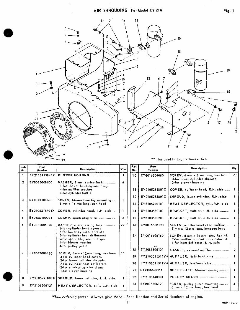
AIR SHROUDING For Model EY 21W Fig. 1
i 7 2 14 18
Number
2 EY0032008000
3 EY0043108160
4 EY 21053 1580 1 X
5 EYOM6100021
6 EY0032006000
7 EY0017006120
8 EY 21 05295801 X
9 EY2105300121
Description
3LOWER HOUSING ............................ MASHER, 8 mm, spr ing lock ............ 1-for blower housing mounting &for muffler bracket 1-for cyl inder baf f le
;CREW, blower housing mounting .... 8 mm x 16 mm long, pan head
:OVER, cylinder head, L.H. side ..
:LAMP, spark plug w i re ..................
VASHER, 6 mm, spr ing lock ............ &for cylinder head covers 5-for lower cylinder shrouds 3-for cyl inder heat deflectors 2-for spark plug wire c lamps &for blower housing 4-for pulley guard
SCREW, 6 m m x 12mm long, hex head 4-for cylinder head covers 2-for lower cylinder shrouds 2-for cylinder heat deflectors 2-for spork plug wi re clamp 1-for blower housing
SHROUD, lower cylinder, L.H. side
i E A T D E F L E C T O R , cyl., L.H. side
- Ref. No.
1 0 -
11
12
13
1 4
15
16
17
18
19
20
21
22
23
-
19
15
2 1
16
2
** Included in Engine Gasket Set.
Part Number Description
EY0016506080 SCREW, 6 mm x 8 rnm long, hex hd. 3-for lower cylinder shrouds %for blower housing
EY2105285801X COVER, cylinder head, R.H. side ..... EY2105265801X SHROUD, lower cylinder, R.H. side
EY.2105270101 H€AT DEFLECTOR, cyl., R.H. s ide
EY2103530101 BRACKET, muffler, L.H. side .......... EY2103530201 BRACKET, muffler, R.H. side ........ .. EY0016508120 SCREW, muffler bracket to muffler ..
8 mm x 12 rnm long, hexagon head
EY0016508160 SCREW, 8 mm x 16 mm long, hex hd. 2-for muffler bracket to cylinder hd. 1-for heat deflector, L.H. side
** EY2083500101 GASKET, exhaust muffler ................_. EY2103011511YA MUFFLER, r ight hand side ................ EY2103021511YA MUFFLER, left hand side .................. EY2105530111 DUST PLATE, blower housing ..........
EY2105440301 PULLEY GUARD ................................ EY0016506120 SCREW, pul ley guard mounting ......... ~
6 mm x 12 mrn long, hex head
When ordering parts: Always give Model, Specification and Serial Numbers of engine.
3
2
1
1
1
1
4
-
1 MRP-109-2
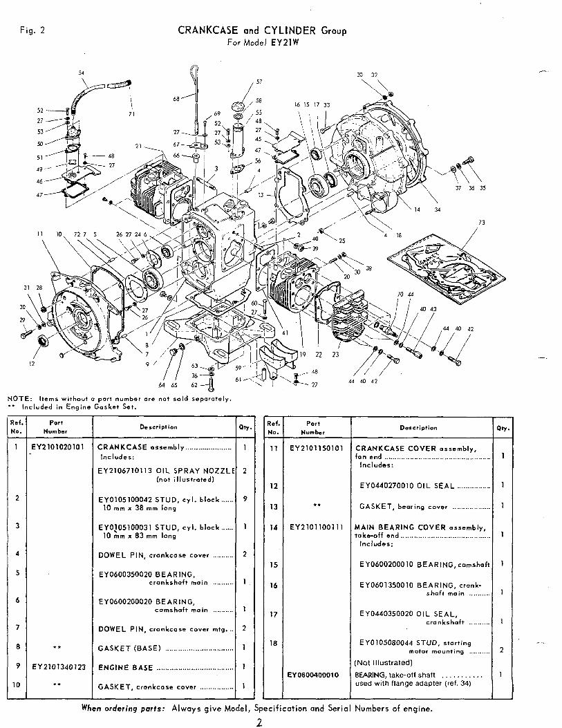
Fig. 2 CRANKCASE and CYLINDER Group For Model EY2lW
NOTE: Items without a part number are not sold separately. '* Included in Engine Gasket Set.
Description
CRANKCASE assembly ...................... Includes:
EY2106710113 OIL SPRAY NOZZLI (not i l lus t ra ted)
EY0105100042 STUD, cy l . b lock ...... 10 mm x 38 mm long
EY0!05100031 STUD, cy l . b lock ...... 10 rnrn x 83 mrn long
DOWEL PIN, crankcase cover ..........
EY0600350020 BEARING, crankshaft main ..........
EY0600200020 BEARING, camshaf t main ..........
DOWEL PIN, crankcase cover mtg. ..
GASKET (BASE) ................................
ENGINE BASE ....................................
GASKET, crankcase cover ................
- Q t v
1
-
2
9
1
2
1
1
2
1
1
1 -
- Pef. No.
11
-
12
13
14
15
16
17
18
-
Part Number
EY2101150101
**
EY2101100111
EY 060040001 0
Description
CRANKCASE COVER assembly, fan end ................................................
Includes:
EY0440270010 OIL SEAL ..............
GASKET, bearing cover ................
MAIN BEARING COVER assembly,. t a k e o f f e n d ........................................ Includes:
EY0600200010 BEARING,camshaf
EY0601350010 BEARING, crank- shaft main .........
EY0440350020 OIL SEAL, crankshaft .........
EY0105080044 S T U D , start ing motor mounting .........
(Not Illustrated)
BEARING, take-off shaft ........... used with flange adapter (ref. 34)
r-
- -.,
When ordering ports: Always give Model, Specification and Serial Numbers of engine.
2
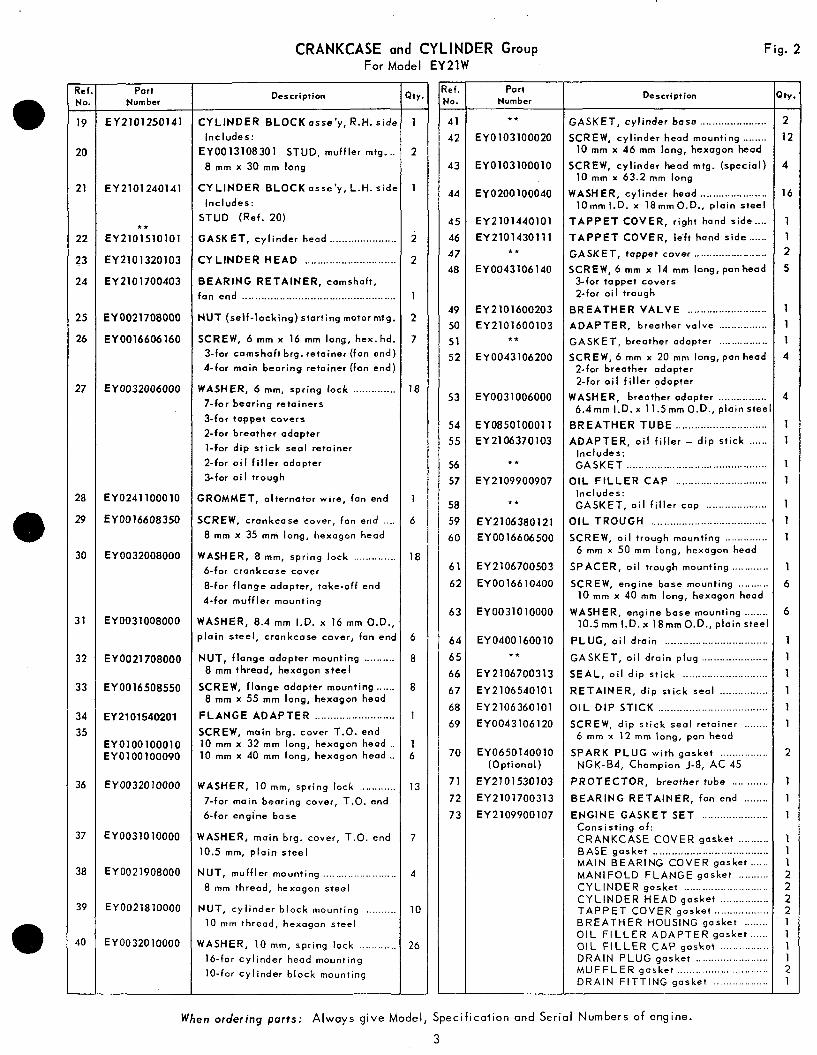
CRANKCASE and CYLINDER Group For Model EY21W
Fig . 2
. Ref . No . 19 .
20
21
22
?3
24
25
26
27
28
29
30
31
32
33
34 35
36
37
38
39
40
.
Part Number
EY2101250141
EY2101240141
EY2101510101
EY2101320103
EY2101700403
t *
EY0021708000
EY0016606160
EY0032006000
EY0241100010
EY0016608350
EY 0032008000
EY0031008000
EY0021708000
EY0016508550
EY2101540201
EYOlOOlOOOlO EY0100100090
EY0032010000
EY0031010000
EY0021908000
EY0021810000
EY0032010000
Description
CYLINDER BLOCK a s s e ’ y . R.H. side
Includes:
EY0013108301 STUD. muffler mtg ... E mm x 30 mm long
CY L lNDER BLOCK asse’y. L.H. side
Includes:
STUD (Ref . 20) GASKET. cyl inder head ......................
C Y L I N D E R H E A D ..............................
BEARING RETAINER, camshaft,
fan end ..................................................
NUT (sel f - locking) start ing motor mtg . SCREW, 6 mm x 16 m m long, hex . hd .
3-for camshoft brg . retainer (fan end)
4-far main bearing retainer (fan end)
WASHER, 6 mm, spring lock .............. 7-for bear ing retainers
3-far tappet covers
2-far breather adapter
1-for dip st ick seal retainer
2- for a i l f i l le r adapter
3-for o i l t rough
GROMMET, alternator wire, fan end
SCREW. cranlccase cover, fan end .... 8 mm X 35 m m long, hexagon head
WASHER, 8 m m , spr ing lock .............. 6-for crankcase cover
E-for f lange adapter, take-off end
&for muff 1 er mounting
WASHER, 8.4 m m I.D. x 16 m m O.D., plain steel, crankcase cover, fan end
NUT, f lange adapter mounting .......... 8 mm thread, hexagon steel
SCREW, flange adapter mounting ...... 8 mm x 55 m m long, hexagon head
FLANGE ADAPTER .......................... SCREW, main brg . cover T.O. end 10 mm x 32 mm long, hexagon head .. 10 mm x 40 mm long, hexagon head ..
WASHER, 10 m m , spring lack ............ 7-for main bearing cover, T.O. end
6-for engine base
WASHER, main brg . cover. T.O. end
10.5 mm, p la in s tee l
NUT. muff ler mounting ........................ 8 mm thread, hexagon steel
NUT. cyl inder b lock mount ing .......... 10 mm thread, hexagon steel
WASHER, 10 mm. spring lock ............ 16-for cyl inder head mounting
10-for cyl inder b lock mount ing
.
>tu . 1 .
2
1
2
2
1
2
7
18
1
6
18
6
8
a
1
1 6
13
7
4
10
26
.
. e f . IO . 41 42
-
43
44
45 46 47 48
49 50 51 52
53
54 55
56 57
58 59
60
61
62
63
64 65
66 67 68 69
70
71
72
73
.
Part Number
t*
EY0103100020
EY0103100010
EY0200100040
EY2101440101 EY2101430111
t t
EY0043106140
EY2101600203 EY2101600103
**
EY0043106200
EY0031006000
EY0850100011 EY2106370103
* *
EY2109900907
**
EY2106380121 EY0016606500
EY2106700503
EY0016610400
EY0031010000
EY0400160010 * *
EY2106700313 EY2106540101
EY2106360101 EY0043106120
EY0650140010 (Opt ional)
EY2101530103 EY2101700313
EY2109900107
Description
GASKET. cy l inder base ...................... SCREW, cyl inder head mount ing ........
10 m m x 46 mm long, hexagon head
SCREW, cyl inder head mtg . (special) 10 mm x 63.2 m m long
WASHER, cyl inder head ...................... lOmm I.D. x 18mmO.D .. p la in s tee l
T A P P E T COVER, r ight hand side .... T A P P E T COVER. k f t hand side ...... GASKET, tappet cover ........................ SCREW, 6 mm x 14 mm long, panhead
3-for tappet covers 2-for o i l t rough
B R E A T H E R V A L V E .......................... ADAPTER. breather valve ................ GASKET, breather adapter ................ SCREW, 6 m m x 20 mm long, pan head
2-for breather adapter 2 - fo r o i l f i l l e r adapter
WASHER, breather adapter ................ 6.4mm I.D. x 11.5mm O.D., p la in stee
BREATHER TUBE .............................. ADAPTER, o i l f i l l e r - dip s t i ck ......
Includes: GASKET ..............................................
O I L F I L L E R C A P .............................. Includes: GASKET, o i l f i l l e r cap ....................
OIL TROUGH ...................................... SCREW, ai l t rough mount ing ..............
6 mm x 50 m m long, hexagon head
SPACER, ai l t rough mount ing ........... SCREW, engine base mounting .........
10 m m x 40 mm long, hexagon head
WASHER, engine base mounting ....... 10.5mm I.D. x l E m m O . D . , plain stee
PLUG, o i l d ra in ................................. GASKET, o i l dra in p lug ..................... SEAL, o i l d i p s t i c k ............................ RETAINER, d ip s t ick seal ............... OIL DIP STICK .................................... SCREW, dip st ick seal retainer .......
6 mm x 12 mm long, pan head
SPARK PLUG wi th gasket ............... NGK.84, Champion J.8, AC 45
PROTECTOR, breather tube ........... BEARING RETAINER, fan end ....... ENGINE GASKET SET .....................
Consis t ing o f : CRANKCASE COVER gasket .........
MAIN BEARING COVER gasket BASE gasket
MANIFOLD FLANGE gasket ......... CYLINDER gasket ........................... CYLINDER HEAD gasket ............... T A P P E T COVER gasket ................. BREATHER HOUSING gasket ....... O I L F I L L E R A D A P T E R gasket ..... OIL F I L L E R C A P gasket ............... DRAIN PLUG gasket ....................... M U F F L E R gasket ............................. DRAIN F ITTING gasket .................
..................................... .....
. ‘ t Y
2 12
4
16
1 1 2 5
.
1 1 1 4
4
1 1
1 1
1 1 1
1
6
6
3 1 1
1 1 1
2
1 1 1
1 1 1 2 2 2 2 1 1 1 1 2 1 .
When ordering p a r t s : Always give Model. Specification and Serial Numbers of engine . 3
Ref. NO.
1 -
2
3
4
5
6
7
-
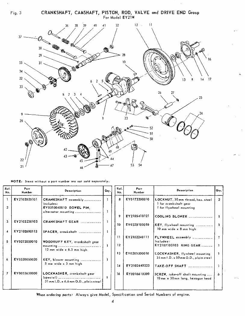
Fig. 3 CRANKSHAFT, CAMSHAFT, PISTON, ROD, VALVE and DRIVE END Group For Model EY21W
36 38 39 40 41 32 12 11
21 J 46 / &-. 47
NOTE: Items without a part number are not sold separately.
Port Number
EY2102020101
EY 2102230103
EY2102600113
EY0323050010
EY0320050020
EY0033630000
~~ -
Description
CRANKSHAFT assembly .................. Includes: EY0310040010 DOWEL PIN, alternotor mounting ............................
CRANKSHAFT GEAR ......................
SPACER, cronkshaft ........................
WOODRUFF KEY, crankshaft gear mounting ..............................................
12 m m wide x 6.5 m m h igh
KEY, blower mounting ...................... 5 mm wide x 5 m m h igh
LOCKWASHER, crankshaft gear (spec ia I ) .............................................. 31 m m l .D.x4.6mmO.D., plain steel
- Ref. Ne.
8 -
9
10
11
12
13
14
16
I 1 53 54
P o r t Number
EY0173300010
EY2105410121
EY0320100010
EY2102240111
EY0205300010
EY 2 102440223
EY0016610300
Description
LOCKNUT, 30mm thread, hex. steel
1 for crankshaft gear 1 for f lywheel mounting
COOLING BLOWER ..........................
KEY, f lywheel mount ing .................. 10 m m wide x 8 mm h igh
FLYWHEEL assembly ...................... Includes:
EY2107100103 RING GEAR ............
LOCKWASHER, f lywheel mount ing
31 m m I.D. x 5 0 m m O.D., p la in s tee l
TAKE-OFF SHAFT ..........................
SCREW, take-off shoft mounting ...... l O m m x 3 0 m m long, hexagon head
1
6
When ordering.parts: Always give Model, Specification and Serial Numbers of engine.
4

CRANKSHAFT, CAMSHAFT, PISTON, ROD, VALVE and DRIVE END Group Fig. 3 For Model EY2lW
- ?ef. NO. - 17
20
21
22
23
24
25
26
27
28
29
30
31
32
33
34
35
-
Part Number
EY0032010000
EY2105420403
EY0205200010
EY0173200010
EY2102250110
EY2102250210
EY2102350107
EY 21 02351 207 EY2102351307
EY2102340113 EY 210234021 3 EY 230234031 3
EY2102330103
EY0565200030
EY2103160111
EY0230220011
EY0053204200
EY 21 03320121
EY0230200050
EY2104170111
EY 21 03540103
EY2104500111
~~~~~~ ~ ~
Description
WASHER, take-off shaft mount ing .... 10 mm spr ing lock
STARTING PULLEY, rope ........._._..
LOCKWASHER, starter pul ley mtg.
NUT, 20 mm thread, hexagon steel .. 1 for s tar t ing pu l ley
1 for camshaft mounting
CONNECTING ROD assembly .......... Includes:
EY2102310123 OIL SCRAPER ........ EY0205080031 LOCKWASHER ._...... EY2102300113 ROD B O L T ..............
CONNECTING ROD assembly
.010" undersize
RING SET, standard s ize ......_........... Consis t ing o f :
COMPRESSIUN RING ........................ SCRAPER RING ........_.... ~ .................. OIL RING .............................................. .010" oversize Ring Set
.020" oversize Ring Set
PISTON, standard size ...................... .010" overs ize P is ton
.020" overs ize P is ton
PISTON PIN ...................................... ..
SNAP RING, p is ton p in ....................
CAMSHAFT wi th p in ion gear ............
SPACER, camshaft gear ....................
WOODRUFF KEY, camshaft gear mtg.
4 mm wide x 5 mm h igh
CAMSHAFT GEAR ............................
SPACER, camshaft ............................
GOVERNOR P L A T E and f lyweight
assembly ........_...
LOCKWASHER, camshaft gear ........ 20.5mm 1.D.x 32mmO.D., p la in s tee l
THRUST P L A T E , governor ............._
- tr. - 6
1
1
2
2
2 4 4
1
2 2 2
2
2
4
1
1
1
1
1
1
1
1
-
- Lef 4 0 .
36 -
37
38
39
40
41
42
43
44
45
46
47
48
49
50
51
52
53
54
Part Number
EY2103340103 ~~ ~~
EY2103350133
EY2083360113
EY 2103370103
EY2083380103
EY2103330123
EY2106410101
EY0200120010
EY2106400151
EY0031008000
EY0032008000
EY2106701503
EY2106390100
EY0031005000
EY 0032005000
EY0043105200
EY 2l06430101
EY0051030250
Description
I N T A K E V A L V E ..................................
EXHAUST VALVE .............................
V A L V E SPRING ..................................
RETAINER, va lve spr ing ...._.............
LOCK, va lve spr ing ............................
V A L V E T A P P E T ................................
GEAR, o i l pump drive ........................
WASHER, oi l pump gear ........._......._..._ 12.5 mm 1.D.x 21 mm O.D., p la in s tee l
ADAPTER ASSEMBLY, o i l pump ......
WASHER, o i l pump adapter ................ 8.4 mm I.D. x 16 mmO.D., p la in s tee l
WASHER, o i l pump adapter mounting
8 mm, spr ing lock
SET SCREW, o i l pump adapter mtg. .. 8 m m x 24 mm long, hexagon head
OIL PUMP assembly .......................... Includes:
EY2106390107 GASKET ......................
WASHER, o i l pump mounting .............. 5.5rnm 1.D.x lOmmO.D.,plainsteel
WASHER, o i l pump mounting ....._........ 5 mm, spr ing lock
SCREW, oi l pump mount ing ....... ~ ........ 5 mrn x 20 mm long, pan heod
STRAINER, oi l pump ..........................
COTTER PIN, o i l pump strainer mtg
3 mm x 25 mm long
- Itv
2 -
2
4
4
4
4
1
1
1
1
1
1
1
1
4
4
4
1
1
- When ordering ports: Always give Model, Specification and Serial Numbers of engine.
5
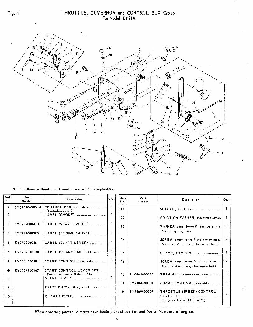
Fig. 4 THROTTLE, GOVERNOR and CONTROL BOX Group For Model EY2lW
- Ref No.
1
2
-
3
4
5
6
7
0
a
9
NOTE: Items without a part number are not sold separately.
Part Number
EY 2104065801 x
EY0732000410
EY0732000390
EY0732000361
EY0732000530
EY2104530101
EY2109900407
Description
CONTROL BOX assembly ................
LABEL (CHOKE) .............................. (Includes ref. 2)
LABEL (START SWITCH) ................
LABEL (ENGINE SWITCH) ..............
L A B E L ( S T A R T L E V E R ) ................
LABEL (CHARGE SWITCH) ............
START CONTROL assembly ............
START CONTROL LEVER SET ......
START LEVER .................................. (Includes Items 8 thru 16)-
FRICTION WASHER, start lever ......
CLAMP LEVER, s tar t w i re ..............
-
- I t r .
1
1
-
1
1
1
1
1
1
1
1
1
-
- 7ef. MO.
11
-
12
13
14
15
16
17
18
e
Port Number
EY0664000010
EY2104400101
EY 2 109900507
Description Q t r
SPACER, stort lever .......................... 1
FRICTION WASHER, s to r tw i rescrew 1
WASHER, start lever 8 start wire mtg. 3 5 mm, spr ing lock
SCREW, star t lever 8 start wire mtg. 2 5 mm x 12 mm long, hexagon head
CLAMP, s ta r t w i re ............................ 1
SCREW, start lever & clamp lever . . . 2 5 mm x 8 mm long, hexagon heod
TERMINAL, accessory lamp ............ 1
CHOKE CONTROL assembly .......... 1
THROTTLE (SPEED) CONTROL L E V E R S E T ........................................ (Includes I tems 19 thru 32)
1
When ordering parts: Always give Model, Specification and Serial Numbers of engine.
6
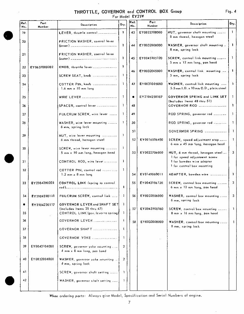
THROTTLE, GOVERNOR and CONTROL BOX Group Fig. 4 For Model EY21YI -
tef. No. - 19
20
21
22
23
24
25
26
27
28
29
30
31
32
33
34
0
35
36
37
38
39
40
41
42
-
Part Number
EY0637000202
EY2104290201
EY2104310111
EY2104230117
EY0043104080
EY0032004000
Description
LEVER, throt t le control ....................
FRICTION WASHER, control lever
(inner) ..................................................
FRICTION WASHER, control lever
(outer) ..................................................
KNOB, throt t le lever _________.................
SCREW SEAT, knob ..........................
COTTER PIN, knob .......................... 1.6 mm x 10 mm long
WIRE LEVER ......................................
SPACER, control lever ......................
FULCRUM SCREW, wire lever ........
WASHER, wire lever mounting .......... 6 mm, spring lock
NUT, wire lever mounting ................ 6 mm thread, hexogon steel
SCREW, wire lever mounting ............ 5 mm x 10 mm long, hexagon head
CONTROL ROD, wire lever ..............
COTTER PIN, control rod ................ 1.2 mm x 8 mm long
CONTROL L INK (spring to control
rod ) .... ....__ ___. _.__________ _ _ _ _ _ _ ______...... .. .... .... ..
FULCRUM SCREW, control l ink ......
GOVERNOR LEVER and SHAFT S E l (Includes Items 35 thru 47) CONTROL L INK (gov. leverto spring
GOVERNOR LEVER __._____.I. . . . . . . . . . . . . . . .
GOVERNOR SHAFT ________..................
GOVERNOR YOKE ............................
SCREW, governor yoke mounting .._... 4 mm x 8 mm long, pan head
WASHER, governor yoke mounting _. k mm, spring lock
SCREW, governor shaft setting ..._....
WASHER, governor shaft setting ......
- aty. -
1
1
1
1
1
I
1
1
1
1
1
1
1
1
1
1
1
1
1
1
1
2
2
1
1
lef . 40.
43 -
44
45
46
47
0
48
49
50
51
52
53
54
55
56
57
5E
Part Number
EY0022708000
EY0032008000
EY0043105120
EY0032005000
EY0031005000
EY2104250107
EY0016506450
EY0022706000
€YO14906001 1
EY0043106120
EY0032006000
EY0043108160
EY0032008000
Description
IUT, governor shaft mounting .......... 8 mm thread, hexagon steel
IASHER, governor shaft mounting .. 8 mm, spr ing lock
CREW, contro l l ink mount ing .......... 5 mm x 12 mm long,.pan head
IASHER, control l ink mount ing .... 5 mm, spring lock
YASHER, control l ink mounting ...... 5.5mm 1.D.x 10mmO.D., p la ins tee l
;OVERNOR SPRING and L INK SET Includes I tems 48 thru 51) ;OVERNOR ROD ..............................
?OD SPRING, governor rod ..............
?OD SPRING, governor rod ........_.....
SOVERNOR SPRING ........................
SCREW, speed adiustment stop ........ 6 mm x 45 mm long, hexagon head
r(UT, 6 mm thread, hexagon steel .... 1 for speed adjustment screw
1 for bowden wire adapter
1 for control 'box mounting
brDAPTER, bowden wire ._......._........
;CREW, control box mounting .......... 6 mm x 12 mm long, pan head
WASHER, control box mounting ........ 6 mm, spr ing lock
SCREW, control box mounting .......... 8 rnm x 16 mm long, pan head
WASHER, control box mounting ........ 8 rnm, spring lock
Itr
1 -
1
1
1
1
1
1
1
1
1
1
3
1
3
3
1
1
When ordering parts: A l w a y s g ive Model, S p e c i f i c a t i o n and Serial N u m b e r s of eng ine .
7
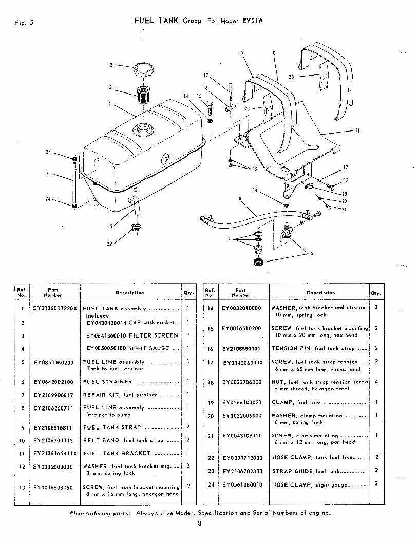
Fig. 5 FUEL TANK Group For Model EY2lW
11
- b f . No. -
1
2
3
4
5
6
7
8
9
10
11
12
13
Number Part
EY2106011220X
EY0851060230
EY0642002100
EY2109900617
EY 210626071 1
EY 210651 581 1
EY2106701113
EY2106165811X
EY0032008000
EY0016508160
~~~ ~
Description
F U E L T A N K assembly .................... Includes:
EY0430430014 CAP with gasket ..
EY0641360010 FILTER SCREEN
EY0850050180 SIGHT GAUGE ....
F U E L L I N E assembly .................... Tank to fuel strainer
FUEL STRAINER ............................
REPAIR KIT, fuel strainer ............
F U E L LINE assembly .................... Stroiner to pump
FUEL TANK STRAP .______...............
F E L T BAND, fuel tank strap ........
FUEL TANK BRACKET ................
WASHER, fuel tank bracket mtg. .... 8 mm, spring lock
SCREW, fuel tank bracket mounting 8 mm x 16 mm long, hexagon head
"
No. Ref.
"
1
1
14
1 15
1
17 1
16
1 18
1
1 19
20
2
2
1
2
21
22
23
2 24
-1
Number Part
EY 00320 10000
EY0016510200
EY2106550101
EY0140060010
EY0022706000
EY0566100021
EY 0032006000
EY0043106120
EY0091712000
EY2106702303
EY0561080010
Description
WASHER, tank bracket and strainer
10 mm, spring lock
SCREW, fuel tank brocket mountins
10 rnm x 20 mm long, hex heod
TENSION PIN, fuel tonk strap ......
SCREW, fuel tonk strap tension .... 6 rnm x 65 mm long, round head
NUT, fuel tank strap tension screw 6 m m thread, hexagon steel
CLAMP, fue l l ine __.. ~ .......................
WASHER, clamp mounting .............. 6 mm, spr ing lock
SCREW, clamp mounting ................. 6 mm x 12 mm long, pan head
HOSE CLAMP, tank fue l l i ne ........
STRAP GUIDE,fueI tank ................
HOSE CLAMP, s igh t gouge.. ....... ...
atr. - 3
2
2
2
4
1
1
1
2
2
2
When o r d e r i n g p o r t s : Always give M o d e l , S p e c i f i c a t i o n and S e r i a l Numbers of engine.
8
- te4, No.
0
1
2
3
4
5
6
7
8
9
10
11
12
13
14
15
16
17
18
19
20
21
22
23
-
-
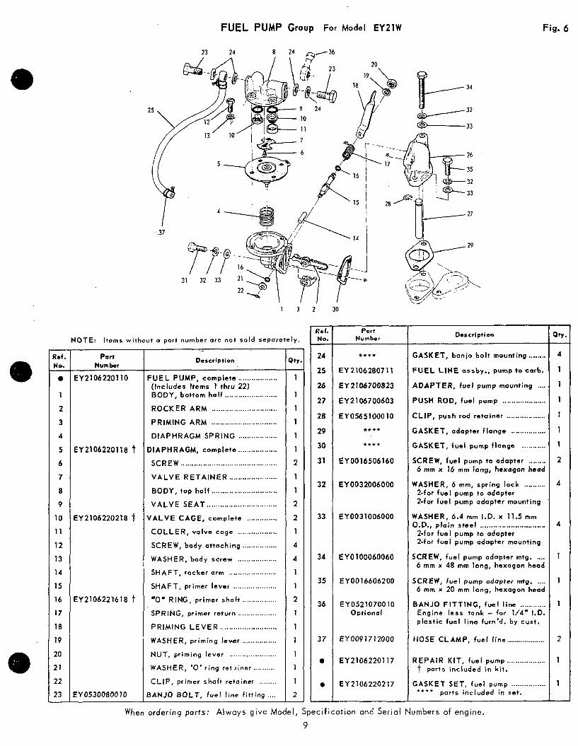
FUEL PUMP Group F o r Model EYZlW
23 24
31 32 33 21
1 3
NOTE: I tems without a part number are not sold separately.
Port Number
EY2106220110
EY2106220118 t
EY2106220218 t
EY2106221618 t
EY0530080010
- Description
F U E L PUMP, complete .................. (Includes Items 1 thru 22) BODY, bo t tom ha l f ........................ ROCKER ARM .............................. PRIMING ARM .............................. DIAPHRAGM SPRING ..................
DIAPHRAGM, complete .................. SCREW ............................................ V A L V E R E T A I N E R ...................... BODY, tap ha l f .............................. V A L V E S E A T ................................
VALVE CAGE, complete .............. COLLER, va lve cage .................. SCREW, body a t taching ................ WASHER, body screw .................. SHAFT, rocker arm ...................... SHAFT, primer lever .................... -0' RING, primer shaft ................ SPRING, primer return .................. PRIMING L E V E R .......................... WASHfR, priming levbr ................ NUT, priming lever ...................... WASHER, '0' r i ng re t l i ne r .......... CLIP, primer shaft retainer ........
3ANJO BOLT, fuel line f i t t i ng ....
- ) t Y
1
1
1
1
1
1
2
1
1
2
2
1
4
4
1
1
2
1
1
1
1
1
1
2
-
-
2 30
- Ref. No.
24
25
26
27
28
29
30
31
32
33
34
35
36
3 7
0
0
-
Number Par i
*t+t
EY 210628071 1
EY 2106700823
E Y 2 106700603
EY0565100010
tttt
tttt
EY0016506160
EYOO32006000
EY0031006000
EY0100060060
EY0016606200
EY0521070010 Opt ional
EY 009 17 12000
EY2106220117
EY2106220217
Description
GASKET, ban io bo l t mount ing ...... .. FUEL LINE assby., pump to carb.
ADAPTER, fuel pump mounting .... PUSH ROD, fuel pump .................... CLIP, push rod re ta iner .................. GASKET, adapter f lange ................ GASKET, fue l pump f lange ........... SCREW, fuel pump to adapter ........
6 mm x 16 mm long, hexagon head
WASHER, 6 mm, spr ing lock .......... 2-for fuel pump to adapter 2-for fuel pump adapter mounting
WASHER, 6.4 mm I.D. x 11.5 mm O.D., plain s tee l ..............................
2-for fuel pump to adapter 2-for fuel pump adapter mounting
SCREW, fuel pump adapter mtg. .... 6 mm x 48 mm long, hexagon head
SCREW, fue l pump adopter mtg. .... 6 mrn x 20 mm long, hexagon head
BANJO F ITT ING, f ue l l i ne ............ Engine less tank - for 1/4' 1.0. p last ic fue l l ine furn 'd . by cust .
HOSE CLAMP, fue l l i ne ...................
REPAIR KIT, fuel pump .................. t ports included in kit.
GASKET SET, fuel pump ................ parts included in set. * ***
Fig. 6
- aw - a 1
1
1
1
1
1
2
4
4
1
1
1
2
1
1
- When order ing por ts : Always g ive Mode l , Spec i f i ca t i on and Serial Numbers of engine.
9
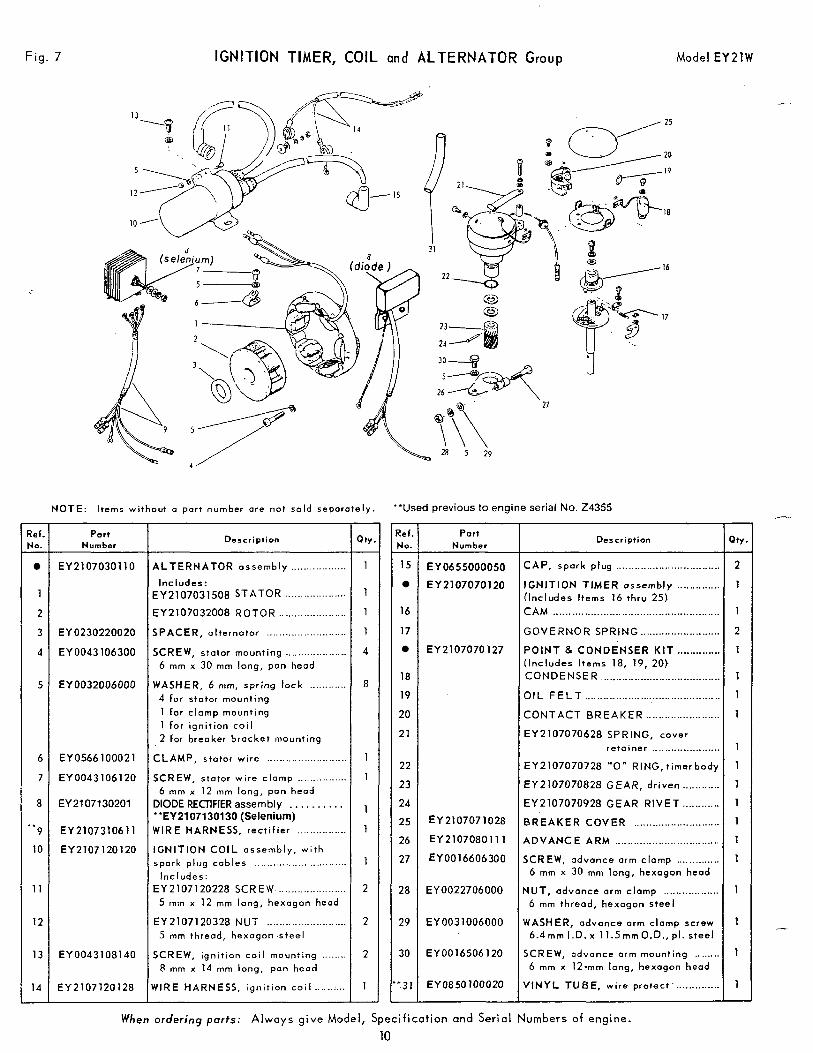
Fig. 7
7
Ref. No. -
1
2
3
4
5
6
7
8
" 9
10
11
12
13
14 -
IGNITION TIMER, COIL and ALTERNATOR Group Model EYZIW
NOTE: Items without a part number are not sold separately.
Port Number
EY2107030110
EY 0230220020
EY0043106300
EY0032006000
EYO566100021
EY0043106120
EY 21 07130201
EY 210731061 1
EY2107120120
EY0043108140
EY2107120128
Description
ALTERNATOR assembly ..................
~ ~ 2 1 0 7 0 3 1 5 0 8 STATOR .._................. Includes:
EYZ107032008 R O T O R ...._.__..............
SPACER, alternator ____....__.___._..........
SCREW, stotor mounting ...._............... 6 mm x 30 m m long, pan head
WASHER, 6 mrn, spr ing lock ............ 4 for stator mounting
1 for clamp mounting 1 fo r ign i t ion co i l 2 far breaker bracket mounting
CLAMP, stator wire _____....._._.._..........
SCREW, stator wire clamp ................ 6 mm x 12 mm long, pan head
DIODE RECllFlER assembly . . . . . . . . . . "EY2107130130 (Selenium) WIRE HARNESS, rec t i f ie r ................
IGNITION C O I L assembly, wi th spark plug cables ..............................
Includes: EY2107120228 SCREW ...................... 5 m m x 1 2 mm long, hexagon head
EY2107120328 NUT .......................... 5 mm threod, hexagon steel
SCREW, igni t ion coi l mount ing ........ 8 mm x 14 mm long, pan head
HIRE HARNESS, i g n i t i o n c o i l ...... :...
8
1
2
2
2
1 -
\ a 5 29 . .
"Used previous to engine serial No. 24355 - tef. 4(0.
15 -
16
17
18
19
20
21
22
23
24
25
26
27
28
29
30
'3 1 -
Part Number
EY0655000050
EY2107070120
EY2107070127
EY2107071028
EY2107080111
EY0016606300
EY0022706000
EY0031006000
€YO016506120
EYO85OlOOOZO
Description
CAP, spark plug ................................... IGNITION TIMER ossembly ............. (Includes I tems 16 thru 25) CAM .... .. .... ......_.._.. ............................... . GOVERNOR SPRING ......................... POINT 8 CONDENSER K I T .............
CONDENSER ..................................... O I L F E L T ........................................... CONTACT B R E A K E R ____._._......._.___... EY2107070628 SPRING, cover
( Includes I tems 18, 19, 20)
retainer ..................... EY2107070728 "0" RING,t imerbady
EY2107070828 GEAR, dr iven ....._..._. EY2107070928 GEAR RIVET
BREAKER COVER ........................... ADVANCE ARM __._____..._.._..... ...._. . ....... SCREW, advance arm clamp .............
6 mm x 30 mrn long, hexogon heod
NUT, odvonce arm clamp .._............... 6 mm thread, hexagon steel
WASHER, advance arm clamp screw 6 . 4 m m l . D . x 1 1 . 5 m m O . D . , p l . s t e e l
SCREW, advance arm mounting ....... 6 mm x 12.mm long, hexagon head
VINYL TUBE, wire protect . .............
- Qr,
2
1
1
2
1
1
1
1
-
1
1
1
1
1
1
1
1
1
1
1 -
When ordering parts: A l w a y s g i v e M o d e l , Specification and Ser ia l Numbers of engine. 10
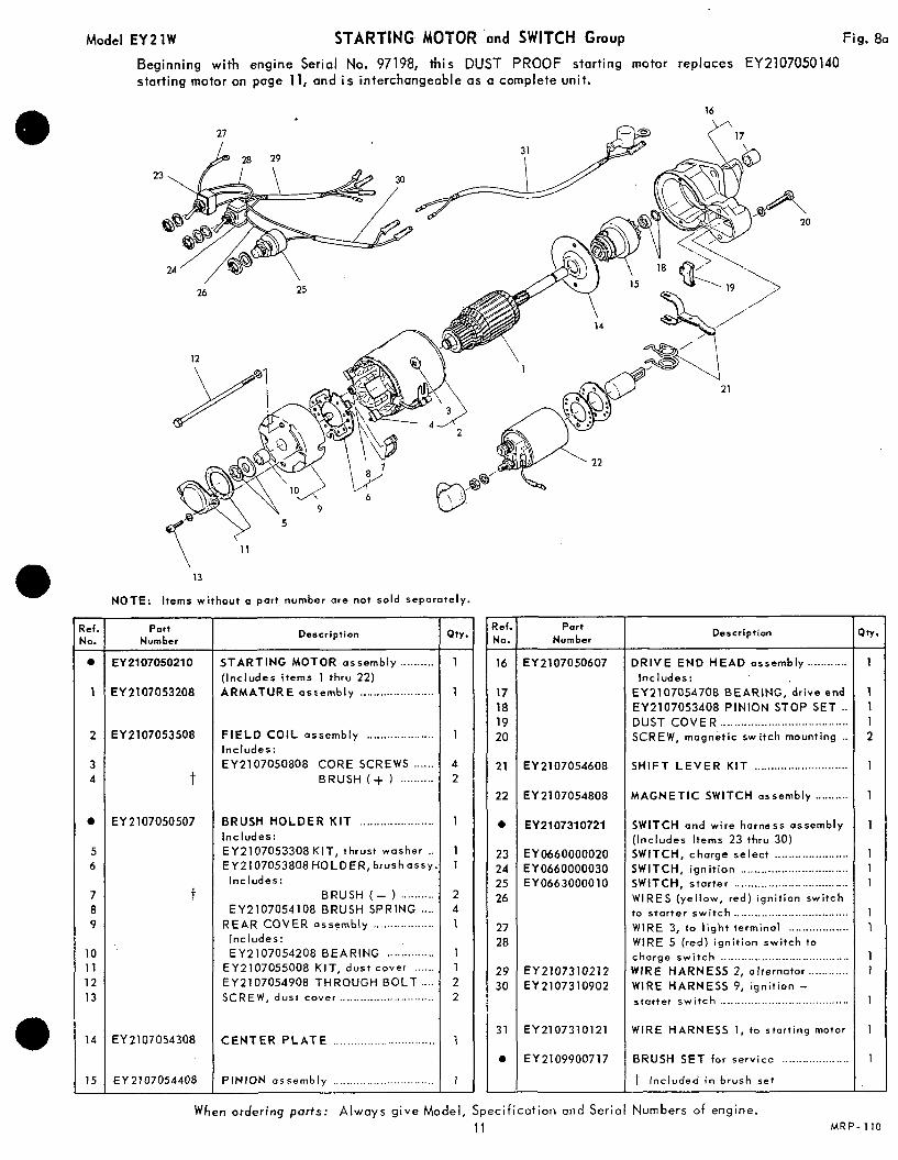
Model EY 2 1 W STARTING MOTOR 'and SWITCH Group Fig. 80
Beginning with engine Serial No. 97198, th is DUST PROOF starting motor replaces EY2107050140 starting motor on page 11, and i s interchangeable as a complete unit.
- ?ef. No.
e -
1
2
3 4
0
5 6
7 8 9
10 11 12 13
14
15 -
27 /
13
NOTE: I tems wi thout a part number are not sold seporately.
Part Number
EY 210705021 0
EY2107053208
EY2107053508
1
EY2107050507
t
EY 2107054308
EY 21 07054408
Description
STARTING MOTOR assembly .......... ( Includes i tems 1 thru 22) ARMATURE oscembly ..._._._..............
F I E L D C O I L assembly .................... Includes:
EY2107050808 CORE SCREWS ...... BRUSH ( + ) ..........
BRUSH HOLDER KIT ...................... Includes: EY2107053308 KIT, thrust wosher .. EY2107053808HOLOER, brushassy
Includes: BRUSH ( - ) ........__
EY2107054108 BRUSH SPRING ....
Includes: EY2107054208 BEARING ...... , .......
EY2107055008 KIT, dust cover ...... EY2107054908 THROUGH BOLT .... SCREW, dust cover ............................
REAR COVER assembly ..................
C E N T E R P L A T E ______._________..............
PINION assembly .._....__.______.........
Qty.
1 -
1
1
4 2
1
1 1
2 4 1
1 1 2 2
1
1 -
- ?sf. No.
16 -
17 18 19 20
21
22
e
23 24 25 26
27 28
29 30
31
0
-
Part Number
EY2107050607
EY2107054608
EY 21 07054808
EY2107310721
EY0660000020 EY0660000030 EY0663000010
EY2107310212 EY2107310902
EY2107310121
EY2109900717
Description
D R I V E E N D H E A D assembly ............
EY2107054708 BEARING, dr ive end
EY2107053408 PINION STOP SET .. DUST COVER .___._.._.,........ ~ .._............... SCREW, magnet ic switch mount ing ..
S H I F T L E V E R K I T ............................
Includes:
MAGNETIC SWITCH assembly ..........
SWITCH and wire harness assembly (Includes I tems 23 thru 30) SWITCH, charge select ...................... SWITCH, i gn i t i on ................................ SWITCH, starter .................................. WIRES (yel low, red) igni t ion switch to s ta r te r sw i t ch .................................. WIRE 3, to l igh t te rmina l .................. WIRE 5 ( red) ign i t ion swi tch to
WIRE HARNESS 2, alternator ............ charge swi tch ......................................
WIRE HARNESS 9, ign i t ion - starter switch ......................................
WIRE HARNESS 1, to starting motor
BRUSH SET for service ___.____..._........
t Inc luded in brush set
When ordering parts: Always give Model, Specification a n d Serial Numbers of engine.
- 3v.
1 -
1 1 1 2
1
1
1
1 1 1
1 1
1 1
1
1
1
-
11 M R P - 110
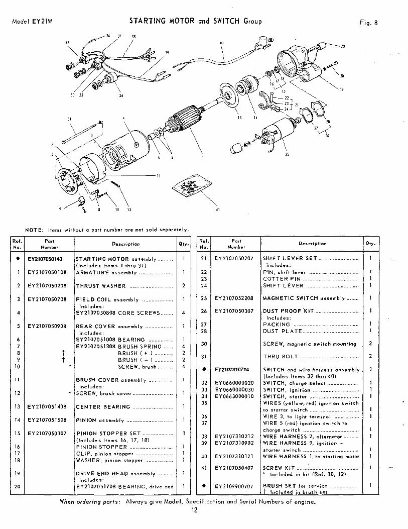
Mode I EY 21 W STARTING MOTOR and SWITCH Group Fig. 8
_, ~
d l IO 1 2
NOTE: Items without a part number are not sold seporately. - Ref. No.
21
22 23 24
25
26
-
27 28
30
31
0
32 33 34 35
36 37
38 39
40
41
e -
- 3ty.
1 -
1 1 1
1
1
1 1
2
2
1
1 1 1
1 1
1 1
1 1
1
1 -
7
Ref. Numbar No.
Port Description G Port
Number Description
SHIFT LEVER SET .......................... Includes:
PIN, shi f t lever ................................ C O T T E R P I N .................................... SHIFT LEVER ..................................
MAGNETIC SWITCH assembly ........
DUST PROOF 'KIT ........ ~ ...._.............. Includes:
PACKING .........__. .............................. DUST P L A T E ....................................
EY 2107050207 e
1
EY2107050140 STARTING MOTOR assembly .......... (Includes I tems 1 th ru 31)
EY2107050108 ARMATURE assembly .._.....__.._........_ 1
I 2 I EY2107050208 THRUST WASHER ............................ I I 2
EY2107052208
EY2107050307
1 3
4
EY2107050708
EY2107050808 C O R E SCREWS ........
FIELD COIL ossembly .._................. Includes:
EY2107050908 REAR COVER assembly .................. Includes:
EY2107051008 BEARING ................ EY2107051308 BRUSH SPRING ......
BRUSH ( + ) ..........._ t t BRUSH ( - ) ............
* SCREW, brush ,..........
BRUSH COVER assembly ._............._ Includes:
* SCREW, brush cover ........._.__...__.._...._
4
5 1
6 7 8 9
10
SCREW, mugnetic switch mounting
THRU BOLT ......................................
EY2107310714 SWITCH and wire horness assembly ( Includes I tems 32 th ru 40) SWITCH, charge select .__........__....... SWITCH, i gn i t i on .............................. SWITCH, starter ................................ WIRES (ye l low, red) ign i t ion swi tch to storter switch ................................ WIRE 3, to l ight terminal ._......_._..... WIRE 5 ( red) ign i t ion sw i tch to
charge switch .................................... WIRE HARNESS 2, alternotor .......... WIRE HARNESS 9, i gn i t ion -
WIRE HARNESS 1, to start ing motor starter switch ....................................
* Included in k i t (Ref . 10, 12) SCREW K I T ........................................
BRUSH SET for service .................. t Included in brush set
1 11
12
EY0660000020 EY 0660000030 EY0663000010
1
1 13 CENTER BEARING .._.__.....__..._........_ EY2107051408
14 PINION assembly .............................. EY2107051508 1
1 15
16 17 18
EY2107050107 PINION STOPPER SET ._.................. (Includes I tems 16, 17, 18) PINION STOPPER ............................ CLIP, pinion stopper ........................ WASHER, pinion stopper ..................
DRIVE END HEAD assembly ..........
EY2107051708 BEARING, drive end Includes:
EY2107310212 EY 21 073 10902
EY2107310121
EY 2 107050407 1 19
20 1 -
EY2109900707 i
W h en ordering ports: Always g i v e M o d e l , S p e c i f i c a t i o n a n d Ser ia l Numbers of engine.
12
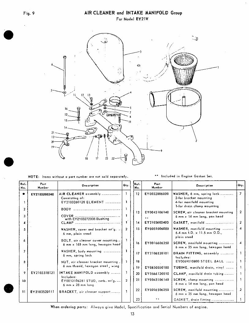
Fig. 9
- ?ef. No.
0
1
2
3
4
5
6
7
8
9
10
11
-
AIR CLEANER and INTAKE MANIFOLD Group For Model EY21W
NOTE: Items without a part number are not sold separately
Port Number
EY 21 03260240
EY2103310121
EY 21035201 11
Description
AIR CLEANER assembly .................... Consis t ing o f : EY2103260128 ELEMENT ................
BODY ..................................................
COVER ................................................
CLAMP ................................................ with EY2103272008 Bushing
WASHER, cover and bracket mt'g. .. 6 mm, p la in s tee l
BOLT, air cleaner cover mounting .... 6 mm x 165 mrn long, hexagon head
WASHER, body mounting .................. 6 mm, spr ing lock
NUT, air cleaner bracket mounting .. 6 mm threa'd, hexagon steel , wing
INTAKE MANIFOLD assembly .......... Includes: EY0013106281 STUD, carb. mt'g. .... 6 rnm x 28 mm long
BRACKET, air cleaner support ..........
- hy.
1
1
1
1
1 '
2
1
1
1
1
2
1
-
- Zef. 40.
12 -
13
14
15
16
17
18
19
20
21
22
23 -
** Included in Engine Gasket Set.
Part Number
EY 0032006000
EYO043106140
* * EY2103600403
EY0031006000
EY0016606350
EY2106530101
EY0850050100
EY0566120010
EYU043106140
EY0016506250
* *
Description
WASHER, 6 mm, spr ing lock .............. 2-for bracket mounting 4-for manifold mounting 1-for drain clamp mounting
SCREW, air cleaner bracket mounting
6 mm x 14 mm long, pan heod
GASKET, manifold ..............................
WASHER, manifold mounting ............ 6.4 mm I.D. x 11.5 mm O.D., p la in s tee l
SCREW, manifold mounting ................ 6 mm x 35 mm long, hexagon head
DRAIN FITTING, assembly .............. Includes: EY0069010800 STEEL BALL ........
TUBING, manifold drain, v inyl ........
CLAMP, manifold drain tubing .......... SCREW, clamp mounting ....................
6 rnm x 14 mm long, pon head
SCREW, manifold mounting ................ 6 mrn x 25 mm long, hexagon head
G A S K E T , d ra in f i t t i ng ........................
When ordering pa r t s : Always g ive Mode l , Spec i f i ca t i on and Se r ia l Numbers of engine.
13
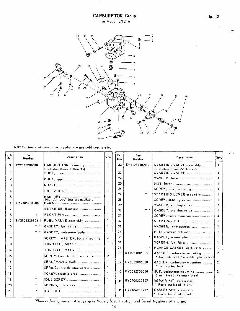
CARBURETOR Group For Model E Y 2 l W
Fig. 10
2
12
26
i 9 is 29 2; 2; 3 8 2
37
25
NOTE: I tems without a part number are not sold separately.
t I I I I I Part Number Description Ref.
No.
0
-
1
2
3
4
5
6
7
8
9
10
11
12
13
14
15
16
17
18
19
20
21
-
Ref. Number No.
Port Description Qty.
EY2106230800 CARBURETOR assembly .................. (Includes Items 1 thru 36) BODY, lower ......................................
BODY, upper ......................................
N O Z Z L E .............................................. IDLE A IR JET ....................................
"High Altitude" Jets are available MAIN JET
F L O A T ................................................ RETAINER, f loat p in ........................ F L O A T P I N ......................................... FUEL VALVE assembly ..................
GASKET, fuel va lve ..........................
GASKET, carburetor body ................ SCREW - WASHER, body attaching
THROTTLE SHAFT .......................... T H R O T T L E V A L V E ..........................
............................................
SCREW, throttle shaft and va lve ......
SEAL,'throttle shaft .......................... SPRING, throttle stop screw ............ SCREW, thrott le stop ........................
IDLE SCREW ...................................... SPRING, idle screw ..........................
I D L E J E T ............................................
i 1 22
23
EY2106230208 STARTING VALVE assembly ............ (Includes I tems 22 thru 29) STARTING VALVE ............................ I : I 1
1 1
1
1
1
1
1
1
1
1
1
4
1
1
2
1
1
1
1
1
1
-
.................................... I 24 I I WASHER, lever I 1 I NUT, lever ............................................ SCREW, lever mounting ...................... STARTING LEVER assembly ............ SCREW, start ing va lve ........................ WASHER, start ing valve .................... GASKET, starting valve .................... SCREW, va lve mounting ...................... STARTING JET ..................................
25
26
27
28
29
30
31
32
t
t * EY2106250508
t EY 2106230308 t
t * t *
........................ I 33 I I WASHER, jet mounting 1 1 I 34
35
36
37 38
39
40
0
0
-
PLUG, screen retainer ........................
2 WASHER, carburetor mounting .......... 1 FLANGE GASKET, carburetor .......... 1 SCREEN, fuel filter ............................ 1 GASKET, screen plug ........................ 1
6 . 4 m r n l . D . x 11.5mmO.D.,plainsteeI
WASHER, carburetor mounting .......... 2 6 mm, spr ing lock
NUT, carburetor mounting .................. 2 6 mm thread, hexogon s tee l
R E PA1 R KIT, carburetor t Parts included in k i t .
GASKET SET, carburetor * Parts included in set.
*
t * EY0031006000
EY0032006000
EY0022706000
EY2106230107
EY2106230207
I
When ordering par ts: Always g i v e Model, S p e c i f i c a t i o n and Ser ia l Numbers of engine.
14
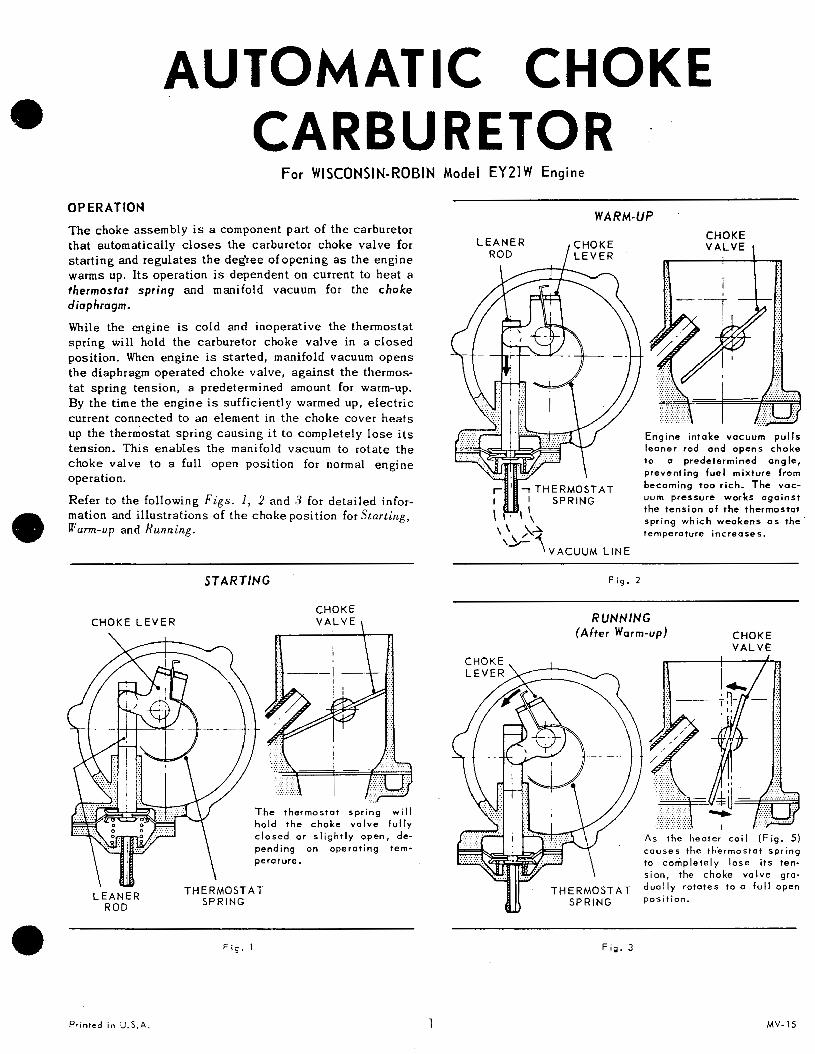
AUTOMATIC CHOKE CARBURETOR .
For WISCONSIN-ROBIN Model EY21W Engine
OPERATION WARM-UP
T h e c h o k e a s s e m b l y is a component part of the carbure tor tha t au tomat ica l ly c loses the carbure tor choke va lve for s ta r t ing and regula tes the degree o fopening a s t h e e n g i n e warms up. I ts operat ion is dependent on cur ren t to hea t a thermosta t spr ing and manifold vacuum for the choke diaphragm.
While the eng ine i s co ld and i nope ra t ive t he t he rmos ta t spr ing wil l hold the carburetor choke valve in a c l o s e d posi t ion. When eng ine i s s t a r t ed , man i fo ld vacuum opens the d iaphragm opera ted choke va lve , aga ins t the thermos- ta t spr ing tens ion , a predetermined amount for warm-up. By t he t ime t he eng ine i s su f f i c i en t ly warmed up , e l ec t r i c cur ren t connec ted to an e lement in the choke cover hea ts up the thermosta t spr ing caus ing i t to c o m p l e t e l y l o s e i t s t ens ion . This enables the mani fo ld vacuum to r o t a t e t h e c h o k e v a l v e t o a ful l open posi t ion for normal engine operation.
Refer to the following F i g s . 1, 2 and 3 for detailed infor- mat ion and i l lustrat ions of the choke posi t ion for SLart ing, ularm-up and Running.
CHOKE
the tension o f the thermostat spr ing which weakens a s t h e \' AA temperature increases.
'b- l V A C U U M L I N E
STARTING F i g . 2
CHOKE L E V E R CHOKE V A L V E 1 RUNNING
(After Warm-up) CHOKE V A L V E
F i g . 1 F i g . 3
Printed in U.S.A. 1 MV- 15
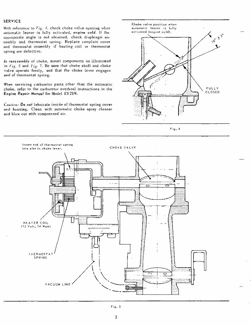
SERVICE C h o k e v a l v e p o s i t i o n w h e n
With reference to F i g . 4, check choke valve opening when a u t o m a t i c l e a n e r i s f u l l y automat ic l eaner i s fu l ly ac t iva ted , engine c o l d . If the appropr ia te angle is not obta ined , check d iaphragm as- sembly and thermostat spr ing. Replace complete cover and thermostat assembly if hea t ing co i l or thermostat s p r i n g are defect ive.
In reassembly of choke, mount components a s i l l u s t r a t e d in F i g . 5 and Fig. 7. Be su re t ha t choke sha f t and choke va lve opera te f ree ly , and tha t the choke lever engages end of thermostat spring.
When serv ic ing carbure tor par t s o ther than the au tomat ic choke, refer to the carburetor overhaul instruct ions in the Engine Repair Manual for Model EY21W.
Caution: Do not l ub r i ca t e i n s ide of thermostat spr ing cover and housing. Clean with automatic choke spray c leaner and blow out with compressed a i r .
F i g . 4
Inser t end of thermostat spring i n t o s l o t i n choke l e v e r . C H O K E V A L V E
H E A T E ( 1 2 V o l t .
T H E 5
”
Fig. 5
2
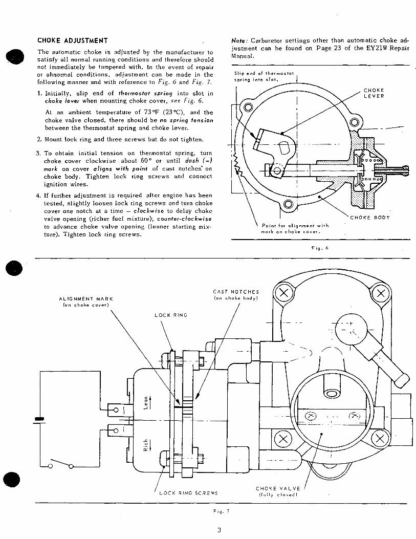
CHOKE ADJUSTMENT
T h e a u t o m a t i c c h o k e i s a d j u s t e d by the manufacturer to sa t i s fy a l l normal running condi t ions and therefore should not immediately be tampered with. In t h e e v e n t of repair or abnormal condi t ions, adjustment can be made in the. following manner and with reference to F i g . 6 and F i g . 7.
1. In i t i a l ly , s l i p end of thermostat spr ing into slot in choke lever when mounting choke cover, s e e Fig. 6.
A t an ambient temperature of 73OF (23"C), and the c h o k e v a l v e c l o s e d , t h e r e s h o u l d b e no spr ing tension between the thermosta t spr ing and choke lever .
2. Mount lock r ing and three screws but do not t ighten.
3. To obta in in i t ia l t ens ion on thermosta t spr ing , tu rn choke cove r c lockwise abou t 60" or unti l dash ( -1 mark on cover a l i g n s w i t h p o i n t of cast notches ' on choke body. Tighten lock r ing screws and connect ignition wires.
4. If fur thet adjustment is required af ter engine has been t e s t ed , s l i gh t ly l oosen l ock r i ng s c rews and t u r n c h o k e cover one notch a t a t ime - c l o c k w i s e t o de l ay choke valve opening (richer fuel mixture); c o u n t e r - c l o c k w i s e to advance choke va lve opening ( leaner s ta r t ing mix- ture) . Tighten lock r ing screws.
Note: Carbure tor se t t ings o ther than au tomat ic choke ad- jus tment can be found on Page 23 of t h e EY21W Repair Manual.
Sl ip end of thermostot
\ I ' C H O K E B O D Y
P o i n t f o r a l i g n m e n t w i t h . '
mark on c h o k e c o v e r .
F i g . 6
'LOCK RING SCREWS C H O K E V A L V E 1
( f u f l y c l o s e d )
F i g . 7
3
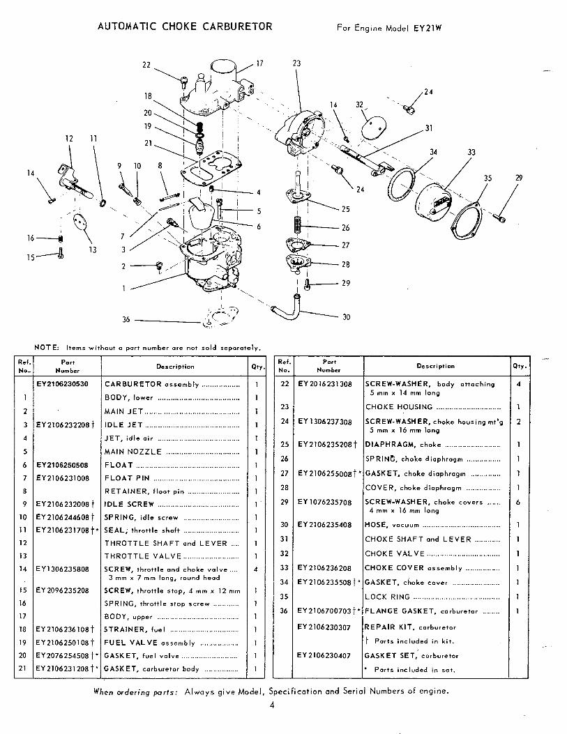
AUTOMATIC CHOKE CARBURETOR For Eng ine Mode l E Y 2 l W
12 11
\
- ?ef. No. -
1
2
3
4
5
6
7
8
9
10
11
12
13
14
15
16
17
18
19
20
21 -
NOTE: I tems without a part number are not sold separately.
Part Number
EY2106230530
EY2106232208t
EY2106250508
EY2106231008
EY2106232008t
EY 2106244608 t EY2106231708t l
EY 1306235808
EY 2096235208
EY2106236108t
EY2106250108t
EY2076254508 t* EY 2106231 208 t *
Description
CARBURETOR assembly ............_...._ BODY, lower ...................................... MAIN JET ............................................ IDLE J E T ............................................ JET, id le a i r ...................................... MAIN NOZZLE .................................. F L O A T ................................................ F L O A T P I N ........................................ RETAINER, float pin ........................ I D L E SCREW ...................................... SPRING, idle screw .......................... SEAL; throttle shaft .._..._...__._____________ THROTTLE SHAFT ond L E V E R ..._ T H R O T T L E V A L V E .......................... SCREW, throttle and choke v a l v e ....
3 rnm x 7 m m long, round head
SCREW, throttle stop, 4 mm x 12 mm
SPRING, thrott le s top screw .._.........
BODY, upper ...................................... STRAINER, fuel ................................
FUEL VALVE assembly ..............._.. GASKET, fuel v a l v e .......................... GASKET, carburetor body ......_.........
- Q Y
1
1
1
1
1
1
1
1
1
1
1
1
1
1
4
-
1
1
1
1
1
1
1 -
- Ref . No.
22 -
23
24
25
26
27
28
29
30
31
32
33
34
35
36
-
Part Number
EY 2016231308
EY 1306237308
EY 2106235208t
EY2106255008t’
EY 1076235708
EY 2106235408
EY2106236208
EY2106235508t*
EY2106700703t’
EY 2106230307
EY 2106230407
Description
SCREW-WASHER, body attaching 5 mm x 14 mrn long
CHOKE HOUSING ..............................
SCREW-WASHER, choke housing mt’g 5 mm x 16 mrn long
DIAPHRAGM, choke ..........................
SPRINC, choke diaphragm .._.._.._....._.
GASKET, choke diaphragm _...__........ COVER, choke diaphragm ................
SCREW-WASHER, choke covers _..._. 4 mm x 16 mm long
HOSE, vacuum ......................... ~ ____...._.
CHOKE SHAFT and LEVER ............
CHOKE VALVE ....._......._ ~ ._......_.._._.._..
CHOKE COVER assembly ._..._..........
GASKET, choke cover _______...____.___.___
LOCK RING ........................................
FLANGE GASKET, carburetor ........
REPAIR KIT, carburetor
f’ Parts included in kit .
GASKET SET, carburetor
‘ Parts included in set.
- a t Y - 4
1
2
1
1
1
1
6
1
1
1
1
1
1
1
When order ing p o r t s : Always g i v e Model, Spec i f i ca t ion and Ser ia l Numbers of engine.
4