world journal of radiology - .net framework
TRANSCRIPT

World Journal ofRadiology
World J Radiol 2019 July 28; 11(7): 94-109
ISSN 1949-8470 (online)
Published by Baishideng Publishing Group Inc
W J R World Journal ofRadiology
Contents Monthly Volume 11 Number 7 July 28, 2019
ORIGINAL ARTICLE
Retrospective Study
94 Genial tubercles: Morphological study of the controversial anatomical landmark using cone beam computed
tomographyAraby YA, Alhirabi AA, Santawy AH
Observational Study
102 Y90-radioembolization via variant hepatic arteries: Is there a relevant risk for non-target embolization?Zimmermann M, Schulze-Hagen M, Pedersoli F, Isfort P, Heinzel A, Kuhl C, Bruners P
WJR https://www.wjgnet.com July 28, 2019 Volume 11 Issue 7I
ContentsWorld Journal of Radiology
Volume 11 Number 7 July 28, 2019
ABOUT COVER Editorial Board Member of World Journal of Radiology, Giulia A Zamboni,MD, Attending Doctor, Doctor, Staff Physician, Institute of Radiology,Azienda Ospedaliera Universitaria Integrata di Verona, Verona 37134,Verona, Italy
AIMS AND SCOPE World Journal of Radiology (World J Radiol, WJR, online ISSN 1949-8470, DOI:10.4329) is a peer-reviewed open access academic journal that aims to guideclinical practice and improve diagnostic and therapeutic skills of clinicians. The WJR covers topics concerning diagnostic radiology, radiationoncology, radiologic physics, neuroradiology, nuclear radiology, pediatricradiology, vascular/interventional radiology, medical imaging achieved byvarious modalities and related methods analysis. The current columns ofWJR include editorial, frontier, mini-reviews, review, medical ethics,original articles, case report, etc. We encourage authors to submit their manuscripts to WJR. We will givepriority to manuscripts that are supported by major national andinternational foundations and those that are of great basic and clinicalsignificance.
INDEXING/ABSTRACTING The WJR is now abstracted and indexed in Emerging Sources Citation Index (Web of
Science), PubMed, PubMed Central, China National Knowledge Infrastructure
(CNKI), China Science and Technology Journal Database (CSTJ), and Superstar
Journals Database.
RESPONSIBLE EDITORS FORTHIS ISSUE
Responsible Electronic Editor: Yu-Jie Ma
Proofing Production Department Director: Yun-Xiaojian Wu
NAME OF JOURNALWorld Journal of Radiology
ISSNISSN 1949-8470 (online)
LAUNCH DATEJanuary 31, 2009
FREQUENCYMonthly
EDITORS-IN-CHIEFVenkatesh Mani
EDITORIAL BOARD MEMBERShttps://www.wjgnet.com/1949-8470/editorialboard.htm
EDITORIAL OFFICEJin-Lei Wang, Director
PUBLICATION DATEJuly 28, 2019
COPYRIGHT© 2019 Baishideng Publishing Group Inc
INSTRUCTIONS TO AUTHORShttps://www.wjgnet.com/bpg/gerinfo/204
GUIDELINES FOR ETHICS DOCUMENTShttps://www.wjgnet.com/bpg/GerInfo/287
GUIDELINES FOR NON-NATIVE SPEAKERS OF ENGLISHhttps://www.wjgnet.com/bpg/gerinfo/240
PUBLICATION MISCONDUCThttps://www.wjgnet.com/bpg/gerinfo/208
ARTICLE PROCESSING CHARGEhttps://www.wjgnet.com/bpg/gerinfo/242
STEPS FOR SUBMITTING MANUSCRIPTShttps://www.wjgnet.com/bpg/GerInfo/239
ONLINE SUBMISSIONhttps://www.f6publishing.com
© 2019 Baishideng Publishing Group Inc. All rights reserved. 7041 Koll Center Parkway, Suite 160, Pleasanton, CA 94566, USA
E-mail: [email protected] https://www.wjgnet.com
WJR https://www.wjgnet.com July 28, 2019 Volume 11 Issue 7II
W J R World Journal ofRadiology
Submit a Manuscript: https://www.f6publishing.com World J Radiol 2019 July 28; 11(7): 94-101
DOI: 10.4329/wjr.v11.i7.94 ISSN 1949-8470 (online)
ORIGINAL ARTICLE
Retrospective Study
Genial tubercles: Morphological study of the controversialanatomical landmark using cone beam computed tomography
Yasser A Araby, Ahmed A Alhirabi, Abdelaleem H Santawy
ORCID number: Yasser A Araby(0000-0002-5340-5875); Ahmed AAlhirabi (0000-0002-3663-3999);Abdelaleem H Santawy(0000-0001-7506-9561).
Author contributions: Araby YA,Alhirabi AA and Santawy AHcontributed equally to this work;Araby YA conceived and designedresearch; Alhirabi AA and SantawyAH collected data; Araby YA,Alhirabi AA and Santawy AHanalyzed data; Araby YA andAlhirabi AA wrote the paper withthe support of Santawy AH.
Institutional review boardstatement: The study protocol wasreviewed and conducted withapproval by the Ethical Committee,Dental Research Center, College ofDentistry, Qassim University,Saudi Arabia.
Informed consent statement:Patients were not required to giveinformed consent to the studybecause the analysis usedanonymous data that wereobtained from the RadiologyDepartment Archive, DentalClinics Center, Qassim University,KSA after each patient agreed totreatment by written consent.
Conflict-of-interest statement: Allauthors declare that they have noconflicts of interest.
Open-Access: This article is anopen-access article which wasselected by an in-house editor andfully peer-reviewed by externalreviewers. It is distributed inaccordance with the CreativeCommons Attribution NonCommercial (CC BY-NC 4.0)
Yasser A Araby, Department of Prosthetic Dental Sciences, College of Dentistry, QassimUniversity, Qassim 51452, Saudi Arabia
Ahmed A Alhirabi, Dental Intern, College of Dentistry, Qassim University, Qassim 51452,Saudi Arabia
Abdelaleem H Santawy, Department of Maxillofacial Surgery and Diagnostic Sciences, Collegeof Dentistry, Qassim University, Qassim 51452, Saudi Arabia
Corresponding author: Yasser A Araby, BSc, MSc, PhD, Lecturer, Department of ProstheticDental Sciences, College of Dentistry, Qassim University, Burayadh, Qassim 51452, SaudiArabia. [email protected]: +966-5-30488300Fax: +966-1-63801761
AbstractBACKGROUNDIdentification of the morphology of the genial tubercles (GTs) is valuable fordifferent dental applications. The morphological pattern of the GTs is stillcontroversial, and therefore, the study of its morphology using cone beamcomputed tomography (CBCT) plays a valuable role in resolving the controversy.
AIMTo assess the morphological pattern, dimensions and position of the GTs usingCBCT among a selected Saudi population.
METHODSCBCT records of 155 Saudi subjects (49 female and 106 male) were used to assessthe pattern and size of the GTs and to determine the distance from the apices ofthe lower central incisors to the superior border of the incisors (I-SGT) and thedistance from the inferior border of the GTs to the menton (IGT-M).
RESULTSThe results of this study showed that the most common morphological patternwas of two superior GTs and a rough impression below them (36.8%), followedby two superior GTs and a median ridge representing fused inferior GTs belowthem (22.6%) and a single median eminence or projection (20%). The classicallydescribed pattern, of two superior and two inferior GTs placed one above theother, was found in only 14.2% of cases, while 6.4% of the studied cases had noGTs. The mean width and height were 6.23 ± 1.93 mm and 6.67 ± 3.04 mm,respectively, while the mean I-SGT and IGT-M measurements were 8.26 ± 2.7 mm
WJR https://www.wjgnet.com July 28, 2019 Volume 11 Issue 794
license, which permits others todistribute, remix, adapt, buildupon this work non-commercially,and license their derivative workson different terms, provided theoriginal work is properly cited andthe use is non-commercial. See:http://creativecommons.org/licenses/by-nc/4.0/
Manuscript source: Unsolicitedmanuscript
Received: April 23, 2019Peer-review started: May 8, 2019First decision: June 17, 2019Revised: July 9, 2019Accepted: July 25, 2019Article in press: July 25, 2019Published online: July 28, 2019
P-Reviewer: Gao BLS-Editor: Cui LJL-Editor: AE-Editor: Ma YJ
and 8.13 ± 3.07 mm, respectively.
CONCLUSIONThe GTs are a controversial anatomical landmark with wide variation in theirmorphological pattern. The most common pattern among the studied Saudisample was of two superior GTs and a rough impression below them, and therewere no significant differences between males and females.
Key words: Genial tubercles; Cone beam computed tomography; Morphological analysis;Mandible; Anatomical landmark
©The Author(s) 2019. Published by Baishideng Publishing Group Inc. All rights reserved.
Core tip: The morphological pattern of the genial tubercles (GTs) is controversial.Classically, they are described as four elevations equidistant between the upper andlower edges of the mandible that are arranged in pairs and surround the lingual foraminabilaterally; however, several osteological and radiological studies proved that there iswide variation in their morphology. This retrospective study was conducted to determinethe morphological pattern, size and position of the GTs using cone beam computedtomography among a selected Saudi population.
Citation: Araby YA, Alhirabi AA, Santawy AH. Genial tubercles: Morphological study of thecontroversial anatomical landmark using cone beam computed tomography. World J Radiol2019; 11(7): 94-101URL: https://www.wjgnet.com/1949-8470/full/v11/i7/94.htmDOI: https://dx.doi.org/10.4329/wjr.v11.i7.94
INTRODUCTIONGenial tubercles (GTs), also known as spinae mentalis, genial apophysis and mentalspines GTs are small eminences of bone found on the lingual side of the mandible atthe midline and are important landmarks for maxillofacial surgeons, radiologists,prosthodontists and general dentists[1,2].
The GTs serve as the insertion of the geniohyoid muscles in the lower and thegenioglossus muscles in the upper portions of the tubercles. The action of thesemuscles is related to tongue mobility and swallowing, which are important for speechand feeding[3].
Although the genial tubercles are classically described in different anatomytextbooks as four mental spines on the lingual surface of the symphysis mentiarranged in two pairs placed one above the other, they show different patterns intheir positions and shapes[4,5].
Cone beam computed tomography (CBCT) is an accurate method to evaluate themorphology, size and position of the GTs[6,7].
Accurate identification of the GTs morphology, size and/or position using three-dimensional (3D) imaging is valuable for different applications, such as preparationfor genioglossus advancement in the treatment of obstructive sleep apnea[8,9],estimation of the safe zone before implant surgery in the interforaminal region of themandible[6] and evaluation of mandibular asymmetry on CBCT images[10].
In cases of extreme atrophy of the aged edentulous mandibles, when the GTsremain as bony projections in the floor of the mouth, they can pose a greatprosthodontic challenge[11-13].
In this context, it is very important to identify the morphology of the GTs and theirrelation to the mandibular anterior teeth and to the margins of the mandible.
In the literature, there is no study describing the morphology of the GTs among theSaudi population; thus, the aim of this study is to determine the morphologicalpattern, size and position of the GTs using CBCT among a selected Saudi population.
MATERIAL AND METHODS
Study design
WJR https://www.wjgnet.com July 28, 2019 Volume 11 Issue 7
Araby YA et al. Genial Tubercles: Controversial anatomical landmark
95
CBCT images used in this study were obtained from the Radiology DepartmentArchive of the Dental Clinics Center, Qassim University, and the study protocol wasapproved by the Ethical Committee of the Dental Research Center, College ofDentistry, Qassim University, Saudi Arabia.
The inclusion criteria included patients from both sexes, above the age of 17 yearsand with full anterior dentition. The exclusion criteria included completelyedentulous patients; patients with missing anterior teeth or those with mandibularasymmetry, congenital or developmental deformities; patients with traumatic injuryor pathologic changes in the mandible; and patients with blurred or distorted CBCTimages.
CBCT images were acquired using the Galileos® Comfort plus System (Sirona 3D,Germany) with settings as follows: X-ray generator, 98 kV and 3-6 mA. Focal spot sizeaccording to IEC 60336 was 0.5 mm, and the total filtration according to IEC 60522was > 2.5 mm. The detector was an Image Intensifier by Siemens with the followingsettings: Pixels: 1000; FPS: 15-30; dynamics: 12 Bits; image volume: 15.4 cm, sphericalvolume – collimated 15 cm × 8.5 cm; voxel size 0.25/0.125 mm; scan time/exposuretime 14 s/2-5 s. Galileos software was used, which allowed linear measurements ofimages and detection of the GT pattern.
CBCT scans were oriented to standardize the measurements so that the bilateralzygomatic structures were at the same level in the axial view. The infra orbitalforamina of the right and left sides were parallel to the horizontal line in the coronalview. In the sagittal view, the Frankfort plane represented the true horizontal axis.
To reduce measurement error, all measurements were repeated on 2 separateoccasions in 1-wk intervals, and the average values were recorded. Differencesbetween the 2 readings were used to assess intra examiner variation with a paired t-test.
GTs pattern assessmentThe morphological patterns of the GTs were studied and grouped into five patterns asfollows: The classic description of four spines, two superior and two inferior tubercles(Type I); two superior GTs and a median ridge representing fused inferior GTs belowthem (Type II); two superior GTs and a rough impression below them (Type III); asingle median eminence or projection (Type IV); and absence of the GTs (Type V). Thepattern of the GTs was evaluated in the axial view, together with the sagittal view.(Figure 1).
GTs position and size assessmentThe following parameters were measured in millimeters: GTs height (GTH), GTswidth (GTW), distance from the superior border of the GTs to the apex of the lowercentral incisors (I-SGT) and the distance from the inferior border of the GTs to thementon (IGT-M).
GTW was measured in the axial view at the level of the widest level of the GTs,while GTH was measured in the sagittal view as the vertical distance between thelevel of the most superior and the most inferior borders of the GTs.
I-SGT and IGT-M were measured by drawing tangential lines from the apex of thelower central incisors to the superior border of the GTs and from the inferior border ofthe GTs to the inferior border of the mandible (menton), respectively (Figure 2).
Statistical analysisThe collected data were tabulated and analyzed using SPSS 20.0 (Statistical Packagefor Scientific Studies) for Windows. A paired t-test was used for intra examinercalibration, and a chi square test was used for comparison between genial tuberclepatterns in both sexes. All statistical tests were adjusted at a significance level of P <0.05.
RESULTSThe data were collected from 155 Saudi patients aged 17 to 63 years of both sexes,who were treated at the Dental Clinics Center of Qassim University and fulfilled theinclusion and exclusion criteria. The sex distribution was 106 (69.4%) males and 49females (31.6%). The intraexaminer reliability showed no statistically significantdifference between the 2 image readings by using a paired t-test (P > 0.05) and hadalmost perfect agreement (P = 0.92 for the measurements and P = 0.94 for the patterndistribution).
Regarding the pattern distribution of the GTs among the selected sample (Table 1and Figure 3), Type III (36.8%) was the most common pattern, followed by Type II(22.6%), Type IV (20%) and Type I (14.2%), while Type V was the least common
WJR https://www.wjgnet.com July 28, 2019 Volume 11 Issue 7
Araby YA et al. Genial Tubercles: Controversial anatomical landmark
96

Figure 1
Figure 1 Detection of the genial tubercles pattern in the sagittal and axial views.
among the pattern types (6.4%). Regarding the correlation of the pattern of the GTswith sex, there was no statistically significant difference between sexes at P ≤ 0.05using the chi-square test.
The GTH and GTW as well as the distance from the GTs superior border to theapices of the I-SGT and the distance from the inferior border of the GTs to theIGT-Mare tabulated in Table 2.
The mean GTH measured was 6.67 ± 3.04 mm, and the mean GTW was 6.23 ± 1.93mm. The average I-SGT was 8.26 ± 2.7 mm, and the average IGT-M was 8.13 ± 3.07mm.
DISCUSSIONThe main advantages of CBCT are accessibility, ease of handling, and availability ofin-office imaging, and it offers a real-size dataset with multiplanar cross-sectional and3-dimensional reconstructions from a single scan with a low radiation dose andrelatively low cost compared with conventional computed tomography[14].
Several studies demonstrated an acceptable accuracy of linear measurements ofalveolar bone and mandibular anatomy in CBCT[15]. The results of a study conductedby Hueman et al[9] showed the accuracy of CBCT in identifying the anatomic locationof the GTs. Therefore, we used CBCT to explore the morphological pattern,dimensions and position of this important landmark.
The morphological pattern of the GTs is controversial and debated; classically, it isdescribed as four elevations equidistant between the upper and lower edges of themandible that are arranged in pairs and surround the lingual foramina bilaterally.However, several osteological and radiological studies proved that there is widevariation in their morphology.
Regarding the GTs pattern distribution among our selected sample, Type III wasthe most common type, and type V was the least common type, indicating that type I(the classic pattern) is not the most common type. This observation was alsopreviously described in 2 osteological studies, one conducted among the Indianpopulation by Singh et al[4] and one conducted among the Brazilian population by Odaet al[5].
The results of the width and height measurements of our study were 6.23 ± 1.93mm and 6.67 ± 3.04 mm, respectively, which is in line with the results of theradiological study conducted by Wang et al[7], who examined the CBCT records ofninety Taiwanese patients and stated that the ranges of GTH measurements were 6.5-7.9 mm and the ranges of the GTW measurements were 7.1-8.2 mm. This is also in linewith the study conducted by Yin et al[16], who studied the morphometry of GTs in theChinese population with both anatomical and imaging techniques and correlatedthem. He concluded that the height and width of the GTs, which were measured byspiral computed tomography, were 6.17 ± 0.71 mm and 7.01 ± 1.13, respectively.
The IGT-M measurements in our study (8.13 ± 3.07 mm) were in line with themeasurements made by Hueman et al[9] (11.2 ± 3.6 mm), who measured the distancefrom the middle part of the tubercle to the menton.
The mean I-SGT measurement in our study was 8.26 ± 2.7 mm, and a similar resultwas discussed by Kolsuz et al[17], who studied the anatomy of the genial tubercle usingCBCT among a Turkish sample population and found that the mean I-SGT was 8.1 ±1.7 mm in males and 7.7 ± 1.8 in females with class I occlusion.
In conclusion, the morphological pattern of the GTs is controversial; the GTs are
WJR https://www.wjgnet.com July 28, 2019 Volume 11 Issue 7
Araby YA et al. Genial Tubercles: Controversial anatomical landmark
97

Figure 2
Figure 2 Measurements of the genial tubercle height, distance from the superior border of the genial tubercles to the apex of the lower central incisorsand the distance from the inferior border of the genial tubercles to the mentonin the sagittal view and genial tubercles width in the axial view. GTH: Genialtubercles height; GTW: Genial tubercles width; I-SGT: Lower central incisors; IGT-M: Genial tubercles to the menton.
classically described as four elevations equidistant between the upper and loweredges of the mandible that are arranged in pairs, but this is not the most commonpattern. The most common pattern among the studied Saudi sample population is oftwo superior GTs and a rough impression below them with no significant differencebetween males and females. Further studies should be conducted with larger samplesizes to obtain an accurate morphological analysis of the GTs among different ethnicgroups.
WJR https://www.wjgnet.com July 28, 2019 Volume 11 Issue 7
Araby YA et al. Genial Tubercles: Controversial anatomical landmark
98

Table 1 Genial tubercles pattern distribution as a function of sex
Type
GenderTotal
Male (n = 106) (% = 32%) Female (n = 49) (% = 68%)
No % No % No %
I 14 13.20% 8 16.30% 22 14.20%
II 24 22.60% 11 22.40% 35 22.60%
III 39 36.80% 18 36.70% 57 36.80%
IV 23 21.70% 8 16.30% 31 20%
V 6 5.70% 4 8.20% 10 6.40%
χ2 = 1.0391, P = 0.9
Table 2 Dimensions of the genial tubercles
Dimensions Mean ± SD Maximum Minimum
GTH (mm) 6.67 ± 3.04 16.08 2.34
GTW (mm) 6.23 ± 1.93 11.77 1.8
I-SGT (mm) 8.26 ± 2.7 15.82 1.57
IGT-M (mm) 8.13 ± 3.07 14.9 1.31
GTH: Genial tubercles height; GTW: Genial tubercles width; I-SGT: Lower central incisors; IGT-M: Genial tubercles to the menton.
Figure 3
Figure 3 Genial tubercles pattern distribution.
ARTICLE HIGHLIGHTSResearch backgroundThe genial tubercles (GTs) are an important anatomical landmark that is located in the midline ofthe lingual side of the mandible and is important for multiple clinical and surgical interventions.For years, it was described as four spines arranged in two pairs, one above the other, and fewosteological and radiological studies demonstrated the wide variation in its morphology. conebeam computed tomography (CBCT) is an effective and simple method to use in the assessmentof GTs morphology among different ethnic groups.
Research motivationTo the best of our knowledge, no previous studies have assessed the pattern of GTs using CBCT,and no previous studies have assessed the dimensions and position of the GTs among the Saudipopulation or any other Arab population using either osteological or radiological methods.
Research objectivesThe aim of this study was to assess the pattern, size and position of the GTs using CBCT amonga selected Saudi population.
Research methodsWe used CBCT images of 155 male and female Saudi subjects who fulfilled the inclusion andexclusion criteria for this study. Galileos software was used to assess the GTs pattern and to
WJR https://www.wjgnet.com July 28, 2019 Volume 11 Issue 7
Araby YA et al. Genial Tubercles: Controversial anatomical landmark
99
collect all the linear measurements required to determine its dimensions and position in relationto the menton and the apices of the mandibular central incisors.
Research resultsOf the 155 studied subjects, 106 were males, and 49 were females; ages ranged from 17 to 63years. According to the analysis of the pattern of the GTs , we found that the prevalence of TypeIII was 36.8%, followed by Type II (22.6%) and Type IV (20%), while the classically describedpattern (Type I) was 14.2%. Type V was the least common among the pattern types (6.4%). Therewas no statistically significant difference between the sexes. Regarding its dimensions andposition, we found that the mean GTs height was 6.67 ± 3.04 mm, the mean width was 6.23 ± 1.93mm, and the average distance from the apices of the mandibular central incisors to its superiorborder was 8.26 ± 2.7 mm. the average distance between the GTs inferior border and the mentonwas 8.13 ± 3.07 mm.
Research conclusionsThe morphological pattern of the GTs is controversial; the classically described GTs pattern offour elevations, equidistant between the upper and lower edges of the mandible, that arearranged in pairs, is not the most common pattern. The most common pattern among the studiedSaudi sample was of two superior GTs and a rough impression below them with no significantdifference between the sexes.
Research perspectivesOur results suggest that CBCT might be a simple, valuable and effective tool for conducting anaccurate morphological analysis of the GTs among different ethnic groups and resolving thecontroversy about their morphology.
ACKNOWLEDGEMENTSThe authors would like to thank the College of Dentistry, Qassim University, SaudiArabia, for providing the radiographic records and the approval of this study.
REFERENCES1 Thomson A. On the Presence of Genial Tubercles on the Mandible of Man, and their Suggested
Association with the Faculty of Speech. J Anat Physiol 1915; 50: 43-74 [PMID: 17233052]2 Mintz SM, Ettinger AC, Geist JR, Geist RY. Anatomic relationship of the genial tubercles to the dentition
as determined by cross-sectional tomography. J Oral Maxillofac Surg 1995; 53: 1324-1326 [DOI:0278-2391(95)90594-4]
3 Ryan JM, Ross D, Obeid G. Genial tubercle fracture: a case report and review of the literature. J OralMaxillofac Surg 2010; 68: 2338-2341 [PMID: 20576336 DOI: 10.1016/j.joms.2010.02.032]
4 Singh V, Anand MK, Dinesh K. Variations in the pattern of mental spines and spinous mental foramina indry adult human mandibles. Surg Radiol Anat 2000; 22: 169-173 [PMID: 11143309 DOI:10.1007/s00276-000-0169-1]
5 Oda LS, Iyomasa MM, Watanabe IS. Morphologic analysis of the "spina mentalis" in adult mandibles ofBrazilian whites and negroes. Rev Bras Pesqui Med Biol 1977; 10: 357-360 [PMID: 609772]
6 Voon YS, Patil PG. Safe zone in anterior mandible related to the genial tubercle for implant osteotomy in aChinese-Malaysian population: A CBCT study. J Prosthet Dent 2018; 119: 568-573 [PMID: 28838820DOI: 10.1016/j.prosdent.2017.05.011]
7 Wang YC, Liao YF, Li HY, Chen YR. Genial tubercle position and dimensions by cone-beamcomputerized tomography in a Taiwanese sample. Oral Surg Oral Med Oral Pathol Oral Radiol 2012;113: e46-e50 [PMID: 22668717 DOI: 10.1016/j.oooo.2011.11.021]
8 Barbick MB, Dolwick MF. Genial tubercle advancement for obstructive sleep apnea syndrome: amodification of design. J Oral Maxillofac Surg 2009; 67: 1767-1770 [PMID: 19615597 DOI:10.1016/j.joms.2009.03.051]
9 Hueman EM, Noujeim ME, Langlais RP, Prihoda TJ, Miller FR. Accuracy of cone beam computedtomography in determining the location of the genial tubercle. Otolaryngol Head Neck Surg 2007; 137:115-118 [PMID: 17599577 DOI: 10.1016/j.otohns.2007.02.035]
10 Lee SY, Choi DS, Jang I, Song GS, Cha BK. The genial tubercle: A prospective novel landmark for thediagnosis of mandibular asymmetry. Korean J Orthod 2017; 47: 50-58 [PMID: 28127539 DOI:10.4041/kjod.2017.47.1.50]
11 Păuna MR, Babiuc I, Farcaşiu AT. Prosthodontic management of an extreme atrophy of the mandiblecorrelated with a prominent genial tubercle - a clinical report. Rom J Morphol Embryol 2015; 56: 867-870[PMID: 26429188]
12 Solomon EG. A critical analysis of complete denture impression procedures: contribution of earlyprosthodontists in India-part I. J Indian Prosthodont Soc 2011; 11: 172-182 [PMID: 22942577 DOI:10.1007/s13191-011-0089-2]
13 Shohat I, Shoshani Y, Taicher S. Fracture of the genial tubercles associated with a mandibular denture: aclinical report. J Prosthet Dent 2003; 89: 232-233 [PMID: 12644795 DOI: 10.1067/mpr.2003.46]
14 Fatemitabar SA, Nikgoo A. Multichannel computed tomography versus cone-beam computedtomography: linear accuracy of in vitro measurements of the maxilla for implant placement. Int J OralMaxillofac Implants 2010; 25: 499-505 [PMID: 20556248]
15 Ludlow JB, Laster WS, See M, Bailey LJ, Hershey HG. Accuracy of measurements of mandibularanatomy in cone beam computed tomography images. Oral Surg Oral Med Oral Pathol Oral RadiolEndod 2007; 103: 534-542 [PMID: 17395068 DOI: 10.1016/j.tripleo.2006.04.008]
WJR https://www.wjgnet.com July 28, 2019 Volume 11 Issue 7
Araby YA et al. Genial Tubercles: Controversial anatomical landmark
100

16 Yin SK, Yi HL, Lu WY, Guan J, Wu HM, Cao ZY, Yu DZ, Huang YY, Wu CG. Anatomic and spiralcomputed tomographic study of the genial tubercles for genioglossus advancement. Otolaryngol HeadNeck Surg 2007; 136: 632-637 [PMID: 17418264 DOI: 10.1016/j.otohns.2006.10.034]
17 Kolsuz ME, Orhan K, Bilecenoglu B, Sakul BU, Ozturk A. Evaluation of genial tubercle anatomy usingcone beam computed tomography. J Oral Sci 2015; 57: 151-156 [PMID: 26062865 DOI:10.2334/josnusd.57.151]
WJR https://www.wjgnet.com July 28, 2019 Volume 11 Issue 7
Araby YA et al. Genial Tubercles: Controversial anatomical landmark
101
W J R World Journal ofRadiology
Submit a Manuscript: https://www.f6publishing.com World J Radiol 2019 July 28; 11(7): 102-109
DOI: 10.4329/wjr.v11.i7.102 ISSN 1949-8470 (online)
ORIGINAL ARTICLE
Observational Study
Y90-radioembolization via variant hepatic arteries: Is there a relevantrisk for non-target embolization?
Markus Zimmermann, Maximilian Schulze-Hagen, Federico Pedersoli, Peter Isfort, Alexander Heinzel,Christiane Kuhl, Philipp Bruners
ORCID number: MarkusZimmermann(0000-0002-2632-800X); MaximilianSchulze-Hagen(0000-0002-9182-2688); FedericoPedersoli (0000-0001-5870-9299);Peter Isfort (0000-0002-0978-8995);Alexander Heinzel(0000-0002-2430-4557); ChristianeKuhl (0000-0001-8696-2363); PhilippBruners (0000-0002-5790-3687).
Author contributions:Zimmermann M, Schulze-HagenM, Isfort P, Kuhl C and Bruners Pcontributed to study conceptionand design; Zimmermann M,Pedersoli F and Heinzel Acontributed to data acquisition,data analysis and interpretation,and writing of article;Zimmermann M, Schulze-HagenM, Pedersoli F, Heinzel A, Isfort P,Kuhl C and Bruners P contributedto editing, reviewing and finalapproval of article.
Institutional review boardstatement: Approval for thisretrospective study was granted bythe institutional review board,internal reference number: EK308/18.
Informed consent statement: Theneed for informed consent waswaived by the institutional reviewboard due to the retrospectivestudy design and use of fullyanonymized patient data.
Conflict-of-interest statement: Onbehalf of all authors, thecorresponding author states thatthere is no conflict of interest.
Markus Zimmermann, Maximilian Schulze-Hagen, Federico Pedersoli, Peter Isfort, ChristianeKuhl, Philipp Bruners, Department of Diagnostic and Interventional Radiology, RWTH AachenUniversity Hospital, Aachen 52074, Germany
Alexander Heinzel, Department of Nuclear Medicine, RWTH Aachen University Hospital,Pauwelsstrasse 30, Aachen 52074, Germany
Corresponding author: Markus Zimmermann, MD, Attending Doctor, Department ofDiagnostic and Interventional Radiology, University Hospital RWTH Aachen, Pauwelsstr 30,Aachen 52074, Germany. [email protected]: +49-241-8037443Fax: +49-241-8082411
AbstractBACKGROUNDThe hepatic arterial anatomy is highly variable, with the two most commonvariants being a replaced right hepatic artery (RHA) originating from thesuperior mesenteric artery (SMA) and a left hepatic artery (LHA) originatingfrom the left gastric artery (LGA). These anatomical variants could potentiallyincrease the risk for non-target embolization during Y90-Radioembolization dueto the close proximity between hepatic and enteric vessel branches.
AIMTo evaluate the safety of Yttrium-90 radioembolization (90Y-RE) with resinmicrospheres in patients with a variant hepatic arterial anatomy.
METHODSIn this retrospective single-center observational study, 11 patients whounderwent RE with 90Y-resin microspheres via a LHA originating from the LGA,and 13 patients via a RHA originating from the SMA were included. Patient andtreatment data were reviewed regarding clinical and imaging evidence of non-target embolization of 90Y-resin microspheres to the GI tract. Positioning of the tipof the microcatheter in relationship to the last hepatoenteric side branch wasretrospectively analyzed using angiographic images, cone-beam CT and pre-interventional CT-angiograms.
RESULTSNone of the 24 patients developed clinical symptoms indicating a potential non-target embolization to the GI tract within the first month after 90Y-RE. On the
WJR https://www.wjgnet.com July 28, 2019 Volume 11 Issue 7102

Data sharing statement: Noadditional data are available.
STROBE statement: The authorshave read the STROBE Statement-checklist of items, and themanuscript was prepared andrevised according to the STROBEStatement-checklist of items.
Open-Access: This article is anopen-access article which wasselected by an in-house editor andfully peer-reviewed by externalreviewers. It is distributed inaccordance with the CreativeCommons Attribution NonCommercial (CC BY-NC 4.0)license, which permits others todistribute, remix, adapt, buildupon this work non-commercially,and license their derivative workson different terms, provided theoriginal work is properly cited andthe use is non-commercial. See:http://creativecommons.org/licenses/by-nc/4.0/
Received: May 8, 2019Peer-review started: May 10, 2019First decision: June 6, 2019Revised: July 3, 2019Accepted: July 25, 2019Article in press: July 25, 2019Published online: July 28, 2019
P-Reviewer: Vosmik MS-Editor: Dou YL-Editor: AE-Editor: Ma YJ
postinterventional 90Y-bremsstrahlung images and/or 90Y-positron emissiontomographies, no evidence of extrahepatic 90Y-activity in the GI tract was noted inany of the patients. The mean distance between the tip of the microcatheter andthe last enteric side branch during delivery of the 90Y microspheres was 3.2 cm(range: 1.9-5 cm) in patients with an aberrant LHA originating from a LGA. Thiswas substantially shorter than the mean distance of 5.2 cm (range: 2.9-7.7 cm) inpatients with an aberrant right hepatic originating from the SMA.
CONCLUSION90Y-RE via aberrant hepatic arteries appears to be safe; at least with positioning ofthe microcatheter tip no less than 1.9 cm distal to the last hepatoenteric sidebranch vessel.
Key words: Radioembolization; Yttrium 90; Aberrant hepatic arteries; Hepatic arterialvariants; Safety
©The Author(s) 2019. Published by Baishideng Publishing Group Inc. All rights reserved.
Core tip: Anatomical variants of the hepatic arteries may complicate treatment with 90Y-Radioembolization (90Y-RE) due to a close proximity of hepatic and enteric vesselbranches. Left hepatic arteries originating from the left gastric artery usually have asubstantially shorter main stem than right hepatic arteries originating from the superiormesenteric artery. However, even a minimum distance of 1.9 cm between the tip of themicrocatheter and the last hepatoenteric side branch appears to be sufficient to avoidreflux of 90Y microspheres. Therefore, 90Y-RE should be feasible and safe in mostpatients with aberrant hepatic arteries without a significantly increased risk for non-target embolization.
Citation: Zimmermann M, Schulze-Hagen M, Pedersoli F, Isfort P, Heinzel A, Kuhl C,Bruners P. Y90-radioembolization via variant hepatic arteries: Is there a relevant risk for non-target embolization? World J Radiol 2019; 11(7): 102-109URL: https://www.wjgnet.com/1949-8470/full/v11/i7/102.htmDOI: https://dx.doi.org/10.4329/wjr.v11.i7.102
INTRODUCTIONRadioembolization with Yttrium-90 (90Y) is a liver-directed cancer treatment whichhas been shown to be effective and prolong overall survival in patients withirresectable primary or metastatic liver cancer[1-6]. 90Y-Radioembolization (90Y-RE) isbeing increasingly used over the last couple of years, since studies have shown that itsignificantly prolongs time-to-progression compared to transarterial chemo-embolization in patients with hepatocellular cancer (HCC) for example, whilesimultaneously resulting in less toxicity[7,8]. In general, side effects after 90Y-RE areuncommon and mostly include mild post-interventional symptoms such as fatigue,abdominal pain, nausea and vomiting[9,10]. A rare, but serious complication however isnon-target embolization of 90Y particles to the GI tract, which may lead to radiation-induced gastrointestinal ulceration and is thus associated with significant morbidityand mortality[11].
Non-target embolization of the GI tract during 90Y-RE may result either fromhepatoenteric vessels distal to the position of the catheter tip during delivery of the 90Ymicrospheres, or from reflux of particles into enteric branches proximal to the locationof the catheter tip. A pre-treatment mapping angiogram to assess the hepatic arterialanatomy and embolization of any hepatoenteric vessels deemed to pose a risk fornon-target embolization using coils, plugs or glue is therefore routinely performedbefore radioembolization[12,13]. Additionally, the catheter is usually placed as distally aspossible during delivery of the 90Y microspheres to minimize the risk of reflux intoenteric branches.
However, patients with a variant arterial supply of the liver, such as hepaticarteries originating from the left gastric artery (LGA) or the superior mesenteric artery(SMA) for example, may have an increased risk of non-target embolization due to theclose proximity between hepatic and enteric vessel branches.
WJR https://www.wjgnet.com July 28, 2019 Volume 11 Issue 7
Zimmermann M et al. Safety of Y90-radioembolization via aberrant hepatic arteries
103
Therefore, the purpose of this study is to evaluate whether 90Y-RE with resinmicrospheres can be safely performed via a replaced right or left hepatic artery (LHA)originating from the SMA or LGA.
MATERIALS AND METHODSThis single-center retrospective study was approved by the institutional review board(IRB, internal reference no. EK 308/18).
PatientsComputed tomography (CT) angiographies and fluoroscopic angiograms of allpatients that had undergone radioembolization with 90Y-resin microspheres(SIRSpheres, Sirtex Medical Ltd, Lane Cove, Australia) between 2010 and 2018 at ourinstitution were retrospectively reviewed and screened for a variant hepatic arterialanatomy. All patients in whom a 90Y-RE was performed via a replaced right or LHAand with a minimum follow-up of one month were included in this retrospectiveanalysis.
In general, the indication for 90Y-RE included HCC (BCLC Stage C) and liver-onlyor liver-dominant metastatic disease of different primary tumors (Table 1 for furtherdetails on patient characteristics). All treatment decisions were established byconsensus in a multidisciplinary tumor board attended by hepatobiliary surgeons,oncologists, radiotherapists, pathologists and interventional radiologists.
Pre-treatment mapping angiogramWritten informed consent was obtained from all patients before the procedure. Allprocedures were performed by interventional radiologists with at least 5 years ofexperience in transarterial oncologic procedures.
As part of the routine work-up before 90Y-RE, a standard mapping angiogram of theceliac axis, superior mesenteric and hepatic arterial vessels was obtained in allpatients several days prior to the actual 90Y-RE to assess the hepatic vascular anatomyand identify any hepatoenteric vessels deemed at risk for non-target embolization tothe GI tract. Wherever possible, these hepatoenteric vessels, e.g., a right phrenic arteryarising from an aberrant left hepatic artery, were subsequently embolized using coils.
The microcatheter was then advanced as distally as possible into the respectivehepatic artery to a location that was considered appropriate for subsequent deliveryof the 90Y particles. At this location, an arterial phase cone beam CT (Artis Zee orZeeGo, Siemens Healthcare, Forchheim, Germany) with undiluted contrast agent(Ultravist®-300, Bayer, Leverkusen, Germany) an injection rate of 0.8-1 mL/s with atotal volume of 6.4-8 mL and an injection timing delay of 8 s was performed to screenfor possible extrahepatic contrast enhancement. If no extrahepatic enhancement wasseen, technetium-99m–labeled macroaggregated albumin (99mTc MAA) was injectedand the patient was subsequently transferred to the Department of Nuclear Medicinefor a 99mTc MAA-singe-photon emission CT/CT (99mTc-SPECT/CT) scan to determinethe lung shunt fraction and to screen for the presence of extrahepatic activity.
90Y-RadioembolizationFor the eventual treatment, the tip of the microcatheter was placed at an identicalposition as during the 99mTc MAA-test-injection and again a cone beam CT wasperformed with injection of contrast material through the microcatheter to screen forpossible hepatoenteric arterial communications. In 23 out of the 24 patients, 90Y-REwas performed in a lobar fashion. One patient received three segmental treatments(segments II, III and IV) via a replaced LHA at one-month intervals due to the fact thathe had previously undergone right hepatic lobectomy and was therefore consideredto have an increased risk of radiation-induced liver disease. Infusion of the 90Ymicrospheres was performed slowly, manually under intermittent fluoroscopy toensure antegrade blood flow at all times. Complete administration of all of thecalculated activity was achieved in all cases.
After completion of the procedure, each patient received post-interventional 90Ybremsstrahlung images and/or a 90Y positron emission tomography (PET) to evaluatethe 90Y distribution in the liver as well as to screen for any extrahepatic activity as aresult of a possible non-target embolization.
Follow-upAfter radioembolization, all patients were routinely admitted to the nuclear medicineward at our institution for 48 h, where they were closely monitored for any signs ofacute toxicity by daily clinical examination and laboratory analysis of complete bloodcount, liver function tests and metabolic panel. After discharge, all patients resumed a
WJR https://www.wjgnet.com July 28, 2019 Volume 11 Issue 7
Zimmermann M et al. Safety of Y90-radioembolization via aberrant hepatic arteries
104

Table 1 Patient characteristics
Total n = 24
Male/female 12/12
Mean age (yr) 60 ± 10
Type of tumor
Hepatocellular carcinoma 10
Colorectal cancer 4
Breast cancer 3
Pancreatic cancer 2
Neuroendocrine tumor of the gastrointestinal tract 2
Endometrial carcinoma 1
Cholangiocellular carcinoma 1
Oropharyngeal cancer 1
Hepatic vascular anatomy
Left hepatic artery originating from left gastric artery 11
Right hepatic artery originating from superior mesenteric artery 13
Distance between microcatheter tip and last enteric side branch (cm)
Left hepatic artery originating from left gastric artery 3.2 ± 1.0
Right hepatic artery originating from superior mesenteric artery 5.0 ± 1.7
Mean administered activity (Mbq)
Treatment of left hepatic lobe 612 ± 190
Treatment of right hepatic lobe 1262 ± 540
The values are expressed as means ± standard deviation. Mbq: Megabecquerel.
routine schedule for follow-up with clinical examination, laboratory analysis(complete blood count, liver function tests, metabolic panel, tumor markers) andcross-sectional imaging (contrast-enhanced MRI or PET/CT) one month aftertreatment and then every 2-3 mo thereafter.
Data analysis and assessment of toxicityThe primary outcome variable of this study was presence or absence of clinical orimaging evidence of non-target embolization of 90Y-microspheres to the GI tract.
Therefore, electronic medical records of all patients were reviewed for presence ofnausea, vomiting, abdominal pain and fever as symptoms of potential gastrointestinalcomplications on days 1-3 and 4 wk after 90Y-RE. These data were graded according tothe common terminology criteria for adverse events (CTCAE version 5.0); toxicities oflevel ≥ 3 were defined as clinically relevant. Additionally, all post-interventional 90Ybremsstrahlung images and 90Y-PETs, as well as the 99mTc MAA- SPECT/CTs andarterial cone beam CTs, were retrospectively reviewed for evidence of extra-hepatic/gastrointestinal activity or extrahepatic contrast enhancement.
Since catheter positioning is critical for target or non-target embolization, thedistance between the position of the microcatheter tip during the administration ofthe 90Y particles and the last enteric side branch was determined using angiographicimages, cone-beam CT images and pre-interventional CT angiograms (includingmaximum-intensity projections and curved multi-planar reconstructions whenevernecessary). Continuous variables were summarized using proportions, mean andmedian.
RESULTSOut of 158 patients who had been treated by means of 90Y-RE between 2011 and 2018at our institution, 24 patients (12 females, 12 males, mean age of 60 ± 10 years) hadbeen treated via an aberrant hepatic artery and were therefore included in thisretrospective study. There were 11 patients with an LHA originating from the LGAand 13 patients with a right hepatic artery (RHA) originating from the SMA.
Safety and toxicities90Y-RE was successfully performed in all 24 patients. All patients were discharged as
WJR https://www.wjgnet.com July 28, 2019 Volume 11 Issue 7
Zimmermann M et al. Safety of Y90-radioembolization via aberrant hepatic arteries
105
planned on the second post-interventional day and no clinically relevant toxicities(grade ≥ 3; nausea, vomiting, abdominal pain and fever) were detected during follow-up. No imaging evidence of non-target-embolization of 90Y -microspheres to the GItract and good tumoral 90Y -uptake was noted on all of the postinterventional 90Ybremsstrahlung images and/or 90Y-PETs.
In one patient with a replaced LHA, extrahepatic activity was noted on thepreliminary 99mTc MAA- SPECT/CTs along the ventral abdominal wall due to afalciforme artery arising from LHA. This falciforme artery could not be embolized dueto its very small caliber, however a previous study has shown that there seems to beno absolute need for prophylactic embolization[14]. 90Y-RE was subsequentlyperformed and resulted in non-target embolization of minor amounts of 90Ymicrospheres along the ventral abdominal wall; the patient remained clinicallyasymptomatic however.
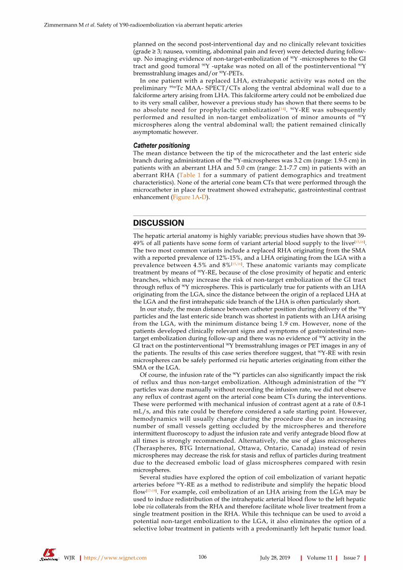
Catheter positioningThe mean distance between the tip of the microcatheter and the last enteric sidebranch during administration of the 90Y-microspheres was 3.2 cm (range: 1.9-5 cm) inpatients with an aberrant LHA and 5.0 cm (range: 2.1-7.7 cm) in patients with anaberrant RHA (Table 1 for a summary of patient demographics and treatmentcharacteristics). None of the arterial cone beam CTs that were performed through themicrocatheter in place for treatment showed extrahepatic, gastrointestinal contrastenhancement (Figure 1A-D).
DISCUSSIONThe hepatic arterial anatomy is highly variable; previous studies have shown that 39-49% of all patients have some form of variant arterial blood supply to the liver[15,16].The two most common variants include a replaced RHA originating from the SMAwith a reported prevalence of 12%-15%, and a LHA originating from the LGA with aprevalence between 4.5% and 8%[15,16]. These anatomic variants may complicatetreatment by means of 90Y-RE, because of the close proximity of hepatic and entericbranches, which may increase the risk of non-target embolization of the GI tractthrough reflux of 90Y microspheres. This is particularly true for patients with an LHAoriginating from the LGA, since the distance between the origin of a replaced LHA atthe LGA and the first intrahepatic side branch of the LHA is often particularly short.
In our study, the mean distance between catheter position during delivery of the 90Yparticles and the last enteric side branch was shortest in patients with an LHA arisingfrom the LGA, with the minimum distance being 1.9 cm. However, none of thepatients developed clinically relevant signs and symptoms of gastrointestinal non-target embolization during follow-up and there was no evidence of 90Y activity in theGI tract on the postinterventional 90Y bremsstrahlung images or PET images in any ofthe patients. The results of this case series therefore suggest, that 90Y-RE with resinmicrospheres can be safely performed via hepatic arteries originating from either theSMA or the LGA.
Of course, the infusion rate of the 90Y particles can also significantly impact the riskof reflux and thus non-target embolization. Although administration of the 90Yparticles was done manually without recording the infusion rate, we did not observeany reflux of contrast agent on the arterial cone beam CTs during the interventions.These were performed with mechanical infusion of contrast agent at a rate of 0.8-1mL/s, and this rate could be therefore considered a safe starting point. However,hemodynamics will usually change during the procedure due to an increasingnumber of small vessels getting occluded by the microspheres and thereforeintermittent fluoroscopy to adjust the infusion rate and verify antegrade blood flow atall times is strongly recommended. Alternatively, the use of glass microspheres(Theraspheres, BTG International, Ottawa, Ontario, Canada) instead of resinmicrospheres may decrease the risk for stasis and reflux of particles during treatmentdue to the decreased embolic load of glass microspheres compared with resinmicrospheres.
Several studies have explored the option of coil embolization of variant hepaticarteries before 90Y-RE as a method to redistribute and simplify the hepatic bloodflow[17-19]. For example, coil embolization of an LHA arising from the LGA may beused to induce redistribution of the intrahepatic arterial blood flow to the left hepaticlobe via collaterals from the RHA and therefore facilitate whole liver treatment from asingle treatment position in the RHA. While this technique can be used to avoid apotential non-target embolization to the LGA, it also eliminates the option of aselective lobar treatment in patients with a predominantly left hepatic tumor load.
WJR https://www.wjgnet.com July 28, 2019 Volume 11 Issue 7
Zimmermann M et al. Safety of Y90-radioembolization via aberrant hepatic arteries
106
Figure 1
Figure 1 Sample case. 52-year-old patient with an aberrant left hepatic artery originating from the left gastric artery and multifocal colorectal liver metastases in bothhepatic lobes. A: Preinterventional computed tomography (CT) angiogram (coronal maximum intensity projection) displaying the distance between the most distalhepatoenteric side branch (white arrow) and the first intrahepatic branch of the aberrant left hepatic artery (LHA) (black arrow); B: Vascular anatomy on the preliminarymapping angiogram. (white arrow: most distal hepatoenteric side branch; black arrow: first intrahepatic branch of the aberrant LHA); C: Catheter position during testinjection of technetium 99mTc macro aggregated albumin (99mTc-MAA) (and subsequently also during delivery of the 90Y microspheres); D: Post- 99mTc-MAASPECT/CT showing good tumoral 99mTc-MAA uptake and no extrahepatic activity.
Additionally, due to the irreversibility of the coil embolization, it may limit futureselective transarterial treatment options as well as surgical options, should the patientrespond extremely well to the treatment and become a surgical candidate.
The main limitations of this study include its retrospective study design and thesmall patient cohort. As mentioned before, the individual hepatic arterial anatomy ishighly variable and so are the number of hepatoenteric vessels and the distancebetween hepatic and enteric branches, which significantly impacts the risk of non-target embolization to the GI tract. Therefore, the results of this study may not beapplicable to all patients and careful evaluation of the individual arterial anatomybefore and during 90Y-RE is still necessary in all patients. Lastly, gastrointestinalcomplications after 90Y-RE are occasionally not diagnosed until several months aftertreatment[20]. However, this appears to be mostly attributable to misrecognition of therather unspecific abdominal symptoms, something that appears avoidable whenfollow-up is performed by specialists who are familiar with these potentialpostinterventional complications.
In conclusion, 90Y-RE with resin microspheres via an RHA originating from theSMA and/or a LHA replaced to the LGA appears to be feasible and safe. We did notobserve any evidence of non-target embolization in 24 patients with placement of thetip of the microcatheter at least 1.9 cm distal of the last enteric side branch and slowmanual infusion of the 90Y-particles.
ARTICLE HIGHLIGHTSResearch BackgroundRadioembolization with Yttrium-90 (90Y) microspheres is commonly used for treatment ofprimary or secondary liver tumors. It is generally a well-tolerated treatment with few sideeffects, however non-target embolization of 90Y microspheres to the gastrointestinal tract is asevere potential complication. The risk for non-target embolization is very low in patients with anormal hepatic arterial anatomy. However, around 45% of patients have some form of varianthepatic arterial anatomy and patients with aberrant hepatic arteries might have a higher risk forreflux and non-target embolization of 90Y microspheres due to the close proximity betweenhepatic and enteric vessel branches.
WJR https://www.wjgnet.com July 28, 2019 Volume 11 Issue 7
Zimmermann M et al. Safety of Y90-radioembolization via aberrant hepatic arteries
107

Research motivationSo far, no study has specifically evaluated the safety of 90Y-Radioembolization in patients with avariant hepatic arterial anatomy. Therefore, this study aimed to evaluate whether there is anincreased risk for non-target embolization during 90Y Radioembolization in this specific patientpopulation.
Research objectivesTo evaluate the safety of 90Y Radioembolization with resin microspheres in patients with one ofthe two most common hepatic arterial variants: A right hepatic artery (RHA) originating fromthe superior mesenteric artery (SMA) or a left hepatic artery (LHA) originating from the leftgastric artery (LGA).
Research methodsFor this study, electronic medical records and imaging studies of 24 patients who had beentreated with Radioembolization via an aberrant hepatic artery were retrospectively reviewedregarding clinical and imaging evidence of non-target embolization of 90Y-resin microspheres tothe GI tract. 11 patients who underwent 90Y Radioembolization via an LHA originating from theLGA and 13 patients who underwent 90Y Radioembolization via an RHA originating from theSMA were included. Positioning of the tip of the microcatheter in relationship to the lasthepatoenteric side branch was retrospectively analyzed using angiographic images, cone-beamCT and pre-interventional CT-angiograms.
Research resultsNone of the 24 patients developed clinical symptoms indicating a potential non-targetembolization to the GI tract within the first month after 90Y-RE and there was no imagingevidence of non-target embolization on the postinterventional 90Y-bremsstrahlung imagesand/or 90Y-PETs in any of the patients. The distance between the tip of the microcatheter and thelast enteric side branch was substantially shorter in patients with an aberrant LHA originatingfrom a LGA (mean distance of 3.2 cm (range: 1.9-5 cm) than in those patients with an aberrantRHA originating from the SMA (mean distance of 5.2 cm (range: 2.9-7.7 cm). However even aminimum distance of 1.9 cm was sufficient to avoid reflux and non-target embolization of 90Ymicrospheres.
Research conclusionsThis study suggests that 90Y Radioembolization may be safely performed in patients withaberrant hepatic arteries. A minimum distance of 1.9 cm between the tip of the microcatheter andthe last enteric side branch in combination with slow, manual infusion of the 90Y microsphereswas sufficient to avoid reflux of microspheres and non-target embolization in this study.
Research perspectivesAlthough this study provides clinical evidence that patients with aberrant hepatic arteries cangenerally be safely treated with 90Y Radioembolization, further studies with standardizedinfusion rates and catheter positions would be desirable to systematically determine exact cut-offvalues at which reflux and non-target embolization of 90Y microspheres occurs.
REFERENCES1 Coldwell DM, Kennedy AS, Nutting CW. Use of yttrium-90 microspheres in the treatment of unresectable
hepatic metastases from breast cancer. Int J Radiat Oncol Biol Phys 2007; 69: 800-804 [PMID: 17524567DOI: 10.1016/j.ijrobp.2007.03.056]
2 D'Avola D, Lñarrairaegui M, Bilbao JI, Martinez-Cuesta A, Alegre F, Herrero JI, Quiroga J, Prieto J,Sangro B. A retrospective comparative analysis of the effect of Y90-radioembolization on the survival ofpatients with unresectable hepatocellular carcinoma. Hepatogastroenterology 2009; 56: 1683-1688[PMID: 20214218]
3 Hoffmann RT, Paprottka PM, Schön A, Bamberg F, Haug A, Dürr EM, Rauch B, Trumm CT, Jakobs TF,Helmberger TK, Reiser MF, Kolligs FT. Transarterial hepatic yttrium-90 radioembolization in patientswith unresectable intrahepatic cholangiocarcinoma: factors associated with prolonged survival. CardiovascIntervent Radiol 2012; 35: 105-116 [PMID: 21431970 DOI: 10.1007/s00270-011-0142-x]
4 Kennedy AS, Coldwell D, Nutting C, Murthy R, Wertman DE, Loehr SP, Overton C, Meranze S,Niedzwiecki J, Sailer S. Resin 90Y-microsphere brachytherapy for unresectable colorectal livermetastases: modern USA experience. Int J Radiat Oncol Biol Phys 2006; 65: 412-425 [PMID: 16690429DOI: 10.1016/j.ijrobp.2005.12.051]
5 Kennedy AS, Dezarn WA, McNeillie P, Coldwell D, Nutting C, Carter D, Murthy R, Rose S, Warner RR,Liu D, Palmedo H, Overton C, Jones B, Salem R. Radioembolization for unresectable neuroendocrinehepatic metastases using resin 90Y-microspheres: early results in 148 patients. Am J Clin Oncol 2008; 31:271-279 [PMID: 18525307 DOI: 10.1097/COC.0b013e31815e4557]
6 Seidensticker R, Denecke T, Kraus P, Seidensticker M, Mohnike K, Fahlke J, Kettner E, Hildebrandt B,Dudeck O, Pech M, Amthauer H, Ricke J. Matched-pair comparison of radioembolization plus bestsupportive care versus best supportive care alone for chemotherapy refractory liver-dominant colorectalmetastases. Cardiovasc Intervent Radiol 2012; 35: 1066-1073 [PMID: 21800231 DOI:10.1007/s00270-011-0234-7]
7 Salem R, Gordon AC, Mouli S, Hickey R, Kallini J, Gabr A, Mulcahy MF, Baker T, Abecassis M, MillerFH, Yaghmai V, Sato K, Desai K, Thornburg B, Benson AB, Rademaker A, Ganger D, Kulik L,Lewandowski RJ. Y90 Radioembolization Significantly Prolongs Time to Progression Compared WithChemoembolization in Patients With Hepatocellular Carcinoma. Gastroenterology 2016; 151: 1155-
WJR https://www.wjgnet.com July 28, 2019 Volume 11 Issue 7
Zimmermann M et al. Safety of Y90-radioembolization via aberrant hepatic arteries
108
1163.e2 [PMID: 27575820 DOI: 10.1053/j.gastro.2016.08.029]8 Salem R, Lewandowski RJ, Kulik L, Wang E, Riaz A, Ryu RK, Sato KT, Gupta R, Nikolaidis P, Miller
FH, Yaghmai V, Ibrahim SM, Senthilnathan S, Baker T, Gates VL, Atassi B, Newman S, Memon K, ChenR, Vogelzang RL, Nemcek AA, Resnick SA, Chrisman HB, Carr J, Omary RA, Abecassis M, Benson AB,Mulcahy MF. Radioembolization results in longer time-to-progression and reduced toxicity compared withchemoembolization in patients with hepatocellular carcinoma. Gastroenterology 2011; 140: 497-507.e2[PMID: 21044630 DOI: 10.1053/j.gastro.2010.10.049]
9 Salem R, Lewandowski RJ, Mulcahy MF, Riaz A, Ryu RK, Ibrahim S, Atassi B, Baker T, Gates V, MillerFH, Sato KT, Wang E, Gupta R, Benson AB, Newman SB, Omary RA, Abecassis M, Kulik L.Radioembolization for hepatocellular carcinoma using Yttrium-90 microspheres: a comprehensive reportof long-term outcomes. Gastroenterology 2010; 138: 52-64 [PMID: 19766639 DOI:10.1053/j.gastro.2009.09.006]
10 Sangro B, Carpanese L, Cianni R, Golfieri R, Gasparini D, Ezziddin S, Paprottka PM, Fiore F, VanBuskirk M, Bilbao JI, Ettorre GM, Salvatori R, Giampalma E, Geatti O, Wilhelm K, Hoffmann RT, Izzo F,Iñarrairaegui M, Maini CL, Urigo C, Cappelli A, Vit A, Ahmadzadehfar H, Jakobs TF, Lastoria S;European Network on Radioembolization with Yttrium-90 Resin Microspheres (ENRY). Survival afteryttrium-90 resin microsphere radioembolization of hepatocellular carcinoma across Barcelona clinic livercancer stages: a European evaluation. Hepatology 2011; 54: 868-878 [PMID: 21618574 DOI:10.1002/hep.24451]
11 Yip D, Allen R, Ashton C, Jain S. Radiation-induced ulceration of the stomach secondary to hepaticembolization with radioactive yttrium microspheres in the treatment of metastatic colon cancer. JGastroenterol Hepatol 2004; 19: 347-349 [PMID: 14748889 DOI: 10.1111/j.1440-1746.2003.03322.x]
12 Lewandowski RJ, Sato KT, Atassi B, Ryu RK, Nemcek AA, Kulik L, Geschwind JF, Murthy R, RillingW, Liu D, Bester L, Bilbao JI, Kennedy AS, Omary RA, Salem R. Radioembolization with 90Ymicrospheres: angiographic and technical considerations. Cardiovasc Intervent Radiol 2007; 30: 571-592[PMID: 17516113 DOI: 10.1007/s00270-007-9064-z]
13 Paprottka PM, Jakobs TF, Reiser MF, Hoffmann RT. Practical vascular anatomy in the preparation ofradioembolization. Cardiovasc Intervent Radiol 2012; 35: 454-462 [PMID: 21567273 DOI:10.1007/s00270-011-0169-z]
14 Ahmadzadehfar H, Möhlenbruch M, Sabet A, Meyer C, Muckle M, Haslerud T, Wilhelm K, Schild HH,Biersack HJ, Ezziddin S. Is prophylactic embolization of the hepatic falciform artery needed beforeradioembolization in patients with 99mTc-MAA accumulation in the anterior abdominal wall? Eur J NuclMed Mol Imaging 2011; 38: 1477-1484 [PMID: 21494857 DOI: 10.1007/s00259-011-1807-z]
15 Covey AM, Brody LA, Maluccio MA, Getrajdman GI, Brown KT. Variant hepatic arterial anatomyrevisited: digital subtraction angiography performed in 600 patients. Radiology 2002; 224: 542-547[PMID: 12147854 DOI: 10.1148/radiol.2242011283]
16 Winston CB, Lee NA, Jarnagin WR, Teitcher J, DeMatteo RP, Fong Y, Blumgart LH. CT angiographyfor delineation of celiac and superior mesenteric artery variants in patients undergoing hepatobiliary andpancreatic surgery. AJR Am J Roentgenol 2007; 189: W13-W19 [PMID: 17579128 DOI:10.2214/AJR.04.1374]
17 Abdelmaksoud MH, Louie JD, Kothary N, Hwang GL, Kuo WT, Hofmann LV, Hovsepian DM, Sze DY.Consolidation of hepatic arterial inflow by embolization of variant hepatic arteries in preparation foryttrium-90 radioembolization. J Vasc Interv Radiol 2011; 22: 1364-1371.e1 [PMID: 21961981 DOI:10.1016/j.jvir.2011.06.014]
18 Bilbao JI, Garrastachu P, Herráiz MJ, Rodríguez M, Iñarrairaegui M, Rodríguez J, Hernández C, de laCuesta AM, Arbizu J, Sangro B. Safety and efficacy assessment of flow redistribution by occlusion ofintrahepatic vessels prior to radioembolization in the treatment of liver tumors. Cardiovasc InterventRadiol 2010; 33: 523-531 [PMID: 19841973 DOI: 10.1007/s00270-009-9717-1]
19 Karunanithy N, Gordon F, Hodolic M, Al-Nahhas A, Wasan HS, Habib N, Tait NP. Embolization ofhepatic arterial branches to simplify hepatic blood flow before yttrium 90 radioembolization: a usefultechnique in the presence of challenging anatomy. Cardiovasc Intervent Radiol 2011; 34: 287-294 [PMID:20700593 DOI: 10.1007/s00270-010-9951-6]
20 Voruganti IS, Godwin JL, Adrain A, Feller E. A Woman with Black Beads in Her Stomach: SevereGastric Ulceration Caused by Yttrium-90 Radioembolization. Case Rep Med 2018; 2018: 1413724 [PMID:29849654 DOI: 10.1155/2018/1413724]
WJR https://www.wjgnet.com July 28, 2019 Volume 11 Issue 7
Zimmermann M et al. Safety of Y90-radioembolization via aberrant hepatic arteries
109

Published By Baishideng Publishing Group Inc
7041 Koll Center Parkway, Suite 160, Pleasanton, CA 94566, USA
Telephone: +1-925-2238242
Fax: +1-925-2238243
E-mail: [email protected]
Help Desk: https://www.f6publishing.com/helpdesk
https://www.wjgnet.com
© 2019 Baishideng Publishing Group Inc. All rights reserved.