workshop manual - svcet manual department of ... carpentry 1. half lap joint 2. dovetail joint ......
TRANSCRIPT
WORKSHOP MANUAL
DEPARTMENT OF MECHANICAL ENGINEERING
SRI VENKATESWARA COLLEGE OF ENGINEERING & TECHNOLOGY
(AUTONOMOUS) Accredited by NBA, New Delhi & An ISO 9001:2000 Certified Institution
Approved by AICTE, New Delhi, Affiliated to JNTU, Anantapur
RVS Nagar, Tirupathi Road, Chittoor - 517127. (A.P)
www.svcetedu.org.

WORKSHOP MANUAL
DEPARTMENT OF MECHANICAL ENGINEERING
Subject code : 14AME03
Name of subject : Engineering Work Shop
Name : ………………………………..
Reg no : ………………………………..
Branch : ………………………………..
Year& Semester : ………………………………..

I B.TECH ALL BRANCHES
LIST OF EXPERIMENTS
CARPENTRY
1. HALF LAP JOINT
2. DOVETAIL JOINT
FITTING
3. T-FITTING
4. V-FITTING
TIN-SMITHY
5. TRAY
6. cylinder
HOUSE WIRING
7. WIRING FOR TWO LAMPS (BULBS) WITH INDEPENDENT SWITCH CONTROLS WITH OR
WITHOUT LOOPING
8. WIRING FOR STAIR CASE LAMP
FOUNDRY
9. SINGLE PIECE PATTERN (FRUSTRUM)
10. SPLIT PIECE PATTERN(DUM-BELL)
WELDING
11. LAP JOINT
12. V-BUTT WELDING
DEMO
13. PLUMBING
14. MACHINE SHOP
15. METAL CUTTING

SRI VENKATESWARA COLLEGE OF ENGINEERING & TECHNOLOGY
(AUTONOMOUS)
I B. Tech- II Semester L T P C
0 0 3 2
(14AME03) ENGINEERING WORKSHOP Lesson plan for the academic year 2014-2015
(Common to CE, ME Branches)
Objectives:
1. To understand the basic work shop tools and operations such as carpentry, fitting & sheet metal trades.
2. To understand the basic work tools of house wiring & house wiring connections etc.
3. To understand the basic joints and manufacturing processes such as foundry and welding.
Outcomes:
After completion of the study of this lab a student will be able to:
1. Distinguish between tools of various trades such as carpentry, fitting, sheet metal, welding, foundry &
house wiring.
2. Explain the tools & connections pertaining to house wiring, stair case wiring etc.
3. To describe the use of carpentry & fitting joints such as lap, dovetail, mortise, tenon joint, various sheet
metal models & manufacturing processes.
Reference Books:
1. Work shop Manual / P.Kannaiah/ K.L.Narayana/ SciTech Publishers. 2. Engineering Practices Lab Manual, Jeyapoovan, Saravana Pandian, 4/e Vikas 3. Dictionary of Mechanical Engineering, GHF Nayler, Jaico Publishing House.
SL. NO TRADES FOR EXERCISES: NO.OF. HRS. REQUIRED
CUMULATIVE HRS
A Carpentry shop
1. Making T lap joint 3 3
2. Making Dovetail lap Joint 3 6
B Fitting shop
3. Making square joint 3 9
4. Making V joint 3 12
C Sheet metal shop
5. Making Tray 3 15
6. Making cylinder 3 18
D House-wiring
7. wiring for two lamps (bulbs) with independent switch
controls with or without looping
3 21
8. wiring for stair case lamp 3 24
E Foundry
9. Preparation of moulds for a single Piece pattern 3 27
10. Preparation of moulds for Two Piece pattern 3 30
F Welding
11. Preparation of single V butt joint 3 33
12. Preparation of lap joint 36
G TRADES FOR DEMONSTRATION
13 Plumbing , Machine Shop, Metal Cutting 6 42
Lab incharge H.O.D

CARPENTARY
INTRODUCTION: Wood work or carpentry deals with making joints for a variety of applications like door frames, cabinet making furniture, packing etc., Timber:- Timber is a name obtained from well grown plants or trees. The timber must cut in such a way that the grains run parallel to the length. The common defects in timber are knots,
wet rot, dry rot etc., Market sizes of timber:- Timber is sold in market in various standard shapes and sizes. They are:- Log:- The trunk of a tree, which is free from branches. Balk:- The log sawn to have roughly square cross section. Post:- A timber piece, round or square in cross section with more than 275 mm in width, 50 to 150 mm in thickness and 2.5 to 6.5 mts length. Board:- A sawn timber piece, below 175 mm in width and 30 mm to 50 mm in thickness. Reapers:- Sawn timber pieces of assorted and nonstandard sizes, which don’t conform to the above
shapes.
WORK HOLDING TOOLS:
Carpentry vice:- It is a work holding device. When handle vice is turned in a clockwise direction, the
sliding jar forces the work against the fixed sawn. The greater the force applied to the handle, the tighter to the work held. Bar clamp:- It is a rectangular (or) square block with V-groove on one or both sides opposite to each other. It holds cylindrical work pieces. C-Clamp:- This is used to hold work against an angle plate or V-block.
MARKING AND MEASURING TOOLS:
Try square:- It is used for marking and testing the square ness of planed surfaces. It consists of a steel blade, fitted in a cast iron stock. It is also used for flatness. The size of a try square usedfor varies from 150 mm to 300 mm, according to the length of the blade. It is less accurate when compared to the try square used in fitting shop.

Fig : 1 steel rule fig: 2 marking Gauge
Fig: 3 steel tape fig: 4 Try square
Fig: 5 corpenter vice Fig: 6 Bar clamp
Fig: 7 metal jack plane Fig: 8 compass and divider

Marking gauge:-
It is a tool used to mark lines parallel to the edges of wooden pieces. It consists of a
square wooden stem with a riding wooden stock on it. A marking pin, made of steel is
fitted on the stem. A mortise gauge consists of two pins. In these it is possible to adjust
the distance between the pins, to draw two parallel lines on the stock.
Compass and dividers:- This is used for marking circles, arcs, laying out perpendicular lines on the planed surface of the wood.
CUTTING TOOLS:
Hack saw:- It is used to cross cut the grains of the stock. The teeth are so set that the saw kerfs will be wider than the blade thickness. Hard blades are used to cut hard metals. Flexible blades
are having the teeth of hardened and rest of the blade is soft and flexible.
Chisels:- These are used for removing surplus wood. Chisels are annealed, hardened and tempered to produce a tough shank and a hard cutting edge.
Rip saw:- It is used for cutting the stock along the grains. The cutting edge of this saw makes a sleeper
angle about 60o whereas that saw makes an angle of 45o with the surface of the stock.
Tenon saw:- It is used for cutting tenons and in fine cabinet works. The blade of this saw is very thin and so it is used stiffed with back strip. Hence, this is sometimes called back saw. The
teeth shapes similar to cross cut saw.
DRILLING AND BORING TOOLS:
Auger bit:- It is the most common tool used for boring holes with hard pressure. Gimlet:- This is a hand tool used for boring holes with hand pressure.
Hand drill:- Carpenters brace is used to make relatively large size holes, whereas hand drill is used for drilling small holes. A straight shank drill is used with these tools. It is small light in
weight and may be conveniently used than the brace. The drill is clamped in the chuck.

Fig: 9 cross cut saw Fig: 10 Tenon saw Fig: 11 compass saw
Fig: 12 Chisels Fig: 13 Carpenter’s brace Fig: 14 Auger bit
Fig: 15 Gimlet Fig: 16 wood rasp file Fig:17 Mallet
Fig: 18 Hand drill Fig: 19 Trammel Fig: 20 Claw hammer
MISCELLANEOUS TOOLS:
Ball peen hammer:- It has a flat face, which is used for general work and a ball end is used for riveting.
Mallet:- It is used to drive the chisel, when considerable force is to be applied, steel hammer should not be used for these purpose, as it may damage the chisel handle. Further, for
better to apply a series of light taps with the mallet rather than a heavy single blow.
Claw hammer:- It is a striking flat at one end and the claw at the others. The face issued to drive nails into wood and for other striking purpose and the claw for extracting nails out of wood.
Pinches:- It is made of steel with a hinged and is used for pulling out small nails from wood.
Wood rasp file:- It is a finishing tool used to make the wood smooth, remove sharp edge finishing fillets and other interior surfaces. Sharp cutting teeth are provided on its surface for the purpose.
This file is exclusively used in wood work.
CARPENTRY SECTION
T-LAP JOINT
EXPERIMENT NO: 1 DATE:
Aim: - To make a T- lap joint
Tools required: - 1. Carpenter’s vice
2. Steel Rule 3. Try square 4. Jack plane 5. Scriber 6. Cross cut saw 7. Marking gauge 8. Firmer chisel 9. Mallet 10. Wood rasp file and smooth file
Material required: - Wooden pieces of size 50 x 35 x 250 mm–2 Nos.
Sequence of operations: -
1. Measuring and Marking 2. Planning 3. Check for squareness 4. Removal of extra material 5. Sawing 6. Chiseling 7. Finishing


Procedure: -
1. The given reaper is checked for dimensions. 2. They are planed with jack plane and checked for straightness. 3. The two surfaces are checked for squareness with a try square. 4. Marking gauge is set and lines are marked at 30 and 45 mm to mark the
thickness and width of the model respectively. 5. The excess material is first chiseled with firmer and then planned to correct
size. 6. The mating dimensions of the parts X and Y are then marked using steel rule
and marking gauge. 7. Using the crosscut saw, the portions to be removed are cut in both the pieces,
followed by chiseling. 8. The ends of both the parts are chiseled to the exact lengths. 9. The fine finishing is given to the parts, if required so that, proper fitting is
obtained. 10. The parts are fitted to obtain a slightly tight joint.
Safety precautions: -
1. Loose cloths are to be avoided. 2. Tools to be placed at their proper placed. 3. Hands should not be placed in front of sharp edged tools. 4. Use only sharp tools. 5. Care should be taken, when thumb is used as a guide in cross cutting and
ripping. 6. Handle while chiseling, sawing and planning with care. 7.
Result: - T- lap joint is made as per the required dimensions.

CARPENTRY SECTION
DOVETAIL LAP JOINT
EXPERIMENT NO: DATE:
Aim: - To make a Dovetail lap joint from the given reaper of size 50 x35 x250 mm. Tools required: -
1. Carpenter’s vice
2. Steel Rule 3. Try square 4. Jack plane 5. Scriber 6. Cross cut saw 7. Marking gauge 8. Firmer chisel 9. Mortise chisel 10. Mallet 11. Wood rasp file and smooth file
Material required: - Wooden pieces of size 50 x 35 x 250 mm–2 Nos. Sequence of operations: -
1. Measuring and Marking 2. Planning 3. Check for square ness 4. Removal of extra material 5. Sawing 6. Chiseling 7. Finishing


Procedure: -
1. The given reaper is checked for dimensions. 2. They are planed with jack plane and checked for straightness. 3. The two surfaces are checked for square ness with a try square. 4. Marking gauge is set and lines are marked at 30 and 45 mm to mark the
thickness and width of the model respectively. 5. The excess material is first chiseled with firmer chisel and then planned to
correct size. 6. The mating dimensions of the parts X and Y are then marked using steel rule
and marking gauge. 7. Using the crosscut saw, the portions to be removed are cut in both the pieces,
followed by chiseling. 8. The ends of both the parts are chiseled to the exact lengths. 9. The fine finishing is given to the parts, if required so that, proper fitting is
obtained. 10. The parts are fitted to obtain a slightly tight joint.
Safety precautions: -
1. Loose cloths are to be avoided. 2. Tools to be placed at their proper placed. 3. Hands should not be placed in front of sharp edged tools. 4. Use only sharp tools. 5. Care should be taken, when thumb is used as a guide in cross cutting and
ripping. 6. Handle while chiseling, sawing and planning with care.
Result: - Dovetail lap joint is made as per the required dimensions.

FITTING
INTRODUCTION: Machine tools are capable of producing work at a faster rate, but there are occasions
when components are processed at a bench. Sometimes it becomes necessary to replace
or repair a component that must fit accurately with one another or reassemble. This
involves a certain amount of hand fitting. The assembly machine tools, jigs, gauges etc.,
involves certain amount of bench work.
FITTING TOOLS:
Holding tools:-
Bench vice
V-block with clamp
C-clamp Bench vice:- It is a work holding device, when vice handle is turned in a clockwise direction the sliding jaw forces the work against the fixed jaw, the greater the force applied to the
handle, the tighter is the work held. V-block with clamp:- It is a rectangular (or) square block with v-groove on one or both sides, opposite to each other. It holds cylindrical work pieces. C-clamp:-
This is used to hold work against an angle plate or v-block. MARKING AND MEASURING TOOLS:
1. Surface plate
2. Try square 3. Angle plate
4. Scriber 5. Universal scribing block 6. Odd leg caliper 7. Divider 8. Calipers 9. Dot punch 10. Vernier caliper
Surface plate:- It is used for testing flatness of work piece, for marking out small works.

Fig: 1 Bench wise Fig: 2 V- Block
Fig: 3 C – Clamp Fig: 4 Surface plate
Fig: 5 Angle plate Fig: 6 Dot punch
Fig: 6 try square Fig: 7 scriber

Combination cutting pliers: -
This is made of tool steel and is used for cutting as well as for ripping work.
Taps and die holders: - Tap and wrenches are used for cutting internal threads in a drilled hole. Dies and die holders:- They are used for making external threads. Dies are made either solid (or) split type.
TYPES OF FILES:
Hand file:-
It is a rectangular in section tapered in thickness but parallel in width.
Flat file:-
Rectangular in section and tapered for 1/3rd
length in width and thickness.
Square file:-
Square in section and tapered for 1/3rd
length on all sides.
Half round file:-
It has one flat face, connecting by a curved (surface) face & tapered for 1/3rd
length.
Round file:-
Circular in cross section and tapered for 1/3rd
length, it has double cut teeth.
MISCELLANEOUS TOOLS:
Ball peen hammer:- It has a flat face, which is used for general work and a ball end is used for riveting.
Screw driver:- It is designed to turn the screws. The blade is made of steel and is available in different lengths and diameters.
Spanners:- It is a tool for turning nuts and bolts. It is usually made of forged steel.
FITTING OPERATIONS:
Chipping:- Removing metal with a chisel is called chipping and is normally used where machining is not possible.
Fitting:- 1. Pinning of files:-
Soft metals cause this; the pins are removed with a file card. 2. Checking flatness and square ness:-
To check flatness across thickness of plate.
MARKING AND MEASURING: Measurements are taken either from a center line, for visibility of the non-ferrous metals and oxide coated steels are used.

Fig: 8 odd leg clamp and divider
Fig: 9 calipers Fig: 10 Vernier caliper
Fig: 11 Parts of hand file

Fig: 12 Types of files Fig: 13 ball peen hammer

FITTING SECTION
SQUARE (T) - FITTING
EXPERIMENT NO: DATE:
Aim: - To make M.S Plate into required model by T-fitting.
To make a T-fitting from the given two M.S pieces. Tools required: -
1. Bench vice 2. Steel rule 3. Try square 4. Ball peen hammer 5. Scriber 6. Hack saw with blade 7. Dot punch and Centre punch 8. Surface plate 9. Venire height gauge 10. Rough and smooth flat files 11. Flat chisel and triangular file
Material required: - Mild steel (M.S) plate of size 48 x 34–2 Nos. Sequence of Operations: -
1. Filing 2. Checking flatness and square ness 3. Marking and measuring 4. Punching 5. Sawing 6. Chipping 7. Finishing

Fig: SQUARE (T) - FITTING

Procedure: -
1. The burrs in the pieces are removed and the dimensions are checked with a
steel rule. 2. The pieces are clamped one after the other and the outer mating edges are filed
by using rough and smooth files. 3. The flatness, straightness and square ness i.e. right angle between adjacent
sides are checked with help of Try-square. 4. Chalk is then applied on the surfaces of the two pieces. 5. The given dimensions of the T-fitting are marked with help of vernier height
gauge carefully. 6. Using the dot punch, dots are punched along the above scribed lines. 7. Using the hack saw, the unwanted portions are removed. 8. Using the flat chisel, the unwanted material in the piece Y is removed. 9. The cut edges are filed by the half round file. 10. The corners of the stepped surfaces are filed by using a square or triangular file
to get the sharp corners. 11. The pieces (X and Y) are fitted together and the mating is checked for the
correctness of the fit.
Safety precautions: -
1. Care is taken to see that the marking dots are not crossed, which is indicated by
the half of the punch dots left on the pieces. 2. Apply pressure in forward direction during hack sawing. 3. Don’t rub steel rule on the job.
4. Fix blade in hack saw frame with correct tension. 5. During hack sawing the coolant like water or lubricating oil is to be used. 6. Use precision instruments like vernier calipers and vernier height gauge
carefully. 7. Files are to be cleaned properly after using.
Result: - T-fit is made as per the required dimensions.

FITTING SECTION
V- FITTING
EXPERIMENT NO: DATE:
Aim: - To make M.S Plate into required model by V- fitting. To make a V- fitting from the given two M.S pieces.
Tools required: -
1. Bench vice 2. Steel rule 3. Try square 4. Ball peen hammer 5. Scriber 6. Hack saw with blade 7. Dot punch and Centre punch 8. Surface plate 9. Vernier height gauge 10. Rough and smooth flat files 11. Flat chisel and triangular file
Material required: - Mild steel (M.S) plate of size 48 x 34–2 Nos.
Sequence of Operations: -
1. Filing 2. Checking flatness and square ness 3. Marking and measuring 4. Punching 5. Sawing 6. Chipping 7. Finishing


Procedure: -
1. The burrs in the pieces are removed and the dimensions are checked with a
steel rule. 2. The pieces are clamped one after the other and the outer mating edges are filed
by using rough and smooth files.
3. The flatness, straightness and square ness i.e. right angle between adjacent
sides are checked with help of Try-square. 4. Chalk is then applied on the surfaces of the two pieces. 5. The given dimensions of the V-fitting are marked with help of vernier height
gauge carefully. 6. Using the dot punch, dots are punched along the above scribed lines. 7. Using the hack saw, the unwanted portions are removed. 8. Using the flat chisel, the unwanted material in the piece Y is removed. 9. The cut edges are filed by the half round file. 10. The corners of the stepped surfaces are filed by using a square or triangular file
to get the sharp corners. 11. The pieces (X and Y) are fitted together and the mating is checked for the
correctness of the fit. Safety precautions: -
1. Care is taken to see that the marking dots are not crossed, which is indicated by
the half of the punch dots left on the pieces. 2. Apply pressure in forward direction during hack sawing. 3. Don’t rub steel rule on the job.
4. Fix blade in hack saw frame with correct tension. 5. During hack sawing the coolant like water or lubricating oil is to be used. 6. Use precision instruments like vernier calipers and vernier height gauge
carefully. 7. Files are to be cleaned properly after using.
Result: - V- fit is made as per the required dimensions.

TIN SMITHY
INTRODUCTION: Many engineering and house hold articles such as boxes, cans, funnels, ducts etc., are
made from a flat sheet of metals. These process being known as tin smithy. For this, the
development of the article is first drawn on the sheet metal then cut and folded to form
the required shape of the article. The edge of the articles are then secured through
welding, brazing, soldering, riveting etc.,
Sheet metal materials:- A variety of metals used in a sheet metal shop such as black iron, aluminum and stainless
steel. A sheet of soft steel which is coated with molten zinc is known as galvanized iron.
The zinc coat forms a coating that resists rust, improves the appearance of the metal and
permits it to be solderised with greater care.
Hand tools:- The common hand tools used in sheet metals work are steel rule, usually of 60 cm length, Vise gauge, dot punch, scriber, trammels, ball peen hammer, and straight peen hammer,
cross peen hammer, mallets, snips and soldering iron.
Trammels:- Sheet metals layouts require marking of arcs and circles. This may be done by using the
trammels. The length of the beam decides the maximum size of the arc that can be scribed.
Wire gauge:- The thickness of the sheet metal is referred in numbers known as standard wire gauge (SWG). The gaps in the circumstance of the gauge are used to check the gauge number.
Bench shears:- Sheet metal may be cut by shearing action. In this the force is applied through a
compound lever, making it possible to cut sheet metal up to 4mm thick. The chopping
hole can shear a mild steel rod up to 10mm diameter.
Snips:- Snips are hand shears, varying in length from 200mm to 600mm. 200mm to 250mm
being the commonly used. The straight lines are curved snips or bent snips are for trimming along inside curves.
Hammers:- Ball peen hammer has a cylindrical slightly curved face and a ball head straight peen and similar to the cross peen, but it is positioned paralleled to the handle which can be used
conveniently for certain operations of folding.
Stakes:- Stakes are nothing but anvils, which are used as supporting tools and to form seam, bend, rivet sheet metal objects.

Fig: 1 Sheet metal joints
Fig: 2 Stakes

Snips:- Snips are hand shears, varying in length from 200mm to 600mm. 200mm to 250mm being the commonly used. The straight lines are curved snips or bent snips are for
trimming along inside curves.
Hammers:- Ball peen hammer has a cylindrical slightly curved face and a ball head straight peen and
similar to the cross peen, but it is positioned paralleled to the handle which can be used conveniently for certain operations of folding.
Stakes:- Stakes are nothing but anvils, which are used as supporting tools and to form seam, bend, rivet sheet metal objects.
SHEET METAL JOINTS: Various types of joints are used in sheet metal work to suit the varying requirement.
These are self-secured joints, formed by joining together two pieces of sheets metal and
using the metal itself to form the joints. These joints are to be used on sheets of less than
1.6mm thickness.
Riveting:- Rivets are used to fasten two of more sheets of metal together. It is the common practice to use the rivets of the same material as that of the sheets having fastened.
Sheet metal screws:- These are used in sheet metal work to join and install duct work for ventilation air
conditioning etc. These screws are also known as self-tapping screws since they cut their own threads.
Soldering:- Soldering is one method of joining two pieces of metal with an alloy that melts at a lower
temperature than the metals to be joined for a good job. The metals to be joined must be
free from dirt, grease and oxide. Solder is made of tin and lead in equal proportions. It
comes either in the form of wire and bar.
Soldering iron:- Soldering requires a source of heating. A common method of transmitting heat of the metal surfaces is by using a soldering iron.

TINSMITHY SECTION
TRAY
EXPERIMENT NO: DATE:
Aim: - To make a tray using the given G.I. Sheet. Tools required: -
1. Steel rule 2. Scriber 3. Straight snip 4. Bench vice 5. Stake 6. Cross peen hammer 7. Wooden mallet 8. Cutting pier
Material required: - Galvanized Iron (G.I) sheet 110 x 125 mm size. Sequence of operations: -
1. Cleaning 2. Surface leveling 3. Marking 4. Cutting 5. Folding


Procedure: -
1. Clean the given sheet with cotton waste. 2. The size of the given sheet is checked with the steel rule. 3. Flatten the surface of the given sheet with wooden mallet. 4. Check the G.I. Sheet for dimensions and remove extra material, if any. 5. Mark all the measuring lines on the given sheet with scriber. 6. Cut the given sheet with straight snips as required. 7. Fold the given sheet by using stakes and ball peen hammer to the required
shape.
Safety precautions: -
1. For marking purpose use scriber only. Do not use pencil or pen. 2. Sufficient care is to be taken while cutting and folding of G.I. sheet. 3. Remove the waste pieces immediately from the work place.
Result: - Tray is prepared as per the required dimensions.

TINSMITHY SECTION
Cylinder
EXPERIMENT NO: DATE:
Aim: - To make a Cylinder using the given G.I. Sheet. Tools required: -
1. Steel rule 2. Scriber 3. Straight snip 4. Bench vice 5. Stake 6. Cross peen hammer 7. Wooden mallet 8. Cutting pier
Material required: - Galvanized Iron (G.I) sheet 160 x 80mm size. Sequence of operations: -
1. Cleaning 2. Surface leveling 3. Marking 4. Cutting 5. Folding

Fig: cylinder

Procedure: - 8. Clean the given sheet with cotton waste. 9. The size of the given sheet is checked with the steel rule. 10. Flatten the surface of the given sheet with wooden mallet. 11. Check the G.I. Sheet for dimensions and remove extra material, if any. 12. Mark all the measuring lines on the given sheet with scriber. 13. Cut the given sheet with straight snips as required. 14. Fold the given sheet by using stakes and ball peen hammer to the required shape.
Safety precautions: - 1. For marking purpose use scriber only. Do not use pencil or pen. 2. Sufficient care is to be taken while cutting and folding of G.I. sheet. 3. Remove the waste pieces immediately from the work place.
Result: -cylinder is prepared as per the given dimensions.

HOUSE WIRING
Introduction: Power is supplied to domestic installations through a phase and a neutral, forming a single
phase. A.C 230V, 2- wire system for industrial establishments. Power is supplied through
three phase four wire system to give 440V. Fig.Shows the power tapping for domestic and
industrial purposes. The neutral is earthed at the distribution sub-station of the supply. When supplied to domestic utilizes power is fed to a kilowatt meter and then to a
distribution panel. The panel distributes power along several circuits’ breakers. The panel also serves as a main switch.
Electrical wiring is defined as a system of electrical conductors, components and
apparatus for conveying electrical power from the source to the point of use. The wiring system must be designed to provide a constant voltage to the load. Elements of house wiring:
Fuses & circuit Breakers: These are the devices to provide protection to a circuit against excess current. Open link fuses are not in safe in operations, even though they are cheaper and reliable. It consists
of a thin strip of metal (or) wire. Electric switch: This is a device that makes and breaks or changes the course of electric circuit. It consists of 2 or more contacts mounted on an insulating structure and arranged such that they may
be moved in to and out of contact with each other by a suitable operating mechanism. Plug: It is a device carrying 2 or 3 contact, designed for engagement with corresponding plugs
pins and arranged for connection to fixed wiring and arranged for attachment to
appliances such as radio, T.V, table, fan etc., Socket outlet:- It is a device carrying 2 or 3 contacts, designed for engagement with corresponding plug pins and arranged for connection to fixing wiring. Lamp holder:- These are designed to hold lamps & connect them in the circuit. Both bay one cap and screw lamp holders are available up to 200 watts lamps. Ceiling rose:- A ceiling rose consists of a circular base & cover made of Bakelite. The base has 2 or 3
terminal plates. One end of the plate is connected to supply wire connected to pendent lamp, ceiling fan, exhaust fan, etc.


Main switch:- This is a switch intended to connect or cut-off the supply of electrical to the whole of an installation. It is generally of metal clad type. The metal clad gives greater strength and safety. The main switch contains one or more fuses, single phase, and A.C. circuits. Incandescent light:- Incandescent means ‘glowing at white heat’. A lamp actually works like heating elements that it
gives off light by becoming white hot, the amount of power it consume is stamped on the bulb.
Higher the wattage, brighter the light. The bulbs have filaments made of tungsten.
Interior wiring:-Wires & wire sizes:- A wire is defined as a bare or insulated conductor consisting of one (or) several strands. An
insulating wire consists of a conductor with insulating material made of Vulcanized Indian
Rubber (VIR) (or) Poly Vinyl Chloride (PVC). The wire may consist of 1 or several twisted
strands. A multi sore conductor consists of several cores insulated from one another and enclosed
in a common seating. Wire sizes are specified by the diameter of the wire, using a standard wire
gauge (SWG), which also gives an idea of the current carrying capacity. The specification
consists of the both the number of strands and the diameter of the each wire in it

HOUSE WIRING SECTION
ONE LAMP CONTROLLED BY TWO TWO-WAY SWITCHES
(STAIR CASE CONNECTION)
EXPERIMENT NO: DATE:
Aim: - to give connections to one lamp controlled by two two-way switches. Tools required: -
1. Screw driver 2. Cutting pliers 3. Ball peen hammer 4. Insulation remover 5. Tester
Material required: -
1. Wooden wiring board 2. Silk wire 3. Electrical bulb - 1 No
4. Two -way switches - 2Nos
5. Wooden round block - 1 No
6. Batten lamp holder - 1 No 7. Wire clips 8. Nails 9. Screws

Fig:1 One lamp controlled by 2 two – way switches

Procedure: -
1. The outline of the wiring diagram is marked on the wooden wiring board. 2. Clips are nailed to the board, following the wiring diagram. 3. Wires are stretched and clamped with the clips. 4. Round blocks are screwed on to the board, as per the diagram. 5. Wires are connected to the holders and the switch, which are then screwed on
to the round blocks. 6. Bulb is fitted to the holder.
7. The wiring connections are tested, by giving power supply.
Safety precautions: -
1. Electricity has no respect for ignorance. Do not apply voltage or turn-on any device
until it has been properly checked. 2. Care should be taken from electrical shocks. 3. Don’t touch the connection points.
4. Avoid loose connection. 5. Don’t work at damped areas and with wet clothing.
6. Handle the lamp carefully.
Result: - Connections are given to one lamp controlled by two two-way switches andtested.

HOUSE WIRING SECTION
Wiring For Two Lamps (Bulbs) With Independent Switch Controls
with or Without Looping
EXPERIMENT NO: DATE:
Aim: - To give connection to two lights, controlled With Independent Switch Controls
with or Without Looping.
Tools required: -
1. Screw driver 2. Cutting pliers 3. Ball peen hammer 4. Insulation remover 5. Tester
Material required: -
1. Wooden wiring board 2. Silk wire 3. Electrical bulbs - 2 No
4. One-way switch - 1No
5. Wooden round blocks - 1 No
6. Batten lamp holders - 1 No 7. Wire clips 8. Nails 9. Screws

Fig: Two lights controlled by two independent switchs
Procedure: -
1. The outline of the wiring diagram is marked on the wooden wiring board. 2. Clips are nailed to the board, following the wiring diagram. 3. Wires are stretched and clamped with the clips. 4. Round blocks are screwed on to the board, as per the diagram. 5. Wires are connected to the holders and the switch, which are then screwed on
to the round blocks. 6. Bulb is fitted to the holder. 7. The wiring connections are tested, by giving power supply.
Safety precautions: -
1. Electricity has no respect for ignorance. Do not apply voltage or turn-on any
device until it has been properly checked. 2. Care should be taken from electrical shocks. 3. Don’t touch the connection points.
4. Avoid loose connection. 5. Don’t work at damped areas and with wet clothing. 6. Handle the lamp carefully.
Result: - Connections are given to two bulbs controlled by the two independent switches
and Tested

FOUNDRY
Introduction: - Foundry practice deals with the process of making casting in moulds, formed in
either sand or other material. This is found to be the cheapest method of metal shaping. The
process involves the operations of pattern making, sand preparation, molding, melting of metals, pouring in moulds, cooling, shake out, fettling, heat treatment, finishing, and inspection.
Mould is a cavity in a molding core, formed by a pattern. It is similar in shape and size that of the actual casting plus some allowance for shrinkage, machining etc., molding is the process of making molds. Moulds are classified as: -
Temporary moulds
Permanent moulds
Temporary mould are made of sand and other binding materials and may be produced either
through hand molding (or) machine molding.
Permanent moulds are made of ferrous materials and alloys i.e., cast iron, steel etc., Molding Sand: -
Sand is the principle material used in foundry. The principle ingredients of molding sands are
1) Silicon sand 2) Clay 3) Sand Clay imparts the necessary bonding strength to the molding sand, moisture when added
to correct preparation provides the bonding action to the clay sand can withstand high
temperature and doesn’t react with molten metal. Natural molding sand is either available in river beds are dug from pits. It possesses and
appreciable amount of clay and are used as received with the addition of water. Synthetic sands are prepared by adding clay. Water and other materials to silica sand so that the desirable strength and banding properties are achieved.
Most of molding is done with green sand i.e.; sand containing 6 to 8%, moisture and 10% clay content to give it sufficient bond. Green sand moulds are used for pouring the molten metal
– immediately after preparing the moulds. Green sand moulds are cheaper and take less time to prepare. These are used for small and medium size casting.
Parting sand, which is clay tree, fence grained silica sand, is used to keep the green sand from sticking to the pattern and also to prevent the cope and drug from cleaning. Core sand is
used for making cores. This is silica missed with core oil and other oddities.


Pattern; - A pattern is the replica of the desired coasting, which when packed in a suitable
materials produces a cavity called mould. This cavity when filled with molten metals,
produces their desired coasting of the solidification. Types of pattern; -
Wood are metal patterns are used in foundry practice, single piece, split loose piece and cored patterns are some of the common types.
Tools and equipment; - The tools are equipment needed for molding are; -
Molding board: - It is wooden board with smooth surfaces. It supports the flasks and the pattern,
while the mould is being made. Molding Flask: -
It is a base, made of wood or metal, open at both ends. The sand is rammed in
after placing the pattern to produce a mould it is made of 2 parts; cope is the top half of
the flask, having guides for the aligning paints to enter. Drag is the bottom half of the
flask having aligning pins. Shovel: -
It is used for mixing and tempering molding sand and for transferring the sand in to the flask. It is made of steel blade with a wooden handle. Rammer: -
It is used for pocking or ramming the sand, around the pattern one of its ends
called the peen end, is wedge shaped and is used for packing sand in spaces, pockets and
corners in the early stages of ramming. The other end called the But – end has a surface
and is used for computing the sand towards the end of molding. Strike of edge / strike of bar: -
It is a piece of metal or wood with straight edge. It is used remove the excess sand from the mould after ramming to provide a level surface. Spruce pin: -
It is tapered wooden pin used to make a hole in the cope sand through which the molten metal is poured into the mould. Riser pin: -
It is tapered wooden pin used to make a hole in the cope sand over the mould
cavity for the molten metal to rise and feed the casting to compassable the shrinkage that
take place during solidification. Trowel: -
It is used to smoothen the surface of the mould. It may also be used for
reproducing the damaged portion of the mould. A trowel is made in many different styles and sizes each one recallable for a particular hole.

FOUNDRY
ONE STEPPED PATTERN
(SINGLE PIECE PATTERN)
EXPERIMENT No: DATE:
Aim: - To prepare a sand mould cavity using One Stepped Shaft (single piece pattern). Tools required: -
1. Molding board 2. Molding flask 3. Shovel 4. Riddle 5. Rammer 6. Strike-off bar or Strike Edge 7. Sprue pin 8. Riser pin 9. Trowel 10. Spike or Draw pin 11. Slick 12. Lifters 13. Gate cutter 14. Bellows 15. Vent rod
Material required: -
1. Molding sand 2. Parting sand 3. Dum-Bell
Sequence of operation: -
1. Sand preparation 2. Sandmixing
3. Pouring
4. Finishing
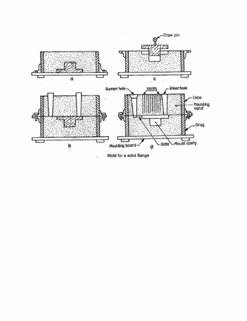

Procedure: -
1. Place the pattern on the molding board, with its flat side on the board. 2. Place the drag over the board, after giving a clay wash inside. 3. Sprinkle the pattern and molding board, with parting sand. 4. Allow loose sand, preferably through a riddle over the pattern, unit it is
covered to a depth of 2 to 3 cm. 5. Pack the molding sand around the pattern and into the corners of the flask, with
fingers. 6. Place some more sand in the flask and pack the pattern with a rammer, using
first the peen end and then butt end. 7. Strike-off the excess sand from the top surface of the drag with the strike-off bar. 8. Turn the drag upside down. 9. Blow-off the loose sand particles with the bellows and smoothen the upper
surface. 10. Place the cope on to the drag in position. Locate riser pin on the highest point
of the pattern. 11. Place the sprue pin at about 5 to 6 cm from the pattern on the other side of the
riser pin. 12. Sprinkle the upper surface with parting sand. 13. Repeat steps 3 to 7, approximately. 14. Make holes with the vent rod to about 1 cm from the pattern. 15. Remove the sprue and riser pins by carefully drawing them out. Funnel shaped
hole is made at the top of the sprue hole, called the pouring cup. 16. Lift the cope and place it aside on its edge. 17. Insert the draw pin into the pattern. Wet the edges around the pattern. Loosen
the pattern by rapping. Then draw the pattern straight up. 18. Adjust and repair the mold by adding bits of sand, if necessary. 19. Cut gate in the drag from the sprue to the mold. Blow off any loose sand
particles in the mold. 20. Close the mold by replacing the cope and placing weights on it.
Precautions:-
1. Do not get the sand too wet. Water is an enemy of molten metals. 2. Provide adequate ventilation to remove smoke and fumes. 3. Never stand near or look over the mold during the pouring because of the
molten metal might be too hot. 4. Do not shake out a casting too hastily, which may result in second and third
degree burns. Result: - A sand mold cavity is prepared by using one–Stepped Shaft.

FOUNDRY
DUM-BELL
(SPLIT PIECE PATTERN)
EXPERIMENT No: DATE:
Aim: - To prepare a sand mould cavity using Dum-Bell (split piece pattern). Tools required: -
1. Molding board 2. Molding flask 3. Shovel 4. Riddle 5. Rammer 6. Strike-off bar or Strike Edge 7. Sprue pin 8. Riser pin 9. Trowel 10. Spike or Draw pin 11. Slick 12. Lifters 13. Gate cutter 14. Bellows 15. Vent rod
Material required: -
1. Molding sand 2. Parting sand 3. Dum-Bell
Sequence of operation: -
1. Sand preparation 2. Sand mixing 3. Pouring
4. Finishing

Fig: 1 Dum – Bell pattern
Fig: 2 mould of two piece pattern

Procedure: -
1. Place the pattern on the molding board, with its flat side on the board. 2. Place the drag over the board, after giving a clay wash inside. 3. Sprinkle the pattern and molding board, with parting sand. 4. Allow loose sand, preferably through a riddle over the pattern, unit it is covered to a
depth of 2 to 3 cm. 5. Pack the molding sand around the pattern and into the corners of the flask, with
fingers. 6. Place some more sand in the flask and pack the pattern with a rammer, using first the
peen end and then butt end. 7. Strike-off the excess sand from the top surface of the drag with the strike-off bar. 8. Turn the drag upside down. 9. Blow-off the loose sand particles with the bellows and smoothen the upper surface. 10. Place the cope on to the drag in position. Locate riser pin on the highest point of the
pattern.
11. Place the sprue pin at about 5 to 6 cm from the pattern on the other side of the riser
pin. 12. Sprinkle the upper surface with parting sand. 13. Repeat steps 3 to 7, approximately. 14. Make holes with the vent rod to about 1 cm from the pattern. 15. Remove the sprue and riser pins by carefully drawing them out. Funnel shaped hole is
made at the top of the sprue hole, called the pouring cup. 16. Lift the cope and place it aside on its edge. 17. Insert the draw pin into the pattern. Wet the edges around the pattern. Loosen the
pattern by rapping. Then draw the pattern straight up. 18. Adjust and repair the mold by adding bits of sand, if necessary. 19. Cut gate in the drag from the sprue to the mold. Blow off any loose sand particles in
the mold. 20. Close the mold by replacing the cope and placing weights on it.
Precautions:-
1. Do not get the sand too wet. Water is an enemy of molten metals. 2. Provide adequate ventilation to remove smoke and fumes. 3. Never stand near or look over the mold during the pouring because of the molten
metal might be too hot. 4. Do not shake out a casting too hastily, which may result in second and third degree
burns. Result: - A sand mold cavity is prepared by using Dum-Bell.

WELDING
INTRODUCTION
Welding is the process of joining similar metals by the application of heat, with or
without application of pressure or filler metal, in such a way that the joint is equivalent in
composition andcharacteristics of the metals joined. In the beginning, welding was mainly used
for repairing all kinds ofworn or damaged parts. Now, it is extensively used in manufacturing
industry, construction industry(construction of ships, tanks, locomotives and automobiles) and
maintenance work, replacing rivetingand bolting, to a greater extent.
The various welding processes are:
1. Electric arc welding,
2. Gas welding
3. Thermal welding
4. Electrical Resistance welding and
5. Friction welding
However, only electric arc welding process is discussed in the subject point of view.
Electric arc welding
Arc welding is the welding process, in which heat is generated by an electric arc struck between
an electrode and the work piece. Electric arc is luminous electrical discharge between two
electrodes
through ionized gas.
Any arc welding method is based on an electric circuit consisting of the following parts:
a. Power supply (AC or DC);
b. Welding electrode;
c. Work piece;
d. Welding leads (electric cables) connecting the electrode and work piece to the power supply.

Fig:1 Arc welding set up
Fig :2 parts of an electrode

Electric arc between the electrode and work piece closes the electric circuit. The arc
temperature may reach 10000°F (5500°C), which is sufficient for fusion the work piece edges
and joining them. When a long joint is required the arc is moved along the joint line. The front
edge of the weld pool melts the welded surfaces when the rear edge of the weld pool solidifies
forming the joint.
Transformers, motor generators and rectifiers’ sets are used as arc welding machines.
These machines supply high electric currents at low voltage and an electrode is used to produce
the necessary arc. The electrode serves as the filler rod and the arc melts the surface so that, the
metals to be joined are actually fixed together.
Sizes of welding machines are rated according to their approximate amperage capacity at
60% duty cycle, such as 150,200,250,300,400,500 and 600 amperes. This amperage is the rated
current output at the working terminal.
Transformers
The transformers type of welding machine produces A.C current and is considered to be theleast
expensive. It takes power directly from power supply line and transforms it to the voltage
required for welding. Transformers are available in single phase and three phases in the market.
Motor generators
These are D.C generators sets, in which electric motor and alternator are mounted on the same
shaft to produce D.C power as pert the requirement for welding. These are designed to produce
D.C current in either straight or reversed polarity. The polarity selected for welding depends
upon the kind of electrode used and the material to be welded.
Rectifiers
These are essentially transformers, containing an electrical device which changes A.C into D.C
by virtue of which the operator can use both types of power (A.C or D.C, but only one at a
time).In addition to the welding machine, certain accessories are needed for carrying out the
welding work.
Welding cables
Two welding cables are required, one from machine to the electrode holder and the other,
from the machine to the ground clamp. Flexible cables are usually preferred because of the case
of usingand coiling the cables. Cables are specified by their current carrying capacity, say 300 A,
400 A, etc.

Electrodes
Filler rods are used in arc welding are called electrodes. These are made of metallic wire called
core wire, having approximately the same composition as the metal to be welded. These are
coated uniformly with a protective coating called flux. While fluxing an electrode; about 20mm
of length is left at one end for holding it with the electrode holder. It helps in transmitting full
current from electrode holder to the front end of the electrode coating. Flux acts as an insulator
of electricity. In general, electrodes are classified into five main groups; mild steel, carbon steel,
special alloy steel, cast iron and non‐ferrous. The greatest range of arc welding is done with
electrodes in the mild steel group. Various constituents like titanium oxide, potassium oxide,
cellulose, iron or manganese, Ferro silicates, carbonates, gums, clays, asbestos, etc., are used as
coatings on electrodes. While welding, the coating or flux vaporizes and provides a gaseous
shield to prevent atmospheric attack. The size of electrode is measured and designated by the
diameter of the core wire in SWG andlength, apart from the brand and code names; indicating
the purpose for which there are most suitable
Electrodes may be classified on the basis of thickness of the coated flux. As
1. Dust coated or light coated
2. Semi or medium coated and
3. Heavily coated or shielded
Electrodes are also classified on the basis of materials, as
1. Metallic and
2. Non‐metallic or carbon
Metallic arc electrodes are further sub‐divided into
1. Ferrous metal arc electrode (mild steel, low/medium/high carbon steel, cast iron, stainless
steel, etc )
2. Non‐ferrous metal arc electrodes (copper, brass, bronze, aluminum, etc).
In case of non‐metallic arc electrodes, mainly carbon and graphite are used to make the
electrodes.

Fig :3 Electrode holder Fig :4 Ground Clamp
Fig :5Wire brush Fig :6Chipping hammer
Fig :7Hand gloves Fig :8Face shield
Fig :9Weld positions

WELDING TOOLS
Electrode holder
The electrode holder is connected to the end of the welding cable and holds the electrode.
Itshould be light, strong and easy to handle and should not become hot while in operation. Figure
shows one type of electrode holder. The jaws of the holder are insulated, offering protection
from electric shock.
Ground clamp
It is connected to the end of the ground cable and is clamped to the work or welding table to
complete the electric circuit. It should be strong and durable and give a low resistance
connection.
Wire brush and chipping hammer
A wire brush is used for cleaning and preparing the work for welding. A chipping hammer is
used for removing slag formation on welds. One end of the head is sharpened like a cold chisel
and the other, to a blunt, round point. It is generally made of tool steel. Molten metal dispersed
around the welding heads, in the form of small drops, is known as spatter. When a flux coated
electrode is used in welding process, then a layer of flux material is formed over the welding
bead which contains the impurities of weld material. This layer is known as slag. Removing the
spatter and slag formed on and around the welding beads on the metal surface is known as
chipping.
Welding table and cabin
It is made of steel plate and pipes. It is used for positioning the parts to be welded properly.
Welding cabin is made‐up by any suitable thermal resistance material, which can isolate the
surrounding by the heat and light emitted during the welding process. A suitable draught should
also be provided for exhausting the gas produced during welding.
Face shield
A face shield is used to protect the eyes and face from the rays of the arc and from spatter or
flying particles of hot metal. It is available either in hand or helmet type. The hand type is
convenient to use wherever the work can be done with one hand. The helmet type though not
comfortable to wear, leaves both hands free for the work.
Shields are made of light weight non‐reflecting fiber and fitted with dark glasses to filter out the
Harmful rays of the arc. In some designs, a cover glass is fitted in front of the dark lens to protect
it from spatter.
Hand gloves
These are used to protect the hands from electric shocks and hot spatters
TECHNIQUES OF WELDING
Preparation of work
Before welding, the work pieces must be thoroughly cleaned of rust, scale and other foreign
material. The piece for metal generally welded without beveling the edges, however, thick work
pieceshould be beveled or veed out to ensure adequate penetration and fusion of all parts of the
weld. But, in either case, the parts to be welded must be separated slightly to allow better

penetration of the weld. Before commencing the welding process, the following must be
considered
a) Ensure that the welding cables are connected to proper power source.
b) Set the electrode, as per the thickness of the plate to be welded.
c) Set the welding current, as per the size of the electrode to be used.
WELDING POSITIONS
Depending upon the location of the welding joints, appropriate position of the electrode and
hand movement is selected. The figure shows different welding positions.
Flat position welding
In this position, the welding is performed from the upper side of the joint, and the face of the
weld is approximately horizontal. Flat welding is the preferred term; however, the same position
is sometimes called down hand.
Horizontal position welding
In this position, welding is performed on the upper side of an approximately horizontal surface
and against an approximately vertical surface.
Vertical position welding
In this position, the axis of the weld is approximately vertical as shown in figure.
Overhead position welding
In this welding position, the welding is performed from the underside of a joint

WELDING
Lap joint
EXPERIMENT No: DATE:
Aim
To make a double lap joint, using the given mild steel pieces and by arc welding.
Material used: Two mild steelpieces of 100X40X6 mm.
Tools and equipment used
1. Arc welding machine,
2. Mild steel electrodes,
3. Electrode holder,
4. Ground clamp,
5. flat nose Tong,
6. Face shield,
7. Apron,
8. Hand gloves,
9. Metallic work Table,
10. Bench vice,
11. Rough flat file,
12. Try square,
13. Steel rule,
14. Wire brush,
15. Ball peen hammer,
16. Chipping hammer.
Operations to be carried out
1. Cleaning the work pieces
2. Tack welding
3. Full welding
4. Cooling
5. Chipping
6. Finishing

Fig: lap joint

Procedure
1. Take the two mild steel pieces of given dimensions and clean the surfaces thoroughly from
rust, dust particles, oil and grease.
2. Remove the sharp corners and burrs by filing or grinding and prepare the work pieces.
3. The work pieces are positioned on the welding table, to form a lap joint with the required over
lapping.
4. The electrode is fitted in to the electrode holder and the welding current is set to a proper
value.
5. The ground clamp is fastened to the welding table.
6. Wearing the apron, hand gloves, using the face shield and holding the over lapped pieces the
arc is struck and the work pieces are tack‐welded at the ends of both the sides
7. The alignment of the lap joint is checked and the tack‐welded pieces are reset, if required.
8. Welding is then carried out throughout the length of the lap joint, on both the sides.
9. Remove the slag, spatters and clean the joint.
Precautions:
1. Use goggles, gloves in order to protect the human body.
2. Maintain the constant arc length.
Result The lap joint is thus made, using the tools and equipment as mentioned above.

WELDING
BUTT JOINT
EXPERIMENT No: DATE:
Aim: preparation of butt joint as shown in figure using shielded metal arc welding process.
Material required: 2m.s flat pieces of given size.
Tools required:
1. welding transformer,
2. connecting cables,
3. electrode holder,
4. ground clamp,
5. electrodes,
6. hipping hammer,
7. Welding shield etc.

V – butt joint

Procedure:
1. The given metallic pieces filled to the desired size.
2. On both pieces beveled in order to have V groove.
3. The metallic pieces are thoroughly cleaned from rust grease, oil, etc.
4. The metallic pieces are connected to terminals of Trans former.
5. Select electrode dia based on thickness of work piece and hold it on the electrode holder.
Select suitable range of current for selected dia.
6. Switch on the power supply and initiates the arc by either striking arc method or touch and
drag method.
7. Take welding to be done before full welding.
8. In full welding process after completion one part before going to second part. Slag is removed
from the weld bed. With the metal wire brush or chipping hammer.
9. Then the above process will be repeated until to fill the groove with weld bed or weld
metal.Precautions:
1. Use goggles, gloves in order to protect the human body.
2. Maintain the constant arc length.
Result: butt joint is prepared as shown in figure by using arc-welding process.

PLUMBING
Introduction
Plumbing refers to installation of pipelines, water tanks and other pipe fittings to
distribute water in a building.
Best practices
1. Loose clothing should be avoided.
2. Wear shoes while working in the shop.
3. Tools should be placed in their respective places after proper cleaning.
4. Always use the right tool for the job.
5. Keep the cutting tools separate from the measuring tools.
6. Sharp edges of the cutting tools should be covered when they are not in use.
Plumbing Tools
Plumbing tools are many. The following tools are commonly used to install 25mm size
pipelines. PVC (Poly Vinyl Chloride) pipes and GI (Galvanized Iron) pipes are commonly used
in plumbing.
Pipe wrenchA pipe wrench is used to hold and rotate the pipes to tight them. It consists of a
fixed jaw, a movable jaw with adjusting screw.
Pipe vice A pipe vice in used to hold the pipe during cutting, making threads at the ends of the
pipe, fitting of couplings, etc. It also consists of a fixed jaw, a movable jaw and a screw with
handle for adjustment.
Pipe Fittings
A PVC pipe connection uses fitting like elbow, bend, coupling, tee reducer, etc. Fitting like
couplings, elbow, bend, union, nipple, tee reducer, plug, cap, flange, etc. with V-threads are
commonly used in GI pipe connections.
Valves and Taps
A gate valve or globe valve is commonly used in the main pipeline to control/regulate the floe of
water through it. Valves are usually made of cast iron or brass.
A domestic tap is commonly used to collect or tap water at desired points in the pipelines. Taps
are made of brass, steel or plastic.
Flow Control Angle Valve
Flow control angle valve is used along with the applications to regulate the flow of water. The
outlet of the valve and the control knob are at 90 degrees which is convenient to operate it.

Hacksaw
A hacksaw is used to cut pipes. It has a frame where the blade is tightened by means of a wing
nut.
Screw Drivers
Screw drivers are used to tighten screws in the appliances. Screw drivers of various sizes are
used.
Hammers
Ball peen hammer is commonly used in plumbing work where greater power is required in
striking.
Measuring Tape
A measuring tape is used to measure the length of the pipe and also to mark the locations of the
fittings, valves and appliances.

Fig: 1 pipe wrench Fig: 2 pipe vice
Fig: 3 PVC pipe fittings
Fig : 3 GI Pipe fittings

Fig: 4 CI Pipe fitting
Fig: 5 valves and tap

MACHINE SHOP
INTRODUCTION
In a machine shop, metals are cut to shape on different machine tools. A lathe is used to cut and
shape the metal by revolving the work against a cutting tool. The work is clamped either in a
chuck,fitted on to the lathe spindle or in‐between the centers. The cutting tool is fixed in a tool
post, mountedon a movable carriage that is positioned on the lathe bed. The cutting tool can be
fed on to the work,either lengthwise or cross‐wise. While turning, the chuck rotates in
counter‐clockwise direction, whenviewed from the tail stock end.
principal parts of a Lathe
Figure 4.1 shows a center lathe, indicating the main parts. The name is due to the fact that work
pieces are held by the centers.
Bed
It is an essential part of a lathe, which must be strong and rigid. It carries all parts of the
machine and resists the cutting forces. The carriage and the tail stock move along the guide ways
provided on the bed. It is usually made of cast iron.
Head stock
It contains either a cone pulley or gearings to provide the necessary range of speeds and feeds.
It contains the main spindle, to which the work is held and rotated.
Tail stock
It is used to support the right hand end of a long work piece. It may be clamped in any position
along the lathe bed. The tail stock spindle has an internal Morse taper to receive the dead center
thatsupports the work. Drills, reamers, taps may also be fitted into the spindle, for performing
operationssuch as drilling, reaming and tapping.
Carriage or Saddle
It is used to control the movement of the cutting tool. The carriage assembly consists of the
longitudinal slide, cross slide and the compound slide and apron. The cross slide moves across
the lengthof the bed and perpendicular to the axis of the spindle. This movement is used for
facing and to providethe necessary depth of cut while turning. The apron, which is bolted to the
saddle, is on the front of thelathe and contains the longitudinal and cross slide controls.

Fig :1Parts of a center Lathe
Fig :2 three jaw and four jaw chuck
Fig:3 face plate Fig :4 lathe dog and driving plate Fig: 5 calipers

Compound Rest
It supports the tool post. By swiveling the compound rest on the cross slide, short tapers may be
turned to any desired angles.
Tool Post
The tool post, holds the tool holder or the tool, which may be adjusted to any working position.
Lead Screw
It is a long threaded shaft, located in front of the carriage, running from the head‐stock to the
tail stock. It is geared to the spindle and controls the movement of the tool, either for automatic
feedingor for cutting threads.
Centers
There are two centers known as dead center and live center. The dead center is positioned in
the tail stock spindle and the live center, in the head‐stock spindle. While turning between
centers, thedead center does not revolve with the work while the live center revolves with the
work.
WORK‐HOLDING DEVICES
1. Three jaw chuck
It is a work holding device having three jaws (self‐centering) which will close or open with
respect to the chuck center or the spindle center, as shown in figure. It is used for holding regular
objects like round bars, hexagonal rods, etc.
Face plate
It is a plate of large diameter, used for turning operations. Certain types of work that cannot be
held in chucks are held on the face plate with the help of various accessories.
Lathe dogs and driving plate
These are used to drive a work piece that is held between centers. These are provided with an
opening to receive and clamp the work piece and dog tail, the tail of the dog is carried by the pin
provided in the driving plate for driving the work piece.
MEASURING INSTRUMENTS
1. outside and inside Calipers
Firm joint or spring calipers are used for transfer of dimensions with the help of a steel rule.

Fig: 6 varnier caliper
Fig: 7 operations on lathe

2. Venire Calipers
Venire caliper is a versatile instrument with which both outside and inside measurements may
be made accurately. These instruments may have provision for depth measurement also.
3. Micrometers
Outside and inside micrometers are used for measuring components where greater accuracy is
required.
CUTTING PARAMETERS
1. Cutting speed
It is defined as the speed at which the material is removed and is specified in meters per
minute. Ti depends upon the work piece material, feed, depth of cut, type of operation and so
manyother cutting conditions. It is calculated from the relation,
Spindle speed (RPM) = cutting speed x 1000 / (πD)
Where D is the work piece diameter in mm.
2. Feed
It is the distance traversed by the tool along the bed, during one revolution of the work. Its value
depends upon the depth of cut and surface finish of the work desired.
3. Depth of Cut
It is the movement of the tip of the cutting tool, from the surface of the work piece and
perpendicular to the lathe axis. Its value depends upon the nature of operation like rough turning
orfinish turning.
TOOL MATERIALS
General purpose hand cutting tools are usually made from carbon steel or tool steel. The single
point lathe cutting tools are made of high speed steel (HSS).the main alloying elements in 18‐4‐1
HSStools are 18 percent tungsten, 4 percent chromium and 1 percent vanadium.5 to 10 percent
cobalt isalso added to improve the heat resisting properties of the tool.
Carbide tipped tools fixed in tool holders, are mostly used in production shops.

LATHE OPERATIONS
1. Turning
Cylindrical shapes, both external and internal, are produced by turning operation. Turning is the
process in which the material is removed by a traversing cutting tool, from the surface of a
rotating workpiece. The operation used for machining internal surfaces is often called the boring
operation in which ahole previously drilled is enlarged.For turning long work, first it should be
faced and center drilled at one end and then supportedby means of the tail‐stock centre.
2.Boring
Boring is enlarging a hole and is used when correct size drill is not available. However, it should
be noted that boring cannot make a hole.
3.Facing
Facing is a machining operation, performed to make the end surface of the work piece, flat and
perpendicular to the axis of rotation. For this, the work piece may be held in a chuck and rotated
aboutthe lathe axis. A facing tool is fed perpendicular to the axis of the lathe. The tool is slightly
inclinedtowards the end of the work piece.
4.Taper Turning
A taper is defined as the uniform change in the diameter of a work piece, measured along its
length. It is expressed as a ratio of the difference in diameters to the length. It is also expressed in
degrees of half the included (taper) angle.Taper turning refers to the production of a conical
surface, on the work piece on a lathe.Short steep tapers may be cut on a lathe by swiveling the
compound rest to the required angle. Here,the cutting tool is fed by means of the compound slide
feed handle. The work piece is rotated in a chuckor face plate or between centers.
5.Drilling
Holes that are axially located in cylindrical parts are produced by drilling operation, using a twist
drill. For this, the work piece is rotated in a chuck or face plate. The tail stock spindle has a
standardtaper. The drill bit is fitted into the tail stock spindle directly or through drill chuck. The
tail stock is thenmoved over the bed and clamped on it near the work. When the job rotates, the
drill bit is fed into thework by turning the tail stock hand wheel.
6.Knurling
It is the process of embossing a diamond shaped regular pattern on the surface of a work piece
using a special knurling tool. This tool consists of a set of hardened steel rollers in a holder with
theteeth cut on their surface in a definite pattern. The tool is held rigidly on the tool post and the
rollers arepressed against the revolving work piece to squeeze the metal against the multiple

cutting edges. Thepurpose of knurling is to provide an effective gripping surface on a work piece
to prevent it from slippingwhen operated by hand.
7.Chamfering
It is the operation of beveling the extreme end of a work piece. Chamfer is provided for better
look, to enable nut to pass freely on threaded work piece, to remove burrs and protect the end of
thework piece from being damaged.
8.Threading
Threading is nothing but cutting helical groove on a work piece. Threads may be cut either on
the internal or external cylindrical surfaces. A specially shaped cutting tool, known as thread
cuttingtool, is used for this purpose. Thread cutting in a lathe is performed by traversing the
cutting tool at adefinite rate, in proportion to the rate at which the work revolves.
Metal cutting (water plasma)
Introduction
Plasma may be defined as charged particles which are close together so that, each particle
influences many charged particles, rather than just interacting with the nearby particles. Plasma
is typically an ionized gas and it is considered to be distinct state of matter, because of its unique
properties. It is a fourth state of matter. The term “ionized” refers to the presence of one or more
free electrons, which are not bound to an atom or molecule. The free electric charges make the
plasma electrically conductive so that it responds strongly to electro – magnetic fields. Plasma is
formed by heating and ionizing a gas, stripping electrons away from atoms; there by enabling the
+ve and –ve charges to move freely. The ionized gas containing balanced charges of ions and
electrons is called plasma.
For plasma to exist, ionization is necessary. Plasma density refers to the electron density
that is the number of free electrons per unit volume. The degree of ionization of plasma is the
proportion of atoms which have lost electrons and is controlled mostly by the temperature. Even
a partially ionized gas in which as little as 1%of the partials are ionized, can have characteristic
of plasma. Plasma temperature is commonly measured in kelvin or electron volts and is a
measure of thermal kinetic energy per particle. Plasma is sometimes referred to as being hot if it
is nearly fully ionized or cold if only a small fraction of the gas molecules are ionized.
Water plasma
Palma in a water vapor can be made at different temperatures, depending upon the pressure of
the water vapor. In water plasma, the free electrons, water vapor and +ve ions like OH+, O+ , and
H+ are present. To ionize water, the electrons should have energy of 12 electron volts. If it is to
be achieved thermally; the water has to be heated to a temperature of 120000 k. so it is difficult to
make water plasma purely thermally. By applying a voltage across the space in water vapor, we
can initiate water plasma at a pressure of 1 torr of water vapour.
The new technical devices for heat energy as well as energy containing gases from water
will be the future industrial power installations. The use of water as a source of energy will solve
many environmental problems in the planet.
Applications of water plasma
Water plasma is amulti – functional, portable, and hand – held device. It is a
technological breakthrough in the area of metal cutting, welding, soldering, tempering, spraying,
etc., as maximum efficiency is achieved when plasma technique is used.
Usage of water plasma tool for welding in gas mode is similar to the regular gas welding
process. The difference is that electric power and water are used instead of gas tanks to
procedure a high temperature jet flame. Filler rod and fluxes used for water plasma welding are
the same with used for conventional welding. For carrying out welding in plasma arc model, it is
necessary to take into account, an increased level of heat flow, capable of heating the metal upto
its whole depth. The high production rate and quality of plasma jet precision cutting, supersedes

such as gas oxygen cutting and it is a more sophisticated method of welding when used for
welding.
Water plasma can also use for heating of 0.5 to 10 mm thick metal.
Construction of plasma torch
A plasma torch with the main parts indicated and which is in the form of a handgun. It is
connected to the power supply unit via the power cable. The power unit is connected to the
conventional electric system (220v, AC, 50Hz) through a grounded power outlet.
Majority of the main parts of the plasma torch are located inside the plasma body 17 which is in
two halves, fitted together. The metal tank 15 is filled with liquid absorbing material. Sliding
cathode assembly 21 connected to the negative terminal of power source through the contact
plate 19, consists of cathode holder with replaceable cathode, 13, screwed into its front part.
Nozzle anode 11, connected to the metal tank15 by means of spout 10, is powered by positive
voltage from power supply (terminal 20). Nozzle and 11 and cathode 13 form a discharge
chamber, where the stream of working fluid heats up to the plasma generation temperature due to
the energy of electric arc.


Principle of operation of plasma tool
The principle of plasma tool operation. Brief pressing of the torch activating nob activates the
torch already filled with working fluid. When the nob is pressed, movable cathode module slides
forward and touches the nozzle anode; and completes the anode cathode short circuit. After
releasing the knob, the cathode module moves back by means of the return spring and an electric
arc occurs between the cathode tip and nozzle – anode.
The thermal energy of electric arc heats the water and it evaporates. The resulting pressure force
the stream to run to the operating of the nozzle – anode. While passing through the electric arc
area, the stream “terms” the arc from the internal surface of the nozzle “pulls” it out and connects
to the outer side of the outer edge of the nozzle – anode. The steam surrounds the arc inside the
fine bored nozzle, opening and centers it; thus not allowing the arc to close onto the side walls of
the opening.
While passing through the electric arc, part of the stream turns into the fourth state of matter –
plasma with the temperature upto 80000c, by means of while cutting, welding, soldering, and
heat treatment of non – consumable material is performed. Water plasma device is also highly
efficient for pipe line heating and central heating systems, power supply systems, assembly,
plumbing, repairs of refrigerators, air conditioners, and ventilation system. The device is
indispensable for operations performed in water trenches, underground tunnel engineering
operations, assembly of all kinds of underground utility systems, for the use on board of the ships
and is also widly used in the nuclear industry. Water may be used as a working fluid for cutting
and 40%water – alcohol solution for welding, soldering, and brazing.

The device operates with a 220v socket connector and does not require a high voltage
connection. The device can be carried to the worksite in a small big with a total weight of only 6
kg.
Advantages of plasma tool
1. Cost effective
2. Can be carried to the work site in small bag.
3. Less power consumption
4. Does not require lighting as the firm produces effective illumination.
5. No thermal strains in the material that is being operated upon, due to the narrow heat
penetration area.
6. In case of welding, the weld does not rust as a stainless oxide film forms on the welded
area.
7. The device can be operated 24 hours a day and 365 days in a year at maximum capacity
rate
8. When this device is used the working room is additionally enriched with oxygen. Hence
it is possible to perform operations in enclosed space without a ration
Precautions
1. It is advisable to use minimum work current to extend the life time the electrode
2. Troch should not be started without working fluid filled. Otherwise it may damage the
electrodes.
3. It is advisable to usage the operating modewhen the flame became greenish.
4. While working out doors with temperature below zero, fill the torch just before the use,
to avoid water freezing inside the torch
Safety rules
1. Fire protects the work area by providing the sand, higher extinguishers, bucket of water
or internal fire hydrants.
2. Ensure that the local exhaust ventilation is operational.
3. Avoid contact of molten metal and torch flame with non-fair proof martial and power
supply unit.
4. Wear glass welder’s marks for plasma arc mode to prevent eye injury.
5. Do not use the appliance without grounded power out let.
6. Do not weld, cut shoulder or braze freshly painted parts until the paint dries out
completely.
7. Do not activate the plasma torch near inflammable material and liquid.
8. Do not wear cloth with spot of oil, grease, gasoline or any other combustible liquid.
9. Disconnect power supply unit from the power out let before disassembling the torch.
10. Never pore working fluid into the torch with voltage applied.
11. Do not immerse the torch into the water when output voltage is applied.
12. Never bring the torch close to your face.