workshop 4 visi genie user guide uide - sos electronic systems/visi-genie-user-guide... · and...
TRANSCRIPT
Uncontrolled Copy when printed or downloaded. Please refer to the 4D Systems website for the latest Revision of this document
Workshop 4 - ViSi-Genie User Guide
Document Date: 21st March 2013
Document Revision: 1.1 USER G
UID
E

© 2012 4D SYSTEMS Page 2 of 48 www.4dsystems.com.au
Contents
1. Introduction to ViSi-Genie ...................................................................................................... 4
2. Launch Workshop 4 ................................................................................................................ 5
3. Create a New Project .............................................................................................................. 6
4. Select ViSi-Genie .................................................................................................................... 9
5. The Main Screen ................................................................................................................... 11
Area 1: Menus ...................................................................................................................................... 12 5.1.
Area 2: Ribbon with Icons .................................................................................................................... 12 5.2.
Area 3: List of Open Projects ............................................................................................................... 12 5.3.
Area 4: Form and WYSIWYG Screen .................................................................................................... 12 5.4.
Area 5: Object Inspector ...................................................................................................................... 13 5.5.
Area 6: Message Window .................................................................................................................... 13 5.6.
6. A First ViSi-Genie Project ...................................................................................................... 14
Adding Objects ..................................................................................................................................... 14 6.1.
Linking Objects ..................................................................................................................................... 16 6.2.
Controlling Multiple Objects ................................................................................................................ 16 6.3.
Chaining Objects .................................................................................................................................. 18 6.4.
7. Objects ................................................................................................................................. 20
Buttons Object ..................................................................................................................................... 21 7.1.
7.1.1. Win Button ........................................................................................................................... 21
Digits Objects ....................................................................................................................................... 22 7.2.
7.2.1. LED Digits ............................................................................................................................. 22
7.2.2. Custom Digits ....................................................................................................................... 22
7.2.3. LED ....................................................................................................................................... 22
7.2.4. User LED ............................................................................................................................... 22
Gauges Objects .................................................................................................................................... 23 7.3.
7.3.1. Meter ................................................................................................................................... 23
7.3.2. Gauge ................................................................................................................................... 23
7.3.3. Angular Meter ...................................................................................................................... 24
7.3.4. Cool Gauge ........................................................................................................................... 24
7.3.5. Thermometer ....................................................................................................................... 24
Primitives Objects ................................................................................................................................ 25 7.4.
7.4.1. Circle .................................................................................................................................... 25
7.4.2. Rectangle ............................................................................................................................. 25
7.4.3. Triangle ................................................................................................................................ 25
7.4.4. Line ....................................................................................................................................... 26
7.4.5. Ellipse ................................................................................................................................... 26
7.4.6. Panel .................................................................................................................................... 26
© 2012 4D SYSTEMS Page 3 of 48 www.4dsystems.com.au
Inputs Objects ...................................................................................................................................... 27 7.5.
7.5.1. Knob ..................................................................................................................................... 27
7.5.2. Rotary Switch ....................................................................................................................... 27
7.5.3. Slider .................................................................................................................................... 27
7.5.4. Track-bar .............................................................................................................................. 28
7.5.5. Keyboard .............................................................................................................................. 28
7.5.6. DIP Switch ............................................................................................................................ 30
7.5.7. Rocker Switch ....................................................................................................................... 30
Labels Objects ...................................................................................................................................... 31 7.6.
7.6.1. Label ..................................................................................................................................... 31
7.6.2. Static Text............................................................................................................................. 31
7.6.3. Strings .................................................................................................................................. 31
System/Media Objects ......................................................................................................................... 33 7.7.
7.7.1. Image ................................................................................................................................... 33
7.7.2. Video .................................................................................................................................... 34
7.7.3. Form ..................................................................................................................................... 35
7.7.4. Sounds .................................................................................................................................. 35
7.7.5. Timer .................................................................................................................................... 36
Selection Tool ...................................................................................................................................... 37 7.8.
8. ViSi-Genie Communications Protocols ................................................................................... 38
Genie Standard Protocol ...................................................................................................................... 38 8.1.
8.1.1. Protocol Definitions ............................................................................................................. 38
8.1.2. Command and Parameters Table......................................................................................... 39
8.1.3. Command Set Messages ...................................................................................................... 40
8.1.4. Acknowledgement Bytes Table ............................................................................................ 40
Genie Advanced Protocol .................................................................................................................... 40 8.2.
Object Types Table............................................................................................................................... 41 8.3.
9. Integrated Debugger ............................................................................................................. 42
10. Communication Terminal .................................................................................................... 44
11. Application Notes ............................................................................................................... 46
12. Revision History .................................................................................................................. 47
13. Legal Notice ........................................................................................................................ 48
14. Contact Information ........................................................................................................... 48
4D SYSTEMS ViSi-Genie User Guide
© 2012 4D SYSTEMS Page 4 of 48 www.4dsystems.com.au
ViS
i-Gen
ie U
ser
Guid
e
1. Introduction to ViSi-Genie
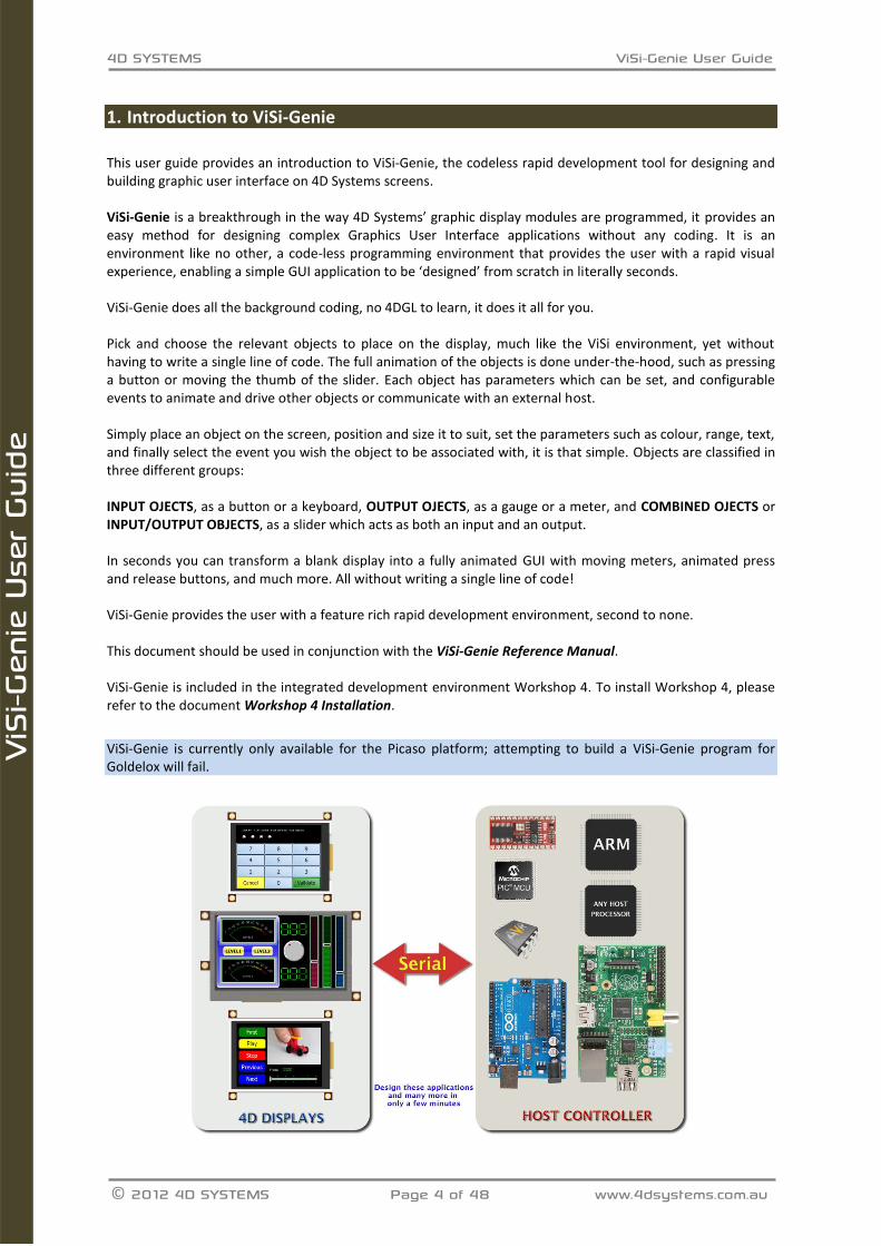
This user guide provides an introduction to ViSi-Genie, the codeless rapid development tool for designing and building graphic user interface on 4D Systems screens. ViSi-Genie is a breakthrough in the way 4D Systems’ graphic display modules are programmed, it provides an easy method for designing complex Graphics User Interface applications without any coding. It is an environment like no other, a code-less programming environment that provides the user with a rapid visual experience, enabling a simple GUI application to be ‘designed’ from scratch in literally seconds. ViSi-Genie does all the background coding, no 4DGL to learn, it does it all for you. Pick and choose the relevant objects to place on the display, much like the ViSi environment, yet without having to write a single line of code. The full animation of the objects is done under-the-hood, such as pressing a button or moving the thumb of the slider. Each object has parameters which can be set, and configurable events to animate and drive other objects or communicate with an external host. Simply place an object on the screen, position and size it to suit, set the parameters such as colour, range, text, and finally select the event you wish the object to be associated with, it is that simple. Objects are classified in three different groups: INPUT OJECTS, as a button or a keyboard, OUTPUT OJECTS, as a gauge or a meter, and COMBINED OJECTS or INPUT/OUTPUT OBJECTS, as a slider which acts as both an input and an output. In seconds you can transform a blank display into a fully animated GUI with moving meters, animated press and release buttons, and much more. All without writing a single line of code! ViSi-Genie provides the user with a feature rich rapid development environment, second to none. This document should be used in conjunction with the ViSi-Genie Reference Manual. ViSi-Genie is included in the integrated development environment Workshop 4. To install Workshop 4, please refer to the document Workshop 4 Installation.
ViSi-Genie is currently only available for the Picaso platform; attempting to build a ViSi-Genie program for Goldelox will fail.
4D SYSTEMS ViSi-Genie User Guide
© 2012 4D SYSTEMS Page 5 of 48 www.4dsystems.com.au
ViS
i-Gen
ie U
ser
Guid
e
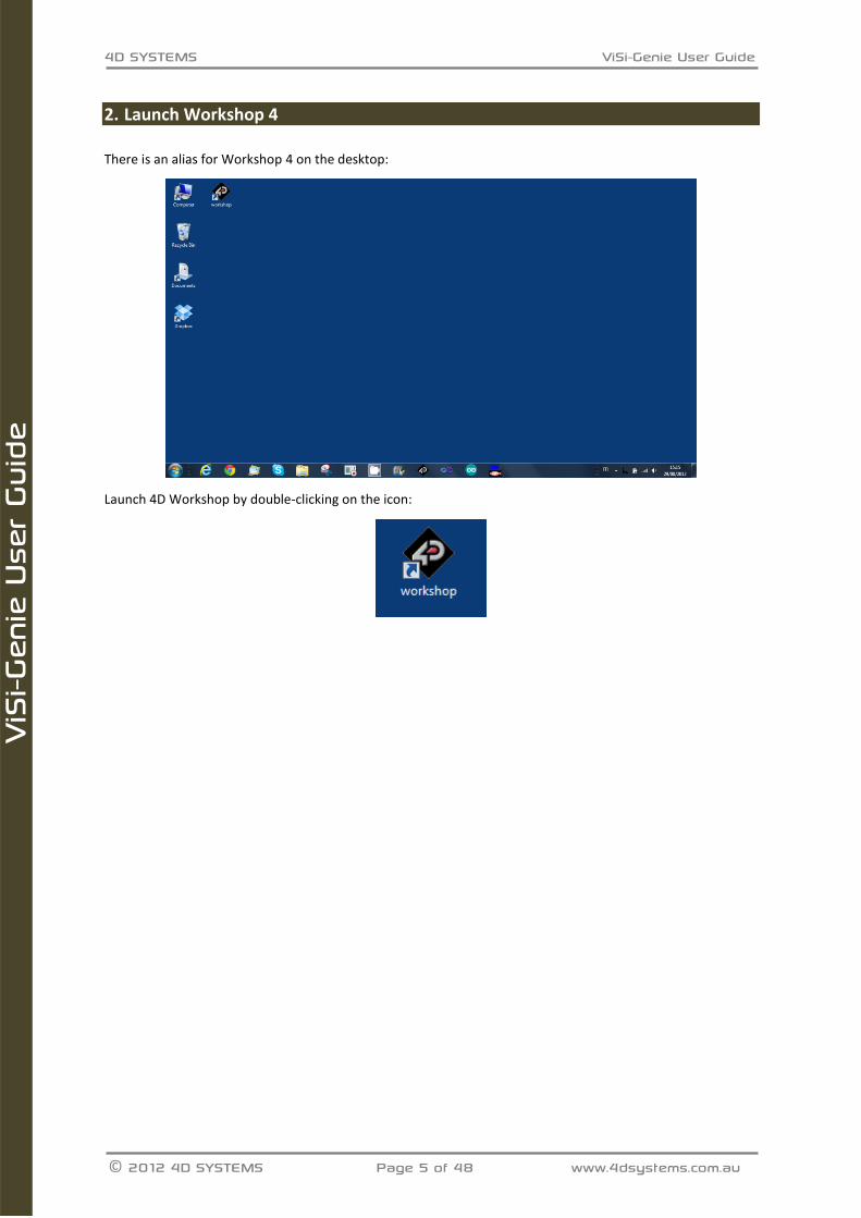
2. Launch Workshop 4
There is an alias for Workshop 4 on the desktop:
Launch 4D Workshop by double-clicking on the icon:
4D SYSTEMS ViSi-Genie User Guide
© 2012 4D SYSTEMS Page 6 of 48 www.4dsystems.com.au
ViS
i-Gen
ie U
ser
Guid
e
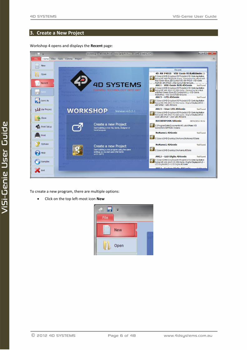
3. Create a New Project
Workshop 4 opens and displays the Recent page:
To create a new program, there are multiple options:
Click on the top left-most icon New
4D SYSTEMS ViSi-Genie User Guide
© 2012 4D SYSTEMS Page 7 of 48 www.4dsystems.com.au
ViS
i-Gen
ie U
ser
Guid
e
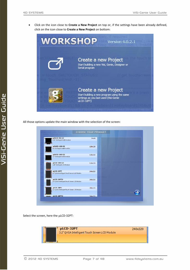
Click on the icon close to Create a New Project on top or, if the settings have been already defined,
click on the icon close to Create a New Project on bottom:
All those options update the main window with the selection of the screen:
Select the screen, here the LCD-32PT:
4D SYSTEMS ViSi-Genie User Guide
© 2012 4D SYSTEMS Page 8 of 48 www.4dsystems.com.au
ViS
i-Gen
ie U
ser
Guid
e
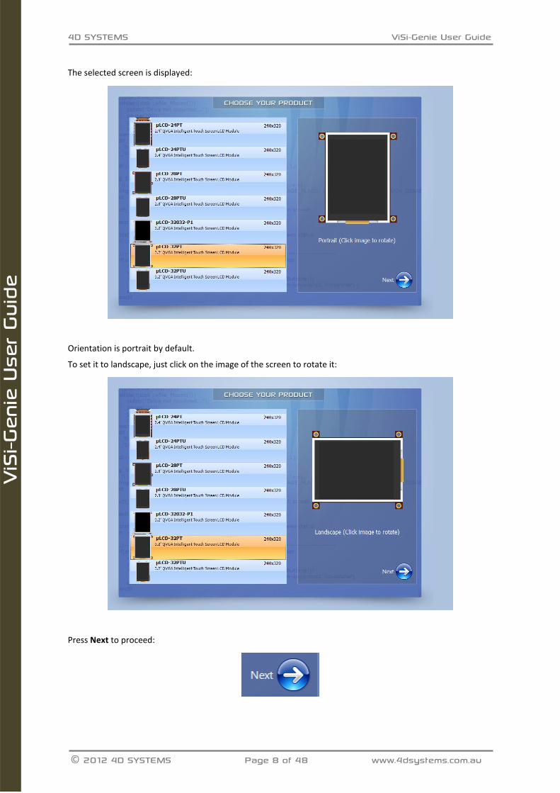
The selected screen is displayed:
Orientation is portrait by default.
To set it to landscape, just click on the image of the screen to rotate it:
Press Next to proceed:
4D SYSTEMS ViSi-Genie User Guide
© 2012 4D SYSTEMS Page 9 of 48 www.4dsystems.com.au
ViS
i-Gen
ie U
ser
Guid
e
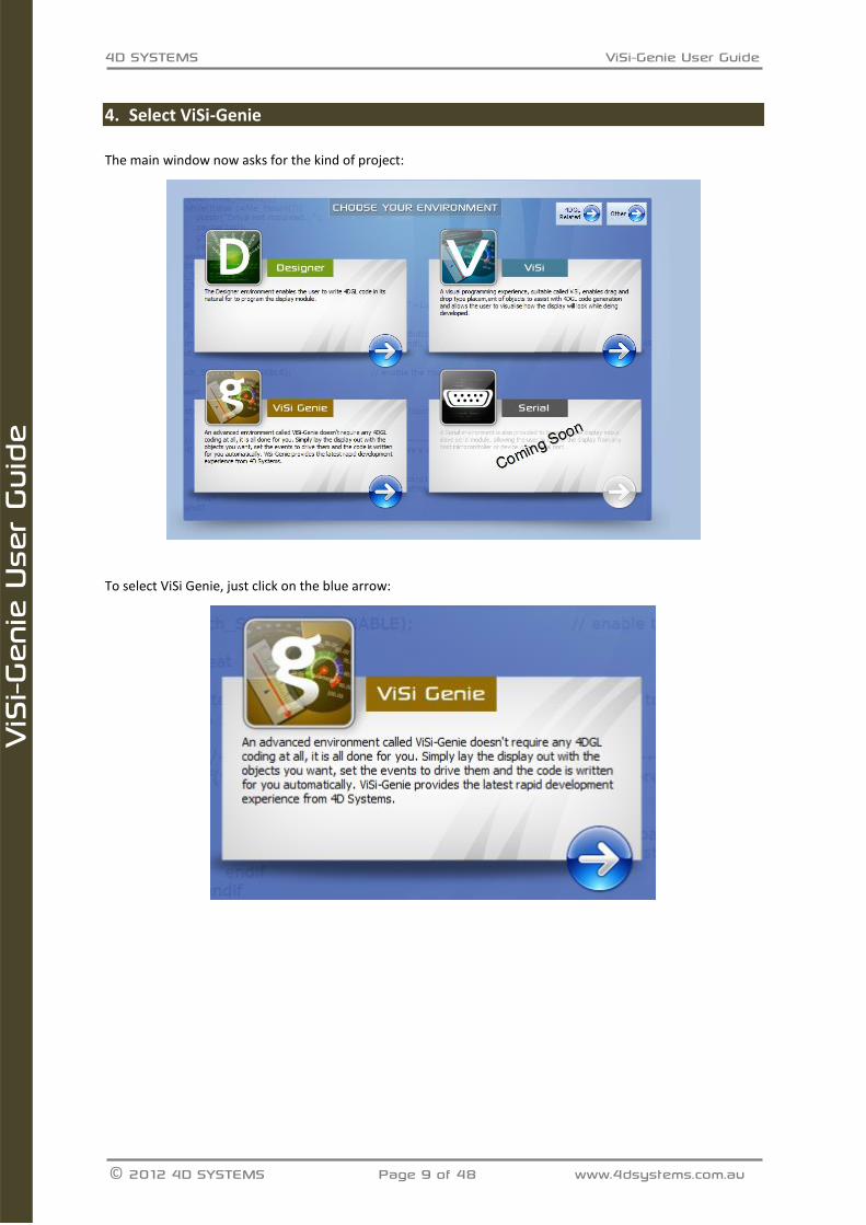
4. Select ViSi-Genie
The main window now asks for the kind of project:
To select ViSi Genie, just click on the blue arrow:
4D SYSTEMS ViSi-Genie User Guide
© 2012 4D SYSTEMS Page 10 of 48 www.4dsystems.com.au
ViS
i-Gen
ie U
ser
Guid
e
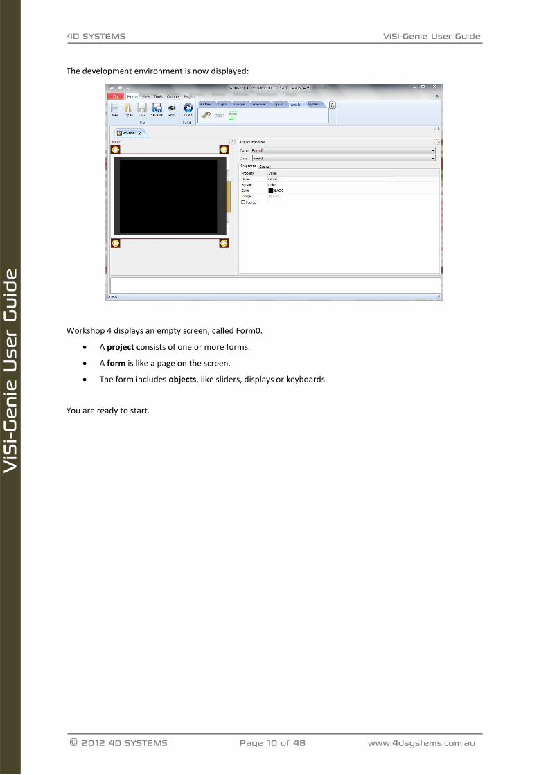
The development environment is now displayed:
Workshop 4 displays an empty screen, called Form0.
A project consists of one or more forms.
A form is like a page on the screen.
The form includes objects, like sliders, displays or keyboards.
You are ready to start.
4D SYSTEMS ViSi-Genie User Guide
© 2012 4D SYSTEMS Page 11 of 48 www.4dsystems.com.au
ViS
i-Gen
ie U
ser
Guid
e
5. The Main Screen
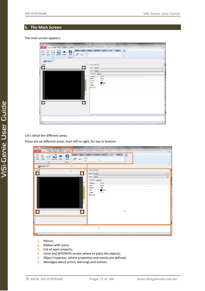
The main screen appears:
Let’s detail the different areas.
There are six different areas, from left to right, for top to bottom:
1. Menus; 2. Ribbon with icons; 3. List of open projects; 4. Form and WYSIWYG screen where to place the objects; 5. Object inspector, where properties and events are defined; 6. Messages about errors, warnings and notices.
4D SYSTEMS ViSi-Genie User Guide
© 2012 4D SYSTEMS Page 12 of 48 www.4dsystems.com.au
ViS
i-Gen
ie U
ser
Guid
e
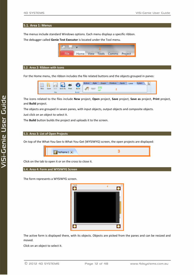
Area 1: Menus 5.1.
The menus include standard Windows options. Each menu displays a specific ribbon.
The debugger called Genie Test Executor is located under the Tool menu.
Area 2: Ribbon with Icons 5.2.
For the Home menu, the ribbon includes the file related buttons and the objects grouped in panes:
The icons related to the files include New project, Open project, Save project, Save as project, Print project,
and Build project.
The objects are grouped in seven panes, with input objects, output objects and composite objects.
Just click on an object to select it.
The Build button builds the project and uploads it to the screen.
Area 3: List of Open Projects 5.3. On top of the What-You-See-Is-What-You-Get (WYSIWYG) screen, the open projects are displayed:
Click on the tab to open it or on the cross to close it.
Area 4: Form and WYSIWYG Screen 5.4.
The form represents a WYSIWYG screen.
The active form is displayed there, with its objects. Objects are picked from the panes and can be resized and
moved.
Click on an object to select it.
4D SYSTEMS ViSi-Genie User Guide
© 2012 4D SYSTEMS Page 13 of 48 www.4dsystems.com.au
ViS
i-Gen
ie U
ser
Guid
e
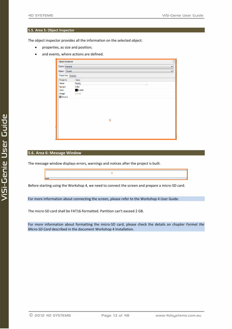
Area 5: Object Inspector 5.5.
The object inspector provides all the information on the selected object:
properties, as size and position;
and events, where actions are defined.
Area 6: Message Window 5.6.
The message window displays errors, warnings and notices after the project is built.
Before starting using the Workshop 4, we need to connect the screen and prepare a micro-SD card.
For more information about connecting the screen, please refer to the Workshop 4 User Guide.
The micro-SD card shall be FAT16-formatted. Partition can't exceed 2 GB.
For more information about formatting the micro-SD card, please check the details on chapter Format the Micro-SD Card described in the document Workshop 4 Installation.
4D SYSTEMS ViSi-Genie User Guide
© 2012 4D SYSTEMS Page 14 of 48 www.4dsystems.com.au
ViS
i-Gen
ie U
ser
Guid
e
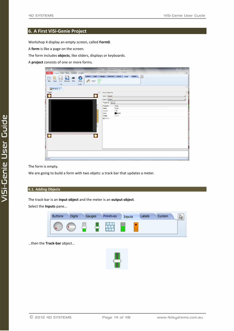
6. A First ViSi-Genie Project
Workshop 4 display an empty screen, called Form0.
A form is like a page on the screen.
The form includes objects, like sliders, displays or keyboards.
A project consists of one or more forms.
The form is empty.
We are going to build a form with two objets: a track bar that updates a meter.
Adding Objects 6.1.
The track-bar is an input object and the meter is an output object.
Select the Inputs pane...
…then the Track-bar object…
4D SYSTEMS ViSi-Genie User Guide
© 2012 4D SYSTEMS Page 15 of 48 www.4dsystems.com.au
ViS
i-Gen
ie U
ser
Guid
e
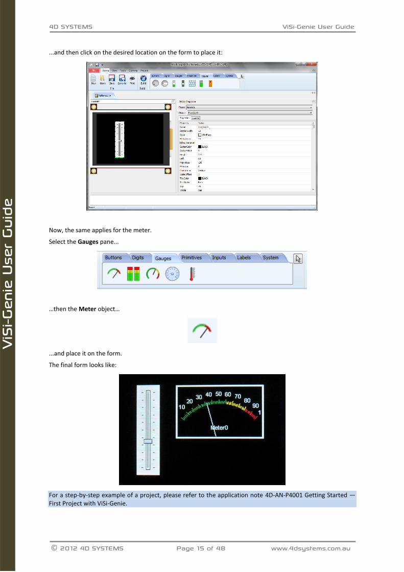
...and then click on the desired location on the form to place it:
Now, the same applies for the meter.
Select the Gauges pane...
…then the Meter object…
...and place it on the form.
The final form looks like:
For a step-by-step example of a project, please refer to the application note 4D-AN-P4001 Getting Started — First Project with ViSi-Genie.
4D SYSTEMS ViSi-Genie User Guide
© 2012 4D SYSTEMS Page 16 of 48 www.4dsystems.com.au
ViS
i-Gen
ie U
ser
Guid
e
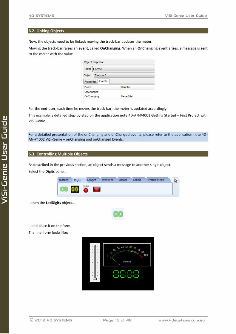
Linking Objects 6.2.
Now, the objects need to be linked: moving the track-bar updates the meter.
Moving the track-bar raises an event, called OnChanging. When an OnChanging event arises, a message is sent
to the meter with the value.
For the end-user, each time he moves the track-bar, the meter is updated accordingly.
This example is detailed step-by-step on the application note 4D-AN-P4001 Getting Started – First Project with
ViSi-Genie.
For a detailed presentation of the onChanging and onChanged events, please refer to the application note 4D-AN-P4002 ViSi-Genie – onChanging and onChanged Events.
Controlling Multiple Objects 6.3.
As described in the previous section, an object sends a message to another single object.
Select the Digits pane...
…then the LedDigits object…
...and place it on the form.
The final form looks like:
4D SYSTEMS ViSi-Genie User Guide
© 2012 4D SYSTEMS Page 17 of 48 www.4dsystems.com.au
ViS
i-Gen
ie U
ser
Guid
e
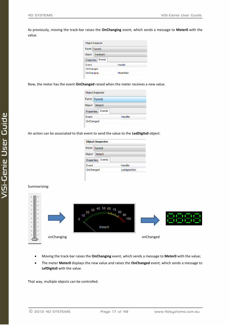
As previously, moving the track-bar raises the OnChanging event, which sends a message to Meter0 with the
value.
Now, the meter has the event OnChanged raised when the meter receives a new value.
An action can be associated to that event to send the value to the LedDigits0 object:
Summarising:
onChanging onChanged
Moving the track-bar raises the OnChanging event, which sends a message to Meter0 with the value;
The meter Meter0 displays the new value and raises the OnChanged event, which sends a message to
LefDigits0 with the value.
That way, multiple objects can be controlled.
4D SYSTEMS ViSi-Genie User Guide
© 2012 4D SYSTEMS Page 18 of 48 www.4dsystems.com.au
ViS
i-Gen
ie U
ser
Guid
e
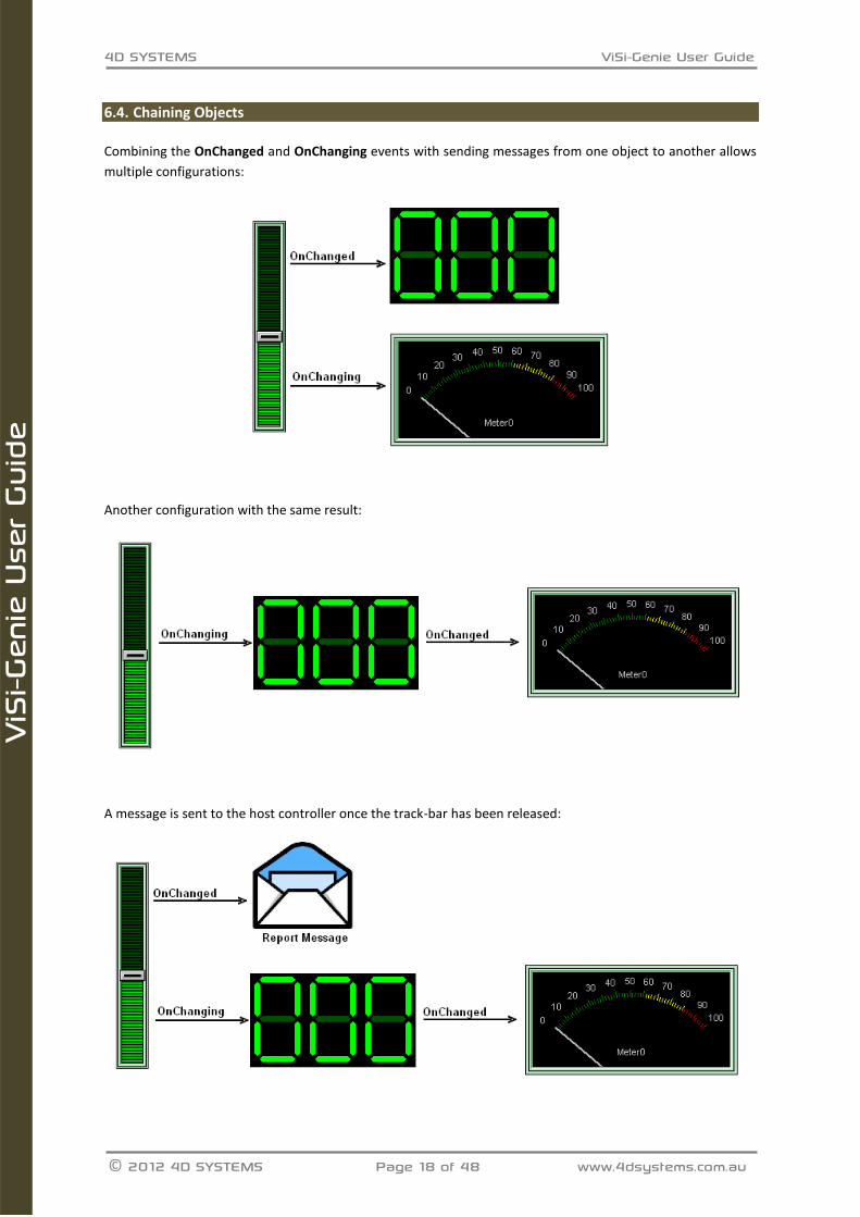
Chaining Objects 6.4.
Combining the OnChanged and OnChanging events with sending messages from one object to another allows
multiple configurations:
Another configuration with the same result:
A message is sent to the host controller once the track-bar has been released:
4D SYSTEMS ViSi-Genie User Guide
© 2012 4D SYSTEMS Page 19 of 48 www.4dsystems.com.au
ViS
i-Gen
ie U
ser
Guid
e
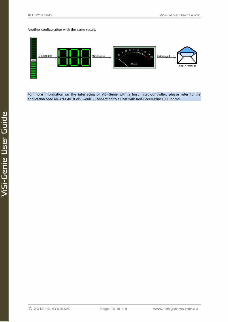
Another configuration with the same result:
For more information on the interfacing of ViSi-Genie with a host micro-controller, please refer to the application note 4D-AN-P4010 ViSi-Genie - Connection to a Host with Red-Green-Blue LED Control.
4D SYSTEMS ViSi-Genie User Guide
© 2012 4D SYSTEMS Page 20 of 48 www.4dsystems.com.au
ViS
i-Gen
ie U
ser
Guid
e
7. Objects
ViSi-Genie relies on three groups of objects:
The INPUT OBJECTS produce stimuli data for INPUT type objects or directly to Serial output. The
animation for these objects is done under the hood, for example the slider thumb movements, etc. A
button press can launch a sub-form or can send out serial data or cause another event to occur.
Example: a button.
The OUTPUT OBJECTS only react to OUTPUT stimuli. The stimulus data can come from the Serial port
or an INPUT object. They produce no input data or stimuli. The animation for these objects is
performed under the hood, for example incoming serial data can move the needle of the meter, etc.
OUTPUTs can be set regardless of whether they are displayed on the current form, when the form
containing them is displayed, they are displayed with their current value.
Example: a meter.
Actually, most objects are COMBINED OJECTS or INPUT/OUTPUT OBJECTS. Most input objects can
also function as outputs, with the notable exception of Keyboards. Certain objects need both an input
stimuli as well as produce an output event. For example, a slider thumb position may need to be
remotely controlled from incoming serial data. A button may need to be animated not only using the
touch screen but via serial data.
Example: a slider.
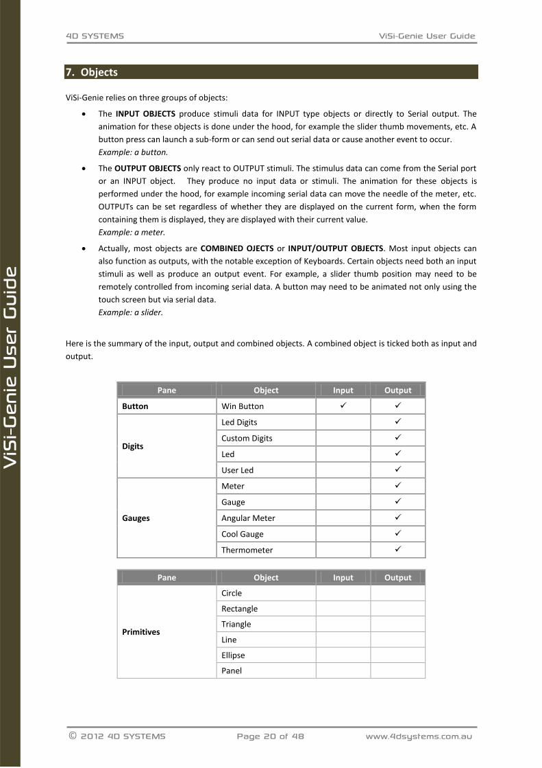
Here is the summary of the input, output and combined objects. A combined object is ticked both as input and
output.
Pane Object Input Output
Button Win Button
Digits
Led Digits
Custom Digits
Led
User Led
Gauges
Meter
Gauge
Angular Meter
Cool Gauge
Thermometer
Pane Object Input Output
Primitives
Circle
Rectangle
Triangle
Line
Ellipse
Panel
4D SYSTEMS ViSi-Genie User Guide
© 2012 4D SYSTEMS Page 21 of 48 www.4dsystems.com.au
ViS
i-Gen
ie U
ser
Guid
e
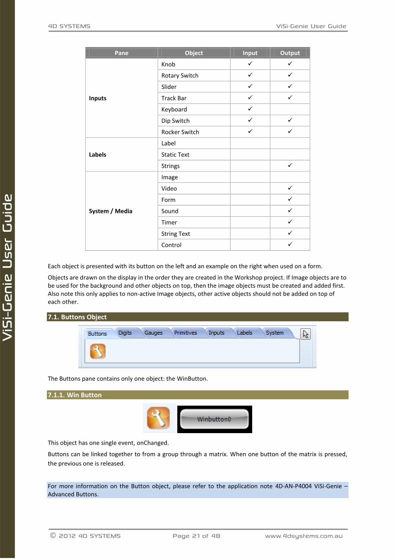
Pane Object Input Output
Inputs
Knob
Rotary Switch
Slider
Track Bar
Keyboard
Dip Switch
Rocker Switch
Labels
Label
Static Text
Strings
System / Media
Image
Video
Form
Sound
Timer
String Text
Control
Each object is presented with its button on the left and an example on the right when used on a form.
Objects are drawn on the display in the order they are created in the Workshop project. If Image objects are to be used for the background and other objects on top, then the image objects must be created and added first. Also note this only applies to non-active Image objects, other active objects should not be added on top of each other.
Buttons Object 7.1.
The Buttons pane contains only one object: the WinButton.
7.1.1. Win Button
This object has one single event, onChanged.
Buttons can be linked together to from a group through a matrix. When one button of the matrix is pressed,
the previous one is released.
For more information on the Button object, please refer to the application note 4D-AN-P4004 ViSi-Genie – Advanced Buttons.

4D SYSTEMS ViSi-Genie User Guide
© 2012 4D SYSTEMS Page 22 of 48 www.4dsystems.com.au
ViS
i-Gen
ie U
ser
Guid
e
Digits Objects 7.2.
The Digits pane contains 4 different displays.
7.2.1. LED Digits
The number of digits, the decimal place, the size, the leading zeros can be customised.
This object has one single event, onChanged, very useful to send the value received.
7.2.2. Custom Digits
This object offers no customisation.
This object has one single event, onChanged, very useful to send the value received.
7.2.3. LED
The size, the label, the font and the colour can be customised.
This object has one single event, onChanged, very useful to send the value received.
7.2.4. User LED
The size and the colour can be customised.
This object has one single event, onChanged, very useful to send the value received.
For more information on the Digits objects, please refer to the application note 4D-AN-P4012 ViSi-Genie - Digital Displays.

4D SYSTEMS ViSi-Genie User Guide
© 2012 4D SYSTEMS Page 23 of 48 www.4dsystems.com.au
ViS
i-Gen
ie U
ser
Guid
e
Gauges Objects 7.3.
The Gauges pane contains 5 specialised displays:
7.3.1. Meter
The meter displays a value in a dial. Minimum and maximum, number of intervals and scales, all colours are
fully configurable, among other options.
The meter is an output object and can send a message when changed.
This object has one single event, onChanged, very useful to send the value received.
7.3.2. Gauge
The meter displays a value in a dial. Minimun and maximum, number of intervals, scales and three palettes, all
colours are fully configurable, among other options.
The meter is an output object and can send a message when changed.
This object has one single event, onChanged, very useful to send the value received.
4D SYSTEMS ViSi-Genie User Guide
© 2012 4D SYSTEMS Page 24 of 48 www.4dsystems.com.au
ViS
i-Gen
ie U
ser
Guid
e
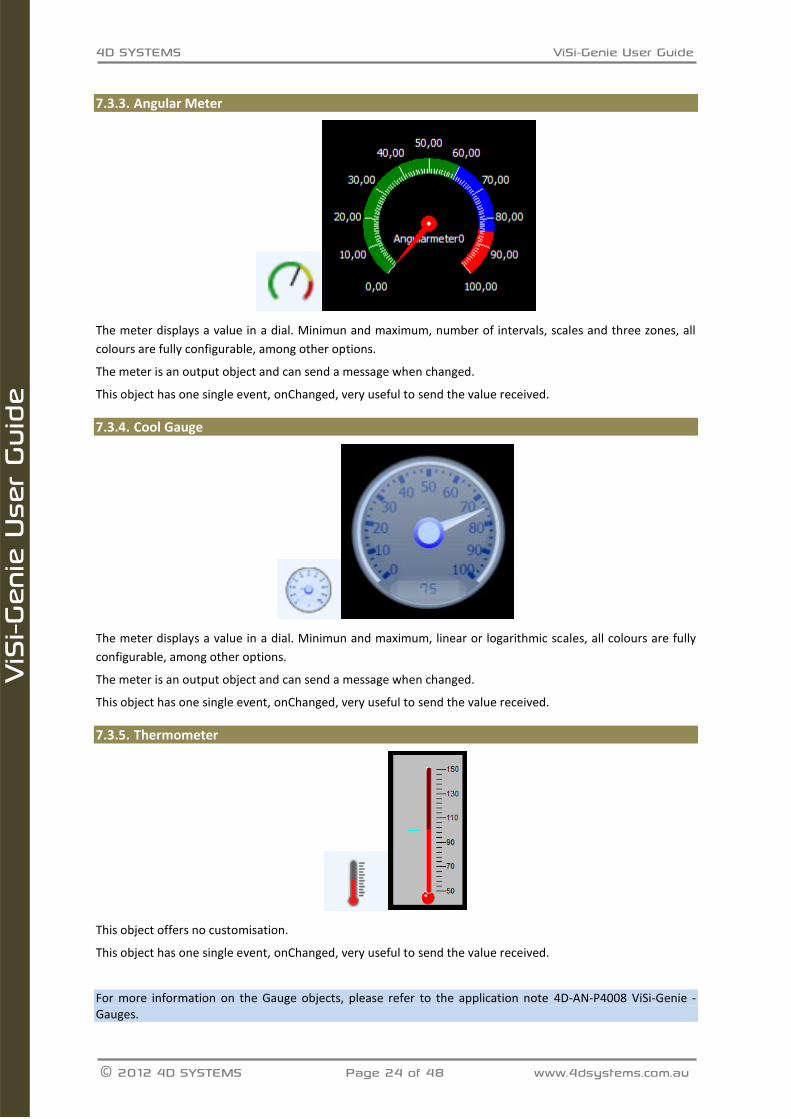
7.3.3. Angular Meter
The meter displays a value in a dial. Minimun and maximum, number of intervals, scales and three zones, all
colours are fully configurable, among other options.
The meter is an output object and can send a message when changed.
This object has one single event, onChanged, very useful to send the value received.
7.3.4. Cool Gauge
The meter displays a value in a dial. Minimun and maximum, linear or logarithmic scales, all colours are fully
configurable, among other options.
The meter is an output object and can send a message when changed.
This object has one single event, onChanged, very useful to send the value received.
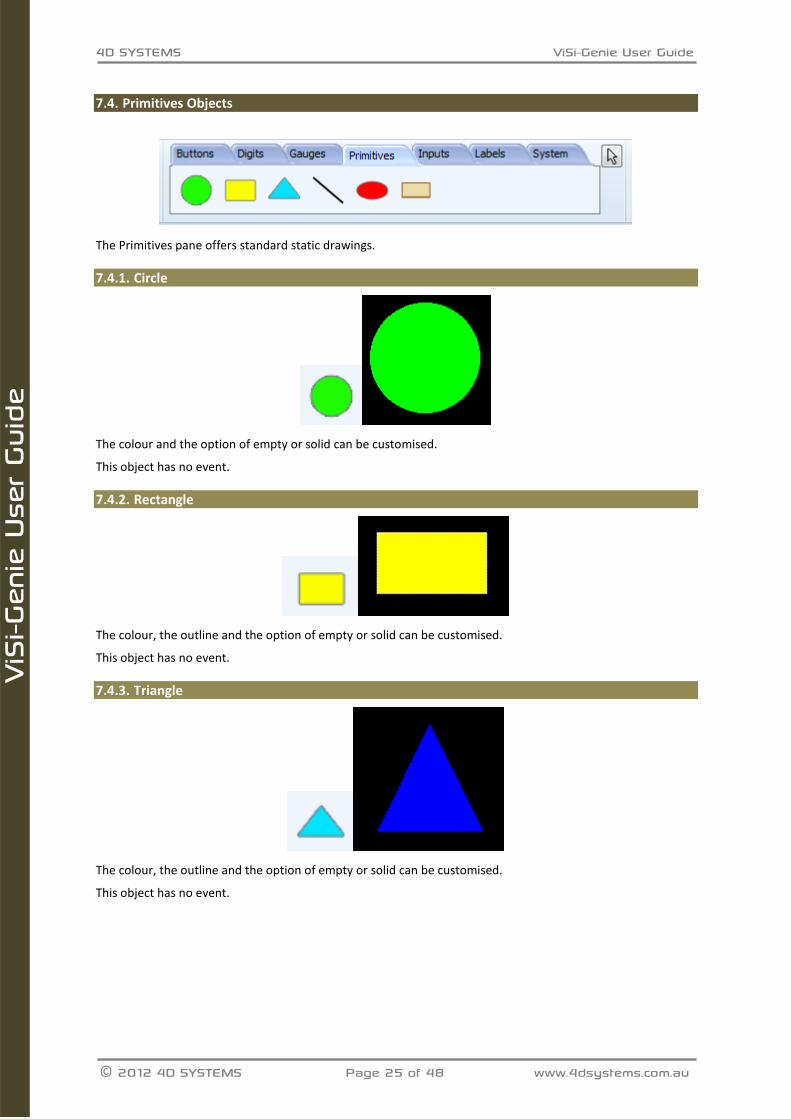
7.3.5. Thermometer
This object offers no customisation.
This object has one single event, onChanged, very useful to send the value received.
For more information on the Gauge objects, please refer to the application note 4D-AN-P4008 ViSi-Genie - Gauges.
4D SYSTEMS ViSi-Genie User Guide
© 2012 4D SYSTEMS Page 25 of 48 www.4dsystems.com.au
ViS
i-Gen
ie U
ser
Guid
e
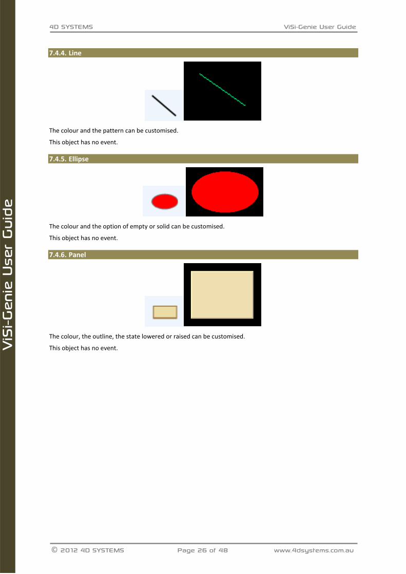
Primitives Objects 7.4.
The Primitives pane offers standard static drawings.
7.4.1. Circle
The colour and the option of empty or solid can be customised.
This object has no event.
7.4.2. Rectangle
The colour, the outline and the option of empty or solid can be customised.
This object has no event.
7.4.3. Triangle
The colour, the outline and the option of empty or solid can be customised.
This object has no event.
4D SYSTEMS ViSi-Genie User Guide
© 2012 4D SYSTEMS Page 26 of 48 www.4dsystems.com.au
ViS
i-Gen
ie U
ser
Guid
e
7.4.4. Line
The colour and the pattern can be customised.
This object has no event.
7.4.5. Ellipse
The colour and the option of empty or solid can be customised.
This object has no event.
7.4.6. Panel
The colour, the outline, the state lowered or raised can be customised.
This object has no event.
4D SYSTEMS ViSi-Genie User Guide
© 2012 4D SYSTEMS Page 27 of 48 www.4dsystems.com.au
ViS
i-Gen
ie U
ser
Guid
e
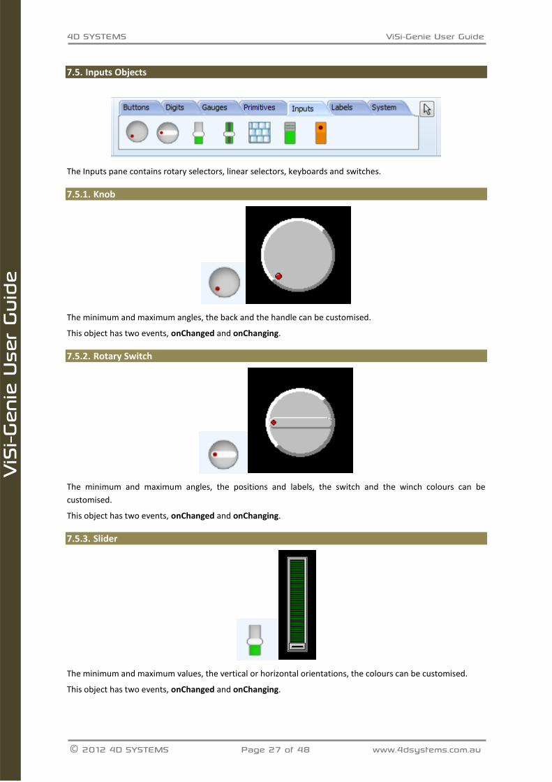
Inputs Objects 7.5.
The Inputs pane contains rotary selectors, linear selectors, keyboards and switches.
7.5.1. Knob
The minimum and maximum angles, the back and the handle can be customised.
This object has two events, onChanged and onChanging.
7.5.2. Rotary Switch
The minimum and maximum angles, the positions and labels, the switch and the winch colours can be
customised.
This object has two events, onChanged and onChanging.
7.5.3. Slider
The minimum and maximum values, the vertical or horizontal orientations, the colours can be customised.
This object has two events, onChanged and onChanging.
4D SYSTEMS ViSi-Genie User Guide
© 2012 4D SYSTEMS Page 28 of 48 www.4dsystems.com.au
ViS
i-Gen
ie U
ser
Guid
e
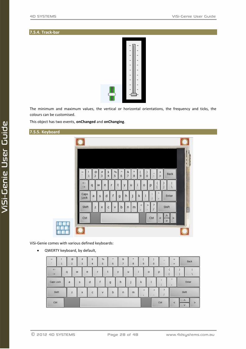
7.5.4. Track-bar
The minimum and maximum values, the vertical or horizontal orientations, the frequency and ticks, the
colours can be customised.
This object has two events, onChanged and onChanging.
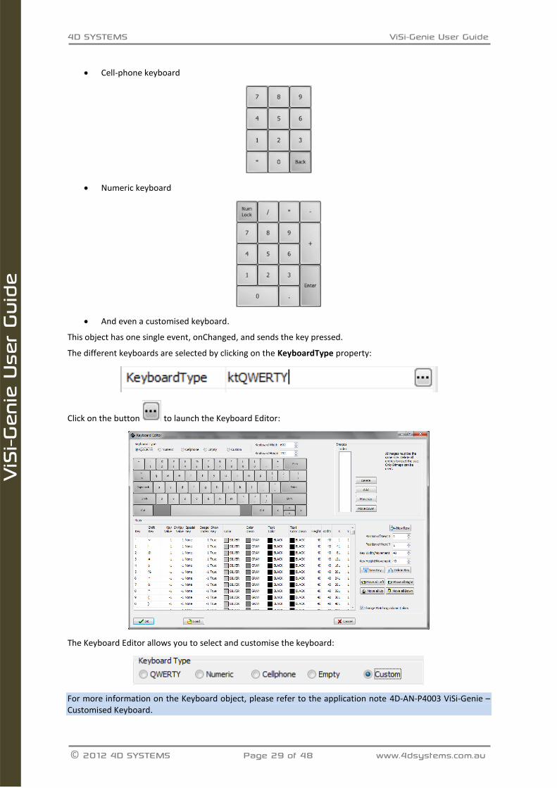
7.5.5. Keyboard
ViSi-Genie comes with various defined keyboards:
QWERTY keyboard, by default,
4D SYSTEMS ViSi-Genie User Guide
© 2012 4D SYSTEMS Page 29 of 48 www.4dsystems.com.au
ViS
i-Gen
ie U
ser
Guid
e
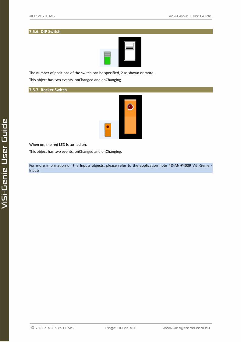
Cell-phone keyboard
Numeric keyboard
And even a customised keyboard.
This object has one single event, onChanged, and sends the key pressed.
The different keyboards are selected by clicking on the KeyboardType property:
Click on the button to launch the Keyboard Editor:
The Keyboard Editor allows you to select and customise the keyboard:
For more information on the Keyboard object, please refer to the application note 4D-AN-P4003 ViSi-Genie – Customised Keyboard.
4D SYSTEMS ViSi-Genie User Guide
© 2012 4D SYSTEMS Page 30 of 48 www.4dsystems.com.au
ViS
i-Gen
ie U
ser
Guid
e
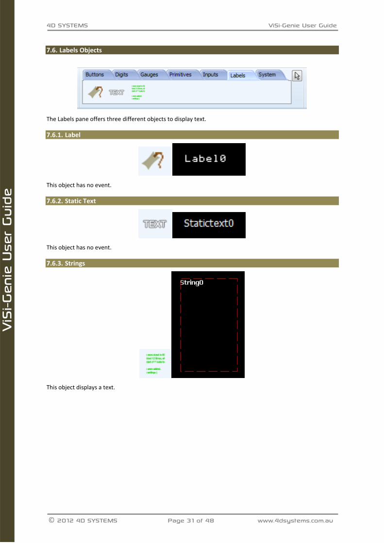
7.5.6. DIP Switch
The number of positions of the switch can be specified, 2 as shown or more.
This object has two events, onChanged and onChanging.
7.5.7. Rocker Switch
When on, the red LED is turned on.
This object has two events, onChanged and onChanging.
For more information on the Inputs objects, please refer to the application note 4D-AN-P4009 ViSi-Genie - Inputs.
4D SYSTEMS ViSi-Genie User Guide
© 2012 4D SYSTEMS Page 31 of 48 www.4dsystems.com.au
ViS
i-Gen
ie U
ser
Guid
e
Labels Objects 7.6.
The Labels pane offers three different objects to display text.
7.6.1. Label
This object has no event.
7.6.2. Static Text
This object has no event.
7.6.3. Strings
This object displays a text.
4D SYSTEMS ViSi-Genie User Guide
© 2012 4D SYSTEMS Page 32 of 48 www.4dsystems.com.au
ViS
i-Gen
ie U
ser
Guid
e
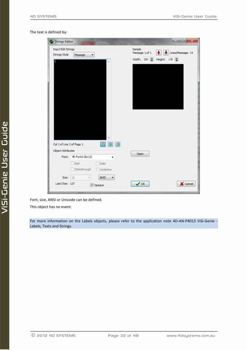
The text is defined by:
Font, size, ANSI or Unicode can be defined.
This object has no event.
For more information on the Labels objects, please refer to the application note 4D-AN-P4013 ViSi-Genie - Labels, Texts and Strings.
4D SYSTEMS ViSi-Genie User Guide
© 2012 4D SYSTEMS Page 33 of 48 www.4dsystems.com.au
ViS
i-Gen
ie U
ser
Guid
e
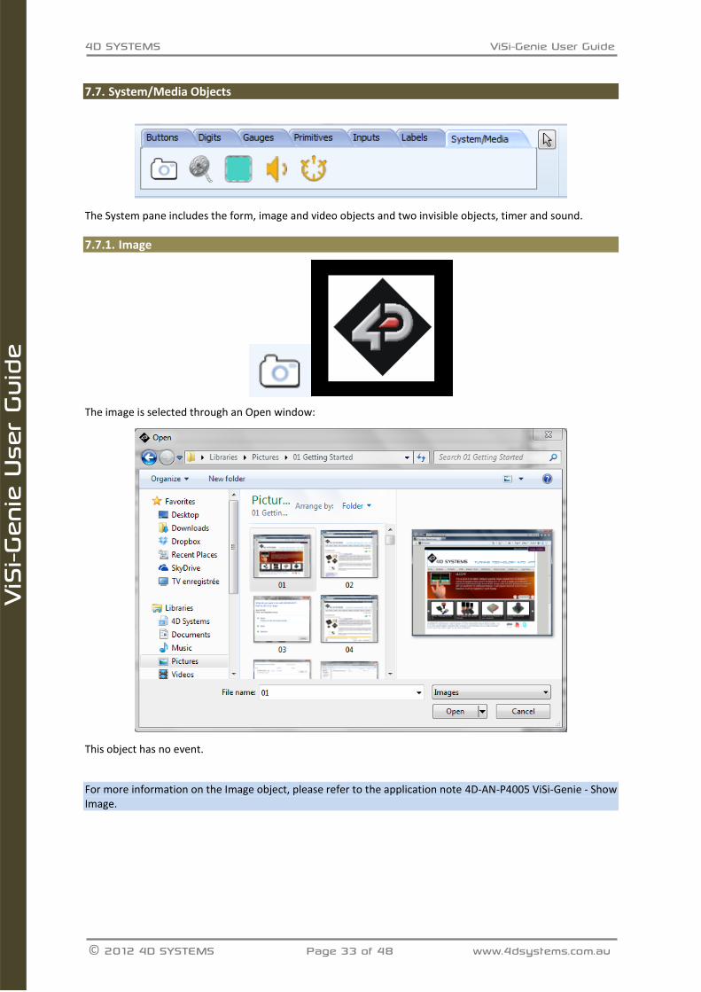
System/Media Objects 7.7.
The System pane includes the form, image and video objects and two invisible objects, timer and sound.
7.7.1. Image
The image is selected through an Open window:
This object has no event.
For more information on the Image object, please refer to the application note 4D-AN-P4005 ViSi-Genie - Show Image.
4D SYSTEMS ViSi-Genie User Guide
© 2012 4D SYSTEMS Page 34 of 48 www.4dsystems.com.au
ViS
i-Gen
ie U
ser
Guid
e
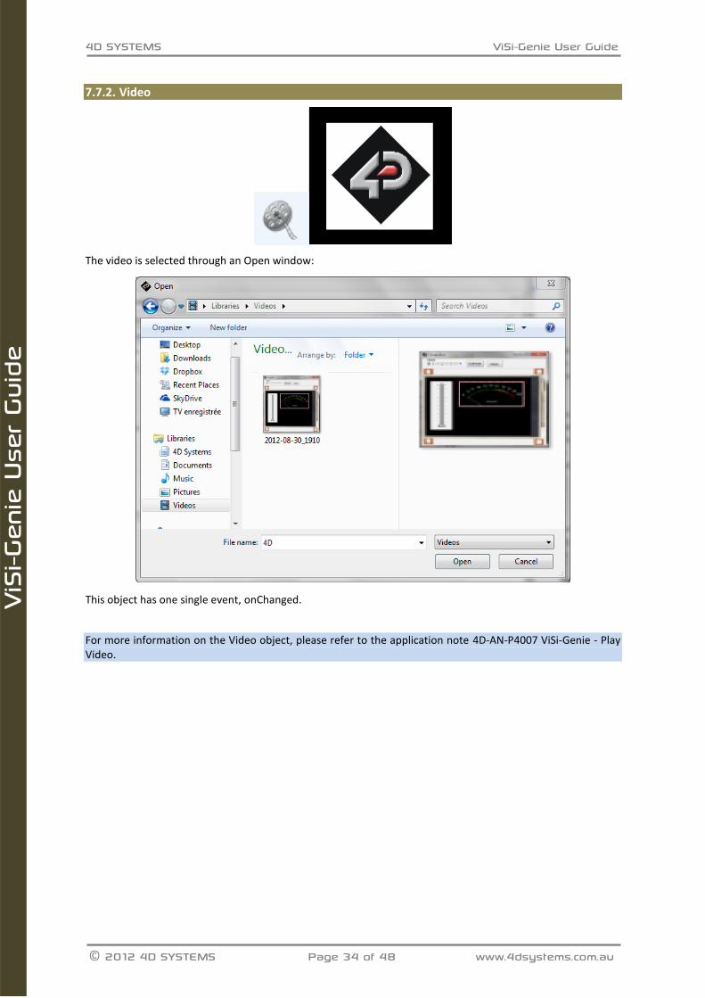
7.7.2. Video
The video is selected through an Open window:
This object has one single event, onChanged.
For more information on the Video object, please refer to the application note 4D-AN-P4007 ViSi-Genie - Play Video.
4D SYSTEMS ViSi-Genie User Guide
© 2012 4D SYSTEMS Page 35 of 48 www.4dsystems.com.au
ViS
i-Gen
ie U
ser
Guid
e
7.7.3. Form
The Form creates a new empty form and adds it to the project.
This object has one single event, onActivate.
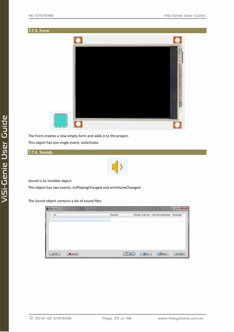
7.7.4. Sounds
Sound is an invisible object.
This object has two events, onPlayingChanged and onVolumeChanged.
The Sound object contains a list of sound files:
4D SYSTEMS ViSi-Genie User Guide
© 2012 4D SYSTEMS Page 36 of 48 www.4dsystems.com.au
ViS
i-Gen
ie U
ser
Guid
e
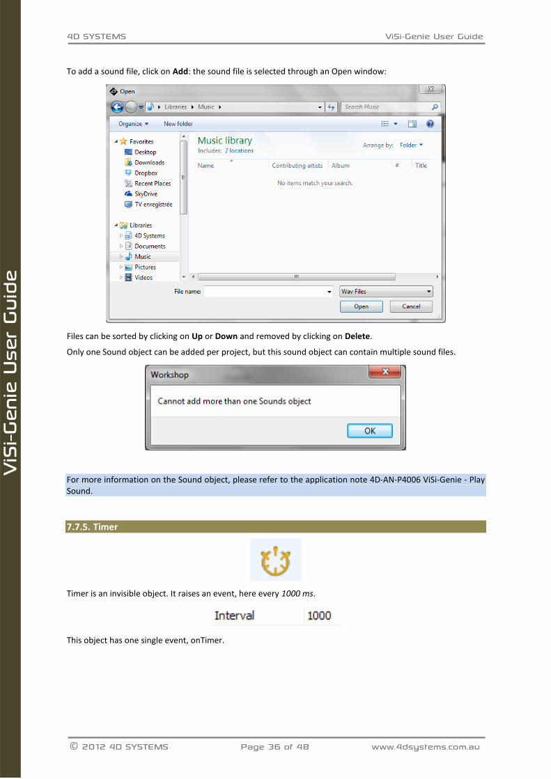
To add a sound file, click on Add: the sound file is selected through an Open window:
Files can be sorted by clicking on Up or Down and removed by clicking on Delete.
Only one Sound object can be added per project, but this sound object can contain multiple sound files.
For more information on the Sound object, please refer to the application note 4D-AN-P4006 ViSi-Genie - Play Sound.
7.7.5. Timer
Timer is an invisible object. It raises an event, here every 1000 ms.
This object has one single event, onTimer.
4D SYSTEMS ViSi-Genie User Guide
© 2012 4D SYSTEMS Page 37 of 48 www.4dsystems.com.au
ViS
i-Gen
ie U
ser
Guid
e
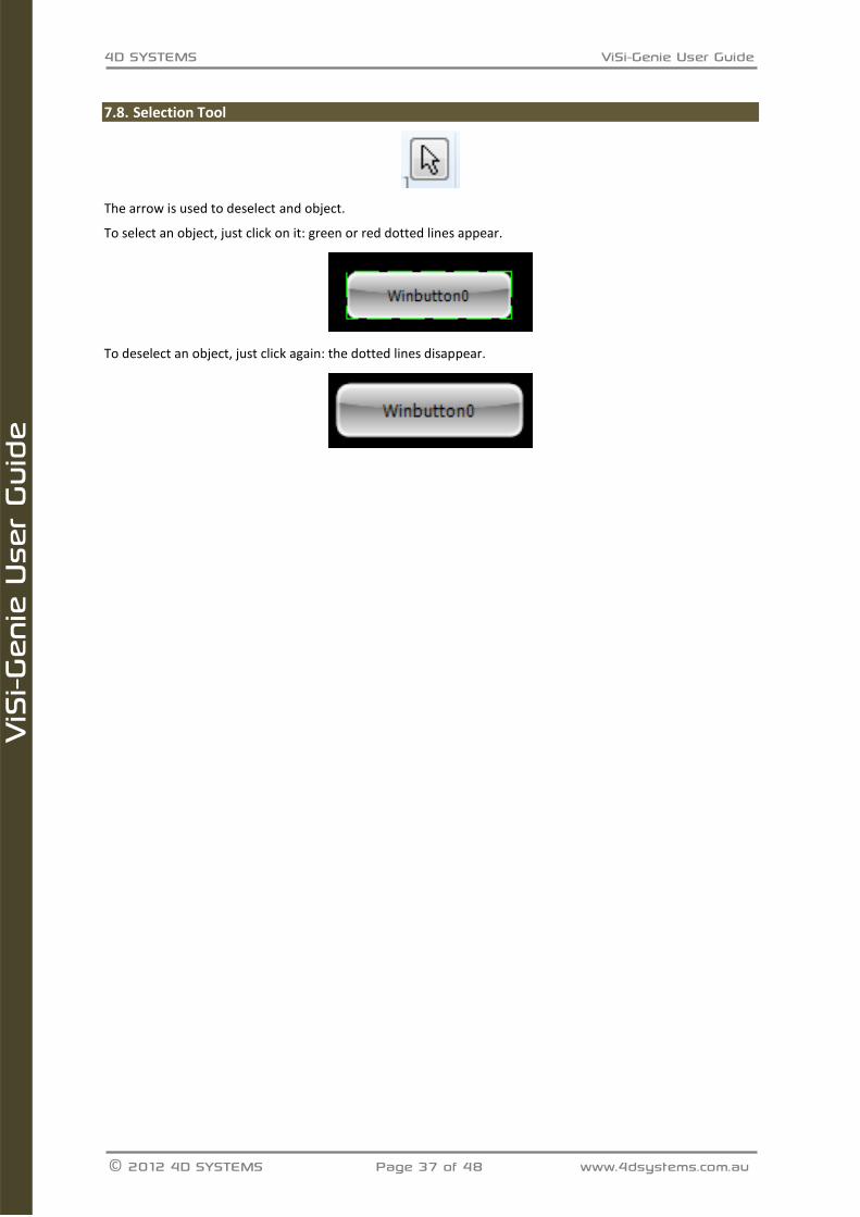
Selection Tool 7.8.
The arrow is used to deselect and object.
To select an object, just click on it: green or red dotted lines appear.
To deselect an object, just click again: the dotted lines disappear.
4D SYSTEMS ViSi-Genie User Guide
© 2012 4D SYSTEMS Page 38 of 48 www.4dsystems.com.au
ViS
i-Gen
ie U
ser
Guid
e
8. ViSi-Genie Communications Protocols
The ViSi-Genie display platform offers a serial communications protocol called the Genie Standard Protocol. The protocol provides access to a majority of the display’s features and gives the host detailed information on the current state of all the objects used in the display application.
The Genie Standard Protocol provides a simple yet effective interface between the display and the host controller and all communications are reported over this bidirectional link. The protocol utilises only a handful of commands and is simple and easy to implement. Serial data settings are:
8 Bits, No Parity, 1 Stop Bit. The baud rate for the display is selected from the Workshop Genie project. The user should match the same baud rate on the host side.
Note: RS-232 handshaking signals (i.e., RTS, CTS, DTR, and DSR) are not supported by the ViSi-Genie protocols. Instead, only the RxD (received data), TxD (transmitted data), and signal ground are used.
Objects are drawn on the display in the order they are created in the Workshop project. If Image objects are to be used for the background and other objects on top, then the image objects must be created and added first. Also note this only applies to non-active Image objects, other active objects should not be added on top of each other.
Genie Standard Protocol 8.1. This section describes the Genie Standard Protocol in detail.
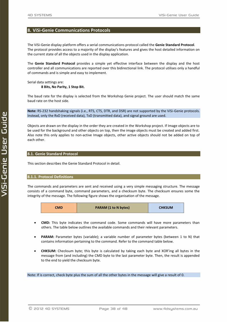
8.1.1. Protocol Definitions The commands and parameters are sent and received using a very simple messaging structure. The message consists of a command byte, command parameters, and a checksum byte. The checksum ensures some the integrity of the message. The following figure shows the organisation of the message.
CMD PARAM (1 to N bytes) CHKSUM
CMD: This byte indicates the command code. Some commands will have more parameters than others. The table below outlines the available commands and their relevant parameters.
PARAM: Parameter bytes (variable); a variable number of parameter bytes (between 1 to N) that contains information pertaining to the command. Refer to the command table below.
CHKSUM: Checksum byte; this byte is calculated by taking each byte and XOR’ing all bytes in the message from (and including) the CMD byte to the last parameter byte. Then, the result is appended to the end to yield the checksum byte.
Note: If is correct, check byte plus the sum of all the other bytes in the message will give a result of 0.
4D SYSTEMS ViSi-Genie User Guide
© 2012 4D Systems Page 39 of 48 www.4dsystems.com.au
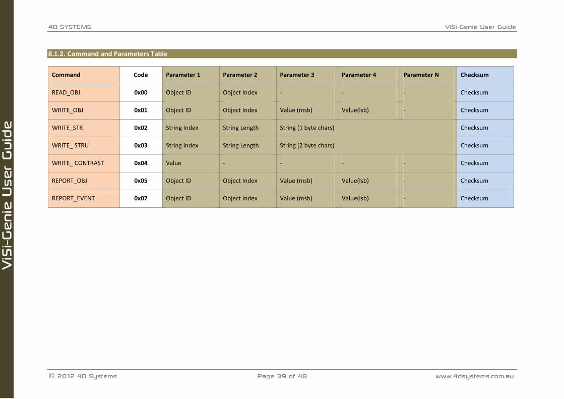
8.1.2. Command and Parameters Table
Command Code Parameter 1 Parameter 2 Parameter 3 Parameter 4 Parameter N Checksum
READ_OBJ 0x00 Object ID Object Index - - - Checksum
WRITE_OBJ 0x01 Object ID Object Index Value (msb) Value(lsb) - Checksum
WRITE_STR 0x02 String Index String Length String (1 byte chars) Checksum
WRITE_ STRU 0x03 String Index String Length String (2 byte chars) Checksum
WRITE_ CONTRAST 0x04 Value - - - - Checksum
REPORT_OBJ 0x05 Object ID Object Index Value (msb) Value(lsb) - Checksum
REPORT_EVENT 0x07 Object ID Object Index Value (msb) Value(lsb) - Checksum
4D SYSTEMS ViSi-Genie User Guide
© 2012 4D Systems Page 40 of 48 www.4dsystems.com.au
ViS
i-Gen
ie U
ser
Guid
e
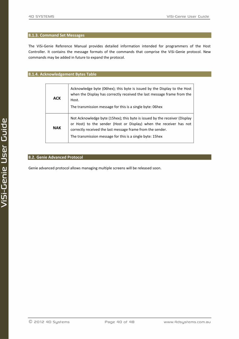
8.1.3. Command Set Messages
The ViSi-Genie Reference Manual provides detailed information intended for programmers of the Host
Controller. It contains the message formats of the commands that comprise the ViSi-Genie protocol. New
commands may be added in future to expand the protocol.
8.1.4. Acknowledgement Bytes Table
ACK
Acknowledge byte (06hex); this byte is issued by the Display to the Host
when the Display has correctly received the last message frame from the
Host.
The transmission message for this is a single byte: 06hex
NAK
Not Acknowledge byte (15hex); this byte is issued by the receiver (Display
or Host) to the sender (Host or Display) when the receiver has not
correctly received the last message frame from the sender.
The transmission message for this is a single byte: 15hex
Genie Advanced Protocol 8.2.
Genie advanced protocol allows managing multiple screens will be released soon.
4D SYSTEMS ViSi-Genie User Guide
© 2012 4D Systems Page 41 of 48 www.4dsystems.com.au
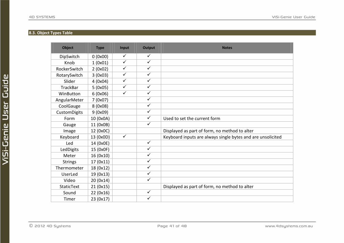
Object Types Table 8.3.
Object Type Input Output Notes
DipSwitch 0 (0x00)
Knob 1 (0x01)
RockerSwitch 2 (0x02)
RotarySwitch 3 (0x03)
Slider 4 (0x04)
TrackBar 5 (0x05)
WinButton 6 (0x06)
AngularMeter 7 (0x07)
CoolGauge 8 (0x08)
CustomDigits 9 (0x09)
Form 10 (0x0A) Used to set the current form
Gauge 11 (0x0B)
Image 12 (0x0C) Displayed as part of form, no method to alter
Keyboard 13 (0x0D) Keyboard inputs are always single bytes and are unsolicited
Led 14 (0x0E)
LedDigits 15 (0x0F)
Meter 16 (0x10)
Strings 17 (0x11)
Thermometer 18 (0x12)
UserLed 19 (0x13)
Video 20 (0x14)
StaticText 21 (0x15) Displayed as part of form, no method to alter
Sound 22 (0x16)
Timer 23 (0x17)
4D SYSTEMS ViSi-Genie User Guide
© 2012 4D Systems Page 42 of 48 www.4dsystems.com.au
ViS
i-Gen
ie U
ser
Guid
e
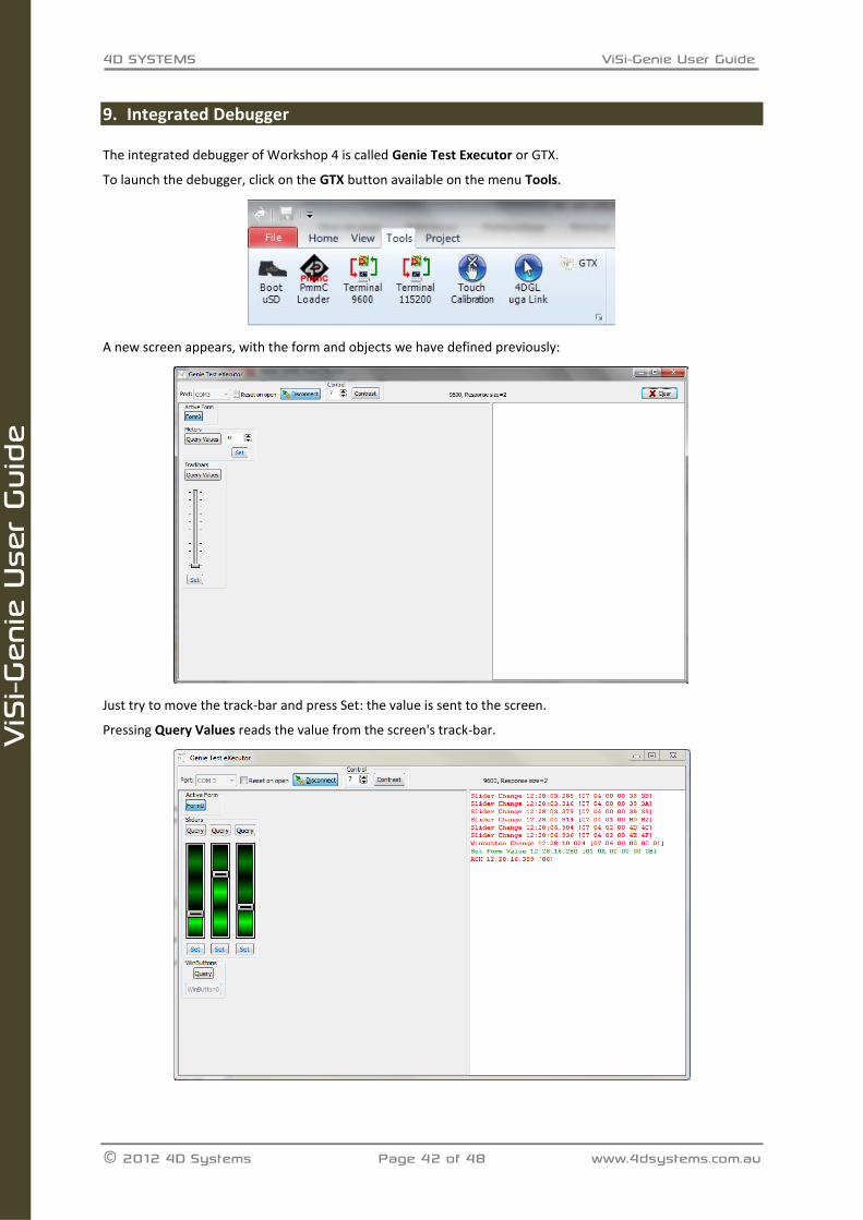
9. Integrated Debugger
The integrated debugger of Workshop 4 is called Genie Test Executor or GTX.
To launch the debugger, click on the GTX button available on the menu Tools.
A new screen appears, with the form and objects we have defined previously:
Just try to move the track-bar and press Set: the value is sent to the screen.
Pressing Query Values reads the value from the screen's track-bar.
4D SYSTEMS ViSi-Genie User Guide
© 2012 4D Systems Page 43 of 48 www.4dsystems.com.au
ViS
i-Gen
ie U
ser
Guid
e
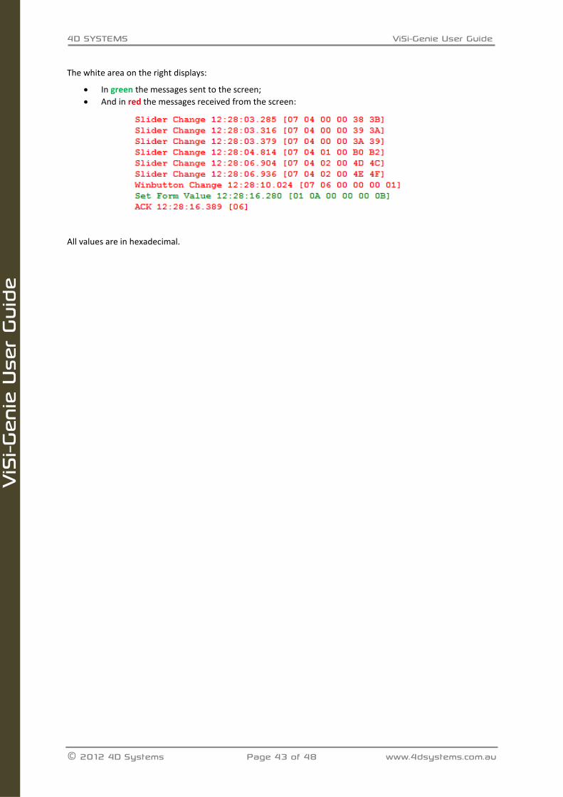
The white area on the right displays:
In green the messages sent to the screen;
And in red the messages received from the screen:
All values are in hexadecimal.
4D SYSTEMS ViSi-Genie User Guide
© 2012 4D Systems Page 44 of 48 www.4dsystems.com.au
ViS
i-Gen
ie U
ser
Guid
e
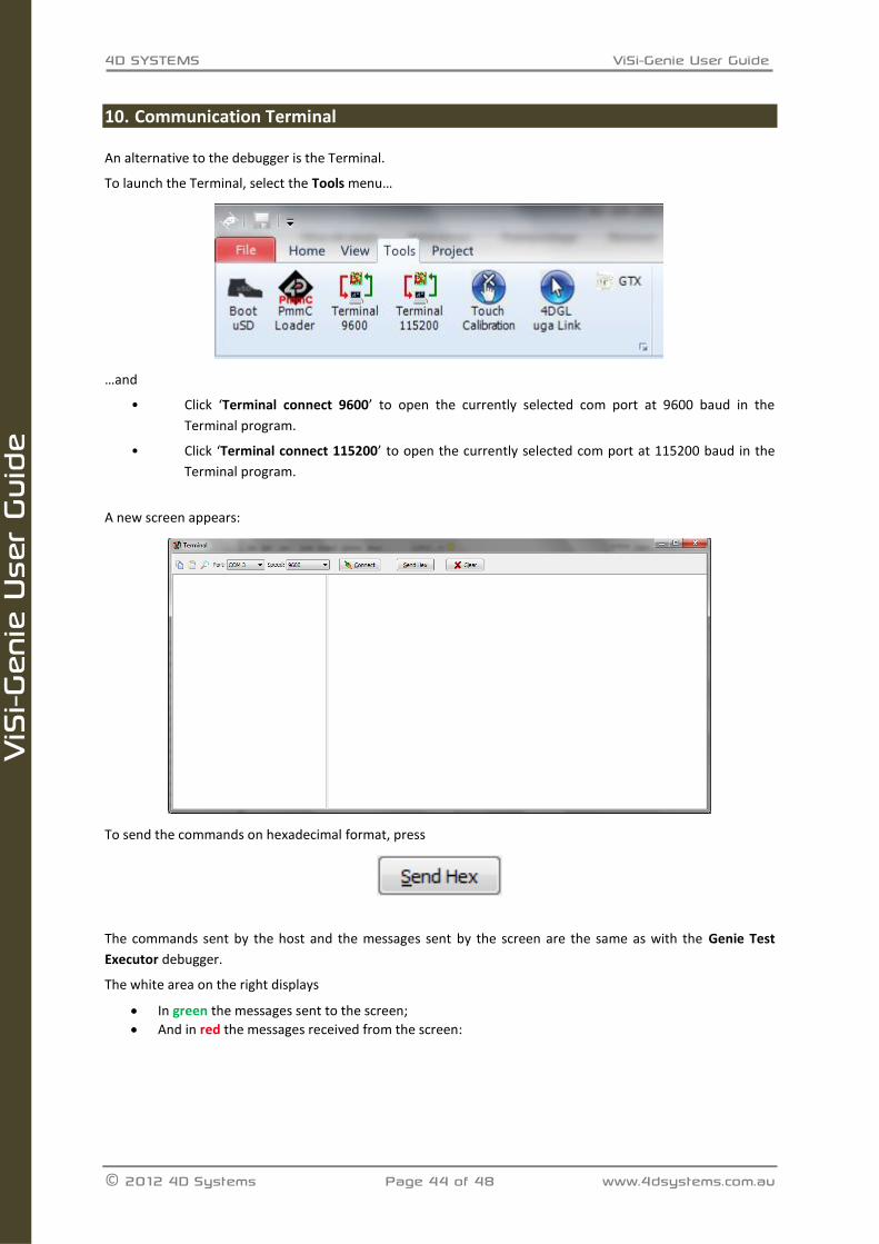
10. Communication Terminal
An alternative to the debugger is the Terminal.
To launch the Terminal, select the Tools menu…
…and
• Click ‘Terminal connect 9600’ to open the currently selected com port at 9600 baud in the
Terminal program.
• Click ‘Terminal connect 115200’ to open the currently selected com port at 115200 baud in the
Terminal program.
A new screen appears:
To send the commands on hexadecimal format, press
The commands sent by the host and the messages sent by the screen are the same as with the Genie Test
Executor debugger.
The white area on the right displays
In green the messages sent to the screen;
And in red the messages received from the screen:
4D SYSTEMS ViSi-Genie User Guide
© 2012 4D Systems Page 45 of 48 www.4dsystems.com.au
ViS
i-Gen
ie U
ser
Guid
e
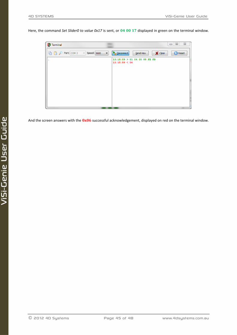
Here, the command Set Slider0 to value 0x17 is sent, or 04 00 17 displayed in green on the terminal window.
And the screen answers with the 0x06 successful acknowledgement, displayed on red on the terminal window.
4D SYSTEMS ViSi-Genie User Guide
© 2012 4D Systems Page 46 of 48 www.4dsystems.com.au
ViS
i-Gen
ie U
ser
Guid
e
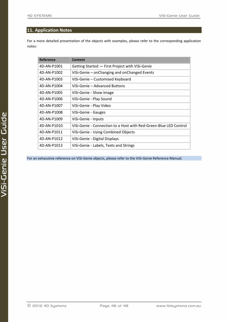
11. Application Notes
For a more detailed presentation of the objects with examples, please refer to the corresponding application
notes:
Reference Content
4D-AN-P1001 Getting Started — First Project with ViSi-Genie
4D-AN-P1002 ViSi-Genie – onChanging and onChanged Events
4D-AN-P1003 ViSi-Genie – Customised Keyboard
4D-AN-P1004 ViSi-Genie – Advanced Buttons
4D-AN-P1005 ViSi-Genie - Show Image
4D-AN-P1006 ViSi-Genie - Play Sound
4D-AN-P1007 ViSi-Genie - Play Video
4D-AN-P1008 ViSi-Genie - Gauges
4D-AN-P1009 ViSi-Genie - Inputs
4D-AN-P1010 ViSi-Genie - Connection to a Host with Red-Green-Blue LED Control
4D-AN-P1011 ViSi-Genie - Using Combined Objects
4D-AN-P1012 ViSi-Genie - Digital Displays
4D-AN-P1013 ViSi-Genie - Labels, Texts and Strings
For an exhaustive reference on ViSi-Genie objects, please refer to the ViSi-Genie Reference Manual.

4D SYSTEMS ViSi-Genie User Guide
© 2012 4D SYSTEMS Page 47 of 48 www.4dsystems.com.au
12. Revision History
Revision Revision Content Revision Date
1.0 First Release Nov 19, 2012
1.1 Fixed protocol information which was incorrect Mar 21, 2013

4D SYSTEMS ViSi-Genie User Guide
© 2012 4D SYSTEMS Page 48 of 48 www.4dsystems.com.au
13. Legal Notice Proprietary Information The information contained in this document is the property of 4D Systems Pty. Ltd. and may be the subject of patents pending or granted, and must not be copied or disclosed without prior written permission. 4D Systems endeavours to ensure that the information in this document is correct and fairly stated but does not accept liability for any error or omission. The development of 4D Systems products and services is continuous and published information may not be up to date. It is important to check the current position with 4D Systems. 4D Systems reserves the right to modify, update or makes changes to Specifications or written material without prior notice at any time. All trademarks belong to their respective owners and are recognised and acknowledged. Disclaimer of Warranties & Limitation of Liability 4D Systems makes no warranty, either expressed or implied with respect to any product, and specifically disclaims all other warranties, including, without limitation, warranties for merchantability, non-infringement and fitness for any particular purpose. Information contained in this publication regarding device applications and the like is provided only for your convenience and may be superseded by updates. It is your responsibility to ensure that your application meets with your specifications. Images and graphics used throughout this document are for illustrative purposes only. All images and graphics used are possible to be displayed on the 4D Systems range of products, however the quality may vary. In no event shall 4D Systems be liable to the buyer or to any third party for any indirect, incidental, special, consequential, punitive or exemplary damages (including without limitation lost profits, lost savings, or loss of business opportunity) arising out of or relating to any product or service provided or to be provided by 4D Systems, or the use or inability to use the same, even if 4D Systems has been advised of the possibility of such damages. 4D Systems products are not fault tolerant nor designed, manufactured or intended for use or resale as on line control equipment in hazardous environments requiring fail – safe performance, such as in the operation of nuclear facilities, aircraft navigation or communication systems, air traffic control, direct life support machines or weapons systems in which the failure of the product could lead directly to death, personal injury or severe physical or environmental damage (‘High Risk Activities’). 4D Systems and its suppliers specifically disclaim any expressed or implied warranty of fitness for High Risk Activities. Use of 4D Systems’ products and devices in 'High Risk Activities' and in any other application is entirely at the buyer’s risk, and the buyer agrees to defend, indemnify and hold harmless 4D Systems from any and all damages, claims, suits, or expenses resulting from such use. No licenses are conveyed, implicitly or otherwise, under any 4D Systems intellectual property rights.
14. Contact Information
For Technical Support: [email protected]
For Sales Support: [email protected]
Website: www.4dsystems.com.au
Copyright 4D Systems Pty. Ltd. 2000-2012.