worksheet electrical 1
TRANSCRIPT
1/10 Name
Diagnosis Technician Work Sheet
Electrical 1>>Starting System
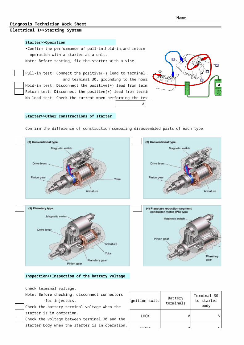
Starter>>Operation
•Confirm the performance of pull-in,hold-in,and return
operation with a starter as a unit.
Note: Before testing, fix the starter with a vise.
Pull-in test: Connect the positive(+) lead to terminal 50
and terminal 30, grounding to the housing.
Hold-in test: Disconnect the positive(+) lead from terminal 30.
Return test: Disconnect the positive(+) lead from terminal 50.
No-load test: Check the current when performing the test.
A
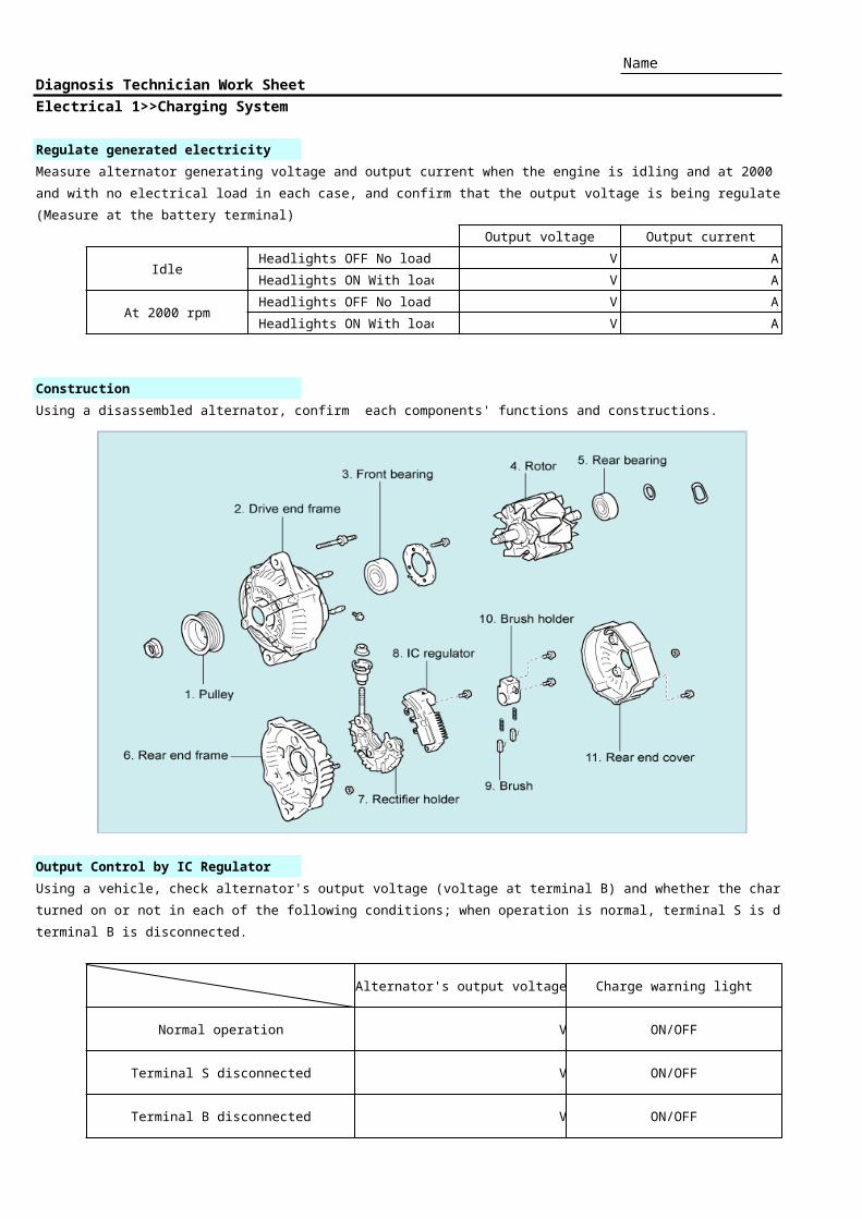
Starter>>Other constructions of starter
Confirm the difference of construction comparing disassembled parts of each type.
Inspection>>Inspection of the battery voltage
Check terminal voltage.
Note: Before checking, disconnect connectors
Ignition switch for injectors.
Check the battery terminal voltage when the
starter is in operation.LOCK V V V
Check the voltage between terminal 30 and the
starter body when the starter is in operation.START V V V
Batteryterminals
Terminal 30to starter body
Terminal 50to starter body

2/10Check the voltage between terminal 50 and the START V V V
starter body when the starter is in operation.

3/10 Name
Diagnosis Technician Work Sheet
Electrical 1>>Charging System
Regulate generated electricity
Measure alternator generating voltage and output current when the engine is idling and at 2000 rpm, with electrical load
and with no electrical load in each case, and confirm that the output voltage is being regulated.
(Measure at the battery terminal)
Output voltage Output current
Idle Headlights OFF No load V A
Headlights ON With load V A
At 2000 rpm Headlights OFF No load V A
Headlights ON With load V A
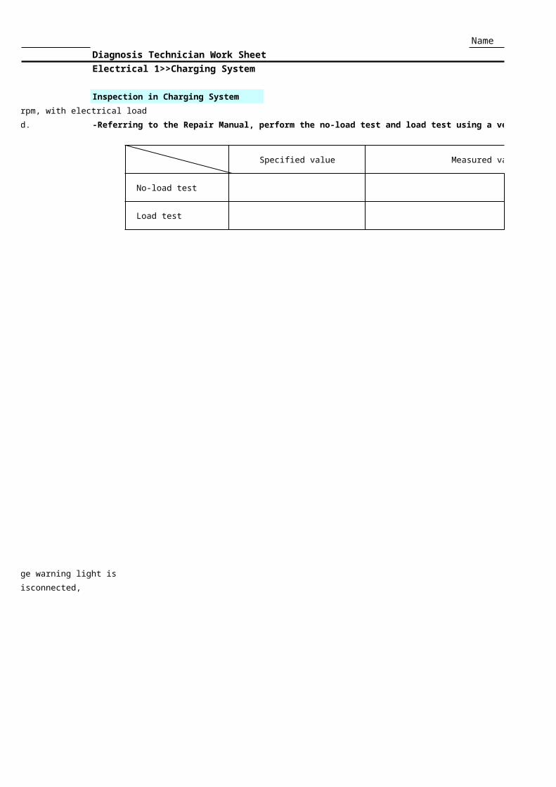
Construction
Using a disassembled alternator, confirm each components' functions and constructions.
Output Control by IC Regulator
Using a vehicle, check alternator's output voltage (voltage at terminal B) and whether the charge warning light is
turned on or not in each of the following conditions; when operation is normal, terminal S is disconnected,
terminal B is disconnected.
Alternator's output voltage Charge warning light
Normal operation V ON/OFF
Terminal S disconnected V ON/OFF
Terminal B disconnected V ON/OFF

4/10 Name
Diagnosis Technician Work Sheet
Electrical 1>>Charging System
Inspection in Charging System
-Referring to the Repair Manual, perform the no-load test and load test using a vehicle.
Specified value Measured value
No-load test V V ( A )
Load test A A ( V )
5/10 Name
Diagnosis Technician Work Sheet
Electrical 1 >>Lighting System
Operation>>Turn Signal and Hazard Warning System1. Remove a bulb from the turn signal light and check the number of flashing.
When normal Without one of the bulbs/min. /min.
2. Check if the turn signal operates or not when the HAZARD fuse is removed and the ignition switch is ON.
Vehicle model Yes No
Operation>>Front and Rear Fog Light SystemCheck the prevention function for forgetting to turn off the rear fog light.
1. Turn the light control switch on.
2. Turn on the rear fog light.
4. Check the rear fog light remains off when the light control switch is turned on again.
Operation>>Rear Light Warning System1. Remove one of the bulbs from the stop light.2. Check the warning light comes on when depressing the brake pedal during idling.
3. Check the warning light goes off after reinstalling the bulb during idling.4. Remove one of the bulbs from the taillight.
5. Check the warning light comes on when turn on the taillight during idling.6. Check the warning light goes off after reinstalling the bulb during idling.
Operation>>Light Reminder Buzzer System1. Turn the ignition switch ON and the light control switch to the HEAD or TAIL position.2. Turn the ignition switch from the ON position to the ACC or LOCK position.3. Check if there is a beeping sound when opening the driver's door.
Operation>>Light Auto Turn-Off System1. Turn the ignition switch ON and the light control switch to the HEAD position.2. Turn the ignition switch from the ON position to the ACC or LOCK position.3. Check if the headlights or head and tail lights automatically go off when opening the driver's door.
Operation>>Automatic Light Control SystemCheck the lights automatically come on when the sensor is in shade with the ignition switch ON, and the light control switch is in AUTO position.
Operation>>Headlight Leveling SystemCheck the change of the headlight beam angle via the level control switch with turning the ignition switch ON.
Operation>>Illuminated Entry SystemTurn the room light switch to the "DOOR" position.
Check the room light goes off for 5 to 15 seconds after the doors are closed.Check the room light goes off soon after the door is locked with the room lights on.
(If possible, check the interior light reminder system.)
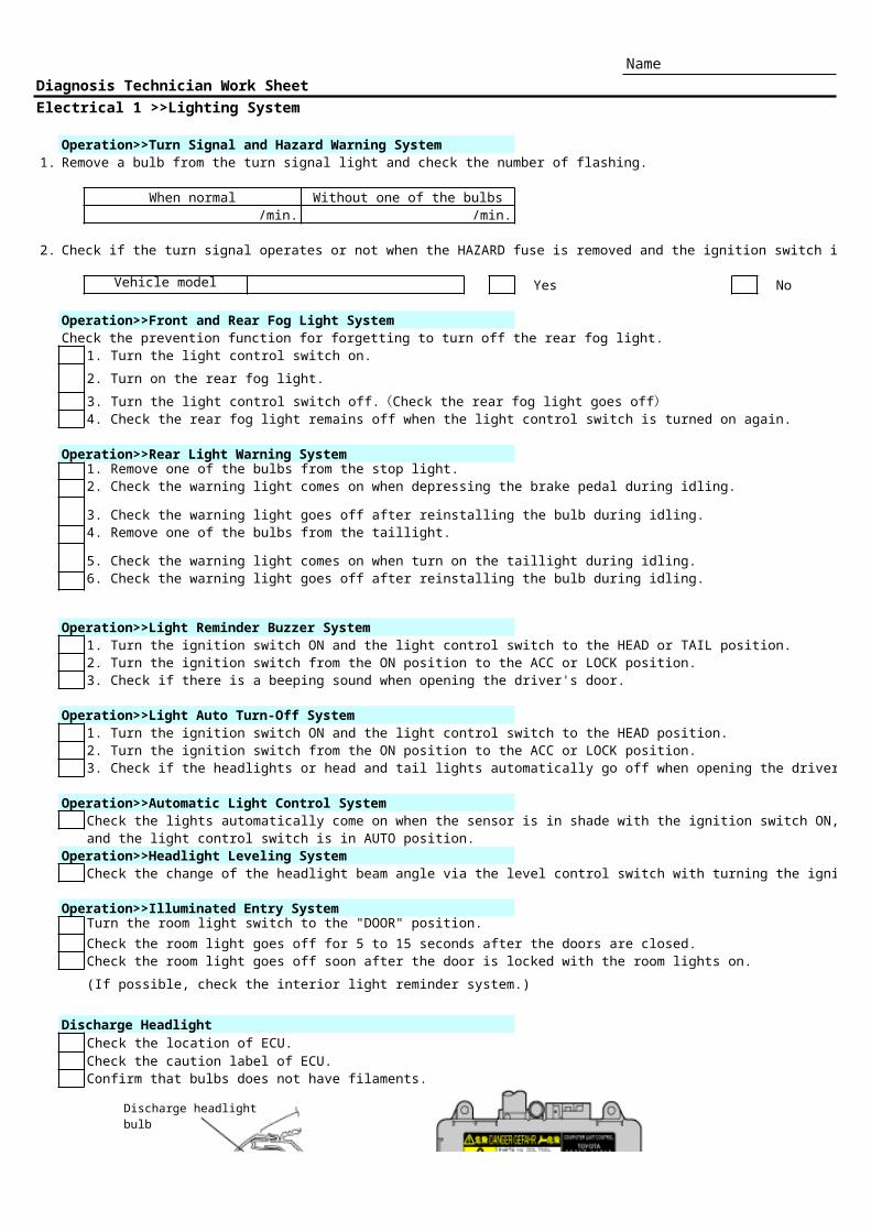
Discharge Headlight
Check the caution label of ECU.Confirm that bulbs does not have filaments.
3. Turn the light control switch off.(Check the rear fog light goes off)
Check the location of ECU.
Discharge headlight bulb
6/10
Light control ECULight control ECU

7/10 Name
Diagnosis Technician Work Sheet
Electrical 1>>Wiper and Washer System
Operation>>Wiper Operation
1. Check the wiper switch terminal voltage while cheking the wiper movement when the wiper switch is switched.
(For NZE12#, ZZE12# COROLLA LHD, terminal +1=7, +2=9, S=6, and for RHD, terminal +1=4, +2=2, S=5)
For other vehicles, refer to each EWD.
Terminal Wiper switch Specified value Checked voltage
+1 - Body ground LO Battery voltage
HI Battery voltage
OFF (Wiper is moving) Battery voltage
OFF (Wiper stopped) 0 V
+2 - Body ground LO Approx. Half of the battery voltage
HI Battery voltage
OFF (Wiper is moving) Approx. Half of the battery voltage
OFF (Wiper stopped) 0 V
S - Body ground LO 0V/Battery voltage
HI 0V/Battery voltage
OFF (Wiper is moving) Battery voltage
OFF (Wiper stopped) 0 V
2. Remove the wiper motor terminal S to check the wiper arm operation.
- Write down the wiper arm movement when the wiper switch is turned off.
8/10 Name
Diagnosis Technician Work Sheet
Electrical 1>>Door Lock Control System
Pre-operation: Leave the door window fully open.
Outline>>Function
Using an actual vehicle, check the following function.
1. Manual Door Lock /Unlock Function
2. Door Key Linked Lock/Unlock Function
3. Two-Step Unlock Function
4. Key Confine Prevention Function
(1) Check the function with the key removed from the ignition key cylinder:
Open the driver's door to check that it has been locked with the door lock knob.
(2) Check the function with the key left in the ignition key cylinder:
Open the driver's door to check that it has not been locked with the door lock knob.
5. Security Function
(1) Lock all the doors with the key and check the function:
Check that operating the door lock control switch cannot unlock the doors.
(2) Lock all the doors with the door lock control switch and the driver's door without using a key,
and check the function:
Check that operating the door lock control switch cannot unlock the doors.
(3) Lock all the doors with the door lock control switch and check the function:
Check that operating the door lock control switch can unlock the doors.

9/10 Name
Diagnosis Technician Work Sheet
Electrical 1>>Wireless Door Lock Remote Control System
Pre-operation: Leave the door window fully open.
Outline>>Function
1. Check each function using an actual vehicle and transmitter.
Transmitter Operation Check Function
All Doors Lock/Unlock Function
Two step Unlock Function
Answer Back Function
Luggage Door Open Function
Interior Light Function
Automatic Lock Function
Power Window Open/Close Function
Panic Alarm Function
2. Customize the power window open function using a hand-held tester.
(1) Check the initial setting w/ function w/o function
(2) Change the setting w/ function w/o function
(3) Initialize the setting w/ function w/o function
3. Register/Delete the recognition code referring to the applicable Repair Manual.
(1) Delete the recognition code (prohibition mode) using the ignition key and transmitter.
Delete the transmitter recognition code.
Check that the doors cannot be locked/unlocked with the transmitter
(2) Register the recognition code (add mode) using the ignition key and transmitter.
Register a transmitter recognition code
Check that the doors can be locked/unlocked with the transmitter

10/10 Name
Diagnosis Technician Work Sheet
Electrical 1>>Power Window System
Location
Check the following components installation
position and perform window up/down operation
to check the window movement.
Window regulator
Power window motor
Components
Using a disassenbled power window motor,
Speed sensor
Limit switch
Cam plate
Operation
1. Manual OPEN/CLOSE function
Check manual OPEN operation.
Check manual CLOSE operation.
2. One touch auto OPEN/CLOSE function
Check auto OPEN operation.
Check auto CLOSE operation.
3. Jam protection function
Operate the jam protection function with a hammer handle caught in the power window.
( Be careful not to pinch fingers when checking this operation.)
1. Check the jam protection function operation.
2. Check how many millimeters the window is lowered after jamming is detected.
mm
3. Check the method of resetting power window motor
referring to the Repair Manual.
4. Key-off power window function
Check the power window operates for 45 seconds before the door is opened,
even if the ignition switch is turned from the ON position to the ACC or LOCK position.
check the component operations and functions.