working with scanned data in...
TRANSCRIPT

Working with Scanned Data in SolidWorksDigital Modeling Series
This tutorial covers how to import and build geometry relative to scan data in SolidWorks. Students will learn how to orient their scan files prior to importing by using Autodesk Remake. Once the scan data is imported, a series of cross-sectional curves are created that become the profile curves for a loft surfaces. An extruded surface is then create that represents the profile shape of the form. The loft surface is then trim to the extruded surface and made into a solid with the thicken tool.
Prof. Tim PurdySchool of Industrial Design
Georgia Tech
ID@
GT
© 2
017,
Pro
f. P
urdy
SolidWorks - Working with Scanned Data
Page 1
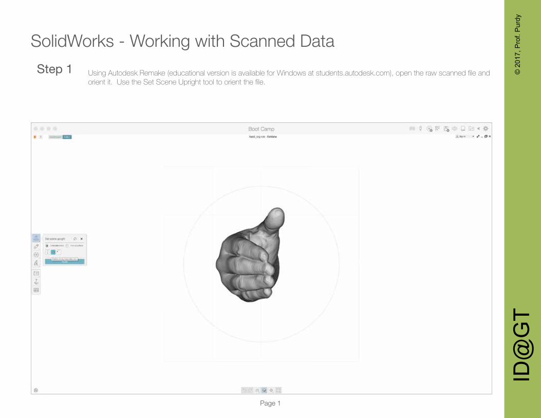
Using Autodesk Remake (educational version is available for Windows at students.autodesk.com), open the raw scanned file and orient it. Use the Set Scene Upright tool to orient the file.
Step 1
ID@
GT
© 2
017,
Pro
f. P
urdy
SolidWorks - Working with Scanned Data
Page 2
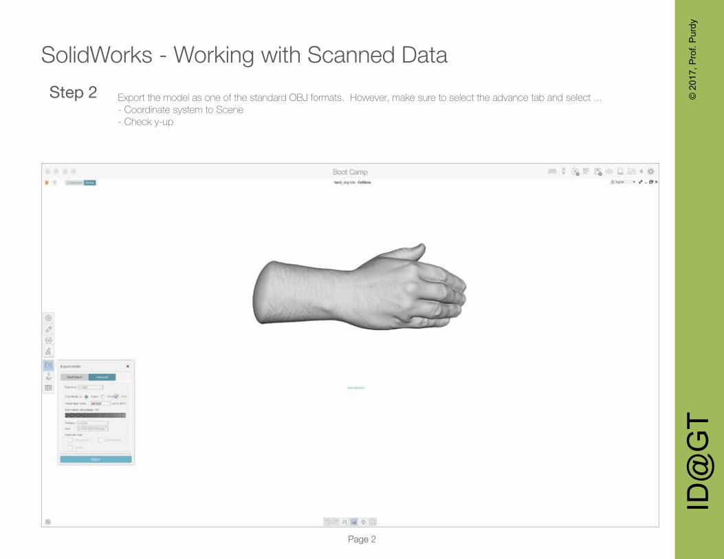
Export the model as one of the standard OBJ formats. However, make sure to select the advance tab and select ...- Coordinate system to Scene - Check y-up
Step 2
ID@
GT
© 2
017,
Pro
f. P
urdy
SolidWorks - Working with Scanned Data
Page 3
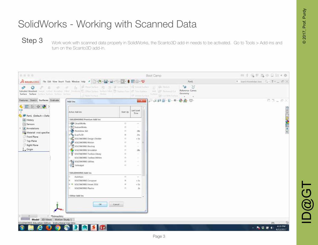
Work work with scanned data properly in SolidWorks, the Scanto3D add-in needs to be activated. Go to Tools > Add-ins and turn on the Scanto3D add-in.
Step 3
ID@
GT
© 2
017,
Pro
f. P
urdy
SolidWorks - Working with Scanned Data
Page 4
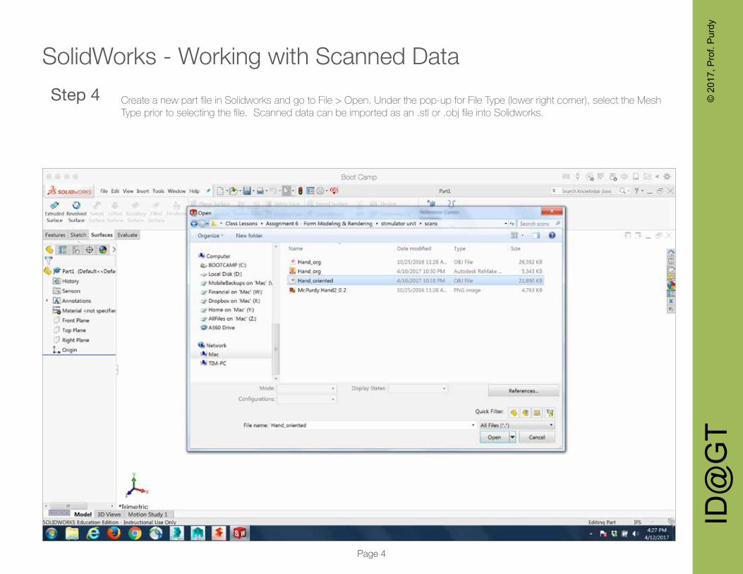
Create a new part file in Solidworks and go to File > Open. Under the pop-up for File Type (lower right corner), select the Mesh Type prior to selecting the file. Scanned data can be imported as an .stl or .obj file into Solidworks.
Step 4

ID@
GT
© 2
017,
Pro
f. P
urdy
SolidWorks - Working with Scanned Data
Page 5
Tools to work with scan data is located under the Tools > Scanto3D menu. Step 5
ID@
GT
© 2
017,
Pro
f. P
urdy
SolidWorks - Working with Scanned Data
Page 6
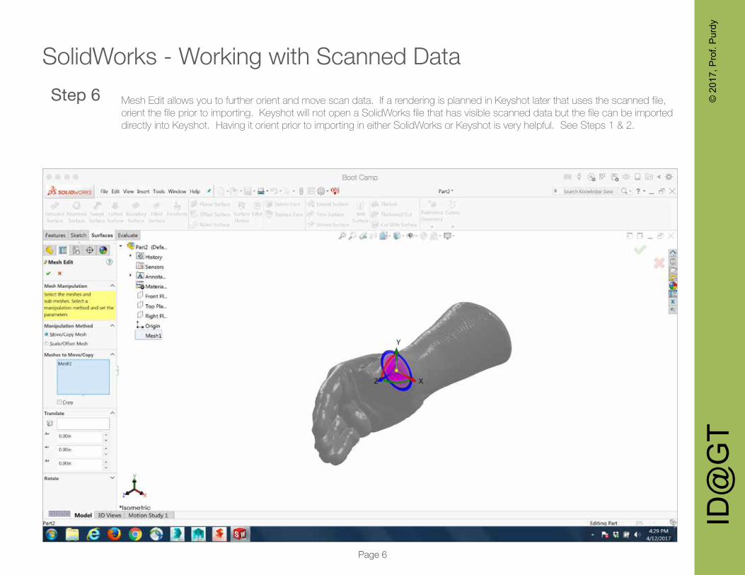
Mesh Edit allows you to further orient and move scan data. If a rendering is planned in Keyshot later that uses the scanned file, orient the file prior to importing. Keyshot will not open a SolidWorks file that has visible scanned data but the file can be imported directly into Keyshot. Having it orient prior to importing in either SolidWorks or Keyshot is very helpful. See Steps 1 & 2.
Step 6

ID@
GT
© 2
017,
Pro
f. P
urdy
SolidWorks - Working with Scanned Data
Page 7
To create a lofted surface that will closely follow the scanned data, first create the profile curves. Go to Tools > ScanTo3D > Curve Wizard. First set the Creation Mode to Section, then select the mesh. Next, pick the reference plan. It should be oriented perpendicular to the scanned data. Then select a point on the scanned data that indicates where to start the cross sections. Use the Reverse Direction button if the sections are not going in the right direction. Finally specify the distant and number of sec-
Step 7
ID@
GT
© 2
017,
Pro
f. P
urdy
SolidWorks - Working with Scanned Data
Page 8
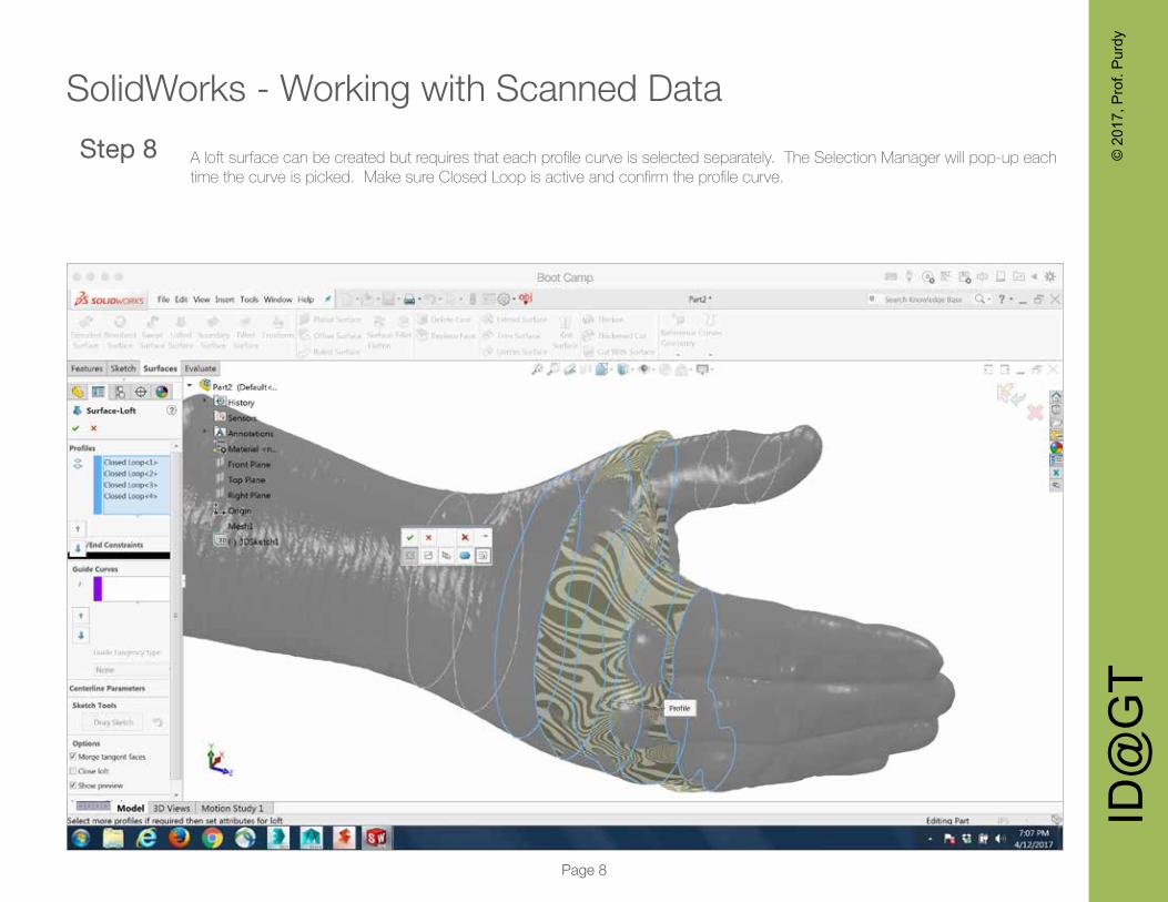
A loft surface can be created but requires that each profile curve is selected separately. The Selection Manager will pop-up each time the curve is picked. Make sure Closed Loop is active and confirm the profile curve.
Step 8
ID@
GT
© 2
017,
Pro
f. P
urdy
SolidWorks - Working with Scanned Data
Page 9
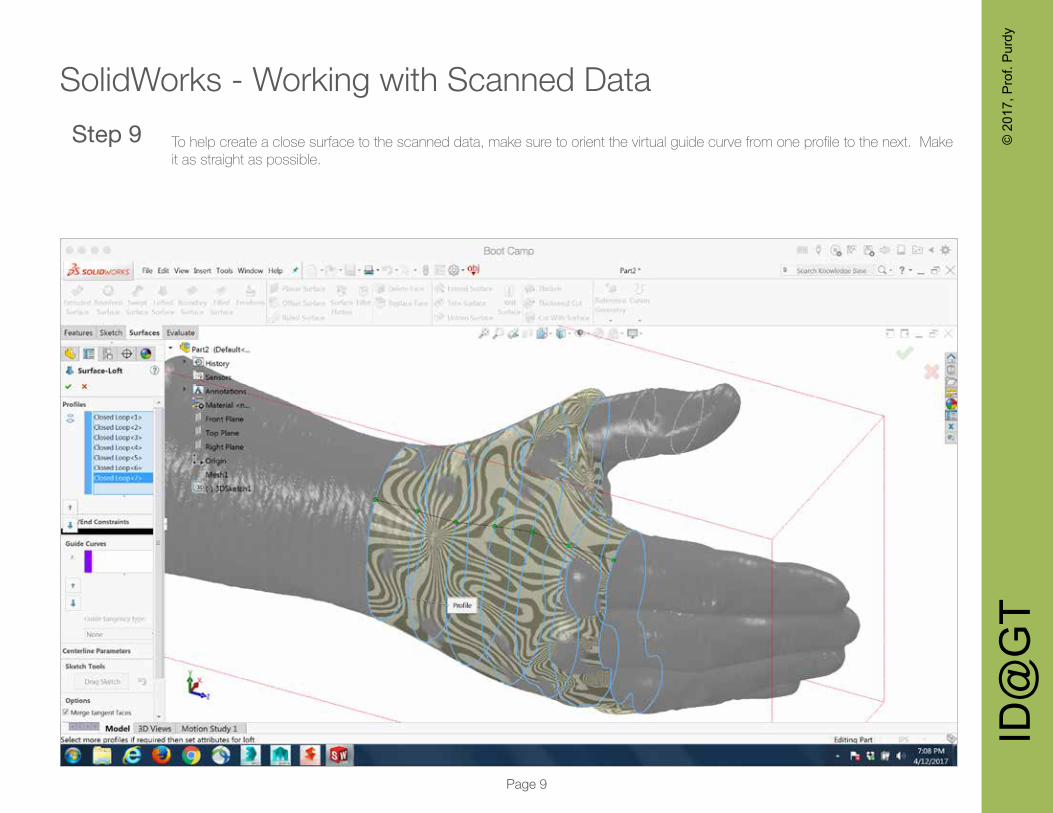
To help create a close surface to the scanned data, make sure to orient the virtual guide curve from one profile to the next. Make it as straight as possible.
Step 9

ID@
GT
© 2
017,
Pro
f. P
urdy
SolidWorks - Working with Scanned Data
Page 10
TO see how closely the loft surface fits the data, use the Tool > ScanTo3D > Deviation Analysis tool. The color code with show the deviation. Also, moving the mouse over the surface will the amount as well.
Step 10
ID@
GT
© 2
017,
Pro
f. P
urdy
SolidWorks - Working with Scanned Data
Page 11
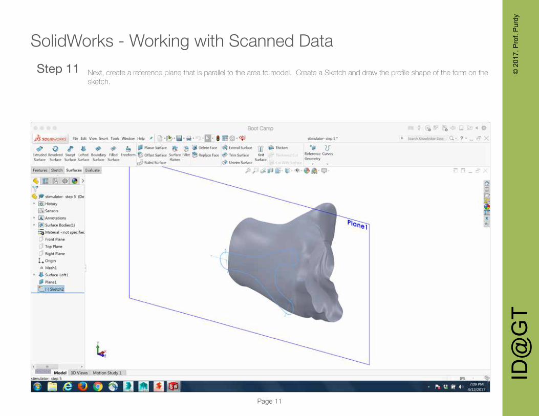
Next, create a reference plane that is parallel to the area to model. Create a Sketch and draw the profile shape of the form on the sketch.
Step 11
ID@
GT
© 2
017,
Pro
f. P
urdy
SolidWorks - Working with Scanned Data
Page 12
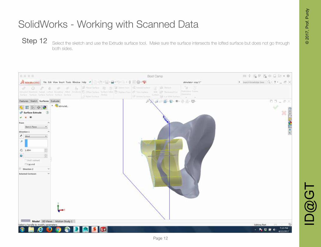
Select the sketch and use the Extrude surface tool. Make sure the surface intersects the lofted surface but does not go through both sides.
Step 12

ID@
GT
© 2
017,
Pro
f. P
urdy
SolidWorks - Working with Scanned Data
Page 13
Use the Trim tool in the Standard mode and select the area on the lofted surface to keep.Step 13

ID@
GT
© 2
017,
Pro
f. P
urdy
SolidWorks - Working with Scanned Data
Page 14
The Extrude surface should be hidden. The lofted surface follows the scanned data but is cut-out to the profile skect curve.Step 14
ID@
GT
© 2
017,
Pro
f. P
urdy
SolidWorks - Working with Scanned Data
Page 15
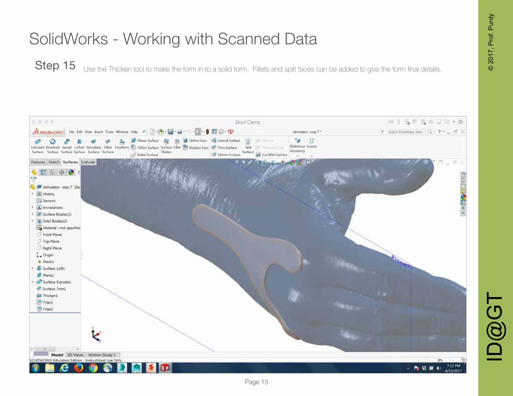
Use the Thicken tool to make the form in to a solid form. Fillets and split faces can be added to give the form final details.Step 15

ID@
GT
© 2
017,
Pro
f. P
urdy
SolidWorks - Working with Scanned Data
Page 16
Final detail was added to both sides of the form. Renderings where created using Keyshot and the reference scanned hand.