workcentre 423 xerox
TRANSCRIPT
Transmittal Page
3URGXFW
:RUN&HQWUH�3UR��������
7LWOH
6HUYLFH�0DQXDO
3DUW�1XPEHU
���3�����
6WDWXV
,QWLDO�,VVXH
'DWH
0DUFK�����

WorkCentre Pro423/4286HUYLFH�0DQXDO

WorkCentre Pro 423/428Service Manual
Issued: March 2002
● This service manual covers the followingmodels:
Electrostatic Copier manufacturedby FUJI XEROX Co., Ltd• WorkCentre Pro 423/428
● Related:•
● Confidentiality:
• This service manual is issued intendinguse by maintenance service personnelauthorized by Xerox. Copying,transferring or leasing this manualwithout prior consent by Xerox isprohibited.
• Whenever a page is superseded by areplacement page containing changesor modifications, remove and destroythe superseded page.
• Be careful of handling to avoid missingor damaging the manual.
● Revision and Modification Information:When design changes or revisions relatingto this service manual occur, the technicalinformation or service bulletin may be issuedas supplementary information until suchchanges have been accomodated in theupdated version of this service manual.
Important changes includingrevisions of spare part numbersand adjustment specificationsmust immediately be reflected onthe respective pages of thisservice manual upon reception ofsuch information.
Edited by: XEROX - GKLS[XEROX], [The Document Company] are registered trademarks
PRINTED IN GREAT BRITAIN
CAUTION
Revision Control ListProduct:
WorkCentre Pro 423/428
Title:
WorkService Manual
Part Number:
708P86749
Revision:
March 2002
'RFXPHQWDWLRQ�DYDLODEOH�
+DUG�&RS\ ���3�����3')�YHUVLRQ�RQ�&'�520 ���3�����
$OO�SDJHV�LQ�WKLV�PDQXDO�DUH�UHYLVLRQ������

INTRODUCTION
• Scope of this Document
• How to Use this Manual
• Terms and Symbols
• Abbreviations
• Safety Information
• Translation of Warnings
SECTION 1 SERVICE CALL PROCEDURES
SECTION 2 TROUBLESHOOTING
SECTION 3 IMAGE QUALITY TROUBLESHOOTING
SECTION 4 DISASSEMBLY/ASSEMBLY AND ADJUSTMENT
SECTION 5 PARTS LIST
SECTION 6 GENERAL PROCEDURES
SECTION 7 ELECTRICAL WIRING DIAGRAMS
SECTION 8 ACCESSORIES
SECTION 9 BSD (BLOCK SCHEMATIC DIAGRAM)


INTRODUCTION

03/02 ContentsWorkCentre 423/428 1 INTRODUCTION
Contents
1 Scope of this Document ...........................................................................2
2 How to Use this Manual ............................................................................2
2.1 Organisation of this Manual ...................................................................22.2 Revision Information ...............................................................................23 Terms and Symbols...................................................................................3
4 Abbreviations.............................................................................................4
5 Safety Information.....................................................................................5
6 Translation of Warnings............................................................................7
WorkCentre 423/428 03/02 INTRODUCTION2 1 Scope of this Document
1 Scope of this DocumentThis document is intended to serve as the standard service manual for the WorkCentrePro 423/428.
Publication Comment Sheet
If you have any comments, or wish to make any suggestions, please complete thePublication Comment Sheet (PCS) at the back of this manual.
2 How to Use this ManualThis manual covers the standard service procedures for the WorkCentre Pro 423/428.Follow the instructions in Section 1 Service Call Procedure when visiting customerlocations on service calls.
2.1 Organisation of this Manual
• HardwareThis manual summarises all technical information on the WorkCentre Pro 423/428.• Sections
This manual consists of nine Sections:
Section 1 - Service Call Procedure
This Section describes the general procedures and service practices to be utilised whenservicing the WorkCentre Pro 423/428.
Section 2 - Troubleshooting
This Section describes the troubleshooting procedures, except for image qualitytroubleshooting.
Section 3 - Image Quality Troubleshooting
This Section describes the image quality troubleshooting procedures.
Section 4 - Disassembly and Assembly Procedures, Adjustment
This Section describes procedures for the disassembly, assembly, adjustment, andreplacement of components.
Section 5 - Parts List
This Section contains lists of parts, spared and otherwise.
Section 6 - General
This Section provides the general information:
Section 7 - Electrical Wiring Diagrams
This Section provides the information related to electrical wiring:
Section 8 - Accessories
This Section provides information related to specific accessories & options.
Section 9 - BSD
This Section contains the BSD (Block Schematic Diagram) drawings.
2.2 Revision Information
Revisions for this manual will be promulgated as described below and associatedinformation will be sent to all customer engineers. This manual should be kept up-to-dateat all times by replacing superseded pages/old information with new pages/information.
Revision Procedure
• When the entire manual is revised, the publication number on the cover sheet willbe changed from Revision 1 to Revision 2, Revision 3, etc.
• When this manual is partially revised, revisions will be sequentially indicated asRevision A, Revision B, Revision C, etc. All revised pages will be markedaccordingly with “Revision A’, “Revision B”, “Revision C”, and so on.
Revision Sidebar
When any paragraph, table, or figure has been added or amended, a revision sidebar willbe added to indicate where the revision was made.
ExampleIf the same page is changed again due to a subsequent revision, revision sidebarsassociated with the previous revision(s) will be deleted.
03/02 3 Terms and SymbolsWorkCentre 423/428 3 INTRODUCTION
3 Terms and SymbolsSpecific terms and symbols used in any particular section are described in the Preface forthat section.The following terms and symbols are used throughout this manual:
Warnings, Cautions and Notes
• Translated versions of all warnings are in Translation of Warnings.• Une version localisée de toutes les notes Danger se trouve dans la section”Translation of
Warnings”.• Una versione tradotta di tutti questi avvisi si trova in Traduzione degli avvisi.• Eine Übersetzung aller Warnmeldungen wird mit dem Text “Übersetzung von
Warnhinweisen” geliefert.
• Hay una versión traducida de todos los avisos en la traducción de avisos.
WARNINGA warning is used whenever an operating or maintenance procedure, practice condition orstatement, if not strictly observed, could result in personal injury.
CAUTION
A caution is used whenever an operation or maintenance procedure, practice, condition orstatement, if not strictly observed, could result in damage to the equipment.
NOTE: A note is used where it is essential to highlight a procedure, practice, condition orstatement.
Used to alert you to a procedure which, if not strictly observed, couldresult in damage to the printer or equipment.
Used when work procedures and rules are emphasised.
Used when other explanations are given.
Used to explain the purpose of an adjustment.
REP: Indicates reference to the appropriate repair procedure.ADJ: Indicates reference to the appropriate adjustment procedure.PL: Indicates reference to the appropriate parts list.ASSY: Abbreviation of “Assembly”.
WARNINGDisconnect the power cord from the outlet while performing any tasks that do not need theelectricity on. Contact with electricity can cause death or injury. Contact with moving partscan cause serious injury.
WARNINGDo not work in a confined space. 1m (39 inches) is required to allow safe live working.Move the machine if necessary to achieve this.
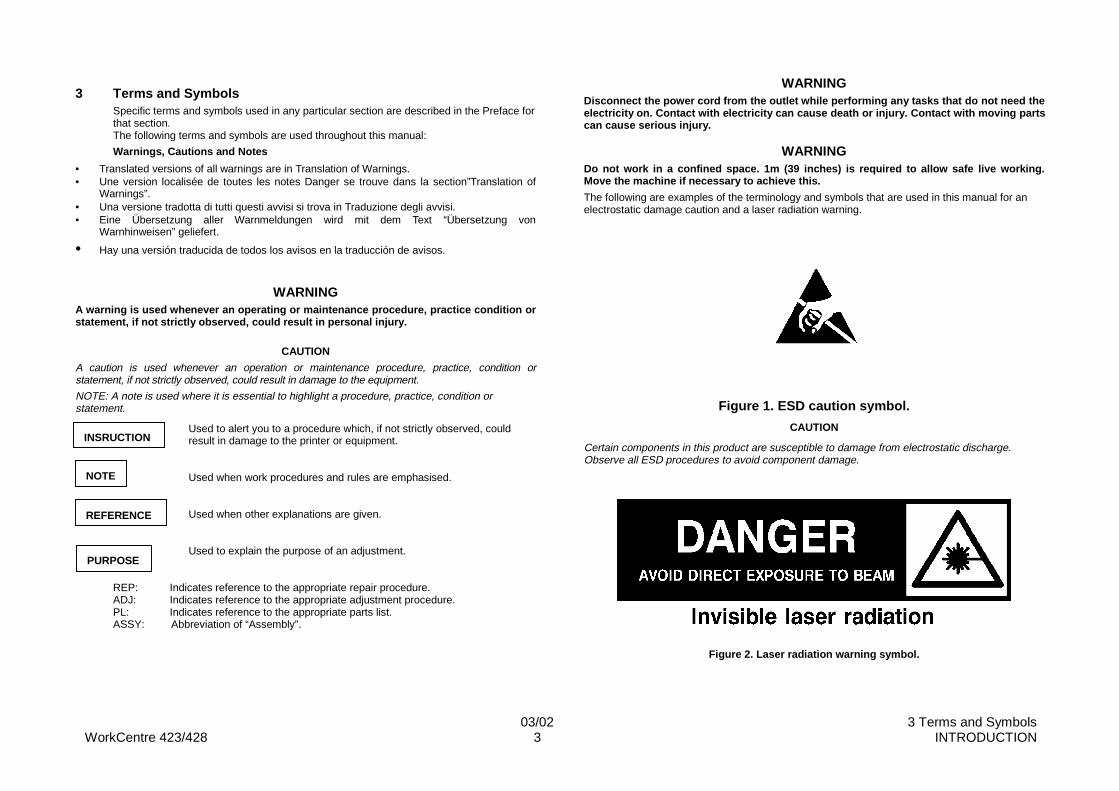
The following are examples of the terminology and symbols that are used in this manual for anelectrostatic damage caution and a laser radiation warning.
Figure 1. ESD caution symbol.
CAUTION
Certain components in this product are susceptible to damage from electrostatic discharge.Observe all ESD procedures to avoid component damage.
Figure 2. Laser radiation warning symbol.
INSRUCTION
NOTE
REFERENCE
PURPOSE
WorkCentre 423/428 03/02 INTRODUCTION4 4 Abbreviations
WARNINGUse of controls or adjustments or performance of procedures other than those specified inthis manual may result in hazardous radiation exposure. This machine is certified tocomply with laser product performance standards set by the US department of health andhuman services as a class 1 product. This means that it is a laser product that does notemit dangerous laser radiation during any mode of customer operation. During servicing,the laser beam could cause eye damage if looked at directly. The service proceduresmust be followed exactly as written without change.
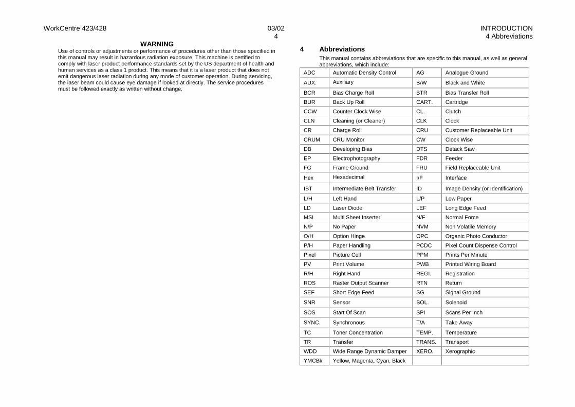
4 AbbreviationsThis manual contains abbreviations that are specific to this manual, as well as generalabbreviations, which include:
ADC Automatic Density Control AG Analogue Ground
AUX. Auxiliary B/W Black and White
BCR Bias Charge Roll BTR Bias Transfer Roll
BUR Back Up Roll CART. Cartridge
CCW Counter Clock Wise CL. Clutch
CLN Cleaning (or Cleaner) CLK Clock
CR Charge Roll CRU Customer Replaceable Unit
CRUM CRU Monitor CW Clock Wise
DB Developing Bias DTS Detack Saw
EP Electrophotography FDR Feeder
FG Frame Ground FRU Field Replaceable Unit
Hex Hexadecimal I/F Interface
IBT Intermediate Belt Transfer ID Image Density (or Identification)
L/H Left Hand L/P Low Paper
LD Laser Diode LEF Long Edge Feed
MSI Multi Sheet Inserter N/F Normal Force
N/P No Paper NVM Non Volatile Memory
O/H Option Hinge OPC Organic Photo Conductor
P/H Paper Handling PCDC Pixel Count Dispense Control
Pixel Picture Cell PPM Prints Per Minute
PV Print Volume PWB Printed Wiring Board
R/H Right Hand REGI. Registration
ROS Raster Output Scanner RTN Return
SEF Short Edge Feed SG Signal Ground
SNR Sensor SOL. Solenoid
SOS Start Of Scan SPI Scans Per Inch
SYNC. Synchronous T/A Take Away
TC Toner Concentration TEMP. Temperature
TR Transfer TRANS. Transport
WDD Wide Range Dynamic Damper XERO. Xerographic
YMCBk Yellow, Magenta, Cyan, Black
03/02 5 Safety InformationWorkCentre 423/428 5 INTRODUCTION
5 Safety Information
CAUTION
During normal operation, this machine produces ozone gas. The amount of ozone produced doesnot present a hazard to the operator. However, it is advisable that the machine be operated in a well-ventilated area.
NOTE: The product contains a dry imager cartridge that is recyclable. Under various states andlocal laws, it may be illegal to dispose of the cartridge into the municipal waste. Check with thelocal waste officials for details on recycling options or the proper disposal procedures.
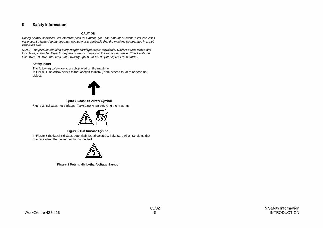
Safety Icons
The following safety icons are displayed on the machine:In Figure 1, an arrow points to the location to install, gain access to, or to release anobject.
Figure 1 Location Arrow Symbol
Figure 2, indicates hot surfaces. Take care when servicing the machine.
Figure 2 Hot Surface Symbol
In Figure 3 the label indicates potentially lethal voltages. Take care when servicing themachine when the power cord is connected.
Figure 3 Potentially Lethal Voltage Symbol
WorkCentre 423/428 03/02 INTRODUCTION6 6 Health and Safety Incident Reporting
6 Health and Safety Incident ReportingI. Summary
This standard defines requirements for notification of health and safety incidents involving Xeroxproducts (equipment and materials) at customer locations.
II. Scope
Xerox Corporation and subsidiaries world-wide.
III. Objective
To enable prompt resolution of health and safety incidents involving Xerox products and to ensureXerox regulatory compliance.
IV. Definitions
Incident:
An event or condition occurring in a customer account that has resulted in injury, illness orproperty damage. Examples of incidents include machine fires, smoke generation, physical injuryto an operator or service representative. Alleged events and product conditions are included inthis definition.
V. Requirements
Initial Report:
1. Xerox organisations shall establish a process for individuals to report product incidents toEH&S within 24 hours of becoming aware of the event.
2. The information to be provided at the time of reporting is contained in Appendix A (Healthand Safety Incident Report involving a Xerox product).
3. The initial notification may be made by any of the following methods:
• For incidents in North America and Developing Markets West (Brazil, Mexico, LatinAmerican North and Latin American South):
• Phone* EH&S at: 1-800-828-6571.
• Electronic mail EH&S at: [email protected].
• Fax EH&S at: 1-716-422-7734 [intelnet 8*222 7734].
• For incidents in Europe and Developing Markets East (Middle East, Africa, India,China and Hong Kong):
• Phone* EH&S at: +44 (0) 1707 35343.
• Electronic mail EH&S at: [email protected].
• Fax EH&S at: +44 (0) 1707 353914 [intelnet 8*668 3914].
*Initial notification made by phone must be followed within 24 hours by a completedincident report and sent to the indicated electronic mail address or fax number.
NOTE: If sending a fax, please also send the original via internal mail.
Responsibilities for resolution:
1. Business Groups/Product Design Teams responsible for the product involved in the incidentshall:
a) Manage field bulletins, customer correspondence, product recalls, safety retrofits.
b) Fund all field retrofits.
2. Field Service Operations shall:
c) Preserve the Xerox product involved and the scene of the incident inclusive of anyassociated equipment located in the vicinity of the incident.
d) Return any affected equipment/part(s) to the location designated by EH&S and/or theBusiness Division.
e) Implement all safety retrofits.
3. EH&S shall:
f) Manage and report all incident investigation activities.
g) Review and approve proposed product corrective actions and retrofits, if necessary.
h) Manage all communications and correspondence with government agencies.
i) Define actions to correct confirmed incidents.
VI. Appendices
The Health and Safety Incident Report involving a Xerox Product (Form # EH&S-700) is availableat the end of this Service Manual.
03/02 7 Translation of WarningsWorkCentre 423/428 7 INTRODUCTION
7 Translation of WarningsChapter 1 - Service Call Procedures.
WARNINGA warning is used whenever an operating or maintenance procedure, practice condition orstatement, if not strictly observed, could result in personal injury.
DANGERUne note Danger est utilisée chaque fois qu’une procédure d’utilisation ou demaintenance, une pratique, condition ou proposition peut provoquer des blessures si ellen’est pas strictement respectée.
ATTENZIONEUn avviso come questo viene usato ogni qualvolta la mancata osservanza di unaprocedura di funzionamento o manutenzione, di una certa condizione o avvertimentopotrebbe provocare ferite personali.
VORSICHTWarnhinweise dieser Art gelten für Anweisungen und Situationen (im Normalbetrieb oderbei der Wartung), bei deren Nichtbeachtung oder Auftreten Verletzungsgefahr besteht.
AVISOSe usa un aviso siempre que se observa un procedimiento de funcionamiento omantenimiento, condición o declaración de práctica, que pueden ocasionar dañospersonales si no se respetan estrictamente.
WARNINGSwitch off the power to the machine and disconnect the power cord from the outlet whileperforming any tasks that do not need the electricity on. Contact with electricity can causedeath or injury. Contact with moving parts can cause serious injury.
DANGERCouper l’alimentation de la machine et débrancher le cordon de la prise pour effectuertoute tâche qui ne requiert pas de tension électrique. L’électricité peut causer desblessures ou la mort. Les pièces en mouvement peuvent provoquer de graves blessures.
ATTENZIONESpegnere la macchina e staccare il cavo di alimentazione dalla presa durante l’esecuzionedelle operazioni che non richiedono che la macchina sia collegata alla corrente elettrica.L’eventuale contatto con l’elettricità può provocare la morte o ferite gravi. L’eventualecontatto con parti in movimento può provocare ferite gravi.
VORSICHTBei Arbeiten, bei denen kein Strom erforderlich ist, das Gerät ausschalten und denNetzstecker abziehen. Beim Umgang mit elektrischen Geräten ist äußerste Vorsicht
geboten, da dies zu ernsthaften Verletzungen oder Stromschlägen führen kann. DerUmgang mit beweglichen Bauteilen kann zu ernsthaften körperlichen Verletzungen führen.
AVISOApague la máquina y desconecte el cable de potencia de la red antes de realizar tareasque no requieran el uso de electricidad. El contacto con la corriente eléctrica puedeocasionar muerte o heridas. El contacto con piezas en movimiento puede ocasionar seriosdaños.
WARNINGDo not work in a confined space. 1m (39 inches) is required to allow safe live working.Move the machine if necessary to achieve this.
DANGERNe pas travailler dans un espace limité. Un espace libre de 1m (39 pouces) est requis pourpermettre l’intervention en toute sécurité. Déplacer la machine si nécessaire pour assurerl’espace minimum.
ATTENZIONENon lavorare in uno spazio ristretto. È necessario almeno un metro per la sicurezza dellavoro. Se necessario, spostare la macchina per ottenere questo.
VORSICHTFür ausreichend Platz beim Arbeiten sorgen. Um ein sicheres Arbeiten zu gewährleisten,wird ein Arbeitsbereich von 1m (39 Zoll) vorgeschrieben. Im Notfall das Gerätentsprechend umstellen.
AVISONo trabaje en un espacio limitado. Se requiere 1m (39 pulgadas) para que pueda trabajarsin peligro. Si es necesario, mueva la máquina para lograr esto.
WARNINGUse of controls or adjustments or performance of procedures other than those specified inthis manual may result in hazardous radiation exposure. This machine is certified tocomply with laser product performance standards set by the US department of health andhuman services as a class 1 product. This means that it is a laser product that does notemit dangerous laser radiation during any mode of customer operation. During servicing,the laser beam could cause eye damage if looked at directly. The service procedures mustbe followed exactly as written without change.
DANGERL’exécution de procédures ou l’utilisation de commandes ou de réglages autres que ceuxspécifiés dans cette publication peut entraîner une exposition dangereuse aux rayonslaser. Cette machine est certifiée conforme aux normes définies par les organismesgouvernementaux des États-Unis pour les produits laser de classe 1. Elle n’émet pas derayonnement dangereux pendant le fonctionnement en mode client. Au cours desinterventions, le faisceau laser peut causer de graves lésions aux yeux s’il est regardé
WorkCentre 423/428 03/02 INTRODUCTION8 7 Translation of Warnings
directement. Les procédures d’entretien doivent être rigoureusement suivies commeindiqué dans la documentation.
ATTENZIONEL’uso di controlli o regolazioni o procedure diverse da quelle indicate in questo manualepossono provocare esposizione a radiazioni pericolose. Questa macchina, classificatacome un prodotto di classe 1 relativamente all’emissione di raggi laser, è certificataconforme agli standard fissati dall’US department of health and human services (Ministerodella Sanità USA). Ciò significa che questo prodotto non emette raggi laser pericolosidurante il suo normale funzionamento. Durante la manutenzione, il raggio laser potrebbeprovocare danni alla vista se osservato direttamente. Le procedure di servizio devonoessere strettamente osservate, senza alcuna deviazione.
VORSICHTDas nicht den Vorschriften entsprechende Bedienen des Geräts, Ausführen vonWartungsarbeiten oder Ändern bestimmter Geräteeinstellungen kann zum Kontakt mitgefährlicher Laserstrahlung führen. Dieses Gerät wird als Gerät der Laserklasse 1 (CDRHGeräteklasse 1, IEC 825 Klasse 1) eingestuft. Produkte dieser Klasse geben imNormalbetrieb keine gefährliche Laserstrahlung ab. Bei Wartungsarbeiten kann die direkteAnsicht der Laserstrahlung zu ernsthaften Langzeitschäden der Augen führen. AlleWartungsarbeiten müssen unbedingt den Vorschriften entsprechend ausgeführt werden.
AVISOEl uso de controles o de ajustes, o la realización de procedimientos que no sean aquellosespecificados en este manual, puede resultar en exposición peligrosa a la radiación. Estamáquina ha sido certificada y cumple con los estándares de funcionamiento de losproductos láser, establecidos por el Departamento de Salud y Servicios Humanos de losEstado Unidos, como un producto de la Clase 1. Esto significa que es un producto láserque no emite radiación láser peligrosa durante ninguno de sus modos de funcionamientodel operador. Durante el servicio, el rayo láser podría ocasionar daños a la vista si seobserva directamente. Los procedimientos de servicio deben seguirse exactamente comoestán escritos, sin ningún cambio.
Chapter 2 – Troubleshooting.
WARNINGSwitch off the machine and disconnect the power cord.
DANGERIsoler la machine et débrancher le cordon d’alimentation.
ATTENZIONESpegnere la macchina e staccare il cavo di alimentazione.
VORSICHTDas Gerät ausschalten und den Netzstecker aus der Stromquelle entfernen.
AVISOApague la máquina y desconecte el cable de potencia.
WARNINGSwitch off the power to the machine and disconnect the power cord from the outlet whileperforming any tasks that do not need the electricity on. Contact with electricity can causedeath or injury.
DANGERCouper l’alimentation de la machine et débrancher le cordon de la prise pour effectuertoute tâche qui ne requiert pas de tension électrique. L’électricité peut causer desblessures ou la mort.
ATTENZIONESpegnere la macchina e staccare il cavo di alimentazione dalla presa durante l’esecuzionedelle operazioni che non richiedono che la macchina sia collegata alla corrente elettrica.L’eventuale contatto con l’elettricità può provocare la morte o ferite gravi.
VORSICHTBei Arbeiten, bei denen kein Strom erforderlich ist, das Gerät ausschalten und denNetzstecker abziehen. Beim Umgang mit elektrischen Geräten ist äußerste Vorsichtgeboten, da dies zu ernsthaften Verletzungen oder Stromschlägen führen kann.
AVISOApague la máquina y desconecte el cable de potencia de la red antes de realizar tareasque no requieran el uso de electricidad. El contacto con la corriente eléctrica puedeocasionar muerte o daños.
WARNING

03/02 7 Translation of WarningsWorkCentre 423/428 9 INTRODUCTION
Follow the service procedure exactly as written. Use of controls or adjustments other thanthose specified in this manual, may result in an exposure to invisible laser radiation.During servicing, the invisible laser radiation can cause eye damage if looked at directly.
DANGERLes procédures d’entretien doivent être rigoureusement suivies comme indiqué dans ladocumentation. L’utilisation de commandes ou de réglages autres que ceux spécifiésdans cette publication peut entraîner une exposition aux rayons laser invisibles. Au coursdes interventions, le faisceau laser invisible peut causer de graves lésions aux yeux s’ilest regardé directement.
ATTENZIONEOsservare strettamente le procedure di servizio. L’uso di controlli o regolazioni oprocedure diverse da quelle indicate in questo manuale possono provocare esposizione aradiazioni laser invisibili. Durante la manutenzione, il raggio laser potrebbe provocaredanni alla vista se osservato direttamente.
VORSICHTAlle Wartungsmaßnahmen den Vorschriften entsprechend ausführen. Das nicht denVorschriften entsprechende Bedienen der Geräts oder Ändern bestimmterGeräteeinstellungen kann zum Kontakt mit (unsichtbarer) Laserstrahlung führen.(Unsichtbare) Laserstrahlung kann beim direkter Ansicht zu ernsthaften Langzeitschädender Augen führen.
AVISOSiga el procedimiento de servicio exactamente como se describe. El uso de controles oajustes que no sean aquellos especificados en este manual puede resultar en exposición aradiación invisible de láser. Durante el servicio, la radiación invisible de láser puedeocasionar daños a la vista, si se mira directamente.
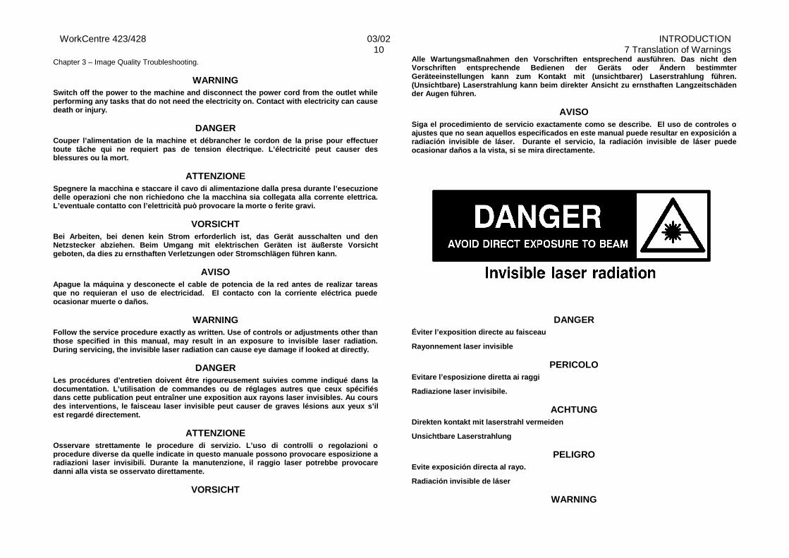
DANGER
Éviter l’exposition directe au faisceau
Rayonnement laser invisible
PERICOLOEvitare l’esposizione diretta ai raggi
Radiazione laser invisibile.
ACHTUNGDirekten kontakt mit laserstrahl vermeiden
Unsichtbare Laserstrahlung
PELIGROEvite exposición directa al rayo.
Radiación invisible de láser
WARNINGSwitch off the machine and disconnect the power cord.
DANGERIsoler la machine et débrancher le cordon d’alimentation.
ATTENZIONESpegnere la macchina e staccare il cavo di alimentazione.
VORSICHTDas Gerät ausschalten und den Netzstecker aus der Stromquelle entfernen.
AVISOApague la máquina y desconecte el cable de potencia.
WorkCentre 423/428 03/02 INTRODUCTION10 7 Translation of Warnings
Chapter 3 – Image Quality Troubleshooting.
WARNINGSwitch off the power to the machine and disconnect the power cord from the outlet whileperforming any tasks that do not need the electricity on. Contact with electricity can causedeath or injury.
DANGERCouper l’alimentation de la machine et débrancher le cordon de la prise pour effectuertoute tâche qui ne requiert pas de tension électrique. L’électricité peut causer desblessures ou la mort.
ATTENZIONESpegnere la macchina e staccare il cavo di alimentazione dalla presa durante l’esecuzionedelle operazioni che non richiedono che la macchina sia collegata alla corrente elettrica.L’eventuale contatto con l’elettricità può provocare la morte o ferite gravi.
VORSICHTBei Arbeiten, bei denen kein Strom erforderlich ist, das Gerät ausschalten und denNetzstecker abziehen. Beim Umgang mit elektrischen Geräten ist äußerste Vorsichtgeboten, da dies zu ernsthaften Verletzungen oder Stromschlägen führen kann.
AVISOApague la máquina y desconecte el cable de potencia de la red antes de realizar tareasque no requieran el uso de electricidad. El contacto con la corriente eléctrica puedeocasionar muerte o daños.
WARNINGFollow the service procedure exactly as written. Use of controls or adjustments other thanthose specified in this manual, may result in an exposure to invisible laser radiation.During servicing, the invisible laser radiation can cause eye damage if looked at directly.
DANGERLes procédures d’entretien doivent être rigoureusement suivies comme indiqué dans ladocumentation. L’utilisation de commandes ou de réglages autres que ceux spécifiésdans cette publication peut entraîner une exposition aux rayons laser invisibles. Au coursdes interventions, le faisceau laser invisible peut causer de graves lésions aux yeux s’ilest regardé directement.
ATTENZIONEOsservare strettamente le procedure di servizio. L’uso di controlli o regolazioni oprocedure diverse da quelle indicate in questo manuale possono provocare esposizione aradiazioni laser invisibili. Durante la manutenzione, il raggio laser potrebbe provocaredanni alla vista se osservato direttamente.
VORSICHT
Alle Wartungsmaßnahmen den Vorschriften entsprechend ausführen. Das nicht denVorschriften entsprechende Bedienen der Geräts oder Ändern bestimmterGeräteeinstellungen kann zum Kontakt mit (unsichtbarer) Laserstrahlung führen.(Unsichtbare) Laserstrahlung kann beim direkter Ansicht zu ernsthaften Langzeitschädender Augen führen.
AVISOSiga el procedimiento de servicio exactamente como se describe. El uso de controles oajustes que no sean aquellos especificados en este manual puede resultar en exposición aradiación invisible de láser. Durante el servicio, la radiación invisible de láser puedeocasionar daños a la vista, si se mira directamente.
DANGERÉviter l’exposition directe au faisceau
Rayonnement laser invisible
PERICOLOEvitare l’esposizione diretta ai raggi
Radiazione laser invisibile.
ACHTUNGDirekten kontakt mit laserstrahl vermeiden
Unsichtbare Laserstrahlung
PELIGROEvite exposición directa al rayo.
Radiación invisible de láser
WARNING
03/02 7 Translation of WarningsWorkCentre 423/428 11 INTRODUCTION
Some of the Image Quality correction activities can involve exposure to laser radiation.This is indicated by the laser warning symbol in the text. Where this is seen, observe thelaser precautions.
DANGERCertaines activités correctives de qualité image peuvent entraîner une exposition auxrayons laser. Chaque fois que le symbole de sécurité laser apparaît dans le texte, prendreles précautions nécessaires.
ATTENZIONEAlcune attività di correzione della qualità immagine possono comportare l’esposizione araggi laser. Questa situazione è indicata nel testo dall’apposito simbolo di pericolo laser.In presenza di tale simbolo, osservare le specifiche relative precauzioni.
VORSICHTEinige Maßnahmen zur Verbesserung der Bildqualität können u.U. zum Kontakt mitLaserstrahlung führen. Auf diese Gefahrenquelle wird mit dem Symbol ACHTUNGLaserstrahlung hingewiesen. Nach Auffinden einer solchen Gefahrenquelle unbedingt alleLasersicherheitsregeln befolgen.
AVISOAlgunas de las actividades de corrección de calidad de imagen pueden incluir exposicióna la radiación del láser. Esto es indicado en el texto por medio del símbolo de aviso deláser. Siga las precauciones contra el láser cuando vea este símbolo.
Chapter 4 – Dissasembly and Assembly Procedures, Adjustments.
WARNINGSwitch off the machine and disconnect the power cord.
DANGERIsoler la machine et débrancher le cordon d’alimentation.
ATTENZIONESpegnere la macchina e staccare il cavo di alimentazione.
VORSICHTDas Gerät ausschalten und den Netzstecker aus der Stromquelle entfernen.
AVISOApague la máquina y desconecte el cable de potencia.
WARNINGAfter switching off the machine the fuser surfaces are still hot. Allow to cool, or avoidcontact while working near the fuser.
DANGERAprès coupure de l’alimentation de la machine, les surfaces du four sont toujourschaudes. Les laisser refroidir, ou éviter de toucher les surfaces en travaillant près du four.
ATTENZIONEDopo aver spento la macchina, le superfici del fusore sono ancora calde. Attendere che siraffreddino o evitare di toccarle mentre si lavora nell’area del fusore.
VORSICHTDie Fixieranlage erst nach ausreichender Abkühlzeit handhaben oder genügendSicherheitsabstand zu der noch heißen Fixieranlage bewahren.
AVISOLas superficies del fusor estarán calientes aun despues de haber apagado la máquina.Permita que se enfrien o evite el contacto cuando trabaje cerca de la superficie del fusor.
WARNINGThe weight of the DADF assembly is 8.6 kg (18.6 lb). Use great care when lifting.
DANGERLe chargeur de documents pèse 8,6 kg (18,6 lb). Faire très attention en le soulevant.
ATTENZIONE
WorkCentre 423/428 03/02 INTRODUCTION12 7 Translation of Warnings
Il complessivo DADF pesa 8,6 Kg. Fare molta attenzione quando lo si solleva.
VORSICHTDas Gewicht des Duplex-Vorlageneinzugs (DVE) beträgt 8,6 kg (18,6 Pfund). Vorsicht beimAnheben.
AVISOEl peso del conjunto del ADOD es de 8.6 kg (18.6 lb). Tenga mucho cuidado al levantarlo.
WARNINGThe weight of the Finisher assembly is 16 kg (35.3 lb). Use great care when lifting.
DANGERLe module de finition pèse 16 kg (35,3 lb). Faire très attention en le soulevant.
ATTENZIONEIl complessivo finitore pesa 16 Kg. Fare molta attenzione quando lo si solleva.
VORSICHTDas Gewicht der Finisher-Anlage beträgt 16 kg (35,3 Pfund). Vorsicht beim Anheben.
AVISOEl peso del conjunto de la acabadora es de 16 kg (35.3 lb). Tenga mucho cuidado allevantarla.
Chapter 6 - General
WARNINGThe weight of the IOT assembly is 46 kg (101 lb). Two persons will be required to lift thisassembly. Use great care when lifting.
DANGERL’IOT pèse 46 kg (101 lb). Deux personnes sont requises pour soulever ce module. Fairetrès attention en le soulevant.
ATTENZIONEIl complessivo IOT pesa 46 Kg. Sono necessarie due persone per alzarlo. Fare moltaattenzione quando lo si solleva.
VORSICHTDas Gewicht der IOT-Anlage beträgt 46 kg (101 Pfund). Vorsicht beim Anheben.
AVISOEl peso del conjunto IOT es de 46 kg (101 lb). Se requieren dos personas para levantareste conjunto. Tenga mucho cuidado al levantarlo.
WARNINGThe weight of the IIT assembly is 24 kg (53 lb). Two persons will be required to lift thisassembly. Use great care when lifting.
DANGERL’IIT pèse 24 kg (53 lb). Deux personnes sont requises pour soulever ce module. Faire trèsattention en le soulevant.
ATTENZIONEIl complessivo IIT pesa 24 Kg. Sono necessarie due persone per alzarlo. Fare moltaattenzione quando lo si solleva.
VORSICHTDas Gewicht der IIT-Anlage beträgt 24 kg (53 Pfund). Zum Anheben dieser Anlage sindmindestens zwei Personen erforderlich. Vorsicht beim Anheben.
AVISOEl peso del conjunto IIT (Terminal de entrada de imagen) es de 24 kg (53 lb). Se requierendos personas para levantar este conjunto. Tenga mucho cuidado al levantarlo.

03/02 7 Translation of WarningsWorkCentre 423/428 13 INTRODUCTION
Chapter 8 – Accessories
WARNINGSwitch off the machine and disconnect the power cord.
DANGERIsoler la machine et débrancher le cordon d’alimentation.
ATTENZIONESpegnere la macchina e staccare il cavo di alimentazione.
VORSICHTDas Gerät ausschalten und den Netzstecker aus der Stromquelle entfernen.
AVISOApague la máquina y desconecte el cable de potencia.
WARNINGThe weight of the DADF assembly is 8.6 kg (18.6 lb). Use great care when lifting.
DANGERLe chargeur de documents pèse 8,6 kg (18,6 lb). Faire très attention en le soulevant.
ATTENZIONEIl complessivo DADF pesa 8,6 Kg. Fare molta attenzione quando lo si solleva.
VORSICHTDas Gewicht des Duplex-Vorlageneinzugs (DVE) beträgt 8,6 kg (18,6 Pfund). Vorsicht beimAnheben.
AVISOEl peso del conjunto del ADOD es de 8.6 kg (18.6 lb). Tenga mucho cuidado al levantarlo.

WorkCentre 423/428 03/02 INTRODUCTION14 7 Translation of Warnings
CHAPTER 1 SERVICE CALL PROCEDURE

03/02 ContentsWorkCentre Pro 423/428 1-1 CHAPTER 1 SERVICE CALL PROCEDURE
Contents
1.1 Trimming..................................................................................................... 3
1.1.1 Trimming Procedure.................................................................................. 3
1.1.2 Consumables and consumable parts ........................................................ 3
1.1.3 Trimming Check List ................................................................................. 4

WorkCentre Pro 423/428 1-2 CHAPTER 1 SERVICE CALL PROCEDURE03/02 1.1 Trimming
03/02 1.1 TrimmingWorkCentre 423/428 1-3 CHAPTER 1 SERVICE CALL PROCEDURE
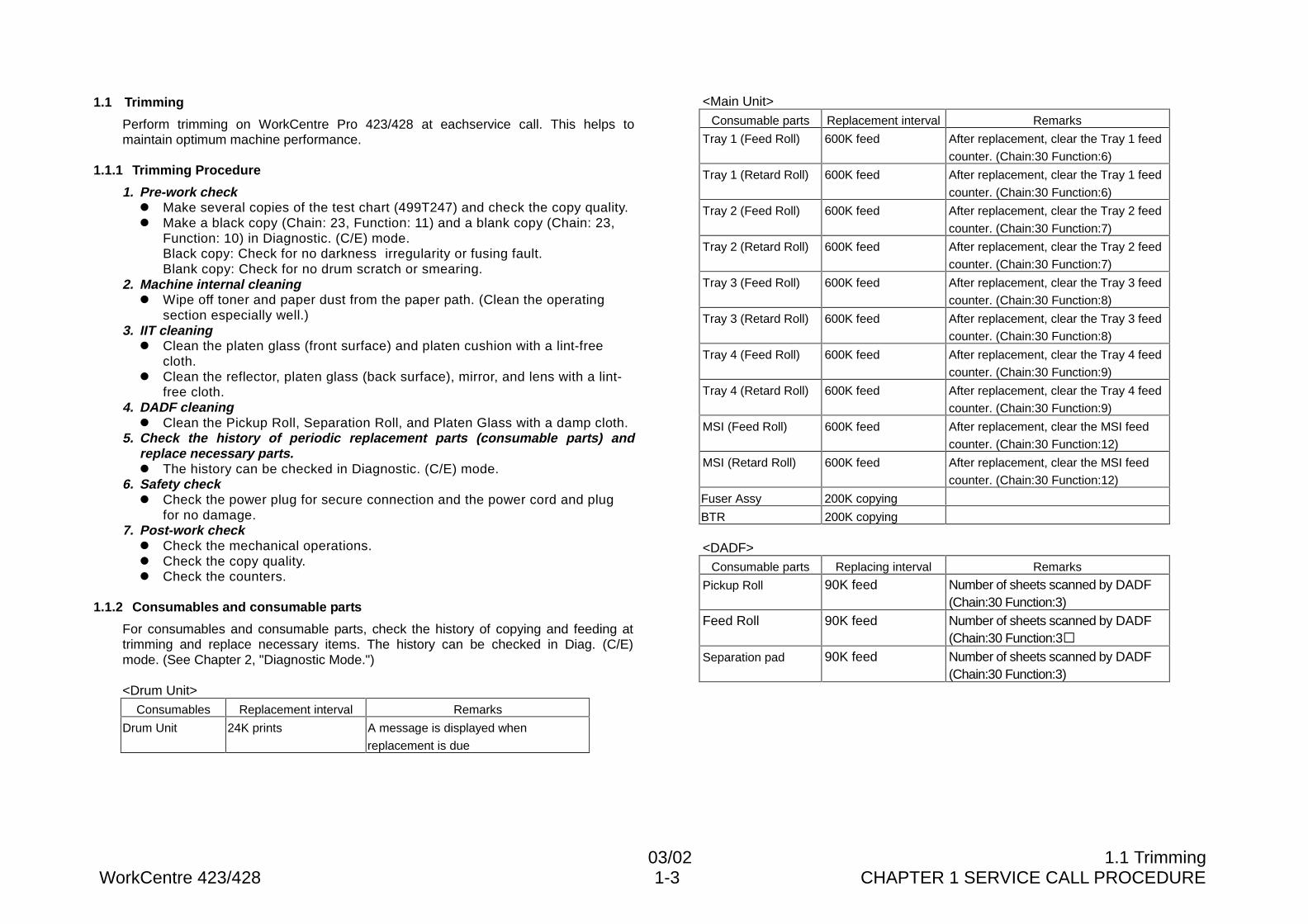
1.1 Trimming
Perform trimming on WorkCentre Pro 423/428 at eachservice call. This helps tomaintain optimum machine performance.
1.1.1 Trimming Procedure
1. Pre-work checkl Make several copies of the test chart (499T247) and check the copy quality.l Make a black copy (Chain: 23, Function: 11) and a blank copy (Chain: 23,
Function: 10) in Diagnostic. (C/E) mode.Black copy: Check for no darkness�irregularity or fusing fault.Blank copy: Check for no drum scratch or smearing.
2. Machine internal cleaningl Wipe off toner and paper dust from the paper path. (Clean the operating
section especially well.)3. IIT cleaning
l Clean the platen glass (front surface) and platen cushion with a lint-freecloth.
l Clean the reflector, platen glass (back surface), mirror, and lens with a lint-free cloth.
4. DADF cleaningl Clean the Pickup Roll, Separation Roll, and Platen Glass with a damp cloth.
5. Check the history of periodic replacement parts (consumable parts) andreplace necessary parts.l The history can be checked in Diagnostic. (C/E) mode.
6. Safety checkl Check the power plug for secure connection and the power cord and plug
for no damage.7. Post-work check
l Check the mechanical operations.l Check the copy quality.l Check the counters.
1.1.2 Consumables and consumable parts
For consumables and consumable parts, check the history of copying and feeding attrimming and replace necessary items. The history can be checked in Diag. (C/E)mode. (See Chapter 2, "Diagnostic Mode.")
<Drum Unit>Consumables Replacement interval Remarks
Drum Unit 24K prints A message is displayed when
replacement is due
<Main Unit>Consumable parts Replacement interval Remarks
Tray 1 (Feed Roll) 600K feed After replacement, clear the Tray 1 feed
counter. (Chain:30 Function:6)
Tray 1 (Retard Roll) 600K feed After replacement, clear the Tray 1 feed
counter. (Chain:30 Function:6)
Tray 2 (Feed Roll) 600K feed After replacement, clear the Tray 2 feed
counter. (Chain:30 Function:7)
Tray 2 (Retard Roll) 600K feed After replacement, clear the Tray 2 feed
counter. (Chain:30 Function:7)
Tray 3 (Feed Roll) 600K feed After replacement, clear the Tray 3 feed
counter. (Chain:30 Function:8)
Tray 3 (Retard Roll) 600K feed After replacement, clear the Tray 3 feed
counter. (Chain:30 Function:8)
Tray 4 (Feed Roll) 600K feed After replacement, clear the Tray 4 feed
counter. (Chain:30 Function:9)
Tray 4 (Retard Roll) 600K feed After replacement, clear the Tray 4 feed
counter. (Chain:30 Function:9)
MSI (Feed Roll) 600K feed After replacement, clear the MSI feed
counter. (Chain:30 Function:12)
MSI (Retard Roll) 600K feed After replacement, clear the MSI feed
counter. (Chain:30 Function:12)
Fuser Assy 200K copying
BTR 200K copying
<DADF>Consumable parts Replacing interval Remarks
Pickup Roll 90K feed Number of sheets scanned by DADF(Chain:30 Function:3)
Feed Roll 90K feed Number of sheets scanned by DADF(Chain:30 Function:3�
Separation pad 90K feed Number of sheets scanned by DADF(Chain:30 Function:3)
WorkCentre Pro 423/428 1-4 CHAPTER 1 SERVICE CALL PROCEDURE03/02 1.1 Trimming
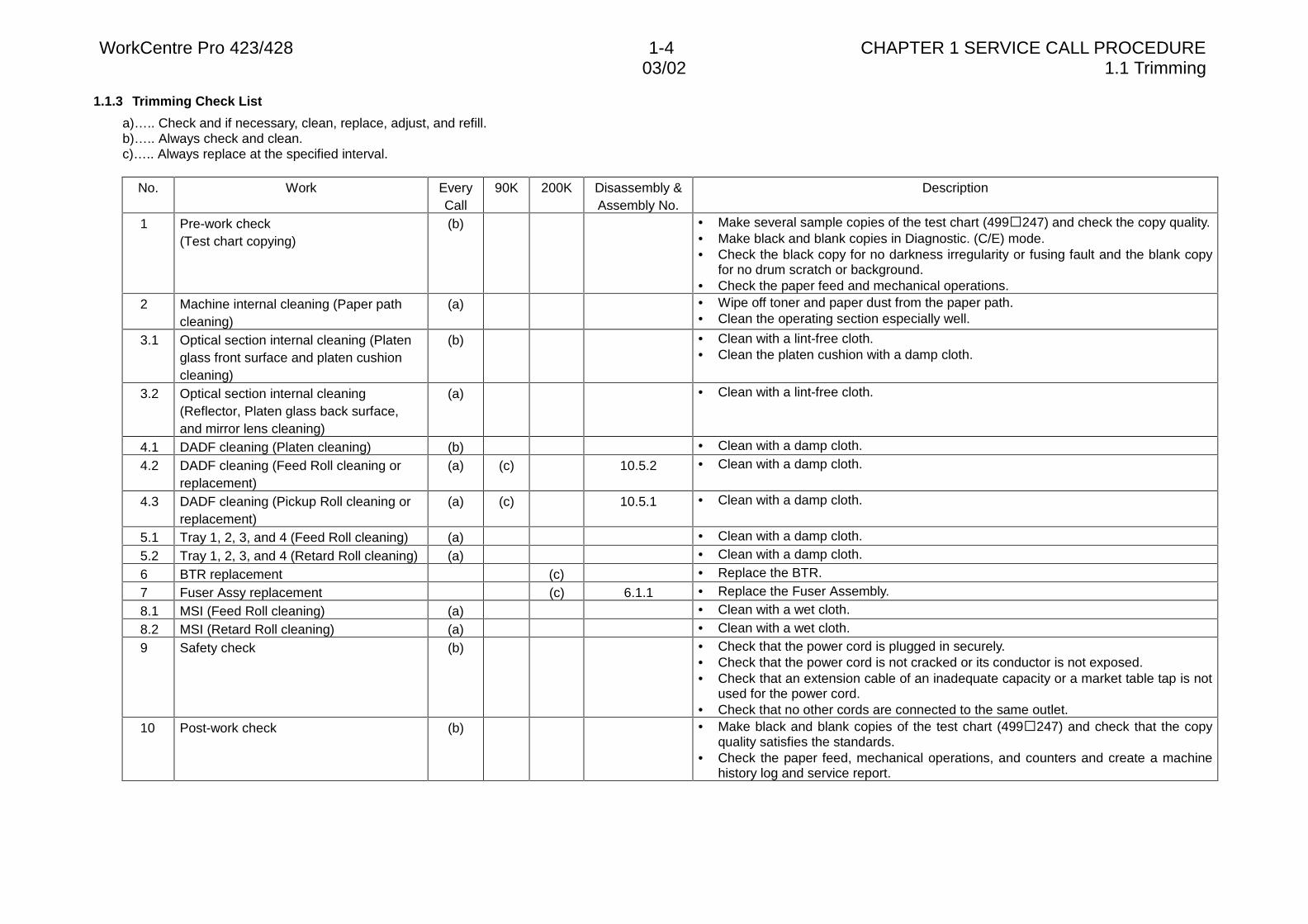
1.1.3 Trimming Check List
a)….. Check and if necessary, clean, replace, adjust, and refill.b)….. Always check and clean.c)….. Always replace at the specified interval.
No. Work EveryCall
90K 200K Disassembly &Assembly No.
Description
1 Pre-work check(Test chart copying)
(b) • Make several sample copies of the test chart (499�247) and check the copy quality.• Make black and blank copies in Diagnostic. (C/E) mode.• Check the black copy for no darkness irregularity or fusing fault and the blank copy
for no drum scratch or background.• Check the paper feed and mechanical operations.
2 Machine internal cleaning (Paper pathcleaning)
(a) • Wipe off toner and paper dust from the paper path.• Clean the operating section especially well.
3.1 Optical section internal cleaning (Platenglass front surface and platen cushioncleaning)
(b) • Clean with a lint-free cloth.• Clean the platen cushion with a damp cloth.
3.2 Optical section internal cleaning(Reflector, Platen glass back surface,and mirror lens cleaning)
(a) • Clean with a lint-free cloth.
4.1 DADF cleaning (Platen cleaning) (b) • Clean with a damp cloth.
4.2 DADF cleaning (Feed Roll cleaning orreplacement)
(a) (c) 10.5.2 • Clean with a damp cloth.
4.3 DADF cleaning (Pickup Roll cleaning orreplacement)
(a) (c) 10.5.1 • Clean with a damp cloth.
5.1 Tray 1, 2, 3, and 4 (Feed Roll cleaning) (a) • Clean with a damp cloth.
5.2 Tray 1, 2, 3, and 4 (Retard Roll cleaning) (a) • Clean with a damp cloth.
6 BTR replacement (c) • Replace the BTR.
7 Fuser Assy replacement (c) 6.1.1 • Replace the Fuser Assembly.
8.1 MSI (Feed Roll cleaning) (a) • Clean with a wet cloth.
8.2 MSI (Retard Roll cleaning) (a) • Clean with a wet cloth.
9 Safety check (b) • Check that the power cord is plugged in securely.• Check that the power cord is not cracked or its conductor is not exposed.• Check that an extension cable of an inadequate capacity or a market table tap is not
used for the power cord.• Check that no other cords are connected to the same outlet.
10 Post-work check (b) • Make black and blank copies of the test chart (499�247) and check that the copyquality satisfies the standards.
• Check the paper feed, mechanical operations, and counters and create a machinehistory log and service report.

CHAPTER 2 TROUBLESHOOTING

03/02 Contents
WorkCentre Pro 423/428 2-1 CHAPTER 2 TROUBLESHOOTING
1
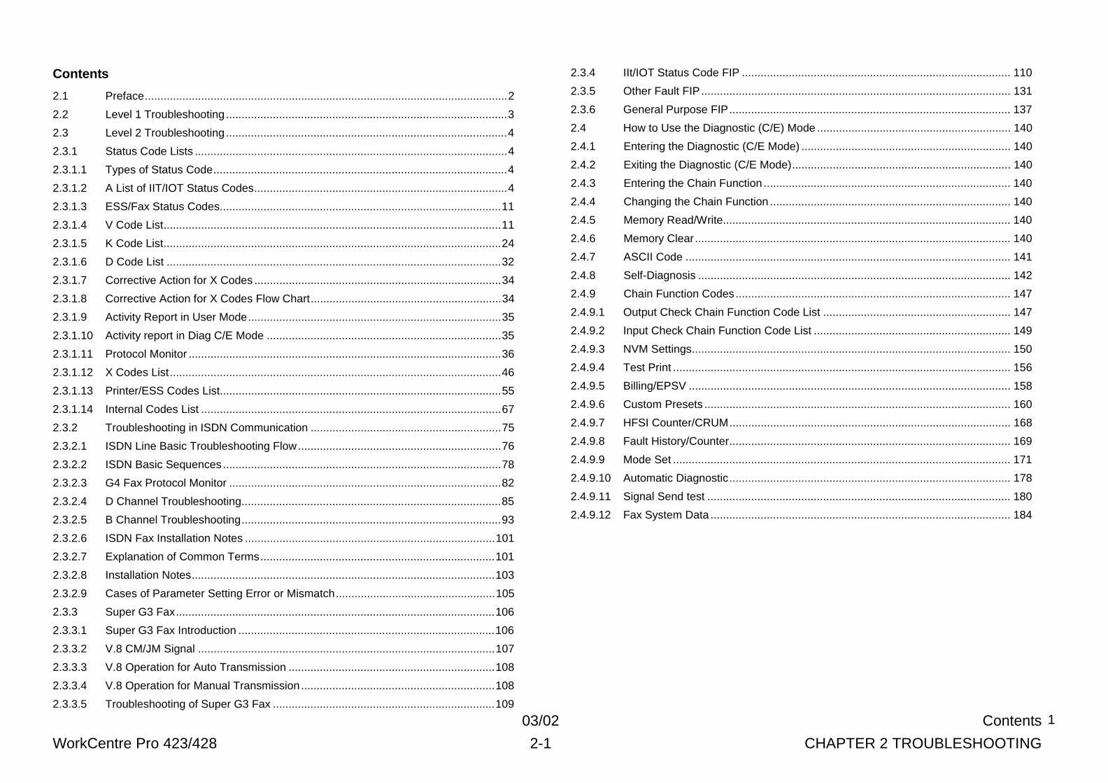
Contents
2.1 Preface....................................................................................................................2
2.2 Level 1 Troubleshooting..........................................................................................3
2.3 Level 2 Troubleshooting..........................................................................................4
2.3.1 Status Code Lists ....................................................................................................4
2.3.1.1 Types of Status Code..............................................................................................4
2.3.1.2 A List of IIT/IOT Status Codes.................................................................................4
2.3.1.3 ESS/Fax Status Codes..........................................................................................11
2.3.1.4 V Code List............................................................................................................11
2.3.1.5 K Code List............................................................................................................24
2.3.1.6 D Code List ...........................................................................................................32
2.3.1.7 Corrective Action for X Codes ...............................................................................34
2.3.1.8 Corrective Action for X Codes Flow Chart.............................................................34
2.3.1.9 Activity Report in User Mode.................................................................................35
2.3.1.10 Activity report in Diag C/E Mode ...........................................................................35
2.3.1.11 Protocol Monitor ....................................................................................................36
2.3.1.12 X Codes List..........................................................................................................46
2.3.1.13 Printer/ESS Codes List..........................................................................................55
2.3.1.14 Internal Codes List ................................................................................................67
2.3.2 Troubleshooting in ISDN Communication .............................................................75
2.3.2.1 ISDN Line Basic Troubleshooting Flow.................................................................76
2.3.2.2 ISDN Basic Sequences .........................................................................................78
2.3.2.3 G4 Fax Protocol Monitor .......................................................................................82
2.3.2.4 D Channel Troubleshooting...................................................................................85
2.3.2.5 B Channel Troubleshooting...................................................................................93
2.3.2.6 ISDN Fax Installation Notes ................................................................................101
2.3.2.7 Explanation of Common Terms...........................................................................101
2.3.2.8 Installation Notes.................................................................................................103
2.3.2.9 Cases of Parameter Setting Error or Mismatch...................................................105
2.3.3 Super G3 Fax......................................................................................................106
2.3.3.1 Super G3 Fax Introduction ..................................................................................106
2.3.3.2 V.8 CM/JM Signal ...............................................................................................107
2.3.3.3 V.8 Operation for Auto Transmission ..................................................................108
2.3.3.4 V.8 Operation for Manual Transmission..............................................................108
2.3.3.5 Troubleshooting of Super G3 Fax .......................................................................109
2.3.4 IIt/IOT Status Code FIP ...................................................................................... 110
2.3.5 Other Fault FIP ................................................................................................... 131
2.3.6 General Purpose FIP.......................................................................................... 137
2.4 How to Use the Diagnostic (C/E) Mode .............................................................. 140
2.4.1 Entering the Diagnostic (C/E Mode) ................................................................... 140
2.4.2 Exiting the Diagnostic (C/E Mode)...................................................................... 140
2.4.3 Entering the Chain Function ............................................................................... 140
2.4.4 Changing the Chain Function ............................................................................. 140
2.4.5 Memory Read/Write............................................................................................ 140
2.4.6 Memory Clear..................................................................................................... 140
2.4.7 ASCII Code ........................................................................................................ 141
2.4.8 Self-Diagnosis .................................................................................................... 142
2.4.9 Chain Function Codes........................................................................................ 147
2.4.9.1 Output Check Chain Function Code List ............................................................ 147
2.4.9.2 Input Check Chain Function Code List ............................................................... 149
2.4.9.3 NVM Settings...................................................................................................... 150
2.4.9.4 Test Print ............................................................................................................ 156
2.4.9.5 Billing/EPSV ....................................................................................................... 158
2.4.9.6 Custom Presets .................................................................................................. 160
2.4.9.7 HFSI Counter/CRUM.......................................................................................... 168
2.4.9.8 Fault History/Counter.......................................................................................... 169
2.4.9.9 Mode Set ............................................................................................................ 171
2.4.9.10 Automatic Diagnostic.......................................................................................... 178
2.4.9.11 Signal Send test ................................................................................................. 180
2.4.9.12 Fax System Data ................................................................................................ 184
WorkCentre Pro 423/428 2-2 CHAPTER 2 TROUBLESHOOTING03/02 2.1 Preface
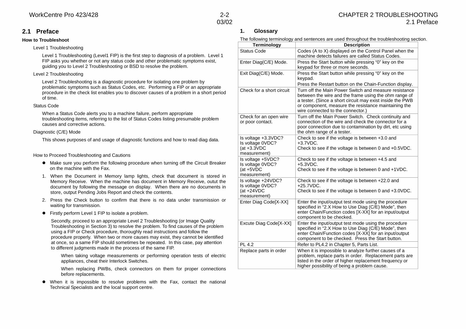
2.1 PrefaceHow to Troubleshoot
Level 1 Troubleshooting
Level 1 Troubleshooting (Level1 FIP) is the first step to diagnosis of a problem. Level 1FIP asks you whether or not any status code and other problematic symptoms exist,guiding you to Level 2 Troubleshooting or BSD to resolve the problem.
Level 2 Troubleshooting
Level 2 Troubleshooting is a diagnostic procedure for isolating one problem byproblematic symptoms such as Status Codes, etc. Performing a FIP or an appropriateprocedure in the check list enables you to discover causes of a problem in a short periodof time.
Status Code
When a Status Code alerts you to a machine failure, perform appropriatetroubleshooting items, referring to the list of Status Codes listing presumable problemcauses and corrective actions.
Diagnostic (C/E) Mode
This shows purposes of and usage of diagnostic functions and how to read diag data.
How to Proceed Troubleshooting and Cautions
l Make sure you perform the following procedure when turning off the Circuit Breakeron the machine with the Fax.
1. When the Document in Memory lamp lights, check that document is stored inMemory Receive. When the machine has document in Memory Receive, outut thedocument by following the message on display. When there are no documents instore, output Pending Jobs Report and check the contents.
2. Press the Check button to confirm that there is no data under transmission orwaiting for transmission.
l Firstly perform Level 1 FIP to isolate a problem.
Secondly, proceed to an appropriate Level 2 Troubleshooting (or Image QualityTroubleshooting in Section 3) to resolve the problem. To find causes of the problemusing a FIP or Check procedure, thoroughly read instructions and follow theprocedure properly. When two or more causes may exist, they cannot be identifiedat once, so a same FIP should sometimes be repeated. In this case, pay attentionto different judgments made in the process of the same FIP.
When taking voltage measurements or performing operation tests of electricappliances, cheat their Interlock Switches.
When replacing PWBs, check connectors on them for proper connectionsbefore replacements.
l When it is impossible to resolve problems with the Fax, contact the nationalTechnical Specialists and the local support centre.
1. GlossaryThe following terminology and sentences are used throughout the troubleshooting section.
Terminology DescriptionStatus Code Codes (A to X) displayed on the Control Panel when the
machine detects failures are called Status Codes.Enter Diag(C/E) Mode. Press the Start button while pressing “0” key on the
keypad for three or more seconds.Exit Diag(C/E) Mode. Press the Start button while pressing “0” key on the
keypad.Press the Restart button on the Chain-Function display.
Check for a short circuit Turn off the Main Power Switch and measure resistancebetween the wire and the frame using the ohm range ofa tester. (Since a short circuit may exist inside the PWBor component, measure the resistance maintaining thewire connected to the connector.)
Check for an open wireor poor contact.
Turn off the Main Power Switch. Check continuity andconnection of the wire and check the connector for apoor connection due to contamination by dirt, etc usingthe ohm range of a tester.
Is voltage +3.3VDC?Is voltage 0VDC?(at +3.3VDCmeasurement)
Check to see if the voltage is between +3.0 and+3.7VDC.Check to see if the voltage is between 0 and +0.5VDC.
Is voltage +5VDC?Is voltage 0VDC?(at +5VDCmeasurement)
Check to see if the voltage is between +4.5 and+5.3VDC.Check to see if the voltage is between 0 and +1VDC.
Is voltage +24VDC?Is voltage 0VDC?(at +24VDCmeasurement)
Check to see if the voltage is between +22.0 and+25.7VDC.Check to see if the voltage is between 0 and +3.0VDC.
Enter Diag Code[X-XX] Enter the input/output test mode using the procedurespecified in “2.X How to Use Diag (C/E) Mode”, thenenter Chain/Function codes [X-XX] for an input/outputcomponent to be checked.
Excute Diag Code[X-XX] Enter the input/output test mode using the procedurespecified in “2.X How to Use Diag (C/E) Mode”, thenenter Chain/Function codes [X-XX] for an input/outputcomponent to be checked. Press the Start button.
PL 4.2 Refer to PL4.2 in Chapter 5, Parts List.Replace parts in order When it is impossible to analyze further causes of a
problem, replace parts in order. Replacement parts arelisted in the order of higher replacement frequency orhigher possibility of being a problem cause.
03/02 2.2 Level 1 Troubleshooting
WorkCentre Pro 423/428 2-3 CHAPTER 2 TROUBLESHOOTING
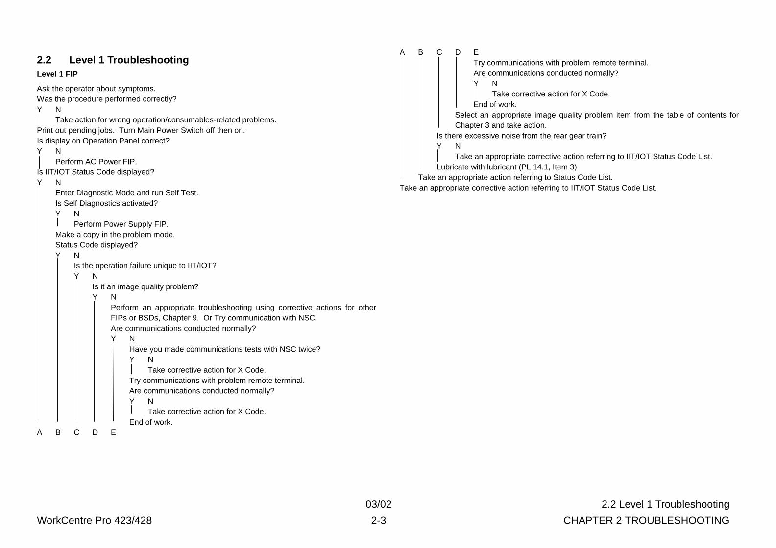
2.2 Level 1 TroubleshootingLevel 1 FIP
Ask the operator about symptoms.Was the procedure performed correctly?Y N
Take action for wrong operation/consumables-related problems.Print out pending jobs. Turn Main Power Switch off then on.Is display on Operation Panel correct?Y N
Perform AC Power FIP.Is IIT/IOT Status Code displayed?Y N
Enter Diagnostic Mode and run Self Test.Is Self Diagnostics activated?Y N
Perform Power Supply FIP.Make a copy in the problem mode.Status Code displayed?Y N
Is the operation failure unique to IIT/IOT?Y N
Is it an image quality problem?Y N
Perform an appropriate troubleshooting using corrective actions for otherFIPs or BSDs, Chapter 9. Or Try communication with NSC.Are communications conducted normally?Y N
Have you made communications tests with NSC twice?Y N
Take corrective action for X Code.Try communications with problem remote terminal.Are communications conducted normally?Y N
Take corrective action for X Code.End of work.
A B C D E
A B C D ETry communications with problem remote terminal.Are communications conducted normally?Y N
Take corrective action for X Code.End of work.
Select an appropriate image quality problem item from the table of contents forChapter 3 and take action.
Is there excessive noise from the rear gear train?Y N
Take an appropriate corrective action referring to IIT/IOT Status Code List.Lubricate with lubricant (PL 14.1, Item 3)
Take an appropriate action referring to Status Code List.Take an appropriate corrective action referring to IIT/IOT Status Code List.

WorkCentre Pro 423/428 2-4 CHAPTER 2 TROUBLESHOOTING03/02 2.3 Level 2 Troubleshooting
2.3 Level 2 Troubleshooting2.3.1 Status Code Lists
2.3.1.1 Types of Status Codesl An-nn: indicates DADF Document Jam, Misfeed, and Interlock Open
l Cn-nn: indicates IOT/DUPLEX misfeeds
l Dn-nn: indicates a system error is detected as a result of Self Diagnostic.
l En-nn: indicates Jams in IOT/DUPLEX Paper Path and Interlock Open
l Fn-nn: Jams in FINISHER and Interlock Open
l Hn-nn: indicates IOT copying/printing are possible but that accessory equipment/featurescannot be used.
l Jn-nn: alerts the operator to “Replacement or Refill of Consumables”
l Kn-nn: indicates “Wrong Operation” by the operator when the fax is used.
l Ln-nn: indicates related products (accessories) are not installed
l Un-nn: indicates IOT System Error is detected and that copying/printing are impossible.
l UE-nn: EPSV-related interface error status
l Vn-nn: Fax system error status
l Xn-nn: indicates a fax communication failure is detected.
l ChainXX-LinkXX: ESS-related fault detection status
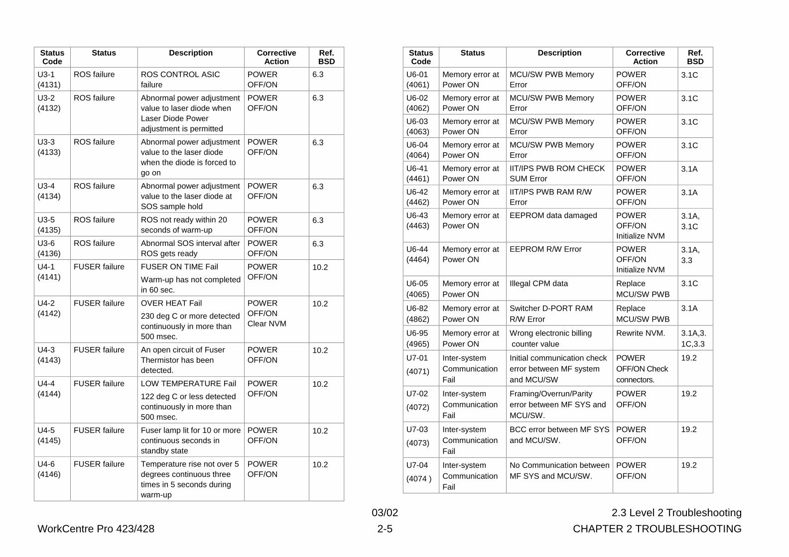
2.3.1.2 A List of IIT/IOT Status Codes (nnnn) indicates an internal code corresponding to Status code.StatusCode
Status Description CorrectiveAction
Ref.BSD
U0-01(4001)
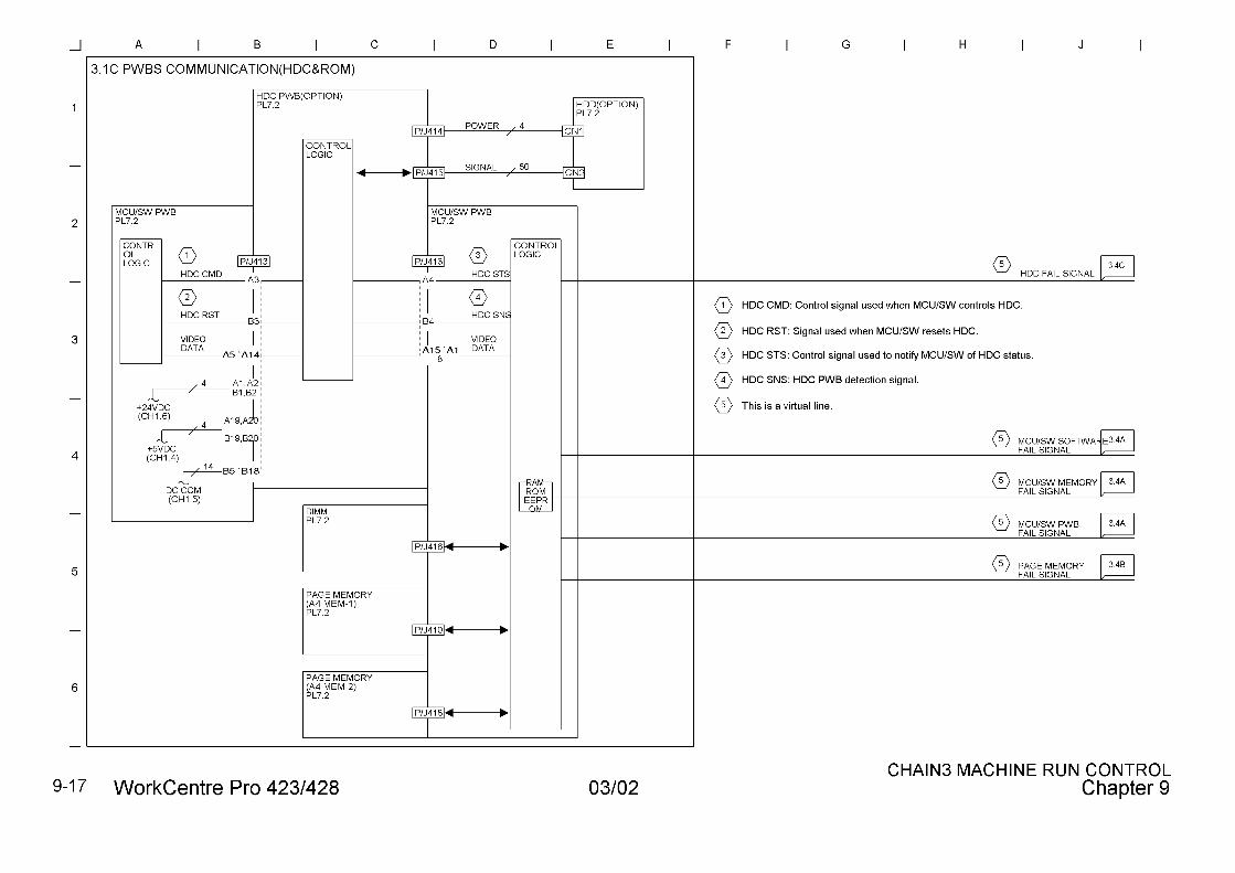
DCSYSSoftware failure
Undefined interrupt such asBreak command and 0subtraction
Power OFF/ON 3.1C
U0-02(4002)
DCSYSSoftware failure
MC status transition failure Power OFF/ON 3.1C
U0-03(40A0)
DCSYSSoftware failure
Main Box(MCU)
communications failurebetween tasks
Power OFF/ON 3.1C
U0-04(4004)
DCSYSSoftware failure
Wrong job startingparameter
Power OFF/ON 3.1C
U0-05(4005)
DCSYSSoftware failure
Job control failure Power OFF/ON 3.1C
U0-06(4006)
DCSYSSoftware failure
Paper at regi section. Don’tstart Printing(blank purge)
Power OFF/ON 3.1C
U0-07(4007)
DCSYSSoftware failure
Main Motor keeps on beingenergized
Power OFF/ON 3.1C
U0-08(4008)
DCSYSSoftware failure
Parameter failure forstopping jobs
Power OFF/ON 3.1C
U0-09(4009)
DCSYSSoftware failure
Unable to stop the job(Aborted)
Power OFF/ON 3.1C
U1-1(4111)
MAIN MOTORfailure
M/C Clock Fail POWEROFF/ON
4.1
U1-2(4112)
FAN failure FUSER FAN failure POWEROFF/ON
10.1
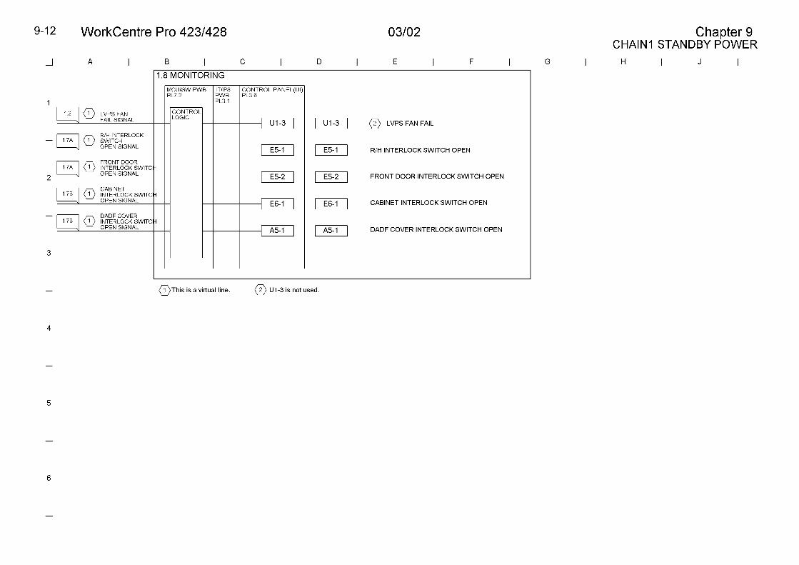
U1-3(4113)
FAN failure LVPS FAN failure POWEROFF/ON
1.2
U2-1(4421)
Carriage failure IIT REGI SENSOR has keptactuated.
POWEROFF/ON
6.2
U2-2(4112)
Carriage failure IIT REGI SENSOR has notbeen actuated.
POWEROFF/ON
6.2
U2-3(4113)
Carriage failure A difference of 10 pulses ormore in Motor pulsebetween Scan and ReturnCarriages
POWEROFF/ON
6.2
03/02 2.3 Level 2 Troubleshooting
WorkCentre Pro 423/428 2-5 CHAPTER 2 TROUBLESHOOTING
StatusCode
Status Description CorrectiveAction
Ref.BSD
U3-1(4131)
ROS failure ROS CONTROL ASICfailure
POWEROFF/ON
6.3
U3-2(4132)
ROS failure Abnormal power adjustmentvalue to laser diode whenLaser Diode Poweradjustment is permitted
POWEROFF/ON
6.3
U3-3(4133)
ROS failure Abnormal power adjustmentvalue to the laser diodewhen the diode is forced togo on
POWEROFF/ON
6.3
U3-4(4134)
ROS failure Abnormal power adjustmentvalue to the laser diode atSOS sample hold
POWEROFF/ON
6.3
U3-5(4135)
ROS failure ROS not ready within 20seconds of warm-up
POWEROFF/ON
6.3
U3-6(4136)
ROS failure Abnormal SOS interval afterROS gets ready
POWEROFF/ON
6.3
U4-1(4141)
FUSER failure FUSER ON TIME Fail
Warm-up has not completedin 60 sec.
POWEROFF/ON
10.2
U4-2(4142)
FUSER failure OVER HEAT Fail
230 deg C or more detectedcontinuously in more than500 msec.
POWEROFF/ONClear NVM
10.2
U4-3(4143)
FUSER failure An open circuit of FuserThermistor has beendetected.
POWEROFF/ON
10.2
U4-4(4144)
FUSER failure LOW TEMPERATURE Fail
122 deg C or less detectedcontinuously in more than500 msec.
POWEROFF/ON
10.2
U4-5(4145)
FUSER failure Fuser lamp lit for 10 or morecontinuous seconds instandby state
POWEROFF/ON
10.2
U4-6(4146)
FUSER failure Temperature rise not over 5degrees continuous threetimes in 5 seconds duringwarm-up
POWEROFF/ON
10.2
StatusCode
Status Description CorrectiveAction
Ref.BSD
U6-01(4061)
Memory error atPower ON
MCU/SW PWB MemoryError
POWEROFF/ON
3.1C
U6-02(4062)
Memory error atPower ON
MCU/SW PWB MemoryError
POWEROFF/ON
3.1C
U6-03(4063)
Memory error atPower ON
MCU/SW PWB MemoryError
POWEROFF/ON
3.1C
U6-04(4064)
Memory error atPower ON
MCU/SW PWB MemoryError
POWEROFF/ON
3.1C
U6-41(4461)
Memory error atPower ON
IIT/IPS PWB ROM CHECKSUM Error
POWEROFF/ON
3.1A
U6-42(4462)
Memory error atPower ON
IIT/IPS PWB RAM R/WError
POWEROFF/ON
3.1A
U6-43(4463)
Memory error atPower ON
EEPROM data damaged POWEROFF/ONInitialize NVM
3.1A,3.1C
U6-44(4464)
Memory error atPower ON
EEPROM R/W Error POWEROFF/ONInitialize NVM
3.1A,3.3
U6-05(4065)
Memory error atPower ON
Illegal CPM data ReplaceMCU/SW PWB
3.1C
U6-82(4862)
Memory error atPower ON
Switcher D-PORT RAMR/W Error
ReplaceMCU/SW PWB
3.1A
U6-95(4965)
Memory error atPower ON
Wrong electronic billingcounter value
Rewrite NVM. 3.1A,3.1C,3.3
U7-01
(4071)
Inter-systemCommunicationFail
Initial communication checkerror between MF systemand MCU/SW
POWEROFF/ON Checkconnectors.
19.2
U7-02
(4072)
Inter-systemCommunicationFail
Framing/Overrun/Parityerror between MF SYS andMCU/SW.
POWEROFF/ON
19.2
U7-03
(4073)
Inter-systemCommunicationFail
BCC error between MF SYSand MCU/SW.
POWEROFF/ON
19.2
U7-04
(4074 )
Inter-systemCommunicationFail
No Communication betweenMF SYS and MCU/SW.
POWEROFF/ON
19.2
WorkCentre Pro 423/428 2-6 CHAPTER 2 TROUBLESHOOTING03/02 2.3 Level 2 Troubleshooting
StatusCode
Status Description CorrectiveAction
Ref.BSD
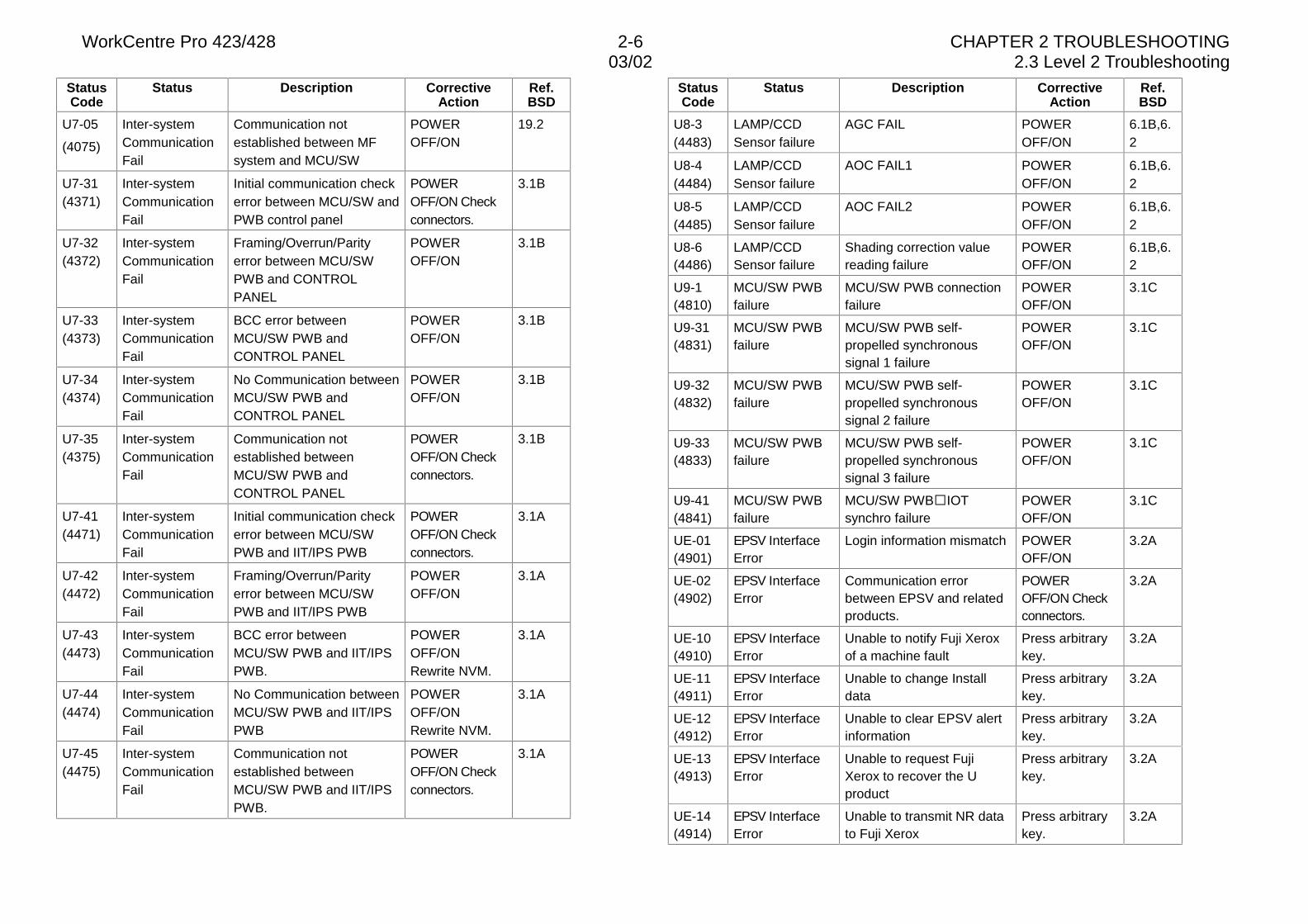
U7-05
(4075)
Inter-systemCommunicationFail
Communication notestablished between MFsystem and MCU/SW
POWEROFF/ON
19.2
U7-31(4371)
Inter-systemCommunicationFail
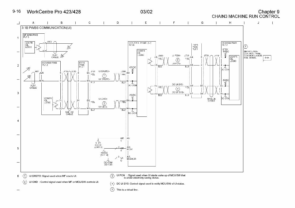
Initial communication checkerror between MCU/SW andPWB control panel
POWEROFF/ON Checkconnectors.
3.1B
U7-32(4372)
Inter-systemCommunicationFail
Framing/Overrun/Parityerror between MCU/SWPWB and CONTROLPANEL
POWEROFF/ON
3.1B
U7-33(4373)
Inter-systemCommunicationFail
BCC error betweenMCU/SW PWB andCONTROL PANEL
POWEROFF/ON
3.1B
U7-34(4374)
Inter-systemCommunicationFail
No Communication betweenMCU/SW PWB andCONTROL PANEL
POWEROFF/ON
3.1B
U7-35(4375)
Inter-systemCommunicationFail
Communication notestablished betweenMCU/SW PWB andCONTROL PANEL
POWEROFF/ON Checkconnectors.
3.1B
U7-41(4471)
Inter-systemCommunicationFail
Initial communication checkerror between MCU/SWPWB and IIT/IPS PWB
POWEROFF/ON Checkconnectors.
3.1A
U7-42(4472)
Inter-systemCommunicationFail
Framing/Overrun/Parityerror between MCU/SWPWB and IIT/IPS PWB
POWEROFF/ON
3.1A
U7-43(4473)
Inter-systemCommunicationFail
BCC error betweenMCU/SW PWB and IIT/IPSPWB.
POWEROFF/ONRewrite NVM.
3.1A
U7-44(4474)
Inter-systemCommunicationFail
No Communication betweenMCU/SW PWB and IIT/IPSPWB
POWEROFF/ONRewrite NVM.
3.1A
U7-45(4475)
Inter-systemCommunicationFail
Communication notestablished betweenMCU/SW PWB and IIT/IPSPWB.
POWEROFF/ON Checkconnectors.
3.1A
StatusCode
Status Description CorrectiveAction
Ref.BSD
U8-3(4483)
LAMP/CCDSensor failure
AGC FAIL POWEROFF/ON
6.1B,6.2
U8-4(4484)
LAMP/CCDSensor failure
AOC FAIL1 POWEROFF/ON
6.1B,6.2
U8-5(4485)
LAMP/CCDSensor failure
AOC FAIL2 POWEROFF/ON
6.1B,6.2
U8-6(4486)
LAMP/CCDSensor failure
Shading correction valuereading failure
POWEROFF/ON
6.1B,6.2
U9-1(4810)
MCU/SW PWBfailure
MCU/SW PWB connectionfailure
POWEROFF/ON
3.1C
U9-31(4831)
MCU/SW PWBfailure
MCU/SW PWB self-propelled synchronoussignal 1 failure
POWEROFF/ON
3.1C
U9-32(4832)
MCU/SW PWBfailure
MCU/SW PWB self-propelled synchronoussignal 2 failure
POWEROFF/ON
3.1C
U9-33(4833)
MCU/SW PWBfailure
MCU/SW PWB self-propelled synchronoussignal 3 failure
POWEROFF/ON
3.1C
U9-41(4841)
MCU/SW PWBfailure
MCU/SW PWB�IOTsynchro failure
POWEROFF/ON
3.1C
UE-01(4901)
EPSV InterfaceError
Login information mismatch POWEROFF/ON
3.2A
UE-02(4902)
EPSV InterfaceError
Communication errorbetween EPSV and relatedproducts.
POWEROFF/ON Checkconnectors.
3.2A
UE-10(4910)
EPSV InterfaceError
Unable to notify Fuji Xeroxof a machine fault
Press arbitrarykey.
3.2A
UE-11(4911)
EPSV InterfaceError
Unable to change Installdata
Press arbitrarykey.
3.2A
UE-12(4912)
EPSV InterfaceError
Unable to clear EPSV alertinformation
Press arbitrarykey.
3.2A
UE-13(4913)
EPSV InterfaceError
Unable to request FujiXerox to recover the Uproduct
Press arbitrarykey.
3.2A
UE-14(4914)
EPSV InterfaceError
Unable to transmit NR datato Fuji Xerox
Press arbitrarykey.
3.2A
03/02 2.3 Level 2 Troubleshooting
WorkCentre Pro 423/428 2-7 CHAPTER 2 TROUBLESHOOTING
StatusCode
Status Description CorrectiveAction
Ref.BSD
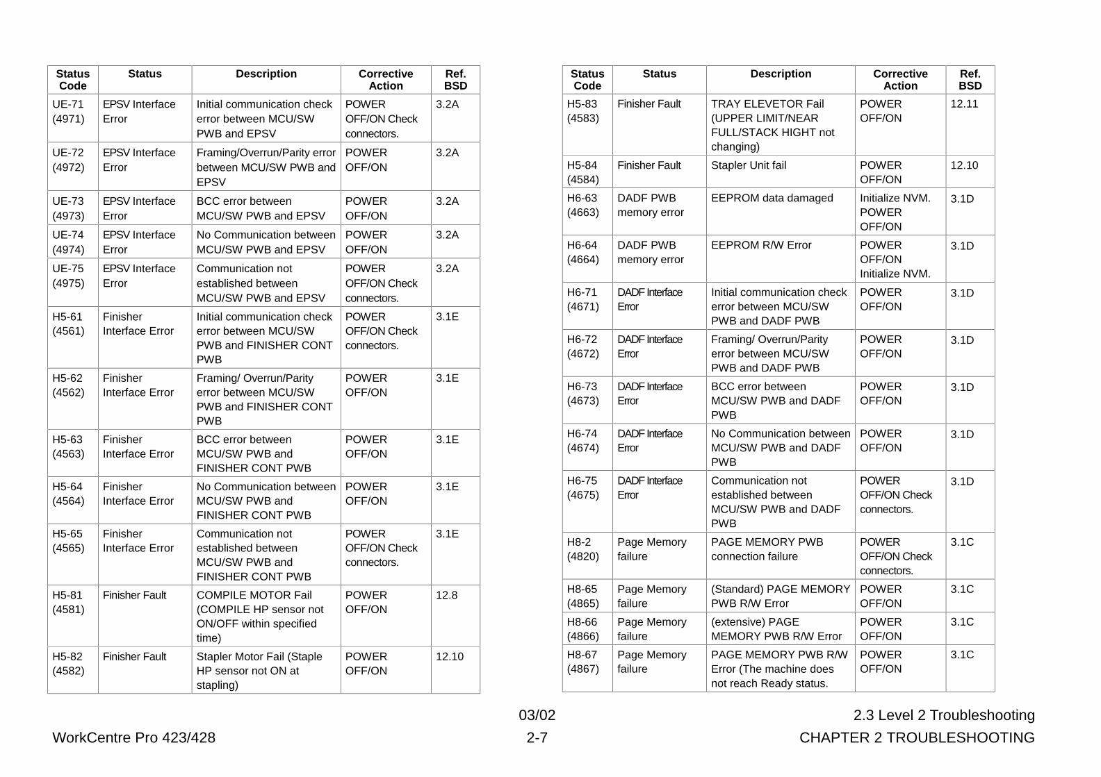
UE-71(4971)
EPSV InterfaceError
Initial communication checkerror between MCU/SWPWB and EPSV
POWEROFF/ON Checkconnectors.
3.2A
UE-72(4972)
EPSV InterfaceError
Framing/Overrun/Parity errorbetween MCU/SW PWB andEPSV
POWEROFF/ON
3.2A
UE-73(4973)
EPSV InterfaceError
BCC error betweenMCU/SW PWB and EPSV
POWEROFF/ON
3.2A
UE-74(4974)
EPSV InterfaceError
No Communication betweenMCU/SW PWB and EPSV
POWEROFF/ON
3.2A
UE-75(4975)
EPSV InterfaceError
Communication notestablished betweenMCU/SW PWB and EPSV
POWEROFF/ON Checkconnectors.
3.2A
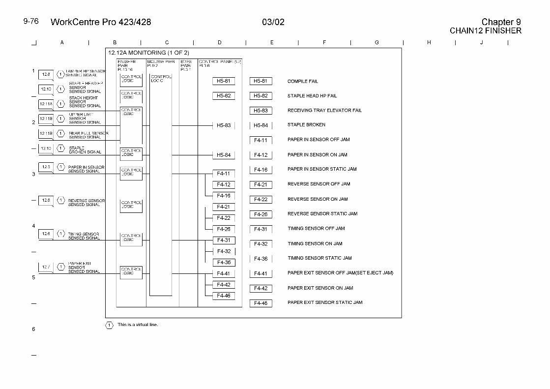
H5-61(4561)
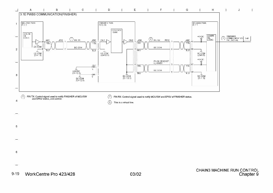
FinisherInterface Error
Initial communication checkerror between MCU/SWPWB and FINISHER CONTPWB
POWEROFF/ON Checkconnectors.
3.1E
H5-62(4562)
FinisherInterface Error
Framing/ Overrun/Parityerror between MCU/SWPWB and FINISHER CONTPWB
POWEROFF/ON
3.1E
H5-63(4563)
FinisherInterface Error
BCC error betweenMCU/SW PWB andFINISHER CONT PWB
POWEROFF/ON
3.1E
H5-64(4564)
FinisherInterface Error
No Communication betweenMCU/SW PWB andFINISHER CONT PWB
POWEROFF/ON
3.1E
H5-65(4565)
FinisherInterface Error
Communication notestablished betweenMCU/SW PWB andFINISHER CONT PWB
POWEROFF/ON Checkconnectors.
3.1E
H5-81(4581)
Finisher Fault COMPILE MOTOR Fail(COMPILE HP sensor notON/OFF within specifiedtime)
POWEROFF/ON
12.8
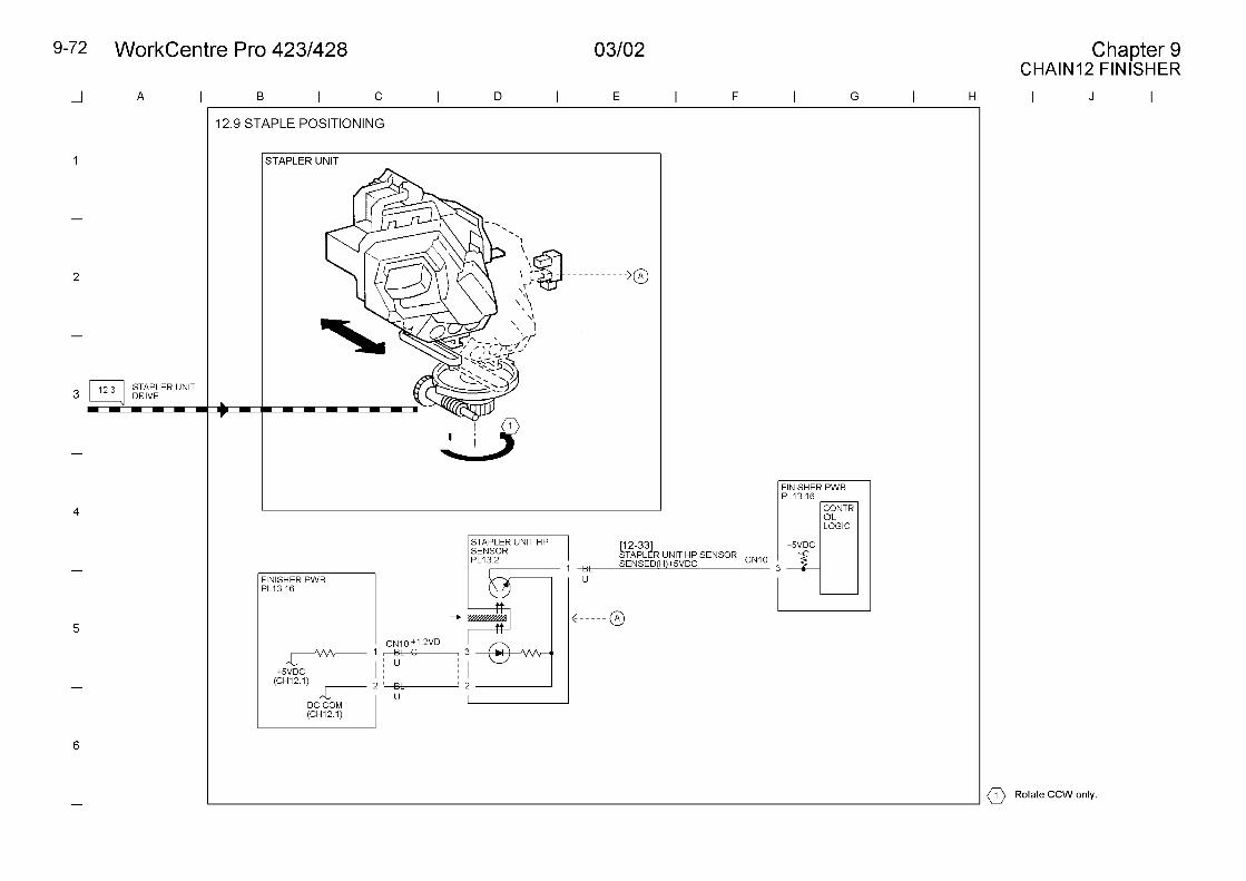
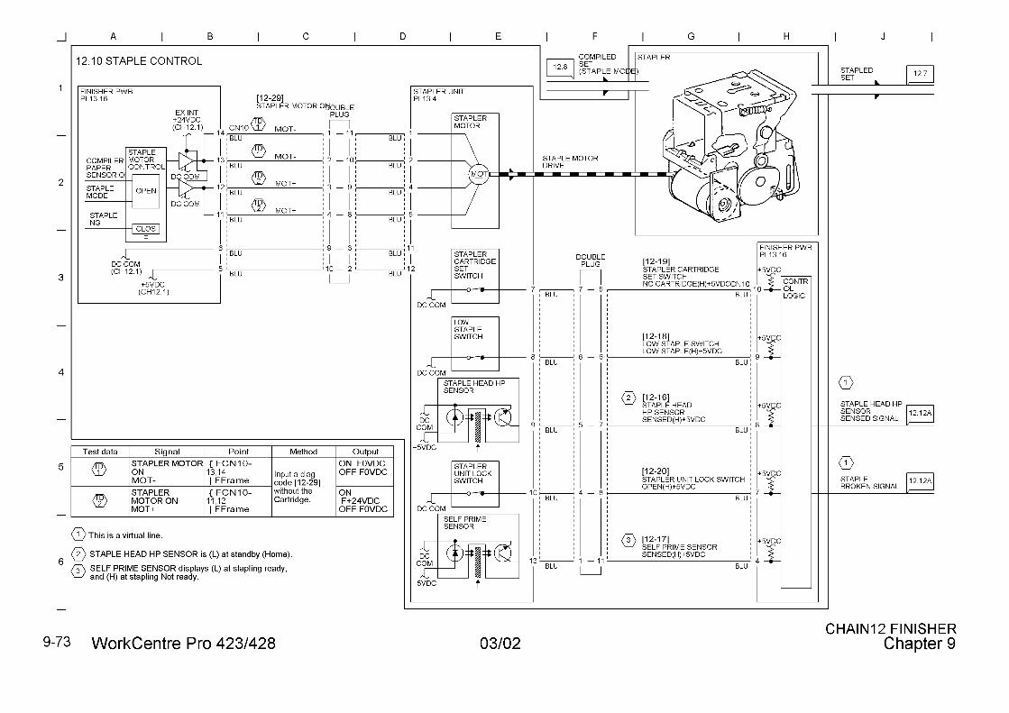
H5-82(4582)
Finisher Fault Stapler Motor Fail (StapleHP sensor not ON atstapling)
POWEROFF/ON
12.10
StatusCode
Status Description CorrectiveAction
Ref.BSD
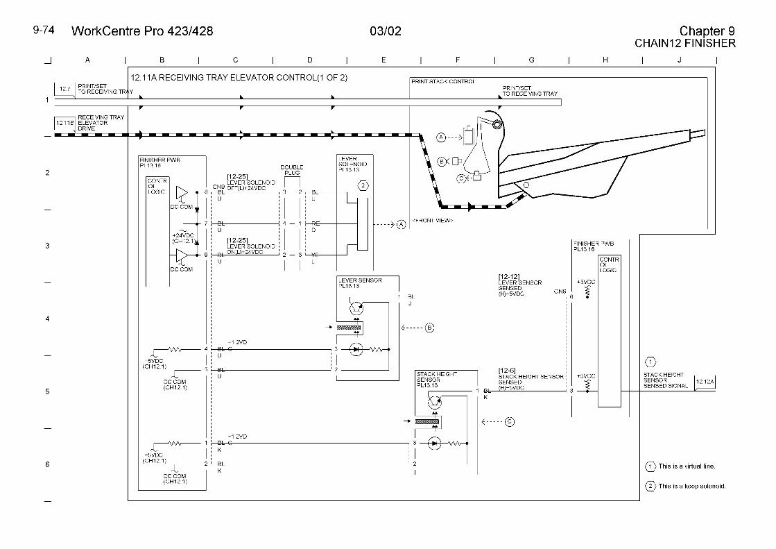
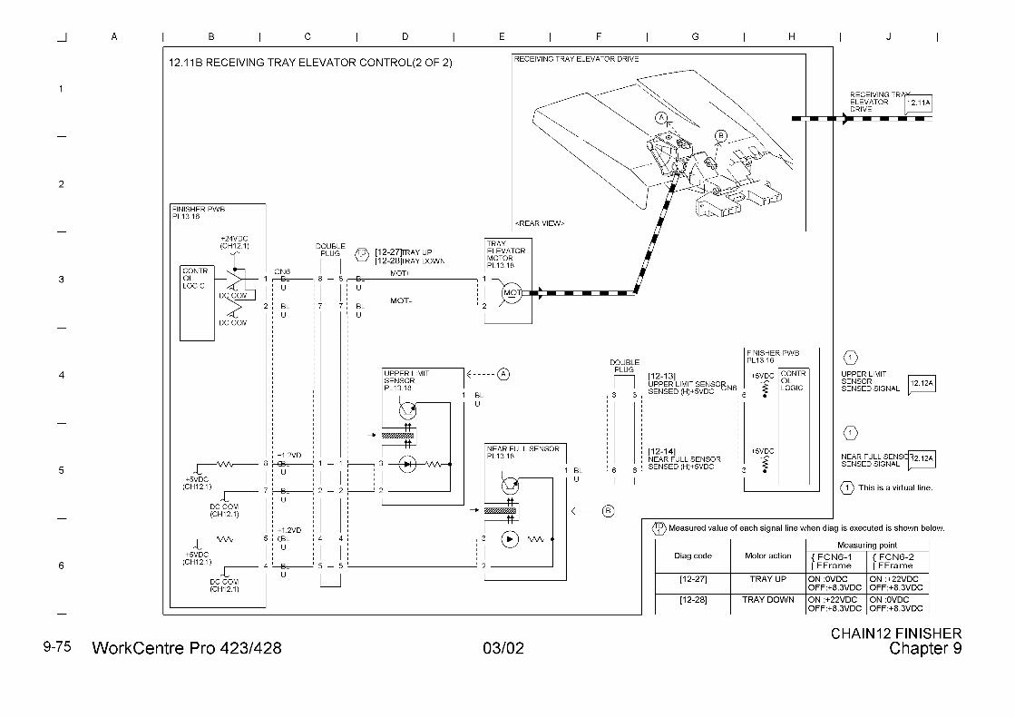
H5-83(4583)
Finisher Fault TRAY ELEVETOR Fail(UPPER LIMIT/NEARFULL/STACK HIGHT notchanging)
POWEROFF/ON
12.11
H5-84(4584)
Finisher Fault Stapler Unit fail POWEROFF/ON
12.10
H6-63(4663)
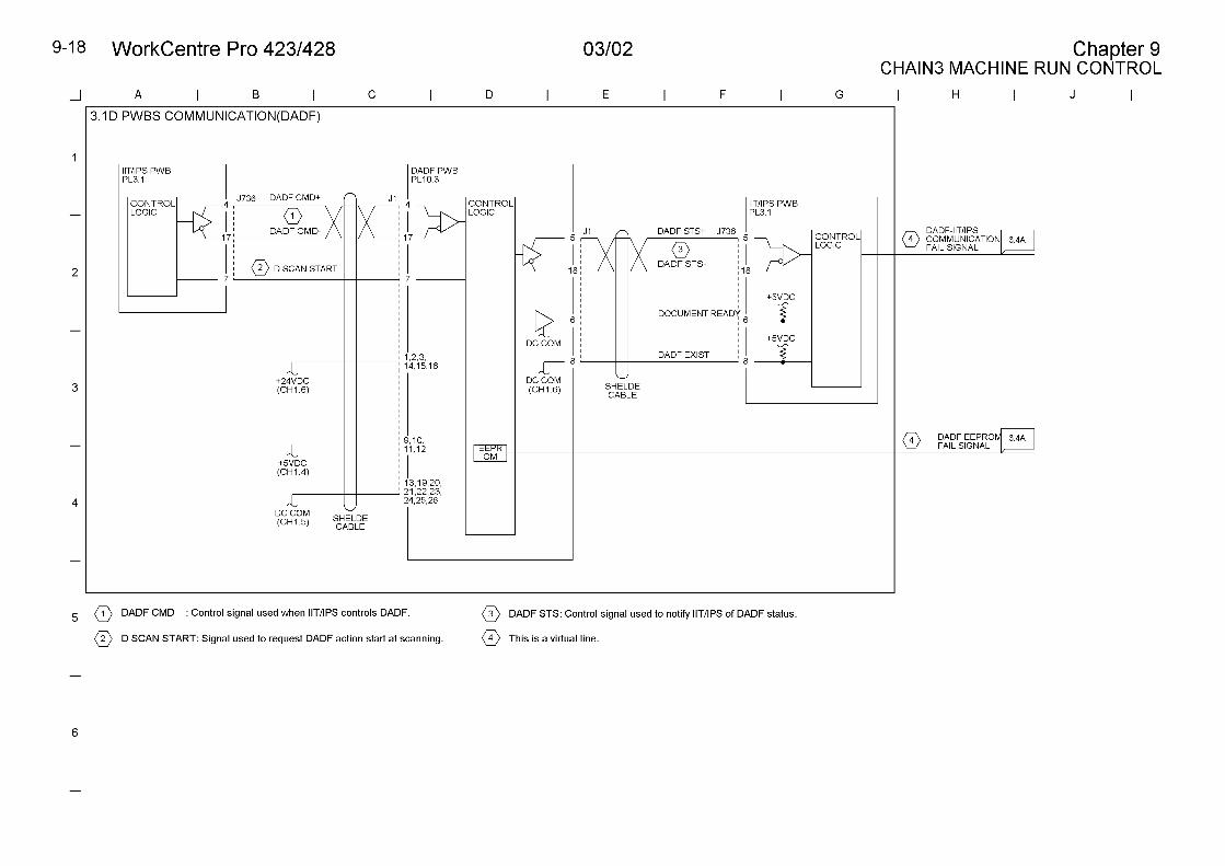
DADF PWBmemory error
EEPROM data damaged Initialize NVM.POWEROFF/ON
3.1D
H6-64(4664)
DADF PWBmemory error
EEPROM R/W Error POWEROFF/ONInitialize NVM.
3.1D
H6-71(4671)
DADF InterfaceError
Initial communication checkerror between MCU/SWPWB and DADF PWB
POWEROFF/ON
3.1D
H6-72(4672)
DADF InterfaceError
Framing/ Overrun/Parityerror between MCU/SWPWB and DADF PWB
POWEROFF/ON
3.1D
H6-73(4673)
DADF InterfaceError
BCC error betweenMCU/SW PWB and DADFPWB
POWEROFF/ON
3.1D
H6-74(4674)
DADF InterfaceError
No Communication betweenMCU/SW PWB and DADFPWB
POWEROFF/ON
3.1D
H6-75(4675)
DADF InterfaceError
Communication notestablished betweenMCU/SW PWB and DADFPWB
POWEROFF/ON Checkconnectors.
3.1D
H8-2(4820)
Page Memoryfailure
PAGE MEMORY PWBconnection failure
POWEROFF/ON Checkconnectors.
3.1C
H8-65(4865)
Page Memoryfailure
(Standard) PAGE MEMORYPWB R/W Error
POWEROFF/ON
3.1C
H8-66(4866)
Page Memoryfailure
(extensive) PAGEMEMORY PWB R/W Error
POWEROFF/ON
3.1C
H8-67(4867)
Page Memoryfailure
PAGE MEMORY PWB R/WError (The machine doesnot reach Ready status.
POWEROFF/ON
3.1C
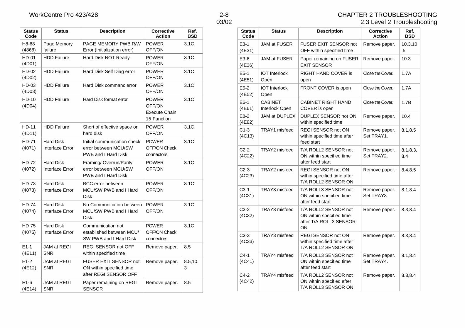
WorkCentre Pro 423/428 2-8 CHAPTER 2 TROUBLESHOOTING03/02 2.3 Level 2 Troubleshooting
StatusCode
Status Description CorrectiveAction
Ref.BSD
H8-68(4868)
Page Memoryfailure
PAGE MEMORY PWB R/WError (Initialization error)
POWEROFF/ON
3.1C
HD-01(4D01)
HDD Failure Hard Disk NOT Ready POWEROFF/ON
3.1C
HD-02(4D02)
HDD Failure Hard Disk Self Diag error POWEROFF/ON
3.1C
HD-03(4D03)
HDD Failure Hard Disk commanc error POWEROFF/ON
3.1C
HD-10(4D04)
HDD Failure Hard Disk format error POWEROFF/ONExecute Chain15-Function
3.1C
HD-11(4D11)
HDD Failure Short of effective space onhard disk
POWEROFF/ON
3.1C
HD-71(4071)
Hard DiskInterface Error
Initial communication checkerror between MCU/SWPWB and I Hard Disk
POWEROFF/ON Checkconnectors.
3.1C
HD-72(4072)
Hard DiskInterface Error
Framing/ Overrun/Parityerror between MCU/SWPWB and I Hard Disk
POWEROFF/ON
3.1C
HD-73(4073)
Hard DiskInterface Error
BCC error betweenMCU/SW PWB and I HardDisk
POWEROFF/ON
3.1C
HD-74(4074)
Hard DiskInterface Error
No Communication betweenMCU/SW PWB and I HardDisk
POWEROFF/ON
3.1C
HD-75(4075)
Hard DiskInterface Error
Communication notestablished between MCU/SW PWB and I Hard Disk
POWEROFF/ON Checkconnectors.
3.1C
E1-1(4E11)
JAM at REGISNR
REGI SENSOR not OFFwithin specified time
Remove paper. 8.5
E1-2(4E12)
JAM at REGISNR
FUSER EXIT SENSOR notON within specified timeafter REGI SENSOR OFF
Remove paper. 8.5,10.3
E1-6(4E14)
JAM at REGISNR
Paper remaining on REGISENSOR
Remove paper. 8.5
StatusCode
Status Description CorrectiveAction
Ref.BSD
E3-1(4E31)
JAM at FUSER FUSER EXIT SENSOR notOFF within specified time
Remove paper. 10.3,10.5
E3-6(4E36)
JAM at FUSER Paper remaining on FUSEREXIT SENSOR
Remove paper. 10.3
E5-1(4E51)
IOT InterlockOpen
RIGHT HAND COVER isopen
Close the Cover. 1.7A
E5-2(4E52)
IOT InterlockOpen
FRONT COVER is open Close the Cover. 1.7A
E6-1(4E61)
CABINETInterlock Open
CABINET RIGHT HANDCOVER is open
Close the Cover. 1.7B
E8-2(4E82)
JAM at DUPLEX DUPLEX SENSOR not ONwithin specified time
Remove paper. 10.4
C1-3(4C13)
TRAY1 misfeed REGI SENSOR not ONwithin specified time afterfeed start
Remove paper.Set TRAY1.
8.1,8.5
C2-2(4C22)
TRAY2 misfeed T/A ROLL2 SENSOR notON within specified timeafter feed start
Remove paper.Set TRAY2.
8.1,8.3,8.4
C2-3(4C23)
TRAY2 misfeed REGI SENSOR not ONwithin specified time afterT/A ROLL2 SENSOR ON
Remove paper. 8.4,8.5
C3-1(4C31)
TRAY3 misfeed T/A ROLL3 SENSOR notON within specified timeafter feed start
Remove paper.Set TRAY3.
8.1,8.4
C3-2(4C32)
TRAY3 misfeed T/A ROLL2 SENSOR notON within specified timeafter T/A ROLL3 SENSORON
Remove paper. 8.3,8.4
C3-3(4C33)
TRAY3 misfeed REGI SENSOR not ONwithin specified time afterT/A ROLL2 SENSOR ON
Remove paper. 8.3,8.4
C4-1(4C41)
TRAY4 misfeed T/A ROLL3 SENSOR notON within specified timeafter feed start
Remove paper.Set TRAY4.
8.1,8.4
C4-2(4C42)
TRAY4 misfeed T/A ROLL2 SENSOR notON within specified afterT/A ROLL3 SENSOR ON
Remove paper. 8.3,8.4
03/02 2.3 Level 2 Troubleshooting
WorkCentre Pro 423/428 2-9 CHAPTER 2 TROUBLESHOOTING
StatusCode
Status Description CorrectiveAction
Ref.BSD
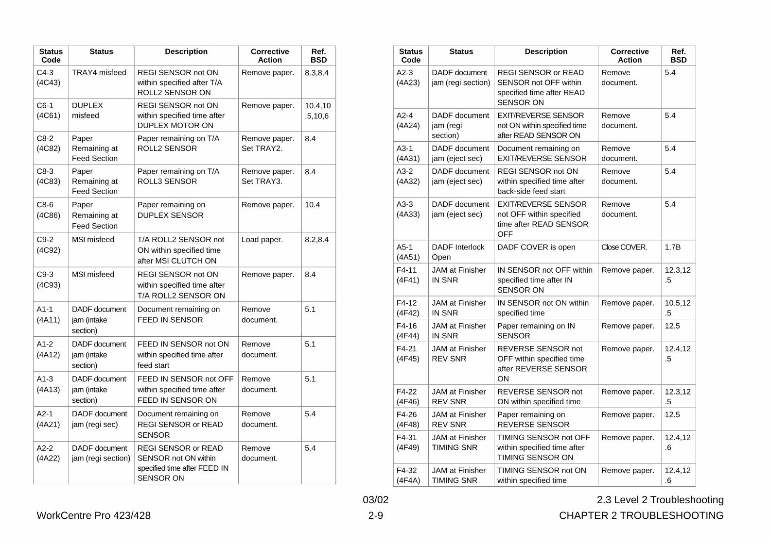
C4-3(4C43)
TRAY4 misfeed REGI SENSOR not ONwithin specified after T/AROLL2 SENSOR ON
Remove paper. 8.3,8.4
C6-1(4C61)
DUPLEXmisfeed
REGI SENSOR not ONwithin specified time afterDUPLEX MOTOR ON
Remove paper. 10.4,10.5,10,6
C8-2(4C82)
PaperRemaining atFeed Section
Paper remaining on T/AROLL2 SENSOR
Remove paper.Set TRAY2.
8.4
C8-3(4C83)
PaperRemaining atFeed Section
Paper remaining on T/AROLL3 SENSOR
Remove paper.Set TRAY3.
8.4
C8-6(4C86)
PaperRemaining atFeed Section
Paper remaining onDUPLEX SENSOR
Remove paper. 10.4
C9-2(4C92)
MSI misfeed T/A ROLL2 SENSOR notON within specified timeafter MSI CLUTCH ON
Load paper. 8.2,8.4
C9-3(4C93)
MSI misfeed REGI SENSOR not ONwithin specified time afterT/A ROLL2 SENSOR ON
Remove paper. 8.4
A1-1(4A11)
DADF documentjam (intakesection)
Document remaining onFEED IN SENSOR
Removedocument.
5.1
A1-2(4A12)
DADF documentjam (intakesection)
FEED IN SENSOR not ONwithin specified time afterfeed start
Removedocument.
5.1
A1-3(4A13)
DADF documentjam (intakesection)
FEED IN SENSOR not OFFwithin specified time afterFEED IN SENSOR ON
Removedocument.
5.1
A2-1(4A21)
DADF documentjam (regi sec)
Document remaining onREGI SENSOR or READSENSOR
Removedocument.
5.4
A2-2(4A22)
DADF documentjam (regi section)
REGI SENSOR or READSENSOR not ON withinspecified time after FEED INSENSOR ON
Removedocument.
5.4
StatusCode
Status Description CorrectiveAction
Ref.BSD
A2-3(4A23)
DADF documentjam (regi section)
REGI SENSOR or READSENSOR not OFF withinspecified time after READSENSOR ON
Removedocument.
5.4
A2-4(4A24)
DADF documentjam (regisection)
EXIT/REVERSE SENSORnot ON within specified timeafter READ SENSOR ON
Removedocument.
5.4
A3-1(4A31)
DADF documentjam (eject sec)
Document remaining onEXIT/REVERSE SENSOR
Removedocument.
5.4
A3-2(4A32)
DADF documentjam (eject sec)
REGI SENSOR not ONwithin specified time afterback-side feed start
Removedocument.
5.4
A3-3(4A33)
DADF documentjam (eject sec)
EXIT/REVERSE SENSORnot OFF within specifiedtime after READ SENSOROFF
Removedocument.
5.4
A5-1(4A51)
DADF InterlockOpen
DADF COVER is open Close COVER. 1.7B
F4-11(4F41)
JAM at FinisherIN SNR
IN SENSOR not OFF withinspecified time after INSENSOR ON
Remove paper. 12.3,12.5
F4-12(4F42)
JAM at FinisherIN SNR
IN SENSOR not ON withinspecified time
Remove paper. 10.5,12.5
F4-16(4F44)
JAM at FinisherIN SNR
Paper remaining on INSENSOR
Remove paper. 12.5
F4-21(4F45)
JAM at FinisherREV SNR
REVERSE SENSOR notOFF within specified timeafter REVERSE SENSORON
Remove paper. 12.4,12.5
F4-22(4F46)
JAM at FinisherREV SNR
REVERSE SENSOR notON within specified time
Remove paper. 12.3,12.5
F4-26(4F48)
JAM at FinisherREV SNR
Paper remaining onREVERSE SENSOR
Remove paper. 12.5
F4-31(4F49)
JAM at FinisherTIMING SNR
TIMING SENSOR not OFFwithin specified time afterTIMING SENSOR ON
Remove paper. 12.4,12.6
F4-32(4F4A)
JAM at FinisherTIMING SNR
TIMING SENSOR not ONwithin specified time
Remove paper. 12.4,12.6
WorkCentre Pro 423/428 2-10 CHAPTER 2 TROUBLESHOOTING03/02 2.3 Level 2 Troubleshooting
StatusCode
Status Description CorrectiveAction
Ref.BSD
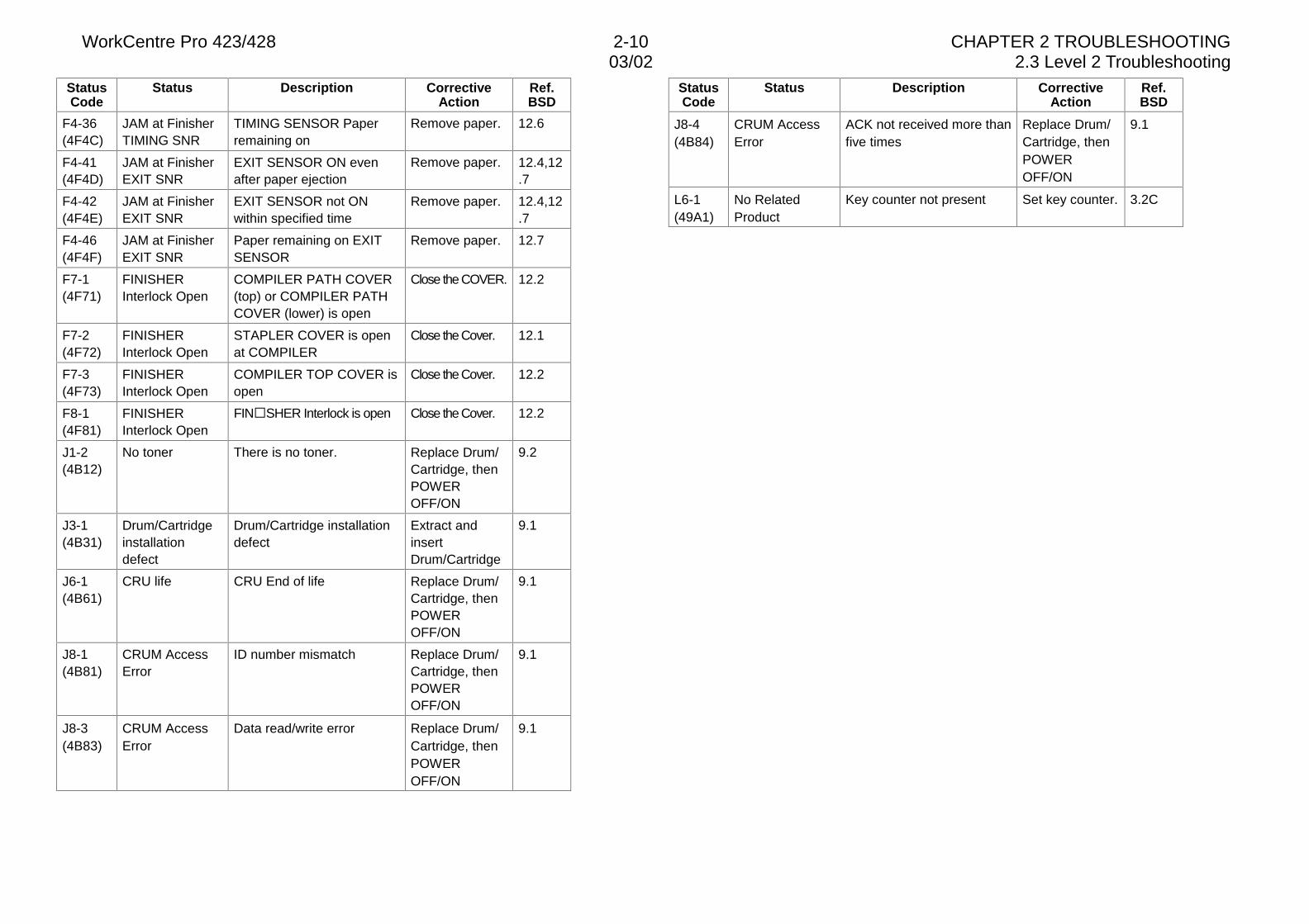
F4-36(4F4C)
JAM at FinisherTIMING SNR
TIMING SENSOR Paperremaining on
Remove paper. 12.6
F4-41(4F4D)
JAM at FinisherEXIT SNR
EXIT SENSOR ON evenafter paper ejection
Remove paper. 12.4,12.7
F4-42(4F4E)
JAM at FinisherEXIT SNR
EXIT SENSOR not ONwithin specified time
Remove paper. 12.4,12.7
F4-46(4F4F)
JAM at FinisherEXIT SNR
Paper remaining on EXITSENSOR
Remove paper. 12.7
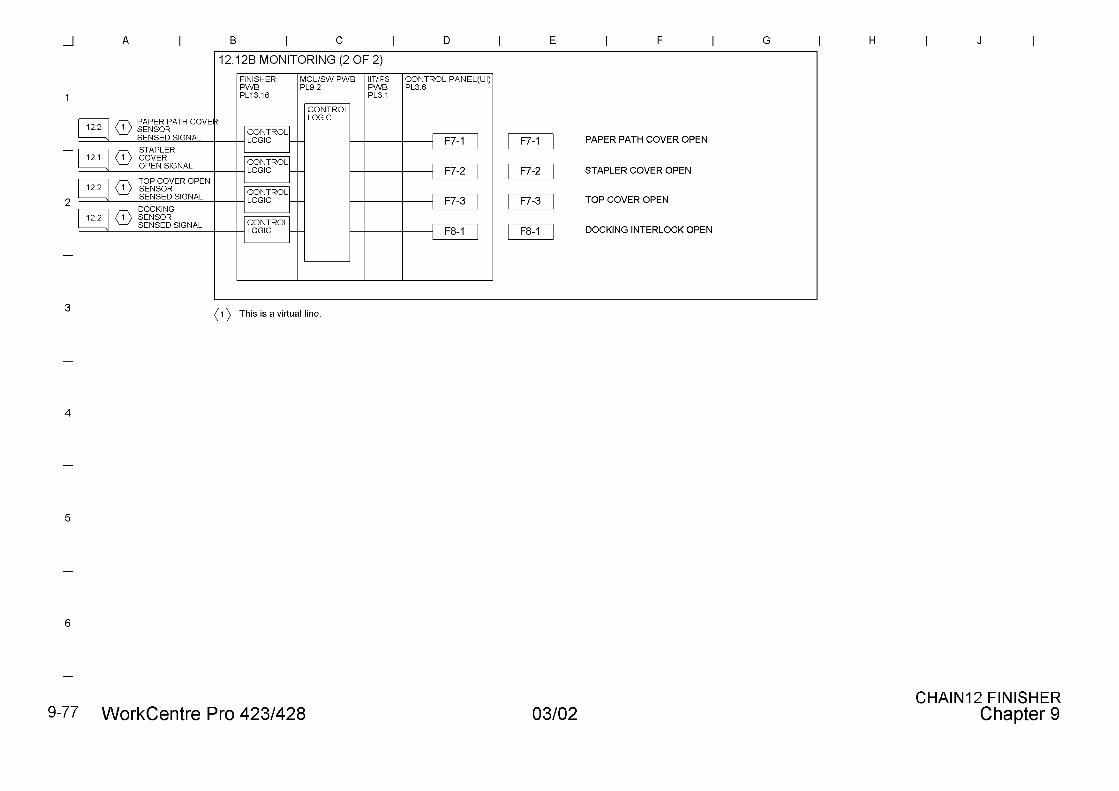
F7-1(4F71)
FINISHERInterlock Open
COMPILER PATH COVER(top) or COMPILER PATHCOVER (lower) is open
Close the COVER. 12.2
F7-2(4F72)
FINISHERInterlock Open
STAPLER COVER is openat COMPILER
Close the Cover. 12.1
F7-3(4F73)
FINISHERInterlock Open
COMPILER TOP COVER isopen
Close the Cover. 12.2
F8-1(4F81)
FINISHERInterlock Open
FIN�SHER Interlock is open Close the Cover. 12.2
J1-2(4B12)
No toner There is no toner. Replace Drum/Cartridge, thenPOWEROFF/ON
9.2
J3-1(4B31)
Drum/Cartridgeinstallationdefect
Drum/Cartridge installationdefect
Extract andinsertDrum/Cartridge
9.1
J6-1(4B61)
CRU life CRU End of life Replace Drum/Cartridge, thenPOWEROFF/ON
9.1
J8-1(4B81)
CRUM AccessError
ID number mismatch Replace Drum/Cartridge, thenPOWEROFF/ON
9.1
J8-3(4B83)
CRUM AccessError
Data read/write error Replace Drum/Cartridge, thenPOWEROFF/ON
9.1
StatusCode
Status Description CorrectiveAction
Ref.BSD
J8-4(4B84)
CRUM AccessError
ACK not received more thanfive times
Replace Drum/Cartridge, thenPOWEROFF/ON
9.1
L6-1(49A1)
No RelatedProduct
Key counter not present Set key counter. 3.2C
03/02 2.3 Level 2 Troubleshooting
WorkCentre Pro 423/428 2-11 CHAPTER 2 TROUBLESHOOTING
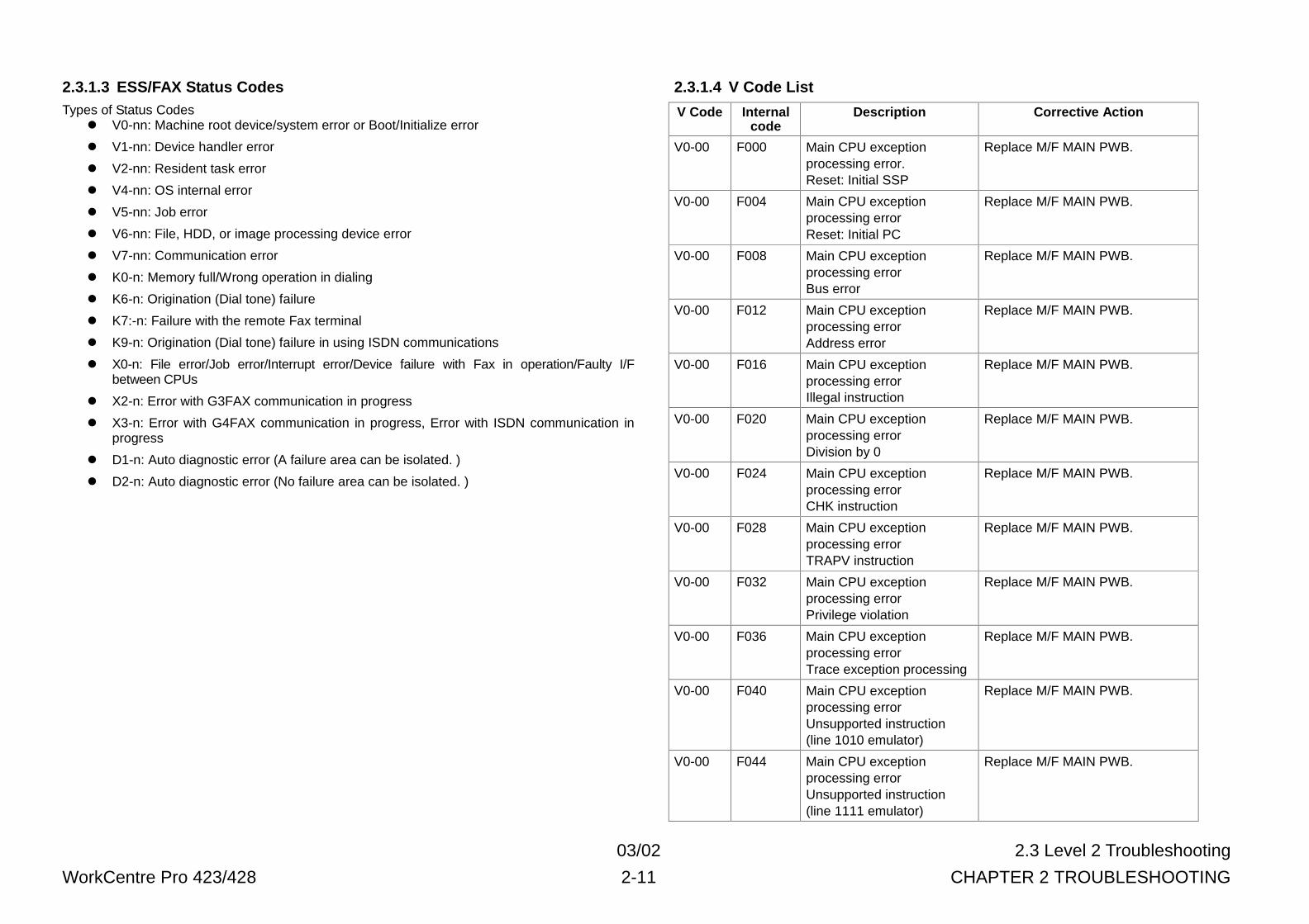
2.3.1.3 ESS/FAX Status CodesTypes of Status Codes
l V0-nn: Machine root device/system error or Boot/Initialize error
l V1-nn: Device handler error
l V2-nn: Resident task error
l V4-nn: OS internal error
l V5-nn: Job error
l V6-nn: File, HDD, or image processing device error
l V7-nn: Communication error
l K0-n: Memory full/Wrong operation in dialing
l K6-n: Origination (Dial tone) failure
l K7:-n: Failure with the remote Fax terminal
l K9-n: Origination (Dial tone) failure in using ISDN communications
l X0-n: File error/Job error/Interrupt error/Device failure with Fax in operation/Faulty I/Fbetween CPUs
l X2-n: Error with G3FAX communication in progress
l X3-n: Error with G4FAX communication in progress, Error with ISDN communication inprogress
l D1-n: Auto diagnostic error (A failure area can be isolated. )
l D2-n: Auto diagnostic error (No failure area can be isolated. )
2.3.1.4 V Code List
V Code Internalcode
Description Corrective Action
V0-00 F000 Main CPU exceptionprocessing error.Reset: Initial SSP
Replace M/F MAIN PWB.
V0-00 F004 Main CPU exceptionprocessing errorReset: Initial PC
Replace M/F MAIN PWB.
V0-00 F008 Main CPU exceptionprocessing errorBus error
Replace M/F MAIN PWB.
V0-00 F012 Main CPU exceptionprocessing errorAddress error
Replace M/F MAIN PWB.
V0-00 F016 Main CPU exceptionprocessing errorIllegal instruction
Replace M/F MAIN PWB.
V0-00 F020 Main CPU exceptionprocessing errorDivision by 0
Replace M/F MAIN PWB.
V0-00 F024 Main CPU exceptionprocessing errorCHK instruction
Replace M/F MAIN PWB.
V0-00 F028 Main CPU exceptionprocessing errorTRAPV instruction
Replace M/F MAIN PWB.
V0-00 F032 Main CPU exceptionprocessing errorPrivilege violation
Replace M/F MAIN PWB.
V0-00 F036 Main CPU exceptionprocessing errorTrace exception processing
Replace M/F MAIN PWB.
V0-00 F040 Main CPU exceptionprocessing errorUnsupported instruction(line 1010 emulator)
Replace M/F MAIN PWB.
V0-00 F044 Main CPU exceptionprocessing errorUnsupported instruction(line 1111 emulator)
Replace M/F MAIN PWB.
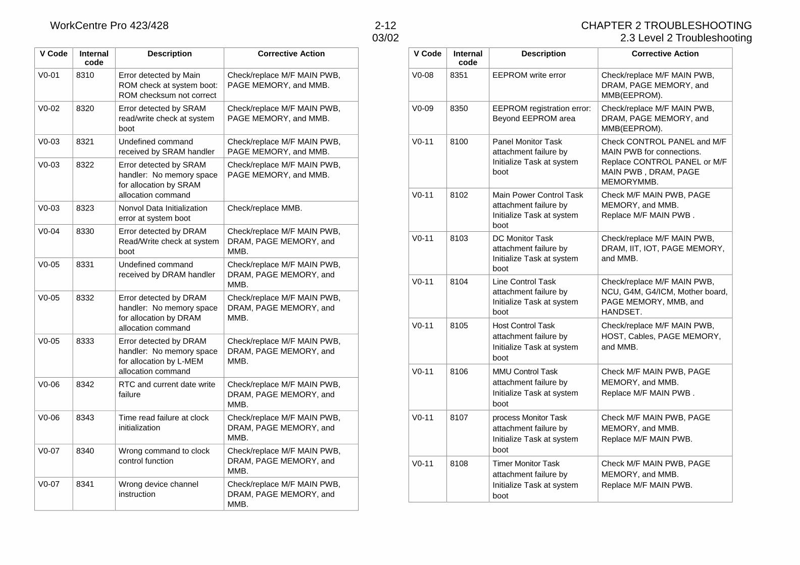
WorkCentre Pro 423/428 2-12 CHAPTER 2 TROUBLESHOOTING03/02 2.3 Level 2 Troubleshooting
V Code Internalcode
Description Corrective Action
V0-01 8310 Error detected by MainROM check at system boot:ROM checksum not correct
Check/replace M/F MAIN PWB,PAGE MEMORY, and MMB.
V0-02 8320 Error detected by SRAMread/write check at systemboot
Check/replace M/F MAIN PWB,PAGE MEMORY, and MMB.
V0-03 8321 Undefined commandreceived by SRAM handler
Check/replace M/F MAIN PWB,PAGE MEMORY, and MMB.
V0-03 8322 Error detected by SRAMhandler: No memory spacefor allocation by SRAMallocation command
Check/replace M/F MAIN PWB,PAGE MEMORY, and MMB.
V0-03 8323 Nonvol Data Initializationerror at system boot
Check/replace MMB.
V0-04 8330 Error detected by DRAMRead/Write check at systemboot
Check/replace M/F MAIN PWB,DRAM, PAGE MEMORY, andMMB.
V0-05 8331 Undefined commandreceived by DRAM handler
Check/replace M/F MAIN PWB,DRAM, PAGE MEMORY, andMMB.
V0-05 8332 Error detected by DRAMhandler: No memory spacefor allocation by DRAMallocation command
Check/replace M/F MAIN PWB,DRAM, PAGE MEMORY, andMMB.
V0-05 8333 Error detected by DRAMhandler: No memory spacefor allocation by L-MEMallocation command
Check/replace M/F MAIN PWB,DRAM, PAGE MEMORY, andMMB.
V0-06 8342 RTC and current date writefailure
Check/replace M/F MAIN PWB,DRAM, PAGE MEMORY, andMMB.
V0-06 8343 Time read failure at clockinitialization
Check/replace M/F MAIN PWB,DRAM, PAGE MEMORY, andMMB.
V0-07 8340 Wrong command to clockcontrol function
Check/replace M/F MAIN PWB,DRAM, PAGE MEMORY, andMMB.
V0-07 8341 Wrong device channelinstruction
Check/replace M/F MAIN PWB,DRAM, PAGE MEMORY, andMMB.
V Code Internalcode
Description Corrective Action
V0-08 8351 EEPROM write error Check/replace M/F MAIN PWB,DRAM, PAGE MEMORY, andMMB(EEPROM).
V0-09 8350 EEPROM registration error:Beyond EEPROM area
Check/replace M/F MAIN PWB,DRAM, PAGE MEMORY, andMMB(EEPROM).
V0-11 8100 Panel Monitor Taskattachment failure byInitialize Task at systemboot
Check CONTROL PANEL and M/FMAIN PWB for connections.Replace CONTROL PANEL or M/FMAIN PWB , DRAM, PAGEMEMORYMMB.
V0-11 8102 Main Power Control Taskattachment failure byInitialize Task at systemboot
Check M/F MAIN PWB, PAGEMEMORY, and MMB.Replace M/F MAIN PWB .
V0-11 8103 DC Monitor Taskattachment failure byInitialize Task at systemboot
Check/replace M/F MAIN PWB,DRAM, IIT, IOT, PAGE MEMORY,and MMB.
V0-11 8104 Line Control Taskattachment failure byInitialize Task at systemboot
Check/replace M/F MAIN PWB,NCU, G4M, G4/ICM, Mother board,PAGE MEMORY, MMB, andHANDSET.
V0-11 8105 Host Control Taskattachment failure byInitialize Task at systemboot
Check/replace M/F MAIN PWB,HOST, Cables, PAGE MEMORY,and MMB.
V0-11 8106 MMU Control Taskattachment failure byInitialize Task at systemboot
Check M/F MAIN PWB, PAGEMEMORY, and MMB.Replace M/F MAIN PWB .
V0-11 8107 process Monitor Taskattachment failure byInitialize Task at systemboot
Check M/F MAIN PWB, PAGEMEMORY, and MMB.Replace M/F MAIN PWB.
V0-11 8108 Timer Monitor Taskattachment failure byInitialize Task at systemboot
Check M/F MAIN PWB, PAGEMEMORY, and MMB.Replace M/F MAIN PWB.
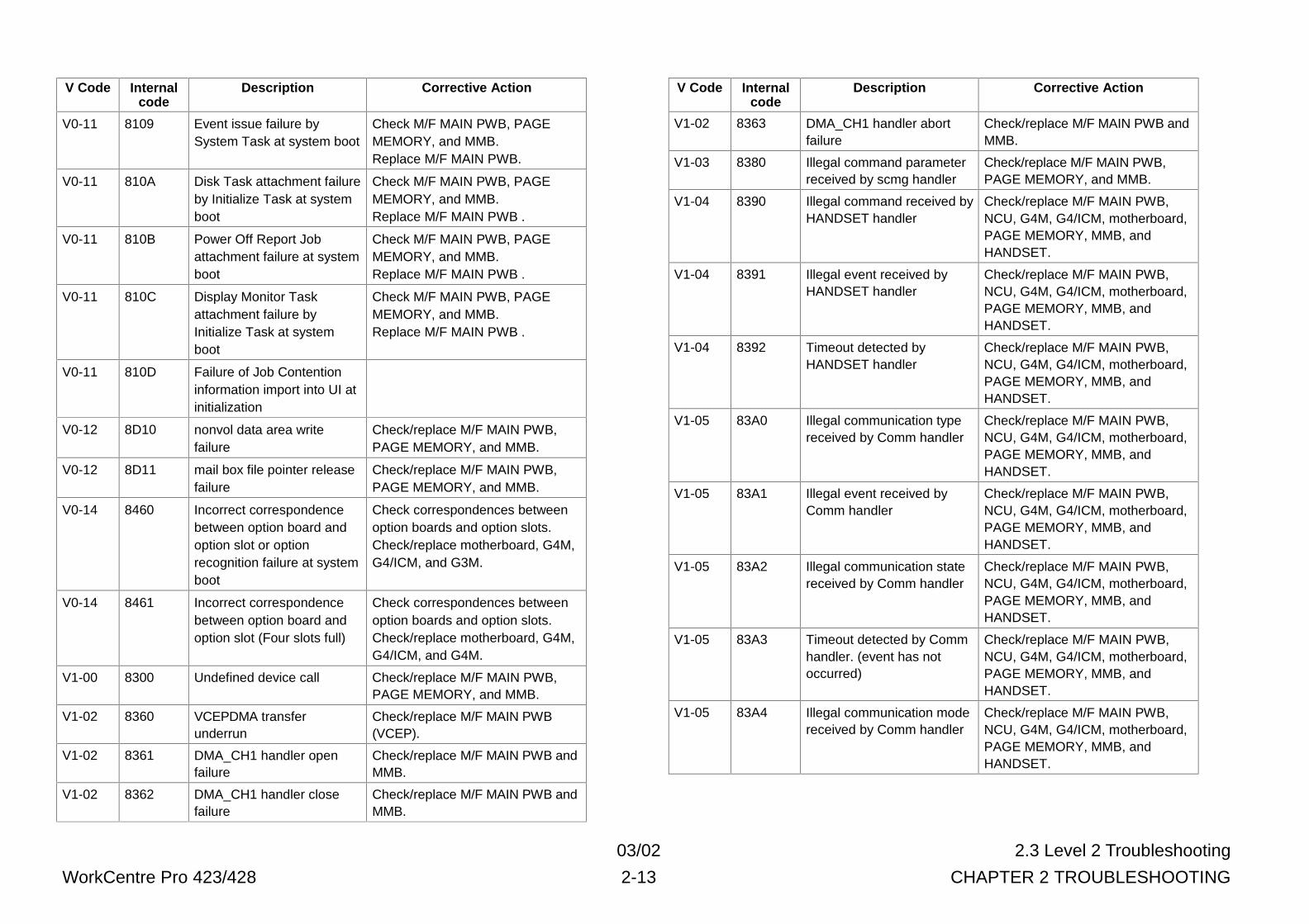
03/02 2.3 Level 2 Troubleshooting
WorkCentre Pro 423/428 2-13 CHAPTER 2 TROUBLESHOOTING
V Code Internalcode
Description Corrective Action
V0-11 8109 Event issue failure bySystem Task at system boot
Check M/F MAIN PWB, PAGEMEMORY, and MMB.Replace M/F MAIN PWB.
V0-11 810A Disk Task attachment failureby Initialize Task at systemboot
Check M/F MAIN PWB, PAGEMEMORY, and MMB.Replace M/F MAIN PWB .
V0-11 810B Power Off Report Jobattachment failure at systemboot
Check M/F MAIN PWB, PAGEMEMORY, and MMB.Replace M/F MAIN PWB .
V0-11 810C Display Monitor Taskattachment failure byInitialize Task at systemboot
Check M/F MAIN PWB, PAGEMEMORY, and MMB.Replace M/F MAIN PWB .
V0-11 810D Failure of Job Contentioninformation import into UI atinitialization
V0-12 8D10 nonvol data area writefailure
Check/replace M/F MAIN PWB,PAGE MEMORY, and MMB.
V0-12 8D11 mail box file pointer releasefailure
Check/replace M/F MAIN PWB,PAGE MEMORY, and MMB.
V0-14 8460 Incorrect correspondencebetween option board andoption slot or optionrecognition failure at systemboot
Check correspondences betweenoption boards and option slots.Check/replace motherboard, G4M,G4/ICM, and G3M.
V0-14 8461 Incorrect correspondencebetween option board andoption slot (Four slots full)
Check correspondences betweenoption boards and option slots.Check/replace motherboard, G4M,G4/ICM, and G4M.
V1-00 8300 Undefined device call Check/replace M/F MAIN PWB,PAGE MEMORY, and MMB.
V1-02 8360 VCEPDMA transferunderrun
Check/replace M/F MAIN PWB(VCEP).
V1-02 8361 DMA_CH1 handler openfailure
Check/replace M/F MAIN PWB andMMB.
V1-02 8362 DMA_CH1 handler closefailure
Check/replace M/F MAIN PWB andMMB.
V Code Internalcode
Description Corrective Action
V1-02 8363 DMA_CH1 handler abortfailure
Check/replace M/F MAIN PWB andMMB.
V1-03 8380 Illegal command parameterreceived by scmg handler
Check/replace M/F MAIN PWB,PAGE MEMORY, and MMB.
V1-04 8390 Illegal command received byHANDSET handler
Check/replace M/F MAIN PWB,NCU, G4M, G4/ICM, motherboard,PAGE MEMORY, MMB, andHANDSET.
V1-04 8391 Illegal event received byHANDSET handler
Check/replace M/F MAIN PWB,NCU, G4M, G4/ICM, motherboard,PAGE MEMORY, MMB, andHANDSET.
V1-04 8392 Timeout detected byHANDSET handler
Check/replace M/F MAIN PWB,NCU, G4M, G4/ICM, motherboard,PAGE MEMORY, MMB, andHANDSET.
V1-05 83A0 Illegal communication typereceived by Comm handler
Check/replace M/F MAIN PWB,NCU, G4M, G4/ICM, motherboard,PAGE MEMORY, MMB, andHANDSET.
V1-05 83A1 Illegal event received byComm handler
Check/replace M/F MAIN PWB,NCU, G4M, G4/ICM, motherboard,PAGE MEMORY, MMB, andHANDSET.
V1-05 83A2 Illegal communication statereceived by Comm handler
Check/replace M/F MAIN PWB,NCU, G4M, G4/ICM, motherboard,PAGE MEMORY, MMB, andHANDSET.
V1-05 83A3 Timeout detected by Commhandler. (event has notoccurred)
Check/replace M/F MAIN PWB,NCU, G4M, G4/ICM, motherboard,PAGE MEMORY, MMB, andHANDSET.
V1-05 83A4 Illegal communication modereceived by Comm handler
Check/replace M/F MAIN PWB,NCU, G4M, G4/ICM, motherboard,PAGE MEMORY, MMB, andHANDSET.
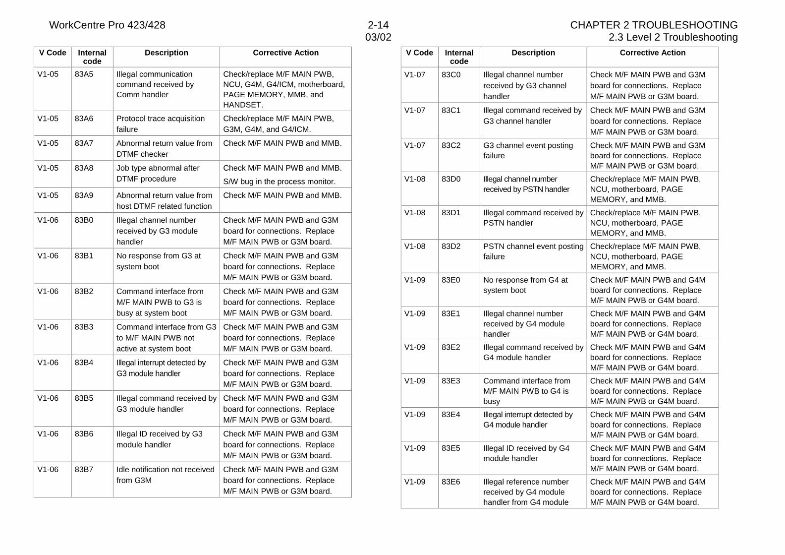
WorkCentre Pro 423/428 2-14 CHAPTER 2 TROUBLESHOOTING03/02 2.3 Level 2 Troubleshooting
V Code Internalcode
Description Corrective Action
V1-05 83A5 Illegal communicationcommand received byComm handler
Check/replace M/F MAIN PWB,NCU, G4M, G4/ICM, motherboard,PAGE MEMORY, MMB, andHANDSET.
V1-05 83A6 Protocol trace acquisitionfailure
Check/replace M/F MAIN PWB,G3M, G4M, and G4/ICM.
V1-05 83A7 Abnormal return value fromDTMF checker
Check M/F MAIN PWB and MMB.
V1-05 83A8 Job type abnormal afterDTMF procedure
Check M/F MAIN PWB and MMB.
S/W bug in the process monitor.
V1-05 83A9 Abnormal return value fromhost DTMF related function
Check M/F MAIN PWB and MMB.
V1-06 83B0 Illegal channel numberreceived by G3 modulehandler
Check M/F MAIN PWB and G3Mboard for connections. ReplaceM/F MAIN PWB or G3M board.
V1-06 83B1 No response from G3 atsystem boot
Check M/F MAIN PWB and G3Mboard for connections. ReplaceM/F MAIN PWB or G3M board.
V1-06 83B2 Command interface fromM/F MAIN PWB to G3 isbusy at system boot
Check M/F MAIN PWB and G3Mboard for connections. ReplaceM/F MAIN PWB or G3M board.
V1-06 83B3 Command interface from G3to M/F MAIN PWB notactive at system boot
Check M/F MAIN PWB and G3Mboard for connections. ReplaceM/F MAIN PWB or G3M board.
V1-06 83B4 Illegal interrupt detected byG3 module handler
Check M/F MAIN PWB and G3Mboard for connections. ReplaceM/F MAIN PWB or G3M board.
V1-06 83B5 Illegal command received byG3 module handler
Check M/F MAIN PWB and G3Mboard for connections. ReplaceM/F MAIN PWB or G3M board.
V1-06 83B6 Illegal ID received by G3module handler
Check M/F MAIN PWB and G3Mboard for connections. ReplaceM/F MAIN PWB or G3M board.
V1-06 83B7 Idle notification not receivedfrom G3M
Check M/F MAIN PWB and G3Mboard for connections. ReplaceM/F MAIN PWB or G3M board.
V Code Internalcode
Description Corrective Action
V1-07 83C0 Illegal channel numberreceived by G3 channelhandler
Check M/F MAIN PWB and G3Mboard for connections. ReplaceM/F MAIN PWB or G3M board.
V1-07 83C1 Illegal command received byG3 channel handler
Check M/F MAIN PWB and G3Mboard for connections. ReplaceM/F MAIN PWB or G3M board.
V1-07 83C2 G3 channel event postingfailure
Check M/F MAIN PWB and G3Mboard for connections. ReplaceM/F MAIN PWB or G3M board.
V1-08 83D0 Illegal channel numberreceived by PSTN handler
Check/replace M/F MAIN PWB,NCU, motherboard, PAGEMEMORY, and MMB.
V1-08 83D1 Illegal command received byPSTN handler
Check/replace M/F MAIN PWB,NCU, motherboard, PAGEMEMORY, and MMB.
V1-08 83D2 PSTN channel event postingfailure
Check/replace M/F MAIN PWB,NCU, motherboard, PAGEMEMORY, and MMB.
V1-09 83E0 No response from G4 atsystem boot
Check M/F MAIN PWB and G4Mboard for connections. ReplaceM/F MAIN PWB or G4M board.
V1-09 83E1 Illegal channel numberreceived by G4 modulehandler
Check M/F MAIN PWB and G4Mboard for connections. ReplaceM/F MAIN PWB or G4M board.
V1-09 83E2 Illegal command received byG4 module handler
Check M/F MAIN PWB and G4Mboard for connections. ReplaceM/F MAIN PWB or G4M board.
V1-09 83E3 Command interface fromM/F MAIN PWB to G4 isbusy
Check M/F MAIN PWB and G4Mboard for connections. ReplaceM/F MAIN PWB or G4M board.
V1-09 83E4 Illegal interrupt detected byG4 module handler
Check M/F MAIN PWB and G4Mboard for connections. ReplaceM/F MAIN PWB or G4M board.
V1-09 83E5 Illegal ID received by G4module handler
Check M/F MAIN PWB and G4Mboard for connections. ReplaceM/F MAIN PWB or G4M board.
V1-09 83E6 Illegal reference numberreceived by G4 modulehandler from G4 module
Check M/F MAIN PWB and G4Mboard for connections. ReplaceM/F MAIN PWB or G4M board.
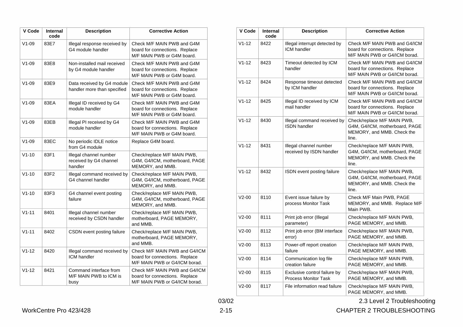
03/02 2.3 Level 2 Troubleshooting
WorkCentre Pro 423/428 2-15 CHAPTER 2 TROUBLESHOOTING
V Code Internalcode
Description Corrective Action
V1-09 83E7 Illegal response received byG4 module handler
Check M/F MAIN PWB and G4Mboard for connections. ReplaceM/F MAIN PWB or G4M board.
V1-09 83E8 Non-installed mail receivedby G4 module handler
Check M/F MAIN PWB and G4Mboard for connections. ReplaceM/F MAIN PWB or G4M board.
V1-09 83E9 Data received by G4 modulehandler more than specified
Check M/F MAIN PWB and G4Mboard for connections. ReplaceM/F MAIN PWB or G4M board.
V1-09 83EA Illegal ID received by G4module handler
Check M/F MAIN PWB and G4Mboard for connections. ReplaceM/F MAIN PWB or G4M board.
V1-09 83EB Illegal PI received by G4module handler
Check M/F MAIN PWB and G4Mboard for connections. ReplaceM/F MAIN PWB or G4M board.
V1-09 83EC No periodic IDLE noticefrom G4 module
Replace G4M board.
V1-10 83F1 Illegal channel numberreceived by G4 channelhandler
Check/replace M/F MAIN PWB,G4M, G4/ICM, motherboard, PAGEMEMORY, and MMB.
V1-10 83F2 Illegal command received byG4 channel handler
Check/replace M/F MAIN PWB,G4M, G4/ICM, motherboard, PAGEMEMORY, and MMB.
V1-10 83F3 G4 channel event postingfailure
Check/replace M/F MAIN PWB,G4M, G4/ICM, motherboard, PAGEMEMORY, and MMB.
V1-11 8401 Illegal channel numberreceived by CSDN handler
Check/replace M/F MAIN PWB,motherboard, PAGE MEMORY,and MMB.
V1-11 8402 CSDN event posting failure Check/replace M/F MAIN PWB,motherboard, PAGE MEMORY,and MMB.
V1-12 8420 Illegal command received byICM handler
Check M/F MAIN PWB and G4/ICMboard for connections. ReplaceM/F MAIN PWB or G4/ICM borad.
V1-12 8421 Command interface fromM/F MAIN PWB to ICM isbusy
Check M/F MAIN PWB and G4/ICMboard for connections. ReplaceM/F MAIN PWB or G4/ICM borad.
V Code Internalcode
Description Corrective Action
V1-12 8422 Illegal interrupt detected byICM handler
Check M/F MAIN PWB and G4/ICMboard for connections. ReplaceM/F MAIN PWB or G4/ICM borad.
V1-12 8423 Timeout detected by ICMhandler
Check M/F MAIN PWB and G4/ICMboard for connections. ReplaceM/F MAIN PWB or G4/ICM borad.
V1-12 8424 Response timeout detectedby ICM handler
Check M/F MAIN PWB and G4/ICMboard for connections. ReplaceM/F MAIN PWB or G4/ICM borad.
V1-12 8425 Illegal ID received by ICMmail handler
Check M/F MAIN PWB and G4/ICMboard for connections. ReplaceM/F MAIN PWB or G4/ICM borad.
V1-12 8430 Illegal command received byISDN handler
Check/replace M/F MAIN PWB,G4M, G4/ICM, motherboard, PAGEMEMORY, and MMB. Check theline.
V1-12 8431 Illegal channel numberreceived by ISDN handler
Check/replace M/F MAIN PWB,G4M, G4/ICM, motherboard, PAGEMEMORY, and MMB. Check theline.
V1-12 8432 ISDN event posting failure Check/replace M/F MAIN PWB,G4M, G4/ICM, motherboard, PAGEMEMORY, and MMB. Check theline.
V2-00 8110 Event issue failure byprocess Monitor Task
Check M/F Main PWB, PAGEMEMORY, and MMB. Replace M/FMain PWB.
V2-00 8111 Print job error (Illegalparameter)
Check/replace M/F MAIN PWB,PAGE MEMORY, and MMB.
V2-00 8112 Print job error (BM interfaceerror)
Check/replace M/F MAIN PWB,PAGE MEMORY, and MMB.
V2-00 8113 Power-off report creationfailure
Check/replace M/F MAIN PWB,PAGE MEMORY, and MMB.
V2-00 8114 Communication log filecreation failure
Check/replace M/F MAIN PWB,PAGE MEMORY, and MMB.
V2-00 8115 Exclusive control failure byProcess Monitor Task
Check/replace M/F MAIN PWB,PAGE MEMORY, and MMB.
V2-00 8117 File information read failure Check/replace M/F MAIN PWB,PAGE MEMORY, and MMB.
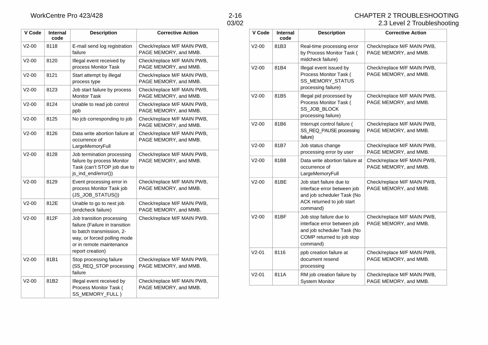
WorkCentre Pro 423/428 2-16 CHAPTER 2 TROUBLESHOOTING03/02 2.3 Level 2 Troubleshooting
V Code Internalcode
Description Corrective Action
V2-00 8118 E-mail send log registrationfailure
Check/replace M/F MAIN PWB,PAGE MEMORY, and MMB.
V2-00 8120 Illegal event received byprocess Monitor Task
Check/replace M/F MAIN PWB,PAGE MEMORY, and MMB.
V2-00 8121 Start attempt by illegalprocess type
Check/replace M/F MAIN PWB,PAGE MEMORY, and MMB.
V2-00 8123 Job start failure by processMonitor Task
Check/replace M/F MAIN PWB,PAGE MEMORY, and MMB.
V2-00 8124 Unable to read job controlppb
Check/replace M/F MAIN PWB,PAGE MEMORY, and MMB.
V2-00 8125 No jcb corresponding to job Check/replace M/F MAIN PWB,PAGE MEMORY, and MMB.
V2-00 8126 Data write abortion failure atoccurrence ofLargeMemoryFull
Check/replace M/F MAIN PWB,PAGE MEMORY, and MMB.
V2-00 8128 Job termination processingfailure by process MonitorTask (can’t STOP job due tojs_ind_end/error())
Check/replace M/F MAIN PWB,PAGE MEMORY, and MMB.
V2-00 8129 Event processing error inprocess Monitor Task job(JS_JOB_STATUS())
Check/replace M/F MAIN PWB,PAGE MEMORY, and MMB.
V2-00 812E Unable to go to next job(endcheck failure)
Check/replace M/F MAIN PWB,PAGE MEMORY, and MMB.
V2-00 812F Job transition processingfailure (Failure in transitionto batch transmission, 2-way, or forced polling modeor in remote maintenancereport creation)
Check/replace M/F MAIN PWB.
V2-00 81B1 Stop processing failure(SS_REQ_STOP processingfailure
Check/replace M/F MAIN PWB,PAGE MEMORY, and MMB.
V2-00 81B2 Illegal event received byProcess Monitor Task (SS_MEMORY_FULL )
Check/replace M/F MAIN PWB,PAGE MEMORY, and MMB.
V Code Internalcode
Description Corrective Action
V2-00 81B3 Real-time processing errorby Process Monitor Task (midcheck failure)
Check/replace M/F MAIN PWB,PAGE MEMORY, and MMB.
V2-00 81B4 Illegal event issued byProcess Monitor Task (SS_MEMORY_STATUSprocessing failure)
Check/replace M/F MAIN PWB,PAGE MEMORY, and MMB.
V2-00 81B5 Illegal pid processed byProcess Monitor Task (SS_JOB_BLOCKprocessing failure)
Check/replace M/F MAIN PWB,PAGE MEMORY, and MMB.
V2-00 81B6 Interrupt control failure (SS_REQ_PAUSE processingfailure)
Check/replace M/F MAIN PWB,PAGE MEMORY, and MMB.
V2-00 81B7 Job status changeprocessing error by user
Check/replace M/F MAIN PWB,PAGE MEMORY, and MMB.
V2-00 81B8 Data write abortion failure atoccurrence ofLargeMemoryFull
Check/replace M/F MAIN PWB,PAGE MEMORY, and MMB.
V2-00 81BE Job start failure due tointerface error between joband job scheduler Task (NoACK returned to job startcommand)
Check/replace M/F MAIN PWB,PAGE MEMORY, and MMB.
V2-00 81BF Job stop failure due tointerface error between joband job scheduler Task (NoCOMP returned to job stopcommand)
Check/replace M/F MAIN PWB,PAGE MEMORY, and MMB.
V2-01 8116 ppb creation failure atdocument resendprocessing
Check/replace M/F MAIN PWB,PAGE MEMORY, and MMB.
V2-01 811A RM job creation failure bySystem Monitor
Check/replace M/F MAIN PWB,PAGE MEMORY, and MMB.
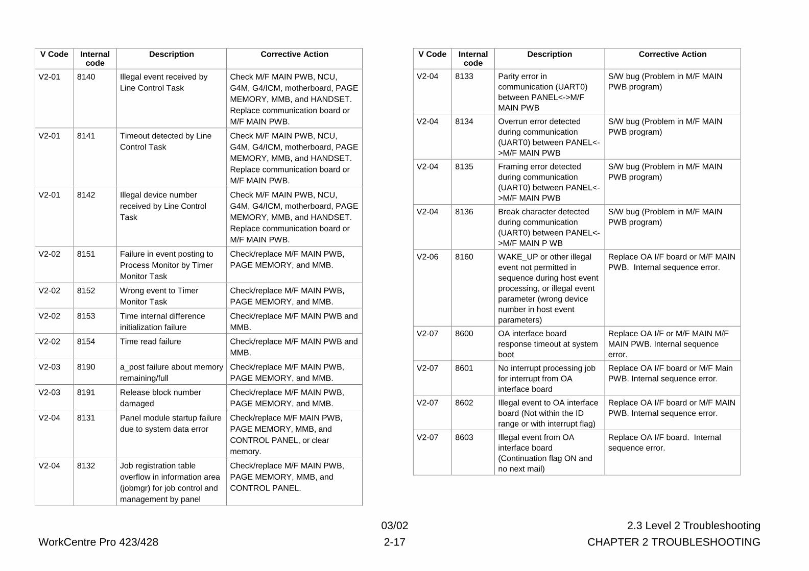
03/02 2.3 Level 2 Troubleshooting
WorkCentre Pro 423/428 2-17 CHAPTER 2 TROUBLESHOOTING
V Code Internalcode
Description Corrective Action
V2-01 8140 Illegal event received byLine Control Task
Check M/F MAIN PWB, NCU,G4M, G4/ICM, motherboard, PAGEMEMORY, MMB, and HANDSET.Replace communication board orM/F MAIN PWB.
V2-01 8141 Timeout detected by LineControl Task
Check M/F MAIN PWB, NCU,G4M, G4/ICM, motherboard, PAGEMEMORY, MMB, and HANDSET.Replace communication board orM/F MAIN PWB.
V2-01 8142 Illegal device numberreceived by Line ControlTask
Check M/F MAIN PWB, NCU,G4M, G4/ICM, motherboard, PAGEMEMORY, MMB, and HANDSET.Replace communication board orM/F MAIN PWB.
V2-02 8151 Failure in event posting toProcess Monitor by TimerMonitor Task
Check/replace M/F MAIN PWB,PAGE MEMORY, and MMB.
V2-02 8152 Wrong event to TimerMonitor Task
Check/replace M/F MAIN PWB,PAGE MEMORY, and MMB.
V2-02 8153 Time internal differenceinitialization failure
Check/replace M/F MAIN PWB andMMB.
V2-02 8154 Time read failure Check/replace M/F MAIN PWB andMMB.
V2-03 8190 a_post failure about memoryremaining/full
Check/replace M/F MAIN PWB,PAGE MEMORY, and MMB.
V2-03 8191 Release block numberdamaged
Check/replace M/F MAIN PWB,PAGE MEMORY, and MMB.
V2-04 8131 Panel module startup failuredue to system data error
Check/replace M/F MAIN PWB,PAGE MEMORY, MMB, andCONTROL PANEL, or clearmemory.
V2-04 8132 Job registration tableoverflow in information area(jobmgr) for job control andmanagement by panel
Check/replace M/F MAIN PWB,PAGE MEMORY, MMB, andCONTROL PANEL.
V Code Internalcode
Description Corrective Action
V2-04 8133 Parity error incommunication (UART0)between PANEL<->M/FMAIN PWB
S/W bug (Problem in M/F MAINPWB program)
V2-04 8134 Overrun error detectedduring communication(UART0) between PANEL<->M/F MAIN PWB
S/W bug (Problem in M/F MAINPWB program)
V2-04 8135 Framing error detectedduring communication(UART0) between PANEL<->M/F MAIN PWB
S/W bug (Problem in M/F MAINPWB program)
V2-04 8136 Break character detectedduring communication(UART0) between PANEL<->M/F MAIN P WB
S/W bug (Problem in M/F MAINPWB program)
V2-06 8160 WAKE_UP or other illegalevent not permitted insequence during host eventprocessing, or illegal eventparameter (wrong devicenumber in host eventparameters)
Replace OA I/F board or M/F MAINPWB. Internal sequence error.
V2-07 8600 OA interface boardresponse timeout at systemboot
Replace OA I/F or M/F MAIN M/FMAIN PWB. Internal sequenceerror.
V2-07 8601 No interrupt processing jobfor interrupt from OAinterface board
Replace OA I/F board or M/F MainPWB. Internal sequence error.
V2-07 8602 Illegal event to OA interfaceboard (Not within the IDrange or with interrupt flag)
Replace OA I/F board or M/F MAINPWB. Internal sequence error.
V2-07 8603 Illegal event from OAinterface board(Continuation flag ON andno next mail)
Replace OA I/F board. Internalsequence error.
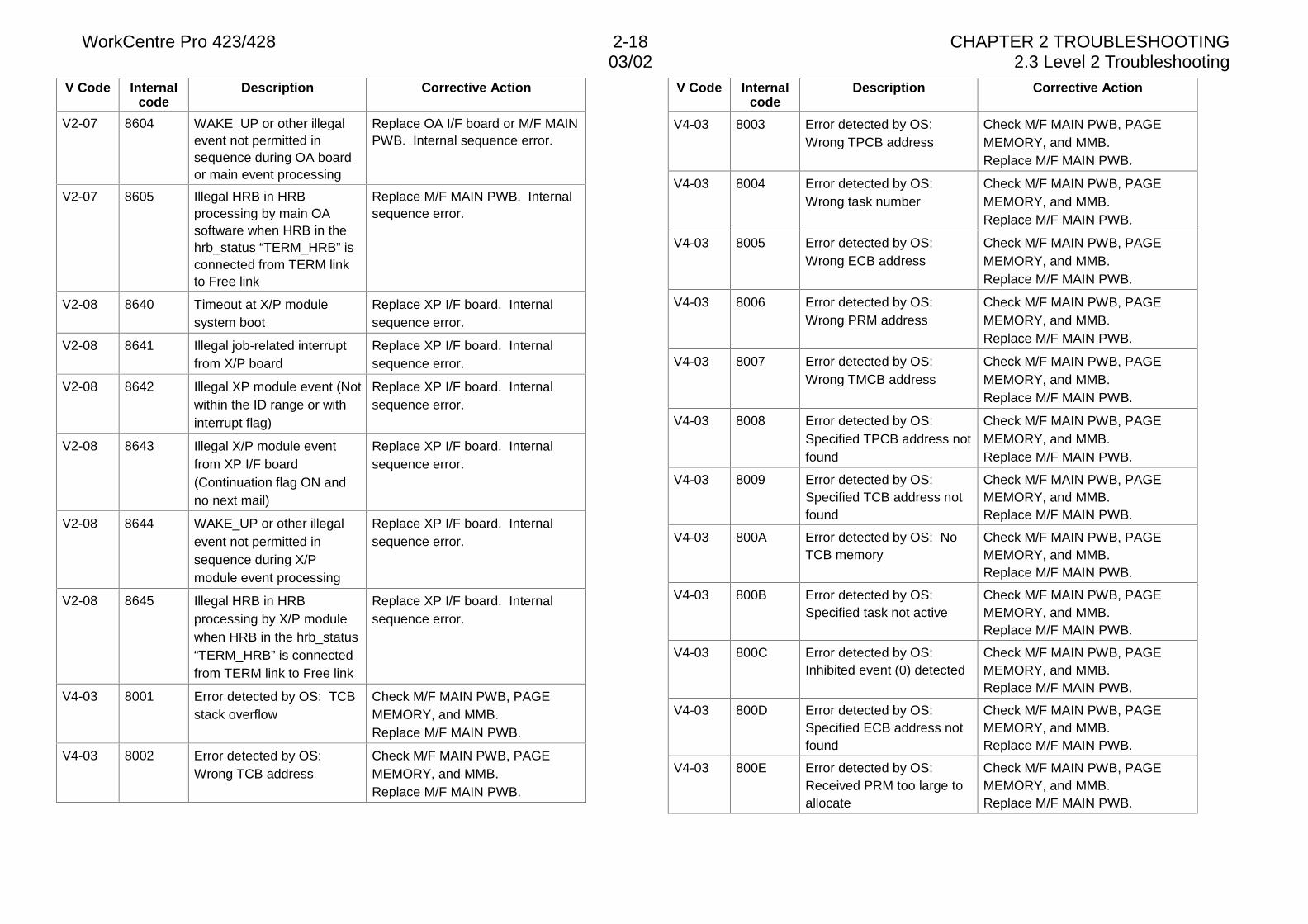
WorkCentre Pro 423/428 2-18 CHAPTER 2 TROUBLESHOOTING03/02 2.3 Level 2 Troubleshooting
V Code Internalcode
Description Corrective Action
V2-07 8604 WAKE_UP or other illegalevent not permitted insequence during OA boardor main event processing
Replace OA I/F board or M/F MAINPWB. Internal sequence error.
V2-07 8605 Illegal HRB in HRBprocessing by main OAsoftware when HRB in thehrb_status “TERM_HRB” isconnected from TERM linkto Free link
Replace M/F MAIN PWB. Internalsequence error.
V2-08 8640 Timeout at X/P modulesystem boot
Replace XP I/F board. Internalsequence error.
V2-08 8641 Illegal job-related interruptfrom X/P board
Replace XP I/F board. Internalsequence error.
V2-08 8642 Illegal XP module event (Notwithin the ID range or withinterrupt flag)
Replace XP I/F board. Internalsequence error.
V2-08 8643 Illegal X/P module eventfrom XP I/F board(Continuation flag ON andno next mail)
Replace XP I/F board. Internalsequence error.
V2-08 8644 WAKE_UP or other illegalevent not permitted insequence during X/Pmodule event processing
Replace XP I/F board. Internalsequence error.
V2-08 8645 Illegal HRB in HRBprocessing by X/P modulewhen HRB in the hrb_status“TERM_HRB” is connectedfrom TERM link to Free link
Replace XP I/F board. Internalsequence error.
V4-03 8001 Error detected by OS: TCBstack overflow
Check M/F MAIN PWB, PAGEMEMORY, and MMB.Replace M/F MAIN PWB.
V4-03 8002 Error detected by OS:Wrong TCB address
Check M/F MAIN PWB, PAGEMEMORY, and MMB.Replace M/F MAIN PWB.
V Code Internalcode
Description Corrective Action
V4-03 8003 Error detected by OS:Wrong TPCB address
Check M/F MAIN PWB, PAGEMEMORY, and MMB.Replace M/F MAIN PWB.
V4-03 8004 Error detected by OS:Wrong task number
Check M/F MAIN PWB, PAGEMEMORY, and MMB.Replace M/F MAIN PWB.
V4-03 8005 Error detected by OS:Wrong ECB address
Check M/F MAIN PWB, PAGEMEMORY, and MMB.Replace M/F MAIN PWB.
V4-03 8006 Error detected by OS:Wrong PRM address
Check M/F MAIN PWB, PAGEMEMORY, and MMB.Replace M/F MAIN PWB.
V4-03 8007 Error detected by OS:Wrong TMCB address
Check M/F MAIN PWB, PAGEMEMORY, and MMB.Replace M/F MAIN PWB.
V4-03 8008 Error detected by OS:Specified TPCB address notfound
Check M/F MAIN PWB, PAGEMEMORY, and MMB.Replace M/F MAIN PWB.
V4-03 8009 Error detected by OS:Specified TCB address notfound
Check M/F MAIN PWB, PAGEMEMORY, and MMB.Replace M/F MAIN PWB.
V4-03 800A Error detected by OS: NoTCB memory
Check M/F MAIN PWB, PAGEMEMORY, and MMB.Replace M/F MAIN PWB.
V4-03 800B Error detected by OS:Specified task not active
Check M/F MAIN PWB, PAGEMEMORY, and MMB.Replace M/F MAIN PWB.
V4-03 800C Error detected by OS:Inhibited event (0) detected
Check M/F MAIN PWB, PAGEMEMORY, and MMB.Replace M/F MAIN PWB.
V4-03 800D Error detected by OS:Specified ECB address notfound
Check M/F MAIN PWB, PAGEMEMORY, and MMB.Replace M/F MAIN PWB.
V4-03 800E Error detected by OS:Received PRM too large toallocate
Check M/F MAIN PWB, PAGEMEMORY, and MMB.Replace M/F MAIN PWB.
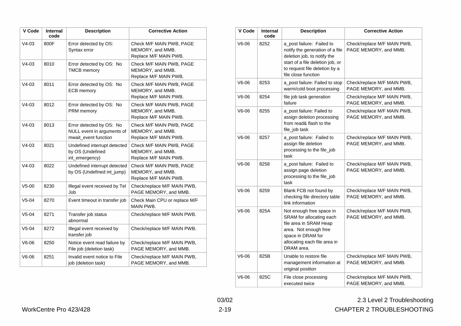
03/02 2.3 Level 2 Troubleshooting
WorkCentre Pro 423/428 2-19 CHAPTER 2 TROUBLESHOOTING
V Code Internalcode
Description Corrective Action
V4-03 800F Error detected by OS:Syntax error
Check M/F MAIN PWB, PAGEMEMORY, and MMB.Replace M/F MAIN PWB.
V4-03 8010 Error detected by OS: NoTMCB memory
Check M/F MAIN PWB, PAGEMEMORY, and MMB.Replace M/F MAIN PWB.
V4-03 8011 Error detected by OS: NoECB memory
Check M/F MAIN PWB, PAGEMEMORY, and MMB.Replace M/F MAIN PWB.
V4-03 8012 Error detected by OS: NoPRM memory
Check M/F MAIN PWB, PAGEMEMORY, and MMB.Replace M/F MAIN PWB.
V4-03 8013 Error detected by OS: NoNULL event in arguments ofmwait_event function
Check M/F MAIN PWB, PAGEMEMORY, and MMB.Replace M/F MAIN PWB.
V4-03 8021 Undefined interrupt detectedby OS (Undefinedint_emergency)
Check M/F MAIN PWB, PAGEMEMORY, and MMB.Replace M/F MAIN PWB.
V4-03 8022 Undefined interrupt detectedby OS (Undefined int_jump)
Check M/F MAIN PWB, PAGEMEMORY, and MMB.Replace M/F MAIN PWB.
V5-00 8230 Illegal event received by TelJob
Check/replace M/F MAIN PWB,PAGE MEMORY, and MMB.
V5-04 8270 Event timeout in transfer job Check Main CPU or replace M/FMAIN PWB.
V5-04 8271 Transfer job statusabnormal
Check/replace M/F MAIN PWB.
V5-04 8272 Illegal event received bytransfer job
Check/replace M/F MAIN PWB.
V6-06 8250 Notice event read failure byFile job (deletion task)
Check/replace M/F MAIN PWB,PAGE MEMORY, and MMB.
V6-06 8251 Invalid event notice to Filejob (deletion task)
Check/replace M/F MAIN PWB,PAGE MEMORY, and MMB.
V Code Internalcode
Description Corrective Action
V6-06 8252 a_post failure: Failed tonotify the generation of a filedeletion job, to notify thestart of a file deletion job, orto request file deletion by afile close function
Check/replace M/F MAIN PWB,PAGE MEMORY, and MMB.
V6-06 8253 a_post failure: Failed to stopwarm/cold boot processing
Check/replace M/F MAIN PWB,PAGE MEMORY, and MMB.
V6-06 8254 file job task generationfailure
Check/replace M/F MAIN PWB,PAGE MEMORY, and MMB.
V6-06 8255 a_post failure: Failed toassign deletion processingfrom read& flash to thefile_job task
Check/replace M/F MAIN PWB,PAGE MEMORY, and MMB.
V6-06 8257 a_post failure: Failed toassign file deletionprocessing to the file_jobtask
Check/replace M/F MAIN PWB,PAGE MEMORY, and MMB.
V6-06 8258 a_post failure: Failed toassign page deletionprocessing to the file_jobtask
Check/replace M/F MAIN PWB,PAGE MEMORY, and MMB.
V6-06 8259 Blank FCB not found bychecking file directory tablelink information
Check/replace M/F MAIN PWB,PAGE MEMORY, and MMB.
V6-06 825A Not enough free space inSRAM for allocating eachfile area in SRAM Heaparea. Not enough freespace in DRAM forallocating each file area inDRAM area.
Check/replace M/F MAIN PWB,PAGE MEMORY, and MMB.
V6-06 825B Unable to restore filemanagement information atoriginal position
Check/replace M/F MAIN PWB,PAGE MEMORY, and MMB.
V6-06 825C File close processingexecuted twice
Check/replace M/F MAIN PWB,PAGE MEMORY, and MMB.
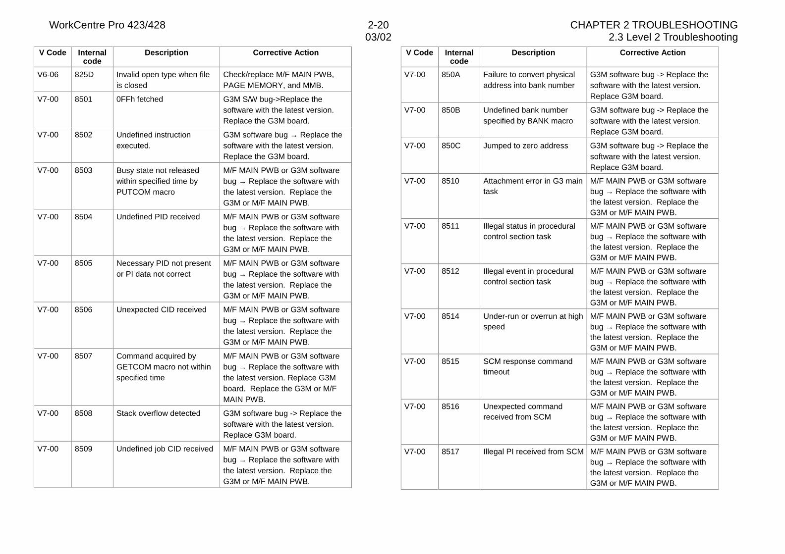
WorkCentre Pro 423/428 2-20 CHAPTER 2 TROUBLESHOOTING03/02 2.3 Level 2 Troubleshooting
V Code Internalcode
Description Corrective Action
V6-06 825D Invalid open type when fileis closed
Check/replace M/F MAIN PWB,PAGE MEMORY, and MMB.
V7-00 8501 0FFh fetched G3M S/W bug->Replace thesoftware with the latest version.Replace the G3M board.
V7-00 8502 Undefined instructionexecuted.
G3M software bug → Replace thesoftware with the latest version.Replace the G3M board.
V7-00 8503 Busy state not releasedwithin specified time byPUTCOM macro
M/F MAIN PWB or G3M softwarebug → Replace the software withthe latest version. Replace theG3M or M/F MAIN PWB.
V7-00 8504 Undefined PID received M/F MAIN PWB or G3M softwarebug → Replace the software withthe latest version. Replace theG3M or M/F MAIN PWB.
V7-00 8505 Necessary PID not presentor PI data not correct
M/F MAIN PWB or G3M softwarebug → Replace the software withthe latest version. Replace theG3M or M/F MAIN PWB.
V7-00 8506 Unexpected CID received M/F MAIN PWB or G3M softwarebug → Replace the software withthe latest version. Replace theG3M or M/F MAIN PWB.
V7-00 8507 Command acquired byGETCOM macro not withinspecified time
M/F MAIN PWB or G3M softwarebug → Replace the software withthe latest version. Replace G3Mboard. Replace the G3M or M/FMAIN PWB.
V7-00 8508 Stack overflow detected G3M software bug -> Replace thesoftware with the latest version.Replace G3M board.
V7-00 8509 Undefined job CID received M/F MAIN PWB or G3M softwarebug → Replace the software withthe latest version. Replace theG3M or M/F MAIN PWB.
V Code Internalcode
Description Corrective Action
V7-00 850A Failure to convert physicaladdress into bank number
G3M software bug -> Replace thesoftware with the latest version.Replace G3M board.
V7-00 850B Undefined bank numberspecified by BANK macro
G3M software bug -> Replace thesoftware with the latest version.Replace G3M board.
V7-00 850C Jumped to zero address G3M software bug -> Replace thesoftware with the latest version.Replace G3M board.
V7-00 8510 Attachment error in G3 maintask
M/F MAIN PWB or G3M softwarebug → Replace the software withthe latest version. Replace theG3M or M/F MAIN PWB.
V7-00 8511 Illegal status in proceduralcontrol section task
M/F MAIN PWB or G3M softwarebug → Replace the software withthe latest version. Replace theG3M or M/F MAIN PWB.
V7-00 8512 Illegal event in proceduralcontrol section task
M/F MAIN PWB or G3M softwarebug → Replace the software withthe latest version. Replace theG3M or M/F MAIN PWB.
V7-00 8514 Under-run or overrun at highspeed
M/F MAIN PWB or G3M softwarebug → Replace the software withthe latest version. Replace theG3M or M/F MAIN PWB.
V7-00 8515 SCM response commandtimeout
M/F MAIN PWB or G3M softwarebug → Replace the software withthe latest version. Replace theG3M or M/F MAIN PWB.
V7-00 8516 Unexpected commandreceived from SCM
M/F MAIN PWB or G3M softwarebug → Replace the software withthe latest version. Replace theG3M or M/F MAIN PWB.
V7-00 8517 Illegal PI received from SCM M/F MAIN PWB or G3M softwarebug → Replace the software withthe latest version. Replace theG3M or M/F MAIN PWB.
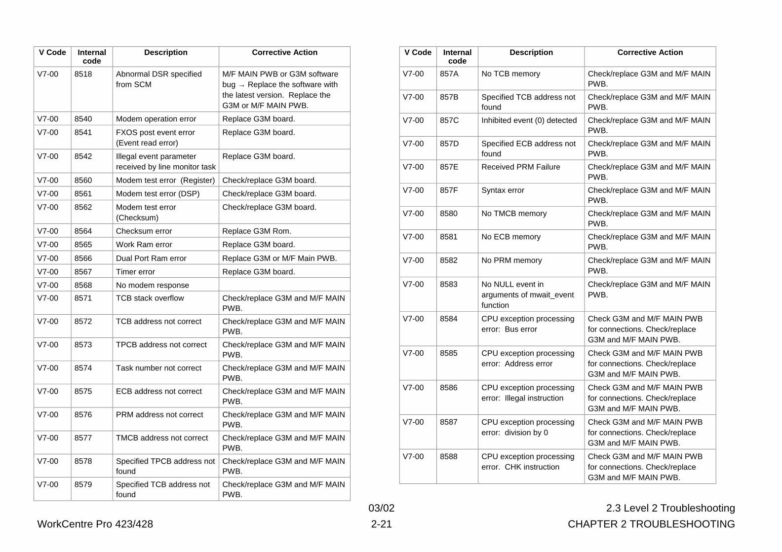
03/02 2.3 Level 2 Troubleshooting
WorkCentre Pro 423/428 2-21 CHAPTER 2 TROUBLESHOOTING
V Code Internalcode
Description Corrective Action
V7-00 8518 Abnormal DSR specifiedfrom SCM
M/F MAIN PWB or G3M softwarebug → Replace the software withthe latest version. Replace theG3M or M/F MAIN PWB.
V7-00 8540 Modem operation error Replace G3M board.
V7-00 8541 FXOS post event error(Event read error)
Replace G3M board.
V7-00 8542 Illegal event parameterreceived by line monitor task
Replace G3M board.
V7-00 8560 Modem test error (Register) Check/replace G3M board.
V7-00 8561 Modem test error (DSP) Check/replace G3M board.
V7-00 8562 Modem test error(Checksum)
Check/replace G3M board.
V7-00 8564 Checksum error Replace G3M Rom.
V7-00 8565 Work Ram error Replace G3M board.
V7-00 8566 Dual Port Ram error Replace G3M or M/F Main PWB.
V7-00 8567 Timer error Replace G3M board.
V7-00 8568 No modem response
V7-00 8571 TCB stack overflow Check/replace G3M and M/F MAINPWB.
V7-00 8572 TCB address not correct Check/replace G3M and M/F MAINPWB.
V7-00 8573 TPCB address not correct Check/replace G3M and M/F MAINPWB.
V7-00 8574 Task number not correct Check/replace G3M and M/F MAINPWB.
V7-00 8575 ECB address not correct Check/replace G3M and M/F MAINPWB.
V7-00 8576 PRM address not correct Check/replace G3M and M/F MAINPWB.
V7-00 8577 TMCB address not correct Check/replace G3M and M/F MAINPWB.
V7-00 8578 Specified TPCB address notfound
Check/replace G3M and M/F MAINPWB.
V7-00 8579 Specified TCB address notfound
Check/replace G3M and M/F MAINPWB.
V Code Internalcode
Description Corrective Action
V7-00 857A No TCB memory Check/replace G3M and M/F MAINPWB.
V7-00 857B Specified TCB address notfound
Check/replace G3M and M/F MAINPWB.
V7-00 857C Inhibited event (0) detected Check/replace G3M and M/F MAINPWB.
V7-00 857D Specified ECB address notfound
Check/replace G3M and M/F MAINPWB.
V7-00 857E Received PRM Failure Check/replace G3M and M/F MAINPWB.
V7-00 857F Syntax error Check/replace G3M and M/F MAINPWB.
V7-00 8580 No TMCB memory Check/replace G3M and M/F MAINPWB.
V7-00 8581 No ECB memory Check/replace G3M and M/F MAINPWB.
V7-00 8582 No PRM memory Check/replace G3M and M/F MAINPWB.
V7-00 8583 No NULL event inarguments of mwait_eventfunction
Check/replace G3M and M/F MAINPWB.
V7-00 8584 CPU exception processingerror: Bus error
Check G3M and M/F MAIN PWBfor connections. Check/replaceG3M and M/F MAIN PWB.
V7-00 8585 CPU exception processingerror: Address error
Check G3M and M/F MAIN PWBfor connections. Check/replaceG3M and M/F MAIN PWB.
V7-00 8586 CPU exception processingerror: Illegal instruction
Check G3M and M/F MAIN PWBfor connections. Check/replaceG3M and M/F MAIN PWB.
V7-00 8587 CPU exception processingerror: division by 0
Check G3M and M/F MAIN PWBfor connections. Check/replaceG3M and M/F MAIN PWB.
V7-00 8588 CPU exception processingerror. CHK instruction
Check G3M and M/F MAIN PWBfor connections. Check/replaceG3M and M/F MAIN PWB.
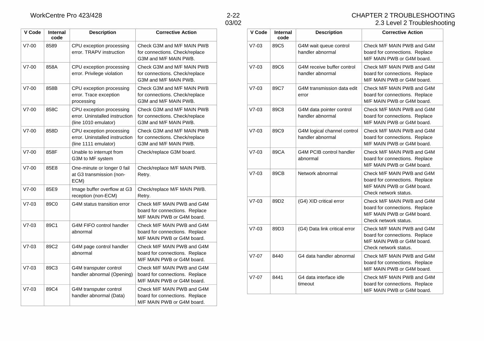
WorkCentre Pro 423/428 2-22 CHAPTER 2 TROUBLESHOOTING03/02 2.3 Level 2 Troubleshooting
V Code Internalcode
Description Corrective Action
V7-00 8589 CPU exception processingerror. TRAPV instruction
Check G3M and M/F MAIN PWBfor connections. Check/replaceG3M and M/F MAIN PWB.
V7-00 858A CPU exception processingerror. Privilege violation
Check G3M and M/F MAIN PWBfor connections. Check/replaceG3M and M/F MAIN PWB.
V7-00 858B CPU exception processingerror. Trace exceptionprocessing
Check G3M and M/F MAIN PWBfor connections. Check/replaceG3M and M/F MAIN PWB.
V7-00 858C CPU exception processingerror. Uninstalled instruction(line 1010 emulator)
Check G3M and M/F MAIN PWBfor connections. Check/replaceG3M and M/F MAIN PWB.
V7-00 858D CPU exception processingerror. Uninstalled instruction(line 1111 emulator)
Check G3M and M/F MAIN PWBfor connections. Check/replaceG3M and M/F MAIN PWB.
V7-00 858F Unable to interrupt fromG3M to MF system
Check/replace G3M board.
V7-00 85E8 One-minute or longer 0 failat G3 transmission (non-ECM)
Check/replace M/F MAIN PWB.Retry.
V7-00 85E9 Image buffer overflow at G3reception (non-ECM)
Check/replace M/F MAIN PWB.Retry.
V7-03 89C0 G4M status transition error Check M/F MAIN PWB and G4Mboard for connections. ReplaceM/F MAIN PWB or G4M board.
V7-03 89C1 G4M FIFO control handlerabnormal
Check M/F MAIN PWB and G4Mboard for connections. ReplaceM/F MAIN PWB or G4M board.
V7-03 89C2 G4M page control handlerabnormal
Check M/F MAIN PWB and G4Mboard for connections. ReplaceM/F MAIN PWB or G4M board.
V7-03 89C3 G4M transputer controlhandler abnormal (Opening)
Check M/F MAIN PWB and G4Mboard for connections. ReplaceM/F MAIN PWB or G4M board.
V7-03 89C4 G4M transputer controlhandler abnormal (Data)
Check M/F MAIN PWB and G4Mboard for connections. ReplaceM/F MAIN PWB or G4M board.
V Code Internalcode
Description Corrective Action
V7-03 89C5 G4M wait queue controlhandler abnormal
Check M/F MAIN PWB and G4Mboard for connections. ReplaceM/F MAIN PWB or G4M board.
V7-03 89C6 G4M receive buffer controlhandler abnormal
Check M/F MAIN PWB and G4Mboard for connections. ReplaceM/F MAIN PWB or G4M board.
V7-03 89C7 G4M transmission data editerror
Check M/F MAIN PWB and G4Mboard for connections. ReplaceM/F MAIN PWB or G4M board.
V7-03 89C8 G4M data pointer controlhandler abnormal
Check M/F MAIN PWB and G4Mboard for connections. ReplaceM/F MAIN PWB or G4M board.
V7-03 89C9 G4M logical channel controlhandler abnormal
Check M/F MAIN PWB and G4Mboard for connections. ReplaceM/F MAIN PWB or G4M board.
V7-03 89CA G4M PCIB control handlerabnormal
Check M/F MAIN PWB and G4Mboard for connections. ReplaceM/F MAIN PWB or G4M board.
V7-03 89CB Network abnormal Check M/F MAIN PWB and G4Mboard for connections. ReplaceM/F MAIN PWB or G4M board.Check network status.
V7-03 89D2 (G4) XID critical error Check M/F MAIN PWB and G4Mboard for connections. ReplaceM/F MAIN PWB or G4M board.Check network status.
V7-03 89D3 (G4) Data link critical error Check M/F MAIN PWB and G4Mboard for connections. ReplaceM/F MAIN PWB or G4M board.Check network status.
V7-07 8440 G4 data handler abnormal Check M/F MAIN PWB and G4Mboard for connections. ReplaceM/F MAIN PWB or G4M board.
V7-07 8441 G4 data interface idletimeout
Check M/F MAIN PWB and G4Mboard for connections. ReplaceM/F MAIN PWB or G4M board.
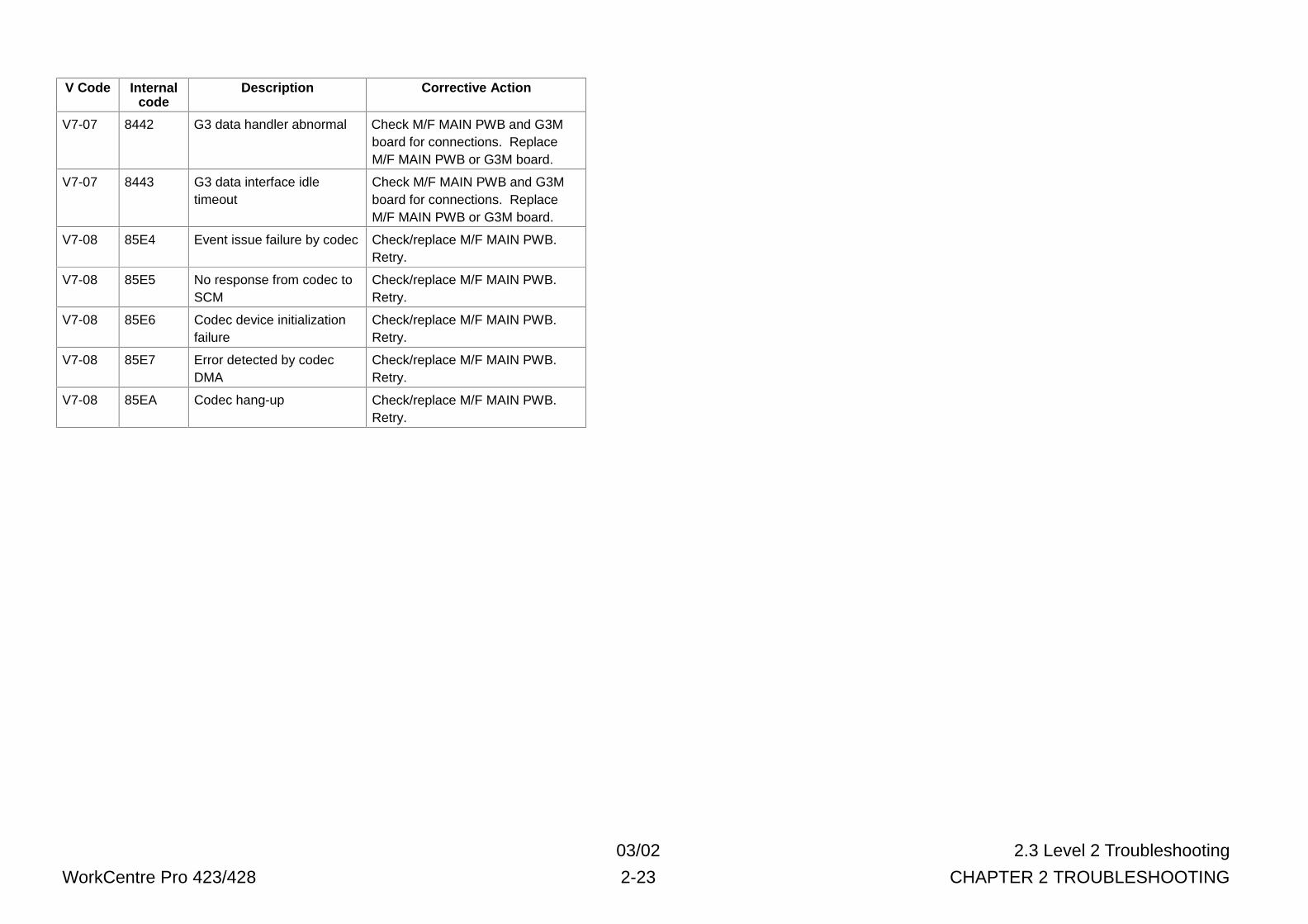
03/02 2.3 Level 2 Troubleshooting
WorkCentre Pro 423/428 2-23 CHAPTER 2 TROUBLESHOOTING
V Code Internalcode
Description Corrective Action
V7-07 8442 G3 data handler abnormal Check M/F MAIN PWB and G3Mboard for connections. ReplaceM/F MAIN PWB or G3M board.
V7-07 8443 G3 data interface idletimeout
Check M/F MAIN PWB and G3Mboard for connections. ReplaceM/F MAIN PWB or G3M board.
V7-08 85E4 Event issue failure by codec Check/replace M/F MAIN PWB.Retry.
V7-08 85E5 No response from codec toSCM
Check/replace M/F MAIN PWB.Retry.
V7-08 85E6 Codec device initializationfailure
Check/replace M/F MAIN PWB.Retry.
V7-08 85E7 Error detected by codecDMA
Check/replace M/F MAIN PWB.Retry.
V7-08 85EA Codec hang-up Check/replace M/F MAIN PWB.Retry.
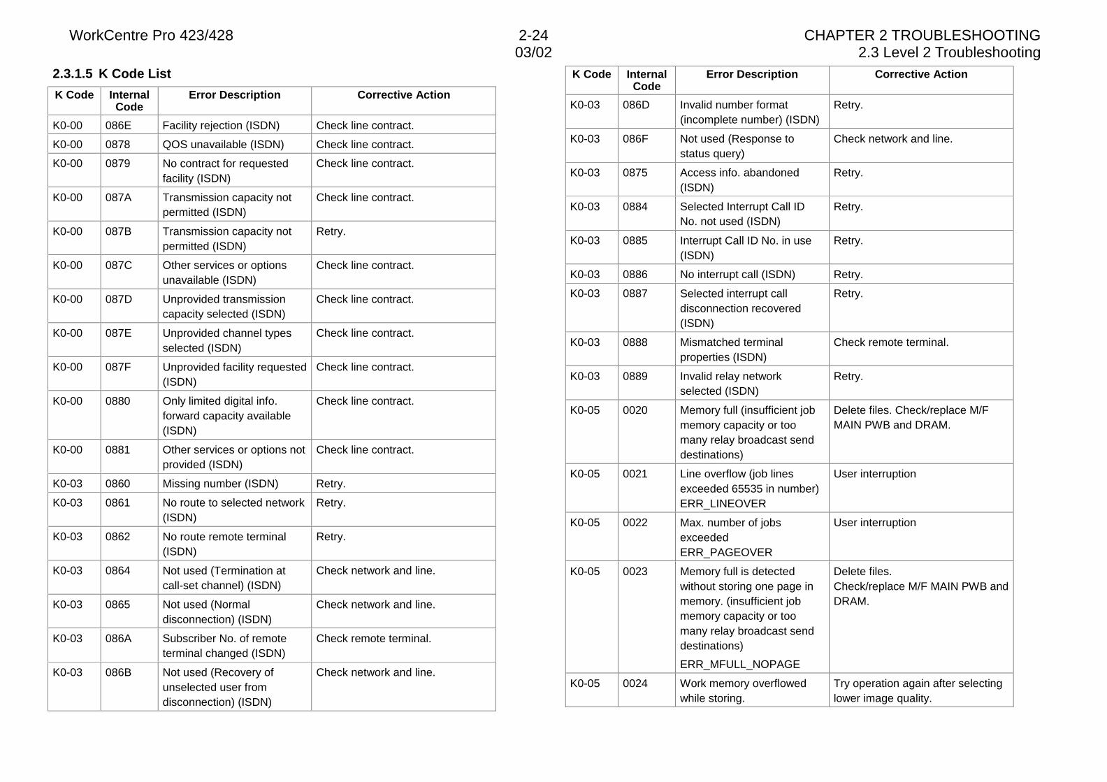
WorkCentre Pro 423/428 2-24 CHAPTER 2 TROUBLESHOOTING03/02 2.3 Level 2 Troubleshooting
2.3.1.5 K Code List
K Code InternalCode
Error Description Corrective Action
K0-00 086E Facility rejection (ISDN) Check line contract.
K0-00 0878 QOS unavailable (ISDN) Check line contract.
K0-00 0879 No contract for requestedfacility (ISDN)
Check line contract.
K0-00 087A Transmission capacity notpermitted (ISDN)
Check line contract.
K0-00 087B Transmission capacity notpermitted (ISDN)
Retry.
K0-00 087C Other services or optionsunavailable (ISDN)
Check line contract.
K0-00 087D Unprovided transmissioncapacity selected (ISDN)
Check line contract.
K0-00 087E Unprovided channel typesselected (ISDN)
Check line contract.
K0-00 087F Unprovided facility requested(ISDN)
Check line contract.
K0-00 0880 Only limited digital info.forward capacity available(ISDN)
Check line contract.
K0-00 0881 Other services or options notprovided (ISDN)
Check line contract.
K0-03 0860 Missing number (ISDN) Retry.
K0-03 0861 No route to selected network(ISDN)
Retry.
K0-03 0862 No route remote terminal(ISDN)
Retry.
K0-03 0864 Not used (Termination atcall-set channel) (ISDN)
Check network and line.
K0-03 0865 Not used (Normaldisconnection) (ISDN)
Check network and line.
K0-03 086A Subscriber No. of remoteterminal changed (ISDN)
Check remote terminal.
K0-03 086B Not used (Recovery ofunselected user fromdisconnection) (ISDN)
Check network and line.
K Code InternalCode
Error Description Corrective Action
K0-03 086D Invalid number format(incomplete number) (ISDN)
Retry.
K0-03 086F Not used (Response tostatus query)
Check network and line.
K0-03 0875 Access info. abandoned(ISDN)
Retry.
K0-03 0884 Selected Interrupt Call IDNo. not used (ISDN)
Retry.
K0-03 0885 Interrupt Call ID No. in use(ISDN)
Retry.
K0-03 0886 No interrupt call (ISDN) Retry.
K0-03 0887 Selected interrupt calldisconnection recovered(ISDN)
Retry.
K0-03 0888 Mismatched terminalproperties (ISDN)
Check remote terminal.
K0-03 0889 Invalid relay networkselected (ISDN)
Retry.
K0-05 0020 Memory full (insufficient jobmemory capacity or toomany relay broadcast senddestinations)
Delete files. Check/replace M/FMAIN PWB and DRAM.
K0-05 0021 Line overflow (job linesexceeded 65535 in number)ERR_LINEOVER
User interruption
K0-05 0022 Max. number of jobsexceededERR_PAGEOVER
User interruption
K0-05 0023 Memory full is detectedwithout storing one page inmemory. (insufficient jobmemory capacity or toomany relay broadcast senddestinations)
ERR_MFULL_NOPAGE
Delete files.Check/replace M/F MAIN PWB andDRAM.
K0-05 0024 Work memory overflowedwhile storing.
Try operation again after selectinglower image quality.
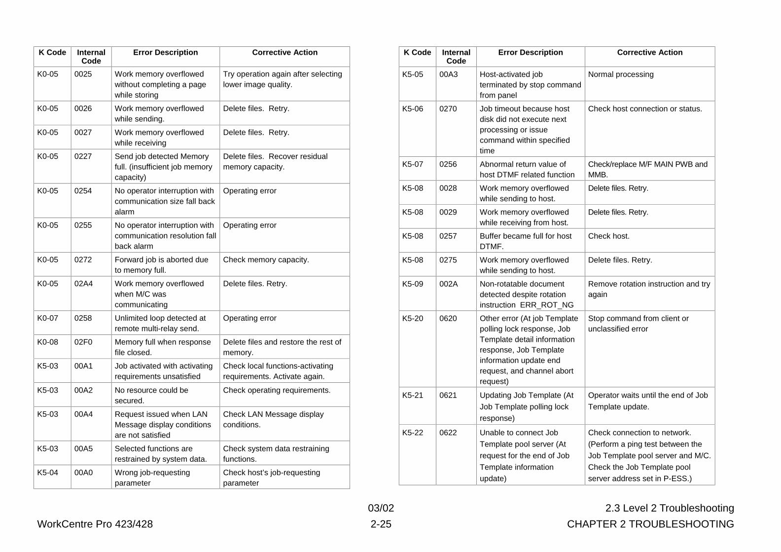
03/02 2.3 Level 2 Troubleshooting
WorkCentre Pro 423/428 2-25 CHAPTER 2 TROUBLESHOOTING
K Code InternalCode
Error Description Corrective Action
K0-05 0025 Work memory overflowedwithout completing a pagewhile storing
Try operation again after selectinglower image quality.
K0-05 0026 Work memory overflowedwhile sending.
Delete files. Retry.
K0-05 0027 Work memory overflowedwhile receiving
Delete files. Retry.
K0-05 0227 Send job detected Memoryfull. (insufficient job memorycapacity)
Delete files. Recover residualmemory capacity.
K0-05 0254 No operator interruption withcommunication size fall backalarm
Operating error
K0-05 0255 No operator interruption withcommunication resolution fallback alarm
Operating error
K0-05 0272 Forward job is aborted dueto memory full.
Check memory capacity.
K0-05 02A4 Work memory overflowedwhen M/C wascommunicating
Delete files. Retry.
K0-07 0258 Unlimited loop detected atremote multi-relay send.
Operating error
K0-08 02F0 Memory full when responsefile closed.
Delete files and restore the rest ofmemory.
K5-03 00A1 Job activated with activatingrequirements unsatisfied
Check local functions-activatingrequirements. Activate again.
K5-03 00A2 No resource could besecured.
Check operating requirements.
K5-03 00A4 Request issued when LANMessage display conditionsare not satisfied
Check LAN Message displayconditions.
K5-03 00A5 Selected functions arerestrained by system data.
Check system data restrainingfunctions.
K5-04 00A0 Wrong job-requestingparameter
Check host’s job-requestingparameter
K Code InternalCode
Error Description Corrective Action
K5-05 00A3 Host-activated jobterminated by stop commandfrom panel
Normal processing
K5-06 0270 Job timeout because hostdisk did not execute nextprocessing or issuecommand within specifiedtime
Check host connection or status.
K5-07 0256 Abnormal return value ofhost DTMF related function
Check/replace M/F MAIN PWB andMMB.
K5-08 0028 Work memory overflowedwhile sending to host.
Delete files. Retry.
K5-08 0029 Work memory overflowedwhile receiving from host.
Delete files. Retry.
K5-08 0257 Buffer became full for hostDTMF.
Check host.
K5-08 0275 Work memory overflowedwhile sending to host.
Delete files. Retry.
K5-09 002A Non-rotatable documentdetected despite rotationinstruction ERR_ROT_NG
Remove rotation instruction and tryagain
K5-20 0620 Other error (At job Templatepolling lock response, JobTemplate detail informationresponse, Job Templateinformation update endrequest, and channel abortrequest)
Stop command from client orunclassified error
K5-21 0621 Updating Job Template (At
Job Template polling lock
response)
Operator waits until the end of Job
Template update.
K5-22 0622 Unable to connect Job
Template pool server (At
request for the end of Job
Template information
update)
Check connection to network.
(Perform a ping test between the
Job Template pool server and M/C.
Check the Job Template pool
server address set in P-ESS.)
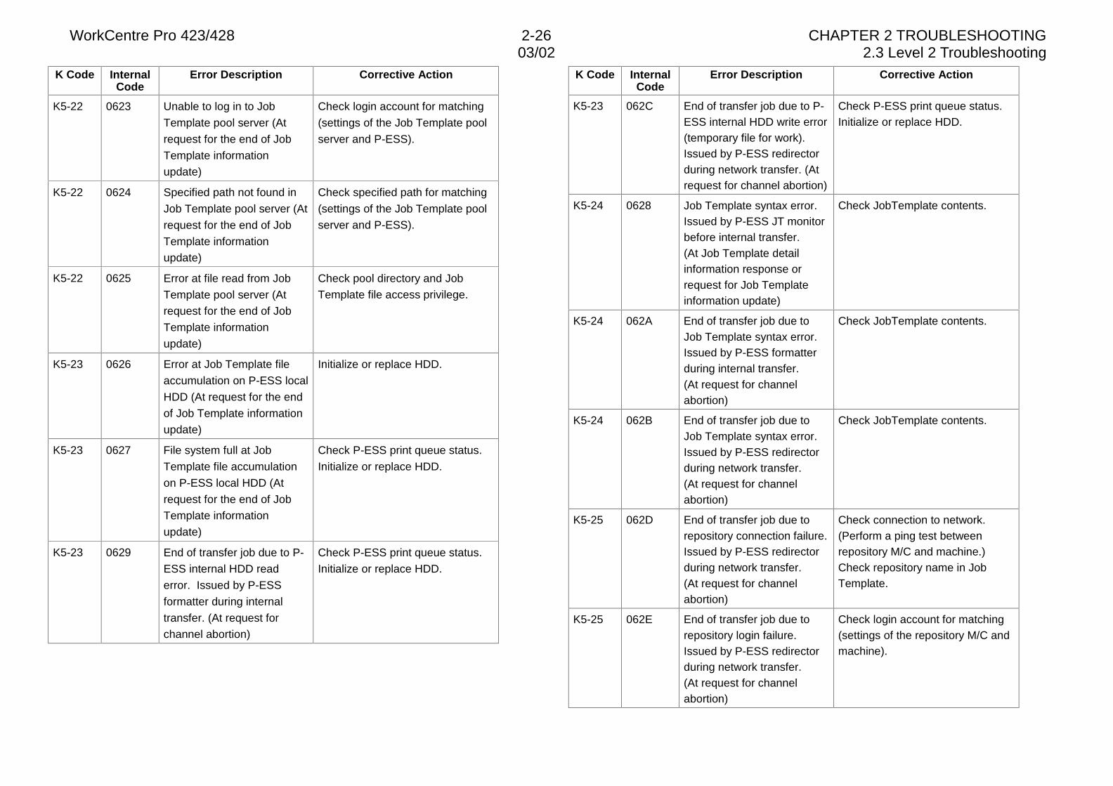
WorkCentre Pro 423/428 2-26 CHAPTER 2 TROUBLESHOOTING03/02 2.3 Level 2 Troubleshooting
K Code InternalCode
Error Description Corrective Action
K5-22 0623 Unable to log in to Job
Template pool server (At
request for the end of Job
Template information
update)
Check login account for matching
(settings of the Job Template pool
server and P-ESS).
K5-22 0624 Specified path not found in
Job Template pool server (At
request for the end of Job
Template information
update)
Check specified path for matching
(settings of the Job Template pool
server and P-ESS).
K5-22 0625 Error at file read from Job
Template pool server (At
request for the end of Job
Template information
update)
Check pool directory and Job
Template file access privilege.
K5-23 0626 Error at Job Template file
accumulation on P-ESS local
HDD (At request for the end
of Job Template information
update)
Initialize or replace HDD.
K5-23 0627 File system full at Job
Template file accumulation
on P-ESS local HDD (At
request for the end of Job
Template information
update)
Check P-ESS print queue status.
Initialize or replace HDD.
K5-23 0629 End of transfer job due to P-
ESS internal HDD read
error. Issued by P-ESS
formatter during internal
transfer. (At request for
channel abortion)
Check P-ESS print queue status.
Initialize or replace HDD.
K Code InternalCode
Error Description Corrective Action
K5-23 062C End of transfer job due to P-ESS internal HDD write error(temporary file for work).Issued by P-ESS redirectorduring network transfer. (Atrequest for channel abortion)
Check P-ESS print queue status.Initialize or replace HDD.
K5-24 0628 Job Template syntax error.Issued by P-ESS JT monitorbefore internal transfer.(At Job Template detailinformation response orrequest for Job Templateinformation update)
Check JobTemplate contents.
K5-24 062A End of transfer job due toJob Template syntax error.Issued by P-ESS formatterduring internal transfer.(At request for channelabortion)
Check JobTemplate contents.
K5-24 062B End of transfer job due toJob Template syntax error.Issued by P-ESS redirectorduring network transfer.(At request for channelabortion)
Check JobTemplate contents.
K5-25 062D End of transfer job due torepository connection failure.Issued by P-ESS redirectorduring network transfer.(At request for channelabortion)
Check connection to network.(Perform a ping test betweenrepository M/C and machine.)Check repository name in JobTemplate.
K5-25 062E End of transfer job due torepository login failure.Issued by P-ESS redirectorduring network transfer.(At request for channelabortion)
Check login account for matching(settings of the repository M/C andmachine).
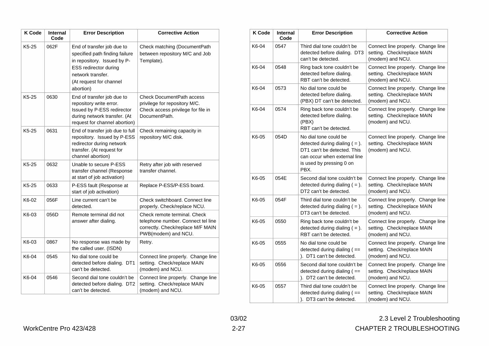
03/02 2.3 Level 2 Troubleshooting
WorkCentre Pro 423/428 2-27 CHAPTER 2 TROUBLESHOOTING
K Code InternalCode
Error Description Corrective Action
K5-25 062F End of transfer job due tospecified path finding failurein repository. Issued by P-ESS redirector duringnetwork transfer.(At request for channelabortion)
Check matching (DocumentPathbetween repository M/C and JobTemplate).
K5-25 0630 End of transfer job due torepository write error.Issued by P-ESS redirectorduring network transfer. (Atrequest for channel abortion)
Check DocumentPath accessprivilege for repository M/C.Check access privilege for file inDocumentPath.
K5-25 0631 End of transfer job due to fullrepository. Issued by P-ESSredirector during networktransfer. (At request forchannel abortion)
Check remaining capacity inrepository M/C disk.
K5-25 0632 Unable to secure P-ESStransfer channel (Responseat start of job activation)
Retry after job with reservedtransfer channel.
K5-25 0633 P-ESS fault (Response atstart of job activation)
Replace P-ESS/P-ESS board.
K6-02 056F Line current can’t bedetected.
Check switchboard. Connect lineproperly. Check/replace NCU.
K6-03 056D Remote terminal did notanswer after dialing.
Check remote terminal. Checktelephone number. Connect tel linecorrectly. Check/replace M/F MAINPWB(modem) and NCU.
K6-03 0867 No response was made bythe called user. (ISDN)
Retry.
K6-04 0545 No dial tone could bedetected before dialing. DT1can’t be detected.
Connect line properly. Change linesetting. Check/replace MAIN(modem) and NCU.
K6-04 0546 Second dial tone couldn’t bedetected before dialing. DT2can’t be detected.
Connect line properly. Change linesetting. Check/replace MAIN(modem) and NCU.
K Code InternalCode
Error Description Corrective Action
K6-04 0547 Third dial tone couldn’t bedetected before dialing. DT3can’t be detected.
Connect line properly. Change linesetting. Check/replace MAIN(modem) and NCU.
K6-04 0548 Ring back tone couldn’t bedetected before dialing.RBT can’t be detected.
Connect line properly. Change linesetting. Check/replace MAIN(modem) and NCU.
K6-04 0573 No dial tone could bedetected before dialing.(PBX) DT can’t be detected.
Connect line properly. Change linesetting. Check/replace MAIN(modem) and NCU.
K6-04 0574 Ring back tone couldn’t bedetected before dialing.(PBX)RBT can’t be detected.
Connect line properly. Change linesetting. Check/replace MAIN(modem) and NCU.
K6-05 054D No dial tone could bedetected during dialing ( = ).DT1 can’t be detected. Thiscan occur when external lineis used by pressing 0 onPBX.
Connect line properly. Change linesetting. Check/replace MAIN(modem) and NCU.
K6-05 054E Second dial tone couldn’t bedetected during dialing ( = ).DT2 can’t be detected.
Connect line properly. Change linesetting. Check/replace MAIN(modem) and NCU.
K6-05 054F Third dial tone couldn’t bedetected during dialing ( = ).DT3 can’t be detected.
Connect line properly. Change linesetting. Check/replace MAIN(modem) and NCU.
K6-05 0550 Ring back tone couldn’t bedetected during dialing ( = ).RBT can’t be detected.
Connect line properly. Change linesetting. Check/replace MAIN(modem) and NCU.
K6-05 0555 No dial tone could bedetected during dialing ( ==). DT1 can’t be detected.
Connect line properly. Change linesetting. Check/replace MAIN(modem) and NCU.
K6-05 0556 Second dial tone couldn’t bedetected during dialing ( ==). DT2 can’t be detected.
Connect line properly. Change linesetting. Check/replace MAIN(modem) and NCU.
K6-05 0557 Third dial tone couldn’t bedetected during dialing ( ==). DT3 can’t be detected.
Connect line properly. Change linesetting. Check/replace MAIN(modem) and NCU.
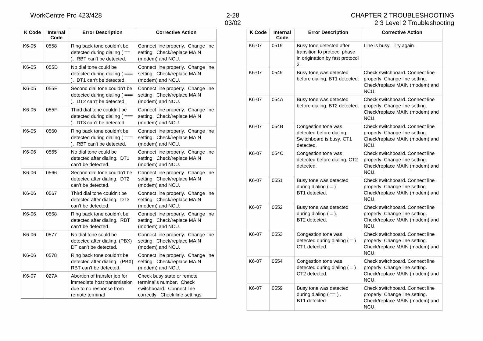
WorkCentre Pro 423/428 2-28 CHAPTER 2 TROUBLESHOOTING03/02 2.3 Level 2 Troubleshooting
K Code InternalCode
Error Description Corrective Action
K6-05 0558 Ring back tone couldn’t bedetected during dialing ( ==). RBT can’t be detected.
Connect line properly. Change linesetting. Check/replace MAIN(modem) and NCU.
K6-05 055D No dial tone could bedetected during dialing ( ===). DT1 can’t be detected.
Connect line properly. Change linesetting. Check/replace MAIN(modem) and NCU.
K6-05 055E Second dial tone couldn’t bedetected during dialing ( ===). DT2 can’t be detected.
Connect line properly. Change linesetting. Check/replace MAIN(modem) and NCU.
K6-05 055F Third dial tone couldn’t bedetected during dialing ( ===). DT3 can’t be detected.
Connect line properly. Change linesetting. Check/replace MAIN(modem) and NCU.
K6-05 0560 Ring back tone couldn’t bedetected during dialing ( ===). RBT can’t be detected.
Connect line properly. Change linesetting. Check/replace MAIN(modem) and NCU.
K6-06 0565 No dial tone could bedetected after dialing. DT1can’t be detected.
Connect line properly. Change linesetting. Check/replace MAIN(modem) and NCU.
K6-06 0566 Second dial tone couldn’t bedetected after dialing. DT2can’t be detected.
Connect line properly. Change linesetting. Check/replace MAIN(modem) and NCU.
K6-06 0567 Third dial tone couldn’t bedetected after dialing. DT3can’t be detected.
Connect line properly. Change linesetting. Check/replace MAIN(modem) and NCU.
K6-06 0568 Ring back tone couldn’t bedetected after dialing. RBTcan’t be detected.
Connect line properly. Change linesetting. Check/replace MAIN(modem) and NCU.
K6-06 0577 No dial tone could bedetected after dialing. (PBX)DT can’t be detected.
Connect line properly. Change linesetting. Check/replace MAIN(modem) and NCU.
K6-06 0578 Ring back tone couldn’t bedetected after dialing. (PBX)RBT can’t be detected.
Connect line properly. Change linesetting. Check/replace MAIN(modem) and NCU.
K6-07 027A Abortion of transfer job forimmediate host transmissiondue to no response fromremote terminal
Check busy state or remoteterminal’s number. Checkswitchboard. Connect linecorrectly. Check line settings.
K Code InternalCode
Error Description Corrective Action
K6-07 0519 Busy tone detected aftertransition to protocol phasein origination by fast protocol2.
Line is busy. Try again.
K6-07 0549 Busy tone was detectedbefore dialing. BT1 detected.
Check switchboard. Connect lineproperly. Change line setting.Check/replace MAIN (modem) andNCU.
K6-07 054A Busy tone was detectedbefore dialing. BT2 detected.
Check switchboard. Connect lineproperly. Change line setting.Check/replace MAIN (modem) andNCU.
K6-07 054B Congestion tone wasdetected before dialing.Switchboard is busy. CT1detected.
Check switchboard. Connect lineproperly. Change line setting.Check/replace MAIN (modem) andNCU.
K6-07 054C Congestion tone wasdetected before dialing. CT2detected.
Check switchboard. Connect lineproperly. Change line setting.Check/replace MAIN (modem) andNCU.
K6-07 0551 Busy tone was detectedduring dialing ( = ).BT1 detected.
Check switchboard. Connect lineproperly. Change line setting.Check/replace MAIN (modem) andNCU.
K6-07 0552 Busy tone was detectedduring dialing ( = ).BT2 detected.
Check switchboard. Connect lineproperly. Change line setting.Check/replace MAIN (modem) andNCU.
K6-07 0553 Congestion tone wasdetected during dialing ( = ) .CT1 detected.
Check switchboard. Connect lineproperly. Change line setting.Check/replace MAIN (modem) andNCU.
K6-07 0554 Congestion tone wasdetected during dialing ( = ) .CT2 detected.
Check switchboard. Connect lineproperly. Change line setting.Check/replace MAIN (modem) andNCU.
K6-07 0559 Busy tone was detectedduring dialing ( == ) .BT1 detected.
Check switchboard. Connect lineproperly. Change line setting.Check/replace MAIN (modem) andNCU.
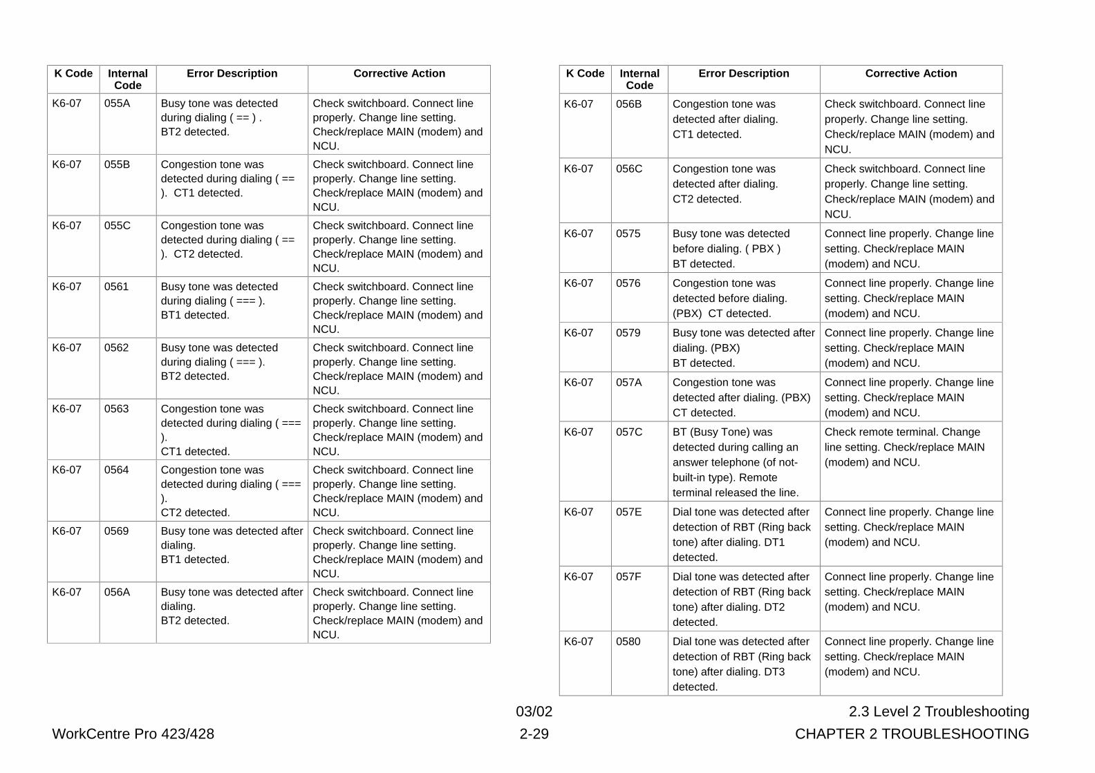
03/02 2.3 Level 2 Troubleshooting
WorkCentre Pro 423/428 2-29 CHAPTER 2 TROUBLESHOOTING
K Code InternalCode
Error Description Corrective Action
K6-07 055A Busy tone was detectedduring dialing ( == ) .BT2 detected.
Check switchboard. Connect lineproperly. Change line setting.Check/replace MAIN (modem) andNCU.
K6-07 055B Congestion tone wasdetected during dialing ( ==). CT1 detected.
Check switchboard. Connect lineproperly. Change line setting.Check/replace MAIN (modem) andNCU.
K6-07 055C Congestion tone wasdetected during dialing ( ==). CT2 detected.
Check switchboard. Connect lineproperly. Change line setting.Check/replace MAIN (modem) andNCU.
K6-07 0561 Busy tone was detectedduring dialing ( === ).BT1 detected.
Check switchboard. Connect lineproperly. Change line setting.Check/replace MAIN (modem) andNCU.
K6-07 0562 Busy tone was detectedduring dialing ( === ).BT2 detected.
Check switchboard. Connect lineproperly. Change line setting.Check/replace MAIN (modem) andNCU.
K6-07 0563 Congestion tone wasdetected during dialing ( ===).CT1 detected.
Check switchboard. Connect lineproperly. Change line setting.Check/replace MAIN (modem) andNCU.
K6-07 0564 Congestion tone wasdetected during dialing ( ===).CT2 detected.
Check switchboard. Connect lineproperly. Change line setting.Check/replace MAIN (modem) andNCU.
K6-07 0569 Busy tone was detected afterdialing.BT1 detected.
Check switchboard. Connect lineproperly. Change line setting.Check/replace MAIN (modem) andNCU.
K6-07 056A Busy tone was detected afterdialing.BT2 detected.
Check switchboard. Connect lineproperly. Change line setting.Check/replace MAIN (modem) andNCU.
K Code InternalCode
Error Description Corrective Action
K6-07 056B Congestion tone wasdetected after dialing.CT1 detected.
Check switchboard. Connect lineproperly. Change line setting.Check/replace MAIN (modem) andNCU.
K6-07 056C Congestion tone wasdetected after dialing.CT2 detected.
Check switchboard. Connect lineproperly. Change line setting.Check/replace MAIN (modem) andNCU.
K6-07 0575 Busy tone was detectedbefore dialing. ( PBX )BT detected.
Connect line properly. Change linesetting. Check/replace MAIN(modem) and NCU.
K6-07 0576 Congestion tone wasdetected before dialing.(PBX) CT detected.
Connect line properly. Change linesetting. Check/replace MAIN(modem) and NCU.
K6-07 0579 Busy tone was detected afterdialing. (PBX)BT detected.
Connect line properly. Change linesetting. Check/replace MAIN(modem) and NCU.
K6-07 057A Congestion tone wasdetected after dialing. (PBX)CT detected.
Connect line properly. Change linesetting. Check/replace MAIN(modem) and NCU.
K6-07 057C BT (Busy Tone) wasdetected during calling ananswer telephone (of not-built-in type). Remoteterminal released the line.
Check remote terminal. Changeline setting. Check/replace MAIN(modem) and NCU.
K6-07 057E Dial tone was detected afterdetection of RBT (Ring backtone) after dialing. DT1detected.
Connect line properly. Change linesetting. Check/replace MAIN(modem) and NCU.
K6-07 057F Dial tone was detected afterdetection of RBT (Ring backtone) after dialing. DT2detected.
Connect line properly. Change linesetting. Check/replace MAIN(modem) and NCU.
K6-07 0580 Dial tone was detected afterdetection of RBT (Ring backtone) after dialing. DT3detected.
Connect line properly. Change linesetting. Check/replace MAIN(modem) and NCU.
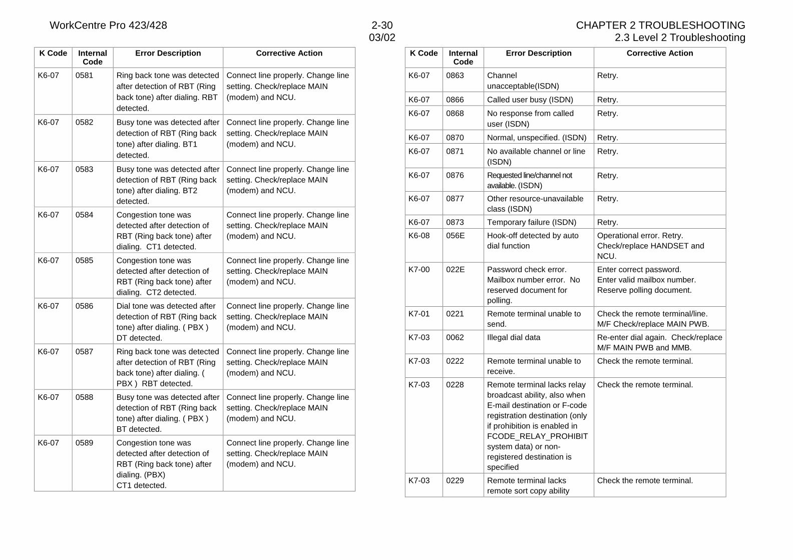
WorkCentre Pro 423/428 2-30 CHAPTER 2 TROUBLESHOOTING03/02 2.3 Level 2 Troubleshooting
K Code InternalCode
Error Description Corrective Action
K6-07 0581 Ring back tone was detectedafter detection of RBT (Ringback tone) after dialing. RBTdetected.
Connect line properly. Change linesetting. Check/replace MAIN(modem) and NCU.
K6-07 0582 Busy tone was detected afterdetection of RBT (Ring backtone) after dialing. BT1detected.
Connect line properly. Change linesetting. Check/replace MAIN(modem) and NCU.
K6-07 0583 Busy tone was detected afterdetection of RBT (Ring backtone) after dialing. BT2detected.
Connect line properly. Change linesetting. Check/replace MAIN(modem) and NCU.
K6-07 0584 Congestion tone wasdetected after detection ofRBT (Ring back tone) afterdialing. CT1 detected.
Connect line properly. Change linesetting. Check/replace MAIN(modem) and NCU.
K6-07 0585 Congestion tone wasdetected after detection ofRBT (Ring back tone) afterdialing. CT2 detected.
Connect line properly. Change linesetting. Check/replace MAIN(modem) and NCU.
K6-07 0586 Dial tone was detected afterdetection of RBT (Ring backtone) after dialing. ( PBX )DT detected.
Connect line properly. Change linesetting. Check/replace MAIN(modem) and NCU.
K6-07 0587 Ring back tone was detectedafter detection of RBT (Ringback tone) after dialing. (PBX ) RBT detected.
Connect line properly. Change linesetting. Check/replace MAIN(modem) and NCU.
K6-07 0588 Busy tone was detected afterdetection of RBT (Ring backtone) after dialing. ( PBX )BT detected.
Connect line properly. Change linesetting. Check/replace MAIN(modem) and NCU.
K6-07 0589 Congestion tone wasdetected after detection ofRBT (Ring back tone) afterdialing. (PBX)CT1 detected.
Connect line properly. Change linesetting. Check/replace MAIN(modem) and NCU.
K Code InternalCode
Error Description Corrective Action
K6-07 0863 Channelunacceptable(ISDN)
Retry.
K6-07 0866 Called user busy (ISDN) Retry.
K6-07 0868 No response from calleduser (ISDN)
Retry.
K6-07 0870 Normal, unspecified. (ISDN) Retry.
K6-07 0871 No available channel or line(ISDN)
Retry.
K6-07 0876 Requested line/channel notavailable. (ISDN)
Retry.
K6-07 0877 Other resource-unavailableclass (ISDN)
Retry.
K6-07 0873 Temporary failure (ISDN) Retry.
K6-08 056E Hook-off detected by autodial function
Operational error. Retry.Check/replace HANDSET andNCU.
K7-00 022E Password check error.Mailbox number error. Noreserved document forpolling.
Enter correct password.Enter valid mailbox number.Reserve polling document.
K7-01 0221 Remote terminal unable tosend.
Check the remote terminal/line.M/F Check/replace MAIN PWB.
K7-03 0062 Illegal dial data Re-enter dial again. Check/replaceM/F MAIN PWB and MMB.
K7-03 0222 Remote terminal unable toreceive.
Check the remote terminal.
K7-03 0228 Remote terminal lacks relaybroadcast ability, also whenE-mail destination or F-coderegistration destination (onlyif prohibition is enabled inFCODE_RELAY_PROHIBITsystem data) or non-registered destination isspecified
Check the remote terminal.
K7-03 0229 Remote terminal lacksremote sort copy ability
Check the remote terminal.
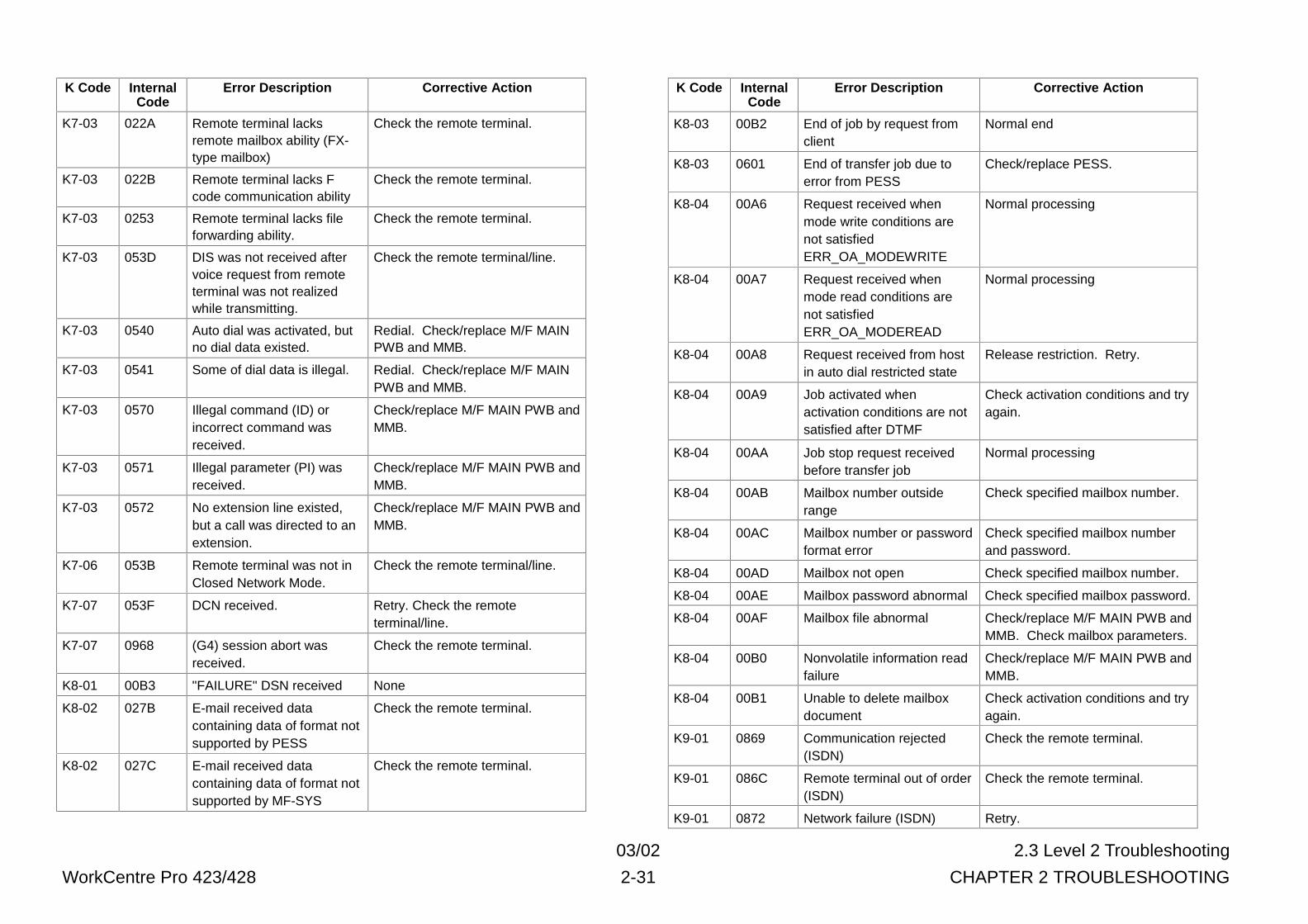
03/02 2.3 Level 2 Troubleshooting
WorkCentre Pro 423/428 2-31 CHAPTER 2 TROUBLESHOOTING
K Code InternalCode
Error Description Corrective Action
K7-03 022A Remote terminal lacksremote mailbox ability (FX-type mailbox)
Check the remote terminal.
K7-03 022B Remote terminal lacks Fcode communication ability
Check the remote terminal.
K7-03 0253 Remote terminal lacks fileforwarding ability.
Check the remote terminal.
K7-03 053D DIS was not received aftervoice request from remoteterminal was not realizedwhile transmitting.
Check the remote terminal/line.
K7-03 0540 Auto dial was activated, butno dial data existed.
Redial. Check/replace M/F MAINPWB and MMB.
K7-03 0541 Some of dial data is illegal. Redial. Check/replace M/F MAINPWB and MMB.
K7-03 0570 Illegal command (ID) orincorrect command wasreceived.
Check/replace M/F MAIN PWB andMMB.
K7-03 0571 Illegal parameter (PI) wasreceived.
Check/replace M/F MAIN PWB andMMB.
K7-03 0572 No extension line existed,but a call was directed to anextension.
Check/replace M/F MAIN PWB andMMB.
K7-06 053B Remote terminal was not inClosed Network Mode.
Check the remote terminal/line.
K7-07 053F DCN received. Retry. Check the remoteterminal/line.
K7-07 0968 (G4) session abort wasreceived.
Check the remote terminal.
K8-01 00B3 "FAILURE" DSN received None
K8-02 027B E-mail received datacontaining data of format notsupported by PESS
Check the remote terminal.
K8-02 027C E-mail received datacontaining data of format notsupported by MF-SYS
Check the remote terminal.
K Code InternalCode
Error Description Corrective Action
K8-03 00B2 End of job by request fromclient
Normal end
K8-03 0601 End of transfer job due toerror from PESS
Check/replace PESS.
K8-04 00A6 Request received whenmode write conditions arenot satisfiedERR_OA_MODEWRITE
Normal processing
K8-04 00A7 Request received whenmode read conditions arenot satisfiedERR_OA_MODEREAD
Normal processing
K8-04 00A8 Request received from hostin auto dial restricted state
Release restriction. Retry.
K8-04 00A9 Job activated whenactivation conditions are notsatisfied after DTMF
Check activation conditions and tryagain.
K8-04 00AA Job stop request receivedbefore transfer job
Normal processing
K8-04 00AB Mailbox number outsiderange
Check specified mailbox number.
K8-04 00AC Mailbox number or passwordformat error
Check specified mailbox numberand password.
K8-04 00AD Mailbox not open Check specified mailbox number.
K8-04 00AE Mailbox password abnormal Check specified mailbox password.
K8-04 00AF Mailbox file abnormal Check/replace M/F MAIN PWB andMMB. Check mailbox parameters.
K8-04 00B0 Nonvolatile information readfailure
Check/replace M/F MAIN PWB andMMB.
K8-04 00B1 Unable to delete mailboxdocument
Check activation conditions and tryagain.
K9-01 0869 Communication rejected(ISDN)
Check the remote terminal.
K9-01 086C Remote terminal out of order(ISDN)
Check the remote terminal.
K9-01 0872 Network failure (ISDN) Retry.
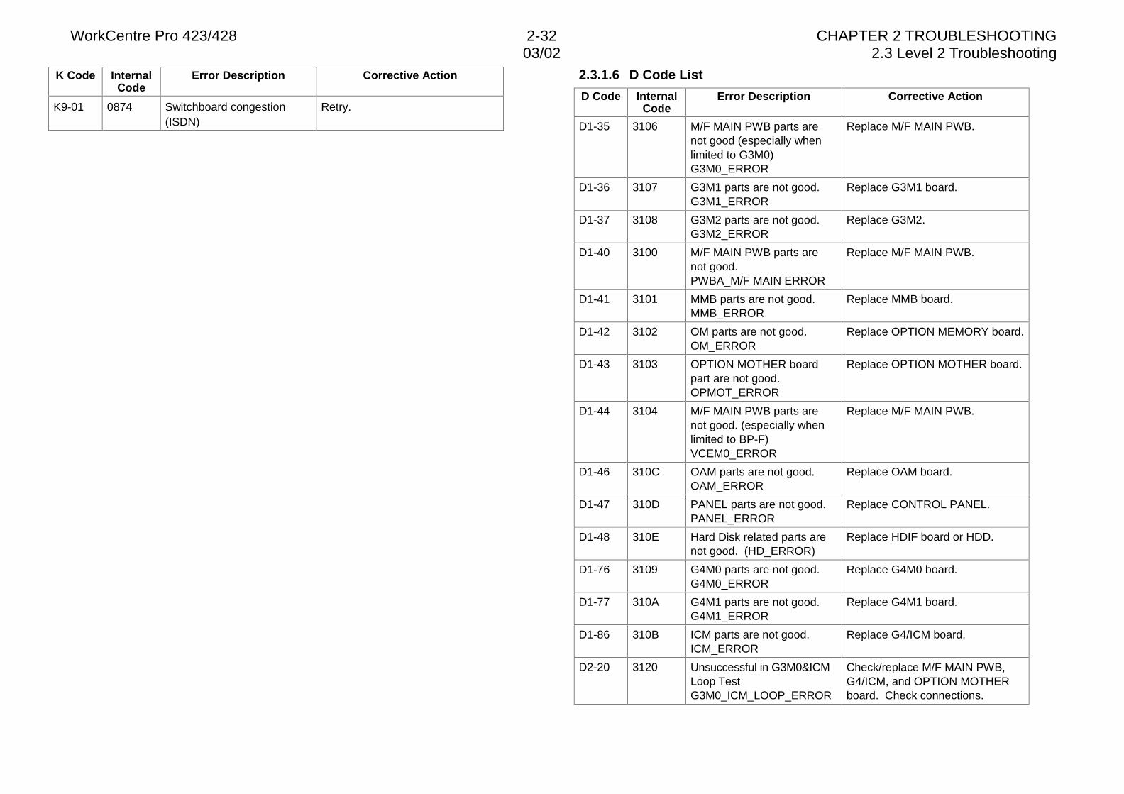
WorkCentre Pro 423/428 2-32 CHAPTER 2 TROUBLESHOOTING03/02 2.3 Level 2 Troubleshooting
K Code InternalCode
Error Description Corrective Action
K9-01 0874 Switchboard congestion(ISDN)
Retry.
2.3.1.6 D Code List
D Code InternalCode
Error Description Corrective Action
D1-35 3106 M/F MAIN PWB parts arenot good (especially whenlimited to G3M0)G3M0_ERROR
Replace M/F MAIN PWB.
D1-36 3107 G3M1 parts are not good.G3M1_ERROR
Replace G3M1 board.
D1-37 3108 G3M2 parts are not good.G3M2_ERROR
Replace G3M2.
D1-40 3100 M/F MAIN PWB parts arenot good.PWBA_M/F MAIN ERROR
Replace M/F MAIN PWB.
D1-41 3101 MMB parts are not good.MMB_ERROR
Replace MMB board.
D1-42 3102 OM parts are not good.OM_ERROR
Replace OPTION MEMORY board.
D1-43 3103 OPTION MOTHER boardpart are not good.OPMOT_ERROR
Replace OPTION MOTHER board.
D1-44 3104 M/F MAIN PWB parts arenot good. (especially whenlimited to BP-F)VCEM0_ERROR
Replace M/F MAIN PWB.
D1-46 310C OAM parts are not good.OAM_ERROR
Replace OAM board.
D1-47 310D PANEL parts are not good.PANEL_ERROR
Replace CONTROL PANEL.
D1-48 310E Hard Disk related parts arenot good. (HD_ERROR)
Replace HDIF board or HDD.
D1-76 3109 G4M0 parts are not good.G4M0_ERROR
Replace G4M0 board.
D1-77 310A G4M1 parts are not good.G4M1_ERROR
Replace G4M1 board.
D1-86 310B ICM parts are not good.ICM_ERROR
Replace G4/ICM board.
D2-20 3120 Unsuccessful in G3M0&ICMLoop TestG3M0_ICM_LOOP_ERROR
Check/replace M/F MAIN PWB,G4/ICM, and OPTION MOTHERboard. Check connections.
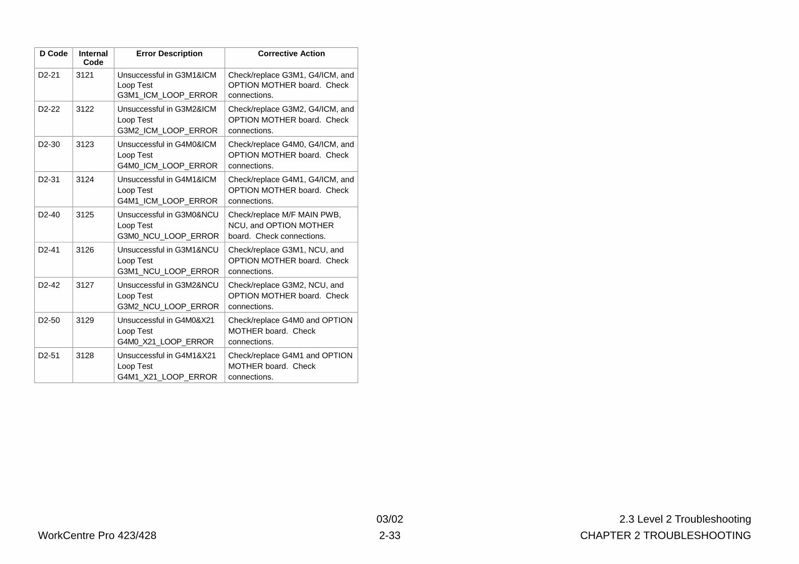
03/02 2.3 Level 2 Troubleshooting
WorkCentre Pro 423/428 2-33 CHAPTER 2 TROUBLESHOOTING
D Code InternalCode
Error Description Corrective Action
D2-21 3121 Unsuccessful in G3M1&ICMLoop TestG3M1_ICM_LOOP_ERROR
Check/replace G3M1, G4/ICM, andOPTION MOTHER board. Checkconnections.
D2-22 3122 Unsuccessful in G3M2&ICMLoop TestG3M2_ICM_LOOP_ERROR
Check/replace G3M2, G4/ICM, andOPTION MOTHER board. Checkconnections.
D2-30 3123 Unsuccessful in G4M0&ICMLoop TestG4M0_ICM_LOOP_ERROR
Check/replace G4M0, G4/ICM, andOPTION MOTHER board. Checkconnections.
D2-31 3124 Unsuccessful in G4M1&ICMLoop TestG4M1_ICM_LOOP_ERROR
Check/replace G4M1, G4/ICM, andOPTION MOTHER board. Checkconnections.
D2-40 3125 Unsuccessful in G3M0&NCULoop TestG3M0_NCU_LOOP_ERROR
Check/replace M/F MAIN PWB,NCU, and OPTION MOTHERboard. Check connections.
D2-41 3126 Unsuccessful in G3M1&NCULoop TestG3M1_NCU_LOOP_ERROR
Check/replace G3M1, NCU, andOPTION MOTHER board. Checkconnections.
D2-42 3127 Unsuccessful in G3M2&NCULoop TestG3M2_NCU_LOOP_ERROR
Check/replace G3M2, NCU, andOPTION MOTHER board. Checkconnections.
D2-50 3129 Unsuccessful in G4M0&X21Loop TestG4M0_X21_LOOP_ERROR
Check/replace G4M0 and OPTIONMOTHER board. Checkconnections.
D2-51 3128 Unsuccessful in G4M1&X21Loop TestG4M1_X21_LOOP_ERROR
Check/replace G4M1 and OPTIONMOTHER board. Checkconnections.
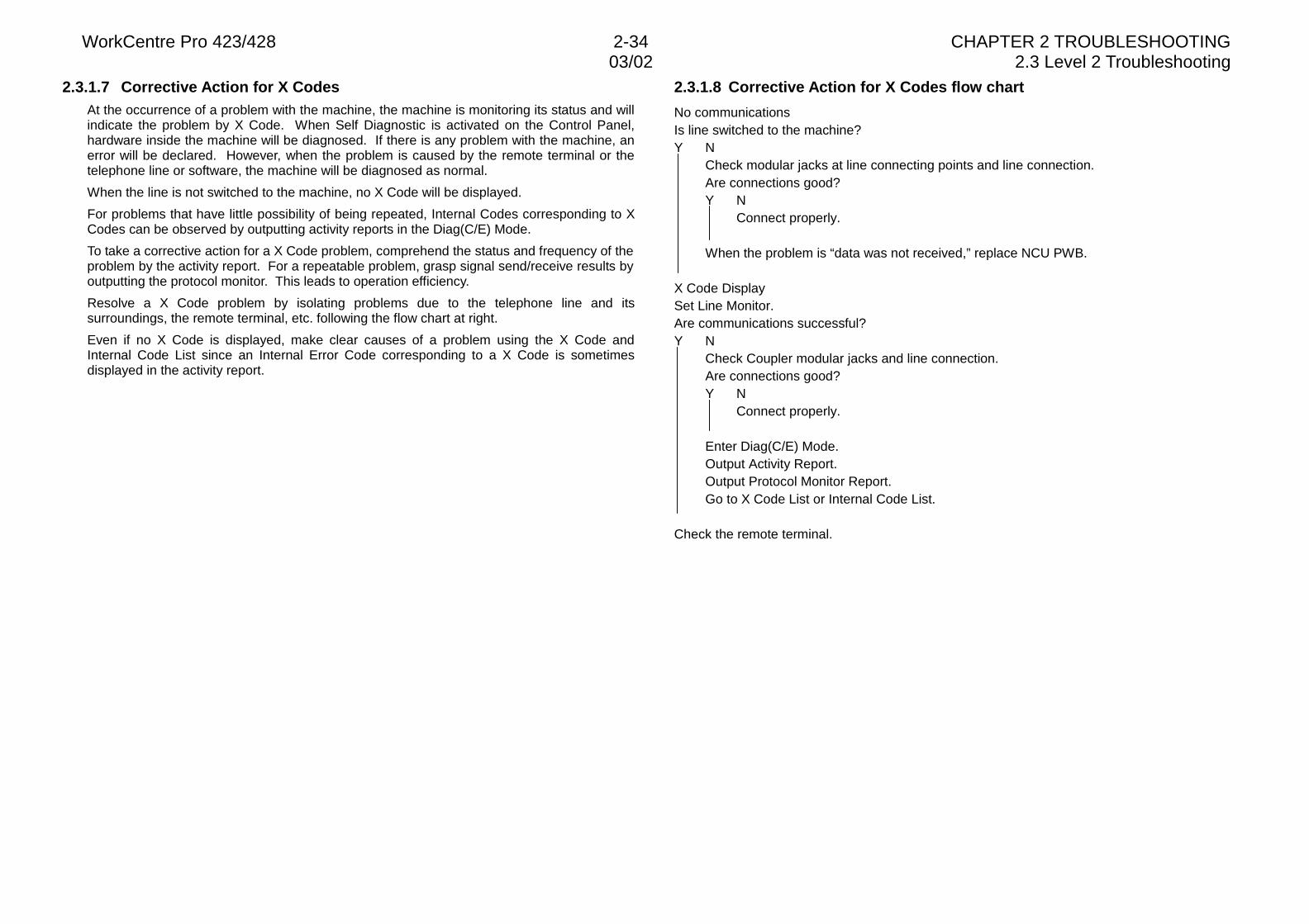
WorkCentre Pro 423/428 2-34 CHAPTER 2 TROUBLESHOOTING03/02 2.3 Level 2 Troubleshooting
2.3.1.7 Corrective Action for X CodesAt the occurrence of a problem with the machine, the machine is monitoring its status and willindicate the problem by X Code. When Self Diagnostic is activated on the Control Panel,hardware inside the machine will be diagnosed. If there is any problem with the machine, anerror will be declared. However, when the problem is caused by the remote terminal or thetelephone line or software, the machine will be diagnosed as normal.
When the line is not switched to the machine, no X Code will be displayed.
For problems that have little possibility of being repeated, Internal Codes corresponding to XCodes can be observed by outputting activity reports in the Diag(C/E) Mode.
To take a corrective action for a X Code problem, comprehend the status and frequency of theproblem by the activity report. For a repeatable problem, grasp signal send/receive results byoutputting the protocol monitor. This leads to operation efficiency.
Resolve a X Code problem by isolating problems due to the telephone line and itssurroundings, the remote terminal, etc. following the flow chart at right.
Even if no X Code is displayed, make clear causes of a problem using the X Code andInternal Code List since an Internal Error Code corresponding to a X Code is sometimesdisplayed in the activity report.
2.3.1.8 Corrective Action for X Codes flow chart
No communicationsIs line switched to the machine?Y N
Check modular jacks at line connecting points and line connection.Are connections good?Y N
Connect properly.
When the problem is “data was not received,” replace NCU PWB.
X Code DisplaySet Line Monitor.Are communications successful?Y N
Check Coupler modular jacks and line connection.Are connections good?Y N
Connect properly.
Enter Diag(C/E) Mode.Output Activity Report.Output Protocol Monitor Report.Go to X Code List or Internal Code List.
Check the remote terminal.
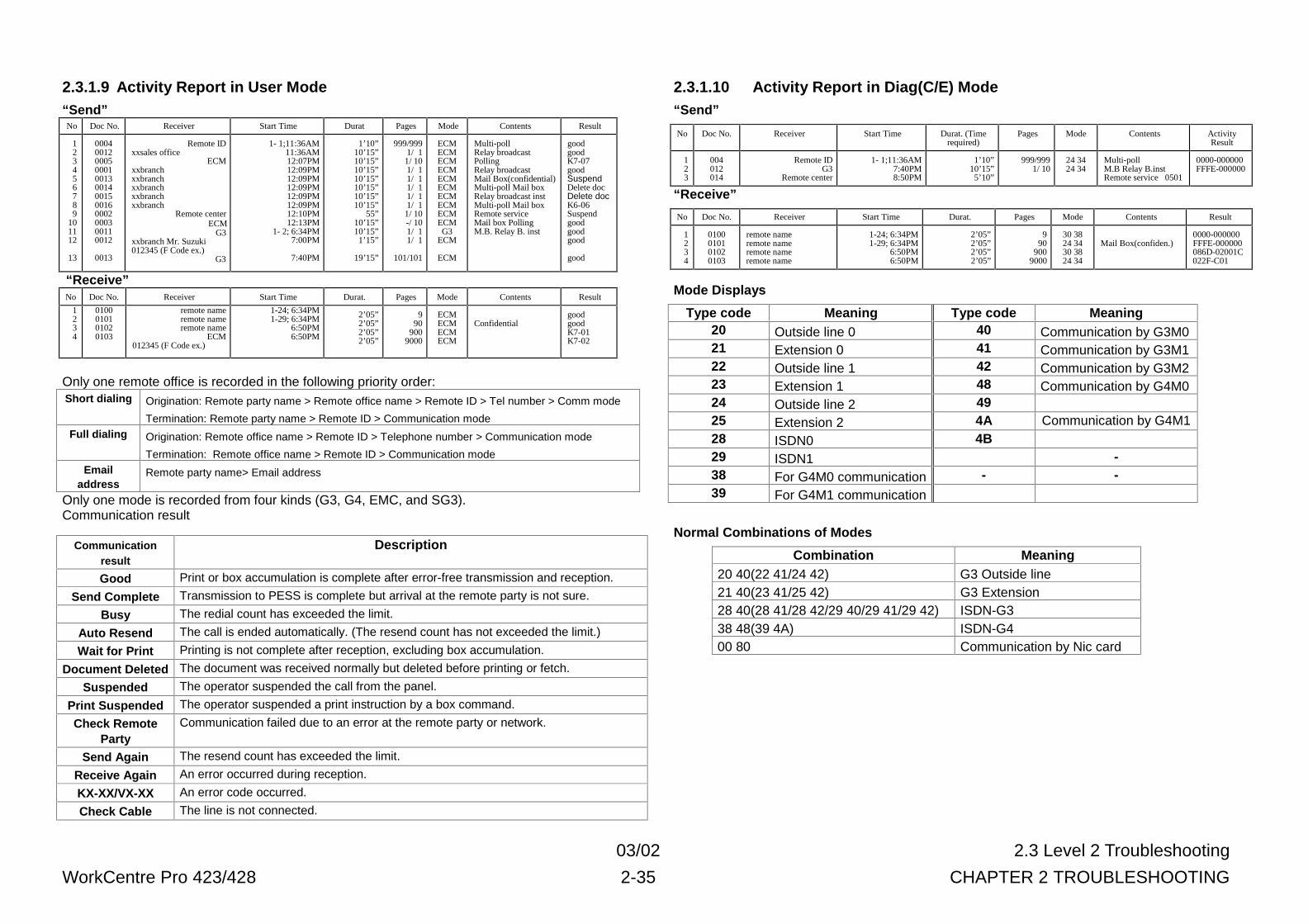
03/02 2.3 Level 2 Troubleshooting
WorkCentre Pro 423/428 2-35 CHAPTER 2 TROUBLESHOOTING
2.3.1.9 Activity Report in User Mode“Send”No Doc No. Receiver Start Time Durat Pages Mode Contents Result
123456789
101112
13
000400120005000100130014001500160002000300110012
0013
Remote IDxxsales office
ECMxxbranchxxbranchxxbranchxxbranchxxbranch
Remote centerECM
G3xxbranch Mr. Suzuki012345 (F Code ex.)
G3
1- 1;11:36AM11:36AM12:07PM12:09PM12:09PM12:09PM12:09PM12:09PM12:10PM12:13PM
1- 2; 6:34PM 7:00PM
7:40PM
1’10”10’15”10’15”10’15”10’15”10’15”10’15”10’15”
55”10’15”10’15”1’15”
19’15”
999/9991/ 11/ 101/ 11/ 11/ 11/ 11/ 11/ 10-/ 101/ 11/ 1
101/101
ECMECMECMECMECMECMECMECMECMECMG3
ECM
ECM
Multi-poll Relay broadcastPollingRelay broadcastMail Box(confidential)Multi-poll Mail boxRelay broadcast instMulti-poll Mail boxRemote serviceMail box PollingM.B. Relay B. inst
goodgoodK7-07goodSuspendDelete docDelete docK6-06Suspendgoodgoodgood
good
“Receive”No Doc No. Receiver Start Time Durat. Pages Mode Contents Result
1234
0100010101020103
remote nameremote nameremote name
ECM012345 (F Code ex.)
1-24; 6:34PM1-29; 6:34PM
6:50PM 6:50PM
2’05”2’05”2’05”2’05”
990
9009000
ECMECMECMECM
ConfidentialgoodgoodK7-01K7-02
Only one remote office is recorded in the following priority order:Short dialing Origination: Remote party name > Remote office name > Remote ID > Tel number > Comm mode
Termination: Remote party name > Remote ID > Communication modeFull dialing Origination: Remote office name > Remote ID > Telephone number > Communication mode
Termination: Remote office name > Remote ID > Communication modeEmail
addressRemote party name> Email address
Only one mode is recorded from four kinds (G3, G4, EMC, and SG3).Communication result
Communicationresult
Description
Good Print or box accumulation is complete after error-free transmission and reception.
Send Complete Transmission to PESS is complete but arrival at the remote party is not sure.
Busy The redial count has exceeded the limit.
Auto Resend The call is ended automatically. (The resend count has not exceeded the limit.)
Wait for Print Printing is not complete after reception, excluding box accumulation.
Document Deleted The document was received normally but deleted before printing or fetch.
Suspended The operator suspended the call from the panel.
Print Suspended The operator suspended a print instruction by a box command.
Check RemoteParty
Communication failed due to an error at the remote party or network.
Send Again The resend count has exceeded the limit.
Receive Again An error occurred during reception.
KX-XX/VX-XX An error code occurred.
Check Cable The line is not connected.
2.3.1.10 Activity Report in Diag(C/E) Mode“Send”
No Doc No. Receiver Start Time Durat. (Timerequired)
Pages Mode Contents ActivityResult
123
004012014
Remote IDG3
Remote center
1- 1;11:36AM7:40PM8:50PM
1’10”10’15”5’10”
999/9991/ 10
24 3424 34
Multi-pollM.B Relay B.instRemote service 0501
0000-000000FFFE-000000
“Receive”
No Doc No. Receiver Start Time Durat. Pages Mode Contents Result
1234
0100010101020103
remote nameremote nameremote nameremote name
1-24; 6:34PM1-29; 6:34PM
6:50PM 6:50PM
2’05”2’05”2’05”2’05”
990
9009000
30 3824 3430 3824 34
Mail Box(confiden.)0000-000000FFFE-000000086D-02001C022F-C01
Mode Displays
Type code Meaning Type code Meaning20 Outside line 0 40 Communication by G3M021 Extension 0 41 Communication by G3M122 Outside line 1 42 Communication by G3M223 Extension 1 48 Communication by G4M024 Outside line 2 4925 Extension 2 4A Communication by G4M128 ISDN0 4B29 ISDN1 -38 For G4M0 communication - -39 For G4M1 communication
Normal Combinations of Modes
Combination Meaning20 40(22 41/24 42) G3 Outside line21 40(23 41/25 42) G3 Extension28 40(28 41/28 42/29 40/29 41/29 42) ISDN-G338 48(39 4A) ISDN-G400 80 Communication by Nic card
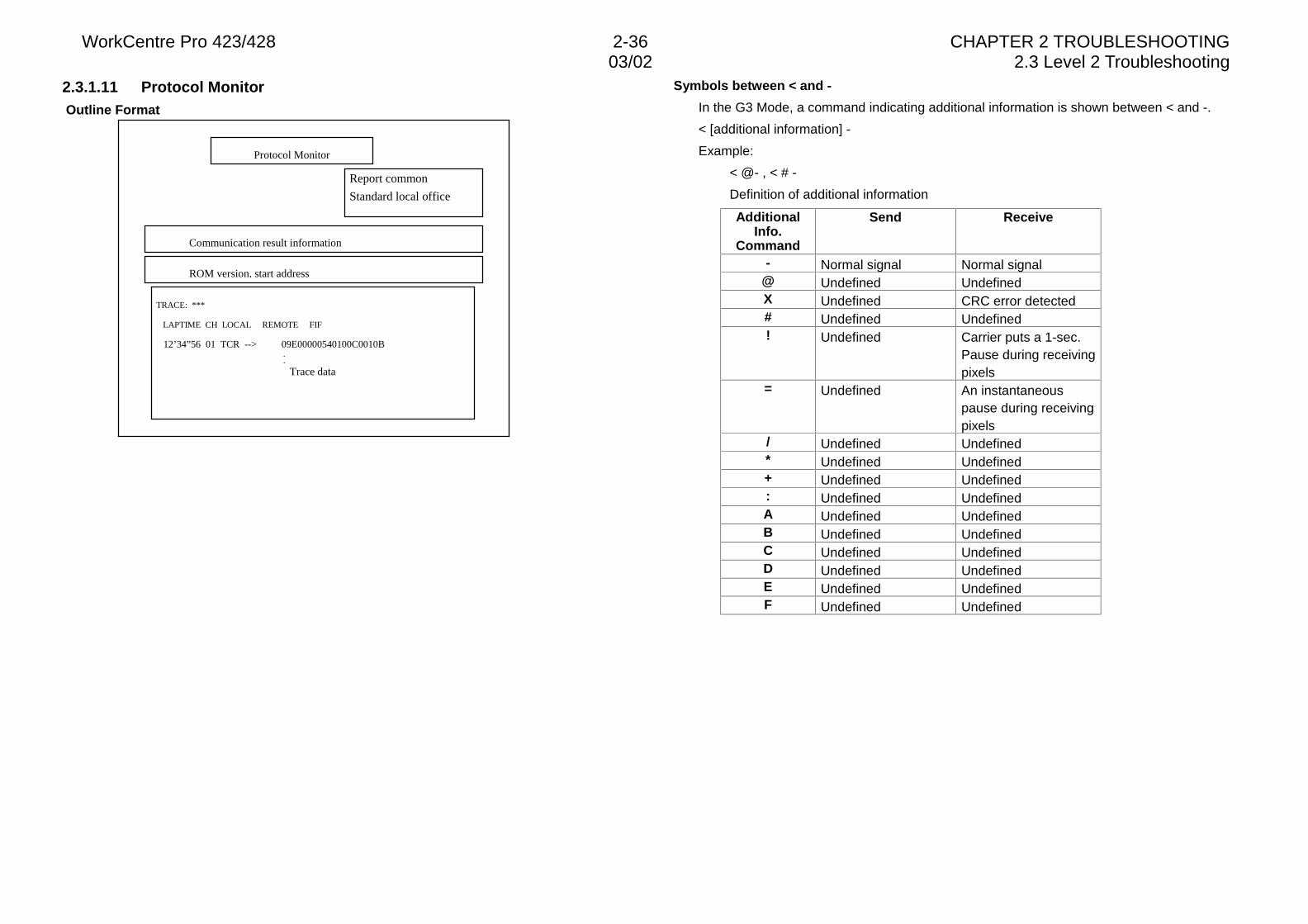
WorkCentre Pro 423/428 2-36 CHAPTER 2 TROUBLESHOOTING03/02 2.3 Level 2 Troubleshooting
2.3.1.11 Protocol Monitor Outline Format
Symbols between < and -
In the G3 Mode, a command indicating additional information is shown between < and -.
< [additional information] -
Example:
< @- , < # -
Definition of additional information
AdditionalInfo.
Command
Send Receive
- Normal signal Normal signal@ Undefined UndefinedX Undefined CRC error detected# Undefined Undefined! Undefined Carrier puts a 1-sec.
Pause during receivingpixels
= Undefined An instantaneouspause during receivingpixels
/ Undefined Undefined* Undefined Undefined+ Undefined Undefined: Undefined UndefinedA Undefined UndefinedB Undefined UndefinedC Undefined UndefinedD Undefined UndefinedE Undefined UndefinedF Undefined Undefined
TRACE: ***
LAPTIME CH LOCAL REMOTE FIF
12’34”56 01 TCR --> 09E00000540100C0010B..
Trace data
Protocol Monitor
Report common
Standard local office
Communication result information
ROM version, start address
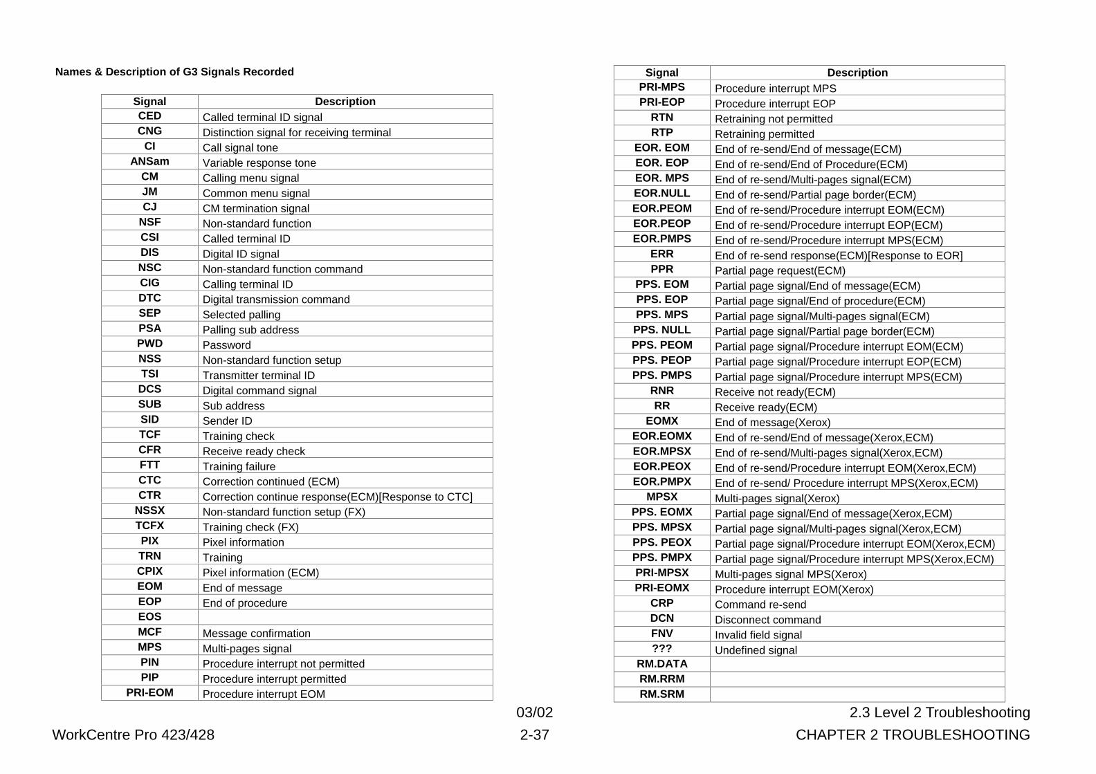
03/02 2.3 Level 2 Troubleshooting
WorkCentre Pro 423/428 2-37 CHAPTER 2 TROUBLESHOOTING
Names & Description of G3 Signals Recorded
Signal DescriptionCED Called terminal ID signalCNG Distinction signal for receiving terminal
CI Call signal toneANSam Variable response tone
CM Calling menu signalJM Common menu signalCJ CM termination signal
NSF Non-standard functionCSI Called terminal IDDIS Digital ID signalNSC Non-standard function commandCIG Calling terminal IDDTC Digital transmission commandSEP Selected pallingPSA Palling sub addressPWD PasswordNSS Non-standard function setupTSI Transmitter terminal ID
DCS Digital command signalSUB Sub addressSID Sender IDTCF Training checkCFR Receive ready checkFTT Training failureCTC Correction continued (ECM)CTR Correction continue response(ECM)[Response to CTC]
NSSX Non-standard function setup (FX)TCFX Training check (FX)PIX Pixel informationTRN TrainingCPIX Pixel information (ECM)EOM End of messageEOP End of procedureEOSMCF Message confirmationMPS Multi-pages signalPIN Procedure interrupt not permittedPIP Procedure interrupt permitted
PRI-EOM Procedure interrupt EOM
Signal DescriptionPRI-MPS Procedure interrupt MPSPRI-EOP Procedure interrupt EOP
RTN Retraining not permittedRTP Retraining permitted
EOR. EOM End of re-send/End of message(ECM)EOR. EOP End of re-send/End of Procedure(ECM)EOR. MPS End of re-send/Multi-pages signal(ECM)EOR.NULL End of re-send/Partial page border(ECM)EOR.PEOM End of re-send/Procedure interrupt EOM(ECM)EOR.PEOP End of re-send/Procedure interrupt EOP(ECM)EOR.PMPS End of re-send/Procedure interrupt MPS(ECM)
ERR End of re-send response(ECM)[Response to EOR]PPR Partial page request(ECM)
PPS. EOM Partial page signal/End of message(ECM)PPS. EOP Partial page signal/End of procedure(ECM)PPS. MPS Partial page signal/Multi-pages signal(ECM)PPS. NULL Partial page signal/Partial page border(ECM)PPS. PEOM Partial page signal/Procedure interrupt EOM(ECM)PPS. PEOP Partial page signal/Procedure interrupt EOP(ECM)PPS. PMPS Partial page signal/Procedure interrupt MPS(ECM)
RNR Receive not ready(ECM)RR Receive ready(ECM)
EOMX End of message(Xerox)EOR.EOMX End of re-send/End of message(Xerox,ECM)EOR.MPSX End of re-send/Multi-pages signal(Xerox,ECM)EOR.PEOX End of re-send/Procedure interrupt EOM(Xerox,ECM)EOR.PMPX End of re-send/ Procedure interrupt MPS(Xerox,ECM)
MPSX Multi-pages signal(Xerox)PPS. EOMX Partial page signal/End of message(Xerox,ECM)PPS. MPSX Partial page signal/Multi-pages signal(Xerox,ECM)PPS. PEOX Partial page signal/Procedure interrupt EOM(Xerox,ECM)PPS. PMPX Partial page signal/Procedure interrupt MPS(Xerox,ECM)PRI-MPSX Multi-pages signal MPS(Xerox)PRI-EOMX Procedure interrupt EOM(Xerox)
CRP Command re-sendDCN Disconnect commandFNV Invalid field signal??? Undefined signal
RM.DATARM.RRMRM.SRM
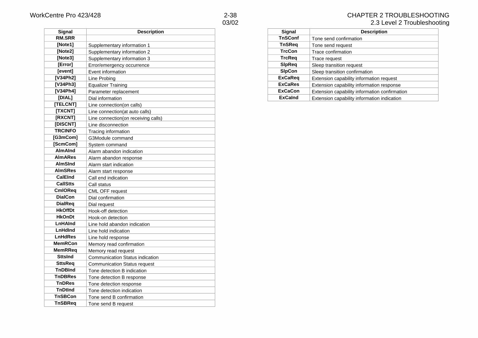
WorkCentre Pro 423/428 2-38 CHAPTER 2 TROUBLESHOOTING03/02 2.3 Level 2 Troubleshooting
Signal DescriptionRM.SRR[Note1] Supplementary information 1[Note2] Supplementary information 2[Note3] Supplementary information 3[Error] Error/emergency occurrence[event] Event information
[V34Ph2] Line Probing[V34Ph3] Equalizer Training[V34Ph4] Parameter replacement
[DIAL] Dial information[TELCNT] Line connection(on calls)[TXCNT] Line connection(at auto calls)[RXCNT] Line connection(on receiving calls)[DISCNT] Line disconnectionTRCINFO Tracing information
[G3mCom] G3Module command[ScmCom] System commandAlmAInd Alarm abandon indicationAlmARes Alarm abandon responseAlmSInd Alarm start indicationAlmSRes Alarm start responseCalEInd Call end indicationCallStts Call status
CmlOReq CML OFF requestDialCon Dial confirmationDialReq Dial requestHkOffDt Hook-off detectionHkOnDt Hook-on detectionLnHAInd Line hold abandon indicationLnHdInd Line hold indicationLnHdRes Line hold responseMemRCon Memory read confirmationMemRReq Memory read request
SttsInd Communication Status indicationSttsReq Communication Status requestTnDBInd Tone detection B indicationTnDBRes Tone detection B responseTnDRes Tone detection responseTnDtInd Tone detection indication
TnSBCon Tone send B confirmationTnSBReq Tone send B request
Signal DescriptionTnSConf Tone send confirmationTnSReq Tone send requestTrcCon Trace confirmationTrcReq Trace requestSlpReq Sleep transition requestSlpCon Sleep transition confirmation
ExCaReq Extension capability information requestExCaRes Extension capability information responseExCaCon Extension capability information confirmationExCaInd Extension capability information indication
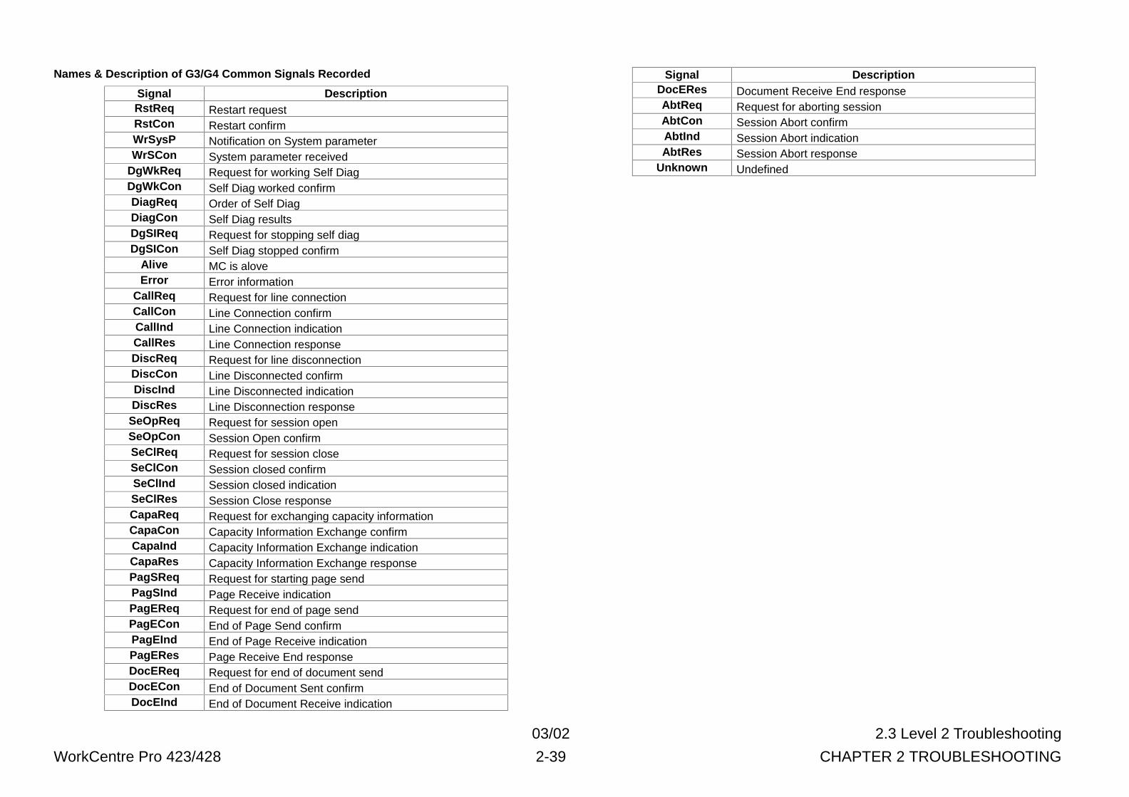
03/02 2.3 Level 2 Troubleshooting
WorkCentre Pro 423/428 2-39 CHAPTER 2 TROUBLESHOOTING
Names & Description of G3/G4 Common Signals Recorded
Signal DescriptionRstReq Restart requestRstCon Restart confirmWrSysP Notification on System parameterWrSCon System parameter received
DgWkReq Request for working Self DiagDgWkCon Self Diag worked confirmDiagReq Order of Self DiagDiagCon Self Diag resultsDgSIReq Request for stopping self diagDgSICon Self Diag stopped confirm
Alive MC is aloveError Error information
CallReq Request for line connectionCallCon Line Connection confirmCallInd Line Connection indicationCallRes Line Connection responseDiscReq Request for line disconnectionDiscCon Line Disconnected confirmDiscInd Line Disconnected indicationDiscRes Line Disconnection response
SeOpReq Request for session openSeOpCon Session Open confirmSeClReq Request for session closeSeClCon Session closed confirmSeClInd Session closed indicationSeClRes Session Close responseCapaReq Request for exchanging capacity informationCapaCon Capacity Information Exchange confirmCapaInd Capacity Information Exchange indicationCapaRes Capacity Information Exchange responsePagSReq Request for starting page sendPagSInd Page Receive indicationPagEReq Request for end of page sendPagECon End of Page Send confirmPagEInd End of Page Receive indicationPagERes Page Receive End responseDocEReq Request for end of document sendDocECon End of Document Sent confirmDocEInd End of Document Receive indication
Signal DescriptionDocERes Document Receive End responseAbtReq Request for aborting sessionAbtCon Session Abort confirmAbtInd Session Abort indicationAbtRes Session Abort response
Unknown Undefined
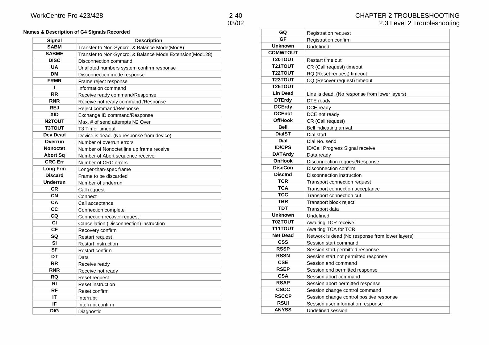
WorkCentre Pro 423/428 2-40 CHAPTER 2 TROUBLESHOOTING03/02 2.3 Level 2 Troubleshooting
Names & Description of G4 Signals Recorded
Signal DescriptionSABM Transfer to Non-Syncro. & Balance Mode(Mod8)
SABME Transfer to Non-Syncro. & Balance Mode Extension(Mod128)DISC Disconnection commandUA Unalloted numbers system confirm responseDM Disconnection mode response
FRMR Frame reject responseI Information command
RR Receive ready command/ResponseRNR Receive not ready command /ResponseREJ Reject command/ResponseXID Exchange ID command/Response
N2TOUT Max. # of send attempts N2 OverT3TOUT T3 Timer timeout
Dev Dead Device is dead. (No response from device)Overrun Number of overrun errorsNonoctet Number of Nonoctet line up frame receiveAbort Sq Number of Abort sequence receiveCRC Err Number of CRC errors
Long Frm Longer-than-spec frameDiscard Frame to be discarded
Underrun Number of underrunCR Call requestCN ConnectCA Call acceptanceCC Connection completeCQ Connection recover requestCI Cancellation (Disconnection) instructionCF Recovery confirmSQ Restart requestSI Restart instructionSF Restart confirmDT DataRR Receive ready
RNR Receive not readyRQ Reset requestRI Reset instructionRF Reset confirmIT InterruptIF Interrupt confirm
DIG Diagnostic
GQ Registration requestGF Registration confirm
Unknown UndefinedCOMWTOUT
T20TOUT Restart time outT21TOUT CR (Call request) timeoutT22TOUT RQ (Reset request) timeoutT23TOUT CQ (Recover request) timeoutT25TOUTLin Dead Line is dead. (No response from lower layers)DTErdy DTE readyDCErdy DCE readyDCEnot DCE not readyOffHook CR (Call request)
Bell Bell indicating arrivalDialST Dial start
Dial Dial No. sendID/CPS ID/Call Progress Signal receive
DATArdy Data readyOnHook Disconnection request/ResponseDiscCon Disconnection confirmDiscInd Disconnection instruction
TCR Transport connection requestTCA Transport connection acceptanceTCC Transport connection cutTBR Transport block rejectTDT Transport data
Unknown UndefinedT02TOUT Awaiting TCR receiveT11TOUT Awaiting TCA for TCRNet Dead Network is dead (No response from lower layers)
CSS Session start commandRSSP Session start permitted responseRSSN Session start not permitted responseCSE Session end command
RSEP Session end permitted responseCSA Session abort command
RSAP Session abort permitted responseCSCC Session change control command
RSCCP Session change control positive responseRSUI Session user information response
ANYSS Undefined session
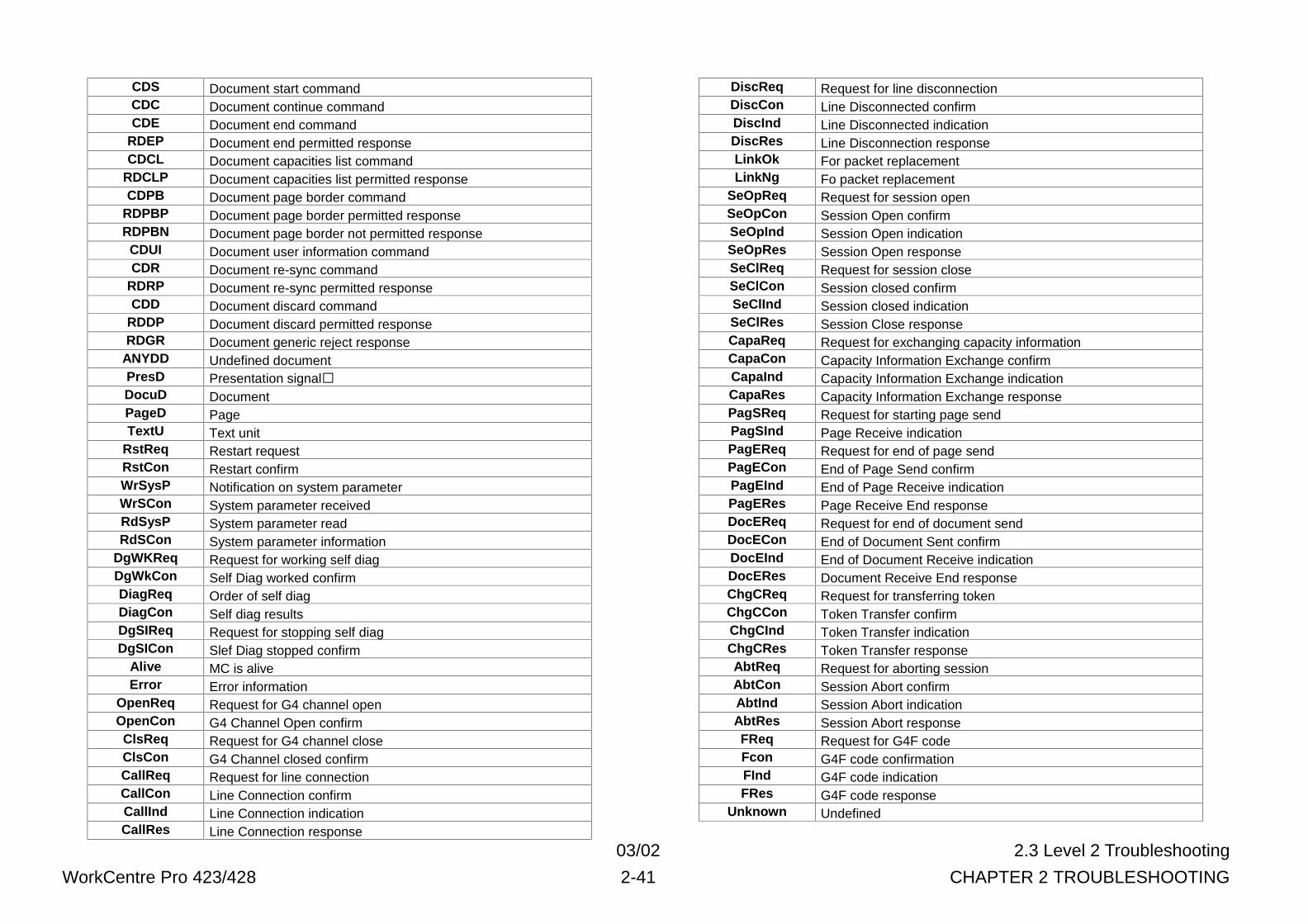
03/02 2.3 Level 2 Troubleshooting
WorkCentre Pro 423/428 2-41 CHAPTER 2 TROUBLESHOOTING
CDS Document start commandCDC Document continue commandCDE Document end command
RDEP Document end permitted responseCDCL Document capacities list command
RDCLP Document capacities list permitted responseCDPB Document page border command
RDPBP Document page border permitted responseRDPBN Document page border not permitted responseCDUI Document user information commandCDR Document re-sync command
RDRP Document re-sync permitted responseCDD Document discard command
RDDP Document discard permitted responseRDGR Document generic reject response
ANYDD Undefined documentPresD Presentation signal�DocuD DocumentPageD PageTextU Text unit
RstReq Restart requestRstCon Restart confirmWrSysP Notification on system parameterWrSCon System parameter receivedRdSysP System parameter readRdSCon System parameter information
DgWKReq Request for working self diagDgWkCon Self Diag worked confirmDiagReq Order of self diagDiagCon Self diag resultsDgSIReq Request for stopping self diagDgSICon Slef Diag stopped confirm
Alive MC is aliveError Error information
OpenReq Request for G4 channel openOpenCon G4 Channel Open confirmClsReq Request for G4 channel closeClsCon G4 Channel closed confirmCallReq Request for line connectionCallCon Line Connection confirmCallInd Line Connection indicationCallRes Line Connection response
DiscReq Request for line disconnectionDiscCon Line Disconnected confirmDiscInd Line Disconnected indicationDiscRes Line Disconnection responseLinkOk For packet replacementLinkNg Fo packet replacement
SeOpReq Request for session openSeOpCon Session Open confirmSeOpInd Session Open indicationSeOpRes Session Open responseSeClReq Request for session closeSeClCon Session closed confirmSeClInd Session closed indicationSeClRes Session Close responseCapaReq Request for exchanging capacity informationCapaCon Capacity Information Exchange confirmCapaInd Capacity Information Exchange indicationCapaRes Capacity Information Exchange responsePagSReq Request for starting page sendPagSInd Page Receive indicationPagEReq Request for end of page sendPagECon End of Page Send confirmPagEInd End of Page Receive indicationPagERes Page Receive End responseDocEReq Request for end of document sendDocECon End of Document Sent confirmDocEInd End of Document Receive indicationDocERes Document Receive End responseChgCReq Request for transferring tokenChgCCon Token Transfer confirmChgCInd Token Transfer indicationChgCRes Token Transfer responseAbtReq Request for aborting sessionAbtCon Session Abort confirmAbtInd Session Abort indicationAbtRes Session Abort responseFReq Request for G4F codeFcon G4F code confirmationFInd G4F code indicationFRes G4F code response
Unknown Undefined
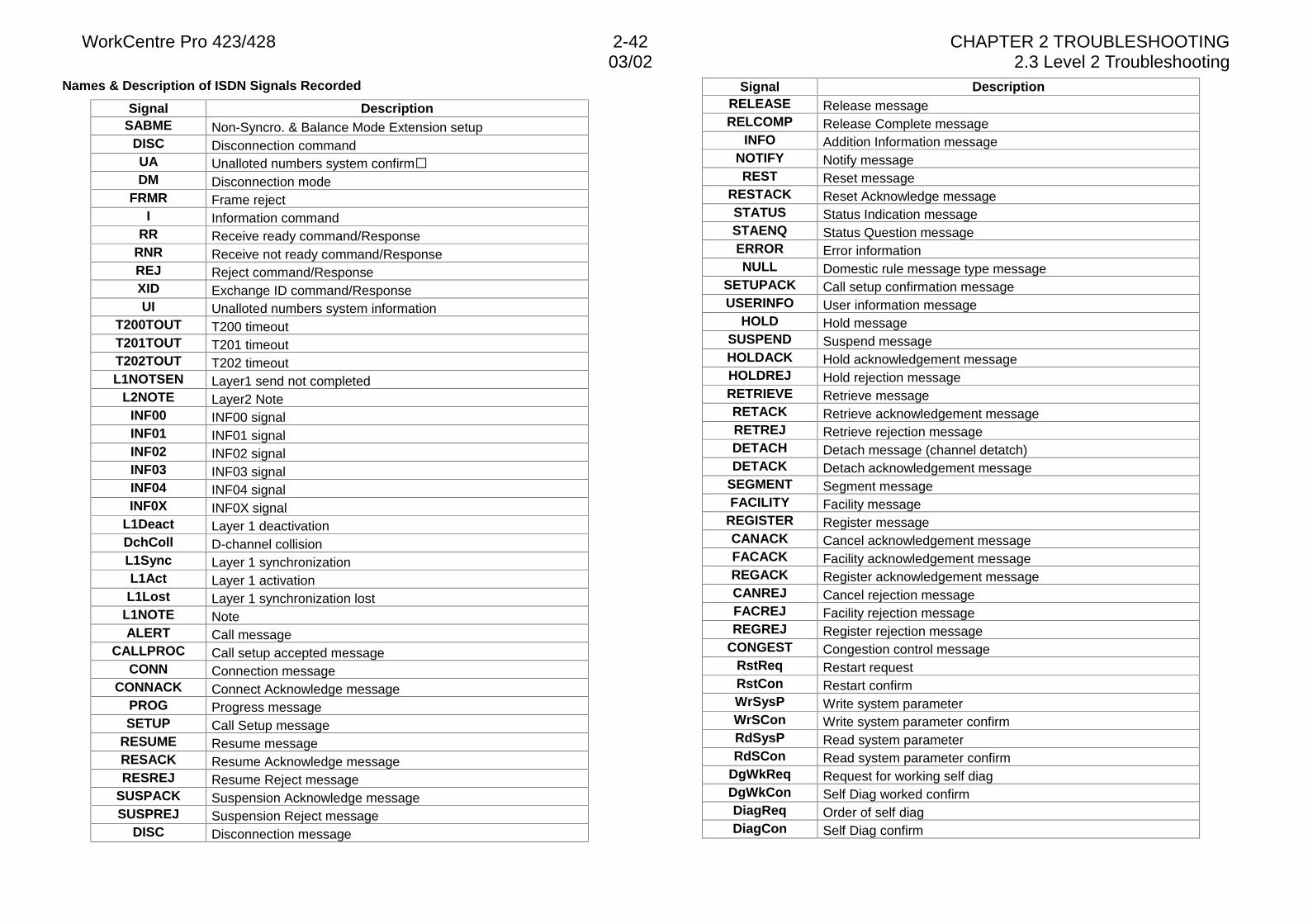
WorkCentre Pro 423/428 2-42 CHAPTER 2 TROUBLESHOOTING03/02 2.3 Level 2 Troubleshooting
Names & Description of ISDN Signals Recorded
Signal DescriptionSABME Non-Syncro. & Balance Mode Extension setup
DISC Disconnection commandUA Unalloted numbers system confirm�DM Disconnection mode
FRMR Frame rejectI Information command
RR Receive ready command/ResponseRNR Receive not ready command/ResponseREJ Reject command/ResponseXID Exchange ID command/ResponseUI Unalloted numbers system information
T200TOUT T200 timeoutT201TOUT T201 timeoutT202TOUT T202 timeoutL1NOTSEN Layer1 send not completed
L2NOTE Layer2 NoteINF00 INF00 signalINF01 INF01 signalINF02 INF02 signalINF03 INF03 signalINF04 INF04 signalINF0X INF0X signal
L1Deact Layer 1 deactivationDchColl D-channel collisionL1Sync Layer 1 synchronizationL1Act Layer 1 activationL1Lost Layer 1 synchronization lost
L1NOTE NoteALERT Call message
CALLPROC Call setup accepted messageCONN Connection message
CONNACK Connect Acknowledge messagePROG Progress messageSETUP Call Setup message
RESUME Resume messageRESACK Resume Acknowledge messageRESREJ Resume Reject message
SUSPACK Suspension Acknowledge messageSUSPREJ Suspension Reject message
DISC Disconnection message
Signal DescriptionRELEASE Release messageRELCOMP Release Complete message
INFO Addition Information messageNOTIFY Notify messageREST Reset message
RESTACK Reset Acknowledge messageSTATUS Status Indication messageSTAENQ Status Question messageERROR Error informationNULL Domestic rule message type message
SETUPACK Call setup confirmation messageUSERINFO User information message
HOLD Hold messageSUSPEND Suspend messageHOLDACK Hold acknowledgement messageHOLDREJ Hold rejection messageRETRIEVE Retrieve messageRETACK Retrieve acknowledgement messageRETREJ Retrieve rejection messageDETACH Detach message (channel detatch)DETACK Detach acknowledgement message
SEGMENT Segment messageFACILITY Facility message
REGISTER Register messageCANACK Cancel acknowledgement messageFACACK Facility acknowledgement messageREGACK Register acknowledgement messageCANREJ Cancel rejection messageFACREJ Facility rejection messageREGREJ Register rejection message
CONGEST Congestion control messageRstReq Restart requestRstCon Restart confirmWrSysP Write system parameterWrSCon Write system parameter confirmRdSysP Read system parameterRdSCon Read system parameter confirm
DgWkReq Request for working self diagDgWkCon Self Diag worked confirmDiagReq Order of self diagDiagCon Self Diag confirm
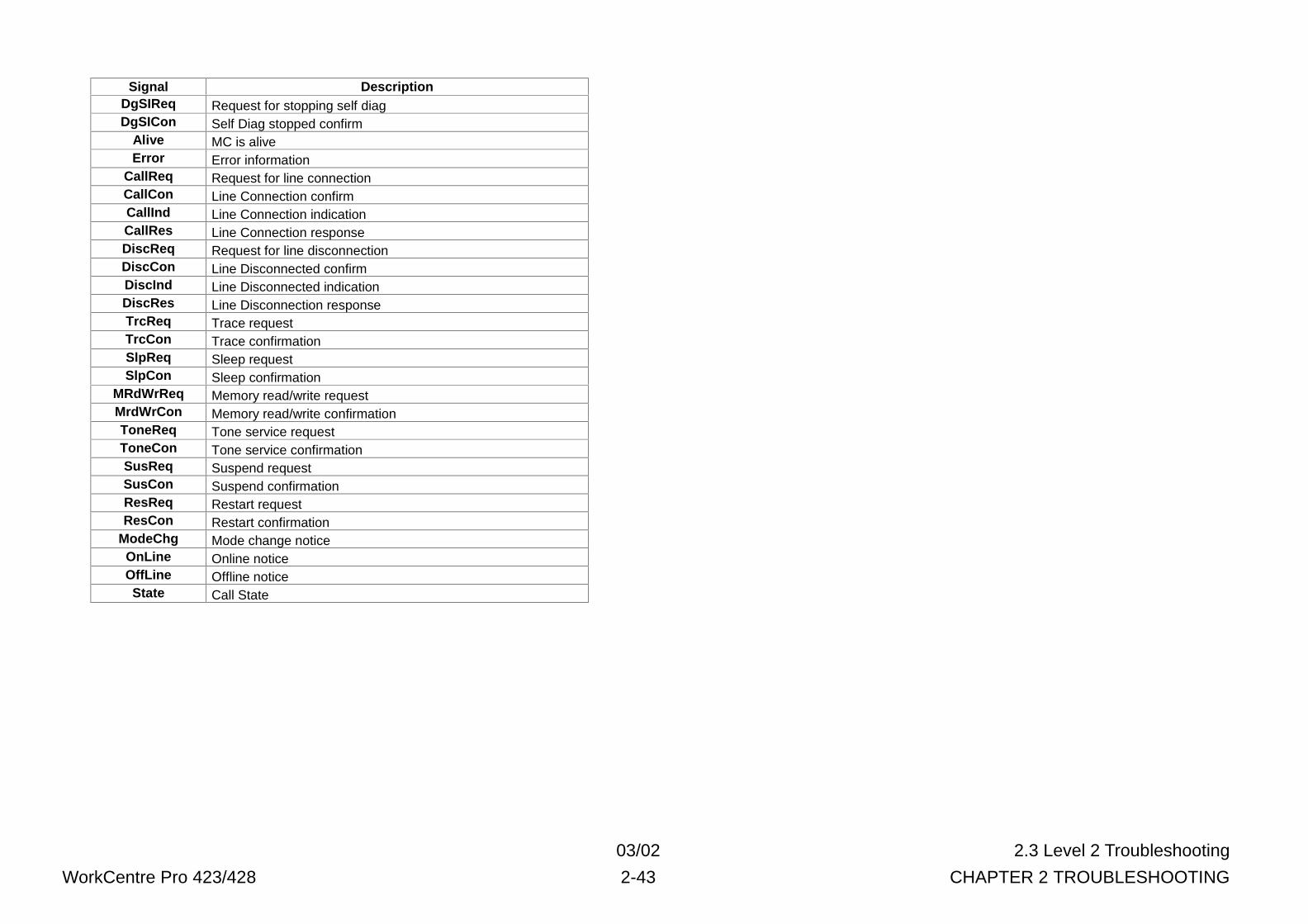
03/02 2.3 Level 2 Troubleshooting
WorkCentre Pro 423/428 2-43 CHAPTER 2 TROUBLESHOOTING
Signal DescriptionDgSIReq Request for stopping self diagDgSICon Self Diag stopped confirm
Alive MC is aliveError Error information
CallReq Request for line connectionCallCon Line Connection confirmCallInd Line Connection indicationCallRes Line Connection responseDiscReq Request for line disconnectionDiscCon Line Disconnected confirmDiscInd Line Disconnected indicationDiscRes Line Disconnection responseTrcReq Trace requestTrcCon Trace confirmationSlpReq Sleep requestSlpCon Sleep confirmation
MRdWrReq Memory read/write requestMrdWrCon Memory read/write confirmationToneReq Tone service requestToneCon Tone service confirmationSusReq Suspend requestSusCon Suspend confirmationResReq Restart requestResCon Restart confirmation
ModeChg Mode change noticeOnLine Online noticeOffLine Offline noticeState Call State
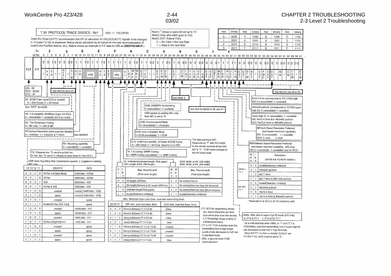
WorkCentre Pro 423/428 2-44 CHAPTER 2 TROUBLESHOOTING03/02 2-3 Level 2 Troubleshooting
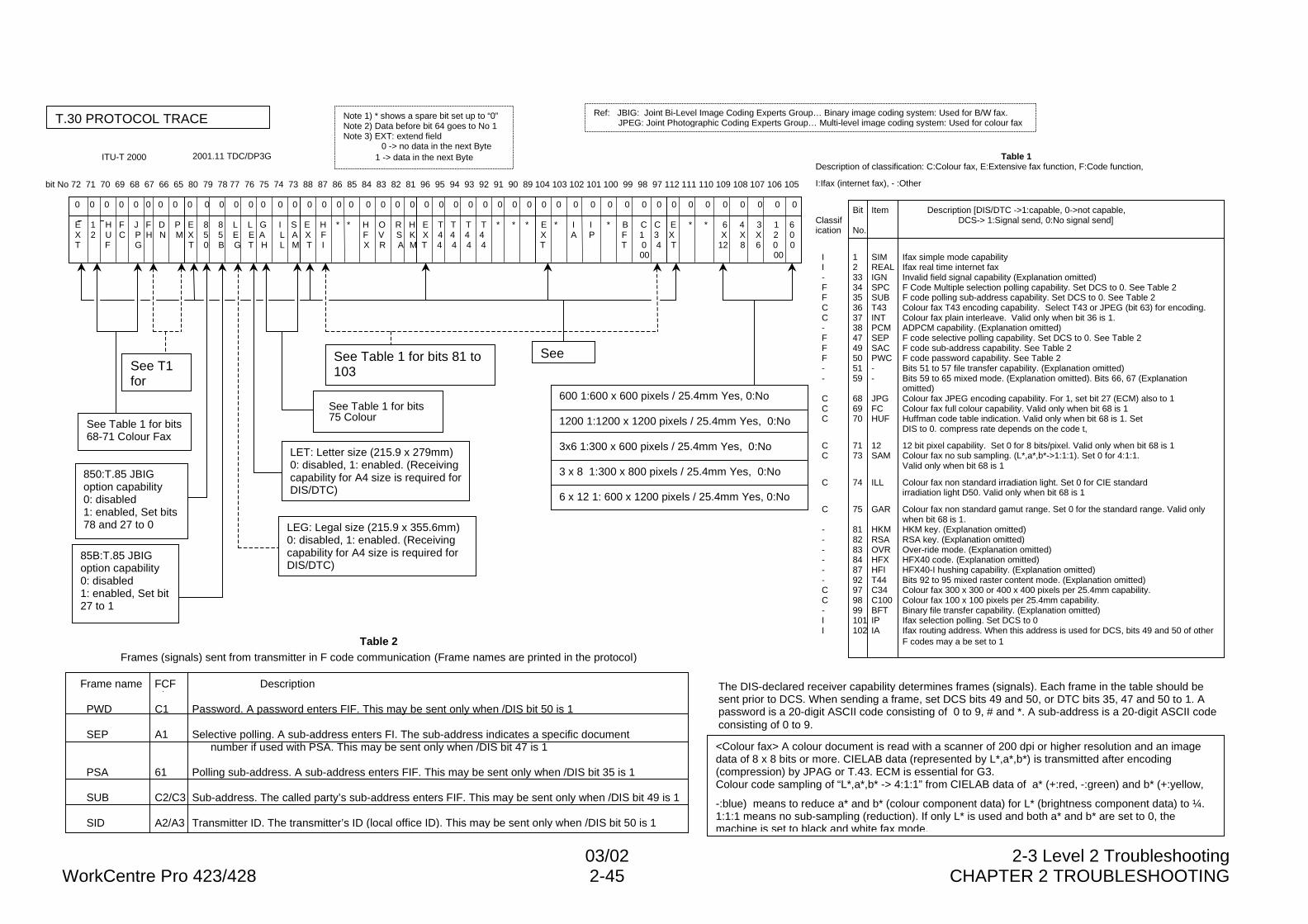
03/02 2-3 Level 2 TroubleshootingWorkCentre Pro 423/428 2-45 CHAPTER 2 TROUBLESHOOTING
T.30 PROTOCOL TRACE Note 1) * shows a spare bit set up to “0”Note 2) Data before bit 64 goes to No 1Note 3) EXT: extend field
0 -> no data in the next Byte 1 -> data in the next Byte
Ref: JBIG: Joint Bi-Level Image Coding Experts Group… Binary image coding system: Used for B/W fax. JPEG: Joint Photographic Coding Experts Group… Multi-level image coding system: Used for colour fax
bit No 72 71 70 69 68 67 66 65 80 79 78 77 76 75 74 73 88 87 86 85 84 83 82 81 96 95 94 93 92 91 90 89 104 103 102 101 100 99 98 97 112 111 110 109 108 107 106
0 0 0 0 0 0 0 0 0 0 0 0 0 0 0 0 0 0 0 0 0 0 0 0 0 0 0 0 0 0 0 0 0 0 0 0 0 0 0 0 0 0 0 0 0 0
E 1 H F J F D P E 8 8 L L G I S E H * * H O R H E T T T T * * * E * I I * B C C E * * 6 4 3 X 2 U C P H N M X 5 5 E E A L A X F F V S K X 4 4 4 4 X A P F 1 3 X X X X T F G T 0 B G T H L M T I X R A M T 4 4 4 4 T T 0 4 T 12 8 6 00 00
bit No 72 71 70 69 68 67 66 65 80 79 78 77 76 75 74 73 88 87 86 85 84 83 82 81 96 95 94 93 92 91 90 89 104 103 102 101 100 99 98 97 112 111 110 109 108 107 106 105
0 0 0 0 0 0 0 0 0 0 0 0 0 0 0 0 0 0 0 0 0 0 0 0 0 0 0 0 0 0 0 0 0 0 0 0 0 0 0 0 0 0 0 0 0 0 0 0
E 1 H F J F D P E 8 8 L L G I S E H * * H O R H E T T T T * * * E * I I * B C C E * * 6 4 3 1 6 X 2 U C P H N M X 5 5 E E A L A X F F V S K X 4 4 4 4 X A P F 1 3 X X X X 2 0 T F G T 0 B G T H L M T I X R A M T 4 4 4 4 T T 0 4 T 12 8 6 0 0 00 00
Table 1Description of classification: C:Colour fax, E:Extensive fax function, F:Code function,
I:Ifax (internet fax), - :Other
Bit Item Description [DIS/DTC ->1:capable, 0->not capable,Classif DCS-> 1:Signal send, 0:No signal send]ication No.
I 1 SIM Ifax simple mode capabilityI 2 REAL Ifax real time internet fax- 33 IGN Invalid field signal capability (Explanation omitted)F 34 SPC F Code Multiple selection polling capability. Set DCS to 0. See Table 2F 35 SUB F code polling sub-address capability. Set DCS to 0. See Table 2C 36 T43 Colour fax T43 encoding capability. Select T43 or JPEG (bit 63) for encoding.C 37 INT Colour fax plain interleave. Valid only when bit 36 is 1.- 38 PCM ADPCM capability. (Explanation omitted)F 47 SEP F code selective polling capability. Set DCS to 0. See Table 2F 49 SAC F code sub-address capability. See Table 2F 50 PWC F code password capability. See Table 2- 51 - Bits 51 to 57 file transfer capability. (Explanation omitted)- 59 - Bits 59 to 65 mixed mode. (Explanation omitted). Bits 66, 67 (Explanation
omitted)C 68 JPG Colour fax JPEG encoding capability. For 1, set bit 27 (ECM) also to 1C 69 FC Colour fax full colour capability. Valid only when bit 68 is 1C 70 HUF Huffman code table indication. Valid only when bit 68 is 1. Set
DIS to 0. compress rate depends on the code t,
C 71 12 12 bit pixel capability. Set 0 for 8 bits/pixel. Valid only when bit 68 is 1C 73 SAM Colour fax no sub sampling. (L*,a*,b*->1:1:1). Set 0 for 4:1:1.
Valid only when bit 68 is 1
C 74 ILL Colour fax non standard irradiation light. Set 0 for CIE standard irradiation light D50. Valid only when bit 68 is 1
C 75 GAR Colour fax non standard gamut range. Set 0 for the standard range. Valid only when bit 68 is 1.
- 81 HKM HKM key. (Explanation omitted)- 82 RSA RSA key. (Explanation omitted)- 83 OVR Over-ride mode. (Explanation omitted)- 84 HFX HFX40 code. (Explanation omitted)- 87 HFI HFX40-I hushing capability. (Explanation omitted)- 92 T44 Bits 92 to 95 mixed raster content mode. (Explanation omitted)C 97 C34 Colour fax 300 x 300 or 400 x 400 pixels per 25.4mm capability.C 98 C100 Colour fax 100 x 100 pixels per 25.4mm capability.- 99 BFT Binary file transfer capability. (Explanation omitted)I 101 IP Ifax selection polling. Set DCS to 0I 102 IA Ifax routing address. When this address is used for DCS, bits 49 and 50 of other
F codes may a be set to 1
ITU-T 2000 2001.11 TDC/DP3G
See T1for
850:T.85 JBIGoption capability0: disabled1: enabled, Set bits78 and 27 to 0
85B:T.85 JBIGoption capability0: disabled1: enabled, Set bit27 to 1
See Table 1 for bits 81 to103
See Table 1 for bits75 Colour
LET: Letter size (215.9 x 279mm)0: disabled, 1: enabled. (Receivingcapability for A4 size is required forDIS/DTC)
LEG: Legal size (215.9 x 355.6mm)0: disabled, 1: enabled. (Receivingcapability for A4 size is required forDIS/DTC)
See Table 1 for bits68-71 Colour Fax
See
600 1:600 x 600 pixels / 25.4mm Yes, 0:No
1200 1:1200 x 1200 pixels / 25.4mm Yes, 0:No
3x6 1:300 x 600 pixels / 25.4mm Yes, 0:No
3 x 8 1:300 x 800 pixels / 25.4mm Yes, 0:No
6 x 12 1: 600 x 1200 pixels / 25.4mm Yes, 0:No
Frame name FCF Description
PWD C1 Password. A password enters FIF. This may be sent only when /DIS bit 50 is 1
SEP A1 Selective polling. A sub-address enters FI. The sub-address indicates a specific documentnumber if used with PSA. This may be sent only when /DIS bit 47 is 1
PSA 61 Polling sub-address. A sub-address enters FIF. This may be sent only when /DIS bit 35 is 1
SUB C2/C3 Sub-address. The called party’s sub-address enters FIF. This may be sent only when /DIS bit 49 is 1
SID A2/A3 Transmitter ID. The transmitter’s ID (local office ID). This may be sent only when /DIS bit 50 is 1
The DIS-declared receiver capability determines frames (signals). Each frame in the table should besent prior to DCS. When sending a frame, set DCS bits 49 and 50, or DTC bits 35, 47 and 50 to 1. Apassword is a 20-digit ASCII code consisting of 0 to 9, # and *. A sub-address is a 20-digit ASCII codeconsisting of 0 to 9.
<Colour fax> A colour document is read with a scanner of 200 dpi or higher resolution and an imagedata of 8 x 8 bits or more. CIELAB data (represented by L*,a*,b*) is transmitted after encoding(compression) by JPAG or T.43. ECM is essential for G3.Colour code sampling of “L*,a*,b* -> 4:1:1” from CIELAB data of a* (+:red, -:green) and b* (+:yellow,
-:blue) means to reduce a* and b* (colour component data) for L* (brightness component data) to ¼.1:1:1 means no sub-sampling (reduction). If only L* is used and both a* and b* are set to 0, themachine is set to black and white fax mode.
Table 2Frames (signals) sent from transmitter in F code communication (Frame names are printed in the protocol)
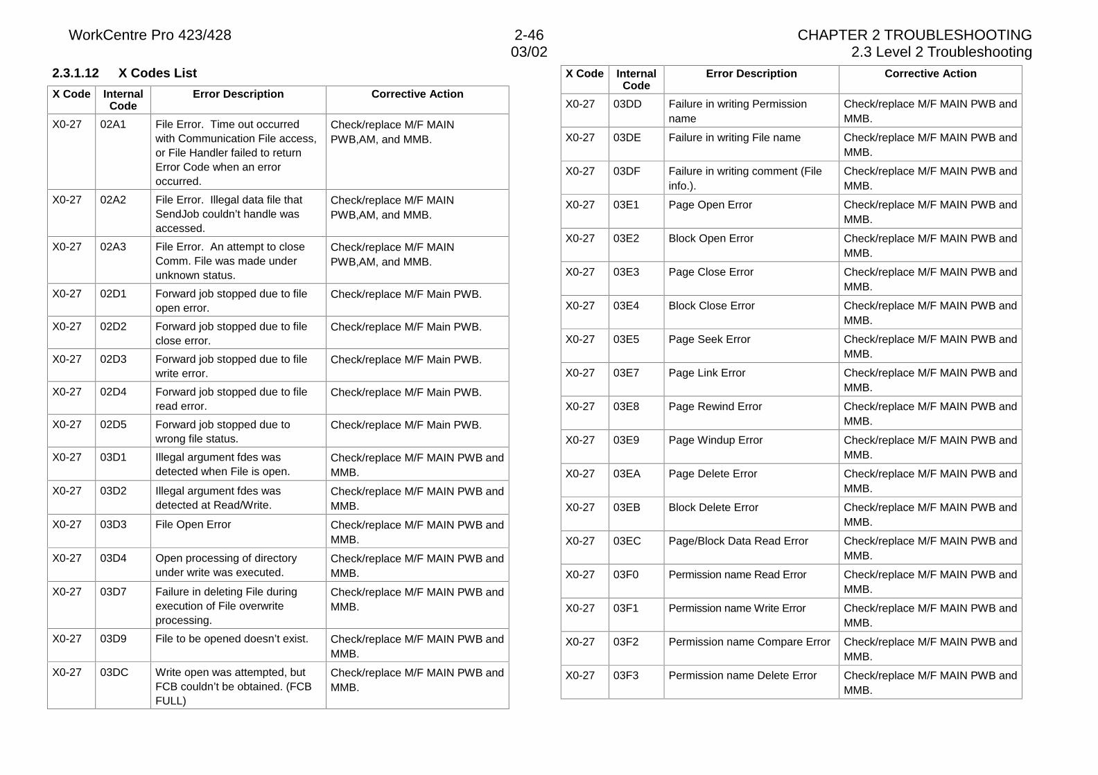
WorkCentre Pro 423/428 2-46 CHAPTER 2 TROUBLESHOOTING03/02 2.3 Level 2 Troubleshooting
2.3.1.12 X Codes List
X Code InternalCode
Error Description Corrective Action
X0-27 02A1 File Error. Time out occurredwith Communication File access,or File Handler failed to returnError Code when an erroroccurred.
Check/replace M/F MAINPWB,AM, and MMB.
X0-27 02A2 File Error. Illegal data file thatSendJob couldn’t handle wasaccessed.
Check/replace M/F MAINPWB,AM, and MMB.
X0-27 02A3 File Error. An attempt to closeComm. File was made underunknown status.
Check/replace M/F MAINPWB,AM, and MMB.
X0-27 02D1 Forward job stopped due to fileopen error.
Check/replace M/F Main PWB.
X0-27 02D2 Forward job stopped due to fileclose error.
Check/replace M/F Main PWB.
X0-27 02D3 Forward job stopped due to filewrite error.
Check/replace M/F Main PWB.
X0-27 02D4 Forward job stopped due to fileread error.
Check/replace M/F Main PWB.
X0-27 02D5 Forward job stopped due towrong file status.
Check/replace M/F Main PWB.
X0-27 03D1 Illegal argument fdes wasdetected when File is open.
Check/replace M/F MAIN PWB andMMB.
X0-27 03D2 Illegal argument fdes wasdetected at Read/Write.
Check/replace M/F MAIN PWB andMMB.
X0-27 03D3 File Open Error Check/replace M/F MAIN PWB andMMB.
X0-27 03D4 Open processing of directoryunder write was executed.
Check/replace M/F MAIN PWB andMMB.
X0-27 03D7 Failure in deleting File duringexecution of File overwriteprocessing.
Check/replace M/F MAIN PWB andMMB.
X0-27 03D9 File to be opened doesn’t exist. Check/replace M/F MAIN PWB andMMB.
X0-27 03DC Write open was attempted, butFCB couldn’t be obtained. (FCBFULL)
Check/replace M/F MAIN PWB andMMB.
X Code InternalCode
Error Description Corrective Action
X0-27 03DD Failure in writing Permissionname
Check/replace M/F MAIN PWB andMMB.
X0-27 03DE Failure in writing File name Check/replace M/F MAIN PWB andMMB.
X0-27 03DF Failure in writing comment (Fileinfo.).
Check/replace M/F MAIN PWB andMMB.
X0-27 03E1 Page Open Error Check/replace M/F MAIN PWB andMMB.
X0-27 03E2 Block Open Error Check/replace M/F MAIN PWB andMMB.
X0-27 03E3 Page Close Error Check/replace M/F MAIN PWB andMMB.
X0-27 03E4 Block Close Error Check/replace M/F MAIN PWB andMMB.
X0-27 03E5 Page Seek Error Check/replace M/F MAIN PWB andMMB.
X0-27 03E7 Page Link Error Check/replace M/F MAIN PWB andMMB.
X0-27 03E8 Page Rewind Error Check/replace M/F MAIN PWB andMMB.
X0-27 03E9 Page Windup Error Check/replace M/F MAIN PWB andMMB.
X0-27 03EA Page Delete Error Check/replace M/F MAIN PWB andMMB.
X0-27 03EB Block Delete Error Check/replace M/F MAIN PWB andMMB.
X0-27 03EC Page/Block Data Read Error Check/replace M/F MAIN PWB andMMB.
X0-27 03F0 Permission name Read Error Check/replace M/F MAIN PWB andMMB.
X0-27 03F1 Permission name Write Error Check/replace M/F MAIN PWB andMMB.
X0-27 03F2 Permission name Compare Error Check/replace M/F MAIN PWB andMMB.
X0-27 03F3 Permission name Delete Error Check/replace M/F MAIN PWB andMMB.
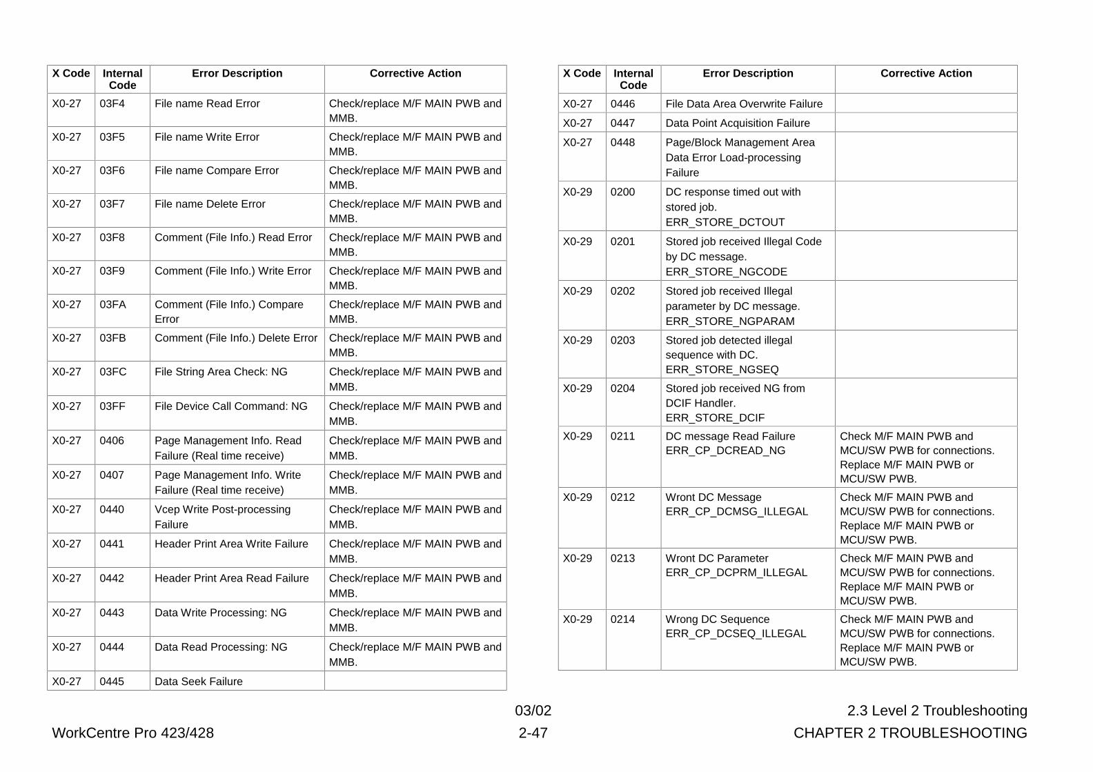
03/02 2.3 Level 2 Troubleshooting
WorkCentre Pro 423/428 2-47 CHAPTER 2 TROUBLESHOOTING
X Code InternalCode
Error Description Corrective Action
X0-27 03F4 File name Read Error Check/replace M/F MAIN PWB andMMB.
X0-27 03F5 File name Write Error Check/replace M/F MAIN PWB andMMB.
X0-27 03F6 File name Compare Error Check/replace M/F MAIN PWB andMMB.
X0-27 03F7 File name Delete Error Check/replace M/F MAIN PWB andMMB.
X0-27 03F8 Comment (File Info.) Read Error Check/replace M/F MAIN PWB andMMB.
X0-27 03F9 Comment (File Info.) Write Error Check/replace M/F MAIN PWB andMMB.
X0-27 03FA Comment (File Info.) CompareError
Check/replace M/F MAIN PWB andMMB.
X0-27 03FB Comment (File Info.) Delete Error Check/replace M/F MAIN PWB andMMB.
X0-27 03FC File String Area Check: NG Check/replace M/F MAIN PWB andMMB.
X0-27 03FF File Device Call Command: NG Check/replace M/F MAIN PWB andMMB.
X0-27 0406 Page Management Info. ReadFailure (Real time receive)
Check/replace M/F MAIN PWB andMMB.
X0-27 0407 Page Management Info. WriteFailure (Real time receive)
Check/replace M/F MAIN PWB andMMB.
X0-27 0440 Vcep Write Post-processingFailure
Check/replace M/F MAIN PWB andMMB.
X0-27 0441 Header Print Area Write Failure Check/replace M/F MAIN PWB andMMB.
X0-27 0442 Header Print Area Read Failure Check/replace M/F MAIN PWB andMMB.
X0-27 0443 Data Write Processing: NG Check/replace M/F MAIN PWB andMMB.
X0-27 0444 Data Read Processing: NG Check/replace M/F MAIN PWB andMMB.
X0-27 0445 Data Seek Failure
X Code InternalCode
Error Description Corrective Action
X0-27 0446 File Data Area Overwrite Failure
X0-27 0447 Data Point Acquisition Failure
X0-27 0448 Page/Block Management AreaData Error Load-processingFailure
X0-29 0200 DC response timed out withstored job.ERR_STORE_DCTOUT
X0-29 0201 Stored job received Illegal Codeby DC message.ERR_STORE_NGCODE
X0-29 0202 Stored job received Illegalparameter by DC message.ERR_STORE_NGPARAM
X0-29 0203 Stored job detected illegalsequence with DC.ERR_STORE_NGSEQ
X0-29 0204 Stored job received NG fromDCIF Handler.ERR_STORE_DCIF
X0-29 0211 DC message Read FailureERR_CP_DCREAD_NG
Check M/F MAIN PWB andMCU/SW PWB for connections.Replace M/F MAIN PWB orMCU/SW PWB.
X0-29 0212 Wront DC MessageERR_CP_DCMSG_ILLEGAL
Check M/F MAIN PWB andMCU/SW PWB for connections.Replace M/F MAIN PWB orMCU/SW PWB.
X0-29 0213 Wront DC ParameterERR_CP_DCPRM_ILLEGAL
Check M/F MAIN PWB andMCU/SW PWB for connections.Replace M/F MAIN PWB orMCU/SW PWB.
X0-29 0214 Wrong DC SequenceERR_CP_DCSEQ_ILLEGAL
Check M/F MAIN PWB andMCU/SW PWB for connections.Replace M/F MAIN PWB orMCU/SW PWB.
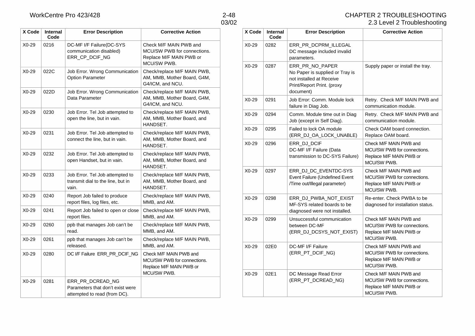
WorkCentre Pro 423/428 2-48 CHAPTER 2 TROUBLESHOOTING03/02 2.3 Level 2 Troubleshooting
X Code InternalCode
Error Description Corrective Action
X0-29 0216 DC-MF I/F Failure(DC-SYScommunication disabled)ERR_CP_DCIF_NG
Check M/F MAIN PWB andMCU/SW PWB for connections.Replace M/F MAIN PWB orMCU/SW PWB.
X0-29 022C Job Error. Wrong CommunicationOption Parameter
Check/replace M/F MAIN PWB,AM, MMB, Mother Board, G4M,G4/ICM, and NCU.
X0-29 022D Job Error. Wrong CommunicationData Parameter
Check/replace M/F MAIN PWB,AM, MMB, Mother Board, G4M,G4/ICM, and NCU.
X0-29 0230 Job Error. Tel Job attempted toopen the line, but in vain.
Check/replace M/F MAIN PWB,AM, MMB, Mother Board, andHANDSET.
X0-29 0231 Job Error. Tel Job attempted toconnect the line, but in vain.
Check/replace M/F MAIN PWB,AM, MMB, Mother Board, andHANDSET.
X0-29 0232 Job Error. Tel Job attempted toopen Handset, but in vain.
Check/replace M/F MAIN PWB,AM, MMB, Mother Board, andHANDSET.
X0-29 0233 Job Error. Tel Job attempted totransmit dial to the line, but invain.
Check/replace M/F MAIN PWB,AM, MMB, Mother Board, andHANDSET.
X0-29 0240 Report Job failed to producereport files, log files, etc.
Check/replace M/F MAIN PWB,MMB, and AM.
X0-29 0241 Report Job failed to open or closereport files.
Check/replace M/F MAIN PWB,MMB, and AM.
X0-29 0260 ppb that manages Job can’t beread.
Check/replace M/F MAIN PWB,MMB, and AM.
X0-29 0261 ppb that manages Job can’t bereleased.
Check/replace M/F MAIN PWB,MMB, and AM.
X0-29 0280 DC I/F Failure ERR_PR_DCIF_NG Check M/F MAIN PWB andMCU/SW PWB for connections.Replace M/F MAIN PWB orMCU/SW PWB.
X0-29 0281 ERR_PR_DCREAD_NGParameters that don’t exist wereattempted to read (from DC).
X Code InternalCode
Error Description Corrective Action
X0-29 0282 ERR_PR_DCPRM_ILLEGALDC message included invalidparameters.
X0-29 0287 ERR_PR_NO_PAPERNo Paper is supplied or Tray isnot installed at ReceivePrint/Report Print. (proxydocument)
Supply paper or install the tray.
X0-29 0291 Job Error: Comm. Module lockfailure in Diag Job.
Retry. Check M/F MAIN PWB andcommunication module.
X0-29 0294 Comm. Module time out in DiagJob (except in Self Diag).
Retry. Check M/F MAIN PWB andcommunication module.
X0-29 0295 Failed to lock OA module(ERR_DJ_OA_LOCK_UNABLE)
Check OAM board connection.Replace OAM board.
X0-29 0296 ERR_DJ_DCIFDC-MF I/F Failure (Datatransmission to DC-SYS Failure)
Check M/F MAIN PWB andMCU/SW PWB for connections.Replace M/F MAIN PWB orMCU/SW PWB.
X0-29 0297 ERR_DJ_DC_EVENTDC-SYSEvent Failure (Undefined Event/Time out/Illegal parameter)
Check M/F MAIN PWB andMCU/SW PWB for connections.Replace M/F MAIN PWB orMCU/SW PWB.
X0-29 0298 ERR_DJ_PWBA_NOT_EXISTMF-SYS related boards to bediagnosed were not installed.
Re-enter. Check PWBA to bediagnosed for installation status.
X0-29 0299 Unsuccessful communicationbetween DC-MF(ERR_DJ_DCSYS_NOT_EXIST)
Check M/F MAIN PWB andMCU/SW PWB for connections.Replace M/F MAIN PWB orMCU/SW PWB.
X0-29 02E0 DC-MF I/F Failure(ERR_PT_DCIF_NG)
Check M/F MAIN PWB andMCU/SW PWB for connections.Replace M/F MAIN PWB orMCU/SW PWB.
X0-29 02E1 DC Message Read Error(ERR_PT_DCREAD_NG)
Check M/F MAIN PWB andMCU/SW PWB for connections.Replace M/F MAIN PWB orMCU/SW PWB.
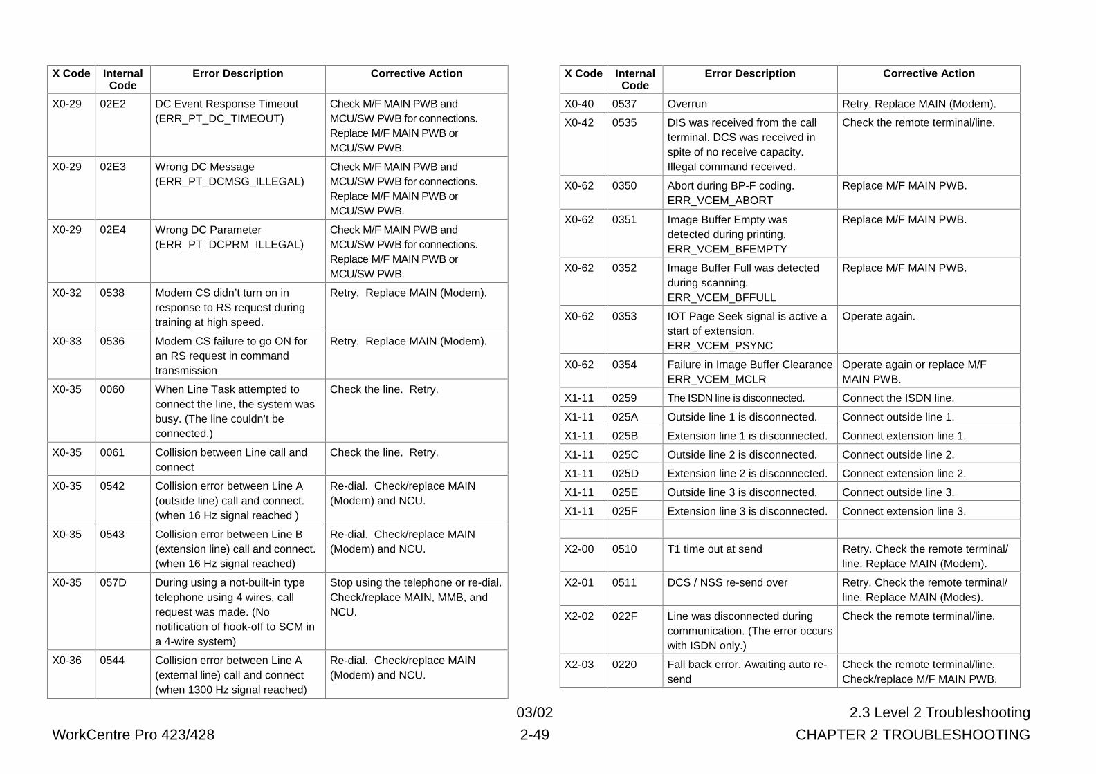
03/02 2.3 Level 2 Troubleshooting
WorkCentre Pro 423/428 2-49 CHAPTER 2 TROUBLESHOOTING
X Code InternalCode
Error Description Corrective Action
X0-29 02E2 DC Event Response Timeout(ERR_PT_DC_TIMEOUT)
Check M/F MAIN PWB andMCU/SW PWB for connections.Replace M/F MAIN PWB orMCU/SW PWB.
X0-29 02E3 Wrong DC Message(ERR_PT_DCMSG_ILLEGAL)
Check M/F MAIN PWB andMCU/SW PWB for connections.Replace M/F MAIN PWB orMCU/SW PWB.
X0-29 02E4 Wrong DC Parameter(ERR_PT_DCPRM_ILLEGAL)
Check M/F MAIN PWB andMCU/SW PWB for connections.Replace M/F MAIN PWB orMCU/SW PWB.
X0-32 0538 Modem CS didn’t turn on inresponse to RS request duringtraining at high speed.
Retry. Replace MAIN (Modem).
X0-33 0536 Modem CS failure to go ON foran RS request in commandtransmission
Retry. Replace MAIN (Modem).
X0-35 0060 When Line Task attempted toconnect the line, the system wasbusy. (The line couldn’t beconnected.)
Check the line. Retry.
X0-35 0061 Collision between Line call andconnect
Check the line. Retry.
X0-35 0542 Collision error between Line A(outside line) call and connect.(when 16 Hz signal reached )
Re-dial. Check/replace MAIN(Modem) and NCU.
X0-35 0543 Collision error between Line B(extension line) call and connect.(when 16 Hz signal reached)
Re-dial. Check/replace MAIN(Modem) and NCU.
X0-35 057D During using a not-built-in typetelephone using 4 wires, callrequest was made. (Nonotification of hook-off to SCM ina 4-wire system)
Stop using the telephone or re-dial.Check/replace MAIN, MMB, andNCU.
X0-36 0544 Collision error between Line A(external line) call and connect(when 1300 Hz signal reached)
Re-dial. Check/replace MAIN(Modem) and NCU.
X Code InternalCode
Error Description Corrective Action
X0-40 0537 Overrun Retry. Replace MAIN (Modem).
X0-42 0535 DIS was received from the callterminal. DCS was received inspite of no receive capacity.Illegal command received.
Check the remote terminal/line.
X0-62 0350 Abort during BP-F coding.ERR_VCEM_ABORT
Replace M/F MAIN PWB.
X0-62 0351 Image Buffer Empty wasdetected during printing.ERR_VCEM_BFEMPTY
Replace M/F MAIN PWB.
X0-62 0352 Image Buffer Full was detectedduring scanning.ERR_VCEM_BFFULL
Replace M/F MAIN PWB.
X0-62 0353 IOT Page Seek signal is active astart of extension.ERR_VCEM_PSYNC
Operate again.
X0-62 0354 Failure in Image Buffer ClearanceERR_VCEM_MCLR
Operate again or replace M/FMAIN PWB.
X1-11 0259 The ISDN line is disconnected. Connect the ISDN line.
X1-11 025A Outside line 1 is disconnected. Connect outside line 1.
X1-11 025B Extension line 1 is disconnected. Connect extension line 1.
X1-11 025C Outside line 2 is disconnected. Connect outside line 2.
X1-11 025D Extension line 2 is disconnected. Connect extension line 2.
X1-11 025E Outside line 3 is disconnected. Connect outside line 3.
X1-11 025F Extension line 3 is disconnected. Connect extension line 3.
X2-00 0510 T1 time out at send Retry. Check the remote terminal/line. Replace MAIN (Modem).
X2-01 0511 DCS / NSS re-send over Retry. Check the remote terminal/line. Replace MAIN (Modes).
X2-02 022F Line was disconnected duringcommunication. (The error occurswith ISDN only.)
Check the remote terminal/line.
X2-03 0220 Fall back error. Awaiting auto re-send
Check the remote terminal/line.Check/replace M/F MAIN PWB.
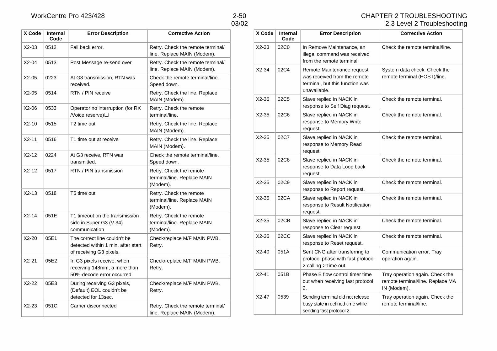
WorkCentre Pro 423/428 2-50 CHAPTER 2 TROUBLESHOOTING03/02 2.3 Level 2 Troubleshooting
X Code InternalCode
Error Description Corrective Action
X2-03 0512 Fall back error. Retry. Check the remote terminal/line. Replace MAIN (Modem).
X2-04 0513 Post Message re-send over Retry. Check the remote terminal/line. Replace MAIN (Modem).
X2-05 0223 At G3 transmission, RTN wasreceived.
Check the remote terminal/line.Speed down.
X2-05 0514 RTN / PIN receive Retry. Check the line. ReplaceMAIN (Modem).
X2-06 0533 Operator no interruption (for RX/Voice reserve)�
Retry. Check the remoteterminal/line.
X2-10 0515 T2 time out Retry. Check the line. ReplaceMAIN (Modem).
X2-11 0516 T1 time out at receive Retry. Check the line. ReplaceMAIN (Modem).
X2-12 0224 At G3 receive, RTN wastransmitted.
Check the remote terminal/line.Speed down.
X2-12 0517 RTN / PIN transmission Retry. Check the remoteterminal/line. Replace MAIN(Modem).
X2-13 0518 T5 time out Retry. Check the remoteterminal/line. Replace MAIN(Modem).
X2-14 051E T1 timeout on the transmissionside in Super G3 (V.34)communication
Retry. Check the remoteterminal/line. Replace MAIN(Modem).
X2-20 05E1 The correct line couldn’t bedetected within 1 min. after startof receiving G3 pixels.
Check/replace M/F MAIN PWB.Retry.
X2-21 05E2 In G3 pixels receive, whenreceiving 148mm, a more than50%-decode error occurred.
Check/replace M/F MAIN PWB.Retry.
X2-22 05E3 During receiving G3 pixels,(Default) EOL couldn’t bedetected for 13sec.
Check/replace M/F MAIN PWB.Retry.
X2-23 051C Carrier disconnected Retry. Check the remote terminal/line. Replace MAIN (Modem).
X Code InternalCode
Error Description Corrective Action
X2-33 02C0 In Remove Maintenance, anillegal command was receivedfrom the remote terminal.
Check the remote terminal/line.
X2-34 02C4 Remote Maintenance requestwas received from the remoteterminal, but this function wasunavailable.
System data check. Check theremote terminal (HOST)/line.
X2-35 02C5 Slave replied in NACK inresponse to Self Diag request.
Check the remote terminal.
X2-35 02C6 Slave replied in NACK inresponse to Memory Writerequest.
Check the remote terminal.
X2-35 02C7 Slave replied in NACK inresponse to Memory Readrequest.
Check the remote terminal.
X2-35 02C8 Slave replied in NACK inresponse to Data Loop backrequest.
Check the remote terminal.
X2-35 02C9 Slave replied in NACK inresponse to Report request.
Check the remote terminal.
X2-35 02CA Slave replied in NACK inresponse to Result Notificationrequest.
Check the remote terminal.
X2-35 02CB Slave replied in NACK inresponse to Clear request.
Check the remote terminal.
X2-35 02CC Slave replied in NACK inresponse to Reset request.
Check the remote terminal.
X2-40 051A Sent CNG after transferring toprotocol phase with fast protocol2 calling->Time out.
Communication error. Trayoperation again.
X2-41 051B Phase B flow control timer timeout when receiving fast protocol2.
Tray operation again. Check theremote terminal/line. Replace MAIN (Modem).
X2-47 0539 Sending terminal did not releasebusy state in defined time whilesending fast protocol 2.
Tray operation again. Check theremote terminal/line.
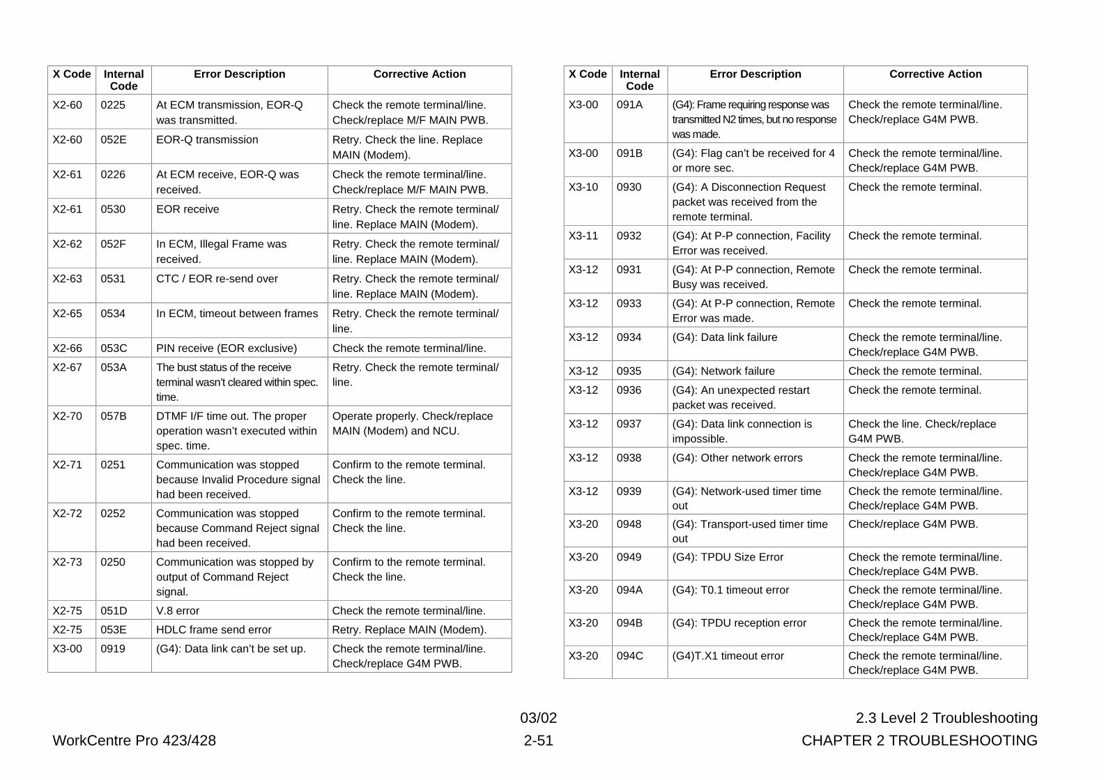
03/02 2.3 Level 2 Troubleshooting
WorkCentre Pro 423/428 2-51 CHAPTER 2 TROUBLESHOOTING
X Code InternalCode
Error Description Corrective Action
X2-60 0225 At ECM transmission, EOR-Qwas transmitted.
Check the remote terminal/line.Check/replace M/F MAIN PWB.
X2-60 052E EOR-Q transmission Retry. Check the line. ReplaceMAIN (Modem).
X2-61 0226 At ECM receive, EOR-Q wasreceived.
Check the remote terminal/line.Check/replace M/F MAIN PWB.
X2-61 0530 EOR receive Retry. Check the remote terminal/line. Replace MAIN (Modem).
X2-62 052F In ECM, Illegal Frame wasreceived.
Retry. Check the remote terminal/line. Replace MAIN (Modem).
X2-63 0531 CTC / EOR re-send over Retry. Check the remote terminal/line. Replace MAIN (Modem).
X2-65 0534 In ECM, timeout between frames Retry. Check the remote terminal/line.
X2-66 053C PIN receive (EOR exclusive) Check the remote terminal/line.
X2-67 053A The bust status of the receiveterminal wasn’t cleared within spec.time.
Retry. Check the remote terminal/line.
X2-70 057B DTMF I/F time out. The properoperation wasn’t executed withinspec. time.
Operate properly. Check/replaceMAIN (Modem) and NCU.
X2-71 0251 Communication was stoppedbecause Invalid Procedure signalhad been received.
Confirm to the remote terminal.Check the line.
X2-72 0252 Communication was stoppedbecause Command Reject signalhad been received.
Confirm to the remote terminal.Check the line.
X2-73 0250 Communication was stopped byoutput of Command Rejectsignal.
Confirm to the remote terminal.Check the line.
X2-75 051D V.8 error Check the remote terminal/line.
X2-75 053E HDLC frame send error Retry. Replace MAIN (Modem).
X3-00 0919 (G4): Data link can’t be set up. Check the remote terminal/line.Check/replace G4M PWB.
X Code InternalCode
Error Description Corrective Action
X3-00 091A (G4): Frame requiring response wastransmitted N2 times, but no responsewas made.
Check the remote terminal/line.Check/replace G4M PWB.
X3-00 091B (G4): Flag can’t be received for 4or more sec.
Check the remote terminal/line.Check/replace G4M PWB.
X3-10 0930 (G4): A Disconnection Requestpacket was received from theremote terminal.
Check the remote terminal.
X3-11 0932 (G4): At P-P connection, FacilityError was received.
Check the remote terminal.
X3-12 0931 (G4): At P-P connection, RemoteBusy was received.
Check the remote terminal.
X3-12 0933 (G4): At P-P connection, RemoteError was made.
Check the remote terminal.
X3-12 0934 (G4): Data link failure Check the remote terminal/line.Check/replace G4M PWB.
X3-12 0935 (G4): Network failure Check the remote terminal.
X3-12 0936 (G4): An unexpected restartpacket was received.
Check the remote terminal.
X3-12 0937 (G4): Data link connection isimpossible.
Check the line. Check/replaceG4M PWB.
X3-12 0938 (G4): Other network errors Check the remote terminal/line.Check/replace G4M PWB.
X3-12 0939 (G4): Network-used timer timeout
Check the remote terminal/line.Check/replace G4M PWB.
X3-20 0948 (G4): Transport-used timer timeout
Check/replace G4M PWB.
X3-20 0949 (G4): TPDU Size Error Check the remote terminal/line.Check/replace G4M PWB.
X3-20 094A (G4): T0.1 timeout error Check the remote terminal/line.Check/replace G4M PWB.
X3-20 094B (G4): TPDU reception error Check the remote terminal/line.Check/replace G4M PWB.
X3-20 094C (G4)T.X1 timeout error Check the remote terminal/line.Check/replace G4M PWB.
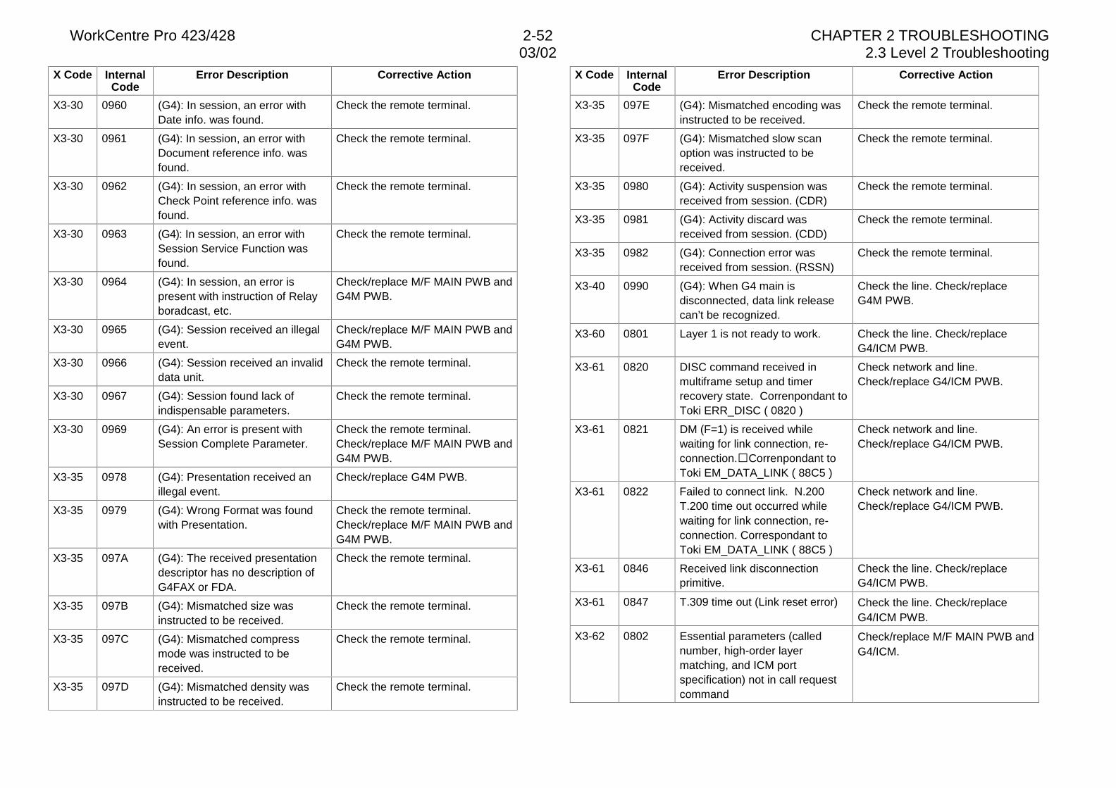
WorkCentre Pro 423/428 2-52 CHAPTER 2 TROUBLESHOOTING03/02 2.3 Level 2 Troubleshooting
X Code InternalCode
Error Description Corrective Action
X3-30 0960 (G4): In session, an error withDate info. was found.
Check the remote terminal.
X3-30 0961 (G4): In session, an error withDocument reference info. wasfound.
Check the remote terminal.
X3-30 0962 (G4): In session, an error withCheck Point reference info. wasfound.
Check the remote terminal.
X3-30 0963 (G4): In session, an error withSession Service Function wasfound.
Check the remote terminal.
X3-30 0964 (G4): In session, an error ispresent with instruction of Relayboradcast, etc.
Check/replace M/F MAIN PWB andG4M PWB.
X3-30 0965 (G4): Session received an illegalevent.
Check/replace M/F MAIN PWB andG4M PWB.
X3-30 0966 (G4): Session received an invaliddata unit.
Check the remote terminal.
X3-30 0967 (G4): Session found lack ofindispensable parameters.
Check the remote terminal.
X3-30 0969 (G4): An error is present withSession Complete Parameter.
Check the remote terminal.Check/replace M/F MAIN PWB andG4M PWB.
X3-35 0978 (G4): Presentation received anillegal event.
Check/replace G4M PWB.
X3-35 0979 (G4): Wrong Format was foundwith Presentation.
Check the remote terminal.Check/replace M/F MAIN PWB andG4M PWB.
X3-35 097A (G4): The received presentationdescriptor has no description ofG4FAX or FDA.
Check the remote terminal.
X3-35 097B (G4): Mismatched size wasinstructed to be received.
Check the remote terminal.
X3-35 097C (G4): Mismatched compressmode was instructed to bereceived.
Check the remote terminal.
X3-35 097D (G4): Mismatched density wasinstructed to be received.
Check the remote terminal.
X Code InternalCode
Error Description Corrective Action
X3-35 097E (G4): Mismatched encoding wasinstructed to be received.
Check the remote terminal.
X3-35 097F (G4): Mismatched slow scanoption was instructed to bereceived.
Check the remote terminal.
X3-35 0980 (G4): Activity suspension wasreceived from session. (CDR)
Check the remote terminal.
X3-35 0981 (G4): Activity discard wasreceived from session. (CDD)
Check the remote terminal.
X3-35 0982 (G4): Connection error wasreceived from session. (RSSN)
Check the remote terminal.
X3-40 0990 (G4): When G4 main isdisconnected, data link releasecan’t be recognized.
Check the line. Check/replaceG4M PWB.
X3-60 0801 Layer 1 is not ready to work. Check the line. Check/replaceG4/ICM PWB.
X3-61 0820 DISC command received inmultiframe setup and timerrecovery state. Correnpondant toToki ERR_DISC ( 0820 )
Check network and line.Check/replace G4/ICM PWB.
X3-61 0821 DM (F=1) is received whilewaiting for link connection, re-connection.�Correnpondant toToki EM_DATA_LINK ( 88C5 )
Check network and line.Check/replace G4/ICM PWB.
X3-61 0822 Failed to connect link. N.200T.200 time out occurred whilewaiting for link connection, re-connection. Correspondant toToki EM_DATA_LINK ( 88C5 )
Check network and line.Check/replace G4/ICM PWB.
X3-61 0846 Received link disconnectionprimitive.
Check the line. Check/replaceG4/ICM PWB.
X3-61 0847 T.309 time out (Link reset error) Check the line. Check/replaceG4/ICM PWB.
X3-62 0802 Essential parameters (callednumber, high-order layermatching, and ICM portspecification) not in call requestcommand
Check/replace M/F MAIN PWB andG4/ICM.
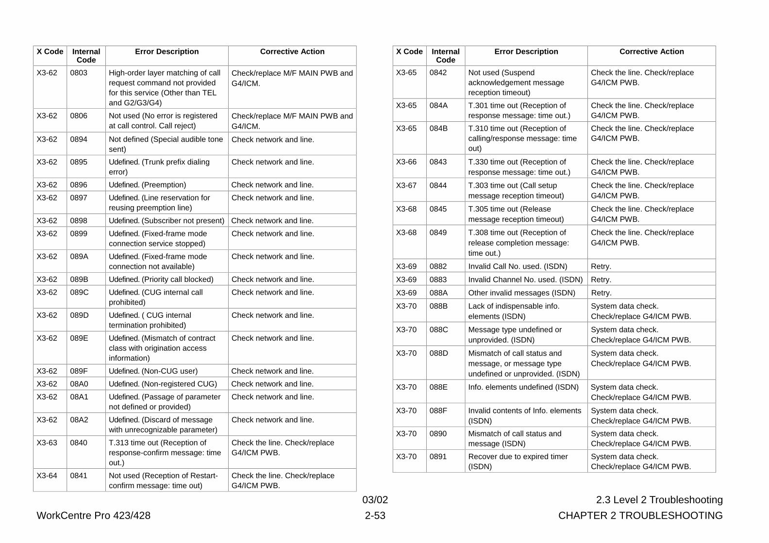
03/02 2.3 Level 2 Troubleshooting
WorkCentre Pro 423/428 2-53 CHAPTER 2 TROUBLESHOOTING
X Code InternalCode
Error Description Corrective Action
X3-62 0803 High-order layer matching of callrequest command not providedfor this service (Other than TELand G2/G3/G4)
Check/replace M/F MAIN PWB andG4/ICM.
X3-62 0806 Not used (No error is registeredat call control. Call reject)
Check/replace M/F MAIN PWB andG4/ICM.
X3-62 0894 Not defined (Special audible tonesent)
Check network and line.
X3-62 0895 Udefined. (Trunk prefix dialingerror)
Check network and line.
X3-62 0896 Udefined. (Preemption) Check network and line.
X3-62 0897 Udefined. (Line reservation forreusing preemption line)
Check network and line.
X3-62 0898 Udefined. (Subscriber not present) Check network and line.
X3-62 0899 Udefined. (Fixed-frame modeconnection service stopped)
Check network and line.
X3-62 089A Udefined. (Fixed-frame modeconnection not available)
Check network and line.
X3-62 089B Udefined. (Priority call blocked) Check network and line.
X3-62 089C Udefined. (CUG internal callprohibited)
Check network and line.
X3-62 089D Udefined. ( CUG internaltermination prohibited)
Check network and line.
X3-62 089E Udefined. (Mismatch of contractclass with origination accessinformation)
Check network and line.
X3-62 089F Udefined. (Non-CUG user) Check network and line.
X3-62 08A0 Udefined. (Non-registered CUG) Check network and line.
X3-62 08A1 Udefined. (Passage of parameternot defined or provided)
Check network and line.
X3-62 08A2 Udefined. (Discard of messagewith unrecognizable parameter)
Check network and line.
X3-63 0840 T.313 time out (Reception ofresponse-confirm message: timeout.)
Check the line. Check/replaceG4/ICM PWB.
X3-64 0841 Not used (Reception of Restart-confirm message: time out)
Check the line. Check/replaceG4/ICM PWB.
X Code InternalCode
Error Description Corrective Action
X3-65 0842 Not used (Suspendacknowledgement messagereception timeout)
Check the line. Check/replaceG4/ICM PWB.
X3-65 084A T.301 time out (Reception ofresponse message: time out.)
Check the line. Check/replaceG4/ICM PWB.
X3-65 084B T.310 time out (Reception ofcalling/response message: timeout)
Check the line. Check/replaceG4/ICM PWB.
X3-66 0843 T.330 time out (Reception ofresponse message: time out.)
Check the line. Check/replaceG4/ICM PWB.
X3-67 0844 T.303 time out (Call setupmessage reception timeout)
Check the line. Check/replaceG4/ICM PWB.
X3-68 0845 T.305 time out (Releasemessage reception timeout)
Check the line. Check/replaceG4/ICM PWB.
X3-68 0849 T.308 time out (Reception ofrelease completion message:time out.)
Check the line. Check/replaceG4/ICM PWB.
X3-69 0882 Invalid Call No. used. (ISDN) Retry.
X3-69 0883 Invalid Channel No. used. (ISDN) Retry.
X3-69 088A Other invalid messages (ISDN) Retry.
X3-70 088B Lack of indispensable info.elements (ISDN)
System data check.Check/replace G4/ICM PWB.
X3-70 088C Message type undefined orunprovided. (ISDN)
System data check.Check/replace G4/ICM PWB.
X3-70 088D Mismatch of call status andmessage, or message typeundefined or unprovided. (ISDN)
System data check.Check/replace G4/ICM PWB.
X3-70 088E Info. elements undefined (ISDN) System data check.Check/replace G4/ICM PWB.
X3-70 088F Invalid contents of Info. elements(ISDN)
System data check.Check/replace G4/ICM PWB.
X3-70 0890 Mismatch of call status andmessage (ISDN)
System data check.Check/replace G4/ICM PWB.
X3-70 0891 Recover due to expired timer(ISDN)
System data check.Check/replace G4/ICM PWB.
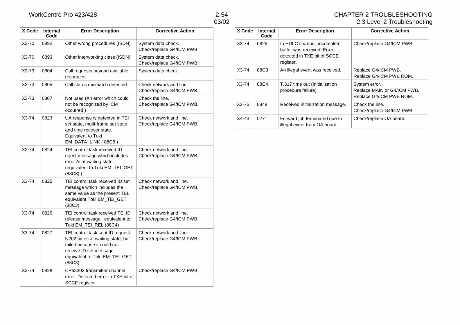
WorkCentre Pro 423/428 2-54 CHAPTER 2 TROUBLESHOOTING03/02 2.3 Level 2 Troubleshooting
X Code InternalCode
Error Description Corrective Action
X3-70 0892 Other wrong procedures (ISDN) System data check.Check/replace G4/ICM PWB.
X3-70 0893 Other interworking class (ISDN) System data check.Check/replace G4/ICM PWB.
X3-73 0804 Call requests beyond availableresources
System data check.
X3-73 0805 Call status mismatch detected Check network and line.Check/replace G4/ICM PWB.
X3-73 0807 Not used (An error which couldnot be recognized by ICMoccurred.)
Check the line.Check/replace G4/ICM PWB.
X3-74 0823 UA response is detected in TEIset state, multi-frame set stateand time recover state.Equivalent to TokiEM_DATA_LINK ( 88C5 )
Check network and line.Check/replace G4/ICM PWB.
X3-74 0824 TEI control task received IDreject message which includeserror Ai at waiting state.(equivalent to Toki EM_TEI_GET(88C3) )
Check network and line.Check/replace G4/ICM PWB.
X3-74 0825 TEI control task received ID setmessage which includes thesame value as the present TEI.equivalent Toki EM_TEI_GET(88C3)
Check network and line.Check/replace G4/ICM PWB.
X3-74 0826 TEI control task received TEI IDrelease message. equivalent toToki EM_TEI_REL (88C4)
Check network and line.Check/replace G4/ICM PWB.
X3-74 0827 TEI control task sent ID requestN202 times at waiting state, butfailed because it could notreceive ID set message.equivalent to Toki EM_TEI_GET(88C3)
Check network and line.Check/replace G4/ICM PWB.
X3-74 0828 CP68302 transmitter channelerror. Detected error in TXE bit ofSCCE register.
Check/replace G4/ICM PWB.
X Code InternalCode
Error Description Corrective Action
X3-74 0829 In HDLC channel, incompletebuffer was received. Errordetected in TXE bit of SCCEregister.
Check/replace G4/ICM PWB.
X3-74 88C3 An illegal event was received. Replace G4/ICM PWB.Replace G4/ICM PWB ROM.
X3-74 88C4 T.317 time out (Initializationprocedure failure)
System error.Replace MAIN or G4/ICM PWB.Replace G4/ICM PWB ROM.
X3-75 0848 Received initialization message. Check the line.Check/replace G4/ICM PWB.
X4-43 0271 Forward job terminated due toillegal event from OA board.
Check/replace OA board.
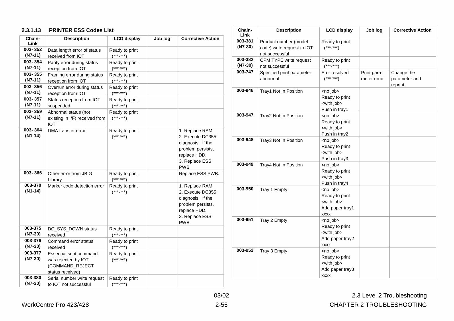
03/02 2.3 Level 2 Troubleshooting
WorkCentre Pro 423/428 2-55 CHAPTER 2 TROUBLESHOOTING
2.3.1.13 PRINTER ESS Codes List
Chain-Link
Description LCD display Job log Corrective Action
003- 352(N7-11)
Data length error of statusreceived from IOT
Ready to print (***-***)
003- 354(N7-11)
Parity error during statusreception from IOT
Ready to print (***-***)
003- 355(N7-11)
Framing error during statusreception from IOT
Ready to print (***-***)
003- 356(N7-11)
Overrun error during statusreception from IOT
Ready to print (***-***)
003- 357(N7-11)
Status reception from IOTsuspended
Ready to print (***-***)
003- 359(N7-11)
Abnormal status (notexisting in I/F) received fromIOT
Ready to print (***-***)
003- 364(N1-14)
DMA transfer error Ready to print (***-***)
1. Replace RAM.2. Execute DC355diagnosis. If theproblem persists,replace HDD.3. Replace ESSPWB.
003- 366 Other error from JBIGLibrary
Ready to print (***-***)
Replace ESS PWB.
003-370(N1-14)
Marker code detection error Ready to print (***-***)
1. Replace RAM.2. Execute DC355diagnosis. If theproblem persists,replace HDD.3. Replace ESSPWB.
003-375(N7-30)
DC_SYS_DOWN statusreceived
Ready to print (***-***)
003-376(N7-30)
Command error statusreceived
Ready to print (***-***)
003-377(N7-30)
Essential sent commandwas rejected by IOT(COMMAND_REJECTstatus received)
Ready to print (***-***)
003-380(N7-30)
Serial number write requestto IOT not successful
Ready to print (***-***)
Chain-Link
Description LCD display Job log Corrective Action
003-381(N7-30)
Product number (modelcode) write request to IOTnot successful
Ready to print (***-***)
003-382(N7-30)
CPM TYPE write requestnot successful
Ready to print (***-***)
003-747 Specified print parameterabnormal
Eror resolved (***-***)
Print para-meter error
Change theparameter andreprint.
003-946 Tray1 Not In Position <no job>Ready to print<with job>Push in tray1
003-947 Tray2 Not In Position <no job>Ready to print<with job>Push in tray2
003-948 Tray3 Not In Position <no job>Ready to print<with job>Push in tray3
003-949 Tray4 Not In Position <no job>Ready to print<with job>Push in tray4
003-950 Tray 1 Empty <no job>Ready to print<with job>Add paper tray1xxxx
003-951 Tray 2 Empty <no job>Ready to print<with job>Add paper tray2xxxx
003-952 Tray 3 Empty <no job>Ready to print<with job>Add paper tray3xxxx
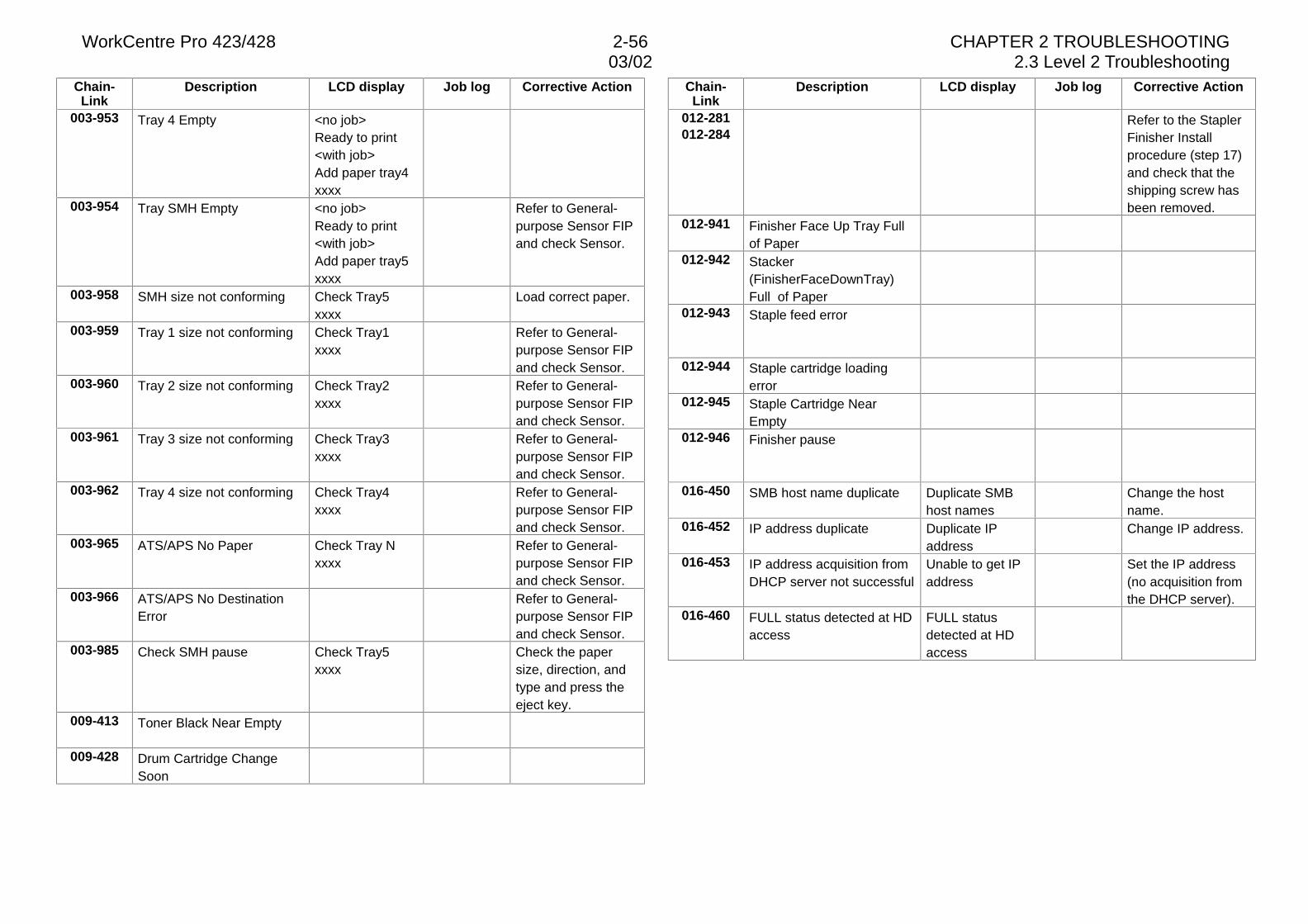
WorkCentre Pro 423/428 2-56 CHAPTER 2 TROUBLESHOOTING03/02 2.3 Level 2 Troubleshooting
Chain-Link
Description LCD display Job log Corrective Action
003-953 Tray 4 Empty <no job>Ready to print<with job>Add paper tray4xxxx
003-954 Tray SMH Empty <no job>Ready to print<with job>Add paper tray5xxxx
Refer to General-purpose Sensor FIPand check Sensor.
003-958 SMH size not conforming Check Tray5xxxx
Load correct paper.
003-959 Tray 1 size not conforming Check Tray1xxxx
Refer to General-purpose Sensor FIPand check Sensor.
003-960 Tray 2 size not conforming Check Tray2xxxx
Refer to General-purpose Sensor FIPand check Sensor.
003-961 Tray 3 size not conforming Check Tray3xxxx
Refer to General-purpose Sensor FIPand check Sensor.
003-962 Tray 4 size not conforming Check Tray4xxxx
Refer to General-purpose Sensor FIPand check Sensor.
003-965 ATS/APS No Paper Check Tray Nxxxx
Refer to General-purpose Sensor FIPand check Sensor.
003-966 ATS/APS No DestinationError
Refer to General-purpose Sensor FIPand check Sensor.
003-985 Check SMH pause Check Tray5xxxx
Check the papersize, direction, andtype and press theeject key.
009-413 Toner Black Near Empty
009-428 Drum Cartridge ChangeSoon
Chain-Link
Description LCD display Job log Corrective Action
012-281012-284
Refer to the StaplerFinisher Installprocedure (step 17)and check that theshipping screw hasbeen removed.
012-941 Finisher Face Up Tray Fullof Paper
012-942 Stacker(FinisherFaceDownTray)Full of Paper
012-943 Staple feed error
012-944 Staple cartridge loadingerror
012-945 Staple Cartridge NearEmpty
012-946 Finisher pause
016-450 SMB host name duplicate Duplicate SMBhost names
Change the hostname.
016-452 IP address duplicate Duplicate IPaddress
Change IP address.
016-453 IP address acquisition fromDHCP server not successful
Unable to get IPaddress
Set the IP address(no acquisition fromthe DHCP server).
016-460 FULL status detected at HDaccess
FULL statusdetected at HDaccess
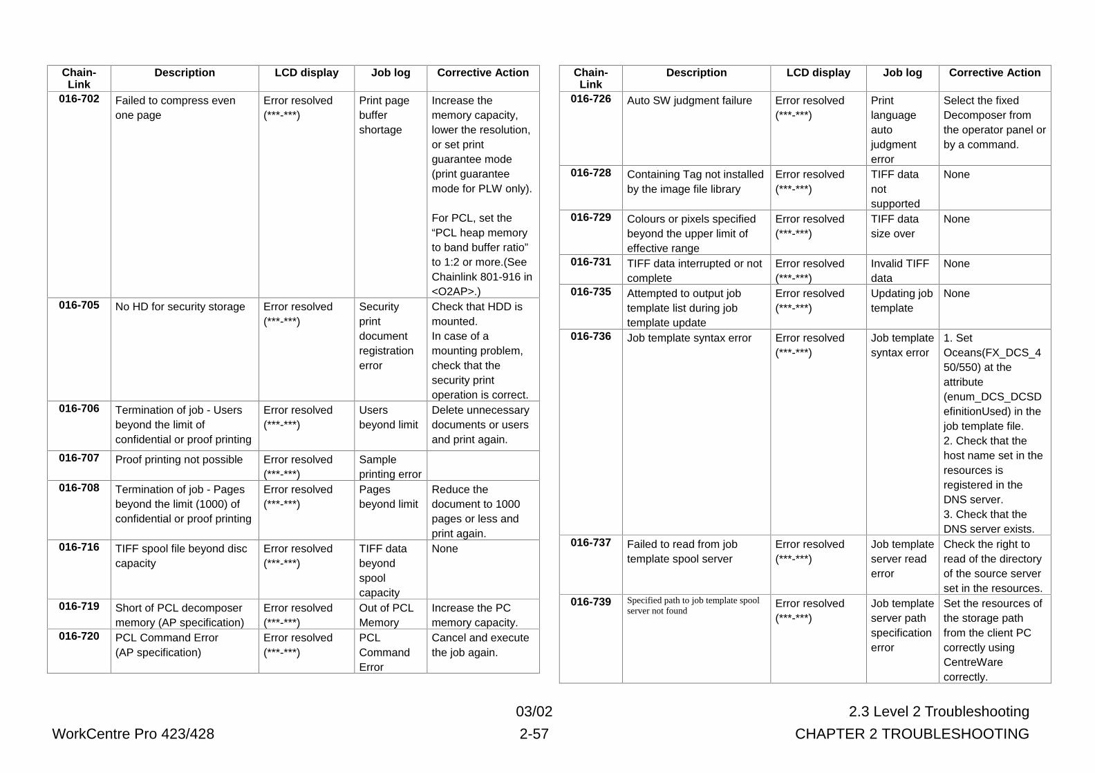
03/02 2.3 Level 2 Troubleshooting
WorkCentre Pro 423/428 2-57 CHAPTER 2 TROUBLESHOOTING
Chain-Link
Description LCD display Job log Corrective Action
016-702 Failed to compress evenone page
Error resolved(***-***)
Print pagebuffershortage
Increase thememory capacity,lower the resolution,or set printguarantee mode(print guaranteemode for PLW only).
For PCL, set the“PCL heap memoryto band buffer ratio”to 1:2 or more.(SeeChainlink 801-916 in<O2AP>.)
016-705 No HD for security storage Error resolved(***-***)
Securityprintdocumentregistrationerror
Check that HDD ismounted.In case of amounting problem,check that thesecurity printoperation is correct.
016-706 Termination of job - Usersbeyond the limit ofconfidential or proof printing
Error resolved(***-***)
Usersbeyond limit
Delete unnecessarydocuments or usersand print again.
016-707 Proof printing not possible Error resolved(***-***)
Sampleprinting error
016-708 Termination of job - Pagesbeyond the limit (1000) ofconfidential or proof printing
Error resolved(***-***)
Pagesbeyond limit
Reduce thedocument to 1000pages or less andprint again.
016-716 TIFF spool file beyond disccapacity
Error resolved(***-***)
TIFF databeyondspoolcapacity
None
016-719 Short of PCL decomposermemory (AP specification)
Error resolved(***-***)
Out of PCLMemory
Increase the PCmemory capacity.
016-720 PCL Command Error(AP specification)
Error resolved(***-***)
PCLCommandError
Cancel and executethe job again.
Chain-Link
Description LCD display Job log Corrective Action
016-726 Auto SW judgment failure Error resolved(***-***)
Printlanguageautojudgmenterror
Select the fixedDecomposer fromthe operator panel orby a command.
016-728 Containing Tag not installedby the image file library
Error resolved(***-***)
TIFF datanotsupported
None
016-729 Colours or pixels specifiedbeyond the upper limit ofeffective range
Error resolved(***-***)
TIFF datasize over
None
016-731 TIFF data interrupted or notcomplete
Error resolved(***-***)
Invalid TIFFdata
None
016-735 Attempted to output jobtemplate list during jobtemplate update
Error resolved(***-***)
Updating jobtemplate
None
016-736 Job template syntax error Error resolved(***-***)
Job templatesyntax error
1. SetOceans(FX_DCS_450/550) at theattribute(enum_DCS_DCSDefinitionUsed) in thejob template file.2. Check that thehost name set in theresources isregistered in theDNS server.3. Check that theDNS server exists.
016-737 Failed to read from jobtemplate spool server
Error resolved(***-***)
Job templateserver readerror
Check the right toread of the directoryof the source serverset in the resources.
016-739 Specified path to job template spoolserver not found
Error resolved(***-***)
Job templateserver pathspecificationerror
Set the resources ofthe storage pathfrom the client PCcorrectly usingCentreWarecorrectly.
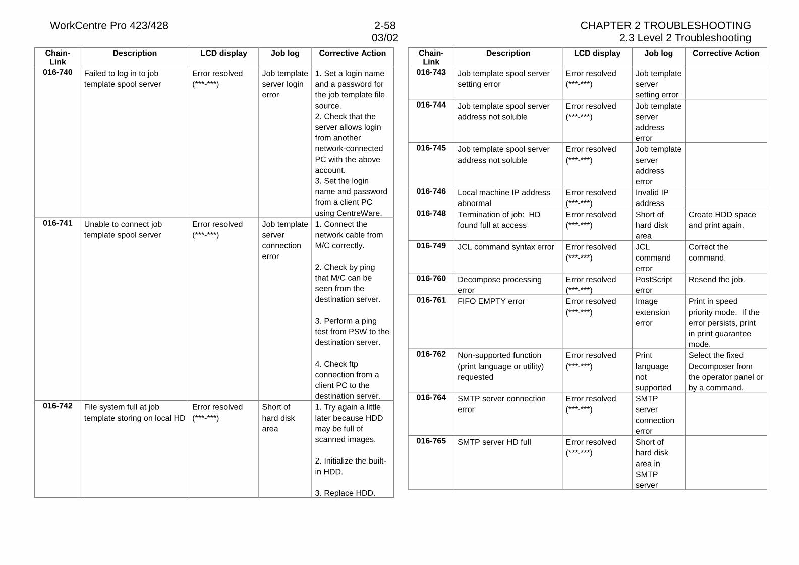
WorkCentre Pro 423/428 2-58 CHAPTER 2 TROUBLESHOOTING03/02 2.3 Level 2 Troubleshooting
Chain-Link
Description LCD display Job log Corrective Action
016-740 Failed to log in to jobtemplate spool server
Error resolved(***-***)
Job templateserver loginerror
1. Set a login nameand a password forthe job template filesource.2. Check that theserver allows loginfrom anothernetwork-connectedPC with the aboveaccount.3. Set the loginname and passwordfrom a client PCusing CentreWare.
016-741 Unable to connect jobtemplate spool server
Error resolved(***-***)
Job templateserverconnectionerror
1. Connect thenetwork cable fromM/C correctly.
2. Check by pingthat M/C can beseen from thedestination server.
3. Perform a pingtest from PSW to thedestination server.
4. Check ftpconnection from aclient PC to thedestination server.
016-742 File system full at jobtemplate storing on local HD
Error resolved(***-***)
Short ofhard diskarea
1. Try again a littlelater because HDDmay be full ofscanned images.
2. Initialize the built-in HDD.
3. Replace HDD.
Chain-Link
Description LCD display Job log Corrective Action
016-743 Job template spool serversetting error
Error resolved(***-***)
Job templateserversetting error
016-744 Job template spool serveraddress not soluble
Error resolved(***-***)
Job templateserveraddresserror
016-745 Job template spool serveraddress not soluble
Error resolved(***-***)
Job templateserveraddresserror
016-746 Local machine IP addressabnormal
Error resolved(***-***)
Invalid IPaddress
016-748 Termination of job: HDfound full at access
Error resolved(***-***)
Short ofhard diskarea
Create HDD spaceand print again.
016-749 JCL command syntax error Error resolved(***-***)
JCLcommanderror
Correct thecommand.
016-760 Decompose processingerror
Error resolved(***-***)
PostScripterror
Resend the job.
016-761 FIFO EMPTY error Error resolved(***-***)
Imageextensionerror
Print in speedpriority mode. If theerror persists, printin print guaranteemode.
016-762 Non-supported function(print language or utility)requested
Error resolved(***-***)
Printlanguagenotsupported
Select the fixedDecomposer fromthe operator panel orby a command.
016-764 SMTP server connectionerror
Error resolved(***-***)
SMTPserverconnectionerror
016-765 SMTP server HD full Error resolved(***-***)
Short ofhard diskarea inSMTPserver
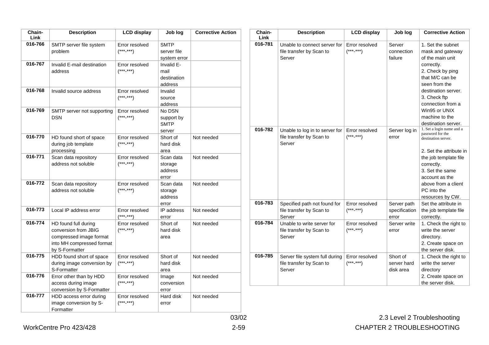
03/02 2.3 Level 2 Troubleshooting
WorkCentre Pro 423/428 2-59 CHAPTER 2 TROUBLESHOOTING
Chain-Link
Description LCD display Job log Corrective Action
016-766 SMTP server file systemproblem
Error resolved(***-***)
SMTPserver filesystem error
016-767 Invalid E-mail destinationaddress
Error resolved(***-***)
Invalid E-maildestinationaddress
016-768 Invalid source address Error resolved(***-***)
Invalidsourceaddress
016-769 SMTP server not supportingDSN
Error resolved(***-***)
No DSNsupport bySMTPserver
016-770 HD found short of spaceduring job templateprocessing
Error resolved(***-***)
Short ofhard diskarea
Not needed
016-771 Scan data repositoryaddress not soluble
Error resolved(***-***)
Scan datastorageaddresserror
Not needed
016-772 Scan data repositoryaddress not soluble
Error resolved(***-***)
Scan datastorageaddresserror
Not needed
016-773 Local IP address error Error resolved(***-***)
IP addresserror
Not needed
016-774 HD found full duringconversion from JBIGcompressed image formatinto MH compressed formatby S-Formatter
Error resolved(***-***)
Short ofhard diskarea
Not needed
016-775 HDD found short of spaceduring image conversion byS-Formatter
Error resolved(***-***)
Short ofhard diskarea
Not needed
016-776 Error other than by HDDaccess during imageconversion by S-Formatter
Error resolved(***-***)
Imageconversionerror
Not needed
016-777 HDD access error duringimage conversion by S-Formatter
Error resolved(***-***)
Hard diskerror
Not needed
Chain-Link
Description LCD display Job log Corrective Action
016-781 Unable to connect server forfile transfer by Scan toServer
Error resolved(***-***)
Serverconnectionfailure
1. Set the subnetmask and gatewayof the main unitcorrectly.2. Check by pingthat M/C can beseen from thedestination server.3. Check ftpconnection from aWin95 or UNIXmachine to thedestination server.
016-782 Unable to log in to server forfile transfer by Scan toServer
Error resolved(***-***)
Server log inerror
1. Set a login name and apassword for thedestination server.
2. Set the attribute inthe job template filecorrectly.3. Set the sameaccount as theabove from a clientPC into theresources by CW.
016-783 Specified path not found forfile transfer by Scan toServer
Error resolved(***-***)
Server pathspecificationerror
Set the attribute inthe job template filecorrectly.
016-784 Unable to write server forfile transfer by Scan toServer
Error resolved(***-***)
Server writeerror
1. Check the right towrite the serverdirectory.2. Create space onthe server disk.
016-785 Server file system full duringfile transfer by Scan toServer
Error resolved(***-***)
Short ofserver harddisk area
1. Check the right towrite the serverdirectory2. Create space onthe server disk.
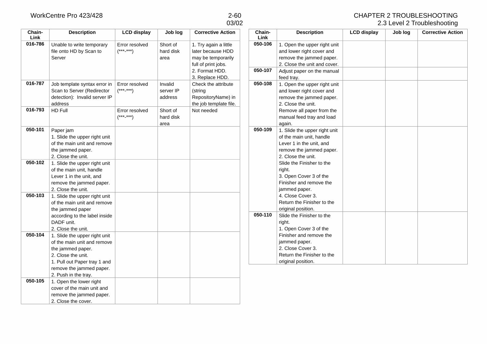
WorkCentre Pro 423/428 2-60 CHAPTER 2 TROUBLESHOOTING03/02 2.3 Level 2 Troubleshooting
Chain-Link
Description LCD display Job log Corrective Action
016-786 Unable to write temporaryfile onto HD by Scan toServer
Error resolved(***-***)
Short ofhard diskarea
1. Try again a littlelater because HDDmay be temporarilyfull of print jobs.2. Format HDD.3. Replace HDD.
016-787 Job template syntax error inScan to Server (Redirectordetection): Invalid server IPaddress
Error resolved(***-***)
Invalidserver IPaddress
Check the attribute(stringRepositoryName) inthe job template file.
016-793 HD Full Error resolved(***-***)
Short ofhard diskarea
Not needed
050-101 Paper jam1. Slide the upper right unitof the main unit and removethe jammed paper.2. Close the unit.
050-102 1. Slide the upper right unitof the main unit, handleLever 1 in the unit, andremove the jammed paper.2. Close the unit.
050-103 1. Slide the upper right unitof the main unit and removethe jammed paperaccording to the label insideDADF unit.2. Close the unit.
050-104 1. Slide the upper right unitof the main unit and removethe jammed paper.2. Close the unit.1. Pull out Paper tray 1 andremove the jammed paper.2. Push in the tray.
050-105 1. Open the lower rightcover of the main unit andremove the jammed paper.2. Close the cover.
Chain-Link
Description LCD display Job log Corrective Action
050-106 1. Open the upper right unitand lower right cover andremove the jammed paper.2. Close the unit and cover.
050-107 Adjust paper on the manualfeed tray.
050-108 1. Open the upper right unitand lower right cover andremove the jammed paper.2. Close the unit.Remove all paper from themanual feed tray and loadagain.
050-109 1. Slide the upper right unitof the main unit, handleLever 1 in the unit, andremove the jammed paper.2. Close the unit.Slide the Finisher to theright.3. Open Cover 3 of theFinisher and remove thejammed paper.4. Close Cover 3.Return the Finisher to theoriginal position.
050-110 Slide the Finisher to theright.1. Open Cover 3 of theFinisher and remove thejammed paper.2. Close Cover 3.Return the Finisher to theoriginal position.
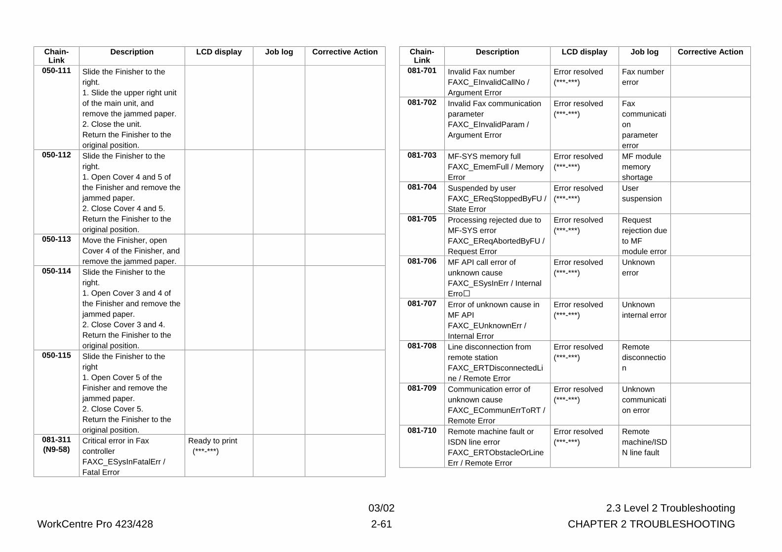
03/02 2.3 Level 2 Troubleshooting
WorkCentre Pro 423/428 2-61 CHAPTER 2 TROUBLESHOOTING
Chain-Link
Description LCD display Job log Corrective Action
050-111 Slide the Finisher to theright.1. Slide the upper right unitof the main unit, andremove the jammed paper.2. Close the unit.Return the Finisher to theoriginal position.
050-112 Slide the Finisher to theright.1. Open Cover 4 and 5 ofthe Finisher and remove thejammed paper.2. Close Cover 4 and 5.Return the Finisher to theoriginal position.
050-113 Move the Finisher, openCover 4 of the Finisher, andremove the jammed paper.
050-114 Slide the Finisher to theright.1. Open Cover 3 and 4 ofthe Finisher and remove thejammed paper.2. Close Cover 3 and 4.Return the Finisher to theoriginal position.
050-115 Slide the Finisher to theright1. Open Cover 5 of theFinisher and remove thejammed paper.2. Close Cover 5.Return the Finisher to theoriginal position.
081-311(N9-58)
Critical error in FaxcontrollerFAXC_ESysInFatalErr /Fatal Error
Ready to print (***-***)
Chain-Link
Description LCD display Job log Corrective Action
081-701 Invalid Fax numberFAXC_EInvalidCallNo /Argument Error
Error resolved(***-***)
Fax numbererror
081-702 Invalid Fax communicationparameterFAXC_EInvalidParam /Argument Error
Error resolved(***-***)
Faxcommunicationparametererror
081-703 MF-SYS memory fullFAXC_EmemFull / MemoryError
Error resolved(***-***)
MF modulememoryshortage
081-704 Suspended by userFAXC_EReqStoppedByFU /State Error
Error resolved(***-***)
Usersuspension
081-705 Processing rejected due toMF-SYS errorFAXC_EReqAbortedByFU /Request Error
Error resolved(***-***)
Requestrejection dueto MFmodule error
081-706 MF API call error ofunknown causeFAXC_ESysInErr / InternalErro�
Error resolved(***-***)
Unknownerror
081-707 Error of unknown cause inMF APIFAXC_EUnknownErr /Internal Error
Error resolved(***-***)
Unknowninternal error
081-708 Line disconnection fromremote stationFAXC_ERTDisconnectedLine / Remote Error
Error resolved(***-***)
Remotedisconnection
081-709 Communication error ofunknown causeFAXC_ECommunErrToRT /Remote Error
Error resolved(***-***)
Unknowncommunication error
081-710 Remote machine fault orISDN line errorFAXC_ERTObstacleOrLineErr / Remote Error
Error resolved(***-***)
Remotemachine/ISDN line fault
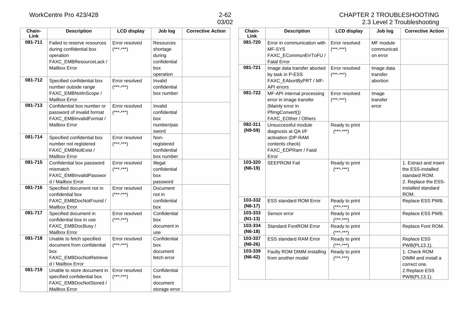
WorkCentre Pro 423/428 2-62 CHAPTER 2 TROUBLESHOOTING03/02 2.3 Level 2 Troubleshooting
Chain-Link
Description LCD display Job log Corrective Action
081-711 Failed to reserve resourcesduring confidential boxoperationFAXC_EMBResourceLack /Mailbox Error
Error resolved(***-***)
Resourcesshortageduringconfidentialboxoperation
081-712 Specified confidential boxnumber outside rangeFAXC_EMBNotInScope /Mailbox Error
Error resolved(***-***)
Invalidconfidentialbox number
081-713 Confidential box number orpassword of invalid formatFAXC_EMBInvalidFormat /Mailbox Error
Error resolved(***-***)
Invalidconfidentialboxnumber/password
081-714 Specified confidential boxnumber not registeredFAXC_EMBNotExist /Mailbox Error
Error resolved(***-***)
Non-registeredconfidentialbox number
081-715 Confidential box passwordmismatchFAXC_EMBInvalidPassword / Mailbox Error
Error resolved(***-***)
Illegalconfidentialboxpassword
081-716 Specified document not inconfidential boxFAXC_EMBDocNotFound /Mailbox Error
Error resolved(***-***)
Documentnot inconfidentialbox
081-717 Specified document inconfidential box in useFAXC_EMBDocBusy /Mailbox Error
Error resolved(***-***)
Confidentialboxdocument inuse
081-718 Unable to fetch specifieddocument from confidentialboxFAXC_EMBDocNotRetrieved / Mailbox Error
Error resolved(***-***)
Confidentialboxdocumentfetch error
081-719 Unable to store document inspecified confidential boxFAXC_EMBDocNotStored /Mailbox Error
Error resolved(***-***)
Confidentialboxdocumentstorage error
Chain-Link
Description LCD display Job log Corrective Action
081-720 Error in communication withMF-SYSFAXC_ECommunErrToFU /Fatal Error
Error resolved(***-***)
MF modulecommunication error
081-721 Image data transfer abortedby task in P-ESSFAXC_EAbortByPRT / MF-API errors
Error resolved(***-***)
Image datatransferabortion
081-722 MF-API internal processingerror in image transfer(Mainly error inPfimgConvert())FAXC_EOther / Others
Error resolved(***-***)
Imagetransfererror
082-311(N9-59)
Unsuccessful modulediagnosis at QA I/Factivation (DP-RAMcontents check)FAXC_EDPRam / FatalError
Ready to print (***-***)
103-320(N6-19)
SEEPROM Fail Ready to print (***-***)
1. Extract and insertthe ESS-installedstandard ROM.2. Replace the ESS-installed standardROM.
103-332(N6-17)
ESS standard ROM Error Ready to print (***-***)
Replace ESS PWB.
103-333(N1-13)
Sensor error Ready to print (***-***)
Replace ESS PWB.
103-334(N6-18)
Standard FontROM Error Ready to print (***-***)
Replace Font ROM.
103-337(N6-26)
ESS standard RAM Error Ready to print (***-***)
Replace ESSPWB(PL13.1).
103-339(N6-42)
Faulty ROM DIMM installingfrom another model
Ready to print (***-***)
1. Check ROMDIMM and install acorrect one.2.Replace ESSPWB(PL13.1).
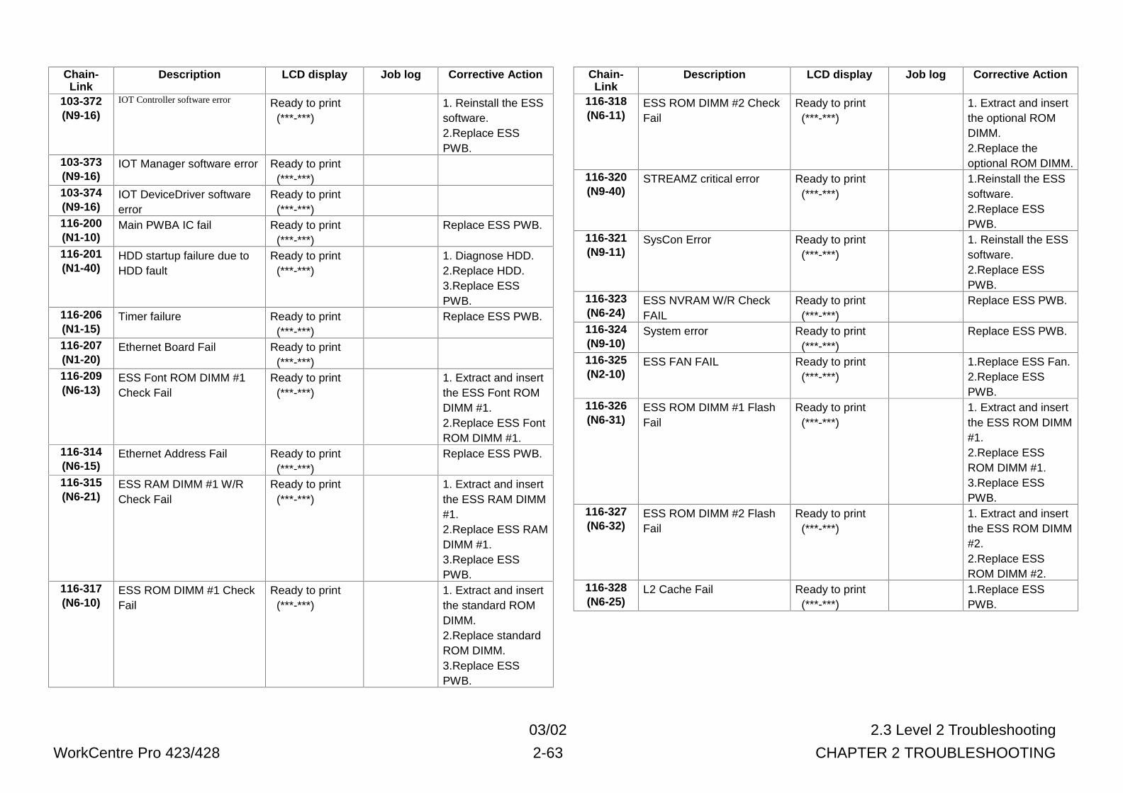
03/02 2.3 Level 2 Troubleshooting
WorkCentre Pro 423/428 2-63 CHAPTER 2 TROUBLESHOOTING
Chain-Link
Description LCD display Job log Corrective Action
103-372(N9-16)
IOT Controller software error Ready to print (***-***)
1. Reinstall the ESSsoftware.2.Replace ESSPWB.
103-373(N9-16)
IOT Manager software error Ready to print (***-***)
103-374(N9-16)
IOT DeviceDriver softwareerror
Ready to print (***-***)
116-200(N1-10)
Main PWBA IC fail Ready to print (***-***)
Replace ESS PWB.
116-201(N1-40)
HDD startup failure due toHDD fault
Ready to print (***-***)
1. Diagnose HDD.2.Replace HDD.3.Replace ESSPWB.
116-206(N1-15)
Timer failure Ready to print (***-***)
Replace ESS PWB.
116-207(N1-20)
Ethernet Board Fail Ready to print (***-***)
116-209(N6-13)
ESS Font ROM DIMM #1Check Fail
Ready to print (***-***)
1. Extract and insertthe ESS Font ROMDIMM #1.2.Replace ESS FontROM DIMM #1.
116-314(N6-15)
Ethernet Address Fail Ready to print (***-***)
Replace ESS PWB.
116-315(N6-21)
ESS RAM DIMM #1 W/RCheck Fail
Ready to print (***-***)
1. Extract and insertthe ESS RAM DIMM#1.2.Replace ESS RAMDIMM #1.3.Replace ESSPWB.
116-317(N6-10)
ESS ROM DIMM #1 CheckFail
Ready to print (***-***)
1. Extract and insertthe standard ROMDIMM.2.Replace standardROM DIMM.3.Replace ESSPWB.
Chain-Link
Description LCD display Job log Corrective Action
116-318(N6-11)
ESS ROM DIMM #2 CheckFail
Ready to print (***-***)
1. Extract and insertthe optional ROMDIMM.2.Replace theoptional ROM DIMM.
116-320(N9-40)
STREAMZ critical error Ready to print (***-***)
1.Reinstall the ESSsoftware.2.Replace ESSPWB.
116-321(N9-11)
SysCon Error Ready to print (***-***)
1. Reinstall the ESSsoftware.2.Replace ESSPWB.
116-323(N6-24)
ESS NVRAM W/R CheckFAIL
Ready to print (***-***)
Replace ESS PWB.
116-324(N9-10)
System error Ready to print (***-***)
Replace ESS PWB.
116-325(N2-10)
ESS FAN FAIL Ready to print (***-***)
1.Replace ESS Fan.2.Replace ESSPWB.
116-326(N6-31)
ESS ROM DIMM #1 FlashFail
Ready to print (***-***)
1. Extract and insertthe ESS ROM DIMM#1.2.Replace ESSROM DIMM #1.3.Replace ESSPWB.
116-327(N6-32)
ESS ROM DIMM #2 FlashFail
Ready to print (***-***)
1. Extract and insertthe ESS ROM DIMM#2.2.Replace ESSROM DIMM #2.
116-328(N6-25)
L2 Cache Fail Ready to print (***-***)
1.Replace ESSPWB.
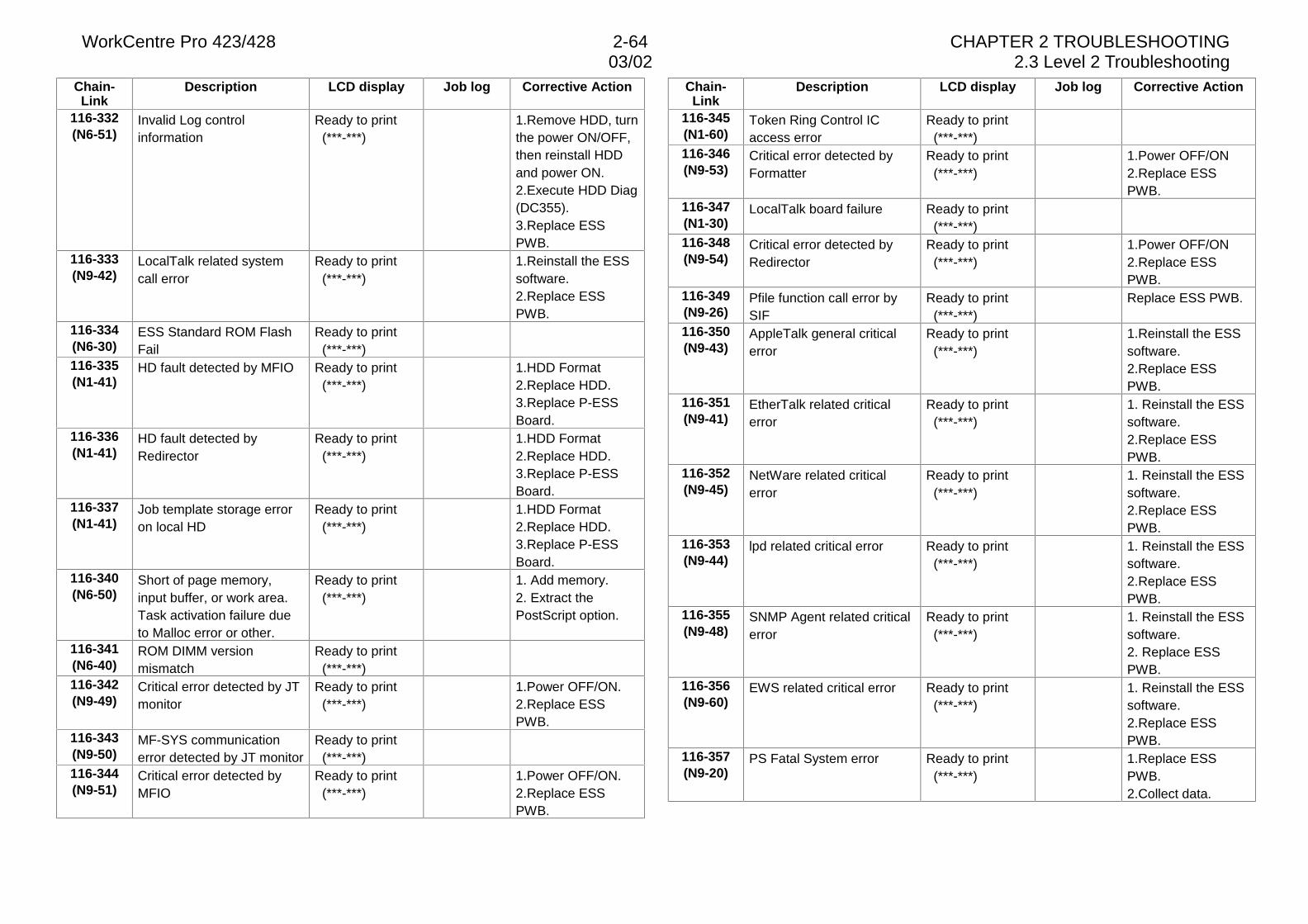
WorkCentre Pro 423/428 2-64 CHAPTER 2 TROUBLESHOOTING03/02 2.3 Level 2 Troubleshooting
Chain-Link
Description LCD display Job log Corrective Action
116-332(N6-51)
Invalid Log controlinformation
Ready to print (***-***)
1.Remove HDD, turnthe power ON/OFF,then reinstall HDDand power ON.2.Execute HDD Diag(DC355).3.Replace ESSPWB.
116-333(N9-42)
LocalTalk related systemcall error
Ready to print (***-***)
1.Reinstall the ESSsoftware.2.Replace ESSPWB.
116-334(N6-30)
ESS Standard ROM FlashFail
Ready to print (***-***)
116-335(N1-41)
HD fault detected by MFIO Ready to print (***-***)
1.HDD Format2.Replace HDD.3.Replace P-ESSBoard.
116-336(N1-41)
HD fault detected byRedirector
Ready to print (***-***)
1.HDD Format2.Replace HDD.3.Replace P-ESSBoard.
116-337(N1-41)
Job template storage erroron local HD
Ready to print (***-***)
1.HDD Format2.Replace HDD.3.Replace P-ESSBoard.
116-340(N6-50)
Short of page memory,input buffer, or work area.Task activation failure dueto Malloc error or other.
Ready to print (***-***)
1. Add memory.2. Extract thePostScript option.
116-341(N6-40)
ROM DIMM versionmismatch
Ready to print (***-***)
116-342(N9-49)
Critical error detected by JTmonitor
Ready to print (***-***)
1.Power OFF/ON.2.Replace ESSPWB.
116-343(N9-50)
MF-SYS communicationerror detected by JT monitor
Ready to print (***-***)
116-344(N9-51)
Critical error detected byMFIO
Ready to print (***-***)
1.Power OFF/ON.2.Replace ESSPWB.
Chain-Link
Description LCD display Job log Corrective Action
116-345(N1-60)
Token Ring Control ICaccess error
Ready to print (***-***)
116-346(N9-53)
Critical error detected byFormatter
Ready to print (***-***)
1.Power OFF/ON2.Replace ESSPWB.
116-347(N1-30)
LocalTalk board failure Ready to print (***-***)
116-348(N9-54)
Critical error detected byRedirector
Ready to print (***-***)
1.Power OFF/ON2.Replace ESSPWB.
116-349(N9-26)
Pfile function call error bySIF
Ready to print (***-***)
Replace ESS PWB.
116-350(N9-43)
AppleTalk general criticalerror
Ready to print (***-***)
1.Reinstall the ESSsoftware.2.Replace ESSPWB.
116-351(N9-41)
EtherTalk related criticalerror
Ready to print (***-***)
1. Reinstall the ESSsoftware.2.Replace ESSPWB.
116-352(N9-45)
NetWare related criticalerror
Ready to print (***-***)
1. Reinstall the ESSsoftware.2.Replace ESSPWB.
116-353(N9-44)
lpd related critical error Ready to print (***-***)
1. Reinstall the ESSsoftware.2.Replace ESSPWB.
116-355(N9-48)
SNMP Agent related criticalerror
Ready to print (***-***)
1. Reinstall the ESSsoftware.2. Replace ESSPWB.
116-356(N9-60)
EWS related critical error Ready to print (***-***)
1. Reinstall the ESSsoftware.2.Replace ESSPWB.
116-357(N9-20)
PS Fatal System error Ready to print (***-***)
1.Replace ESSPWB.2.Collect data.
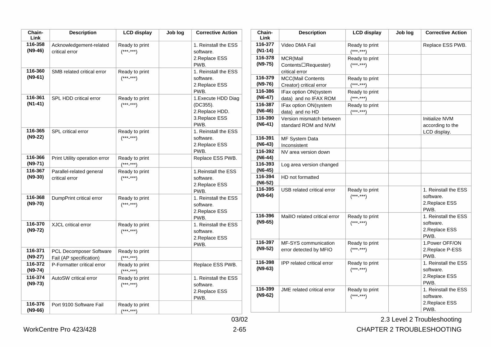
03/02 2.3 Level 2 Troubleshooting
WorkCentre Pro 423/428 2-65 CHAPTER 2 TROUBLESHOOTING
Chain-Link
Description LCD display Job log Corrective Action
116-358(N9-46)
Acknowledgement-relatedcritical error
Ready to print (***-***)
1. Reinstall the ESSsoftware.2.Replace ESSPWB.
116-360(N9-61)
SMB related critical error Ready to print (***-***)
1. Reinstall the ESSsoftware.2.Replace ESSPWB.
116-361(N1-41)
SPL HDD critical error Ready to print (***-***)
1.Execute HDD Diag(DC355).2.Replace HDD.3.Replace ESSPWB.
116-365(N9-22)
SPL critical error Ready to print (***-***)
1. Reinstall the ESSsoftware.2.Replace ESSPWB.
116-366(N9-71)
Print Utility operation error Ready to print (***-***)
Replace ESS PWB.
116-367(N9-30)
Parallel-related generalcritical error
Ready to print (***-***)
1.Reinstall the ESSsoftware.2.Replace ESSPWB.
116-368(N9-70)
DumpPrint critical error Ready to print (***-***)
1. Reinstall the ESSsoftware.2.Replace ESSPWB.
116-370(N9-72)
XJCL critical error Ready to print (***-***)
1. Reinstall the ESSsoftware.2.Replace ESSPWB.
116-371(N9-27)
PCL Decomposer SoftwareFail (AP specification)
Ready to print (***-***)
116-372(N9-74)
P-Formatter critical error Ready to print (***-***)
Replace ESS PWB.
116-374(N9-73)
AutoSW critical error Ready to print (***-***)
1. Reinstall the ESSsoftware.2.Replace ESSPWB.
116-376(N9-66)
Port 9100 Software Fail Ready to print (***-***)
Chain-Link
Description LCD display Job log Corrective Action
116-377(N1-14)
Video DMA Fail Ready to print (***-***)
Replace ESS PWB.
116-378(N9-75)
MCR(MailContents�Requester)critical error
Ready to print (***-***)
116-379(N9-76)
MCC(Mail ContentsCreator) critical error
Ready to print (***-***)
116-386(N6-47)
IFax option ON(systemdata) and no IFAX ROM
Ready to print (***-***)
116-387(N6-46)
IFax option ON(systemdata) and no HD
Ready to print (***-***)
116-390(N6-41)
Version mismatch betweenstandard ROM and NVM
Initialize NVMaccording to theLCD display.
116-391(N6-43)
MF System DataInconsistent
116-392(N6-44)
NV area version down
116-393(N6-45)
Log area version changed
116-394(N6-52)
HD not formatted
116-395(N9-64)
USB related critical error Ready to print (***-***)
1. Reinstall the ESSsoftware.2.Replace ESSPWB.
116-396(N9-65)
MailIO related critical error Ready to print (***-***)
1. Reinstall the ESSsoftware.2.Replace ESSPWB.
116-397(N9-52)
MF-SYS communicationerror detected by MFIO
Ready to print (***-***)
1.Power OFF/ON2.Replace P-ESSPWB.
116-398(N9-63)
IPP related critical error Ready to print (***-***)
1. Reinstall the ESSsoftware.2.Replace ESSPWB.
116-399(N9-62)
JME related critical error Ready to print (***-***)
1. Reinstall the ESSsoftware.2.Replace ESSPWB.
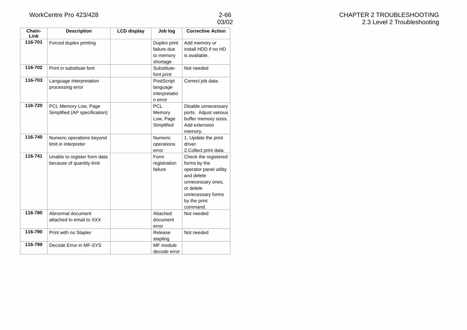
WorkCentre Pro 423/428 2-66 CHAPTER 2 TROUBLESHOOTING03/02 2.3 Level 2 Troubleshooting
Chain-Link
Description LCD display Job log Corrective Action
116-701 Forced duplex printing Duplex printfailure dueto memoryshortage
Add memory orinstall HDD if no HDis available.
116-702 Print in substitute font Substitute-font print
Not needed
116-703 Language interpretationprocessing error
PostScriptlanguageinterpretation error
Correct job data.
116-720 PCL Memory Low, PageSimplified (AP specification)
PCLMemoryLow, PageSimplified
Disable unnecessaryports. Adjust variousbuffer memory sizes.Add extensionmemory.
116-740 Numeric operations beyondlimit in interpreter
Numericoperationserror
1. Update the printdriver.2.Collect print data.
116-741 Unable to register form databecause of quantity limit
Formregistrationfailure
Check the registeredforms by theoperator panel utilityand deleteunnecessary ones,or deleteunnecessary formsby the printcommand.
116-780 Abnormal documentattached to email to XXX
Attacheddocumenterror
Not needed
116-790 Print with no Stapler Releasestapling
Not needed
116-799 Decode Error in MF-SYS MF moduledecode error
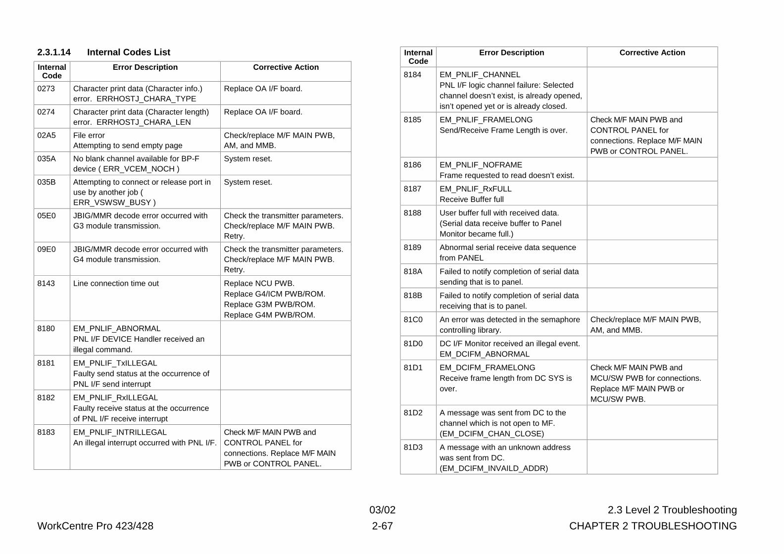
03/02 2.3 Level 2 Troubleshooting
WorkCentre Pro 423/428 2-67 CHAPTER 2 TROUBLESHOOTING
2.3.1.14 Internal Codes List
InternalCode
Error Description Corrective Action
0273 Character print data (Character info.)error. ERRHOSTJ_CHARA_TYPE
Replace OA I/F board.
0274 Character print data (Character length)error. ERRHOSTJ_CHARA_LEN
Replace OA I/F board.
02A5 File errorAttempting to send empty page
Check/replace M/F MAIN PWB,AM, and MMB.
035A No blank channel available for BP-Fdevice ( ERR_VCEM_NOCH )
System reset.
035B Attempting to connect or release port inuse by another job (ERR_VSWSW_BUSY )
System reset.
05E0 JBIG/MMR decode error occurred withG3 module transmission.
Check the transmitter parameters.Check/replace M/F MAIN PWB.Retry.
09E0 JBIG/MMR decode error occurred withG4 module transmission.
Check the transmitter parameters.Check/replace M/F MAIN PWB.Retry.
8143 Line connection time out Replace NCU PWB.Replace G4/ICM PWB/ROM.Replace G3M PWB/ROM.Replace G4M PWB/ROM.
8180 EM_PNLIF_ABNORMALPNL I/F DEVICE Handler received anillegal command.
8181 EM_PNLIF_TxILLEGALFaulty send status at the occurrence ofPNL I/F send interrupt
8182 EM_PNLIF_RxILLEGALFaulty receive status at the occurrenceof PNL I/F receive interrupt
8183 EM_PNLIF_INTRILLEGALAn illegal interrupt occurred with PNL I/F.
Check M/F MAIN PWB andCONTROL PANEL forconnections. Replace M/F MAINPWB or CONTROL PANEL.
InternalCode
Error Description Corrective Action
8184 EM_PNLIF_CHANNELPNL I/F logic channel failure: Selectedchannel doesn’t exist, is already opened,isn’t opened yet or is already closed.
8185 EM_PNLIF_FRAMELONGSend/Receive Frame Length is over.
Check M/F MAIN PWB andCONTROL PANEL forconnections. Replace M/F MAINPWB or CONTROL PANEL.
8186 EM_PNLIF_NOFRAMEFrame requested to read doesn’t exist.
8187 EM_PNLIF_RxFULLReceive Buffer full
8188 User buffer full with received data.(Serial data receive buffer to PanelMonitor became full.)
8189 Abnormal serial receive data sequencefrom PANEL
818A Failed to notify completion of serial datasending that is to panel.
818B Failed to notify completion of serial datareceiving that is to panel.
81C0 An error was detected in the semaphorecontrolling library.
Check/replace M/F MAIN PWB,AM, and MMB.
81D0 DC I/F Monitor received an illegal event.EM_DCIFM_ABNORMAL
81D1 EM_DCIFM_FRAMELONGReceive frame length from DC SYS isover.
Check M/F MAIN PWB andMCU/SW PWB for connections.Replace M/F MAIN PWB orMCU/SW PWB.
81D2 A message was sent from DC to thechannel which is not open to MF.(EM_DCIFM_CHAN_CLOSE)
81D3 A message with an unknown addresswas sent from DC.(EM_DCIFM_INVAILD_ADDR)
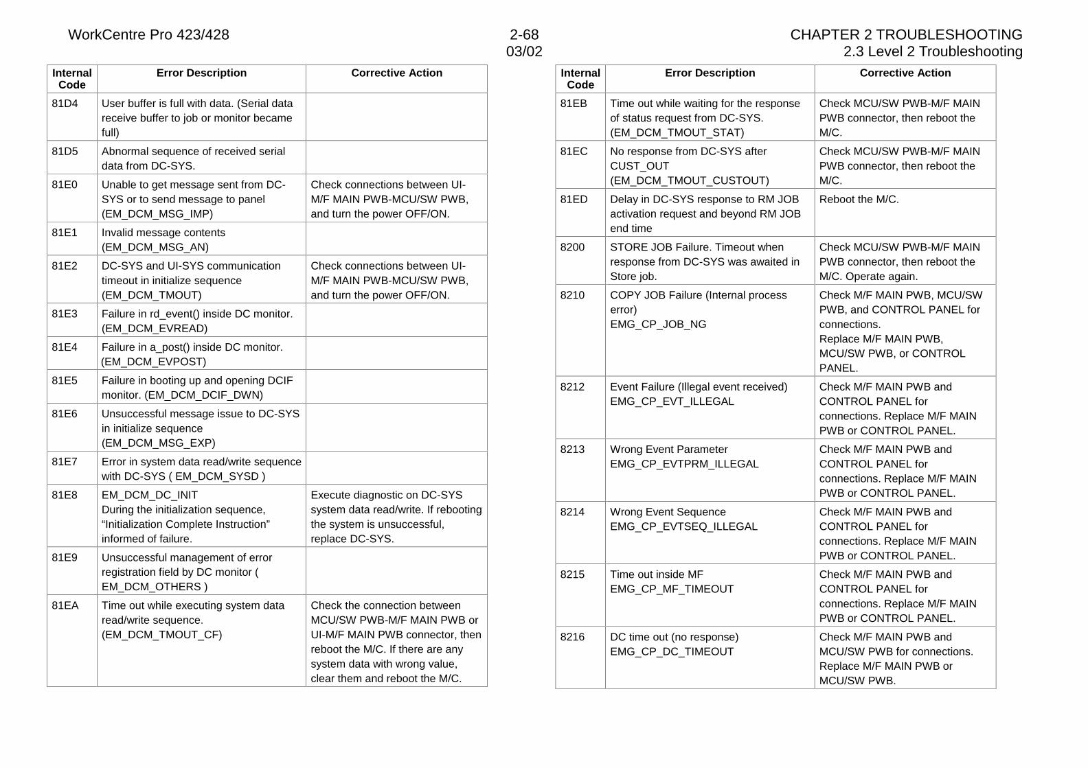
WorkCentre Pro 423/428 2-68 CHAPTER 2 TROUBLESHOOTING03/02 2.3 Level 2 Troubleshooting
InternalCode
Error Description Corrective Action
81D4 User buffer is full with data. (Serial datareceive buffer to job or monitor becamefull)
81D5 Abnormal sequence of received serialdata from DC-SYS.
81E0 Unable to get message sent from DC-SYS or to send message to panel(EM_DCM_MSG_IMP)
Check connections between UI-M/F MAIN PWB-MCU/SW PWB,and turn the power OFF/ON.
81E1 Invalid message contents(EM_DCM_MSG_AN)
81E2 DC-SYS and UI-SYS communicationtimeout in initialize sequence(EM_DCM_TMOUT)
Check connections between UI-M/F MAIN PWB-MCU/SW PWB,and turn the power OFF/ON.
81E3 Failure in rd_event() inside DC monitor.(EM_DCM_EVREAD)
81E4 Failure in a_post() inside DC monitor.(EM_DCM_EVPOST)
81E5 Failure in booting up and opening DCIFmonitor. (EM_DCM_DCIF_DWN)
81E6 Unsuccessful message issue to DC-SYSin initialize sequence(EM_DCM_MSG_EXP)
81E7 Error in system data read/write sequencewith DC-SYS ( EM_DCM_SYSD )
81E8 EM_DCM_DC_INITDuring the initialization sequence,“Initialization Complete Instruction”informed of failure.
Execute diagnostic on DC-SYSsystem data read/write. If rebootingthe system is unsuccessful,replace DC-SYS.
81E9 Unsuccessful management of errorregistration field by DC monitor (EM_DCM_OTHERS )
81EA Time out while executing system dataread/write sequence.(EM_DCM_TMOUT_CF)
Check the connection betweenMCU/SW PWB-M/F MAIN PWB orUI-M/F MAIN PWB connector, thenreboot the M/C. If there are anysystem data with wrong value,clear them and reboot the M/C.
InternalCode
Error Description Corrective Action
81EB Time out while waiting for the responseof status request from DC-SYS.(EM_DCM_TMOUT_STAT)
Check MCU/SW PWB-M/F MAINPWB connector, then reboot theM/C.
81EC No response from DC-SYS afterCUST_OUT(EM_DCM_TMOUT_CUSTOUT)
Check MCU/SW PWB-M/F MAINPWB connector, then reboot theM/C.
81ED Delay in DC-SYS response to RM JOBactivation request and beyond RM JOBend time
Reboot the M/C.
8200 STORE JOB Failure. Timeout whenresponse from DC-SYS was awaited inStore job.
Check MCU/SW PWB-M/F MAINPWB connector, then reboot theM/C. Operate again.
8210 COPY JOB Failure (Internal processerror)EMG_CP_JOB_NG
Check M/F MAIN PWB, MCU/SWPWB, and CONTROL PANEL forconnections.Replace M/F MAIN PWB,MCU/SW PWB, or CONTROLPANEL.
8212 Event Failure (Illegal event received)EMG_CP_EVT_ILLEGAL
Check M/F MAIN PWB andCONTROL PANEL forconnections. Replace M/F MAINPWB or CONTROL PANEL.
8213 Wrong Event ParameterEMG_CP_EVTPRM_ILLEGAL
Check M/F MAIN PWB andCONTROL PANEL forconnections. Replace M/F MAINPWB or CONTROL PANEL.
8214 Wrong Event SequenceEMG_CP_EVTSEQ_ILLEGAL
Check M/F MAIN PWB andCONTROL PANEL forconnections. Replace M/F MAINPWB or CONTROL PANEL.
8215 Time out inside MFEMG_CP_MF_TIMEOUT
Check M/F MAIN PWB andCONTROL PANEL forconnections. Replace M/F MAINPWB or CONTROL PANEL.
8216 DC time out (no response)EMG_CP_DC_TIMEOUT
Check M/F MAIN PWB andMCU/SW PWB for connections.Replace M/F MAIN PWB orMCU/SW PWB.
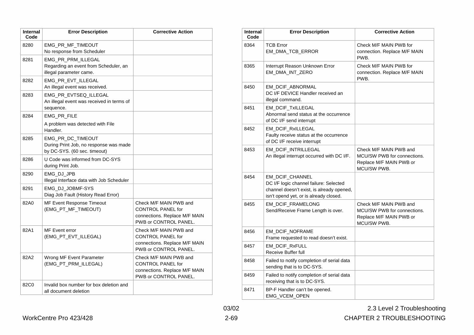
03/02 2.3 Level 2 Troubleshooting
WorkCentre Pro 423/428 2-69 CHAPTER 2 TROUBLESHOOTING
InternalCode
Error Description Corrective Action
8280 EMG_PR_MF_TIMEOUTNo response from Scheduler
8281 EMG_PR_PRM_ILLEGALRegarding an event from Scheduler, anillegal parameter came.
8282 EMG_PR_EVT_ILLEGALAn illegal event was received.
8283 EMG_PR_EVTSEQ_ILLEGALAn illegal event was received in terms ofsequence.
8284 EMG_PR_FILE
A problem was detected with FileHandler.
8285 EMG_PR_DC_TIMEOUTDuring Print Job, no response was madeby DC-SYS. (60 sec. timeout)
8286 U Code was informed from DC-SYSduring Print Job.
8290 EMG_DJ_JPBIllegal Interface data with Job Scheduler
8291 EMG_DJ_JOBMF-SYSDiag Job Fault (History Read Error)
82A0 MF Event Response Timeout(EMG_PT_MF_TIMEOUT)
Check M/F MAIN PWB andCONTROL PANEL forconnections. Replace M/F MAINPWB or CONTROL PANEL.
82A1 MF Event error(EMG_PT_EVT_ILLEGAL)
Check M/F MAIN PWB andCONTROL PANEL forconnections. Replace M/F MAINPWB or CONTROL PANEL.
82A2 Wrong MF Event Parameter(EMG_PT_PRM_ILLEGAL)
Check M/F MAIN PWB andCONTROL PANEL forconnections. Replace M/F MAINPWB or CONTROL PANEL.
82C0 Invalid box number for box deletion andall document deletion
InternalCode
Error Description Corrective Action
8364 TCB ErrorEM_DMA_TCB_ERROR
Check M/F MAIN PWB forconnection. Replace M/F MAINPWB.
8365 Interrupt Reason Unknown ErrorEM_DMA_INT_ZERO
Check M/F MAIN PWB forconnection. Replace M/F MAINPWB.
8450 EM_DCIF_ABNORMALDC I/F DEVICE Handler received anillegal command.
8451 EM_DCIF_TxILLEGALAbnormal send status at the occurrenceof DC I/F send interrupt
8452 EM_DCIF_RxILLEGALFaulty receive status at the occurrenceof DC I/F receive interrupt
8453 EM_DCIF_INTRILLEGALAn illegal interrupt occurred with DC I/F.
Check M/F MAIN PWB andMCU/SW PWB for connections.Replace M/F MAIN PWB orMCU/SW PWB.
8454 EM_DCIF_CHANNELDC I/F logic channel failure: Selectedchannel doesn’t exist, is already opened,isn’t opend yet, or is already closed.
8455 EM_DCIF_FRAMELONGSend/Receive Frame Length is over.
Check M/F MAIN PWB andMCU/SW PWB for connections.Replace M/F MAIN PWB orMCU/SW PWB.
8456 EM_DCIF_NOFRAMEFrame requested to read doesn’t exist.
8457 EM_DCIF_RxFULLReceive Buffer full
8458 Failed to notify completion of serial datasending that is to DC-SYS.
8459 Failed to notify completion of serial datareceiving that is to DC-SYS.
8471 BP-F Handler can’t be opened.EMG_VCEM_OPEN
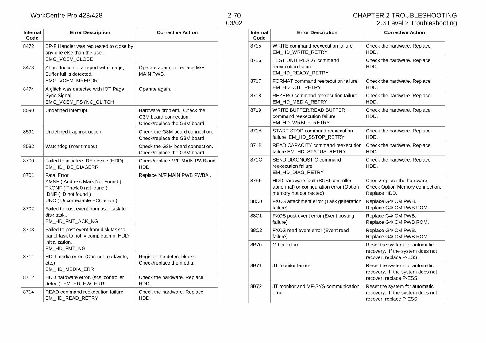
WorkCentre Pro 423/428 2-70 CHAPTER 2 TROUBLESHOOTING03/02 2.3 Level 2 Troubleshooting
InternalCode
Error Description Corrective Action
8472 BP-F Handler was requested to close byany one else than the user.EMG_VCEM_CLOSE
8473 At production of a report with image,Buffer full is detected.EMG_VCEM_MREPORT
Operate again, or replace M/FMAIN PWB.
8474 A glitch was detected with IOT PageSync Signal.EMG_VCEM_PSYNC_GLITCH
Operate again.
8590 Undefined interrupt Hardware problem. Check theG3M board connection.Check/replace the G3M board.
8591 Undefined trap instruction Check the G3M board connection.Check/replace the G3M board.
8592 Watchdog timer timeout Check the G3M board connection.Check/replace the G3M board.
8700 Failed to initialize IDE device (HDD) .EM_HD_IDE_DIAGERR
Check/replace M/F MAIN PWB andHDD.
8701 Fatal ErrorAMNF ( Address Mark Not Found )TKONF ( Track 0 not found )IDNF ( ID not found )UNC ( Uncorrectable ECC error )
Replace M/F MAIN PWB PWBA .
8702 Failed to post event from user task todisk task..EM_HD_FMT_ACK_NG
8703 Failed to post event from disk task topanel task to notify completion of HDDinitialization.EM_HD_FMT_NG
8711 HDD media error. (Can not read/write,etc.)EM_HD_MEDIA_ERR
Register the defect blocks.Check/replace the media.
8712 HDD hardware error. (scsi controllerdefect) EM_HD_HW_ERR
Check the hardware. ReplaceHDD.
8714 READ command reexecution failureEM_HD_READ_RETRY
Check the hardware. ReplaceHDD.
InternalCode
Error Description Corrective Action
8715 WRITE command reexecution failureEM_HD_WRITE_RETRY
Check the hardware. ReplaceHDD.
8716 TEST UNIT READY commandreexecution failureEM_HD_READY_RETRY
Check the hardware. ReplaceHDD.
8717 FORMAT command reexecution failureEM_HD_CTL_RETRY
Check the hardware. ReplaceHDD.
8718 REZERO command reexecution failureEM_HD_MEDIA_RETRY
Check the hardware. ReplaceHDD.
8719 WRITE BUFFER/READ BUFFERcommand reexecution failureEM_HD_WRBUF_RETRY
Check the hardware. ReplaceHDD.
871A START STOP command reexecutionfailure EM_HD_SSTOP_RETRY
Check the hardware. ReplaceHDD.
871B READ CAPACITY command reexecutionfailure EM_HD_STATUS_RETRY
Check the hardware. ReplaceHDD.
871C SEND DIAGNOSTIC commandreexecution failureEM_HD_DIAG_RETRY
Check the hardware. ReplaceHDD.
87FF HDD hardware fault (SCSI controllerabnormal) or configuration error (Optionmemory not connected)
Check/replace the hardware.Check Option Memory connection.Replace HDD.
88C0 FXOS attachment error (Task generationfailure)
Replace G4/ICM PWB.Replace G4/ICM PWB ROM.
88C1 FXOS post event error (Event postingfailure)
Replace G4/ICM PWB.Replace G4/ICM PWB ROM.
88C2 FXOS read event error (Event readfailure)
Replace G4/ICM PWB.Replace G4/ICM PWB ROM.
8B70 Other failure Reset the system for automaticrecovery. If the system does notrecover, replace P-ESS.
8B71 JT monitor failure Reset the system for automaticrecovery. If the system does notrecover, replace P-ESS.
8B72 JT monitor and MF-SYS communicationerror
Reset the system for automaticrecovery. If the system does notrecover, replace P-ESS.
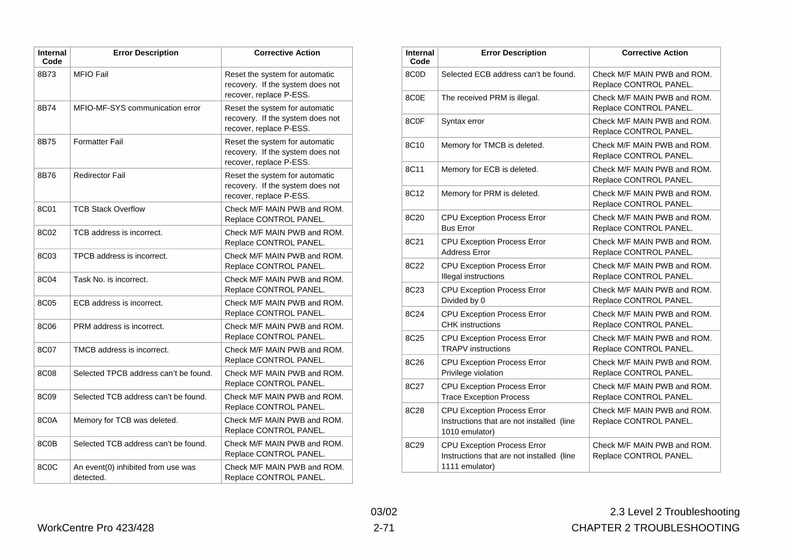
03/02 2.3 Level 2 Troubleshooting
WorkCentre Pro 423/428 2-71 CHAPTER 2 TROUBLESHOOTING
InternalCode
Error Description Corrective Action
8B73 MFIO Fail Reset the system for automaticrecovery. If the system does notrecover, replace P-ESS.
8B74 MFIO-MF-SYS communication error Reset the system for automaticrecovery. If the system does notrecover, replace P-ESS.
8B75 Formatter Fail Reset the system for automaticrecovery. If the system does notrecover, replace P-ESS.
8B76 Redirector Fail Reset the system for automaticrecovery. If the system does notrecover, replace P-ESS.
8C01 TCB Stack Overflow Check M/F MAIN PWB and ROM.Replace CONTROL PANEL.
8C02 TCB address is incorrect. Check M/F MAIN PWB and ROM.Replace CONTROL PANEL.
8C03 TPCB address is incorrect. Check M/F MAIN PWB and ROM.Replace CONTROL PANEL.
8C04 Task No. is incorrect. Check M/F MAIN PWB and ROM.Replace CONTROL PANEL.
8C05 ECB address is incorrect. Check M/F MAIN PWB and ROM.Replace CONTROL PANEL.
8C06 PRM address is incorrect. Check M/F MAIN PWB and ROM.Replace CONTROL PANEL.
8C07 TMCB address is incorrect. Check M/F MAIN PWB and ROM.Replace CONTROL PANEL.
8C08 Selected TPCB address can’t be found. Check M/F MAIN PWB and ROM.Replace CONTROL PANEL.
8C09 Selected TCB address can’t be found. Check M/F MAIN PWB and ROM.Replace CONTROL PANEL.
8C0A Memory for TCB was deleted. Check M/F MAIN PWB and ROM.Replace CONTROL PANEL.
8C0B Selected TCB address can’t be found. Check M/F MAIN PWB and ROM.Replace CONTROL PANEL.
8C0C An event(0) inhibited from use wasdetected.
Check M/F MAIN PWB and ROM.Replace CONTROL PANEL.
InternalCode
Error Description Corrective Action
8C0D Selected ECB address can’t be found. Check M/F MAIN PWB and ROM.Replace CONTROL PANEL.
8C0E The received PRM is illegal. Check M/F MAIN PWB and ROM.Replace CONTROL PANEL.
8C0F Syntax error Check M/F MAIN PWB and ROM.Replace CONTROL PANEL.
8C10 Memory for TMCB is deleted. Check M/F MAIN PWB and ROM.Replace CONTROL PANEL.
8C11 Memory for ECB is deleted. Check M/F MAIN PWB and ROM.Replace CONTROL PANEL.
8C12 Memory for PRM is deleted. Check M/F MAIN PWB and ROM.Replace CONTROL PANEL.
8C20 CPU Exception Process ErrorBus Error
Check M/F MAIN PWB and ROM.Replace CONTROL PANEL.
8C21 CPU Exception Process ErrorAddress Error
Check M/F MAIN PWB and ROM.Replace CONTROL PANEL.
8C22 CPU Exception Process ErrorIllegal instructions
Check M/F MAIN PWB and ROM.Replace CONTROL PANEL.
8C23 CPU Exception Process ErrorDivided by 0
Check M/F MAIN PWB and ROM.Replace CONTROL PANEL.
8C24 CPU Exception Process ErrorCHK instructions
Check M/F MAIN PWB and ROM.Replace CONTROL PANEL.
8C25 CPU Exception Process ErrorTRAPV instructions
Check M/F MAIN PWB and ROM.Replace CONTROL PANEL.
8C26 CPU Exception Process ErrorPrivilege violation
Check M/F MAIN PWB and ROM.Replace CONTROL PANEL.
8C27 CPU Exception Process ErrorTrace Exception Process
Check M/F MAIN PWB and ROM.Replace CONTROL PANEL.
8C28 CPU Exception Process ErrorInstructions that are not installed (line1010 emulator)
Check M/F MAIN PWB and ROM.Replace CONTROL PANEL.
8C29 CPU Exception Process ErrorInstructions that are not installed (line1111 emulator)
Check M/F MAIN PWB and ROM.Replace CONTROL PANEL.
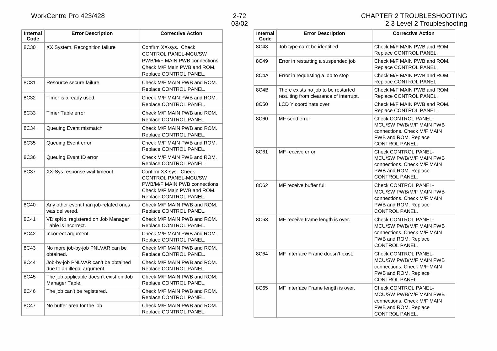
WorkCentre Pro 423/428 2-72 CHAPTER 2 TROUBLESHOOTING03/02 2.3 Level 2 Troubleshooting
InternalCode
Error Description Corrective Action
8C30 XX System, Recognition failure Confirm XX-sys. CheckCONTROL PANEL-MCU/SWPWB/M/F MAIN PWB connections.Check M/F Main PWB and ROM.Replace CONTROL PANEL.
8C31 Resource secure failure Check M/F MAIN PWB and ROM.Replace CONTROL PANEL.
8C32 Timer is already used. Check M/F MAIN PWB and ROM.Replace CONTROL PANEL.
8C33 Timer Table error Check M/F MAIN PWB and ROM.Replace CONTROL PANEL.
8C34 Queuing Event mismatch Check M/F MAIN PWB and ROM.Replace CONTROL PANEL.
8C35 Queuing Event error Check M/F MAIN PWB and ROM.Replace CONTROL PANEL.
8C36 Queuing Event ID error Check M/F MAIN PWB and ROM.Replace CONTROL PANEL.
8C37 XX-Sys response wait timeout Confirm XX-sys. CheckCONTROL PANEL-MCU/SWPWB/M/F MAIN PWB connections.Check M/F Main PWB and ROM.Replace CONTROL PANEL.
8C40 Any other event than job-related oneswas delivered.
Check M/F MAIN PWB and ROM.Replace CONTROL PANEL.
8C41 VDispNo. registered on Job ManagerTable is incorrect.
Check M/F MAIN PWB and ROM.Replace CONTROL PANEL.
8C42 Incorrect argument Check M/F MAIN PWB and ROM.Replace CONTROL PANEL.
8C43 No more job-by-job PNLVAR can beobtained.
Check M/F MAIN PWB and ROM.Replace CONTROL PANEL.
8C44 Job-by-job PNLVAR can’t be obtaineddue to an illegal argument.
Check M/F MAIN PWB and ROM.Replace CONTROL PANEL.
8C45 The job applicable doesn’t exist on JobManager Table.
Check M/F MAIN PWB and ROM.Replace CONTROL PANEL.
8C46 The job can’t be registered. Check M/F MAIN PWB and ROM.Replace CONTROL PANEL.
8C47 No buffer area for the job Check M/F MAIN PWB and ROM.Replace CONTROL PANEL.
InternalCode
Error Description Corrective Action
8C48 Job type can’t be identified. Check M/F MAIN PWB and ROM.Replace CONTROL PANEL.
8C49 Error in restarting a suspended job Check M/F MAIN PWB and ROM.Replace CONTROL PANEL.
8C4A Error in requesting a job to stop Check M/F MAIN PWB and ROM.Replace CONTROL PANEL.
8C4B There exists no job to be restartedresulting from clearance of interrupt.
Check M/F MAIN PWB and ROM.Replace CONTROL PANEL.
8C50 LCD Y coordinate over Check M/F MAIN PWB and ROM.Replace CONTROL PANEL.
8C60 MF send error Check CONTROL PANEL-MCU/SW PWB/M/F MAIN PWBconnections. Check M/F MAINPWB and ROM. ReplaceCONTROL PANEL.
8C61 MF receive error Check CONTROL PANEL-MCU/SW PWB/M/F MAIN PWBconnections. Check M/F MAINPWB and ROM. ReplaceCONTROL PANEL.
8C62 MF receive buffer full Check CONTROL PANEL-MCU/SW PWB/M/F MAIN PWBconnections. Check M/F MAINPWB and ROM. ReplaceCONTROL PANEL.
8C63 MF receive frame length is over. Check CONTROL PANEL-MCU/SW PWB/M/F MAIN PWBconnections. Check M/F MAINPWB and ROM. ReplaceCONTROL PANEL.
8C64 MF Interface Frame doesn’t exist. Check CONTROL PANEL-MCU/SW PWB/M/F MAIN PWBconnections. Check M/F MAINPWB and ROM. ReplaceCONTROL PANEL.
8C65 MF Interface Frame length is over. Check CONTROL PANEL-MCU/SW PWB/M/F MAIN PWBconnections. Check M/F MAINPWB and ROM. ReplaceCONTROL PANEL.
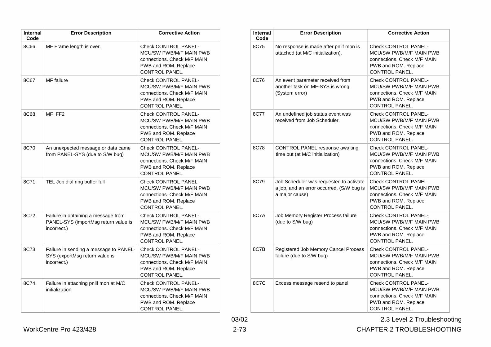
03/02 2.3 Level 2 Troubleshooting
WorkCentre Pro 423/428 2-73 CHAPTER 2 TROUBLESHOOTING
InternalCode
Error Description Corrective Action
8C66 MF Frame length is over. Check CONTROL PANEL-MCU/SW PWB/M/F MAIN PWBconnections. Check M/F MAINPWB and ROM. ReplaceCONTROL PANEL.
8C67 MF failure Check CONTROL PANEL-MCU/SW PWB/M/F MAIN PWBconnections. Check M/F MAINPWB and ROM. ReplaceCONTROL PANEL.
8C68 MF FF2 Check CONTROL PANEL-MCU/SW PWB/M/F MAIN PWBconnections. Check M/F MAINPWB and ROM. ReplaceCONTROL PANEL.
8C70 An unexpected message or data camefrom PANEL-SYS (due to S/W bug)
Check CONTROL PANEL-MCU/SW PWB/M/F MAIN PWBconnections. Check M/F MAINPWB and ROM. ReplaceCONTROL PANEL.
8C71 TEL Job dial ring buffer full Check CONTROL PANEL-MCU/SW PWB/M/F MAIN PWBconnections. Check M/F MAINPWB and ROM. ReplaceCONTROL PANEL.
8C72 Failure in obtaining a message fromPANEL-SYS (importMsg return value isincorrect.)
Check CONTROL PANEL-MCU/SW PWB/M/F MAIN PWBconnections. Check M/F MAINPWB and ROM. ReplaceCONTROL PANEL.
8C73 Failure in sending a message to PANEL-SYS (exportMsg return value isincorrect.)
Check CONTROL PANEL-MCU/SW PWB/M/F MAIN PWBconnections. Check M/F MAINPWB and ROM. ReplaceCONTROL PANEL.
8C74 Failure in attaching pnlif mon at M/Cinitialization
Check CONTROL PANEL-MCU/SW PWB/M/F MAIN PWBconnections. Check M/F MAINPWB and ROM. ReplaceCONTROL PANEL.
InternalCode
Error Description Corrective Action
8C75 No response is made after pnlif mon isattached (at M/C initialization).
Check CONTROL PANEL-MCU/SW PWB/M/F MAIN PWBconnections. Check M/F MAINPWB and ROM. ReplaceCONTROL PANEL.
8C76 An event parameter received fromanother task on MF-SYS is wrong.(System error)
Check CONTROL PANEL-MCU/SW PWB/M/F MAIN PWBconnections. Check M/F MAINPWB and ROM. ReplaceCONTROL PANEL.
8C77 An undefined job status event wasreceived from Job Scheduler.
Check CONTROL PANEL-MCU/SW PWB/M/F MAIN PWBconnections. Check M/F MAINPWB and ROM. ReplaceCONTROL PANEL.
8C78 CONTROL PANEL response awaitingtime out (at M/C initialization)
Check CONTROL PANEL-MCU/SW PWB/M/F MAIN PWBconnections. Check M/F MAINPWB and ROM. ReplaceCONTROL PANEL.
8C79 Job Scheduler was requested to activatea job, and an error occurred. (S/W bug isa major cause)
Check CONTROL PANEL-MCU/SW PWB/M/F MAIN PWBconnections. Check M/F MAINPWB and ROM. ReplaceCONTROL PANEL.
8C7A Job Memory Register Process failure(due to S/W bug)
Check CONTROL PANEL-MCU/SW PWB/M/F MAIN PWBconnections. Check M/F MAINPWB and ROM. ReplaceCONTROL PANEL.
8C7B Registered Job Memory Cancel Processfailure (due to S/W bug)
Check CONTROL PANEL-MCU/SW PWB/M/F MAIN PWBconnections. Check M/F MAINPWB and ROM. ReplaceCONTROL PANEL.
8C7C Excess message resend to panel Check CONTROL PANEL-MCU/SW PWB/M/F MAIN PWBconnections. Check M/F MAINPWB and ROM. ReplaceCONTROL PANEL.
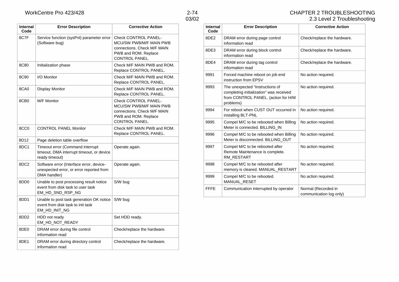
WorkCentre Pro 423/428 2-74 CHAPTER 2 TROUBLESHOOTING03/02 2.3 Level 2 Troubleshooting
InternalCode
Error Description Corrective Action
8C7F Service function (sysPnl) parameter error(Software bug)
Check CONTROL PANEL-MCU/SW PWB/M/F MAIN PWBconnections. Check M/F MAINPWB and ROM. ReplaceCONTROL PANEL.
8C80 Initialization phase Check M/F MAIN PWB and ROM.Replace CONTROL PANEL.
8C90 I/O Monitor Check M/F MAIN PWB and ROM.Replace CONTROL PANEL.
8CA0 Display Monitor Check M/F MAIN PWB and ROM.Replace CONTROL PANEL.
8CB0 M/F Monitor Check CONTROL PANEL-MCU/SW PWB/M/F MAIN PWBconnections. Check M/F MAINPWB and ROM. ReplaceCONTROL PANEL.
8CC0 CONTROL PANEL Monitor Check M/F MAIN PWB and ROM.Replace CONTROL PANEL.
8D12 Page deletion table overflow
8DC1 Timeout error (Command interrupttimeout, DMA interrupt timeout, or deviceready timeout)
Operate again.
8DC2 Software error (Interface error, device-unexpected error, or error reported fromDMA handler)
Operate again.
8DD0 Unable to post processing result noticeevent from disk task to user taskEM_HD_SND_RSP_NG
S/W bug
8DD1 Unable to post task generation OK noticeevent from disk task to init taskEM_HD_INIT_NG
S/W bug
8DD2 HDD not readyEM_HD_NOT_READY
Set HDD ready.
8DE0 DRAM error during file controlinformation read
Check/replace the hardware.
8DE1 DRAM error during directory controlinformation read
Check/replace the hardware.
InternalCode
Error Description Corrective Action
8DE2 DRAM error during page controlinformation read
Check/replace the hardware.
8DE3 DRAM error during block controlinformation read
Check/replace the hardware.
8DE4 DRAM error during tag controlinformation read
Check/replace the hardware.
9991 Forced machine reboot on job endinstruction from EPSV
No action required.
9993 The unexpected “Instructions ofcompleting initialization” was receivedfrom CONTROL PANEL. (action for H/Wproblems)
No action required.
9994 For reboot when CUST OUT occurred ininstalling BLT-PNL
No action required.
9995 Compel M/C to be rebooted when BillingMeter is connected. BILLING_IN
No action required.
9996 Compel M/C to be rebooted when BillingMeter is disconnected. BILLING_OUT
No action required.
9997 Compel M/C to be rebooted afterRemote Maintenance is complete.RM_RESTART
No action required.
9998 Compel M/C to be rebooted aftermemory is cleared. MANUAL_RESTART
No action required.
9999 Compel M/C to be rebooted.MANUAL_RESET
No action required.
FFFE Communication interrupted by operator Normal (Recorded incommunication log only)
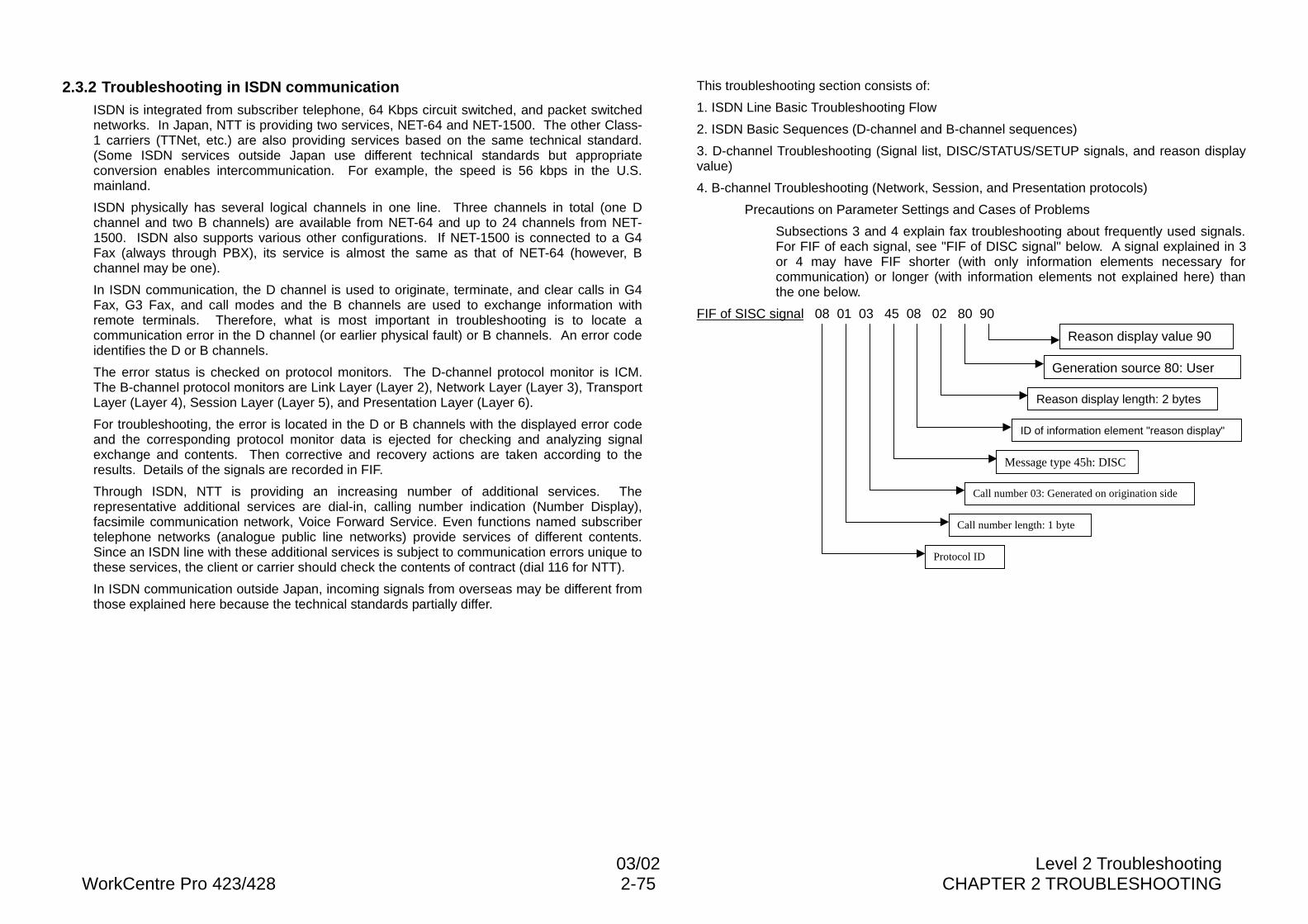
03/02 Level 2 TroubleshootingWorkCentre Pro 423/428 2-75 CHAPTER 2 TROUBLESHOOTING
2.3.2 Troubleshooting in ISDN communicationISDN is integrated from subscriber telephone, 64 Kbps circuit switched, and packet switchednetworks. In Japan, NTT is providing two services, NET-64 and NET-1500. The other Class-1 carriers (TTNet, etc.) are also providing services based on the same technical standard.(Some ISDN services outside Japan use different technical standards but appropriateconversion enables intercommunication. For example, the speed is 56 kbps in the U.S.mainland.
ISDN physically has several logical channels in one line. Three channels in total (one Dchannel and two B channels) are available from NET-64 and up to 24 channels from NET-1500. ISDN also supports various other configurations. If NET-1500 is connected to a G4Fax (always through PBX), its service is almost the same as that of NET-64 (however, Bchannel may be one).
In ISDN communication, the D channel is used to originate, terminate, and clear calls in G4Fax, G3 Fax, and call modes and the B channels are used to exchange information withremote terminals. Therefore, what is most important in troubleshooting is to locate acommunication error in the D channel (or earlier physical fault) or B channels. An error codeidentifies the D or B channels.
The error status is checked on protocol monitors. The D-channel protocol monitor is ICM.The B-channel protocol monitors are Link Layer (Layer 2), Network Layer (Layer 3), TransportLayer (Layer 4), Session Layer (Layer 5), and Presentation Layer (Layer 6).
For troubleshooting, the error is located in the D or B channels with the displayed error codeand the corresponding protocol monitor data is ejected for checking and analyzing signalexchange and contents. Then corrective and recovery actions are taken according to theresults. Details of the signals are recorded in FIF.
Through ISDN, NTT is providing an increasing number of additional services. Therepresentative additional services are dial-in, calling number indication (Number Display),facsimile communication network, Voice Forward Service. Even functions named subscribertelephone networks (analogue public line networks) provide services of different contents.Since an ISDN line with these additional services is subject to communication errors unique tothese services, the client or carrier should check the contents of contract (dial 116 for NTT).
In ISDN communication outside Japan, incoming signals from overseas may be different fromthose explained here because the technical standards partially differ.
This troubleshooting section consists of:
1. ISDN Line Basic Troubleshooting Flow
2. ISDN Basic Sequences (D-channel and B-channel sequences)
3. D-channel Troubleshooting (Signal list, DISC/STATUS/SETUP signals, and reason displayvalue)
4. B-channel Troubleshooting (Network, Session, and Presentation protocols)
Precautions on Parameter Settings and Cases of Problems
Subsections 3 and 4 explain fax troubleshooting about frequently used signals.For FIF of each signal, see "FIF of DISC signal" below. A signal explained in 3or 4 may have FIF shorter (with only information elements necessary forcommunication) or longer (with information elements not explained here) thanthe one below.
FIF of SISC signal 08 01 03 45 08 02 80 90
Reason display value 90
Generation source 80: User
Reason display length: 2 bytes
ID of information element "reason display"
Message type 45h: DISC
Call number 03: Generated on origination side
Call number length: 1 byte
Protocol ID
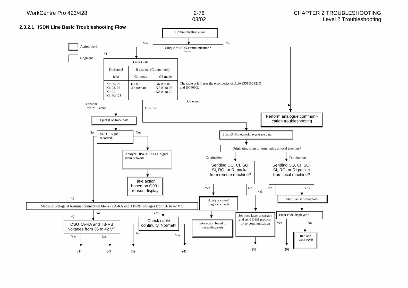
WorkCentre Pro 423/428 2-76 CHAPTER 2 TROUBLESHOOTING03/02 Level 2 Troubleshooting
2.3.2.1 ISDN Line Basic Troubleshooting Flow
Termination
*4
The table at left uses the error codes of Able 3351G/3321Gand DC400G.
G�HUURU
Origination
Originating from or terminating at local machine?
Eject G4M network layer trace data
G3 error
Perform analogue communi-cation troubleshooting
Yes
Take action based oncause/diagnosis
Analyze cause/diagnostic code
Yes
YesNo
No
ReplaceG4M PWB
Start Fax self-diagnosis
Set trace layer to sessionand send G4M protocolby re-communication
Judgment
Action/work
D channel� ,&0��HUURU
No
*1
Yes
Yes
Error Code
D channel B channel (Comm mode)
K0-00, 03K6-03, 07K9-01X3-60���
ICM
K7-07X3-00to40
G4 mode
K6-0 to 07K7-00 to 07X2-00 to 75
G3 mode
NoUnique to ISDN communication?
kaise
SETUP signalrecorded?
Eject ICM trace data
No
*2
Take actionbased on Q931reason display
Analyze DISC/STATUS signalfrom network
NoYes
Yes*2
Yes No
DSU TA-RA and TB-RBvoltages from 36 to 42 V?
Communication error
Sending CQ, CI, SQ,SI, RQ, or RI packet
from remote machine?
Measure voltage at terminal connection block (TA-RA and TB-RB voltages from 36 to 42 V?)
No
(1) (3) (4)(5)(2)
Error code displayed?
(6)
Sending CQ, CI, SQ,SI, RQ, or RI packetfrom local machine?
Check cablecontinuity. Normal?
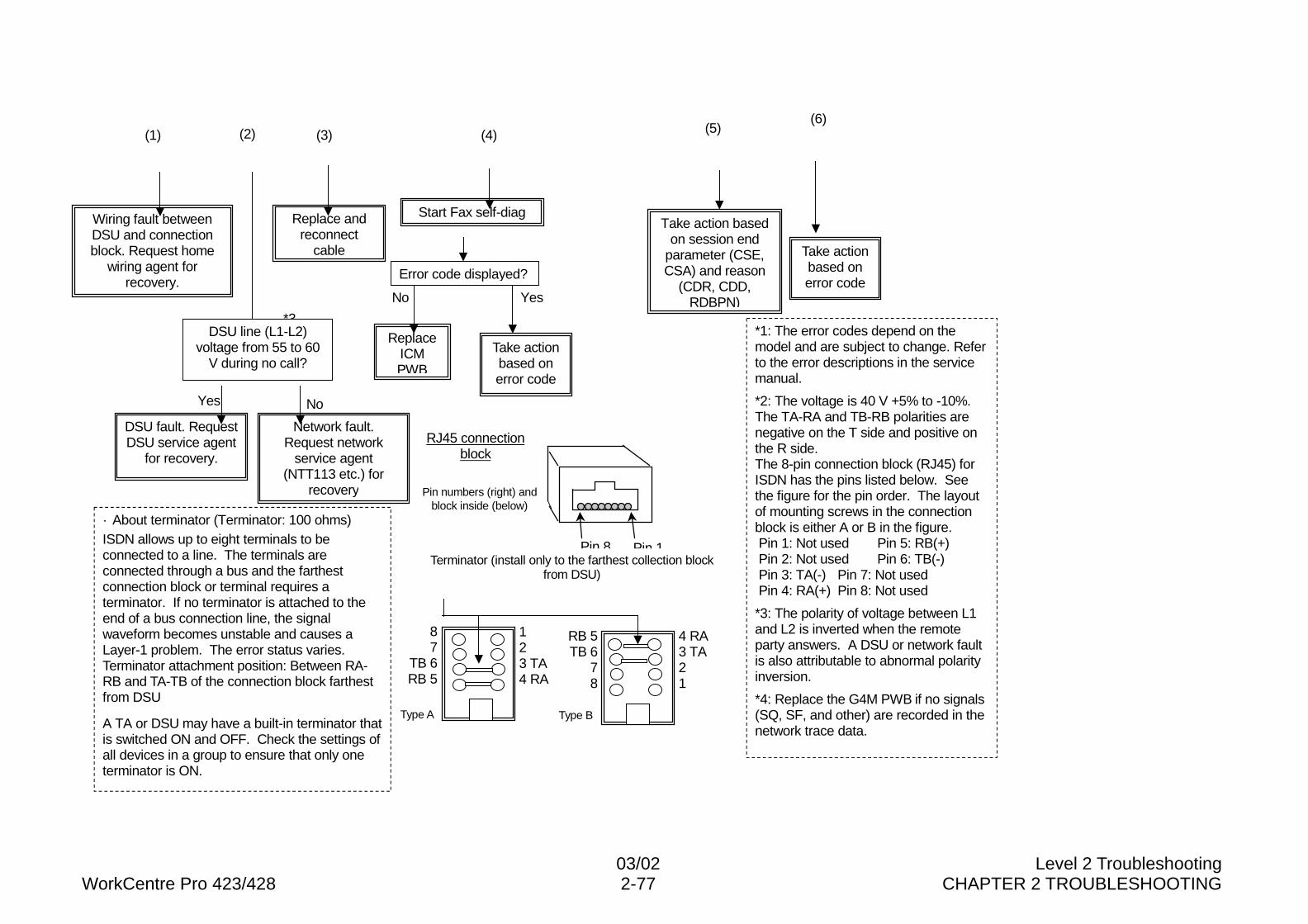
03/02 Level 2 TroubleshootingWorkCentre Pro 423/428 2-77 CHAPTER 2 TROUBLESHOOTING
Type BType A
*3
Take actionbased onerror code
Take action basedon session end
parameter (CSE,CSA) and reason
(CDR, CDD,RDBPN)
*1: The error codes depend on themodel and are subject to change. Referto the error descriptions in the servicemanual.
*2: The voltage is 40 V +5% to -10%.The TA-RA and TB-RB polarities arenegative on the T side and positive onthe R side.The 8-pin connection block (RJ45) forISDN has the pins listed below. Seethe figure for the pin order. The layoutof mounting screws in the connectionblock is either A or B in the figure. Pin 1: Not used Pin 5: RB(+) Pin 2: Not used Pin 6: TB(-) Pin 3: TA(-) Pin 7: Not used Pin 4: RA(+) Pin 8: Not used
*3: The polarity of voltage between L1and L2 is inverted when the remoteparty answers. A DSU or network faultis also attributable to abnormal polarityinversion.
*4: Replace the G4M PWB if no signals(SQ, SF, and other) are recorded in thenetwork trace data.
· About terminator (Terminator: 100 ohms)ISDN allows up to eight terminals to beconnected to a line. The terminals areconnected through a bus and the farthestconnection block or terminal requires aterminator. If no terminator is attached to theend of a bus connection line, the signalwaveform becomes unstable and causes aLayer-1 problem. The error status varies.Terminator attachment position: Between RA-RB and TA-TB of the connection block farthestfrom DSU
A TA or DSU may have a built-in terminator thatis switched ON and OFF. Check the settings ofall devices in a group to ensure that only oneterminator is ON.
No
Start Fax self-diag
Take actionbased onerror code
Yes
ReplaceICMPWB
Replace andreconnect
cable
Yes No
Network fault.Request network
service agent(NTT113 etc.) for
recovery
Wiring fault betweenDSU and connectionblock. Request home
wiring agent forrecovery.
DSU fault. RequestDSU service agent
for recovery.
RJ45 connectionblock
Pin 1Pin 8Terminator (install only to the farthest collection block
from DSU)
4 RA3 TA21
RB 5TB 6
78
123 TA4 RA
87
TB 6RB 5
Error code displayed?
Pin numbers (right) andblock inside (below)
(1) (3) (4) (5)(2)(6)
DSU line (L1-L2)voltage from 55 to 60
V during no call?
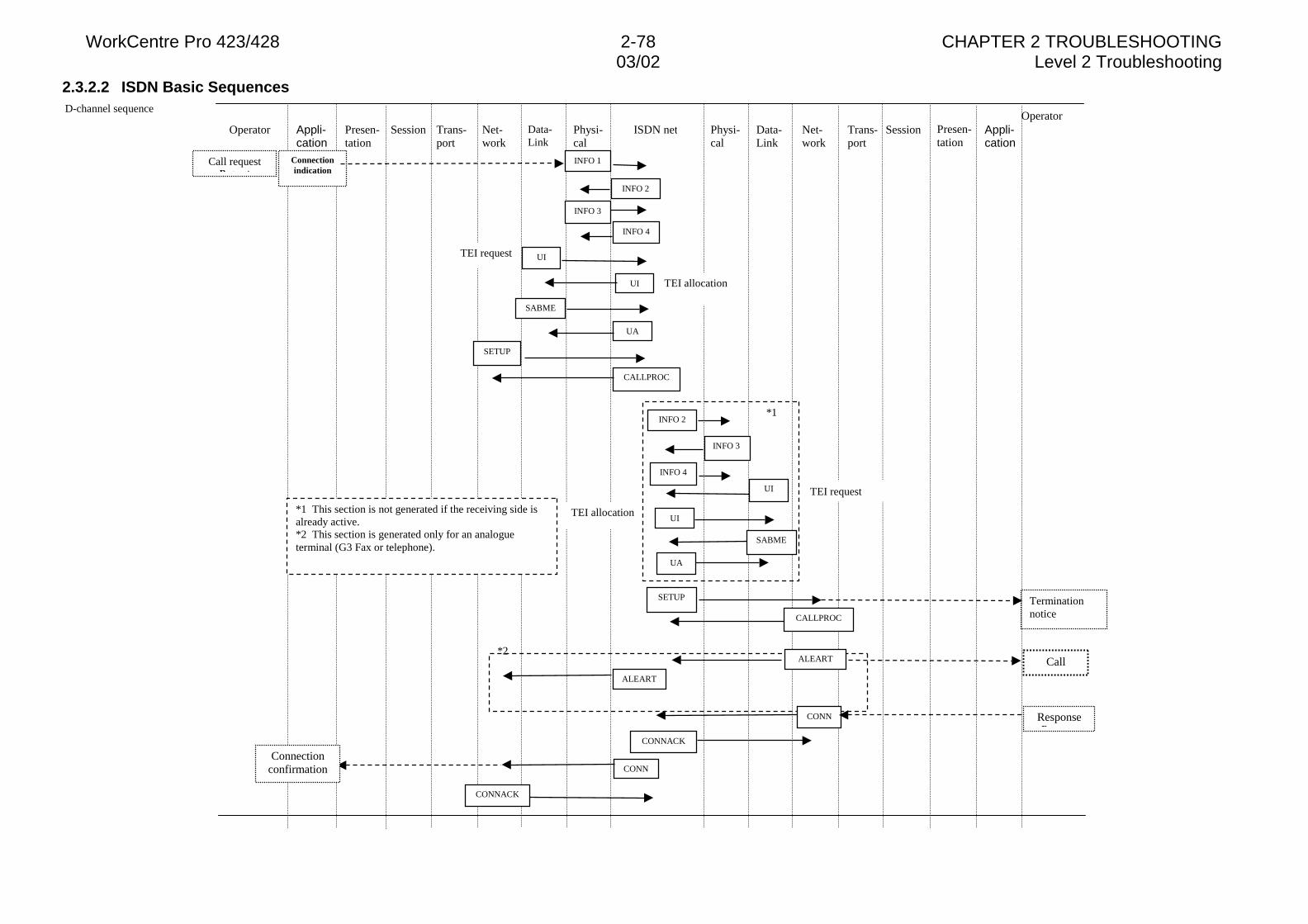
WorkCentre Pro 423/428 2-78 CHAPTER 2 TROUBLESHOOTING03/02 Level 2 Troubleshooting
2.3.2.2 ISDN Basic Sequences D-channel sequence
Operator Presen-tation
Appli-cation
Session Trans-port
Net-work
Data-Link
Physi-cal
ISDN net Physi-cal
Data-Link
Net-work
Trans-port
Session Presen-tation
Appli-cation
Operator
ALEART
CONNConnection
confirmationC
Call requestReq est
Connectionindication
INFO 4
UA
CALLPROC
INFO 2
INFO 3
INFO 4
SETUP Terminationnotice
UI
CONN
CONNACK
ResponseR
TEI allocation
TEI request UI
SABME
UI
TEI request
TEI allocationUI
CallALEART
CONNACK
CALLPROC
SETUP
INFO 2
INFO 1
INFO 3
*1
*2
*1 This section is not generated if the receiving side isalready active.*2 This section is generated only for an analogueterminal (G3 Fax or telephone).
SABME
UA
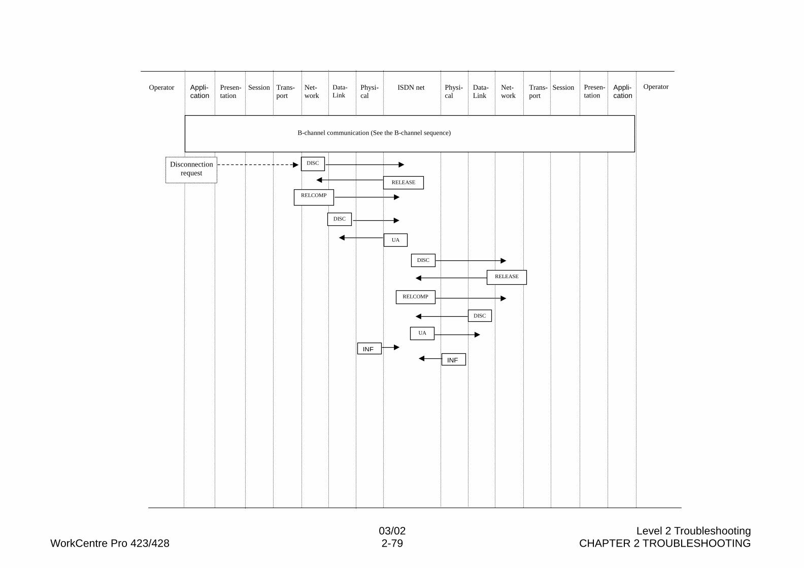
03/02 Level 2 TroubleshootingWorkCentre Pro 423/428 2-79 CHAPTER 2 TROUBLESHOOTING
Operator Presen-tation
Appli-cation
Session Trans-port
Net-work
Data-Link
Physi-cal
ISDN net Physi-cal
Data-Link
Net-work
Trans-port
Session Presen-tation
Appli-cation
Operator
DISC
RELEASE
DISC
UA
DISC
RELCOMP
DISC
UA
INF
B-channel communication (See the B-channel sequence)
Disconnectionrequest
RELCOMP
RELEASE
INF
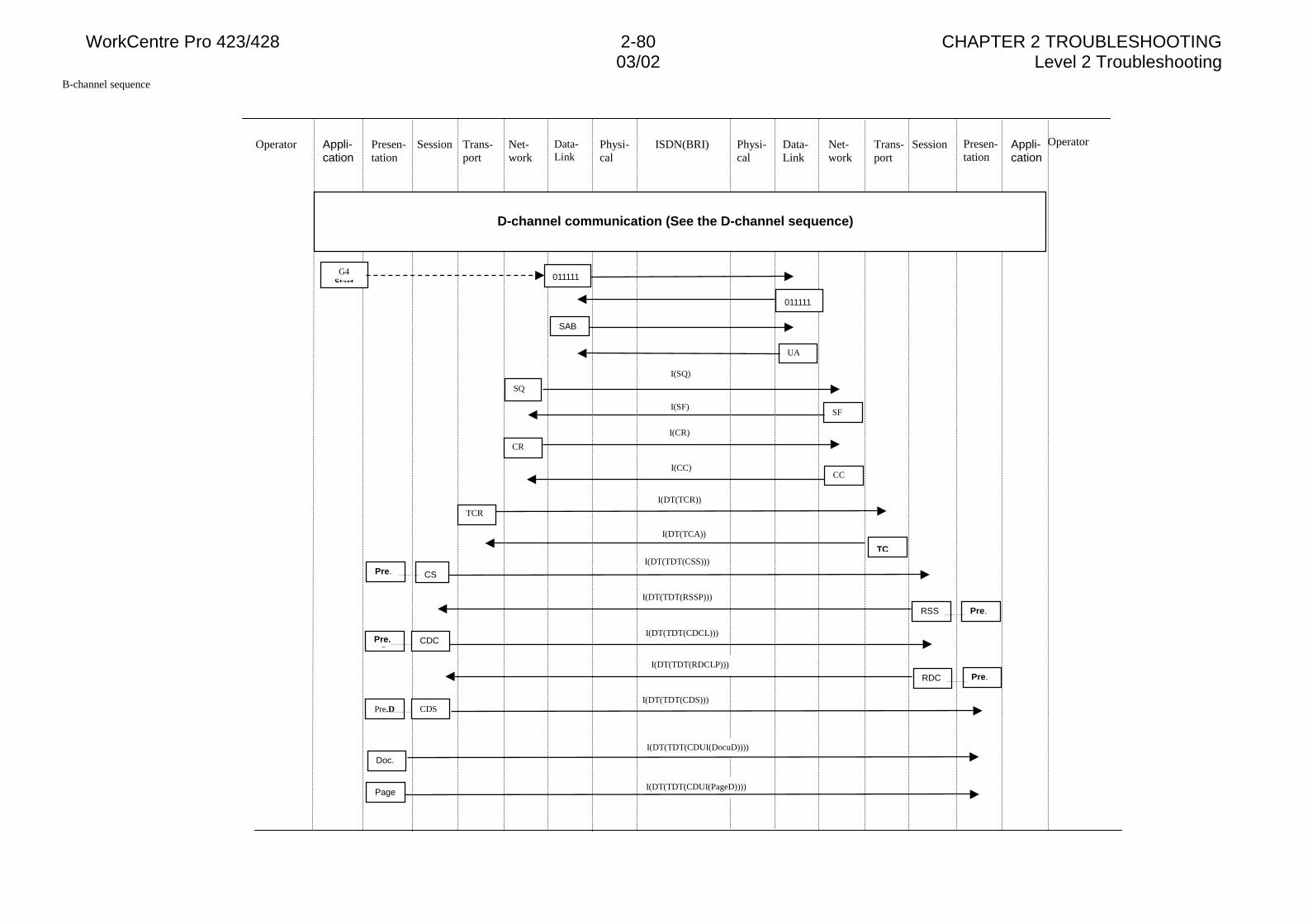
WorkCentre Pro 423/428 2-80 CHAPTER 2 TROUBLESHOOTING03/02 Level 2 Troubleshooting
B-channel sequence
Operator Presen-tation
Appli-cation
Session Trans-port
Net-work
Data-Link
Physi-cal
ISDN(BRI) Physi-cal
Data-Link
Net-work
Trans-port
Session Presen-tation
Appli-cation
Operator
D-channel communication (See the D-channel sequence)
SQ
SF
CR
G4Start
TCR
011111
SAB
CC
011111
TC
Pre.D
Doc.
Pre.RDC
Pre.RSS
CDC
CDS
I(SQ)
I(SF)
I(CR)
I(CC)
I(DT(TCR))
I(DT(TCA))
Pre.D
CSPre.I(DT(TDT(CSS)))
I(DT(TDT(RSSP)))
I(DT(TDT(CDCL)))
I(DT(TDT(RDCLP)))
I(DT(TDT(CDS)))
I(DT(TDT(CDUI(DocuD))))
I(DT(TDT(CDUI(PageD))))Page
UA
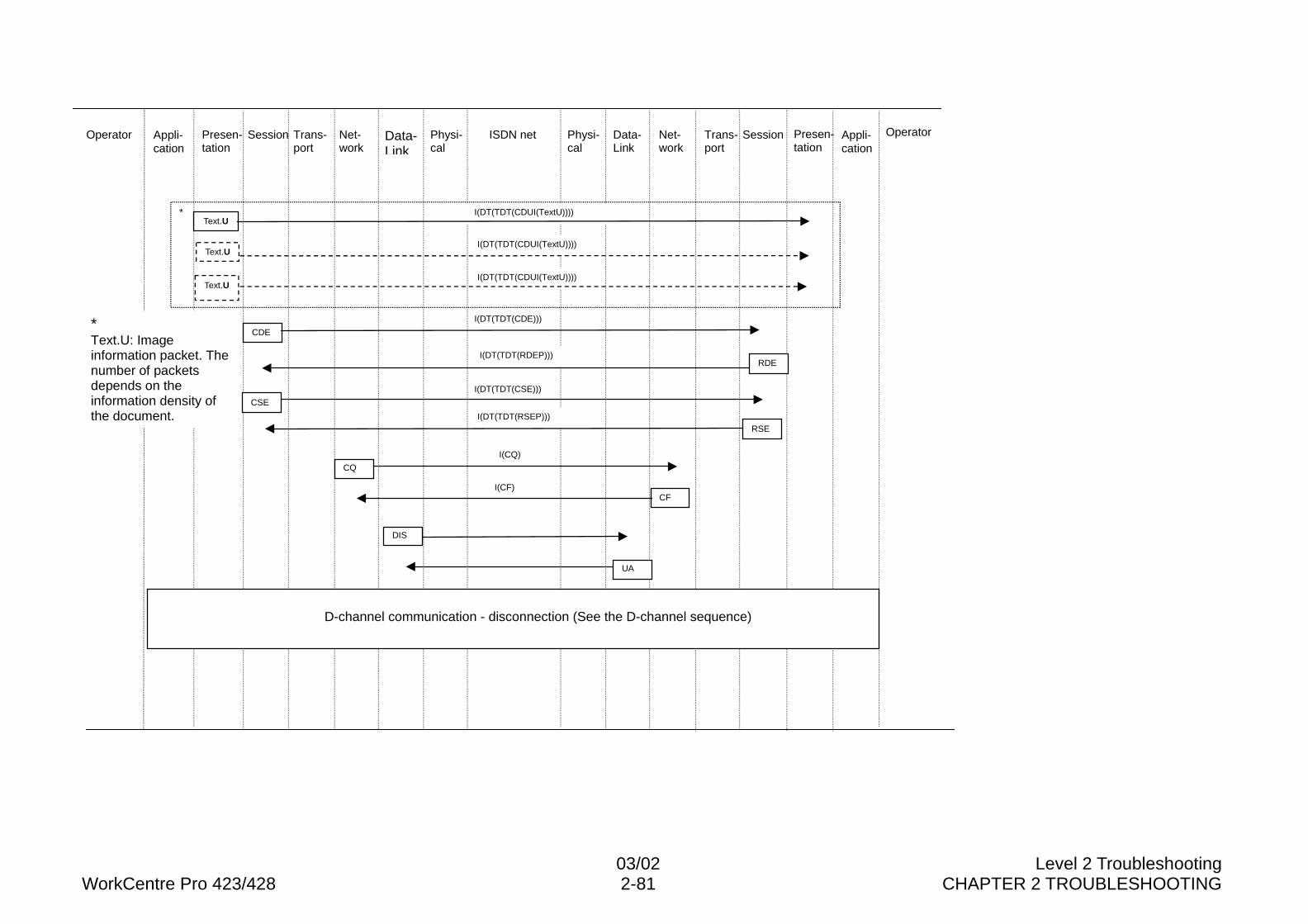
03/02 Level 2 TroubleshootingWorkCentre Pro 423/428 2-81 CHAPTER 2 TROUBLESHOOTING
Operator Presen-tation
Appli-cation
Session Trans-port
Net-work
Data-Link
Physi-cal
ISDN net Physi-cal
Data-Link
Net-work
Trans-port
Session Presen-tation
Appli-cation
Operator
*
UA
RDE
CF
Text.U
Text.U
Text.U
I(DT(TDT(CDUI(TextU))))
I(DT(TDT(CDUI(TextU))))
I(DT(TDT(CDUI(TextU))))
CDE
I(DT(TDT(CDE)))
I(DT(TDT(RDEP)))
I(DT(TDT(CSE)))
I(DT(TDT(RSEP)))
I(CQ)
I(CF)
DIS
CSE
RSE
D-channel communication - disconnection (See the D-channel sequence)
*Text.U: Imageinformation packet. Thenumber of packetsdepends on theinformation density ofthe document.
CQ
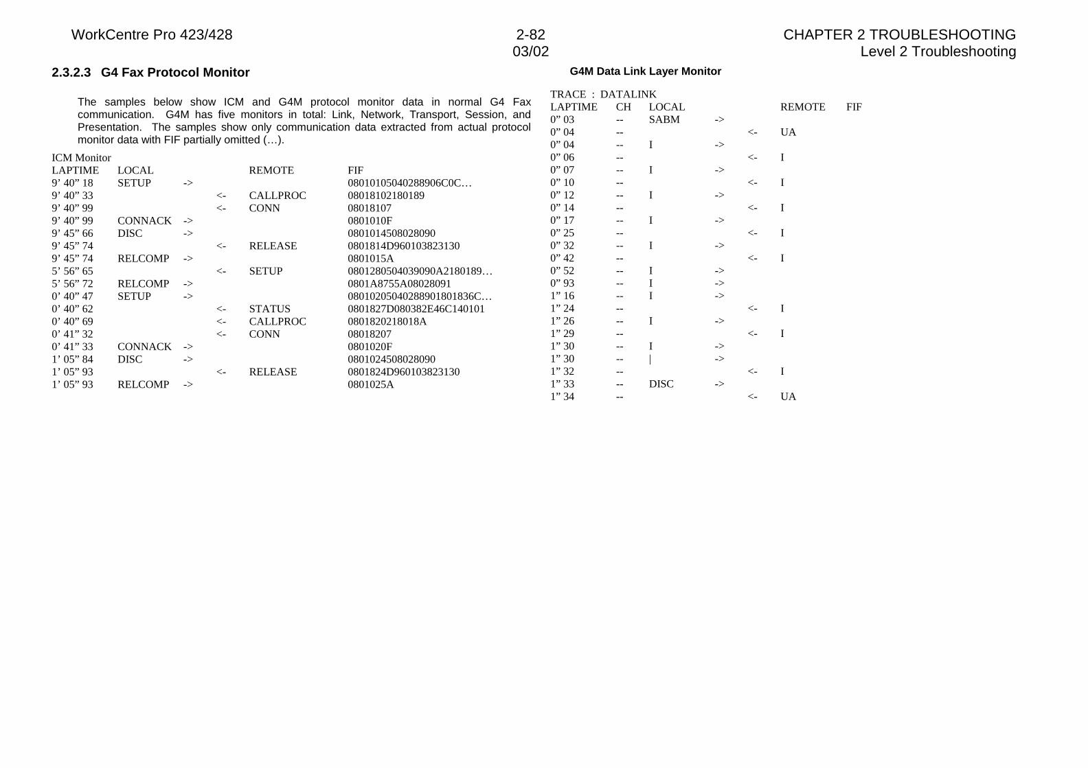
WorkCentre Pro 423/428 2-82 CHAPTER 2 TROUBLESHOOTING03/02 Level 2 Troubleshooting
2.3.2.3 G4 Fax Protocol Monitor
The samples below show ICM and G4M protocol monitor data in normal G4 Faxcommunication. G4M has five monitors in total: Link, Network, Transport, Session, andPresentation. The samples show only communication data extracted from actual protocolmonitor data with FIF partially omitted (…).
ICM MonitorLAPTIME LOCAL REMOTE FIF9’ 40” 18 SETUP -> 08010105040288906C0C…9’ 40” 33 <- CALLPROC 080181021801899’ 40” 99 <- CONN 080181079’ 40” 99 CONNACK -> 0801010F9’ 45” 66 DISC -> 08010145080280909’ 45” 74 <- RELEASE 0801814D9601038231309’ 45” 74 RELCOMP -> 0801015A5’ 56” 65 <- SETUP 0801280504039090A2180189…5’ 56” 72 RELCOMP -> 0801A8755A080280910’ 40” 47 SETUP -> 08010205040288901801836C…0’ 40” 62 <- STATUS 0801827D080382E46C1401010’ 40” 69 <- CALLPROC 0801820218018A0’ 41” 32 <- CONN 080182070’ 41” 33 CONNACK -> 0801020F1’ 05” 84 DISC -> 08010245080280901’ 05” 93 <- RELEASE 0801824D9601038231301’ 05” 93 RELCOMP -> 0801025A
G4M Data Link Layer Monitor
TRACE : DATALINKLAPTIME CH LOCAL REMOTE FIF0” 03 -- SABM ->0” 04 -- <- UA0” 04 -- I ->0” 06 -- <- I0” 07 -- I ->0” 10 -- <- I0” 12 -- I ->0” 14 -- <- I0” 17 -- I ->0” 25 -- <- I0” 32 -- I ->0” 42 -- <- I0” 52 -- I ->0” 93 -- I ->1” 16 -- I ->1” 24 -- <- I1” 26 -- I ->1” 29 -- <- I1” 30 -- I ->1” 30 -- | ->1” 32 -- <- I1” 33 -- DISC ->1” 34 -- <- UA
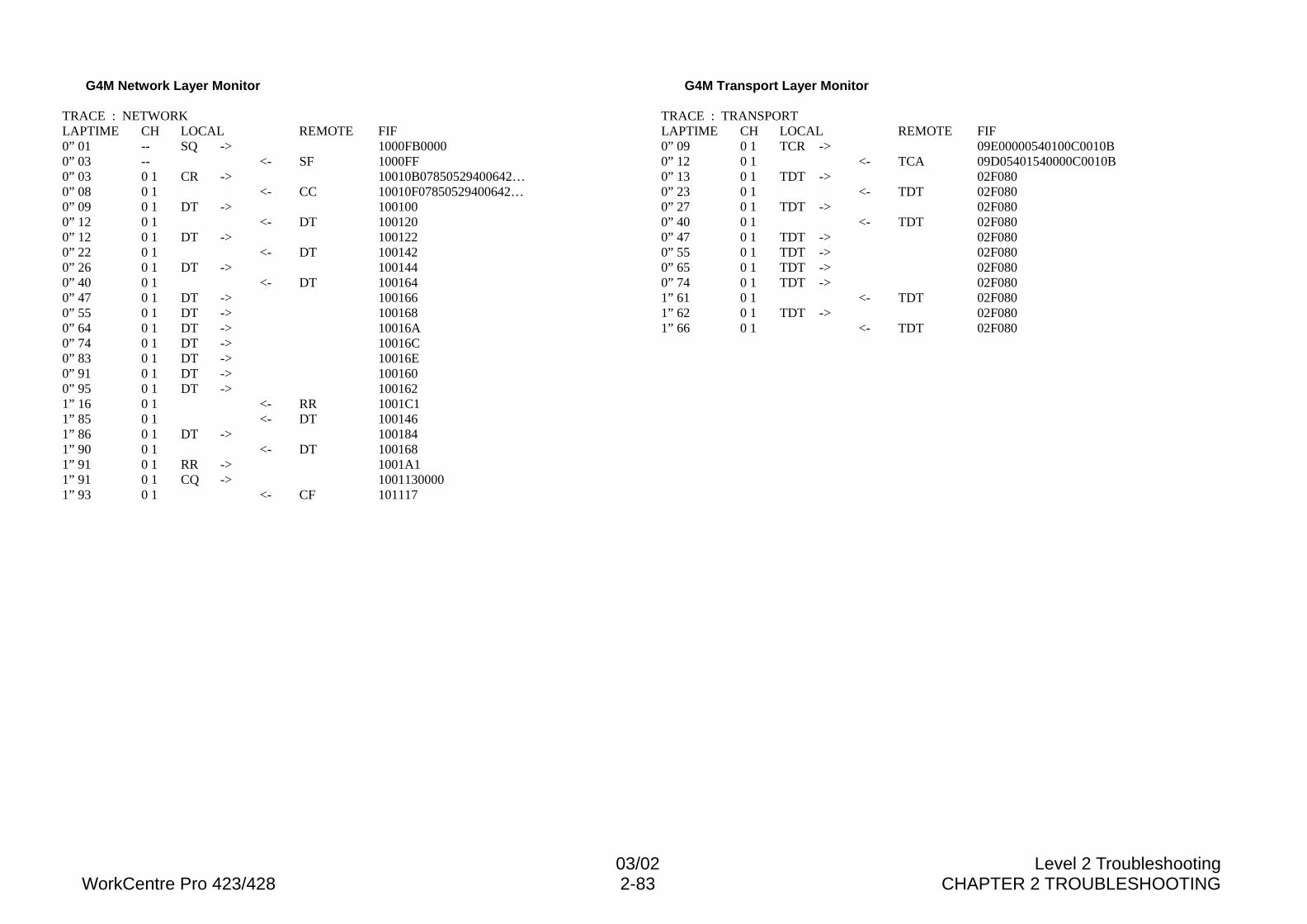
03/02 Level 2 TroubleshootingWorkCentre Pro 423/428 2-83 CHAPTER 2 TROUBLESHOOTING
G4M Network Layer Monitor
TRACE : NETWORKLAPTIME CH LOCAL REMOTE FIF0” 01 -- SQ -> 1000FB00000” 03 -- <- SF 1000FF0” 03 0 1 CR -> 10010B07850529400642…0” 08 0 1 <- CC 10010F07850529400642…0” 09 0 1 DT -> 1001000” 12 0 1 <- DT 1001200” 12 0 1 DT -> 1001220” 22 0 1 <- DT 1001420” 26 0 1 DT -> 1001440” 40 0 1 <- DT 1001640” 47 0 1 DT -> 1001660” 55 0 1 DT -> 1001680” 64 0 1 DT -> 10016A0” 74 0 1 DT -> 10016C0” 83 0 1 DT -> 10016E0” 91 0 1 DT -> 1001600” 95 0 1 DT -> 1001621” 16 0 1 <- RR 1001C11” 85 0 1 <- DT 1001461” 86 0 1 DT -> 1001841” 90 0 1 <- DT 1001681” 91 0 1 RR -> 1001A11” 91 0 1 CQ -> 10011300001” 93 0 1 <- CF 101117
G4M Transport Layer Monitor
TRACE : TRANSPORTLAPTIME CH LOCAL REMOTE FIF0” 09 0 1 TCR -> 09E00000540100C0010B0” 12 0 1 <- TCA 09D05401540000C0010B0” 13 0 1 TDT -> 02F0800” 23 0 1 <- TDT 02F0800” 27 0 1 TDT -> 02F0800” 40 0 1 <- TDT 02F0800” 47 0 1 TDT -> 02F0800” 55 0 1 TDT -> 02F0800” 65 0 1 TDT -> 02F0800” 74 0 1 TDT -> 02F0801” 61 0 1 <- TDT 02F0801” 62 0 1 TDT -> 02F0801” 66 0 1 <- TDT 02F080
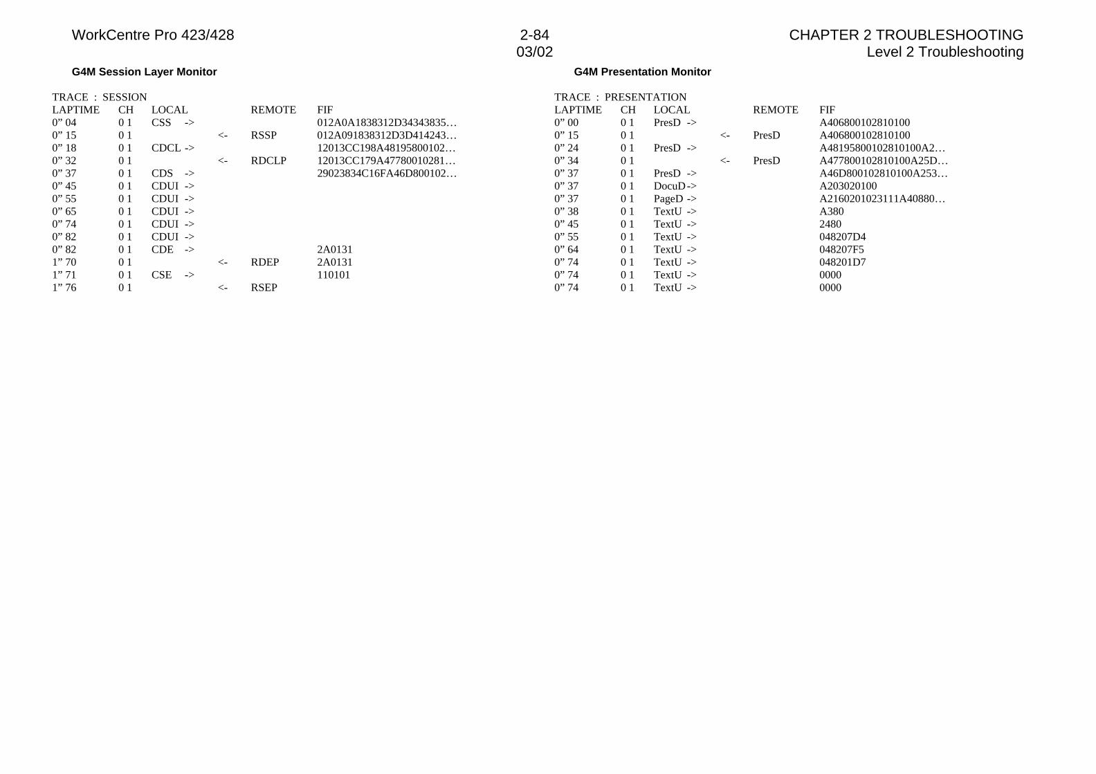
WorkCentre Pro 423/428 2-84 CHAPTER 2 TROUBLESHOOTING03/02 Level 2 Troubleshooting
G4M Session Layer Monitor
TRACE : SESSIONLAPTIME CH LOCAL REMOTE FIF0” 04 0 1 CSS -> 012A0A1838312D34343835…0” 15 0 1 <- RSSP 012A091838312D3D414243…0” 18 0 1 CDCL -> 12013CC198A48195800102…0” 32 0 1 <- RDCLP 12013CC179A47780010281…0” 37 0 1 CDS -> 29023834C16FA46D800102…0” 45 0 1 CDUI ->0” 55 0 1 CDUI ->0” 65 0 1 CDUI ->0” 74 0 1 CDUI ->0” 82 0 1 CDUI ->0” 82 0 1 CDE -> 2A01311” 70 0 1 <- RDEP 2A01311” 71 0 1 CSE -> 1101011” 76 0 1 <- RSEP
G4M Presentation Monitor
TRACE : PRESENTATIONLAPTIME CH LOCAL REMOTE FIF0” 00 0 1 PresD -> A4068001028101000” 15 0 1 <- PresD A4068001028101000” 24 0 1 PresD -> A48195800102810100A2…0” 34 0 1 <- PresD A477800102810100A25D…0” 37 0 1 PresD -> A46D800102810100A253…0” 37 0 1 DocuD-> A2030201000” 37 0 1 PageD -> A2160201023111A40880…0” 38 0 1 TextU -> A3800” 45 0 1 TextU -> 24800” 55 0 1 TextU -> 048207D40” 64 0 1 TextU -> 048207F50” 74 0 1 TextU -> 048201D70” 74 0 1 TextU -> 00000” 74 0 1 TextU -> 0000
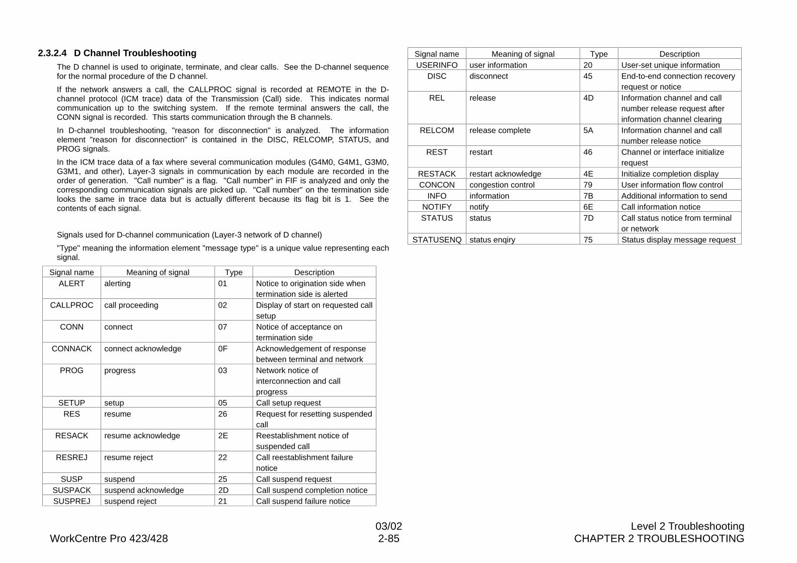
03/02 Level 2 TroubleshootingWorkCentre Pro 423/428 2-85 CHAPTER 2 TROUBLESHOOTING
2.3.2.4 D Channel TroubleshootingThe D channel is used to originate, terminate, and clear calls. See the D-channel sequencefor the normal procedure of the D channel.
If the network answers a call, the CALLPROC signal is recorded at REMOTE in the D-channel protocol (ICM trace) data of the Transmission (Call) side. This indicates normalcommunication up to the switching system. If the remote terminal answers the call, theCONN signal is recorded. This starts communication through the B channels.
In D-channel troubleshooting, "reason for disconnection" is analyzed. The informationelement "reason for disconnection" is contained in the DISC, RELCOMP, STATUS, andPROG signals.
In the ICM trace data of a fax where several communication modules (G4M0, G4M1, G3M0,G3M1, and other), Layer-3 signals in communication by each module are recorded in theorder of generation. "Call number" is a flag. "Call number" in FIF is analyzed and only thecorresponding communication signals are picked up. "Call number" on the termination sidelooks the same in trace data but is actually different because its flag bit is 1. See thecontents of each signal.
Signals used for D-channel communication (Layer-3 network of D channel)
"Type" meaning the information element "message type" is a unique value representing eachsignal.
Signal name Meaning of signal Type DescriptionALERT alerting 01 Notice to origination side when
termination side is alertedCALLPROC call proceeding 02 Display of start on requested call
setupCONN connect 07 Notice of acceptance on
termination sideCONNACK connect acknowledge 0F Acknowledgement of response
between terminal and networkPROG progress 03 Network notice of
interconnection and callprogress
SETUP setup 05 Call setup requestRES resume 26 Request for resetting suspended
callRESACK resume acknowledge 2E Reestablishment notice of
suspended callRESREJ resume reject 22 Call reestablishment failure
noticeSUSP suspend 25 Call suspend request
SUSPACK suspend acknowledge 2D Call suspend completion noticeSUSPREJ suspend reject 21 Call suspend failure notice
Signal name Meaning of signal Type DescriptionUSERINFO user information 20 User-set unique information
DISC disconnect 45 End-to-end connection recoveryrequest or notice
REL release 4D Information channel and callnumber release request afterinformation channel clearing
RELCOM release complete 5A Information channel and callnumber release notice
REST restart 46 Channel or interface initializerequest
RESTACK restart acknowledge 4E Initialize completion displayCONCON congestion control 79 User information flow control
INFO information 7B Additional information to sendNOTIFY notify 6E Call information noticeSTATUS status 7D Call status notice from terminal
or networkSTATUSENQ status enqiry 75 Status display message request
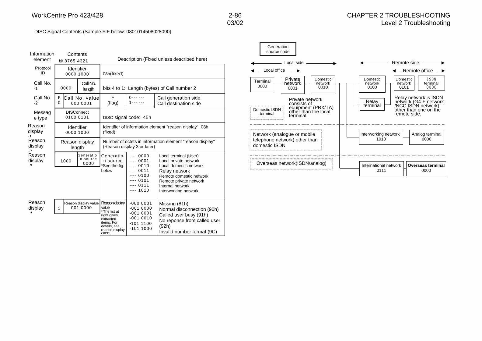
WorkCentre Pro 423/428 2-86 CHAPTER 2 TROUBLESHOOTING03/02 Level 2 Troubleshooting
DISC Signal Contents (Sample FIF below: 0801014508028090)
bit 8765 4321
Number of octets in information element "reason display"(Reason display 3 or later)
Identifier of information element "reason display": 08h(fixed)
DISC signal code: 45h
Reasondisplay-4
Reasondisplay-3
Reasondisplay-2
Reasondisplay-1
Message type
Call No.-2
Call No.-1
ProtocolID
DISConnect0100 0101
0000
Reason displaylength
F0
F(flag)
0--- ---1--- ---
Call generation sideCall destination side
Identifier0000 1000
1000Generation source
*See the fig.below
---- 0000---- 0001---- 0010---- 0011---- 0100---- 0101---- 0111---- 1010
Local terminal (User)Local private networkLocal domestic networkRelay networkRemote domestic networkRemote private networkInternal networkInterworking network
1Reason displayvalue* The list atright givesextracteditems. Fordetails, seereason displayQ931.
-000 0001-001 0000-001 0001-001 0010-101 1100-101 1000
Missing (81h)Normal disconnection (90h)Called user busy (91h)No reponse from called user(92h)Invalid number format (9C)
Generat ion source
0000
Reason display value001 0000
Call No. value000 0001
Informationelement Description (Fixed unless described here)
Contents
08h(fixed)Identifier
0000 1000
bits 4 to 1: Length (bytes) of Call number 2Call No.length
Private networkconsists ofequipment (PBX/TA)other than the localterminal.
Relay network is ISDNnetwork (G4-F network/NCC ISDN network)other than one on theremote side.
Local office
Terminal0000
Privatenetwork
0001
Domesticnetwork0010
Domesticnetwork0101
Domesticnetwork0100
Interworking network1010
Analog terminal0000
Relayterminal
International network0111
Overseas terminal0000
Local side
Remote office
Remote side
Overseas network(ISDN/analog)
Network (analogue or mobiletelephone network) other thandomestic ISDN
Domestic ISDNterminal
,6'1terminal����
Generationsource code
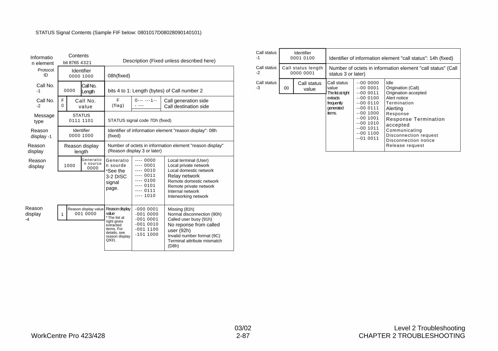
03/02 Level 2 TroubleshootingWorkCentre Pro 423/428 2-87 CHAPTER 2 TROUBLESHOOTING
STATUS Signal Contents (Sample FIF below: 0801017D08028090140101)
bit 8765 4321
Number of octets in information element "reason display"(Reason display 3 or later)
Identifier of information element "reason display": 08h(fixed)
STATUS signal code 7Dh (fixed)
Reasondisplay-4
Reasondisplay
Reasondisplay
Reasondisplay -1
Messagetype
Call No.-2
Call No.-1
ProtocolID
STATUS0111 1101
0000
Reason displaylength
F0
F(f lag)
0--- ---1--- ---
Call generation sideCall destination side
Identifier0000 1000
1000Generation sourde*See the3-2 DISCsignalpage.
---- 0000---- 0001---- 0010---- 0011---- 0100---- 0101---- 0111---- 1010
Local terminal (User)Local private networkLocal domestic networkRelay networkRemote domestic networkRemote private networkInternal networkInterworking network
1Reason displayvalue* The list atright givesextracteditems. Fordetails, seereason displayQ931.
-000 0001-001 0000-001 0001-001 0010-001 1100-101 1000
Missing (81h)Normal disconnection (90h)Called user busy (91h)No reponse from calleduser (92h)Invalid number format (9C)Terminal attribute mismatch(D8h)
Generat ion source
0000
Reason display value001 0000
Call No.value
Information element Description (Fixed unless described here)
08h(fixed)Identifier
0000 1000
bits 4 to 1: Length (bytes) of Call number 2Call No.Length
Contents
Number of octets in information element "call status" (Callstatus 3 or later)
Identifier of information element "call status": 14h (fixed)
Call status-3
Call status-2
Call status-1
Call status length0000 0001
Identifier0001 0100
00Call statusvalueThe list at rightextractsfrequentlygenerateditems.
--00 0000--00 0001--00 0011--00 0100--00 0110--00 0111--00 1000--00 1001--00 1010--00 1011--00 1100--01 0011
IdleOrigination (Call)Origination acceptedAlert noticeTerminationAlertingResponseResponse TerminationacceptedCommunicatingDisconnection requestDisconnection noticeRelease request
Call statusvalue
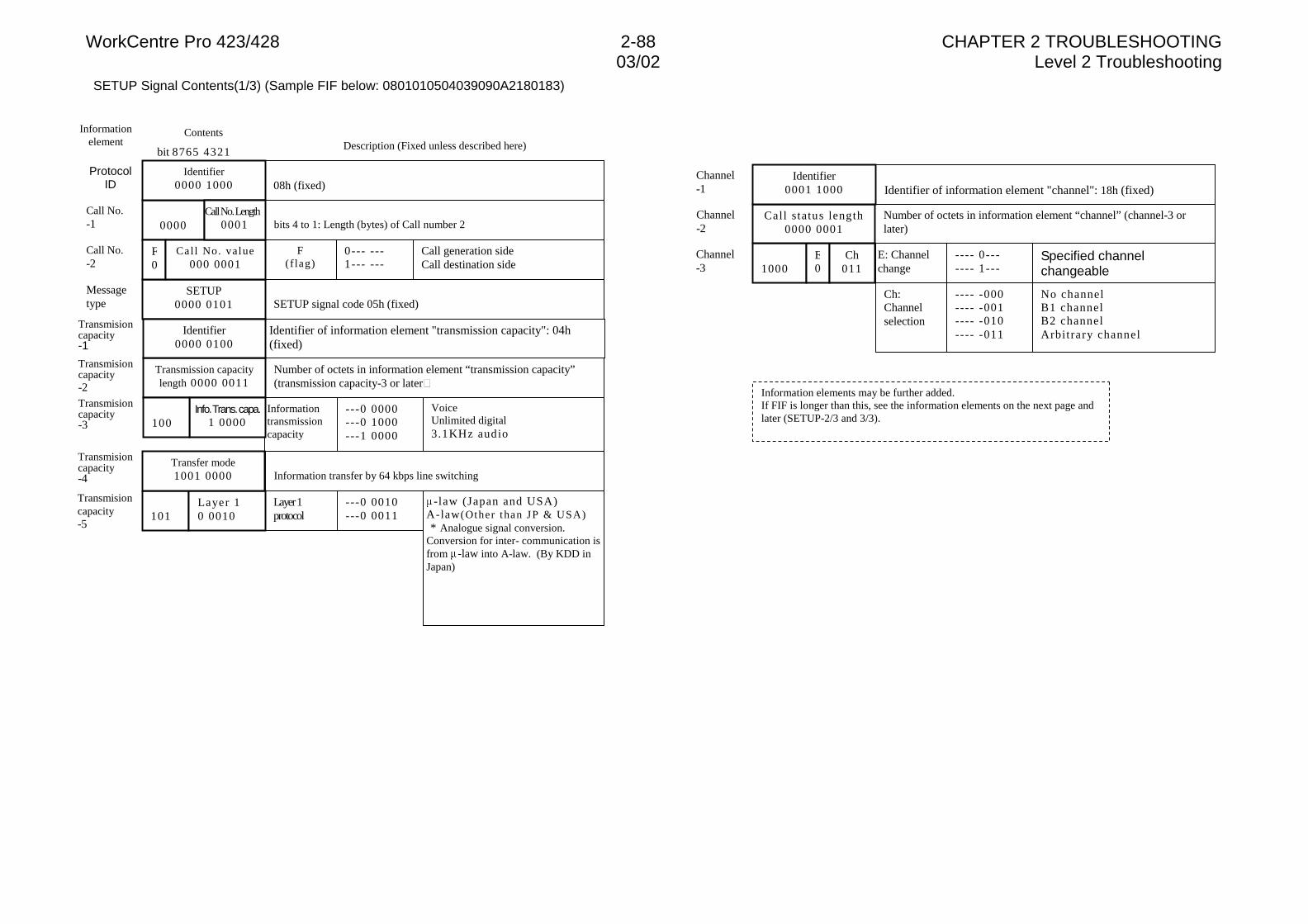
WorkCentre Pro 423/428 2-88 CHAPTER 2 TROUBLESHOOTING03/02 Level 2 Troubleshooting
SETUP Signal Contents(1/3) (Sample FIF below: 0801010504039090A2180183)
bit 8765 4321
Number of octets in information element “transmission capacity”(transmission capacity-3 or later�
Identifier of information element "transmission capacity": 04h(fixed)
SETUP signal code 05h (fixed)
Transmisioncapacity-5
Transmisioncapacity-3
Transmisioncapacity-2
Transmisioncapacity-1
Messagetype
Call No.-2
Call No.-1
ProtocolID
SETUP0000 0101
0000
Transmission capacitylength 0000 0011
F0
F(f lag)
0--- ---1--- ---
Call generation sideCall destination side
Identifier0000 0100
Informationtransmissioncapacity
---0 0000---0 1000---1 0000
VoiceUnlimited digital3.1KHz audio
101Layer 1protocol
---0 0010---0 0011
-law (Japan and USA)A-law(Other than JP & USA) * Analogue signal conversion.Conversion for inter- communication isfrom -law into A-law. (By KDD inJapan)
Info. Trans. capa.1 0000
Call No. value000 0001
Informationelement Description (Fixed unless described here)
Contents
08h (fixed)Identifier
0000 1000
100
Information transfer by 64 kbps line switching
Transmisioncapacity-4
Layer 10 0010
Transfer mode1001 0000
bits 4 to 1: Length (bytes) of Call number 2Call No. Length
0001
Channel-3
Channel-1
Number of octets in information element “channel” (channel-3 orlater)
Identifier of information element "channel": 18h (fixed)
Channel-2
1000E: Channelchange
---- 0------- 1---
Specified channelchangeable
E0
Ch:Channelselection
---- -000---- -001---- -010---- -011
No channelB1 channelB2 channelArbitrary channel
Ch011
Call status length0000 0001
Identifier0001 1000
Information elements may be further added.If FIF is longer than this, see the information elements on the next page andlater (SETUP-2/3 and 3/3).
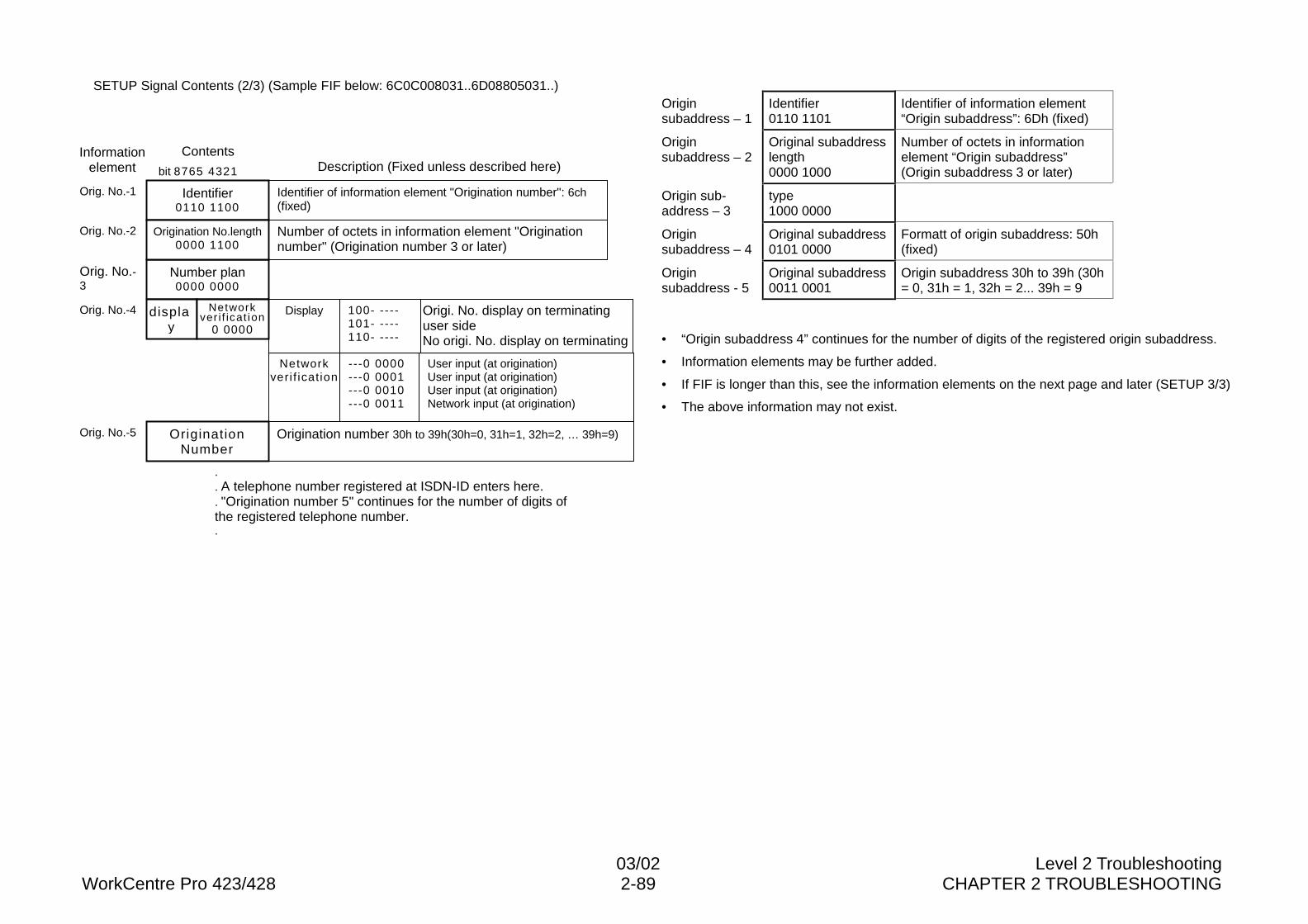
03/02 Level 2 TroubleshootingWorkCentre Pro 423/428 2-89 CHAPTER 2 TROUBLESHOOTING
SETUP Signal Contents (2/3) (Sample FIF below: 6C0C008031..6D08805031..)Originsubaddress – 1
Identifier0110 1101
Identifier of information element“Origin subaddress”: 6Dh (fixed)
Originsubaddress – 2
Original subaddresslength0000 1000
Number of octets in informationelement “Origin subaddress”(Origin subaddress 3 or later)
Origin sub-address – 3
type1000 0000
Originsubaddress – 4
Original subaddress0101 0000
Formatt of origin subaddress: 50h(fixed)
Originsubaddress - 5
Original subaddress0011 0001
Origin subaddress 30h to 39h (30h= 0, 31h = 1, 32h = 2... 39h = 9
• “Origin subaddress 4” continues for the number of digits of the registered origin subaddress.
• Information elements may be further added.
• If FIF is longer than this, see the information elements on the next page and later (SETUP 3/3)
• The above information may not exist.
.
. A telephone number registered at ISDN-ID enters here.
. "Origination number 5" continues for the number of digits ofthe registered telephone number..
bit 8765 4321
Informationelement Description (Fixed unless described here)
Contents
Number of octets in information element "Originationnumber" (Origination number 3 or later)
Identifier of information element "Origination number": 6ch(fixed)
Orig. No.-3
Orig. No.-2
Number plan0000 0000
Orig. No.-4 display
Display 100- ----101- ----110- ----
Origi. No. display on terminatinguser sideNo origi. No. display on terminating
Networkveri f ication
---0 0000---0 0001---0 0010---0 0011
User input (at origination)User input (at origination)User input (at origination)Network input (at origination)
Origination number 30h to 39h(30h=0, 31h=1, 32h=2, … 39h=9)Orig. No.-5
Orig. No.-1 Identifier0110 1100
Origination No.length0000 1100
Networkver i f icat ion
0 0000
OriginationNumber
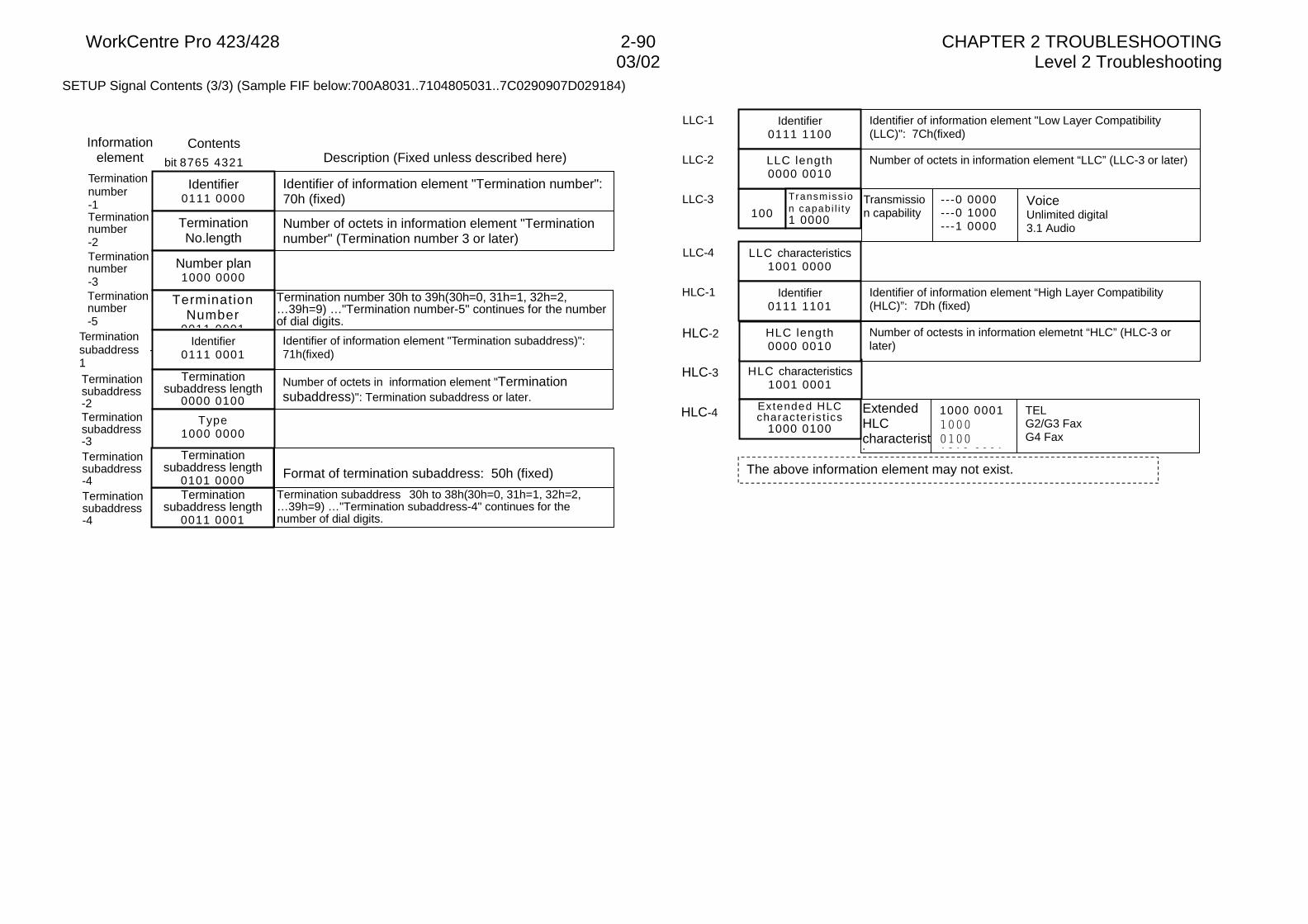
WorkCentre Pro 423/428 2-90 CHAPTER 2 TROUBLESHOOTING03/02 Level 2 Troubleshooting
SETUP Signal Contents (3/3) (Sample FIF below:700A8031..7104805031..7C0290907D029184)
bit 8765 4321
Informationelement Description (Fixed unless described here)
Contents
Number of octets in information element "Terminationnumber" (Termination number 3 or later)
Identifier of information element "Termination number":70h (fixed)
Terminationnumber-3
Terminationnumber-2
Termination number 30h to 39h(30h=0, 31h=1, 32h=2,…39h=9) …"Termination number-5" continues for the numberof dial digits.
Terminationnumber-5
Terminationnumber-1
Number of octets in information element "Terminationsubaddress)": Termination subaddress or later.
Identifier of information element "Termination subaddress)":71h(fixed)
Terminationsubaddress-3
Terminationsubaddress-2
Termination subaddress 30h to 38h(30h=0, 31h=1, 32h=2,…39h=9) …"Termination subaddress-4" continues for thenumber of dial digits.
Terminationsubaddress-4
Terminationsubaddress -1
Identifier0111 0000
TerminationNo.length
Number plan1000 0000
TerminationNumber
0011 0001Identifier
0111 0001
Terminationsubaddress length
0000 0100
Type1000 0000
Terminationsubaddress length
0011 0001
Format of termination subaddress: 50h (fixed)Terminationsubaddress-4
Terminationsubaddress length
0101 0000
Number of octets in information element “LLC” (LLC-3 or later)
Identifier of information element "Low Layer Compatibility(LLC)": 7Ch(fixed)
LLC-3
LLC-2
100
LLC-1 Identifier0111 1100
LLC length0000 0010
LLC-4 LLC characteristics1001 0000
Number of octests in information elemetnt “HLC” (HLC-3 orlater)
Identifier of information element “High Layer Compatibility(HLC)”: 7Dh (fixed)
HLC-3
HLC-2
HLC characteristics1001 0001
HLC-1 Identifier0111 1101
HLC length0000 0010
HLC-4
Transmission capability
---0 0000---0 1000---1 0000
VoiceUnlimited digital3.1 Audio
Transmiss ion capabi l i ty1 0000
ExtendedHLCcharacteristics
1000 0001��������1010 0001
TELG2/G3 FaxG4 Fax
The above information element may not exist.
Extended HLCcharacter is t ics
1000 0100
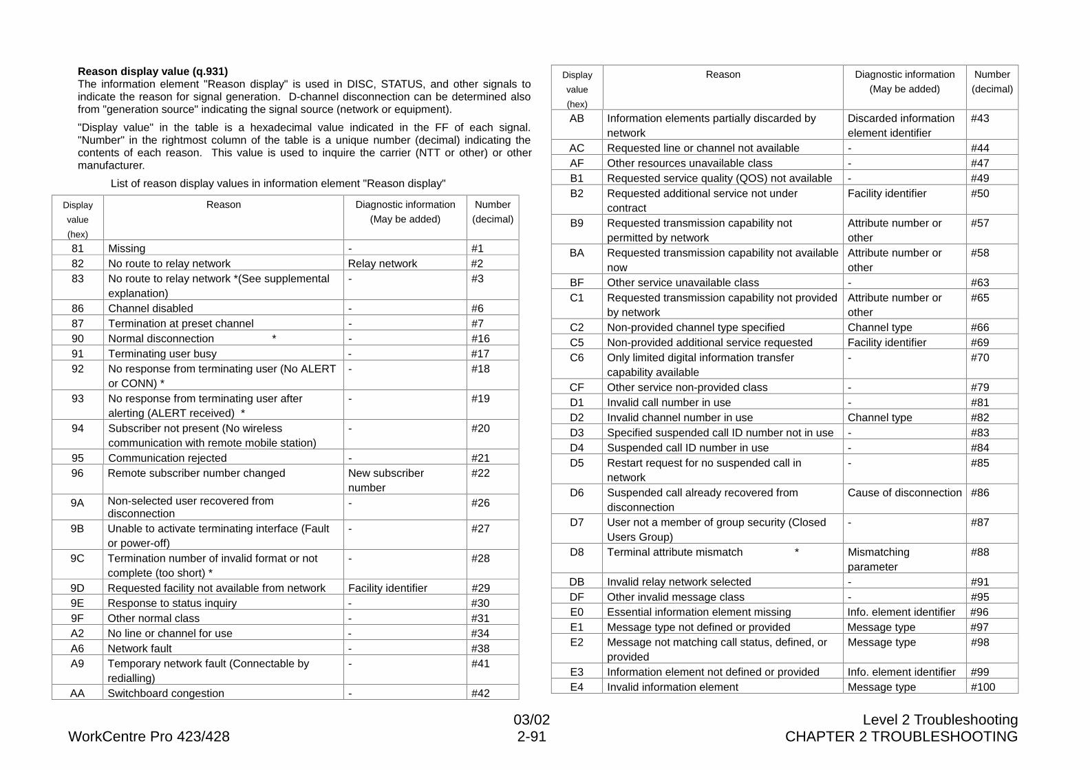
03/02 Level 2 TroubleshootingWorkCentre Pro 423/428 2-91 CHAPTER 2 TROUBLESHOOTING
Reason display value (q.931)The information element "Reason display" is used in DISC, STATUS, and other signals toindicate the reason for signal generation. D-channel disconnection can be determined alsofrom "generation source" indicating the signal source (network or equipment).
"Display value" in the table is a hexadecimal value indicated in the FF of each signal."Number" in the rightmost column of the table is a unique number (decimal) indicating thecontents of each reason. This value is used to inquire the carrier (NTT or other) or othermanufacturer.
List of reason display values in information element "Reason display"
Display
value
(hex)
Reason Diagnostic information
(May be added)
Number
(decimal)
81 Missing - #182 No route to relay network Relay network #283 No route to relay network *(See supplemental
explanation)- #3
86 Channel disabled - #687 Termination at preset channel - #790 Normal disconnection * - #1691 Terminating user busy - #1792 No response from terminating user (No ALERT
or CONN) *- #18
93 No response from terminating user afteralerting (ALERT received) *
- #19
94 Subscriber not present (No wirelesscommunication with remote mobile station)
- #20
95 Communication rejected - #2196 Remote subscriber number changed New subscriber
number#22
9A Non-selected user recovered fromdisconnection
- #26
9B Unable to activate terminating interface (Faultor power-off)
- #27
9C Termination number of invalid format or notcomplete (too short) *
- #28
9D Requested facility not available from network Facility identifier #299E Response to status inquiry - #309F Other normal class - #31A2 No line or channel for use - #34A6 Network fault - #38A9 Temporary network fault (Connectable by
redialling)- #41
AA Switchboard congestion - #42
Display
value
(hex)
Reason Diagnostic information
(May be added)
Number
(decimal)
AB Information elements partially discarded bynetwork
Discarded informationelement identifier
#43
AC Requested line or channel not available - #44AF Other resources unavailable class - #47B1 Requested service quality (QOS) not available - #49B2 Requested additional service not under
contractFacility identifier #50
B9 Requested transmission capability notpermitted by network
Attribute number orother
#57
BA Requested transmission capability not availablenow
Attribute number orother
#58
BF Other service unavailable class - #63C1 Requested transmission capability not provided
by networkAttribute number orother
#65
C2 Non-provided channel type specified Channel type #66C5 Non-provided additional service requested Facility identifier #69C6 Only limited digital information transfer
capability available- #70
CF Other service non-provided class - #79D1 Invalid call number in use - #81D2 Invalid channel number in use Channel type #82D3 Specified suspended call ID number not in use - #83D4 Suspended call ID number in use - #84D5 Restart request for no suspended call in
network- #85
D6 Suspended call already recovered fromdisconnection
Cause of disconnection #86
D7 User not a member of group security (ClosedUsers Group)
- #87
D8 Terminal attribute mismatch * Mismatchingparameter
#88
DB Invalid relay network selected - #91DF Other invalid message class - #95E0 Essential information element missing Info. element identifier #96E1 Message type not defined or provided Message type #97E2 Message not matching call status, defined, or
providedMessage type #98
E3 Information element not defined or provided Info. element identifier #99E4 Invalid information element Message type #100
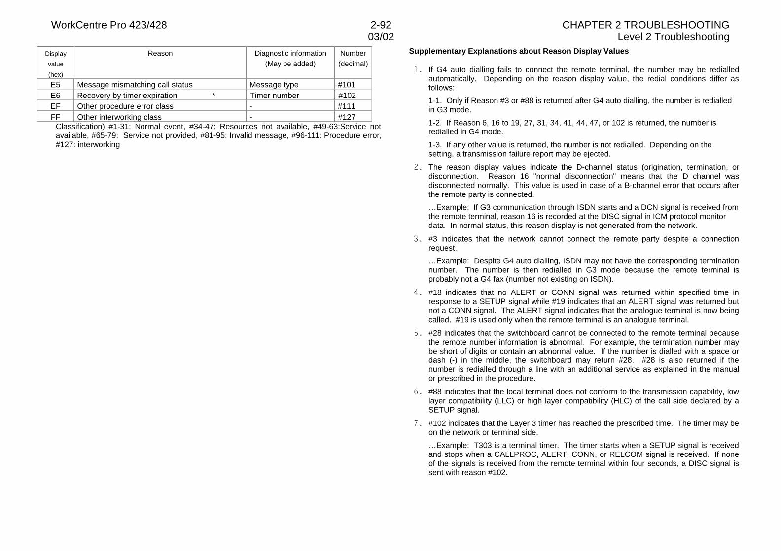
WorkCentre Pro 423/428 2-92 CHAPTER 2 TROUBLESHOOTING03/02 Level 2 Troubleshooting
Display
value
(hex)
Reason Diagnostic information
(May be added)
Number
(decimal)
E5 Message mismatching call status Message type #101E6 Recovery by timer expiration * Timer number #102EF Other procedure error class - #111FF Other interworking class - #127
Classification) #1-31: Normal event, #34-47: Resources not available, #49-63:Service notavailable, #65-79: Service not provided, #81-95: Invalid message, #96-111: Procedure error,#127: interworking
Supplementary Explanations about Reason Display Values
�� If G4 auto dialling fails to connect the remote terminal, the number may be redialledautomatically. Depending on the reason display value, the redial conditions differ asfollows:
1-1. Only if Reason #3 or #88 is returned after G4 auto dialling, the number is redialledin G3 mode.
1-2. If Reason 6, 16 to 19, 27, 31, 34, 41, 44, 47, or 102 is returned, the number isredialled in G4 mode.
1-3. If any other value is returned, the number is not redialled. Depending on thesetting, a transmission failure report may be ejected.
�� The reason display values indicate the D-channel status (origination, termination, ordisconnection. Reason 16 "normal disconnection" means that the D channel wasdisconnected normally. This value is used in case of a B-channel error that occurs afterthe remote party is connected.
…Example: If G3 communication through ISDN starts and a DCN signal is received fromthe remote terminal, reason 16 is recorded at the DISC signal in ICM protocol monitordata. In normal status, this reason display is not generated from the network.
�� #3 indicates that the network cannot connect the remote party despite a connectionrequest.
…Example: Despite G4 auto dialling, ISDN may not have the corresponding terminationnumber. The number is then redialled in G3 mode because the remote terminal isprobably not a G4 fax (number not existing on ISDN).
�� #18 indicates that no ALERT or CONN signal was returned within specified time inresponse to a SETUP signal while #19 indicates that an ALERT signal was returned butnot a CONN signal. The ALERT signal indicates that the analogue terminal is now beingcalled. #19 is used only when the remote terminal is an analogue terminal.
�� #28 indicates that the switchboard cannot be connected to the remote terminal becausethe remote number information is abnormal. For example, the termination number maybe short of digits or contain an abnormal value. If the number is dialled with a space ordash (-) in the middle, the switchboard may return #28. #28 is also returned if thenumber is redialled through a line with an additional service as explained in the manualor prescribed in the procedure.
�� #88 indicates that the local terminal does not conform to the transmission capability, lowlayer compatibility (LLC) or high layer compatibility (HLC) of the call side declared by aSETUP signal.
�� #102 indicates that the Layer 3 timer has reached the prescribed time. The timer may beon the network or terminal side.
…Example: T303 is a terminal timer. The timer starts when a SETUP signal is receivedand stops when a CALLPROC, ALERT, CONN, or RELCOM signal is received. If noneof the signals is received from the remote terminal within four seconds, a DISC signal issent with reason #102.
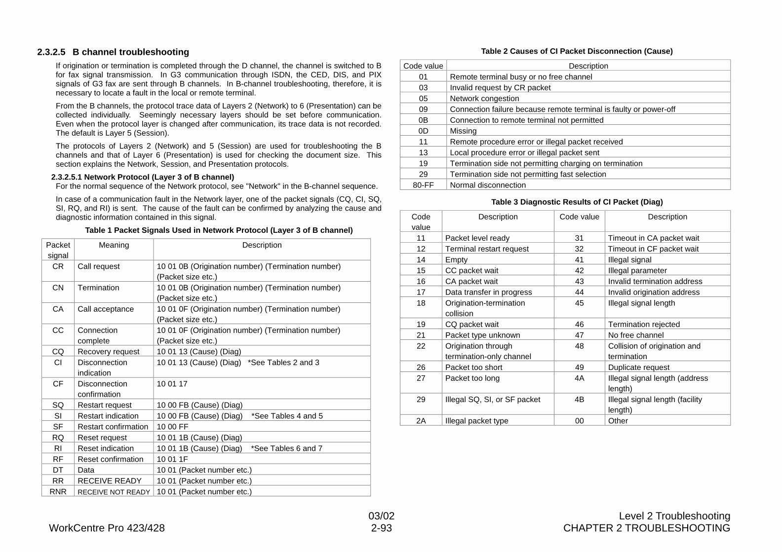
03/02 Level 2 TroubleshootingWorkCentre Pro 423/428 2-93 CHAPTER 2 TROUBLESHOOTING
2.3.2.5 B channel troubleshootingIf origination or termination is completed through the D channel, the channel is switched to Bfor fax signal transmission. In G3 communication through ISDN, the CED, DIS, and PIXsignals of G3 fax are sent through B channels. In B-channel troubleshooting, therefore, it isnecessary to locate a fault in the local or remote terminal.
From the B channels, the protocol trace data of Layers 2 (Network) to 6 (Presentation) can becollected individually. Seemingly necessary layers should be set before communication.Even when the protocol layer is changed after communication, its trace data is not recorded.The default is Layer 5 (Session).
The protocols of Layers 2 (Network) and 5 (Session) are used for troubleshooting the Bchannels and that of Layer 6 (Presentation) is used for checking the document size. Thissection explains the Network, Session, and Presentation protocols.
2.3.2.5.1 Network Protocol (Layer 3 of B channel)For the normal sequence of the Network protocol, see "Network" in the B-channel sequence.
In case of a communication fault in the Network layer, one of the packet signals (CQ, CI, SQ,SI, RQ, and RI) is sent. The cause of the fault can be confirmed by analyzing the cause anddiagnostic information contained in this signal.
Table 1 Packet Signals Used in Network Protocol (Layer 3 of B channel)
Packetsignal
Meaning Description
CR Call request 10 01 0B (Origination number) (Termination number)(Packet size etc.)
CN Termination 10 01 0B (Origination number) (Termination number)(Packet size etc.)
CA Call acceptance 10 01 0F (Origination number) (Termination number)(Packet size etc.)
CC Connectioncomplete
10 01 0F (Origination number) (Termination number)(Packet size etc.)
CQ Recovery request 10 01 13 (Cause) (Diag)CI Disconnection
indication10 01 13 (Cause) (Diag) *See Tables 2 and 3
CF Disconnectionconfirmation
10 01 17
SQ Restart request 10 00 FB (Cause) (Diag)SI Restart indication 10 00 FB (Cause) (Diag) *See Tables 4 and 5SF Restart confirmation 10 00 FFRQ Reset request 10 01 1B (Cause) (Diag)RI Reset indication 10 01 1B (Cause) (Diag) *See Tables 6 and 7RF Reset confirmation 10 01 1FDT Data 10 01 (Packet number etc.)RR RECEIVE READY 10 01 (Packet number etc.)
RNR RECEIVE NOT READY 10 01 (Packet number etc.)
Table 2 Causes of CI Packet Disconnection (Cause)
Code value Description01 Remote terminal busy or no free channel03 Invalid request by CR packet05 Network congestion09 Connection failure because remote terminal is faulty or power-off0B Connection to remote terminal not permitted0D Missing11 Remote procedure error or illegal packet received13 Local procedure error or illegal packet sent19 Termination side not permitting charging on termination29 Termination side not permitting fast selection
80-FF Normal disconnection
Table 3 Diagnostic Results of CI Packet (Diag)
Codevalue
Description Code value Description
11 Packet level ready 31 Timeout in CA packet wait12 Terminal restart request 32 Timeout in CF packet wait14 Empty 41 Illegal signal15 CC packet wait 42 Illegal parameter16 CA packet wait 43 Invalid termination address17 Data transfer in progress 44 Invalid origination address18 Origination-termination
collision45 Illegal signal length
19 CQ packet wait 46 Termination rejected21 Packet type unknown 47 No free channel22 Origination through
termination-only channel48 Collision of origination and
termination26 Packet too short 49 Duplicate request27 Packet too long 4A Illegal signal length (address
length)29 Illegal SQ, SI, or SF packet 4B Illegal signal length (facility
length)2A Illegal packet type 00 Other
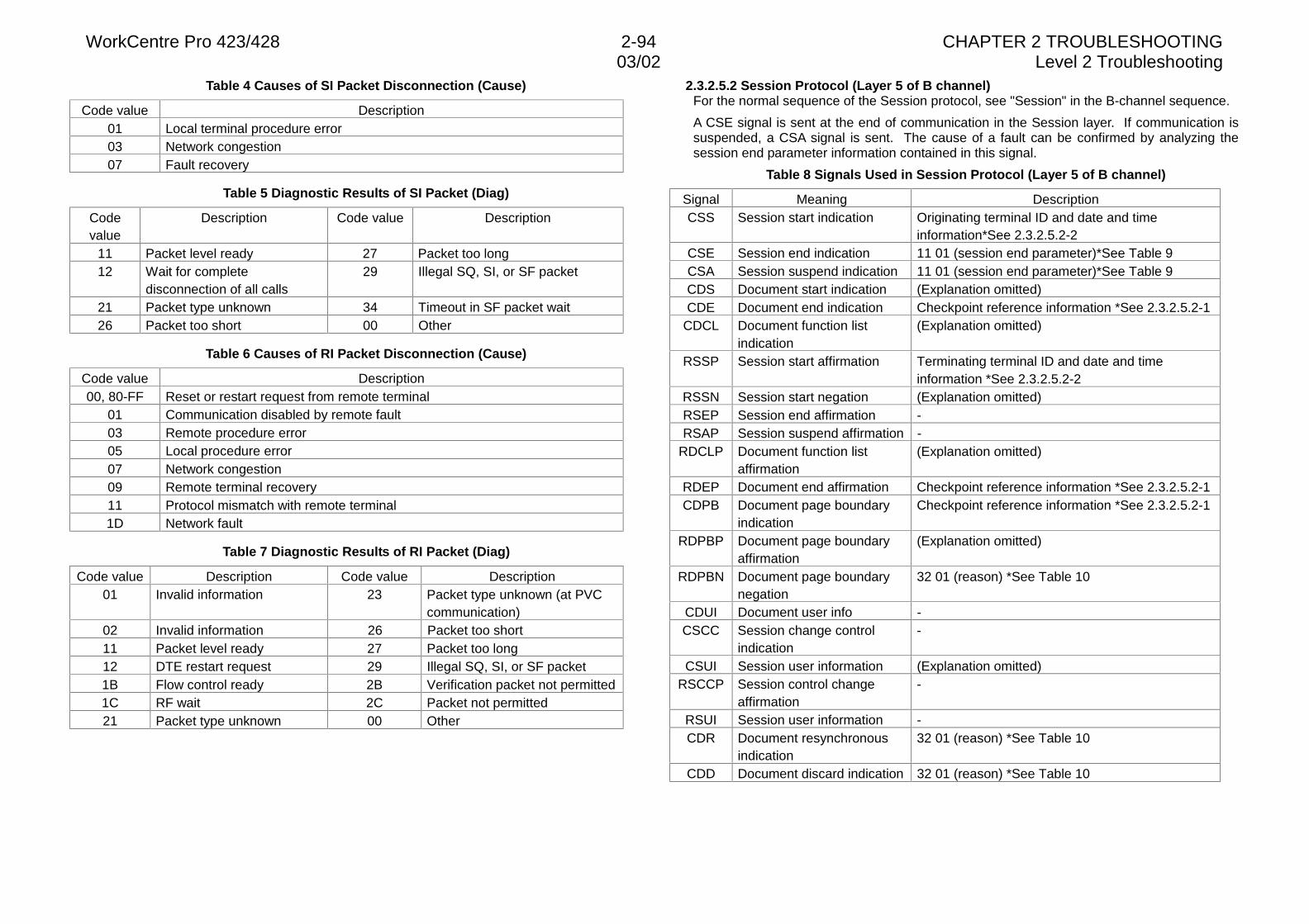
WorkCentre Pro 423/428 2-94 CHAPTER 2 TROUBLESHOOTING03/02 Level 2 Troubleshooting
Table 4 Causes of SI Packet Disconnection (Cause)
Code value Description01 Local terminal procedure error03 Network congestion07 Fault recovery
Table 5 Diagnostic Results of SI Packet (Diag)
Codevalue
Description Code value Description
11 Packet level ready 27 Packet too long12 Wait for complete
disconnection of all calls29 Illegal SQ, SI, or SF packet
21 Packet type unknown 34 Timeout in SF packet wait26 Packet too short 00 Other
Table 6 Causes of RI Packet Disconnection (Cause)
Code value Description00, 80-FF Reset or restart request from remote terminal
01 Communication disabled by remote fault03 Remote procedure error05 Local procedure error07 Network congestion09 Remote terminal recovery11 Protocol mismatch with remote terminal1D Network fault
Table 7 Diagnostic Results of RI Packet (Diag)
Code value Description Code value Description01 Invalid information 23 Packet type unknown (at PVC
communication)02 Invalid information 26 Packet too short11 Packet level ready 27 Packet too long12 DTE restart request 29 Illegal SQ, SI, or SF packet1B Flow control ready 2B Verification packet not permitted1C RF wait 2C Packet not permitted21 Packet type unknown 00 Other
2.3.2.5.2 Session Protocol (Layer 5 of B channel)For the normal sequence of the Session protocol, see "Session" in the B-channel sequence.
A CSE signal is sent at the end of communication in the Session layer. If communication issuspended, a CSA signal is sent. The cause of a fault can be confirmed by analyzing thesession end parameter information contained in this signal.
Table 8 Signals Used in Session Protocol (Layer 5 of B channel)
Signal Meaning DescriptionCSS Session start indication Originating terminal ID and date and time
information*See 2.3.2.5.2-2CSE Session end indication 11 01 (session end parameter)*See Table 9CSA Session suspend indication 11 01 (session end parameter)*See Table 9CDS Document start indication (Explanation omitted)CDE Document end indication Checkpoint reference information *See 2.3.2.5.2-1
CDCL Document function listindication
(Explanation omitted)
RSSP Session start affirmation Terminating terminal ID and date and timeinformation *See 2.3.2.5.2-2
RSSN Session start negation (Explanation omitted)RSEP Session end affirmation -RSAP Session suspend affirmation -
RDCLP Document function listaffirmation
(Explanation omitted)
RDEP Document end affirmation Checkpoint reference information *See 2.3.2.5.2-1CDPB Document page boundary
indicationCheckpoint reference information *See 2.3.2.5.2-1
RDPBP Document page boundaryaffirmation
(Explanation omitted)
RDPBN Document page boundarynegation
32 01 (reason) *See Table 10
CDUI Document user info -CSCC Session change control
indication-
CSUI Session user information (Explanation omitted)RSCCP Session control change
affirmation-
RSUI Session user information -CDR Document resynchronous
indication32 01 (reason) *See Table 10
CDD Document discard indication 32 01 (reason) *See Table 10
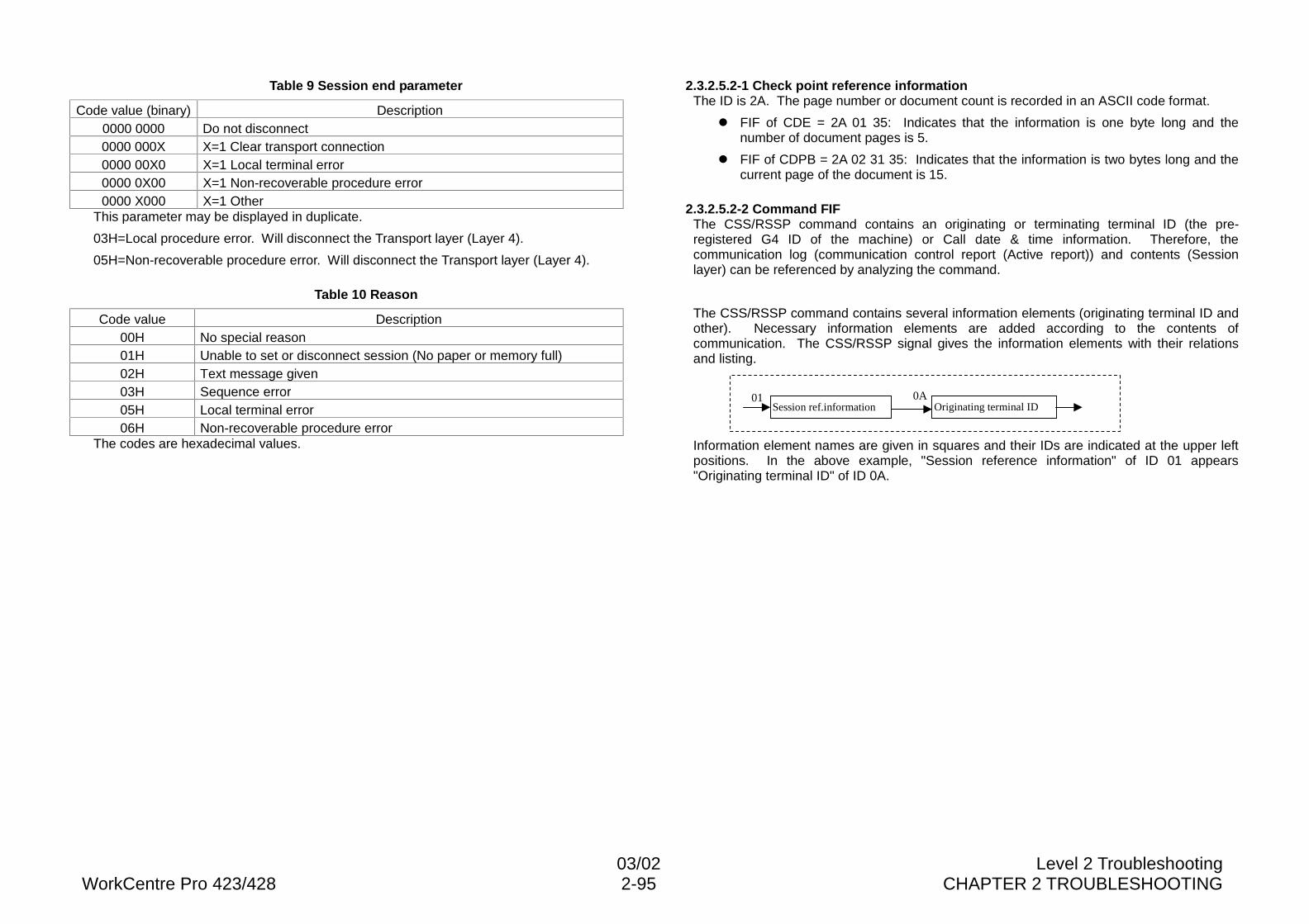
03/02 Level 2 TroubleshootingWorkCentre Pro 423/428 2-95 CHAPTER 2 TROUBLESHOOTING
Table 9 Session end parameter
Code value (binary) Description0000 0000 Do not disconnect0000 000X X=1 Clear transport connection0000 00X0 X=1 Local terminal error0000 0X00 X=1 Non-recoverable procedure error0000 X000 X=1 Other
This parameter may be displayed in duplicate.
03H=Local procedure error. Will disconnect the Transport layer (Layer 4).
05H=Non-recoverable procedure error. Will disconnect the Transport layer (Layer 4).
Table 10 Reason
Code value Description00H No special reason01H Unable to set or disconnect session (No paper or memory full)02H Text message given03H Sequence error05H Local terminal error06H Non-recoverable procedure error
The codes are hexadecimal values.
2.3.2.5.2-1 Check point reference informationThe ID is 2A. The page number or document count is recorded in an ASCII code format.
l FIF of CDE = 2A 01 35: Indicates that the information is one byte long and thenumber of document pages is 5.
l FIF of CDPB = 2A 02 31 35: Indicates that the information is two bytes long and thecurrent page of the document is 15.
2.3.2.5.2-2 Command FIFThe CSS/RSSP command contains an originating or terminating terminal ID (the pre-registered G4 ID of the machine) or Call date & time information. Therefore, thecommunication log (communication control report (Active report)) and contents (Sessionlayer) can be referenced by analyzing the command.
The CSS/RSSP command contains several information elements (originating terminal ID andother). Necessary information elements are added according to the contents ofcommunication. The CSS/RSSP signal gives the information elements with their relationsand listing.
Information element names are given in squares and their IDs are indicated at the upper leftpositions. In the above example, "Session reference information" of ID 01 appears"Originating terminal ID" of ID 0A.
01Session ref.information
0AOriginating terminal ID
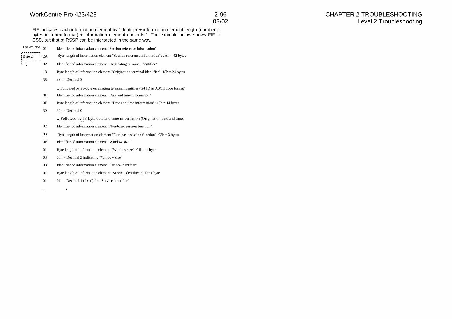
WorkCentre Pro 423/428 2-96 CHAPTER 2 TROUBLESHOOTING03/02 Level 2 Troubleshooting
FIF indicates each information element by "identifier + information element length (number ofbytes in a hex format) + information element contents." The example below shows FIF ofCSS, but that of RSSP can be interpreted in the same way.
The ex. does not contain the identifier "Additional number for session reference" or "Session function."01
2A
0A
18
38
0B
0E
30
02
03
0E
01
03
08
01
01
Identifier of information element "Session reference information"
Byte length of information element "Session reference information": 2Ah = 42 bytes
Identifier of information element "Originating terminal identifier"
Byte length of information element "Originating terminal identifier": 18h = 24 bytes
38h = Decimal 8
…Followed by 23-byte originating terminal identifier (G4 ID in ASCII code format)
Identifier of information element "Date and time information"
Byte length of information element "Date and time information": 18h = 14 bytes
30h = Decimal 0
…Followed by 13-byte date and time information (Origination date and time:YYYYMMDDhh )Identifier of information element "Non-basic session function"
Byte length of information element "Non-basic session function": 03h = 3 bytes
Identifier of information element "Window size"
Byte length of information element "Window size": 01h = 1 byte
03h = Decimal 3 indicating "Window size"
Identifier of information element "Service identifier"
Byte length of information element "Service identifier": 01h=1 byte
01h = Decimal 1 (fixed) for "Service identifier"
:
Byte 1
Byte 2
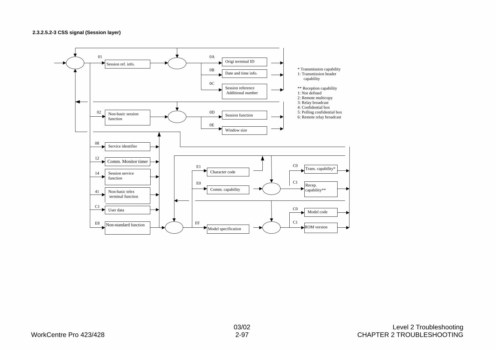
03/02 Level 2 TroubleshootingWorkCentre Pro 423/428 2-97 CHAPTER 2 TROUBLESHOOTING
2.3.2.5.2-3 CSS signal (Session layer)
01
Session ref. info.
0AOrigi terminal ID
0BDate and time info.
0CSession reference Additional number
0EWindow size
0DSession function
02 Non-basic sessionfunction
12Comm. Monitor timer
14 Session servicefunction
41 Non-basic telex terminal function
C1User data
E8 Non-standard function
08Service identifier
C1ROM version
FFModel specification
E1
Comm. capability
E0
Character code
C0Trans. capability*
C1Recep.capability**
Model codeC0
* Transmission capability1: Transmission header
capability
** Reception capability1: Not defined2: Remote multicopy3: Relay broadcast4: Confidential box5: Polling confidential box6: Remote relay broadcast
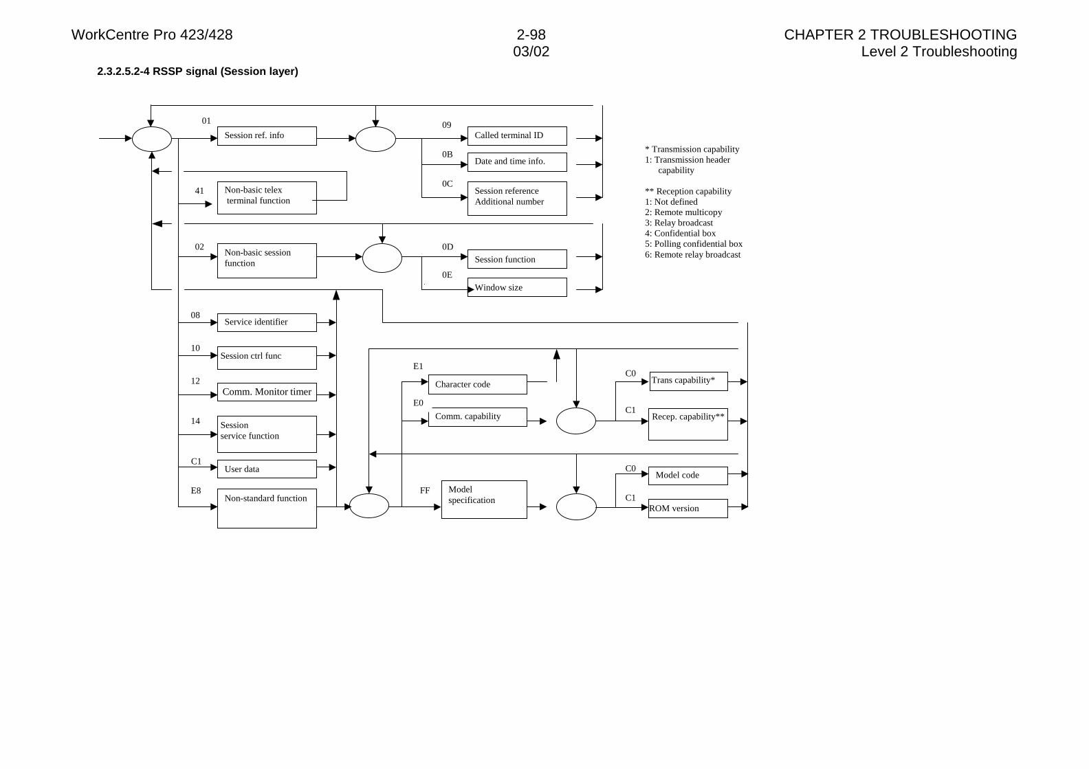
WorkCentre Pro 423/428 2-98 CHAPTER 2 TROUBLESHOOTING03/02 Level 2 Troubleshooting
2.3.2.5.2-4 RSSP signal (Session layer)
41
01
Session ref. info09
Called terminal ID
0BDate and time info.
0CSession referenceAdditional number
0EWindow size
0DSession function
02Non-basic sessionfunction
10Session ctrl func
12
14
C1User data
E8Non-standard function
08Service identifier
C1ROM version
FF Modelspecification
E1
Comm. capability
E0
Character codeC0
Trans capability*
C1Recep. capability**
Model codeC0
* Transmission capability1: Transmission header
capability
** Reception capability1: Not defined2: Remote multicopy3: Relay broadcast4: Confidential box5: Polling confidential box6: Remote relay broadcast
Non-basic telex terminal function
Sessionservice function
Comm. Monitor timer
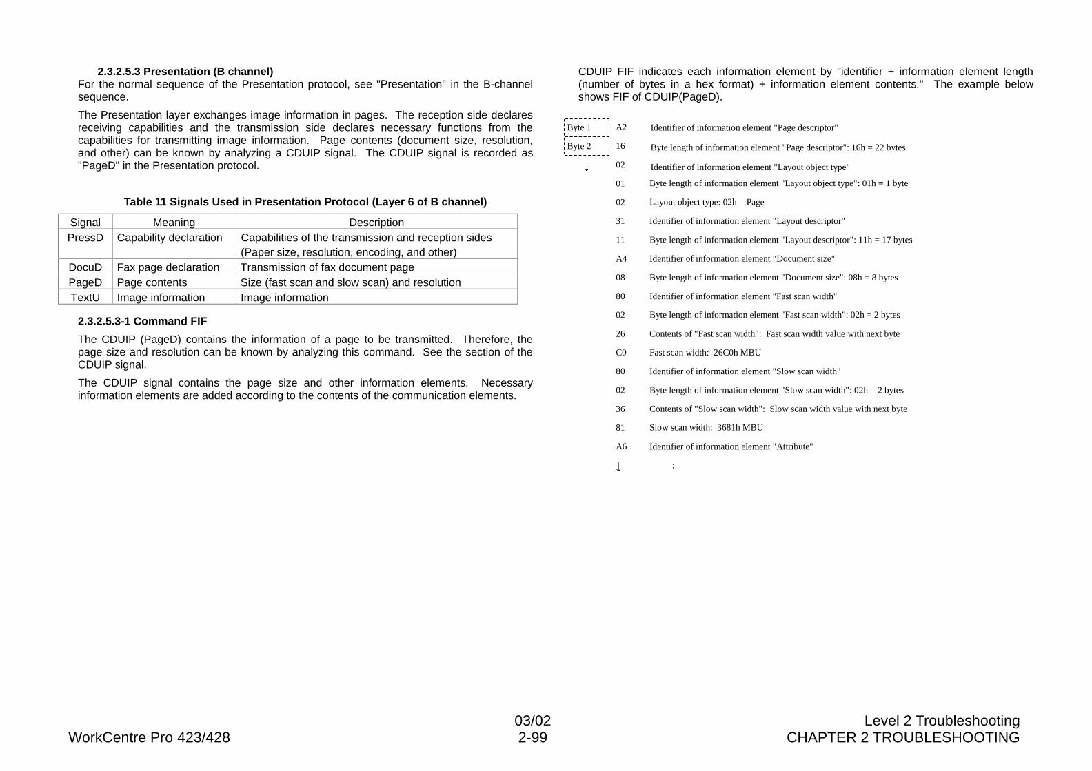
03/02 Level 2 TroubleshootingWorkCentre Pro 423/428 2-99 CHAPTER 2 TROUBLESHOOTING
2.3.2.5.3 Presentation (B channel)For the normal sequence of the Presentation protocol, see "Presentation" in the B-channelsequence.
The Presentation layer exchanges image information in pages. The reception side declaresreceiving capabilities and the transmission side declares necessary functions from thecapabilities for transmitting image information. Page contents (document size, resolution,and other) can be known by analyzing a CDUIP signal. The CDUIP signal is recorded as"PageD" in the Presentation protocol.
Table 11 Signals Used in Presentation Protocol (Layer 6 of B channel)
Signal Meaning DescriptionPressD Capability declaration Capabilities of the transmission and reception sides
(Paper size, resolution, encoding, and other)DocuD Fax page declaration Transmission of fax document pagePageD Page contents Size (fast scan and slow scan) and resolutionTextU Image information Image information
2.3.2.5.3-1 Command FIF
The CDUIP (PageD) contains the information of a page to be transmitted. Therefore, thepage size and resolution can be known by analyzing this command. See the section of theCDUIP signal.
The CDUIP signal contains the page size and other information elements. Necessaryinformation elements are added according to the contents of the communication elements.
CDUIP FIF indicates each information element by "identifier + information element length(number of bytes in a hex format) + information element contents." The example belowshows FIF of CDUIP(PageD).
A2
16
02
01
02
31
11
A4
08
80
02
26
C0
80
02
36
81
A6
Identifier of information element "Page descriptor"
Byte length of information element "Page descriptor": 16h = 22 bytes
Identifier of information element "Layout object type"
Byte length of information element "Layout object type": 01h = 1 byte
Layout object type: 02h = Page
Identifier of information element "Layout descriptor"
Byte length of information element "Layout descriptor": 11h = 17 bytes
Identifier of information element "Document size"
Byte length of information element "Document size": 08h = 8 bytes
Identifier of information element "Fast scan width"
Byte length of information element "Fast scan width": 02h = 2 bytes
Contents of "Fast scan width": Fast scan width value with next byte
Fast scan width: 26C0h MBU
Identifier of information element "Slow scan width"
Byte length of information element "Slow scan width": 02h = 2 bytes
Contents of "Slow scan width": Slow scan width value with next byte
Slow scan width: 3681h MBU
Identifier of information element "Attribute"
:
Byte 1
Byte 2
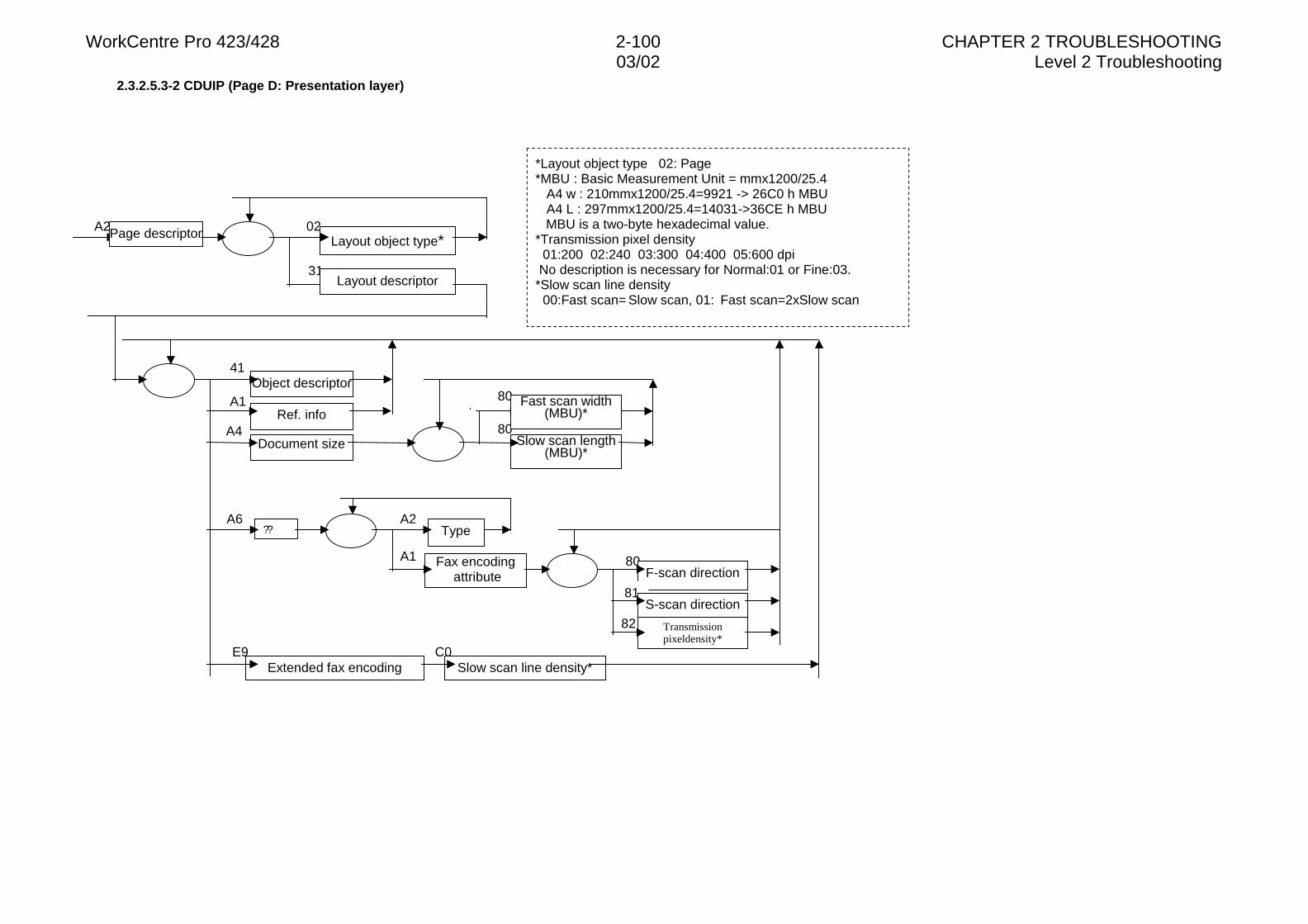
WorkCentre Pro 423/428 2-100 CHAPTER 2 TROUBLESHOOTING03/02 Level 2 Troubleshooting
2.3.2.5.3-2 CDUIP (Page D: Presentation layer)
80
82
41
A1
A4
80
A2 02
31
Ref. info
Document size
A6 A2Type
A1 80F-scan direction
81S-scan direction
Transmissionpixeldensity*
E9 C0Slow scan line density*
*Layout object type 02: Page*MBU : Basic Measurement Unit = mmx1200/25.4 A4 w : 210mmx1200/25.4=9921 -> 26C0 h MBU A4 L : 297mmx1200/25.4=14031->36CE h MBU
MBU is a two-byte hexadecimal value.*Transmission pixel density 01:200 02:240 03:300 04:400 05:600 dpi No description is necessary for Normal:01 or Fine:03.*Slow scan line density 00:Fast scan= Slow scan, 01: Fast scan=2xSlow scan
Page descriptor
Layout descriptor
Layout object type*
Object descriptor
Slow scan length(MBU)*
Fax encoding attribute
Extended fax encoding
??
Fast scan width(MBU)*
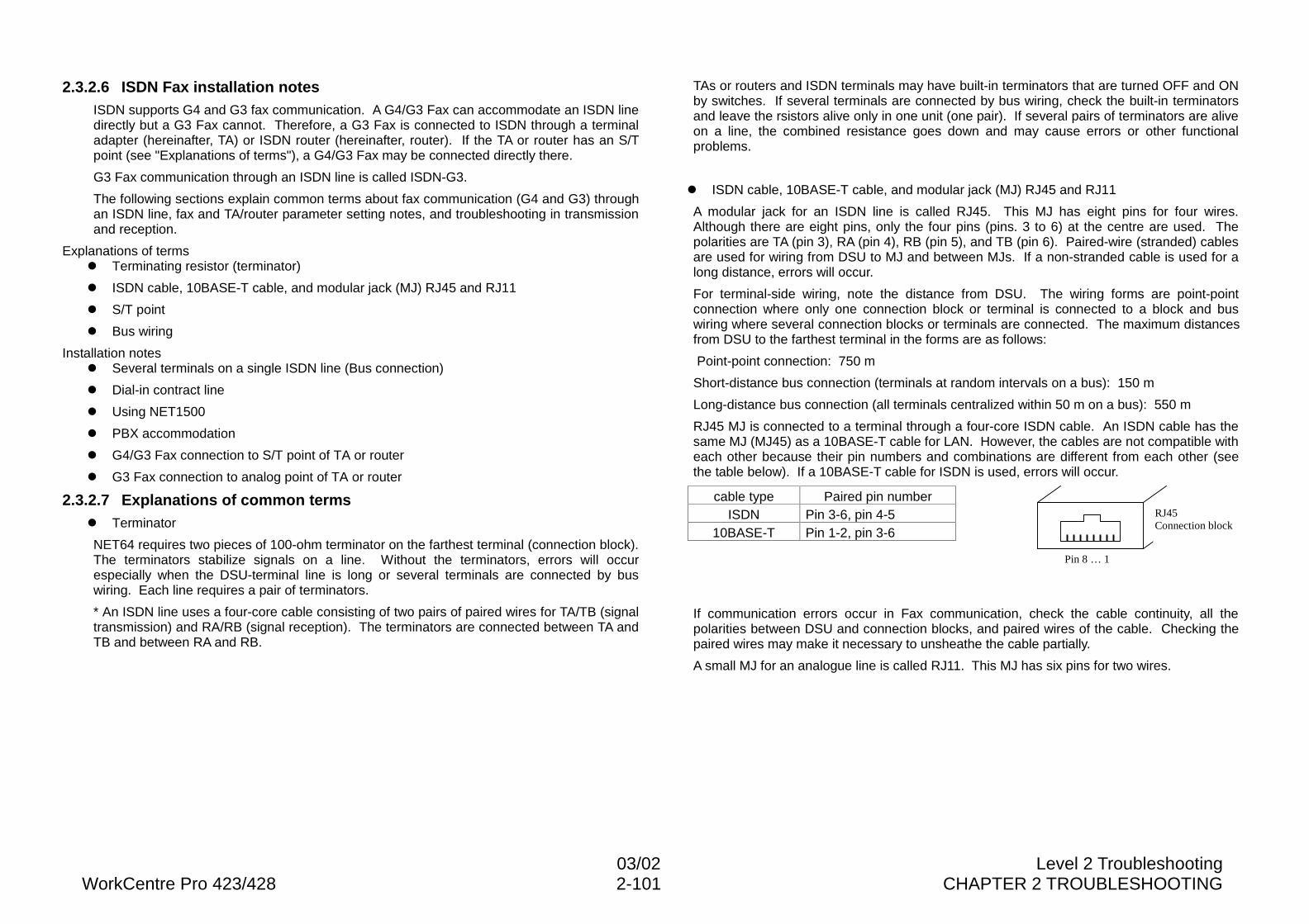
03/02 Level 2 TroubleshootingWorkCentre Pro 423/428 2-101 CHAPTER 2 TROUBLESHOOTING
2.3.2.6 ISDN Fax installation notesISDN supports G4 and G3 fax communication. A G4/G3 Fax can accommodate an ISDN linedirectly but a G3 Fax cannot. Therefore, a G3 Fax is connected to ISDN through a terminaladapter (hereinafter, TA) or ISDN router (hereinafter, router). If the TA or router has an S/Tpoint (see "Explanations of terms"), a G4/G3 Fax may be connected directly there.
G3 Fax communication through an ISDN line is called ISDN-G3.
The following sections explain common terms about fax communication (G4 and G3) throughan ISDN line, fax and TA/router parameter setting notes, and troubleshooting in transmissionand reception.
Explanations of termsl Terminating resistor (terminator)
l ISDN cable, 10BASE-T cable, and modular jack (MJ) RJ45 and RJ11
l S/T point
l Bus wiring
Installation notesl Several terminals on a single ISDN line (Bus connection)
l Dial-in contract line
l Using NET1500
l PBX accommodation
l G4/G3 Fax connection to S/T point of TA or router
l G3 Fax connection to analog point of TA or router
2.3.2.7 Explanations of common termsl Terminator
NET64 requires two pieces of 100-ohm terminator on the farthest terminal (connection block).The terminators stabilize signals on a line. Without the terminators, errors will occurespecially when the DSU-terminal line is long or several terminals are connected by buswiring. Each line requires a pair of terminators.
* An ISDN line uses a four-core cable consisting of two pairs of paired wires for TA/TB (signaltransmission) and RA/RB (signal reception). The terminators are connected between TA andTB and between RA and RB.
TAs or routers and ISDN terminals may have built-in terminators that are turned OFF and ONby switches. If several terminals are connected by bus wiring, check the built-in terminatorsand leave the rsistors alive only in one unit (one pair). If several pairs of terminators are aliveon a line, the combined resistance goes down and may cause errors or other functionalproblems.
l ISDN cable, 10BASE-T cable, and modular jack (MJ) RJ45 and RJ11
A modular jack for an ISDN line is called RJ45. This MJ has eight pins for four wires.Although there are eight pins, only the four pins (pins. 3 to 6) at the centre are used. Thepolarities are TA (pin 3), RA (pin 4), RB (pin 5), and TB (pin 6). Paired-wire (stranded) cablesare used for wiring from DSU to MJ and between MJs. If a non-stranded cable is used for along distance, errors will occur.
For terminal-side wiring, note the distance from DSU. The wiring forms are point-pointconnection where only one connection block or terminal is connected to a block and buswiring where several connection blocks or terminals are connected. The maximum distancesfrom DSU to the farthest terminal in the forms are as follows:
Point-point connection: 750 m
Short-distance bus connection (terminals at random intervals on a bus): 150 m
Long-distance bus connection (all terminals centralized within 50 m on a bus): 550 m
RJ45 MJ is connected to a terminal through a four-core ISDN cable. An ISDN cable has thesame MJ (MJ45) as a 10BASE-T cable for LAN. However, the cables are not compatible witheach other because their pin numbers and combinations are different from each other (seethe table below). If a 10BASE-T cable for ISDN is used, errors will occur.
cable type Paired pin numberISDN Pin 3-6, pin 4-5
10BASE-T Pin 1-2, pin 3-6
If communication errors occur in Fax communication, check the cable continuity, all thepolarities between DSU and connection blocks, and paired wires of the cable. Checking thepaired wires may make it necessary to unsheathe the cable partially.
A small MJ for an analogue line is called RJ11. This MJ has six pins for two wires.
Pin 8 … 16
RJ45Connection block
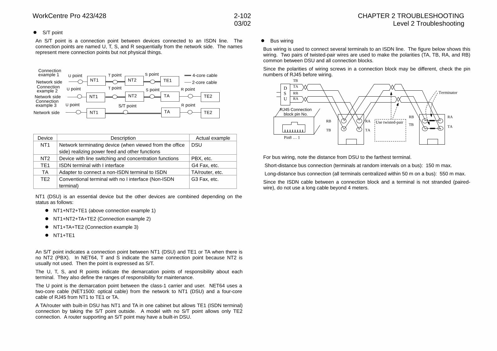
WorkCentre Pro 423/428 2-102 CHAPTER 2 TROUBLESHOOTING03/02 Level 2 Troubleshooting
l S/T point
An S/T point is a connection point between devices connected to an ISDN line. Theconnection points are named U, T, S, and R sequentially from the network side. The namesrepresent mere connection points but not physical things.
Device Description Actual exampleNT1 Network terminating device (when viewed from the office
side) realizing power feed and other functionsDSU
NT2 Device with line switching and concentration functions PBX, etc.TE1 ISDN terminal with I interface G4 Fax, etc.TA Adapter to connect a non-ISDN terminal to ISDN TA/router, etc.TE2 Conventional terminal with no I interface (Non-ISDN
terminal)G3 Fax, etc.
NT1 (DSU) is an essential device but the other devices are combined depending on thestatus as follows:
l NT1+NT2+TE1 (above connection example 1)
l NT1+NT2+TA+TE2 (Connection example 2)
l NT1+TA+TE2 (Connection example 3)
l NT1+TE1
An S/T point indicates a connection point between NT1 (DSU) and TE1 or TA when there isno NT2 (PBX). In NET64, T and S indicate the same connection point because NT2 isusually not used. Then the point is expressed as S/T.
The U, T, S, and R points indicate the demarcation points of responsibility about eachterminal. They also define the ranges of responsibility for maintenance.
The U point is the demarcation point between the class-1 carrier and user. NET64 uses atwo-core cable (NET1500: optical cable) from the network to NT1 (DSU) and a four-corecable of RJ45 from NT1 to TE1 or TA.
A TA/router with built-in DSU has NT1 and TA in one cabinet but allows TE1 (ISDN terminal)connection by taking the S/T point outside. A model with no S/T point allows only TE2connection. A router supporting an S/T point may have a built-in DSU.
l Bus wiring
Bus wiring is used to connect several terminals to an ISDN line. The figure below shows thiswiring. Two pairs of twisted-pair wires are used to make the polarities (TA, TB, RA, and RB)common between DSU and all connection blocks.
Since the polarities of wiring screws in a connection block may be different, check the pinnumbers of RJ45 before wiring.
For bus wiring, note the distance from DSU to the farthest terminal.
Short-distance bus connection (terminals at random intervals on a bus): 150 m max.
Long-distance bus connection (all terminals centralized within 50 m on a bus): 550 m max.
Since the ISDN cable between a connection block and a terminal is not stranded (paired-wire), do not use a long cable beyond 4 meters.
RA
RB
TA
TB
RB
TB
RATB
RB RA
TATA
RJ45 Connectionblock pin No.
DSU
Use twisted-pair
Pin8 … 16
Terminator
Connectionexample 1 U point
NT1 NT2 TE1
NT1 NT2 TA TE2
NT1 TA TE2
S/T point
Network side
4-core cableT point S point
R pointConnectionexample 2
Network side
T point S point
Connectionexample 3
Network side
R point
U point
U point
2-core cable
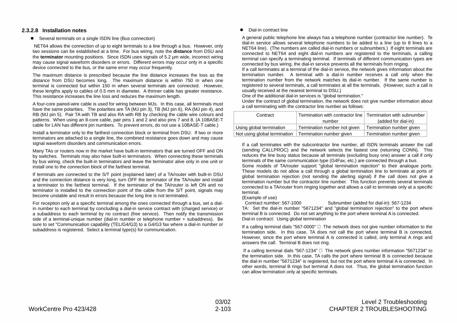
03/02 Level 2 TroubleshootingWorkCentre Pro 423/428 2-103 CHAPTER 2 TROUBLESHOOTING
2.3.2.8 Installation notesl Several terminals on a single ISDN line (Bus connection)
NET64 allows the connection of up to eight terminals to a line through a bus. However, onlytwo sessions can be established at a time. For bus wiring, note the distance from DSU andthe terminator mounting positions. Since ISDN uses signals of 5.2 µm wide, incorrect wiringmay cause signal waveform disorders or errors. Different errors may occur only in a specificdevice connected to the bus, or the same error may occur frequently.
The maximum distance is prescribed because the line distance increases the loss as thedistance from DSU becomes long. The maximum distance is within 750 m when oneterminal is connected but within 150 m when several terminals are connected. However,these lengths apply to cables of 0.5 mm in diameter. A thinner cable has greater resistance.This resistance increases the line loss and reduces the maximum length.
A four-core paired-wire cable is used for wiring between MJs. In this case, all terminals musthave the same polarities. The polarities are TA (MJ pin 3), TB (MJ pin 6), RA (MJ pin 4), andRB (MJ pin 5). Pair TA with TB and also RA with RB by checking the cable wire colours andpatterns. When using an 8-core cable, pair pins 1 and 2 and also pins 7 and 8. (A 10BASE-Tcable for LAN has different pin numbers. To prevent errors, do not use a 10BASE-T cable.)
Install a terminator only to the farthest connection block or terminal from DSU. If two or moreterminators are attached to a single line, the combined resistance goes down and may causesignal waveform disorders and communication errors.
Many TAs or routers now in the market have built-in terminators that are turned OFF and ONby switches. Terminals may also have built-in terminators. When connecting these terminalsby bus wiring, check the built-in terminators and leave the terminator alive only in one unit orinstall one to the connection block of the farthest terminal.
If terminals are connected to the S/T point (explained later) of a TA/router with built-in DSUand the connection distance is very long, turn OFF the terminator of the TA/router and installa terminator to the farthest terminal. If the terminator of the TA/router is left ON and noterminator is installed to the connection point of the cable from the S/T point, signals maybecome unstable and result in errors because the long line is not terminated.
For reception only at a specific terminal among the ones connected through a bus, set a dial-in number to each terminal by concluding a dial-in service contract with (charged service) ora subaddress to each terminal by no contract (free service). Then notify the transmissionside of a terminal-unique number (dial-in number or telephone number + subaddress). Besure to set "Communication capability (TEL/G4/G3) to a G4/G3 fax where a dial-in number orsubaddress is registered. Select a terminal type(s) for communication.
l Dial-in contract line
A general public telephone line always has a telephone number (contractor line number). Tedial-in service allows several telephone numbers to be added to a line (up to 8 lines to aNET64 line). (The numbers are called dial-in numbers or subnumbers.) If eight terminals areconnected to NET64 and eight dial-in numbers are registered to the terminals, a callingterminal can specify a terminating terminal. If terminals of different communication types areconnected by bus wiring, the dial-in service prevents all the terminals from ringing.If a call terminates at a terminal of the dial-in service, the network gives information about thetermination number. A terminal with a dial-in number receives a call only when thetermination number from the network matches its dial-in number. If the same number isregistered to several terminals, a call terminates at all the terminals. (However, such a call isusually received at the nearest terminal to DSU.)One of the additional dial-in services is "global termination."Under the contract of global termination, the network does not give number information abouta call terminating with the contractor line number as follows:
Contract Termination with contractor linenumber
Termination with subnumber(added for dial-in)
Using global termination Termination number not given Termination number givenNot using global termination Termination number given Termination number given
If a call terminates with the subcontractor line number, all ISDN terminals answer the call(sending CALLPROC) and the network selects the fastest one (returning CONN). Thisreduces the line busy status because all terminals (excluding busy one) answer a call if onlyterminals of the same communication type (G4Fax, etc.) are connected through a bus.Some models of TA/router support "global termination rejection" to their analogue ports.These models do not allow a call through a global termination line to terminate at ports ofglobal termination rejection (not sending the alerting signal) if the call does not give atermination number but the contractor line number. This function prevents several terminalsconnected to a TA/router from ringing together and allows a call to terminate only at a specificterminal.(Example of use)
Contract number: 567-1000 Subnumber (added for dial-in): 567-1234TA: Set the dial-in number "5671234" and "global termination rejection" to the port whereterminal B is connected. Do not set anything to the port where terminal A is connected.Dial-in contract: Using global termination
If a calling terminal dials "567-0000" ⇒ The network does not give number information to thetermination side. In this case, TA does not call the port where terminal B is connected.However, since the port where terminal A is connected is called, only terminal A rings andanswers the call. Terminal B does not ring.
If a calling terminal dials "567-1234" ⇒ The network gives number information "5671234" tothe termination side. In this case, TA calls the port where terminal B is connected becausethe dial-in number "5671234" is registered, but not the port where terminal A is connected. Inother words, terminal B rings but terminal A does not. Thus, the global termination functioncan allow termination only at specific terminals.
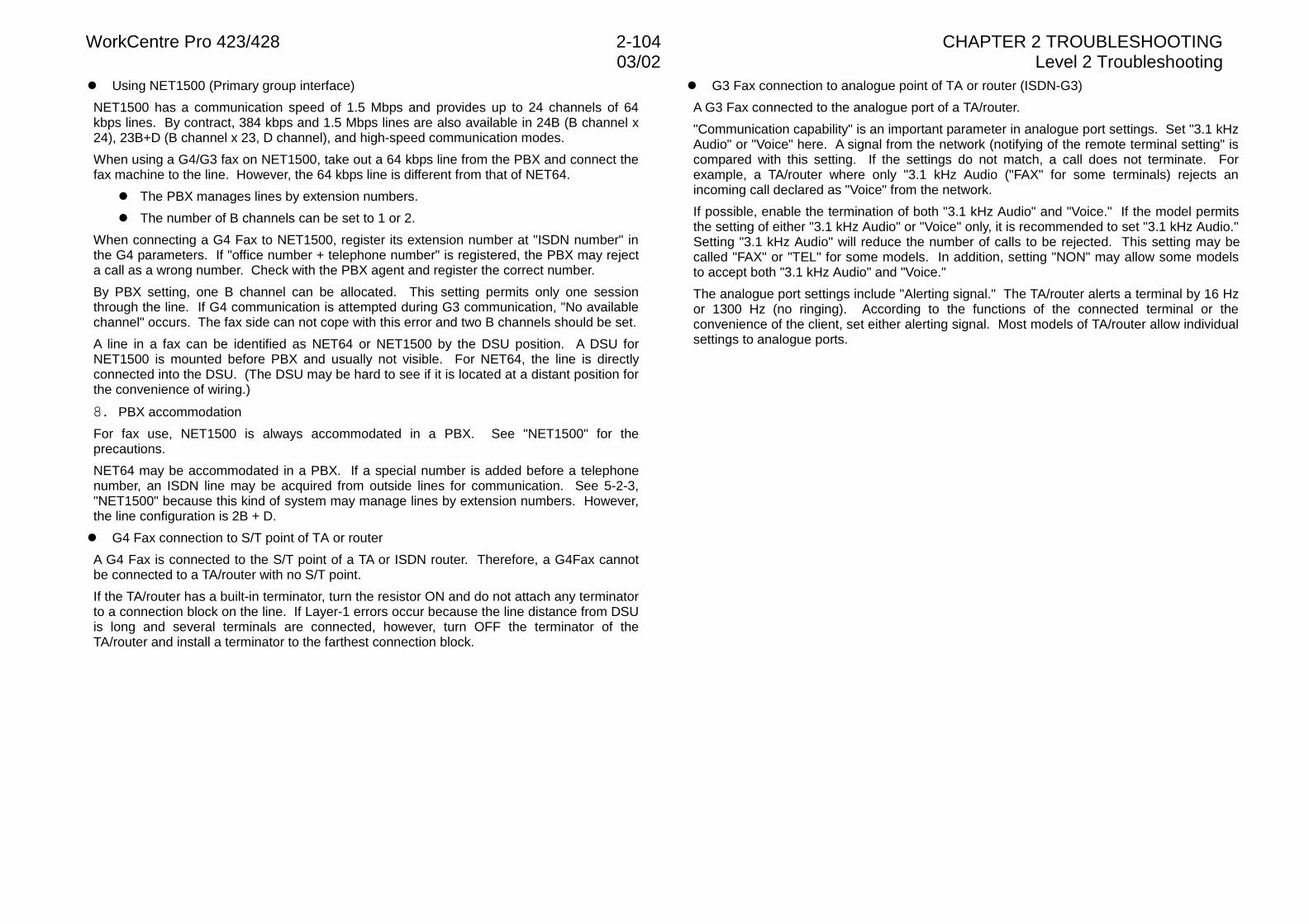
WorkCentre Pro 423/428 2-104 CHAPTER 2 TROUBLESHOOTING03/02 Level 2 Troubleshooting
l Using NET1500 (Primary group interface)
NET1500 has a communication speed of 1.5 Mbps and provides up to 24 channels of 64kbps lines. By contract, 384 kbps and 1.5 Mbps lines are also available in 24B (B channel x24), 23B+D (B channel x 23, D channel), and high-speed communication modes.
When using a G4/G3 fax on NET1500, take out a 64 kbps line from the PBX and connect thefax machine to the line. However, the 64 kbps line is different from that of NET64.
l The PBX manages lines by extension numbers.
l The number of B channels can be set to 1 or 2.
When connecting a G4 Fax to NET1500, register its extension number at "ISDN number" inthe G4 parameters. If "office number + telephone number" is registered, the PBX may rejecta call as a wrong number. Check with the PBX agent and register the correct number.
By PBX setting, one B channel can be allocated. This setting permits only one sessionthrough the line. If G4 communication is attempted during G3 communication, "No availablechannel" occurs. The fax side can not cope with this error and two B channels should be set.
A line in a fax can be identified as NET64 or NET1500 by the DSU position. A DSU forNET1500 is mounted before PBX and usually not visible. For NET64, the line is directlyconnected into the DSU. (The DSU may be hard to see if it is located at a distant position forthe convenience of wiring.)
�� PBX accommodation
For fax use, NET1500 is always accommodated in a PBX. See "NET1500" for theprecautions.
NET64 may be accommodated in a PBX. If a special number is added before a telephonenumber, an ISDN line may be acquired from outside lines for communication. See 5-2-3,"NET1500" because this kind of system may manage lines by extension numbers. However,the line configuration is 2B + D.
l G4 Fax connection to S/T point of TA or router
A G4 Fax is connected to the S/T point of a TA or ISDN router. Therefore, a G4Fax cannotbe connected to a TA/router with no S/T point.
If the TA/router has a built-in terminator, turn the resistor ON and do not attach any terminatorto a connection block on the line. If Layer-1 errors occur because the line distance from DSUis long and several terminals are connected, however, turn OFF the terminator of theTA/router and install a terminator to the farthest connection block.
l G3 Fax connection to analogue point of TA or router (ISDN-G3)
A G3 Fax connected to the analogue port of a TA/router.
"Communication capability" is an important parameter in analogue port settings. Set "3.1 kHzAudio" or "Voice" here. A signal from the network (notifying of the remote terminal setting" iscompared with this setting. If the settings do not match, a call does not terminate. Forexample, a TA/router where only "3.1 kHz Audio ("FAX" for some terminals) rejects anincoming call declared as "Voice" from the network.
If possible, enable the termination of both "3.1 kHz Audio" and "Voice." If the model permitsthe setting of either "3.1 kHz Audio" or "Voice" only, it is recommended to set "3.1 kHz Audio."Setting "3.1 kHz Audio" will reduce the number of calls to be rejected. This setting may becalled "FAX" or "TEL" for some models. In addition, setting "NON" may allow some modelsto accept both "3.1 kHz Audio" and "Voice."
The analogue port settings include "Alerting signal." The TA/router alerts a terminal by 16 Hzor 1300 Hz (no ringing). According to the functions of the connected terminal or theconvenience of the client, set either alerting signal. Most models of TA/router allow individualsettings to analogue ports.
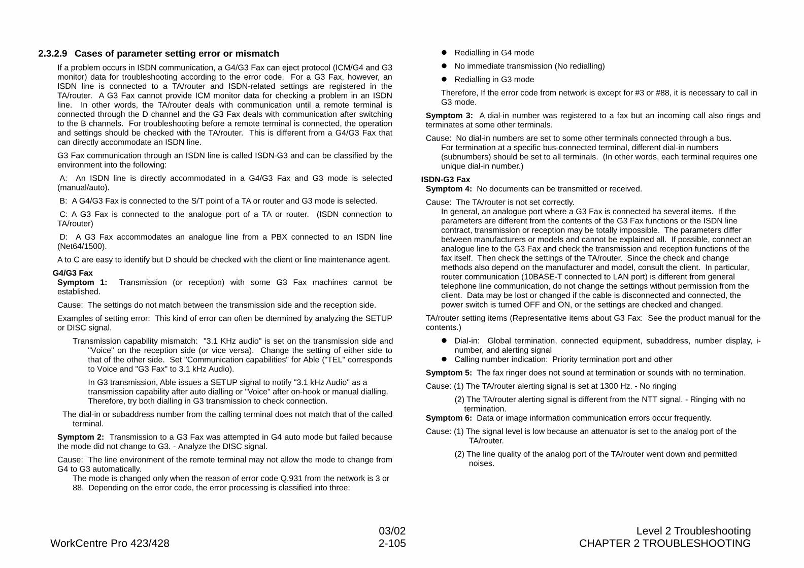
03/02 Level 2 TroubleshootingWorkCentre Pro 423/428 2-105 CHAPTER 2 TROUBLESHOOTING
2.3.2.9 Cases of parameter setting error or mismatchIf a problem occurs in ISDN communication, a G4/G3 Fax can eject protocol (ICM/G4 and G3monitor) data for troubleshooting according to the error code. For a G3 Fax, however, anISDN line is connected to a TA/router and ISDN-related settings are registered in theTA/router. A G3 Fax cannot provide ICM monitor data for checking a problem in an ISDNline. In other words, the TA/router deals with communication until a remote terminal isconnected through the D channel and the G3 Fax deals with communication after switchingto the B channels. For troubleshooting before a remote terminal is connected, the operationand settings should be checked with the TA/router. This is different from a G4/G3 Fax thatcan directly accommodate an ISDN line.
G3 Fax communication through an ISDN line is called ISDN-G3 and can be classified by theenvironment into the following:
A: An ISDN line is directly accommodated in a G4/G3 Fax and G3 mode is selected(manual/auto).
B: A G4/G3 Fax is connected to the S/T point of a TA or router and G3 mode is selected.
C: A G3 Fax is connected to the analogue port of a TA or router. (ISDN connection toTA/router)
D: A G3 Fax accommodates an analogue line from a PBX connected to an ISDN line(Net64/1500).
A to C are easy to identify but D should be checked with the client or line maintenance agent.
G4/G3 FaxSymptom 1: Transmission (or reception) with some G3 Fax machines cannot beestablished.
Cause: The settings do not match between the transmission side and the reception side.
Examples of setting error: This kind of error can often be dtermined by analyzing the SETUPor DISC signal.
Transmission capability mismatch: "3.1 KHz audio" is set on the transmission side and"Voice" on the reception side (or vice versa). Change the setting of either side tothat of the other side. Set "Communication capabilities" for Able ("TEL" correspondsto Voice and "G3 Fax" to 3.1 kHz Audio).
In G3 transmission, Able issues a SETUP signal to notify "3.1 kHz Audio" as atransmission capability after auto dialling or "Voice" after on-hook or manual dialling.Therefore, try both dialling in G3 transmission to check connection.
The dial-in or subaddress number from the calling terminal does not match that of the calledterminal.
Symptom 2: Transmission to a G3 Fax was attempted in G4 auto mode but failed becausethe mode did not change to G3. - Analyze the DISC signal.
Cause: The line environment of the remote terminal may not allow the mode to change fromG4 to G3 automatically.
The mode is changed only when the reason of error code Q.931 from the network is 3 or88. Depending on the error code, the error processing is classified into three:
l Redialling in G4 mode
l No immediate transmission (No redialling)
l Redialling in G3 mode
Therefore, If the error code from network is except for #3 or #88, it is necessary to call inG3 mode.
Symptom 3: A dial-in number was registered to a fax but an incoming call also rings andterminates at some other terminals.
Cause: No dial-in numbers are set to some other terminals connected through a bus.For termination at a specific bus-connected terminal, different dial-in numbers(subnumbers) should be set to all terminals. (In other words, each terminal requires oneunique dial-in number.)
ISDN-G3 FaxSymptom 4: No documents can be transmitted or received.
Cause: The TA/router is not set correctly.In general, an analogue port where a G3 Fax is connected ha several items. If theparameters are different from the contents of the G3 Fax functions or the ISDN linecontract, transmission or reception may be totally impossible. The parameters differbetween manufacturers or models and cannot be explained all. If possible, connect ananalogue line to the G3 Fax and check the transmission and reception functions of thefax itself. Then check the settings of the TA/router. Since the check and changemethods also depend on the manufacturer and model, consult the client. In particular,router communication (10BASE-T connected to LAN port) is different from generaltelephone line communication, do not change the settings without permission from theclient. Data may be lost or changed if the cable is disconnected and connected, thepower switch is turned OFF and ON, or the settings are checked and changed.
TA/router setting items (Representative items about G3 Fax: See the product manual for thecontents.)
l Dial-in: Global termination, connected equipment, subaddress, number display, i-number, and alerting signal
l Calling number indication: Priority termination port and other
Symptom 5: The fax ringer does not sound at termination or sounds with no termination.
Cause: (1) The TA/router alerting signal is set at 1300 Hz. - No ringing
(2) The TA/router alerting signal is different from the NTT signal. - Ringing with notermination.
Symptom 6: Data or image information communication errors occur frequently.
Cause: (1) The signal level is low because an attenuator is set to the analog port of theTA/router.
(2) The line quality of the analog port of the TA/router went down and permittednoises.
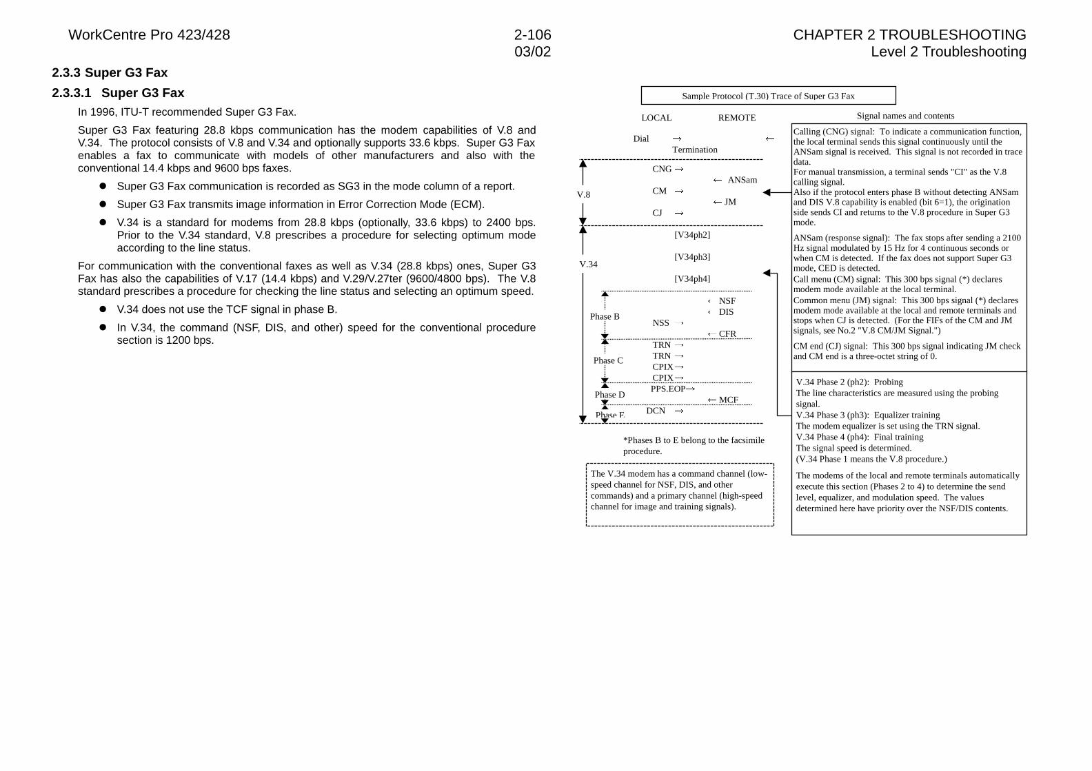
WorkCentre Pro 423/428 2-106 CHAPTER 2 TROUBLESHOOTING03/02 Level 2 Troubleshooting
2.3.3 Super G3 Fax
2.3.3.1 Super G3 FaxIn 1996, ITU-T recommended Super G3 Fax.
Super G3 Fax featuring 28.8 kbps communication has the modem capabilities of V.8 andV.34. The protocol consists of V.8 and V.34 and optionally supports 33.6 kbps. Super G3 Faxenables a fax to communicate with models of other manufacturers and also with theconventional 14.4 kbps and 9600 bps faxes.
l Super G3 Fax communication is recorded as SG3 in the mode column of a report.
l Super G3 Fax transmits image information in Error Correction Mode (ECM).
l V.34 is a standard for modems from 28.8 kbps (optionally, 33.6 kbps) to 2400 bps.Prior to the V.34 standard, V.8 prescribes a procedure for selecting optimum modeaccording to the line status.
For communication with the conventional faxes as well as V.34 (28.8 kbps) ones, Super G3Fax has also the capabilities of V.17 (14.4 kbps) and V.29/V.27ter (9600/4800 bps). The V.8standard prescribes a procedure for checking the line status and selecting an optimum speed.
l V.34 does not use the TCF signal in phase B.
l In V.34, the command (NSF, DIS, and other) speed for the conventional proceduresection is 1200 bps.
Signal names and contents
DialTermination
Calling (CNG) signal: To indicate a communication function,the local terminal sends this signal continuously until theANSam signal is received. This signal is not recorded in tracedata.For manual transmission, a terminal sends "CI" as the V.8calling signal.Also if the protocol enters phase B without detecting ANSamand DIS V.8 capability is enabled (bit 6=1), the originationside sends CI and returns to the V.8 procedure in Super G3mode.
ANSam (response signal): The fax stops after sending a 2100Hz signal modulated by 15 Hz for 4 continuous seconds orwhen CM is detected. If the fax does not support Super G3mode, CED is detected.Call menu (CM) signal: This 300 bps signal (*) declaresmodem mode available at the local terminal.Common menu (JM) signal: This 300 bps signal (*) declaresmodem mode available at the local and remote terminals andstops when CJ is detected. (For the FIFs of the CM and JMsignals, see No.2 "V.8 CM/JM Signal.")
CM end (CJ) signal: This 300 bps signal indicating JM checkand CM end is a three-octet string of 0.
[V34ph2]
[V34ph3]
[V34ph4]
V.34 Phase 2 (ph2): ProbingThe line characteristics are measured using the probingsignal.V.34 Phase 3 (ph3): Equalizer trainingThe modem equalizer is set using the TRN signal.V.34 Phase 4 (ph4): Final trainingThe signal speed is determined.(V.34 Phase 1 means the V.8 procedure.)
The modems of the local and remote terminals automaticallyexecute this section (Phases 2 to 4) to determine the sendlevel, equalizer, and modulation speed. The valuesdetermined here have priority over the NSF/DIS contents.
NSF DIS
��NSS CFR
��TRN��TRN��CPIX��CPIX
PPS.EOP MCF
DCN
LOCAL REMOTE
��CNG������� �ANSam
��CM������� JM
��CJ
V.8
V.34
Phase B
Sample Protocol (T.30) Trace of Super G3 Fax
The V.34 modem has a command channel (low-speed channel for NSF, DIS, and othercommands) and a primary channel (high-speedchannel for image and training signals).
Phase C
Phase D
*Phases B to E belong to the facsimileprocedure.
Phase E
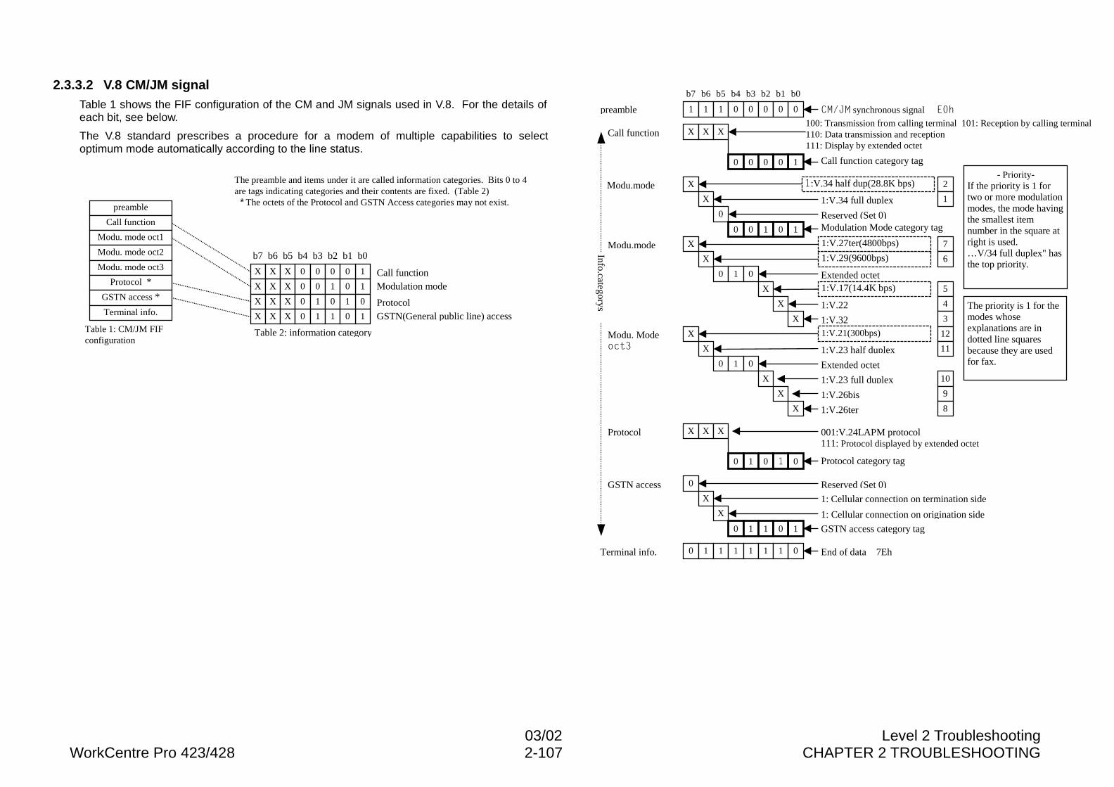
03/02 Level 2 TroubleshootingWorkCentre Pro 423/428 2-107 CHAPTER 2 TROUBLESHOOTING
2.3.3.2 V.8 CM/JM signalTable 1 shows the FIF configuration of the CM and JM signals used in V.8. For the details ofeach bit, see below.
The V.8 standard prescribes a procedure for a modem of multiple capabilities to selectoptimum mode automatically according to the line status.
Table 2: information categoryTable 1: CM/JM FIFconfiguration
preamble
Call function
Modu. mode oct1
Modu. mode oct2
Modu. mode oct3
Protocol *
GSTN access *X 1X X 0 0 1 0
X 0X X 0 1 0 1
X 1X X 0 1 1 0 GSTN(General public line) access
Call functionModulation mode
Protocol
The preamble and items under it are called information categories. Bits 0 to 4are tags indicating categories and their contents are fixed. (Table 2)
* The octets of the Protocol and GSTN Access categories may not exist.
b7 b6 b5 b4 b3 b2 b1 b0
X 1X X 0 0 0 0
Terminal info.
Modu.mode
preamble
b7 b6 b5 b4 b3 b2 b1 b0
1 01 1 0 0 0 0
Call function X X X
10 0 0 0
100: Transmission from calling terminal 101: Reception by calling terminal110: Data transmission and reception111: Display by extended octet
X
X
0
10 0 1 0
1:V.34 full duplex
Reserved (Set 0)
X
X
X
0 1 0
X
X
Extended octet
1:V.22
1:V.32X
X
X
0 1 0
X
X
1:V.23 half duplex
Extended octet
1:V.23 full duplex
1:V.26bis
1:V.26ter
- Priority-If the priority is 1 fortwo or more modulationmodes, the mode havingthe smallest itemnumber in the square atright is used.…V/34 full duplex" hasthe top priority.
X
0
X X
0 1 0 �
Protocol 001:V.24LAPM protocol111: Protocol displayed by extended octet
0
1
X
X
0 1 1 0
GSTN access Reserved (Set 0)
1: Cellular connection on termination side
1: Cellular connection on origination side
Modu.mode
Modu. ModeRFW�
Call function category tag
Modulation Mode category tag
Protocol category tag
GSTN access category tag
The priority is 1 for themodes whoseexplanations are indotted line squaresbecause they are usedfor fax.
2
1
7
6
5
4
3
12
11
10
9
8
&0�-0 synchronous signal��(�K
Info.categorys
1:V.21(300bps)
1:V.17(14.4K bps)
1:V.29(9600bps)
1:V.27ter(4800bps)
�:V.34 half dup(28.8K bps)
Terminal info. 0 01 1 1 1 1 1 End of data 7Eh
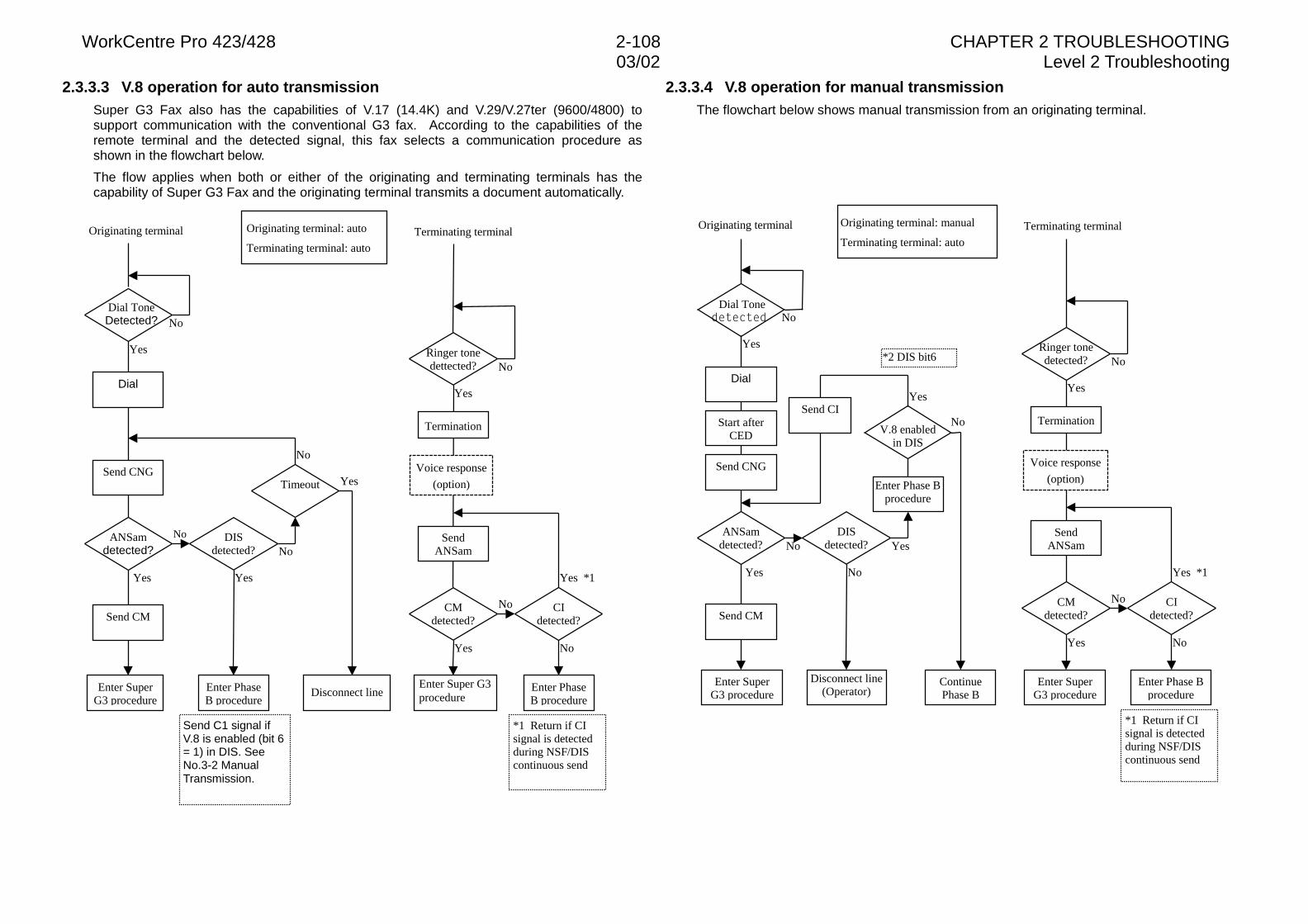
WorkCentre Pro 423/428 2-108 CHAPTER 2 TROUBLESHOOTING03/02 Level 2 Troubleshooting
2.3.3.3 V.8 operation for auto transmissionSuper G3 Fax also has the capabilities of V.17 (14.4K) and V.29/V.27ter (9600/4800) tosupport communication with the conventional G3 fax. According to the capabilities of theremote terminal and the detected signal, this fax selects a communication procedure asshown in the flowchart below.
The flow applies when both or either of the originating and terminating terminals has thecapability of Super G3 Fax and the originating terminal transmits a document automatically.
2.3.3.4 V.8 operation for manual transmissionThe flowchart below shows manual transmission from an originating terminal.
No
Yes
No
No
Yes
No
No
No
No
Yes *1
Yes
Yes
Yes
Yes
Dial ToneDetected?
ANSamdetected?
DISdetected?
Timeout
Enter SuperG3 procedure
Ringer tonedettected?
CMdetected?
CIdetected?
Enter Super G3procedure
Enter PhaseB procedure
Send CNG
Dial
SendANSam
Voice response
(option)
Termination
Originating terminal: auto
Terminating terminal: auto
Disconnect line
Send CM
Enter PhaseB procedure
*1 Return if CIsignal is detectedduring NSF/DIScontinuous send
Terminating terminalOriginating terminal
Send C1 signal ifV.8 is enabled (bit 6= 1) in DIS. SeeNo.3-2 ManualTransmission.
No
No
No
No
No
Yes *1
Yes
YesYes
Yes
Yes
No
No
Yes
Dial ToneGHWHFWHG
ANSamdetected?
DISdetected?
V.8 enabledin DIS
Enter SuperG3 procedure
Disconnect line(Operator)
Ringer tonedetected?
CMdetected?
CIdetected?
Enter SuperG3 procedure
Enter Phase Bprocedure
Send CM
Send CNG
Dial
SendANSam
Voice response
(option)
TerminationStart afterCED
Enter Phase Bprocedure
ContinuePhase B
Send CI
*1 Return if CIsignal is detectedduring NSF/DIScontinuous send
*2 DIS bit6
Originating terminal: manual
Terminating terminal: auto
Terminating terminalOriginating terminal

03/02 Level 2 TroubleshootingWorkCentre Pro 423/428 2-109 CHAPTER 2 TROUBLESHOOTING
2.3.3.5 Troubleshooting of Super G3 FaxSuper G3 fax uses analogue communication and its troubleshooting is basically the same asthat of the conventional G3 Fax. However, since the communication speed and procedure aredifferent, this section describes troubleshooting unique to Super G3 mode.
Super G3 Fax realizes communication up to 28,800 bps by a modem of the V.34 standard.The speed can be optionally increased up to 33,600 bps.
The conventional speed is 14,400 bps (V.17). To realize the high-speed communication ofV.34, the conventional data transmission rate must be more than doubled. Therefore, thetelephone line quality will affect communication more than ever. Even a telephone lineavailable for error-free communication at 14,400 or 9600 bps may cause an error in Super G3communication.
An ordinary analogue public line shows a good frequency characteristic in a band from 300 to3,400 Hz. In Super G3 communication, the communication speed may differ if only thedirection of communication is reversed without changing the parties or the telephone line. Inthis communication, the transmission side determines the communication speed according tothe result of line quality measurement by the probing function in the V.34 procedure and theprobing result varies each time the direction of communication is reversed. In other words,Super G3 mode cannot always achieve the maximum speed (33,600 bps). In most cases, theSuper G3 communication speed is 21,600 bps or more.
The conventional fax up to 14,400 bps uses half-duplex communication where signals aresent alternately. Super G3 fax, however, uses full-duplex communication of a differentcommunication procedure. In full-duplex communication, both faxes issue signals together.While sending signals, each fax monitors signals from the other fax. The communicationstatus can be supervised by monitoring a line for sounds in the conventional faxcommunication but not in Super G3 communication. If a communication error occurs, theanalysis of protocol monitor data is necessary more than ever and the trace data of both thetransmitter and receiver may be compared often.
Notes on Super G3 troubleshootingECM: ECM is essential for Super G3 communication. If the ECM function is OFF, even a faxsupporting Super G3 mode will use not V.34 but V.17/V.29 (14,000/9600 bps) forcommunication.
Communication procedure: The Super G3 communication procedure consists of V.8 andV.34. The V.8 procedure is used to check the Super G3 mode capability and to determine thecommunication speed. Once the V.8 procedure has terminated normally, Super G3 faxchanges to the V.34 procedure and sends image information by the V.34 procedure. The V.34procedure uses the same commands as the G3 procedure (V.17/V.29 or other) and theprotocol trace data is also almost the same. However, the actual communication type is fullduplex and the command transmission speed is 1200 bps.
The V.8 procedure uses the tonal signals of CNG or CI sent from an originating terminal formanual transmission and ANSam sent from a terminating terminal. If the line receives noisesor the signal level is low, an error occurs because the remote terminal cannot recognize thetonal signals correctly. For this check, protocol data of the remote terminal is checked to seewhether signals sent from the local terminal are recorded (as recorded in the local trace data).
The V.34 procedure is executed in the order of phases 2, 3, and 4 and [V34ph2], [V34ph3],and [V34ph4] are recorded in the protocol trace data. Once phase 4 has terminated normally,the procedure changes to phases B, C, D, and E. For troubleshooting in these phases,reference the conventional procedure.
If the line receives noises or the signal level is low, the procedure may not progress smoothly.If phases 2, 3, and 4 are repeated, [V34ph2], [V34ph3], and [V34ph4] are recorded again andagain in the protocol trace data. If an error occurs in phase 2, [V34ph2] is recorded but[V34ph3] and [V34ph4] are not.
In both of the above two cases, the analog characteristics of the telephone line are defectiveor the send level is inappropriate.
Send level: Since Super G3 Fax uses analog communication, the signal level is veryimportant. Especially, the signal to noise level (S/N) ratio is the key. For correct signaldetection, a certain S/N ratio is necessary. The protocol data may indicate that the remoteterminal sends the same signal repeatedly or does not advance to the next procedure. Thismeans that the remote terminal cannot recognize signals from the local terminal. In this case,change the send level. If the noise level does not change, raising the send level shouldincrease the S/N ratio. When changing the send level, vary the send level a little (1 or 2 dB)and find the best value by trying communication several times.
If a digital line (ISDN/corporate digital leased line) or digital equipment (digital PBX/TA) is inuse, raising the level too high will cause a waveform disorder to an analog signal and disablenormal communication (high-level signal waveforms are deformed at analog-digitalconversion). Under this kind of line environment, lowering the send level will establish goodcommunication.
Speed: The maximum speed is 33,600 bps in Super G3 mode. In domestic PSTNcommunication, however, the actual speed is 31,200 to 21,600 bps in most cases. If the linestatus is extremely bad, the speed may be even as low as 9600 bps. The communicationspeed is determined by a transmission terminal according to the result of phase 2 in V.34.Therefore, even when the same line is used, the communication speed varies with thetransmission terminal.
Line frequency characteristic (F characteristic): The characteristic of a telephone line aboutfrequency is called "frequency characteristic." The characteristic ideally should be uniform inthe speech band from 300 to 3400 Hz but usually deteriorated at at high and low frequenciesof a public line (attenuation distortion or signal delay not affecting a speech). The longer theground distance (more precisely, the line distance of the analogue section) becomes, theworse the deterioration becomes. Compared with ordinary voice or G3 Fax communication,Super G3 communication is greatly affected by the frequency characteristic. Even a lineavailable for normal communication at 14,000 or 9600 bps may cause errors in Super G3communication. Since most corporate leased lines (digital lines) use voice compression, theirfrequency characteristics are worse than those of NTT public lines. Therefore, the erroroccurrence rate goes high in Super G3 communication.
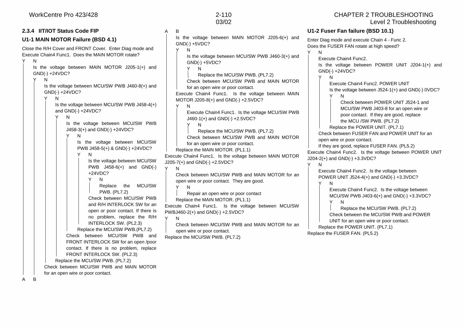
WorkCentre Pro 423/428 2-110 CHAPTER 2 TROUBLESHOOTING03/02 Level 2 Troubleshooting
2.3.4 IIT/IOT Status Code FIP
U1-1 MAIN MOTOR Failure (BSD 4.1)
Close the R/H Cover and FRONT Cover. Enter Diag mode andExecute Chain4 Func1. Does the MAIN MOTOR rotate?Y N
Is the voltage between MAIN MOTOR J205-1(+) andGND(-) +24VDC?Y N
Is the voltage between MCU/SW PWB J460-8(+) andGND(-) +24VDC?Y N
Is the voltage between MCU/SW PWB J458-4(+)and GND(-) +24VDC?Y N
Is the voltage between MCU/SW PWBJ458-3(+) and GND(-) +24VDC?Y N
Is the voltage between MCU/SWPWB J458-5(+) & GND(-) +24VDC?Y N
Is the voltage between MCU/SWPWB J458-6(+) and GND(-)+24VDC?Y N
Replace the MCU/SWPWB. (PL7.2)
Check between MCU/SW PWBand R/H INTERLOCK SW for anopen or poor contact. If there isno problem, replace the R/HINTERLOCK SW. (PL2.3)
Replace the MCU/SW PWB.(PL7.2)Check between MCU/SW PWB andFRONT INTERLOCK SW for an open /poorcontact. If there is no problem, replaceFRONT INTERLOCK SW. (PL2.3)
Replace the MCU/SW PWB. (PL7.2)Check between MCU/SW PWB and MAIN MOTORfor an open wire or poor contact.
A B
A BIs the voltage between MAIN MOTOR J205-6(+) andGND(-) +5VDC?Y N
Is the voltage between MCU/SW PWB J460-3(+) andGND(-) +5VDC?Y N
Replace the MCU/SW PWB. (PL7.2)Check between MCU/SW PWB and MAIN MOTORfor an open wire or poor contact.
Execute Chain4 Func1. Is the voltage between MAINMOTOR J205-8(+) and GND(-) +2.5VDC?Y N
Execute Chain4 Func1. Is the voltage MCU/SW PWBJ460-1(+) and GND(-) +2.5VDC?Y N
Replace the MCU/SW PWB. (PL7.2)Check between MCU/SW PWB and MAIN MOTORfor an open wire or poor contact.
Replace the MAIN MOTOR. (PL1.1)Execute Chain4 Func1. Is the voltage between MAIN MOTORJ205-7(+) and GND(-) +2.5VDC?Y N
Check between MCU/SW PWB and MAIN MOTOR for anopen wire or poor contact. They are good.Y N
Repair an open wire or poor contactReplace the MAIN MOTOR. (PL1.1)
Execute Chain4 Func1. Is the voltage between MCU/SWPWBJ460-2(+) and GND(-) +2.5VDC?Y N
Check between MCU/SW PWB and MAIN MOTOR for anopen wire or poor contact.
Replace the MCU/SW PWB. (PL7.2)
U1-2 Fuser Fan failure (BSD 10.1)
Enter Diag mode and execute Chain 4 - Func 2.Does the FUSER FAN rotate at high speed?Y N
Execute Chain4 Func2.Is the voltage between POWER UNIT J204-1(+) andGND(-) +24VDC?Y N
Execute Chain4 Func2. POWER UNITIs the voltage between J524-1(+) and GND(-) 0VDC?Y N
Check between POWER UNIT J524-1 andMCU/SW PWB J403-8 for an open wire orpoor contact. If they are good, replacethe MCU /SW PWB. (PL7.2)
Replace the POWER UNIT. (PL7.1)Check between FUSER FAN and POWER UNIT for anopen wire or poor contact.If they are good, replace FUSER FAN. (PL5.2)
Execute Chain4 Func2. Is the voltage between POWER UNITJ204-2(+) and GND(-) +3.3VDC?Y N
Execute Chain4 Func2. Is the voltage betweenPOWER UNIT J524-4(+) and GND(-) +3.3VDC?Y N
Execute Chain4 Func2. Is the voltage betweenMCU/SW PWB J403-6(+) and GND(-) +3.3VDC?Y N
Replace the MCU/SW PWB. (PL7.2)Check between the MCU/SW PWB and POWERUNIT for an open wire or poor contact.
Replace the POWER UNIT. (PL7.1)Replace the FUSER FAN. (PL5.2)
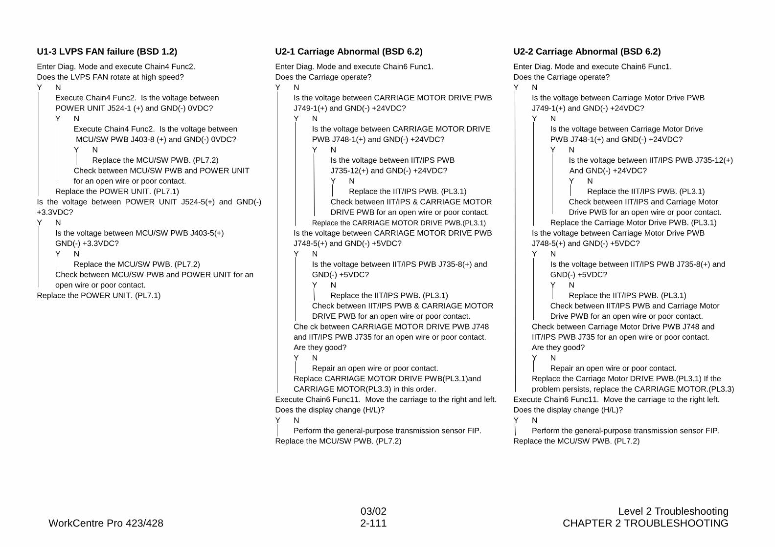
03/02 Level 2 TroubleshootingWorkCentre Pro 423/428 2-111 CHAPTER 2 TROUBLESHOOTING
U1-3 LVPS FAN failure (BSD 1.2)
Enter Diag. Mode and execute Chain4 Func2.Does the LVPS FAN rotate at high speed?Y N
Execute Chain4 Func2. Is the voltage betweenPOWER UNIT J524-1 (+) and GND(-) 0VDC?Y N
Execute Chain4 Func2. Is the voltage between MCU/SW PWB J403-8 (+) and GND(-) 0VDC?Y N
Replace the MCU/SW PWB. (PL7.2)Check between MCU/SW PWB and POWER UNITfor an open wire or poor contact.
Replace the POWER UNIT. (PL7.1)Is the voltage between POWER UNIT J524-5(+) and GND(-)+3.3VDC?Y N
Is the voltage between MCU/SW PWB J403-5(+)GND(-) +3.3VDC?Y N
Replace the MCU/SW PWB. (PL7.2)Check between MCU/SW PWB and POWER UNIT for anopen wire or poor contact.
Replace the POWER UNIT. (PL7.1)
U2-1 Carriage Abnormal (BSD 6.2)
Enter Diag. Mode and execute Chain6 Func1.Does the Carriage operate?Y N
Is the voltage between CARRIAGE MOTOR DRIVE PWBJ749-1(+) and GND(-) +24VDC?Y N
Is the voltage between CARRIAGE MOTOR DRIVEPWB J748-1(+) and GND(-) +24VDC?Y N
Is the voltage between IIT/IPS PWBJ735-12(+) and GND(-) +24VDC?Y N
Replace the IIT/IPS PWB. (PL3.1)Check between IIT/IPS & CARRIAGE MOTORDRIVE PWB for an open wire or poor contact.
Replace the CARRIAGE MOTOR DRIVE PWB.(PL3.1)Is the voltage between CARRIAGE MOTOR DRIVE PWBJ748-5(+) and GND(-) +5VDC?Y N
Is the voltage between IIT/IPS PWB J735-8(+) andGND(-) +5VDC?Y N
Replace the IIT/IPS PWB. (PL3.1)Check between IIT/IPS PWB & CARRIAGE MOTORDRIVE PWB for an open wire or poor contact.
Che ck between CARRIAGE MOTOR DRIVE PWB J748and IIT/IPS PWB J735 for an open wire or poor contact.Are they good?Y N
Repair an open wire or poor contact.Replace CARRIAGE MOTOR DRIVE PWB(PL3.1)andCARRIAGE MOTOR(PL3.3) in this order.
Execute Chain6 Func11. Move the carriage to the right and left.Does the display change (H/L)?Y N
Perform the general-purpose transmission sensor FIP.Replace the MCU/SW PWB. (PL7.2)
U2-2 Carriage Abnormal (BSD 6.2)
Enter Diag. Mode and execute Chain6 Func1.Does the Carriage operate?Y N
Is the voltage between Carriage Motor Drive PWBJ749-1(+) and GND(-) +24VDC?Y N
Is the voltage between Carriage Motor DrivePWB J748-1(+) and GND(-) +24VDC?Y N
Is the voltage between IIT/IPS PWB J735-12(+)And GND(-) +24VDC?Y N
Replace the IIT/IPS PWB. (PL3.1)Check between IIT/IPS and Carriage MotorDrive PWB for an open wire or poor contact.
Replace the Carriage Motor Drive PWB. (PL3.1)Is the voltage between Carriage Motor Drive PWBJ748-5(+) and GND(-) +5VDC?Y N
Is the voltage between IIT/IPS PWB J735-8(+) andGND(-) +5VDC?Y N
Replace the IIT/IPS PWB. (PL3.1)Check between IIT/IPS PWB and Carriage MotorDrive PWB for an open wire or poor contact.
Check between Carriage Motor Drive PWB J748 andIIT/IPS PWB J735 for an open wire or poor contact.Are they good?Y N
Repair an open wire or poor contact.Replace the Carriage Motor DRIVE PWB.(PL3.1) If theproblem persists, replace the CARRIAGE MOTOR.(PL3.3)
Execute Chain6 Func11. Move the carriage to the right left.Does the display change (H/L)?Y N
Perform the general-purpose transmission sensor FIP.Replace the MCU/SW PWB. (PL7.2)
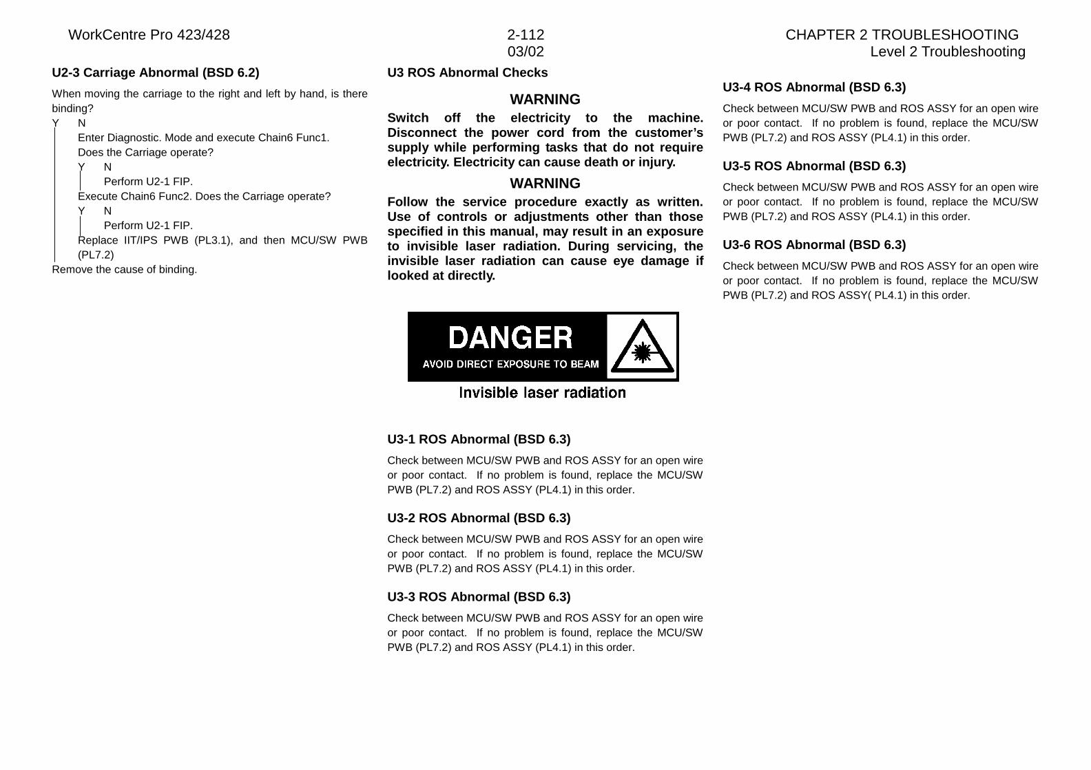
WorkCentre Pro 423/428 2-112 CHAPTER 2 TROUBLESHOOTING03/02 Level 2 Troubleshooting
U2-3 Carriage Abnormal (BSD 6.2)
When moving the carriage to the right and left by hand, is therebinding?Y N
Enter Diagnostic. Mode and execute Chain6 Func1.Does the Carriage operate?Y N
Perform U2-1 FIP.Execute Chain6 Func2. Does the Carriage operate?Y N
Perform U2-1 FIP.Replace IIT/IPS PWB (PL3.1), and then MCU/SW PWB(PL7.2)
Remove the cause of binding.
U3 ROS Abnormal Checks
WARNINGSwitch off the electricity to the machine.Disconnect the power cord from the customer’ssupply while performing tasks that do not requireelectricity. Electricity can cause death or injury.
WARNINGFollow the service procedure exactly as written.Use of controls or adjustments other than thosespecified in this manual, may result in an exposureto invisible laser radiation. During servicing, theinvisible laser radiation can cause eye damage iflooked at directly.
U3-1 ROS Abnormal (BSD 6.3)
Check between MCU/SW PWB and ROS ASSY for an open wireor poor contact. If no problem is found, replace the MCU/SWPWB (PL7.2) and ROS ASSY (PL4.1) in this order.
U3-2 ROS Abnormal (BSD 6.3)
Check between MCU/SW PWB and ROS ASSY for an open wireor poor contact. If no problem is found, replace the MCU/SWPWB (PL7.2) and ROS ASSY (PL4.1) in this order.
U3-3 ROS Abnormal (BSD 6.3)
Check between MCU/SW PWB and ROS ASSY for an open wireor poor contact. If no problem is found, replace the MCU/SWPWB (PL7.2) and ROS ASSY (PL4.1) in this order.
U3-4 ROS Abnormal (BSD 6.3)
Check between MCU/SW PWB and ROS ASSY for an open wireor poor contact. If no problem is found, replace the MCU/SWPWB (PL7.2) and ROS ASSY (PL4.1) in this order.
U3-5 ROS Abnormal (BSD 6.3)
Check between MCU/SW PWB and ROS ASSY for an open wireor poor contact. If no problem is found, replace the MCU/SWPWB (PL7.2) and ROS ASSY (PL4.1) in this order.
U3-6 ROS Abnormal (BSD 6.3)
Check between MCU/SW PWB and ROS ASSY for an open wireor poor contact. If no problem is found, replace the MCU/SWPWB (PL7.2) and ROS ASSY( PL4.1) in this order.
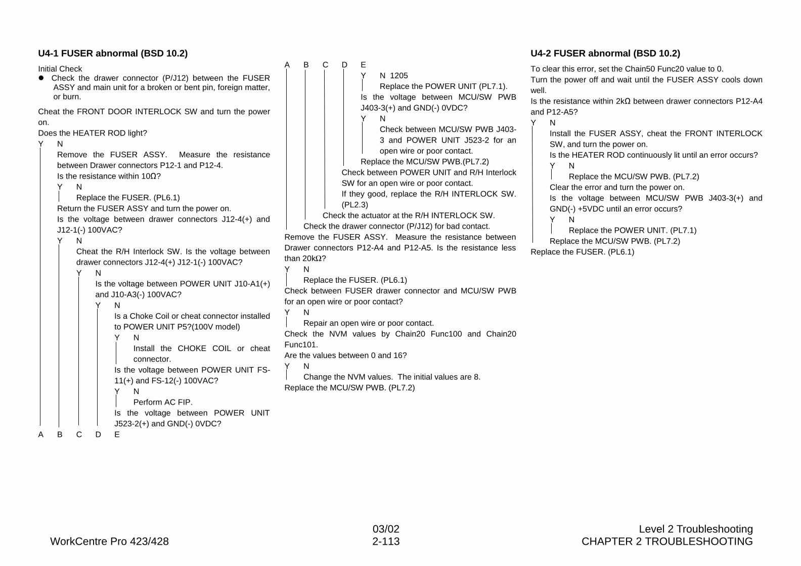
03/02 Level 2 TroubleshootingWorkCentre Pro 423/428 2-113 CHAPTER 2 TROUBLESHOOTING
U4-1 FUSER abnormal (BSD 10.2)
Initial Checkl Check the drawer connector (P/J12) between the FUSER
ASSY and main unit for a broken or bent pin, foreign matter,or burn.
Cheat the FRONT DOOR INTERLOCK SW and turn the poweron.Does the HEATER ROD light?Y N
Remove the FUSER ASSY. Measure the resistancebetween Drawer connectors P12-1 and P12-4.Is the resistance within 10�?Y N
Replace the FUSER. (PL6.1)Return the FUSER ASSY and turn the power on.Is the voltage between drawer connectors J12-4(+) andJ12-1(-) 100VAC?Y N
Cheat the R/H Interlock SW. Is the voltage betweendrawer connectors J12-4(+) J12-1(-) 100VAC?Y N
Is the voltage between POWER UNIT J10-A1(+)and J10-A3(-) 100VAC?Y N
Is a Choke Coil or cheat connector installedto POWER UNIT P5?(100V model)Y N
Install the CHOKE COIL or cheatconnector.
Is the voltage between POWER UNIT FS-11(+) and FS-12(-) 100VAC?Y N
Perform AC FIP.Is the voltage between POWER UNITJ523-2(+) and GND(-) 0VDC?
A B C D E
A B C D EY N 1205
Replace the POWER UNIT (PL7.1).Is the voltage between MCU/SW PWBJ403-3(+) and GND(-) 0VDC?Y N
Check between MCU/SW PWB J403-3 and POWER UNIT J523-2 for anopen wire or poor contact.
Replace the MCU/SW PWB.(PL7.2)Check between POWER UNIT and R/H InterlockSW for an open wire or poor contact.If they good, replace the R/H INTERLOCK SW.(PL2.3)
Check the actuator at the R/H INTERLOCK SW.Check the drawer connector (P/J12) for bad contact.
Remove the FUSER ASSY. Measure the resistance betweenDrawer connectors P12-A4 and P12-A5. Is the resistance lessthan 20k�?Y N
Replace the FUSER. (PL6.1)Check between FUSER drawer connector and MCU/SW PWBfor an open wire or poor contact?Y N
Repair an open wire or poor contact.Check the NVM values by Chain20 Func100 and Chain20Func101.Are the values between 0 and 16?Y N
Change the NVM values. The initial values are 8.Replace the MCU/SW PWB. (PL7.2)
U4-2 FUSER abnormal (BSD 10.2)
To clear this error, set the Chain50 Func20 value to 0.Turn the power off and wait until the FUSER ASSY cools downwell.Is the resistance within 2k� between drawer connectors P12-A4and P12-A5?Y N
Install the FUSER ASSY, cheat the FRONT INTERLOCKSW, and turn the power on.Is the HEATER ROD continuously lit until an error occurs?Y N
Replace the MCU/SW PWB. (PL7.2)Clear the error and turn the power on.Is the voltage between MCU/SW PWB J403-3(+) andGND(-) +5VDC until an error occurs?Y N
Replace the POWER UNIT. (PL7.1)Replace the MCU/SW PWB. (PL7.2)
Replace the FUSER. (PL6.1)
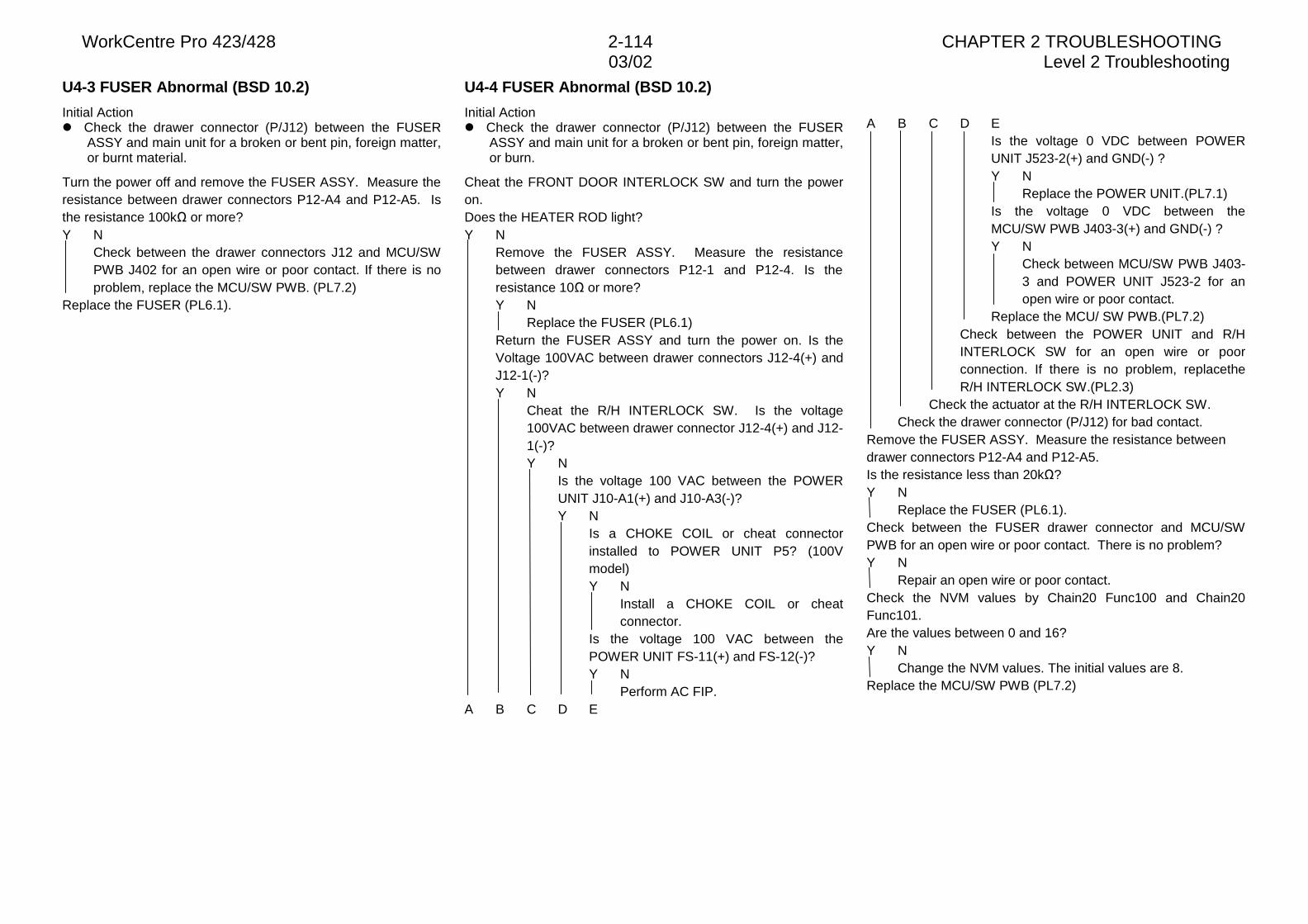
WorkCentre Pro 423/428 2-114 CHAPTER 2 TROUBLESHOOTING03/02 Level 2 Troubleshooting
U4-3 FUSER Abnormal (BSD 10.2)
Initial Actionl Check the drawer connector (P/J12) between the FUSER
ASSY and main unit for a broken or bent pin, foreign matter,or burnt material.
Turn the power off and remove the FUSER ASSY. Measure theresistance between drawer connectors P12-A4 and P12-A5. Isthe resistance 100k� or more?Y N
Check between the drawer connectors J12 and MCU/SWPWB J402 for an open wire or poor contact. If there is noproblem, replace the MCU/SW PWB. (PL7.2)
Replace the FUSER (PL6.1).
U4-4 FUSER Abnormal (BSD 10.2)
Initial Actionl Check the drawer connector (P/J12) between the FUSER
ASSY and main unit for a broken or bent pin, foreign matter,or burn.
Cheat the FRONT DOOR INTERLOCK SW and turn the poweron.Does the HEATER ROD light?Y N
Remove the FUSER ASSY. Measure the resistancebetween drawer connectors P12-1 and P12-4. Is theresistance 10� or more?Y N
Replace the FUSER (PL6.1)Return the FUSER ASSY and turn the power on. Is theVoltage 100VAC between drawer connectors J12-4(+) andJ12-1(-)?Y N
Cheat the R/H INTERLOCK SW. Is the voltage100VAC between drawer connector J12-4(+) and J12-1(-)?Y N
Is the voltage 100 VAC between the POWERUNIT J10-A1(+) and J10-A3(-)?Y N
Is a CHOKE COIL or cheat connectorinstalled to POWER UNIT P5? (100Vmodel)Y N
Install a CHOKE COIL or cheatconnector.
Is the voltage 100 VAC between thePOWER UNIT FS-11(+) and FS-12(-)?Y N
Perform AC FIP.A B C D E
A B C D EIs the voltage 0 VDC between POWERUNIT J523-2(+) and GND(-) ?Y N
Replace the POWER UNIT.(PL7.1)Is the voltage 0 VDC between theMCU/SW PWB J403-3(+) and GND(-) ?Y N
Check between MCU/SW PWB J403-3 and POWER UNIT J523-2 for anopen wire or poor contact.
Replace the MCU/ SW PWB.(PL7.2)Check between the POWER UNIT and R/HINTERLOCK SW for an open wire or poorconnection. If there is no problem, replacetheR/H INTERLOCK SW.(PL2.3)
Check the actuator at the R/H INTERLOCK SW.Check the drawer connector (P/J12) for bad contact.
Remove the FUSER ASSY. Measure the resistance betweendrawer connectors P12-A4 and P12-A5.Is the resistance less than 20k�?Y N
Replace the FUSER (PL6.1).Check between the FUSER drawer connector and MCU/SWPWB for an open wire or poor contact. There is no problem?Y N
Repair an open wire or poor contact.Check the NVM values by Chain20 Func100 and Chain20Func101.Are the values between 0 and 16?Y N
Change the NVM values. The initial values are 8.Replace the MCU/SW PWB (PL7.2)
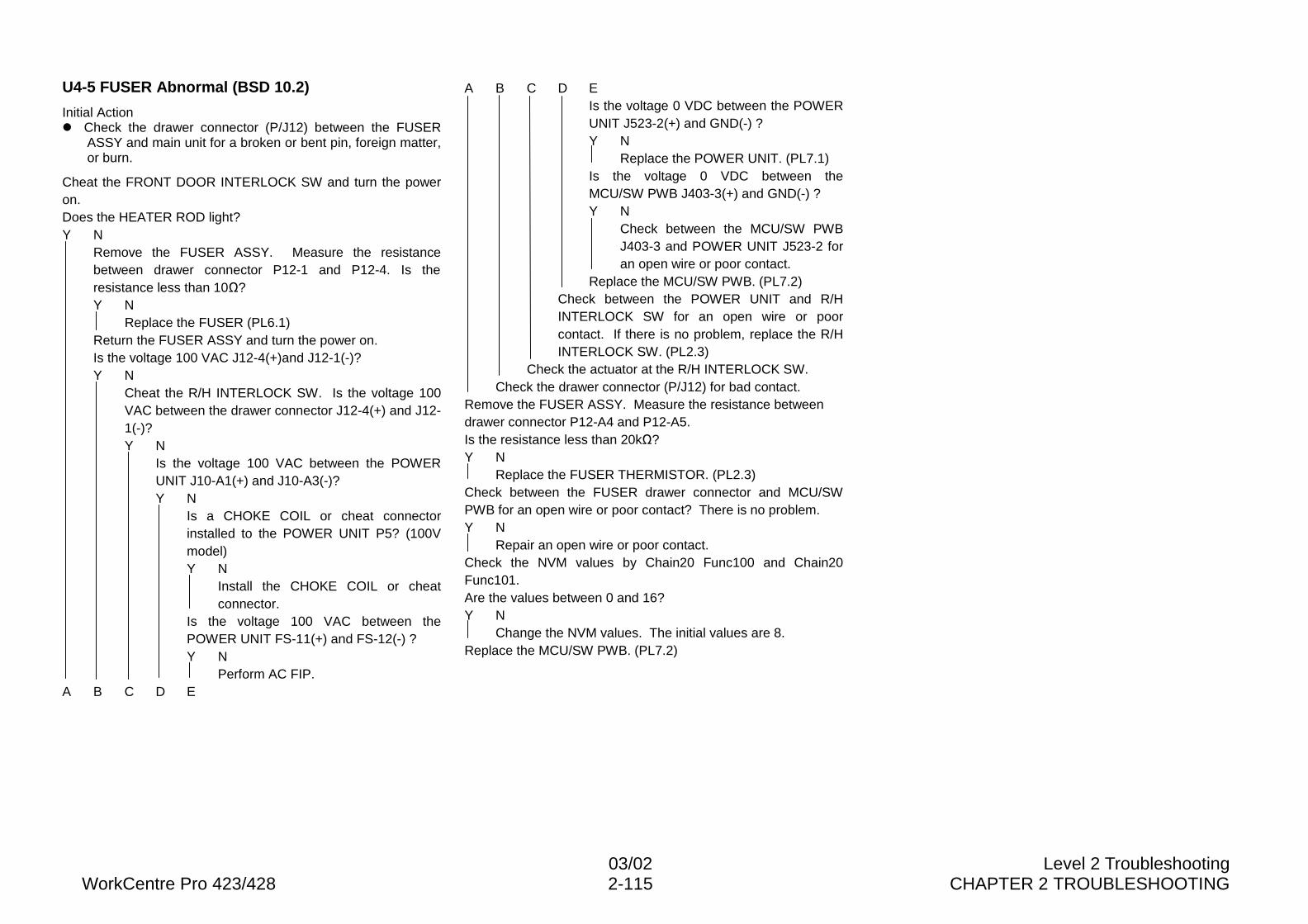
03/02 Level 2 TroubleshootingWorkCentre Pro 423/428 2-115 CHAPTER 2 TROUBLESHOOTING
U4-5 FUSER Abnormal (BSD 10.2)
Initial Actionl Check the drawer connector (P/J12) between the FUSER
ASSY and main unit for a broken or bent pin, foreign matter,or burn.
Cheat the FRONT DOOR INTERLOCK SW and turn the poweron.Does the HEATER ROD light?Y N
Remove the FUSER ASSY. Measure the resistancebetween drawer connector P12-1 and P12-4. Is theresistance less than 10�?Y N
Replace the FUSER (PL6.1)Return the FUSER ASSY and turn the power on.Is the voltage 100 VAC J12-4(+)and J12-1(-)?Y N
Cheat the R/H INTERLOCK SW. Is the voltage 100VAC between the drawer connector J12-4(+) and J12-1(-)?Y N
Is the voltage 100 VAC between the POWERUNIT J10-A1(+) and J10-A3(-)?Y N
Is a CHOKE COIL or cheat connectorinstalled to the POWER UNIT P5? (100Vmodel)Y N
Install the CHOKE COIL or cheatconnector.
Is the voltage 100 VAC between thePOWER UNIT FS-11(+) and FS-12(-) ?Y N
Perform AC FIP.A B C D E
A B C D EIs the voltage 0 VDC between the POWERUNIT J523-2(+) and GND(-) ?Y N
Replace the POWER UNIT. (PL7.1)Is the voltage 0 VDC between theMCU/SW PWB J403-3(+) and GND(-) ?Y N
Check between the MCU/SW PWBJ403-3 and POWER UNIT J523-2 foran open wire or poor contact.
Replace the MCU/SW PWB. (PL7.2)Check between the POWER UNIT and R/HINTERLOCK SW for an open wire or poorcontact. If there is no problem, replace the R/HINTERLOCK SW. (PL2.3)
Check the actuator at the R/H INTERLOCK SW.Check the drawer connector (P/J12) for bad contact.
Remove the FUSER ASSY. Measure the resistance betweendrawer connector P12-A4 and P12-A5.Is the resistance less than 20k�?Y N
Replace the FUSER THERMISTOR. (PL2.3)Check between the FUSER drawer connector and MCU/SWPWB for an open wire or poor contact? There is no problem.Y N
Repair an open wire or poor contact.Check the NVM values by Chain20 Func100 and Chain20Func101.Are the values between 0 and 16?Y N
Change the NVM values. The initial values are 8.Replace the MCU/SW PWB. (PL7.2)
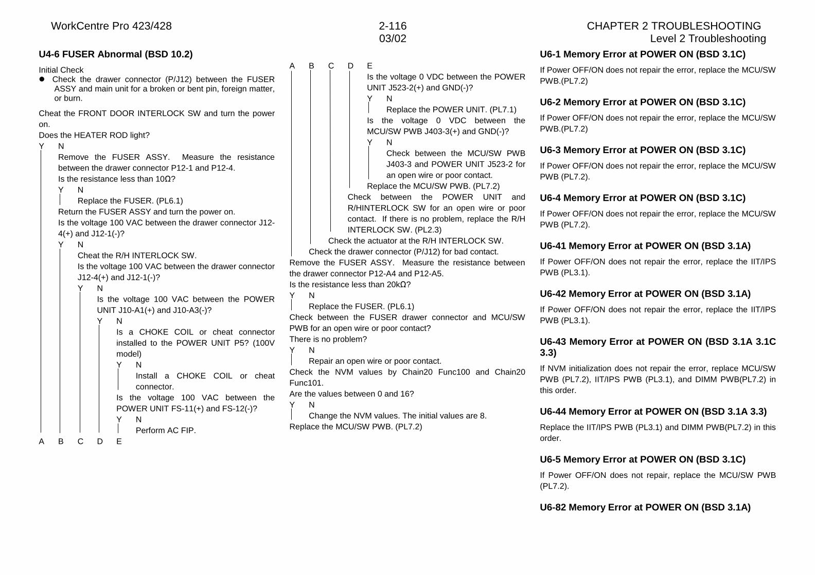
WorkCentre Pro 423/428 2-116 CHAPTER 2 TROUBLESHOOTING03/02 Level 2 Troubleshooting
U4-6 FUSER Abnormal (BSD 10.2)
Initial Checkl Check the drawer connector (P/J12) between the FUSER
ASSY and main unit for a broken or bent pin, foreign matter,or burn.
Cheat the FRONT DOOR INTERLOCK SW and turn the poweron.Does the HEATER ROD light?Y N
Remove the FUSER ASSY. Measure the resistancebetween the drawer connector P12-1 and P12-4.Is the resistance less than 10�?Y N
Replace the FUSER. (PL6.1)Return the FUSER ASSY and turn the power on.Is the voltage 100 VAC between the drawer connector J12-4(+) and J12-1(-)?Y N
Cheat the R/H INTERLOCK SW.Is the voltage 100 VAC between the drawer connectorJ12-4(+) and J12-1(-)?Y N
Is the voltage 100 VAC between the POWERUNIT J10-A1(+) and J10-A3(-)?Y N
Is a CHOKE COIL or cheat connectorinstalled to the POWER UNIT P5? (100Vmodel)Y N
Install a CHOKE COIL or cheatconnector.
Is the voltage 100 VAC between thePOWER UNIT FS-11(+) and FS-12(-)?Y N
Perform AC FIP.A B C D E
A B C D EIs the voltage 0 VDC between the POWERUNIT J523-2(+) and GND(-)?Y N
Replace the POWER UNIT. (PL7.1)Is the voltage 0 VDC between theMCU/SW PWB J403-3(+) and GND(-)?Y N
Check between the MCU/SW PWBJ403-3 and POWER UNIT J523-2 foran open wire or poor contact.
Replace the MCU/SW PWB. (PL7.2)Check between the POWER UNIT andR/HINTERLOCK SW for an open wire or poorcontact. If there is no problem, replace the R/HINTERLOCK SW. (PL2.3)
Check the actuator at the R/H INTERLOCK SW.Check the drawer connector (P/J12) for bad contact.
Remove the FUSER ASSY. Measure the resistance betweenthe drawer connector P12-A4 and P12-A5.Is the resistance less than 20k�?Y N
Replace the FUSER. (PL6.1)Check between the FUSER drawer connector and MCU/SWPWB for an open wire or poor contact?There is no problem?Y N
Repair an open wire or poor contact.Check the NVM values by Chain20 Func100 and Chain20Func101.Are the values between 0 and 16?Y N
Change the NVM values. The initial values are 8.Replace the MCU/SW PWB. (PL7.2)
U6-1 Memory Error at POWER ON (BSD 3.1C)
If Power OFF/ON does not repair the error, replace the MCU/SWPWB.(PL7.2)
U6-2 Memory Error at POWER ON (BSD 3.1C)
If Power OFF/ON does not repair the error, replace the MCU/SWPWB.(PL7.2)
U6-3 Memory Error at POWER ON (BSD 3.1C)
If Power OFF/ON does not repair the error, replace the MCU/SWPWB (PL7.2).
U6-4 Memory Error at POWER ON (BSD 3.1C)
If Power OFF/ON does not repair the error, replace the MCU/SWPWB (PL7.2).
U6-41 Memory Error at POWER ON (BSD 3.1A)
If Power OFF/ON does not repair the error, replace the IIT/IPSPWB (PL3.1).
U6-42 Memory Error at POWER ON (BSD 3.1A)
If Power OFF/ON does not repair the error, replace the IIT/IPSPWB (PL3.1).
U6-43 Memory Error at POWER ON (BSD 3.1A 3.1C3.3)
If NVM initialization does not repair the error, replace MCU/SWPWB (PL7.2), IIT/IPS PWB (PL3.1), and DIMM PWB(PL7.2) inthis order.
U6-44 Memory Error at POWER ON (BSD 3.1A 3.3)
Replace the IIT/IPS PWB (PL3.1) and DIMM PWB(PL7.2) in thisorder.
U6-5 Memory Error at POWER ON (BSD 3.1C)
If Power OFF/ON does not repair, replace the MCU/SW PWB(PL7.2).
U6-82 Memory Error at POWER ON (BSD 3.1A)
03/02 Level 2 TroubleshootingWorkCentre Pro 423/428 2-117 CHAPTER 2 TROUBLESHOOTING
If Power OFF/ON does not repair, replace the IIT/IPSPWB.(PL3.1)U6-95 Memory Error at POWER ON (BSD 3.1A 3.1C3.3)
If NVM initialization does not repair the error, replace theMCU/SW PWB(PL7.2), IIT/IPS PWB(PL3.1), and DIMMPWB(PL7.2) in this order.
U7-31 Inter-system Communication FAIL (BSD3.1B)
Check between the MCU/SW PWB and IIT/IPS PWB andbetween the IIT/IPS PWB and UI PWB for an open wire or poorcontact.If no problem is found, replace the MCU/SW PWB(PL7.2), UIPWB(PLXX.X), and IIT/IPS PWB(PL3.1) in this order.
U7-32 Inter-system Communication FAIL (BSD3.1B)
Check between the MCU/SW PWB and IIT/IPS PWB andbetween the IIT/IPS PWB and UI PWB for an open wire or poorcontact.If no problem is found, replace the MCU/SW PWB(PL7.2), UIPWB(PLXX.X), and IIT/IPS PWB(PL3.1) in this order.
U7-33 Inter-system Communication FAIL (BSD3.1B)
Check between the MCU/SW PWB and IIT/IPS PWB andbetween the IIT/IPS PWB and UI PWB for an open wire or poorcontact.If no problem is found, replace the MCU/SW PWB(PL7.2), UIPWB(PLXX.X), and IIT/IPS PWB(PL3.1) in this order.
U7-34 Inter-system Communication FAIL (BSD3.1B)
Check between the MCU/SW PWB and IIT/IPS PWB andbetween the IIT/IPS PWB and UI PWB for an open wire or poorcontact.If no problem is found, replace the MCU/SW PWB(PL7.2), UIPWB(PLXX.X), and IIT/IPS PWB(PL3.1) in this order.
U7-35 Inter-system Communication FAIL (BSD
3.1B)
Check between the MCU/SW PWB and IIT/IPS PWB andbetween the IIT/IPS PWB and UI PWB for an open wire or poorcontact.If no problem is found, replace the MCU/SW PWB(PL7.2), UIPWB(PLXX.X), and IIT/IPS PWB(PL3.1) in this order.
U7-41 Inter-system Communication FAIL (BSD3.1A)
Check between the MCU/SW PWB and IIT/IPS PWB for an openwire or poor contact. If no problem is found, replace theMCU/SW PWB(PL7.2)and IIT/IPS PWB(PL3.1) in this order.
U7-42 Inter-system Communication FAIL (BSD3.1A)
Check between the MCU/SW PWB and IIT/IPS PWB for an openwire or poor contact. If no problem is found, replace theMCU/SW PWB(PL7.2)and IIT/IPS PWB(PL3.1) in this order.
U7-42 Inter-system Communication FAIL (BSD3.1A)
Check between the MCU/SW PWB and IIT/IPS PWB for an openwire or poor contact. If no problem is found, replace theMCU/SW PWB(PL7.2) and IIT/IPS PWB(PL3.1) in this order.
U7-43 Inter-system Communication FAIL (BSD3.1A)
Check between the MCU/SW PWB and IIT/IPS PWB for an openwire or poor contact. If no problem is found, replace theMCU/SW PWB(PL7.2)and IIT/IPS PWB(PL3.1) in this order.
U7-44 Inter-system Communication FAIL (BSD3.1A)
Check between the MCU/SW PWB and IIT/IPS PWB for an openwire or poor contact. If no problem is found, replace theMCU/SW PWB(PL7.2)and IIT/IPS PWB(PL3.1) in this order.
U7-45 Inter-system Communication FAIL (BSD3.1A)
Check between the MCU/SW PWB and IIT/IPS PWB for an open
wire or poor contact. If no problem is found, replace theMCU/SW PWB(PL7.2)and IIT/IPS PWB(PL3.1) in this order.
U8-3 LAMP/CCD Sensor Abnormal (BSD 6.1B 6.2)
Problem factors:l CCD PWB defect
l IIT/IPS PWB defect
l MCU/SW PWB defect
l EXPOSURE LAMP quantity of light not appropriate
U8-4 LAMP/CCD Sensor Abnormal (BSD 6.1B 6.2)
Problem factors:l CCD PWB defect
l IIT/IPS PWB defect
l MCU/SW PWB defect
l EXPOSURE LAMP quantily of light not appropriate
U8-5 LAMP/CCD Sensor Abnormal (BSD 6.1B 6.2)
Problem factors:l CCD PWB defect
l IIT/IPS PWB defect
l MCU/SW PWB defect
l EXPOSURE LAMP quantily of light not appropriate
U8-6 LAMP/CCD Sensor Abnormal (BSD 6.1B 6.2)
Problem factors:l CCD PWB defect
l IIT/IPS PWB defect
l MCU/SW PWB defect
l EXPOSURE LAMP quantily of light not appropriate
l Reflector plate dirty or condensed
U9-1 MCU/SW PWB Failure (BSD 3.1C)
If Power OFF/ON does not rsolve the problem, replace theMCU/SW PWB (PL7.2).
WorkCentre Pro 423/428 2-118 CHAPTER 2 TROUBLESHOOTING03/02 Level 2 Troubleshooting
U9-31 MCU/SW PWB Failure (BSD 3.1C)
If Power OFF/ON does not solve the problem, replace theMCU/SW PWB (PL7.2).
U9-32 MCU/SW PWB Failure (BSD 3.1C)
If Power OFF/ON does not solve the problem, replace theMCU/SW PWB (PL7.2).
U9-33 MCU/SW PWB Failure (BSD 3.1C)
If Power OFF/ON does not solve the problem, replace theMCU/SW PWB (PL7.2).
U9-41 MCU/SW PWB Failure (BSD 3.1C)
If Power OFF/ON does not solve the problem, replace theMCU/SW PWB (PL7.2).
H5-61 FINISHER Interface Abnormal (BSD 3.1E)
Check between the MCU/SW PWB and FINISHER CONT PWBfor an open wire or poor contact. If no problem is found, replacethe MCU/SW PWB (PL7.2) and FINISHER CONT PWB(PL13.16) in this order.
H5-62 FINISHER Interface Abnormal (BSD 3.1E)
Check between the MCU/SW PWB and FINISHER CONT PWBfor an open wire or poor contact. If no problem is found, replacethe MCU/SW PWB (PL7.2) and FINISHER CONT PWB(PL13.16) in this order.
H5-63 FINISHER Interface Abnormal (BSD 3.1E)
Check between the MCU/SW PWB and FINISHER CONT PWBfor an open wire or poor contact. If no problem is found, replacethe MCU/SW PWB (PL7.2) and FINISHER CONT PWB(PL13.16) in this order.
H5-64 FINISHER Interface Abnormal (BSD 3.1E)
Check between the MCU/SW PWB and FINISHER CONT PWBfor an open wire or poor contact. If no problem is found, replacethe MCU/SW PWB (PL7.2) and FINISHER CONT PWB(PL13.16) in this order.
H5-81 FINISHER Failure (BSD 12.8)
Enter Diag. Mode and execute Chain12 Func22.Does the COMPILE MOTOR rotate?Y N
Execute Chain12 Func22. Is each voltage +12 VDCbetween FINISHER CONT PWB CN12-1/2/3/4(+) andGND(-) ?Y N
Is the voltage +24 VDC between the FINISHERCONT PWB CN1-1(+) and GND(-) ?Y N
Perform +24VDC FIP.Replace the FINISHER CONT PWB. (PL13.16)
Check between the FINISHER CONT PWB andCOMPILEMOTOR for an open wire or poor contact. If noproblem is found, replace the COMPILE MOTOR.(PL13.12)
Execute Chain12 Func5. Turn on and off the TAMPER HOMEPOSITION SENSOR with the tamper.Does the display change (H/L)?Y N
Perform the General-purpose transmission sensor FIP.Check the actuator at the TAMPER HOME POSITION SENSOR.If no problem is found, replace the FINISHER CONT PWB(PL13.16).
H5-82 FINISHER Failure (BSD 12.10)
Are the TOP COVER and FRONT DOOR closed securely?Y N
Close the TOP COVER or FRONT DOOR.Enter Diag. Mode and execute Chain12 Func29.Does the STAPLE MOTOR rotate?Y N
Check between CN10 of the FINISHER CONT PWB andthe STAPLER UNIT for an open wire or poor contact.The connection is normal?Y N
Repair an open wire or poor contact.Replace the STAPLE HEAD. (PL13.3)
Turn the power off and remove the STAPLE HEAD. Turn thepower on with the connector connected and execute Chain12Func16. Turn the STAPLE MOTOR gear manually.Does the display change (H/L)?Y N
Check between CN10 of the FINISHER CONT PWB andSTAPLER UNIT for an open wire or poor contact.The connection is normal.Y N
Repair an open wire or poor contact.Replace the STAPLE HEAD. (PL13.3)
Replace the MCU/SW PWB. (PL7.2)
03/02 Level 2 TroubleshootingWorkCentre Pro 423/428 2-119 CHAPTER 2 TROUBLESHOOTING
H5-83 FINISHER Failure (BSD12.11)
Enter Diag. Mode and excute Chain12 Func27 or 28.Does the FINISHER TRAY ELEVATOR MOTOR rotate?Y N
Execute Chain12 Func27 or 28. Is each voltage +24 VDCbetween the FINISHER CONT PWB CN6-1/2(+) andGND(-) ?Y N
Is the voltage +24VDC between the FINISHER CONTPWB CN1-1(+) and GND(-) ?Y N
Perform +24VDC FIP.Replace the FINISHER CONT PWB. (PL13.16)
Check between the FINISHER CONT PWB CN6 and TRAYELEVATOR MOTOR for an open wire or poor contact.The connection is normal.Y N
Repair an open wire or poor contact.Replace the TRAY ELEVATOR MOTOR. (PL13.18)
Execute Chain12 Func12. Push the Paper press lever up anddown. Does the display change (H/L)?Y N
Perform the General-purpose transmittion sensor FIP.Remove the FINISHER RECIVING TRAY. Execute Chain12Func13.Turn the UPPER LIMIT SENSOR on and off with paper.Does the display change?Y N
Perform the General-purpose transmittion sensor FIP.Execute Chain12 Func14. Turn the NEAR FULL SENSOR onand off with paper. Does the display change (H/L)?Y N
Perform the General-purpose transmittion sensor FIP.Replace the MCU/SW PWB. (PL7.2)
H5-84 FINISHER Failure (BSD 12.10)
Check the removal of screw that secures (for delivery only)STAPLE UNIT.Check between the FINISHER CONT PWB CN10 and STAPLEUNIT for an open wire or poor contact. If no problem is found,replace the STAPLE HEAD (PL13.3), FINISHER CONT PWB(PL13.16), and MCU/SW PWB(PL7.2) in this order.H6-63 DADF Failure (BSD 3.1D)
If initialization does not clear the problem, replace the DADFCONT PWB. (PLXX.X)
H6-64 DADF Failure (BSD 3.1D)
If initialization does not clear the problem, replace the DADFCONT PWB. (PLXX.X)
H6-71 DADF Failure (BSD 3.1D)
Check between the IIT/IPS PWB and DADF CONT PWB for anopen wire or poor contact. If no problem is found, replace theDADF CONT PWB(PLXX.X), IIT/IPS PWB(PL3.1), and MCU/SWPWB(PL7.2) in this order.
H6-72 DADF Failure (BSD 3.1D)
Check between the IIT/IPS PWB and DADF CONT PWB for anopen wire or poor contact. If no problem is found, replace theDADF CONT PWB(PLXX.X), IIT/IPS PWB(PL3.1), and MCU/SWPWB(PL7.2) in this order.
H6-73 DADF Failure (BSD 3.1D)
Check between the IIT/IPS PWB and DADF CONT PWB for anopen wire or poor contact. If no problem is found, replace theDADF CONT PWB(PLXX.X), IIT/IPS PWB(PL3.1), and MCU/SWPWB(PL7.2) in this order.
H6-74 DADF Failure (BSD 3.1D)
Check between the IIT/IPS PWB and DADF CONT PWB for anopen wire or poor contact. If no problem is found, replace theDADF CONT PWB (PLXX.X), IIT/IPS PWB(PL3.1), andMCU/SW PWB(PL7.2) in this order.
H6-75 DADF Failure (BSD 3.1D)
Check between the IIT/IPS PWB and DADF CONT PWB for anopen wire or poor contact. If no problem is found, replace theDADF CONT PWB(PLXX.X), IIT/IPS PWB(PL3.1), and MCU/SWPWB(PL7.2) in this order.
H8-2 Page Memory Failure (BSD 3.1C)
Check the memory connector on the MCU/SW PWB. If noproblem is found, replace the MCU/SW PWB. (PL7.2)
H8-65 Page Memory Failure (BSD 3.1C)
Check the memory connector on the MCU/SW PWB. If noproblem is found, replace the MCU/SW PWB. (PL7.2)
H8-66 Page Memory Failure (BSD 3.1C)
Check the memory connector on the MCU/SW PWB. If noproblem is found, replace the optional memory.(PL7.2) If theproblem still does not recover, replace the MCU/SWPWB.(PL7.2)
H8-67 Page Memory Failure (BSD 3.1C)
Check the memory connector on the MCU/SW PWB. If noproblem is found, replace the MCU/SW PWB. (PL7.2)
H8-68 Page Memory Failure (BSD 3.1C)
Check the memory connector on the MCU/SW PWB. If noproblem is found, replace the MCU/SW PWB. (PL7.2)
HD-01 Hard Disk Failure (BSD 3.1C)
Check between the HDC PWB and HDD for an open wire orpoor contact. If no problem is found, replace the HDD. (PL7.2)
HD-02 Hard Disk Failure (BSD 3.1C)
Check between the HDC PWB and HDD for an open wire orpoor contact. If no problem is found, replace the HDD. (PL7.2)
WorkCentre Pro 423/428 2-120 CHAPTER 2 TROUBLESHOOTING03/02 Level 2 Troubleshooting
HD-03 Hard Disk Failure (BSD 3.1C)
Check between the HDC PWB and HDD for an open wire orpoor contact. If no problem is found, replace the HDD. (PL7.2)
HD-10 Hard Disk Failure (BSD 3.1C)
Check between the HDC PWB and HDD for an open wire orpoor contact. If no problem is found, replace the HDD. (PL7.2)
HD-71 Hard Disk Interface Abnormal (BSD 3.1C)
Check between the HDC PWB and HDD and between the HDCPWB and MCU/SW PWB for an open wire or poor contact. If noproblem is found, replace the HDD (PL7.2), HDC PWB(PL7.2),and MCU/SW PWB(PL7.2) in this order.
HD-72 Hard Disk Interface Abnormal (BSD 3.1C)
Check between the HDC PWB and HDD and between the HDCPWB and MCU/SW PWB for an open wire or poor contact. If noproblem is found, replace the HDD (PL7.2), HDC PWB (PL7.2),and MCU/SW PWB(PL7.2) in this order.
HD-73 Hard Disk Interface Abnormal (BSD 3.1C)
Check between the HDC PWB and HDD and between the HDCPWB and MCU/SW PWB for an open wire or poor contact. If noproblem is found, replace the HDD (PL7.2), HDC PWB (PL7.2),and MCU/SW PWB (PL7.2) in this order.
HD-74 Hard Disk Interface Abnormal (BSD 3.1C)
Check between the HDC PWB and HDD and between the HDCPWB and MCU/SW PWB for an open wire or poor contact. If noproblem is found, replace the HDD (PL7.2), HDC PWB (PL7.2),and MCU/SW PWB(PL7.2) in this order.
HD-75 Hard Disk Interface Abnormal (BSD 3.1C)
Check between the HDC PWB and HDD and between the HDCPWB and MCU/SW PWB for an open wire or poor contact. If noproblem is found, replace the HDD (PL7.2), HDC PWB(PL7.2),and MCU/SW PWB(PL7.2) in this order.
E1-1 REGI SENSOR Jam (BSD 8.5)
Chain Link Codes for Checkl [Chain 8 Func 5] REGI SENSOR
l [Chain 8 Func 10] REGI CLUTCH
Check Itemsl REGI SENSOR operation error
l REGI SENSOR actuator broken or missing
l REGI CLUTCH operation error
l REGI ROLL dirt, worn, or operation error
l Transport error due to foreign matter on paper path
l MAIN MOTOR rotation error
E1-2 REGI SENSOR Jam (BSD 8.5 10.3)
Chain Link Codes for Checkl [Chain4 Func1] MAIN MOTOR
l [Chain10 Func23] FUSER EXIT SENSOR
Check Itemsl FUSER EXIT SENSOR operation error
l FUSER EXIT SENSOR actuator broken or missing
l DRUM rotation error
l FUSER ROLL rotation error
l ROLL dirt, worn, or operation error
l Transport error due to foreign matter on paper path
l MAIN MOTOR rotation error
E1-6 REGI SENSOR Jam (BSD 8.5)
Chain Link Codes for Checkl [Chain 8 Func 5] REGI SENSOR
Check Itemsl Supply voltage drop at customer
l Check the circuit between the REGI SENSOR and MCU/SWPWB. If no problem is found, replace the REGISENSOR.(PLXX.X)
E3-1 FUSER Jam (BSD 10.3 10.5)
Chain Link Codes for Checkl [Chain 10 Func 23] FUSER EXIT SENSOR
l [Chain 10 Func 61] EXIT MOTOR
Check Itemsl FUSER EXIT SENSOR defect
l FUSER EXIT SENSOR actuator broken or missing
l DECURLER ROLL rotation error
l EXIT MOTOR defect
l Transport error due to foreign matter on paper path
E3-6 FUSER Jam (BSD 10.3)
Chain Link Codes for Checkl [Chain 10 Func 23] FUSER EXIT SENSOR
Check Itemsl Supply voltage drop at customer
l Check the circuit between the FUSER EXIT SENSOR andMCU/SW PWB. If no problem is found, replace the FUSEREXIT SENSOR. (PL6.1)
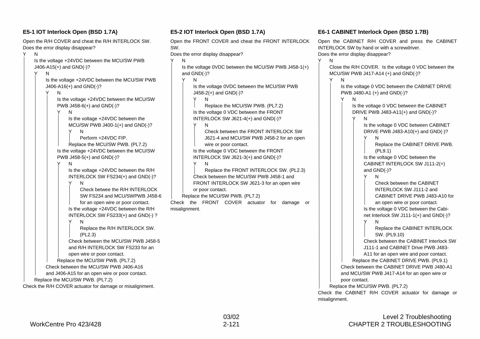
03/02 Level 2 TroubleshootingWorkCentre Pro 423/428 2-121 CHAPTER 2 TROUBLESHOOTING
E5-1 IOT Interlock Open (BSD 1.7A)
Open the R/H COVER and cheat the R/H INTERLOCK SW.Does the error display disappear?Y N
Is the voltage +24VDC between the MCU/SW PWBJ406-A15(+) and GND(-)?Y N
Is the voltage +24VDC between the MCU/SW PWBJ406-A16(+) and GND(-)?Y N
Is the voltage +24VDC between the MCU/SWPWB J458-6(+) and GND(-)?Y N
Is the voltage +24VDC between theMCU/SW PWB J400-1(+) and GND(-)?Y N
Perform +24VDC FIP.Replace the MCU/SW PWB. (PL7.2)
Is the voltage +24VDC between the MCU/SWPWB J458-5(+) and GND(-)?Y N
Is the voltage +24VDC between the R/HINTERLOCK SW FS234(+) and GND(-)?Y N
Check betwee the R/H INTERLOCKSW FS234 and MCU/SWPWB J458-6for an open wire or poor contact.
Is the voltage +24VDC between the R/HINTERLOCK SW FS233(+) and GND(-) ?Y N
Replace the R/H INTERLOCK SW.(PL2.3)
Check between the MCU/SW PWB J458-5and R/H INTERLOCK SW FS233 for anopen wire or poor contact.
Replace the MCU/SW PWB. (PL7.2)Check between the MCU/SW PWB J406-A16and J406-A15 for an open wire or poor contact.
Replace the MCU/SW PWB. (PL7.2)Check the R/H COVER actuator for damage or misalignment.
E5-2 IOT Interlock Open (BSD 1.7A)
Open the FRONT COVER and cheat the FRONT INTERLOCKSW.Does the error display disappear?Y N
Is the voltage 0VDC between the MCU/SW PWB J458-1(+)and GND(-)?Y N
Is the voltage 0VDC between the MCU/SW PWBJ458-2(+) and GND(-)?Y N
Replace the MCU/SW PWB. (PL7.2)Is the voltage 0 VDC between the FRONTINTERLOCK SW J621-4(+) and GND(-)?Y N
Check between the FRONT INTERLOCK SWJ621-4 and MCU/SW PWB J458-2 for an openwire or poor contact.
Is the voltage 0 VDC between the FRONTINTERLOCK SW J621-3(+) and GND(-)?Y N
Replace the FRONT INTERLOCK SW. (PL2.3)Check between the MCU/SW PWB J458-1 andFRONT INTERLOCK SW J621-3 for an open wireor poor contact.
Replace the MCU/SW PWB. (PL7.2)Check the FRONT COVER actuator for damage ormisalignment.
E6-1 CABINET Interlock Open (BSD 1.7B)
Open the CABINET R/H COVER and press the CABINETINTERLOCK SW by hand or with a screwdriver.Does the error display disappear?Y N
Close the R/H COVER. Is the voltage 0 VDC between theMCU/SW PWB J417-A14 (+) and GND(-)?Y N
Is the voltage 0 VDC between the CABINET DRIVEPWB J480-A1 (+) and GND(-)?Y N
Is the voltage 0 VDC between the CABINETDRIVE PWB J483-A11(+) and GND(-)?Y N
Is the voltage 0 VDC between CABINETDRIVE PWB J483-A10(+) and GND(-)?Y N
Replace the CABINET DRIVE PWB.(PL9.1)
Is the voltage 0 VDC between theCABINET INTERLOCK SW J111-2(+)and GND(-)?Y N
Check between the CABINETINTERLOCK SW J111-2 andCABINET DRIVE PWB J483-A10 foran open wire or poor contact.
Is the voltage 0 VDC between the Cabi-net Interlock SW J111-1(+) and GND(-)?Y N
Replace the CABINET INTERLOCKSW. (PL9.10)
Check between the CABINET Interlock SWJ111-1 and CABINET Drive PWB J483-A11 for an open wire and poor contact.
Replace the CABINET DRIVE PWB. (PL9.1)Check between the CABINET DRIVE PWB J480-A1and MCU/SW PWB J417-A14 for an open wire orpoor contact.
Replace the MCU/SW PWB. (PL7.2)Check the CABINET R/H COVER actuator for damage ormisalignment.
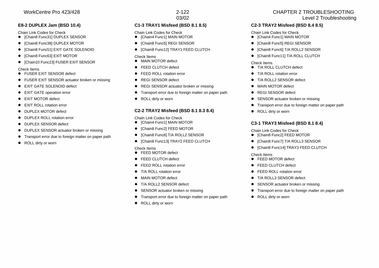
WorkCentre Pro 423/428 2-122 CHAPTER 2 TROUBLESHOOTING03/02 Level 2 Troubleshooting
E8-2 DUPLEX Jam (BSD 10.4)
Chain Link Codes for Checkl [Chain8 Func31] DUPLEX SENSOR
l [Chain8 Func38] DUPLEX MOTOR
l [Chain8 Func51] EXIT GATE SOLENOID
l [Chain8 Func63] EXIT MOTOR
l [Chain10 Func23] FUSER EXIT SENSOR
Check Itemsl FUSER EXIT SENSOR defect
l FUSER EXIT SENSOR actuator broken or missing
l EXIT GATE SOLENOID defect
l EXIT GATE operation error
l EXIT MOTOR defect
l EXIT ROLL rotation error
l DUPLEX MOTOR defect
l DUPLEX ROLL rotation error
l DUPLEX SENSOR defect
l DUPLEX SENSOR actuator broken or missing
l Transport error due to foreign matter on paper path
l ROLL dirty or worn
C1-3 TRAY1 Misfeed (BSD 8.1 8.5)
Chain Link Codes for Checkl [Chain4 Func1] MAIN MOTOR
l [Chain8 Func5] REGI SENSOR
l [Chain8 Func12] TRAY1 FEED CLUTCH
Check Itemsl MAIN MOTOR defect
l FEED CLUTCH defect
l FEED ROLL rotation error
l REGI SENSOR defect
l REGI SENSOR actuator broken or missing
l Transport error due to foreign matter on paper path
l ROLL dirty or worn
C2-2 TRAY2 Misfeed (BSD 8.1 8.3 8.4)
Chain Link Codes for Checkl [Chain4 Func1] MAIN MOTOR
l [Chain8 Func2] FEED MOTOR
l [Chain8 Func6] T/A ROLL2 SENSOR
l [Chain8 Func13] TRAY2 FEED CLUTCH
Check Itemsl FEED MOTOR defect
l FEED CLUTCH defect
l FEED ROLL rotation error
l T/A ROLL rotation error
l MAIN MOTOR defect
l T/A ROLL2 SENSOR defect
l SENSOR actuator broken or missing
l Transport error due to foreign matter on paper path
l ROLL dirty or worn
C2-3 TRAY2 Misfeed (BSD 8.4 8.5)
Chain Link Codes for Checkl [Chain4 Func1] MAIN MOTOR
l [Chain8 Func5] REGI SENSOR
l [Chain8 Func6] T/A ROLL2 SENSOR
l [Chain8 Func11] T/A ROLL CLUTCH
Check Itemsl T/A ROLL CLUTCH defect
l T/A ROLL rotation error
l T/A ROLL2 SENSOR defect
l MAIN MOTOR defect
l REGI SENSOR defect
l SENSOR actuator broken or missing
l Transport error due to foreign matter on paper path
l ROLL dirty or worn
C3-1 TRAY3 Misfeed (BSD 8.1 8.4)
Chain Link Codes for Checkl [Chain8 Func2] FEED MOTOR
l [Chain8 Func7] T/A ROLL3 SENSOR
l [Chain8 Func14] TRAY3 FEED CLUTCH
Check Itemsl FEED MOTOR defect
l FEED CLUTCH defect
l FEED ROLL rotation error
l T/A ROLL3 SENSOR defect
l SENSOR actuator broken or missing
l Transport error due to foreign matter on paper path
l ROLL dirty or worn
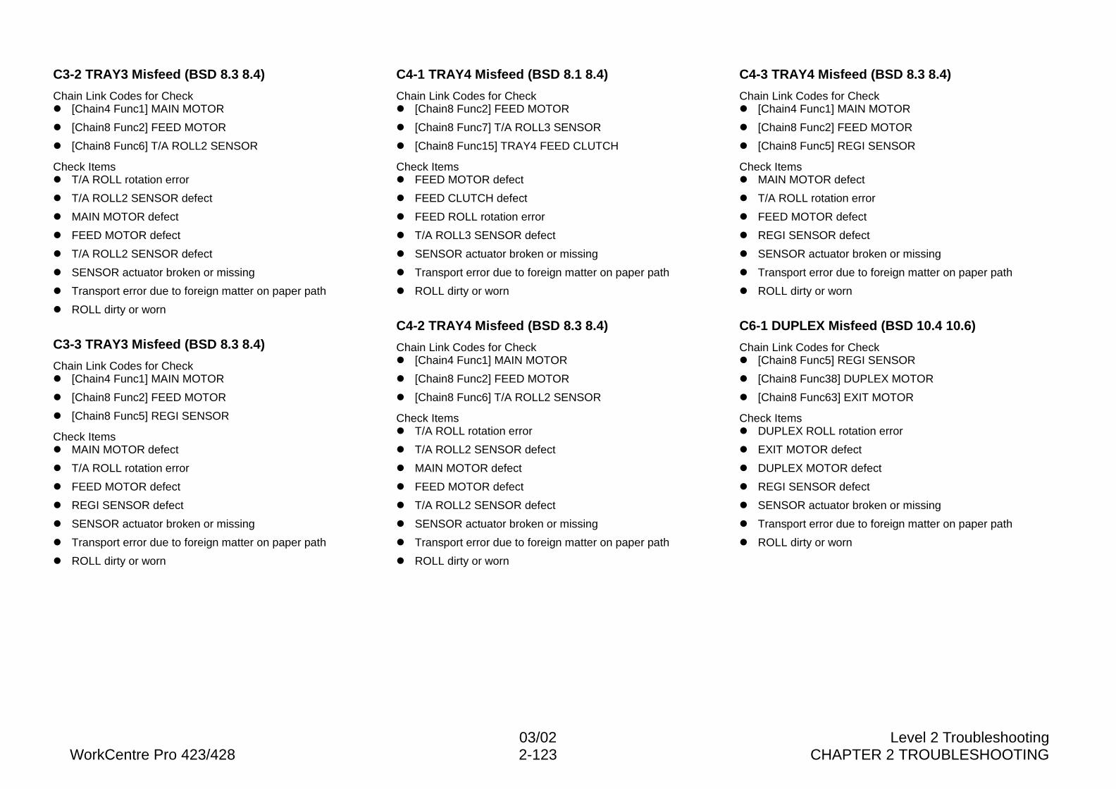
03/02 Level 2 TroubleshootingWorkCentre Pro 423/428 2-123 CHAPTER 2 TROUBLESHOOTING
C3-2 TRAY3 Misfeed (BSD 8.3 8.4)
Chain Link Codes for Checkl [Chain4 Func1] MAIN MOTOR
l [Chain8 Func2] FEED MOTOR
l [Chain8 Func6] T/A ROLL2 SENSOR
Check Itemsl T/A ROLL rotation error
l T/A ROLL2 SENSOR defect
l MAIN MOTOR defect
l FEED MOTOR defect
l T/A ROLL2 SENSOR defect
l SENSOR actuator broken or missing
l Transport error due to foreign matter on paper path
l ROLL dirty or worn
C3-3 TRAY3 Misfeed (BSD 8.3 8.4)
Chain Link Codes for Checkl [Chain4 Func1] MAIN MOTOR
l [Chain8 Func2] FEED MOTOR
l [Chain8 Func5] REGI SENSOR
Check Itemsl MAIN MOTOR defect
l T/A ROLL rotation error
l FEED MOTOR defect
l REGI SENSOR defect
l SENSOR actuator broken or missing
l Transport error due to foreign matter on paper path
l ROLL dirty or worn
C4-1 TRAY4 Misfeed (BSD 8.1 8.4)
Chain Link Codes for Checkl [Chain8 Func2] FEED MOTOR
l [Chain8 Func7] T/A ROLL3 SENSOR
l [Chain8 Func15] TRAY4 FEED CLUTCH
Check Itemsl FEED MOTOR defect
l FEED CLUTCH defect
l FEED ROLL rotation error
l T/A ROLL3 SENSOR defect
l SENSOR actuator broken or missing
l Transport error due to foreign matter on paper path
l ROLL dirty or worn
C4-2 TRAY4 Misfeed (BSD 8.3 8.4)
Chain Link Codes for Checkl [Chain4 Func1] MAIN MOTOR
l [Chain8 Func2] FEED MOTOR
l [Chain8 Func6] T/A ROLL2 SENSOR
Check Itemsl T/A ROLL rotation error
l T/A ROLL2 SENSOR defect
l MAIN MOTOR defect
l FEED MOTOR defect
l T/A ROLL2 SENSOR defect
l SENSOR actuator broken or missing
l Transport error due to foreign matter on paper path
l ROLL dirty or worn
C4-3 TRAY4 Misfeed (BSD 8.3 8.4)
Chain Link Codes for Checkl [Chain4 Func1] MAIN MOTOR
l [Chain8 Func2] FEED MOTOR
l [Chain8 Func5] REGI SENSOR
Check Itemsl MAIN MOTOR defect
l T/A ROLL rotation error
l FEED MOTOR defect
l REGI SENSOR defect
l SENSOR actuator broken or missing
l Transport error due to foreign matter on paper path
l ROLL dirty or worn
C6-1 DUPLEX Misfeed (BSD 10.4 10.6)
Chain Link Codes for Checkl [Chain8 Func5] REGI SENSOR
l [Chain8 Func38] DUPLEX MOTOR
l [Chain8 Func63] EXIT MOTOR
Check Itemsl DUPLEX ROLL rotation error
l EXIT MOTOR defect
l DUPLEX MOTOR defect
l REGI SENSOR defect
l SENSOR actuator broken or missing
l Transport error due to foreign matter on paper path
l ROLL dirty or worn
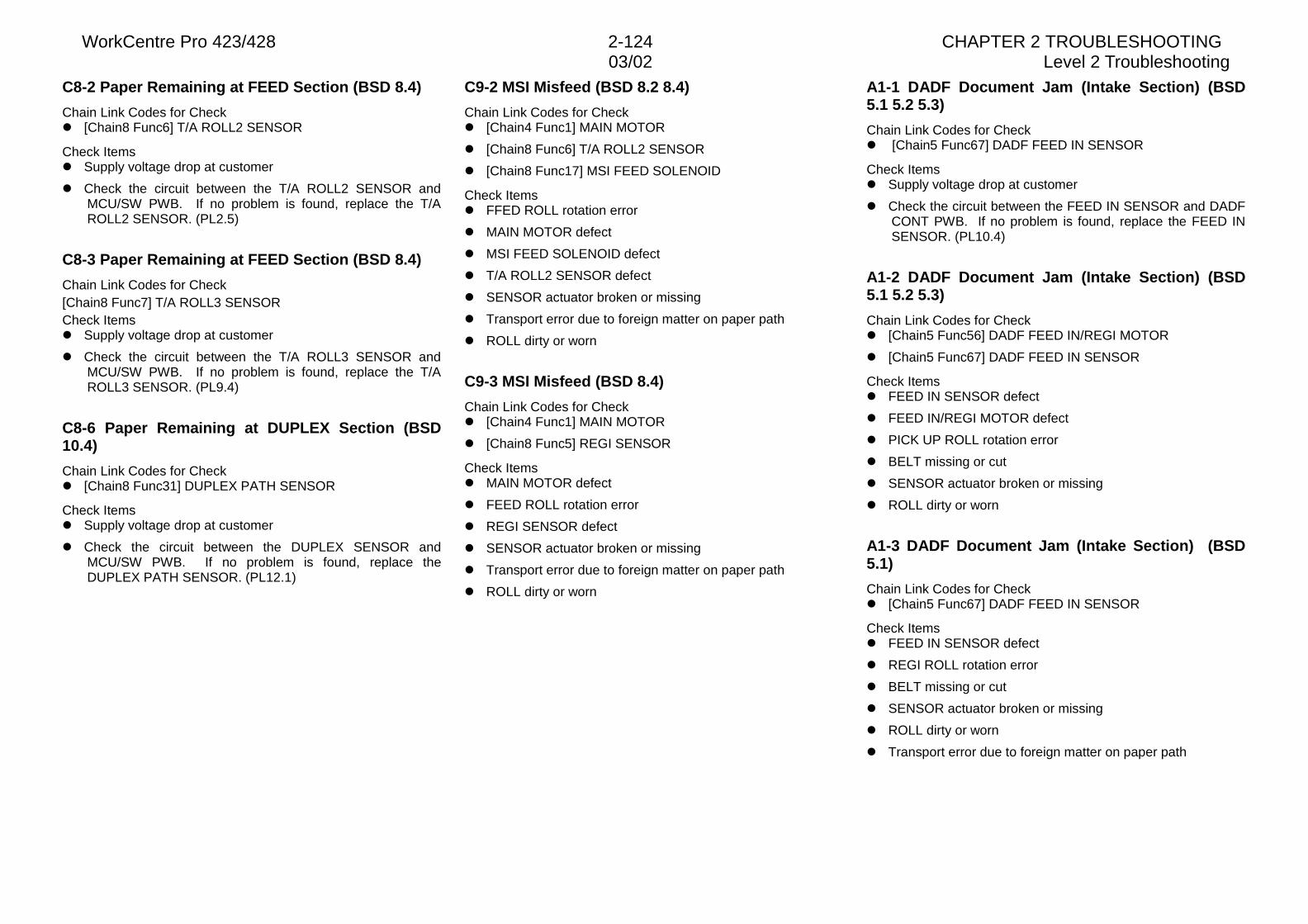
WorkCentre Pro 423/428 2-124 CHAPTER 2 TROUBLESHOOTING03/02 Level 2 Troubleshooting
C8-2 Paper Remaining at FEED Section (BSD 8.4)
Chain Link Codes for Checkl [Chain8 Func6] T/A ROLL2 SENSOR
Check Itemsl Supply voltage drop at customer
l Check the circuit between the T/A ROLL2 SENSOR andMCU/SW PWB. If no problem is found, replace the T/AROLL2 SENSOR. (PL2.5)
C8-3 Paper Remaining at FEED Section (BSD 8.4)
Chain Link Codes for Check[Chain8 Func7] T/A ROLL3 SENSORCheck Itemsl Supply voltage drop at customer
l Check the circuit between the T/A ROLL3 SENSOR andMCU/SW PWB. If no problem is found, replace the T/AROLL3 SENSOR. (PL9.4)
C8-6 Paper Remaining at DUPLEX Section (BSD10.4)
Chain Link Codes for Checkl [Chain8 Func31] DUPLEX PATH SENSOR
Check Itemsl Supply voltage drop at customer
l Check the circuit between the DUPLEX SENSOR andMCU/SW PWB. If no problem is found, replace theDUPLEX PATH SENSOR. (PL12.1)
C9-2 MSI Misfeed (BSD 8.2 8.4)
Chain Link Codes for Checkl [Chain4 Func1] MAIN MOTOR
l [Chain8 Func6] T/A ROLL2 SENSOR
l [Chain8 Func17] MSI FEED SOLENOID
Check Itemsl FFED ROLL rotation error
l MAIN MOTOR defect
l MSI FEED SOLENOID defect
l T/A ROLL2 SENSOR defect
l SENSOR actuator broken or missing
l Transport error due to foreign matter on paper path
l ROLL dirty or worn
C9-3 MSI Misfeed (BSD 8.4)
Chain Link Codes for Checkl [Chain4 Func1] MAIN MOTOR
l [Chain8 Func5] REGI SENSOR
Check Itemsl MAIN MOTOR defect
l FEED ROLL rotation error
l REGI SENSOR defect
l SENSOR actuator broken or missing
l Transport error due to foreign matter on paper path
l ROLL dirty or worn
A1-1 DADF Document Jam (Intake Section) (BSD5.1 5.2 5.3)
Chain Link Codes for Checkl [Chain5 Func67] DADF FEED IN SENSOR
Check Itemsl Supply voltage drop at customer
l Check the circuit between the FEED IN SENSOR and DADFCONT PWB. If no problem is found, replace the FEED INSENSOR. (PL10.4)
A1-2 DADF Document Jam (Intake Section) (BSD5.1 5.2 5.3)
Chain Link Codes for Checkl [Chain5 Func56] DADF FEED IN/REGI MOTOR
l [Chain5 Func67] DADF FEED IN SENSOR
Check Itemsl FEED IN SENSOR defect
l FEED IN/REGI MOTOR defect
l PICK UP ROLL rotation error
l BELT missing or cut
l SENSOR actuator broken or missing
l ROLL dirty or worn
A1-3 DADF Document Jam (Intake Section) (BSD5.1)
Chain Link Codes for Checkl [Chain5 Func67] DADF FEED IN SENSOR
Check Itemsl FEED IN SENSOR defect
l REGI ROLL rotation error
l BELT missing or cut
l SENSOR actuator broken or missing
l ROLL dirty or worn
l Transport error due to foreign matter on paper path
03/02 Level 2 TroubleshootingWorkCentre Pro 423/428 2-125 CHAPTER 2 TROUBLESHOOTING
A2-1 DADF Document Jam (Regi. Section) (BSD5.4)
Chain Link Codes for Checkl [Chain5 Func65] DADF READ SENSOR
l [Chain5 Func69] DADF REGI SENSOR
Check Itemsl Supply voltage drop at customer
l Check the circuit between each Sensor and DADF CONTPWB. If no problem is found, replace the READSENSOR(PL10.6). If the problem is not cleared, replace theREGI SENSOR.(PL10.6)
A2-2 DADF Document Jam (Regi. Section) (BSD 5.35.4)
Chain Link Codes for Checkl [Chain5 Func57] DADF FEED IN/REGI MOTOR
l [Chain5 Func65] DADF READ SENSOR
l [Chain5 Func69] DADF REGI SENSOR
Check Itemsl READ SENSOR defect
l REGI SENSOR defect
l TRANSPORT ROLL rotation error
l REGI ROLL rotation error
l FEED IN/REGI MOTOR defect
l BELT missing or cut
l SENSOR actuator broken or missing
l ROLL dirty or worn
A2-3 DADF Document Jam (Regi. Section) (BSD 5.35.4)
Chain Link Codes for Checkl [Chain5 Func51] DADF READ EXIT MOTOR
l [Chain5 Func57] DADF FEED IN/REGI MOTOR
l [Chain5 Func65] DADF READ SENSOR
l [Chain5 Func69] DADF REGI SENSOR
Check Itemsl READ SENSOR defect
l REGI SENSOR defect
l TRANSPORT ROLL rotation error
l REGI ROLL rotation error
l INVERT/EXIT ROLL rotation error
l READ EXIT MOTOR
l FEED IN/REGI MOTOR defect
l BELT missing or cut
l SENSOR actuator broken or missing
l ROLL dirty or worn
A2-4 DADF Document Jam (Regi. Section) (BSD 5.35.4)
Chain Link Codes for Checkl [Chain5 Func51] DADF READ EXIT MOTOR
l [Chain5 Func57] DADF FEED IN/REGI MOTOR
l [Chain5 Func66] DADF EXIT/REVERSE SENSOR
Check Itemsl EXIT/REVERSE SENSOR defect
l READ ROLL rotation error
l TRANSPORT ROLL rotation error
l BELT missing or cut
l SENSOR actuator broken or missing
l ROLL dirty or worn
l Transport error due to foreign matter on paper path
A3-1 DADF Document Jam (Ejection Section) (BSD5.4)
Chain Link Codes for Checkl [Chain5 Func66] DADF EXIT/REVERSE SENSOR
Check Itemsl Supply voltage drop at customer
l Check the circuit between EXIT/REVERSE SENSOR andDADF CONT PWB. If no problem is found, replace theEXIT/ REVERSE SENSOR. (PL10.6)
A3-2 DADF Document Jam (Ejection Section) (BSD5.3 5.4)
Chain Link Codes for Checkl [Chain5 Func51] DADF READ EXIT MOTOR
l [Chain5 Func57] DADF FEED IN/REGI MOTOR
l [Chain5 Func69] DADF REGI SENSOR
l [Chain5 Func81] DADF EXIT/REVERSE SOLENOID
Check Itemsl REGI SENSOR defect
l FLAP GUIDE operation error
l EXIT/REVERSE SOLENOID operation error
l INVERT EXIT ROLL rotation error
l FEED IN ROLL rotation error
l READ EXIT MOTOR defect
l FEED IN/REGI MOTOR
l BELT missing or cut
l SENSOR actuator broken or missing
l ROLL dirty or worn
WorkCentre Pro 423/428 2-126 CHAPTER 2 TROUBLESHOOTING03/02 Level 2 Troubleshooting
A3-3 DADF Document Jam (Ejection Section)
Chain Link Codes for Checkl [Chain5 Func51] DADF READ EXIT MOTOR
l [Chain5 Func66] DADF EXIT/REVERSE SENSOR
Check Itemsl EXIT/REVERSE SENSOR defect
l TRANSPORT rotation error
l READ EXIT MOTOR defect
l SENSOR actuator broken or missing
l ROLL dirty or worn
A5-1 DADF Interlock Open (BSD 1.7B)
Open the DADF TOP COVER and press the actuator of theDADF INTERLOCK SW with a screwdriver.Does the error display disappear?Y N
Close the DADF TOP COVER. Is the voltage +24 VDCbetween the DADF CONT PWB J2-2(+) and GND(-)?Y N
Is the voltage +24 VDC between the DADF CONTPWB J2-1(+) and GND(-)?Y N
Is the voltage +24 VDC between the DADFCONT PWB J1-1(+) and GND(-)?Y N
Perform +24VDC FIP.Replace the DADF CONT PWB. (PLXX.X)
Is the voltage +24 VDC between the DADFINTERLOCK SW J32-1(+) and GND(-)?Y N
Check between the DADF INTERLOCK SWJ32-1 and DADF CONT PWB J2-1 for an openwire or poor contact.
Is the voltage +24 VDC between the DADFINTERLOCK SW J32-2(+) and GND(-)?Y N
Replace the DADF INTERLOCK SW. (PLXX.X)Check between the DADF INTERLOCK SW J32-2and DADF CONT PWB J2-2 for an open wire or poorcontact.
Replace the DADF CONT PWB. (PLXX.X)Check the DADF TOP COVER actuator for damage ormisalignment.
F4-11 FINISHER IN SENSOR Jam (BSD 12.3 12.5)
Chain Link Codes for Checkl Chain12 Func1] FINISHER IN SENSOR
l [Chain12 Func30] FINISHER REVERSE MOTOR
l [Chain12 Func32] FINISHER FEED MOTOR
Check Itemsl FINISHER IN SENSOR defect
l FINISHER FEED MOTOR defect
l FEED ROLL rotation error
l FINISHER Invertion MOTOR defect
l REVERSE ROLL rotation error
l SENSOR actuator broken or missing
l ROLL dirty or worn
l Transport error due to foreign matter on paper path
F4-12 FINISHER IN SENSOR Jam (BSD 10.5 12.5)
Chain Link Codes for Checkl [Chain10 Func61] EXIT MOTOR
l [Chain12 Func1] FINISHER IN SENSOR
Check Itemsl EXIT MOTOR rotation error
l FACE UP EXIT ROLL rotation error
l FINISHER IN SENSOR defect
l SENSOR actuator broken or missing
l ROLL dirty or worn
l Transport error due to foreign matter on paper path
F4-16 FINISHER IN SENSOR Jam (BSD 12.5)
Chain Link Codes for Checkl [Chain12 Func1] FINISHER IN SENSOR
Check Itemsl Supply voltage drop at customer
l Check the circuit between the FINISHER IN SENSOR andFINISHER CONT PWB. If no problem is found, replace theFINISHER IN SENSOR. (PL13.11)
03/02 Level 2 TroubleshootingWorkCentre Pro 423/428 2-127 CHAPTER 2 TROUBLESHOOTING
F4-21 FINISHER REVERSE SENSOR Jam (BSD12.5)
Chain Link Codes for Checkl [Chain12 Func2] FINISHER REVERSE SENSOR
l [Chain12 Func21] FINISHER TRANSFER MOTOR
l [Chain12 Func31] FINISHER REVERSE MOTOR
Check Itemsl FINISHER REVERSE SENSOR defect
l FINISHER REVERSE MOTOR defect
l REVERSE ROLL rotation error
l FINISHER TRANSFER MOTOR defect
l TRANSFER ROLL rotation error
l SENSOR actuator broken or missing
l ROLL dirty or worn
l Transport error due to foreign matter on paper path
F4-22 FINISHER REVERSE SENSOR Jam (BSD12.5)
Chain Link Codes for Checkl [Chain12 Func2] FINISHER REVERSE SENSOR
l [Chain12 Func32] FINISHER FEED MOTOR
Check Itemsl FINISHER REVERSE SENSOR defect
l FINISHER FEED MOTOR defect
l FEED ROLL rotation error
l SENSOR actuator broken or missing
l ROLL dirty or worn
l Transport error due to foreign matter on paper path
F4-26 FINISHER REVERSE SENSOR Jam (BSD12.5)
Chain Link Codes for Checkl [Chain12 Func2] FINISHER REVERSE SENSOR
Check Itemsl Supply voltage drop at customer
l Check the circuit between the FINISHER REVERSESENSOR and FINISHER CONT PWB. If no problem isfound, replace the FINISHER REVERSE SENSOR.(PL13.15)
F4-31 FINISHER TIMING SENSOR Jam (BSD 12.6)
Chain Link Codes for Checkl [Chain12 Func3] FINISHER TIMING SENSOR
l [Chain12 Func21] FINISHER TRANSFER MOTOR
Check Itemsl FINISHER TIMING SENSOR defect
l FINISHER TRANSFER MOTOR defect
l TIMING ROLL rotation error
l EXIT ROLL rotation error
l TRANSFER BELT rotation error
l SENSOR actuator broken or missing
l ROLL dirty or worn
l BELT missing or cut
l Transport error due to foreign matter on paper path
F4-32 FINISHER TIMING SENSOR Jam (BSD 12.6)
Chain Link Codes for Checkl [Chain12 Func3] FINISHER TIMING SENSOR
l [Chain12 Func21] FINISHER TRANSFER MOTOR
Check Itemsl FINISHER TIMING SENSOR defect
l FINISHER TRANSFER MOTOR defect
l TRANSFER ROLL rotation error
l SENSOR actuator broken or missing
l ROLL dirty or worn
l Transport error due to foreign matter on paper path
WorkCentre Pro 423/428 2-128 CHAPTER 2 TROUBLESHOOTING03/02 Level 2 Troubleshooting
F4-36 FINISHER TIMING SENSOR Jam (BSD 12.6)
Chain Link Codes for Checkl [Chain12 Func3] FINISHER TIMING SENSOR
Check Itemsl Supply voltage drop at customer
l Check the circuit between the FINISHER TIMING SENSORand FINISHER CONT PWB. If no problem is found, replacethe FINISHER TIMING SENSOR. (PL13.8)
F4-41 FINISHER EXIT SENSOR Jam (BSD 12.7)
Chain Link Codes for Checkl [Chain12 Func4] FINISHER EXIT SENSOR
l [Chain12 Func21] FINISHER TRANSFER MOTOR
Check Itemsl FINISHER EXIT SENSOR defect
l FINISHER TRANSFER MOTOR defect
l EXIT ROLL rotation error
l TRANSFER BELT rotation error
l SENSOR actuator broken or missing
l ROLL dirty or worn
l BELT missing or cut
F4-42 FINISHER EXIT SENSOR Jam (BSD 12.7)
Chain Link Codes for Checkl [Chain12 Func4] FINISHER EXIT SENSOR
l [Chain12 Func21] FINISHER Transport MOTOR
Check Itemsl FINISHER EXIT SENSOR defect
l FINISHER Transport MOTOR defect
l EXIT ROLL rotation error
l Transport BELT rotation error
l SENSOR actuator broken or missing
l ROLL dirty or worn
l BELT missing or cut
l Transport error due to foreign matter on paper path
F4-46 FINISHER EXIT SENSOR Jam (BSD 12.7)
Chain Link Codes for Checkl [Chain12 Func4] FINISHER EXIT SENSOR
Check Itemsl Supply voltage drop at customer
l Check the circuit between the FINISHER EXIT SENSOR andFINISHER CONT PWB. If no problem is found, replace theFINISHER EXIT SENSOR. (PL13.12)
F7-1 FINISHER Interlock Open (BSD 12.2)
Close the L/H LOWER COVER and L/H UPPERE COVER.Does the error display disappear?Y N
Open the L/H LOWER COVER and press the actuator ofthe PAPER PATH COVER SENSOR with a screwdriver.Does the error display disappear?Y N
Perform the General-purpose transmittion sensor FIP.Check that the Cover is installed securely.
End of work.
F7-2 FINISHER Interlock Open (BSD 12.1)
Close the FRONT DOOR.Does the error display disappear?Y N
Remove the FRONT COVER and press the actuator of theSTAPLER COVER SW by hand.Does the error display disappear?Y N
Reinstall the FRONT COVER and close the FRONTDOOR.Is the voltage + 24 VDC between the FINISHERCONT PWB CN3-3(+) and GND(-)?Y N
Is the voltage + 24 VDC between the FINISHERCONT PWB CN3-1(+) and GND(-)?Y N
Is the voltage + 24 VDC between the FINI-SHER CONT PWB CN1-1(+) and GND(-)?Y N
Perform +24VDC FIP.Replace the FINISHER CONTPWB.(PL13.16)
Keep pressing the actuator of the STAPLERCOVER SW. Is the voltage +24 VDC betweenthe STAPLER COVER SW connector and GND?Y N
Replace the STAPLER COVERSW.(PL13.2)
Check between the STAPLER COVER SW andINISHER CONT PWB for an open wire or poorcontact.
Replace the FINISHER CONT PWB. (PL13.16)Check the FRONT DOOR actuator for damage.
End of work.
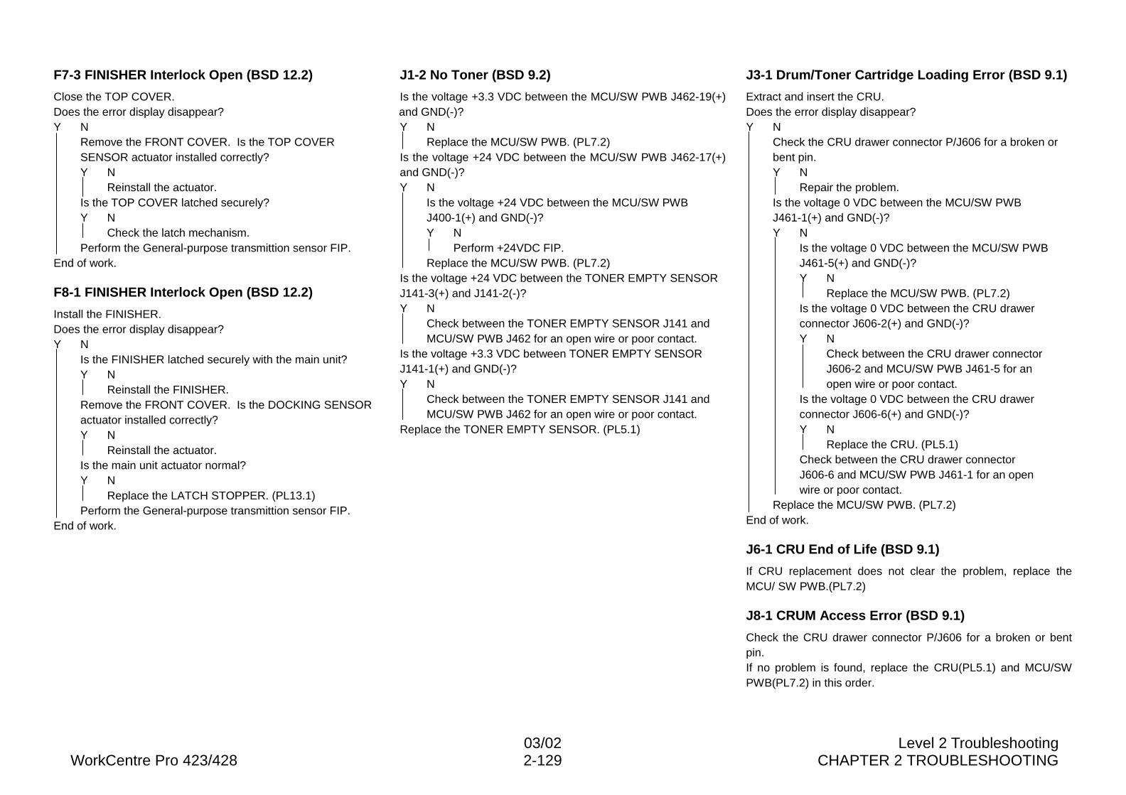
03/02 Level 2 TroubleshootingWorkCentre Pro 423/428 2-129 CHAPTER 2 TROUBLESHOOTING
F7-3 FINISHER Interlock Open (BSD 12.2)
Close the TOP COVER.Does the error display disappear?Y N
Remove the FRONT COVER. Is the TOP COVERSENSOR actuator installed correctly?Y N
Reinstall the actuator.Is the TOP COVER latched securely?Y N
Check the latch mechanism.Perform the General-purpose transmittion sensor FIP.
End of work.
F8-1 FINISHER Interlock Open (BSD 12.2)
Install the FINISHER.Does the error display disappear?Y N
Is the FINISHER latched securely with the main unit?Y N
Reinstall the FINISHER.Remove the FRONT COVER. Is the DOCKING SENSORactuator installed correctly?Y N
Reinstall the actuator.Is the main unit actuator normal?Y N
Replace the LATCH STOPPER. (PL13.1)Perform the General-purpose transmittion sensor FIP.
End of work.
J1-2 No Toner (BSD 9.2)
Is the voltage +3.3 VDC between the MCU/SW PWB J462-19(+)and GND(-)?Y N
Replace the MCU/SW PWB. (PL7.2)Is the voltage +24 VDC between the MCU/SW PWB J462-17(+)and GND(-)?Y N
Is the voltage +24 VDC between the MCU/SW PWBJ400-1(+) and GND(-)?Y N
Perform +24VDC FIP.Replace the MCU/SW PWB. (PL7.2)
Is the voltage +24 VDC between the TONER EMPTY SENSORJ141-3(+) and J141-2(-)?Y N
Check between the TONER EMPTY SENSOR J141 andMCU/SW PWB J462 for an open wire or poor contact.
Is the voltage +3.3 VDC between TONER EMPTY SENSORJ141-1(+) and GND(-)?Y N
Check between the TONER EMPTY SENSOR J141 andMCU/SW PWB J462 for an open wire or poor contact.
Replace the TONER EMPTY SENSOR. (PL5.1)
J3-1 Drum/Toner Cartridge Loading Error (BSD 9.1)
Extract and insert the CRU.Does the error display disappear?Y N
Check the CRU drawer connector P/J606 for a broken orbent pin.Y N
Repair the problem.Is the voltage 0 VDC between the MCU/SW PWBJ461-1(+) and GND(-)?Y N
Is the voltage 0 VDC between the MCU/SW PWBJ461-5(+) and GND(-)?Y N
Replace the MCU/SW PWB. (PL7.2)Is the voltage 0 VDC between the CRU drawerconnector J606-2(+) and GND(-)?Y N
Check between the CRU drawer connectorJ606-2 and MCU/SW PWB J461-5 for anopen wire or poor contact.
Is the voltage 0 VDC between the CRU drawerconnector J606-6(+) and GND(-)?Y N
Replace the CRU. (PL5.1)Check between the CRU drawer connectorJ606-6 and MCU/SW PWB J461-1 for an openwire or poor contact.
Replace the MCU/SW PWB. (PL7.2)End of work.
J6-1 CRU End of Life (BSD 9.1)
If CRU replacement does not clear the problem, replace theMCU/ SW PWB.(PL7.2)
J8-1 CRUM Access Error (BSD 9.1)
Check the CRU drawer connector P/J606 for a broken or bentpin.If no problem is found, replace the CRU(PL5.1) and MCU/SWPWB(PL7.2) in this order.
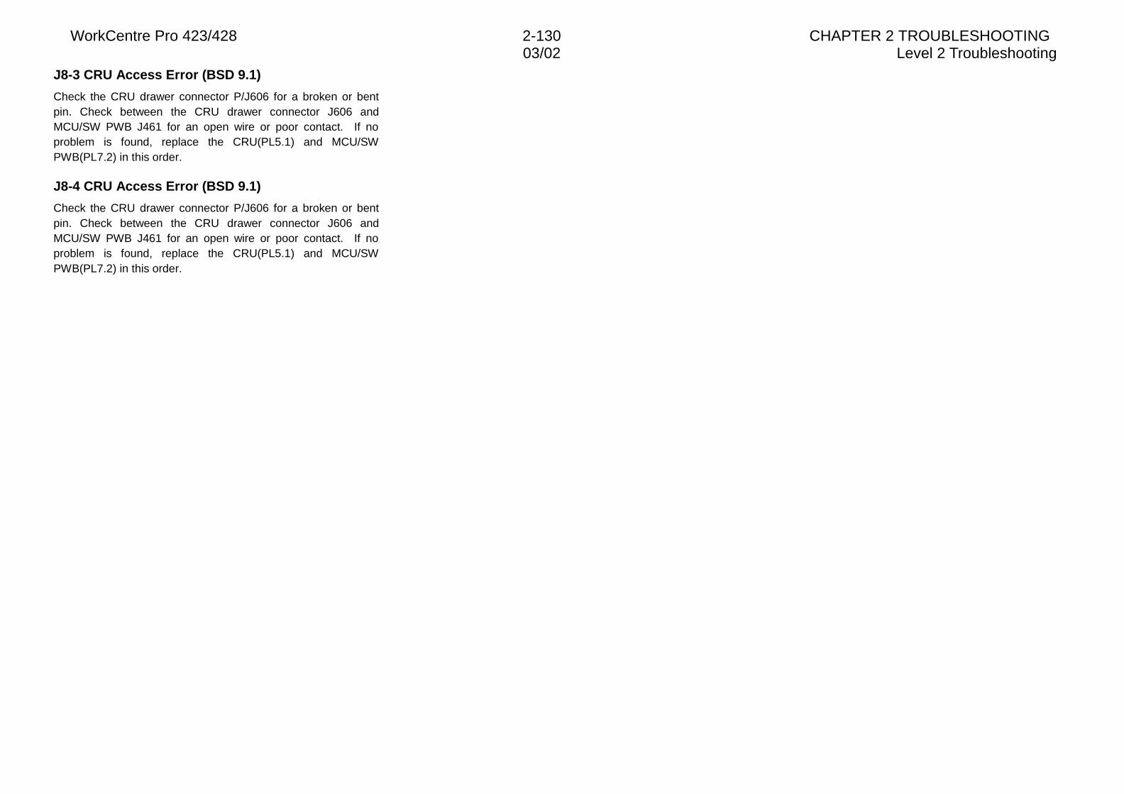
WorkCentre Pro 423/428 2-130 CHAPTER 2 TROUBLESHOOTING03/02 Level 2 Troubleshooting
J8-3 CRU Access Error (BSD 9.1)
Check the CRU drawer connector P/J606 for a broken or bentpin. Check between the CRU drawer connector J606 andMCU/SW PWB J461 for an open wire or poor contact. If noproblem is found, replace the CRU(PL5.1) and MCU/SWPWB(PL7.2) in this order.
J8-4 CRU Access Error (BSD 9.1)
Check the CRU drawer connector P/J606 for a broken or bentpin. Check between the CRU drawer connector J606 andMCU/SW PWB J461 for an open wire or poor contact. If noproblem is found, replace the CRU(PL5.1) and MCU/SWPWB(PL7.2) in this order.
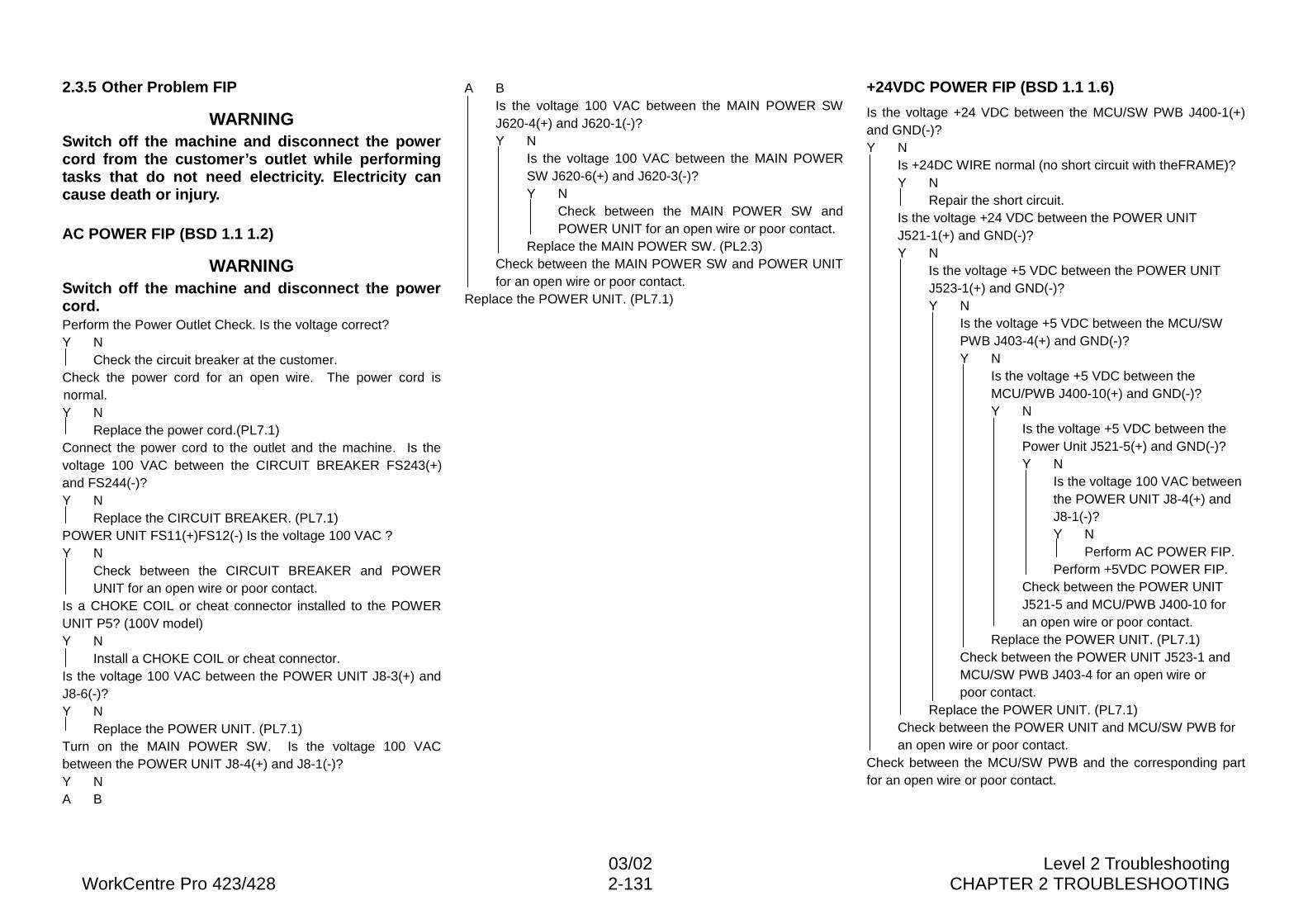
03/02 Level 2 TroubleshootingWorkCentre Pro 423/428 2-131 CHAPTER 2 TROUBLESHOOTING
2.3.5 Other Problem FIP
WARNINGSwitch off the machine and disconnect the powercord from the customer’s outlet while performingtasks that do not need electricity. Electricity cancause death or injury.
AC POWER FIP (BSD 1.1 1.2)
WARNINGSwitch off the machine and disconnect the powercord.Perform the Power Outlet Check. Is the voltage correct?Y N
Check the circuit breaker at the customer.Check the power cord for an open wire. The power cord isnormal.Y N
Replace the power cord.(PL7.1)Connect the power cord to the outlet and the machine. Is thevoltage 100 VAC between the CIRCUIT BREAKER FS243(+)and FS244(-)?Y N
Replace the CIRCUIT BREAKER. (PL7.1)POWER UNIT FS11(+)FS12(-) Is the voltage 100 VAC ?Y N
Check between the CIRCUIT BREAKER and POWERUNIT for an open wire or poor contact.
Is a CHOKE COIL or cheat connector installed to the POWERUNIT P5? (100V model)Y N
Install a CHOKE COIL or cheat connector.Is the voltage 100 VAC between the POWER UNIT J8-3(+) andJ8-6(-)?Y N
Replace the POWER UNIT. (PL7.1)Turn on the MAIN POWER SW. Is the voltage 100 VACbetween the POWER UNIT J8-4(+) and J8-1(-)?Y NA B
A BIs the voltage 100 VAC between the MAIN POWER SWJ620-4(+) and J620-1(-)?Y N
Is the voltage 100 VAC between the MAIN POWERSW J620-6(+) and J620-3(-)?Y N
Check between the MAIN POWER SW andPOWER UNIT for an open wire or poor contact.
Replace the MAIN POWER SW. (PL2.3)Check between the MAIN POWER SW and POWER UNITfor an open wire or poor contact.
Replace the POWER UNIT. (PL7.1)
+24VDC POWER FIP (BSD 1.1 1.6)
Is the voltage +24 VDC between the MCU/SW PWB J400-1(+)and GND(-)?Y N
Is +24DC WIRE normal (no short circuit with theFRAME)?Y N
Repair the short circuit.Is the voltage +24 VDC between the POWER UNITJ521-1(+) and GND(-)?Y N
Is the voltage +5 VDC between the POWER UNITJ523-1(+) and GND(-)?Y N
Is the voltage +5 VDC between the MCU/SWPWB J403-4(+) and GND(-)?Y N
Is the voltage +5 VDC between theMCU/PWB J400-10(+) and GND(-)?Y N
Is the voltage +5 VDC between thePower Unit J521-5(+) and GND(-)?Y N
Is the voltage 100 VAC betweenthe POWER UNIT J8-4(+) andJ8-1(-)?Y N
Perform AC POWER FIP.Perform +5VDC POWER FIP.
Check between the POWER UNITJ521-5 and MCU/PWB J400-10 foran open wire or poor contact.
Replace the POWER UNIT. (PL7.1)Check between the POWER UNIT J523-1 andMCU/SW PWB J403-4 for an open wire orpoor contact.
Replace the POWER UNIT. (PL7.1)Check between the POWER UNIT and MCU/SW PWB foran open wire or poor contact.
Check between the MCU/SW PWB and the corresponding partfor an open wire or poor contact.
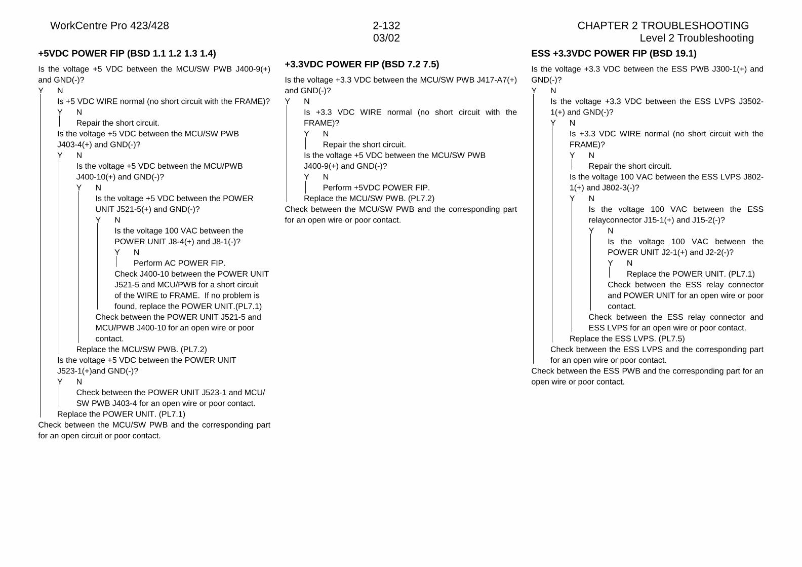
WorkCentre Pro 423/428 2-132 CHAPTER 2 TROUBLESHOOTING03/02 Level 2 Troubleshooting
+5VDC POWER FIP (BSD 1.1 1.2 1.3 1.4)
Is the voltage +5 VDC between the MCU/SW PWB J400-9(+)and GND(-)?Y N
Is +5 VDC WIRE normal (no short circuit with the FRAME)?Y N
Repair the short circuit.Is the voltage +5 VDC between the MCU/SW PWBJ403-4(+) and GND(-)?Y N
Is the voltage +5 VDC between the MCU/PWBJ400-10(+) and GND(-)?Y N
Is the voltage +5 VDC between the POWERUNIT J521-5(+) and GND(-)?Y N
Is the voltage 100 VAC between thePOWER UNIT J8-4(+) and J8-1(-)?Y N
Perform AC POWER FIP.Check J400-10 between the POWER UNITJ521-5 and MCU/PWB for a short circuitof the WIRE to FRAME. If no problem isfound, replace the POWER UNIT.(PL7.1)
Check between the POWER UNIT J521-5 andMCU/PWB J400-10 for an open wire or poorcontact.
Replace the MCU/SW PWB. (PL7.2)Is the voltage +5 VDC between the POWER UNITJ523-1(+)and GND(-)?Y N
Check between the POWER UNIT J523-1 and MCU/SW PWB J403-4 for an open wire or poor contact.
Replace the POWER UNIT. (PL7.1)Check between the MCU/SW PWB and the corresponding partfor an open circuit or poor contact.
+3.3VDC POWER FIP (BSD 7.2 7.5)
Is the voltage +3.3 VDC between the MCU/SW PWB J417-A7(+)and GND(-)?Y N
Is +3.3 VDC WIRE normal (no short circuit with theFRAME)?Y N
Repair the short circuit.Is the voltage +5 VDC between the MCU/SW PWBJ400-9(+) and GND(-)?Y N
Perform +5VDC POWER FIP.Replace the MCU/SW PWB. (PL7.2)
Check between the MCU/SW PWB and the corresponding partfor an open wire or poor contact.
ESS +3.3VDC POWER FIP (BSD 19.1)
Is the voltage +3.3 VDC between the ESS PWB J300-1(+) andGND(-)?Y N
Is the voltage +3.3 VDC between the ESS LVPS J3502-1(+) and GND(-)?Y N
Is +3.3 VDC WIRE normal (no short circuit with theFRAME)?Y N
Repair the short circuit.Is the voltage 100 VAC between the ESS LVPS J802-1(+) and J802-3(-)?Y N
Is the voltage 100 VAC between the ESSrelayconnector J15-1(+) and J15-2(-)?Y N
Is the voltage 100 VAC between thePOWER UNIT J2-1(+) and J2-2(-)?Y N
Replace the POWER UNIT. (PL7.1)Check between the ESS relay connectorand POWER UNIT for an open wire or poorcontact.
Check between the ESS relay connector andESS LVPS for an open wire or poor contact.
Replace the ESS LVPS. (PL7.5)Check between the ESS LVPS and the corresponding partfor an open wire or poor contact.
Check between the ESS PWB and the corresponding part for anopen wire or poor contact.
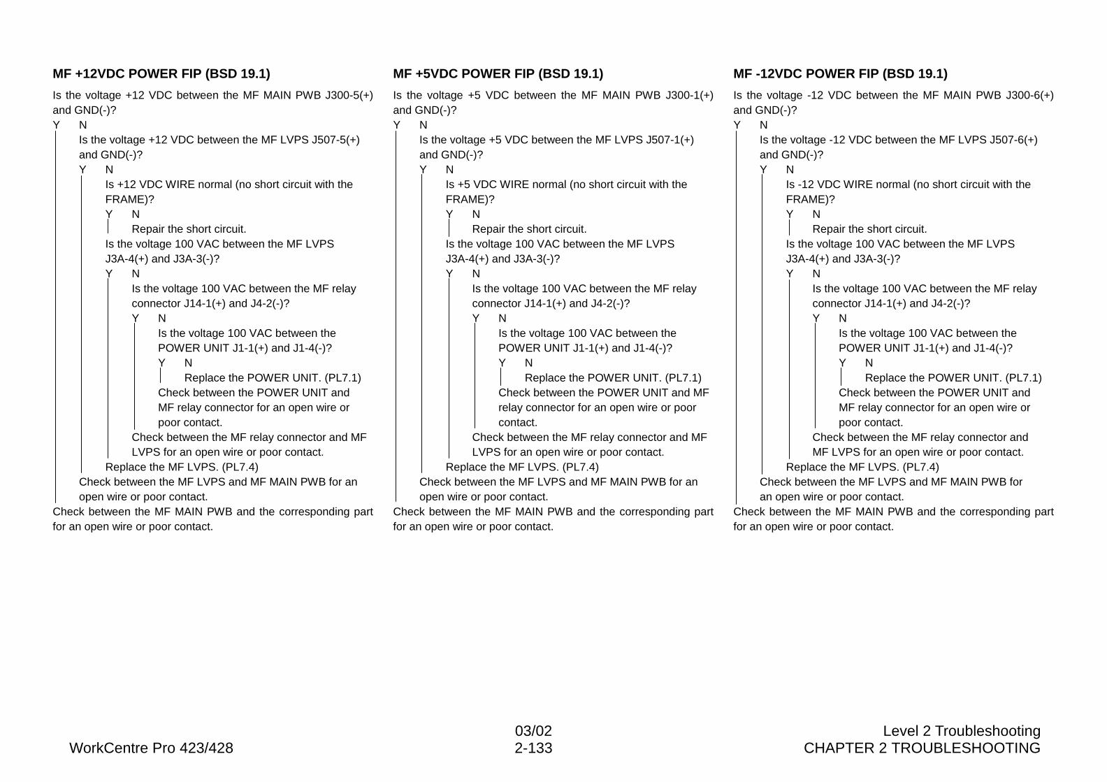
03/02 Level 2 TroubleshootingWorkCentre Pro 423/428 2-133 CHAPTER 2 TROUBLESHOOTING
MF +12VDC POWER FIP (BSD 19.1)
Is the voltage +12 VDC between the MF MAIN PWB J300-5(+)and GND(-)?Y N
Is the voltage +12 VDC between the MF LVPS J507-5(+)and GND(-)?Y N
Is +12 VDC WIRE normal (no short circuit with theFRAME)?Y N
Repair the short circuit.Is the voltage 100 VAC between the MF LVPSJ3A-4(+) and J3A-3(-)?Y N
Is the voltage 100 VAC between the MF relayconnector J14-1(+) and J4-2(-)?Y N
Is the voltage 100 VAC between thePOWER UNIT J1-1(+) and J1-4(-)?Y N
Replace the POWER UNIT. (PL7.1)Check between the POWER UNIT andMF relay connector for an open wire orpoor contact.
Check between the MF relay connector and MFLVPS for an open wire or poor contact.
Replace the MF LVPS. (PL7.4)Check between the MF LVPS and MF MAIN PWB for anopen wire or poor contact.
Check between the MF MAIN PWB and the corresponding partfor an open wire or poor contact.
MF +5VDC POWER FIP (BSD 19.1)
Is the voltage +5 VDC between the MF MAIN PWB J300-1(+)and GND(-)?Y N
Is the voltage +5 VDC between the MF LVPS J507-1(+)and GND(-)?Y N
Is +5 VDC WIRE normal (no short circuit with theFRAME)?Y N
Repair the short circuit.Is the voltage 100 VAC between the MF LVPSJ3A-4(+) and J3A-3(-)?Y N
Is the voltage 100 VAC between the MF relayconnector J14-1(+) and J4-2(-)?Y N
Is the voltage 100 VAC between thePOWER UNIT J1-1(+) and J1-4(-)?Y N
Replace the POWER UNIT. (PL7.1)Check between the POWER UNIT and MFrelay connector for an open wire or poorcontact.
Check between the MF relay connector and MFLVPS for an open wire or poor contact.
Replace the MF LVPS. (PL7.4)Check between the MF LVPS and MF MAIN PWB for anopen wire or poor contact.
Check between the MF MAIN PWB and the corresponding partfor an open wire or poor contact.
MF -12VDC POWER FIP (BSD 19.1)
Is the voltage -12 VDC between the MF MAIN PWB J300-6(+)and GND(-)?Y N
Is the voltage -12 VDC between the MF LVPS J507-6(+)and GND(-)?Y N
Is -12 VDC WIRE normal (no short circuit with theFRAME)?Y N
Repair the short circuit.Is the voltage 100 VAC between the MF LVPSJ3A-4(+) and J3A-3(-)?Y N
Is the voltage 100 VAC between the MF relayconnector J14-1(+) and J4-2(-)?Y N
Is the voltage 100 VAC between thePOWER UNIT J1-1(+) and J1-4(-)?Y N
Replace the POWER UNIT. (PL7.1)Check between the POWER UNIT andMF relay connector for an open wire orpoor contact.
Check between the MF relay connector andMF LVPS for an open wire or poor contact.
Replace the MF LVPS. (PL7.4)Check between the MF LVPS and MF MAIN PWB foran open wire or poor contact.
Check between the MF MAIN PWB and the corresponding partfor an open wire or poor contact.
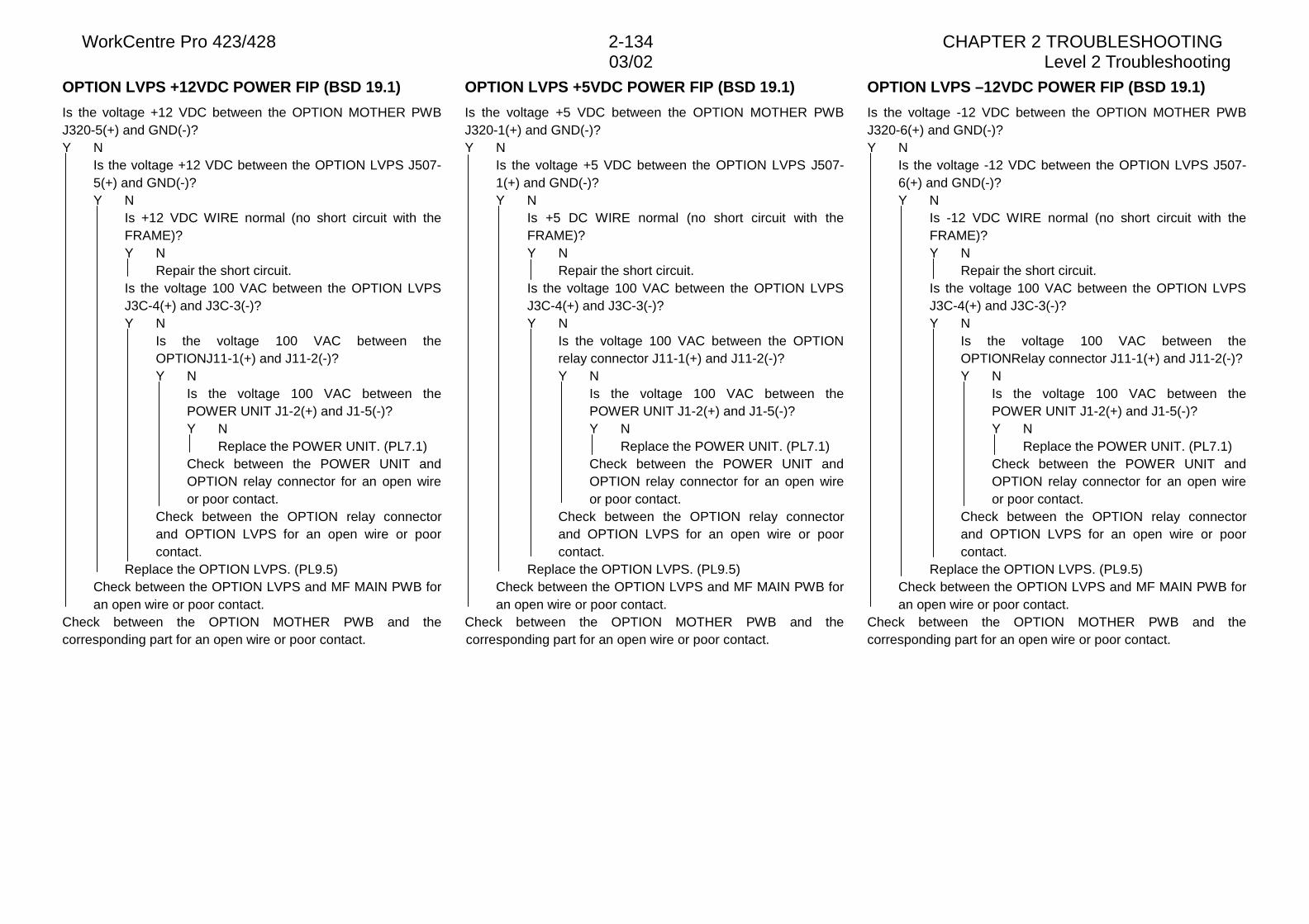
WorkCentre Pro 423/428 2-134 CHAPTER 2 TROUBLESHOOTING03/02 Level 2 Troubleshooting
OPTION LVPS +12VDC POWER FIP (BSD 19.1)
Is the voltage +12 VDC between the OPTION MOTHER PWBJ320-5(+) and GND(-)?Y N
Is the voltage +12 VDC between the OPTION LVPS J507-5(+) and GND(-)?Y N
Is +12 VDC WIRE normal (no short circuit with theFRAME)?Y N
Repair the short circuit.Is the voltage 100 VAC between the OPTION LVPSJ3C-4(+) and J3C-3(-)?Y N
Is the voltage 100 VAC between theOPTIONJ11-1(+) and J11-2(-)?Y N
Is the voltage 100 VAC between thePOWER UNIT J1-2(+) and J1-5(-)?Y N
Replace the POWER UNIT. (PL7.1)Check between the POWER UNIT andOPTION relay connector for an open wireor poor contact.
Check between the OPTION relay connectorand OPTION LVPS for an open wire or poorcontact.
Replace the OPTION LVPS. (PL9.5)Check between the OPTION LVPS and MF MAIN PWB foran open wire or poor contact.
Check between the OPTION MOTHER PWB and thecorresponding part for an open wire or poor contact.
OPTION LVPS +5VDC POWER FIP (BSD 19.1)
Is the voltage +5 VDC between the OPTION MOTHER PWBJ320-1(+) and GND(-)?Y N
Is the voltage +5 VDC between the OPTION LVPS J507-1(+) and GND(-)?Y N
Is +5 DC WIRE normal (no short circuit with theFRAME)?Y N
Repair the short circuit.Is the voltage 100 VAC between the OPTION LVPSJ3C-4(+) and J3C-3(-)?Y N
Is the voltage 100 VAC between the OPTIONrelay connector J11-1(+) and J11-2(-)?Y N
Is the voltage 100 VAC between thePOWER UNIT J1-2(+) and J1-5(-)?Y N
Replace the POWER UNIT. (PL7.1)Check between the POWER UNIT andOPTION relay connector for an open wireor poor contact.
Check between the OPTION relay connectorand OPTION LVPS for an open wire or poorcontact.
Replace the OPTION LVPS. (PL9.5)Check between the OPTION LVPS and MF MAIN PWB foran open wire or poor contact.
Check between the OPTION MOTHER PWB and thecorresponding part for an open wire or poor contact.
OPTION LVPS –12VDC POWER FIP (BSD 19.1)
Is the voltage -12 VDC between the OPTION MOTHER PWBJ320-6(+) and GND(-)?Y N
Is the voltage -12 VDC between the OPTION LVPS J507-6(+) and GND(-)?Y N
Is -12 VDC WIRE normal (no short circuit with theFRAME)?Y N
Repair the short circuit.Is the voltage 100 VAC between the OPTION LVPSJ3C-4(+) and J3C-3(-)?Y N
Is the voltage 100 VAC between theOPTIONRelay connector J11-1(+) and J11-2(-)?Y N
Is the voltage 100 VAC between thePOWER UNIT J1-2(+) and J1-5(-)?Y N
Replace the POWER UNIT. (PL7.1)Check between the POWER UNIT andOPTION relay connector for an open wireor poor contact.
Check between the OPTION relay connectorand OPTION LVPS for an open wire or poorcontact.
Replace the OPTION LVPS. (PL9.5)Check between the OPTION LVPS and MF MAIN PWB foran open wire or poor contact.
Check between the OPTION MOTHER PWB and thecorresponding part for an open wire or poor contact.

03/02 Level 2 TroubleshootingWorkCentre Pro 423/428 2-135 CHAPTER 2 TROUBLESHOOTING
FINISHER LVPS +24VDC POWER FIP (BSD 12.1)
Is the voltage +24 VDC between the FINISHER CONT PWBCN1-1(+) and GND(-)?Y N
Is the voltage +24 VDC between the FINISHER LVPSCN51-1(+) and GND(-)?Y N
Is +24VDC WIRE normal (no short circuit with theFRAME)?Y N
Repair the short circuit.Is the voltage 100 VAC between the FINISHER LVPSCN1-1(+) and CN1-3(-)?Y N
Is the voltage 100 VAC between the FINISHERrelay connector J13-1(+) and J13-2(-)?Y N
Is the voltage 100 VAC between thePOWER UNIT J3-1(+) and J3-3(-)?Y N
Replace the POWER UNIT. (PL7.1)Check between the POWER UNIT andFINISHER relay connector for an openwireor poor contact.
Check between the FINISHER relay connectorand FINISHER LVPS for an open wireor poorcontact.
Replace the FINISHER LVPS. (PL13.16)Check between the FINISHER LVPS and FINISHER CONTPWB for an open wire or poor contact.
Check between the FINISHER CONT PWB and thecorresponding part for an open wire or poor contact.
FINISHER LVPS +5VDC POWER FIP (BSD 12.1)
Is the voltage +5 VDC between the FINISHER CONT PWBCN17-1(+) and GND(-)?Y N
Is the voltage +24 VDC between the FINISHER CONTPWB CN1-1(+) and GND(-)?Y N
Perform +24VDC POWER FIP.Is +5 VDC WIRE normal (no short circuit with the FRAME)?Y N
Repair the short circuit.Replace the FINISHER CONT PWB. (PL13.16)
Check between the FINISHER CONT PWB and thecorresponding part for an open wire and poor contact.
PAPER JAM IN EXIT GUIDE FIP (BSD10.5)
Open the right-hand cover, check for obstructions and removejammed paper.Close the cover and delete the current print job.Go to C/E diagnostics and run Chain 8, Function 60. Do the exitrollers rotate?Y N
Check the connections between the exit motor and the exitPWB. Are all the connectors correctly seated?Y N
Connect all loose connectors and re-run the test.Measure the continuity and voltages between the exitmotor and the exit PWB. Are all the voltages correct?Y N
Replace the following parts, in this order:• Wiring harnesses• Exit motor PWB (PL7.1)• MCU PWB (PL7.2)
Replace the exit motor (PL2.4).Check the OCT assembly for worn and damaged parts.
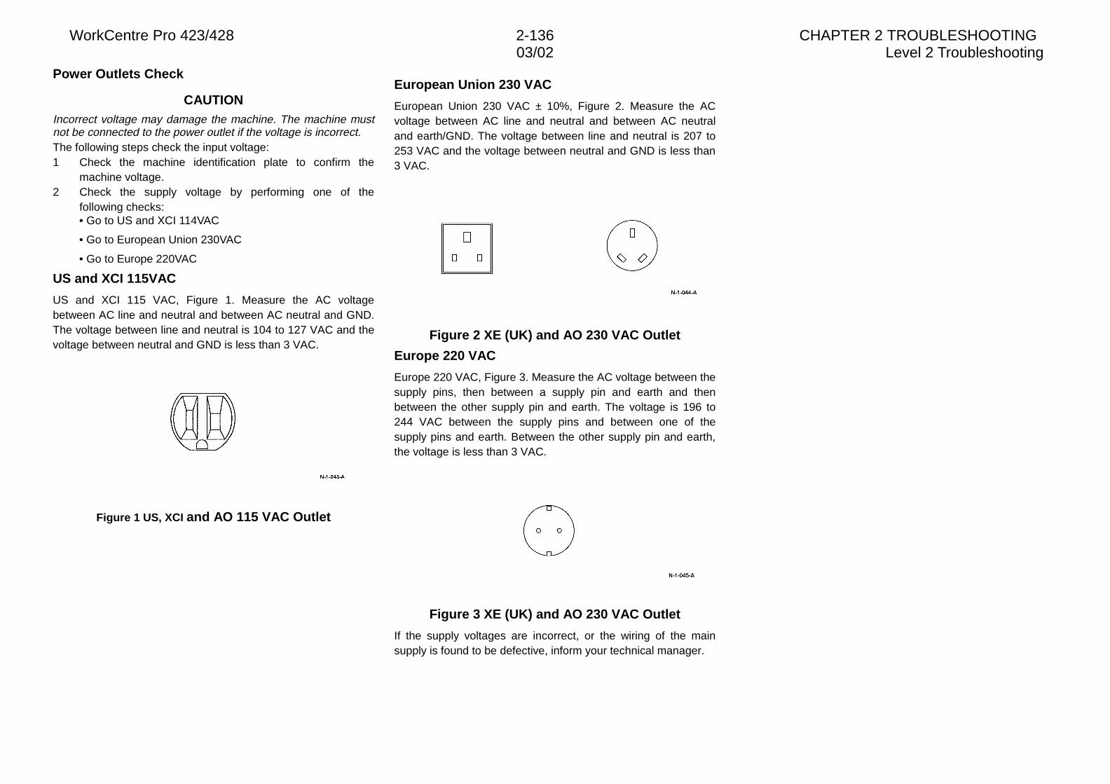
WorkCentre Pro 423/428 2-136 CHAPTER 2 TROUBLESHOOTING03/02 Level 2 Troubleshooting
Power Outlets Check
CAUTIONIncorrect voltage may damage the machine. The machine mustnot be connected to the power outlet if the voltage is incorrect.The following steps check the input voltage:1 Check the machine identification plate to confirm the
machine voltage.2 Check the supply voltage by performing one of the
following checks:• Go to US and XCI 114VAC
• Go to European Union 230VAC
• Go to Europe 220VAC
US and XCI 115VAC
US and XCI 115 VAC, Figure 1. Measure the AC voltagebetween AC line and neutral and between AC neutral and GND.The voltage between line and neutral is 104 to 127 VAC and thevoltage between neutral and GND is less than 3 VAC.
Figure 1 US, XCI and AO 115 VAC Outlet
European Union 230 VAC
European Union 230 VAC ± 10%, Figure 2. Measure the ACvoltage between AC line and neutral and between AC neutraland earth/GND. The voltage between line and neutral is 207 to253 VAC and the voltage between neutral and GND is less than3 VAC.
Figure 2 XE (UK) and AO 230 VAC Outlet
Europe 220 VAC
Europe 220 VAC, Figure 3. Measure the AC voltage between thesupply pins, then between a supply pin and earth and thenbetween the other supply pin and earth. The voltage is 196 to244 VAC between the supply pins and between one of thesupply pins and earth. Between the other supply pin and earth,the voltage is less than 3 VAC.
Figure 3 XE (UK) and AO 230 VAC Outlet
If the supply voltages are incorrect, or the wiring of the mainsupply is found to be defective, inform your technical manager.
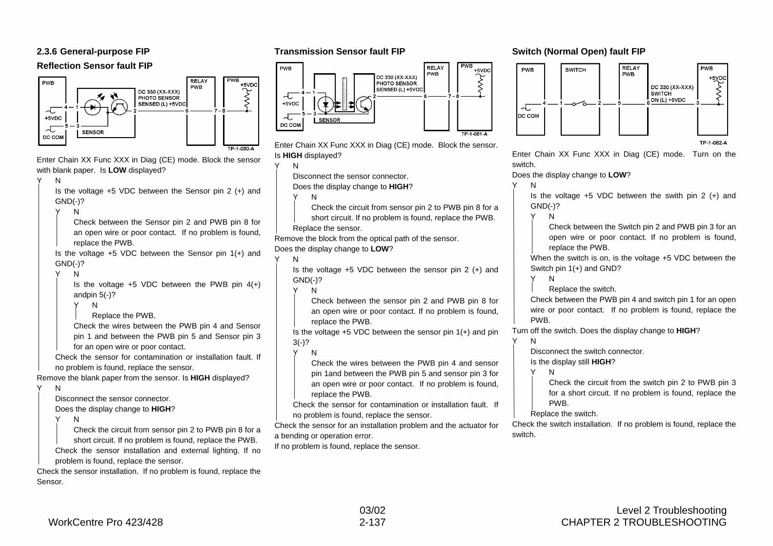
03/02 Level 2 TroubleshootingWorkCentre Pro 423/428 2-137 CHAPTER 2 TROUBLESHOOTING
2.3.6 General-purpose FIP
Reflection Sensor fault FIP
Enter Chain XX Func XXX in Diag (CE) mode. Block the sensorwith blank paper. Is LOW displayed?Y N
Is the voltage +5 VDC between the Sensor pin 2 (+) andGND(-)?Y N
Check between the Sensor pin 2 and PWB pin 8 foran open wire or poor contact. If no problem is found,replace the PWB.
Is the voltage +5 VDC between the Sensor pin 1(+) andGND(-)?Y N
Is the voltage +5 VDC between the PWB pin 4(+)andpin 5(-)?Y N
Replace the PWB.Check the wires between the PWB pin 4 and Sensorpin 1 and between the PWB pin 5 and Sensor pin 3for an open wire or poor contact.
Check the sensor for contamination or installation fault. Ifno problem is found, replace the sensor.
Remove the blank paper from the sensor. Is HIGH displayed?Y N
Disconnect the sensor connector.Does the display change to HIGH?Y N
Check the circuit from sensor pin 2 to PWB pin 8 for ashort circuit. If no problem is found, replace the PWB.
Check the sensor installation and external lighting. If noproblem is found, replace the sensor.
Check the sensor installation. If no problem is found, replace theSensor.
Transmission Sensor fault FIP
Enter Chain XX Func XXX in Diag (CE) mode. Block the sensor.Is HIGH displayed?Y N
Disconnect the sensor connector.Does the display change to HIGH?Y N
Check the circuit from sensor pin 2 to PWB pin 8 for ashort circuit. If no problem is found, replace the PWB.
Replace the sensor.Remove the block from the optical path of the sensor.Does the display change to LOW?Y N
Is the voltage +5 VDC between the sensor pin 2 (+) andGND(-)?Y N
Check between the sensor pin 2 and PWB pin 8 foran open wire or poor contact. If no problem is found,replace the PWB.
Is the voltage +5 VDC between the sensor pin 1(+) and pin3(-)?Y N
Check the wires between the PWB pin 4 and sensorpin 1and between the PWB pin 5 and sensor pin 3 foran open wire or poor contact. If no problem is found,replace the PWB.
Check the sensor for contamination or installation fault. Ifno problem is found, replace the sensor.
Check the sensor for an installation problem and the actuator fora bending or operation error.If no problem is found, replace the sensor.
Switch (Normal Open) fault FIP
Enter Chain XX Func XXX in Diag (CE) mode. Turn on theswitch.Does the display change to LOW?Y N
Is the voltage +5 VDC between the swith pin 2 (+) andGND(-)?Y N
Check between the Switch pin 2 and PWB pin 3 for anopen wire or poor contact. If no problem is found,replace the PWB.
When the switch is on, is the voltage +5 VDC between theSwitch pin 1(+) and GND?Y N
Replace the switch.Check between the PWB pin 4 and switch pin 1 for an openwire or poor contact. If no problem is found, replace thePWB.
Turn off the switch. Does the display change to HIGH?Y N
Disconnect the switch connector.Is the display still HIGH?Y N
Check the circuit from the switch pin 2 to PWB pin 3for a short circuit. If no problem is found, replace thePWB.
Replace the switch.Check the switch installation. If no problem is found, replace theswitch.
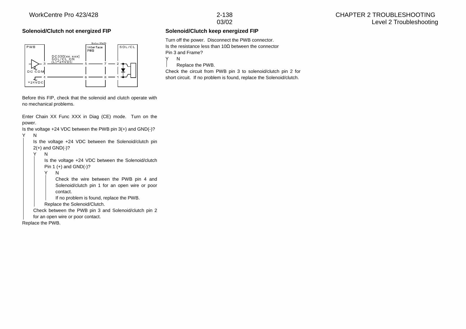
WorkCentre Pro 423/428 2-138 CHAPTER 2 TROUBLESHOOTING03/02 Level 2 Troubleshooting
Solenoid/Clutch not energized FIP
Before this FIP, check that the solenoid and clutch operate withno mechanical problems.
Enter Chain XX Func XXX in Diag (CE) mode. Turn on thepower.Is the voltage +24 VDC between the PWB pin 3(+) and GND(-)?Y N
Is the voltage +24 VDC between the Solenoid/clutch pin2(+) and GND(-)?Y N
Is the voltage +24 VDC between the Solenoid/clutchPin 1 (+) and GND(-)?Y N
Check the wire between the PWB pin 4 andSolenoid/clutch pin 1 for an open wire or poorcontact.If no problem is found, replace the PWB.
Replace the Solenoid/Clutch.Check between the PWB pin 3 and Solenoid/clutch pin 2for an open wire or poor contact.
Replace the PWB.
Solenoid/Clutch keep energized FIP
Turn off the power. Disconnect the PWB connector.Is the resistance less than 10� between the connectorPin 3 and Frame?Y N
Replace the PWB.Check the circuit from PWB pin 3 to solenoid/clutch pin 2 forshort circuit. If no problem is found, replace the Solenoid/clutch.
Relay PWB
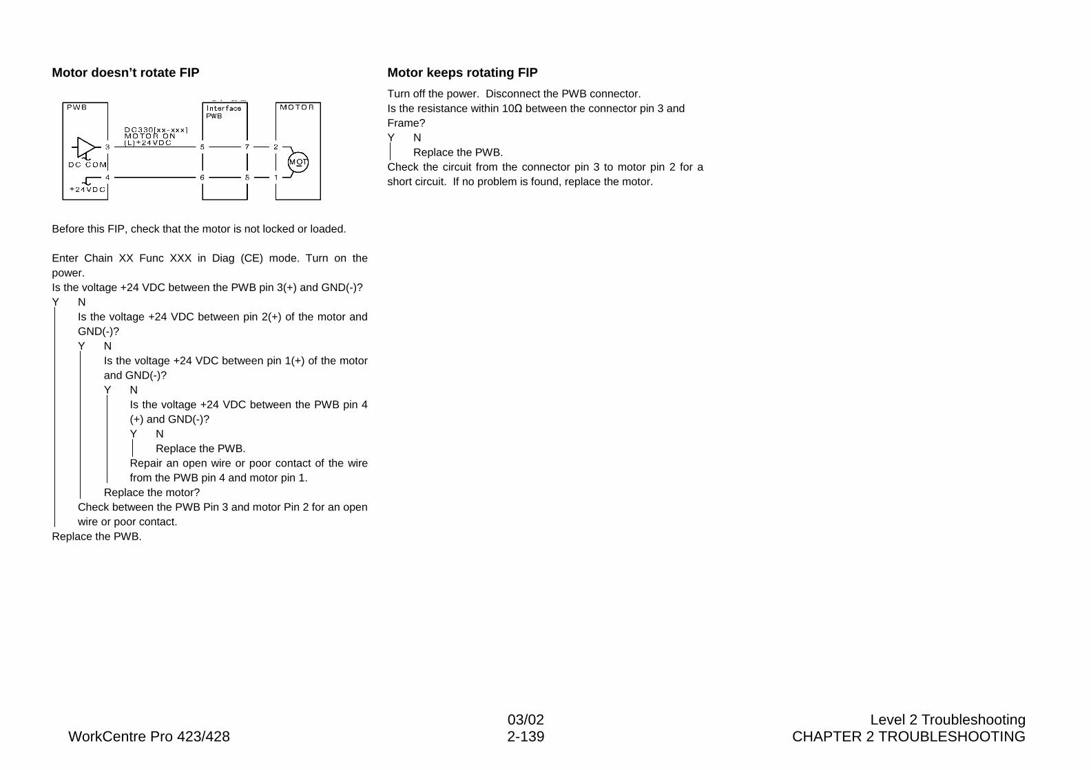
03/02 Level 2 TroubleshootingWorkCentre Pro 423/428 2-139 CHAPTER 2 TROUBLESHOOTING
Motor doesn’t rotate FIP
Before this FIP, check that the motor is not locked or loaded.
Enter Chain XX Func XXX in Diag (CE) mode. Turn on thepower.Is the voltage +24 VDC between the PWB pin 3(+) and GND(-)?Y N
Is the voltage +24 VDC between pin 2(+) of the motor andGND(-)?Y N
Is the voltage +24 VDC between pin 1(+) of the motorand GND(-)?Y N
Is the voltage +24 VDC between the PWB pin 4(+) and GND(-)?Y N
Replace the PWB.Repair an open wire or poor contact of the wirefrom the PWB pin 4 and motor pin 1.
Replace the motor?Check between the PWB Pin 3 and motor Pin 2 for an openwire or poor contact.
Replace the PWB.
Motor keeps rotating FIP
Turn off the power. Disconnect the PWB connector.Is the resistance within 10� between the connector pin 3 andFrame?Y N
Replace the PWB.Check the circuit from the connector pin 3 to motor pin 2 for ashort circuit. If no problem is found, replace the motor.
Relay PWB
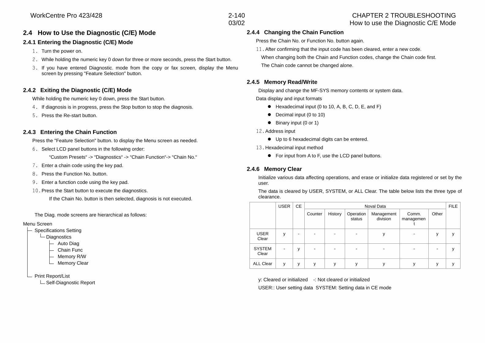
WorkCentre Pro 423/428 2-140 CHAPTER 2 TROUBLESHOOTING03/02 How to use the Diagnostic C/E Mode
2.4 How to Use the Diagnostic (C/E) Mode2.4.1 Entering the Diagnostic (C/E) Mode
�� Turn the power on.
�� While holding the numeric key 0 down for three or more seconds, press the Start button.
�� If you have entered Diagnostic. mode from the copy or fax screen, display the Menuscreen by pressing "Feature Selection" button.
2.4.2 Exiting the Diagnostic (C/E) ModeWhile holding the numeric key 0 down, press the Start button.
�� If diagnosis is in progress, press the Stop button to stop the diagnosis.
�� Press the Re-start button.
2.4.3 Entering the Chain FunctionPress the "Feature Selection" button. to display the Menu screen as needed.
�� Select LCD panel buttons in the following order:
“Custom Presets“ -> “Diagnostics“ -> “Chain Function“-> “Chain No.“
�� Enter a chain code using the key pad.
�� Press the Function No. button.
�� Enter a function code using the key pad.
��� Press the Start button to execute the diagnostics.
If the Chain No. button is then selected, diagnosis is not executed.
The Diag. mode screens are hierarchical as follows:
Menu ScreenSpecifications Setting
DiagnosticsAuto DiagChain FuncMemory R/WMemory Clear
Print Report/ListSelf-Diagnostic Report
2.4.4 Changing the Chain FunctionPress the Chain No. or Function No. button again.
��� After confirming that the input code has been cleared, enter a new code.
When changing both the Chain and Function codes, change the Chain code first.
The Chain code cannot be changed alone.
2.4.5 Memory Read/WriteDisplay and change the MF-SYS memory contents or system data.
Data display and input formats
l Hexadecimal input (0 to 10, A, B, C, D, E, and F)
l Decimal input (0 to 10)
l Binary input (0 or 1)
��� Address input
l Up to 6 hexadecimal digits can be entered.
��� Hexadecimal input method
l For input from A to F, use the LCD panel buttons.
2.4.6 Memory ClearInitialize various data affecting operations, and erase or initialize data registered or set by theuser.
The data is cleared by USER, SYSTEM, or ALL Clear. The table below lists the three type ofclearance.
Noval DataUSER CE
Counter History Operationstatus
Managementdivision
Comm.managemen
t
Other
FILE
USERClear
y - - - - y - y y
SYSTEMClear
- y - - - - - - y
ALL Clear y y y y y y y y y
y: Cleared or initialized -: Not cleared or initialized
USER:: User setting data SYSTEM: Setting data in CE mode
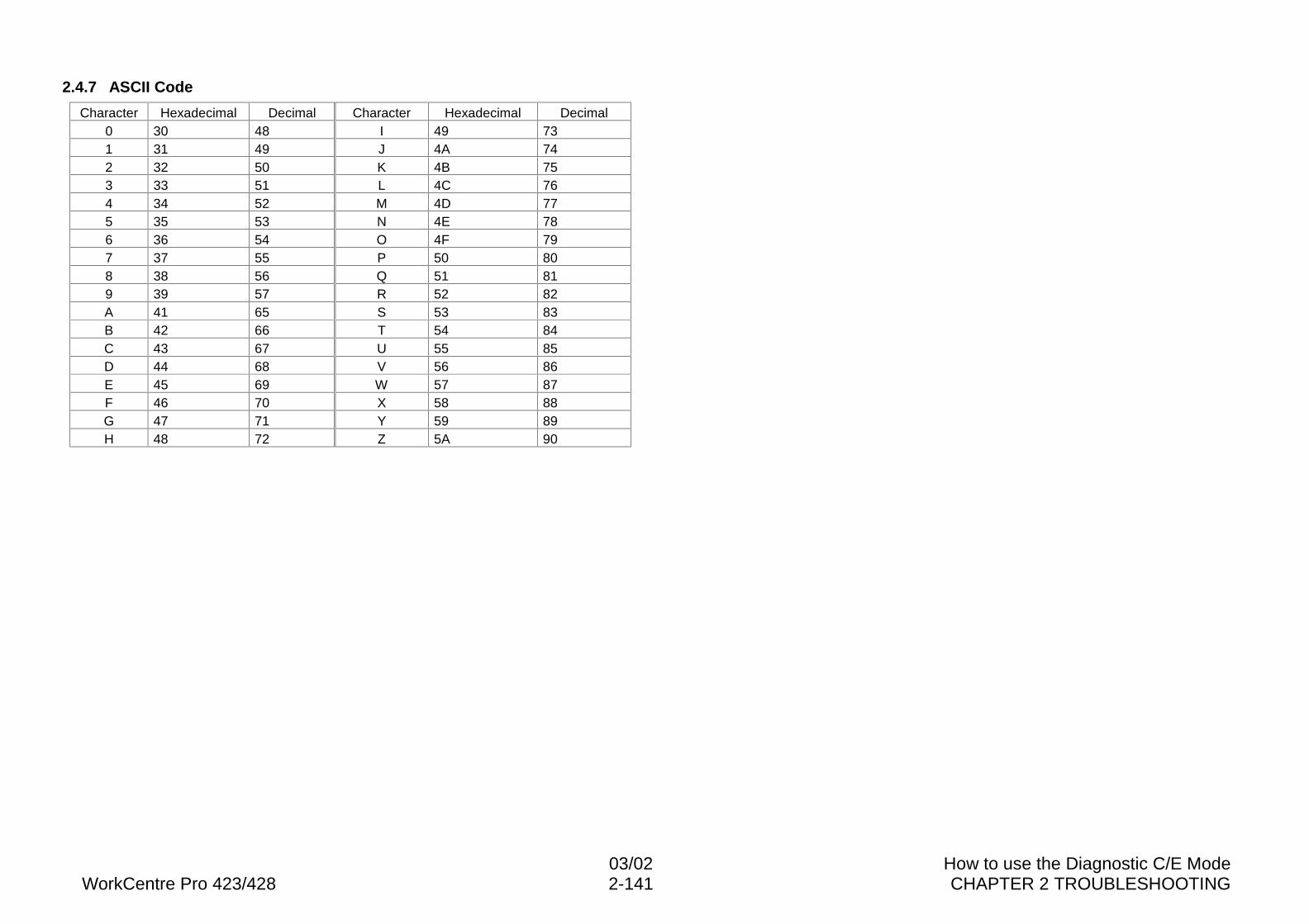
03/02 How to use the Diagnostic C/E ModeWorkCentre Pro 423/428 2-141 CHAPTER 2 TROUBLESHOOTING
2.4.7 ASCII Code
Character Hexadecimal Decimal Character Hexadecimal Decimal0 30 48 I 49 731 31 49 J 4A 742 32 50 K 4B 753 33 51 L 4C 764 34 52 M 4D 775 35 53 N 4E 786 36 54 O 4F 797 37 55 P 50 808 38 56 Q 51 819 39 57 R 52 82A 41 65 S 53 83B 42 66 T 54 84C 43 67 U 55 85D 44 68 V 56 86E 45 69 W 57 87F 46 70 X 58 88G 47 71 Y 59 89H 48 72 Z 5A 90
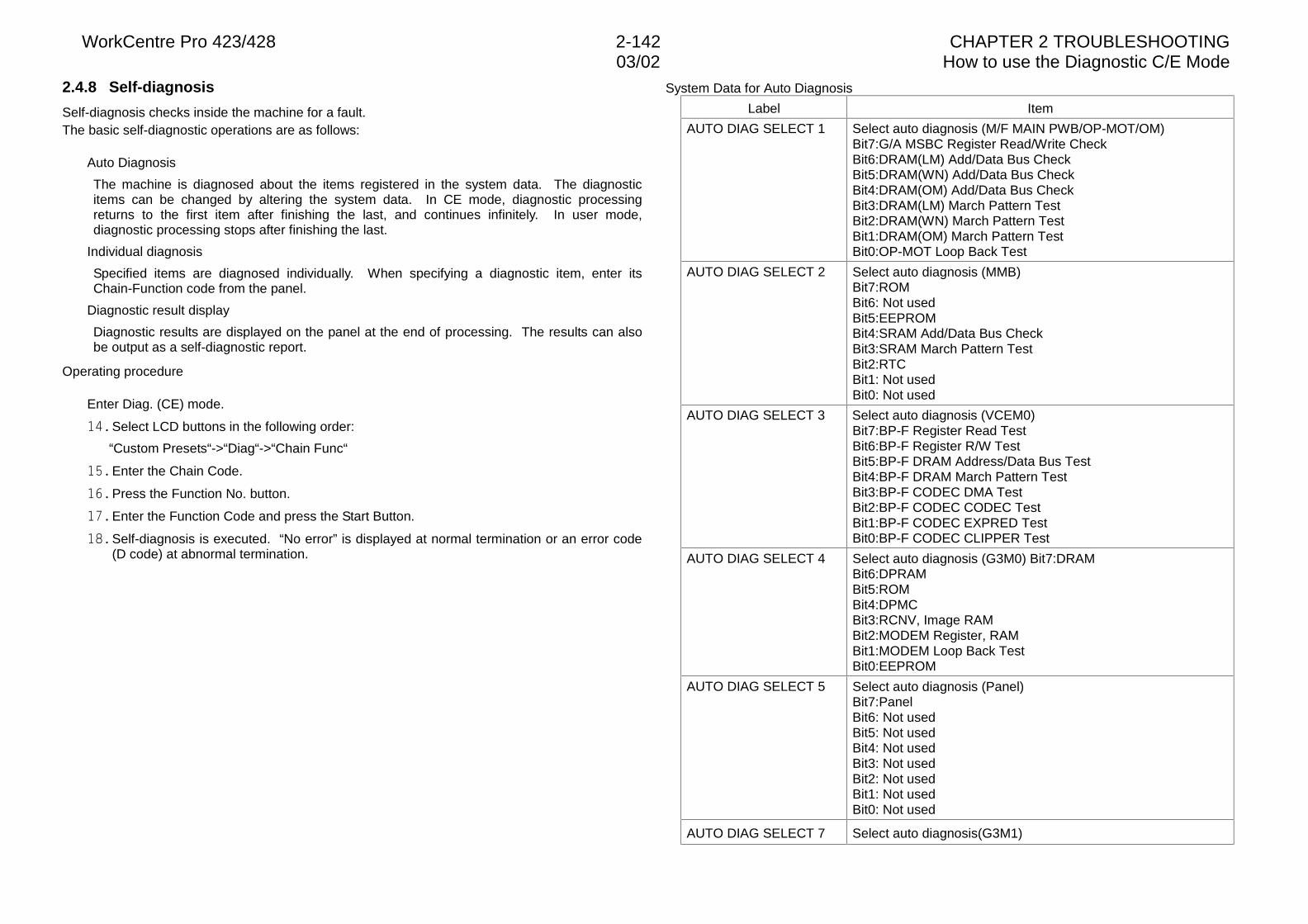
WorkCentre Pro 423/428 2-142 CHAPTER 2 TROUBLESHOOTING03/02 How to use the Diagnostic C/E Mode
2.4.8 Self-diagnosis
Self-diagnosis checks inside the machine for a fault.The basic self-diagnostic operations are as follows:
Auto Diagnosis
The machine is diagnosed about the items registered in the system data. The diagnosticitems can be changed by altering the system data. In CE mode, diagnostic processingreturns to the first item after finishing the last, and continues infinitely. In user mode,diagnostic processing stops after finishing the last.
Individual diagnosis
Specified items are diagnosed individually. When specifying a diagnostic item, enter itsChain-Function code from the panel.
Diagnostic result display
Diagnostic results are displayed on the panel at the end of processing. The results can alsobe output as a self-diagnostic report.
Operating procedure
Enter Diag. (CE) mode.
��� Select LCD buttons in the following order:
“Custom Presets“->“Diag“->“Chain Func“
��� Enter the Chain Code.
��� Press the Function No. button.
��� Enter the Function Code and press the Start Button.
��� Self-diagnosis is executed. “No error” is displayed at normal termination or an error code(D code) at abnormal termination.
System Data for Auto Diagnosis
Label Item
AUTO DIAG SELECT 1 Select auto diagnosis (M/F MAIN PWB/OP-MOT/OM)Bit7:G/A MSBC Register Read/Write CheckBit6:DRAM(LM) Add/Data Bus CheckBit5:DRAM(WN) Add/Data Bus CheckBit4:DRAM(OM) Add/Data Bus CheckBit3:DRAM(LM) March Pattern TestBit2:DRAM(WN) March Pattern TestBit1:DRAM(OM) March Pattern TestBit0:OP-MOT Loop Back Test
AUTO DIAG SELECT 2 Select auto diagnosis (MMB)Bit7:ROMBit6: Not usedBit5:EEPROMBit4:SRAM Add/Data Bus CheckBit3:SRAM March Pattern TestBit2:RTCBit1: Not usedBit0: Not used
AUTO DIAG SELECT 3 Select auto diagnosis (VCEM0)Bit7:BP-F Register Read TestBit6:BP-F Register R/W TestBit5:BP-F DRAM Address/Data Bus TestBit4:BP-F DRAM March Pattern TestBit3:BP-F CODEC DMA TestBit2:BP-F CODEC CODEC TestBit1:BP-F CODEC EXPRED TestBit0:BP-F CODEC CLIPPER Test
AUTO DIAG SELECT 4 Select auto diagnosis (G3M0) Bit7:DRAMBit6:DPRAMBit5:ROMBit4:DPMCBit3:RCNV, Image RAMBit2:MODEM Register, RAMBit1:MODEM Loop Back TestBit0:EEPROM
AUTO DIAG SELECT 5 Select auto diagnosis (Panel)Bit7:PanelBit6: Not usedBit5: Not usedBit4: Not usedBit3: Not usedBit2: Not usedBit1: Not usedBit0: Not used
AUTO DIAG SELECT 7 Select auto diagnosis(G3M1)
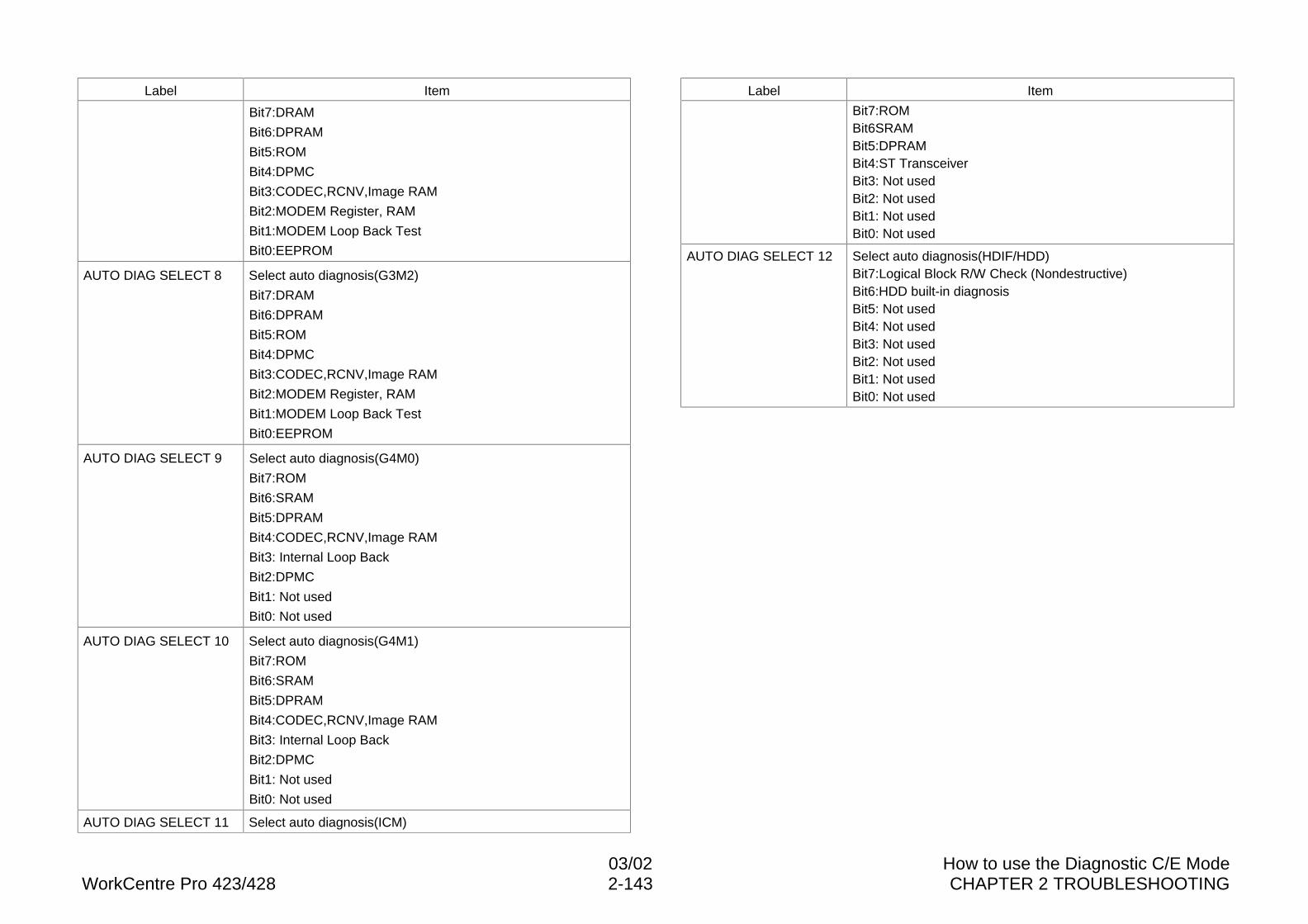
03/02 How to use the Diagnostic C/E ModeWorkCentre Pro 423/428 2-143 CHAPTER 2 TROUBLESHOOTING
Label Item
Bit7:DRAM
Bit6:DPRAM
Bit5:ROM
Bit4:DPMC
Bit3:CODEC,RCNV,Image RAM
Bit2:MODEM Register, RAM
Bit1:MODEM Loop Back Test
Bit0:EEPROM
AUTO DIAG SELECT 8 Select auto diagnosis(G3M2)
Bit7:DRAM
Bit6:DPRAM
Bit5:ROM
Bit4:DPMC
Bit3:CODEC,RCNV,Image RAM
Bit2:MODEM Register, RAM
Bit1:MODEM Loop Back Test
Bit0:EEPROM
AUTO DIAG SELECT 9 Select auto diagnosis(G4M0)
Bit7:ROM
Bit6:SRAM
Bit5:DPRAM
Bit4:CODEC,RCNV,Image RAM
Bit3: Internal Loop Back
Bit2:DPMC
Bit1: Not used
Bit0: Not used
AUTO DIAG SELECT 10 Select auto diagnosis(G4M1)
Bit7:ROM
Bit6:SRAM
Bit5:DPRAM
Bit4:CODEC,RCNV,Image RAM
Bit3: Internal Loop Back
Bit2:DPMC
Bit1: Not used
Bit0: Not used
AUTO DIAG SELECT 11 Select auto diagnosis(ICM)
Label Item
Bit7:ROMBit6SRAMBit5:DPRAMBit4:ST TransceiverBit3: Not usedBit2: Not usedBit1: Not usedBit0: Not used
AUTO DIAG SELECT 12 Select auto diagnosis(HDIF/HDD)Bit7:Logical Block R/W Check (Nondestructive)Bit6:HDD built-in diagnosisBit5: Not usedBit4: Not usedBit3: Not usedBit2: Not usedBit1: Not usedBit0: Not used
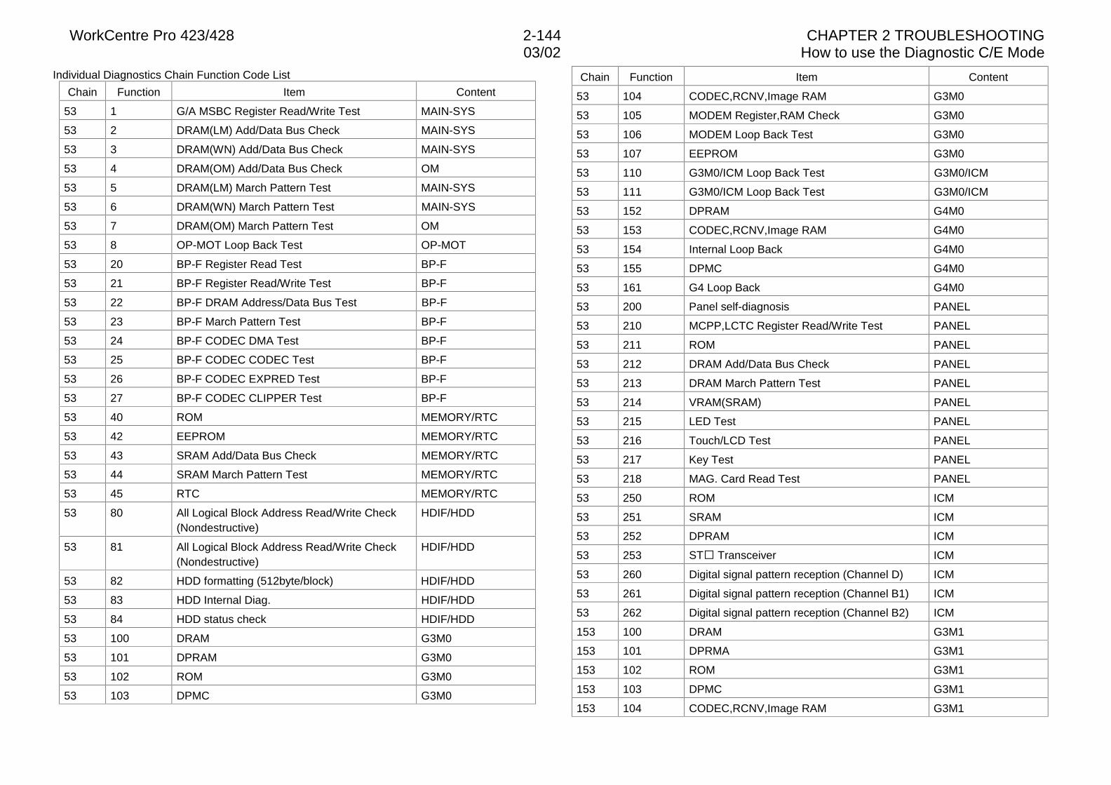
WorkCentre Pro 423/428 2-144 CHAPTER 2 TROUBLESHOOTING03/02 How to use the Diagnostic C/E Mode
Individual Diagnostics Chain Function Code List
Chain Function Item Content
53 1 G/A MSBC Register Read/Write Test MAIN-SYS
53 2 DRAM(LM) Add/Data Bus Check MAIN-SYS
53 3 DRAM(WN) Add/Data Bus Check MAIN-SYS
53 4 DRAM(OM) Add/Data Bus Check OM
53 5 DRAM(LM) March Pattern Test MAIN-SYS
53 6 DRAM(WN) March Pattern Test MAIN-SYS
53 7 DRAM(OM) March Pattern Test OM
53 8 OP-MOT Loop Back Test OP-MOT
53 20 BP-F Register Read Test BP-F
53 21 BP-F Register Read/Write Test BP-F
53 22 BP-F DRAM Address/Data Bus Test BP-F
53 23 BP-F March Pattern Test BP-F
53 24 BP-F CODEC DMA Test BP-F
53 25 BP-F CODEC CODEC Test BP-F
53 26 BP-F CODEC EXPRED Test BP-F
53 27 BP-F CODEC CLIPPER Test BP-F
53 40 ROM MEMORY/RTC
53 42 EEPROM MEMORY/RTC
53 43 SRAM Add/Data Bus Check MEMORY/RTC
53 44 SRAM March Pattern Test MEMORY/RTC
53 45 RTC MEMORY/RTC
53 80 All Logical Block Address Read/Write Check(Nondestructive)
HDIF/HDD
53 81 All Logical Block Address Read/Write Check(Nondestructive)
HDIF/HDD
53 82 HDD formatting (512byte/block) HDIF/HDD
53 83 HDD Internal Diag. HDIF/HDD
53 84 HDD status check HDIF/HDD
53 100 DRAM G3M0
53 101 DPRAM G3M0
53 102 ROM G3M0
53 103 DPMC G3M0
Chain Function Item Content
53 104 CODEC,RCNV,Image RAM G3M0
53 105 MODEM Register,RAM Check G3M0
53 106 MODEM Loop Back Test G3M0
53 107 EEPROM G3M0
53 110 G3M0/ICM Loop Back Test G3M0/ICM
53 111 G3M0/ICM Loop Back Test G3M0/ICM
53 152 DPRAM G4M0
53 153 CODEC,RCNV,Image RAM G4M0
53 154 Internal Loop Back G4M0
53 155 DPMC G4M0
53 161 G4 Loop Back G4M0
53 200 Panel self-diagnosis PANEL
53 210 MCPP,LCTC Register Read/Write Test PANEL
53 211 ROM PANEL
53 212 DRAM Add/Data Bus Check PANEL
53 213 DRAM March Pattern Test PANEL
53 214 VRAM(SRAM) PANEL
53 215 LED Test PANEL
53 216 Touch/LCD Test PANEL
53 217 Key Test PANEL
53 218 MAG. Card Read Test PANEL
53 250 ROM ICM
53 251 SRAM ICM
53 252 DPRAM ICM
53 253 ST� Transceiver ICM
53 260 Digital signal pattern reception (Channel D) ICM
53 261 Digital signal pattern reception (Channel B1) ICM
53 262 Digital signal pattern reception (Channel B2) ICM
153 100 DRAM G3M1
153 101 DPRMA G3M1
153 102 ROM G3M1
153 103 DPMC G3M1
153 104 CODEC,RCNV,Image RAM G3M1
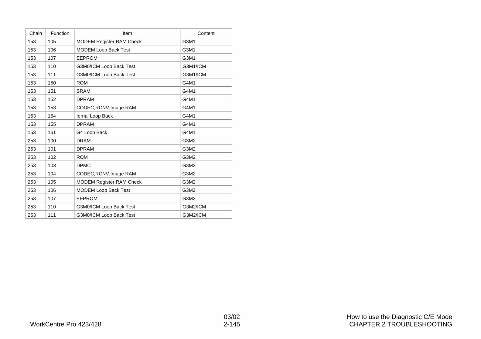
03/02 How to use the Diagnostic C/E ModeWorkCentre Pro 423/428 2-145 CHAPTER 2 TROUBLESHOOTING
Chain Function Item Content
153 105 MODEM Register,RAM Check G3M1
153 106 MODEM Loop Back Test G3M1
153 107 EEPROM G3M1
153 110 G3M0/ICM Loop Back Test G3M1/ICM
153 111 G3M0/ICM Loop Back Test G3M1/ICM
153 150 ROM G4M1
153 151 SRAM G4M1
153 152 DPRAM G4M1
153 153 CODEC,RCNV,Image RAM G4M1
153 154 Iernal Loop Back G4M1
153 155 DPRAM G4M1
153 161 G4 Loop Back G4M1
253 100 DRAM G3M2
253 101 DPRAM G3M2
253 102 ROM G3M2
253 103 DPMC G3M2
253 104 CODEC,RCNV,Image RAM G3M2
253 105 MODEM Register,RAM Check G3M2
253 106 MODEM Loop Back Test G3M2
253 107 EEPROM G3M2
253 110 G3M0/ICM Loop Back Test G3M2/ICM
253 111 G3M0/ICM Loop Back Test G3M2/ICM
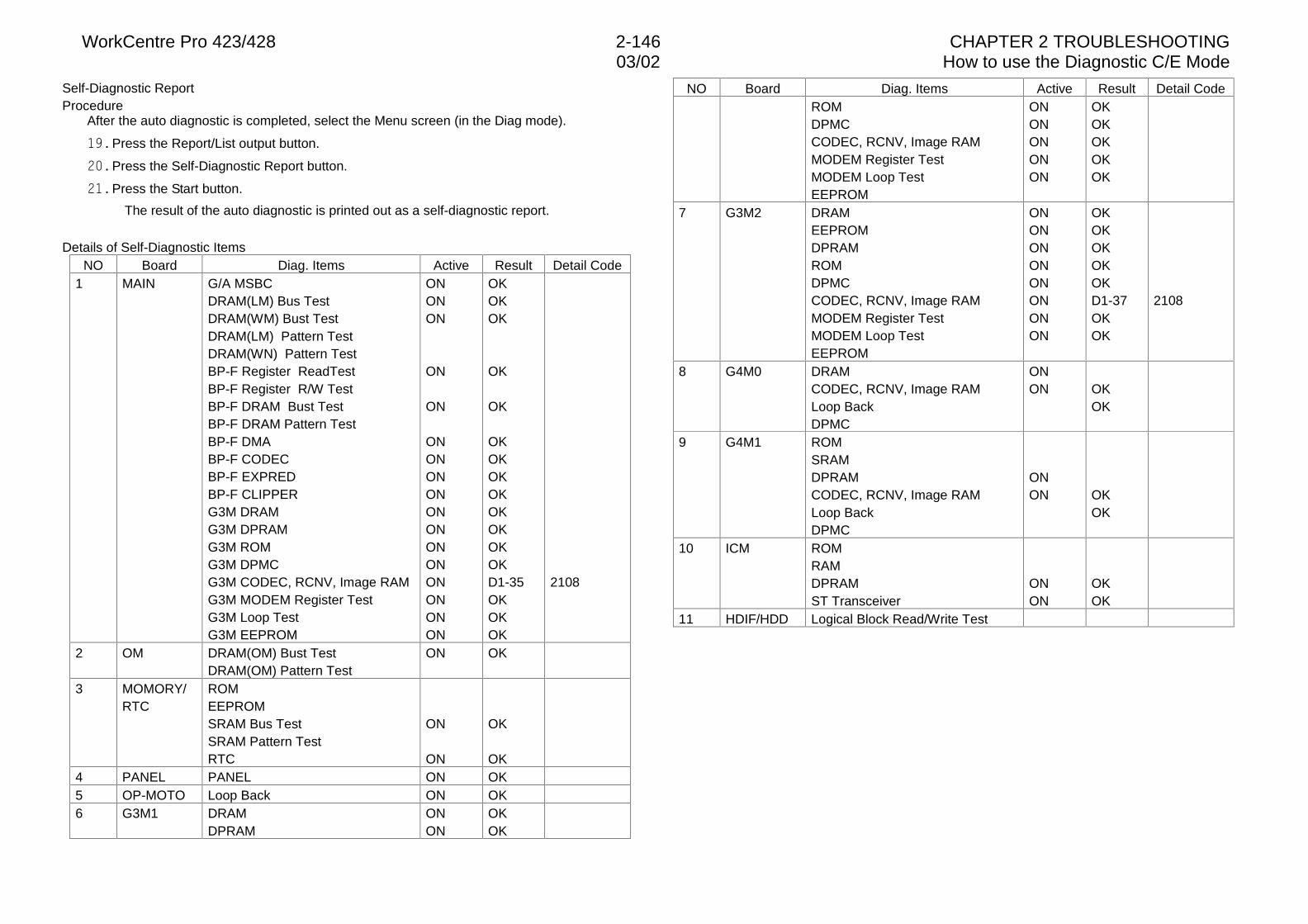
WorkCentre Pro 423/428 2-146 CHAPTER 2 TROUBLESHOOTING03/02 How to use the Diagnostic C/E Mode
Self-Diagnostic ReportProcedure
After the auto diagnostic is completed, select the Menu screen (in the Diag mode).
��� Press the Report/List output button.
��� Press the Self-Diagnostic Report button.
��� Press the Start button.
The result of the auto diagnostic is printed out as a self-diagnostic report.
Details of Self-Diagnostic ItemsNO Board Diag. Items Active Result Detail Code
1 MAIN G/A MSBCDRAM(LM) Bus TestDRAM(WM) Bust TestDRAM(LM) Pattern TestDRAM(WN) Pattern TestBP-F Register ReadTestBP-F Register R/W TestBP-F DRAM Bust TestBP-F DRAM Pattern TestBP-F DMABP-F CODECBP-F EXPREDBP-F CLIPPERG3M DRAMG3M DPRAMG3M ROMG3M DPMCG3M CODEC, RCNV, Image RAMG3M MODEM Register TestG3M Loop TestG3M EEPROM
ONONON
ON
ON
ONONONONONONONONONONONON
OKOKOK
OK
OK
OKOKOKOKOKOKOKOKD1-35OKOKOK
2108
2 OM DRAM(OM) Bust TestDRAM(OM) Pattern Test
ON OK
3 MOMORY/RTC
ROMEEPROMSRAM Bus TestSRAM Pattern TestRTC
ON
ON
OK
OK4 PANEL PANEL ON OK5 OP-MOTO Loop Back ON OK6 G3M1 DRAM
DPRAMONON
OKOK
NO Board Diag. Items Active Result Detail CodeROMDPMCCODEC, RCNV, Image RAMMODEM Register TestMODEM Loop TestEEPROM
ONONONONON
OKOKOKOKOK
7 G3M2 DRAMEEPROMDPRAMROMDPMCCODEC, RCNV, Image RAMMODEM Register TestMODEM Loop TestEEPROM
ONONONONONONONON
OKOKOKOKOKD1-37OKOK
2108
8 G4M0 DRAMCODEC, RCNV, Image RAMLoop BackDPMC
ONON OK
OK
9 G4M1 ROMSRAMDPRAMCODEC, RCNV, Image RAMLoop BackDPMC
ONON OK
OK
10 ICM ROMRAMDPRAMST Transceiver
ONON
OKOK
11 HDIF/HDD Logical Block Read/Write Test
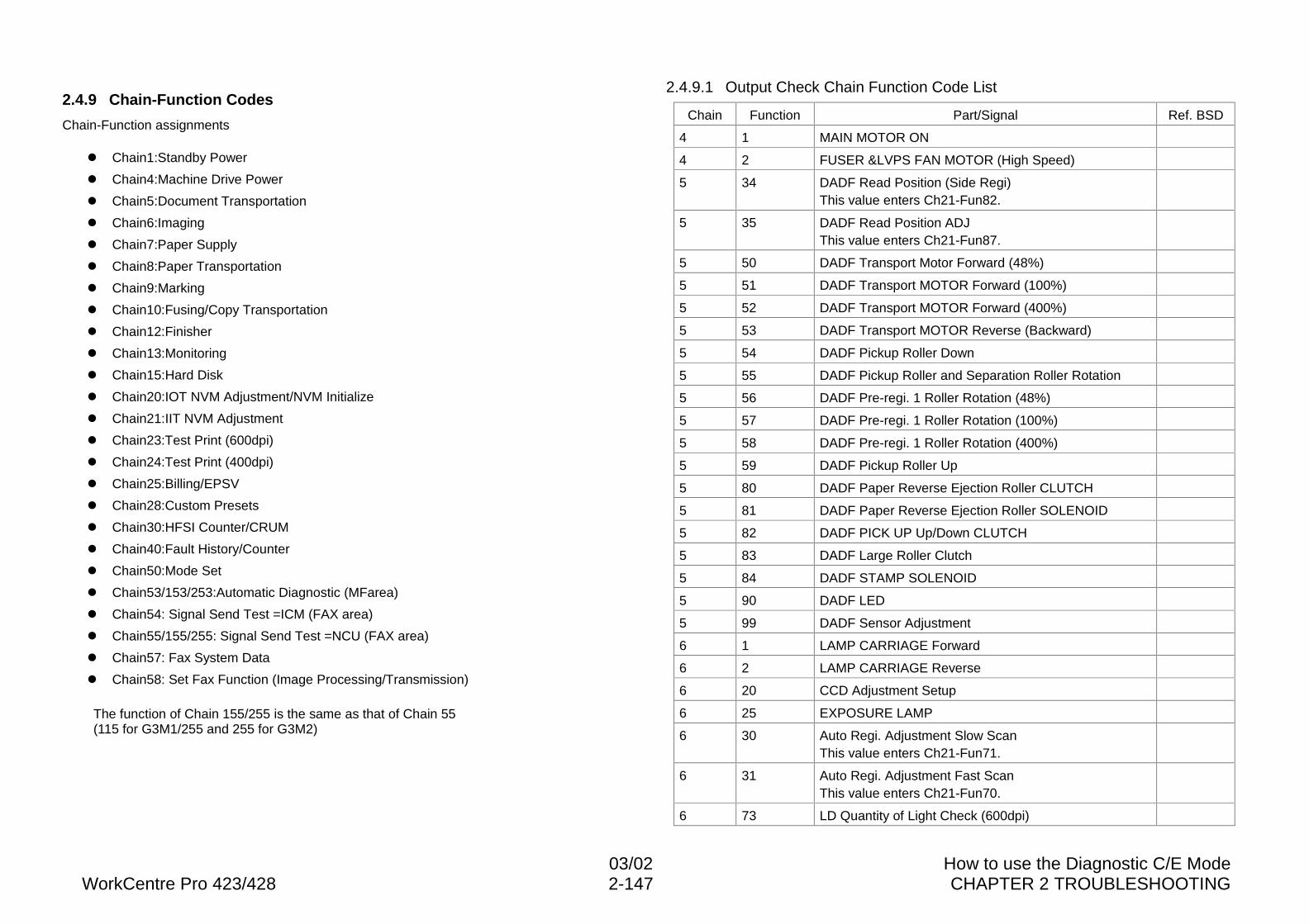
03/02 How to use the Diagnostic C/E ModeWorkCentre Pro 423/428 2-147 CHAPTER 2 TROUBLESHOOTING
2.4.9 Chain-Function Codes
Chain-Function assignments
l Chain1:Standby Power
l Chain4:Machine Drive Power
l Chain5:Document Transportation
l Chain6:Imaging
l Chain7:Paper Supply
l Chain8:Paper Transportation
l Chain9:Marking
l Chain10:Fusing/Copy Transportation
l Chain12:Finisher
l Chain13:Monitoring
l Chain15:Hard Disk
l Chain20:IOT NVM Adjustment/NVM Initialize
l Chain21:IIT NVM Adjustment
l Chain23:Test Print (600dpi)
l Chain24:Test Print (400dpi)
l Chain25:Billing/EPSV
l Chain28:Custom Presets
l Chain30:HFSI Counter/CRUM
l Chain40:Fault History/Counter
l Chain50:Mode Set
l Chain53/153/253:Automatic Diagnostic (MFarea)
l Chain54: Signal Send Test =ICM (FAX area)
l Chain55/155/255: Signal Send Test =NCU (FAX area)
l Chain57: Fax System Data
l Chain58: Set Fax Function (Image Processing/Transmission)
The function of Chain 155/255 is the same as that of Chain 55(115 for G3M1/255 and 255 for G3M2)
2.4.9.1 Output Check Chain Function Code List
Chain Function Part/Signal Ref. BSD
4 1 MAIN MOTOR ON
4 2 FUSER &LVPS FAN MOTOR (High Speed)
5 34 DADF Read Position (Side Regi)This value enters Ch21-Fun82.
5 35 DADF Read Position ADJThis value enters Ch21-Fun87.
5 50 DADF Transport Motor Forward (48%)
5 51 DADF Transport MOTOR Forward (100%)
5 52 DADF Transport MOTOR Forward (400%)
5 53 DADF Transport MOTOR Reverse (Backward)
5 54 DADF Pickup Roller Down
5 55 DADF Pickup Roller and Separation Roller Rotation
5 56 DADF Pre-regi. 1 Roller Rotation (48%)
5 57 DADF Pre-regi. 1 Roller Rotation (100%)
5 58 DADF Pre-regi. 1 Roller Rotation (400%)
5 59 DADF Pickup Roller Up
5 80 DADF Paper Reverse Ejection Roller CLUTCH
5 81 DADF Paper Reverse Ejection Roller SOLENOID
5 82 DADF PICK UP Up/Down CLUTCH
5 83 DADF Large Roller Clutch
5 84 DADF STAMP SOLENOID
5 90 DADF LED
5 99 DADF Sensor Adjustment
6 1 LAMP CARRIAGE Forward
6 2 LAMP CARRIAGE Reverse
6 20 CCD Adjustment Setup
6 25 EXPOSURE LAMP
6 30 Auto Regi. Adjustment Slow ScanThis value enters Ch21-Fun71.
6 31 Auto Regi. Adjustment Fast ScanThis value enters Ch21-Fun70.
6 73 LD Quantity of Light Check (600dpi)
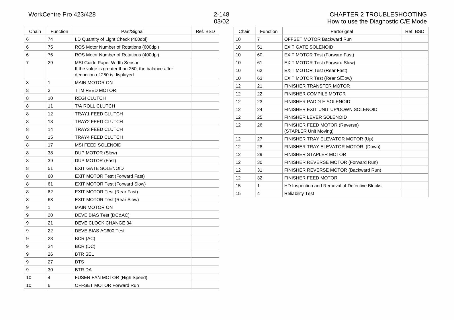
WorkCentre Pro 423/428 2-148 CHAPTER 2 TROUBLESHOOTING03/02 How to use the Diagnostic C/E Mode
Chain Function Part/Signal Ref. BSD
6 74 LD Quantity of Light Check (400dpi)
6 75 ROS Motor Number of Rotations (600dpi)
6 76 ROS Motor Number of Rotations (400dpi)
7 29 MSI Guide Paper Width SensorIf the value is greater than 250, the balance afterdeduction of 250 is displayed.
8 1 MAIN MOTOR ON
8 2 TTM FEED MOTOR
8 10 REGI CLUTCH
8 11 T/A ROLL CLUTCH
8 12 TRAY1 FEED CLUTCH
8 13 TRAY2 FEED CLUTCH
8 14 TRAY3 FEED CLUTCH
8 15 TRAY4 FEED CLUTCH
8 17 MSI FEED SOLENOID
8 38 DUP MOTOR (Slow)
8 39 DUP MOTOR (Fast)
8 51 EXIT GATE SOLENOID
8 60 EXIT MOTOR Test (Forward Fast)
8 61 EXIT MOTOR Test (Forward Slow)
8 62 EXIT MOTOR Test (Rear Fast)
8 63 EXIT MOTOR Test (Rear Slow)
9 1 MAIN MOTOR ON
9 20 DEVE BIAS Test (DC&AC)
9 21 DEVE CLOCK CHANGE 34
9 22 DEVE BIAS AC600 Test
9 23 BCR (AC)
9 24 BCR (DC)
9 26 BTR SEL
9 27 DTS
9 30 BTR DA
10 4 FUSER FAN MOTOR (High Speed)
10 6 OFFSET MOTOR Forward Run
Chain Function Part/Signal Ref. BSD
10 7 OFFSET MOTOR Backward Run
10 51 EXIT GATE SOLENOID
10 60 EXIT MOTOR Test (Forward Fast)
10 61 EXIT MOTOR Test (Forward Slow)
10 62 EXIT MOTOR Test (Rear Fast)
10 63 EXIT MOTOR Test (Rear S�ow)
12 21 FINISHER TRANSFER MOTOR
12 22 FINISHER COMPILE MOTOR
12 23 FINISHER PADDLE SOLENOID
12 24 FINISHER EXIT UNIT UP/DOWN SOLENOID
12 25 FINISHER LEVER SOLENOID
12 26 FINISHER FEED MOTOR (Reverse)(STAPLER Unit Moving)
12 27 FINISHER TRAY ELEVATOR MOTOR (Up)
12 28 FINISHER TRAY ELEVATOR MOTOR (Down)
12 29 FINISHER STAPLER MOTOR
12 30 FINISHER REVERSE MOTOR (Forward Run)
12 31 FINISHER REVERSE MOTOR (Backward Run)
12 32 FINISHER FEED MOTOR
15 1 HD Inspection and Removal of Defective Blocks
15 4 Reliability Test
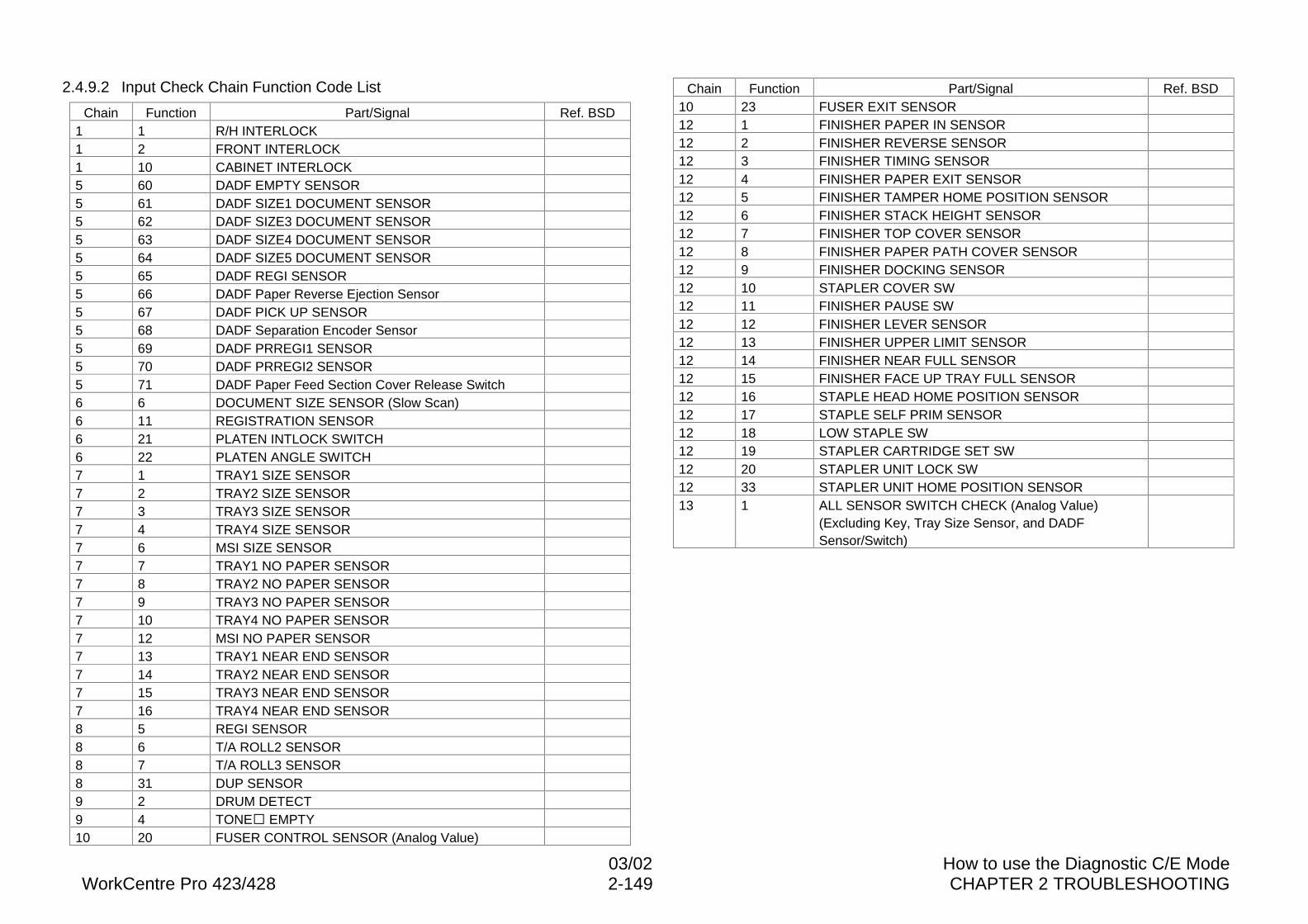
03/02 How to use the Diagnostic C/E ModeWorkCentre Pro 423/428 2-149 CHAPTER 2 TROUBLESHOOTING
2.4.9.2 Input Check Chain Function Code List
Chain Function Part/Signal Ref. BSD1 1 R/H INTERLOCK1 2 FRONT INTERLOCK1 10 CABINET INTERLOCK5 60 DADF EMPTY SENSOR5 61 DADF SIZE1 DOCUMENT SENSOR5 62 DADF SIZE3 DOCUMENT SENSOR5 63 DADF SIZE4 DOCUMENT SENSOR5 64 DADF SIZE5 DOCUMENT SENSOR5 65 DADF REGI SENSOR5 66 DADF Paper Reverse Ejection Sensor5 67 DADF PICK UP SENSOR5 68 DADF Separation Encoder Sensor5 69 DADF PRREGI1 SENSOR5 70 DADF PRREGI2 SENSOR5 71 DADF Paper Feed Section Cover Release Switch6 6 DOCUMENT SIZE SENSOR (Slow Scan)6 11 REGISTRATION SENSOR6 21 PLATEN INTLOCK SWITCH6 22 PLATEN ANGLE SWITCH7 1 TRAY1 SIZE SENSOR7 2 TRAY2 SIZE SENSOR7 3 TRAY3 SIZE SENSOR7 4 TRAY4 SIZE SENSOR7 6 MSI SIZE SENSOR7 7 TRAY1 NO PAPER SENSOR7 8 TRAY2 NO PAPER SENSOR7 9 TRAY3 NO PAPER SENSOR7 10 TRAY4 NO PAPER SENSOR7 12 MSI NO PAPER SENSOR7 13 TRAY1 NEAR END SENSOR7 14 TRAY2 NEAR END SENSOR7 15 TRAY3 NEAR END SENSOR7 16 TRAY4 NEAR END SENSOR8 5 REGI SENSOR8 6 T/A ROLL2 SENSOR8 7 T/A ROLL3 SENSOR8 31 DUP SENSOR9 2 DRUM DETECT9 4 TONE� EMPTY10 20 FUSER CONTROL SENSOR (Analog Value)
Chain Function Part/Signal Ref. BSD10 23 FUSER EXIT SENSOR12 1 FINISHER PAPER IN SENSOR12 2 FINISHER REVERSE SENSOR12 3 FINISHER TIMING SENSOR12 4 FINISHER PAPER EXIT SENSOR12 5 FINISHER TAMPER HOME POSITION SENSOR12 6 FINISHER STACK HEIGHT SENSOR12 7 FINISHER TOP COVER SENSOR12 8 FINISHER PAPER PATH COVER SENSOR12 9 FINISHER DOCKING SENSOR12 10 STAPLER COVER SW12 11 FINISHER PAUSE SW12 12 FINISHER LEVER SENSOR12 13 FINISHER UPPER LIMIT SENSOR12 14 FINISHER NEAR FULL SENSOR12 15 FINISHER FACE UP TRAY FULL SENSOR12 16 STAPLE HEAD HOME POSITION SENSOR12 17 STAPLE SELF PRIM SENSOR12 18 LOW STAPLE SW12 19 STAPLER CARTRIDGE SET SW12 20 STAPLER UNIT LOCK SW12 33 STAPLER UNIT HOME POSITION SENSOR13 1 ALL SENSOR SWITCH CHECK (Analog Value)
(Excluding Key, Tray Size Sensor, and DADFSensor/Switch)
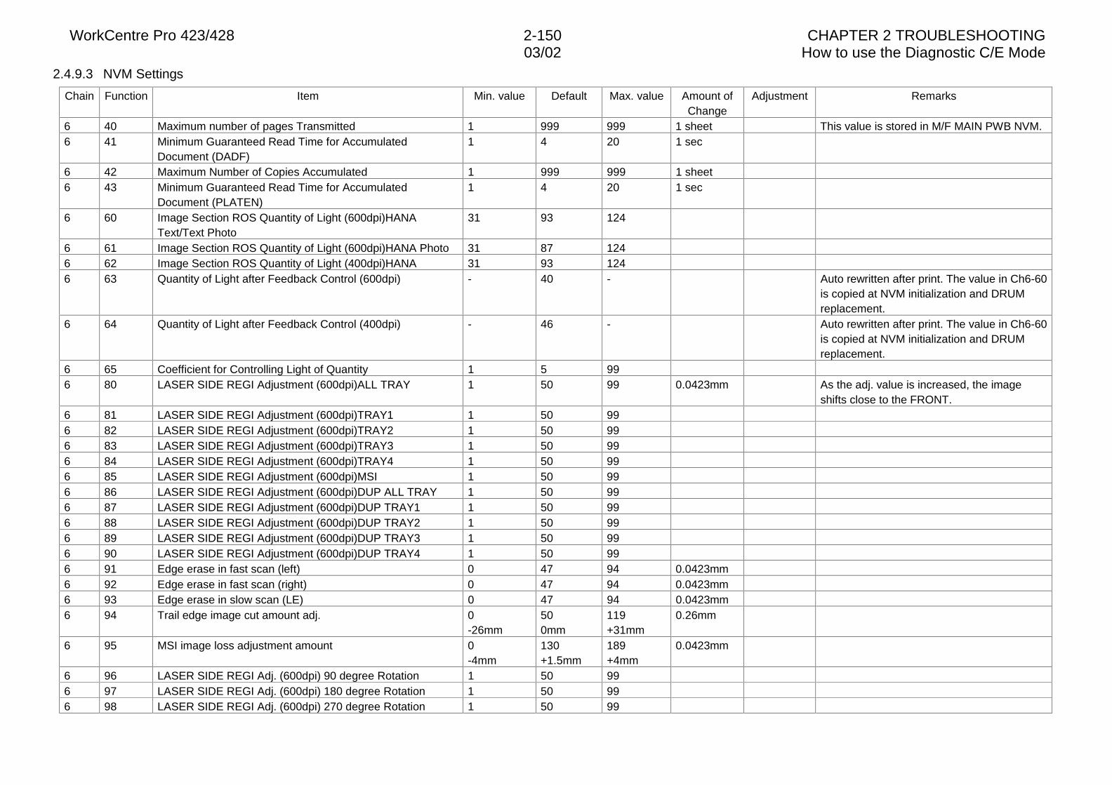
WorkCentre Pro 423/428 2-150 CHAPTER 2 TROUBLESHOOTING03/02 How to use the Diagnostic C/E Mode
2.4.9.3 NVM Settings
Chain Function Item Min. value Default Max. value Amount ofChange
Adjustment Remarks
6 40 Maximum number of pages Transmitted 1 999 999 1 sheet This value is stored in M/F MAIN PWB NVM.6 41 Minimum Guaranteed Read Time for Accumulated
Document (DADF)1 4 20 1 sec
6 42 Maximum Number of Copies Accumulated 1 999 999 1 sheet6 43 Minimum Guaranteed Read Time for Accumulated
Document (PLATEN)1 4 20 1 sec
6 60 Image Section ROS Quantity of Light (600dpi)HANAText/Text Photo
31 93 124
6 61 Image Section ROS Quantity of Light (600dpi)HANA Photo 31 87 1246 62 Image Section ROS Quantity of Light (400dpi)HANA 31 93 1246 63 Quantity of Light after Feedback Control (600dpi) - 40 - Auto rewritten after print. The value in Ch6-60
is copied at NVM initialization and DRUMreplacement.
6 64 Quantity of Light after Feedback Control (400dpi) - 46 - Auto rewritten after print. The value in Ch6-60is copied at NVM initialization and DRUMreplacement.
6 65 Coefficient for Controlling Light of Quantity 1 5 996 80 LASER SIDE REGI Adjustment (600dpi)ALL TRAY 1 50 99 0.0423mm As the adj. value is increased, the image
shifts close to the FRONT.6 81 LASER SIDE REGI Adjustment (600dpi)TRAY1 1 50 996 82 LASER SIDE REGI Adjustment (600dpi)TRAY2 1 50 996 83 LASER SIDE REGI Adjustment (600dpi)TRAY3 1 50 996 84 LASER SIDE REGI Adjustment (600dpi)TRAY4 1 50 996 85 LASER SIDE REGI Adjustment (600dpi)MSI 1 50 996 86 LASER SIDE REGI Adjustment (600dpi)DUP ALL TRAY 1 50 996 87 LASER SIDE REGI Adjustment (600dpi)DUP TRAY1 1 50 996 88 LASER SIDE REGI Adjustment (600dpi)DUP TRAY2 1 50 996 89 LASER SIDE REGI Adjustment (600dpi)DUP TRAY3 1 50 996 90 LASER SIDE REGI Adjustment (600dpi)DUP TRAY4 1 50 996 91 Edge erase in fast scan (left) 0 47 94 0.0423mm6 92 Edge erase in fast scan (right) 0 47 94 0.0423mm6 93 Edge erase in slow scan (LE) 0 47 94 0.0423mm6 94 Trail edge image cut amount adj. 0
-26mm500mm
119+31mm
0.26mm
6 95 MSI image loss adjustment amount 0-4mm
130+1.5mm
189+4mm
0.0423mm
6 96 LASER SIDE REGI Adj. (600dpi) 90 degree Rotation 1 50 996 97 LASER SIDE REGI Adj. (600dpi) 180 degree Rotation 1 50 996 98 LASER SIDE REGI Adj. (600dpi) 270 degree Rotation 1 50 99
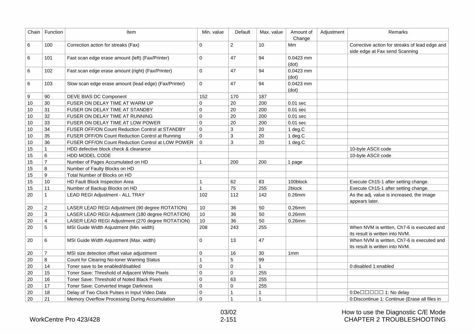
03/02 How to use the Diagnostic C/E ModeWorkCentre Pro 423/428 2-151 CHAPTER 2 TROUBLESHOOTING
Chain Function Item Min. value Default Max. value Amount ofChange
Adjustment Remarks
6 100 Correction action for streaks (Fax) 0 2 10 Mm Corrective action for streaks of lead edge andside edge at Fax send Scanning
6 101 Fast scan edge erase amount (left) (Fax/Printer) 0 47 94 0.0423 mm(dot)
6 102 Fast scan edge erase amount (right) (Fax/Printer) 0 47 94 0.0423 mm(dot)
6 103 Slow scan edge erase amount (lead edge) (Fax/Printer) 0 47 94 0.0423 mm(dot)
9 90 DEVE BIAS DC Component 152 170 18710 30 FUSER ON DELAY TIME AT WARM UP 0 20 200 0.01 sec10 31 FUSER ON DELAY TIME AT STANDBY 0 20 200 0.01 sec10 32 FUSER ON DELAY TIME AT RUNNING 0 20 200 0.01 sec10 33 FUSER ON DELAY TIME AT LOW POWER 0 20 200 0.01 sec10 34 FUSER OFF/ON Count Reduction Control at STANDBY 0 3 20 1 deg.C10 35 FUSER OFF/ON Count Reduction Control at Running 0 3 20 1 deg.C10 36 FUSER OFF/ON Count Reduction Control at LOW POWER 0 3 20 1 deg.C15 1 HDD defective block check & clearance 10-byte ASCII code15 6 HDD MODEL CODE 10-byte ASCII code15 7 Number of Pages Accumulated on HD 1 200 200 1 page15 8 Number of Faulty Blocks on HD15 9 Total Number of Blocks on HD15 10 HD Fault Block Inspection Area 1 62 83 100block Execute Ch15-1 after setting change.15 11 Number of Backup Blocks on HD 1 75 255 2block Execute Ch15-1 after setting change.20 1 LEAD REGI Adjustment - ALL TRAY 102 112 142 0.26mm As the adj. value is increased, the image
appears later.20 2 LASER LEAD REGI Adjustment (90 degree ROTATION) 10 36 50 0.26mm20 3 LASER LEAD REGI Adjustment (180 degree ROTATION) 10 36 50 0.26mm20 4 LASER LEAD REGI Adjustment (270 degree ROTATION) 10 36 50 0.26mm20 5 MSI Guide Width Asjustment (Min. width) 208 243 255 When NVM is written, Ch7-6 is executed and
its result is written into NVM.20 6 MSI Guide Width Asjustment (Max. width) 0 13 47 When NVM is written, Ch7-6 is executed and
its result is written into NVM.20 7 MSI size detection offset value adjustment 0 16 30 1mm20 8 Count for Clearing No-toner Warning Status 1 5 9920 14 Toner save to be enabled/disabled 0 0 1 0:disabled 1:enabled20 15 Toner Save: Threshold of Adjacent White Pixels 0 0 25520 16 Toner Save: Threshold of Noted Black Pixels 0 63 25520 17 Toner Save: Converted Image Darkness 0 0 25520 18 Delay of Two Clock Pulses in Input Video Data 0 1 1 0:De����� 1: No delay20 21 Memory Overflow Processing During Accumulation 0 1 1 0:Discontinue 1: Continue (Erase all files in
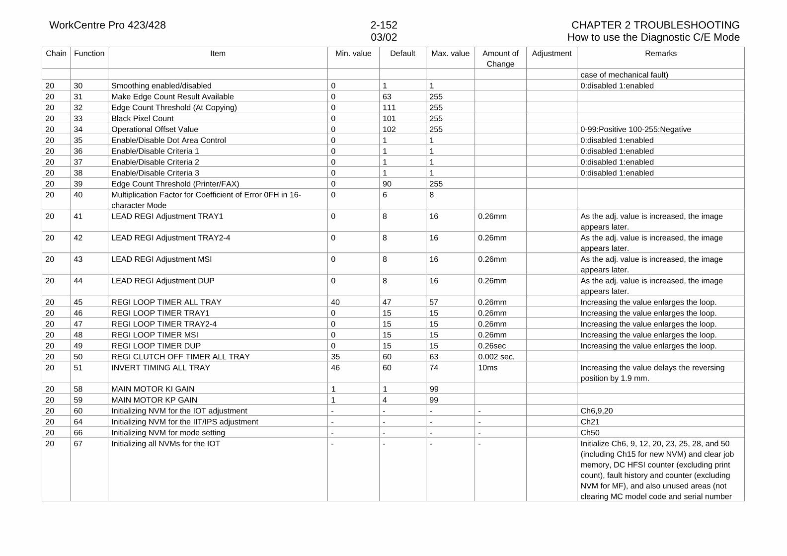
WorkCentre Pro 423/428 2-152 CHAPTER 2 TROUBLESHOOTING03/02 How to use the Diagnostic C/E Mode
Chain Function Item Min. value Default Max. value Amount ofChange
Adjustment Remarks
case of mechanical fault)20 30 Smoothing enabled/disabled 0 1 1 0:disabled 1:enabled20 31 Make Edge Count Result Available 0 63 25520 32 Edge Count Threshold (At Copying) 0 111 25520 33 Black Pixel Count 0 101 25520 34 Operational Offset Value 0 102 255 0-99:Positive 100-255:Negative20 35 Enable/Disable Dot Area Control 0 1 1 0:disabled 1:enabled20 36 Enable/Disable Criteria 1 0 1 1 0:disabled 1:enabled20 37 Enable/Disable Criteria 2 0 1 1 0:disabled 1:enabled20 38 Enable/Disable Criteria 3 0 1 1 0:disabled 1:enabled20 39 Edge Count Threshold (Printer/FAX) 0 90 25520 40 Multiplication Factor for Coefficient of Error 0FH in 16-
character Mode0 6 8
20 41 LEAD REGI Adjustment TRAY1 0 8 16 0.26mm As the adj. value is increased, the imageappears later.
20 42 LEAD REGI Adjustment TRAY2-4 0 8 16 0.26mm As the adj. value is increased, the imageappears later.
20 43 LEAD REGI Adjustment MSI 0 8 16 0.26mm As the adj. value is increased, the imageappears later.
20 44 LEAD REGI Adjustment DUP 0 8 16 0.26mm As the adj. value is increased, the imageappears later.
20 45 REGI LOOP TIMER ALL TRAY 40 47 57 0.26mm Increasing the value enlarges the loop.20 46 REGI LOOP TIMER TRAY1 0 15 15 0.26mm Increasing the value enlarges the loop.20 47 REGI LOOP TIMER TRAY2-4 0 15 15 0.26mm Increasing the value enlarges the loop.20 48 REGI LOOP TIMER MSI 0 15 15 0.26mm Increasing the value enlarges the loop.20 49 REGI LOOP TIMER DUP 0 15 15 0.26sec Increasing the value enlarges the loop.20 50 REGI CLUTCH OFF TIMER ALL TRAY 35 60 63 0.002 sec.20 51 INVERT TIMING ALL TRAY 46 60 74 10ms Increasing the value delays the reversing
position by 1.9 mm.20 58 MAIN MOTOR KI GAIN 1 1 9920 59 MAIN MOTOR KP GAIN 1 4 9920 60 Initializing NVM for the IOT adjustment - - - - Ch6,9,2020 64 Initializing NVM for the IIT/IPS adjustment - - - - Ch2120 66 Initializing NVM for mode setting - - - - Ch5020 67 Initializing all NVMs for the IOT - - - - Initialize Ch6, 9, 12, 20, 23, 25, 28, and 50
(including Ch15 for new NVM) and clear jobmemory, DC HFSI counter (excluding printcount), fault history and counter (excludingNVM for MF), and also unused areas (notclearing MC model code and serial number
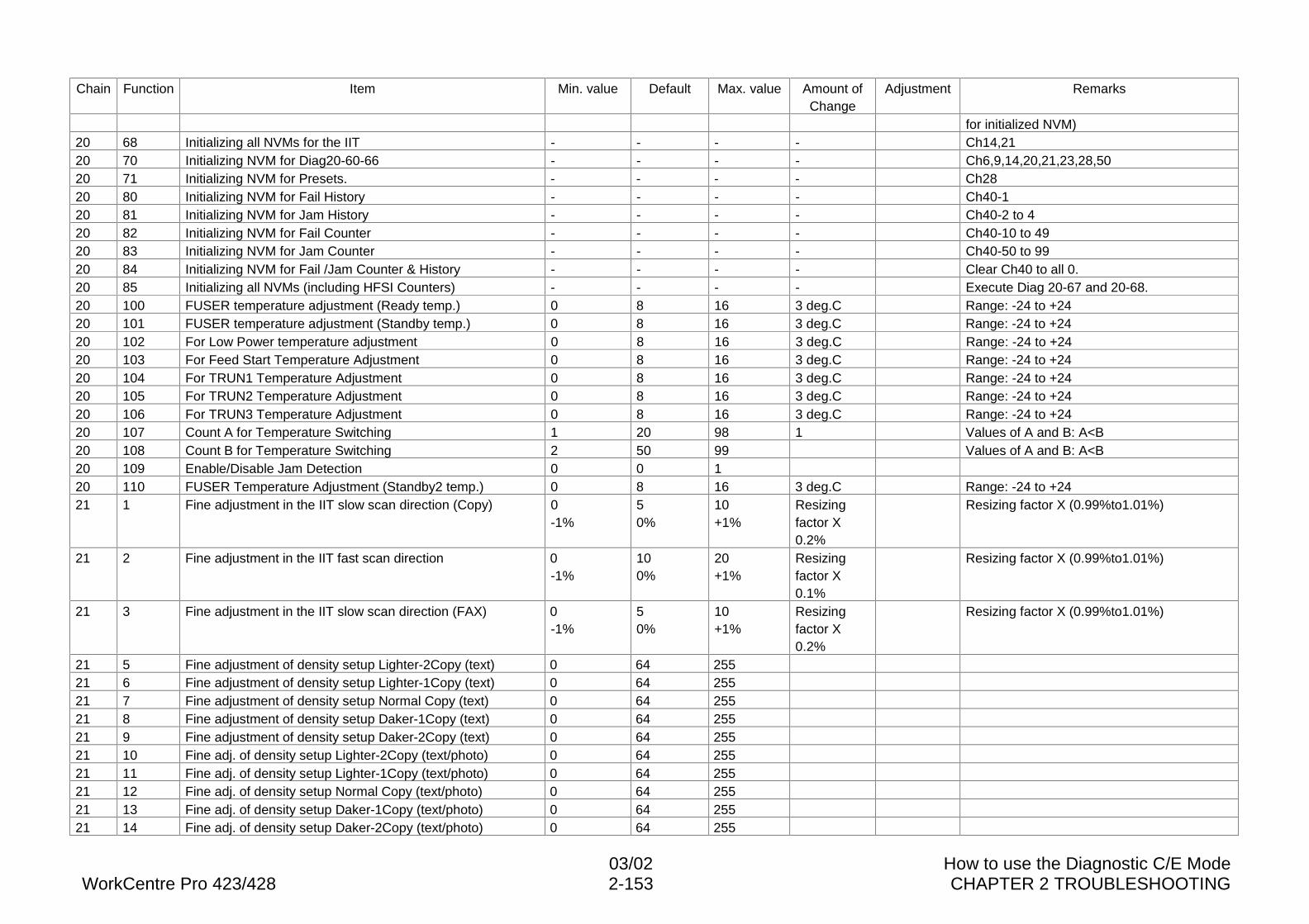
03/02 How to use the Diagnostic C/E ModeWorkCentre Pro 423/428 2-153 CHAPTER 2 TROUBLESHOOTING
Chain Function Item Min. value Default Max. value Amount ofChange
Adjustment Remarks
for initialized NVM)20 68 Initializing all NVMs for the IIT - - - - Ch14,2120 70 Initializing NVM for Diag20-60-66 - - - - Ch6,9,14,20,21,23,28,5020 71 Initializing NVM for Presets. - - - - Ch2820 80 Initializing NVM for Fail History - - - - Ch40-120 81 Initializing NVM for Jam History - - - - Ch40-2 to 420 82 Initializing NVM for Fail Counter - - - - Ch40-10 to 4920 83 Initializing NVM for Jam Counter - - - - Ch40-50 to 9920 84 Initializing NVM for Fail /Jam Counter & History - - - - Clear Ch40 to all 0.20 85 Initializing all NVMs (including HFSI Counters) - - - - Execute Diag 20-67 and 20-68.20 100 FUSER temperature adjustment (Ready temp.) 0 8 16 3 deg.C Range: -24 to +2420 101 FUSER temperature adjustment (Standby temp.) 0 8 16 3 deg.C Range: -24 to +2420 102 For Low Power temperature adjustment 0 8 16 3 deg.C Range: -24 to +2420 103 For Feed Start Temperature Adjustment 0 8 16 3 deg.C Range: -24 to +2420 104 For TRUN1 Temperature Adjustment 0 8 16 3 deg.C Range: -24 to +2420 105 For TRUN2 Temperature Adjustment 0 8 16 3 deg.C Range: -24 to +2420 106 For TRUN3 Temperature Adjustment 0 8 16 3 deg.C Range: -24 to +2420 107 Count A for Temperature Switching 1 20 98 1 Values of A and B: A<B20 108 Count B for Temperature Switching 2 50 99 Values of A and B: A<B20 109 Enable/Disable Jam Detection 0 0 120 110 FUSER Temperature Adjustment (Standby2 temp.) 0 8 16 3 deg.C Range: -24 to +2421 1 Fine adjustment in the IIT slow scan direction (Copy) 0
-1%50%
10+1%
Resizingfactor X0.2%
Resizing factor X (0.99%to1.01%)
21 2 Fine adjustment in the IIT fast scan direction 0-1%
100%
20+1%
Resizingfactor X0.1%
Resizing factor X (0.99%to1.01%)
21 3 Fine adjustment in the IIT slow scan direction (FAX) 0-1%
50%
10+1%
Resizingfactor X0.2%
Resizing factor X (0.99%to1.01%)
21 5 Fine adjustment of density setup Lighter-2Copy (text) 0 64 25521 6 Fine adjustment of density setup Lighter-1Copy (text) 0 64 25521 7 Fine adjustment of density setup Normal Copy (text) 0 64 25521 8 Fine adjustment of density setup Daker-1Copy (text) 0 64 25521 9 Fine adjustment of density setup Daker-2Copy (text) 0 64 25521 10 Fine adj. of density setup Lighter-2Copy (text/photo) 0 64 25521 11 Fine adj. of density setup Lighter-1Copy (text/photo) 0 64 25521 12 Fine adj. of density setup Normal Copy (text/photo) 0 64 25521 13 Fine adj. of density setup Daker-1Copy (text/photo) 0 64 25521 14 Fine adj. of density setup Daker-2Copy (text/photo) 0 64 255
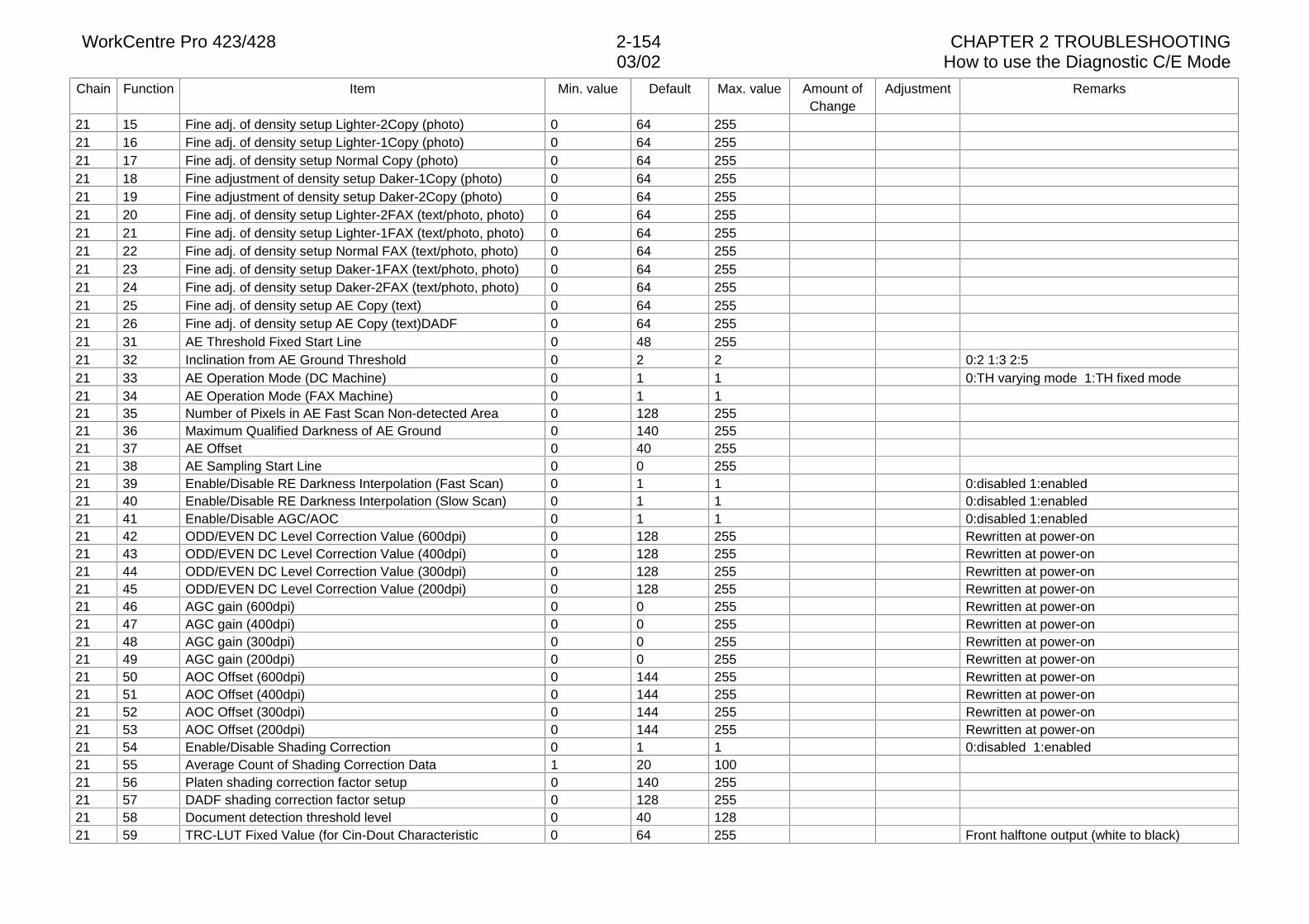
WorkCentre Pro 423/428 2-154 CHAPTER 2 TROUBLESHOOTING03/02 How to use the Diagnostic C/E Mode
Chain Function Item Min. value Default Max. value Amount ofChange
Adjustment Remarks
21 15 Fine adj. of density setup Lighter-2Copy (photo) 0 64 25521 16 Fine adj. of density setup Lighter-1Copy (photo) 0 64 25521 17 Fine adj. of density setup Normal Copy (photo) 0 64 25521 18 Fine adjustment of density setup Daker-1Copy (photo) 0 64 25521 19 Fine adjustment of density setup Daker-2Copy (photo) 0 64 25521 20 Fine adj. of density setup Lighter-2FAX (text/photo, photo) 0 64 25521 21 Fine adj. of density setup Lighter-1FAX (text/photo, photo) 0 64 25521 22 Fine adj. of density setup Normal FAX (text/photo, photo) 0 64 25521 23 Fine adj. of density setup Daker-1FAX (text/photo, photo) 0 64 25521 24 Fine adj. of density setup Daker-2FAX (text/photo, photo) 0 64 25521 25 Fine adj. of density setup AE Copy (text) 0 64 25521 26 Fine adj. of density setup AE Copy (text)DADF 0 64 25521 31 AE Threshold Fixed Start Line 0 48 25521 32 Inclination from AE Ground Threshold 0 2 2 0:2 1:3 2:521 33 AE Operation Mode (DC Machine) 0 1 1 0:TH varying mode 1:TH fixed mode21 34 AE Operation Mode (FAX Machine) 0 1 121 35 Number of Pixels in AE Fast Scan Non-detected Area 0 128 25521 36 Maximum Qualified Darkness of AE Ground 0 140 25521 37 AE Offset 0 40 25521 38 AE Sampling Start Line 0 0 25521 39 Enable/Disable RE Darkness Interpolation (Fast Scan) 0 1 1 0:disabled 1:enabled21 40 Enable/Disable RE Darkness Interpolation (Slow Scan) 0 1 1 0:disabled 1:enabled21 41 Enable/Disable AGC/AOC 0 1 1 0:disabled 1:enabled21 42 ODD/EVEN DC Level Correction Value (600dpi) 0 128 255 Rewritten at power-on21 43 ODD/EVEN DC Level Correction Value (400dpi) 0 128 255 Rewritten at power-on21 44 ODD/EVEN DC Level Correction Value (300dpi) 0 128 255 Rewritten at power-on21 45 ODD/EVEN DC Level Correction Value (200dpi) 0 128 255 Rewritten at power-on21 46 AGC gain (600dpi) 0 0 255 Rewritten at power-on21 47 AGC gain (400dpi) 0 0 255 Rewritten at power-on21 48 AGC gain (300dpi) 0 0 255 Rewritten at power-on21 49 AGC gain (200dpi) 0 0 255 Rewritten at power-on21 50 AOC Offset (600dpi) 0 144 255 Rewritten at power-on21 51 AOC Offset (400dpi) 0 144 255 Rewritten at power-on21 52 AOC Offset (300dpi) 0 144 255 Rewritten at power-on21 53 AOC Offset (200dpi) 0 144 255 Rewritten at power-on21 54 Enable/Disable Shading Correction 0 1 1 0:disabled 1:enabled21 55 Average Count of Shading Correction Data 1 20 10021 56 Platen shading correction factor setup 0 140 25521 57 DADF shading correction factor setup 0 128 25521 58 Document detection threshold level 0 40 12821 59 TRC-LUT Fixed Value (for Cin-Dout Characteristic 0 64 255 Front halftone output (white to black)
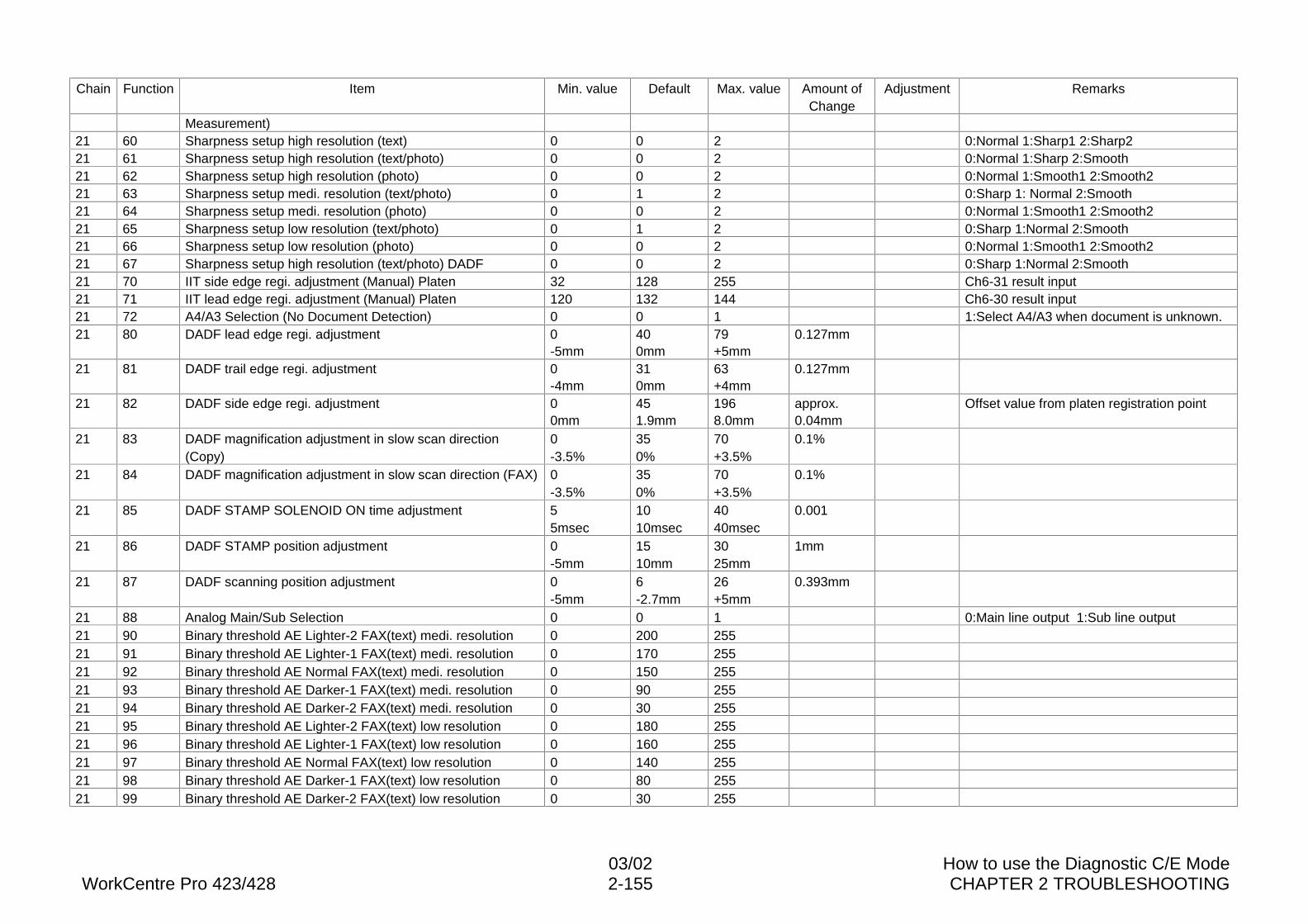
03/02 How to use the Diagnostic C/E ModeWorkCentre Pro 423/428 2-155 CHAPTER 2 TROUBLESHOOTING
Chain Function Item Min. value Default Max. value Amount ofChange
Adjustment Remarks
Measurement)21 60 Sharpness setup high resolution (text) 0 0 2 0:Normal 1:Sharp1 2:Sharp221 61 Sharpness setup high resolution (text/photo) 0 0 2 0:Normal 1:Sharp 2:Smooth21 62 Sharpness setup high resolution (photo) 0 0 2 0:Normal 1:Smooth1 2:Smooth221 63 Sharpness setup medi. resolution (text/photo) 0 1 2 0:Sharp 1: Normal 2:Smooth21 64 Sharpness setup medi. resolution (photo) 0 0 2 0:Normal 1:Smooth1 2:Smooth221 65 Sharpness setup low resolution (text/photo) 0 1 2 0:Sharp 1:Normal 2:Smooth21 66 Sharpness setup low resolution (photo) 0 0 2 0:Normal 1:Smooth1 2:Smooth221 67 Sharpness setup high resolution (text/photo) DADF 0 0 2 0:Sharp 1:Normal 2:Smooth21 70 IIT side edge regi. adjustment (Manual) Platen 32 128 255 Ch6-31 result input21 71 IIT lead edge regi. adjustment (Manual) Platen 120 132 144 Ch6-30 result input21 72 A4/A3 Selection (No Document Detection) 0 0 1 1:Select A4/A3 when document is unknown.21 80 DADF lead edge regi. adjustment 0
-5mm400mm
79+5mm
0.127mm
21 81 DADF trail edge regi. adjustment 0-4mm
310mm
63+4mm
0.127mm
21 82 DADF side edge regi. adjustment 00mm
451.9mm
1968.0mm
approx.0.04mm
Offset value from platen registration point
21 83 DADF magnification adjustment in slow scan direction(Copy)
0-3.5%
350%
70+3.5%
0.1%
21 84 DADF magnification adjustment in slow scan direction (FAX) 0-3.5%
350%
70+3.5%
0.1%
21 85 DADF STAMP SOLENOID ON time adjustment 55msec
1010msec
4040msec
0.001
21 86 DADF STAMP position adjustment 0-5mm
1510mm
3025mm
1mm
21 87 DADF scanning position adjustment 0-5mm
6-2.7mm
26+5mm
0.393mm
21 88 Analog Main/Sub Selection 0 0 1 0:Main line output 1:Sub line output21 90 Binary threshold AE Lighter-2 FAX(text) medi. resolution 0 200 25521 91 Binary threshold AE Lighter-1 FAX(text) medi. resolution 0 170 25521 92 Binary threshold AE Normal FAX(text) medi. resolution 0 150 25521 93 Binary threshold AE Darker-1 FAX(text) medi. resolution 0 90 25521 94 Binary threshold AE Darker-2 FAX(text) medi. resolution 0 30 25521 95 Binary threshold AE Lighter-2 FAX(text) low resolution 0 180 25521 96 Binary threshold AE Lighter-1 FAX(text) low resolution 0 160 25521 97 Binary threshold AE Normal FAX(text) low resolution 0 140 25521 98 Binary threshold AE Darker-1 FAX(text) low resolution 0 80 25521 99 Binary threshold AE Darker-2 FAX(text) low resolution 0 30 255
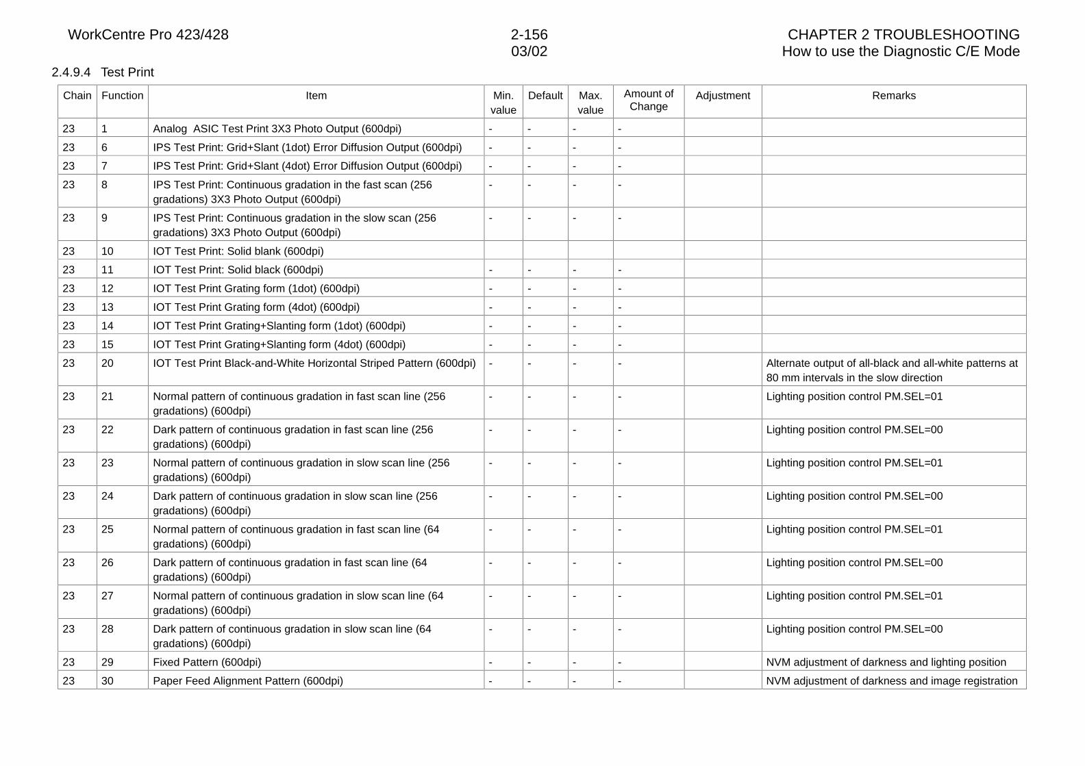
WorkCentre Pro 423/428 2-156 CHAPTER 2 TROUBLESHOOTING03/02 How to use the Diagnostic C/E Mode
2.4.9.4 Test Print
Chain Function Item Min.value
Default Max.value
Amount ofChange
Adjustment Remarks
23 1 Analog ASIC Test Print 3X3 Photo Output (600dpi) - - - -
23 6 IPS Test Print: Grid+Slant (1dot) Error Diffusion Output (600dpi) - - - -
23 7 IPS Test Print: Grid+Slant (4dot) Error Diffusion Output (600dpi) - - - -
23 8 IPS Test Print: Continuous gradation in the fast scan (256gradations) 3X3 Photo Output (600dpi)
- - - -
23 9 IPS Test Print: Continuous gradation in the slow scan (256gradations) 3X3 Photo Output (600dpi)
- - - -
23 10 IOT Test Print: Solid blank (600dpi)
23 11 IOT Test Print: Solid black (600dpi) - - - -
23 12 IOT Test Print Grating form (1dot) (600dpi) - - - -
23 13 IOT Test Print Grating form (4dot) (600dpi) - - - -
23 14 IOT Test Print Grating+Slanting form (1dot) (600dpi) - - - -
23 15 IOT Test Print Grating+Slanting form (4dot) (600dpi) - - - -
23 20 IOT Test Print Black-and-White Horizontal Striped Pattern (600dpi) - - - - Alternate output of all-black and all-white patterns at80 mm intervals in the slow direction
23 21 Normal pattern of continuous gradation in fast scan line (256gradations) (600dpi)
- - - - Lighting position control PM.SEL=01
23 22 Dark pattern of continuous gradation in fast scan line (256gradations) (600dpi)
- - - - Lighting position control PM.SEL=00
23 23 Normal pattern of continuous gradation in slow scan line (256gradations) (600dpi)
- - - - Lighting position control PM.SEL=01
23 24 Dark pattern of continuous gradation in slow scan line (256gradations) (600dpi)
- - - - Lighting position control PM.SEL=00
23 25 Normal pattern of continuous gradation in fast scan line (64gradations) (600dpi)
- - - - Lighting position control PM.SEL=01
23 26 Dark pattern of continuous gradation in fast scan line (64gradations) (600dpi)
- - - - Lighting position control PM.SEL=00
23 27 Normal pattern of continuous gradation in slow scan line (64gradations) (600dpi)
- - - - Lighting position control PM.SEL=01
23 28 Dark pattern of continuous gradation in slow scan line (64gradations) (600dpi)
- - - - Lighting position control PM.SEL=00
23 29 Fixed Pattern (600dpi) - - - - NVM adjustment of darkness and lighting position
23 30 Paper Feed Alignment Pattern (600dpi) - - - - NVM adjustment of darkness and image registration
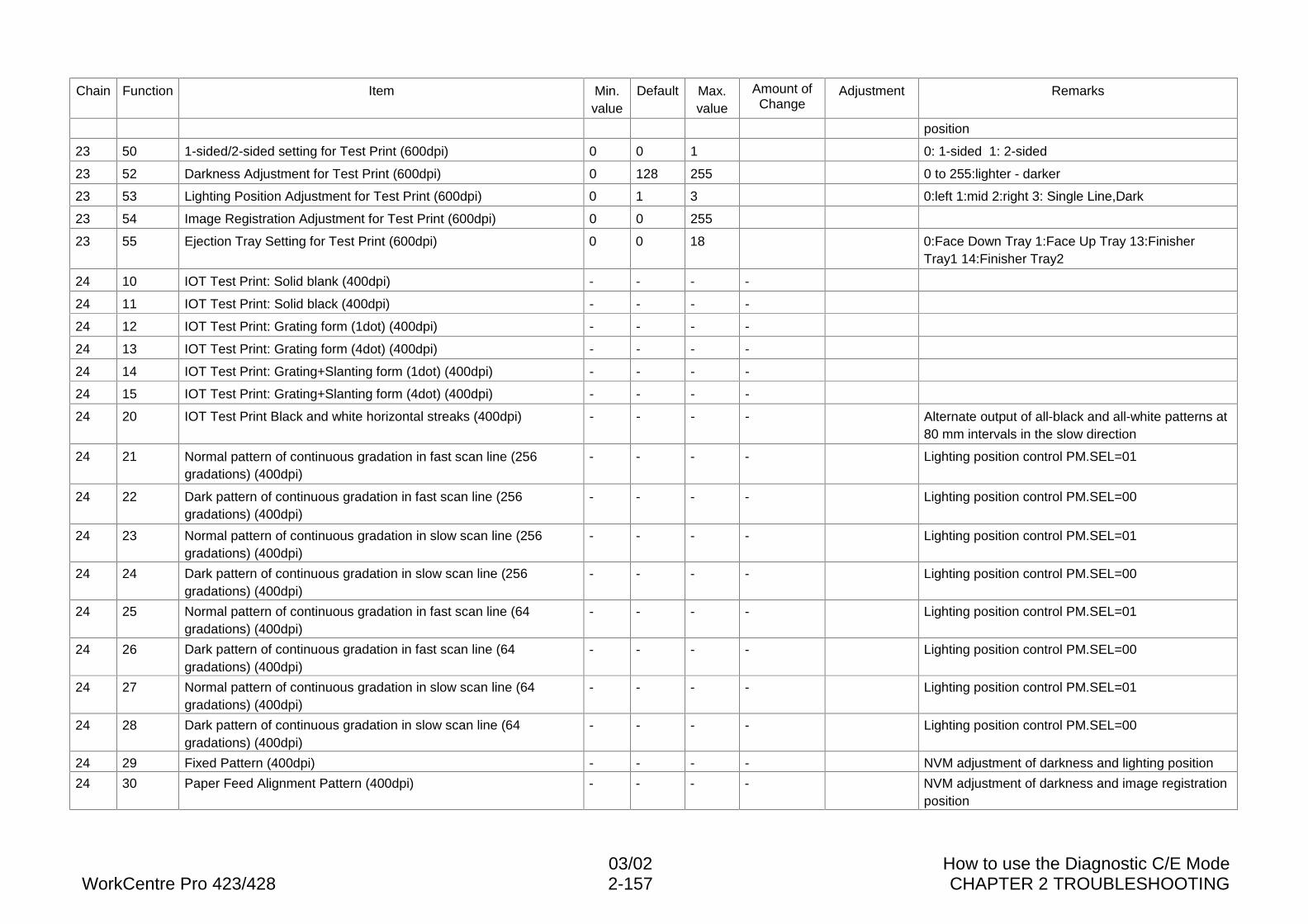
03/02 How to use the Diagnostic C/E ModeWorkCentre Pro 423/428 2-157 CHAPTER 2 TROUBLESHOOTING
Chain Function Item Min.value
Default Max.value
Amount ofChange
Adjustment Remarks
position
23 50 1-sided/2-sided setting for Test Print (600dpi) 0 0 1 0: 1-sided 1: 2-sided
23 52 Darkness Adjustment for Test Print (600dpi) 0 128 255 0 to 255:lighter - darker
23 53 Lighting Position Adjustment for Test Print (600dpi) 0 1 3 0:left 1:mid 2:right 3: Single Line,Dark
23 54 Image Registration Adjustment for Test Print (600dpi) 0 0 255
23 55 Ejection Tray Setting for Test Print (600dpi) 0 0 18 0:Face Down Tray 1:Face Up Tray 13:FinisherTray1 14:Finisher Tray2
24 10 IOT Test Print: Solid blank (400dpi) - - - -
24 11 IOT Test Print: Solid black (400dpi) - - - -
24 12 IOT Test Print: Grating form (1dot) (400dpi) - - - -
24 13 IOT Test Print: Grating form (4dot) (400dpi) - - - -
24 14 IOT Test Print: Grating+Slanting form (1dot) (400dpi) - - - -
24 15 IOT Test Print: Grating+Slanting form (4dot) (400dpi) - - - -
24 20 IOT Test Print Black and white horizontal streaks (400dpi) - - - - Alternate output of all-black and all-white patterns at80 mm intervals in the slow direction
24 21 Normal pattern of continuous gradation in fast scan line (256gradations) (400dpi)
- - - - Lighting position control PM.SEL=01
24 22 Dark pattern of continuous gradation in fast scan line (256gradations) (400dpi)
- - - - Lighting position control PM.SEL=00
24 23 Normal pattern of continuous gradation in slow scan line (256gradations) (400dpi)
- - - - Lighting position control PM.SEL=01
24 24 Dark pattern of continuous gradation in slow scan line (256gradations) (400dpi)
- - - - Lighting position control PM.SEL=00
24 25 Normal pattern of continuous gradation in fast scan line (64gradations) (400dpi)
- - - - Lighting position control PM.SEL=01
24 26 Dark pattern of continuous gradation in fast scan line (64gradations) (400dpi)
- - - - Lighting position control PM.SEL=00
24 27 Normal pattern of continuous gradation in slow scan line (64gradations) (400dpi)
- - - - Lighting position control PM.SEL=01
24 28 Dark pattern of continuous gradation in slow scan line (64gradations) (400dpi)
- - - - Lighting position control PM.SEL=00
24 29 Fixed Pattern (400dpi) - - - - NVM adjustment of darkness and lighting position
24 30 Paper Feed Alignment Pattern (400dpi) - - - - NVM adjustment of darkness and image registrationposition
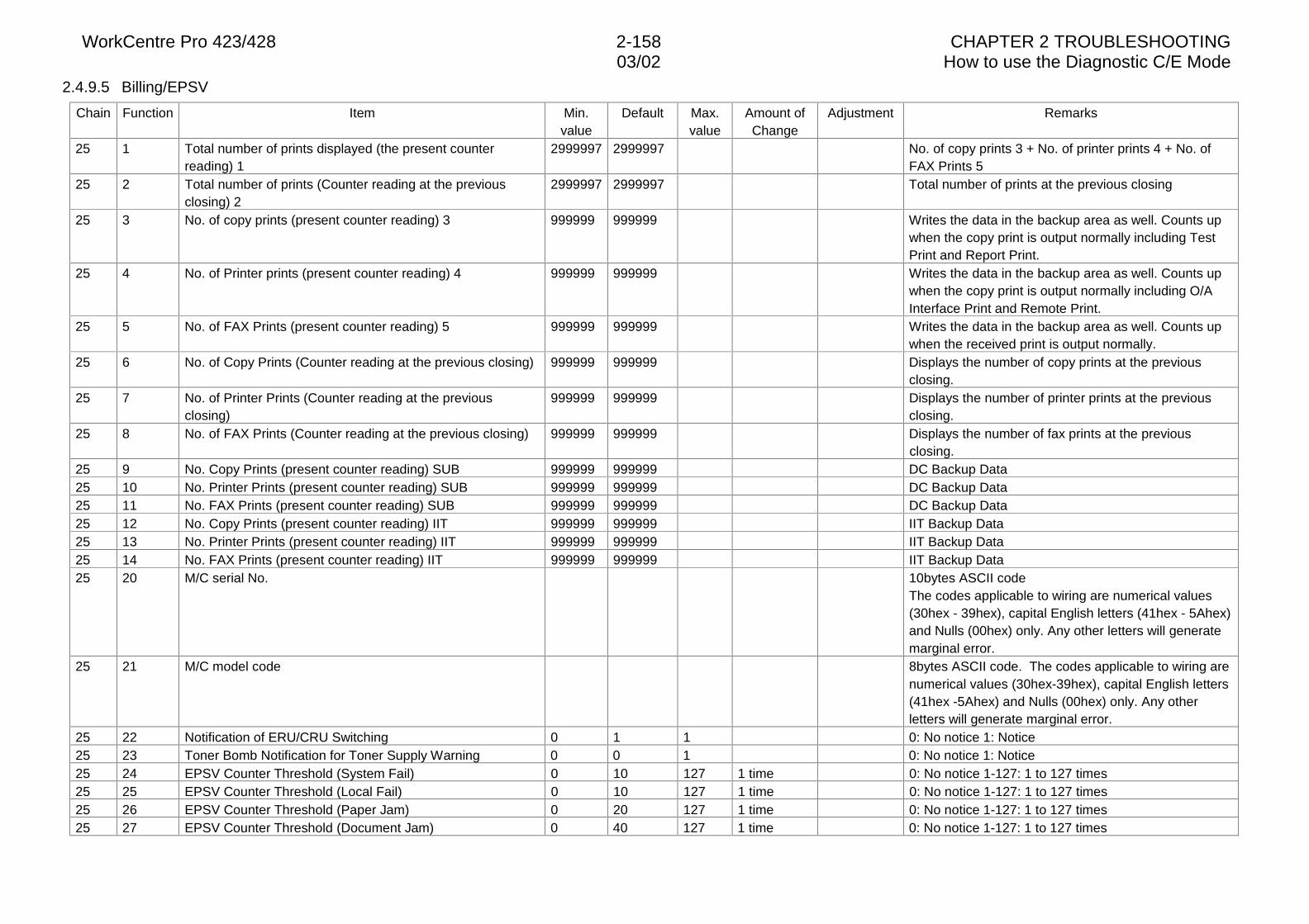
WorkCentre Pro 423/428 2-158 CHAPTER 2 TROUBLESHOOTING03/02 How to use the Diagnostic C/E Mode
2.4.9.5 Billing/EPSV
Chain Function Item Min.value
Default Max.value
Amount ofChange
Adjustment Remarks
25 1 Total number of prints displayed (the present counterreading) 1
2999997 2999997 No. of copy prints 3 + No. of printer prints 4 + No. ofFAX Prints 5
25 2 Total number of prints (Counter reading at the previousclosing) 2
2999997 2999997 Total number of prints at the previous closing
25 3 No. of copy prints (present counter reading) 3 999999 999999 Writes the data in the backup area as well. Counts upwhen the copy print is output normally including TestPrint and Report Print.
25 4 No. of Printer prints (present counter reading) 4 999999 999999 Writes the data in the backup area as well. Counts upwhen the copy print is output normally including O/AInterface Print and Remote Print.
25 5 No. of FAX Prints (present counter reading) 5 999999 999999 Writes the data in the backup area as well. Counts upwhen the received print is output normally.
25 6 No. of Copy Prints (Counter reading at the previous closing) 999999 999999 Displays the number of copy prints at the previousclosing.
25 7 No. of Printer Prints (Counter reading at the previousclosing)
999999 999999 Displays the number of printer prints at the previousclosing.
25 8 No. of FAX Prints (Counter reading at the previous closing) 999999 999999 Displays the number of fax prints at the previousclosing.
25 9 No. Copy Prints (present counter reading) SUB 999999 999999 DC Backup Data25 10 No. Printer Prints (present counter reading) SUB 999999 999999 DC Backup Data25 11 No. FAX Prints (present counter reading) SUB 999999 999999 DC Backup Data25 12 No. Copy Prints (present counter reading) IIT 999999 999999 IIT Backup Data25 13 No. Printer Prints (present counter reading) IIT 999999 999999 IIT Backup Data25 14 No. FAX Prints (present counter reading) IIT 999999 999999 IIT Backup Data25 20 M/C serial No. 10bytes ASCII code
The codes applicable to wiring are numerical values(30hex - 39hex), capital English letters (41hex - 5Ahex)and Nulls (00hex) only. Any other letters will generatemarginal error.
25 21 M/C model code 8bytes ASCII code. The codes applicable to wiring arenumerical values (30hex-39hex), capital English letters(41hex -5Ahex) and Nulls (00hex) only. Any otherletters will generate marginal error.
25 22 Notification of ERU/CRU Switching 0 1 1 0: No notice 1: Notice25 23 Toner Bomb Notification for Toner Supply Warning 0 0 1 0: No notice 1: Notice25 24 EPSV Counter Threshold (System Fail) 0 10 127 1 time 0: No notice 1-127: 1 to 127 times25 25 EPSV Counter Threshold (Local Fail) 0 10 127 1 time 0: No notice 1-127: 1 to 127 times25 26 EPSV Counter Threshold (Paper Jam) 0 20 127 1 time 0: No notice 1-127: 1 to 127 times25 27 EPSV Counter Threshold (Document Jam) 0 40 127 1 time 0: No notice 1-127: 1 to 127 times
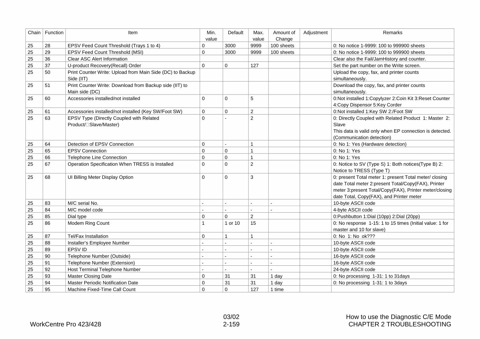
03/02 How to use the Diagnostic C/E ModeWorkCentre Pro 423/428 2-159 CHAPTER 2 TROUBLESHOOTING
Chain Function Item Min.value
Default Max.value
Amount ofChange
Adjustment Remarks
25 28 EPSV Feed Count Threshold (Trays 1 to 4) 0 3000 9999 100 sheets 0: No notice 1-9999: 100 to 999900 sheets25 29 EPSV Feed Count Threshold (MSI) 0 3000 9999 100 sheets 0: No notice 1-9999: 100 to 999900 sheets25 36 Clear ASC Alert Information Clear also the Fail/JamHistory and counter.25 37 U-product Recovery(Recall) Order 0 0 127 Set the part number on the Write screen.25 50 Print Counter Write: Upload from Main Side (DC) to Backup
Side (IIT)Upload the copy, fax, and printer countssimultaneously.
25 51 Print Counter Write: Download from Backup side (IIT) toMain side (DC)
Download the copy, fax, and printer countssimultaneously.
25 60 Accessories installed/not installed 0 0 5 0:Not installed 1:Copylyzer 2:Coin Kit 3:Reset Counter4:Copy Dispensor 5:Key Corder
25 61 Accessories installed/not installed (Key SW/Foot SW) 0 0 2 0:Not installed 1:Key SW 2:/Foot SW25 63 EPSV Type (Directly Coupled with Related
Product/�Slave/Master)0 - 2 0: Directly Coupled with Related Product 1: Master 2:
SlaveThis data is valid only when EP connection is detected.(Communication detection)
25 64 Detection of EPSV Connection 0 - 1 0: No 1: Yes (Hardware detection)25 65 EPSV Connection 0 0 1 0: No 1: Yes25 66 Telephone Line Connection 0 0 1 0: No 1: Yes25 67 Operation Specification When TRESS is Installed 0 0 2 0: Notice to SV (Type S) 1: Both notices(Type B) 2:
Notice to TRESS (Type T)25 68 UI Billing Meter Display Option 0 0 3 0: present Total meter 1: present Total meter/ closing
date Total meter 2:present Total/Copy(FAX), Printermeter 3:present Total/Copy(FAX), Printer meter/closingdate Total, Copy(FAX), and Printer meter
25 83 M/C serial No. - - - - 10-byte ASCII code25 84 M/C model code - - - - 4-byte ASCII code25 85 Dial type 0 0 2 0:Pushbutton 1:Dial (10pp) 2:Dial (20pp)25 86 Modem Ring Count 1 1 or 10 15 0: No response 1-15: 1 to 15 times (Initial value: 1 for
master and 10 for slave)25 87 Tel/Fax Installation 0 1 1 0: No 1: No ok???25 88 Installer’s Employee Number - - - - 10-byte ASCII code25 89 EPSV ID - - - - 10-byte ASCII code25 90 Telephone Number (Outside) - - - - 16-byte ASCII code25 91 Telephone Number (Extension) - - - - 16-byte ASCII code25 92 Host Terminal Telephone Number - - - - 24-byte ASCII code25 93 Master Closing Date 0 31 31 1 day 0: No processing 1-31: 1 to 31days25 94 Master Periodic Notification Date 0 31 31 1 day 0: No processing 1-31: 1 to 3days25 95 Machine Fixed-Time Call Count 0 0 127 1 time
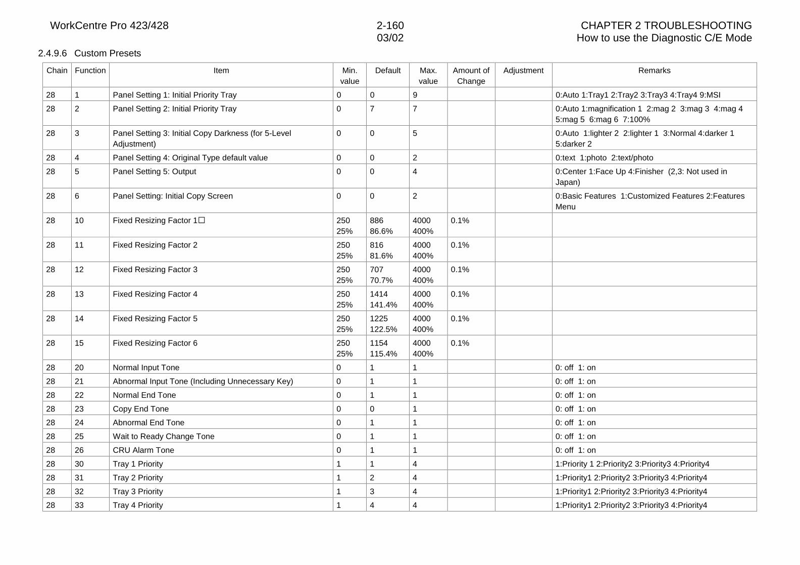
WorkCentre Pro 423/428 2-160 CHAPTER 2 TROUBLESHOOTING03/02 How to use the Diagnostic C/E Mode
2.4.9.6 Custom Presets
Chain Function Item Min.value
Default Max.value
Amount ofChange
Adjustment Remarks
28 1 Panel Setting 1: Initial Priority Tray 0 0 9 0:Auto 1:Tray1 2:Tray2 3:Tray3 4:Tray4 9:MSI
28 2 Panel Setting 2: Initial Priority Tray 0 7 7 0:Auto 1:magnification 1 2:mag 2 3:mag 3 4:mag 45:mag 5 6:mag 6 7:100%
28 3 Panel Setting 3: Initial Copy Darkness (for 5-LevelAdjustment)
0 0 5 0:Auto 1:lighter 2 2:lighter 1 3:Normal 4:darker 15:darker 2
28 4 Panel Setting 4: Original Type default value 0 0 2 0:text 1:photo 2:text/photo
28 5 Panel Setting 5: Output 0 0 4 0:Center 1:Face Up 4:Finisher (2,3: Not used inJapan)
28 6 Panel Setting: Initial Copy Screen 0 0 2 0:Basic Features 1:Customized Features 2:FeaturesMenu
28 10 Fixed Resizing Factor 1� 25025%
88686.6%
4000400%
0.1%
28 11 Fixed Resizing Factor 2 25025%
81681.6%
4000400%
0.1%
28 12 Fixed Resizing Factor 3 25025%
70770.7%
4000400%
0.1%
28 13 Fixed Resizing Factor 4 25025%
1414141.4%
4000400%
0.1%
28 14 Fixed Resizing Factor 5 25025%
1225122.5%
4000400%
0.1%
28 15 Fixed Resizing Factor 6 25025%
1154115.4%
4000400%
0.1%
28 20 Normal Input Tone 0 1 1 0: off 1: on
28 21 Abnormal Input Tone (Including Unnecessary Key) 0 1 1 0: off 1: on
28 22 Normal End Tone 0 1 1 0: off 1: on
28 23 Copy End Tone 0 0 1 0: off 1: on
28 24 Abnormal End Tone 0 1 1 0: off 1: on
28 25 Wait to Ready Change Tone 0 1 1 0: off 1: on
28 26 CRU Alarm Tone 0 1 1 0: off 1: on
28 30 Tray 1 Priority 1 1 4 1:Priority 1 2:Priority2 3:Priority3 4:Priority4
28 31 Tray 2 Priority 1 2 4 1:Priority1 2:Priority2 3:Priority3 4:Priority4
28 32 Tray 3 Priority 1 3 4 1:Priority1 2:Priority2 3:Priority3 4:Priority4
28 33 Tray 4 Priority 1 4 4 1:Priority1 2:Priority2 3:Priority3 4:Priority4
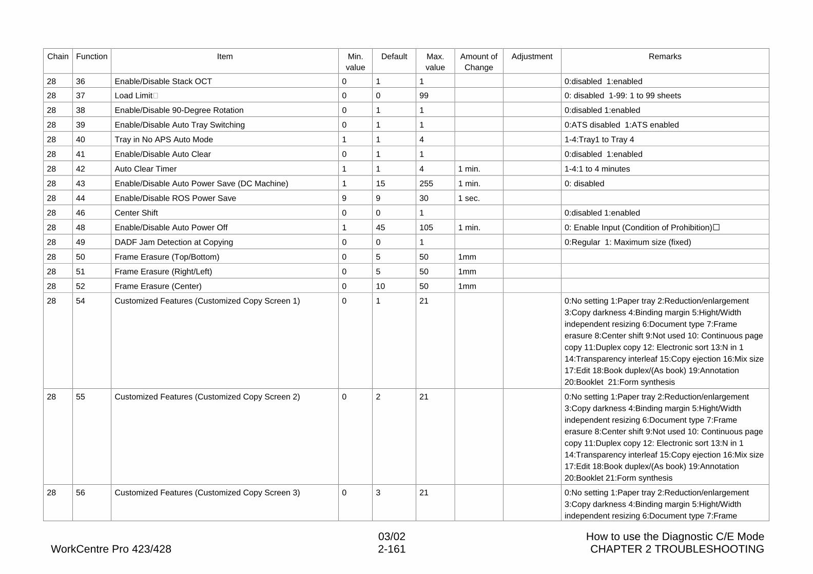
03/02 How to use the Diagnostic C/E ModeWorkCentre Pro 423/428 2-161 CHAPTER 2 TROUBLESHOOTING
Chain Function Item Min.value
Default Max.value
Amount ofChange
Adjustment Remarks
28 36 Enable/Disable Stack OCT 0 1 1 0:disabled 1:enabled
28 37 Load Limit� 0 0 99 0: disabled 1-99: 1 to 99 sheets
28 38 Enable/Disable 90-Degree Rotation 0 1 1 0:disabled 1:enabled
28 39 Enable/Disable Auto Tray Switching 0 1 1 0:ATS disabled 1:ATS enabled
28 40 Tray in No APS Auto Mode 1 1 4 1-4:Tray1 to Tray 4
28 41 Enable/Disable Auto Clear 0 1 1 0:disabled 1:enabled
28 42 Auto Clear Timer 1 1 4 1 min. 1-4:1 to 4 minutes
28 43 Enable/Disable Auto Power Save (DC Machine) 1 15 255 1 min. 0: disabled
28 44 Enable/Disable ROS Power Save 9 9 30 1 sec.
28 46 Center Shift 0 0 1 0:disabled 1:enabled
28 48 Enable/Disable Auto Power Off 1 45 105 1 min. 0: Enable Input (Condition of Prohibition)�
28 49 DADF Jam Detection at Copying 0 0 1 0:Regular 1: Maximum size (fixed)
28 50 Frame Erasure (Top/Bottom) 0 5 50 1mm
28 51 Frame Erasure (Right/Left) 0 5 50 1mm
28 52 Frame Erasure (Center) 0 10 50 1mm
28 54 Customized Features (Customized Copy Screen 1) 0 1 21 0:No setting 1:Paper tray 2:Reduction/enlargement3:Copy darkness 4:Binding margin 5:Hight/Widthindependent resizing 6:Document type 7:Frameerasure 8:Center shift 9:Not used 10: Continuous pagecopy 11:Duplex copy 12: Electronic sort 13:N in 114:Transparency interleaf 15:Copy ejection 16:Mix size17:Edit 18:Book duplex/(As book) 19:Annotation20:Booklet 21:Form synthesis
28 55 Customized Features (Customized Copy Screen 2) 0 2 21 0:No setting 1:Paper tray 2:Reduction/enlargement3:Copy darkness 4:Binding margin 5:Hight/Widthindependent resizing 6:Document type 7:Frameerasure 8:Center shift 9:Not used 10: Continuous pagecopy 11:Duplex copy 12: Electronic sort 13:N in 114:Transparency interleaf 15:Copy ejection 16:Mix size17:Edit 18:Book duplex/(As book) 19:Annotation20:Booklet 21:Form synthesis
28 56 Customized Features (Customized Copy Screen 3) 0 3 21 0:No setting 1:Paper tray 2:Reduction/enlargement3:Copy darkness 4:Binding margin 5:Hight/Widthindependent resizing 6:Document type 7:Frame
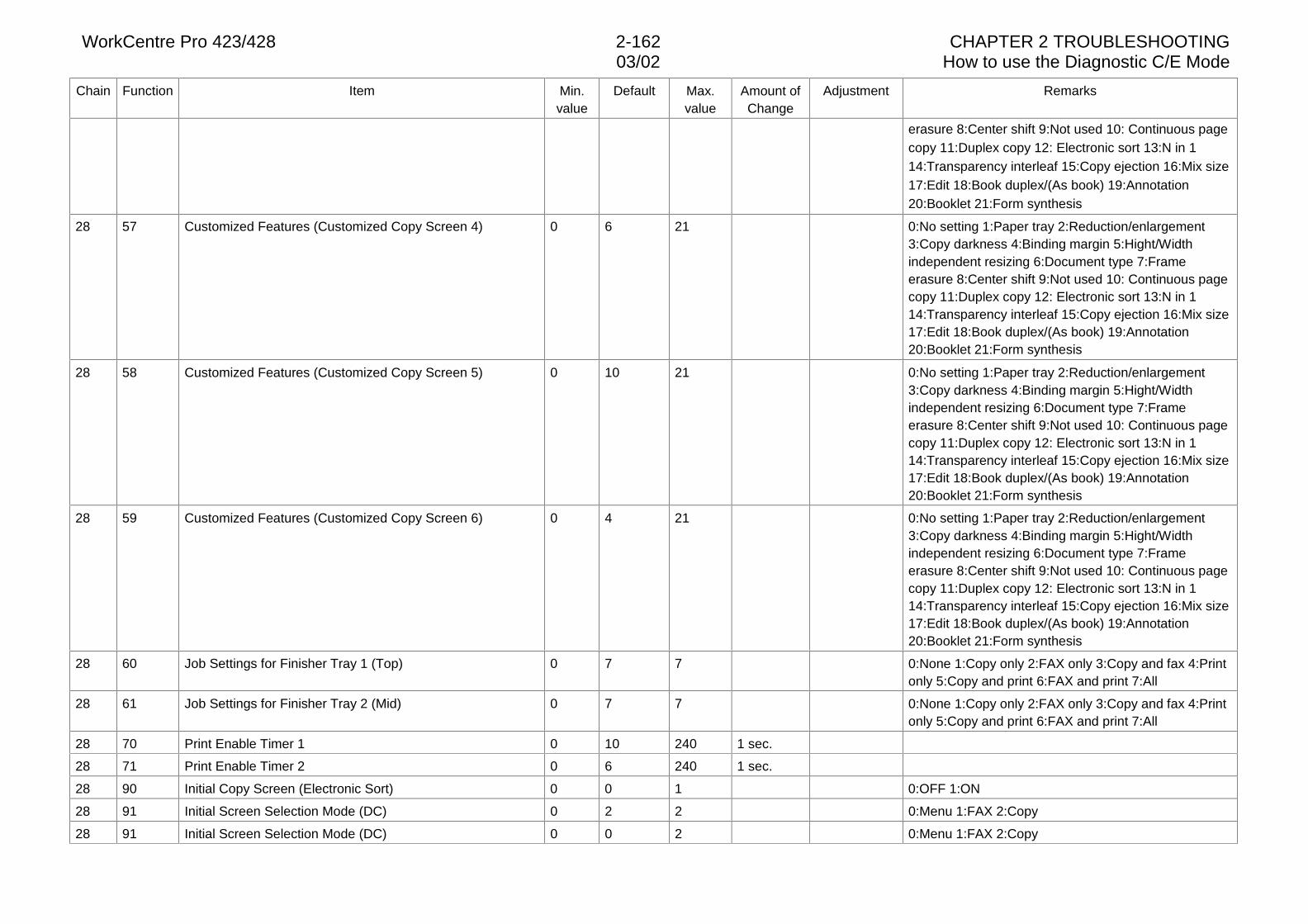
WorkCentre Pro 423/428 2-162 CHAPTER 2 TROUBLESHOOTING03/02 How to use the Diagnostic C/E Mode
Chain Function Item Min.value
Default Max.value
Amount ofChange
Adjustment Remarks
erasure 8:Center shift 9:Not used 10: Continuous pagecopy 11:Duplex copy 12: Electronic sort 13:N in 114:Transparency interleaf 15:Copy ejection 16:Mix size17:Edit 18:Book duplex/(As book) 19:Annotation20:Booklet 21:Form synthesis
28 57 Customized Features (Customized Copy Screen 4) 0 6 21 0:No setting 1:Paper tray 2:Reduction/enlargement3:Copy darkness 4:Binding margin 5:Hight/Widthindependent resizing 6:Document type 7:Frameerasure 8:Center shift 9:Not used 10: Continuous pagecopy 11:Duplex copy 12: Electronic sort 13:N in 114:Transparency interleaf 15:Copy ejection 16:Mix size17:Edit 18:Book duplex/(As book) 19:Annotation20:Booklet 21:Form synthesis
28 58 Customized Features (Customized Copy Screen 5) 0 10 21 0:No setting 1:Paper tray 2:Reduction/enlargement3:Copy darkness 4:Binding margin 5:Hight/Widthindependent resizing 6:Document type 7:Frameerasure 8:Center shift 9:Not used 10: Continuous pagecopy 11:Duplex copy 12: Electronic sort 13:N in 114:Transparency interleaf 15:Copy ejection 16:Mix size17:Edit 18:Book duplex/(As book) 19:Annotation20:Booklet 21:Form synthesis
28 59 Customized Features (Customized Copy Screen 6) 0 4 21 0:No setting 1:Paper tray 2:Reduction/enlargement3:Copy darkness 4:Binding margin 5:Hight/Widthindependent resizing 6:Document type 7:Frameerasure 8:Center shift 9:Not used 10: Continuous pagecopy 11:Duplex copy 12: Electronic sort 13:N in 114:Transparency interleaf 15:Copy ejection 16:Mix size17:Edit 18:Book duplex/(As book) 19:Annotation20:Booklet 21:Form synthesis
28 60 Job Settings for Finisher Tray 1 (Top) 0 7 7 0:None 1:Copy only 2:FAX only 3:Copy and fax 4:Printonly 5:Copy and print 6:FAX and print 7:All
28 61 Job Settings for Finisher Tray 2 (Mid) 0 7 7 0:None 1:Copy only 2:FAX only 3:Copy and fax 4:Printonly 5:Copy and print 6:FAX and print 7:All
28 70 Print Enable Timer 1 0 10 240 1 sec.
28 71 Print Enable Timer 2 0 6 240 1 sec.
28 90 Initial Copy Screen (Electronic Sort) 0 0 1 0:OFF 1:ON
28 91 Initial Screen Selection Mode (DC) 0 2 2 0:Menu 1:FAX 2:Copy
28 91 Initial Screen Selection Mode (DC) 0 0 2 0:Menu 1:FAX 2:Copy
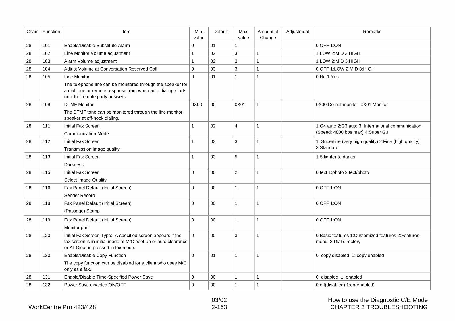
03/02 How to use the Diagnostic C/E ModeWorkCentre Pro 423/428 2-163 CHAPTER 2 TROUBLESHOOTING
Chain Function Item Min.value
Default Max.value
Amount ofChange
Adjustment Remarks
28 101 Enable/Disable Substitute Alarm 0 01 1 0:OFF 1:ON
28 102 Line Monitor Volume adjustment 1 02 3 1 1:LOW 2:MID 3:HIGH
28 103 Alarm Volume adjustment 1 02 3 1 1:LOW 2:MID 3:HIGH
28 104 Adjust Volume at Conversation Reserved Call 0 03 3 1 0:OFF 1:LOW 2:MID 3:HIGH
28 105 Line Monitor
The telephone line can be monitored through the speaker fora dial tone or remote response from when auto dialing startsuntil the remote party answers.
0 01 1 1 0:No 1:Yes
28 108 DTMF Monitor
The DTMF tone can be monitored through the line monitorspeaker at off-hook dialing.
0X00 00 0X01 1 0X00:Do not monitor 0X01:Monitor
28 111 Initial Fax Screen
Communication Mode
1 02 4 1 1:G4 auto 2:G3 auto 3: International communication(Speed: 4800 bps max) 4:Super G3
28 112 Initial Fax Screen
Transmission image quality
1 03 3 1 1: Superfine (very high quality) 2:Fine (high quality)3:Standard
28 113 Initial Fax Screen
Darkness
1 03 5 1 1-5:lighter to darker
28 115 Initial Fax Screen
Select Image Quality
0 00 2 1 0:text 1:photo 2:text/photo
28 116 Fax Panel Default (Initial Screen)
Sender Record
0 00 1 1 0:OFF 1:ON
28 118 Fax Panel Default (Initial Screen)
(Passage) Stamp
0 00 1 1 0:OFF 1:ON
28 119 Fax Panel Default (Initial Screen)
Monitor print
0 00 1 1 0:OFF 1:ON
28 120 Initial Fax Screen Type: A specified screen appears if thefax screen is in initial mode at M/C boot-up or auto clearanceor All Clear is pressed in fax mode.
0 00 3 1 0:Basic features 1:Customized features 2:Featuresmeau 3:Dial directory
28 130 Enable/Disable Copy Function
The copy function can be disabled for a client who uses M/Conly as a fax.
0 01 1 1 0: copy disabled 1: copy enabled
28 131 Enable/Disable Time-Specified Power Save 0 00 1 1 0: disabled 1: enabled
28 132 Power Save disabled ON/OFF 0 00 1 1 0:off(disabled) 1:on(enabled)
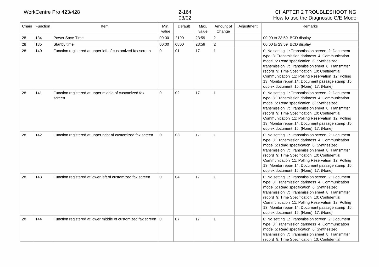
WorkCentre Pro 423/428 2-164 CHAPTER 2 TROUBLESHOOTING03/02 How to use the Diagnostic C/E Mode
Chain Function Item Min.value
Default Max.value
Amount ofChange
Adjustment Remarks
28 134 Power Save Time 00:00 2100 23:59 2 00:00 to 23:59 BCD display
28 135 Stanby time 00:00 0800 23:59 2 00:00 to 23:59 BCD display
28 140 Function registered at upper left of customized fax screen 0 01 17 1 0: No setting 1: Transmission screen 2: Documenttype 3: Transmission darkness 4: Communicationmode 5: Read specification 6: Synthesizedtransmission 7: Transmission sheet 8: Transmitterrecord 9: Time Specification 10: ConfidentialCommunication 11: Polling Reservation 12: Polling13: Monitor report 14: Document passage stamp 15:duplex document 16: (None) 17: (None)
28 141 Function registered at upper middle of customized faxscreen
0 02 17 1 0: No setting 1: Transmission screen 2: Documenttype 3: Transmission darkness 4: Communicationmode 5: Read specification 6: Synthesizedtransmission 7: Transmission sheet 8: Transmitterrecord 9: Time Specification 10: ConfidentialCommunication 11: Polling Reservation 12: Polling13: Monitor report 14: Document passage stamp 15:duplex document 16: (None) 17: (None)
28 142 Function registered at upper right of customized fax screen 0 03 17 1 0: No setting 1: Transmission screen 2: Documenttype 3: Transmission darkness 4: Communicationmode 5: Read specification 6: Synthesizedtransmission 7: Transmission sheet 8: Transmitterrecord 9: Time Specification 10: ConfidentialCommunication 11: Polling Reservation 12: Polling13: Monitor report 14: Document passage stamp 15:duplex document 16: (None) 17: (None)
28 143 Function registered at lower left of customized fax screen 0 04 17 1 0: No setting 1: Transmission screen 2: Documenttype 3: Transmission darkness 4: Communicationmode 5: Read specification 6: Synthesizedtransmission 7: Transmission sheet 8: Transmitterrecord 9: Time Specification 10: ConfidentialCommunication 11: Polling Reservation 12: Polling13: Monitor report 14: Document passage stamp 15:duplex document 16: (None) 17: (None)
28 144 Function registered at lower middle of customized fax screen 0 07 17 1 0: No setting 1: Transmission screen 2: Documenttype 3: Transmission darkness 4: Communicationmode 5: Read specification 6: Synthesizedtransmission 7: Transmission sheet 8: Transmitterrecord 9: Time Specification 10: Confidential
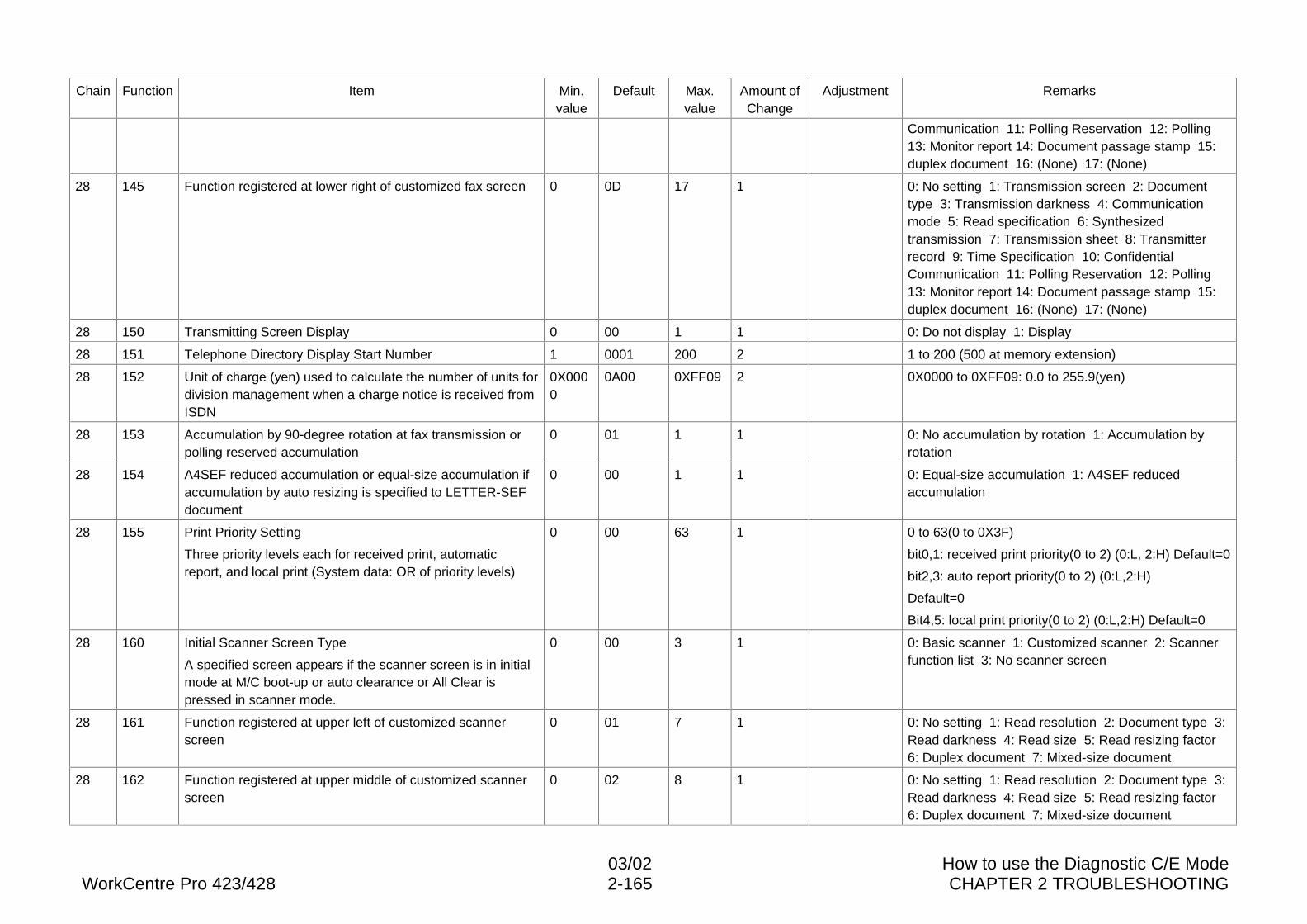
03/02 How to use the Diagnostic C/E ModeWorkCentre Pro 423/428 2-165 CHAPTER 2 TROUBLESHOOTING
Chain Function Item Min.value
Default Max.value
Amount ofChange
Adjustment Remarks
Communication 11: Polling Reservation 12: Polling13: Monitor report 14: Document passage stamp 15:duplex document 16: (None) 17: (None)
28 145 Function registered at lower right of customized fax screen 0 0D 17 1 0: No setting 1: Transmission screen 2: Documenttype 3: Transmission darkness 4: Communicationmode 5: Read specification 6: Synthesizedtransmission 7: Transmission sheet 8: Transmitterrecord 9: Time Specification 10: ConfidentialCommunication 11: Polling Reservation 12: Polling13: Monitor report 14: Document passage stamp 15:duplex document 16: (None) 17: (None)
28 150 Transmitting Screen Display 0 00 1 1 0: Do not display 1: Display
28 151 Telephone Directory Display Start Number 1 0001 200 2 1 to 200 (500 at memory extension)
28 152 Unit of charge (yen) used to calculate the number of units fordivision management when a charge notice is received fromISDN
0X0000
0A00 0XFF09 2 0X0000 to 0XFF09: 0.0 to 255.9(yen)
28 153 Accumulation by 90-degree rotation at fax transmission orpolling reserved accumulation
0 01 1 1 0: No accumulation by rotation 1: Accumulation byrotation
28 154 A4SEF reduced accumulation or equal-size accumulation ifaccumulation by auto resizing is specified to LETTER-SEFdocument
0 00 1 1 0: Equal-size accumulation 1: A4SEF reducedaccumulation
28 155 Print Priority Setting
Three priority levels each for received print, automaticreport, and local print (System data: OR of priority levels)
0 00 63 1 0 to 63(0 to 0X3F)
bit0,1: received print priority(0 to 2) (0:L, 2:H) Default=0
bit2,3: auto report priority(0 to 2) (0:L,2:H)
Default=0
Bit4,5: local print priority(0 to 2) (0:L,2:H) Default=0
28 160 Initial Scanner Screen Type
A specified screen appears if the scanner screen is in initialmode at M/C boot-up or auto clearance or All Clear ispressed in scanner mode.
0 00 3 1 0: Basic scanner 1: Customized scanner 2: Scannerfunction list 3: No scanner screen
28 161 Function registered at upper left of customized scannerscreen
0 01 7 1 0: No setting 1: Read resolution 2: Document type 3:Read darkness 4: Read size 5: Read resizing factor6: Duplex document 7: Mixed-size document
28 162 Function registered at upper middle of customized scannerscreen
0 02 8 1 0: No setting 1: Read resolution 2: Document type 3:Read darkness 4: Read size 5: Read resizing factor6: Duplex document 7: Mixed-size document
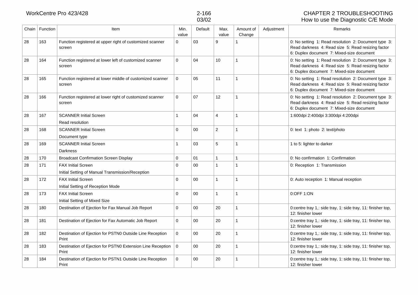
WorkCentre Pro 423/428 2-166 CHAPTER 2 TROUBLESHOOTING03/02 How to use the Diagnostic C/E Mode
Chain Function Item Min.value
Default Max.value
Amount ofChange
Adjustment Remarks
28 163 Function registered at upper right of customized scannerscreen
0 03 9 1 0: No setting 1: Read resolution 2: Document type 3:Read darkness 4: Read size 5: Read resizing factor6: Duplex document 7: Mixed-size document
28 164 Function registered at lower left of customized scannerscreen
0 04 10 1 0: No setting 1: Read resolution 2: Document type 3:Read darkness 4: Read size 5: Read resizing factor6: Duplex document 7: Mixed-size document
28 165 Function registered at lower middle of customized scannerscreen
0 05 11 1 0: No setting 1: Read resolution 2: Document type 3:Read darkness 4: Read size 5: Read resizing factor6: Duplex document 7: Mixed-size document
28 166 Function registered at lower right of customized scannerscreen
0 07 12 1 0: No setting 1: Read resolution 2: Document type 3:Read darkness 4: Read size 5: Read resizing factor6: Duplex document 7: Mixed-size document
28 167 SCANNER Initial Screen
Read resolution
1 04 4 1 1:600dpi 2:400dpi 3:300dpi 4:200dpi
28 168 SCANNER Initial Screen
Document type
0 00 2 1 0: text 1: photo 2: text/photo
28 169 SCANNER Initial Screen
Darkness
1 03 5 1 1 to 5: lighter to darker
28 170 Broadcast Confirmation Screen Display 0 01 1 1 0: No confirmation 1: Confirmation
28 171 FAX Initial Screen
Initial Setting of Manual Transmission/Reception
0 00 1 1 0: Reception 1: Transmission
28 172 FAX Initial Screen
Initial Setting of Reception Mode
0 00 1 1 0: Auto reception 1: Manual reception
28 173 FAX Initial Screen
Initial Setting of Mixed Size
0 00 1 1 0:OFF 1:ON
28 180 Destination of Ejection for Fax Manual Job Report 0 00 20 1 0:centre tray 1,: side tray, 1: side tray, 11: finisher top,12: finisher lower
28 181 Destination of Ejection for Fax Automatic Job Report 0 00 20 1 0:centre tray 1,: side tray, 1: side tray, 11: finisher top,12: finisher lower
28 182 Destination of Ejection for PSTN0 Outside Line ReceptionPrint
0 00 20 1 0:centre tray 1,: side tray, 1: side tray, 11: finisher top,12: finisher lower
28 183 Destination of Ejection for PSTN0 Extension Line ReceptionPrint
0 00 20 1 0:centre tray 1,: side tray, 1: side tray, 11: finisher top,12: finisher lower
28 184 Destination of Ejection for PSTN1 Outside Line ReceptionPrint
0 00 20 1 0:centre tray 1,: side tray, 1: side tray, 11: finisher top,12: finisher lower
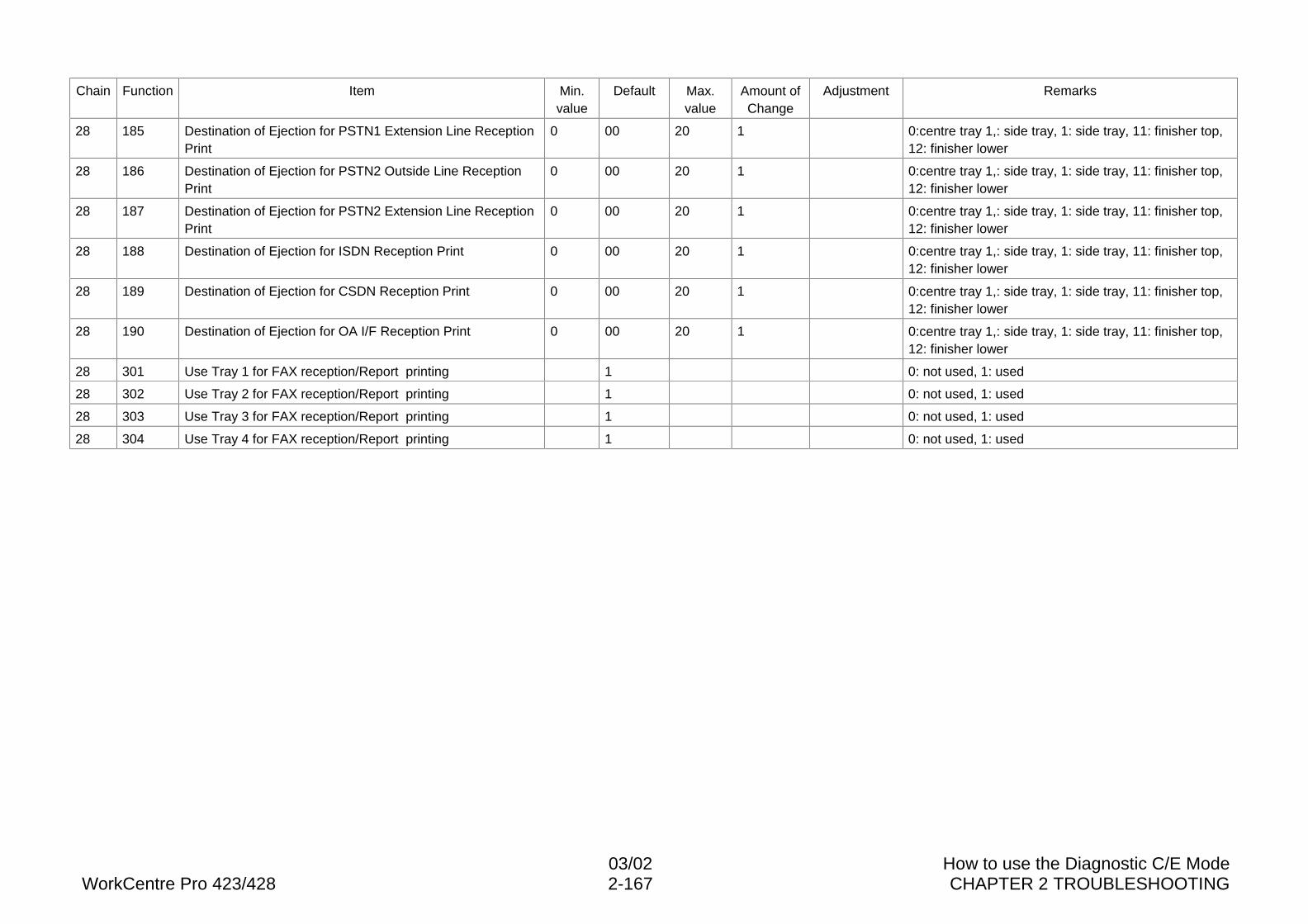
03/02 How to use the Diagnostic C/E ModeWorkCentre Pro 423/428 2-167 CHAPTER 2 TROUBLESHOOTING
Chain Function Item Min.value
Default Max.value
Amount ofChange
Adjustment Remarks
28 185 Destination of Ejection for PSTN1 Extension Line ReceptionPrint
0 00 20 1 0:centre tray 1,: side tray, 1: side tray, 11: finisher top,12: finisher lower
28 186 Destination of Ejection for PSTN2 Outside Line ReceptionPrint
0 00 20 1 0:centre tray 1,: side tray, 1: side tray, 11: finisher top,12: finisher lower
28 187 Destination of Ejection for PSTN2 Extension Line ReceptionPrint
0 00 20 1 0:centre tray 1,: side tray, 1: side tray, 11: finisher top,12: finisher lower
28 188 Destination of Ejection for ISDN Reception Print 0 00 20 1 0:centre tray 1,: side tray, 1: side tray, 11: finisher top,12: finisher lower
28 189 Destination of Ejection for CSDN Reception Print 0 00 20 1 0:centre tray 1,: side tray, 1: side tray, 11: finisher top,12: finisher lower
28 190 Destination of Ejection for OA I/F Reception Print 0 00 20 1 0:centre tray 1,: side tray, 1: side tray, 11: finisher top,12: finisher lower
28 301 Use Tray 1 for FAX reception/Report printing 1 0: not used, 1: used
28 302 Use Tray 2 for FAX reception/Report printing 1 0: not used, 1: used
28 303 Use Tray 3 for FAX reception/Report printing 1 0: not used, 1: used
28 304 Use Tray 4 for FAX reception/Report printing 1 0: not used, 1: used
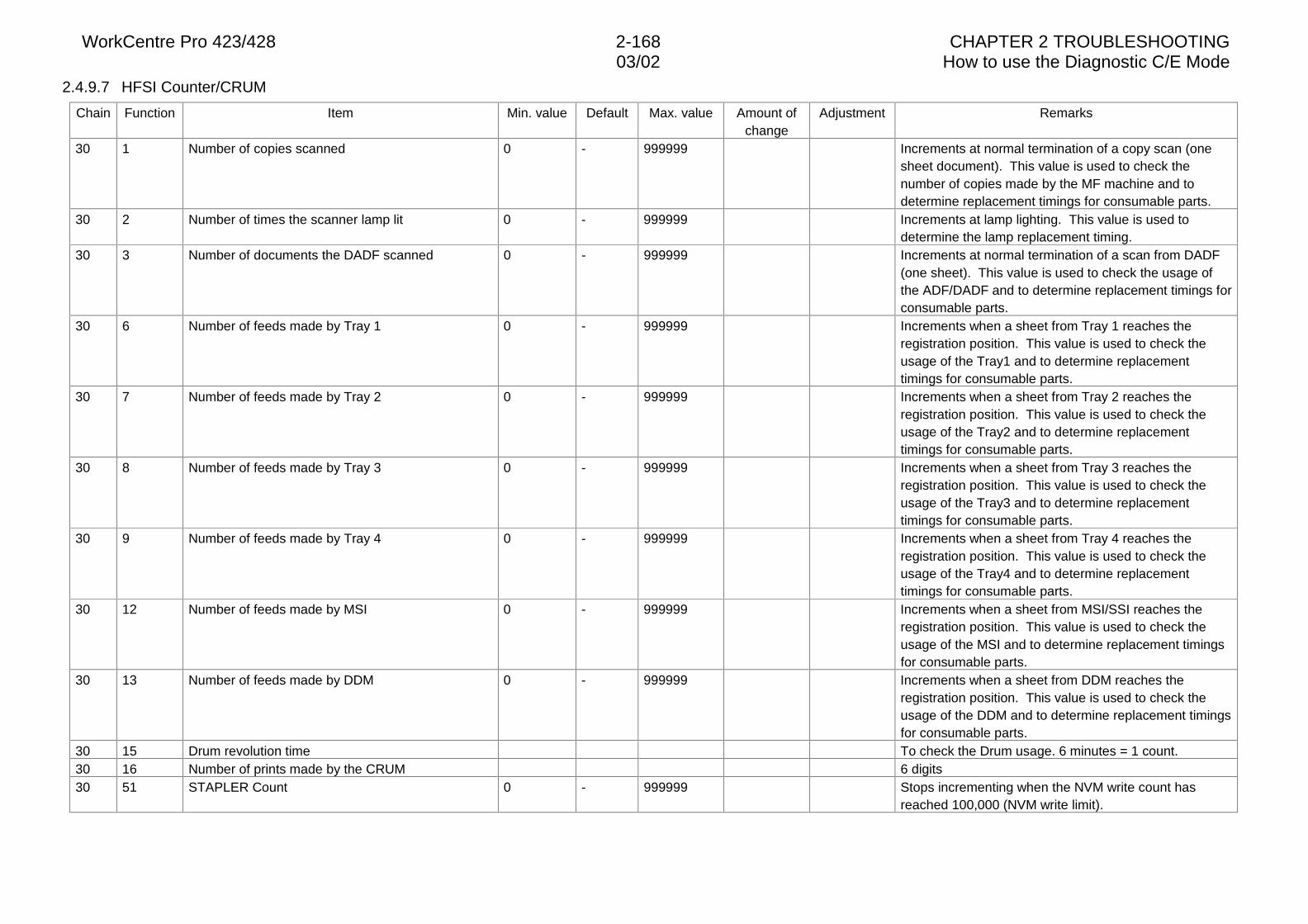
WorkCentre Pro 423/428 2-168 CHAPTER 2 TROUBLESHOOTING03/02 How to use the Diagnostic C/E Mode
2.4.9.7 HFSI Counter/CRUM
Chain Function Item Min. value Default Max. value Amount ofchange
Adjustment Remarks
30 1 Number of copies scanned 0 - 999999 Increments at normal termination of a copy scan (onesheet document). This value is used to check thenumber of copies made by the MF machine and todetermine replacement timings for consumable parts.
30 2 Number of times the scanner lamp lit 0 - 999999 Increments at lamp lighting. This value is used todetermine the lamp replacement timing.
30 3 Number of documents the DADF scanned 0 - 999999 Increments at normal termination of a scan from DADF(one sheet). This value is used to check the usage ofthe ADF/DADF and to determine replacement timings forconsumable parts.
30 6 Number of feeds made by Tray 1 0 - 999999 Increments when a sheet from Tray 1 reaches theregistration position. This value is used to check theusage of the Tray1 and to determine replacementtimings for consumable parts.
30 7 Number of feeds made by Tray 2 0 - 999999 Increments when a sheet from Tray 2 reaches theregistration position. This value is used to check theusage of the Tray2 and to determine replacementtimings for consumable parts.
30 8 Number of feeds made by Tray 3 0 - 999999 Increments when a sheet from Tray 3 reaches theregistration position. This value is used to check theusage of the Tray3 and to determine replacementtimings for consumable parts.
30 9 Number of feeds made by Tray 4 0 - 999999 Increments when a sheet from Tray 4 reaches theregistration position. This value is used to check theusage of the Tray4 and to determine replacementtimings for consumable parts.
30 12 Number of feeds made by MSI 0 - 999999 Increments when a sheet from MSI/SSI reaches theregistration position. This value is used to check theusage of the MSI and to determine replacement timingsfor consumable parts.
30 13 Number of feeds made by DDM 0 - 999999 Increments when a sheet from DDM reaches theregistration position. This value is used to check theusage of the DDM and to determine replacement timingsfor consumable parts.
30 15 Drum revolution time To check the Drum usage. 6 minutes = 1 count.30 16 Number of prints made by the CRUM 6 digits30 51 STAPLER Count 0 - 999999 Stops incrementing when the NVM write count has
reached 100,000 (NVM write limit).
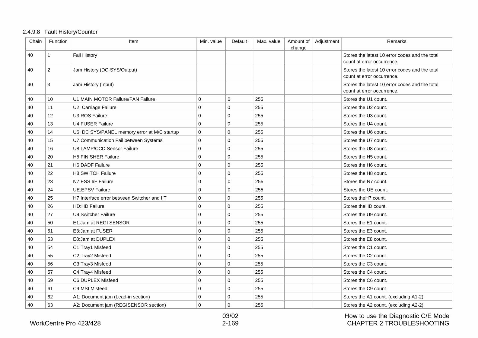
03/02 How to use the Diagnostic C/E ModeWorkCentre Pro 423/428 2-169 CHAPTER 2 TROUBLESHOOTING
2.4.9.8 Fault History/Counter
Chain Function Item Min. value Default Max. value Amount ofchange
Adjustment Remarks
40 1 Fail History Stores the latest 10 error codes and the totalcount at error occurrence.
40 2 Jam History (DC-SYS/Output) Stores the latest 10 error codes and the totalcount at error occurrence.
40 3 Jam History (Input) Stores the latest 10 error codes and the totalcount at error occurrence.
40 10 U1:MAIN MOTOR Failure/FAN Failure 0 0 255 Stores the U1 count.
40 11 U2: Carriage Failure 0 0 255 Stores the U2 count.
40 12 U3:ROS Failure 0 0 255 Stores the U3 count.
40 13 U4:FUSER Failure 0 0 255 Stores the U4 count.
40 14 U6: DC SYS/PANEL memory error at M/C startup 0 0 255 Stores the U6 count.
40 15 U7:Communication Fail between Systems 0 0 255 Stores the U7 count.
40 16 U8:LAMP/CCD Sensor Failure 0 0 255 Stores the U8 count.
40 20 H5:FINISHER Failure 0 0 255 Stores the H5 count.
40 21 H6:DADF Failure 0 0 255 Stores the H6 count.
40 22 H8:SWITCH Failure 0 0 255 Stores the H8 count.
40 23 N7:ESS I/F Failure 0 0 255 Stores the N7 count.
40 24 UE:EPSV Failure 0 0 255 Stores the UE count.
40 25 H7:Interface error between Switcher and IIT 0 0 255 Stores theH7 count.
40 26 HD:HD Failure 0 0 255 Stores theHD count.
40 27 U9:Switcher Failure 0 0 255 Stores the U9 count.
40 50 E1:Jam at REGI SENSOR 0 0 255 Stores the E1 count.
40 51 E3:Jam at FUSER 0 0 255 Stores the E3 count.
40 53 E8:Jam at DUPLEX 0 0 255 Stores the E8 count.
40 54 C1:Tray1 Misfeed 0 0 255 Stores the C1 count.
40 55 C2:Tray2 Misfeed 0 0 255 Stores the C2 count.
40 56 C3:Tray3 Misfeed 0 0 255 Stores the C3 count.
40 57 C4:Tray4 Misfeed 0 0 255 Stores the C4 count.
40 59 C6:DUPLEX Misfeed 0 0 255 Stores the C6 count.
40 61 C9:MSI Misfeed 0 0 255 Stores the C9 count.
40 62 A1: Document jam (Lead-in section) 0 0 255 Stores the A1 count. (excluding A1-2)
40 63 A2: Document jam (REGISENSOR section) 0 0 255 Stores the A2 count. (excluding A2-2)
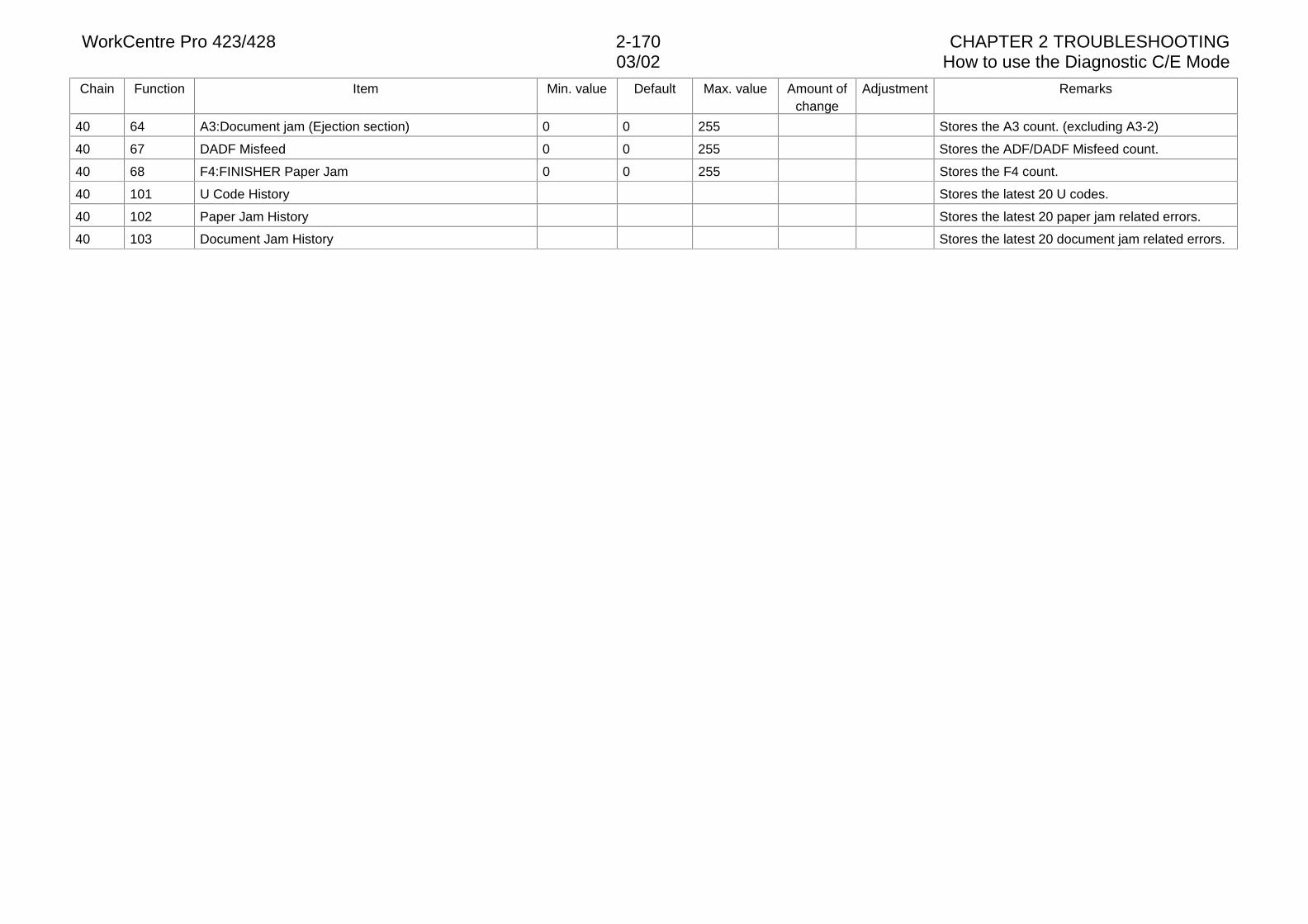
WorkCentre Pro 423/428 2-170 CHAPTER 2 TROUBLESHOOTING03/02 How to use the Diagnostic C/E Mode
Chain Function Item Min. value Default Max. value Amount ofchange
Adjustment Remarks
40 64 A3:Document jam (Ejection section) 0 0 255 Stores the A3 count. (excluding A3-2)
40 67 DADF Misfeed 0 0 255 Stores the ADF/DADF Misfeed count.
40 68 F4:FINISHER Paper Jam 0 0 255 Stores the F4 count.
40 101 U Code History Stores the latest 20 U codes.
40 102 Paper Jam History Stores the latest 20 paper jam related errors.
40 103 Document Jam History Stores the latest 20 document jam related errors.
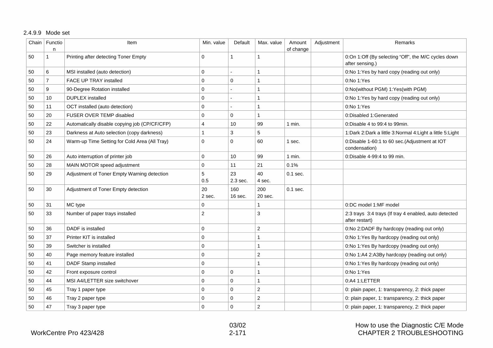
03/02 How to use the Diagnostic C/E ModeWorkCentre Pro 423/428 2-171 CHAPTER 2 TROUBLESHOOTING
2.4.9.9 Mode set
Chain Function
Item Min. value Default Max. value Amountof change
Adjustment Remarks
50 1 Printing after detecting Toner Empty 0 1 1 0:On 1:Off (By selecting “Off”, the M/C cycles downafter sensing.)
50 6 MSI installed (auto detection) 0 - 1 0:No 1:Yes by hard copy (reading out only)
50 7 FACE UP TRAY installed 0 0 1 0:No 1:Yes
50 9 90-Degree Rotation installed 0 - 1 0:No(without PGM) 1:Yes(with PGM)
50 10 DUPLEX installed 0 - 1 0:No 1:Yes by hard copy (reading out only)
50 11 OCT installed (auto detection) 0 - 1 0:No 1:Yes
50 20 FUSER OVER TEMP disabled 0 0 1 0:Disabled 1:Generated
50 22 Automatically disable copying job (CP/CF/CFP) 4 10 99 1 min. 0:Disable 4 to 99:4 to 99min.
50 23 Darkness at Auto selection (copy darkness) 1 3 5 1:Dark 2:Dark a little 3:Normal 4:Light a little 5:Light
50 24 Warm-up Time Setting for Cold Area (All Tray) 0 0 60 1 sec. 0:Disable 1-60:1 to 60 sec.(Adjustment at IOTcondensation)
50 26 Auto interruption of printer job 0 10 99 1 min. 0:Disable 4-99:4 to 99 min.
50 28 MAIN MOTOR speed adjustment 0 11 21 0.1%
50 29 Adjustment of Toner Empty Warning detection 50.5
232.3 sec.
404 sec.
0.1 sec.
50 30 Adjustment of Toner Empty detection 202 sec.
16016 sec.
20020 sec.
0.1 sec.
50 31 MC type 0 1 0:DC model 1:MF model
50 33 Number of paper trays installed 2 3 2:3 trays 3:4 trays (If tray 4 enabled, auto detectedafter restart)
50 36 DADF is installed 0 2 0:No 2:DADF By hardcopy (reading out only)
50 37 Printer KIT is installed 0 1 0:No 1:Yes By hardcopy (reading out only)
50 39 Switcher is installed 0 1 0:No 1:Yes By hardcopy (reading out only)
50 40 Page memory feature installed 0 2 0:No 1:A4 2:A3By hardcopy (reading out only)
50 41 DADF Stamp installed 0 1 0:No 1:Yes By hardcopy (reading out only)
50 42 Front exposure control 0 0 1 0:No 1:Yes
50 44 MSI A4/LETTER size switchover 0 0 1 0:A4 1:LETTER
50 45 Tray 1 paper type 0 0 2 0: plain paper, 1: transparency, 2: thick paper
50 46 Tray 2 paper type 0 0 2 0: plain paper, 1: transparency, 2: thick paper
50 47 Tray 3 paper type 0 0 2 0: plain paper, 1: transparency, 2: thick paper
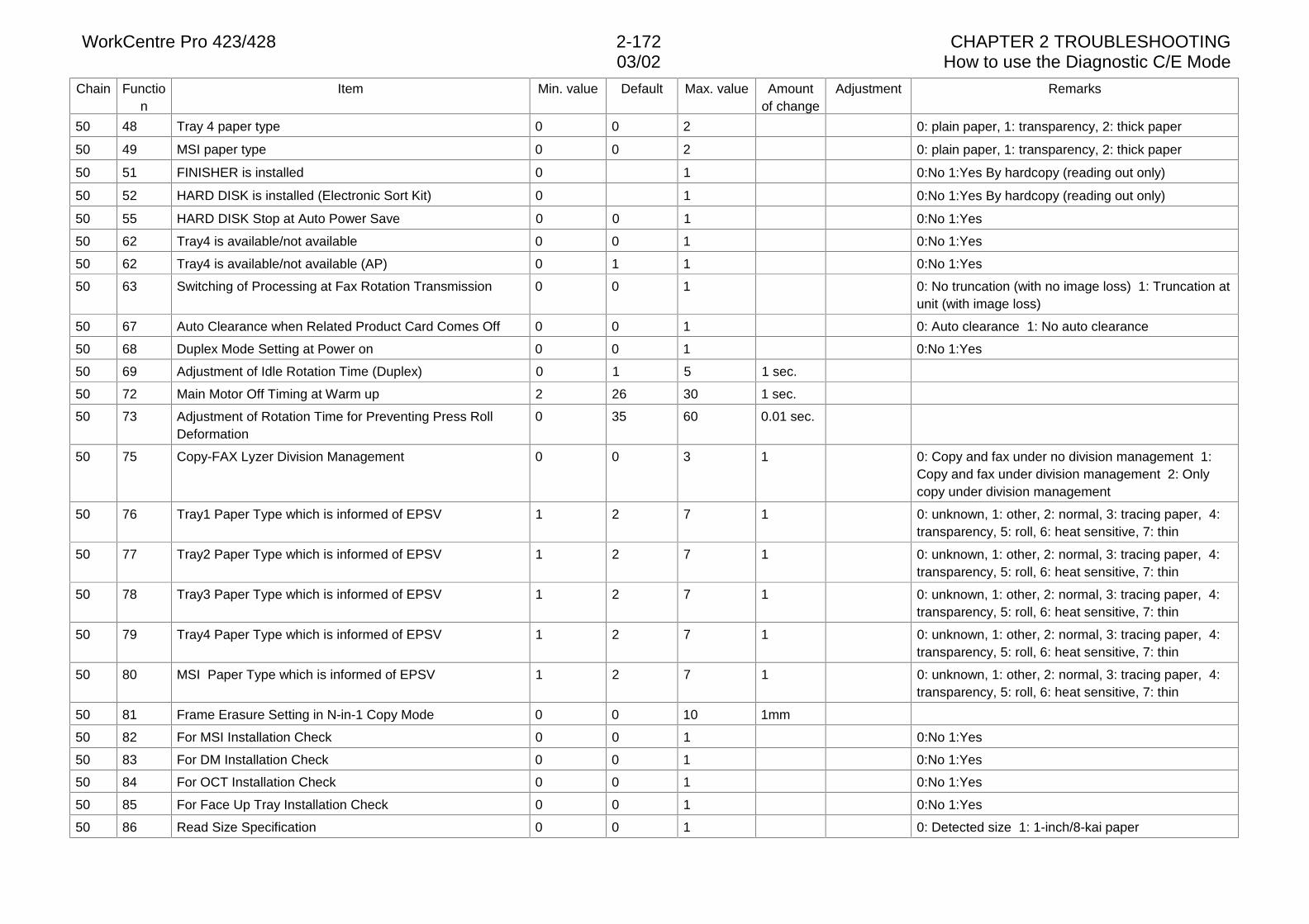
WorkCentre Pro 423/428 2-172 CHAPTER 2 TROUBLESHOOTING03/02 How to use the Diagnostic C/E Mode
Chain Function
Item Min. value Default Max. value Amountof change
Adjustment Remarks
50 48 Tray 4 paper type 0 0 2 0: plain paper, 1: transparency, 2: thick paper
50 49 MSI paper type 0 0 2 0: plain paper, 1: transparency, 2: thick paper
50 51 FINISHER is installed 0 1 0:No 1:Yes By hardcopy (reading out only)
50 52 HARD DISK is installed (Electronic Sort Kit) 0 1 0:No 1:Yes By hardcopy (reading out only)
50 55 HARD DISK Stop at Auto Power Save 0 0 1 0:No 1:Yes
50 62 Tray4 is available/not available 0 0 1 0:No 1:Yes
50 62 Tray4 is available/not available (AP) 0 1 1 0:No 1:Yes
50 63 Switching of Processing at Fax Rotation Transmission 0 0 1 0: No truncation (with no image loss) 1: Truncation atunit (with image loss)
50 67 Auto Clearance when Related Product Card Comes Off 0 0 1 0: Auto clearance 1: No auto clearance
50 68 Duplex Mode Setting at Power on 0 0 1 0:No 1:Yes
50 69 Adjustment of Idle Rotation Time (Duplex) 0 1 5 1 sec.
50 72 Main Motor Off Timing at Warm up 2 26 30 1 sec.
50 73 Adjustment of Rotation Time for Preventing Press RollDeformation
0 35 60 0.01 sec.
50 75 Copy-FAX Lyzer Division Management 0 0 3 1 0: Copy and fax under no division management 1:Copy and fax under division management 2: Onlycopy under division management
50 76 Tray1 Paper Type which is informed of EPSV 1 2 7 1 0: unknown, 1: other, 2: normal, 3: tracing paper, 4:transparency, 5: roll, 6: heat sensitive, 7: thin
50 77 Tray2 Paper Type which is informed of EPSV 1 2 7 1 0: unknown, 1: other, 2: normal, 3: tracing paper, 4:transparency, 5: roll, 6: heat sensitive, 7: thin
50 78 Tray3 Paper Type which is informed of EPSV 1 2 7 1 0: unknown, 1: other, 2: normal, 3: tracing paper, 4:transparency, 5: roll, 6: heat sensitive, 7: thin
50 79 Tray4 Paper Type which is informed of EPSV 1 2 7 1 0: unknown, 1: other, 2: normal, 3: tracing paper, 4:transparency, 5: roll, 6: heat sensitive, 7: thin
50 80 MSI Paper Type which is informed of EPSV 1 2 7 1 0: unknown, 1: other, 2: normal, 3: tracing paper, 4:transparency, 5: roll, 6: heat sensitive, 7: thin
50 81 Frame Erasure Setting in N-in-1 Copy Mode 0 0 10 1mm
50 82 For MSI Installation Check 0 0 1 0:No 1:Yes
50 83 For DM Installation Check 0 0 1 0:No 1:Yes
50 84 For OCT Installation Check 0 0 1 0:No 1:Yes
50 85 For Face Up Tray Installation Check 0 0 1 0:No 1:Yes
50 86 Read Size Specification 0 0 1 0: Detected size 1: 1-inch/8-kai paper
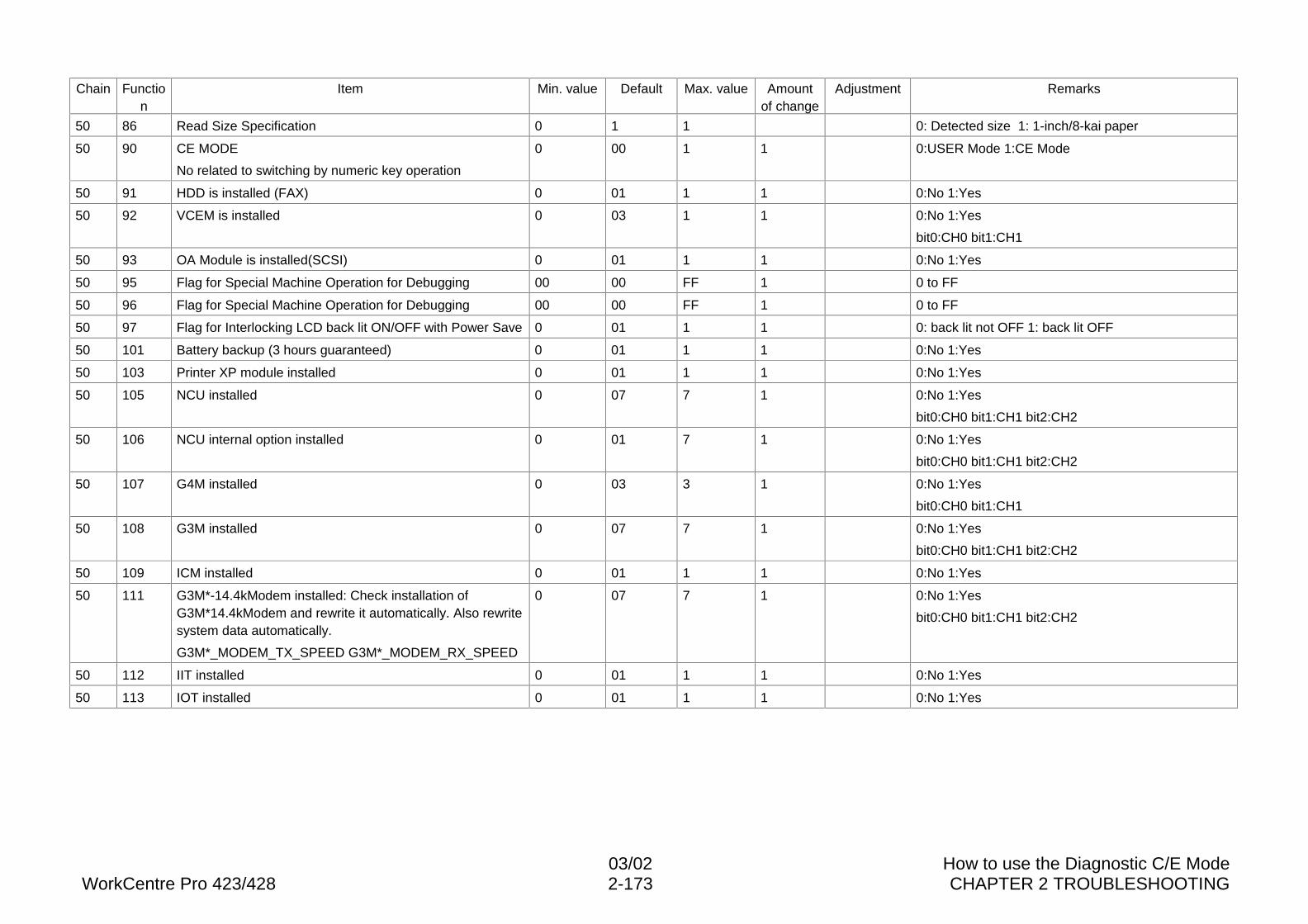
03/02 How to use the Diagnostic C/E ModeWorkCentre Pro 423/428 2-173 CHAPTER 2 TROUBLESHOOTING
Chain Function
Item Min. value Default Max. value Amountof change
Adjustment Remarks
50 86 Read Size Specification 0 1 1 0: Detected size 1: 1-inch/8-kai paper
50 90 CE MODE
No related to switching by numeric key operation
0 00 1 1 0:USER Mode 1:CE Mode
50 91 HDD is installed (FAX) 0 01 1 1 0:No 1:Yes
50 92 VCEM is installed 0 03 1 1 0:No 1:Yes
bit0:CH0 bit1:CH1
50 93 OA Module is installed(SCSI) 0 01 1 1 0:No 1:Yes
50 95 Flag for Special Machine Operation for Debugging 00 00 FF 1 0 to FF
50 96 Flag for Special Machine Operation for Debugging 00 00 FF 1 0 to FF
50 97 Flag for Interlocking LCD back lit ON/OFF with Power Save 0 01 1 1 0: back lit not OFF 1: back lit OFF
50 101 Battery backup (3 hours guaranteed) 0 01 1 1 0:No 1:Yes
50 103 Printer XP module installed 0 01 1 1 0:No 1:Yes
50 105 NCU installed 0 07 7 1 0:No 1:Yes
bit0:CH0 bit1:CH1 bit2:CH2
50 106 NCU internal option installed 0 01 7 1 0:No 1:Yes
bit0:CH0 bit1:CH1 bit2:CH2
50 107 G4M installed 0 03 3 1 0:No 1:Yes
bit0:CH0 bit1:CH1
50 108 G3M installed 0 07 7 1 0:No 1:Yes
bit0:CH0 bit1:CH1 bit2:CH2
50 109 ICM installed 0 01 1 1 0:No 1:Yes
50 111 G3M*-14.4kModem installed: Check installation ofG3M*14.4kModem and rewrite it automatically. Also rewritesystem data automatically.
G3M*_MODEM_TX_SPEED G3M*_MODEM_RX_SPEED
0 07 7 1 0:No 1:Yes
bit0:CH0 bit1:CH1 bit2:CH2
50 112 IIT installed 0 01 1 1 0:No 1:Yes
50 113 IOT installed 0 01 1 1 0:No 1:Yes
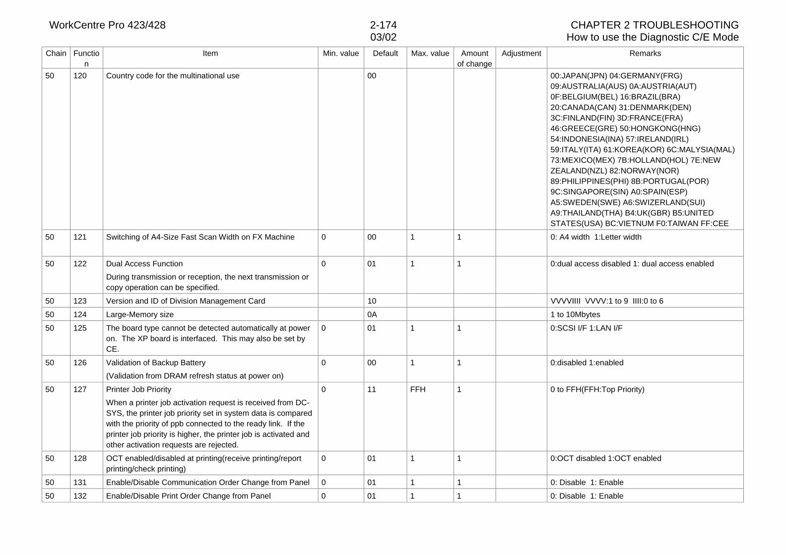
WorkCentre Pro 423/428 2-174 CHAPTER 2 TROUBLESHOOTING03/02 How to use the Diagnostic C/E Mode
Chain Function
Item Min. value Default Max. value Amountof change
Adjustment Remarks
50 120 Country code for the multinational use 00 00:JAPAN(JPN) 04:GERMANY(FRG)09:AUSTRALIA(AUS) 0A:AUSTRIA(AUT)0F:BELGIUM(BEL) 16:BRAZIL(BRA)20:CANADA(CAN) 31:DENMARK(DEN)3C:FINLAND(FIN) 3D:FRANCE(FRA)46:GREECE(GRE) 50:HONGKONG(HNG)54:INDONESIA(INA) 57:IRELAND(IRL)59:ITALY(ITA) 61:KOREA(KOR) 6C:MALYSIA(MAL)73:MEXICO(MEX) 7B:HOLLAND(HOL) 7E:NEWZEALAND(NZL) 82:NORWAY(NOR)89:PHILIPPINES(PHI) 8B:PORTUGAL(POR)9C:SINGAPORE(SIN) A0:SPAIN(ESP)A5:SWEDEN(SWE) A6:SWIZERLAND(SUI)A9:THAILAND(THA) B4:UK(GBR) B5:UNITEDSTATES(USA) BC:VIETNUM F0:TAIWAN FF:CEE
50 121 Switching of A4-Size Fast Scan Width on FX Machine 0 00 1 1 0: A4 width 1:Letter width
50 122 Dual Access Function
During transmission or reception, the next transmission orcopy operation can be specified.
0 01 1 1 0:dual access disabled 1: dual access enabled
50 123 Version and ID of Division Management Card 10 VVVVIIII VVVV:1 to 9 IIII:0 to 6
50 124 Large-Memory size 0A 1 to 10Mbytes
50 125 The board type cannot be detected automatically at poweron. The XP board is interfaced. This may also be set byCE.
0 01 1 1 0:SCSI I/F 1:LAN I/F
50 126 Validation of Backup Battery
(Validation from DRAM refresh status at power on)
0 00 1 1 0:disabled 1:enabled
50 127 Printer Job Priority
When a printer job activation request is received from DC-SYS, the printer job priority set in system data is comparedwith the priority of ppb connected to the ready link. If theprinter job priority is higher, the printer job is activated andother activation requests are rejected.
0 11 FFH 1 0 to FFH(FFH:Top Priority)
50 128 OCT enabled/disabled at printing(receive printing/reportprinting/check printing)
0 01 1 1 0:OCT disabled 1:OCT enabled
50 131 Enable/Disable Communication Order Change from Panel 0 01 1 1 0: Disable 1: Enable
50 132 Enable/Disable Print Order Change from Panel 0 01 1 1 0: Disable 1: Enable
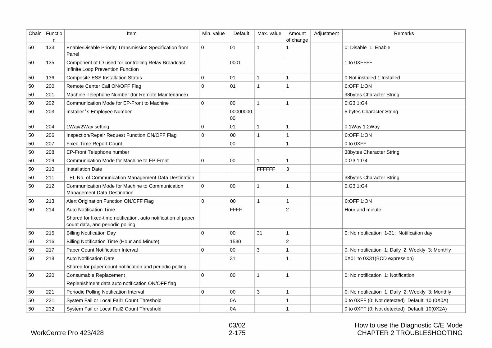
03/02 How to use the Diagnostic C/E ModeWorkCentre Pro 423/428 2-175 CHAPTER 2 TROUBLESHOOTING
Chain Function
Item Min. value Default Max. value Amountof change
Adjustment Remarks
50 133 Enable/Disable Priority Transmission Specification fromPanel
0 01 1 1 0: Disable 1: Enable
50 135 Component of ID used for controlling Relay BroadcastInfinite Loop Prevention Function
0001 1 to 0XFFFF
50 136 Composite ESS Installation Status 0 01 1 1 0:Not installed 1:Installed
50 200 Remote Center Call ON/OFF Flag 0 01 1 1 0:OFF 1:ON
50 201 Machine Telephone Number (for Remote Maintenance) 38bytes Character String
50 202 Communication Mode for EP-Front to Machine 0 00 1 1 0:G3 1:G4
50 203 Installer·s Employee Number 0000000000
5 bytes Character String
50 204 1Way/2Way setting 0 01 1 1 0:1Way 1:2Way
50 206 Inspection/Repair Request Function ON/OFF Flag 0 00 1 1 0:OFF 1:ON
50 207 Fixed-Time Report Count 00 1 0 to 0XFF
50 208 EP-Front Telephone number 38bytes Character String
50 209 Communication Mode for Machine to EP-Front 0 00 1 1 0:G3 1:G4
50 210 Installation Date FFFFFF 3
50 211 TEL No. of Communication Management Data Destination 38bytes Character String
50 212 Communication Mode for Machine to CommunicationManagement Data Destination
0 00 1 1 0:G3 1:G4
50 213 Alert Origination Function ON/OFF Flag 0 00 1 1 0:OFF 1:ON
50 214 Auto Notification Time
Shared for fixed-time notification, auto notification of papercount data, and periodic polling.
FFFF 2 Hour and minute
50 215 Billing Notification Day 0 00 31 1 0: No notification 1-31: Notification day
50 216 Billing Notification Time (Hour and Minute) 1530 2
50 217 Paper Count Notification Interval 0 00 3 1 0: No notification 1: Daily 2: Weekly 3: Monthly
50 218 Auto Notification Date
Shared for paper count notification and periodic polling.
31 1 0X01 to 0X31(BCD expression)
50 220 Consumable Replacement
Replenishment data auto notification ON/OFF flag
0 00 1 1 0: No notification 1: Notification
50 221 Periodic Polling Notification Interval 0 00 3 1 0: No notification 1: Daily 2: Weekly 3: Monthly
50 231 System Fail or Local Fail1 Count Threshold 0A 1 0 to 0XFF (0: Not detected) Default: 10 (0X0A)
50 232 System Fail or Local Fail2 Count Threshold 0A 1 0 to 0XFF (0: Not detected) Default: 10(0X2A)
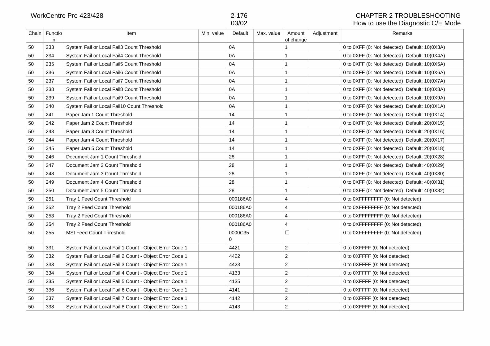
WorkCentre Pro 423/428 2-176 CHAPTER 2 TROUBLESHOOTING03/02 How to use the Diagnostic C/E Mode
Chain Function
Item Min. value Default Max. value Amountof change
Adjustment Remarks
50 233 System Fail or Local Fail3 Count Threshold 0A 1 0 to 0XFF (0: Not detected) Default: 10(0X3A)
50 234 System Fail or Local Fail4 Count Threshold 0A 1 0 to 0XFF (0: Not detected) Default: 10(0X4A)
50 235 System Fail or Local Fail5 Count Threshold 0A 1 0 to 0XFF (0: Not detected) Default: 10(0X5A)
50 236 System Fail or Local Fail6 Count Threshold 0A 1 0 to 0XFF (0: Not detected) Default: 10(0X6A)
50 237 System Fail or Local Fail7 Count Threshold 0A 1 0 to 0XFF (0: Not detected) Default: 10(0X7A)
50 238 System Fail or Local Fail8 Count Threshold 0A 1 0 to 0XFF (0: Not detected) Default: 10(0X8A)
50 239 System Fail or Local Fail9 Count Threshold 0A 1 0 to 0XFF (0: Not detected) Default: 10(0X9A)
50 240 System Fail or Local Fail10 Count Threshold 0A 1 0 to 0XFF (0: Not detected) Default: 10(0X1A)
50 241 Paper Jam 1 Count Threshold 14 1 0 to 0XFF (0: Not detected) Default: 10(0X14)
50 242 Paper Jam 2 Count Threshold 14 1 0 to 0XFF (0: Not detected) Default: 20(0X15)
50 243 Paper Jam 3 Count Threshold 14 1 0 to 0XFF (0: Not detected) Default: 20(0X16)
50 244 Paper Jam 4 Count Threshold 14 1 0 to 0XFF (0: Not detected) Default: 20(0X17)
50 245 Paper Jam 5 Count Threshold 14 1 0 to 0XFF (0: Not detected) Default: 20(0X18)
50 246 Document Jam 1 Count Threshold 28 1 0 to 0XFF (0: Not detected) Default: 20(0X28)
50 247 Document Jam 2 Count Threshold 28 1 0 to 0XFF (0: Not detected) Default: 40(0X29)
50 248 Document Jam 3 Count Threshold 28 1 0 to 0XFF (0: Not detected) Default: 40(0X30)
50 249 Document Jam 4 Count Threshold 28 1 0 to 0XFF (0: Not detected) Default: 40(0X31)
50 250 Document Jam 5 Count Threshold 28 1 0 to 0XFF (0: Not detected) Default: 40(0X32)
50 251 Tray 1 Feed Count Threshold 000186A0 4 0 to 0XFFFFFFFF (0: Not detected)
50 252 Tray 2 Feed Count Threshold 000186A0 4 0 to 0XFFFFFFFF (0: Not detected)
50 253 Tray 2 Feed Count Threshold 000186A0 4 0 to 0XFFFFFFFF (0: Not detected)
50 254 Tray 2 Feed Count Threshold 000186A0 4 0 to 0XFFFFFFFF (0: Not detected)
50 255 MSI Feed Count Threshold 0000C350
� 0 to 0XFFFFFFFF (0: Not detected)
50 331 System Fail or Local Fail 1 Count - Object Error Code 1 4421 2 0 to 0XFFFF (0: Not detected)
50 332 System Fail or Local Fail 2 Count - Object Error Code 1 4422 2 0 to 0XFFFF (0: Not detected)
50 333 System Fail or Local Fail 3 Count - Object Error Code 1 4423 2 0 to 0XFFFF (0: Not detected)
50 334 System Fail or Local Fail 4 Count - Object Error Code 1 4133 2 0 to 0XFFFF (0: Not detected)
50 335 System Fail or Local Fail 5 Count - Object Error Code 1 4135 2 0 to 0XFFFF (0: Not detected)
50 336 System Fail or Local Fail 6 Count - Object Error Code 1 4141 2 0 to 0XFFFF (0: Not detected)
50 337 System Fail or Local Fail 7 Count - Object Error Code 1 4142 2 0 to 0XFFFF (0: Not detected)
50 338 System Fail or Local Fail 8 Count - Object Error Code 1 4143 2 0 to 0XFFFF (0: Not detected)
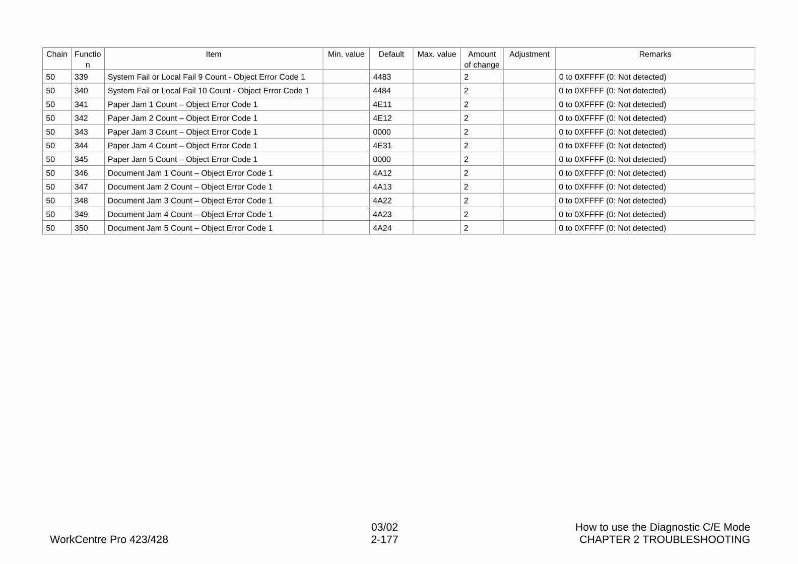
03/02 How to use the Diagnostic C/E ModeWorkCentre Pro 423/428 2-177 CHAPTER 2 TROUBLESHOOTING
Chain Function
Item Min. value Default Max. value Amountof change
Adjustment Remarks
50 339 System Fail or Local Fail 9 Count - Object Error Code 1 4483 2 0 to 0XFFFF (0: Not detected)
50 340 System Fail or Local Fail 10 Count - Object Error Code 1 4484 2 0 to 0XFFFF (0: Not detected)
50 341 Paper Jam 1 Count – Object Error Code 1 4E11 2 0 to 0XFFFF (0: Not detected)
50 342 Paper Jam 2 Count – Object Error Code 1 4E12 2 0 to 0XFFFF (0: Not detected)
50 343 Paper Jam 3 Count – Object Error Code 1 0000 2 0 to 0XFFFF (0: Not detected)
50 344 Paper Jam 4 Count – Object Error Code 1 4E31 2 0 to 0XFFFF (0: Not detected)
50 345 Paper Jam 5 Count – Object Error Code 1 0000 2 0 to 0XFFFF (0: Not detected)
50 346 Document Jam 1 Count – Object Error Code 1 4A12 2 0 to 0XFFFF (0: Not detected)
50 347 Document Jam 2 Count – Object Error Code 1 4A13 2 0 to 0XFFFF (0: Not detected)
50 348 Document Jam 3 Count – Object Error Code 1 4A22 2 0 to 0XFFFF (0: Not detected)
50 349 Document Jam 4 Count – Object Error Code 1 4A23 2 0 to 0XFFFF (0: Not detected)
50 350 Document Jam 5 Count – Object Error Code 1 4A24 2 0 to 0XFFFF (0: Not detected)
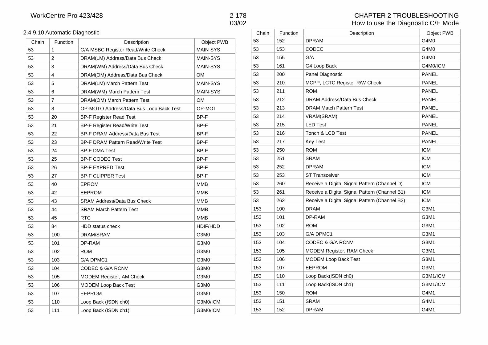
WorkCentre Pro 423/428 2-178 CHAPTER 2 TROUBLESHOOTING03/02 How to use the Diagnostic C/E Mode
2.4.9.10 Automatic Diagnostic
Chain Function Description Object PWB
53 1 G/A MSBC Register Read/Write Check MAIN-SYS
53 2 DRAM(LM) Address/Data Bus Check MAIN-SYS
53 3 DRAM(WM) Address/Data Bus Check MAIN-SYS
53 4 DRAM(OM) Address/Data Bus Check OM
53 5 DRAM(LM) March Pattern Test MAIN-SYS
53 6 DRAM(WM) March Pattern Test MAIN-SYS
53 7 DRAM(OM) March Pattern Test OM
53 8 OP-MOTO Address/Data Bus Loop Back Test OP-MOT
53 20 BP-F Register Read Test BP-F
53 21 BP-F Register Read/Write Test BP-F
53 22 BP-F DRAM Address/Data Bus Test BP-F
53 23 BP-F DRAM Pattern Read/Write Test BP-F
53 24 BP-F DMA Test BP-F
53 25 BP-F CODEC Test BP-F
53 26 BP-F EXPRED Test BP-F
53 27 BP-F CLIPPER Test BP-F
53 40 EPROM MMB
53 42 EEPROM MMB
53 43 SRAM Address/Data Bus Check MMB
53 44 SRAM March Pattern Test MMB
53 45 RTC MMB
53 84 HDD status check HDIF/HDD
53 100 DRAM/SRAM G3M0
53 101 DP-RAM G3M0
53 102 ROM G3M0
53 103 G/A DPMC1 G3M0
53 104 CODEC & G/A RCNV G3M0
53 105 MODEM Register, AM Check G3M0
53 106 MODEM Loop Back Test G3M0
53 107 EEPROM G3M0
53 110 Loop Back (ISDN ch0) G3M0/ICM
53 111 Loop Back (ISDN ch1) G3M0/ICM
Chain Function Description Object PWB
53 152 DPRAM G4M0
53 153 CODEC G4M0
53 155 G/A G4M0
53 161 G4 Loop Back G4M0/ICM
53 200 Panel Diagnostic PANEL
53 210 MCPP, LCTC Register R/W Check PANEL
53 211 ROM PANEL
53 212 DRAM Address/Data Bus Check PANEL
53 213 DRAM Match Pattern Test PANEL
53 214 VRAM(SRAM) PANEL
53 215 LED Test PANEL
53 216 Tonch & LCD Test PANEL
53 217 Key Test PANEL
53 250 ROM ICM
53 251 SRAM ICM
53 252 DPRAM ICM
53 253 ST Transceiver ICM
53 260 Receive a Digital Signal Pattern (Channel D) ICM
53 261 Receive a Digital Signal Pattern (Channel B1) ICM
53 262 Receive a Digital Signal Pattern (Channel B2) ICM
153 100 DRAM G3M1
153 101 DP-RAM G3M1
153 102 ROM G3M1
153 103 G/A DPMC1 G3M1
153 104 CODEC & G/A RCNV G3M1
153 105 MODEM Register, RAM Check G3M1
153 106 MODEM Loop Back Test G3M1
153 107 EEPROM G3M1
153 110 Loop Back(ISDN ch0) G3M1/ICM
153 111 Loop Back(ISDN ch1) G3M1/ICM
153 150 ROM G4M1
153 151 SRAM G4M1
153 152 DPRAM G4M1
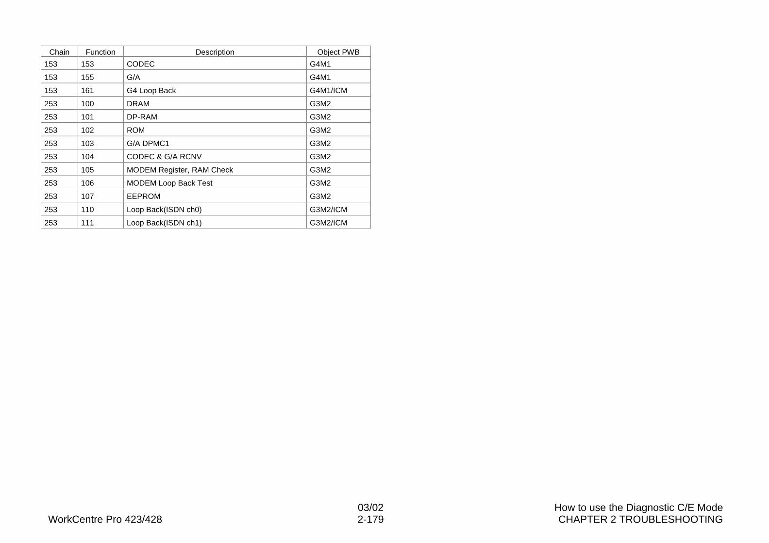
03/02 How to use the Diagnostic C/E ModeWorkCentre Pro 423/428 2-179 CHAPTER 2 TROUBLESHOOTING
Chain Function Description Object PWB
153 153 CODEC G4M1
153 155 G/A G4M1
153 161 G4 Loop Back G4M1/ICM
253 100 DRAM G3M2
253 101 DP-RAM G3M2
253 102 ROM G3M2
253 103 G/A DPMC1 G3M2
253 104 CODEC & G/A RCNV G3M2
253 105 MODEM Register, RAM Check G3M2
253 106 MODEM Loop Back Test G3M2
253 107 EEPROM G3M2
253 110 Loop Back(ISDN ch0) G3M2/ICM
253 111 Loop Back(ISDN ch1) G3M2/ICM
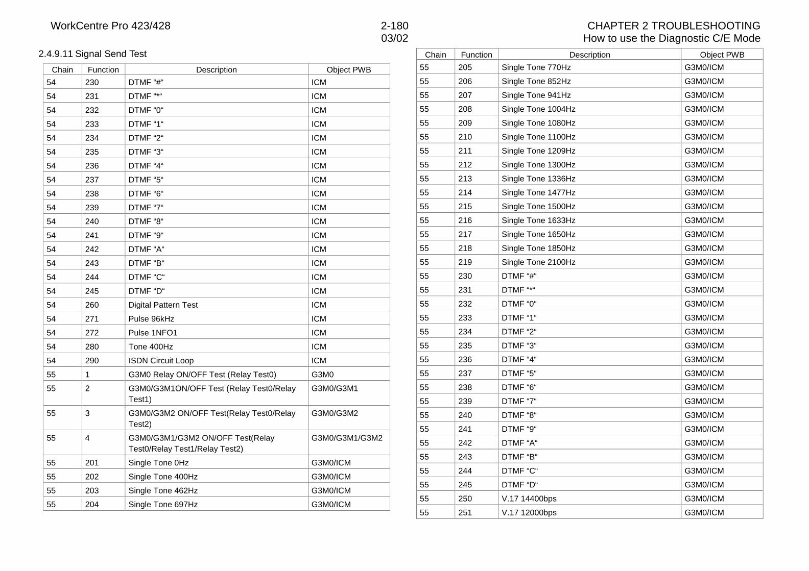
WorkCentre Pro 423/428 2-180 CHAPTER 2 TROUBLESHOOTING03/02 How to use the Diagnostic C/E Mode
2.4.9.11 Signal Send Test
Chain Function Description Object PWB
54 230 DTMF “#“ ICM
54 231 DTMF “*“ ICM
54 232 DTMF “0“ ICM
54 233 DTMF “1“ ICM
54 234 DTMF “2“ ICM
54 235 DTMF “3“ ICM
54 236 DTMF “4“ ICM
54 237 DTMF “5“ ICM
54 238 DTMF “6“ ICM
54 239 DTMF “7“ ICM
54 240 DTMF “8“ ICM
54 241 DTMF “9“ ICM
54 242 DTMF “A“ ICM
54 243 DTMF “B“ ICM
54 244 DTMF “C“ ICM
54 245 DTMF “D“ ICM
54 260 Digital Pattern Test ICM
54 271 Pulse 96kHz ICM
54 272 Pulse 1NFO1 ICM
54 280 Tone 400Hz ICM
54 290 ISDN Circuit Loop ICM
55 1 G3M0 Relay ON/OFF Test (Relay Test0) G3M0
55 2 G3M0/G3M1ON/OFF Test (Relay Test0/RelayTest1)
G3M0/G3M1
55 3 G3M0/G3M2 ON/OFF Test(Relay Test0/RelayTest2)
G3M0/G3M2
55 4 G3M0/G3M1/G3M2 ON/OFF Test(RelayTest0/Relay Test1/Relay Test2)
G3M0/G3M1/G3M2
55 201 Single Tone 0Hz G3M0/ICM
55 202 Single Tone 400Hz G3M0/ICM
55 203 Single Tone 462Hz G3M0/ICM
55 204 Single Tone 697Hz G3M0/ICM
Chain Function Description Object PWB
55 205 Single Tone 770Hz G3M0/ICM
55 206 Single Tone 852Hz G3M0/ICM
55 207 Single Tone 941Hz G3M0/ICM
55 208 Single Tone 1004Hz G3M0/ICM
55 209 Single Tone 1080Hz G3M0/ICM
55 210 Single Tone 1100Hz G3M0/ICM
55 211 Single Tone 1209Hz G3M0/ICM
55 212 Single Tone 1300Hz G3M0/ICM
55 213 Single Tone 1336Hz G3M0/ICM
55 214 Single Tone 1477Hz G3M0/ICM
55 215 Single Tone 1500Hz G3M0/ICM
55 216 Single Tone 1633Hz G3M0/ICM
55 217 Single Tone 1650Hz G3M0/ICM
55 218 Single Tone 1850Hz G3M0/ICM
55 219 Single Tone 2100Hz G3M0/ICM
55 230 DTMF “#“ G3M0/ICM
55 231 DTMF “*“ G3M0/ICM
55 232 DTMF “0“ G3M0/ICM
55 233 DTMF “1“ G3M0/ICM
55 234 DTMF “2“ G3M0/ICM
55 235 DTMF “3“ G3M0/ICM
55 236 DTMF “4“ G3M0/ICM
55 237 DTMF “5“ G3M0/ICM
55 238 DTMF “6“ G3M0/ICM
55 239 DTMF “7“ G3M0/ICM
55 240 DTMF “8“ G3M0/ICM
55 241 DTMF “9“ G3M0/ICM
55 242 DTMF “A“ G3M0/ICM
55 243 DTMF “B“ G3M0/ICM
55 244 DTMF “C“ G3M0/ICM
55 245 DTMF “D“ G3M0/ICM
55 250 V.17 14400bps G3M0/ICM
55 251 V.17 12000bps G3M0/ICM
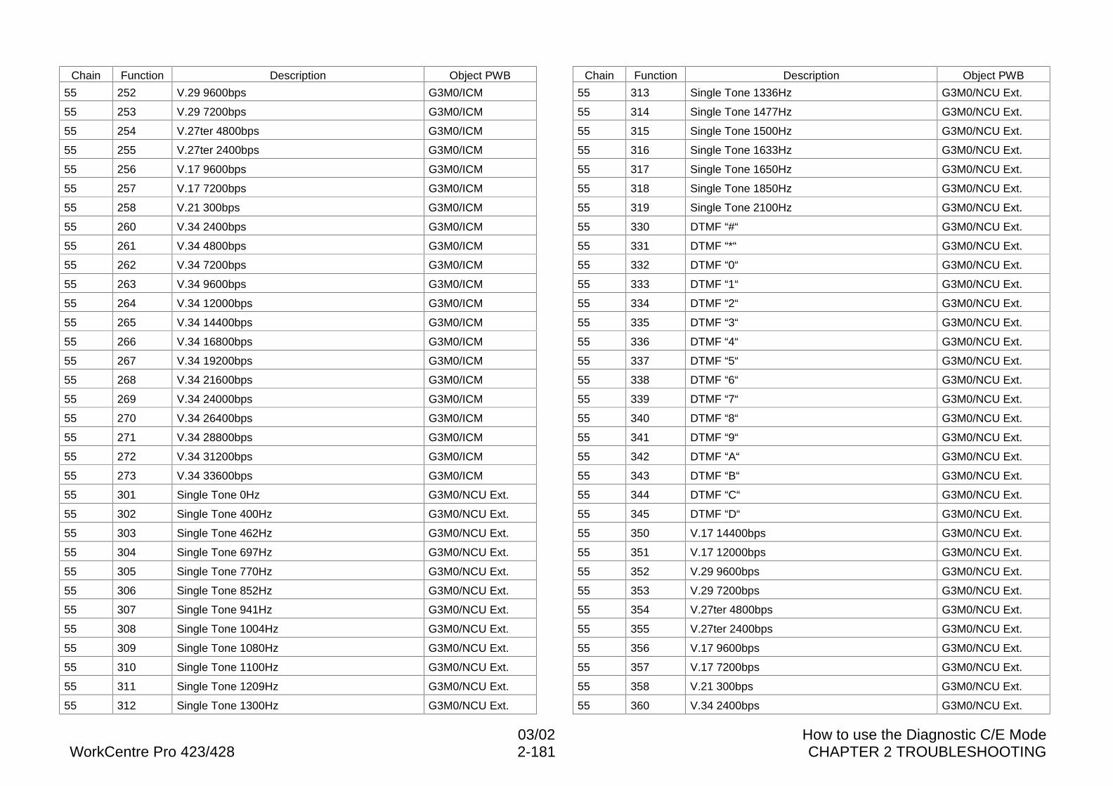
03/02 How to use the Diagnostic C/E ModeWorkCentre Pro 423/428 2-181 CHAPTER 2 TROUBLESHOOTING
Chain Function Description Object PWB
55 252 V.29 9600bps G3M0/ICM
55 253 V.29 7200bps G3M0/ICM
55 254 V.27ter 4800bps G3M0/ICM
55 255 V.27ter 2400bps G3M0/ICM
55 256 V.17 9600bps G3M0/ICM
55 257 V.17 7200bps G3M0/ICM
55 258 V.21 300bps G3M0/ICM
55 260 V.34 2400bps G3M0/ICM
55 261 V.34 4800bps G3M0/ICM
55 262 V.34 7200bps G3M0/ICM
55 263 V.34 9600bps G3M0/ICM
55 264 V.34 12000bps G3M0/ICM
55 265 V.34 14400bps G3M0/ICM
55 266 V.34 16800bps G3M0/ICM
55 267 V.34 19200bps G3M0/ICM
55 268 V.34 21600bps G3M0/ICM
55 269 V.34 24000bps G3M0/ICM
55 270 V.34 26400bps G3M0/ICM
55 271 V.34 28800bps G3M0/ICM
55 272 V.34 31200bps G3M0/ICM
55 273 V.34 33600bps G3M0/ICM
55 301 Single Tone 0Hz G3M0/NCU Ext.
55 302 Single Tone 400Hz G3M0/NCU Ext.
55 303 Single Tone 462Hz G3M0/NCU Ext.
55 304 Single Tone 697Hz G3M0/NCU Ext.
55 305 Single Tone 770Hz G3M0/NCU Ext.
55 306 Single Tone 852Hz G3M0/NCU Ext.
55 307 Single Tone 941Hz G3M0/NCU Ext.
55 308 Single Tone 1004Hz G3M0/NCU Ext.
55 309 Single Tone 1080Hz G3M0/NCU Ext.
55 310 Single Tone 1100Hz G3M0/NCU Ext.
55 311 Single Tone 1209Hz G3M0/NCU Ext.
55 312 Single Tone 1300Hz G3M0/NCU Ext.
Chain Function Description Object PWB
55 313 Single Tone 1336Hz G3M0/NCU Ext.
55 314 Single Tone 1477Hz G3M0/NCU Ext.
55 315 Single Tone 1500Hz G3M0/NCU Ext.
55 316 Single Tone 1633Hz G3M0/NCU Ext.
55 317 Single Tone 1650Hz G3M0/NCU Ext.
55 318 Single Tone 1850Hz G3M0/NCU Ext.
55 319 Single Tone 2100Hz G3M0/NCU Ext.
55 330 DTMF “#“ G3M0/NCU Ext.
55 331 DTMF “*“ G3M0/NCU Ext.
55 332 DTMF “0“ G3M0/NCU Ext.
55 333 DTMF “1“ G3M0/NCU Ext.
55 334 DTMF “2“ G3M0/NCU Ext.
55 335 DTMF “3“ G3M0/NCU Ext.
55 336 DTMF “4“ G3M0/NCU Ext.
55 337 DTMF “5“ G3M0/NCU Ext.
55 338 DTMF “6“ G3M0/NCU Ext.
55 339 DTMF “7“ G3M0/NCU Ext.
55 340 DTMF “8“ G3M0/NCU Ext.
55 341 DTMF “9“ G3M0/NCU Ext.
55 342 DTMF “A“ G3M0/NCU Ext.
55 343 DTMF “B“ G3M0/NCU Ext.
55 344 DTMF “C“ G3M0/NCU Ext.
55 345 DTMF “D“ G3M0/NCU Ext.
55 350 V.17 14400bps G3M0/NCU Ext.
55 351 V.17 12000bps G3M0/NCU Ext.
55 352 V.29 9600bps G3M0/NCU Ext.
55 353 V.29 7200bps G3M0/NCU Ext.
55 354 V.27ter 4800bps G3M0/NCU Ext.
55 355 V.27ter 2400bps G3M0/NCU Ext.
55 356 V.17 9600bps G3M0/NCU Ext.
55 357 V.17 7200bps G3M0/NCU Ext.
55 358 V.21 300bps G3M0/NCU Ext.
55 360 V.34 2400bps G3M0/NCU Ext.
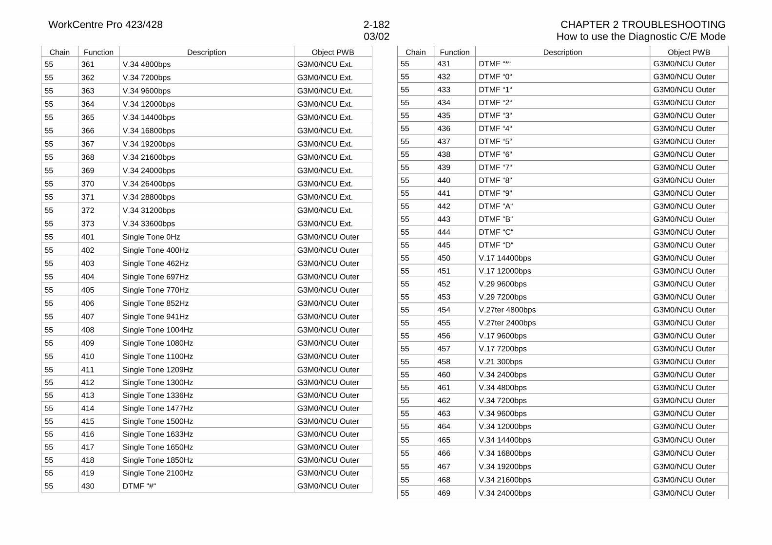
WorkCentre Pro 423/428 2-182 CHAPTER 2 TROUBLESHOOTING03/02 How to use the Diagnostic C/E Mode
Chain Function Description Object PWB
55 361 V.34 4800bps G3M0/NCU Ext.
55 362 V.34 7200bps G3M0/NCU Ext.
55 363 V.34 9600bps G3M0/NCU Ext.
55 364 V.34 12000bps G3M0/NCU Ext.
55 365 V.34 14400bps G3M0/NCU Ext.
55 366 V.34 16800bps G3M0/NCU Ext.
55 367 V.34 19200bps G3M0/NCU Ext.
55 368 V.34 21600bps G3M0/NCU Ext.
55 369 V.34 24000bps G3M0/NCU Ext.
55 370 V.34 26400bps G3M0/NCU Ext.
55 371 V.34 28800bps G3M0/NCU Ext.
55 372 V.34 31200bps G3M0/NCU Ext.
55 373 V.34 33600bps G3M0/NCU Ext.
55 401 Single Tone 0Hz G3M0/NCU Outer
55 402 Single Tone 400Hz G3M0/NCU Outer
55 403 Single Tone 462Hz G3M0/NCU Outer
55 404 Single Tone 697Hz G3M0/NCU Outer
55 405 Single Tone 770Hz G3M0/NCU Outer
55 406 Single Tone 852Hz G3M0/NCU Outer
55 407 Single Tone 941Hz G3M0/NCU Outer
55 408 Single Tone 1004Hz G3M0/NCU Outer
55 409 Single Tone 1080Hz G3M0/NCU Outer
55 410 Single Tone 1100Hz G3M0/NCU Outer
55 411 Single Tone 1209Hz G3M0/NCU Outer
55 412 Single Tone 1300Hz G3M0/NCU Outer
55 413 Single Tone 1336Hz G3M0/NCU Outer
55 414 Single Tone 1477Hz G3M0/NCU Outer
55 415 Single Tone 1500Hz G3M0/NCU Outer
55 416 Single Tone 1633Hz G3M0/NCU Outer
55 417 Single Tone 1650Hz G3M0/NCU Outer
55 418 Single Tone 1850Hz G3M0/NCU Outer
55 419 Single Tone 2100Hz G3M0/NCU Outer
55 430 DTMF “#“ G3M0/NCU Outer
Chain Function Description Object PWB
55 431 DTMF “*“ G3M0/NCU Outer
55 432 DTMF “0“ G3M0/NCU Outer
55 433 DTMF “1“ G3M0/NCU Outer
55 434 DTMF “2“ G3M0/NCU Outer
55 435 DTMF “3“ G3M0/NCU Outer
55 436 DTMF “4“ G3M0/NCU Outer
55 437 DTMF “5“ G3M0/NCU Outer
55 438 DTMF “6“ G3M0/NCU Outer
55 439 DTMF “7“ G3M0/NCU Outer
55 440 DTMF “8“ G3M0/NCU Outer
55 441 DTMF “9“ G3M0/NCU Outer
55 442 DTMF “A“ G3M0/NCU Outer
55 443 DTMF “B“ G3M0/NCU Outer
55 444 DTMF “C“ G3M0/NCU Outer
55 445 DTMF “D“ G3M0/NCU Outer
55 450 V.17 14400bps G3M0/NCU Outer
55 451 V.17 12000bps G3M0/NCU Outer
55 452 V.29 9600bps G3M0/NCU Outer
55 453 V.29 7200bps G3M0/NCU Outer
55 454 V.27ter 4800bps G3M0/NCU Outer
55 455 V.27ter 2400bps G3M0/NCU Outer
55 456 V.17 9600bps G3M0/NCU Outer
55 457 V.17 7200bps G3M0/NCU Outer
55 458 V.21 300bps G3M0/NCU Outer
55 460 V.34 2400bps G3M0/NCU Outer
55 461 V.34 4800bps G3M0/NCU Outer
55 462 V.34 7200bps G3M0/NCU Outer
55 463 V.34 9600bps G3M0/NCU Outer
55 464 V.34 12000bps G3M0/NCU Outer
55 465 V.34 14400bps G3M0/NCU Outer
55 466 V.34 16800bps G3M0/NCU Outer
55 467 V.34 19200bps G3M0/NCU Outer
55 468 V.34 21600bps G3M0/NCU Outer
55 469 V.34 24000bps G3M0/NCU Outer
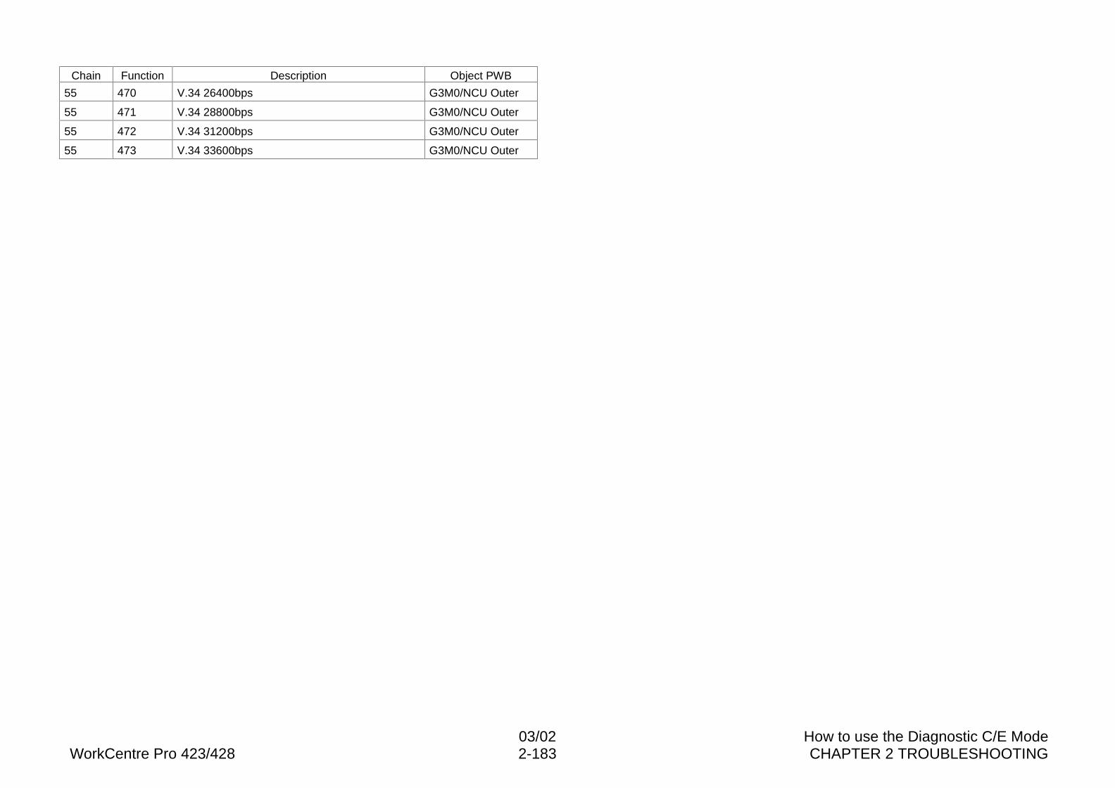
03/02 How to use the Diagnostic C/E ModeWorkCentre Pro 423/428 2-183 CHAPTER 2 TROUBLESHOOTING
Chain Function Description Object PWB
55 470 V.34 26400bps G3M0/NCU Outer
55 471 V.34 28800bps G3M0/NCU Outer
55 472 V.34 31200bps G3M0/NCU Outer
55 473 V.34 33600bps G3M0/NCU Outer
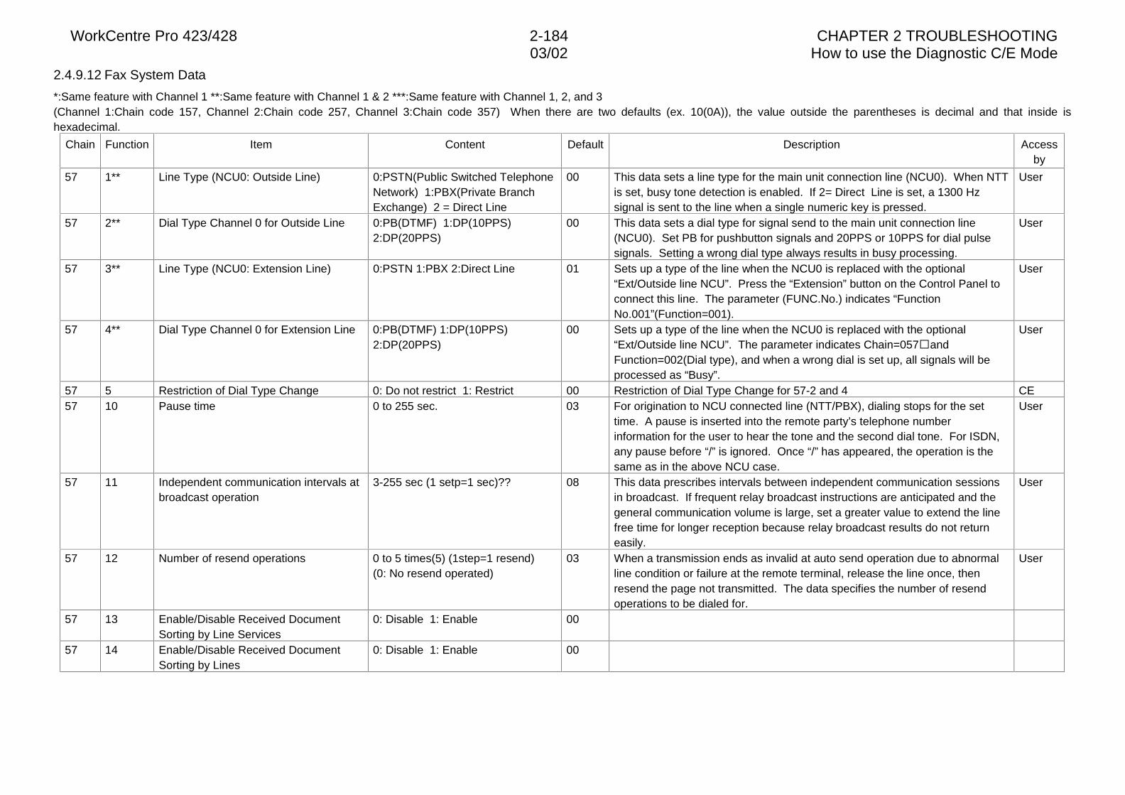
WorkCentre Pro 423/428 2-184 CHAPTER 2 TROUBLESHOOTING03/02 How to use the Diagnostic C/E Mode
2.4.9.12 Fax System Data
*:Same feature with Channel 1 **:Same feature with Channel 1 & 2 ***:Same feature with Channel 1, 2, and 3(Channel 1:Chain code 157, Channel 2:Chain code 257, Channel 3:Chain code 357) When there are two defaults (ex. 10(0A)), the value outside the parentheses is decimal and that inside ishexadecimal.
Chain Function Item Content Default Description Accessby
57 1** Line Type (NCU0: Outside Line) 0:PSTN(Public Switched TelephoneNetwork) 1:PBX(Private BranchExchange) 2 = Direct Line
00 This data sets a line type for the main unit connection line (NCU0). When NTTis set, busy tone detection is enabled. If 2= Direct Line is set, a 1300 Hzsignal is sent to the line when a single numeric key is pressed.
User
57 2** Dial Type Channel 0 for Outside Line 0:PB(DTMF) 1:DP(10PPS)2:DP(20PPS)
00 This data sets a dial type for signal send to the main unit connection line(NCU0). Set PB for pushbutton signals and 20PPS or 10PPS for dial pulsesignals. Setting a wrong dial type always results in busy processing.
User
57 3** Line Type (NCU0: Extension Line) 0:PSTN 1:PBX 2:Direct Line 01 Sets up a type of the line when the NCU0 is replaced with the optional“Ext/Outside line NCU”. Press the “Extension” button on the Control Panel toconnect this line. The parameter (FUNC.No.) indicates “FunctionNo.001”(Function=001).
User
57 4** Dial Type Channel 0 for Extension Line 0:PB(DTMF) 1:DP(10PPS)2:DP(20PPS)
00 Sets up a type of the line when the NCU0 is replaced with the optional“Ext/Outside line NCU”. The parameter indicates Chain=057�andFunction=002(Dial type), and when a wrong dial is set up, all signals will beprocessed as “Busy”.
User
57 5 Restriction of Dial Type Change 0: Do not restrict 1: Restrict 00 Restriction of Dial Type Change for 57-2 and 4 CE57 10 Pause time 0 to 255 sec. 03 For origination to NCU connected line (NTT/PBX), dialing stops for the set
time. A pause is inserted into the remote party’s telephone numberinformation for the user to hear the tone and the second dial tone. For ISDN,any pause before “/” is ignored. Once “/” has appeared, the operation is thesame as in the above NCU case.
User
57 11 Independent communication intervals atbroadcast operation
3-255 sec (1 setp=1 sec)?? 08 This data prescribes intervals between independent communication sessionsin broadcast. If frequent relay broadcast instructions are anticipated and thegeneral communication volume is large, set a greater value to extend the linefree time for longer reception because relay broadcast results do not returneasily.
User
57 12 Number of resend operations 0 to 5 times(5) (1step=1 resend)(0: No resend operated)
03 When a transmission ends as invalid at auto send operation due to abnormalline condition or failure at the remote terminal, release the line once, thenresend the page not transmitted. The data specifies the number of resendoperations to be dialed for.
User
57 13 Enable/Disable Received DocumentSorting by Line Services
0: Disable 1: Enable 00
57 14 Enable/Disable Received DocumentSorting by Lines
0: Disable 1: Enable 00
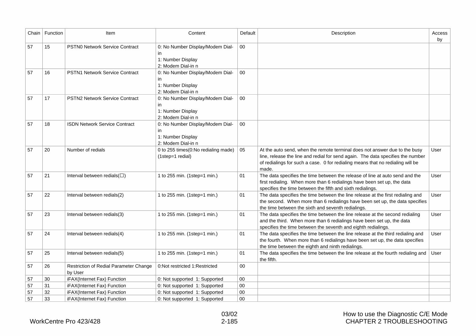
03/02 How to use the Diagnostic C/E ModeWorkCentre Pro 423/428 2-185 CHAPTER 2 TROUBLESHOOTING
Chain Function Item Content Default Description Accessby
57 15 PSTN0 Network Service Contract 0: No Number Display/Modem Dial-in1: Number Display2: Modem Dial-in n
00
57 16 PSTN1 Network Service Contract 0: No Number Display/Modem Dial-in1: Number Display2: Modem Dial-in n
00
57 17 PSTN2 Network Service Contract 0: No Number Display/Modem Dial-in1: Number Display2: Modem Dial-in n
00
57 18 ISDN Network Service Contract 0: No Number Display/Modem Dial-in1: Number Display2: Modem Dial-in n
00
57 20 Number of redials 0 to 255 times(0:No redialing made)(1step=1 redial)
05 At the auto send, when the remote terminal does not answer due to the busyline, release the line and redial for send again. The data specifies the numberof redialings for such a case. 0 for redialing means that no redialing will bemade.
User
57 21 Interval between redials(�) 1 to 255 min. (1step=1 min.) 01 The data specifies the time between the release of line at auto send and thefirst redialing. When more than 6 redialings have been set up, the dataspecifies the time between the fifth and sixth redialings.
User
57 22 Interval between redials(2) 1 to 255 min. (1step=1 min.) 01 The data specifies the time between the line release at the first redialing andthe second. When more than 6 redialings have been set up, the data specifiesthe time between the sixth and seventh redialings.
User
57 23 Interval between redials(3) 1 to 255 min. (1step=1 min.) 01 The data specifies the time between the line release at the second redialingand the third. When more than 6 redialings have been set up, the dataspecifies the time between the seventh and eighth redialings.
User
57 24 Interval between redials(4) 1 to 255 min. (1step=1 min.) 01 The data specifies the time between the line release at the third redialing andthe fourth. When more than 6 redialings have been set up, the data specifiesthe time between the eighth and ninth redialings.
User
57 25 Interval between redials(5) 1 to 255 min. (1step=1 min.) 01 The data specifies the time between the line release at the fourth redialing andthe fifth.
User
57 26 Restriction of Redial Parameter Changeby User
0:Not restricted 1:Restricted 00
57 30 iFAX(Internet Fax) Function 0: Not supported 1: Supported 0057 31 iFAX(Internet Fax) Function 0: Not supported 1: Supported 0057 32 iFAX(Internet Fax) Function 0: Not supported 1: Supported 0057 33 iFAX(Internet Fax) Function 0: Not supported 1: Supported 00
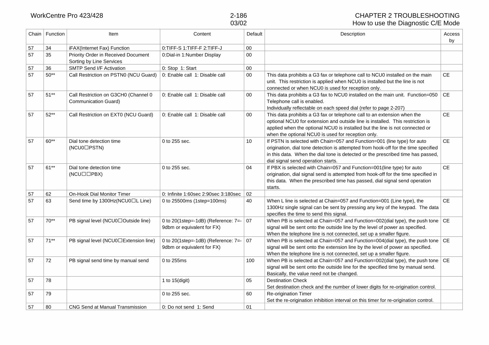
WorkCentre Pro 423/428 2-186 CHAPTER 2 TROUBLESHOOTING03/02 How to use the Diagnostic C/E Mode
Chain Function Item Content Default Description Accessby
57 34 iFAX(Internet Fax) Function 0:TIFF-S 1:TIFF-F 2:TIFF-J 0057 35 Priority Order in Received Document
Sorting by Line Services0:Dial-in 1:Number Display 00
57 36 SMTP Send I/F Activation 0: Stop 1: Start 0057 50** Call Restriction on PSTN0 (NCU Guard) 0: Enable call 1: Disable call 00 This data prohibits a G3 fax or telephone call to NCU0 installed on the main
unit. This restriction is applied when NCU0 is installed but the line is notconnected or when NCU0 is used for reception only.
CE
57 51** Call Restriction on G3CH0 (Channel 0Communication Guard)
0: Enable call 1: Disable call 00 This data prohibits a G3 fax to NCU0 installed on the main unit. Function=050Telephone call is enabled.Individually reflectable on each speed dial (refer to page 2-207)
CE
57 52** Call Restriction on EXT0 (NCU Guard) 0: Enable call 1: Disable call 00 This data prohibits a G3 fax or telephone call to an extension when theoptional NCU0 for extension and outside line is installed. This restriction isapplied when the optional NCU0 is installed but the line is not connected orwhen the optional NCU0 is used for reception only.
CE
57 60** Dial tone detection time(NCU0�PSTN)
0 to 255 sec. 10 If PSTN is selected with Chain=057 and Function=001 (line type) for autoorigination, dial tone detection is attempted from hook-off for the time specifiedin this data. When the dial tone is detected or the prescribed time has passed,dial signal send operation starts.
CE
57 61** Dial tone detection time(NCU��PBX)
0 to 255 sec. 04 If PBX is selected with Chain=057 and Function=001(line type) for autoorigination, dial signal send is attempted from hook-off for the time specified inthis data. When the prescribed time has passed, dial signal send operationstarts.
CE
57 62 On-Hook Dial Monitor Timer 0: Infinite 1:60sec 2:90sec 3:180sec 0257 63 Send time by 1300Hz(NCU0�L Line) 0 to 25500ms (1step=100ms) 40 When L line is selected at Chain=057 and Function=001 (Line type), the
1300Hz single signal can be sent by pressing any key of the keypad. The dataspecifies the time to send this signal.
CE
57 70** PB signal level (NCU0�Outside line) 0 to 20(1step=-1dB) (Reference: 7=-9dbm or equivalent for FX)
07 When PB is selected at Chain=057 and Function=002(dial type), the push tonesignal will be sent onto the outside line by the level of power as specified.When the telephone line is not connected, set up a smaller figure.
CE
57 71** PB signal level (NCU0�Extension line) 0 to 20(1step=-1dB) (Reference: 7=-9dbm or equivalent for FX)
07 When PB is selected at Chain=057 and Function=004(dial type), the push tonesignal will be sent onto the extension line by the level of power as specified.When the telephone line is not connected, set up a smaller figure.
CE
57 72 PB signal send time by manual send 0 to 255ms 100 When PB is selected at Chain=057 and Function=002(dial type), the push tonesignal will be sent onto the outside line for the specified time by manual send.Basically, the value need not be changed.
CE
57 78 1 to 15(digit) 05 Destination CheckSet destination check and the number of lower digits for re-origination control.
57 79 0 to 255 sec. 60 Re-origination TimerSet the re-origination inhibition interval on this timer for re-origination control.
57 80 CNG Send at Manual Transmission 0: Do not send 1: Send 01
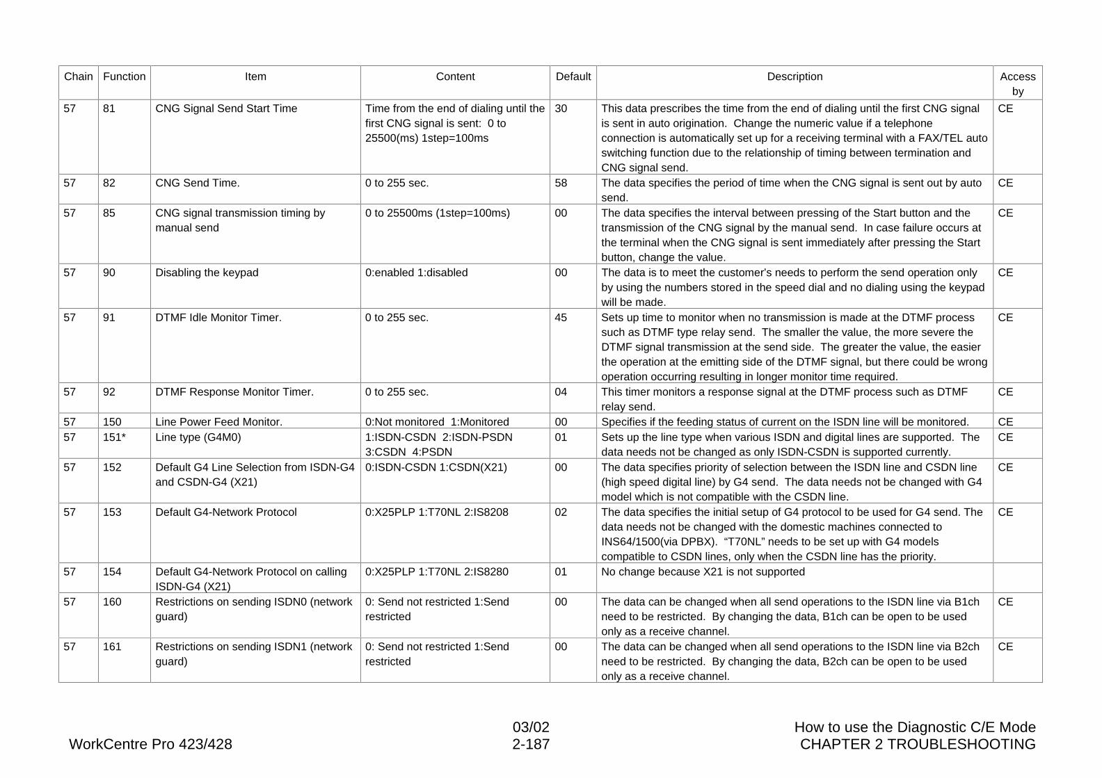
03/02 How to use the Diagnostic C/E ModeWorkCentre Pro 423/428 2-187 CHAPTER 2 TROUBLESHOOTING
Chain Function Item Content Default Description Accessby
57 81 CNG Signal Send Start Time Time from the end of dialing until thefirst CNG signal is sent: 0 to25500(ms) 1step=100ms
30 This data prescribes the time from the end of dialing until the first CNG signalis sent in auto origination. Change the numeric value if a telephoneconnection is automatically set up for a receiving terminal with a FAX/TEL autoswitching function due to the relationship of timing between termination andCNG signal send.
CE
57 82 CNG Send Time. 0 to 255 sec. 58 The data specifies the period of time when the CNG signal is sent out by autosend.
CE
57 85 CNG signal transmission timing bymanual send
0 to 25500ms (1step=100ms) 00 The data specifies the interval between pressing of the Start button and thetransmission of the CNG signal by the manual send. In case failure occurs atthe terminal when the CNG signal is sent immediately after pressing the Startbutton, change the value.
CE
57 90 Disabling the keypad 0:enabled 1:disabled 00 The data is to meet the customer’s needs to perform the send operation onlyby using the numbers stored in the speed dial and no dialing using the keypadwill be made.
CE
57 91 DTMF Idle Monitor Timer. 0 to 255 sec. 45 Sets up time to monitor when no transmission is made at the DTMF processsuch as DTMF type relay send. The smaller the value, the more severe theDTMF signal transmission at the send side. The greater the value, the easierthe operation at the emitting side of the DTMF signal, but there could be wrongoperation occurring resulting in longer monitor time required.
CE
57 92 DTMF Response Monitor Timer. 0 to 255 sec. 04 This timer monitors a response signal at the DTMF process such as DTMFrelay send.
CE
57 150 Line Power Feed Monitor. 0:Not monitored 1:Monitored 00 Specifies if the feeding status of current on the ISDN line will be monitored. CE57 151* Line type (G4M0) 1:ISDN-CSDN 2:ISDN-PSDN
3:CSDN 4:PSDN01 Sets up the line type when various ISDN and digital lines are supported. The
data needs not be changed as only ISDN-CSDN is supported currently.CE
57 152 Default G4 Line Selection from ISDN-G4and CSDN-G4 (X21)
0:ISDN-CSDN 1:CSDN(X21) 00 The data specifies priority of selection between the ISDN line and CSDN line(high speed digital line) by G4 send. The data needs not be changed with G4model which is not compatible with the CSDN line.
CE
57 153 Default G4-Network Protocol 0:X25PLP 1:T70NL 2:IS8208 02 The data specifies the initial setup of G4 protocol to be used for G4 send. Thedata needs not be changed with the domestic machines connected toINS64/1500(via DPBX). “T70NL” needs to be set up with G4 modelscompatible to CSDN lines, only when the CSDN line has the priority.
CE
57 154 Default G4-Network Protocol on callingISDN-G4 (X21)
0:X25PLP 1:T70NL 2:IS8280 01 No change because X21 is not supported
57 160 Restrictions on sending ISDN0 (networkguard)
0: Send not restricted 1:Sendrestricted
00 The data can be changed when all send operations to the ISDN line via B1chneed to be restricted. By changing the data, B1ch can be open to be usedonly as a receive channel.
CE
57 161 Restrictions on sending ISDN1 (networkguard)
0: Send not restricted 1:Sendrestricted
00 The data can be changed when all send operations to the ISDN line via B2chneed to be restricted. By changing the data, B2ch can be open to be usedonly as a receive channel.
CE
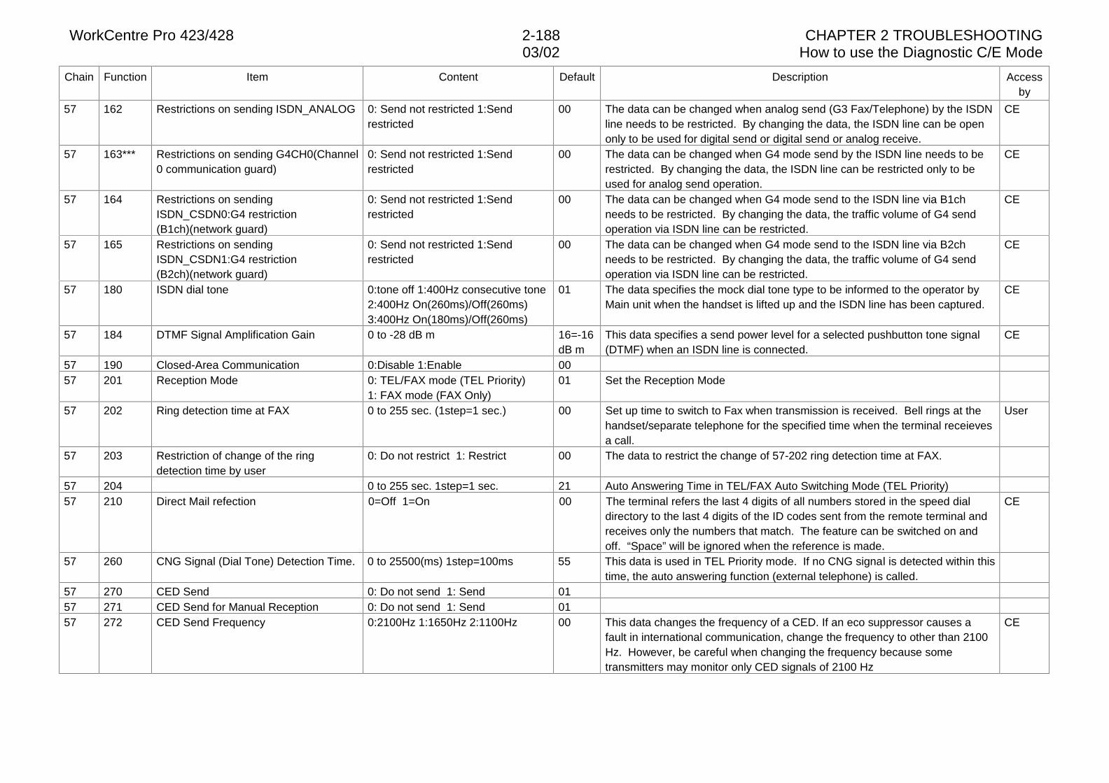
WorkCentre Pro 423/428 2-188 CHAPTER 2 TROUBLESHOOTING03/02 How to use the Diagnostic C/E Mode
Chain Function Item Content Default Description Accessby
57 162 Restrictions on sending ISDN_ANALOG 0: Send not restricted 1:Sendrestricted
00 The data can be changed when analog send (G3 Fax/Telephone) by the ISDNline needs to be restricted. By changing the data, the ISDN line can be openonly to be used for digital send or digital send or analog receive.
CE
57 163*** Restrictions on sending G4CH0(Channel0 communication guard)
0: Send not restricted 1:Sendrestricted
00 The data can be changed when G4 mode send by the ISDN line needs to berestricted. By changing the data, the ISDN line can be restricted only to beused for analog send operation.
CE
57 164 Restrictions on sendingISDN_CSDN0:G4 restriction(B1ch)(network guard)
0: Send not restricted 1:Sendrestricted
00 The data can be changed when G4 mode send to the ISDN line via B1chneeds to be restricted. By changing the data, the traffic volume of G4 sendoperation via ISDN line can be restricted.
CE
57 165 Restrictions on sendingISDN_CSDN1:G4 restriction(B2ch)(network guard)
0: Send not restricted 1:Sendrestricted
00 The data can be changed when G4 mode send to the ISDN line via B2chneeds to be restricted. By changing the data, the traffic volume of G4 sendoperation via ISDN line can be restricted.
CE
57 180 ISDN dial tone 0:tone off 1:400Hz consecutive tone2:400Hz On(260ms)/Off(260ms)3:400Hz On(180ms)/Off(260ms)
01 The data specifies the mock dial tone type to be informed to the operator byMain unit when the handset is lifted up and the ISDN line has been captured.
CE
57 184 DTMF Signal Amplification Gain 0 to -28 dB m 16=-16dB m
This data specifies a send power level for a selected pushbutton tone signal(DTMF) when an ISDN line is connected.
CE
57 190 Closed-Area Communication 0:Disable 1:Enable 0057 201 Reception Mode 0: TEL/FAX mode (TEL Priority)
1: FAX mode (FAX Only)01 Set the Reception Mode
57 202 Ring detection time at FAX 0 to 255 sec. (1step=1 sec.) 00 Set up time to switch to Fax when transmission is received. Bell rings at thehandset/separate telephone for the specified time when the terminal receievesa call.
User
57 203 Restriction of change of the ringdetection time by user
0: Do not restrict 1: Restrict 00 The data to restrict the change of 57-202 ring detection time at FAX.
57 204 0 to 255 sec. 1step=1 sec. 21 Auto Answering Time in TEL/FAX Auto Switching Mode (TEL Priority)57 210 Direct Mail refection 0=Off 1=On 00 The terminal refers the last 4 digits of all numbers stored in the speed dial
directory to the last 4 digits of the ID codes sent from the remote terminal andreceives only the numbers that match. The feature can be switched on andoff. “Space” will be ignored when the reference is made.
CE
57 260 CNG Signal (Dial Tone) Detection Time. 0 to 25500(ms) 1step=100ms 55 This data is used in TEL Priority mode. If no CNG signal is detected within thistime, the auto answering function (external telephone) is called.
57 270 CED Send 0: Do not send 1: Send 0157 271 CED Send for Manual Reception 0: Do not send 1: Send 0157 272 CED Send Frequency 0:2100Hz 1:1650Hz 2:1100Hz 00 This data changes the frequency of a CED. If an eco suppressor causes a
fault in international communication, change the frequency to other than 2100Hz. However, be careful when changing the frequency because sometransmitters may monitor only CED signals of 2100 Hz
CE
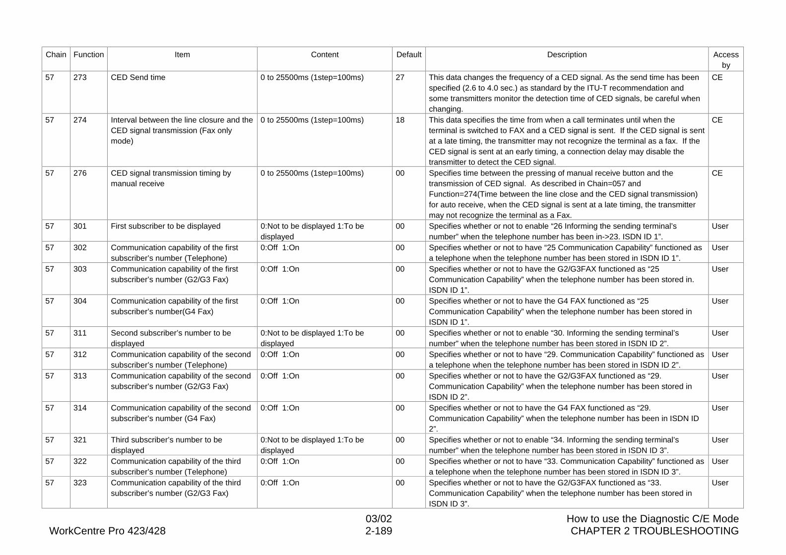
03/02 How to use the Diagnostic C/E ModeWorkCentre Pro 423/428 2-189 CHAPTER 2 TROUBLESHOOTING
Chain Function Item Content Default Description Accessby
57 273 CED Send time 0 to 25500ms (1step=100ms) 27 This data changes the frequency of a CED signal. As the send time has beenspecified (2.6 to 4.0 sec.) as standard by the ITU-T recommendation andsome transmitters monitor the detection time of CED signals, be careful whenchanging.
CE
57 274 Interval between the line closure and theCED signal transmission (Fax onlymode)
0 to 25500ms (1step=100ms) 18 This data specifies the time from when a call terminates until when theterminal is switched to FAX and a CED signal is sent. If the CED signal is sentat a late timing, the transmitter may not recognize the terminal as a fax. If theCED signal is sent at an early timing, a connection delay may disable thetransmitter to detect the CED signal.
CE
57 276 CED signal transmission timing bymanual receive
0 to 25500ms (1step=100ms) 00 Specifies time between the pressing of manual receive button and thetransmission of CED signal. As described in Chain=057 andFunction=274(Time between the line close and the CED signal transmission)for auto receive, when the CED signal is sent at a late timing, the transmittermay not recognize the terminal as a Fax.
CE
57 301 First subscriber to be displayed 0:Not to be displayed 1:To bedisplayed
00 Specifies whether or not to enable “26 Informing the sending terminal’snumber” when the telephone number has been in->23. ISDN ID 1”.
User
57 302 Communication capability of the firstsubscriber’s number (Telephone)
0:Off 1:On 00 Specifies whether or not to have “25 Communication Capability” functioned asa telephone when the telephone number has been stored in ISDN ID 1”.
User
57 303 Communication capability of the firstsubscriber’s number (G2/G3 Fax)
0:Off 1:On 00 Specifies whether or not to have the G2/G3FAX functioned as “25Communication Capability” when the telephone number has been stored in.ISDN ID 1”.
User
57 304 Communication capability of the firstsubscriber’s number(G4 Fax)
0:Off 1:On 00 Specifies whether or not to have the G4 FAX functioned as “25Communication Capability” when the telephone number has been stored inISDN ID 1”.
User
57 311 Second subscriber’s number to bedisplayed
0:Not to be displayed 1:To bedisplayed
00 Specifies whether or not to enable “30. Informing the sending terminal’snumber” when the telephone number has been stored in ISDN ID 2”.
User
57 312 Communication capability of the secondsubscriber’s number (Telephone)
0:Off 1:On 00 Specifies whether or not to have “29. Communication Capability” functioned asa telephone when the telephone number has been stored in ISDN ID 2”.
User
57 313 Communication capability of the secondsubscriber’s number (G2/G3 Fax)
0:Off 1:On 00 Specifies whether or not to have the G2/G3FAX functioned as “29.Communication Capability” when the telephone number has been stored inISDN ID 2”.
User
57 314 Communication capability of the secondsubscriber’s number (G4 Fax)
0:Off 1:On 00 Specifies whether or not to have the G4 FAX functioned as “29.Communication Capability” when the telephone number has been in ISDN ID2”.
User
57 321 Third subscriber’s number to bedisplayed
0:Not to be displayed 1:To bedisplayed
00 Specifies whether or not to enable “34. Informing the sending terminal’snumber” when the telephone number has been stored in ISDN ID 3”.
User
57 322 Communication capability of the thirdsubscriber’s number (Telephone)
0:Off 1:On 00 Specifies whether or not to have “33. Communication Capability” functioned asa telephone when the telephone number has been stored in ISDN ID 3”.
User
57 323 Communication capability of the thirdsubscriber’s number (G2/G3 Fax)
0:Off 1:On 00 Specifies whether or not to have the G2/G3FAX functioned as “33.Communication Capability” when the telephone number has been stored inISDN ID 3”.
User
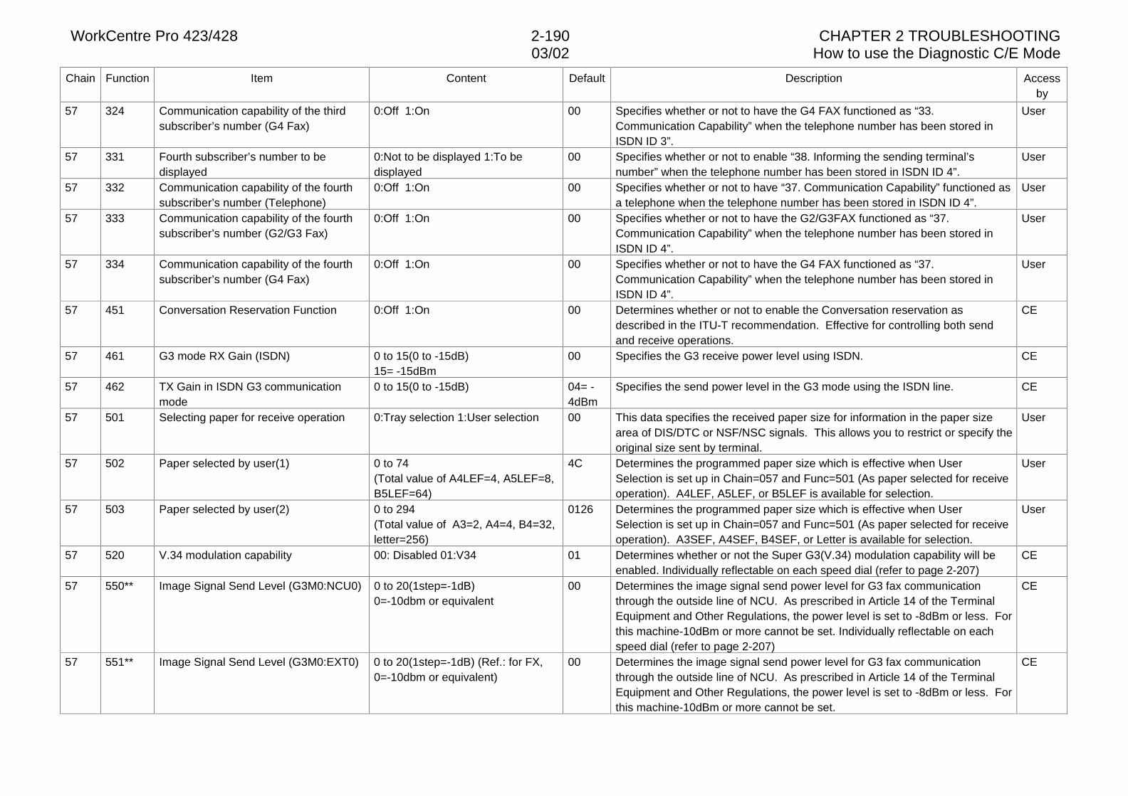
WorkCentre Pro 423/428 2-190 CHAPTER 2 TROUBLESHOOTING03/02 How to use the Diagnostic C/E Mode
Chain Function Item Content Default Description Accessby
57 324 Communication capability of the thirdsubscriber’s number (G4 Fax)
0:Off 1:On 00 Specifies whether or not to have the G4 FAX functioned as “33.Communication Capability” when the telephone number has been stored inISDN ID 3”.
User
57 331 Fourth subscriber’s number to bedisplayed
0:Not to be displayed 1:To bedisplayed
00 Specifies whether or not to enable “38. Informing the sending terminal’snumber” when the telephone number has been stored in ISDN ID 4”.
User
57 332 Communication capability of the fourthsubscriber’s number (Telephone)
0:Off 1:On 00 Specifies whether or not to have “37. Communication Capability” functioned asa telephone when the telephone number has been stored in ISDN ID 4”.
User
57 333 Communication capability of the fourthsubscriber’s number (G2/G3 Fax)
0:Off 1:On 00 Specifies whether or not to have the G2/G3FAX functioned as “37.Communication Capability” when the telephone number has been stored inISDN ID 4”.
User
57 334 Communication capability of the fourthsubscriber’s number (G4 Fax)
0:Off 1:On 00 Specifies whether or not to have the G4 FAX functioned as “37.Communication Capability” when the telephone number has been stored inISDN ID 4”.
User
57 451 Conversation Reservation Function 0:Off 1:On 00 Determines whether or not to enable the Conversation reservation asdescribed in the ITU-T recommendation. Effective for controlling both sendand receive operations.
CE
57 461 G3 mode RX Gain (ISDN) 0 to 15(0 to -15dB)15= -15dBm
00 Specifies the G3 receive power level using ISDN. CE
57 462 TX Gain in ISDN G3 communicationmode
0 to 15(0 to -15dB) 04= -4dBm
Specifies the send power level in the G3 mode using the ISDN line. CE
57 501 Selecting paper for receive operation 0:Tray selection 1:User selection 00 This data specifies the received paper size for information in the paper sizearea of DIS/DTC or NSF/NSC signals. This allows you to restrict or specify theoriginal size sent by terminal.
User
57 502 Paper selected by user(1) 0 to 74(Total value of A4LEF=4, A5LEF=8,B5LEF=64)
4C Determines the programmed paper size which is effective when UserSelection is set up in Chain=057 and Func=501 (As paper selected for receiveoperation). A4LEF, A5LEF, or B5LEF is available for selection.
User
57 503 Paper selected by user(2) 0 to 294(Total value of A3=2, A4=4, B4=32,letter=256)
0126 Determines the programmed paper size which is effective when UserSelection is set up in Chain=057 and Func=501 (As paper selected for receiveoperation). A3SEF, A4SEF, B4SEF, or Letter is available for selection.
User
57 520 V.34 modulation capability 00: Disabled 01:V34 01 Determines whether or not the Super G3(V.34) modulation capability will beenabled. Individually reflectable on each speed dial (refer to page 2-207)
CE
57 550** Image Signal Send Level (G3M0:NCU0) 0 to 20(1step=-1dB)0=-10dbm or equivalent
00 Determines the image signal send power level for G3 fax communicationthrough the outside line of NCU. As prescribed in Article 14 of the TerminalEquipment and Other Regulations, the power level is set to -8dBm or less. Forthis machine-10dBm or more cannot be set. Individually reflectable on eachspeed dial (refer to page 2-207)
CE
57 551** Image Signal Send Level (G3M0:EXT0) 0 to 20(1step=-1dB) (Ref.: for FX,0=-10dbm or equivalent)
00 Determines the image signal send power level for G3 fax communicationthrough the outside line of NCU. As prescribed in Article 14 of the TerminalEquipment and Other Regulations, the power level is set to -8dBm or less. Forthis machine-10dBm or more cannot be set.
CE
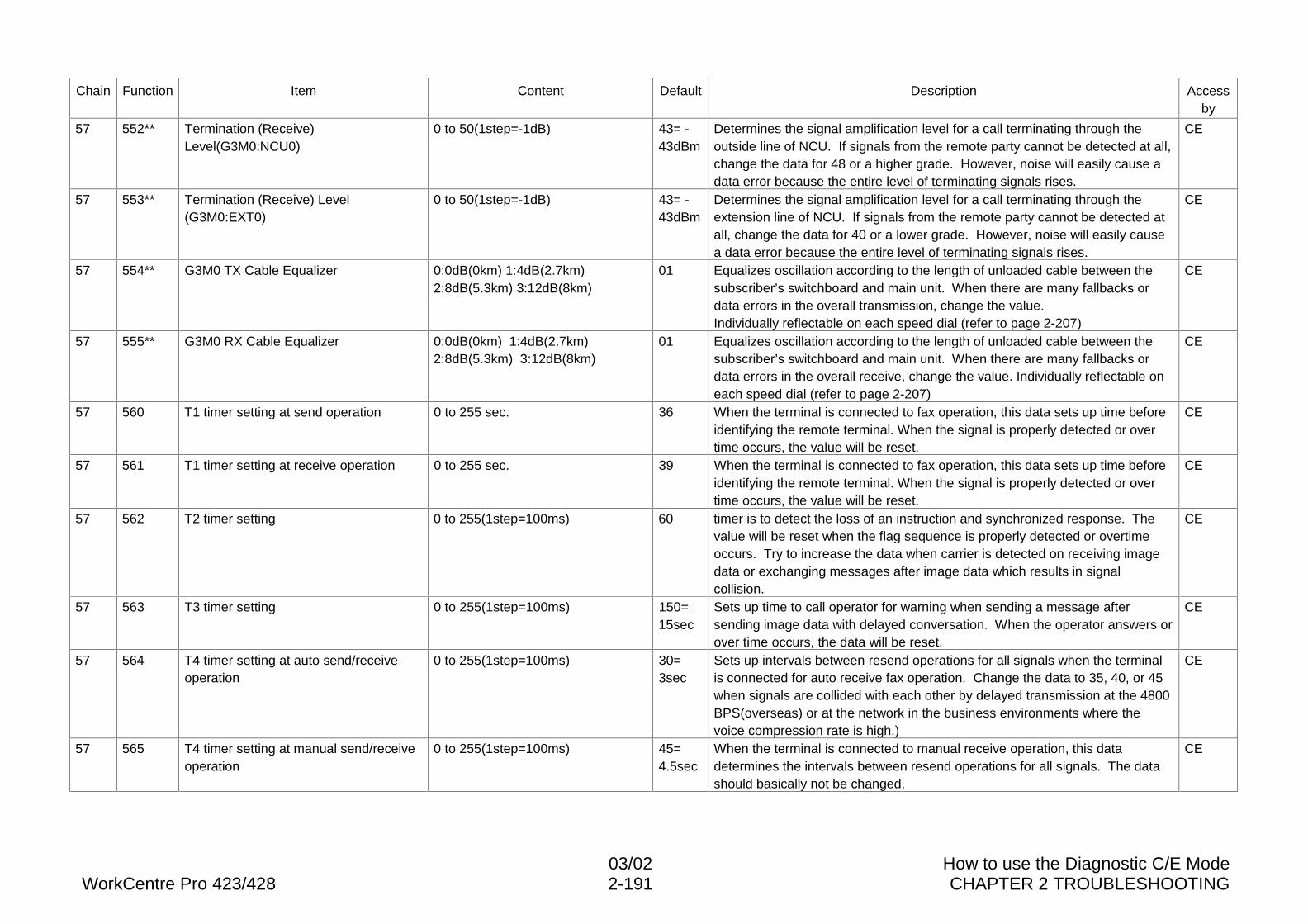
03/02 How to use the Diagnostic C/E ModeWorkCentre Pro 423/428 2-191 CHAPTER 2 TROUBLESHOOTING
Chain Function Item Content Default Description Accessby
57 552** Termination (Receive)Level(G3M0:NCU0)
0 to 50(1step=-1dB) 43= -43dBm
Determines the signal amplification level for a call terminating through theoutside line of NCU. If signals from the remote party cannot be detected at all,change the data for 48 or a higher grade. However, noise will easily cause adata error because the entire level of terminating signals rises.
CE
57 553** Termination (Receive) Level(G3M0:EXT0)
0 to 50(1step=-1dB) 43= -43dBm
Determines the signal amplification level for a call terminating through theextension line of NCU. If signals from the remote party cannot be detected atall, change the data for 40 or a lower grade. However, noise will easily causea data error because the entire level of terminating signals rises.
CE
57 554** G3M0 TX Cable Equalizer 0:0dB(0km) 1:4dB(2.7km)2:8dB(5.3km) 3:12dB(8km)
01 Equalizes oscillation according to the length of unloaded cable between thesubscriber’s switchboard and main unit. When there are many fallbacks ordata errors in the overall transmission, change the value.Individually reflectable on each speed dial (refer to page 2-207)
CE
57 555** G3M0 RX Cable Equalizer 0:0dB(0km) 1:4dB(2.7km)2:8dB(5.3km) 3:12dB(8km)
01 Equalizes oscillation according to the length of unloaded cable between thesubscriber’s switchboard and main unit. When there are many fallbacks ordata errors in the overall receive, change the value. Individually reflectable oneach speed dial (refer to page 2-207)
CE
57 560 T1 timer setting at send operation 0 to 255 sec. 36 When the terminal is connected to fax operation, this data sets up time beforeidentifying the remote terminal. When the signal is properly detected or overtime occurs, the value will be reset.
CE
57 561 T1 timer setting at receive operation 0 to 255 sec. 39 When the terminal is connected to fax operation, this data sets up time beforeidentifying the remote terminal. When the signal is properly detected or overtime occurs, the value will be reset.
CE
57 562 T2 timer setting 0 to 255(1step=100ms) 60 timer is to detect the loss of an instruction and synchronized response. Thevalue will be reset when the flag sequence is properly detected or overtimeoccurs. Try to increase the data when carrier is detected on receiving imagedata or exchanging messages after image data which results in signalcollision.
CE
57 563 T3 timer setting 0 to 255(1step=100ms) 150=15sec
Sets up time to call operator for warning when sending a message aftersending image data with delayed conversation. When the operator answers orover time occurs, the data will be reset.
CE
57 564 T4 timer setting at auto send/receiveoperation
0 to 255(1step=100ms) 30=3sec
Sets up intervals between resend operations for all signals when the terminalis connected for auto receive fax operation. Change the data to 35, 40, or 45when signals are collided with each other by delayed transmission at the 4800BPS(overseas) or at the network in the business environments where thevoice compression rate is high.)
CE
57 565 T4 timer setting at manual send/receiveoperation
0 to 255(1step=100ms) 45=4.5sec
When the terminal is connected to manual receive operation, this datadetermines the intervals between resend operations for all signals. The datashould basically not be changed.
CE
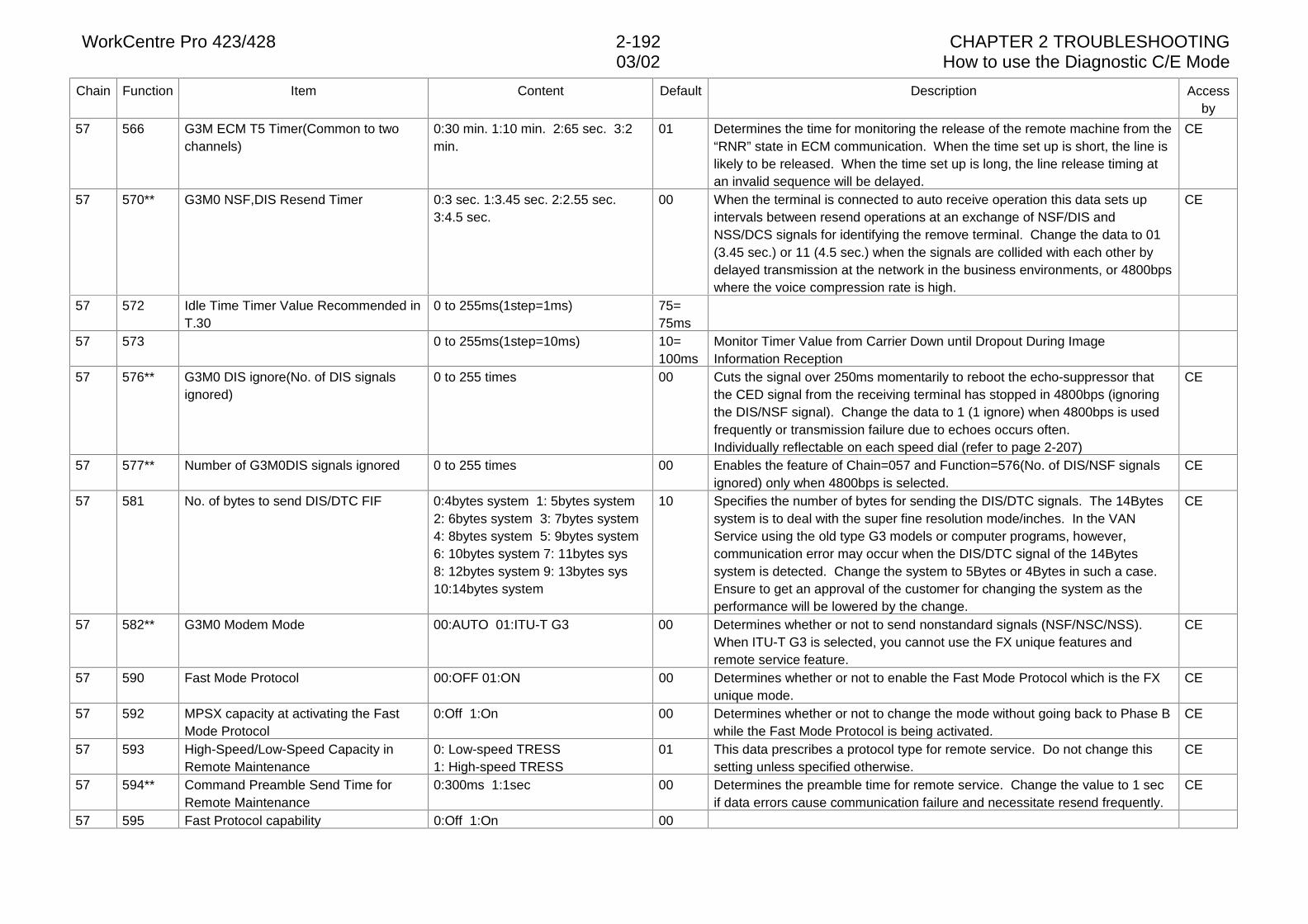
WorkCentre Pro 423/428 2-192 CHAPTER 2 TROUBLESHOOTING03/02 How to use the Diagnostic C/E Mode
Chain Function Item Content Default Description Accessby
57 566 G3M ECM T5 Timer(Common to twochannels)
0:30 min. 1:10 min. 2:65 sec. 3:2min.
01 Determines the time for monitoring the release of the remote machine from the“RNR” state in ECM communication. When the time set up is short, the line islikely to be released. When the time set up is long, the line release timing atan invalid sequence will be delayed.
CE
57 570** G3M0 NSF,DIS Resend Timer 0:3 sec. 1:3.45 sec. 2:2.55 sec.3:4.5 sec.
00 When the terminal is connected to auto receive operation this data sets upintervals between resend operations at an exchange of NSF/DIS andNSS/DCS signals for identifying the remove terminal. Change the data to 01(3.45 sec.) or 11 (4.5 sec.) when the signals are collided with each other bydelayed transmission at the network in the business environments, or 4800bpswhere the voice compression rate is high.
CE
57 572 Idle Time Timer Value Recommended inT.30
0 to 255ms(1step=1ms) 75=75ms
57 573 0 to 255ms(1step=10ms) 10=100ms
Monitor Timer Value from Carrier Down until Dropout During ImageInformation Reception
57 576** G3M0 DIS ignore(No. of DIS signalsignored)
0 to 255 times 00 Cuts the signal over 250ms momentarily to reboot the echo-suppressor thatthe CED signal from the receiving terminal has stopped in 4800bps (ignoringthe DIS/NSF signal). Change the data to 1 (1 ignore) when 4800bps is usedfrequently or transmission failure due to echoes occurs often.Individually reflectable on each speed dial (refer to page 2-207)
CE
57 577** Number of G3M0DIS signals ignored 0 to 255 times 00 Enables the feature of Chain=057 and Function=576(No. of DIS/NSF signalsignored) only when 4800bps is selected.
CE
57 581 No. of bytes to send DIS/DTC FIF 0:4bytes system 1: 5bytes system2: 6bytes system 3: 7bytes system4: 8bytes system 5: 9bytes system6: 10bytes system 7: 11bytes sys8: 12bytes system 9: 13bytes sys10:14bytes system
10 Specifies the number of bytes for sending the DIS/DTC signals. The 14Bytessystem is to deal with the super fine resolution mode/inches. In the VANService using the old type G3 models or computer programs, however,communication error may occur when the DIS/DTC signal of the 14Bytessystem is detected. Change the system to 5Bytes or 4Bytes in such a case.Ensure to get an approval of the customer for changing the system as theperformance will be lowered by the change.
CE
57 582** G3M0 Modem Mode 00:AUTO 01:ITU-T G3 00 Determines whether or not to send nonstandard signals (NSF/NSC/NSS).When ITU-T G3 is selected, you cannot use the FX unique features andremote service feature.
CE
57 590 Fast Mode Protocol 00:OFF 01:ON 00 Determines whether or not to enable the Fast Mode Protocol which is the FXunique mode.
CE
57 592 MPSX capacity at activating the FastMode Protocol
0:Off 1:On 00 Determines whether or not to change the mode without going back to Phase Bwhile the Fast Mode Protocol is being activated.
CE
57 593 High-Speed/Low-Speed Capacity inRemote Maintenance
0: Low-speed TRESS1: High-speed TRESS
01 This data prescribes a protocol type for remote service. Do not change thissetting unless specified otherwise.
CE
57 594** Command Preamble Send Time forRemote Maintenance
0:300ms 1:1sec 00 Determines the preamble time for remote service. Change the value to 1 secif data errors cause communication failure and necessitate resend frequently.
CE
57 595 Fast Protocol capability 0:Off 1:On 00
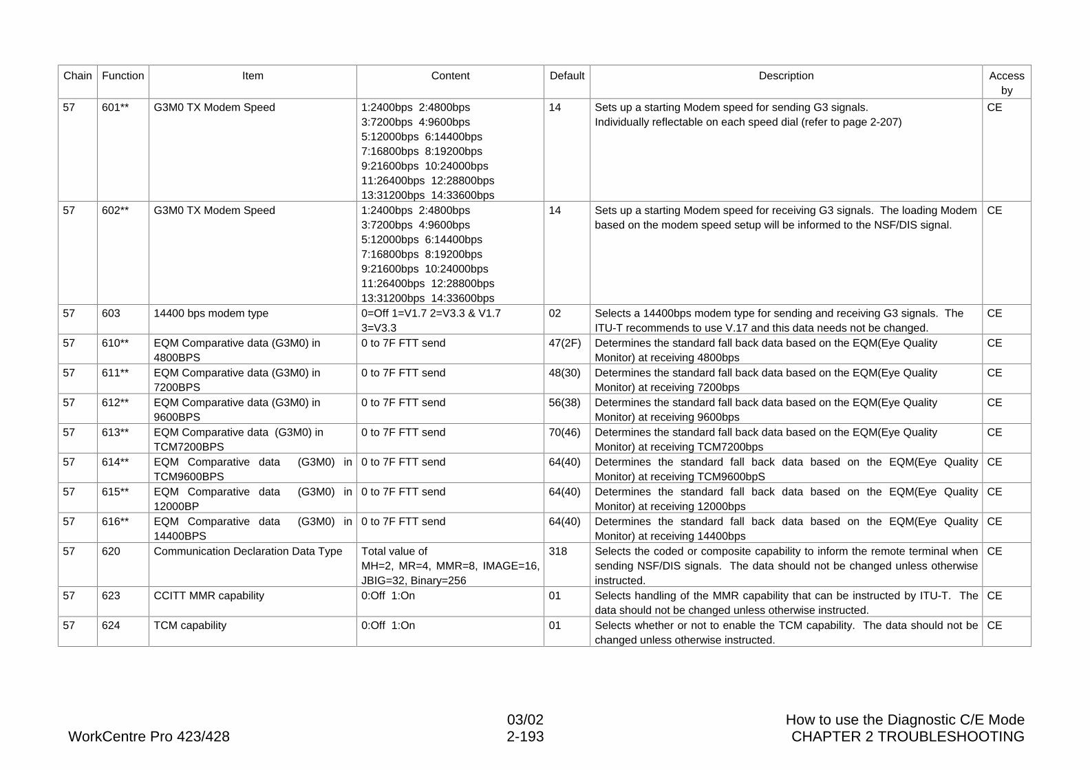
03/02 How to use the Diagnostic C/E ModeWorkCentre Pro 423/428 2-193 CHAPTER 2 TROUBLESHOOTING
Chain Function Item Content Default Description Accessby
57 601** G3M0 TX Modem Speed 1:2400bps 2:4800bps3:7200bps 4:9600bps5:12000bps 6:14400bps7:16800bps 8:19200bps9:21600bps 10:24000bps11:26400bps 12:28800bps13:31200bps 14:33600bps
14 Sets up a starting Modem speed for sending G3 signals.Individually reflectable on each speed dial (refer to page 2-207)
CE
57 602** G3M0 TX Modem Speed 1:2400bps 2:4800bps3:7200bps 4:9600bps5:12000bps 6:14400bps7:16800bps 8:19200bps9:21600bps 10:24000bps11:26400bps 12:28800bps13:31200bps 14:33600bps
14 Sets up a starting Modem speed for receiving G3 signals. The loading Modembased on the modem speed setup will be informed to the NSF/DIS signal.
CE
57 603 14400 bps modem type 0=Off 1=V1.7 2=V3.3 & V1.73=V3.3
02 Selects a 14400bps modem type for sending and receiving G3 signals. TheITU-T recommends to use V.17 and this data needs not be changed.
CE
57 610** EQM Comparative data (G3M0) in4800BPS
0 to 7F FTT send 47(2F) Determines the standard fall back data based on the EQM(Eye QualityMonitor) at receiving 4800bps
CE
57 611** EQM Comparative data (G3M0) in7200BPS
0 to 7F FTT send 48(30) Determines the standard fall back data based on the EQM(Eye QualityMonitor) at receiving 7200bps
CE
57 612** EQM Comparative data (G3M0) in9600BPS
0 to 7F FTT send 56(38) Determines the standard fall back data based on the EQM(Eye QualityMonitor) at receiving 9600bps
CE
57 613** EQM Comparative data (G3M0) inTCM7200BPS
0 to 7F FTT send 70(46) Determines the standard fall back data based on the EQM(Eye QualityMonitor) at receiving TCM7200bps
CE
57 614** EQM Comparative data (G3M0) inTCM9600BPS
0 to 7F FTT send 64(40) Determines the standard fall back data based on the EQM(Eye QualityMonitor) at receiving TCM9600bpS
CE
57 615** EQM Comparative data (G3M0) in12000BP
0 to 7F FTT send 64(40) Determines the standard fall back data based on the EQM(Eye QualityMonitor) at receiving 12000bps
CE
57 616** EQM Comparative data (G3M0) in14400BPS
0 to 7F FTT send 64(40) Determines the standard fall back data based on the EQM(Eye QualityMonitor) at receiving 14400bps
CE
57 620 Communication Declaration Data Type Total value ofMH=2, MR=4, MMR=8, IMAGE=16,JBIG=32, Binary=256
318 Selects the coded or composite capability to inform the remote terminal whensending NSF/DIS signals. The data should not be changed unless otherwiseinstructed.
CE
57 623 CCITT MMR capability 0:Off 1:On 01 Selects handling of the MMR capability that can be instructed by ITU-T. Thedata should not be changed unless otherwise instructed.
CE
57 624 TCM capability 0:Off 1:On 01 Selects whether or not to enable the TCM capability. The data should not bechanged unless otherwise instructed.
CE
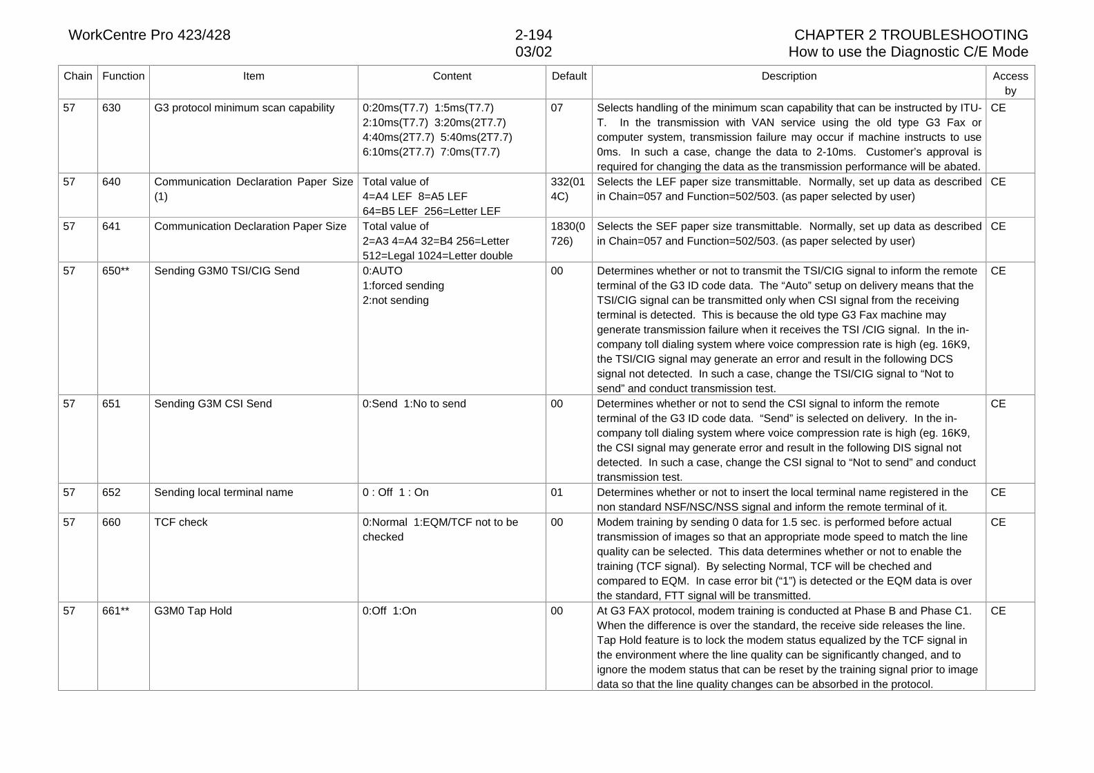
WorkCentre Pro 423/428 2-194 CHAPTER 2 TROUBLESHOOTING03/02 How to use the Diagnostic C/E Mode
Chain Function Item Content Default Description Accessby
57 630 G3 protocol minimum scan capability 0:20ms(T7.7) 1:5ms(T7.7)2:10ms(T7.7) 3:20ms(2T7.7)4:40ms(2T7.7) 5:40ms(2T7.7)6:10ms(2T7.7) 7:0ms(T7.7)
07 Selects handling of the minimum scan capability that can be instructed by ITU-T. In the transmission with VAN service using the old type G3 Fax orcomputer system, transmission failure may occur if machine instructs to use0ms. In such a case, change the data to 2-10ms. Customer’s approval isrequired for changing the data as the transmission performance will be abated.
CE
57 640 Communication Declaration Paper Size(1)
Total value of4=A4 LEF 8=A5 LEF 64=B5 LEF 256=Letter LEF
332(014C)
Selects the LEF paper size transmittable. Normally, set up data as describedin Chain=057 and Function=502/503. (as paper selected by user)
CE
57 641 Communication Declaration Paper Size Total value of2=A3 4=A4 32=B4 256=Letter512=Legal 1024=Letter double
1830(0726)
Selects the SEF paper size transmittable. Normally, set up data as describedin Chain=057 and Function=502/503. (as paper selected by user)
CE
57 650** Sending G3M0 TSI/CIG Send 0:AUTO1:forced sending2:not sending
00 Determines whether or not to transmit the TSI/CIG signal to inform the remoteterminal of the G3 ID code data. The “Auto” setup on delivery means that theTSI/CIG signal can be transmitted only when CSI signal from the receivingterminal is detected. This is because the old type G3 Fax machine maygenerate transmission failure when it receives the TSI /CIG signal. In the in-company toll dialing system where voice compression rate is high (eg. 16K9,the TSI/CIG signal may generate an error and result in the following DCSsignal not detected. In such a case, change the TSI/CIG signal to “Not tosend” and conduct transmission test.
CE
57 651 Sending G3M CSI Send 0:Send 1:No to send 00 Determines whether or not to send the CSI signal to inform the remoteterminal of the G3 ID code data. “Send” is selected on delivery. In the in-company toll dialing system where voice compression rate is high (eg. 16K9,the CSI signal may generate error and result in the following DIS signal notdetected. In such a case, change the CSI signal to “Not to send” and conducttransmission test.
CE
57 652 Sending local terminal name 0 : Off 1 : On 01 Determines whether or not to insert the local terminal name registered in thenon standard NSF/NSC/NSS signal and inform the remote terminal of it.
CE
57 660 TCF check 0:Normal 1:EQM/TCF not to bechecked
00 Modem training by sending 0 data for 1.5 sec. is performed before actualtransmission of images so that an appropriate mode speed to match the linequality can be selected. This data determines whether or not to enable thetraining (TCF signal). By selecting Normal, TCF will be cheched andcompared to EQM. In case error bit (“1”) is detected or the EQM data is overthe standard, FTT signal will be transmitted.
CE
57 661** G3M0 Tap Hold 0:Off 1:On 00 At G3 FAX protocol, modem training is conducted at Phase B and Phase C1.When the difference is over the standard, the receive side releases the line.Tap Hold feature is to lock the modem status equalized by the TCF signal inthe environment where the line quality can be significantly changed, and toignore the modem status that can be reset by the training signal prior to imagedata so that the line quality changes can be absorbed in the protocol.
CE
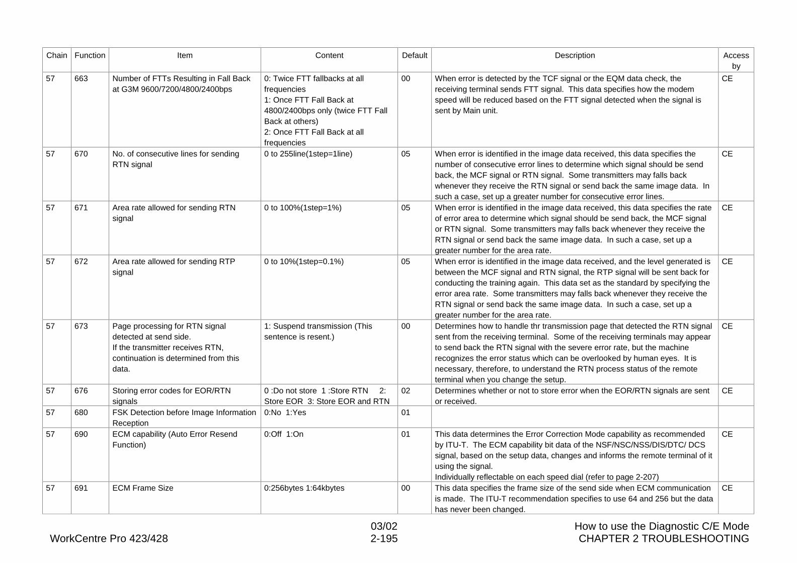
03/02 How to use the Diagnostic C/E ModeWorkCentre Pro 423/428 2-195 CHAPTER 2 TROUBLESHOOTING
Chain Function Item Content Default Description Accessby
57 663 Number of FTTs Resulting in Fall Backat G3M 9600/7200/4800/2400bps
0: Twice FTT fallbacks at allfrequencies1: Once FTT Fall Back at4800/2400bps only (twice FTT FallBack at others)2: Once FTT Fall Back at allfrequencies
00 When error is detected by the TCF signal or the EQM data check, thereceiving terminal sends FTT signal. This data specifies how the modemspeed will be reduced based on the FTT signal detected when the signal issent by Main unit.
CE
57 670 No. of consecutive lines for sendingRTN signal
0 to 255line(1step=1line) 05 When error is identified in the image data received, this data specifies thenumber of consecutive error lines to determine which signal should be sendback, the MCF signal or RTN signal. Some transmitters may falls backwhenever they receive the RTN signal or send back the same image data. Insuch a case, set up a greater number for consecutive error lines.
CE
57 671 Area rate allowed for sending RTNsignal
0 to 100%(1step=1%) 05 When error is identified in the image data received, this data specifies the rateof error area to determine which signal should be send back, the MCF signalor RTN signal. Some transmitters may falls back whenever they receive theRTN signal or send back the same image data. In such a case, set up agreater number for the area rate.
CE
57 672 Area rate allowed for sending RTPsignal
0 to 10%(1step=0.1%) 05 When error is identified in the image data received, and the level generated isbetween the MCF signal and RTN signal, the RTP signal will be sent back forconducting the training again. This data set as the standard by specifying theerror area rate. Some transmitters may falls back whenever they receive theRTN signal or send back the same image data. In such a case, set up agreater number for the area rate.
CE
57 673 Page processing for RTN signaldetected at send side.If the transmitter receives RTN,continuation is determined from thisdata.
1: Suspend transmission (Thissentence is resent.)
00 Determines how to handle thr transmission page that detected the RTN signalsent from the receiving terminal. Some of the receiving terminals may appearto send back the RTN signal with the severe error rate, but the machinerecognizes the error status which can be overlooked by human eyes. It isnecessary, therefore, to understand the RTN process status of the remoteterminal when you change the setup.
CE
57 676 Storing error codes for EOR/RTNsignals
0 :Do not store 1 :Store RTN 2:Store EOR 3: Store EOR and RTN
02 Determines whether or not to store error when the EOR/RTN signals are sentor received.
CE
57 680 FSK Detection before Image InformationReception
0:No 1:Yes 01
57 690 ECM capability (Auto Error ResendFunction)
0:Off 1:On 01 This data determines the Error Correction Mode capability as recommendedby ITU-T. The ECM capability bit data of the NSF/NSC/NSS/DIS/DTC/ DCSsignal, based on the setup data, changes and informs the remote terminal of itusing the signal.Individually reflectable on each speed dial (refer to page 2-207)
CE
57 691 ECM Frame Size 0:256bytes 1:64kbytes 00 This data specifies the frame size of the send side when ECM communicationis made. The ITU-T recommendation specifies to use 64 and 256 but the datahas never been changed.
CE
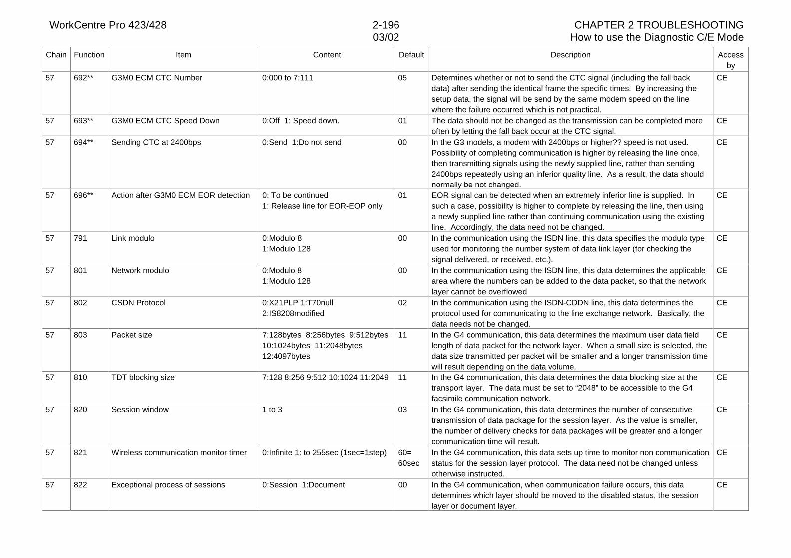
WorkCentre Pro 423/428 2-196 CHAPTER 2 TROUBLESHOOTING03/02 How to use the Diagnostic C/E Mode
Chain Function Item Content Default Description Accessby
57 692** G3M0 ECM CTC Number 0:000 to 7:111 05 Determines whether or not to send the CTC signal (including the fall backdata) after sending the identical frame the specific times. By increasing thesetup data, the signal will be send by the same modem speed on the linewhere the failure occurred which is not practical.
CE
57 693** G3M0 ECM CTC Speed Down 0:Off 1: Speed down. 01 The data should not be changed as the transmission can be completed moreoften by letting the fall back occur at the CTC signal.
CE
57 694** Sending CTC at 2400bps 0:Send 1:Do not send 00 In the G3 models, a modem with 2400bps or higher?? speed is not used.Possibility of completing communication is higher by releasing the line once,then transmitting signals using the newly supplied line, rather than sending2400bps repeatedly using an inferior quality line. As a result, the data shouldnormally be not changed.
CE
57 696** Action after G3M0 ECM EOR detection 0: To be continued1: Release line for EOR-EOP only
01 EOR signal can be detected when an extremely inferior line is supplied. Insuch a case, possibility is higher to complete by releasing the line, then usinga newly supplied line rather than continuing communication using the existingline. Accordingly, the data need not be changed.
CE
57 791 Link modulo 0:Modulo 81:Modulo 128
00 In the communication using the ISDN line, this data specifies the modulo typeused for monitoring the number system of data link layer (for checking thesignal delivered, or received, etc.).
CE
57 801 Network modulo 0:Modulo 81:Modulo 128
00 In the communication using the ISDN line, this data determines the applicablearea where the numbers can be added to the data packet, so that the networklayer cannot be overflowed
CE
57 802 CSDN Protocol 0:X21PLP 1:T70null2:IS8208modified
02 In the communication using the ISDN-CDDN line, this data determines theprotocol used for communicating to the line exchange network. Basically, thedata needs not be changed.
CE
57 803 Packet size 7:128bytes 8:256bytes 9:512bytes10:1024bytes 11:2048bytes12:4097bytes
11 In the G4 communication, this data determines the maximum user data fieldlength of data packet for the network layer. When a small size is selected, thedata size transmitted per packet will be smaller and a longer transmission timewill result depending on the data volume.
CE
57 810 TDT blocking size 7:128 8:256 9:512 10:1024 11:2049 11 In the G4 communication, this data determines the data blocking size at thetransport layer. The data must be set to “2048” to be accessible to the G4facsimile communication network.
CE
57 820 Session window 1 to 3 03 In the G4 communication, this data determines the number of consecutivetransmission of data package for the session layer. As the value is smaller,the number of delivery checks for data packages will be greater and a longercommunication time will result.
CE
57 821 Wireless communication monitor timer 0:Infinite 1: to 255sec (1sec=1step) 60=60sec
In the G4 communication, this data sets up time to monitor non communicationstatus for the session layer protocol. The data need not be changed unlessotherwise instructed.
CE
57 822 Exceptional process of sessions 0:Session 1:Document 00 In the G4 communication, when communication failure occurs, this datadetermines which layer should be moved to the disabled status, the sessionlayer or document layer.
CE
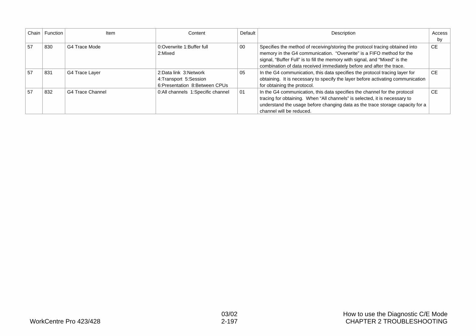
03/02 How to use the Diagnostic C/E ModeWorkCentre Pro 423/428 2-197 CHAPTER 2 TROUBLESHOOTING
Chain Function Item Content Default Description Accessby
57 830 G4 Trace Mode 0:Overwrite 1:Buffer full2:Mixed
00 Specifies the method of receiving/storing the protocol tracing obtained intomemory in the G4 communication. “Overwrite” is a FIFO method for thesignal, “Buffer Full” is to fill the memory with signal, and “Mixed” is thecombination of data received immediately before and after the trace.
CE
57 831 G4 Trace Layer 2:Data link 3:Network4:Transport 5:Session6:Presentation 8:Between CPUs
05 In the G4 communication, this data specifies the protocol tracing layer forobtaining. It is necessary to specify the layer before activating communicationfor obtaining the protocol.
CE
57 832 G4 Trace Channel 0:All channels 1:Specific channel 01 In the G4 communication, this data specifies the channel for the protocoltracing for obtaining. When “All channels” is selected, it is necessary tounderstand the usage before changing data as the trace storage capacity for achannel will be reduced.
CE
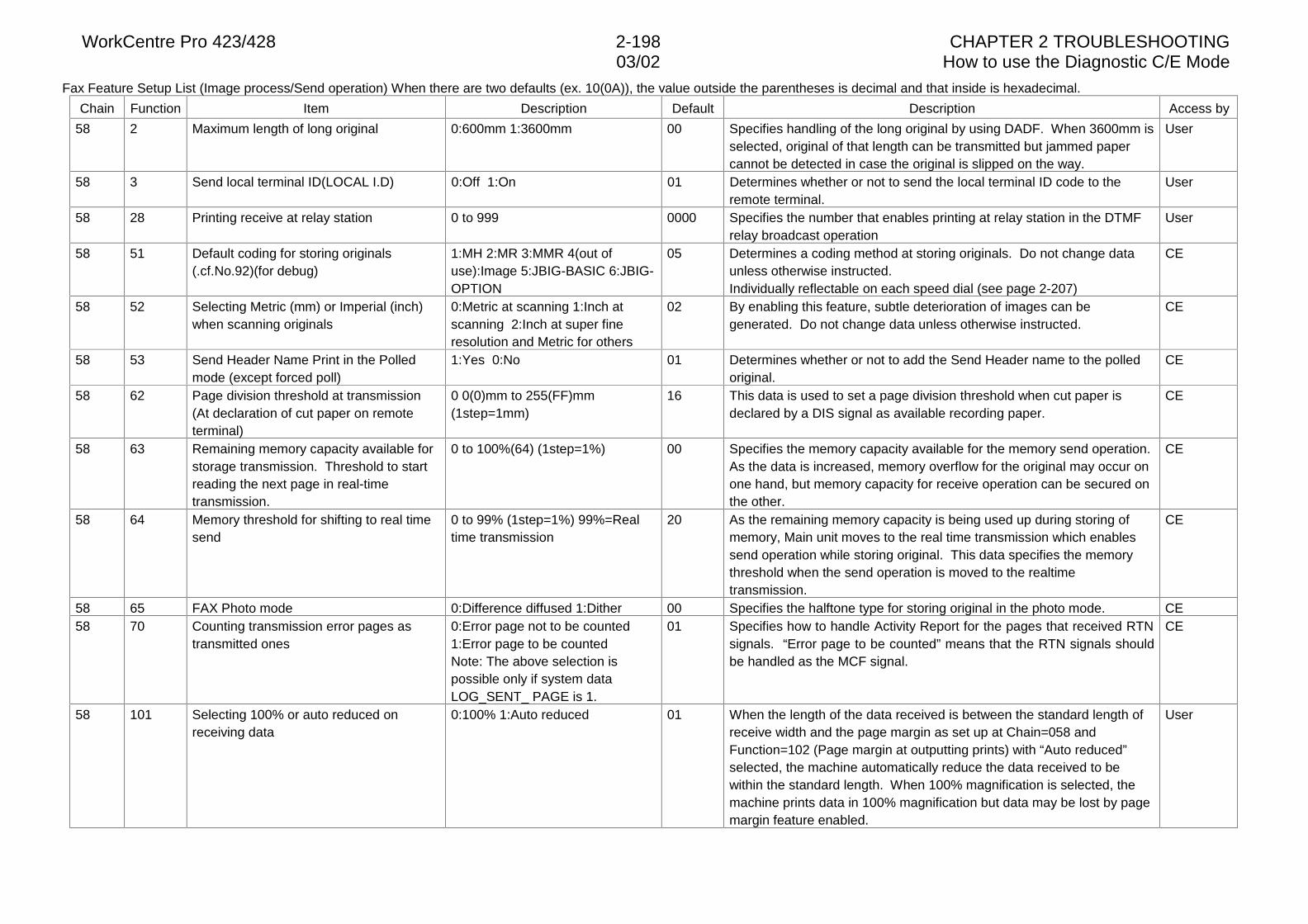
WorkCentre Pro 423/428 2-198 CHAPTER 2 TROUBLESHOOTING03/02 How to use the Diagnostic C/E Mode
Fax Feature Setup List (Image process/Send operation) When there are two defaults (ex. 10(0A)), the value outside the parentheses is decimal and that inside is hexadecimal.
Chain Function Item Description Default Description Access by
58 2 Maximum length of long original 0:600mm 1:3600mm 00 Specifies handling of the long original by using DADF. When 3600mm isselected, original of that length can be transmitted but jammed papercannot be detected in case the original is slipped on the way.
User
58 3 Send local terminal ID(LOCAL I.D) 0:Off 1:On 01 Determines whether or not to send the local terminal ID code to theremote terminal.
User
58 28 Printing receive at relay station 0 to 999 0000 Specifies the number that enables printing at relay station in the DTMFrelay broadcast operation
User
58 51 Default coding for storing originals(.cf.No.92)(for debug)
1:MH 2:MR 3:MMR 4(out ofuse):Image 5:JBIG-BASIC 6:JBIG-OPTION
05 Determines a coding method at storing originals. Do not change dataunless otherwise instructed.Individually reflectable on each speed dial (see page 2-207)
CE
58 52 Selecting Metric (mm) or Imperial (inch)when scanning originals
0:Metric at scanning 1:Inch atscanning 2:Inch at super fineresolution and Metric for others
02 By enabling this feature, subtle deterioration of images can begenerated. Do not change data unless otherwise instructed.
CE
58 53 Send Header Name Print in the Polledmode (except forced poll)
1:Yes 0:No 01 Determines whether or not to add the Send Header name to the polledoriginal.
CE
58 62 Page division threshold at transmission(At declaration of cut paper on remoteterminal)
0 0(0)mm to 255(FF)mm(1step=1mm)
16 This data is used to set a page division threshold when cut paper isdeclared by a DIS signal as available recording paper.
CE
58 63 Remaining memory capacity available forstorage transmission. Threshold to startreading the next page in real-timetransmission.
0 to 100%(64) (1step=1%) 00 Specifies the memory capacity available for the memory send operation.As the data is increased, memory overflow for the original may occur onone hand, but memory capacity for receive operation can be secured onthe other.
CE
58 64 Memory threshold for shifting to real timesend
0 to 99% (1step=1%) 99%=Realtime transmission
20 As the remaining memory capacity is being used up during storing ofmemory, Main unit moves to the real time transmission which enablessend operation while storing original. This data specifies the memorythreshold when the send operation is moved to the realtimetransmission.
CE
58 65 FAX Photo mode 0:Difference diffused 1:Dither 00 Specifies the halftone type for storing original in the photo mode. CE58 70 Counting transmission error pages as
transmitted ones0:Error page not to be counted1:Error page to be countedNote: The above selection ispossible only if system dataLOG_SENT_ PAGE is 1.
01 Specifies how to handle Activity Report for the pages that received RTNsignals. “Error page to be counted” means that the RTN signals shouldbe handled as the MCF signal.
CE
58 101 Selecting 100% or auto reduced onreceiving data
0:100% 1:Auto reduced 01 When the length of the data received is between the standard length ofreceive width and the page margin as set up at Chain=058 andFunction=102 (Page margin at outputting prints) with “Auto reduced”selected, the machine automatically reduce the data received to bewithin the standard length. When 100% magnification is selected, themachine prints data in 100% magnification but data may be lost by pagemargin feature enabled.
User
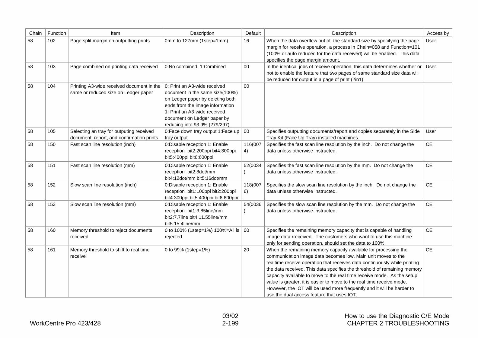
03/02 How to use the Diagnostic C/E ModeWorkCentre Pro 423/428 2-199 CHAPTER 2 TROUBLESHOOTING
Chain Function Item Description Default Description Access by
58 102 Page split margin on outputting prints 0mm to 127mm (1step=1mm) 16 When the data overflew out of the standard size by specifying the pagemargin for receive operation, a process in Chain=058 and Function=101(100% or auto reduced for the data received) will be enabled. This dataspecifies the page margin amount.
User
58 103 Page combined on printing data received 0:No combined 1:Combined 00 In the identical jobs of receive operation, this data determines whether ornot to enable the feature that two pages of same standard size data willbe reduced for output in a page of print (2in1).
User
58 104 Printing A3-wide received document in thesame or reduced size on Ledger paper
0: Print an A3-wide receiveddocument in the same size(100%)on Ledger paper by deleting bothends from the image information1: Print an A3-wide receiveddocument on Ledger paper byreducing into 93.9% (279/297).
00
58 105 Selecting an tray for outputing receiveddocument, report, and confirmation prints
0:Face down tray output 1:Face uptray output
00 Specifies outputting documents/report and copies separately in the SideTray Kit (Face Up Tray) installed machines.
User
58 150 Fast scan line resolution (inch) 0:Disable reception 1: Enablereception bit2:200ppi bit4:300ppibit5:400ppi bit6:600ppi
116(0074)
Specifies the fast scan line resolution by the inch. Do not change thedata unless otherwise instructed.
CE
58 151 Fast scan line resolution (mm) 0:Disable reception 1: Enablereception bit2:8dot/mmbit4:12dot/mm bit5:16dot/mm
52(0034)
Specifies the fast scan line resolution by the mm. Do not change thedata unless otherwise instructed.
CE
58 152 Slow scan line resolution (inch) 0:Disable reception 1: Enablereception bit1:100ppi bit2:200ppibit4:300ppi bit5:400ppi bit6:600ppi
118(0076)
Specifies the slow scan line resolution by the inch. Do not change thedata unless otherwise instructed.
CE
58 153 Slow scan line resolution (mm) 0:Disable reception 1: Enablereception bit1:3.85line/mmbit2:7.7line bit4:11.55line/mmbit5:15.4line/mm
54(0036)
Specifies the slow scan line resolution by the mm. Do not change thedata unless otherwise instructed.
CE
58 160 Memory threshold to reject documentsreceived
0 to 100% (1step=1%) 100%=All isrejected
00 Specifies the remaining memory capacity that is capable of handlingimage data rreceived. The customers who want to use this machineonly for sending operation, should set the data to 100%.
CE
58 161 Memory threshold to shift to real timereceive
0 to 99% (1step=1%) 20 When the remaining memory capacity available for processing thecommunication image data becomes low, Main unit moves to therealtime receive operation that receives data continuously while printingthe data received. This data specifies the threshold of remaining memorycapacity available to move to the real time receive mode. As the setupvalue is greater, it is easier to move to the real time receive mode.However, the IOT will be used more frequently and it will be harder touse the dual access feature that uses IOT.
CE
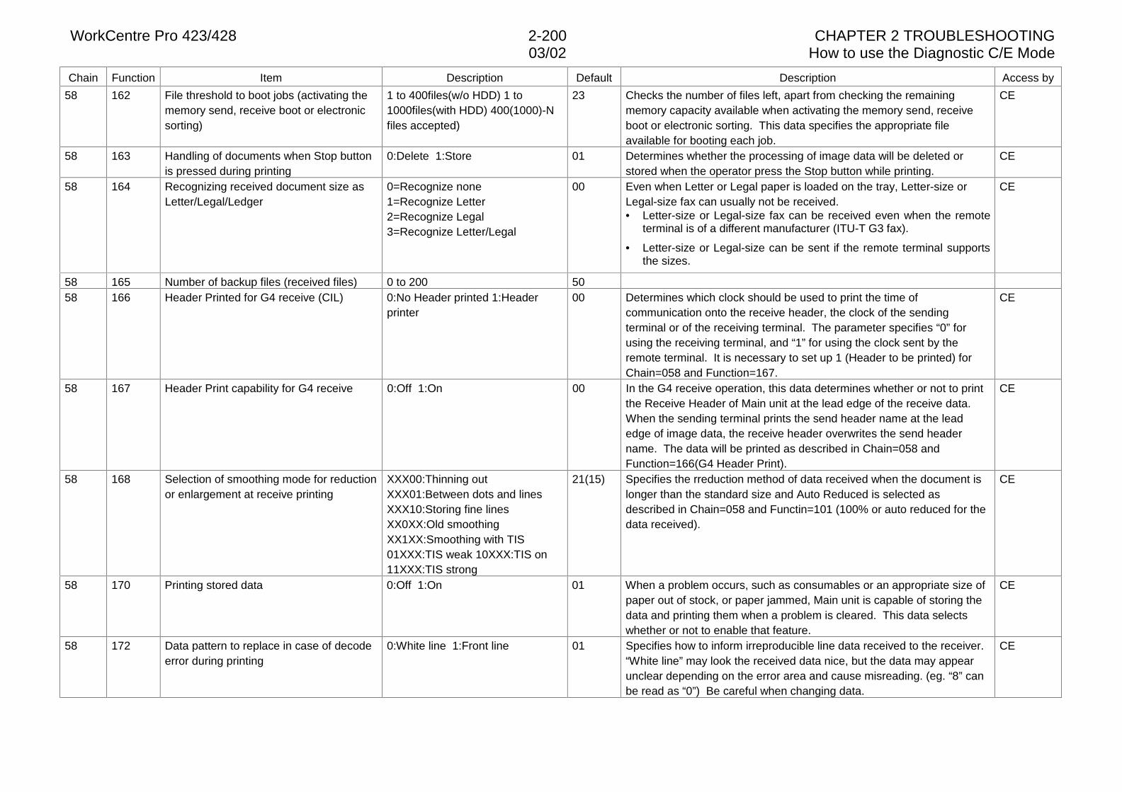
WorkCentre Pro 423/428 2-200 CHAPTER 2 TROUBLESHOOTING03/02 How to use the Diagnostic C/E Mode
Chain Function Item Description Default Description Access by
58 162 File threshold to boot jobs (activating thememory send, receive boot or electronicsorting)
1 to 400files(w/o HDD) 1 to1000files(with HDD) 400(1000)-Nfiles accepted)
23 Checks the number of files left, apart from checking the remainingmemory capacity available when activating the memory send, receiveboot or electronic sorting. This data specifies the appropriate fileavailable for booting each job.
CE
58 163 Handling of documents when Stop buttonis pressed during printing
0:Delete 1:Store 01 Determines whether the processing of image data will be deleted orstored when the operator press the Stop button while printing.
CE
58 164 Recognizing received document size asLetter/Legal/Ledger
0=Recognize none1=Recognize Letter2=Recognize Legal3=Recognize Letter/Legal
00 Even when Letter or Legal paper is loaded on the tray, Letter-size orLegal-size fax can usually not be received.• Letter-size or Legal-size fax can be received even when the remote
terminal is of a different manufacturer (ITU-T G3 fax).
• Letter-size or Legal-size can be sent if the remote terminal supportsthe sizes.
CE
58 165 Number of backup files (received files) 0 to 200 5058 166 Header Printed for G4 receive (CIL) 0:No Header printed 1:Header
printer00 Determines which clock should be used to print the time of
communication onto the receive header, the clock of the sendingterminal or of the receiving terminal. The parameter specifies “0” forusing the receiving terminal, and “1” for using the clock sent by theremote terminal. It is necessary to set up 1 (Header to be printed) forChain=058 and Function=167.
CE
58 167 Header Print capability for G4 receive 0:Off 1:On 00 In the G4 receive operation, this data determines whether or not to printthe Receive Header of Main unit at the lead edge of the receive data.When the sending terminal prints the send header name at the leadedge of image data, the receive header overwrites the send headername. The data will be printed as described in Chain=058 andFunction=166(G4 Header Print).
CE
58 168 Selection of smoothing mode for reductionor enlargement at receive printing
XXX00:Thinning outXXX01:Between dots and linesXXX10:Storing fine linesXX0XX:Old smoothingXX1XX:Smoothing with TIS01XXX:TIS weak 10XXX:TIS on11XXX:TIS strong
21(15) Specifies the rreduction method of data received when the document islonger than the standard size and Auto Reduced is selected asdescribed in Chain=058 and Functin=101 (100% or auto reduced for thedata received).
CE
58 170 Printing stored data 0:Off 1:On 01 When a problem occurs, such as consumables or an appropriate size ofpaper out of stock, or paper jammed, Main unit is capable of storing thedata and printing them when a problem is cleared. This data selectswhether or not to enable that feature.
CE
58 172 Data pattern to replace in case of decodeerror during printing
0:White line 1:Front line 01 Specifies how to inform irreproducible line data received to the receiver.“White line” may look the received data nice, but the data may appearunclear depending on the error area and cause misreading. (eg. “8” canbe read as “0”) Be careful when changing data.
CE
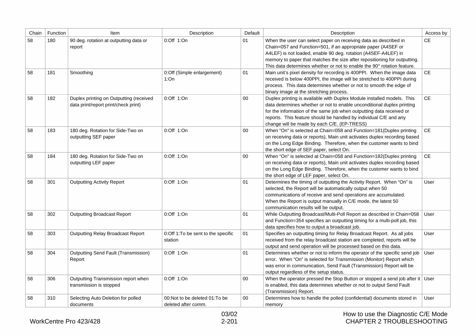
03/02 How to use the Diagnostic C/E ModeWorkCentre Pro 423/428 2-201 CHAPTER 2 TROUBLESHOOTING
Chain Function Item Description Default Description Access by
58 180 90 deg. rotation at outputting data orreport
0:Off 1:On 01 When the user can select paper on receiving data as described inChain=057 and Function=501, if an appropriate paper (A4SEF orA4LEF) is not loaded, enable 90 deg. rotation (A4SEF-A4LEF) inmemory to paper that matches the size after repositioning for outputting.This data determines whether or not to enable the 90° rotation feature.
CE
58 181 Smoothing 0:Off (Simple enlargement)1:On
01 Main unit’s pixel density for recording is 400PPI. When the image datareceived is below 400PPI, the image will be stretched to 400PPI duringprocess. This data determines whether or not to smooth the edge ofbinary image at the stretching process.
CE
58 182 Duplex printing on Outputting (receiveddata print/report print/check print)
0:Off 1:On 00 Duplex printing is available with Duplex Module installed models. Thisdata determines whether or not to enable unconditional duplex printingfor the information of the same job when outputting data received orreports. This feature should be handled by individual C/E and anychange will be made by each C/E. (EP-TRESS)
CE
58 183 180 deg. Rotation for Side-Two onoutputting SEF paper
0:Off 1:On 00 When “On” is selected at Chain=058 and Function=181(Duplex printingon receiving data or reports), Main unit activates duplex recording basedon the Long Edge Binding. Therefore, when the customer wants to bindthe short edge of SEF paper, select On.
CE
58 184 180 deg. Rotation for Side-Two onoutputting LEF paper
0:Off 1:On 00 When “On” is selected at Chain=058 and Function=182(Duplex printingon receiving data or reports), Main unit activates duplex recording basedon the Long Edge Binding. Therefore, when the customer wants to bindthe short edge of LEF paper, select On.
CE
58 301 Outputting Activity Report 0:Off 1:On 01 Determines the timing of outputting the Activity Report. When “On” isselected, the Report will be automatically output when 50communications of receive and send operations are accumulated.When the Report is output manually in C/E mode, the latest 50communication results will be output.
User
58 302 Outputting Broadcast Report 0:Off 1:On 01 While Outputting Broadcast/Multi-Poll Report as described in Chain=058and Function=354 specifies an outputting timing for a multi-poll job, thisdata specifies how to output a broadcast job.
User
58 303 Outputting Relay Broadcast Report 0:Off 1:To be sent to the specificstation
01 Specifies an outputting timing for Relay Broadcast Report. As all jobsreceived from the relay broadcast station are completed, reports will beoutput and send operation will be processed based on this data.
User
58 304 Outputting Send Fault (Transmission)Report
0:Off 1:On 01 Determines whether or not to inform the operator of the specific send joberror. When “On” is selected for Transmission (Monitor) Report whichwas error in communication, Send Fault (Transmission) Report will beoutput regardless of the setup status.
User
58 306 Outputting Transmission report whentransmission is stopped
0:Off 1:On 00 When the operator pressed the Stop Button or stopped a send job after itis enabled, this data determines whether or not to output Send Fault(Transmission) Report.
User
58 310 Selecting Auto Deletion for polleddocuments
00:Not to be deleted 01:To bedeleted after comm.
00 Determines how to handle the polled (confidential) documents stored inmemory
User
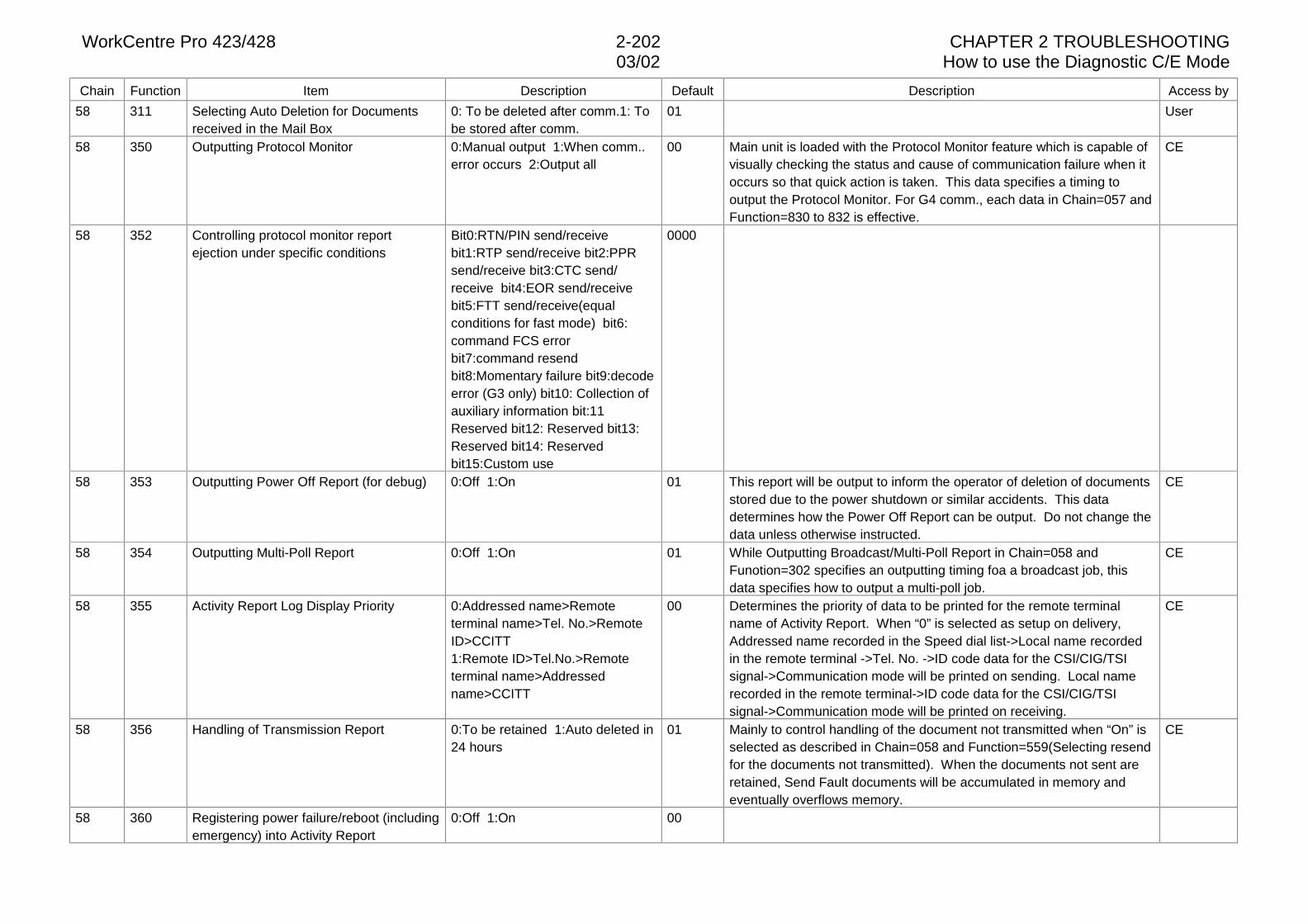
WorkCentre Pro 423/428 2-202 CHAPTER 2 TROUBLESHOOTING03/02 How to use the Diagnostic C/E Mode
Chain Function Item Description Default Description Access by
58 311 Selecting Auto Deletion for Documentsreceived in the Mail Box
0: To be deleted after comm.1: Tobe stored after comm.
01 User
58 350 Outputting Protocol Monitor 0:Manual output 1:When comm..error occurs 2:Output all
00 Main unit is loaded with the Protocol Monitor feature which is capable ofvisually checking the status and cause of communication failure when itoccurs so that quick action is taken. This data specifies a timing tooutput the Protocol Monitor. For G4 comm., each data in Chain=057 andFunction=830 to 832 is effective.
CE
58 352 Controlling protocol monitor reportejection under specific conditions
Bit0:RTN/PIN send/receivebit1:RTP send/receive bit2:PPRsend/receive bit3:CTC send/receive bit4:EOR send/receivebit5:FTT send/receive(equalconditions for fast mode) bit6:command FCS errorbit7:command resendbit8:Momentary failure bit9:decodeerror (G3 only) bit10: Collection ofauxiliary information bit:11Reserved bit12: Reserved bit13:Reserved bit14: Reservedbit15:Custom use
0000
58 353 Outputting Power Off Report (for debug) 0:Off 1:On 01 This report will be output to inform the operator of deletion of documentsstored due to the power shutdown or similar accidents. This datadetermines how the Power Off Report can be output. Do not change thedata unless otherwise instructed.
CE
58 354 Outputting Multi-Poll Report 0:Off 1:On 01 While Outputting Broadcast/Multi-Poll Report in Chain=058 andFunotion=302 specifies an outputting timing foa a broadcast job, thisdata specifies how to output a multi-poll job.
CE
58 355 Activity Report Log Display Priority 0:Addressed name>Remoteterminal name>Tel. No.>RemoteID>CCITT1:Remote ID>Tel.No.>Remoteterminal name>Addressedname>CCITT
00 Determines the priority of data to be printed for the remote terminalname of Activity Report. When “0” is selected as setup on delivery,Addressed name recorded in the Speed dial list->Local name recordedin the remote terminal ->Tel. No. ->ID code data for the CSI/CIG/TSIsignal->Communication mode will be printed on sending. Local namerecorded in the remote terminal->ID code data for the CSI/CIG/TSIsignal->Communication mode will be printed on receiving.
CE
58 356 Handling of Transmission Report 0:To be retained 1:Auto deleted in24 hours
01 Mainly to control handling of the document not transmitted when “On” isselected as described in Chain=058 and Function=559(Selecting resendfor the documents not transmitted). When the documents not sent areretained, Send Fault documents will be accumulated in memory andeventually overflows memory.
CE
58 360 Registering power failure/reboot (includingemergency) into Activity Report
0:Off 1:On 00
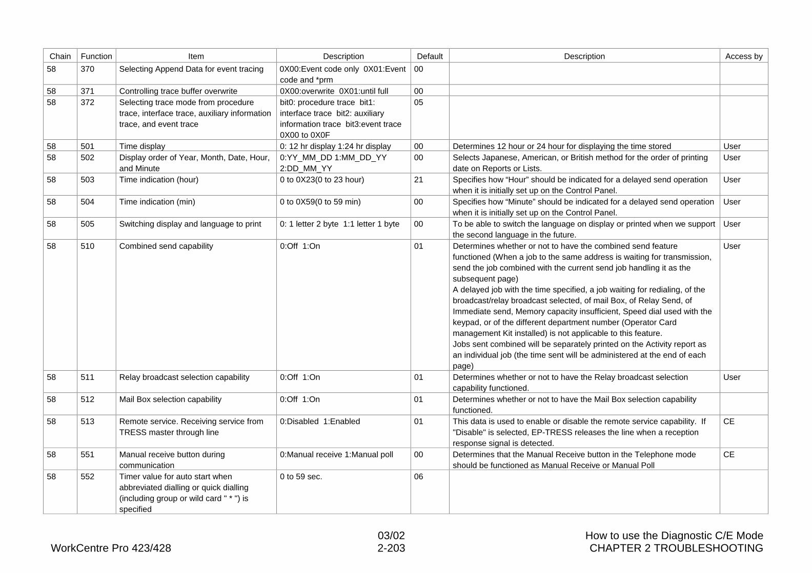
03/02 How to use the Diagnostic C/E ModeWorkCentre Pro 423/428 2-203 CHAPTER 2 TROUBLESHOOTING
Chain Function Item Description Default Description Access by
58 370 Selecting Append Data for event tracing 0X00:Event code only 0X01:Eventcode and *prm
00
58 371 Controlling trace buffer overwrite 0X00:overwrite 0X01:until full 0058 372 Selecting trace mode from procedure
trace, interface trace, auxiliary informationtrace, and event trace
bit0: procedure trace bit1:interface trace bit2: auxiliaryinformation trace bit3:event trace0X00 to 0X0F
05
58 501 Time display 0: 12 hr display 1:24 hr display 00 Determines 12 hour or 24 hour for displaying the time stored User58 502 Display order of Year, Month, Date, Hour,
and Minute0:YY_MM_DD 1:MM_DD_YY2:DD_MM_YY
00 Selects Japanese, American, or British method for the order of printingdate on Reports or Lists.
User
58 503 Time indication (hour) 0 to 0X23(0 to 23 hour) 21 Specifies how “Hour” should be indicated for a delayed send operationwhen it is initially set up on the Control Panel.
User
58 504 Time indication (min) 0 to 0X59(0 to 59 min) 00 Specifies how “Minute” should be indicated for a delayed send operationwhen it is initially set up on the Control Panel.
User
58 505 Switching display and language to print 0: 1 letter 2 byte 1:1 letter 1 byte 00 To be able to switch the language on display or printed when we supportthe second language in the future.
User
58 510 Combined send capability 0:Off 1:On 01 Determines whether or not to have the combined send featurefunctioned (When a job to the same address is waiting for transmission,send the job combined with the current send job handling it as thesubsequent page)A delayed job with the time specified, a job waiting for redialing, of thebroadcast/relay broadcast selected, of mail Box, of Relay Send, ofImmediate send, Memory capacity insufficient, Speed dial used with thekeypad, or of the different department number (Operator Cardmanagement Kit installed) is not applicable to this feature.Jobs sent combined will be separately printed on the Activity report asan individual job (the time sent will be administered at the end of eachpage)
User
58 511 Relay broadcast selection capability 0:Off 1:On 01 Determines whether or not to have the Relay broadcast selectioncapability functioned.
User
58 512 Mail Box selection capability 0:Off 1:On 01 Determines whether or not to have the Mail Box selection capabilityfunctioned.
58 513 Remote service. Receiving service fromTRESS master through line
0:Disabled 1:Enabled 01 This data is used to enable or disable the remote service capability. If"Disable" is selected, EP-TRESS releases the line when a receptionresponse signal is detected.
CE
58 551 Manual receive button duringcommunication
0:Manual receive 1:Manual poll 00 Determines that the Manual Receive button in the Telephone modeshould be functioned as Manual Receive or Manual Poll
CE
58 552 Timer value for auto start whenabbreviated dialling or quick dialling(including group or wild card " * ") isspecified
0 to 59 sec. 06
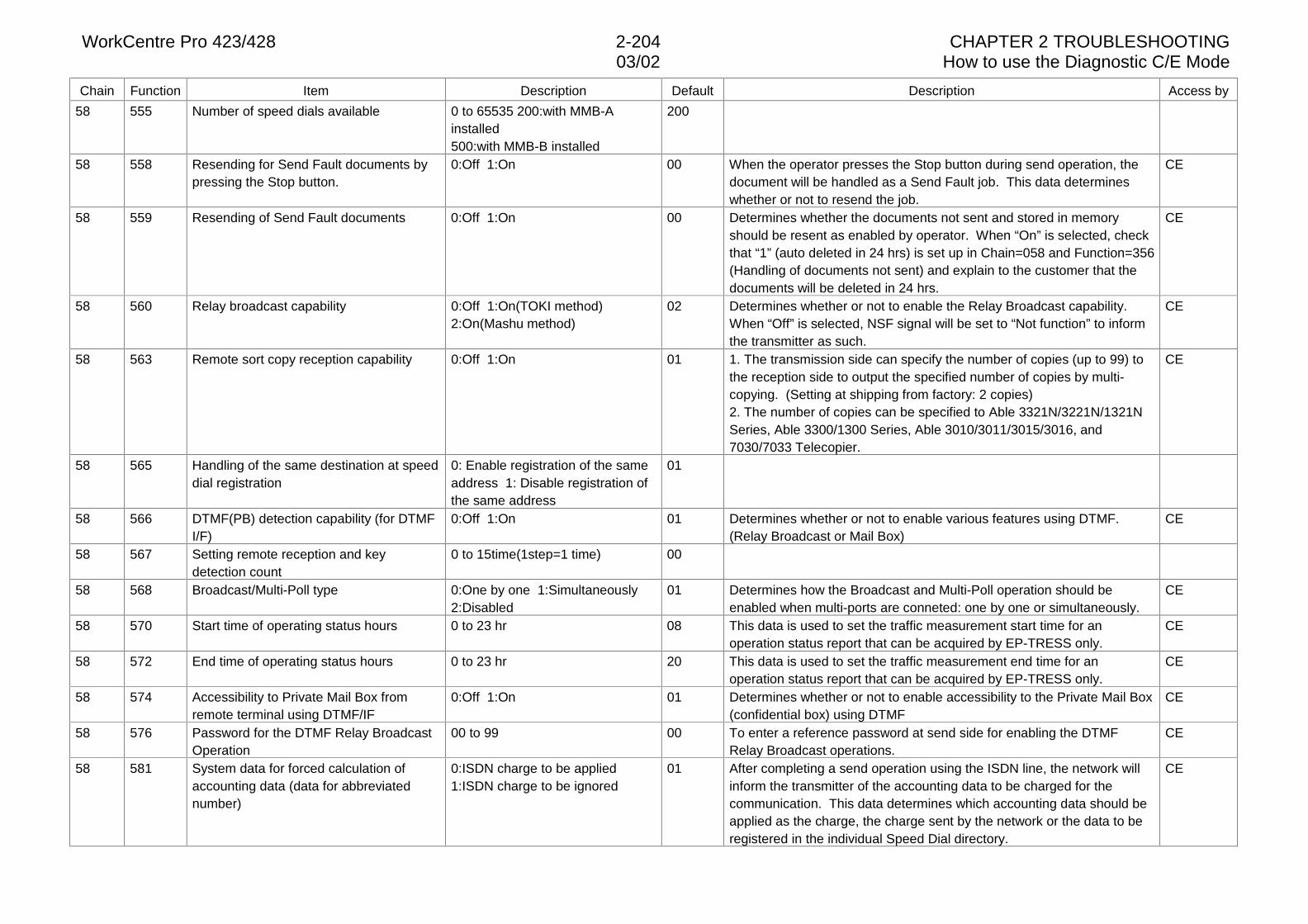
WorkCentre Pro 423/428 2-204 CHAPTER 2 TROUBLESHOOTING03/02 How to use the Diagnostic C/E Mode
Chain Function Item Description Default Description Access by
58 555 Number of speed dials available 0 to 65535 200:with MMB-Ainstalled500:with MMB-B installed
200
58 558 Resending for Send Fault documents bypressing the Stop button.
0:Off 1:On 00 When the operator presses the Stop button during send operation, thedocument will be handled as a Send Fault job. This data determineswhether or not to resend the job.
CE
58 559 Resending of Send Fault documents 0:Off 1:On 00 Determines whether the documents not sent and stored in memoryshould be resent as enabled by operator. When “On” is selected, checkthat “1” (auto deleted in 24 hrs) is set up in Chain=058 and Function=356(Handling of documents not sent) and explain to the customer that thedocuments will be deleted in 24 hrs.
CE
58 560 Relay broadcast capability 0:Off 1:On(TOKI method)2:On(Mashu method)
02 Determines whether or not to enable the Relay Broadcast capability.When “Off” is selected, NSF signal will be set to “Not function” to informthe transmitter as such.
CE
58 563 Remote sort copy reception capability 0:Off 1:On 01 1. The transmission side can specify the number of copies (up to 99) tothe reception side to output the specified number of copies by multi-copying. (Setting at shipping from factory: 2 copies)2. The number of copies can be specified to Able 3321N/3221N/1321NSeries, Able 3300/1300 Series, Able 3010/3011/3015/3016, and7030/7033 Telecopier.
CE
58 565 Handling of the same destination at speeddial registration
0: Enable registration of the sameaddress 1: Disable registration ofthe same address
01
58 566 DTMF(PB) detection capability (for DTMFI/F)
0:Off 1:On 01 Determines whether or not to enable various features using DTMF.(Relay Broadcast or Mail Box)
CE
58 567 Setting remote reception and keydetection count
0 to 15time(1step=1 time) 00
58 568 Broadcast/Multi-Poll type 0:One by one 1:Simultaneously2:Disabled
01 Determines how the Broadcast and Multi-Poll operation should beenabled when multi-ports are conneted: one by one or simultaneously.
CE
58 570 Start time of operating status hours 0 to 23 hr 08 This data is used to set the traffic measurement start time for anoperation status report that can be acquired by EP-TRESS only.
CE
58 572 End time of operating status hours 0 to 23 hr 20 This data is used to set the traffic measurement end time for anoperation status report that can be acquired by EP-TRESS only.
CE
58 574 Accessibility to Private Mail Box fromremote terminal using DTMF/IF
0:Off 1:On 01 Determines whether or not to enable accessibility to the Private Mail Box(confidential box) using DTMF
CE
58 576 Password for the DTMF Relay BroadcastOperation
00 to 99 00 To enter a reference password at send side for enabling the DTMFRelay Broadcast operations.
CE
58 581 System data for forced calculation ofaccounting data (data for abbreviatednumber)
0:ISDN charge to be applied1:ISDN charge to be ignored
01 After completing a send operation using the ISDN line, the network willinform the transmitter of the accounting data to be charged for thecommunication. This data determines which accounting data should beapplied as the charge, the charge sent by the network or the data to beregistered in the individual Speed Dial directory.
CE
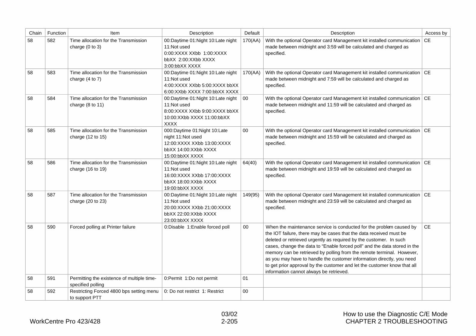
03/02 How to use the Diagnostic C/E ModeWorkCentre Pro 423/428 2-205 CHAPTER 2 TROUBLESHOOTING
Chain Function Item Description Default Description Access by
58 582 Time allocation for the Transmissioncharge (0 to 3)
00:Daytime 01:Night 10:Late night11:Not used0:00:XXXX XXbb 1:00:XXXXbbXX 2:00:XXbb XXXX3:00:bbXX XXXX
170(AA) With the optional Operator card Management kit installed communicationmade between midnight and 3:59 will be calculated and charged asspecified.
CE
58 583 Time allocation for the Transmissioncharge (4 to 7)
00:Daytime 01:Night 10:Late night11:Not used4:00:XXXX XXbb 5:00:XXXX bbXX6:00:XXbb XXXX 7:00:bbXX XXXX
170(AA) With the optional Operator card Management kit installed communicationmade between midnight and 7:59 will be calculated and charged asspecified.
CE
58 584 Time allocation for the Transmissioncharge (8 to 11)
00:Daytime 01:Night 10:Late night11:Not used8:00:XXXX XXbb 9:00:XXXX bbXX10:00:XXbb XXXX 11:00:bbXXXXXX
00 With the optional Operator card Management kit installed communicationmade between midnight and 11:59 will be calculated and charged asspecified.
CE
58 585 Time allocation for the Transmissioncharge (12 to 15)
000:Daytime 01:Night 10:Latenight 11:Not used12:00:XXXX XXbb 13:00:XXXXbbXX 14:00:XXbb XXXX15:00:bbXX XXXX
00 With the optional Operator card Management kit installed communicationmade between midnight and 15:59 will be calculated and charged asspecified.
CE
58 586 Time allocation for the Transmissioncharge (16 to 19)
00:Daytime 01:Night 10:Late night11:Not used16:00:XXXX XXbb 17:00:XXXXbbXX 18:00:XXbb XXXX19:00:bbXX XXXX
64(40) With the optional Operator card Management kit installed communicationmade between midnight and 19:59 will be calculated and charged asspecified.
CE
58 587 Time allocation for the Transmissioncharge (20 to 23)
00:Daytime 01:Night 10:Late night11:Not used20:00:XXXX XXbb 21:00:XXXXbbXX 22:00:XXbb XXXX23:00:bbXX XXXX
149(95) With the optional Operator card Management kit installed communicationmade between midnight and 23:59 will be calculated and charged asspecified.
CE
58 590 Forced polling at Printer failure 0:Disable 1:Enable forced poll 00 When the maintenance service is conducted for the problem caused bythe IOT failure, there may be cases that the data received must bedeleted or retrieved urgently as required by the customer. In suchcases, change the data to “Enable forced poll” and the data stored in thememory can be retrieved by polling from the remote terminal. However,as you may have to handle the customer information directly, you needto get prior approval by the customer and let the customer know that allinformation cannot always be retrieved.
CE
58 591 Permitting the existence of multiple time-specified polling
0:Permit 1:Do not permit 01
58 592 Restricting Forced 4800 bps setting menuto support PTT
0: Do not restrict 1: Restrict 00
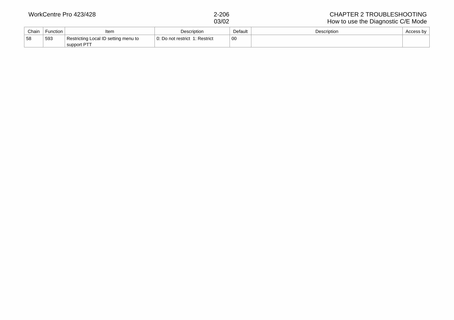
WorkCentre Pro 423/428 2-206 CHAPTER 2 TROUBLESHOOTING03/02 How to use the Diagnostic C/E Mode
Chain Function Item Description Default Description Access by
58 593 Restricting Local ID setting menu tosupport PTT
0: Do not restrict 1: Restrict 00
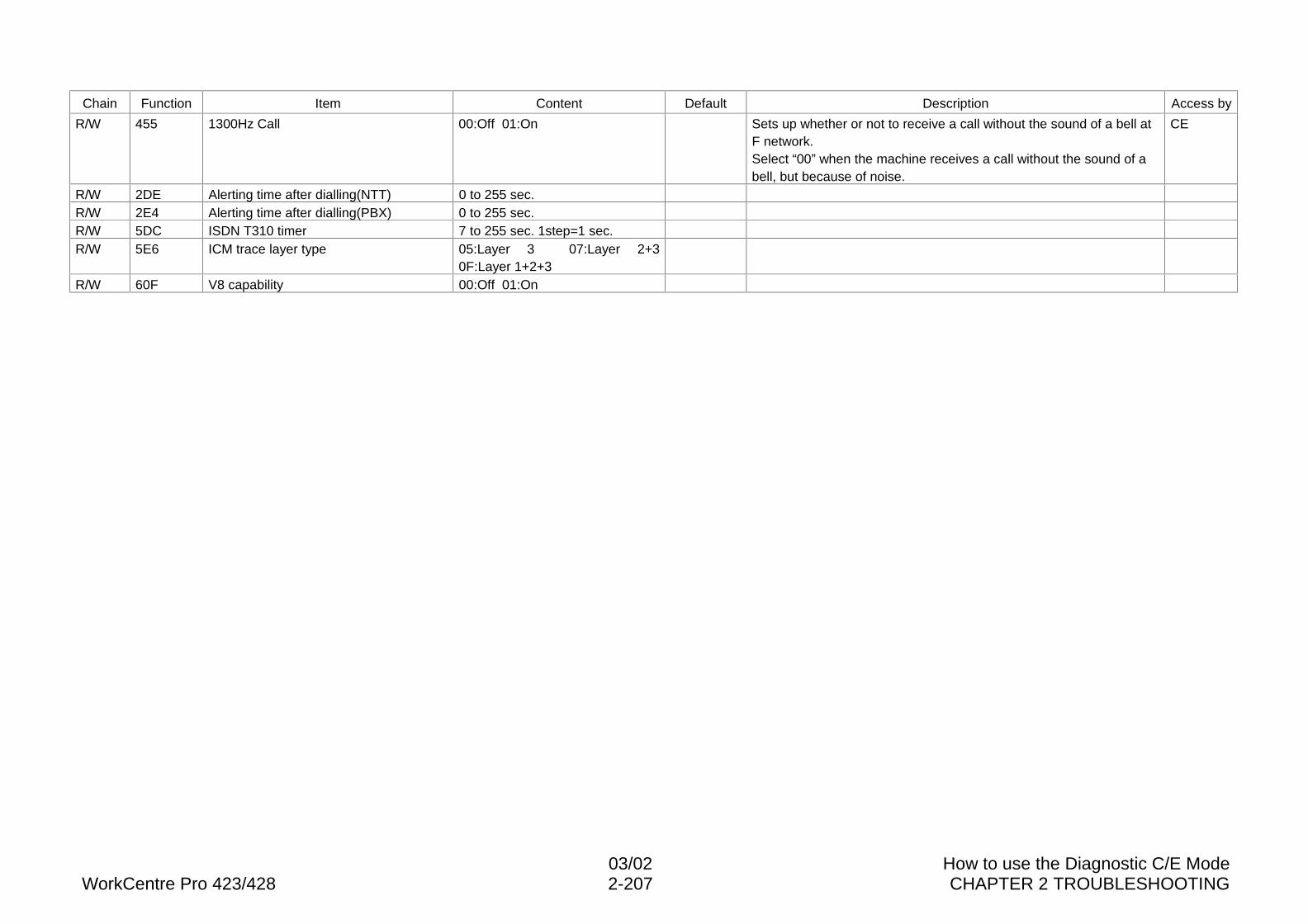
03/02 How to use the Diagnostic C/E ModeWorkCentre Pro 423/428 2-207 CHAPTER 2 TROUBLESHOOTING
Chain Function Item Content Default Description Access by
R/W 455 1300Hz Call 00:Off 01:On Sets up whether or not to receive a call without the sound of a bell atF network.Select “00” when the machine receives a call without the sound of abell, but because of noise.
CE
R/W 2DE Alerting time after dialling(NTT) 0 to 255 sec.R/W 2E4 Alerting time after dialling(PBX) 0 to 255 sec.R/W 5DC ISDN T310 timer 7 to 255 sec. 1step=1 sec.R/W 5E6 ICM trace layer type 05:Layer 3 07:Layer 2+3
0F:Layer 1+2+3R/W 60F V8 capability 00:Off 01:On
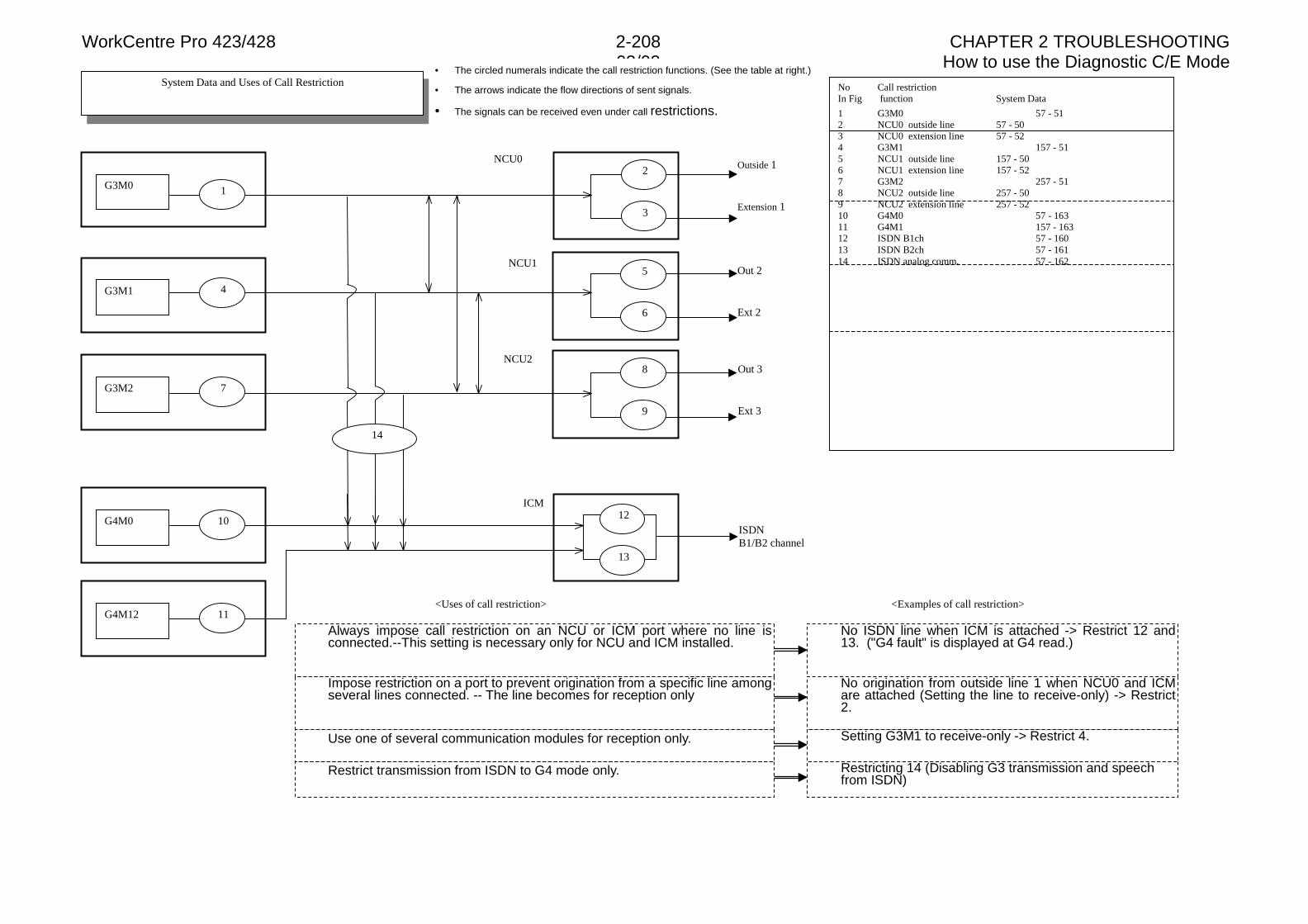
WorkCentre Pro 423/428 2-208 CHAPTER 2 TROUBLESHOOTING03/02 How to use the Diagnostic C/E Mode
<Uses of call restriction> <Examples of call restriction>
NCU2
NCU0
NCU1
ICM
System Data and Uses of Call Restriction
G3M0
G3M1
G3M2
G4M0
G4M12 11
13
12
14
10
3
2
Extension 1
Outside 1
6
5
Ext 2
Out 2
8
9 Ext 3
Out 3
ISDNB1/B2 channel
No Call restrictionIn Fig function System Data
1 G3M0 57 - 512 NCU0 outside line 57 - 503 NCU0 extension line 57 - 524 G3M1 157 - 515 NCU1 outside line 157 - 506 NCU1 extension line 157 - 527 G3M2 257 - 518 NCU2 outside line 257 - 509 NCU2 extension line 257 - 5210 G4M0 57 - 16311 G4M1 157 - 16312 ISDN B1ch 57 - 16013 ISDN B2ch 57 - 16114 ISDN analog comm. 57 - 162
• The circled numerals indicate the call restriction functions. (See the table at right.)
• The arrows indicate the flow directions of sent signals.
• The signals can be received even under call restrictions.
Impose restriction on a port to prevent origination from a specific line amongseveral lines connected. -- The line becomes for reception only
Restrict transmission from ISDN to G4 mode only.
Always impose call restriction on an NCU or ICM port where no line isconnected.--This setting is necessary only for NCU and ICM installed.
No ISDN line when ICM is attached -> Restrict 12 and13. ("G4 fault" is displayed at G4 read.)
Use one of several communication modules for reception only.
Restricting 14 (Disabling G3 transmission and speechfrom ISDN)
No origination from outside line 1 when NCU0 and ICMare attached (Setting the line to receive-only) -> Restrict2.
Setting G3M1 to receive-only -> Restrict 4.
7
4
1
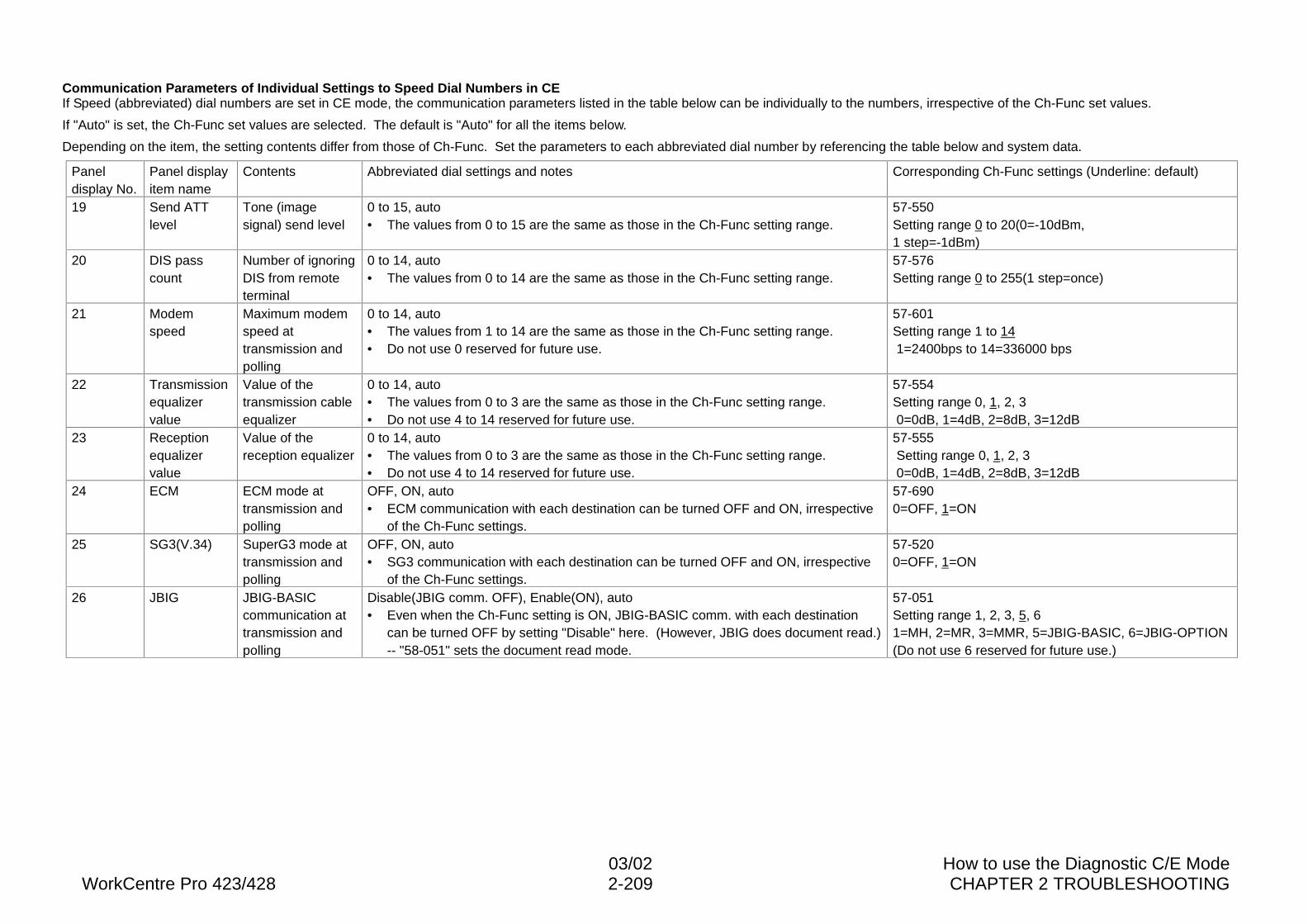
03/02 How to use the Diagnostic C/E ModeWorkCentre Pro 423/428 2-209 CHAPTER 2 TROUBLESHOOTING
Communication Parameters of Individual Settings to Speed Dial Numbers in CEIf Speed (abbreviated) dial numbers are set in CE mode, the communication parameters listed in the table below can be individually to the numbers, irrespective of the Ch-Func set values.
If "Auto" is set, the Ch-Func set values are selected. The default is "Auto" for all the items below.
Depending on the item, the setting contents differ from those of Ch-Func. Set the parameters to each abbreviated dial number by referencing the table below and system data.
Paneldisplay No.
Panel displayitem name
Contents Abbreviated dial settings and notes Corresponding Ch-Func settings (Underline: default)
19 Send ATTlevel
Tone (imagesignal) send level
0 to 15, auto• The values from 0 to 15 are the same as those in the Ch-Func setting range.
57-550Setting range 0 to 20(0=-10dBm,1 step=-1dBm)
20 DIS passcount
Number of ignoringDIS from remoteterminal
0 to 14, auto• The values from 0 to 14 are the same as those in the Ch-Func setting range.
57-576Setting range 0 to 255(1 step=once)
21 Modemspeed
Maximum modemspeed attransmission andpolling
0 to 14, auto• The values from 1 to 14 are the same as those in the Ch-Func setting range.• Do not use 0 reserved for future use.
57-601Setting range 1 to 14 1=2400bps to 14=336000 bps
22 Transmissionequalizervalue
Value of thetransmission cableequalizer
0 to 14, auto• The values from 0 to 3 are the same as those in the Ch-Func setting range.• Do not use 4 to 14 reserved for future use.
57-554Setting range 0, 1, 2, 3 0=0dB, 1=4dB, 2=8dB, 3=12dB
23 Receptionequalizervalue
Value of thereception equalizer
0 to 14, auto• The values from 0 to 3 are the same as those in the Ch-Func setting range.• Do not use 4 to 14 reserved for future use.
57-555 Setting range 0, 1, 2, 3 0=0dB, 1=4dB, 2=8dB, 3=12dB
24 ECM ECM mode attransmission andpolling
OFF, ON, auto• ECM communication with each destination can be turned OFF and ON, irrespective
of the Ch-Func settings.
57-6900=OFF, 1=ON
25 SG3(V.34) SuperG3 mode attransmission andpolling
OFF, ON, auto• SG3 communication with each destination can be turned OFF and ON, irrespective
of the Ch-Func settings.
57-5200=OFF, 1=ON
26 JBIG JBIG-BASICcommunication attransmission andpolling
Disable(JBIG comm. OFF), Enable(ON), auto• Even when the Ch-Func setting is ON, JBIG-BASIC comm. with each destination
can be turned OFF by setting "Disable" here. (However, JBIG does document read.)-- "58-051" sets the document read mode.
57-051Setting range 1, 2, 3, 5, 61=MH, 2=MR, 3=MMR, 5=JBIG-BASIC, 6=JBIG-OPTION(Do not use 6 reserved for future use.)
WorkCentre Pro 423/428 2-210 CHAPTER 2 TROUBLESHOOTING03/02 How to use the Diagnostic C/E Mode

CHAPTER 3 IMAGE QUALITY TROUBLESHOOTING

03/02 ContentsWorkCentre Pro 423/428 3-1 CHAPTER 3 IMAGE QUALITY TROUBLESHOOTING
Contents
3.1 Introduction............................................................................................2
3.1.1 Chapter 3 Composition and Distinction...............................................................23.1.2 How to Use the Image Troubleshooting ..............................................................2
3.2 Image Quality Specifications..................................................................3
3.2.1 Test Pattern Types ..............................................................................................33.2.2 How to Use the Test Pattern ...............................................................................33.2.3 Built-in Test Pattern .............................................................................................6
3.3 Image Quality Troubleshooting ..............................................................9
3.3.1 Copy Sample ......................................................................................................93.3.2 Cautions on image quality troubleshooting .........................................................93.3.3 Basic rules on action against image quality problems.........................................93.3.4 Image Quality Adjustment ...................................................................................93.3.5 Corrective action against image quality problems............................................. 11
C - 1 Too light copies ............................................................................................... 11C - 2 White copies ...................................................................................................12C - 3 White off: Copy sample ...................................................................................13C - 4 White off: Copy sample ...................................................................................13C - 5 White off Copy sample ....................................................................................14C - 6 Spot white off Copy sample.............................................................................15C - 7 Black lines Copy sample .................................................................................15C - 8 Black lines Copy sample .................................................................................16C - 9 Black spots Copy sample................................................................................16C - 10 Belt high-background Copy sample .............................................................17C - 11 Belt high-background Copy sample .............................................................17C - 12 High background Copy sample ....................................................................18C - 13 Solid black copies ........................................................................................18C - 14 Skip..............................................................................................................19C - 15 Smear Copy sample ....................................................................................20C - 16 Jitter/Data error Copy sample ......................................................................20C - 17 Distortion (Hunting) Copy sample ................................................................21C - 18 Banding Copy sample..................................................................................21C - 19 Magnification failure Copy sample ...............................................................22C - 20 Poor resolution.............................................................................................22C - 21 Residual image (ghost) ................................................................................23C - 22 Finger Mark..................................................................................................23C - 23 Moiré............................................................................................................24C - 24 Poor fusing...................................................................................................24C - 25 Poor registration: Copy sample....................................................................25C - 26 Uneven density: Copy sample .....................................................................26C - 27 Wrinkle in copies..........................................................................................26
C - 28 Skew............................................................................................................ 27C - 29 Black bands................................................................................................. 28C - 30 Dark copies.................................................................................................. 28
WorkCentre Pro 423/428 3-2 CHAPTER 3 IMAGE QUALITY TROUBLESHOOTING3.1 Introduction
3.1 Introduction
3.1.1 Chapter 3 Composition and Distinction
1. Chapter 3, Image Quality Troubleshooting, is subdivided into Image QualitySpecifications and Image Quality Troubleshooting.
2. In the Image Quality Specification section, all types of test patterns and image qualityjudgment procedures using and applications of test patterns are explained.
3. In the Image Quality Troubleshooting section, troubleshooting procedures of possibleimage quality problems and components causing image quality problems are explained.Procedures are described in tables, which contain problem causes and corrective actionprocedures.
3.1.2 How to Use the Image Troubleshooting
1. Select a page corresponding to the image quality troubleshooting to be executed fromthe Contents and following the corrective action procedure instructed therein.
2. Always use the correct judgment procedure when an image quality problem is analyzed,referring to 3.2 Image Quality Specifications.
3. For image quality problems unique to the fax mode, check if the same problem recursby making test communications with the NSC. If the problem does not recur, ask theremote terminal operator to check for abnormalities.
3.2 Image Quality SpecificationsWorkCentre Pro 423/428 3-3 CHAPTER 3 IMAGE QUALITY TROUBLESHOOTING
3.2 Image Quality Specifications
3.2.1 Test Pattern Types
The following three types of Test Patterns are used for DocuCentre 230/280:l 499T247 A3 Test Pattern (Fig.1)l 499T281 Fax Test Pattern (Fig.2)l Built-in Test Pattern (This Test Pattern is stored in the memory and used for identifying
problem causes for boards)
3.2.2 How to Use the Test Pattern
Note For specifications, refer to Section 6 Specifications.
To check copy quality, use A3 Test Pattern (499T247). For checking image quality whenthe DADF is used or send/receive using fax features, use fax Test Pattern (499T281). FaxTest Pattern (499T281) is a chart having A4 LEF and B4 SEF lead edges and is usedaccording to the document size. Use the ordinary paper for checking image quality.
A. MagnificationTerminology description
Indicates the vertical and horizontal enlargement or reduction percentages againstthe original. Matching to the selected magnification is specified.
Judgment procedure:l 499T247
Compare distance between two target positions on a copy to that on the TestPattern.
l 499T281Make a copy using the DADF and compare distance between two target positionson a copy to that on the Test Pattern.
B. Skip and SmearTerminology description:
Represents missing images in the copy feed and transverse directions. Degree ofmissing images is specified.
Judgment procedure:Make a copy of Test Pattern (499T247) and observe the ladder.
C. ResolutionTerminology description:
Represents how fine the original images can be reproduced and the degree isspecified. Resolution 4.3 indicates that each line is reproduced independentlywhen 4.3 lines are drawn within 1 mm at equal intervals.
Judgment procedure:Make a copy of Test Pattern (499T247) and observe resolution at three target areas(or two targets for enlarged copies).
D. LegibilityTerminology description:
The character reproducing level of a document send/received using the fax featureis specified.
Judgment procedure:Conduct send/receive using Test Pattern (499T281) and observe character patternsat two areas.
WorkCentre Pro 423/428 3-4 CHAPTER 3 IMAGE QUALITY TROUBLESHOOTING3.2 Image Quality Specifications
E. Lead Edge RegistrationTerminology description:
Represents deviation between lead edges of copy images and paper. The degreeof deviation is specified.
Judgment procedure:l 499T247
Measure distance from the lead edge of paper to that of images.l 499T281
Make a copy using the DADF and measure distance from the lead edge of paper tothe bottom line of an isosceles triangle.
F. Side RegistrationTerminology description:
Represents deviation of images in the copy feed direction and transverse to thecopy feed direction. The degree of image deviation is specified.
Judgment procedure:l 499T247
Measure distances between targets and side edges of the copy.l 499T281
Make a copy using the DADF and measure distance from the side edge of paper tothe bottom line of an isosceles triangle.
G. SkewTerminology description:
Indicates that copy images are copied at an angle against the paper. The degree ofinclination is specified.
Judgment procedure:l 499T247
Measure distances from two targets to the side edge of paper and calculate thedifference.
l 499T281Make a copy using the DADF and measure distance from the side edge of paper tothe bottom line of an isosceles triangle.
H. Line Copy DensityTerminology description:
Represents density of characters and lines. Degree of character and line density isspecified.
Judgment procedure:Make a copy of Test Pattern (499T281) and check density and uniformity at threeparagraphs.
I. Solid ReproducibilityTerminology description:
Represents image density of solid black area. Degree of solid image density isspecified.
Judgment procedure:l 499T247
Observe density and uniformity at three solid areas.l 499T281
Print the Test Pattern using the fax send/receive features and observe density anduniformity at three solid/white alternate areas.
White area: BackgroundTerminology description:
Represents density of areas without images. Degree of whiteness is specified.The work of high background is generally used to indicate dark white area orbackground.
Judgment procedure:Make a copy of Test Pattern (499T247) and observe the background which is thedarkest among white areas.
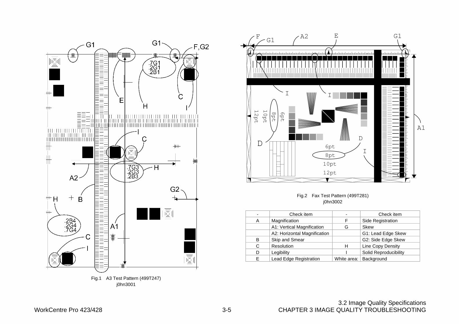
3.2 Image Quality SpecificationsWorkCentre Pro 423/428 3-5 CHAPTER 3 IMAGE QUALITY TROUBLESHOOTING
Fig.1 A3 Test Pattern (499T247)j0hn3001
D
G1EG1
F
II
A1
A2
I
D6pt
8pt
12pt
10pt
6pt
8pt
12pt
10pt
Fig.2 Fax Test Pattern (499T281)j0hn3002
- Check item - Check itemA Magnification F Side Registration
A1: Vertical Magnification G SkewA2: Horizontal Magnification G1: Lead Edge Skew
B Skip and Smear G2: Side Edge SkewC Resolution H Line Copy DensityD Legibility I Solid ReproducibilityE Lead Edge Registration White area: Background
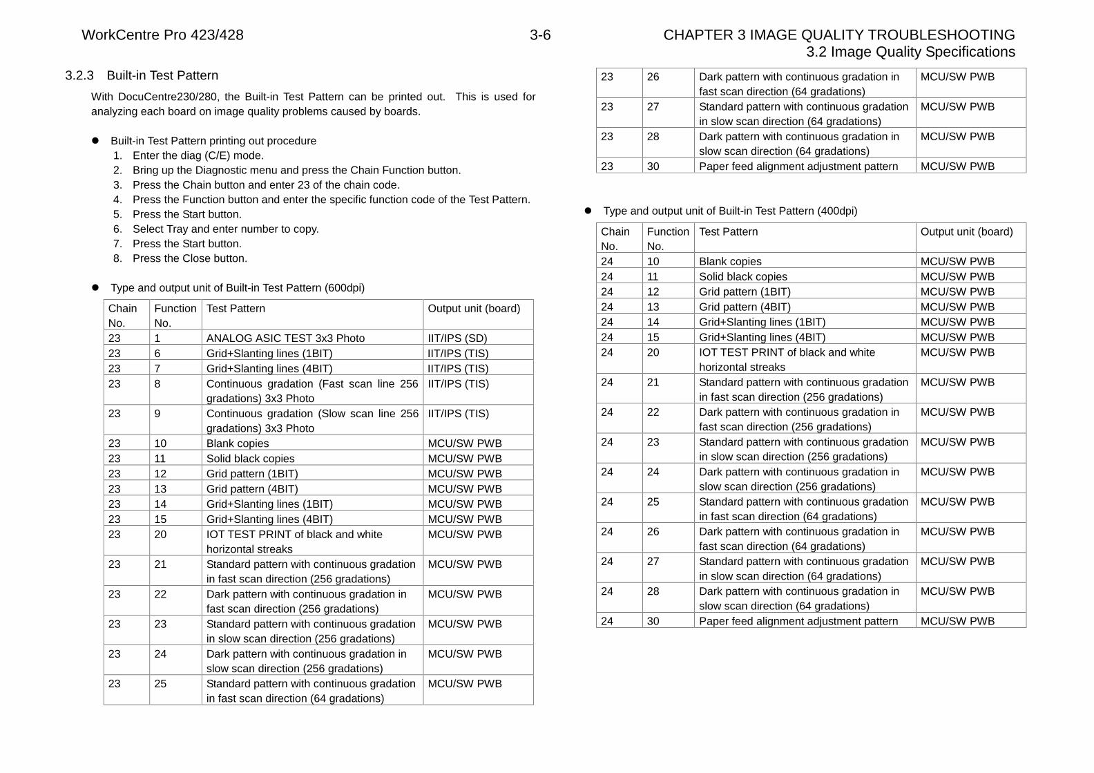
WorkCentre Pro 423/428 3-6 CHAPTER 3 IMAGE QUALITY TROUBLESHOOTING3.2 Image Quality Specifications
3.2.3 Built-in Test Pattern
With DocuCentre230/280, the Built-in Test Pattern can be printed out. This is used foranalyzing each board on image quality problems caused by boards.
l Built-in Test Pattern printing out procedure1. Enter the diag (C/E) mode.2. Bring up the Diagnostic menu and press the Chain Function button.3. Press the Chain button and enter 23 of the chain code.4. Press the Function button and enter the specific function code of the Test Pattern.5. Press the Start button.6. Select Tray and enter number to copy.7. Press the Start button.8. Press the Close button.
l Type and output unit of Built-in Test Pattern (600dpi)
ChainNo.
FunctionNo.
Test Pattern Output unit (board)
23 1 ANALOG ASIC TEST 3x3 Photo IIT/IPS (SD)23 6 Grid+Slanting lines (1BIT) IIT/IPS (TIS)23 7 Grid+Slanting lines (4BIT) IIT/IPS (TIS)23 8 Continuous gradation (Fast scan line 256
gradations) 3x3 PhotoIIT/IPS (TIS)
23 9 Continuous gradation (Slow scan line 256gradations) 3x3 Photo
IIT/IPS (TIS)
23 10 Blank copies MCU/SW PWB23 11 Solid black copies MCU/SW PWB23 12 Grid pattern (1BIT) MCU/SW PWB23 13 Grid pattern (4BIT) MCU/SW PWB23 14 Grid+Slanting lines (1BIT) MCU/SW PWB23 15 Grid+Slanting lines (4BIT) MCU/SW PWB23 20 IOT TEST PRINT of black and white
horizontal streaksMCU/SW PWB
23 21 Standard pattern with continuous gradationin fast scan direction (256 gradations)
MCU/SW PWB
23 22 Dark pattern with continuous gradation infast scan direction (256 gradations)
MCU/SW PWB
23 23 Standard pattern with continuous gradationin slow scan direction (256 gradations)
MCU/SW PWB
23 24 Dark pattern with continuous gradation inslow scan direction (256 gradations)
MCU/SW PWB
23 25 Standard pattern with continuous gradationin fast scan direction (64 gradations)
MCU/SW PWB
23 26 Dark pattern with continuous gradation infast scan direction (64 gradations)
MCU/SW PWB
23 27 Standard pattern with continuous gradationin slow scan direction (64 gradations)
MCU/SW PWB
23 28 Dark pattern with continuous gradation inslow scan direction (64 gradations)
MCU/SW PWB
23 30 Paper feed alignment adjustment pattern MCU/SW PWB
l Type and output unit of Built-in Test Pattern (400dpi)
ChainNo.
FunctionNo.
Test Pattern Output unit (board)
24 10 Blank copies MCU/SW PWB24 11 Solid black copies MCU/SW PWB24 12 Grid pattern (1BIT) MCU/SW PWB24 13 Grid pattern (4BIT) MCU/SW PWB24 14 Grid+Slanting lines (1BIT) MCU/SW PWB24 15 Grid+Slanting lines (4BIT) MCU/SW PWB24 20 IOT TEST PRINT of black and white
horizontal streaksMCU/SW PWB
24 21 Standard pattern with continuous gradationin fast scan direction (256 gradations)
MCU/SW PWB
24 22 Dark pattern with continuous gradation infast scan direction (256 gradations)
MCU/SW PWB
24 23 Standard pattern with continuous gradationin slow scan direction (256 gradations)
MCU/SW PWB
24 24 Dark pattern with continuous gradation inslow scan direction (256 gradations)
MCU/SW PWB
24 25 Standard pattern with continuous gradationin fast scan direction (64 gradations)
MCU/SW PWB
24 26 Dark pattern with continuous gradation infast scan direction (64 gradations)
MCU/SW PWB
24 27 Standard pattern with continuous gradationin slow scan direction (64 gradations)
MCU/SW PWB
24 28 Dark pattern with continuous gradation inslow scan direction (64 gradations)
MCU/SW PWB
24 30 Paper feed alignment adjustment pattern MCU/SW PWB
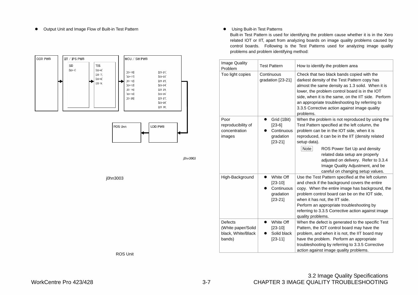
3.2 Image Quality SpecificationsWorkCentre Pro 423/428 3-7 CHAPTER 3 IMAGE QUALITY TROUBLESHOOTING
l Output Unit and Image Flow of Built-in Test Pattern
j0hn3003
l Using Built-in Test PatternsBuilt-in Test Pattern is used for identifying the problem cause whether it is in the Xerorelated IOT or IIT, apart from analyzing boards on image quality problems caused bycontrol boards. Following is the Test Patterns used for analyzing image qualityproblems and problem identifying method:
Image QualityProblem
Test Pattern How to identify the problem area
Too light copies Continuousgradation [23-21]
Check that two black bands copied with thedarkest density of the Test Pattern copy hasalmost the same density as 1.3 solid. When it islower, the problem control board is in the IOTside, when it is the same, on the IIT side. Performan appropriate troubleshooting by referring to3.3.5 Corrective action against image qualityproblems.
Poorreproducibility ofconcentrationimages
l Grid (1Bit)[23-6]
l Continuousgradation[23-21]
When the problem is not reproduced by using theTest Pattern specified at the left column, theproblem can be in the IOT side, when it isreproduced, it can be in the IIT (density relatedsetup data).
Note ROS Power Set Up and densityrelated data setup are properlyadjusted on delivery. Refer to 3.3.4Image Quality Adjustment, and becareful on changing setup values.
High-Background l White Off[23-10]
l Continuousgradation[23-21]
Use the Test Pattern specified at the left columnand check if the background covers the entirecopy. When the entire image has background, theproblem control board can be on the IOT side,when it has not, the IIT side.Perform an appropriate troubleshooting byreferring to 3.3.5 Corrective action against imagequality problems.
Defects(White paper/Solidblack, White/Blackbands)
l White Off[23-10]
l Solid black[23-11]
When the defect is generated to the specific TestPattern, the IOT control board may have theproblem, and when it is not, the IIT board mayhave the problem. Perform an appropriatetroubleshooting by referring to 3.3.5 Correctiveaction against image quality problems.
ROS Unit
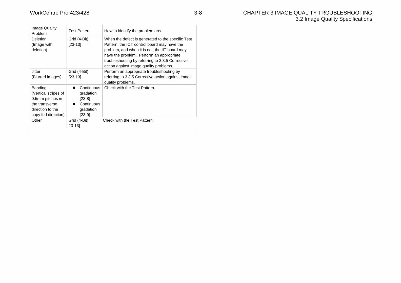
WorkCentre Pro 423/428 3-8 CHAPTER 3 IMAGE QUALITY TROUBLESHOOTING3.2 Image Quality Specifications
Image QualityProblem
Test Pattern How to identify the problem area
Deletion(Image withdeletion)
Grid (4-Bit)[23-13]
When the defect is generated to the specific TestPattern, the IOT control board may have theproblem, and when it is not, the IIT board mayhave the problem. Perform an appropriatetroubleshooting by referring to 3.3.5 Correctiveaction against image quality problems.
Jitter(Blurred images)
Grid (4-Bit)[23-13]
Perform an appropriate troubleshooting byreferring to 3.3.5 Corrective action against imagequality problems.
Banding(Vertical stripes of0.5mm pitches inthe transversedirection to thecopy fed direction)
l Continuousgradation[23-8]
l Continuousgradation[23-9]
Check with the Test Pattern.
Other Grid (4-Bit)23-13]
Check with the Test Pattern.
3.3 Image Quality TroubleshootingWorkCentre Pro 423/428 3-9 CHAPTER 3 IMAGE QUALITY TROUBLESHOOTING
3.3 Image Quality Troubleshooting
3.3.1 Copy Sample
When an image quality problem occurs, make A3 copy samples using Test Pattern(499T247) in order to judge, understand the symptom and execute a suitable correctiveaction. Use Test Pattern (499T281) for image quality problem of printout using the faxsend/receive features.
3.3.2 Cautions on image quality troubleshooting
Image quality problems are usually corrected according to procedures instructed introubleshooting tables corresponding to the problems. When an image quality problemoccurs continuously or an abnormal symptom is observed, check the installationenvironment, originals used and lives of consumables.
1. Installation environmentThe power source voltage must be 100±10%(FX), 110±10%(TFX)220±10%(KX), 220 - 240V±10%(FXA) VAC.l Avoid places subject to high temperature and moisture (near water valves, water
heaters, humidifiers, air-conditioners or fire sources).l Avoid places subject to ammonia gas.l Select places not subject to direct sunshine (if unavoidable, instruct the customer to
install curtains).l Select places with good ventilation.l Select places where the machine can be secured horizontally level.
2. Check of originals causing image quality problemsl Check of original density
• E.g.: Check for wrong judgment of high background when diazo copies ornewspapers are used as originals.
• E.g.: Check for wrong judgment of too light copies when light pencil written orblue no-carbon paper originals are used.
3. Check of consumablesl Check lives of CRU: 24K copies
4. Check of paperl Store paper at a place of low humidity.
5. Host-side check for an image quality faultl Check whether the fault depends on the application.l Try printing from another client.l Try printing by another application.
l Try printing by another icon (file).l Replace the application.l Check the client system.l Try printing by another icon (file).
3.3.3 Basic rules on action against image quality problems
The first thing to be done is cleaning of components.Check for the mirror, lens, ROS window, platen glass, platen cushion, white referenceboard, transport section, and fuser section for contamination and clean, if necessary.Excessive or quick contamination at certain components is often caused by improperenvironmental condition. In such a case, a suitable action should be taken.
3.3.4 Image Quality Adjustment
Proper adjustment has been completed to the machine on delivery and no furtheradjustment should be necessary in the field. However, extra adjustments can be requiredaccording to the customer’s preference.When light copies, high background or too dark density is generated, performtroubleshooting by referring to 3.3.5 Corrective action against image quality problems.When the problem persists, perform adjustment.
1. Diagnostic Code used for Image Quality AdjustmentUse Diag Code [21-5] to [21-57] to perform image quality adjustment.
2. Cautions on image quality adjustmentCheck notes described by symptoms below when performing image quality adjustment.
1) For improving reproducibility of low concentration images as required by the customer(Green or blue characters or lines)
Instruct the customer that density can normally be improved by manually selecting the“Dark” button. When the setup data is changed as described below, confirm with thecustomer that the change may trigger other problems.l Decreasing the Diag Code [21-31] setup data.
Note In this case, threshold level for eliminating the AE ground color decreases and asa result, high background of the originals, such as newspapers, may appear oncopies. Recommend the customer to use the manual density adjustment button.
WorkCentre Pro 423/428 3-10 CHAPTER 3 IMAGE QUALITY TROUBLESHOOTING3.3 Image Quality Troubleshooting
2) Light copiesl Check
1. Check that the values are correctly set up in the Diag Code [21-5] to [21-37]. (SeeNVM table)
2. Check that the ROS window is not contaminated.3. Print out the built-in Test Pattern of continuous gradation in the Diag Code [23-21].
Check that the darkest two black bands in the Test Pattern copy has almost thesame density as 1.3 solid.• When the density is lower, the problem can be Xero related.• When the density is almost the same, the IIT may have the problem.
l When the density of built-in Test Pattern is normalA. Check the IIT.
• When the auto controlled density is too lightCheck that the setup data in the Diag Codes below are appropriate. (See NVMtable) Change the data as needed. [21-25,26,31to37]
• When the manually controlled density is too lightCheck that the setup data in the Diag Codes below are appropriate. (See NVMtable) Change the data as needed. [21-5 to 24]
B. Check the control board.Problem of control board rarely causes light copies, but when the problem persistsafter conducting the above checks, use a built-in Test Pattern and check eachboard for problems.
3) When the image is too light at one half side of copy
Print out the built-in Test Pattern with continuous gradation in the Diag Code [23-23].Check for a light image at one half side of the copy.l When the outboard side (front side of the machine) is light,
� The CRU has not been properly installed.l When the built-in Test Patterns does not show light images, check the IIT white
reference board for contamination. (Particularly for the DADF white referenceboard)
4) High background for the entire image or density is too dark
Print out the built-in Test Pattern of the entire white copy in the Diag Code [23-10] andof continuous gradation in the Diag Code [23-23]. Check for high-background in theentire image.� When the entire image has background, poor toner charging can be the cause.
(Replace the CRU.)
When the built-in Test Pattern has background, check XERO related components(CRU, BTR, or DST) for problems.
• Replace the CRU, then HVPS.
l When the built-in Test Pattern has no backgroundA. Check the IIT.
• When background is observed in the auto adjusted densityCheck the data setup in the Diag Codes [21-25] to [21-57] are appropriate.(See NVM table) Change the data as needed.
• When background is observed in the manually adjusted density• Check the white reference board for pieces of paper, dust or foreign
matter.• Check that the data setup in the Diag Codes [21-5 to 24] are appropriate.
(See NVM table) Change the data as needed.
B. Check the control board.If the problem persists, use the built-in Test Pattern to check each board forproblems.
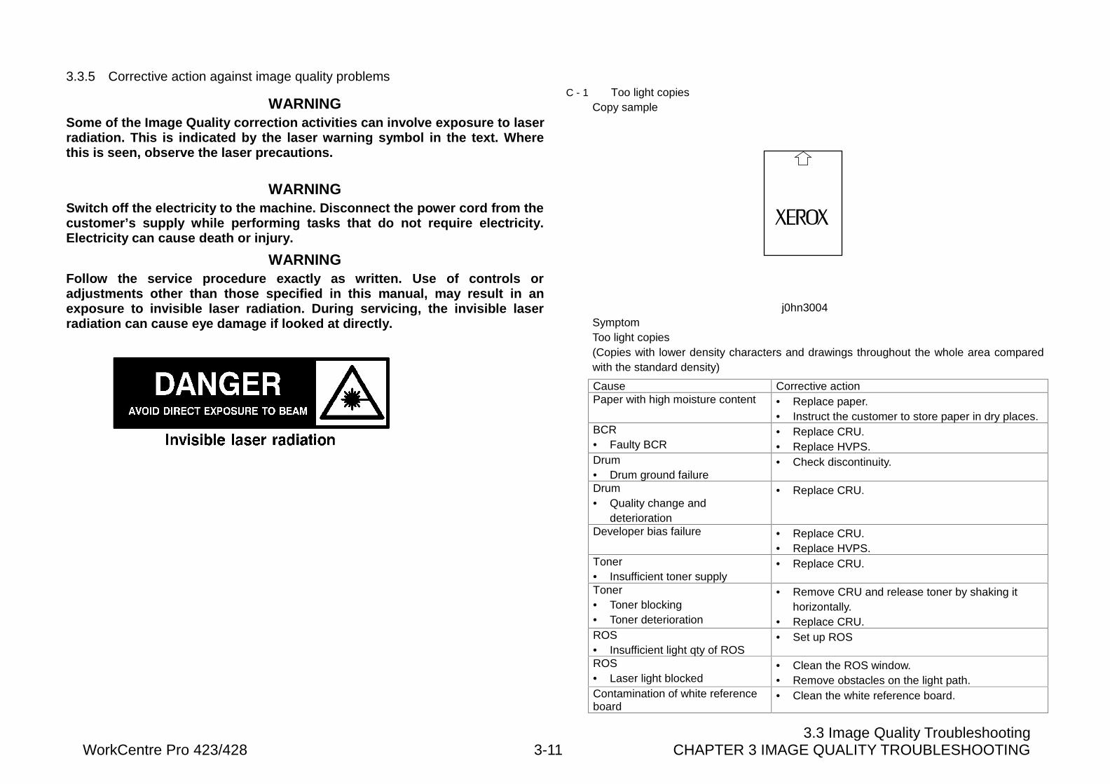
3.3 Image Quality TroubleshootingWorkCentre Pro 423/428 3-11 CHAPTER 3 IMAGE QUALITY TROUBLESHOOTING
3.3.5 Corrective action against image quality problems
WARNINGSome of the Image Quality correction activities can involve exposure to laserradiation. This is indicated by the laser warning symbol in the text. Wherethis is seen, observe the laser precautions.
WARNINGSwitch off the electricity to the machine. Disconnect the power cord from thecustomer’s supply while performing tasks that do not require electricity.Electricity can cause death or injury.
WARNINGFollow the service procedure exactly as written. Use of controls oradjustments other than those specified in this manual, may result in anexposure to invisible laser radiation. During servicing, the invisible laserradiation can cause eye damage if looked at directly.
C - 1 Too light copiesCopy sample
j0hn3004SymptomToo light copies(Copies with lower density characters and drawings throughout the whole area comparedwith the standard density)
Cause Corrective actionPaper with high moisture content • Replace paper.
• Instruct the customer to store paper in dry places.BCR• Faulty BCR
• Replace CRU.• Replace HVPS.
Drum• Drum ground failure
• Check discontinuity.
Drum• Quality change and
deterioration
• Replace CRU.
Developer bias failure • Replace CRU.• Replace HVPS.
Toner• Insufficient toner supply
• Replace CRU.
Toner• Toner blocking• Toner deterioration
• Remove CRU and release toner by shaking ithorizontally.
• Replace CRU.ROS• Insufficient light qty of ROS
• Set up ROS
ROS• Laser light blocked
• Clean the ROS window.• Remove obstacles on the light path.
Contamination of white referenceboard
• Clean the white reference board.
WorkCentre Pro 423/428 3-12 CHAPTER 3 IMAGE QUALITY TROUBLESHOOTING3.3 Image Quality Troubleshooting
Cause Corrective actionInappropriate AE setup data • Check NVM setup data. [21-37]Inappropriate shadingcompensation coefficient
• Check NVM setup data. [21-56][21-57]
Control Board• Faulty MCU/SW PWB or
IIT/IPS PWB
• Print out built-in Test Pattern (continuousgradation) to check and isolate faulty board.
Control Board• Connection failure of MCU/SW
PWB, IIT/IPS PWB, MF MAINPWB
• Check that the connections are secure.
Control Board• Faulty CCD PWB
• Replace CCD PWB.
Density setup failure • Check NVM setup data.(Diag [21-5 to 57])
C - 2 White copiesCopy sample
j0hn3005SymptomWhite copies (Output of entirely white copies without characters and drawings)
Cause Corrective actionDrum• Drum revolution failure
• Check the CRU drive structure.
Drum• Quality change and
deterioration
• Replace CRU.
Drum• Magnetic roller revolution
failure
• Check CRU and drive structure.
Developer bias• Output failure of HVPS
• Replace HVPS.
Developer bias• Discontinuity of magnetic roller
• Check continuity of magnetic roll.
Interrupted laser path • Check for foreign matter in the laser path betweenROS and drum.
Control board• Faulty MCU/SW PWB or
IIT/IPS PWB
• Print out built-in Test Pattern to check and isolatefaulty board.
Control board• Connection failure between
PWBs
• Check connectors for connection.
Control board• Faulty CCD PWB
• Replace CCD PWB.
Poor contact of BTR • Repair or replace BTR.
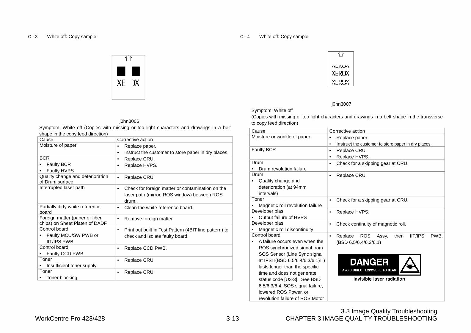
3.3 Image Quality TroubleshootingWorkCentre Pro 423/428 3-13 CHAPTER 3 IMAGE QUALITY TROUBLESHOOTING
C - 3 White off: Copy sample
j0hn3006Symptom: White off (Copies with missing or too light characters and drawings in a beltshape in the copy feed direction)Cause Corrective actionMoisture of paper • Replace paper.
• Instruct the customer to store paper in dry places.BCR• Faulty BCR• Faulty HVPS
• Replace CRU.• Replace HVPS.
Quality change and deteriorationof Drum surface
• Replace CRU.
Interrupted laser path • Check for foreign matter or contamination on thelaser path (mirror, ROS window) between ROSdrum.
Partially dirty white referenceboard
• Clean the white reference board.
Foreign matter (paper or fiberchips) on Sheet Platen of DADF
• Remove foreign matter.
Control board• Faulty MCU/SW PWB or
IIT/IPS PWB
• Print out built-in Test Pattern (4BIT line pattern) tocheck and isolate faulty board.
Control board• Faulty CCD PWB
• Replace CCD PWB.
Toner• Insufficient toner supply
• Replace CRU.
Toner• Toner blocking
• Replace CRU.
C - 4 White off: Copy sample
j0hn3007Symptom: White off(Copies with missing or too light characters and drawings in a belt shape in the transverseto copy feed direction)
Cause Corrective actionMoisture or wrinkle of paper • Replace paper.
• Instruct the customer to store paper in dry places.Faulty BCR • Replace CRU.
• Replace HVPS.Drum• Drum revolution failure
• Check for a skipping gear at CRU.
Drum• Quality change and
deterioration (at 94mmintervals)
• Replace CRU.
Toner• Magnetic roll revolution failure
• Check for a skipping gear at CRU.
Developer bias• Output failure of HVPS
• Replace HVPS.
Developer bias• Magnetic roll discontinuity
• Check continuity of magnetic roll.
Control board• A failure occurs even when the
ROS synchronized signal fromSOS Sensor (Line Sync signalat IPS�(BSD 6.5/6.4/6.3/6.1)�)lasts longer than the specifictime and does not generatestatus code [U3-3]. See BSD6.5/6.3/6.4. SOS signal failure,lowered ROS Power, orrevolution failure of ROS Motor
• Replace ROS Assy, then IIT/IPS PWB.(BSD 6.5/6.4/6.3/6.1)
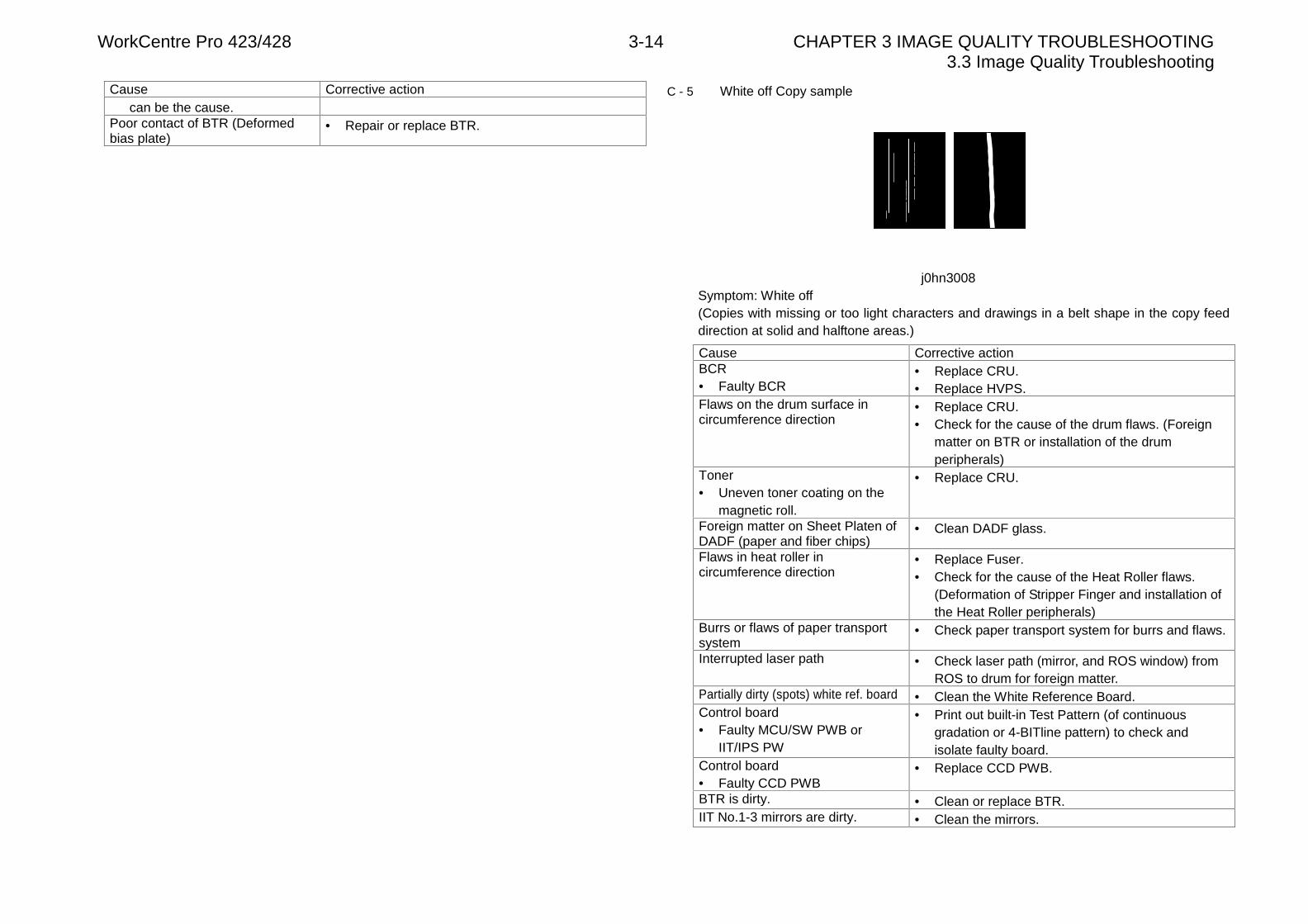
WorkCentre Pro 423/428 3-14 CHAPTER 3 IMAGE QUALITY TROUBLESHOOTING3.3 Image Quality Troubleshooting
Cause Corrective actioncan be the cause.
Poor contact of BTR (Deformedbias plate)
• Repair or replace BTR.
C - 5 White off Copy sample
j0hn3008Symptom: White off(Copies with missing or too light characters and drawings in a belt shape in the copy feeddirection at solid and halftone areas.)
Cause Corrective actionBCR• Faulty BCR
• Replace CRU.• Replace HVPS.
Flaws on the drum surface incircumference direction
• Replace CRU.• Check for the cause of the drum flaws. (Foreign
matter on BTR or installation of the drumperipherals)
Toner• Uneven toner coating on the
magnetic roll.
• Replace CRU.
Foreign matter on Sheet Platen ofDADF (paper and fiber chips)
• Clean DADF glass.
Flaws in heat roller incircumference direction
• Replace Fuser.• Check for the cause of the Heat Roller flaws.
(Deformation of Stripper Finger and installation ofthe Heat Roller peripherals)
Burrs or flaws of paper transportsystem
• Check paper transport system for burrs and flaws.
Interrupted laser path • Check laser path (mirror, and ROS window) fromROS to drum for foreign matter.
Partially dirty (spots) white ref. board • Clean the White Reference Board.Control board• Faulty MCU/SW PWB or
IIT/IPS PW
• Print out built-in Test Pattern (of continuousgradation or 4-BITline pattern) to check andisolate faulty board.
Control board• Faulty CCD PWB
• Replace CCD PWB.
BTR is dirty. • Clean or replace BTR.IIT No.1-3 mirrors are dirty. • Clean the mirrors.
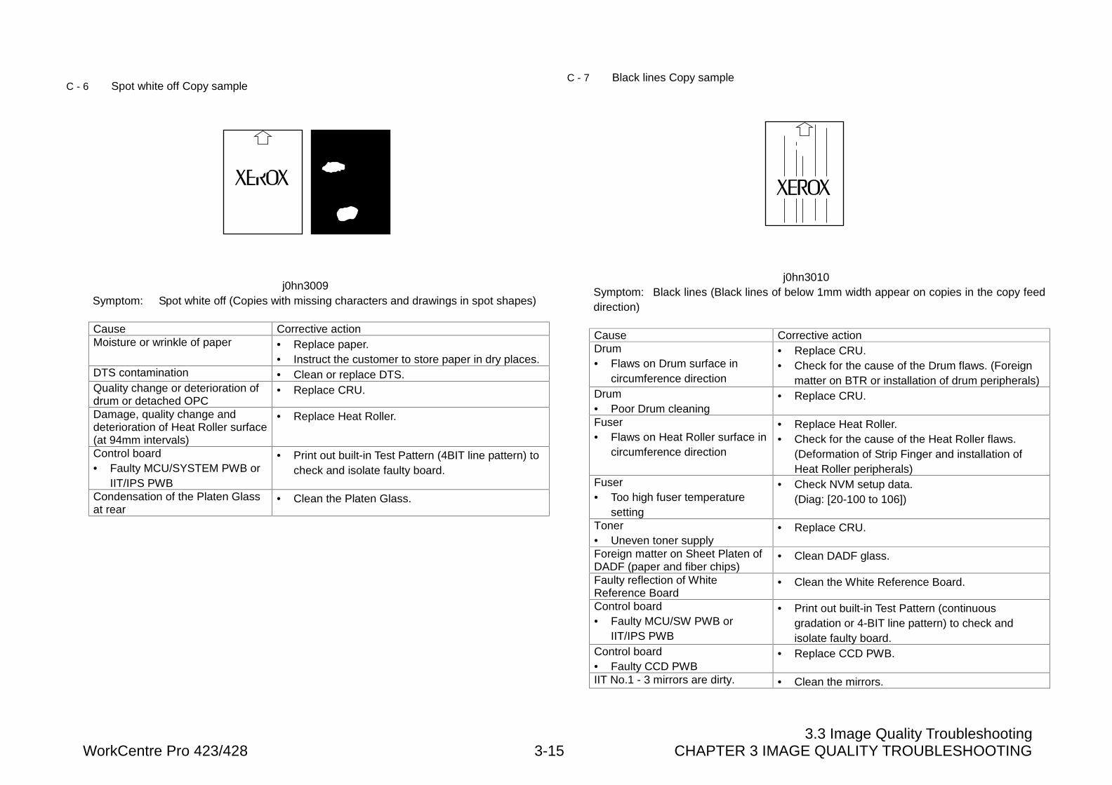
3.3 Image Quality TroubleshootingWorkCentre Pro 423/428 3-15 CHAPTER 3 IMAGE QUALITY TROUBLESHOOTING
C - 6 Spot white off Copy sample
j0hn3009Symptom: Spot white off (Copies with missing characters and drawings in spot shapes)
Cause Corrective actionMoisture or wrinkle of paper • Replace paper.
• Instruct the customer to store paper in dry places.DTS contamination • Clean or replace DTS.Quality change or deterioration ofdrum or detached OPC
• Replace CRU.
Damage, quality change anddeterioration of Heat Roller surface(at 94mm intervals)
• Replace Heat Roller.
Control board• Faulty MCU/SYSTEM PWB or
IIT/IPS PWB
• Print out built-in Test Pattern (4BIT line pattern) tocheck and isolate faulty board.
Condensation of the Platen Glassat rear
• Clean the Platen Glass.
C - 7 Black lines Copy sample
j0hn3010Symptom: Black lines (Black lines of below 1mm width appear on copies in the copy feeddirection)
Cause Corrective actionDrum• Flaws on Drum surface in
circumference direction
• Replace CRU.• Check for the cause of the Drum flaws. (Foreign
matter on BTR or installation of drum peripherals)Drum• Poor Drum cleaning
• Replace CRU.
Fuser• Flaws on Heat Roller surface in
circumference direction
• Replace Heat Roller.• Check for the cause of the Heat Roller flaws.
(Deformation of Strip Finger and installation ofHeat Roller peripherals)
Fuser• Too high fuser temperature
setting
• Check NVM setup data.(Diag: [20-100 to 106])
Toner• Uneven toner supply
• Replace CRU.
Foreign matter on Sheet Platen ofDADF (paper and fiber chips)
• Clean DADF glass.
Faulty reflection of WhiteReference Board
• Clean the White Reference Board.
Control board• Faulty MCU/SW PWB or
IIT/IPS PWB
• Print out built-in Test Pattern (continuousgradation or 4-BIT line pattern) to check andisolate faulty board.
Control board• Faulty CCD PWB
• Replace CCD PWB.
IIT No.1 - 3 mirrors are dirty. • Clean the mirrors.
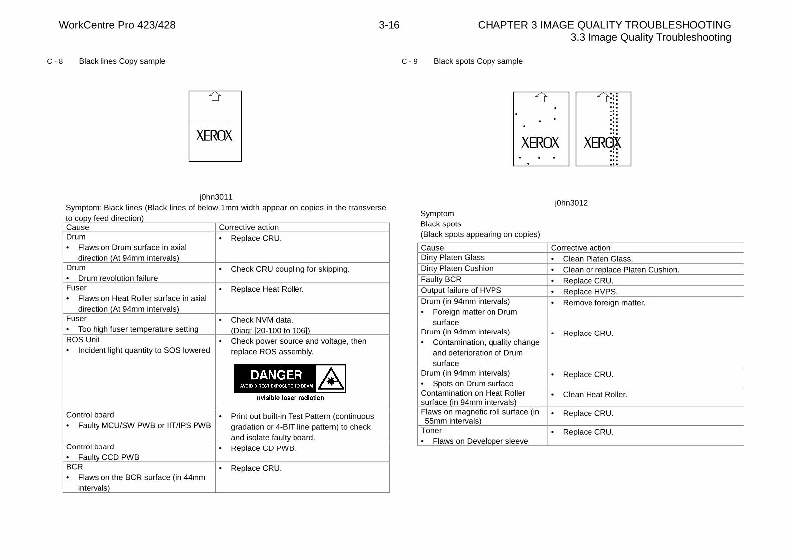
WorkCentre Pro 423/428 3-16 CHAPTER 3 IMAGE QUALITY TROUBLESHOOTING3.3 Image Quality Troubleshooting
C - 8 Black lines Copy sample
j0hn3011Symptom: Black lines (Black lines of below 1mm width appear on copies in the transverseto copy feed direction)Cause Corrective actionDrum• Flaws on Drum surface in axial
direction (At 94mm intervals)
• Replace CRU.
Drum• Drum revolution failure
• Check CRU coupling for skipping.
Fuser• Flaws on Heat Roller surface in axial
direction (At 94mm intervals)
• Replace Heat Roller.
Fuser• Too high fuser temperature setting
• Check NVM data.(Diag: [20-100 to 106])
ROS Unit• Incident light quantity to SOS lowered
• Check power source and voltage, thenreplace ROS assembly.
Control board• Faulty MCU/SW PWB or IIT/IPS PWB
• Print out built-in Test Pattern (continuousgradation or 4-BIT line pattern) to checkand isolate faulty board.
Control board• Faulty CCD PWB
• Replace CD PWB.
BCR• Flaws on the BCR surface (in 44mm
intervals)
• Replace CRU.
C - 9 Black spots Copy sample
j0hn3012SymptomBlack spots(Black spots appearing on copies)
Cause Corrective actionDirty Platen Glass • Clean Platen Glass.Dirty Platen Cushion • Clean or replace Platen Cushion.Faulty BCR • Replace CRU.Output failure of HVPS • Replace HVPS.Drum (in 94mm intervals)• Foreign matter on Drum
surface
• Remove foreign matter.
Drum (in 94mm intervals)• Contamination, quality change
and deterioration of Drumsurface
• Replace CRU.
Drum (in 94mm intervals)• Spots on Drum surface
• Replace CRU.
Contamination on Heat Rollersurface (in 94mm intervals)
• Clean Heat Roller.
Flaws on magnetic roll surface (in55mm intervals)
• Replace CRU.
Toner• Flaws on Developer sleeve
• Replace CRU.
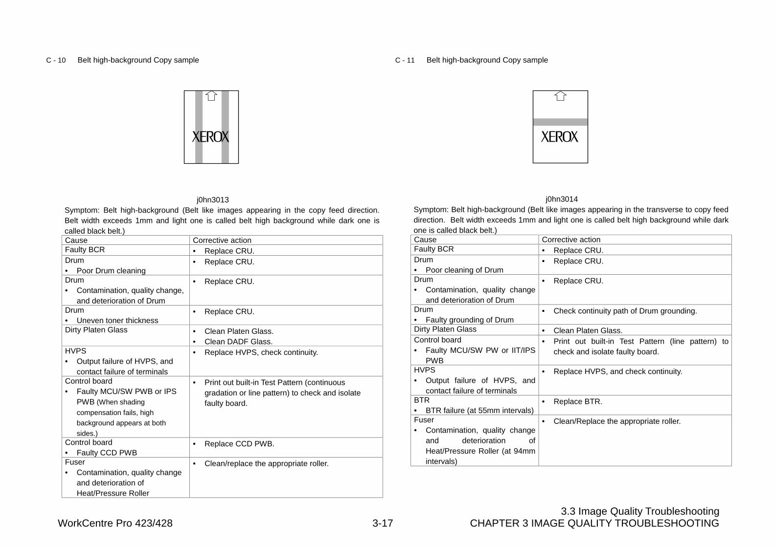
3.3 Image Quality TroubleshootingWorkCentre Pro 423/428 3-17 CHAPTER 3 IMAGE QUALITY TROUBLESHOOTING
C - 10 Belt high-background Copy sample
j0hn3013Symptom: Belt high-background (Belt like images appearing in the copy feed direction.Belt width exceeds 1mm and light one is called belt high background while dark one iscalled black belt.)Cause Corrective actionFaulty BCR • Replace CRU.Drum• Poor Drum cleaning
• Replace CRU.
Drum• Contamination, quality change,
and deterioration of Drum
• Replace CRU.
Drum• Uneven toner thickness
• Replace CRU.
Dirty Platen Glass • Clean Platen Glass.• Clean DADF Glass.
HVPS• Output failure of HVPS, and
contact failure of terminals
• Replace HVPS, check continuity.
Control board• Faulty MCU/SW PWB or IPS
PWB (When shading
compensation fails, high
background appears at both
sides.)
• Print out built-in Test Pattern (continuousgradation or line pattern) to check and isolatefaulty board.
Control board• Faulty CCD PWB
• Replace CCD PWB.
Fuser• Contamination, quality change
and deterioration ofHeat/Pressure Roller
• Clean/replace the appropriate roller.
C - 11 Belt high-background Copy sample
j0hn3014Symptom: Belt high-background (Belt like images appearing in the transverse to copy feeddirection. Belt width exceeds 1mm and light one is called belt high background while darkone is called black belt.)Cause Corrective actionFaulty BCR • Replace CRU.Drum• Poor cleaning of Drum
• Replace CRU.
Drum• Contamination, quality change
and deterioration of Drum
• Replace CRU.
Drum• Faulty grounding of Drum
• Check continuity path of Drum grounding.
Dirty Platen Glass • Clean Platen Glass.Control board• Faulty MCU/SW PW or IIT/IPS
PWB
• Print out built-in Test Pattern (line pattern) tocheck and isolate faulty board.
HVPS• Output failure of HVPS, and
contact failure of terminals
• Replace HVPS, and check continuity.
BTR• BTR failure (at 55mm intervals)
• Replace BTR.
Fuser• Contamination, quality change
and deterioration ofHeat/Pressure Roller (at 94mmintervals)
• Clean/Replace the appropriate roller.
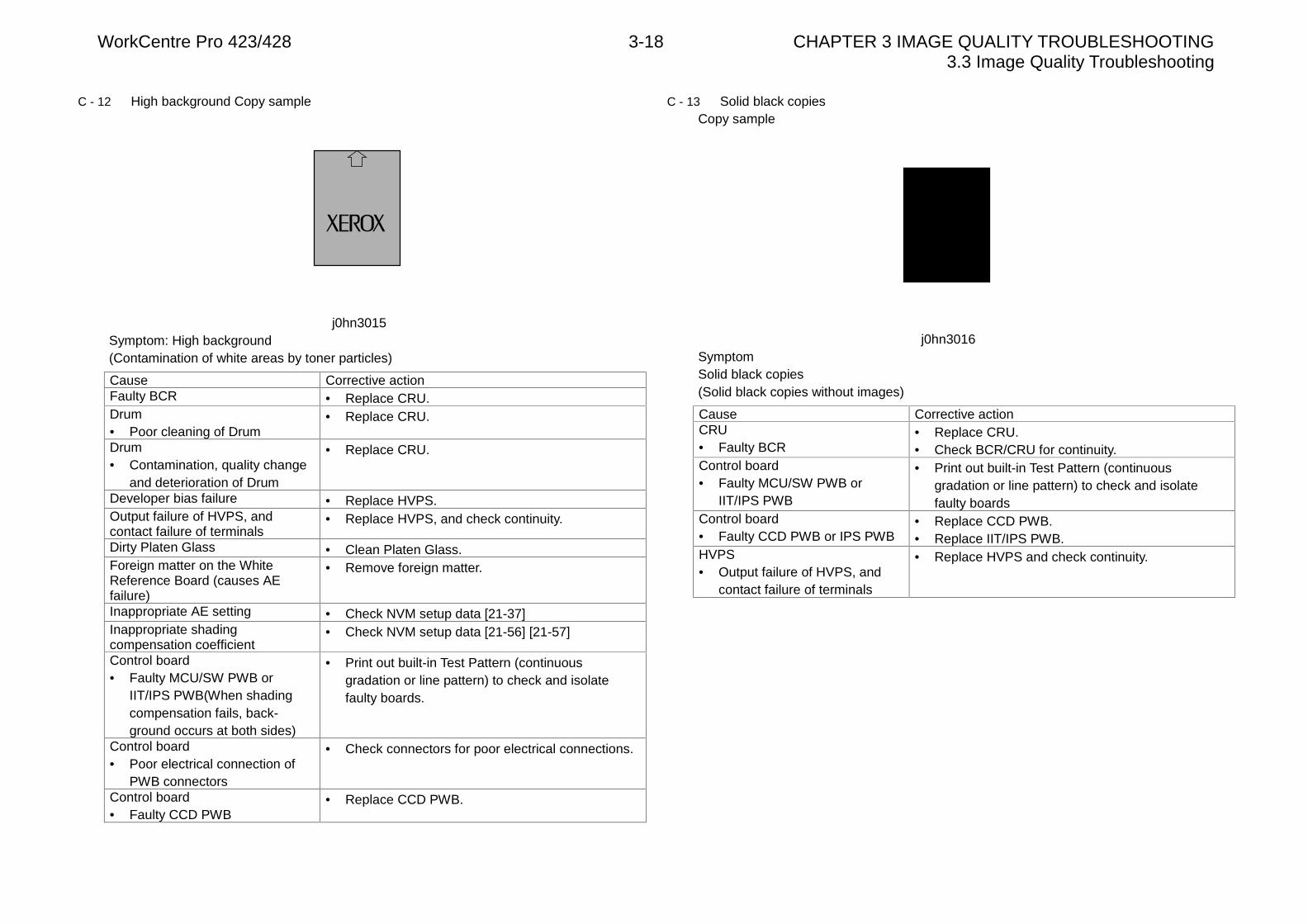
WorkCentre Pro 423/428 3-18 CHAPTER 3 IMAGE QUALITY TROUBLESHOOTING3.3 Image Quality Troubleshooting
C - 12 High background Copy sample
j0hn3015Symptom: High background(Contamination of white areas by toner particles)
Cause Corrective actionFaulty BCR • Replace CRU.Drum• Poor cleaning of Drum
• Replace CRU.
Drum• Contamination, quality change
and deterioration of Drum
• Replace CRU.
Developer bias failure • Replace HVPS.Output failure of HVPS, andcontact failure of terminals
• Replace HVPS, and check continuity.
Dirty Platen Glass • Clean Platen Glass.Foreign matter on the WhiteReference Board (causes AEfailure)
• Remove foreign matter.
Inappropriate AE setting • Check NVM setup data [21-37]Inappropriate shadingcompensation coefficient
• Check NVM setup data [21-56] [21-57]
Control board• Faulty MCU/SW PWB or
IIT/IPS PWB(When shadingcompensation fails, back-ground occurs at both sides)
• Print out built-in Test Pattern (continuousgradation or line pattern) to check and isolatefaulty boards.
Control board• Poor electrical connection of
PWB connectors
• Check connectors for poor electrical connections.
Control board• Faulty CCD PWB
• Replace CCD PWB.
C - 13 Solid black copiesCopy sample
j0hn3016SymptomSolid black copies(Solid black copies without images)
Cause Corrective actionCRU• Faulty BCR
• Replace CRU.• Check BCR/CRU for continuity.
Control board• Faulty MCU/SW PWB or
IIT/IPS PWB
• Print out built-in Test Pattern (continuousgradation or line pattern) to check and isolatefaulty boards
Control board• Faulty CCD PWB or IPS PWB
• Replace CCD PWB.• Replace IIT/IPS PWB.
HVPS• Output failure of HVPS, and
contact failure of terminals
• Replace HVPS and check continuity.
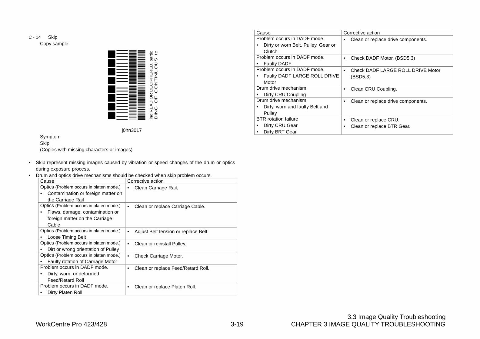
3.3 Image Quality TroubleshootingWorkCentre Pro 423/428 3-19 CHAPTER 3 IMAGE QUALITY TROUBLESHOOTING
C - 14 SkipCopy sample
ing
RE
AD
OR
DE
CIP
HE
RE
D,
pa
rtic
DIN
G
OF
C
ON
TIN
UO
US
te
j0hn3017SymptomSkip(Copies with missing characters or images)
• Skip represent missing images caused by vibration or speed changes of the drum or opticsduring exposure process.
• Drum and optics drive mechanisms should be checked when skip problem occurs.Cause Corrective actionOptics (Problem occurs in platen mode.)
• Contamination or foreign matter onthe Carriage Rail
• Clean Carriage Rail.
Optics (Problem occurs in platen mode.)
• Flaws, damage, contamination orforeign matter on the CarriageCable
• Clean or replace Carriage Cable.
Optics (Problem occurs in platen mode.)
• Loose Timing Belt• Adjust Belt tension or replace Belt.
Optics (Problem occurs in platen mode.)
• Dirt or wrong orientation of Pulley• Clean or reinstall Pulley.
Optics (Problem occurs in platen mode.)
• Faulty rotation of Carriage Motor• Check Carriage Motor.
Problem occurs in DADF mode.• Dirty, worn, or deformed
Feed/Retard Roll
• Clean or replace Feed/Retard Roll.
Problem occurs in DADF mode.• Dirty Platen Roll
• Clean or replace Platen Roll.
Cause Corrective actionProblem occurs in DADF mode.• Dirty or worn Belt, Pulley, Gear or
Clutch
• Clean or replace drive components.
Problem occurs in DADF mode.• Faulty DADF
• Check DADF Motor. (BSD5.3)
Problem occurs in DADF mode.• Faulty DADF LARGE ROLL DRIVE
Motor
• Check DADF LARGE ROLL DRIVE Motor(BSD5.3)
Drum drive mechanism• Dirty CRU Coupling
• Clean CRU Coupling.
Drum drive mechanism• Dirty, worn and faulty Belt and
Pulley
• Clean or replace drive components.
BTR rotation failure• Dirty CRU Gear• Dirty BRT Gear
• Clean or replace CRU.• Clean or replace BTR Gear.
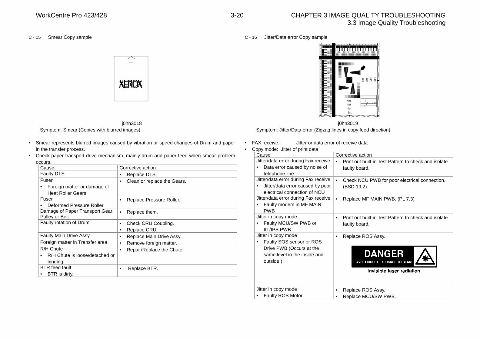
WorkCentre Pro 423/428 3-20 CHAPTER 3 IMAGE QUALITY TROUBLESHOOTING3.3 Image Quality Troubleshooting
C - 15 Smear Copy sample
j0hn3018Symptom: Smear (Copies with blurred images)
• Smear represents blurred images caused by vibration or speed changes of Drum and paperin the transfer process.
• Check paper transport drive mechanism, mainly drum and paper feed when smear problemoccurs.
Cause Corrective actionFaulty DTS • Replace DTS.Fuser• Foreign matter or damage of
Heat Roller Gears
• Clean or replace the Gears.
Fuser• Deformed Pressure Roller
• Replace Pressure Roller.
Damage of Paper Transport Gear,Pulley or Belt
• Replace them.
Faulty rotation of Drum • Check CRU Coupling.• Replace CRU.
Faulty Main Drive Assy • Replace Main Drive Assy.Foreign matter in Transfer area • Remove foreign matter.R/H Chute• R/H Chute is loose/detached or
binding.
• Repair/Replace the Chute.
BTR feed fault• BTR is dirty.
• Replace BTR.
C - 16 Jitter/Data error Copy sample
j0hn3019Symptom: Jitter/Data error (Zigzag lines in copy feed direction)
• FAX receive: Jitter or data error of receive data• Copy mode: Jitter of print data
Cause Corrective actionJitter/data error during Fax receive• Data error caused by noise of
telephone line
• Print out built-in Test Pattern to check and isolatefaulty board.
Jitter/data error during Fax receive• Jitter/data error caused by poor
electrical connection of NCU
• Check NCU PWB for poor electrical connection.(BSD 19.2)
Jitter/data error during Fax receive• Faulty modem in MF MAIN
PWB
• Replace MF MAIN PWB. (PL 7.3)
Jitter in copy mode• Faulty MCU/SW PWB or
IIT/IPS PWB
• Print out built-in Test Pattern to check and isolatefaulty board.
Jitter in copy mode• Faulty SOS sensor or ROS
Drive PWB (Occurs at thesame level in the inside andoutside.)
• Replace ROS Assy.
Jitter in copy mode• Faulty ROS Motor
• Replace ROS Assy.• Replace MCU/SW PWB.
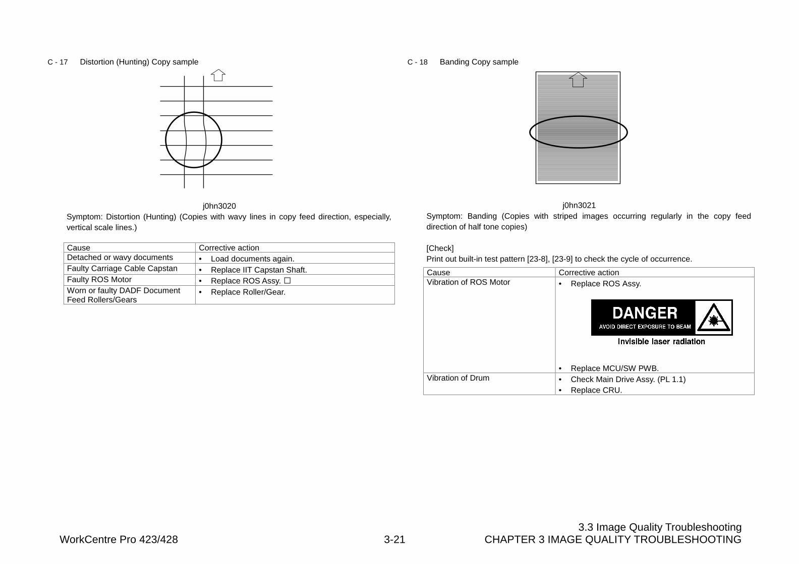
3.3 Image Quality TroubleshootingWorkCentre Pro 423/428 3-21 CHAPTER 3 IMAGE QUALITY TROUBLESHOOTING
C - 17 Distortion (Hunting) Copy sample
j0hn3020Symptom: Distortion (Hunting) (Copies with wavy lines in copy feed direction, especially,vertical scale lines.)
Cause Corrective actionDetached or wavy documents • Load documents again.Faulty Carriage Cable Capstan • Replace IIT Capstan Shaft.Faulty ROS Motor • Replace ROS Assy. �Worn or faulty DADF DocumentFeed Rollers/Gears
• Replace Roller/Gear.
C - 18 Banding Copy sample
j0hn3021Symptom: Banding (Copies with striped images occurring regularly in the copy feeddirection of half tone copies)
[Check]Print out built-in test pattern [23-8], [23-9] to check the cycle of occurrence.
Cause Corrective actionVibration of ROS Motor • Replace ROS Assy.
• Replace MCU/SW PWB.Vibration of Drum • Check Main Drive Assy. (PL 1.1)
• Replace CRU.
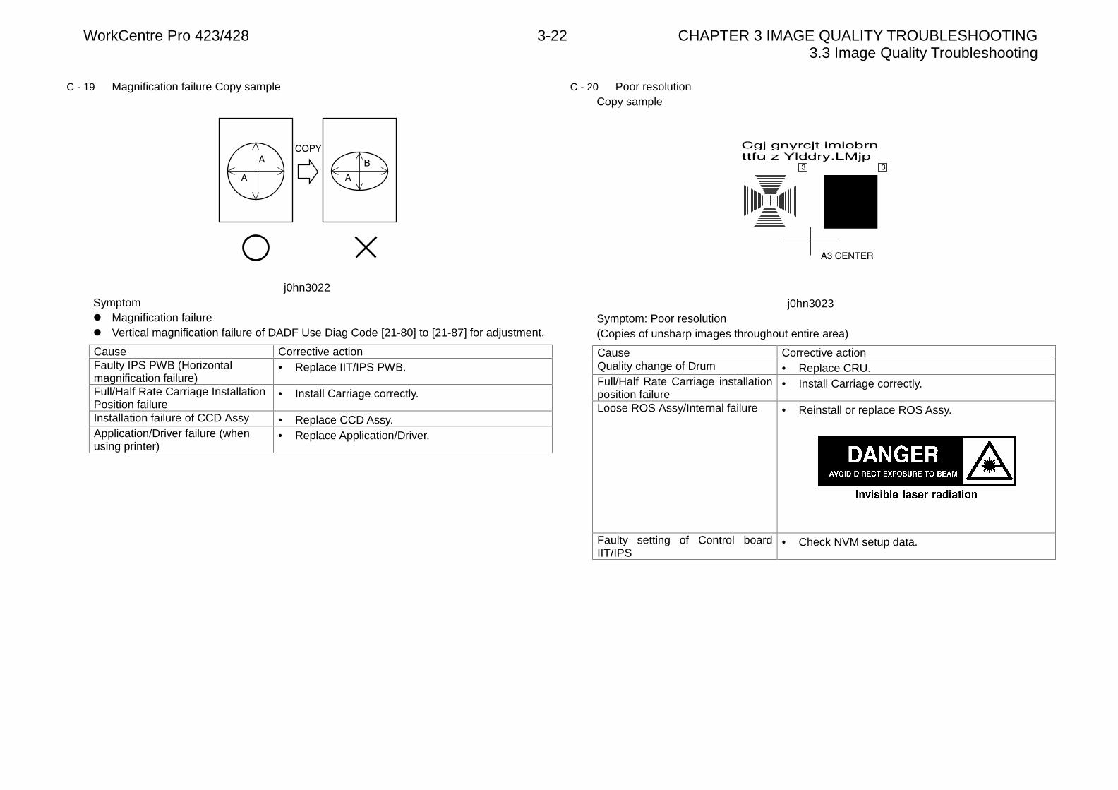
WorkCentre Pro 423/428 3-22 CHAPTER 3 IMAGE QUALITY TROUBLESHOOTING3.3 Image Quality Troubleshooting
C - 19 Magnification failure Copy sample
j0hn3022Symptoml Magnification failurel Vertical magnification failure of DADF Use Diag Code [21-80] to [21-87] for adjustment.
Cause Corrective actionFaulty IPS PWB (Horizontalmagnification failure)
• Replace IIT/IPS PWB.
Full/Half Rate Carriage InstallationPosition failure
• Install Carriage correctly.
Installation failure of CCD Assy • Replace CCD Assy.Application/Driver failure (whenusing printer)
• Replace Application/Driver.
C - 20 Poor resolutionCopy sample
j0hn3023Symptom: Poor resolution(Copies of unsharp images throughout entire area)
Cause Corrective actionQuality change of Drum • Replace CRU.Full/Half Rate Carriage installationposition failure
• Install Carriage correctly.
Loose ROS Assy/Internal failure • Reinstall or replace ROS Assy.
Faulty setting of Control boardIIT/IPS
• Check NVM setup data.
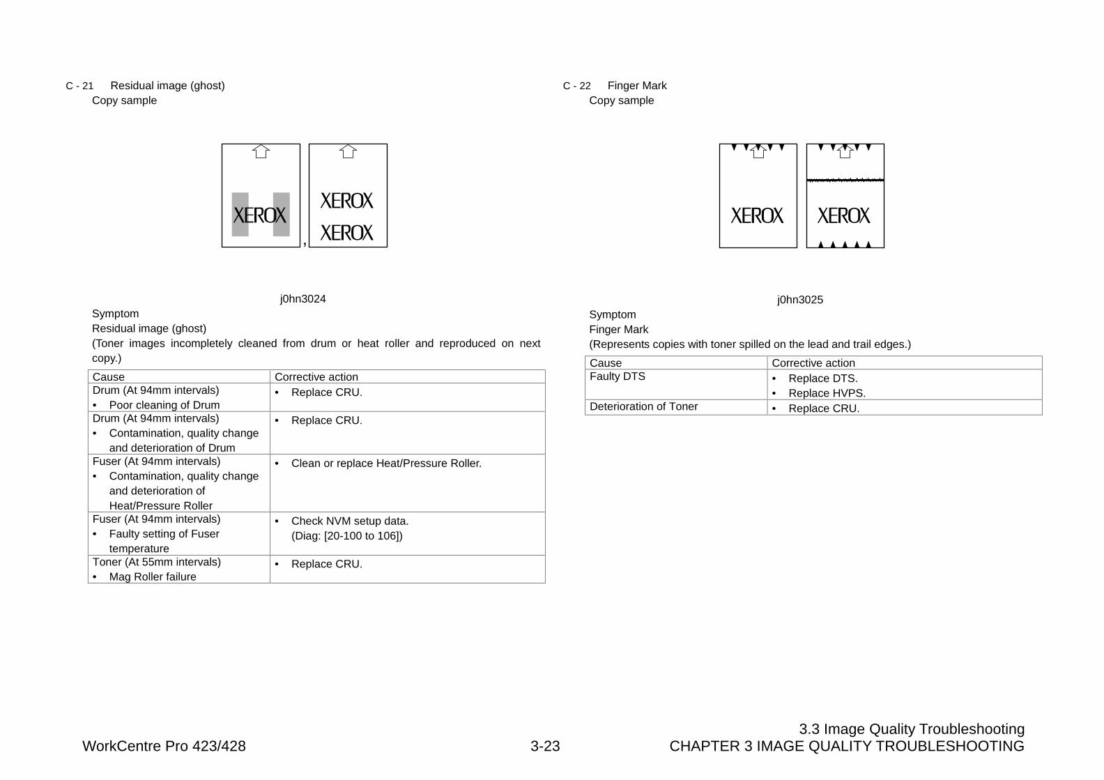
3.3 Image Quality TroubleshootingWorkCentre Pro 423/428 3-23 CHAPTER 3 IMAGE QUALITY TROUBLESHOOTING
C - 21 Residual image (ghost)Copy sample
j0hn3024SymptomResidual image (ghost)(Toner images incompletely cleaned from drum or heat roller and reproduced on nextcopy.)
Cause Corrective actionDrum (At 94mm intervals)• Poor cleaning of Drum
• Replace CRU.
Drum (At 94mm intervals)• Contamination, quality change
and deterioration of Drum
• Replace CRU.
Fuser (At 94mm intervals)• Contamination, quality change
and deterioration ofHeat/Pressure Roller
• Clean or replace Heat/Pressure Roller.
Fuser (At 94mm intervals)• Faulty setting of Fuser
temperature
• Check NVM setup data.(Diag: [20-100 to 106])
Toner (At 55mm intervals)• Mag Roller failure
• Replace CRU.
C - 22 Finger MarkCopy sample
j0hn3025SymptomFinger Mark(Represents copies with toner spilled on the lead and trail edges.)
Cause Corrective actionFaulty DTS • Replace DTS.
• Replace HVPS.Deterioration of Toner • Replace CRU.
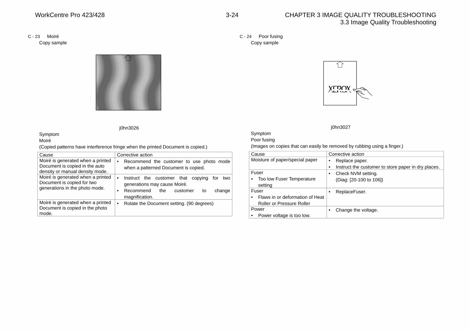
WorkCentre Pro 423/428 3-24 CHAPTER 3 IMAGE QUALITY TROUBLESHOOTING3.3 Image Quality Troubleshooting
C - 23 MoiréCopy sample
j0hn3026SymptomMoiré(Copied patterns have interference fringe when the printed Document is copied.)
Cause Corrective actionMoiré is generated when a printedDocument is copied in the autodensity or manual density mode.
• Recommend the customer to use photo modewhen a patterned Document is copied.
Moiré is generated when a printedDocument is copied for twogenerations in the photo mode.
• Instruct the customer that copying for twogenerations may cause Moiré.
• Recommend the customer to changemagnification.
Moiré is generated when a printedDocument is copied in the photomode.
• Rotate the Document setting. (90 degrees)
C - 24 Poor fusingCopy sample
j0hn3027SymptomPoor fusing(Images on copies that can easily be removed by rubbing using a finger.)
Cause Corrective actionMoisture of paper/special paper • Replace paper.
• Instruct the customer to store paper in dry places.Fuser• Too low Fuser Temperature
setting
• Check NVM setting.(Diag: [20-100 to 106])
Fuser• Flaws in or deformation of Heat
Roller or Pressure Roller
• ReplaceFuser.
Power• Power voltage is too low.
• Change the voltage.
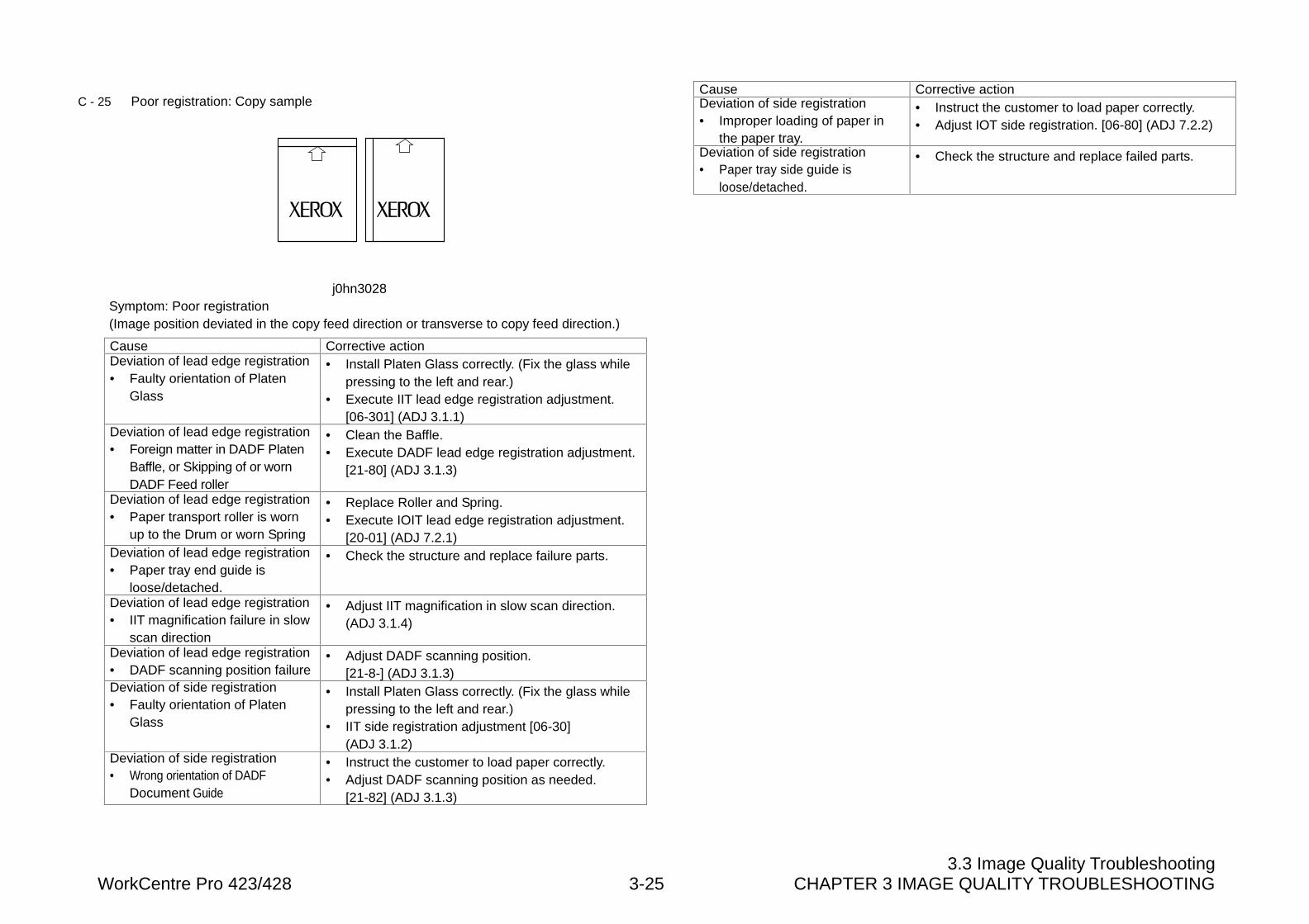
3.3 Image Quality TroubleshootingWorkCentre Pro 423/428 3-25 CHAPTER 3 IMAGE QUALITY TROUBLESHOOTING
C - 25 Poor registration: Copy sample
j0hn3028Symptom: Poor registration(Image position deviated in the copy feed direction or transverse to copy feed direction.)
Cause Corrective actionDeviation of lead edge registration• Faulty orientation of Platen
Glass
• Install Platen Glass correctly. (Fix the glass whilepressing to the left and rear.)
• Execute IIT lead edge registration adjustment.[06-301] (ADJ 3.1.1)
Deviation of lead edge registration• Foreign matter in DADF Platen
Baffle, or Skipping of or wornDADF Feed roller
• Clean the Baffle.• Execute DADF lead edge registration adjustment.
[21-80] (ADJ 3.1.3)
Deviation of lead edge registration• Paper transport roller is worn
up to the Drum or worn Spring
• Replace Roller and Spring.• Execute IOIT lead edge registration adjustment.
[20-01] (ADJ 7.2.1)Deviation of lead edge registration• Paper tray end guide is
loose/detached.
• Check the structure and replace failure parts.
Deviation of lead edge registration• IIT magnification failure in slow
scan direction
• Adjust IIT magnification in slow scan direction.(ADJ 3.1.4)
Deviation of lead edge registration• DADF scanning position failure
• Adjust DADF scanning position.[21-8-] (ADJ 3.1.3)
Deviation of side registration• Faulty orientation of Platen
Glass
• Install Platen Glass correctly. (Fix the glass whilepressing to the left and rear.)
• IIT side registration adjustment [06-30](ADJ 3.1.2)
Deviation of side registration• Wrong orientation of DADF
Document Guide
• Instruct the customer to load paper correctly.• Adjust DADF scanning position as needed.
[21-82] (ADJ 3.1.3)
Cause Corrective actionDeviation of side registration• Improper loading of paper in
the paper tray.
• Instruct the customer to load paper correctly.• Adjust IOT side registration. [06-80] (ADJ 7.2.2)
Deviation of side registration• Paper tray side guide is
loose/detached.
• Check the structure and replace failed parts.
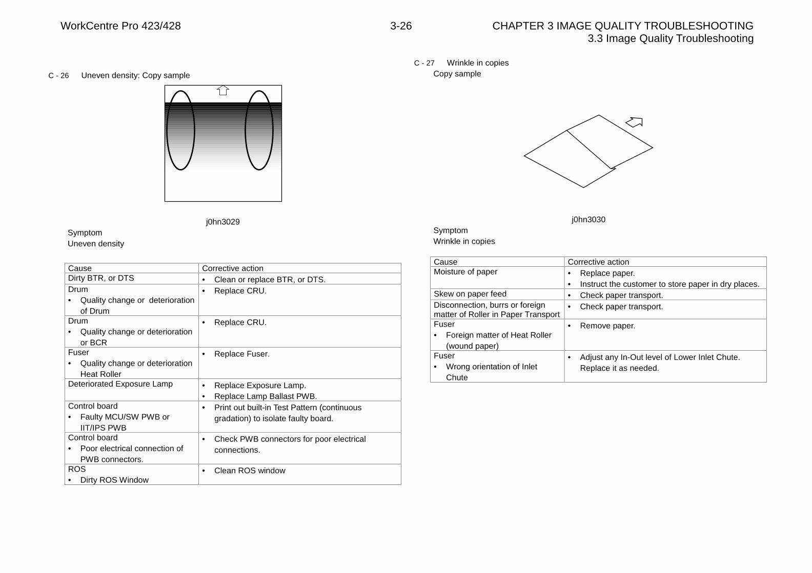
WorkCentre Pro 423/428 3-26 CHAPTER 3 IMAGE QUALITY TROUBLESHOOTING3.3 Image Quality Troubleshooting
C - 26 Uneven density: Copy sample
j0hn3029SymptomUneven density
Cause Corrective actionDirty BTR, or DTS • Clean or replace BTR, or DTS.Drum• Quality change or deterioration
of Drum
• Replace CRU.
Drum• Quality change or deterioration
or BCR
• Replace CRU.
Fuser• Quality change or deterioration
Heat Roller
• Replace Fuser.
Deteriorated Exposure Lamp • Replace Exposure Lamp.• Replace Lamp Ballast PWB.
Control board• Faulty MCU/SW PWB or
IIT/IPS PWB
• Print out built-in Test Pattern (continuousgradation) to isolate faulty board.
Control board• Poor electrical connection of
PWB connectors.
• Check PWB connectors for poor electricalconnections.
ROS• Dirty ROS Window
• Clean ROS window
C - 27 Wrinkle in copiesCopy sample
j0hn3030SymptomWrinkle in copies
Cause Corrective actionMoisture of paper • Replace paper.
• Instruct the customer to store paper in dry places.Skew on paper feed • Check paper transport.Disconnection, burrs or foreignmatter of Roller in Paper Transport
• Check paper transport.
Fuser• Foreign matter of Heat Roller
(wound paper)
• Remove paper.
Fuser• Wrong orientation of Inlet
Chute
• Adjust any In-Out level of Lower Inlet Chute.Replace it as needed.
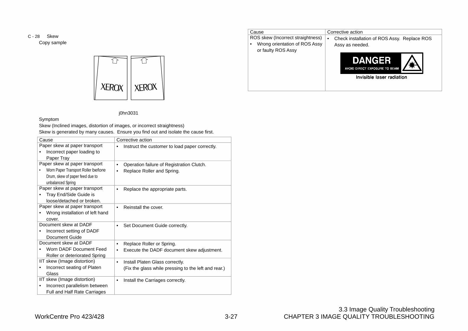
3.3 Image Quality TroubleshootingWorkCentre Pro 423/428 3-27 CHAPTER 3 IMAGE QUALITY TROUBLESHOOTING
C - 28 SkewCopy sample
j0hn3031SymptomSkew (Inclined images, distortion of images, or incorrect straightness)Skew is generated by many causes. Ensure you find out and isolate the cause first.
Cause Corrective actionPaper skew at paper transport• Incorrect paper loading to
Paper Tray
• Instruct the customer to load paper correctly.
Paper skew at paper transport• Worn Paper Transport Roller before
Drum, skew of paper feed due tounbalanced Spring
• Operation failure of Registration Clutch.• Replace Roller and Spring.
Paper skew at paper transport• Tray End/Side Guide is
loose/detached or broken.
• Replace the appropriate parts.
Paper skew at paper transport• Wrong installation of left hand
cover.
• Reinstall the cover.
Document skew at DADF• Incorrect setting of DADF
Document Guide
• Set Document Guide correctly.
Document skew at DADF• Worn DADF Document Feed
Roller or deteriorated Spring
• Replace Roller or Spring.• Execute the DADF document skew adjustment.
IIT skew (Image distortion)• Incorrect seating of Platen
Glass
• Install Platen Glass correctly.(Fix the glass while pressing to the left and rear.)
IIT skew (Image distortion)• Incorrect parallelism between
Full and Half Rate Carriages
• Install the Carriages correctly.
Cause Corrective actionROS skew (Incorrect straightness)• Wrong orientation of ROS Assy
or faulty ROS Assy
• Check installation of ROS Assy. Replace ROSAssy as needed.
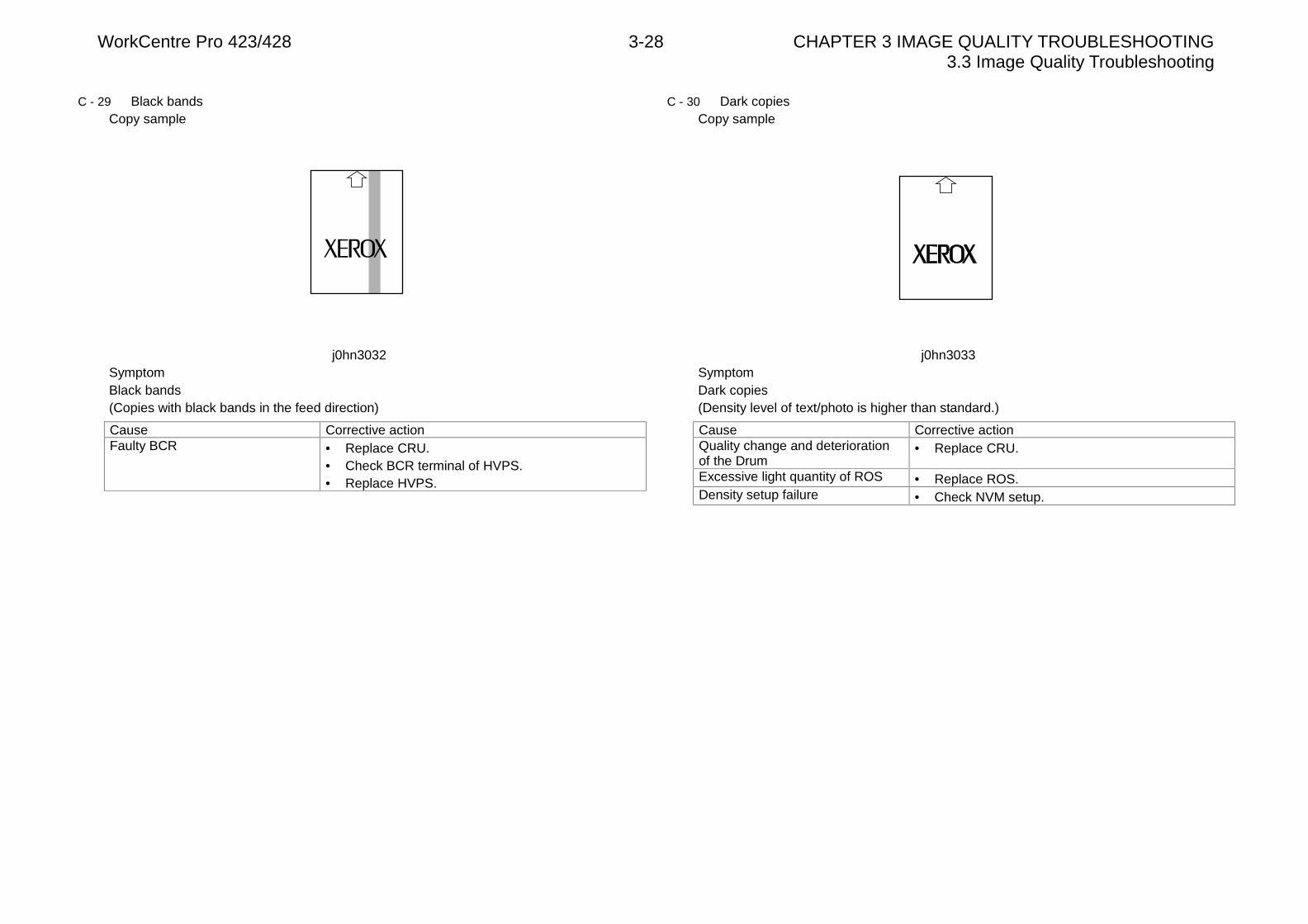
WorkCentre Pro 423/428 3-28 CHAPTER 3 IMAGE QUALITY TROUBLESHOOTING3.3 Image Quality Troubleshooting
C - 29 Black bandsCopy sample
j0hn3032SymptomBlack bands(Copies with black bands in the feed direction)
Cause Corrective actionFaulty BCR • Replace CRU.
• Check BCR terminal of HVPS.• Replace HVPS.
C - 30 Dark copiesCopy sample
j0hn3033SymptomDark copies(Density level of text/photo is higher than standard.)
Cause Corrective actionQuality change and deteriorationof the Drum
• Replace CRU.
Excessive light quantity of ROS • Replace ROS.Density setup failure • Check NVM setup.

CHAPTER 4 DISASSEMBLY/ASSEMBLY AND ADJUSTMENT

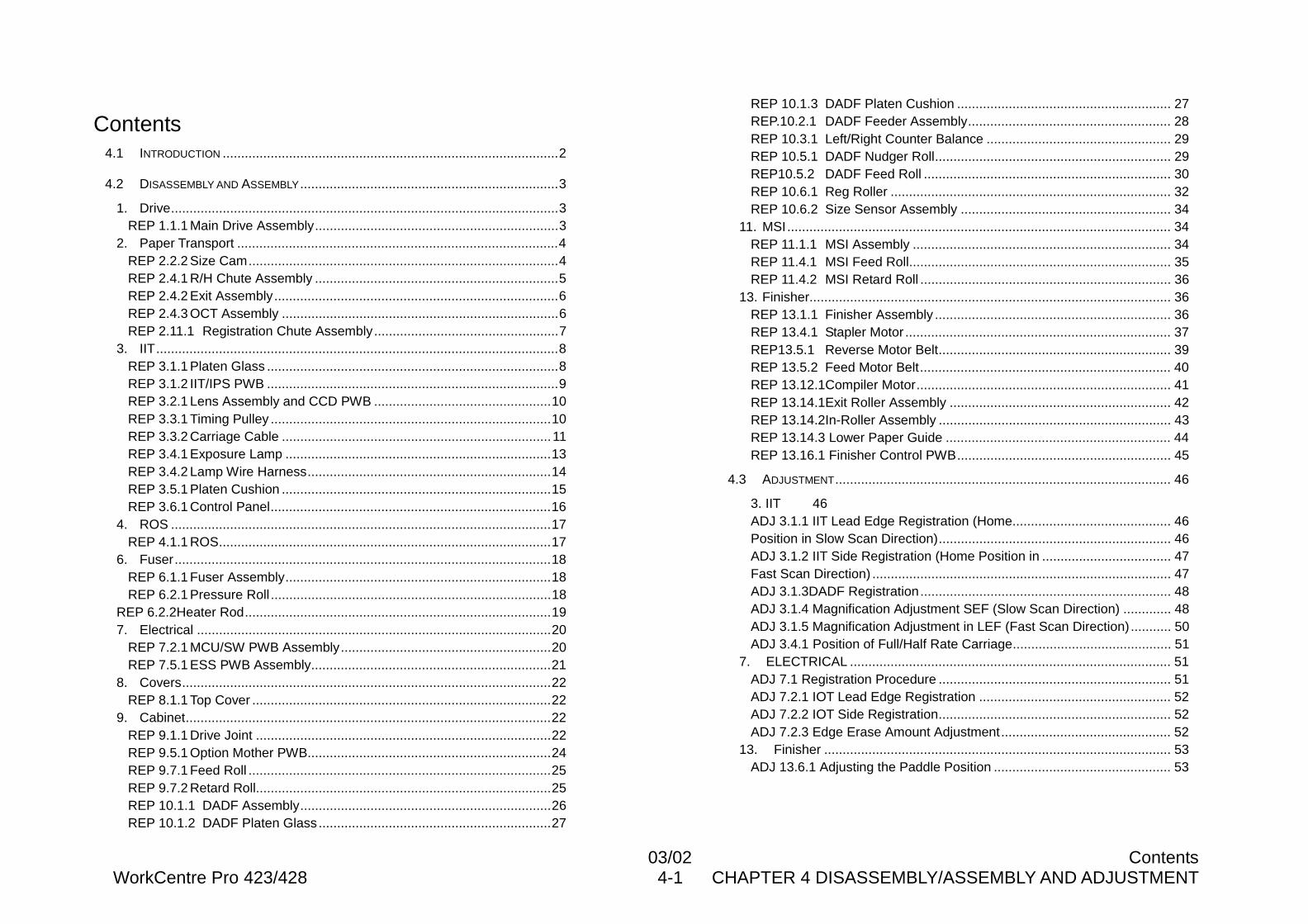
03/02 ContentsWorkCentre Pro 423/428 4-1 CHAPTER 4 DISASSEMBLY/ASSEMBLY AND ADJUSTMENT
Contents4.1 INTRODUCTION ...........................................................................................2
4.2 DISASSEMBLY AND ASSEMBLY......................................................................3
1. Drive.........................................................................................................3REP 1.1.1 Main Drive Assembly..................................................................3
2. Paper Transport .......................................................................................4REP 2.2.2 Size Cam....................................................................................4REP 2.4.1 R/H Chute Assembly ..................................................................5REP 2.4.2 Exit Assembly.............................................................................6REP 2.4.3 OCT Assembly ...........................................................................6REP 2.11.1 Registration Chute Assembly..................................................7
3. IIT.............................................................................................................8REP 3.1.1 Platen Glass ...............................................................................8REP 3.1.2 IIT/IPS PWB ...............................................................................9REP 3.2.1 Lens Assembly and CCD PWB ................................................10REP 3.3.1 Timing Pulley ............................................................................10REP 3.3.2 Carriage Cable .........................................................................11REP 3.4.1 Exposure Lamp ........................................................................13REP 3.4.2 Lamp Wire Harness..................................................................14REP 3.5.1 Platen Cushion .........................................................................15REP 3.6.1 Control Panel............................................................................16
4. ROS .......................................................................................................17REP 4.1.1 ROS..........................................................................................17
6. Fuser......................................................................................................18REP 6.1.1 Fuser Assembly........................................................................18REP 6.2.1 Pressure Roll ............................................................................18
REP 6.2.2Heater Rod...................................................................................197. Electrical ................................................................................................20
REP 7.2.1 MCU/SW PWB Assembly.........................................................20REP 7.5.1 ESS PWB Assembly.................................................................21
8. Covers....................................................................................................22REP 8.1.1 Top Cover .................................................................................22
9. Cabinet...................................................................................................22REP 9.1.1 Drive Joint ................................................................................22REP 9.5.1 Option Mother PWB..................................................................24REP 9.7.1 Feed Roll ..................................................................................25REP 9.7.2 Retard Roll................................................................................25REP 10.1.1 DADF Assembly....................................................................26REP 10.1.2 DADF Platen Glass ...............................................................27
REP 10.1.3 DADF Platen Cushion .......................................................... 27REP.10.2.1 DADF Feeder Assembly....................................................... 28REP 10.3.1 Left/Right Counter Balance .................................................. 29REP 10.5.1 DADF Nudger Roll................................................................ 29REP10.5.2 DADF Feed Roll ................................................................... 30REP 10.6.1 Reg Roller ............................................................................ 32REP 10.6.2 Size Sensor Assembly ......................................................... 34
11. MSI........................................................................................................ 34REP 11.1.1 MSI Assembly ...................................................................... 34REP 11.4.1 MSI Feed Roll....................................................................... 35REP 11.4.2 MSI Retard Roll .................................................................... 36
13. Finisher.................................................................................................. 36REP 13.1.1 Finisher Assembly ................................................................ 36REP 13.4.1 Stapler Motor ........................................................................ 37REP13.5.1 Reverse Motor Belt............................................................... 39REP 13.5.2 Feed Motor Belt.................................................................... 40REP 13.12.1Compiler Motor..................................................................... 41REP 13.14.1Exit Roller Assembly ............................................................ 42REP 13.14.2In-Roller Assembly ............................................................... 43REP 13.14.3 Lower Paper Guide ............................................................. 44REP 13.16.1 Finisher Control PWB.......................................................... 45
4.3 ADJUSTMENT........................................................................................... 46
3. IIT 46ADJ 3.1.1 IIT Lead Edge Registration (Home........................................... 46Position in Slow Scan Direction)............................................................... 46ADJ 3.1.2 IIT Side Registration (Home Position in ................................... 47Fast Scan Direction) ................................................................................. 47ADJ 3.1.3DADF Registration.................................................................... 48ADJ 3.1.4 Magnification Adjustment SEF (Slow Scan Direction) ............. 48ADJ 3.1.5 Magnification Adjustment in LEF (Fast Scan Direction) ........... 50ADJ 3.4.1 Position of Full/Half Rate Carriage........................................... 51
7. ELECTRICAL ....................................................................................... 51ADJ 7.1 Registration Procedure ............................................................... 51ADJ 7.2.1 IOT Lead Edge Registration .................................................... 52ADJ 7.2.2 IOT Side Registration............................................................... 52ADJ 7.2.3 Edge Erase Amount Adjustment.............................................. 52
13. Finisher .............................................................................................. 53ADJ 13.6.1 Adjusting the Paddle Position ................................................ 53
WorkCentre Pro 423/428 4-2 CHAPTER 4 DISASSEMBLY/ASSEMBLY AND ADJUSTMENT03/02 4.1 Introduction
4.1 Introduction
4.1.1 Using Disassembly, Assembly, and Adjustment
There are the following rules in the procedures fortaking field services, e.g., disassembly, assembly,replacement, and adjustment of parts.
1. [Subsystem] : It is divided into 13 subsystems,which are described in this manual. Eachsubsystem is further divided into sub-titles. Eachtitle has an item number that matches a platenumber shown in the parts list in Chapter 5. By thismethod, the user can easily find a target procedurefrom the parts list and vice versa.[Example]Disassembly, Assembly, and Adjustment: 1.1.1 Main Drive Motor AssemblyParts List: PL1.1 Main Drive Motor
2. [Figure -1]: Figure-1” at the end of sentencesindicates that the detailed procedure is the workprocedure in the illustration. The illustration showsthe symmetric parts on the left and right only withthe ones in either side.
3. [Installation]: Describes only a comment becausethe installation procedure is the reverse of theremoval procedure.
4. [Replacement Procedure]: The replacementprocedure is omitted when it is easy without theremoval and installation procedures; however, onlya comment is described if the related adjustment isrequired.
5. [Reference Procedure]:”REP or ADJ 2.1.3”following the procedure indicates a disassembly,assembly, or adjustment item to be referenced.
6. [Prerequisites]: Be sure to confirm the prerequisiteslisted as notes before the procedure.
7. [Modification]: A modification number is shownbefore the title or procedure for which a differenceis between the preceding and modified contents.
[Example 1]x.x.x “A” Roller [5V executed]* Indicates that all the procedures indicated by this
title apply to a 5V-executed machine.
[Example 2]2. [3V unexecuted]: Remove the “B”Roller.* Indicates that procedure 2 applies only to a 3V-
unexecuted machine.
[Example 3]Figure -1 [3V executed]* Indicates that the reference diagram of Figure-1
belongs to a 3V-executed machine.
[Example 4]This symbol indicates the contentsthat are modified by the modificationexpressed with a number in thesymbol.
This symbol indicates the contentsthat are not yet modified with themodification expressed with anumber in the symbol.
8. [Machine direction name]: Defines the position anddirection used in each procedure and directions inthe machine as follows:• Front: Front of machine• Right: Right, taking a front view of the machine• Left : Left, taking a front view of the machine• Rear : Rear, taking a front view of the machine
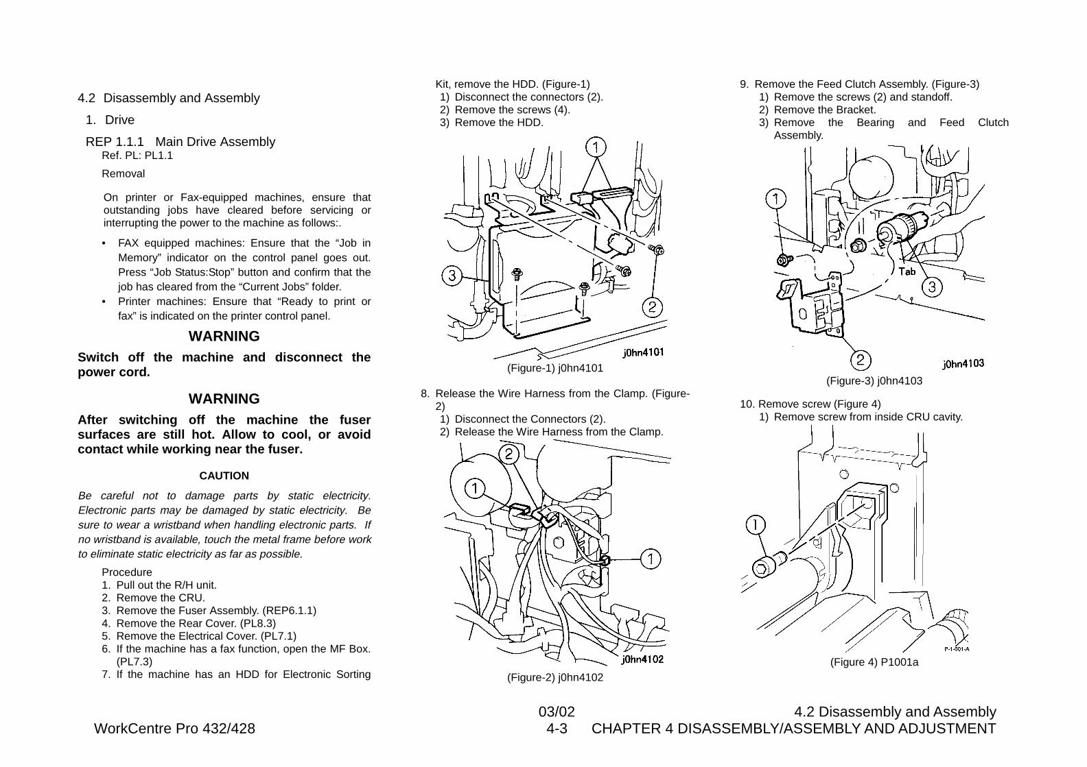
03/02 4.2 Disassembly and AssemblyWorkCentre Pro 432/428 4-3 CHAPTER 4 DISASSEMBLY/ASSEMBLY AND ADJUSTMENT
4.2 Disassembly and Assembly
1. Drive
REP 1.1.1 Main Drive AssemblyRef. PL: PL1.1
Removal
On printer or Fax-equipped machines, ensure thatoutstanding jobs have cleared before servicing orinterrupting the power to the machine as follows:.
• FAX equipped machines: Ensure that the “Job inMemory” indicator on the control panel goes out.Press “Job Status:Stop” button and confirm that thejob has cleared from the “Current Jobs” folder.
• Printer machines: Ensure that “Ready to print orfax” is indicated on the printer control panel.
WARNINGSwitch off the machine and disconnect thepower cord.
WARNINGAfter switching off the machine the fusersurfaces are still hot. Allow to cool, or avoidcontact while working near the fuser.
CAUTION
Be careful not to damage parts by static electricity.Electronic parts may be damaged by static electricity. Besure to wear a wristband when handling electronic parts. Ifno wristband is available, touch the metal frame before workto eliminate static electricity as far as possible.
Procedure1. Pull out the R/H unit.2. Remove the CRU.3. Remove the Fuser Assembly. (REP6.1.1)4. Remove the Rear Cover. (PL8.3)5. Remove the Electrical Cover. (PL7.1)6. If the machine has a fax function, open the MF Box.
(PL7.3)7. If the machine has an HDD for Electronic Sorting
Kit, remove the HDD. (Figure-1)1) Disconnect the connectors (2).2) Remove the screws (4).3) Remove the HDD.
(Figure-1) j0hn4101
8. Release the Wire Harness from the Clamp. (Figure-2)1) Disconnect the Connectors (2).2) Release the Wire Harness from the Clamp.
(Figure-2) j0hn4102
9. Remove the Feed Clutch Assembly. (Figure-3)1) Remove the screws (2) and standoff.2) Remove the Bracket.3) Remove the Bearing and Feed Clutch
Assembly.
(Figure-3) j0hn4103
10. Remove screw (Figure 4)1) Remove screw from inside CRU cavity.
(Figure 4) P1001a
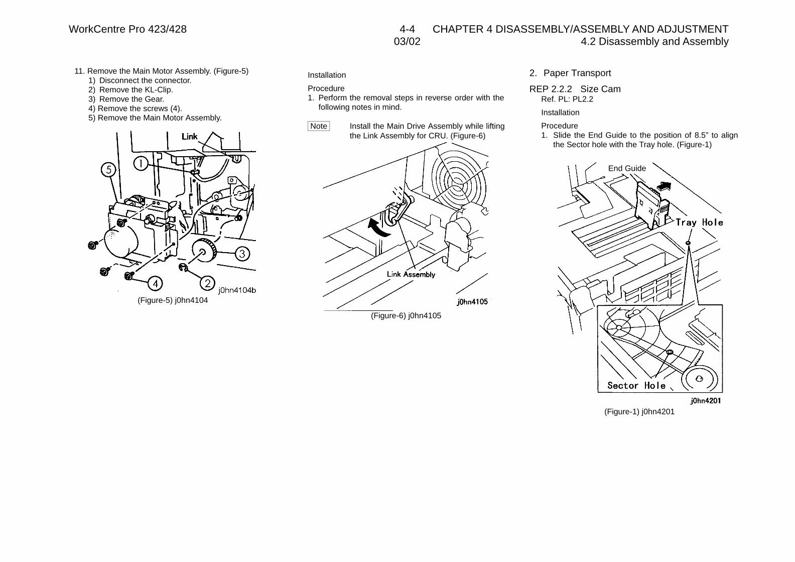
WorkCentre Pro 423/428 4-4 CHAPTER 4 DISASSEMBLY/ASSEMBLY AND ADJUSTMENT03/02 4.2 Disassembly and Assembly
11. Remove the Main Motor Assembly. (Figure-5)1) Disconnect the connector.2) Remove the KL-Clip.3) Remove the Gear.4) Remove the screws (4).5) Remove the Main Motor Assembly.
(Figure-5) j0hn4104
Installation
Procedure1. Perform the removal steps in reverse order with the
following notes in mind.
Note Install the Main Drive Assembly while liftingthe Link Assembly for CRU. (Figure-6)
(Figure-6) j0hn4105
2. Paper Transport
REP 2.2.2 Size CamRef. PL: PL2.2
Installation
Procedure1. Slide the End Guide to the position of 8.5” to align
the Sector hole with the Tray hole. (Figure-1)
(Figure-1) j0hn4201
End Guide
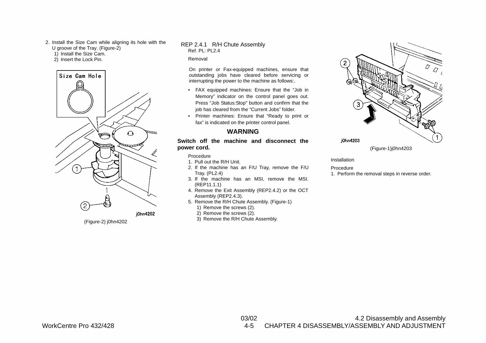
03/02 4.2 Disassembly and AssemblyWorkCentre Pro 432/428 4-5 CHAPTER 4 DISASSEMBLY/ASSEMBLY AND ADJUSTMENT
2. Install the Size Cam while aligning its hole with theU groove of the Tray. (Figure-2)1) Install the Size Cam.2) Insert the Lock Pin.
(Figure-2) j0hn4202
REP 2.4.1 R/H Chute AssemblyRef. PL: PL2.4
Removal
On printer or Fax-equipped machines, ensure thatoutstanding jobs have cleared before servicing orinterrupting the power to the machine as follows:.
• FAX equipped machines: Ensure that the “Job inMemory” indicator on the control panel goes out.Press “Job Status:Stop” button and confirm that thejob has cleared from the “Current Jobs” folder.
• Printer machines: Ensure that “Ready to print orfax” is indicated on the printer control panel.
WARNINGSwitch off the machine and disconnect thepower cord.
Procedure1. Pull out the R/H Unit.2. If the machine has an F/U Tray, remove the F/U
Tray. (PL2.4)3. If the machine has an MSI, remove the MSI.
(REP11.1.1)4. Remove the Exit Assembly (REP2.4.2) or the OCT
Assembly (REP2.4.3).5. Remove the R/H Chute Assembly. (Figure-1)
1) Remove the screws (2).2) Remove the screws (2).3) Remove the R/H Chute Assembly.
(Figure-1)j0hn4203
Installation
Procedure1. Perform the removal steps in reverse order.
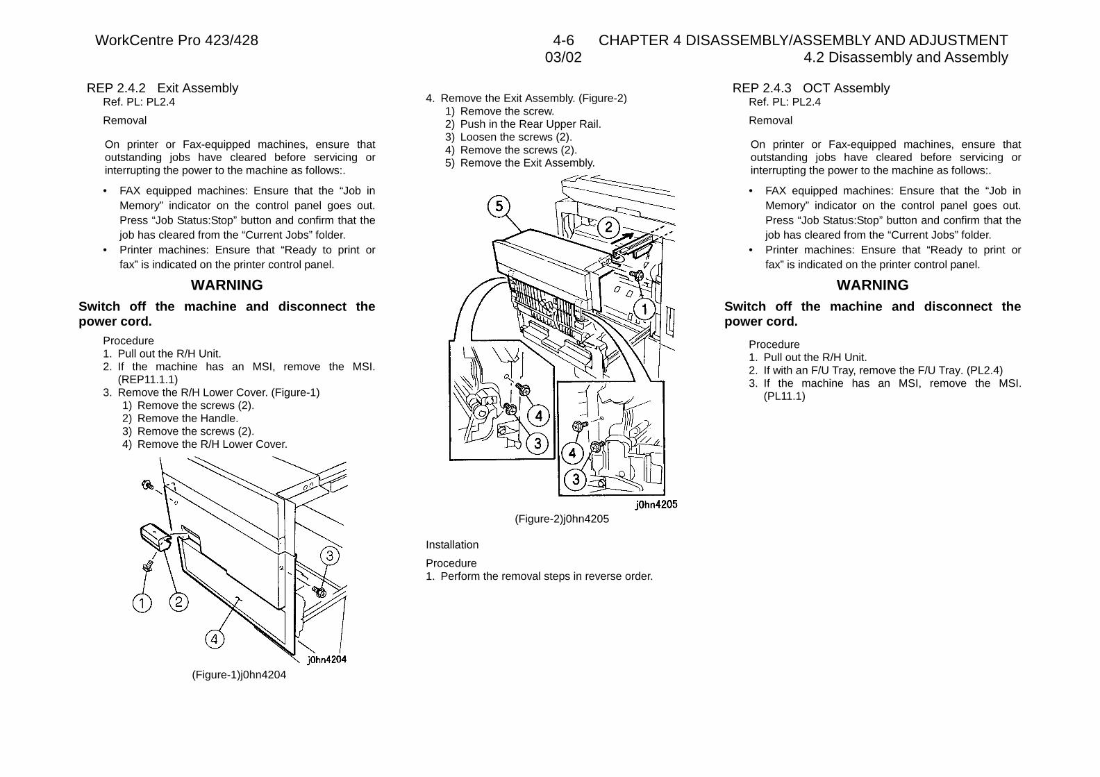
WorkCentre Pro 423/428 4-6 CHAPTER 4 DISASSEMBLY/ASSEMBLY AND ADJUSTMENT03/02 4.2 Disassembly and Assembly
REP 2.4.2 Exit AssemblyRef. PL: PL2.4
Removal
On printer or Fax-equipped machines, ensure thatoutstanding jobs have cleared before servicing orinterrupting the power to the machine as follows:.
• FAX equipped machines: Ensure that the “Job inMemory” indicator on the control panel goes out.Press “Job Status:Stop” button and confirm that thejob has cleared from the “Current Jobs” folder.
• Printer machines: Ensure that “Ready to print orfax” is indicated on the printer control panel.
WARNINGSwitch off the machine and disconnect thepower cord.
Procedure1. Pull out the R/H Unit.2. If the machine has an MSI, remove the MSI.
(REP11.1.1)3. Remove the R/H Lower Cover. (Figure-1)
1) Remove the screws (2).2) Remove the Handle.3) Remove the screws (2).4) Remove the R/H Lower Cover.
(Figure-1)j0hn4204
4. Remove the Exit Assembly. (Figure-2)1) Remove the screw.2) Push in the Rear Upper Rail.3) Loosen the screws (2).4) Remove the screws (2).5) Remove the Exit Assembly.
(Figure-2)j0hn4205
Installation
Procedure1. Perform the removal steps in reverse order.
REP 2.4.3 OCT AssemblyRef. PL: PL2.4
Removal
On printer or Fax-equipped machines, ensure thatoutstanding jobs have cleared before servicing orinterrupting the power to the machine as follows:.
• FAX equipped machines: Ensure that the “Job inMemory” indicator on the control panel goes out.Press “Job Status:Stop” button and confirm that thejob has cleared from the “Current Jobs” folder.
• Printer machines: Ensure that “Ready to print orfax” is indicated on the printer control panel.
WARNINGSwitch off the machine and disconnect thepower cord.
Procedure1. Pull out the R/H Unit.2. If with an F/U Tray, remove the F/U Tray. (PL2.4)3. If the machine has an MSI, remove the MSI.
(PL11.1)
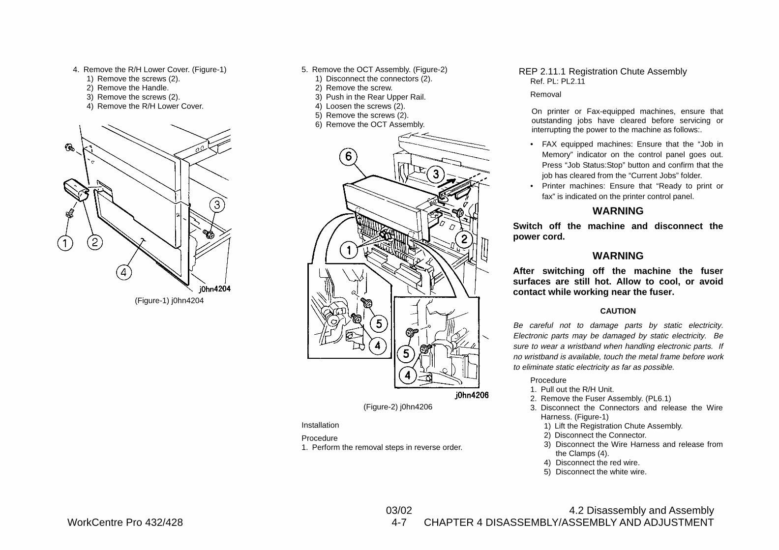
03/02 4.2 Disassembly and AssemblyWorkCentre Pro 432/428 4-7 CHAPTER 4 DISASSEMBLY/ASSEMBLY AND ADJUSTMENT
4. Remove the R/H Lower Cover. (Figure-1)1) Remove the screws (2).2) Remove the Handle.3) Remove the screws (2).4) Remove the R/H Lower Cover.
(Figure-1) j0hn4204
5. Remove the OCT Assembly. (Figure-2)1) Disconnect the connectors (2).2) Remove the screw.3) Push in the Rear Upper Rail.4) Loosen the screws (2).5) Remove the screws (2).6) Remove the OCT Assembly.
(Figure-2) j0hn4206
Installation
Procedure1. Perform the removal steps in reverse order.
REP 2.11.1 Registration Chute AssemblyRef. PL: PL2.11
Removal
On printer or Fax-equipped machines, ensure thatoutstanding jobs have cleared before servicing orinterrupting the power to the machine as follows:.
• FAX equipped machines: Ensure that the “Job inMemory” indicator on the control panel goes out.Press “Job Status:Stop” button and confirm that thejob has cleared from the “Current Jobs” folder.
• Printer machines: Ensure that “Ready to print orfax” is indicated on the printer control panel.
WARNINGSwitch off the machine and disconnect thepower cord.
WARNINGAfter switching off the machine the fusersurfaces are still hot. Allow to cool, or avoidcontact while working near the fuser.
CAUTION
Be careful not to damage parts by static electricity.Electronic parts may be damaged by static electricity. Besure to wear a wristband when handling electronic parts. Ifno wristband is available, touch the metal frame before workto eliminate static electricity as far as possible.
Procedure1. Pull out the R/H Unit.2. Remove the Fuser Assembly. (PL6.1)3. Disconnect the Connectors and release the Wire
Harness. (Figure-1)1) Lift the Registration Chute Assembly.2) Disconnect the Connector.3) Disconnect the Wire Harness and release from
the Clamps (4).4) Disconnect the red wire.5) Disconnect the white wire.
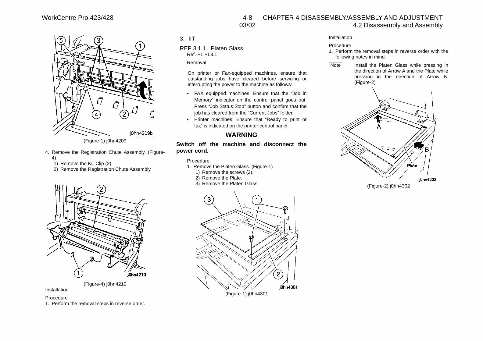
WorkCentre Pro 423/428 4-8 CHAPTER 4 DISASSEMBLY/ASSEMBLY AND ADJUSTMENT03/02 4.2 Disassembly and Assembly
(Figure-1) j0hn4209
4. Remove the Registration Chute Assembly. (Figure-4)1) Remove the KL-Clip (2).2) Remove the Registration Chute Assembly.
(Figure-4) j0hn4210Installation
Procedure1. Perform the removal steps in reverse order.
3. IIT
REP 3.1.1 Platen GlassRef. PL PL3.1
Removal
On printer or Fax-equipped machines, ensure thatoutstanding jobs have cleared before servicing orinterrupting the power to the machine as follows:.
• FAX equipped machines: Ensure that the “Job inMemory” indicator on the control panel goes out.Press “Job Status:Stop” button and confirm that thejob has cleared from the “Current Jobs” folder.
• Printer machines: Ensure that “Ready to print orfax” is indicated on the printer control panel.
WARNINGSwitch off the machine and disconnect thepower cord.
Procedure1. Remove the Platen Glass. (Figure-1)
1) Remove the screws (2).2) Remove the Plate.3) Remove the Platen Glass.
(Figure-1) j0hn4301
Installation
Procedure1. Perform the removal steps in reverse order with the
following notes in mind.
Note Install the Platen Glass while pressing inthe direction of Arrow A and the Plate whilepressing in the direction of Arrow B.(Figure-2)
(Figure-2) j0hn4302
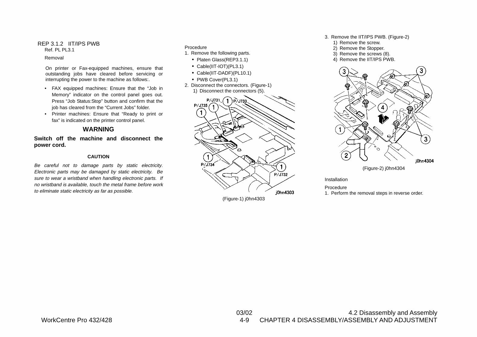
03/02 4.2 Disassembly and AssemblyWorkCentre Pro 432/428 4-9 CHAPTER 4 DISASSEMBLY/ASSEMBLY AND ADJUSTMENT
REP 3.1.2 IIT/IPS PWBRef. PL PL3.1
Removal
On printer or Fax-equipped machines, ensure thatoutstanding jobs have cleared before servicing orinterrupting the power to the machine as follows:.
• FAX equipped machines: Ensure that the “Job inMemory” indicator on the control panel goes out.Press “Job Status:Stop” button and confirm that thejob has cleared from the “Current Jobs” folder.
• Printer machines: Ensure that “Ready to print orfax” is indicated on the printer control panel.
WARNINGSwitch off the machine and disconnect thepower cord.
CAUTION
Be careful not to damage parts by static electricity.Electronic parts may be damaged by static electricity. Besure to wear a wristband when handling electronic parts. Ifno wristband is available, touch the metal frame before workto eliminate static electricity as far as possible.
Procedure1. Remove the following parts.
• Platen Glass(REP3.1.1)• Cable(IIT-IOT)(PL3.1)• Cable(IIT-DADF)(PL10.1)• PWB Cover(PL3.1)
2. Disconnect the connectors. (Figure-1)1) Disconnect the connectors (5).
(Figure-1) j0hn4303
3. Remove the IIT/IPS PWB. (Figure-2)1) Remove the screw.2) Remove the Stopper.3) Remove the screws (8).4) Remove the IIT/IPS PWB.
(Figure-2) j0hn4304
Installation
Procedure1. Perform the removal steps in reverse order.
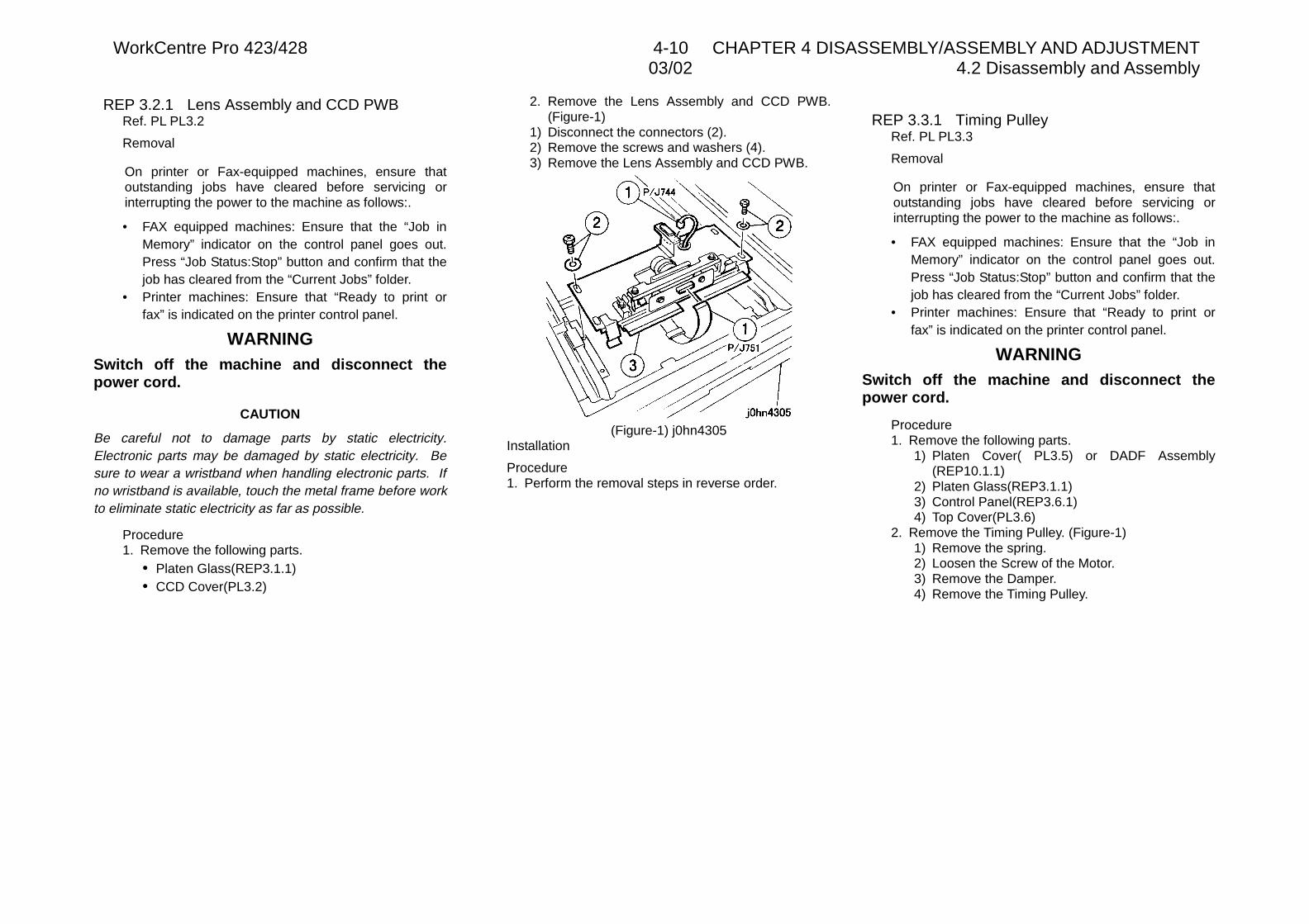
WorkCentre Pro 423/428 4-10 CHAPTER 4 DISASSEMBLY/ASSEMBLY AND ADJUSTMENT03/02 4.2 Disassembly and Assembly
REP 3.2.1 Lens Assembly and CCD PWBRef. PL PL3.2
Removal
On printer or Fax-equipped machines, ensure thatoutstanding jobs have cleared before servicing orinterrupting the power to the machine as follows:.
• FAX equipped machines: Ensure that the “Job inMemory” indicator on the control panel goes out.Press “Job Status:Stop” button and confirm that thejob has cleared from the “Current Jobs” folder.
• Printer machines: Ensure that “Ready to print orfax” is indicated on the printer control panel.
WARNINGSwitch off the machine and disconnect thepower cord.
CAUTION
Be careful not to damage parts by static electricity.Electronic parts may be damaged by static electricity. Besure to wear a wristband when handling electronic parts. Ifno wristband is available, touch the metal frame before workto eliminate static electricity as far as possible.
Procedure1. Remove the following parts.
• Platen Glass(REP3.1.1)• CCD Cover(PL3.2)
2. Remove the Lens Assembly and CCD PWB.(Figure-1)
1) Disconnect the connectors (2).2) Remove the screws and washers (4).3) Remove the Lens Assembly and CCD PWB.
(Figure-1) j0hn4305Installation
Procedure1. Perform the removal steps in reverse order.
REP 3.3.1 Timing PulleyRef. PL PL3.3
Removal
On printer or Fax-equipped machines, ensure thatoutstanding jobs have cleared before servicing orinterrupting the power to the machine as follows:.
• FAX equipped machines: Ensure that the “Job inMemory” indicator on the control panel goes out.Press “Job Status:Stop” button and confirm that thejob has cleared from the “Current Jobs” folder.
• Printer machines: Ensure that “Ready to print orfax” is indicated on the printer control panel.
WARNINGSwitch off the machine and disconnect thepower cord.
Procedure1. Remove the following parts.
1) Platen Cover( PL3.5) or DADF Assembly(REP10.1.1)
2) Platen Glass(REP3.1.1)3) Control Panel(REP3.6.1)4) Top Cover(PL3.6)
2. Remove the Timing Pulley. (Figure-1)1) Remove the spring.2) Loosen the Screw of the Motor.3) Remove the Damper.4) Remove the Timing Pulley.
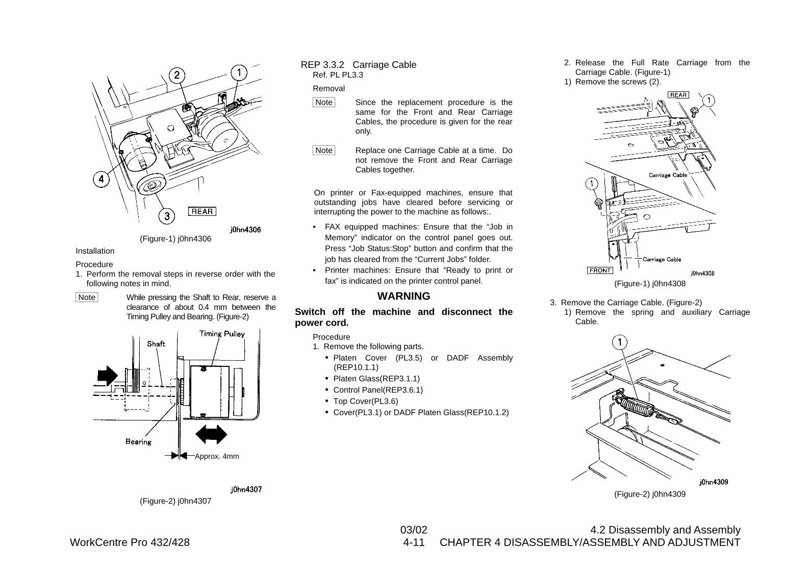
03/02 4.2 Disassembly and AssemblyWorkCentre Pro 432/428 4-11 CHAPTER 4 DISASSEMBLY/ASSEMBLY AND ADJUSTMENT
(Figure-1) j0hn4306
Installation
Procedure1. Perform the removal steps in reverse order with the
following notes in mind.
Note While pressing the Shaft to Rear, reserve aclearance of about 0.4 mm between theTiming Pulley and Bearing. (Figure-2)
(Figure-2) j0hn4307
REP 3.3.2 Carriage CableRef. PL PL3.3
Removal
Note Since the replacement procedure is thesame for the Front and Rear CarriageCables, the procedure is given for the rearonly.
Note Replace one Carriage Cable at a time. Donot remove the Front and Rear CarriageCables together.
On printer or Fax-equipped machines, ensure thatoutstanding jobs have cleared before servicing orinterrupting the power to the machine as follows:.
• FAX equipped machines: Ensure that the “Job inMemory” indicator on the control panel goes out.Press “Job Status:Stop” button and confirm that thejob has cleared from the “Current Jobs” folder.
• Printer machines: Ensure that “Ready to print orfax” is indicated on the printer control panel.
WARNINGSwitch off the machine and disconnect thepower cord.
Procedure1. Remove the following parts.
• Platen Cover (PL3.5) or DADF Assembly(REP10.1.1)
• Platen Glass(REP3.1.1)• Control Panel(REP3.6.1)• Top Cover(PL3.6)• Cover(PL3.1) or DADF Platen Glass(REP10.1.2)
2. Release the Full Rate Carriage from theCarriage Cable. (Figure-1)
1) Remove the screws (2).
(Figure-1) j0hn4308
3. Remove the Carriage Cable. (Figure-2)1) Remove the spring and auxiliary Carriage
Cable.
(Figure-2) j0hn4309
Approx. 4mm
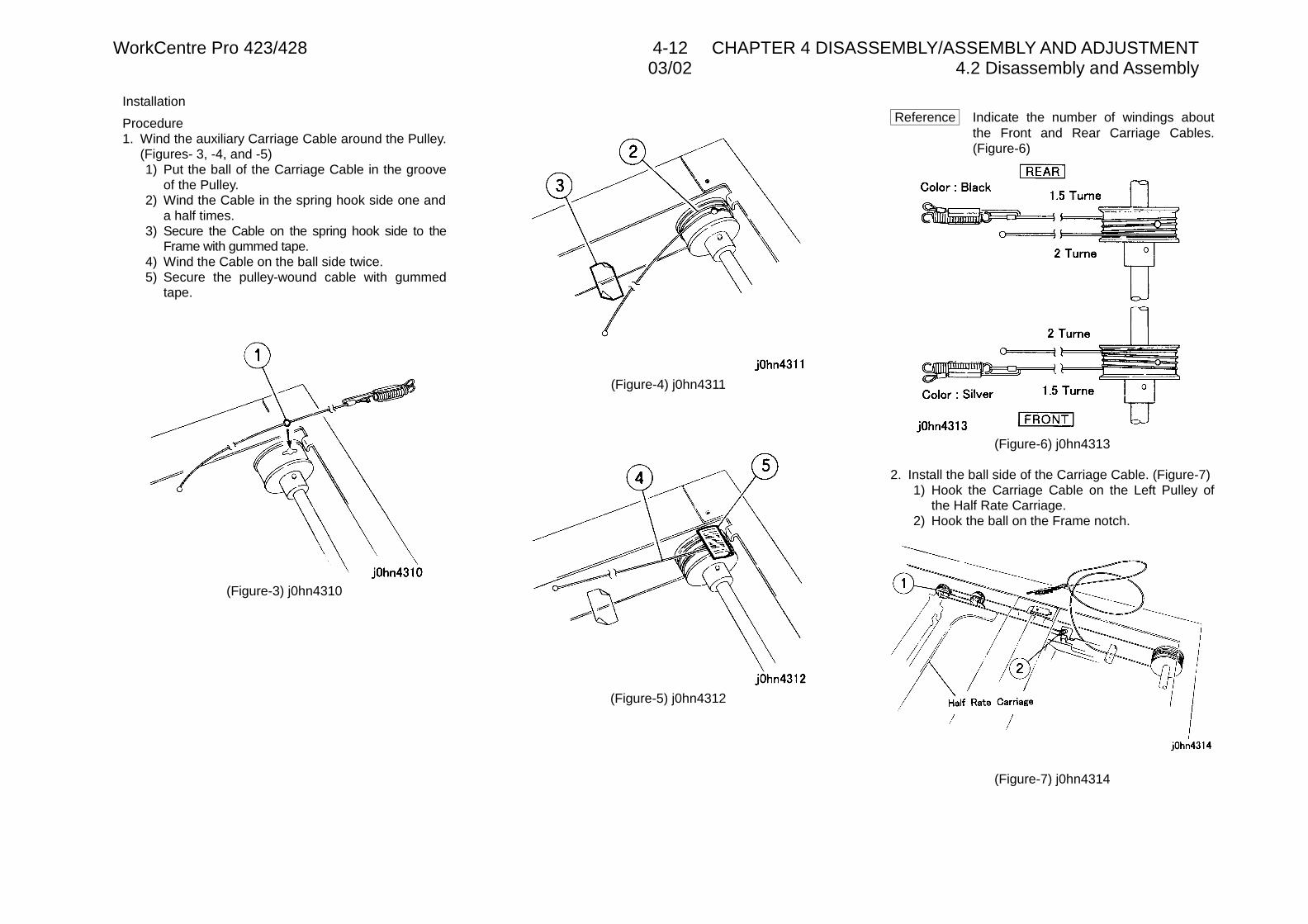
WorkCentre Pro 423/428 4-12 CHAPTER 4 DISASSEMBLY/ASSEMBLY AND ADJUSTMENT03/02 4.2 Disassembly and Assembly
Installation
Procedure1. Wind the auxiliary Carriage Cable around the Pulley.
(Figures- 3, -4, and -5)1) Put the ball of the Carriage Cable in the groove
of the Pulley.2) Wind the Cable in the spring hook side one and
a half times.3) Secure the Cable on the spring hook side to the
Frame with gummed tape.4) Wind the Cable on the ball side twice.5) Secure the pulley-wound cable with gummed
tape.
(Figure-3) j0hn4310
(Figure-4) j0hn4311
(Figure-5) j0hn4312
Reference Indicate the number of windings aboutthe Front and Rear Carriage Cables.(Figure-6)
(Figure-6) j0hn4313
2. Install the ball side of the Carriage Cable. (Figure-7)1) Hook the Carriage Cable on the Left Pulley of
the Half Rate Carriage.2) Hook the ball on the Frame notch.
(Figure-7) j0hn4314

03/02 4.2 Disassembly and AssemblyWorkCentre Pro 432/428 4-13 CHAPTER 4 DISASSEMBLY/ASSEMBLY AND ADJUSTMENT
3. Install the spring hook side of the Carriage Cable.(Figure-8)1) Hook the Cable on the Frame Pulley.2) Hook the Cable on the Right Pulley of the Half
Rate Carriage.3) Hook the spring and auxiliary Cable on the
Frame Hook.4) Secure the Full Rate Carriage on the Cable
temporarily.
(Figure-8) j0hn4315
Reference The Front Carriage Cable is routed asshown here. (Figure-9)
1) Secure the Full Rate Carriage Cable on theCable temporarily.
(Figure-9) j0hn4316
4. Peel off the gummed tape securing the Cable.5. Adjust the position and parallelism of Full Rate/Half
Rate Carriage. (ADJ 3.4.1)6. Move the Full Rate Carriage by hand to check its
smooth movement.
REP 3.4.1 Exposure LampRef. PL PL3.4
Removal
On printer or Fax-equipped machines, ensure thatoutstanding jobs have cleared before servicing orinterrupting the power to the machine as follows:.
• FAX equipped machines: Ensure that the “Job inMemory” indicator on the control panel goes out.Press “Job Status:Stop” button and confirm that thejob has cleared from the “Current Jobs” folder.
• Printer machines: Ensure that “Ready to print orfax” is indicated on the printer control panel.
WARNINGSwitch off the machine and disconnect thepower cord.
Procedure1. Remove the Platen Glass. (REP3.1.1)
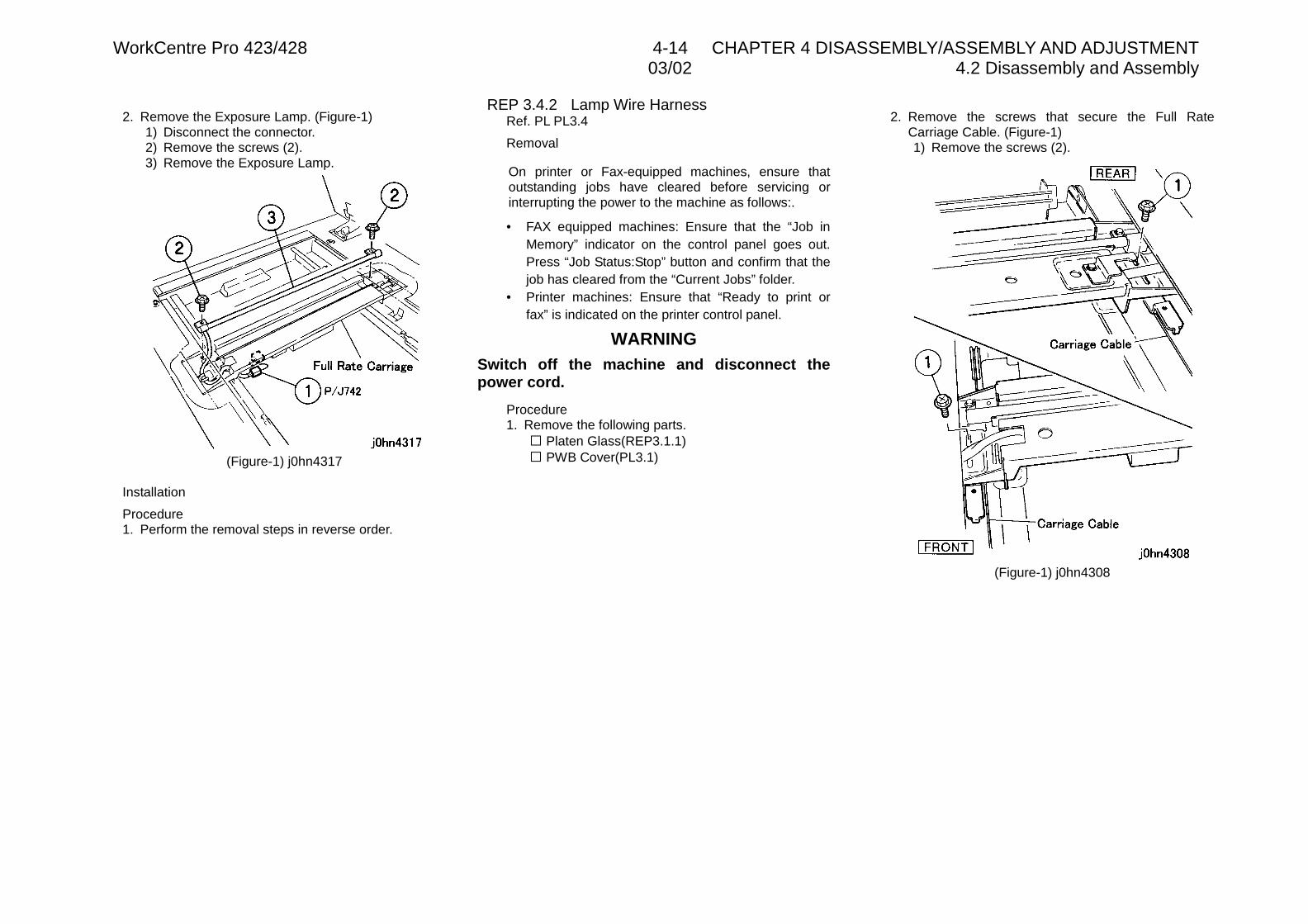
WorkCentre Pro 423/428 4-14 CHAPTER 4 DISASSEMBLY/ASSEMBLY AND ADJUSTMENT03/02 4.2 Disassembly and Assembly
2. Remove the Exposure Lamp. (Figure-1)1) Disconnect the connector.2) Remove the screws (2).3) Remove the Exposure Lamp.
(Figure-1) j0hn4317
Installation
Procedure1. Perform the removal steps in reverse order.
REP 3.4.2 Lamp Wire HarnessRef. PL PL3.4
Removal
On printer or Fax-equipped machines, ensure thatoutstanding jobs have cleared before servicing orinterrupting the power to the machine as follows:.
• FAX equipped machines: Ensure that the “Job inMemory” indicator on the control panel goes out.Press “Job Status:Stop” button and confirm that thejob has cleared from the “Current Jobs” folder.
• Printer machines: Ensure that “Ready to print orfax” is indicated on the printer control panel.
WARNINGSwitch off the machine and disconnect thepower cord.
Procedure1. Remove the following parts.
� Platen Glass(REP3.1.1)� PWB Cover(PL3.1)
2. Remove the screws that secure the Full RateCarriage Cable. (Figure-1)1) Remove the screws (2).
(Figure-1) j0hn4308
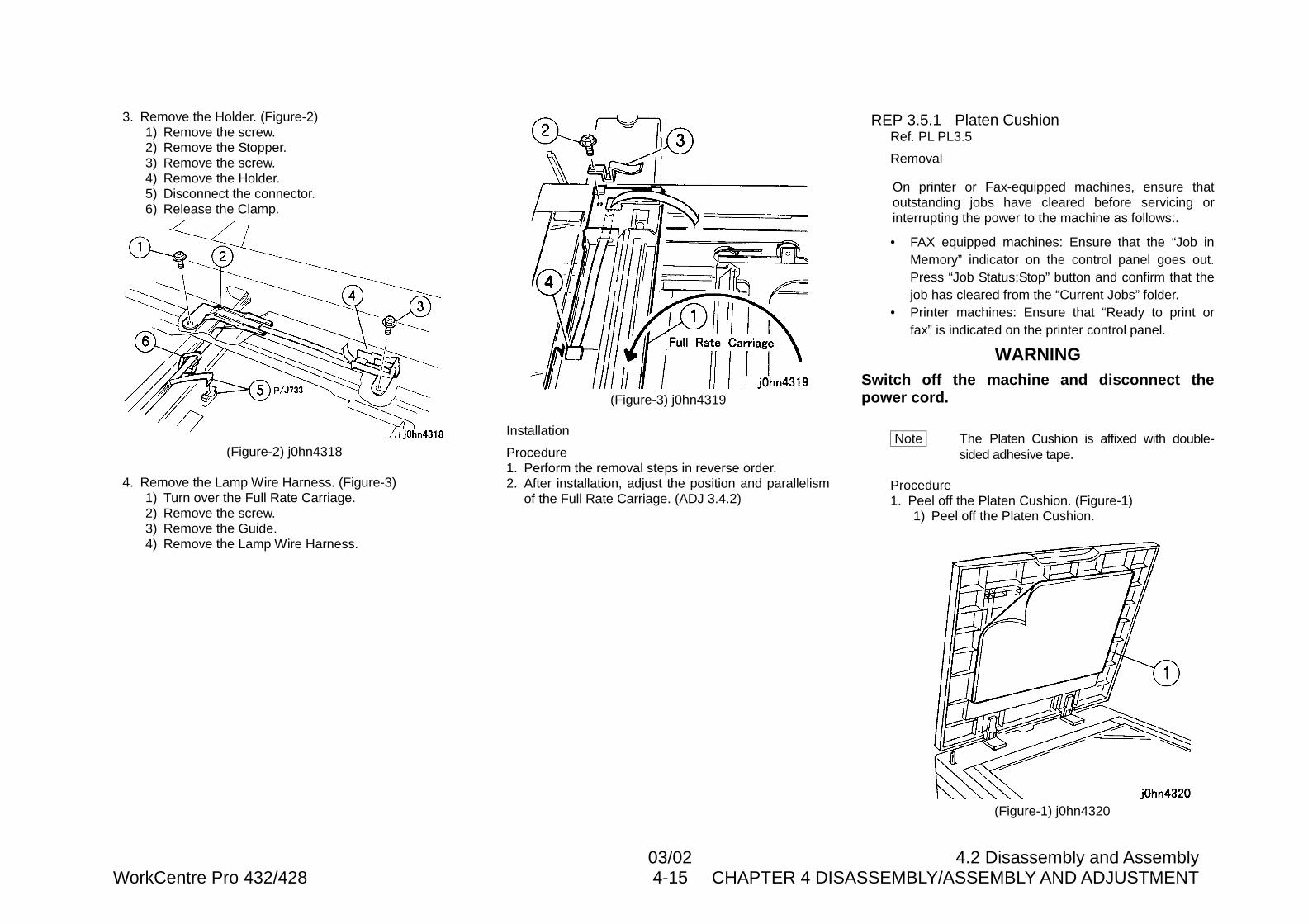
03/02 4.2 Disassembly and AssemblyWorkCentre Pro 432/428 4-15 CHAPTER 4 DISASSEMBLY/ASSEMBLY AND ADJUSTMENT
3. Remove the Holder. (Figure-2)1) Remove the screw.2) Remove the Stopper.3) Remove the screw.4) Remove the Holder.5) Disconnect the connector.6) Release the Clamp.
(Figure-2) j0hn4318
4. Remove the Lamp Wire Harness. (Figure-3)1) Turn over the Full Rate Carriage.2) Remove the screw.3) Remove the Guide.4) Remove the Lamp Wire Harness.
(Figure-3) j0hn4319
Installation
Procedure1. Perform the removal steps in reverse order.2. After installation, adjust the position and parallelism
of the Full Rate Carriage. (ADJ 3.4.2)
REP 3.5.1 Platen CushionRef. PL PL3.5
Removal
On printer or Fax-equipped machines, ensure thatoutstanding jobs have cleared before servicing orinterrupting the power to the machine as follows:.
• FAX equipped machines: Ensure that the “Job inMemory” indicator on the control panel goes out.Press “Job Status:Stop” button and confirm that thejob has cleared from the “Current Jobs” folder.
• Printer machines: Ensure that “Ready to print orfax” is indicated on the printer control panel.
WARNINGSwitch off the machine and disconnect thepower cord.
Note The Platen Cushion is affixed with double-sided adhesive tape.
Procedure1. Peel off the Platen Cushion. (Figure-1)
1) Peel off the Platen Cushion.
(Figure-1) j0hn4320
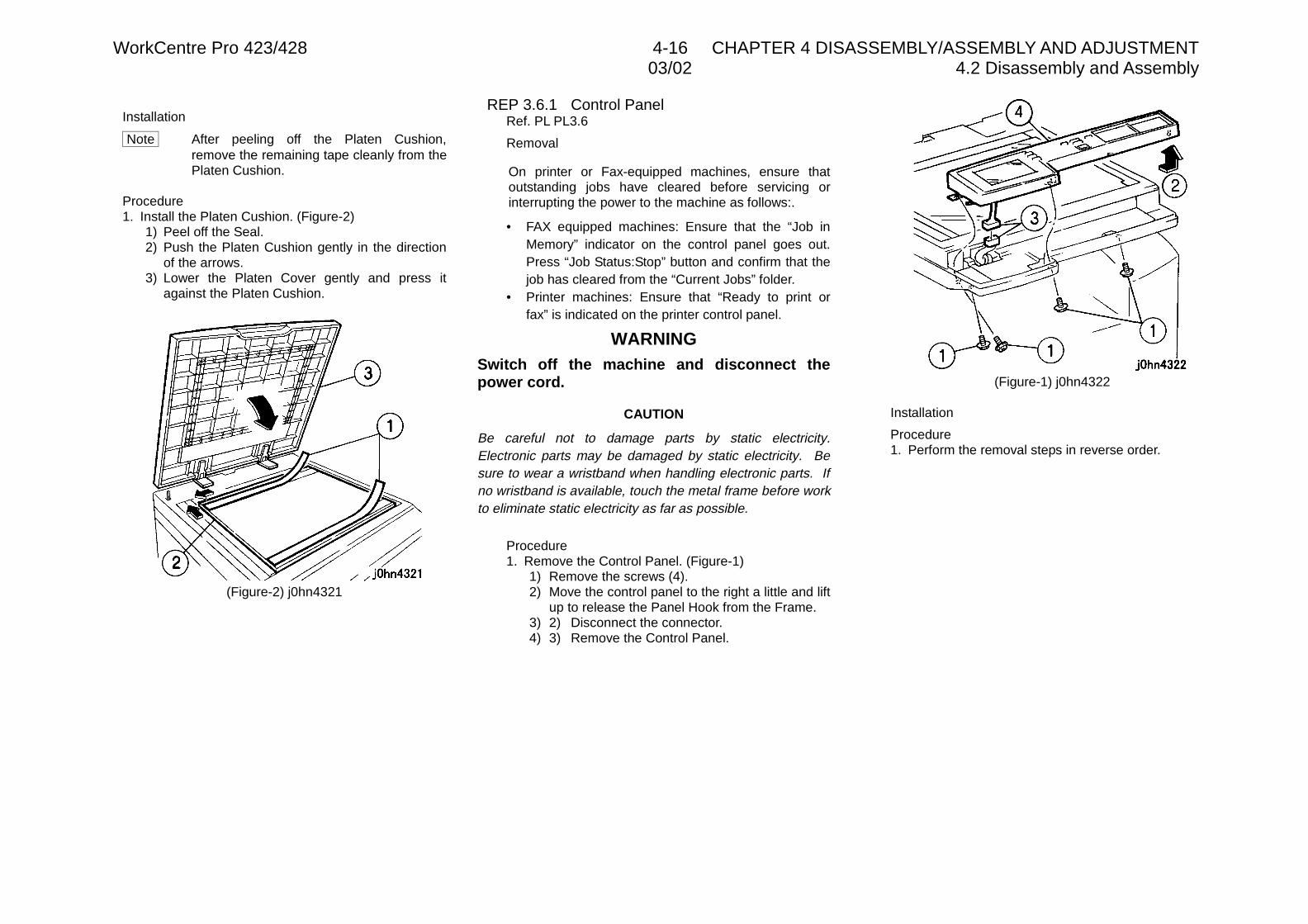
WorkCentre Pro 423/428 4-16 CHAPTER 4 DISASSEMBLY/ASSEMBLY AND ADJUSTMENT03/02 4.2 Disassembly and Assembly
Installation
Note After peeling off the Platen Cushion,remove the remaining tape cleanly from thePlaten Cushion.
Procedure1. Install the Platen Cushion. (Figure-2)
1) Peel off the Seal.2) Push the Platen Cushion gently in the direction
of the arrows.3) Lower the Platen Cover gently and press it
against the Platen Cushion.
(Figure-2) j0hn4321
REP 3.6.1 Control PanelRef. PL PL3.6
Removal
On printer or Fax-equipped machines, ensure thatoutstanding jobs have cleared before servicing orinterrupting the power to the machine as follows:.
• FAX equipped machines: Ensure that the “Job inMemory” indicator on the control panel goes out.Press “Job Status:Stop” button and confirm that thejob has cleared from the “Current Jobs” folder.
• Printer machines: Ensure that “Ready to print orfax” is indicated on the printer control panel.
WARNINGSwitch off the machine and disconnect thepower cord.
CAUTION
Be careful not to damage parts by static electricity.Electronic parts may be damaged by static electricity. Besure to wear a wristband when handling electronic parts. Ifno wristband is available, touch the metal frame before workto eliminate static electricity as far as possible.
Procedure1. Remove the Control Panel. (Figure-1)
1) Remove the screws (4).2) Move the control panel to the right a little and lift
up to release the Panel Hook from the Frame.3) 2) Disconnect the connector.4) 3) Remove the Control Panel.
(Figure-1) j0hn4322
Installation
Procedure1. Perform the removal steps in reverse order.
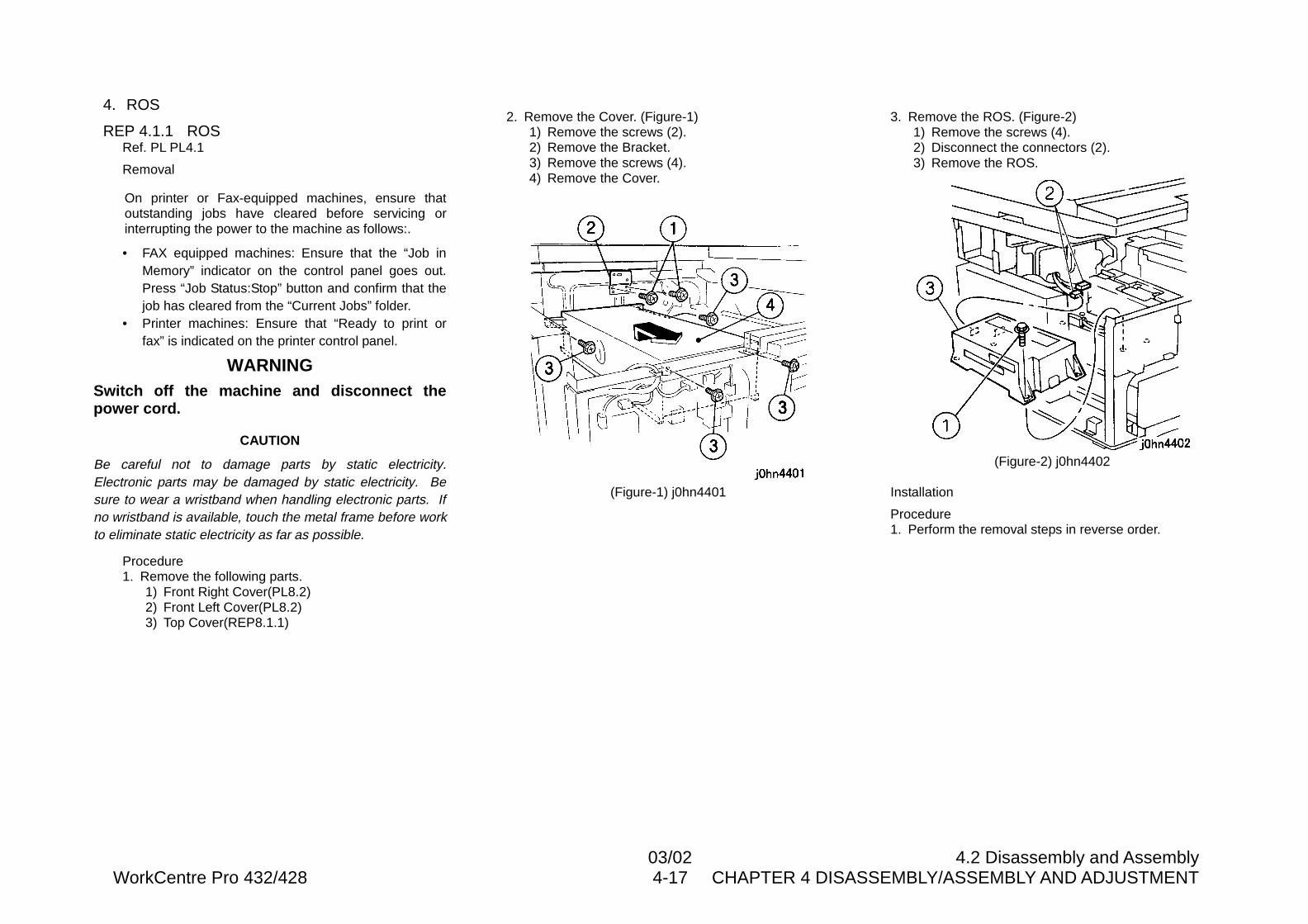
03/02 4.2 Disassembly and AssemblyWorkCentre Pro 432/428 4-17 CHAPTER 4 DISASSEMBLY/ASSEMBLY AND ADJUSTMENT
4. ROS
REP 4.1.1 ROSRef. PL PL4.1
Removal
On printer or Fax-equipped machines, ensure thatoutstanding jobs have cleared before servicing orinterrupting the power to the machine as follows:.
• FAX equipped machines: Ensure that the “Job inMemory” indicator on the control panel goes out.Press “Job Status:Stop” button and confirm that thejob has cleared from the “Current Jobs” folder.
• Printer machines: Ensure that “Ready to print orfax” is indicated on the printer control panel.
WARNINGSwitch off the machine and disconnect thepower cord.
CAUTION
Be careful not to damage parts by static electricity.Electronic parts may be damaged by static electricity. Besure to wear a wristband when handling electronic parts. Ifno wristband is available, touch the metal frame before workto eliminate static electricity as far as possible.
Procedure1. Remove the following parts.
1) Front Right Cover(PL8.2)2) Front Left Cover(PL8.2)3) Top Cover(REP8.1.1)
2. Remove the Cover. (Figure-1)1) Remove the screws (2).2) Remove the Bracket.3) Remove the screws (4).4) Remove the Cover.
(Figure-1) j0hn4401
3. Remove the ROS. (Figure-2)1) Remove the screws (4).2) Disconnect the connectors (2).3) Remove the ROS.
(Figure-2) j0hn4402
Installation
Procedure1. Perform the removal steps in reverse order.
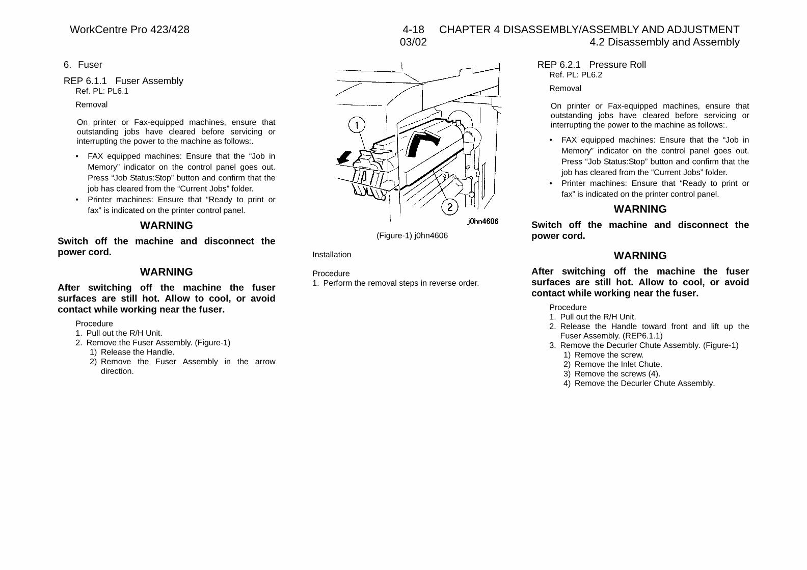
WorkCentre Pro 423/428 4-18 CHAPTER 4 DISASSEMBLY/ASSEMBLY AND ADJUSTMENT03/02 4.2 Disassembly and Assembly
6. Fuser
REP 6.1.1 Fuser AssemblyRef. PL: PL6.1
Removal
On printer or Fax-equipped machines, ensure thatoutstanding jobs have cleared before servicing orinterrupting the power to the machine as follows:.
• FAX equipped machines: Ensure that the “Job inMemory” indicator on the control panel goes out.Press “Job Status:Stop” button and confirm that thejob has cleared from the “Current Jobs” folder.
• Printer machines: Ensure that “Ready to print orfax” is indicated on the printer control panel.
WARNINGSwitch off the machine and disconnect thepower cord.
WARNINGAfter switching off the machine the fusersurfaces are still hot. Allow to cool, or avoidcontact while working near the fuser.
Procedure1. Pull out the R/H Unit.2. Remove the Fuser Assembly. (Figure-1)
1) Release the Handle.2) Remove the Fuser Assembly in the arrow
direction.
(Figure-1) j0hn4606
Installation
Procedure1. Perform the removal steps in reverse order.
REP 6.2.1 Pressure RollRef. PL: PL6.2
Removal
On printer or Fax-equipped machines, ensure thatoutstanding jobs have cleared before servicing orinterrupting the power to the machine as follows:.
• FAX equipped machines: Ensure that the “Job inMemory” indicator on the control panel goes out.Press “Job Status:Stop” button and confirm that thejob has cleared from the “Current Jobs” folder.
• Printer machines: Ensure that “Ready to print orfax” is indicated on the printer control panel.
WARNINGSwitch off the machine and disconnect thepower cord.
WARNINGAfter switching off the machine the fusersurfaces are still hot. Allow to cool, or avoidcontact while working near the fuser.
Procedure1. Pull out the R/H Unit.2. Release the Handle toward front and lift up the
Fuser Assembly. (REP6.1.1)3. Remove the Decurler Chute Assembly. (Figure-1)
1) Remove the screw.2) Remove the Inlet Chute.3) Remove the screws (4).4) Remove the Decurler Chute Assembly.
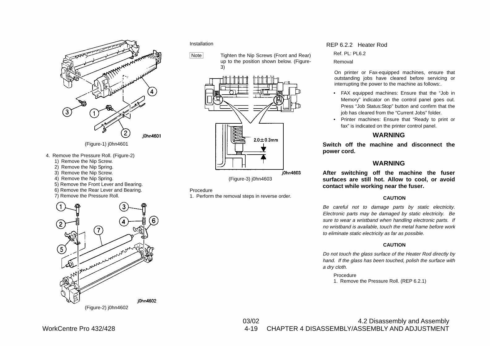
03/02 4.2 Disassembly and AssemblyWorkCentre Pro 432/428 4-19 CHAPTER 4 DISASSEMBLY/ASSEMBLY AND ADJUSTMENT
(Figure-1) j0hn4601
4. Remove the Pressure Roll. (Figure-2)1) Remove the Nip Screw.2) Remove the Nip Spring.3) Remove the Nip Screw.4) Remove the Nip Spring.5) Remove the Front Lever and Bearing.6) Remove the Rear Lever and Bearing.7) Remove the Pressure Roll.
(Figure-2) j0hn4602
Installation
Note Tighten the Nip Screws (Front and Rear)up to the position shown below. (Figure-3)
(Figure-3) j0hn4603
Procedure1. Perform the removal steps in reverse order.
REP 6.2.2 Heater RodRef. PL: PL6.2
Removal
On printer or Fax-equipped machines, ensure thatoutstanding jobs have cleared before servicing orinterrupting the power to the machine as follows:.
• FAX equipped machines: Ensure that the “Job inMemory” indicator on the control panel goes out.Press “Job Status:Stop” button and confirm that thejob has cleared from the “Current Jobs” folder.
• Printer machines: Ensure that “Ready to print orfax” is indicated on the printer control panel.
WARNINGSwitch off the machine and disconnect thepower cord.
WARNINGAfter switching off the machine the fusersurfaces are still hot. Allow to cool, or avoidcontact while working near the fuser.
CAUTION
Be careful not to damage parts by static electricity.Electronic parts may be damaged by static electricity. Besure to wear a wristband when handling electronic parts. Ifno wristband is available, touch the metal frame before workto eliminate static electricity as far as possible.
CAUTION
Do not touch the glass surface of the Heater Rod directly byhand. If the glass has been touched, polish the surface witha dry cloth.
Procedure1. Remove the Pressure Roll. (REP 6.2.1)
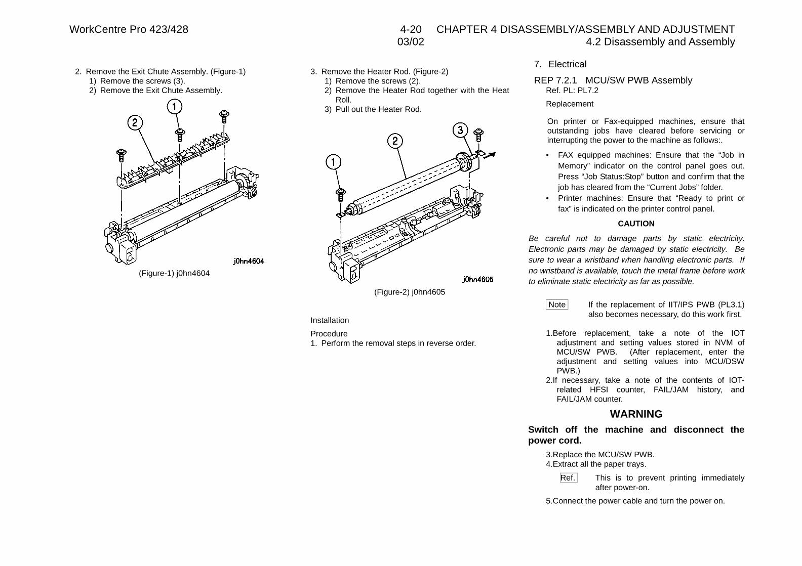
WorkCentre Pro 423/428 4-20 CHAPTER 4 DISASSEMBLY/ASSEMBLY AND ADJUSTMENT03/02 4.2 Disassembly and Assembly
2. Remove the Exit Chute Assembly. (Figure-1)1) Remove the screws (3).2) Remove the Exit Chute Assembly.
(Figure-1) j0hn4604
3. Remove the Heater Rod. (Figure-2)1) Remove the screws (2).2) Remove the Heater Rod together with the Heat
Roll.3) Pull out the Heater Rod.
(Figure-2) j0hn4605
Installation
Procedure1. Perform the removal steps in reverse order.
7. Electrical
REP 7.2.1 MCU/SW PWB AssemblyRef. PL: PL7.2
Replacement
On printer or Fax-equipped machines, ensure thatoutstanding jobs have cleared before servicing orinterrupting the power to the machine as follows:.
• FAX equipped machines: Ensure that the “Job inMemory” indicator on the control panel goes out.Press “Job Status:Stop” button and confirm that thejob has cleared from the “Current Jobs” folder.
• Printer machines: Ensure that “Ready to print orfax” is indicated on the printer control panel.
CAUTION
Be careful not to damage parts by static electricity.Electronic parts may be damaged by static electricity. Besure to wear a wristband when handling electronic parts. Ifno wristband is available, touch the metal frame before workto eliminate static electricity as far as possible.
Note If the replacement of IIT/IPS PWB (PL3.1)also becomes necessary, do this work first.
1.Before replacement, take a note of the IOTadjustment and setting values stored in NVM ofMCU/SW PWB. (After replacement, enter theadjustment and setting values into MCU/DSWPWB.)
2.If necessary, take a note of the contents of IOT-related HFSI counter, FAIL/JAM history, andFAIL/JAM counter.
WARNINGSwitch off the machine and disconnect thepower cord.
3.Replace the MCU/SW PWB.4.Extract all the paper trays.
Ref. This is to prevent printing immediatelyafter power-on.
5.Connect the power cable and turn the power on.
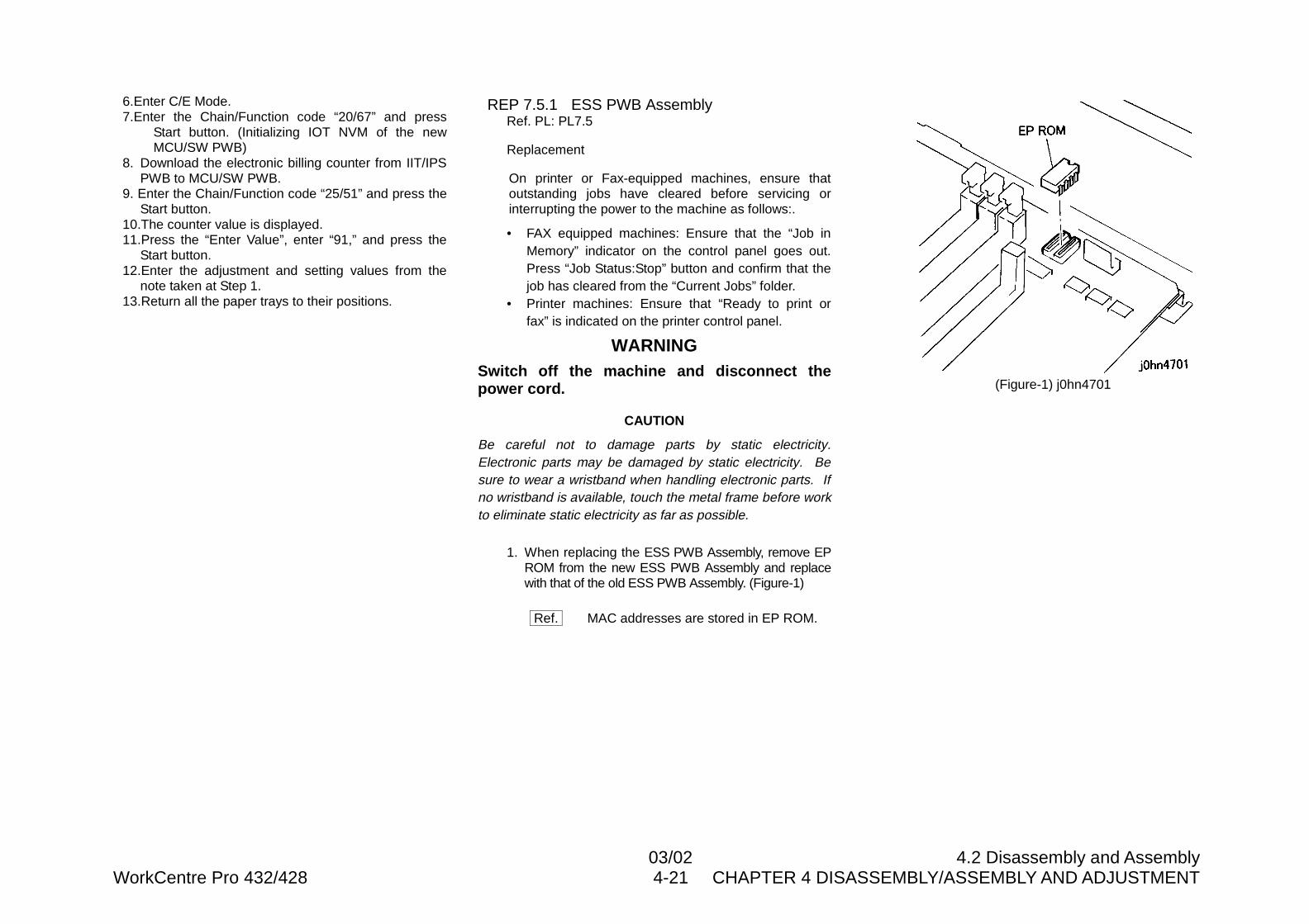
03/02 4.2 Disassembly and AssemblyWorkCentre Pro 432/428 4-21 CHAPTER 4 DISASSEMBLY/ASSEMBLY AND ADJUSTMENT
6.Enter C/E Mode.7.Enter the Chain/Function code “20/67” and press
Start button. (Initializing IOT NVM of the newMCU/SW PWB)
8. Download the electronic billing counter from IIT/IPSPWB to MCU/SW PWB.
9. Enter the Chain/Function code “25/51” and press theStart button.
10.The counter value is displayed.11.Press the “Enter Value”, enter “91,” and press the
Start button.12.Enter the adjustment and setting values from the
note taken at Step 1.13.Return all the paper trays to their positions.
REP 7.5.1 ESS PWB AssemblyRef. PL: PL7.5
Replacement
On printer or Fax-equipped machines, ensure thatoutstanding jobs have cleared before servicing orinterrupting the power to the machine as follows:.
• FAX equipped machines: Ensure that the “Job inMemory” indicator on the control panel goes out.Press “Job Status:Stop” button and confirm that thejob has cleared from the “Current Jobs” folder.
• Printer machines: Ensure that “Ready to print orfax” is indicated on the printer control panel.
WARNINGSwitch off the machine and disconnect thepower cord.
CAUTION
Be careful not to damage parts by static electricity.Electronic parts may be damaged by static electricity. Besure to wear a wristband when handling electronic parts. Ifno wristband is available, touch the metal frame before workto eliminate static electricity as far as possible.
1. When replacing the ESS PWB Assembly, remove EPROM from the new ESS PWB Assembly and replacewith that of the old ESS PWB Assembly. (Figure-1)
Ref. MAC addresses are stored in EP ROM.
(Figure-1) j0hn4701
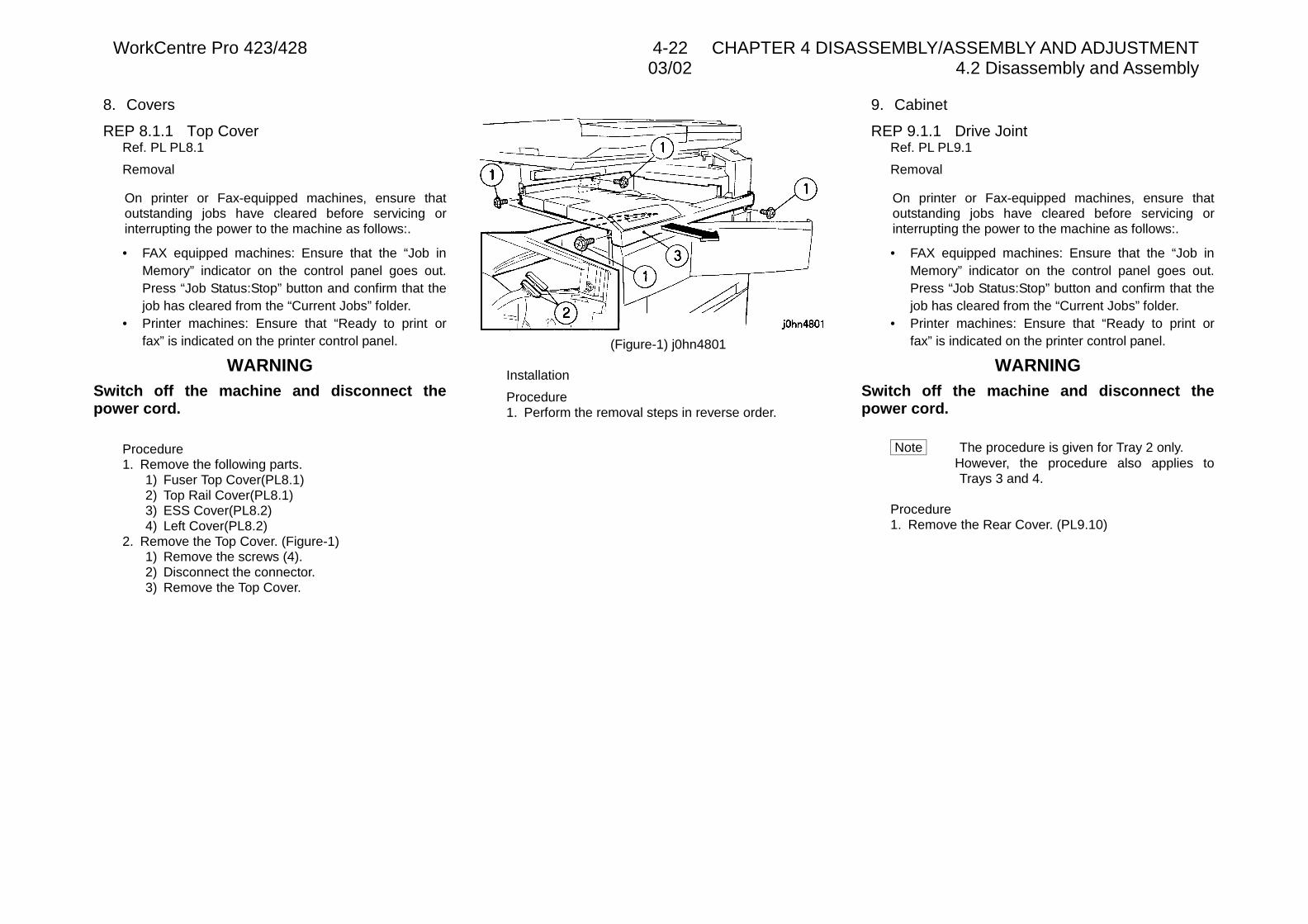
WorkCentre Pro 423/428 4-22 CHAPTER 4 DISASSEMBLY/ASSEMBLY AND ADJUSTMENT03/02 4.2 Disassembly and Assembly
8. Covers
REP 8.1.1 Top CoverRef. PL PL8.1
Removal
On printer or Fax-equipped machines, ensure thatoutstanding jobs have cleared before servicing orinterrupting the power to the machine as follows:.
• FAX equipped machines: Ensure that the “Job inMemory” indicator on the control panel goes out.Press “Job Status:Stop” button and confirm that thejob has cleared from the “Current Jobs” folder.
• Printer machines: Ensure that “Ready to print orfax” is indicated on the printer control panel.
WARNINGSwitch off the machine and disconnect thepower cord.
Procedure1. Remove the following parts.
1) Fuser Top Cover(PL8.1)2) Top Rail Cover(PL8.1)3) ESS Cover(PL8.2)4) Left Cover(PL8.2)
2. Remove the Top Cover. (Figure-1)1) Remove the screws (4).2) Disconnect the connector.3) Remove the Top Cover.
(Figure-1) j0hn4801
Installation
Procedure1. Perform the removal steps in reverse order.
9. Cabinet
REP 9.1.1 Drive JointRef. PL PL9.1
Removal
On printer or Fax-equipped machines, ensure thatoutstanding jobs have cleared before servicing orinterrupting the power to the machine as follows:.
• FAX equipped machines: Ensure that the “Job inMemory” indicator on the control panel goes out.Press “Job Status:Stop” button and confirm that thejob has cleared from the “Current Jobs” folder.
• Printer machines: Ensure that “Ready to print orfax” is indicated on the printer control panel.
WARNINGSwitch off the machine and disconnect thepower cord.
Note The procedure is given for Tray 2 only.However, the procedure also applies toTrays 3 and 4.
Procedure1. Remove the Rear Cover. (PL9.10)
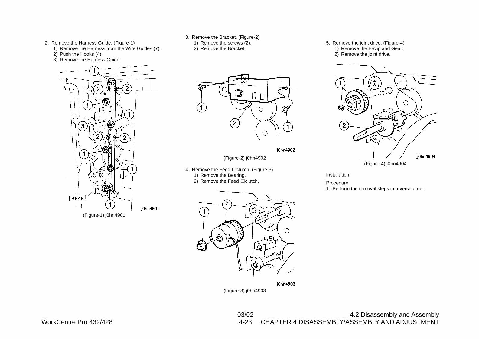
03/02 4.2 Disassembly and AssemblyWorkCentre Pro 432/428 4-23 CHAPTER 4 DISASSEMBLY/ASSEMBLY AND ADJUSTMENT
2. Remove the Harness Guide. (Figure-1)1) Remove the Harness from the Wire Guides (7).2) Push the Hooks (4).3) Remove the Harness Guide.
(Figure-1) j0hn4901
3. Remove the Bracket. (Figure-2)1) Remove the screws (2).2) Remove the Bracket.
(Figure-2) j0hn4902
4. Remove the Feed �clutch. (Figure-3)1) Remove the Bearing.2) Remove the Feed �clutch.
(Figure-3) j0hn4903
5. Remove the joint drive. (Figure-4)1) Remove the E-clip and Gear.2) Remove the joint drive.
(Figure-4) j0hn4904
Installation
Procedure1. Perform the removal steps in reverse order.
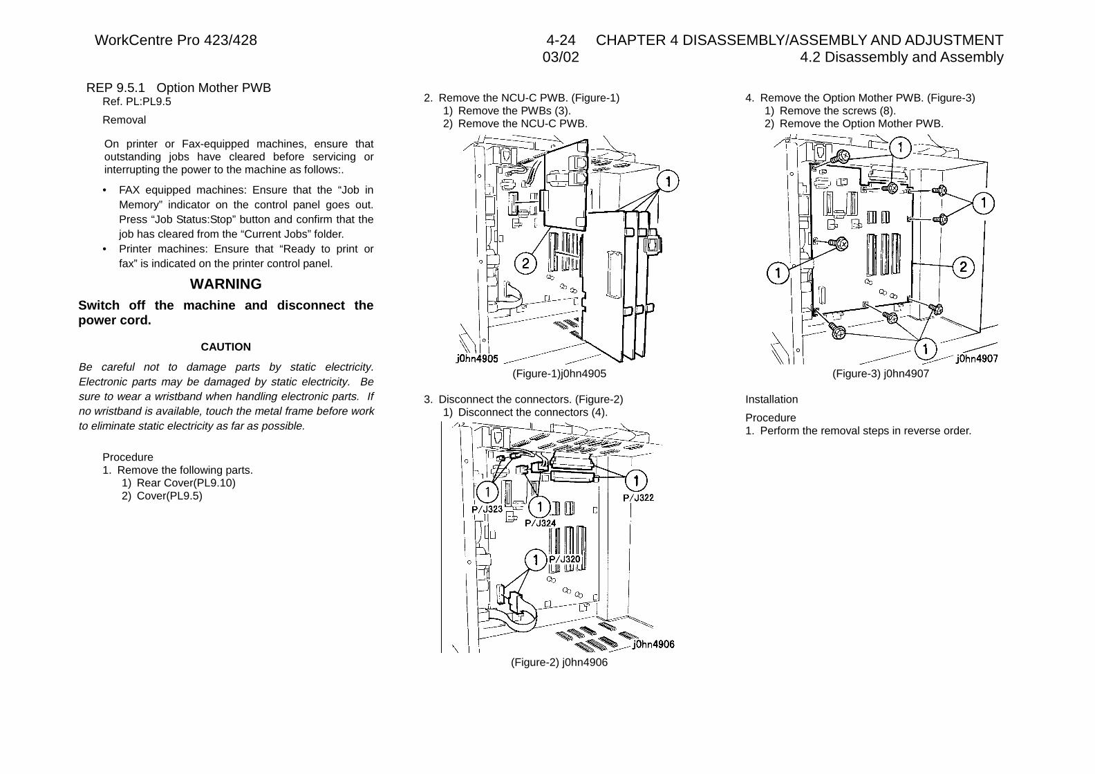
WorkCentre Pro 423/428 4-24 CHAPTER 4 DISASSEMBLY/ASSEMBLY AND ADJUSTMENT03/02 4.2 Disassembly and Assembly
REP 9.5.1 Option Mother PWBRef. PL:PL9.5
Removal
On printer or Fax-equipped machines, ensure thatoutstanding jobs have cleared before servicing orinterrupting the power to the machine as follows:.
• FAX equipped machines: Ensure that the “Job inMemory” indicator on the control panel goes out.Press “Job Status:Stop” button and confirm that thejob has cleared from the “Current Jobs” folder.
• Printer machines: Ensure that “Ready to print orfax” is indicated on the printer control panel.
WARNINGSwitch off the machine and disconnect thepower cord.
CAUTION
Be careful not to damage parts by static electricity.Electronic parts may be damaged by static electricity. Besure to wear a wristband when handling electronic parts. Ifno wristband is available, touch the metal frame before workto eliminate static electricity as far as possible.
Procedure1. Remove the following parts.
1) Rear Cover(PL9.10)2) Cover(PL9.5)
2. Remove the NCU-C PWB. (Figure-1)1) Remove the PWBs (3).2) Remove the NCU-C PWB.
(Figure-1)j0hn4905
3. Disconnect the connectors. (Figure-2)1) Disconnect the connectors (4).
(Figure-2) j0hn4906
4. Remove the Option Mother PWB. (Figure-3)1) Remove the screws (8).2) Remove the Option Mother PWB.
(Figure-3) j0hn4907
Installation
Procedure1. Perform the removal steps in reverse order.
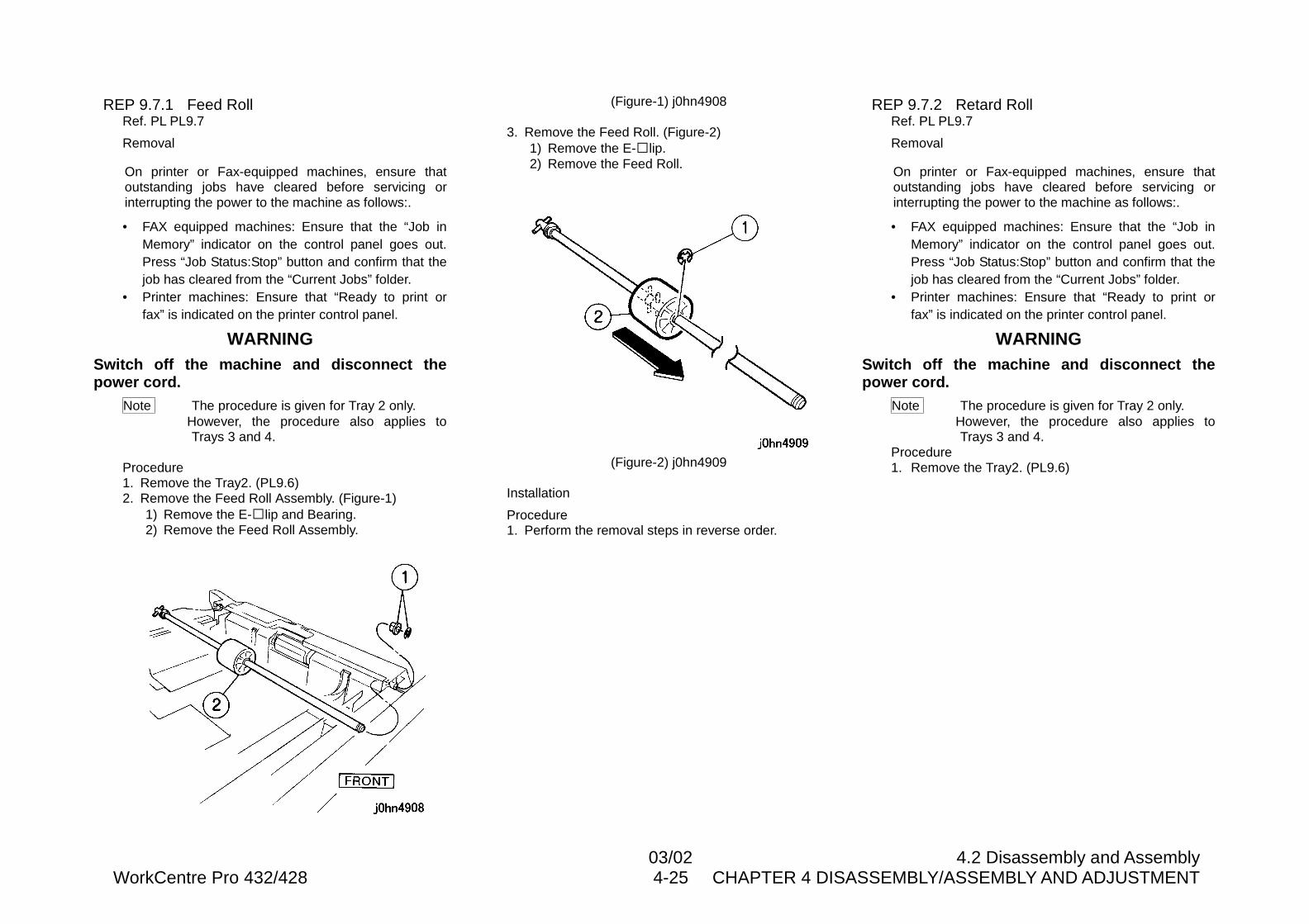
03/02 4.2 Disassembly and AssemblyWorkCentre Pro 432/428 4-25 CHAPTER 4 DISASSEMBLY/ASSEMBLY AND ADJUSTMENT
REP 9.7.1 Feed RollRef. PL PL9.7
Removal
On printer or Fax-equipped machines, ensure thatoutstanding jobs have cleared before servicing orinterrupting the power to the machine as follows:.
• FAX equipped machines: Ensure that the “Job inMemory” indicator on the control panel goes out.Press “Job Status:Stop” button and confirm that thejob has cleared from the “Current Jobs” folder.
• Printer machines: Ensure that “Ready to print orfax” is indicated on the printer control panel.
WARNINGSwitch off the machine and disconnect thepower cord.
Note The procedure is given for Tray 2 only.However, the procedure also applies toTrays 3 and 4.
Procedure1. Remove the Tray2. (PL9.6)2. Remove the Feed Roll Assembly. (Figure-1)
1) Remove the E-�lip and Bearing.2) Remove the Feed Roll Assembly.
(Figure-1) j0hn4908
3. Remove the Feed Roll. (Figure-2)1) Remove the E-�lip.2) Remove the Feed Roll.
(Figure-2) j0hn4909
Installation
Procedure1. Perform the removal steps in reverse order.
REP 9.7.2 Retard RollRef. PL PL9.7
Removal
On printer or Fax-equipped machines, ensure thatoutstanding jobs have cleared before servicing orinterrupting the power to the machine as follows:.
• FAX equipped machines: Ensure that the “Job inMemory” indicator on the control panel goes out.Press “Job Status:Stop” button and confirm that thejob has cleared from the “Current Jobs” folder.
• Printer machines: Ensure that “Ready to print orfax” is indicated on the printer control panel.
WARNINGSwitch off the machine and disconnect thepower cord.
Note The procedure is given for Tray 2 only.However, the procedure also applies toTrays 3 and 4.
Procedure1. Remove the Tray2. (PL9.6)
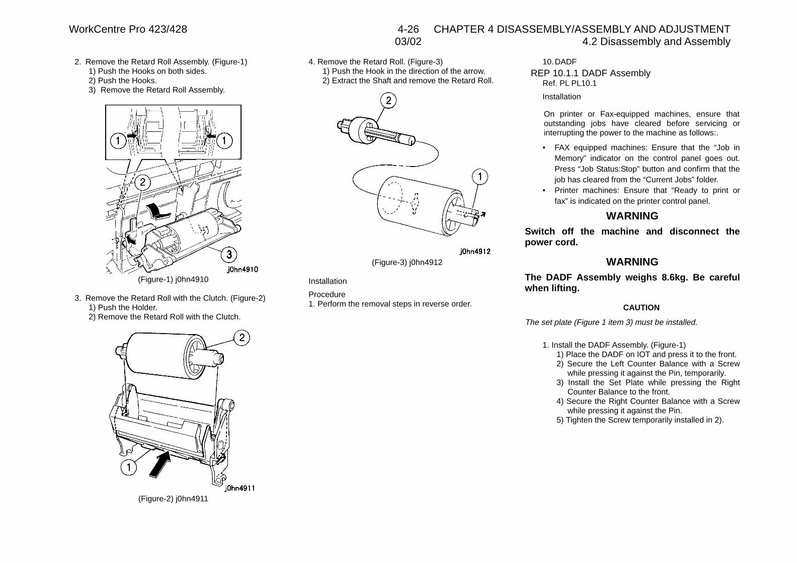
WorkCentre Pro 423/428 4-26 CHAPTER 4 DISASSEMBLY/ASSEMBLY AND ADJUSTMENT03/02 4.2 Disassembly and Assembly
2. Remove the Retard Roll Assembly. (Figure-1)1) Push the Hooks on both sides.2) Push the Hooks.3) Remove the Retard Roll Assembly.
(Figure-1) j0hn4910
3. Remove the Retard Roll with the Clutch. (Figure-2)1) Push the Holder.2) Remove the Retard Roll with the Clutch.
(Figure-2) j0hn4911
4. Remove the Retard Roll. (Figure-3)1) Push the Hook in the direction of the arrow.2) Extract the Shaft and remove the Retard Roll.
(Figure-3) j0hn4912
Installation
Procedure1. Perform the removal steps in reverse order.
10.DADF
REP 10.1.1 DADF AssemblyRef. PL PL10.1
Installation
On printer or Fax-equipped machines, ensure thatoutstanding jobs have cleared before servicing orinterrupting the power to the machine as follows:.
• FAX equipped machines: Ensure that the “Job inMemory” indicator on the control panel goes out.Press “Job Status:Stop” button and confirm that thejob has cleared from the “Current Jobs” folder.
• Printer machines: Ensure that “Ready to print orfax” is indicated on the printer control panel.
WARNINGSwitch off the machine and disconnect thepower cord.
WARNINGThe DADF Assembly weighs 8.6kg. Be carefulwhen lifting.
CAUTION
The set plate (Figure 1 item 3) must be installed.
1. Install the DADF Assembly. (Figure-1)1) Place the DADF on IOT and press it to the front.2) Secure the Left Counter Balance with a Screw
while pressing it against the Pin, temporarily.3) Install the Set Plate while pressing the Right
Counter Balance to the front.4) Secure the Right Counter Balance with a Screw
while pressing it against the Pin.5) Tighten the Screw temporarily installed in 2).
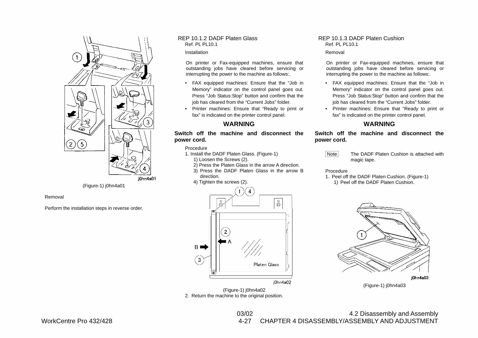
03/02 4.2 Disassembly and AssemblyWorkCentre Pro 432/428 4-27 CHAPTER 4 DISASSEMBLY/ASSEMBLY AND ADJUSTMENT
(Figure-1) j0hn4a01
Removal
Perform the installation steps in reverse order.
REP 10.1.2 DADF Platen GlassRef. PL PL10.1
Installation
On printer or Fax-equipped machines, ensure thatoutstanding jobs have cleared before servicing orinterrupting the power to the machine as follows:.
• FAX equipped machines: Ensure that the “Job inMemory” indicator on the control panel goes out.Press “Job Status:Stop” button and confirm that thejob has cleared from the “Current Jobs” folder.
• Printer machines: Ensure that “Ready to print orfax” is indicated on the printer control panel.
WARNINGSwitch off the machine and disconnect thepower cord.
Procedure1. Install the DADF Platen Glass. (Figure-1)
1) Loosen the Screws (2).2) Press the Platen Glass in the arrow A direction.3) Press the DADF Platen Glass in the arrow B
direction.4) Tighten the screws (2).
(Figure-1) j0hn4a022. Return the machine to the original position.
REP 10.1.3 DADF Platen CushionRef. PL PL10.1
Removal
On printer or Fax-equipped machines, ensure thatoutstanding jobs have cleared before servicing orinterrupting the power to the machine as follows:.
• FAX equipped machines: Ensure that the “Job inMemory” indicator on the control panel goes out.Press “Job Status:Stop” button and confirm that thejob has cleared from the “Current Jobs” folder.
• Printer machines: Ensure that “Ready to print orfax” is indicated on the printer control panel.
WARNINGSwitch off the machine and disconnect thepower cord.
Note The DADF Platen Cushion is attached withmagic tape.
Procedure1. Peel off the DADF Platen Cushion. (Figure-1)
1) Peel off the DADF Platen Cushion.
(Figure-1) j0hn4a03
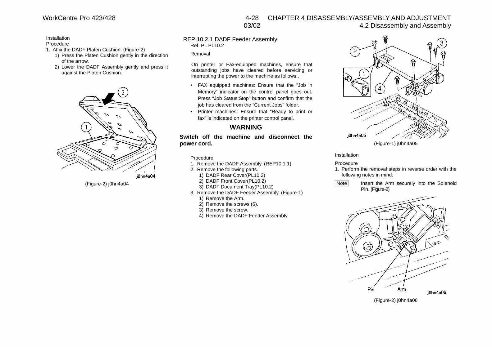
WorkCentre Pro 423/428 4-28 CHAPTER 4 DISASSEMBLY/ASSEMBLY AND ADJUSTMENT03/02 4.2 Disassembly and Assembly
InstallationProcedure1. Affix the DADF Platen Cushion. (Figure-2)
1) Press the Platen Cushion gently in the directionof the arrow.
2) Lower the DADF Assembly gently and press itagainst the Platen Cushion.
(Figure-2) j0hn4a04
REP.10.2.1 DADF Feeder AssemblyRef. PL PL10.2
Removal
On printer or Fax-equipped machines, ensure thatoutstanding jobs have cleared before servicing orinterrupting the power to the machine as follows:.
• FAX equipped machines: Ensure that the “Job inMemory” indicator on the control panel goes out.Press “Job Status:Stop” button and confirm that thejob has cleared from the “Current Jobs” folder.
• Printer machines: Ensure that “Ready to print orfax” is indicated on the printer control panel.
WARNINGSwitch off the machine and disconnect thepower cord.
Procedure1. Remove the DADF Assembly. (REP10.1.1)2. Remove the following parts.
1) DADF Rear Cover(PL10.2)2) DADF Front Cover(PL10.2)3) DADF Document Tray(PL10.2)
3. Remove the DADF Feeder Assembly. (Figure-1)1) Remove the Arm.2) Remove the screws (6).3) Remove the screw.4) Remove the DADF Feeder Assembly.
(Figure-1) j0hn4a05
Installation
Procedure1. Perform the removal steps in reverse order with the
following notes in mind.
Note Insert the Arm securely into the SolenoidPin. (Figure-2)
(Figure-2) j0hn4a06
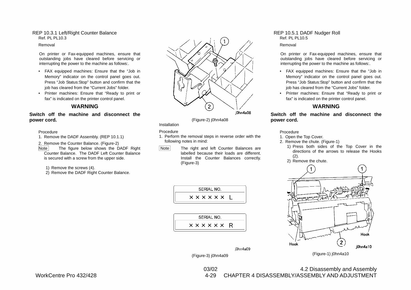
03/02 4.2 Disassembly and AssemblyWorkCentre Pro 432/428 4-29 CHAPTER 4 DISASSEMBLY/ASSEMBLY AND ADJUSTMENT
REP 10.3.1 Left/Right Counter BalanceRef. PL PL10.3
Removal
On printer or Fax-equipped machines, ensure thatoutstanding jobs have cleared before servicing orinterrupting the power to the machine as follows:.
• FAX equipped machines: Ensure that the “Job inMemory” indicator on the control panel goes out.Press “Job Status:Stop” button and confirm that thejob has cleared from the “Current Jobs” folder.
• Printer machines: Ensure that “Ready to print orfax” is indicated on the printer control panel.
WARNINGSwitch off the machine and disconnect thepower cord.
Procedure1. Remove the DADF Assembly. (REP 10.1.1)
2. Remove the Counter Balance. (Figure-2)Note The figure below shows the DADF Right
Counter Balance. The DADF Left Counter Balanceis secured with a screw from the upper side.
1) Remove the screws (4).2) Remove the DADF Right Counter Balance.
(Figure-2) j0hn4a08Installation
Procedure1. Perform the removal steps in reverse order with the
following notes in mind:
Note The right and left Counter Balances arelabelled because their loads are different.Install the Counter Balances correctly.(Figure-3)
(Figure-3) j0hn4a09
REP 10.5.1 DADF Nudger RollRef. PL PL10.5
Removal
On printer or Fax-equipped machines, ensure thatoutstanding jobs have cleared before servicing orinterrupting the power to the machine as follows:.
• FAX equipped machines: Ensure that the “Job inMemory” indicator on the control panel goes out.Press “Job Status:Stop” button and confirm that thejob has cleared from the “Current Jobs” folder.
• Printer machines: Ensure that “Ready to print orfax” is indicated on the printer control panel.
WARNINGSwitch off the machine and disconnect thepower cord.
Procedure1. Open the Top Cover.2. Remove the chute. (Figure-1)
1) Press both sides of the Top Cover in thedirections of the arrows to release the Hooks(2).
2) Remove the chute.
(Figure-1) j0hn4a10
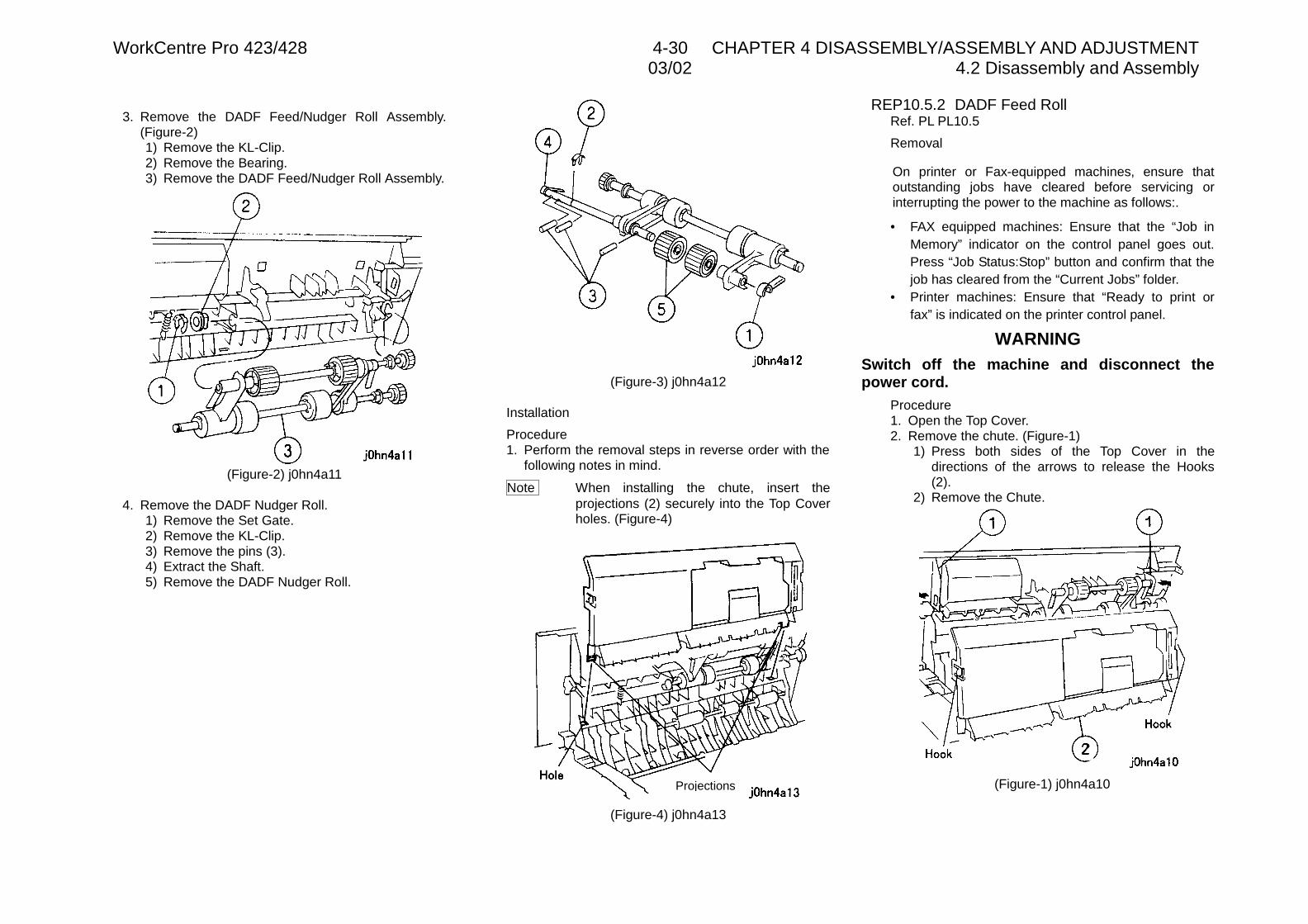
WorkCentre Pro 423/428 4-30 CHAPTER 4 DISASSEMBLY/ASSEMBLY AND ADJUSTMENT03/02 4.2 Disassembly and Assembly
3. Remove the DADF Feed/Nudger Roll Assembly.(Figure-2)1) Remove the KL-Clip.2) Remove the Bearing.3) Remove the DADF Feed/Nudger Roll Assembly.
(Figure-2) j0hn4a11
4. Remove the DADF Nudger Roll.1) Remove the Set Gate.2) Remove the KL-Clip.3) Remove the pins (3).4) Extract the Shaft.5) Remove the DADF Nudger Roll.
(Figure-3) j0hn4a12
Installation
Procedure1. Perform the removal steps in reverse order with the
following notes in mind.
Note When installing the chute, insert theprojections (2) securely into the Top Coverholes. (Figure-4)
(Figure-4) j0hn4a13
REP10.5.2 DADF Feed RollRef. PL PL10.5
Removal
On printer or Fax-equipped machines, ensure thatoutstanding jobs have cleared before servicing orinterrupting the power to the machine as follows:.
• FAX equipped machines: Ensure that the “Job inMemory” indicator on the control panel goes out.Press “Job Status:Stop” button and confirm that thejob has cleared from the “Current Jobs” folder.
• Printer machines: Ensure that “Ready to print orfax” is indicated on the printer control panel.
WARNINGSwitch off the machine and disconnect thepower cord.
Procedure1. Open the Top Cover.2. Remove the chute. (Figure-1)
1) Press both sides of the Top Cover in thedirections of the arrows to release the Hooks(2).
2) Remove the Chute.
(Figure-1) j0hn4a10Projections
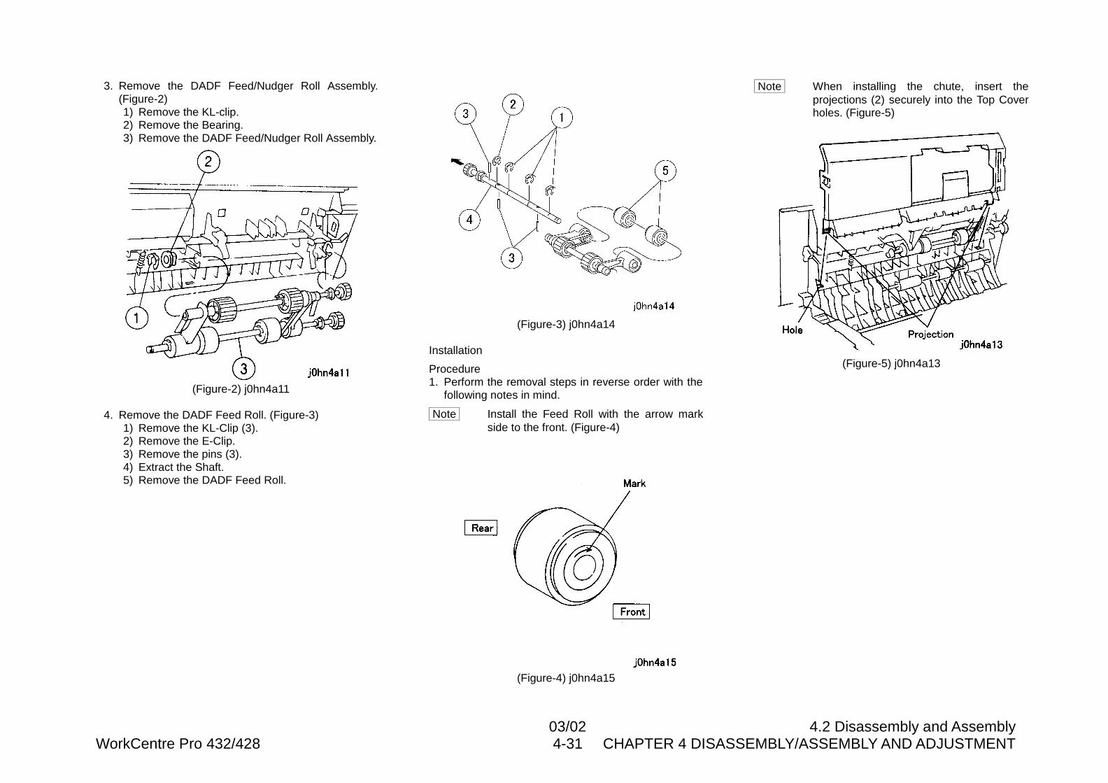
03/02 4.2 Disassembly and AssemblyWorkCentre Pro 432/428 4-31 CHAPTER 4 DISASSEMBLY/ASSEMBLY AND ADJUSTMENT
3. Remove the DADF Feed/Nudger Roll Assembly.(Figure-2)1) Remove the KL-clip.2) Remove the Bearing.3) Remove the DADF Feed/Nudger Roll Assembly.
(Figure-2) j0hn4a11
4. Remove the DADF Feed Roll. (Figure-3)1) Remove the KL-Clip (3).2) Remove the E-Clip.3) Remove the pins (3).4) Extract the Shaft.5) Remove the DADF Feed Roll.
(Figure-3) j0hn4a14
Installation
Procedure1. Perform the removal steps in reverse order with the
following notes in mind.
Note Install the Feed Roll with the arrow markside to the front. (Figure-4)
(Figure-4) j0hn4a15
Note When installing the chute, insert theprojections (2) securely into the Top Coverholes. (Figure-5)
(Figure-5) j0hn4a13
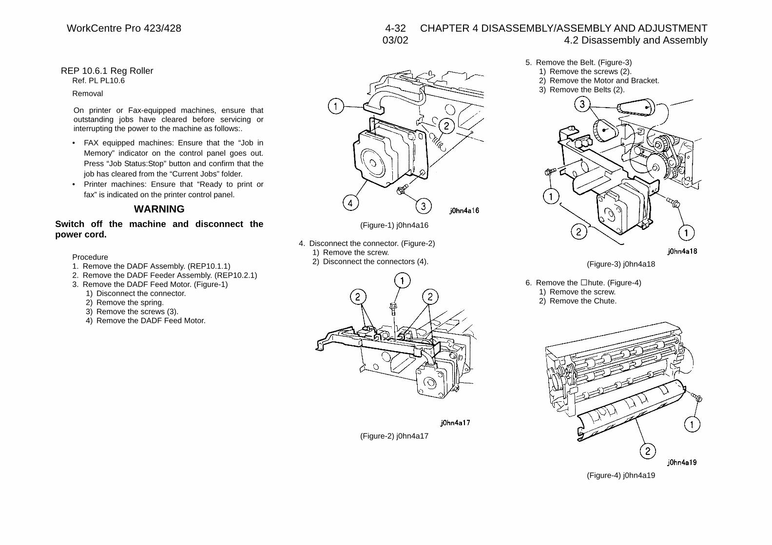
WorkCentre Pro 423/428 4-32 CHAPTER 4 DISASSEMBLY/ASSEMBLY AND ADJUSTMENT03/02 4.2 Disassembly and Assembly
REP 10.6.1 Reg RollerRef. PL PL10.6
Removal
On printer or Fax-equipped machines, ensure thatoutstanding jobs have cleared before servicing orinterrupting the power to the machine as follows:.
• FAX equipped machines: Ensure that the “Job inMemory” indicator on the control panel goes out.Press “Job Status:Stop” button and confirm that thejob has cleared from the “Current Jobs” folder.
• Printer machines: Ensure that “Ready to print orfax” is indicated on the printer control panel.
WARNINGSwitch off the machine and disconnect thepower cord.
Procedure1. Remove the DADF Assembly. (REP10.1.1)2. Remove the DADF Feeder Assembly. (REP10.2.1)3. Remove the DADF Feed Motor. (Figure-1)
1) Disconnect the connector.2) Remove the spring.3) Remove the screws (3).4) Remove the DADF Feed Motor.
(Figure-1) j0hn4a16
4. Disconnect the connector. (Figure-2)1) Remove the screw.2) Disconnect the connectors (4).
(Figure-2) j0hn4a17
5. Remove the Belt. (Figure-3)1) Remove the screws (2).2) Remove the Motor and Bracket.3) Remove the Belts (2).
(Figure-3) j0hn4a18
6. Remove the �hute. (Figure-4)1) Remove the screw.2) Remove the Chute.
(Figure-4) j0hn4a19
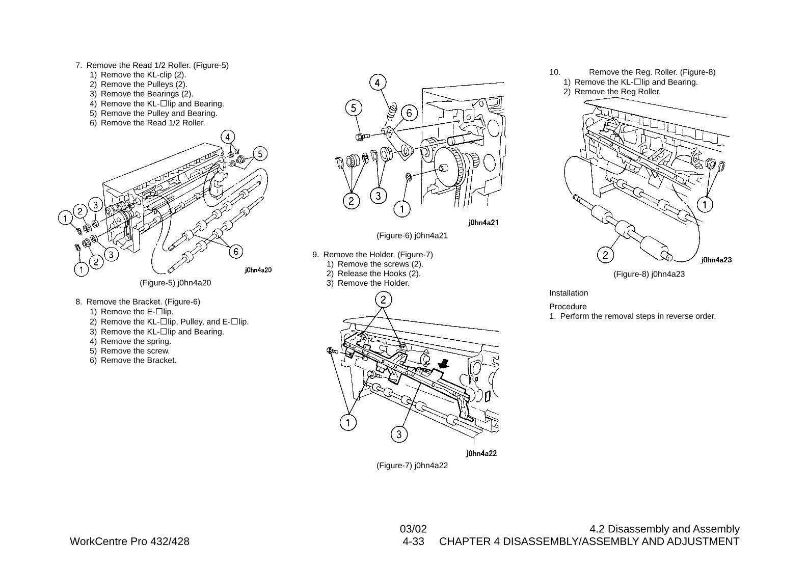
03/02 4.2 Disassembly and AssemblyWorkCentre Pro 432/428 4-33 CHAPTER 4 DISASSEMBLY/ASSEMBLY AND ADJUSTMENT
7. Remove the Read 1/2 Roller. (Figure-5)1) Remove the KL-clip (2).2) Remove the Pulleys (2).3) Remove the Bearings (2).4) Remove the KL-�lip and Bearing.5) Remove the Pulley and Bearing.6) Remove the Read 1/2 Roller.
(Figure-5) j0hn4a20
8. Remove the Bracket. (Figure-6)1) Remove the E-�lip.2) Remove the KL-�lip, Pulley, and E-�lip.3) Remove the KL-�lip and Bearing.4) Remove the spring.5) Remove the screw.6) Remove the Bracket.
(Figure-6) j0hn4a21
9. Remove the Holder. (Figure-7)1) Remove the screws (2).2) Release the Hooks (2).3) Remove the Holder.
(Figure-7) j0hn4a22
10. Remove the Reg. Roller. (Figure-8)1) Remove the KL-�lip and Bearing.2) Remove the Reg Roller.
(Figure-8) j0hn4a23
Installation
Procedure1. Perform the removal steps in reverse order.
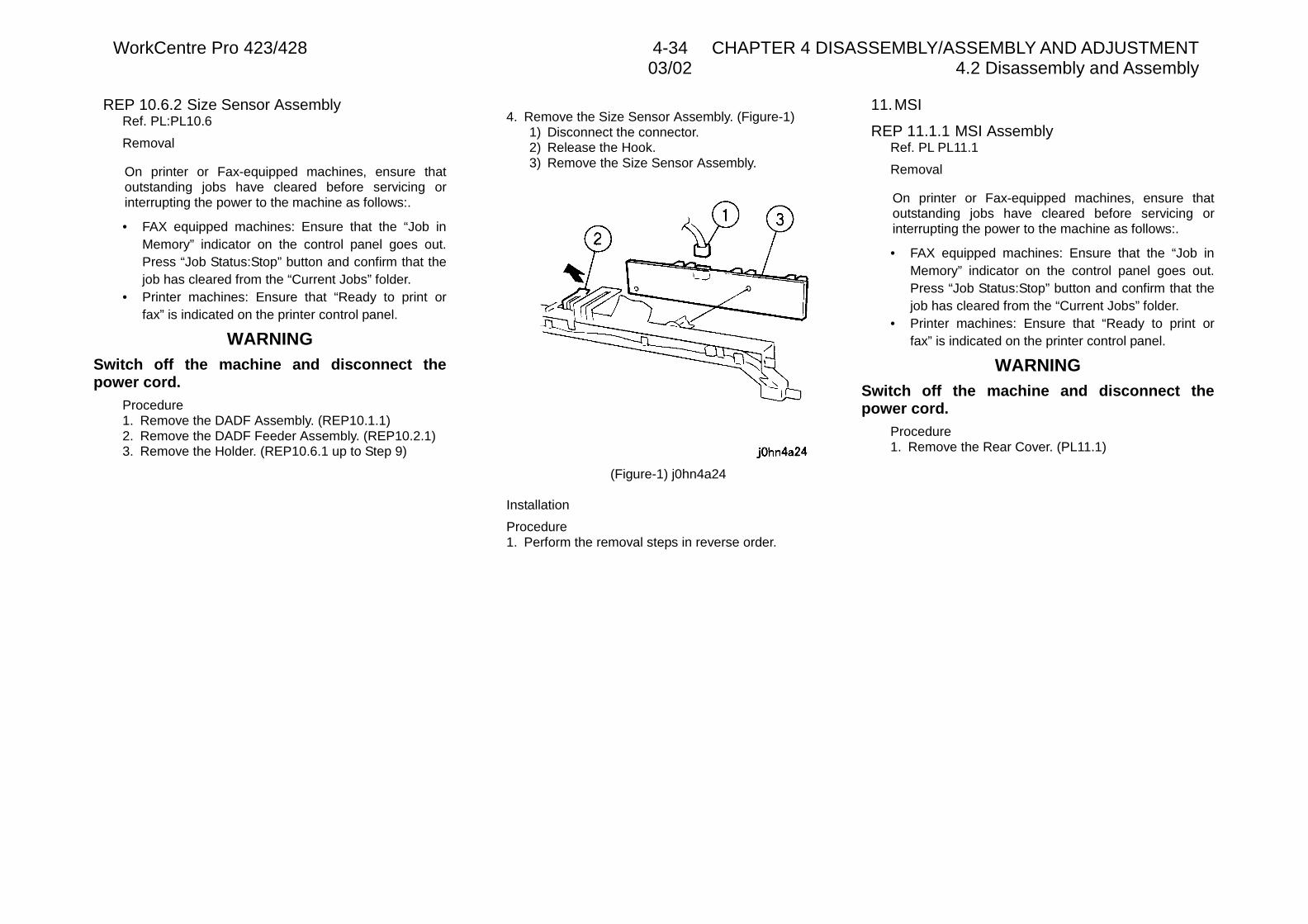
WorkCentre Pro 423/428 4-34 CHAPTER 4 DISASSEMBLY/ASSEMBLY AND ADJUSTMENT03/02 4.2 Disassembly and Assembly
REP 10.6.2 Size Sensor AssemblyRef. PL:PL10.6
Removal
On printer or Fax-equipped machines, ensure thatoutstanding jobs have cleared before servicing orinterrupting the power to the machine as follows:.
• FAX equipped machines: Ensure that the “Job inMemory” indicator on the control panel goes out.Press “Job Status:Stop” button and confirm that thejob has cleared from the “Current Jobs” folder.
• Printer machines: Ensure that “Ready to print orfax” is indicated on the printer control panel.
WARNINGSwitch off the machine and disconnect thepower cord.
Procedure1. Remove the DADF Assembly. (REP10.1.1)2. Remove the DADF Feeder Assembly. (REP10.2.1)3. Remove the Holder. (REP10.6.1 up to Step 9)
4. Remove the Size Sensor Assembly. (Figure-1)1) Disconnect the connector.2) Release the Hook.3) Remove the Size Sensor Assembly.
(Figure-1) j0hn4a24
Installation
Procedure1. Perform the removal steps in reverse order.
11.MSI
REP 11.1.1 MSI AssemblyRef. PL PL11.1
Removal
On printer or Fax-equipped machines, ensure thatoutstanding jobs have cleared before servicing orinterrupting the power to the machine as follows:.
• FAX equipped machines: Ensure that the “Job inMemory” indicator on the control panel goes out.Press “Job Status:Stop” button and confirm that thejob has cleared from the “Current Jobs” folder.
• Printer machines: Ensure that “Ready to print orfax” is indicated on the printer control panel.
WARNINGSwitch off the machine and disconnect thepower cord.
Procedure1. Remove the Rear Cover. (PL11.1)
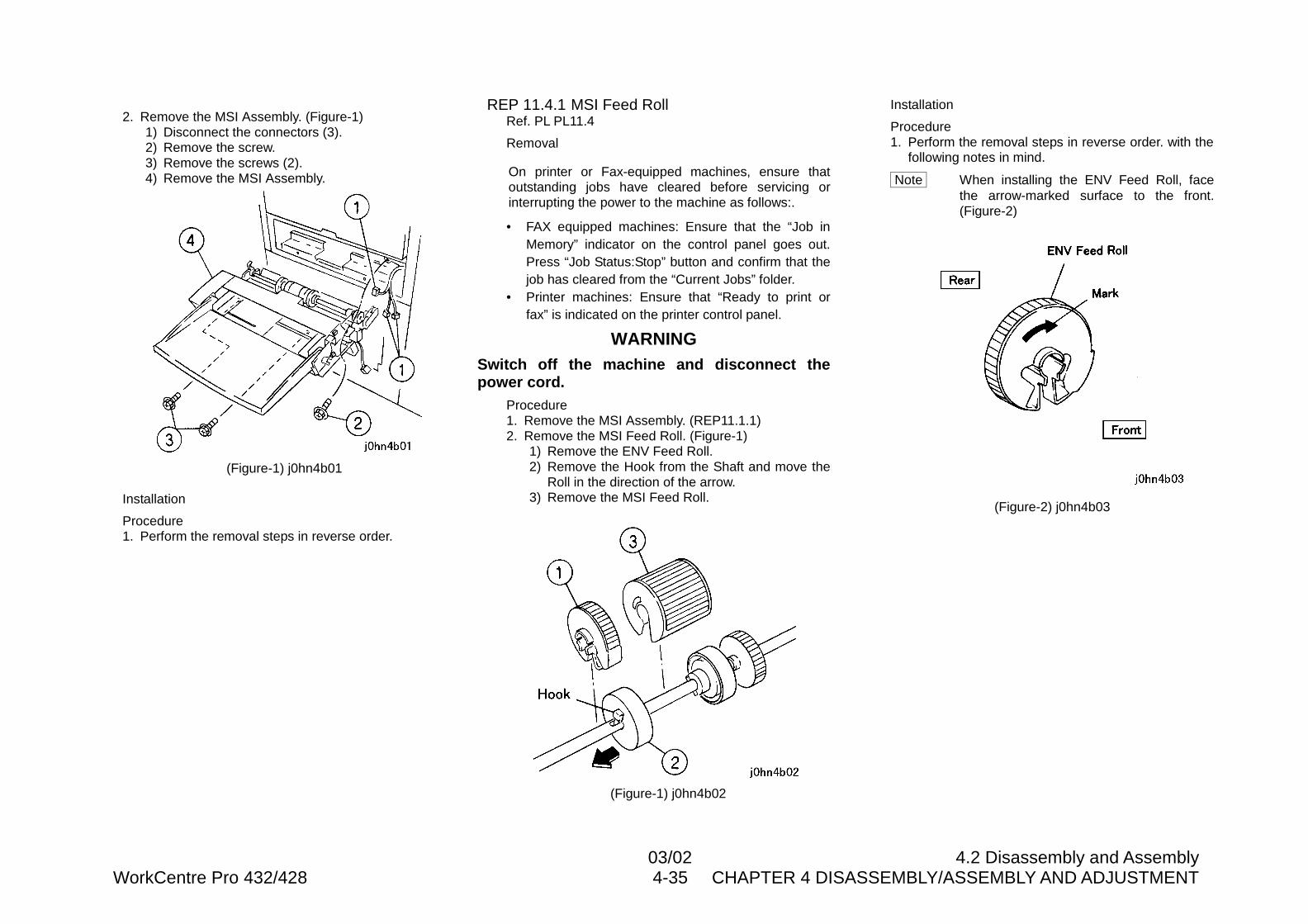
03/02 4.2 Disassembly and AssemblyWorkCentre Pro 432/428 4-35 CHAPTER 4 DISASSEMBLY/ASSEMBLY AND ADJUSTMENT
2. Remove the MSI Assembly. (Figure-1)1) Disconnect the connectors (3).2) Remove the screw.3) Remove the screws (2).4) Remove the MSI Assembly.
(Figure-1) j0hn4b01
Installation
Procedure1. Perform the removal steps in reverse order.
REP 11.4.1 MSI Feed RollRef. PL PL11.4
Removal
On printer or Fax-equipped machines, ensure thatoutstanding jobs have cleared before servicing orinterrupting the power to the machine as follows:.
• FAX equipped machines: Ensure that the “Job inMemory” indicator on the control panel goes out.Press “Job Status:Stop” button and confirm that thejob has cleared from the “Current Jobs” folder.
• Printer machines: Ensure that “Ready to print orfax” is indicated on the printer control panel.
WARNINGSwitch off the machine and disconnect thepower cord.
Procedure1. Remove the MSI Assembly. (REP11.1.1)2. Remove the MSI Feed Roll. (Figure-1)
1) Remove the ENV Feed Roll.2) Remove the Hook from the Shaft and move the
Roll in the direction of the arrow.3) Remove the MSI Feed Roll.
(Figure-1) j0hn4b02
Installation
Procedure1. Perform the removal steps in reverse order. with the
following notes in mind.
Note When installing the ENV Feed Roll, facethe arrow-marked surface to the front.(Figure-2)
(Figure-2) j0hn4b03
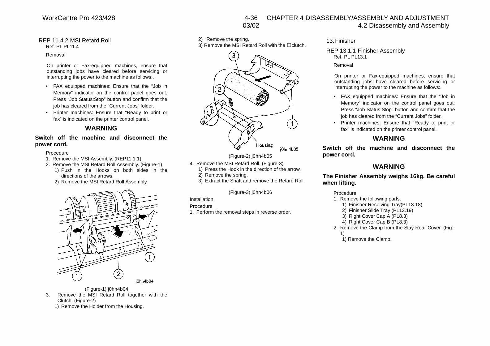
WorkCentre Pro 423/428 4-36 CHAPTER 4 DISASSEMBLY/ASSEMBLY AND ADJUSTMENT03/02 4.2 Disassembly and Assembly
REP 11.4.2 MSI Retard RollRef. PL PL11.4
Removal
On printer or Fax-equipped machines, ensure thatoutstanding jobs have cleared before servicing orinterrupting the power to the machine as follows:.
• FAX equipped machines: Ensure that the “Job inMemory” indicator on the control panel goes out.Press “Job Status:Stop” button and confirm that thejob has cleared from the “Current Jobs” folder.
• Printer machines: Ensure that “Ready to print orfax” is indicated on the printer control panel.
WARNINGSwitch off the machine and disconnect thepower cord.
Procedure1. Remove the MSI Assembly. (REP11.1.1)2. Remove the MSI Retard Roll Assembly. (Figure-1)
1) Push in the Hooks on both sides in thedirections of the arrows.
2) Remove the MSI Retard Roll Assembly.
(Figure-1) j0hn4b043. Remove the MSI Retard Roll together with the
Clutch. (Figure-2)1) Remove the Holder from the Housing.
2) Remove the spring.3) Remove the MSI Retard Roll with the �clutch.
(Figure-2) j0hn4b05
4. Remove the MSI Retard Roll. (Figure-3)1) Press the Hook in the direction of the arrow.2) Remove the spring.3) Extract the Shaft and remove the Retard Roll.
(Figure-3) j0hn4b06InstallationProcedure1. Perform the removal steps in reverse order.
13.Finisher
REP 13.1.1 Finisher AssemblyRef. PL PL13.1
Removal
On printer or Fax-equipped machines, ensure thatoutstanding jobs have cleared before servicing orinterrupting the power to the machine as follows:.
• FAX equipped machines: Ensure that the “Job inMemory” indicator on the control panel goes out.Press “Job Status:Stop” button and confirm that thejob has cleared from the “Current Jobs” folder.
• Printer machines: Ensure that “Ready to print orfax” is indicated on the printer control panel.
WARNINGSwitch off the machine and disconnect thepower cord.
WARNINGThe Finisher Assembly weighs 16kg. Be carefulwhen lifting.
Procedure1. Remove the following parts.
1) Finisher Receiving Tray(PL13.18)2) Finisher Slide Tray (PL13.19)3) Right Cover Cap A (PL8.3)4) Right Cover Cap B (PL8.3)
2. Remove the Clamp from the Stay Rear Cover. (Fig.-1)1) Remove the Clamp.
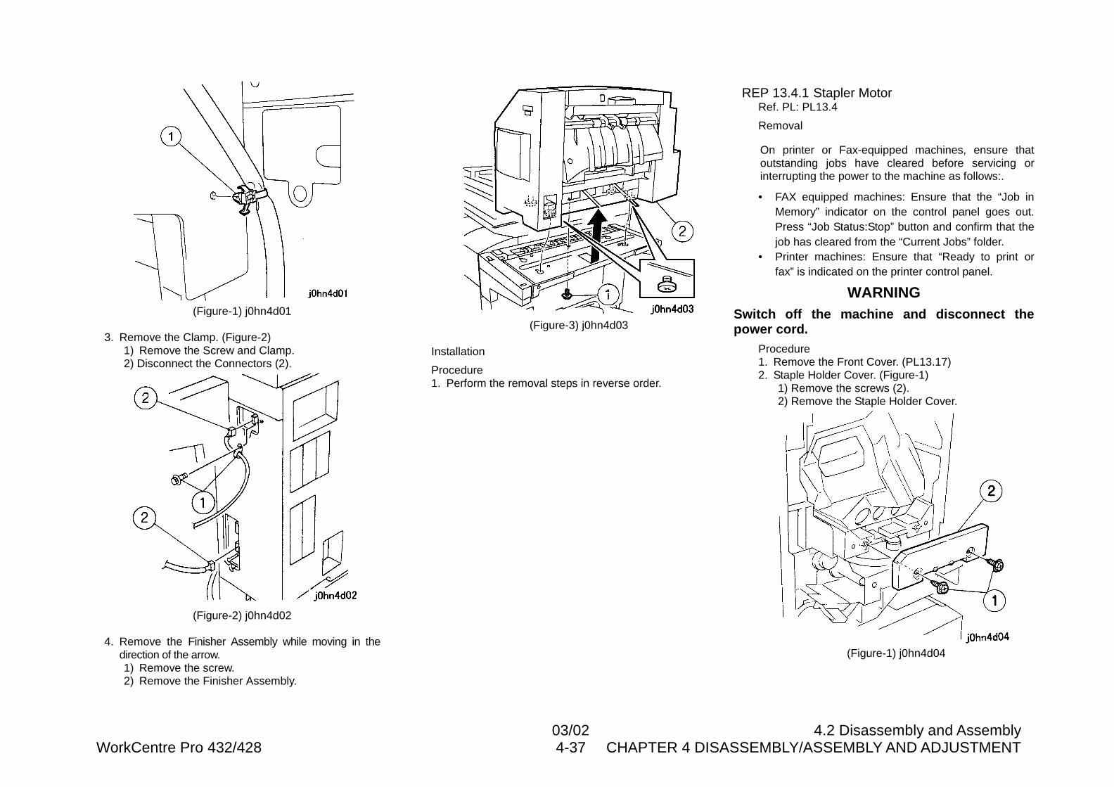
03/02 4.2 Disassembly and AssemblyWorkCentre Pro 432/428 4-37 CHAPTER 4 DISASSEMBLY/ASSEMBLY AND ADJUSTMENT
(Figure-1) j0hn4d01
3. Remove the Clamp. (Figure-2)1) Remove the Screw and Clamp.2) Disconnect the Connectors (2).
(Figure-2) j0hn4d02
4. Remove the Finisher Assembly while moving in thedirection of the arrow.1) Remove the screw.2) Remove the Finisher Assembly.
(Figure-3) j0hn4d03
Installation
Procedure1. Perform the removal steps in reverse order.
REP 13.4.1 Stapler MotorRef. PL: PL13.4
Removal
On printer or Fax-equipped machines, ensure thatoutstanding jobs have cleared before servicing orinterrupting the power to the machine as follows:.
• FAX equipped machines: Ensure that the “Job inMemory” indicator on the control panel goes out.Press “Job Status:Stop” button and confirm that thejob has cleared from the “Current Jobs” folder.
• Printer machines: Ensure that “Ready to print orfax” is indicated on the printer control panel.
WARNINGSwitch off the machine and disconnect thepower cord.
Procedure1. Remove the Front Cover. (PL13.17)2. Staple Holder Cover. (Figure-1)
1) Remove the screws (2).2) Remove the Staple Holder Cover.
(Figure-1) j0hn4d04
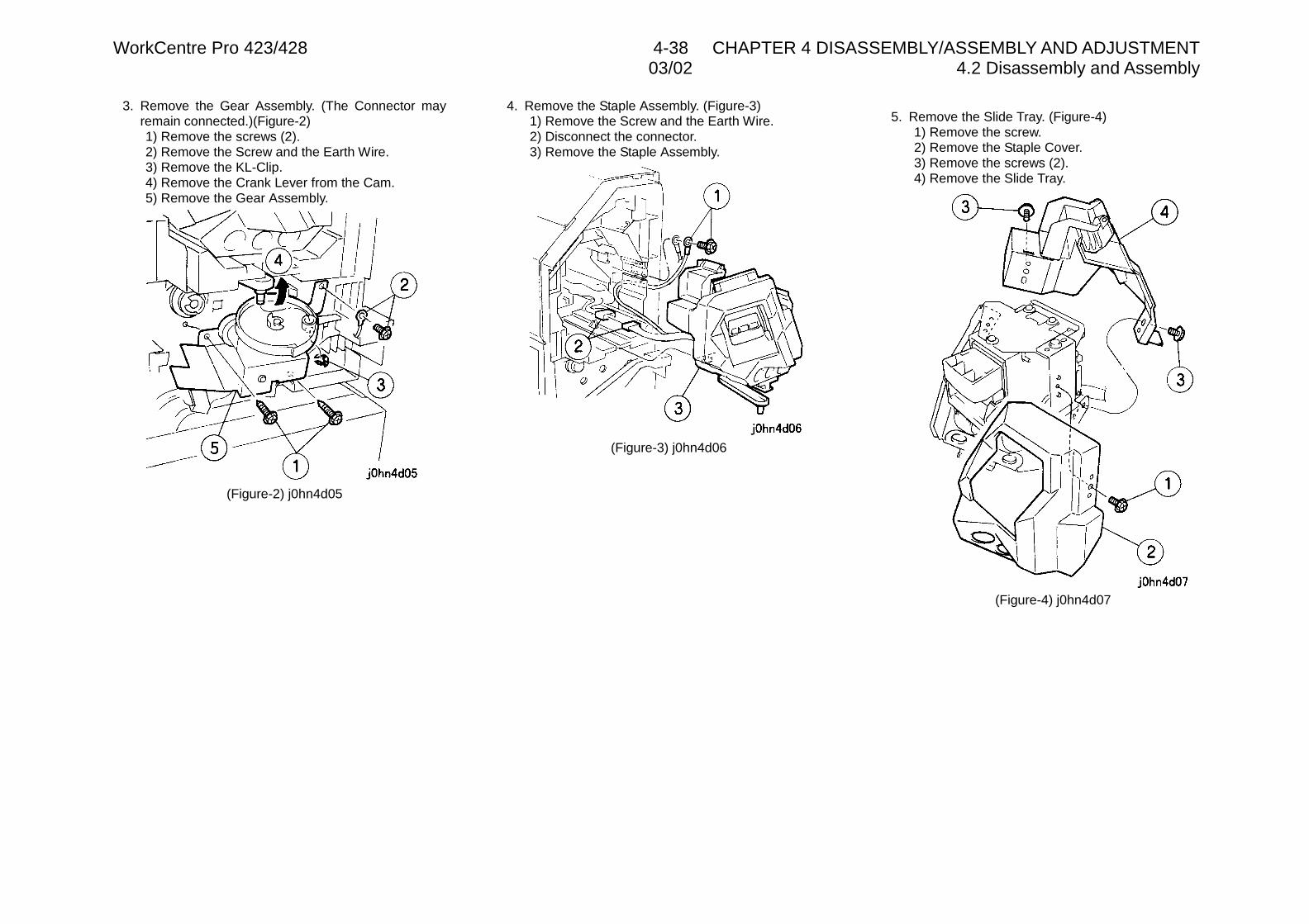
WorkCentre Pro 423/428 4-38 CHAPTER 4 DISASSEMBLY/ASSEMBLY AND ADJUSTMENT03/02 4.2 Disassembly and Assembly
3. Remove the Gear Assembly. (The Connector mayremain connected.)(Figure-2)1) Remove the screws (2).2) Remove the Screw and the Earth Wire.3) Remove the KL-Clip.4) Remove the Crank Lever from the Cam.5) Remove the Gear Assembly.
(Figure-2) j0hn4d05
4. Remove the Staple Assembly. (Figure-3)1) Remove the Screw and the Earth Wire.2) Disconnect the connector.3) Remove the Staple Assembly.
(Figure-3) j0hn4d06
5. Remove the Slide Tray. (Figure-4)1) Remove the screw.2) Remove the Staple Cover.3) Remove the screws (2).4) Remove the Slide Tray.
(Figure-4) j0hn4d07
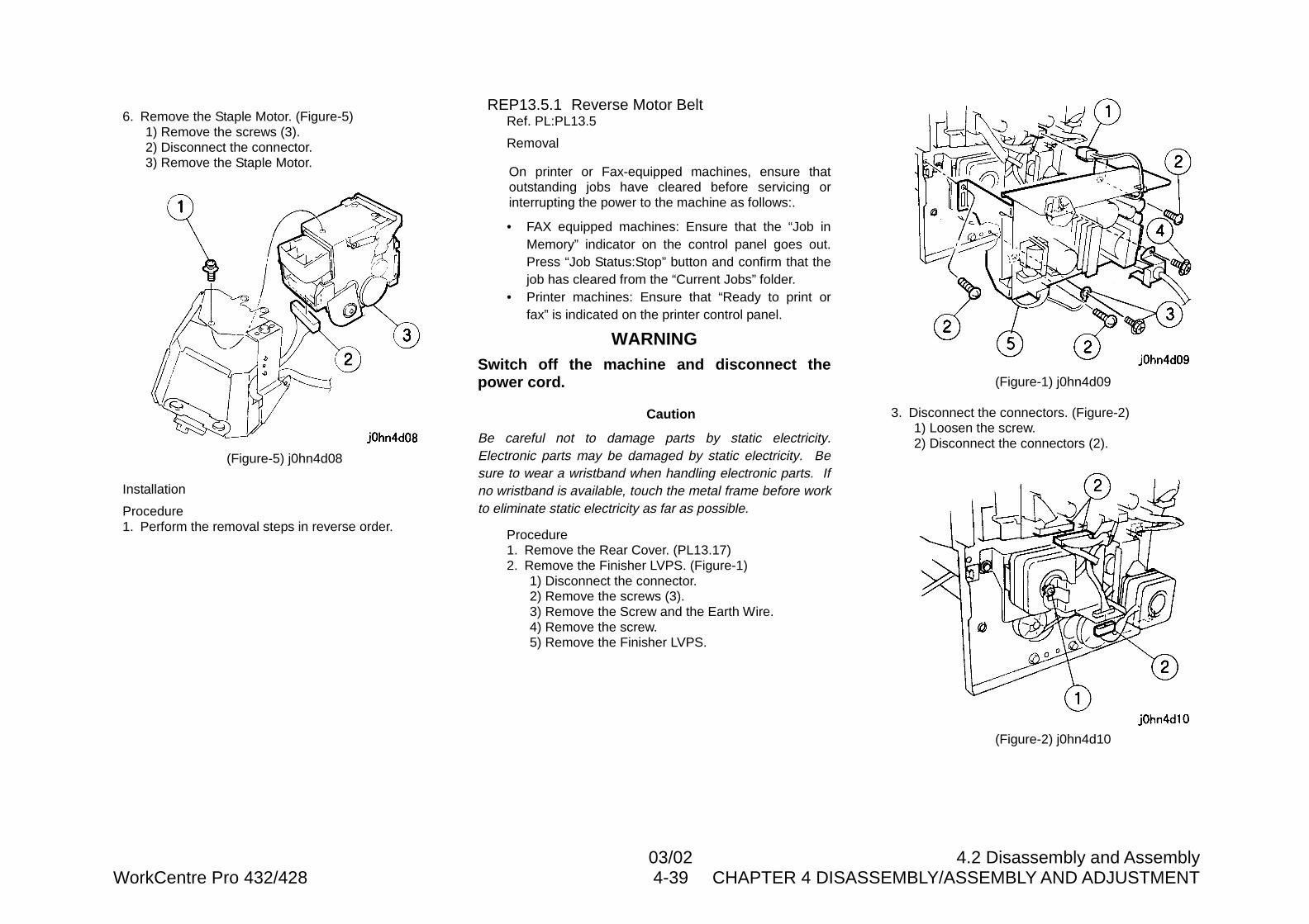
03/02 4.2 Disassembly and AssemblyWorkCentre Pro 432/428 4-39 CHAPTER 4 DISASSEMBLY/ASSEMBLY AND ADJUSTMENT
6. Remove the Staple Motor. (Figure-5)1) Remove the screws (3).2) Disconnect the connector.3) Remove the Staple Motor.
(Figure-5) j0hn4d08
Installation
Procedure1. Perform the removal steps in reverse order.
REP13.5.1 Reverse Motor BeltRef. PL:PL13.5
Removal
On printer or Fax-equipped machines, ensure thatoutstanding jobs have cleared before servicing orinterrupting the power to the machine as follows:.
• FAX equipped machines: Ensure that the “Job inMemory” indicator on the control panel goes out.Press “Job Status:Stop” button and confirm that thejob has cleared from the “Current Jobs” folder.
• Printer machines: Ensure that “Ready to print orfax” is indicated on the printer control panel.
WARNINGSwitch off the machine and disconnect thepower cord.
Caution
Be careful not to damage parts by static electricity.Electronic parts may be damaged by static electricity. Besure to wear a wristband when handling electronic parts. Ifno wristband is available, touch the metal frame before workto eliminate static electricity as far as possible.
Procedure1. Remove the Rear Cover. (PL13.17)2. Remove the Finisher LVPS. (Figure-1)
1) Disconnect the connector.2) Remove the screws (3).3) Remove the Screw and the Earth Wire.4) Remove the screw.5) Remove the Finisher LVPS.
(Figure-1) j0hn4d09
3. Disconnect the connectors. (Figure-2)1) Loosen the screw.2) Disconnect the connectors (2).
(Figure-2) j0hn4d10
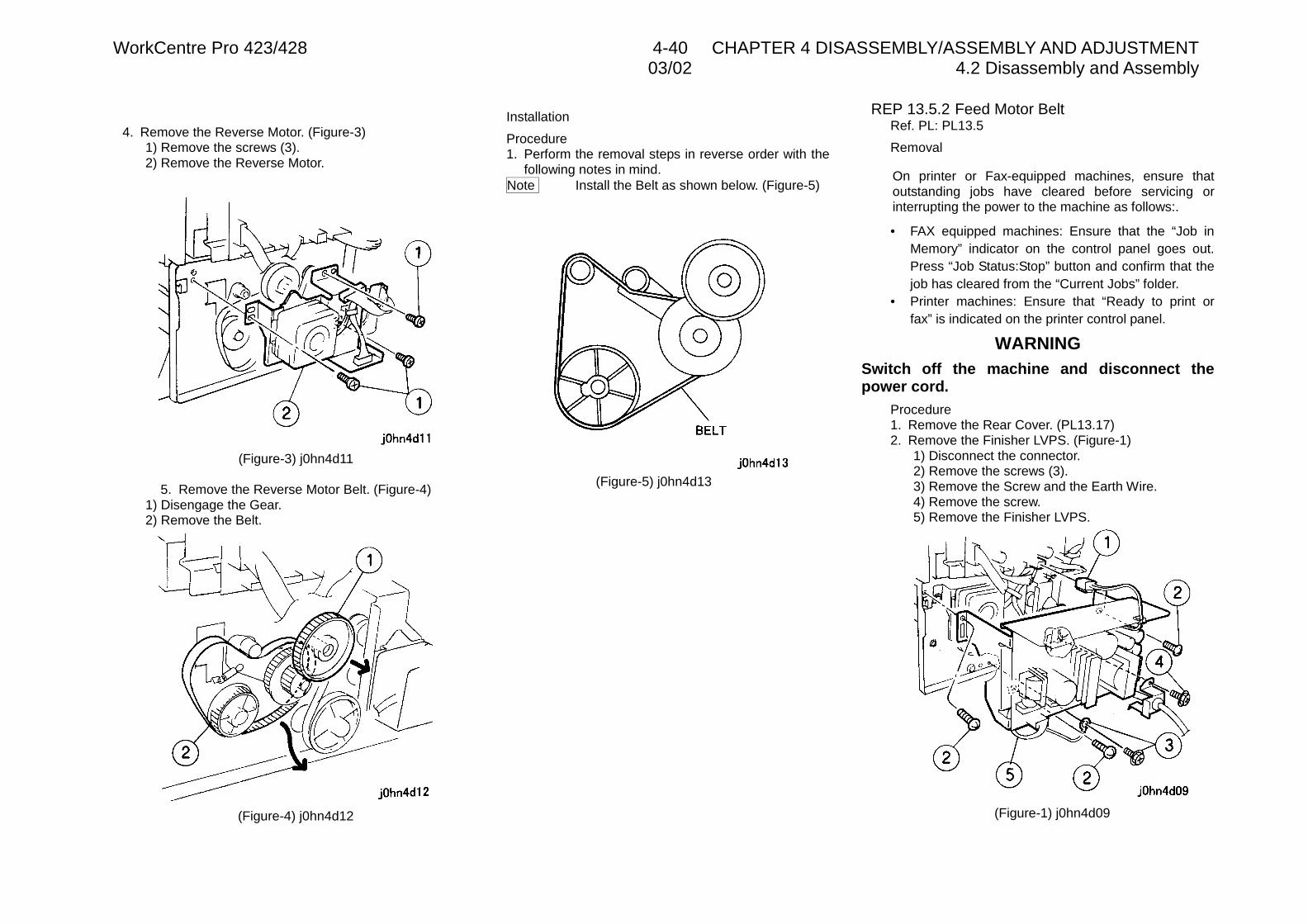
WorkCentre Pro 423/428 4-40 CHAPTER 4 DISASSEMBLY/ASSEMBLY AND ADJUSTMENT03/02 4.2 Disassembly and Assembly
4. Remove the Reverse Motor. (Figure-3)1) Remove the screws (3).2) Remove the Reverse Motor.
(Figure-3) j0hn4d11
5. Remove the Reverse Motor Belt. (Figure-4)1) Disengage the Gear.2) Remove the Belt.
(Figure-4) j0hn4d12
Installation
Procedure1. Perform the removal steps in reverse order with the
following notes in mind.Note Install the Belt as shown below. (Figure-5)
(Figure-5) j0hn4d13
REP 13.5.2 Feed Motor BeltRef. PL: PL13.5
Removal
On printer or Fax-equipped machines, ensure thatoutstanding jobs have cleared before servicing orinterrupting the power to the machine as follows:.
• FAX equipped machines: Ensure that the “Job inMemory” indicator on the control panel goes out.Press “Job Status:Stop” button and confirm that thejob has cleared from the “Current Jobs” folder.
• Printer machines: Ensure that “Ready to print orfax” is indicated on the printer control panel.
WARNINGSwitch off the machine and disconnect thepower cord.
Procedure1. Remove the Rear Cover. (PL13.17)2. Remove the Finisher LVPS. (Figure-1)
1) Disconnect the connector.2) Remove the screws (3).3) Remove the Screw and the Earth Wire.4) Remove the screw.5) Remove the Finisher LVPS.
(Figure-1) j0hn4d09
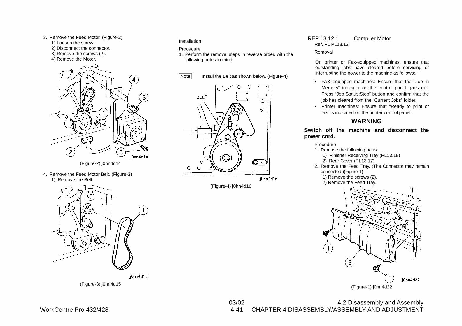
03/02 4.2 Disassembly and AssemblyWorkCentre Pro 432/428 4-41 CHAPTER 4 DISASSEMBLY/ASSEMBLY AND ADJUSTMENT
3. Remove the Feed Motor. (Figure-2)1) Loosen the screw.2) Disconnect the connector.3) Remove the screws (2).4) Remove the Motor.
(Figure-2) j0hn4d14
4. Remove the Feed Motor Belt. (Figure-3)1) Remove the Belt.
(Figure-3) j0hn4d15
Installation
Procedure1. Perform the removal steps in reverse order. with the
following notes in mind.
Note Install the Belt as shown below. (Figure-4)
(Figure-4) j0hn4d16
REP 13.12.1 Compiler MotorRef. PL PL13.12
Removal
On printer or Fax-equipped machines, ensure thatoutstanding jobs have cleared before servicing orinterrupting the power to the machine as follows:.
• FAX equipped machines: Ensure that the “Job inMemory” indicator on the control panel goes out.Press “Job Status:Stop” button and confirm that thejob has cleared from the “Current Jobs” folder.
• Printer machines: Ensure that “Ready to print orfax” is indicated on the printer control panel.
WARNINGSwitch off the machine and disconnect thepower cord.
Procedure1. Remove the following parts.
1) Finisher Receiving Tray (PL13.18)2) Rear Cover (PL13.17)
2. Remove the Feed Tray. (The Connector may remainconnected.)(Figure-1)1) Remove the screws (2).2) Remove the Feed Tray.
(Figure-1) j0hn4d22
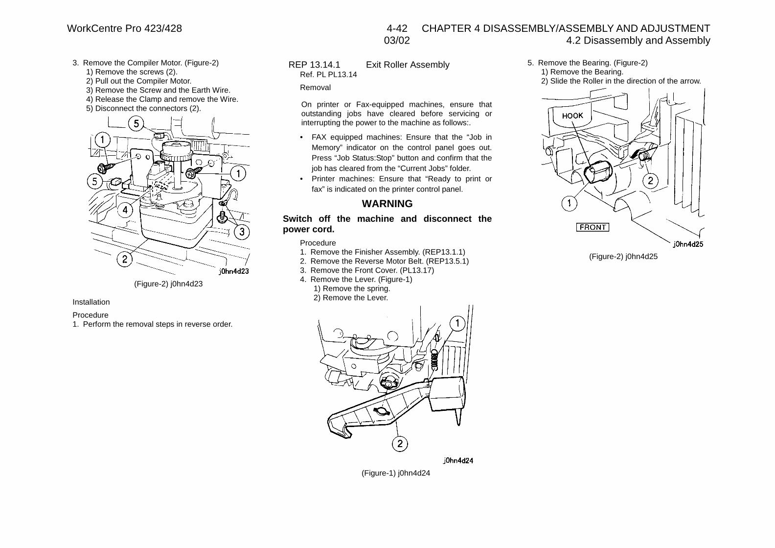
WorkCentre Pro 423/428 4-42 CHAPTER 4 DISASSEMBLY/ASSEMBLY AND ADJUSTMENT03/02 4.2 Disassembly and Assembly
3. Remove the Compiler Motor. (Figure-2)1) Remove the screws (2).2) Pull out the Compiler Motor.3) Remove the Screw and the Earth Wire.4) Release the Clamp and remove the Wire.5) Disconnect the connectors (2).
(Figure-2) j0hn4d23
Installation
Procedure1. Perform the removal steps in reverse order.
REP 13.14.1 Exit Roller AssemblyRef. PL PL13.14
Removal
On printer or Fax-equipped machines, ensure thatoutstanding jobs have cleared before servicing orinterrupting the power to the machine as follows:.
• FAX equipped machines: Ensure that the “Job inMemory” indicator on the control panel goes out.Press “Job Status:Stop” button and confirm that thejob has cleared from the “Current Jobs” folder.
• Printer machines: Ensure that “Ready to print orfax” is indicated on the printer control panel.
WARNINGSwitch off the machine and disconnect thepower cord.
Procedure1. Remove the Finisher Assembly. (REP13.1.1)2. Remove the Reverse Motor Belt. (REP13.5.1)3. Remove the Front Cover. (PL13.17)4. Remove the Lever. (Figure-1)
1) Remove the spring.2) Remove the Lever.
(Figure-1) j0hn4d24
5. Remove the Bearing. (Figure-2)1) Remove the Bearing.2) Slide the Roller in the direction of the arrow.
(Figure-2) j0hn4d25
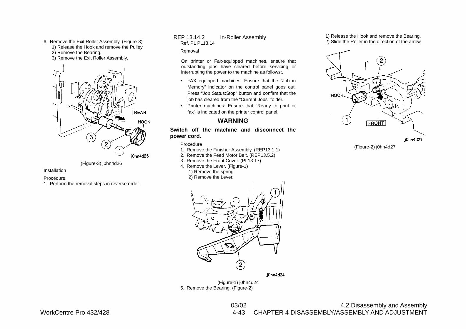
03/02 4.2 Disassembly and AssemblyWorkCentre Pro 432/428 4-43 CHAPTER 4 DISASSEMBLY/ASSEMBLY AND ADJUSTMENT
6. Remove the Exit Roller Assembly. (Figure-3)1) Release the Hook and remove the Pulley.2) Remove the Bearing.3) Remove the Exit Roller Assembly.
(Figure-3) j0hn4d26
Installation
Procedure1. Perform the removal steps in reverse order.
REP 13.14.2 In-Roller AssemblyRef. PL PL13.14
Removal
On printer or Fax-equipped machines, ensure thatoutstanding jobs have cleared before servicing orinterrupting the power to the machine as follows:.
• FAX equipped machines: Ensure that the “Job inMemory” indicator on the control panel goes out.Press “Job Status:Stop” button and confirm that thejob has cleared from the “Current Jobs” folder.
• Printer machines: Ensure that “Ready to print orfax” is indicated on the printer control panel.
WARNINGSwitch off the machine and disconnect thepower cord.
Procedure1. Remove the Finisher Assembly. (REP13.1.1)2. Remove the Feed Motor Belt. (REP13.5.2)3. Remove the Front Cover. (PL13.17)4. Remove the Lever. (Figure-1)
1) Remove the spring.2) Remove the Lever.
(Figure-1) j0hn4d245. Remove the Bearing. (Figure-2)
1) Release the Hook and remove the Bearing.2) Slide the Roller in the direction of the arrow.
(Figure-2) j0hn4d27
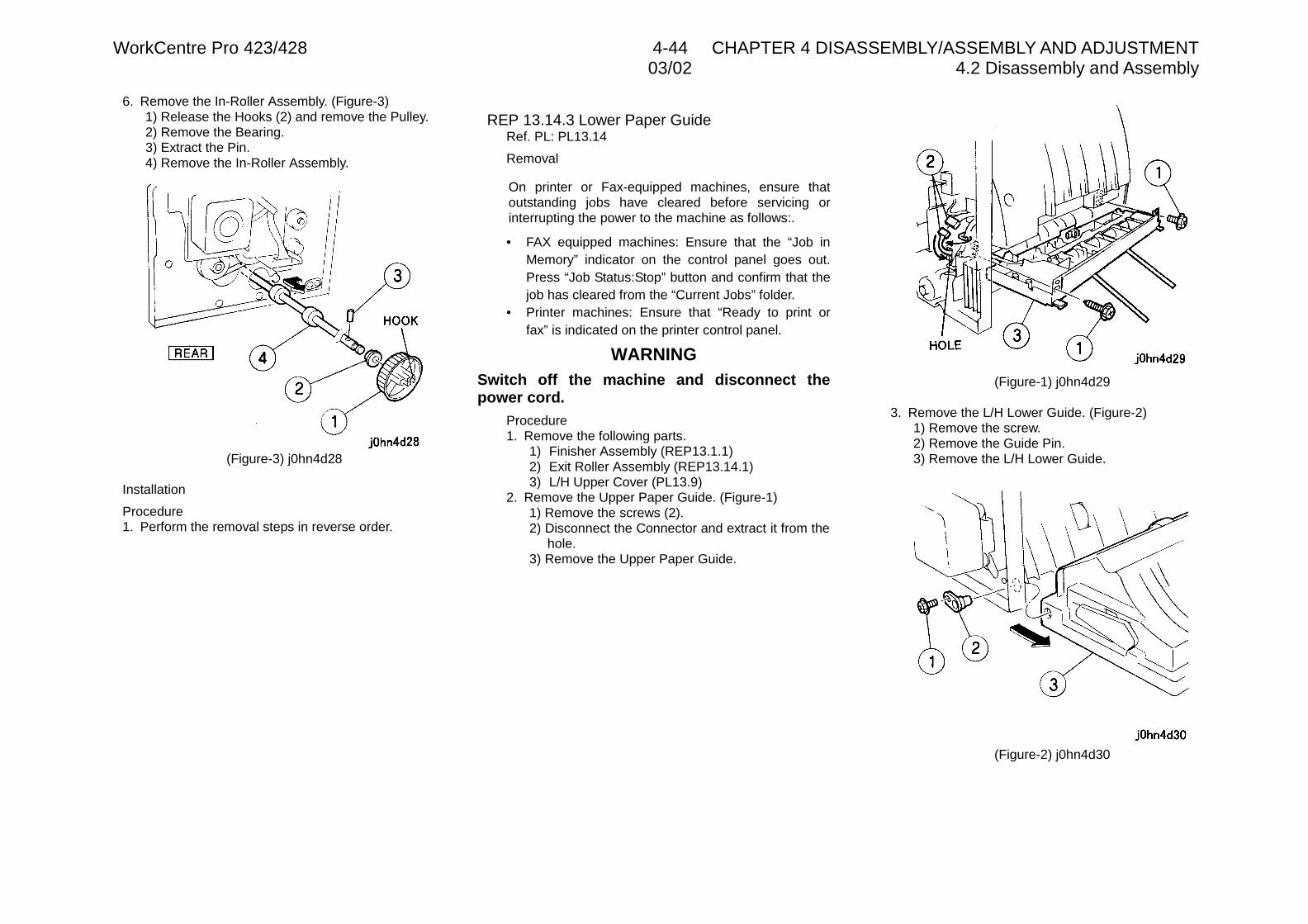
WorkCentre Pro 423/428 4-44 CHAPTER 4 DISASSEMBLY/ASSEMBLY AND ADJUSTMENT03/02 4.2 Disassembly and Assembly
6. Remove the In-Roller Assembly. (Figure-3)1) Release the Hooks (2) and remove the Pulley.2) Remove the Bearing.3) Extract the Pin.4) Remove the In-Roller Assembly.
(Figure-3) j0hn4d28
Installation
Procedure1. Perform the removal steps in reverse order.
REP 13.14.3 Lower Paper GuideRef. PL: PL13.14
Removal
On printer or Fax-equipped machines, ensure thatoutstanding jobs have cleared before servicing orinterrupting the power to the machine as follows:.
• FAX equipped machines: Ensure that the “Job inMemory” indicator on the control panel goes out.Press “Job Status:Stop” button and confirm that thejob has cleared from the “Current Jobs” folder.
• Printer machines: Ensure that “Ready to print orfax” is indicated on the printer control panel.
WARNINGSwitch off the machine and disconnect thepower cord.
Procedure1. Remove the following parts.
1) Finisher Assembly (REP13.1.1)2) Exit Roller Assembly (REP13.14.1)3) L/H Upper Cover (PL13.9)
2. Remove the Upper Paper Guide. (Figure-1)1) Remove the screws (2).2) Disconnect the Connector and extract it from the
hole.3) Remove the Upper Paper Guide.
(Figure-1) j0hn4d29
3. Remove the L/H Lower Guide. (Figure-2)1) Remove the screw.2) Remove the Guide Pin.3) Remove the L/H Lower Guide.
(Figure-2) j0hn4d30
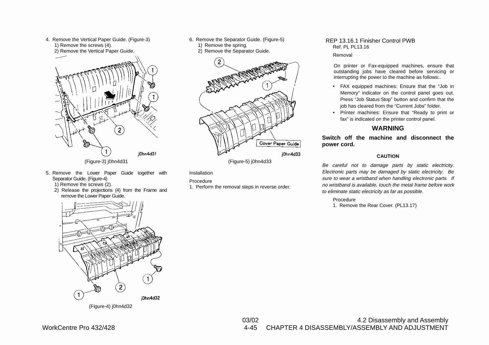
03/02 4.2 Disassembly and AssemblyWorkCentre Pro 432/428 4-45 CHAPTER 4 DISASSEMBLY/ASSEMBLY AND ADJUSTMENT
4. Remove the Vertical Paper Guide. (Figure-3)1) Remove the screws (4).2) Remove the Vertical Paper Guide.
(Figure-3) j0hn4d31
5. Remove the Lower Paper Guide together withSeparator Guide. (Figure-4)1) Remove the screws (2).2) Release the projections (4) from the Frame and
remove the Lower Paper Guide.
(Figure-4) j0hn4d32
6. Remove the Separator Guide. (Figure-5)1) Remove the spring.2) Remove the Separator Guide.
(Figure-5) j0hn4d33
Installation
Procedure1. Perform the removal steps in reverse order.
REP 13.16.1 Finisher Control PWBRef. PL PL13.16
Removal
On printer or Fax-equipped machines, ensure thatoutstanding jobs have cleared before servicing orinterrupting the power to the machine as follows:.
• FAX equipped machines: Ensure that the “Job inMemory” indicator on the control panel goes out.Press “Job Status:Stop” button and confirm that thejob has cleared from the “Current Jobs” folder.
• Printer machines: Ensure that “Ready to print orfax” is indicated on the printer control panel.
WARNINGSwitch off the machine and disconnect thepower cord.
CAUTION
Be careful not to damage parts by static electricity.Electronic parts may be damaged by static electricity. Besure to wear a wristband when handling electronic parts. Ifno wristband is available, touch the metal frame before workto eliminate static electricity as far as possible.
Procedure1. Remove the Rear Cover. (PL13.17)
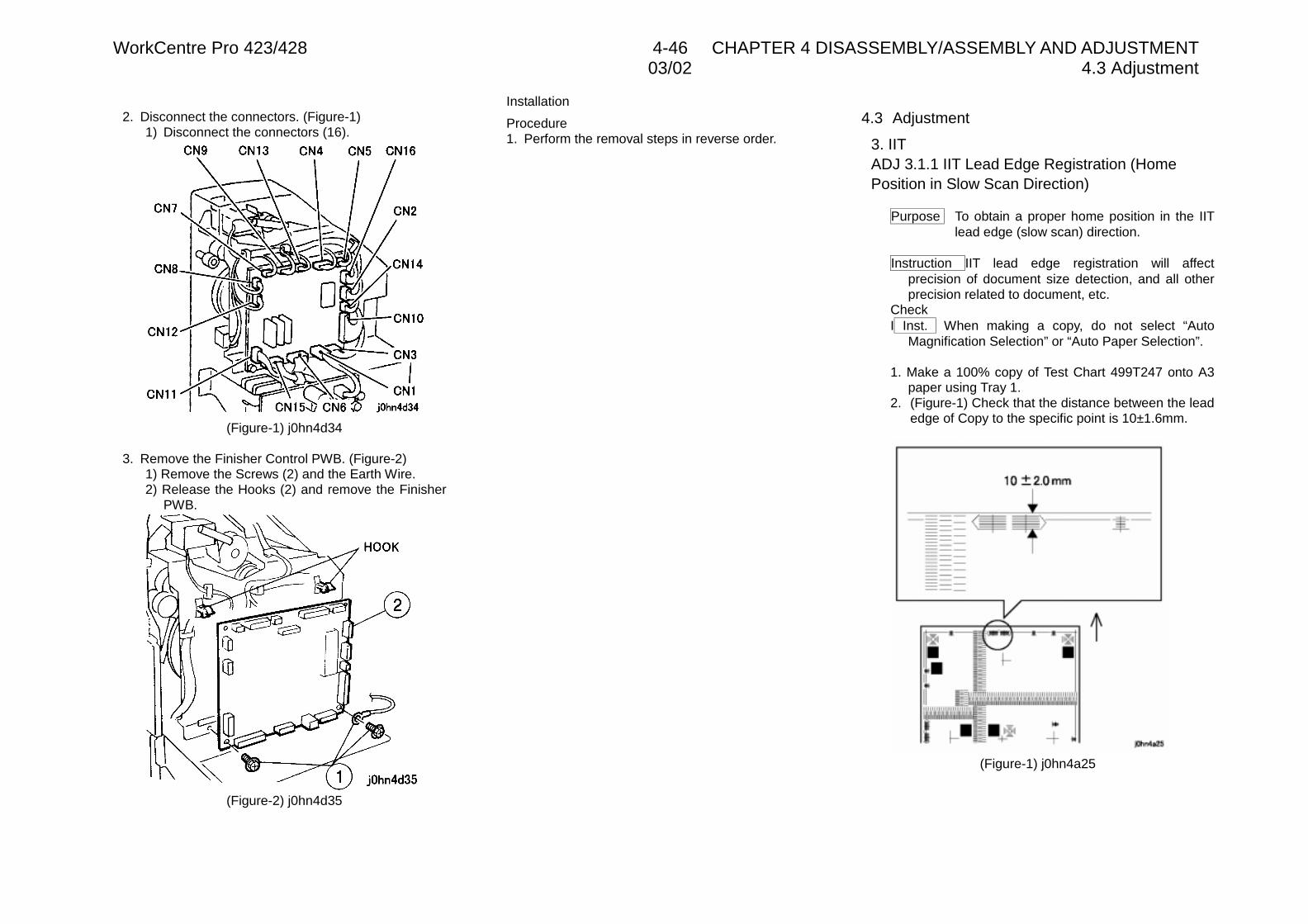
WorkCentre Pro 423/428 4-46 CHAPTER 4 DISASSEMBLY/ASSEMBLY AND ADJUSTMENT03/02 4.3 Adjustment
2. Disconnect the connectors. (Figure-1)1) Disconnect the connectors (16).
(Figure-1) j0hn4d34
3. Remove the Finisher Control PWB. (Figure-2)1) Remove the Screws (2) and the Earth Wire.2) Release the Hooks (2) and remove the Finisher
PWB.
(Figure-2) j0hn4d35
Installation
Procedure1. Perform the removal steps in reverse order.
4.3 Adjustment
3. IITADJ 3.1.1 IIT Lead Edge Registration (HomePosition in Slow Scan Direction)
Purpose To obtain a proper home position in the IITlead edge (slow scan) direction.
Instruction IIT lead edge registration will affectprecision of document size detection, and all otherprecision related to document, etc.
CheckI Inst. When making a copy, do not select “Auto
Magnification Selection” or “Auto Paper Selection”.
1. Make a 100% copy of Test Chart 499T247 onto A3paper using Tray 1.
2. (Figure-1) Check that the distance between the leadedge of Copy to the specific point is 10±1.6mm.
(Figure-1) j0hn4a25
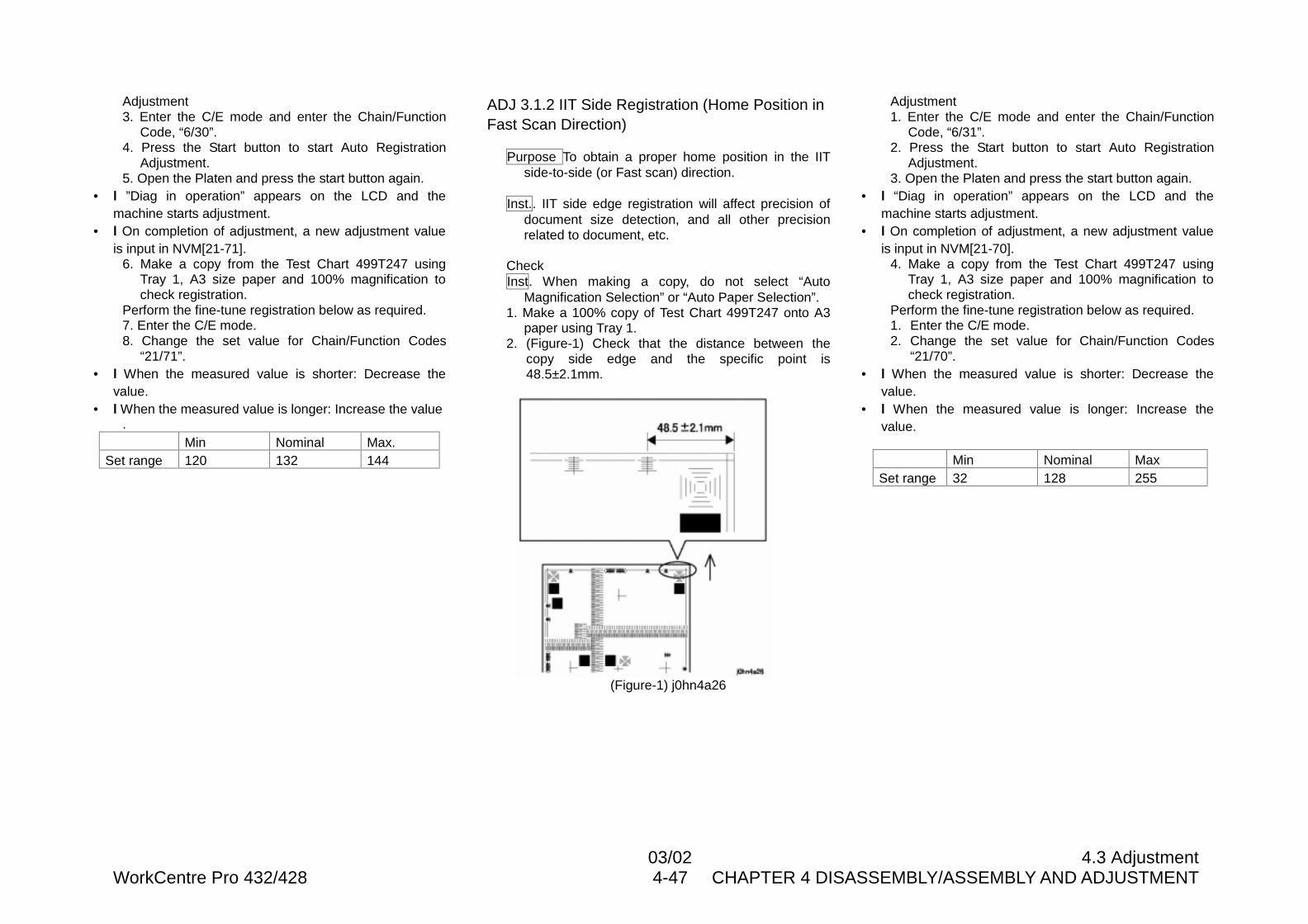
03/02 4.3 AdjustmentWorkCentre Pro 432/428 4-47 CHAPTER 4 DISASSEMBLY/ASSEMBLY AND ADJUSTMENT
Adjustment3. Enter the C/E mode and enter the Chain/Function
Code, “6/30”.4. Press the Start button to start Auto Registration
Adjustment.5. Open the Platen and press the start button again.
• l ”Diag in operation” appears on the LCD and themachine starts adjustment.
• l On completion of adjustment, a new adjustment valueis input in NVM[21-71].
6. Make a copy from the Test Chart 499T247 usingTray 1, A3 size paper and 100% magnification tocheck registration.
Perform the fine-tune registration below as required.7. Enter the C/E mode.8. Change the set value for Chain/Function Codes
“21/71”.• l When the measured value is shorter: Decrease the
value.• l When the measured value is longer: Increase the value
.Min Nominal Max.
Set range 120 132 144
ADJ 3.1.2 IIT Side Registration (Home Position inFast Scan Direction)
Purpose To obtain a proper home position in the IITside-to-side (or Fast scan) direction.
Inst.. IIT side edge registration will affect precision ofdocument size detection, and all other precisionrelated to document, etc.
CheckInst. When making a copy, do not select “Auto
Magnification Selection” or “Auto Paper Selection”.1. Make a 100% copy of Test Chart 499T247 onto A3
paper using Tray 1.2. (Figure-1) Check that the distance between the
copy side edge and the specific point is48.5±2.1mm.
(Figure-1) j0hn4a26
Adjustment1. Enter the C/E mode and enter the Chain/Function
Code, “6/31”.2. Press the Start button to start Auto Registration
Adjustment.3. Open the Platen and press the start button again.
• l “Diag in operation” appears on the LCD and themachine starts adjustment.
• l On completion of adjustment, a new adjustment valueis input in NVM[21-70].
4. Make a copy from the Test Chart 499T247 usingTray 1, A3 size paper and 100% magnification tocheck registration.
Perform the fine-tune registration below as required.1. Enter the C/E mode.2. Change the set value for Chain/Function Codes
“21/70”.• l When the measured value is shorter: Decrease the
value.• l When the measured value is longer: Increase the
value.
Min Nominal MaxSet range 32 128 255
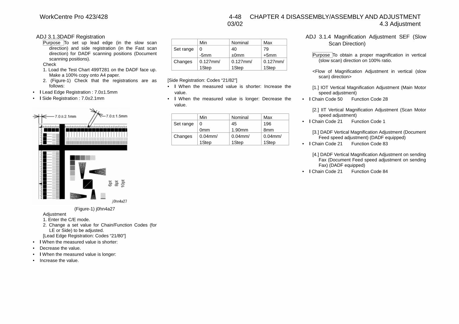
WorkCentre Pro 423/428 4-48 CHAPTER 4 DISASSEMBLY/ASSEMBLY AND ADJUSTMENT03/02 4.3 Adjustment
ADJ 3.1.3DADF RegistrationPurpose To set up lead edge (in the slow scan
direction) and side registration (in the Fast scandirection) for DADF scanning positions (Documentscanning positions).
Check1. Load the Test Chart 499T281 on the DADF face up.
Make a 100% copy onto A4 paper.2. (Figure-1) Check that the registrations are as
follows:• l Lead Edge Registration : 7.0±1.5mm• l Side Registration : 7.0±2.1mm
(Figure-1) j0hn4a27Adjustment1. Enter the C/E mode.2. Change a set value for Chain/Function Codes (for
LE or Side) to be adjusted.[Lead Edge Registration: Codes “21/80”]
• l When the measured value is shorter:• Decrease the value.• l When the measured value is longer:• Increase the value.
Min Nominal MaxSet range 0
-5mm40±0mm
79+5mm
Changes 0.127mm/1Step
0.127mm/1Step
0.127mm/1Step
[Side Registration: Codes “21/82”]• l When the measured value is shorter: Increase the
value.• l When the measured value is longer: Decrease the
value.
Min Nominal MaxSet range 0
0mm451.90mm
1968mm
Changes 0.04mm/1Step
0.04mm/1Step
0.04mm/1Step
ADJ 3.1.4 Magnification Adjustment SEF (SlowScan Direction)
Purpose To obtain a proper magnification in vertical(slow scan) direction on 100% ratio.
<Flow of Magnification Adjustment in vertical (slowscan) direction>
[1.] IOT Vertical Magnification Adjustment (Main Motorspeed adjustment)
• l Chain Code 50 Function Code 28
[2.] IIT Vertical Magnification Adjustment (Scan Motorspeed adjustment)
• l Chain Code 21 Function Code 1
[3.] DADF Vertical Magnification Adjustment (DocumentFeed speed adjustment) (DADF equipped)
• l Chain Code 21 Function Code 83
[4.] DADF Vertical Magnification Adjustment on sendingFax (Document Feed speed adjustment on sendingFax) (DADF equipped)
• l Chain Code 21 Function Code 84
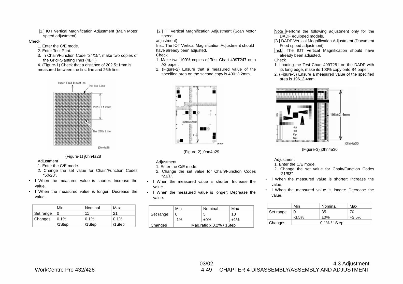
03/02 4.3 AdjustmentWorkCentre Pro 432/428 4-49 CHAPTER 4 DISASSEMBLY/ASSEMBLY AND ADJUSTMENT
[1.] IOT Vertical Magnification Adjustment (Main Motorspeed adjustment)
Check1. Enter the C/E mode.2. Enter Test Print.3. In Chain/Function Code “24/15”, make two copies of
the Grid+Slanting lines (4BIT)4. (Figure-1) Check that a distance of 202.5±1mm ismeasured between the first line and 26th line.
(Figure-1) j0hn4a28Adjustment1. Enter the C/E mode.2. Change the set value for Chain/Function Codes
“50/28”.• l When the measured value is shorter: Increase the
value.• l When the measured value is longer: Decrease the
value.
Min Nominal MaxSet range 0 11 21Changes 0.1%
/1Step0.1%/1Step
0.1%/1Step
[2.] IIT Vertical Magnification Adjustment (Scan Motorspeed
adjustment)Inst. The IOT Vertical Magnification Adjustment shouldhave already been adjusted.Check1. Make two 100% copies of Test Chart 499T247 onto
A3 paper.2. (Figure-2) Ensure that a measured value of the
specified area on the second copy is 400±3.2mm.
(Figure-2) j0hn4a29
Adjustment1. Enter the C/E mode.2. Change the set value for Chain/Function Codes
“21/1”.• l When the measured value is shorter: Increase the
value.• l When the measured value is longer: Decrease the
value.
Min Nominal MaxSet range 0
-1%5±0%
10+1%
Changes Mag.ratio x 0.2% / 1Step
Note Perform the following adjustment only for theDADF equipped models.
[3.] DADF Vertical Magnification Adjustment (DocumentFeed speed adjustment)
Inst.. The IOT Vertical Magnification should havealready been adjusted.
Check1. Loading the Test Chart 499T281 on the DADF with
its long edge, make its 100% copy onto B4 paper.2. (Figure-3) Ensure a measured value of the specified
area is 196±2.4mm.
(Figure-3) j0hn4a30
Adjustment1. Enter the C/E mode.2. Change the set value for Chain/Function Codes
“21/83”.• l When the measured value is shorter: Increase the
value.• l When the measured value is longer: Decrease the
value.
Min Nominal MaxSet range 0
-3.5%35±0%
70+3.5%
Changes 0.1% / 1Step
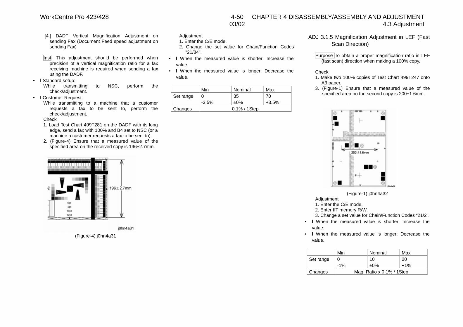
WorkCentre Pro 423/428 4-50 CHAPTER 4 DISASSEMBLY/ASSEMBLY AND ADJUSTMENT03/02 4.3 Adjustment
[4.] DADF Vertical Magnification Adjustment onsending Fax (Document Feed speed adjustment onsending Fax)
Inst. This adjustment should be performed whenprecision of a vertical magnification ratio for a faxreceiving machine is required when sending a faxusing the DADF.
• l Standard setup:While transmitting to NSC, perform the
check/adjustment.• l Customer Request:
While transmitting to a machine that a customerrequests a fax to be sent to, perform thecheck/adjustment.
Check1. Load Test Chart 499T281 on the DADF with its long
edge, send a fax with 100% and B4 set to NSC (or amachine a customer requests a fax to be sent to).
2. (Figure-4) Ensure that a measured value of thespecified area on the received copy is 196±2.7mm.
(Figure-4) j0hn4a31
Adjustment1. Enter the C/E mode.2. Change the set value for Chain/Function Codes
“21/84”.• l When the measured value is shorter: Increase the
value.• l When the measured value is longer: Decrease the
value.
Min Nominal MaxSet range 0
-3.5%35±0%
70+3.5%
Changes 0.1% / 1Step
ADJ 3.1.5 Magnification Adjustment in LEF (FastScan Direction)
Purpose To obtain a proper magnification ratio in LEF(fast scan) direction when making a 100% copy.
Check1. Make two 100% copies of Test Chart 499T247 onto
A3 paper.3. (Figure-1) Ensure that a measured value of the
specified area on the second copy is 200±1.6mm.
(Figure-1) j0hn4a32Adjustment1. Enter the C/E mode.2. Enter IIT memory R/W.3. Change a set value for Chain/Function Codes “21/2”.
• l When the measured value is shorter: Increase thevalue.
• l When the measured value is longer: Decrease thevalue.
Min Nominal MaxSet range 0
-1%10±0%
20+1%
Changes Mag. Ratio x 0.1% / 1Step
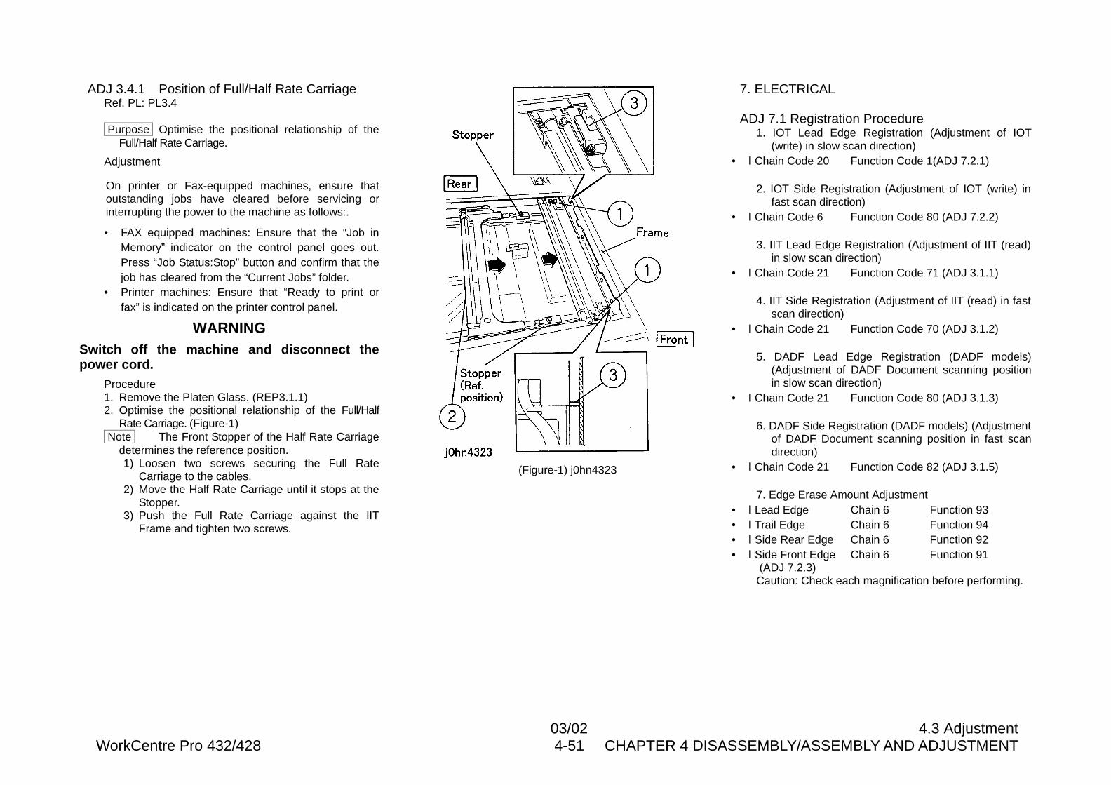
03/02 4.3 AdjustmentWorkCentre Pro 432/428 4-51 CHAPTER 4 DISASSEMBLY/ASSEMBLY AND ADJUSTMENT
ADJ 3.4.1 Position of Full/Half Rate CarriageRef. PL: PL3.4
Purpose Optimise the positional relationship of theFull/Half Rate Carriage.
Adjustment
On printer or Fax-equipped machines, ensure thatoutstanding jobs have cleared before servicing orinterrupting the power to the machine as follows:.
• FAX equipped machines: Ensure that the “Job inMemory” indicator on the control panel goes out.Press “Job Status:Stop” button and confirm that thejob has cleared from the “Current Jobs” folder.
• Printer machines: Ensure that “Ready to print orfax” is indicated on the printer control panel.
WARNINGSwitch off the machine and disconnect thepower cord.
Procedure1. Remove the Platen Glass. (REP3.1.1)2. Optimise the positional relationship of the Full/Half
Rate Carriage. (Figure-1) Note The Front Stopper of the Half Rate Carriage
determines the reference position.1) Loosen two screws securing the Full Rate
Carriage to the cables.2) Move the Half Rate Carriage until it stops at the
Stopper.3) Push the Full Rate Carriage against the IIT
Frame and tighten two screws.
(Figure-1) j0hn4323
7. ELECTRICAL
ADJ 7.1 Registration Procedure1. IOT Lead Edge Registration (Adjustment of IOT
(write) in slow scan direction)• l Chain Code 20 Function Code 1(ADJ 7.2.1)
2. IOT Side Registration (Adjustment of IOT (write) infast scan direction)
• l Chain Code 6 Function Code 80 (ADJ 7.2.2)
3. IIT Lead Edge Registration (Adjustment of IIT (read)in slow scan direction)
• l Chain Code 21 Function Code 71 (ADJ 3.1.1)
4. IIT Side Registration (Adjustment of IIT (read) in fastscan direction)
• l Chain Code 21 Function Code 70 (ADJ 3.1.2)
5. DADF Lead Edge Registration (DADF models)(Adjustment of DADF Document scanning positionin slow scan direction)
• l Chain Code 21 Function Code 80 (ADJ 3.1.3)
6. DADF Side Registration (DADF models) (Adjustmentof DADF Document scanning position in fast scandirection)
• l Chain Code 21 Function Code 82 (ADJ 3.1.5)
7. Edge Erase Amount Adjustment• l Lead Edge Chain 6 Function 93• l Trail Edge Chain 6 Function 94• l Side Rear Edge Chain 6 Function 92• l Side Front Edge Chain 6 Function 91
(ADJ 7.2.3)Caution: Check each magnification before performing.
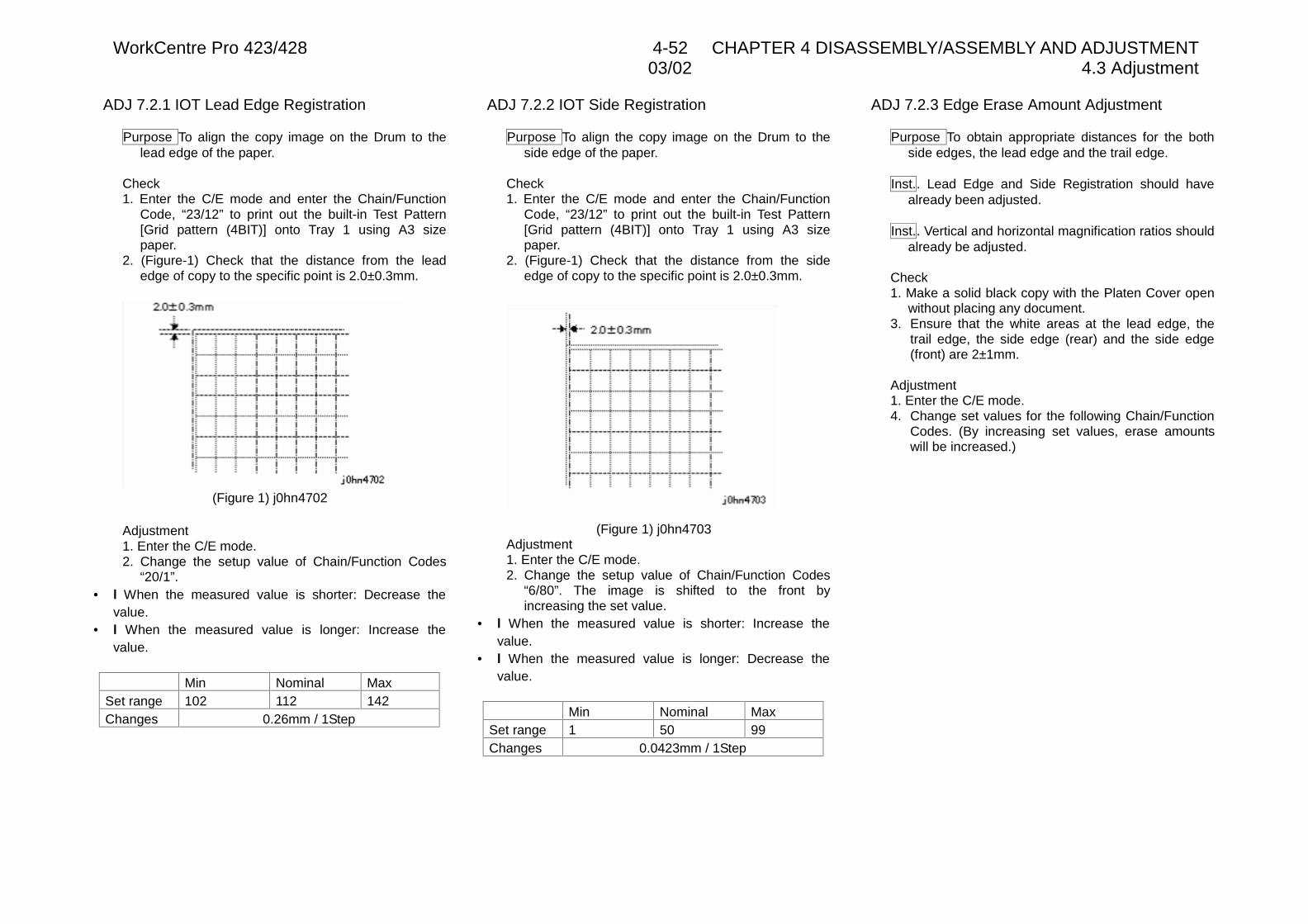
WorkCentre Pro 423/428 4-52 CHAPTER 4 DISASSEMBLY/ASSEMBLY AND ADJUSTMENT03/02 4.3 Adjustment
ADJ 7.2.1 IOT Lead Edge Registration
Purpose To align the copy image on the Drum to thelead edge of the paper.
Check1. Enter the C/E mode and enter the Chain/Function
Code, “23/12” to print out the built-in Test Pattern[Grid pattern (4BIT)] onto Tray 1 using A3 sizepaper.
2. (Figure-1) Check that the distance from the leadedge of copy to the specific point is 2.0±0.3mm.
(Figure 1) j0hn4702
Adjustment1. Enter the C/E mode.2. Change the setup value of Chain/Function Codes
“20/1”.• l When the measured value is shorter: Decrease the
value.• l When the measured value is longer: Increase the
value.
Min Nominal MaxSet range 102 112 142Changes 0.26mm / 1Step
ADJ 7.2.2 IOT Side Registration
Purpose To align the copy image on the Drum to theside edge of the paper.
Check1. Enter the C/E mode and enter the Chain/Function
Code, “23/12” to print out the built-in Test Pattern[Grid pattern (4BIT)] onto Tray 1 using A3 sizepaper.
2. (Figure-1) Check that the distance from the sideedge of copy to the specific point is 2.0±0.3mm.
(Figure 1) j0hn4703Adjustment1. Enter the C/E mode.2. Change the setup value of Chain/Function Codes
“6/80”. The image is shifted to the front byincreasing the set value.
• l When the measured value is shorter: Increase thevalue.
• l When the measured value is longer: Decrease thevalue.
Min Nominal MaxSet range 1 50 99Changes 0.0423mm / 1Step
ADJ 7.2.3 Edge Erase Amount Adjustment
Purpose To obtain appropriate distances for the bothside edges, the lead edge and the trail edge.
Inst.. Lead Edge and Side Registration should havealready been adjusted.
Inst.. Vertical and horizontal magnification ratios shouldalready be adjusted.
Check1. Make a solid black copy with the Platen Cover open
without placing any document.3. Ensure that the white areas at the lead edge, the
trail edge, the side edge (rear) and the side edge(front) are 2±1mm.
Adjustment1. Enter the C/E mode.4. Change set values for the following Chain/Function
Codes. (By increasing set values, erase amountswill be increased.)
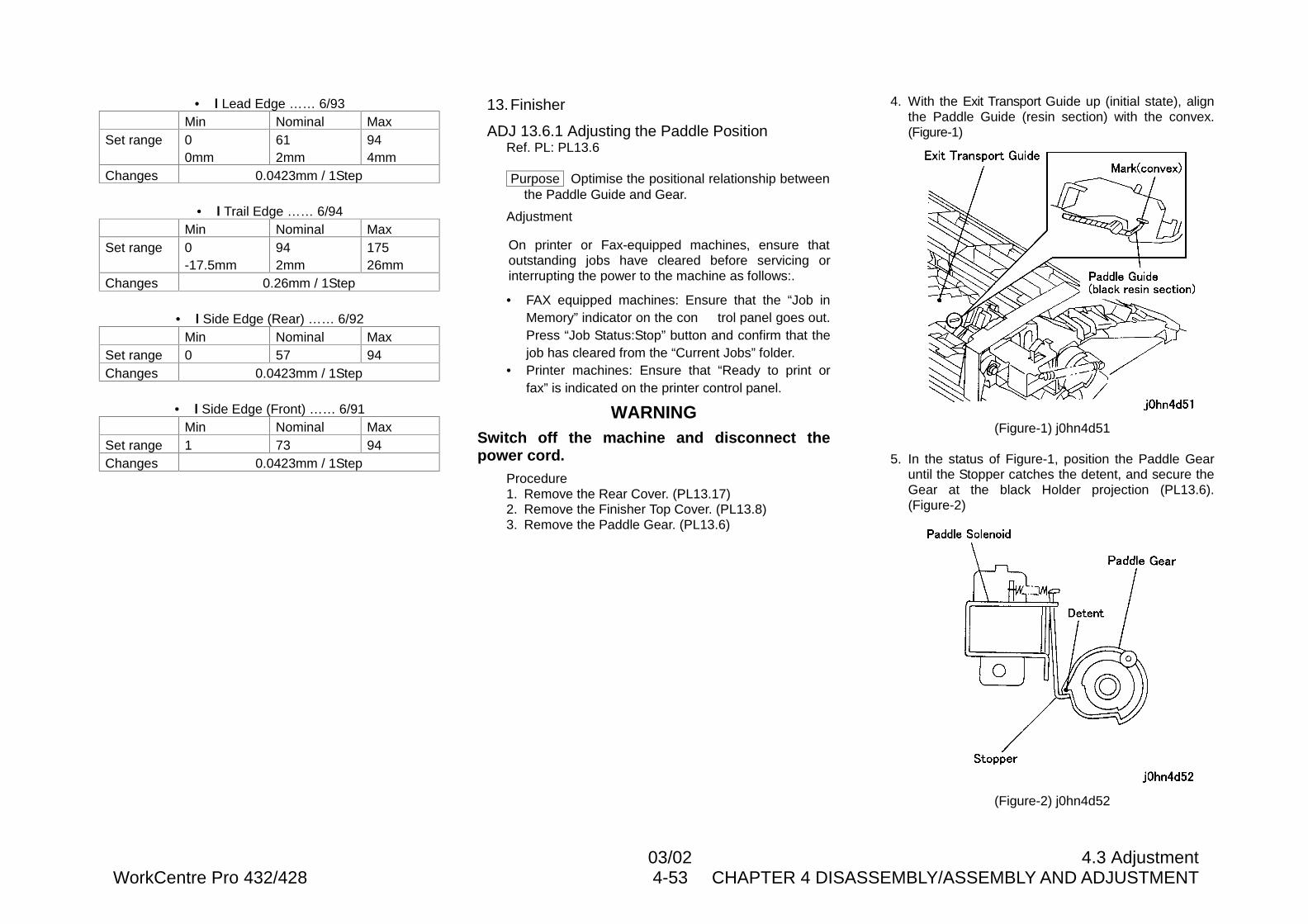
03/02 4.3 AdjustmentWorkCentre Pro 432/428 4-53 CHAPTER 4 DISASSEMBLY/ASSEMBLY AND ADJUSTMENT
• l Lead Edge …… 6/93Min Nominal Max
Set range 00mm
612mm
944mm
Changes 0.0423mm / 1Step
• l Trail Edge …… 6/94Min Nominal Max
Set range 0-17.5mm
942mm
17526mm
Changes 0.26mm / 1Step
• l Side Edge (Rear) …… 6/92Min Nominal Max
Set range 0 57 94Changes 0.0423mm / 1Step
• l Side Edge (Front) …… 6/91Min Nominal Max
Set range 1 73 94Changes 0.0423mm / 1Step
13.Finisher
ADJ 13.6.1 Adjusting the Paddle PositionRef. PL: PL13.6
Purpose Optimise the positional relationship betweenthe Paddle Guide and Gear.
Adjustment
On printer or Fax-equipped machines, ensure thatoutstanding jobs have cleared before servicing orinterrupting the power to the machine as follows:.
• FAX equipped machines: Ensure that the “Job inMemory” indicator on the con trol panel goes out.Press “Job Status:Stop” button and confirm that thejob has cleared from the “Current Jobs” folder.
• Printer machines: Ensure that “Ready to print orfax” is indicated on the printer control panel.
WARNINGSwitch off the machine and disconnect thepower cord.
Procedure1. Remove the Rear Cover. (PL13.17)2. Remove the Finisher Top Cover. (PL13.8)3. Remove the Paddle Gear. (PL13.6)
4. With the Exit Transport Guide up (initial state), alignthe Paddle Guide (resin section) with the convex.(Figure-1)
(Figure-1) j0hn4d51
5. In the status of Figure-1, position the Paddle Gearuntil the Stopper catches the detent, and secure theGear at the black Holder projection (PL13.6).(Figure-2)
(Figure-2) j0hn4d52
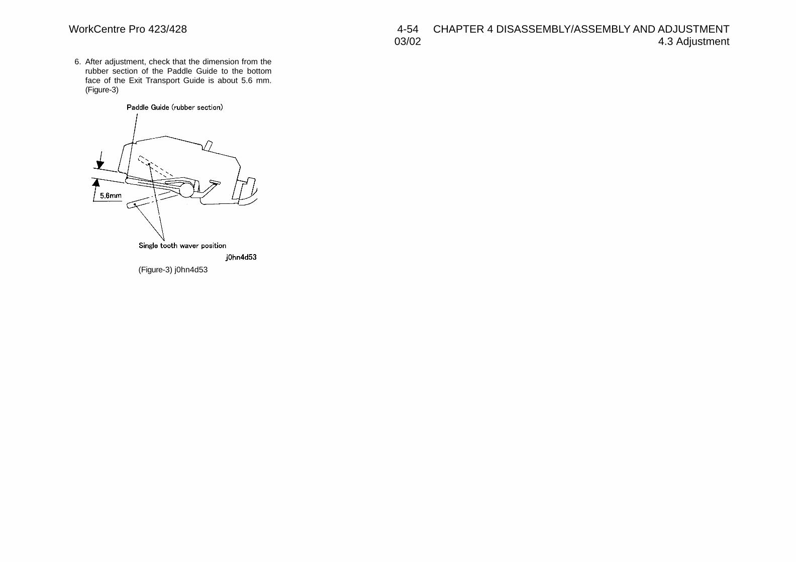
WorkCentre Pro 423/428 4-54 CHAPTER 4 DISASSEMBLY/ASSEMBLY AND ADJUSTMENT03/02 4.3 Adjustment
6. After adjustment, check that the dimension from therubber section of the Paddle Guide to the bottomface of the Exit Transport Guide is about 5.6 mm.(Figure-3)
(Figure-3) j0hn4d53

CHAPTER 5 PARTS LIST

03/02 ContentsWorkCentre Pro 423/428 5-1 CHAPTER 5 PARTS LIST
Contents
5.1 Preface............................................................................................................................ 35.1.1 How to Use Parts List.................................................................................................. 35.1.2 Notes on Using Parts List............................................................................................ 35.1.3 Plate Configuration...................................................................................................... 35.1.4 Explanation of Terms and Symbols............................................................................. 3
5.2 Parts List ......................................................................................................................... 5PL 1 Drive........................................................................................................................... 5
PL 1.1 Drive..................................................................................................................... 5PL 2 Paper Transport ......................................................................................................... 6
PL 2.1 Tray1.................................................................................................................... 6PL 2.2 Tray1 Assembly ................................................................................................... 7PL 2.3 Paper Feed (1/2) .................................................................................................. 8PL 2.4 Paper Feed (2/2) .................................................................................................. 9PL 2.5 T/A Chute Assembly........................................................................................... 10PL 2.6 R/H Chute Assembly.......................................................................................... 11PL 2.7 Exit Assembly .................................................................................................... 12PL 2.8 OCT Assembly (1/3)........................................................................................... 13PL 2.9 OCT Assembly (2/3)........................................................................................... 14PL 2.10 OCT Assembly (3/3)......................................................................................... 15PL 2.11 Registration ...................................................................................................... 16PL 2.12 Registration Chute Assembly........................................................................... 17
PL 3 IIT............................................................................................................................. 18PL 3.1 Platen Glass and IPS PWB................................................................................ 18PL 3.2 Lens Assembly and CCD PWB.......................................................................... 19PL 3.3 Carriage Motor and Carriage Cable ................................................................... 20PL 3.4 Full Rate Carriage and Half Carriage ................................................................. 21PL 3.5 Platen Cover ...................................................................................................... 22PL 3.6 Top Cover, Control Panel ................................................................................... 23PL 3.7 Touch Panel, Handset ........................................................................................ 24
PL 4 ROS ......................................................................................................................... 25PL 4.1 ROS ................................................................................................................... 25
PL 5 XERO/DEVE ............................................................................................................ 26PL 5.1 XERO/DEVE (1/2).............................................................................................. 26PL 5.2 XERO/DEVE (2/2).............................................................................................. 27
PL 6 Fuser........................................................................................................................ 28PL 6.1 Fuser Assembly (1/2) ......................................................................................... 28PL 6.2 Fuser Assembly (2/2) ......................................................................................... 29
PL 7 Electrical................................................................................................................... 30PL 7.1 IOT Electrical (1/2) ............................................................................................. 30PL 7.2 IOT Electrical (2/2) ............................................................................................. 31PL 7.3 MF Box (1/2) ...................................................................................................... 32
PL 7.4 MF Box (2/2) ...................................................................................................... 33PL 7.5 ESS Box............................................................................................................. 34PL 7.6 ESS Option ........................................................................................................ 35
PL 8 Cover ....................................................................................................................... 36PL 8.1 Cover-Top, Control Panel................................................................................... 36PL 8.2 Cover-Front........................................................................................................ 37PL 8.3 Cover-Rear/Right ............................................................................................... 38
PL 9 Cabinet..................................................................................................................... 39PL 9.1 Feed Motor, PWB............................................................................................... 39PL 9.2 T/A Roller ........................................................................................................... 40PL 9.3 Switch PWB, Sensor .......................................................................................... 41PL 9.4 Right Cover Assembly........................................................................................ 42PL 9.5 Option Box Assembly......................................................................................... 43PL 9.6 Tray 2/3/4 Assembly .......................................................................................... 44PL 9.7 Tray (1/3)............................................................................................................ 45PL 9.8 Tray (2/3)............................................................................................................ 46PL 9.9 Tray (3/3)............................................................................................................ 47PL 9.10 Cover ............................................................................................................... 48
PL 10 DADF ..................................................................................................................... 49PL 10.1 DADF Assembly............................................................................................... 49PL 10.2 DADF Feeder Assembly .................................................................................. 50PL 10.3 Base Cover, Counter Balance.......................................................................... 51PL 10.4 Top Cover Assembly (1/2)................................................................................ 52PL 10.5 Top Cover Assembly (2/2)................................................................................ 53PL 10.6 Chute, Regi Roller............................................................................................ 54PL 10.7 Exit Roller, Read Roller .................................................................................... 55PL 10.8 DADF Feed/Drive Motor................................................................................... 56PL 10.9 Document Tray (DMO-E) ................................................................................. 57PL 10.10 Document Tray (DMO-W/OSG) ..................................................................... 58
PL 11 MSI......................................................................................................................... 59PL 11.1 MSI Assembly .................................................................................................. 59PL 11.2 MSI Tray........................................................................................................... 60PL 11.3 Base Tray ......................................................................................................... 61PL 11.4 Feed/Retard Roller ........................................................................................... 62
PL 12 Duplex.................................................................................................................... 63PL 12.1 Duplex.............................................................................................................. 63
PL 13 Finisher .................................................................................................................. 64PL 13.1 Finisher Assembly............................................................................................ 64PL 13.2 Front Side Switch/Sensor................................................................................. 65PL 13.3 Stapler Assembly, Base Cover ......................................................................... 66PL 13.4 Stapler Motor.................................................................................................... 67PL 13.5 Reverse/Feed Motor ........................................................................................ 68PL 13.6 Paddle Solenoid, Exit Roller Assembly ............................................................ 69PL 13.7 Transfer Motor, C Paper Guide ........................................................................ 70PL 13.8 Top Cover, FT Paper Guide ............................................................................. 71PL 13.9 L/H Upper Cover .............................................................................................. 72
WorkCentre Pro 423/428 5-2 CHAPTER 5 PARTS LIST03/02 Contents
PL 13.10 Exit Transport Base Guide ............................................................................. 73PL 13.11 L/H Lower Cover ............................................................................................ 74PL 13.12 Compiler Motor............................................................................................... 75PL 13.13 R/H Cover ...................................................................................................... 76PL 13.14 Exit Roller Assembly ...................................................................................... 77PL 13.15 Upper Paper Guide ........................................................................................ 78PL 13.16 Finisher LVPS ................................................................................................ 79PL 13.17 Front/Rear Cover, Switch PWB...................................................................... 80PL 13.18 Finisher Receiving Tray.................................................................................. 81PL 13.19 Finisher Side Tray .......................................................................................... 82PL 14.1 Consumables and Special Tools ...................................................................... 83
5.3 Common Hardware ....................................................................................................... 84
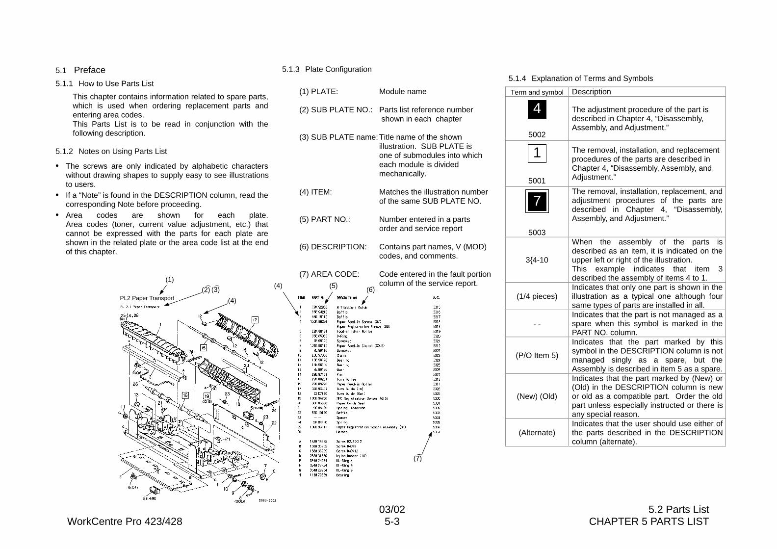
03/02 5.2 Parts ListWorkCentre Pro 423/428 5-3 CHAPTER 5 PARTS LIST
5.1 Preface5.1.1 How to Use Parts List
This chapter contains information related to spare parts,which is used when ordering replacement parts andentering area codes.This Parts List is to be read in conjunction with thefollowing description.
5.1.2 Notes on Using Parts List
• The screws are only indicated by alphabetic characterswithout drawing shapes to supply easy to see illustrationsto users.
• If a “Note” is found in the DESCRIPTION column, read thecorresponding Note before proceeding.
• Area codes are shown for each plate.Area codes (toner, current value adjustment, etc.) thatcannot be expressed with the parts for each plate areshown in the related plate or the area code list at the endof this chapter.
5.1.3 Plate Configuration
(1) PLATE: Module name
(2) SUB PLATE NO.: Parts list reference number shown in each chapter
(3) SUB PLATE name:Title name of the shownillustration. SUB PLATE isone of submodules into whicheach module is dividedmechanically.
(4) ITEM: Matches the illustration numberof the same SUB PLATE NO.
(5) PART NO.: Number entered in a partsorder and service report
(6) DESCRIPTION: Contains part names, V (MOD)codes, and comments.
(7) AREA CODE: Code entered in the fault portioncolumn of the service report.
5.1.4 Explanation of Terms and Symbols
Term and symbol Description
5002
The adjustment procedure of the part isdescribed in Chapter 4, “Disassembly,Assembly, and Adjustment.”
5001
The removal, installation, and replacementprocedures of the parts are described inChapter 4, “Disassembly, Assembly, andAdjustment.”
5003
The removal, installation, replacement, andadjustment procedures of the parts aredescribed in Chapter 4, “Disassembly,Assembly, and Adjustment.”
3{4-10
When the assembly of the parts isdescribed as an item, it is indicated on theupper left or right of the illustration.This example indicates that item 3described the assembly of items 4 to 1.
(1/4 pieces)Indicates that only one part is shown in theillustration as a typical one although foursame types of parts are installed in all.
- -Indicates that the part is not managed as aspare when this symbol is marked in thePART NO. column.
(P/O Item 5)
Indicates that the part marked by thissymbol in the DESCRIPTION column is notmanaged singly as a spare, but theAssembly is described in item 5 as a spare.
(New) (Old)
Indicates that the part marked by (New) or(Old) in the DESCRIPTION column is newor old as a compatible part. Order the oldpart unless especially instructed or there isany special reason.
(Alternate)Indicates that the user should use either ofthe parts described in the DESCRIPTIONcolumn (alternate).
1
2 3
4
4 56
7
4
1
7
PL2 Paper Transport
(1)
(2)
(4)
(3)(4) (5) (6)
(7)
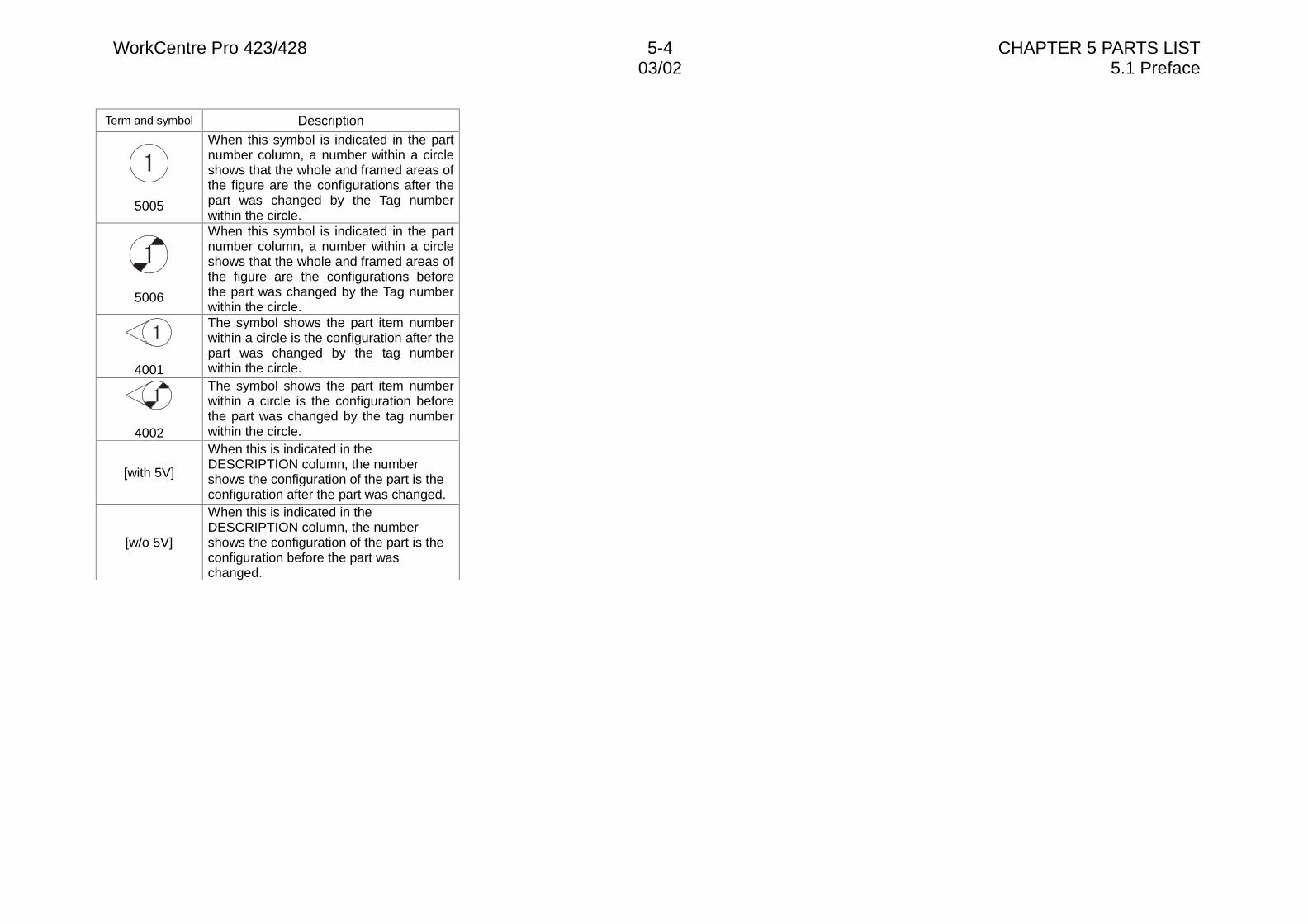
WorkCentre Pro 423/428 5-4 CHAPTER 5 PARTS LIST03/02 5.1 Preface
Term and symbol Description
5005
When this symbol is indicated in the partnumber column, a number within a circleshows that the whole and framed areas ofthe figure are the configurations after thepart was changed by the Tag numberwithin the circle.
5006
When this symbol is indicated in the partnumber column, a number within a circleshows that the whole and framed areas ofthe figure are the configurations beforethe part was changed by the Tag numberwithin the circle.
4001
The symbol shows the part item numberwithin a circle is the configuration after thepart was changed by the tag numberwithin the circle.
4002
The symbol shows the part item numberwithin a circle is the configuration beforethe part was changed by the tag numberwithin the circle.
[with 5V]
When this is indicated in theDESCRIPTION column, the numbershows the configuration of the part is theconfiguration after the part was changed.
[w/o 5V]
When this is indicated in theDESCRIPTION column, the numbershows the configuration of the part is theconfiguration before the part waschanged.
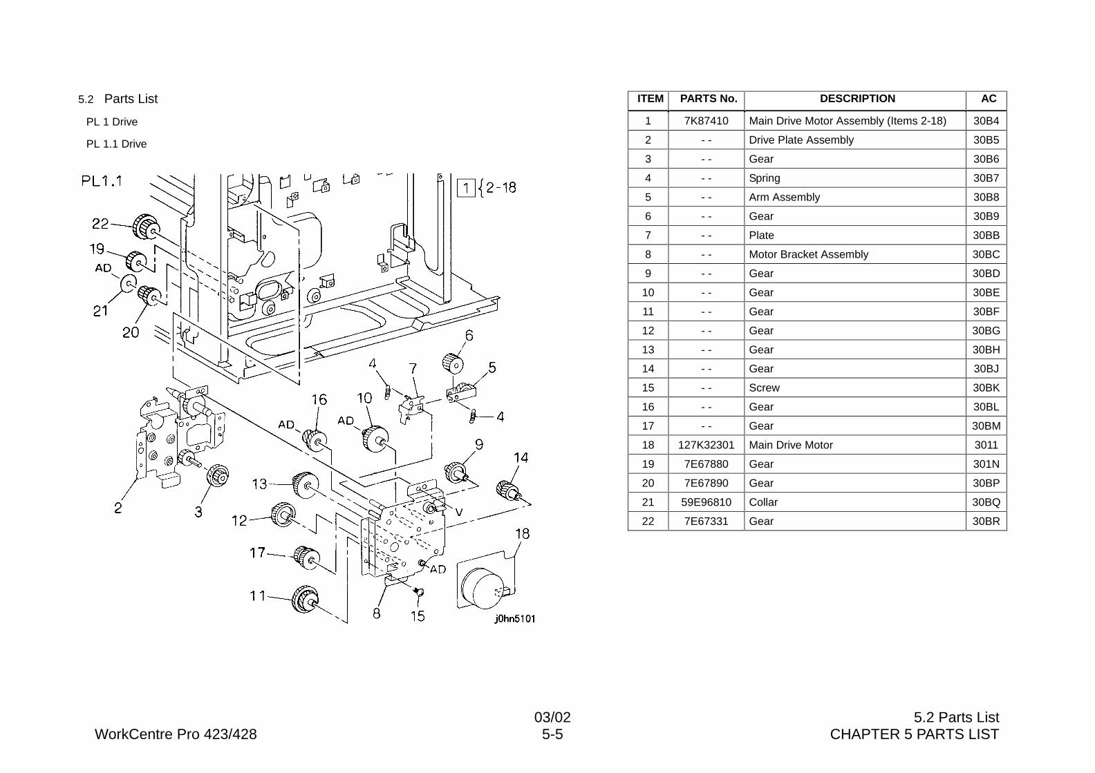
03/02 5.2 Parts ListWorkCentre Pro 423/428 5-5 CHAPTER 5 PARTS LIST
5.2 Parts List
PL 1 Drive
PL 1.1 Drive
ITEM PARTS No. DESCRIPTION AC
1 7K87410 Main Drive Motor Assembly (Items 2-18) 30B4
2 - - Drive Plate Assembly 30B5
3 - - Gear 30B6
4 - - Spring 30B7
5 - - Arm Assembly 30B8
6 - - Gear 30B9
7 - - Plate 30BB
8 - - Motor Bracket Assembly 30BC
9 - - Gear 30BD
10 - - Gear 30BE
11 - - Gear 30BF
12 - - Gear 30BG
13 - - Gear 30BH
14 - - Gear 30BJ
15 - - Screw 30BK
16 - - Gear 30BL
17 - - Gear 30BM
18 127K32301 Main Drive Motor 3011
19 7E67880 Gear 301N
20 7E67890 Gear 30BP
21 59E96810 Collar 30BQ
22 7E67331 Gear 30BR
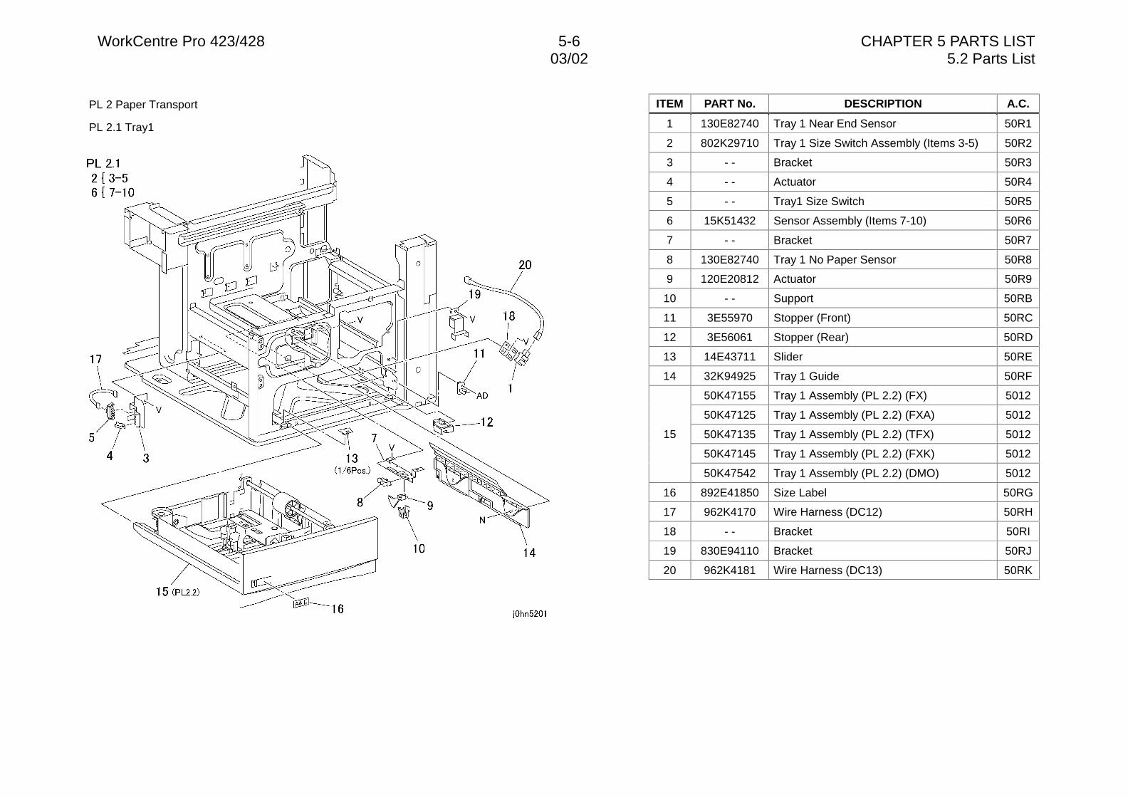
WorkCentre Pro 423/428 5-6 CHAPTER 5 PARTS LIST03/02 5.2 Parts List
PL 2 Paper Transport
PL 2.1 Tray1
ITEM PART No. DESCRIPTION A.C.
1 130E82740 Tray 1 Near End Sensor 50R1
2 802K29710 Tray 1 Size Switch Assembly (Items 3-5) 50R2
3 - - Bracket 50R3
4 - - Actuator 50R4
5 - - Tray1 Size Switch 50R5
6 15K51432 Sensor Assembly (Items 7-10) 50R6
7 - - Bracket 50R7
8 130E82740 Tray 1 No Paper Sensor 50R8
9 120E20812 Actuator 50R9
10 - - Support 50RB
11 3E55970 Stopper (Front) 50RC
12 3E56061 Stopper (Rear) 50RD
13 14E43711 Slider 50RE
14 32K94925 Tray 1 Guide 50RF
50K47155 Tray 1 Assembly (PL 2.2) (FX) 5012
50K47125 Tray 1 Assembly (PL 2.2) (FXA) 5012
50K47135 Tray 1 Assembly (PL 2.2) (TFX) 5012
50K47145 Tray 1 Assembly (PL 2.2) (FXK) 5012
15
50K47542 Tray 1 Assembly (PL 2.2) (DMO) 5012
16 892E41850 Size Label 50RG
17 962K4170 Wire Harness (DC12) 50RH
18 - - Bracket 50RI
19 830E94110 Bracket 50RJ
20 962K4181 Wire Harness (DC13) 50RK
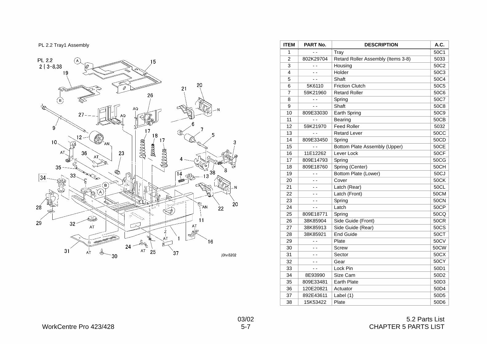
03/02 5.2 Parts ListWorkCentre Pro 423/428 5-7 CHAPTER 5 PARTS LIST
PL 2.2 Tray1 Assembly ITEM PART No. DESCRIPTION A.C.
1 - - Tray 50C12 802K29704 Retard Roller Assembly (Items 3-8) 50333 - - Housing 50C24 - - Holder 50C35 - - Shaft 50C46 5K6110 Friction Clutch 50C57 59K21960 Retard Roller 50C68 - - Spring 50C79 - - Shaft 50C8
10 809E33030 Earth Spring 50C911 - - Bearing 50CB12 59K21970 Feed Roller 503213 - - Retard Lever 50CC14 809E33450 Spring 50CD15 - - Bottom Plate Assembly (Upper) 50CE16 11E12262 Lever Lock 50CF17 809E14793 Spring 50CG18 809E18760 Spring (Center) 50CH19 - - Bottom Plate (Lower) 50CJ20 - - Cover 50CK21 - - Latch (Rear) 50CL22 - - Latch (Front) 50CM23 - - Spring 50CN24 - - Latch 50CP25 809E18771 Spring 50CQ26 38K85904 Side Guide (Front) 50CR27 38K85913 Side Guide (Rear) 50CS28 38K85921 End Guide 50CT29 - - Plate 50CV30 - - Screw 50CW31 - - Sector 50CX
32 - - Gear 50CY
33 - - Lock Pin 50D134 8E93990 Size Cam 50D235 809E33481 Earth Plate 50D336 120E20821 Actuator 50D437 892E43611 Label (1) 50D538 15K53422 Plate 50D6
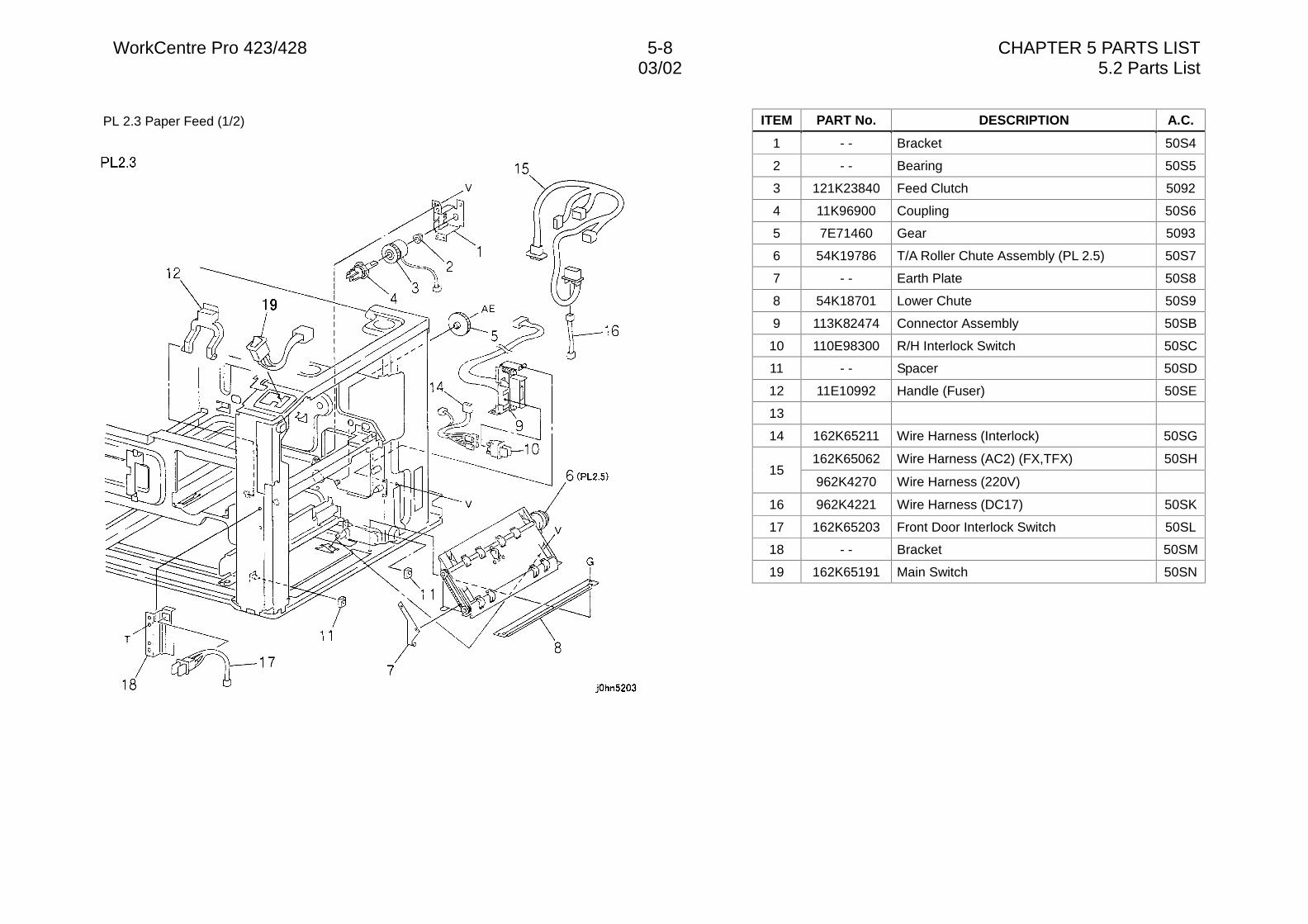
WorkCentre Pro 423/428 5-8 CHAPTER 5 PARTS LIST03/02 5.2 Parts List
PL 2.3 Paper Feed (1/2) ITEM PART No. DESCRIPTION A.C.
1 - - Bracket 50S4
2 - - Bearing 50S5
3 121K23840 Feed Clutch 5092
4 11K96900 Coupling 50S6
5 7E71460 Gear 5093
6 54K19786 T/A Roller Chute Assembly (PL 2.5) 50S7
7 - - Earth Plate 50S8
8 54K18701 Lower Chute 50S9
9 113K82474 Connector Assembly 50SB
10 110E98300 R/H Interlock Switch 50SC
11 - - Spacer 50SD
12 11E10992 Handle (Fuser) 50SE
13
14 162K65211 Wire Harness (Interlock) 50SG
162K65062 Wire Harness (AC2) (FX,TFX) 50SH15
962K4270 Wire Harness (220V)
16 962K4221 Wire Harness (DC17) 50SK
17 162K65203 Front Door Interlock Switch 50SL
18 - - Bracket 50SM
19 162K65191 Main Switch 50SN
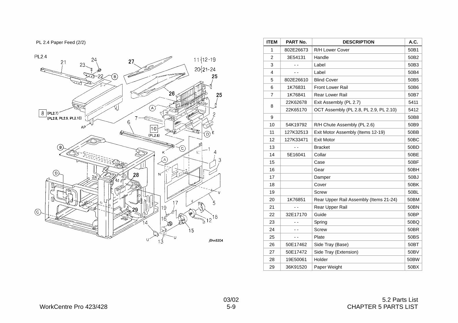
03/02 5.2 Parts ListWorkCentre Pro 423/428 5-9 CHAPTER 5 PARTS LIST
PL 2.4 Paper Feed (2/2) ITEM PART No. DESCRIPTION A.C.
1 802E26673 R/H Lower Cover 50B1
2 3E54131 Handle 50B2
3 - - Label 50B3
4 - - Label 50B4
5 802E26610 Blind Cover 50B5
6 1K76831 Front Lower Rail 50B6
7 1K76841 Rear Lower Rail 50B7
22K62678 Exit Assembly (PL 2.7) 54118
22K65170 OCT Assembly (PL 2.8, PL 2.9, PL 2.10) 5412
9 50B8
10 54K19792 R/H Chute Assembly (PL 2.6) 50B9
11 127K32513 Exit Motor Assembly (Items 12-19) 50BB
12 127K33471 Exit Motor 50BC
13 - - Bracket 50BD
14 5E16041 Collar 50BE
15 Case 50BF
16 Gear 50BH
17 Damper 50BJ
18 Cover 50BK
19 Screw 50BL
20 1K76851 Rear Upper Rail Assembly (Items 21-24) 50BM
21 - - Rear Upper Rail 50BN
22 32E17170 Guide 50BP
23 - - Spring 50BQ
24 - - Screw 50BR
25 - - Plate 50BS
26 50E17462 Side Tray (Base) 50BT
27 50E17472 Side Tray (Extension) 50BV
28 19E50061 Holder 50BW
29 36K91520 Paper Weight 50BX
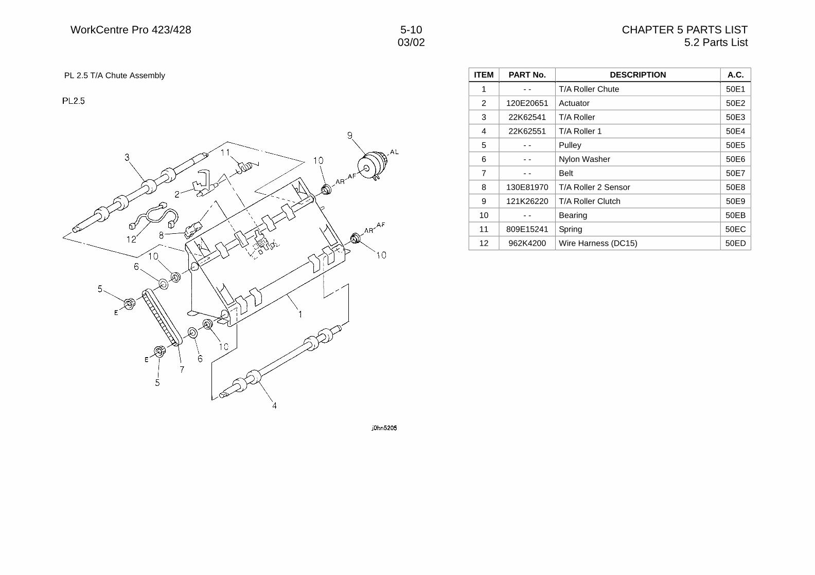
WorkCentre Pro 423/428 5-10 CHAPTER 5 PARTS LIST03/02 5.2 Parts List
PL 2.5 T/A Chute Assembly ITEM PART No. DESCRIPTION A.C.
1 - - T/A Roller Chute 50E1
2 120E20651 Actuator 50E2
3 22K62541 T/A Roller 50E3
4 22K62551 T/A Roller 1 50E4
5 - - Pulley 50E5
6 - - Nylon Washer 50E6
7 - - Belt 50E7
8 130E81970 T/A Roller 2 Sensor 50E8
9 121K26220 T/A Roller Clutch 50E9
10 - - Bearing 50EB
11 809E15241 Spring 50EC
12 962K4200 Wire Harness (DC15) 50ED
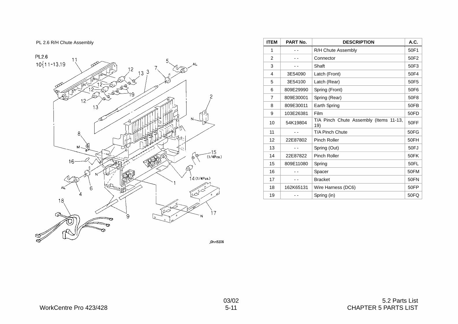
03/02 5.2 Parts ListWorkCentre Pro 423/428 5-11 CHAPTER 5 PARTS LIST
PL 2.6 R/H Chute Assembly ITEM PART No. DESCRIPTION A.C.
1 - - R/H Chute Assembly 50F1
2 - - Connector 50F2
3 - - Shaft 50F3
4 3E54090 Latch (Front) 50F4
5 3E54100 Latch (Rear) 50F5
6 809E29990 Spring (Front) 50F6
7 809E30001 Spring (Rear) 50F8
8 809E30011 Earth Spring 50FB
9 103E26381 Film 50FD
10 54K19804 T/A Pinch Chute Assembly (Items 11-13,19)
50FF
11 - - T/A Pinch Chute 50FG
12 22E87802 Pinch Roller 50FH
13 - - Spring (Out) 50FJ
14 22E87822 Pinch Roller 50FK
15 809E11080 Spring 50FL
16 - - Spacer 50FM
17 - - Bracket 50FN
18 162K65131 Wire Harness (DC6) 50FP
19 - - Spring (in) 50FQ
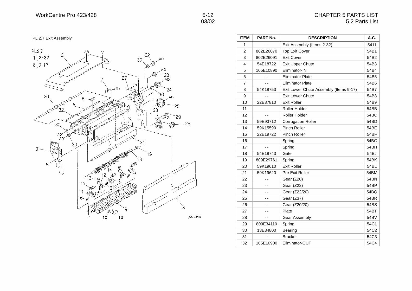
WorkCentre Pro 423/428 5-12 CHAPTER 5 PARTS LIST03/02 5.2 Parts List
PL 2.7 Exit Assembly ITEM PART No. DESCRIPTION A.C.
1 - - Exit Assembly (Items 2-32) 5411
2 802E26070 Top Exit Cover 54B1
3 802E26091 Exit Cover 54B2
4 54E18722 Exit Upper Chute 54B3
5 105E10890 Eliminator-IN 54B4
6 - - Eliminator Plate 54B5
7 - - Eliminator Plate 54B6
8 54K18753 Exit Lower Chute Assembly (Items 9-17) 54B7
9 - - Exit Lower Chute 54B8
10 22E87810 Exit Roller 54B9
11 - - Roller Holder 54BB
12 - - Roller Holder 54BC
13 59E93712 Corrugation Roller 54BD
14 59K15590 Pinch Roller 54BE
15 22E19722 Pinch Roller 54BF
16 - - Spring 54BG
17 - - Spring 54BH
18 54E18743 Gate 54BJ
19 809E29761 Spring 54BK
20 59K19610 Exit Roller 54BL
21 59K19620 Pre Exit Roller 54BM
22 - - Gear (Z20) 54BN
23 - - Gear (Z22) 54BP
24 - - Gear (Z22/20) 54BQ
25 - - Gear (Z37) 54BR
26 - - Gear (Z20/20) 54BS
27 - - Plate 54BT
28 - - Gear Assembly 54BV
29 809E34110 Spring 54C1
30 13E84800 Bearing 54C2
31 - - Bracket 54C3
32 105E10900 Eliminator-OUT 54C4
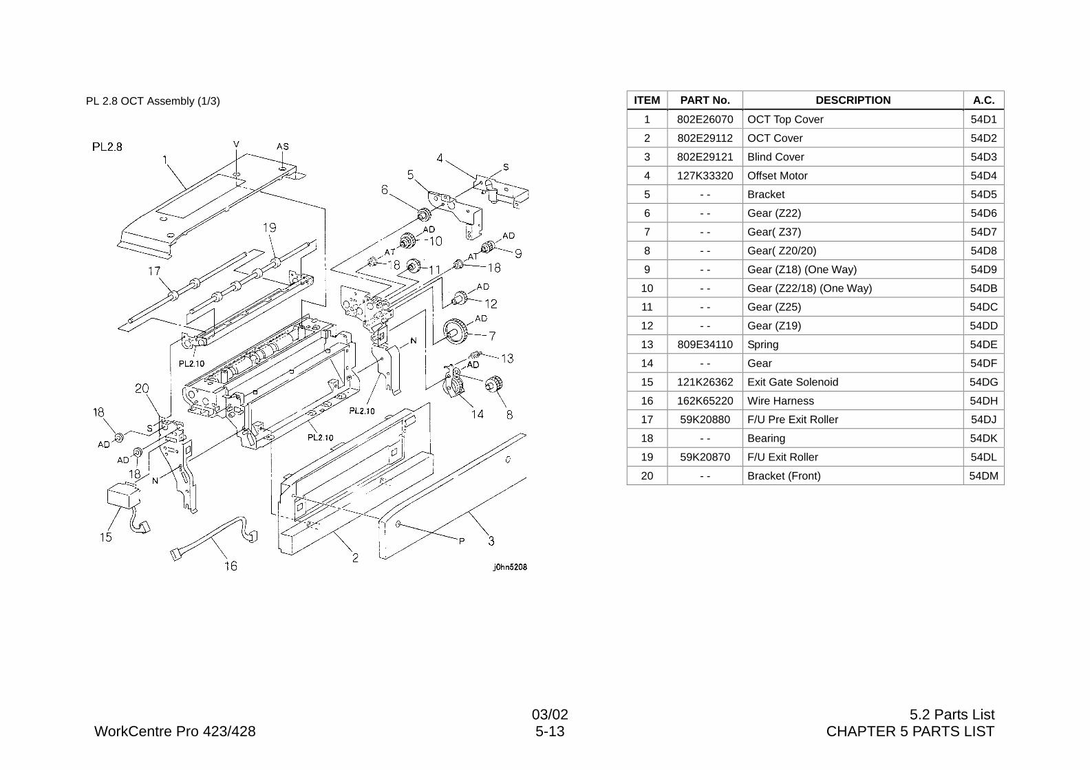
03/02 5.2 Parts ListWorkCentre Pro 423/428 5-13 CHAPTER 5 PARTS LIST
PL 2.8 OCT Assembly (1/3) ITEM PART No. DESCRIPTION A.C.
1 802E26070 OCT Top Cover 54D1
2 802E29112 OCT Cover 54D2
3 802E29121 Blind Cover 54D3
4 127K33320 Offset Motor 54D4
5 - - Bracket 54D5
6 - - Gear (Z22) 54D6
7 - - Gear( Z37) 54D7
8 - - Gear( Z20/20) 54D8
9 - - Gear (Z18) (One Way) 54D9
10 - - Gear (Z22/18) (One Way) 54DB
11 - - Gear (Z25) 54DC
12 - - Gear (Z19) 54DD
13 809E34110 Spring 54DE
14 - - Gear 54DF
15 121K26362 Exit Gate Solenoid 54DG
16 162K65220 Wire Harness 54DH
17 59K20880 F/U Pre Exit Roller 54DJ
18 - - Bearing 54DK
19 59K20870 F/U Exit Roller 54DL
20 - - Bracket (Front) 54DM
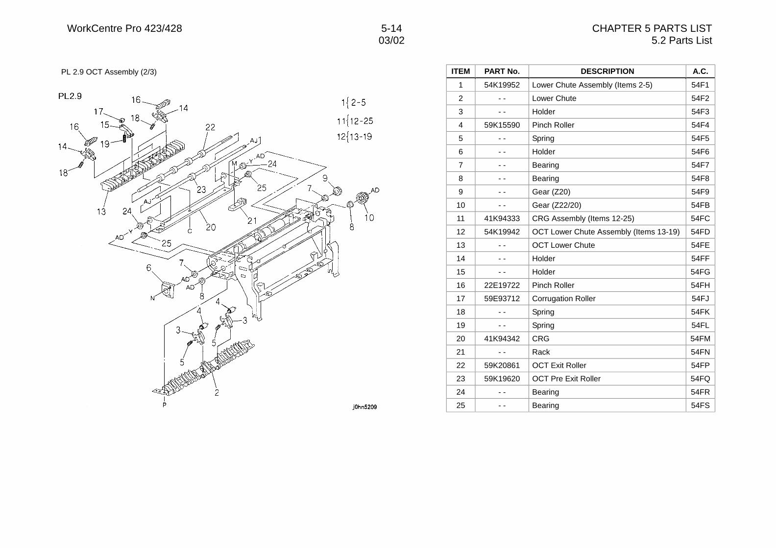
WorkCentre Pro 423/428 5-14 CHAPTER 5 PARTS LIST03/02 5.2 Parts List
PL 2.9 OCT Assembly (2/3) ITEM PART No. DESCRIPTION A.C.
1 54K19952 Lower Chute Assembly (Items 2-5) 54F1
2 - - Lower Chute 54F2
3 - - Holder 54F3
4 59K15590 Pinch Roller 54F4
5 - - Spring 54F5
6 - - Holder 54F6
7 - - Bearing 54F7
8 - - Bearing 54F8
9 - - Gear (Z20) 54F9
10 - - Gear (Z22/20) 54FB
11 41K94333 CRG Assembly (Items 12-25) 54FC
12 54K19942 OCT Lower Chute Assembly (Items 13-19) 54FD
13 - - OCT Lower Chute 54FE
14 - - Holder 54FF
15 - - Holder 54FG
16 22E19722 Pinch Roller 54FH
17 59E93712 Corrugation Roller 54FJ
18 - - Spring 54FK
19 - - Spring 54FL
20 41K94342 CRG 54FM
21 - - Rack 54FN
22 59K20861 OCT Exit Roller 54FP
23 59K19620 OCT Pre Exit Roller 54FQ
24 - - Bearing 54FR
25 - - Bearing 54FS
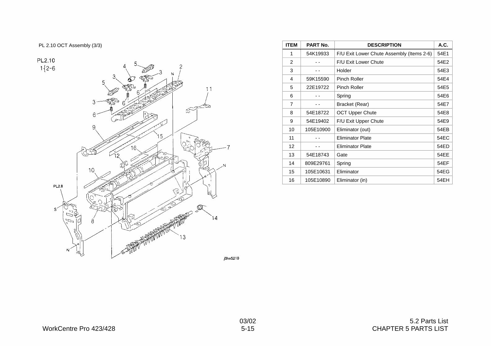
03/02 5.2 Parts ListWorkCentre Pro 423/428 5-15 CHAPTER 5 PARTS LIST
PL 2.10 OCT Assembly (3/3) ITEM PART No. DESCRIPTION A.C.
1 54K19933 F/U Exit Lower Chute Assembly (Items 2-6) 54E1
2 - - F/U Exit Lower Chute 54E2
3 - - Holder 54E3
4 59K15590 Pinch Roller 54E4
5 22E19722 Pinch Roller 54E5
6 - - Spring 54E6
7 - - Bracket (Rear) 54E7
8 54E18722 OCT Upper Chute 54E8
9 54E19402 F/U Exit Upper Chute 54E9
10 105E10900 Eliminator (out) 54EB
11 - - Eliminator Plate 54EC
12 - - Eliminator Plate 54ED
13 54E18743 Gate 54EE
14 809E29761 Spring 54EF
15 105E10631 Eliminator 54EG
16 105E10890 Eliminator (in) 54EH
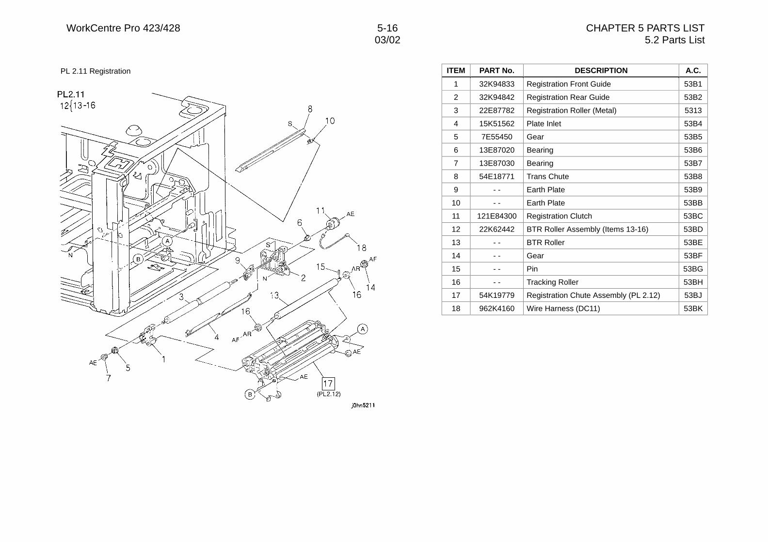
WorkCentre Pro 423/428 5-16 CHAPTER 5 PARTS LIST03/02 5.2 Parts List
PL 2.11 Registration ITEM PART No. DESCRIPTION A.C.
1 32K94833 Registration Front Guide 53B1
2 32K94842 Registration Rear Guide 53B2
3 22E87782 Registration Roller (Metal) 5313
4 15K51562 Plate Inlet 53B4
5 7E55450 Gear 53B5
6 13E87020 Bearing 53B6
7 13E87030 Bearing 53B7
8 54E18771 Trans Chute 53B8
9 - - Earth Plate 53B9
10 - - Earth Plate 53BB
11 121E84300 Registration Clutch 53BC
12 22K62442 BTR Roller Assembly (Items 13-16) 53BD
13 - - BTR Roller 53BE
14 - - Gear 53BF
15 - - Pin 53BG
16 - - Tracking Roller 53BH
17 54K19779 Registration Chute Assembly (PL 2.12) 53BJ
18 962K4160 Wire Harness (DC11) 53BK
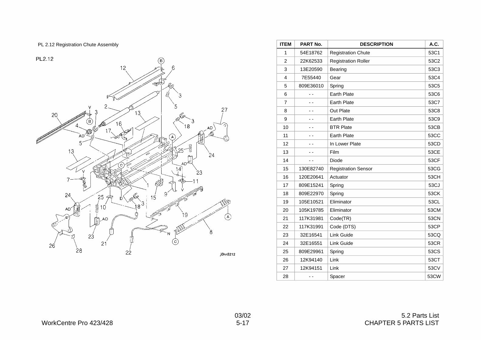
03/02 5.2 Parts ListWorkCentre Pro 423/428 5-17 CHAPTER 5 PARTS LIST
PL 2.12 Registration Chute Assembly ITEM PART No. DESCRIPTION A.C.
1 54E18762 Registration Chute 53C1
2 22K62533 Registration Roller 53C2
3 13E20590 Bearing 53C3
4 7E55440 Gear 53C4
5 809E36010 Spring 53C5
6 - - Earth Plate 53C6
7 - - Earth Plate 53C7
8 - - Out Plate 53C8
9 - - Earth Plate 53C9
10 - - BTR Plate 53CB
11 - - Earth Plate 53CC
12 - - In Lower Plate 53CD
13 - - Film 53CE
14 - - Diode 53CF
15 130E82740 Registration Sensor 53CG
16 120E20641 Actuator 53CH
17 809E15241 Spring 53CJ
18 809E22970 Spring 53CK
19 105E10521 Eliminator 53CL
20 105K19785 Eliminator 53CM
21 117K31981 Code(TR) 53CN
22 117K31991 Code (DTS) 53CP
23 32E16541 Link Guide 53CQ
24 32E16551 Link Guide 53CR
25 809E29961 Spring 53CS
26 12K94140 Link 53CT
27 12K94151 Link 53CV
28 - - Spacer 53CW
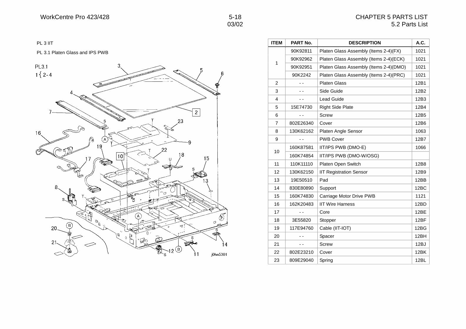
WorkCentre Pro 423/428 5-18 CHAPTER 5 PARTS LIST03/02 5.2 Parts List
PL 3 IIT
PL 3.1 Platen Glass and IPS PWB
ITEM PART No. DESCRIPTION A.C.
90K92811 Platen Glass Assembly (Items 2-4)(FX) 1021
90K92962 Platen Glass Assembly (Items 2-4)(ECK) 1021
90K92951 Platen Glass Assembly (Items 2-4)(DMO) 10211
90K2242 Platen Glass Assembly (Items 2-4)(PRC) 1021
2 - - Platen Glass 12B1
3 - - Side Guide 12B2
4 - - Lead Guide 12B3
5 15E74730 Right Side Plate 12B4
6 - - Screw 12B5
7 802E26340 Cover 12B6
8 130K62162 Platen Angle Sensor 1063
9 - - PWB Cover 12B7
160K87581 IIT/IPS PWB (DMO-E) 106610
160K74854 IIT/IPS PWB (DMO-W/OSG)
11 110K11110 Platen Open Switch 12B8
12 130K62150 IIT Registration Sensor 12B9
13 19E50510 Pad 12BB
14 830E80890 Support 12BC
15 160K74830 Carriage Motor Drive PWB 1121
16 162K20483 IIT Wire Harness 12BD
17 - - Core 12BE
18 3E55820 Stopper 12BF
19 117E94760 Cable (IIT-IOT) 12BG
20 - - Spacer 12BH
21 - - Screw 12BJ
22 802E23210 Cover 12BK
23 809E29040 Spring 12BL
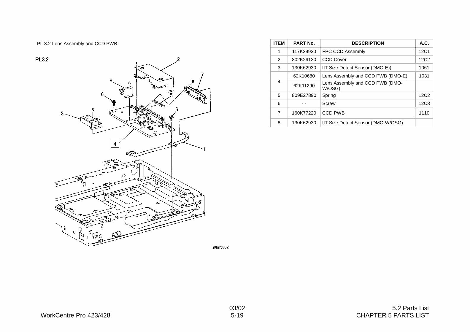
03/02 5.2 Parts ListWorkCentre Pro 423/428 5-19 CHAPTER 5 PARTS LIST
PL 3.2 Lens Assembly and CCD PWB ITEM PART No. DESCRIPTION A.C.
1 117K29920 FPC CCD Assembly 12C1
2 802K29130 CCD Cover 12C2
3 130K62930 IIT Size Detect Sensor (DMO-E)) 1061
62K10680 Lens Assembly and CCD PWB (DMO-E) 10314
62K11290 Lens Assembly and CCD PWB (DMO-W/OSG)
5 809E27890 Spring 12C2
6 - - Screw 12C3
7 160K77220 CCD PWB 1110
8 130K62930 IIT Size Detect Sensor (DMO-W/OSG)
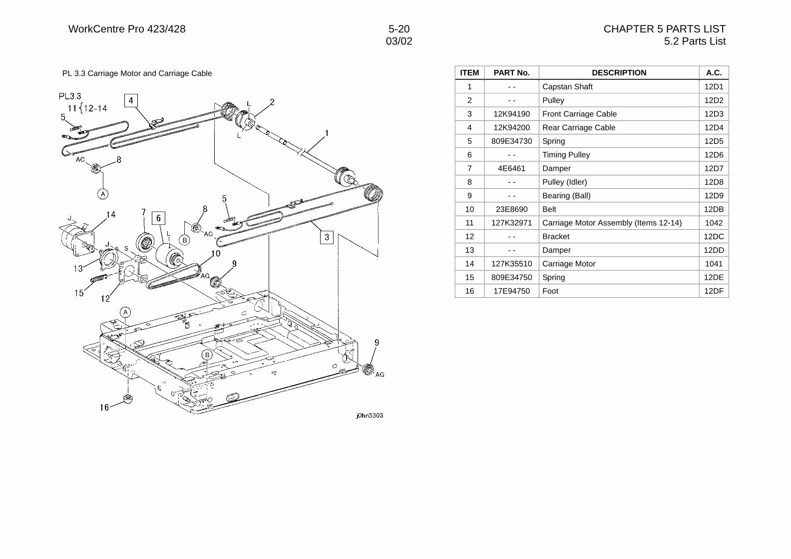
WorkCentre Pro 423/428 5-20 CHAPTER 5 PARTS LIST03/02 5.2 Parts List
PL 3.3 Carriage Motor and Carriage Cable ITEM PART No. DESCRIPTION A.C.
1 - - Capstan Shaft 12D1
2 - - Pulley 12D2
3 12K94190 Front Carriage Cable 12D3
4 12K94200 Rear Carriage Cable 12D4
5 809E34730 Spring 12D5
6 - - Timing Pulley 12D6
7 4E6461 Damper 12D7
8 - - Pulley (Idler) 12D8
9 - - Bearing (Ball) 12D9
10 23E8690 Belt 12DB
11 127K32971 Carriage Motor Assembly (Items 12-14) 1042
12 - - Bracket 12DC
13 - - Damper 12DD
14 127K35510 Carriage Motor 1041
15 809E34750 Spring 12DE
16 17E94750 Foot 12DF
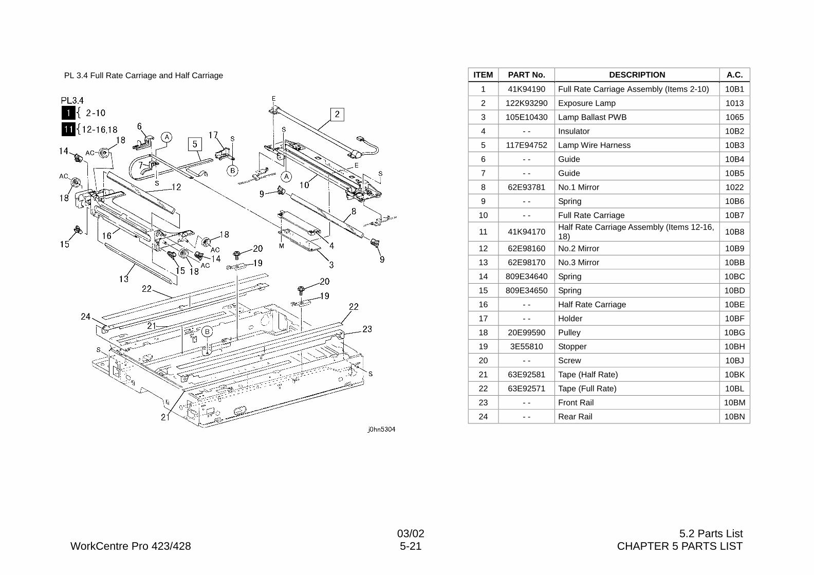
03/02 5.2 Parts ListWorkCentre Pro 423/428 5-21 CHAPTER 5 PARTS LIST
PL 3.4 Full Rate Carriage and Half Carriage ITEM PART No. DESCRIPTION A.C.
1 41K94190 Full Rate Carriage Assembly (Items 2-10) 10B1
2 122K93290 Exposure Lamp 1013
3 105E10430 Lamp Ballast PWB 1065
4 - - Insulator 10B2
5 117E94752 Lamp Wire Harness 10B3
6 - - Guide 10B4
7 - - Guide 10B5
8 62E93781 No.1 Mirror 1022
9 - - Spring 10B6
10 - - Full Rate Carriage 10B7
11 41K94170 Half Rate Carriage Assembly (Items 12-16,18) 10B8
12 62E98160 No.2 Mirror 10B9
13 62E98170 No.3 Mirror 10BB
14 809E34640 Spring 10BC
15 809E34650 Spring 10BD
16 - - Half Rate Carriage 10BE
17 - - Holder 10BF
18 20E99590 Pulley 10BG
19 3E55810 Stopper 10BH
20 - - Screw 10BJ
21 63E92581 Tape (Half Rate) 10BK
22 63E92571 Tape (Full Rate) 10BL
23 - - Front Rail 10BM
24 - - Rear Rail 10BN
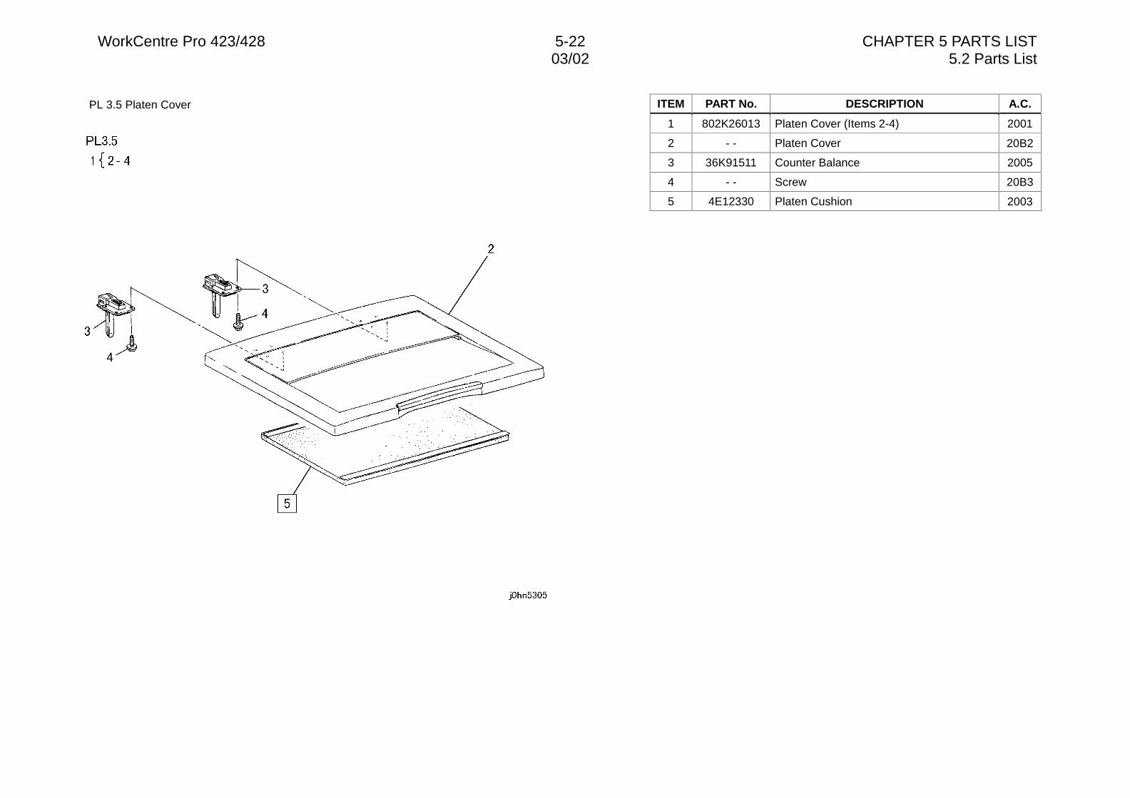
WorkCentre Pro 423/428 5-22 CHAPTER 5 PARTS LIST03/02 5.2 Parts List
PL 3.5 Platen Cover ITEM PART No. DESCRIPTION A.C.
1 802K26013 Platen Cover (Items 2-4) 2001
2 - - Platen Cover 20B2
3 36K91511 Counter Balance 2005
4 - - Screw 20B3
5 4E12330 Platen Cushion 2003
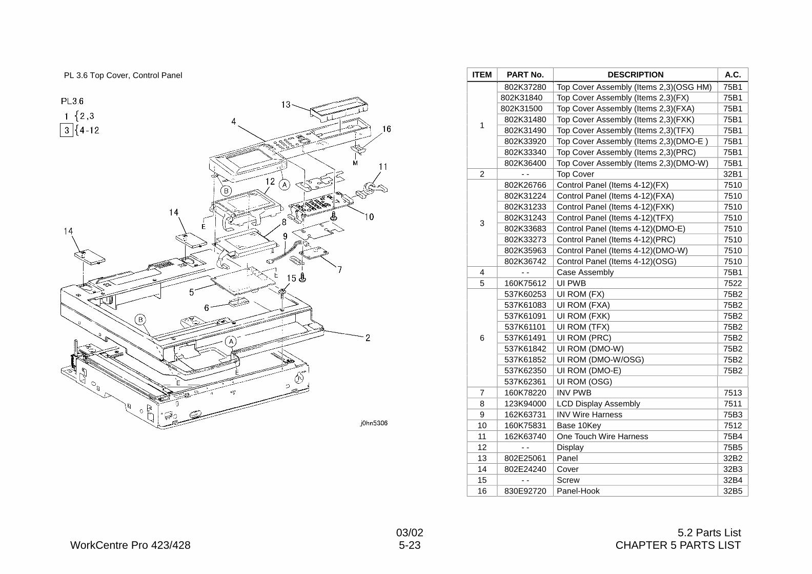
03/02 5.2 Parts ListWorkCentre Pro 423/428 5-23 CHAPTER 5 PARTS LIST
PL 3.6 Top Cover, Control Panel ITEM PART No. DESCRIPTION A.C.
802K37280 Top Cover Assembly (Items 2,3)(OSG HM) 75B1802K31840 Top Cover Assembly (Items 2,3)(FX) 75B1802K31500 Top Cover Assembly (Items 2,3)(FXA) 75B1802K31480 Top Cover Assembly (Items 2,3)(FXK) 75B1802K31490 Top Cover Assembly (Items 2,3)(TFX) 75B1802K33920 Top Cover Assembly (Items 2,3)(DMO-E ) 75B1802K33340 Top Cover Assembly (Items 2,3)(PRC) 75B1
1
802K36400 Top Cover Assembly (Items 2,3)(DMO-W) 75B12 - - Top Cover 32B1
802K26766 Control Panel (Items 4-12)(FX) 7510802K31224 Control Panel (Items 4-12)(FXA) 7510802K31233 Control Panel (Items 4-12)(FXK) 7510802K31243 Control Panel (Items 4-12)(TFX) 7510802K33683 Control Panel (Items 4-12)(DMO-E) 7510802K33273 Control Panel (Items 4-12)(PRC) 7510802K35963 Control Panel (Items 4-12)(DMO-W) 7510
3
802K36742 Control Panel (Items 4-12)(OSG) 75104 - - Case Assembly 75B15 160K75612 UI PWB 7522
537K60253 UI ROM (FX) 75B2537K61083 UI ROM (FXA) 75B2537K61091 UI ROM (FXK) 75B2537K61101 UI ROM (TFX) 75B2537K61491 UI ROM (PRC) 75B2537K61842 UI ROM (DMO-W) 75B2537K61852 UI ROM (DMO-W/OSG) 75B2537K62350 UI ROM (DMO-E) 75B2
6
537K62361 UI ROM (OSG)7 160K78220 INV PWB 75138 123K94000 LCD Display Assembly 75119 162K63731 INV Wire Harness 75B3
10 160K75831 Base 10Key 751211 162K63740 One Touch Wire Harness 75B412 - - Display 75B513 802E25061 Panel 32B214 802E24240 Cover 32B315 - - Screw 32B416 830E92720 Panel-Hook 32B5
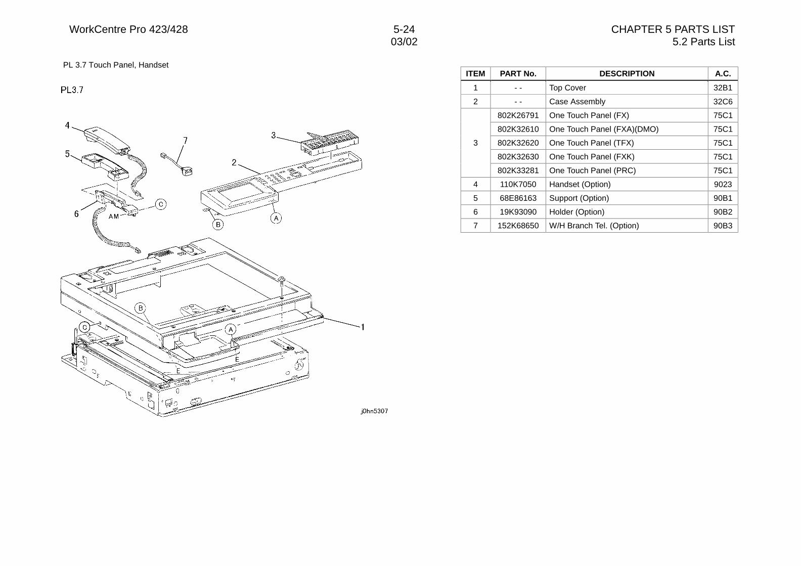
WorkCentre Pro 423/428 5-24 CHAPTER 5 PARTS LIST03/02 5.2 Parts List
PL 3.7 Touch Panel, HandsetITEM PART No. DESCRIPTION A.C.
1 - - Top Cover 32B1
2 - - Case Assembly 32C6
802K26791 One Touch Panel (FX) 75C1
802K32610 One Touch Panel (FXA)(DMO) 75C1
802K32620 One Touch Panel (TFX) 75C1
802K32630 One Touch Panel (FXK) 75C1
3
802K33281 One Touch Panel (PRC) 75C1
4 110K7050 Handset (Option) 9023
5 68E86163 Support (Option) 90B1
6 19K93090 Holder (Option) 90B2
7 152K68650 W/H Branch Tel. (Option) 90B3
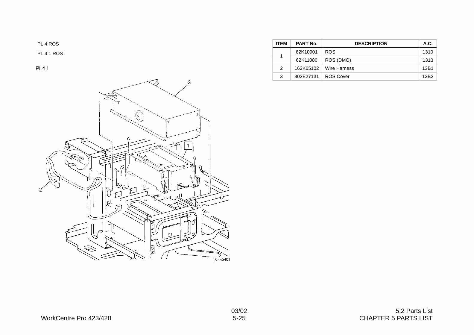
03/02 5.2 Parts ListWorkCentre Pro 423/428 5-25 CHAPTER 5 PARTS LIST
PL 4 ROS
PL 4.1 ROS
ITEM PART No. DESCRIPTION A.C.
62K10901 ROS 13101
62K11080 ROS (DMO) 1310
2 162K65102 Wire Harness 13B1
3 802E27131 ROS Cover 13B2
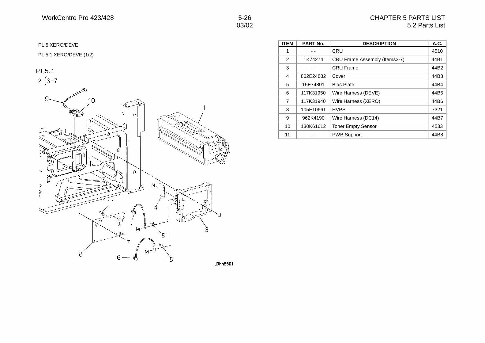
WorkCentre Pro 423/428 5-26 CHAPTER 5 PARTS LIST03/02 5.2 Parts List
PL 5 XERO/DEVE
PL 5.1 XERO/DEVE (1/2)
ITEM PART No. DESCRIPTION A.C.
1 - - CRU 4510
2 1K74274 CRU Frame Assembly (Items3-7) 44B1
3 - - CRU Frame 44B2
4 802E24882 Cover 44B3
5 15E74801 Bias Plate 44B4
6 117K31950 Wire Harness (DEVE) 44B5
7 117K31940 Wire Harness (XERO) 44B6
8 105E10661 HVPS 7321
9 962K4190 Wire Harness (DC14) 44B7
10 130K61612 Toner Empty Sensor 4533
11 - - PWB Support 44B8
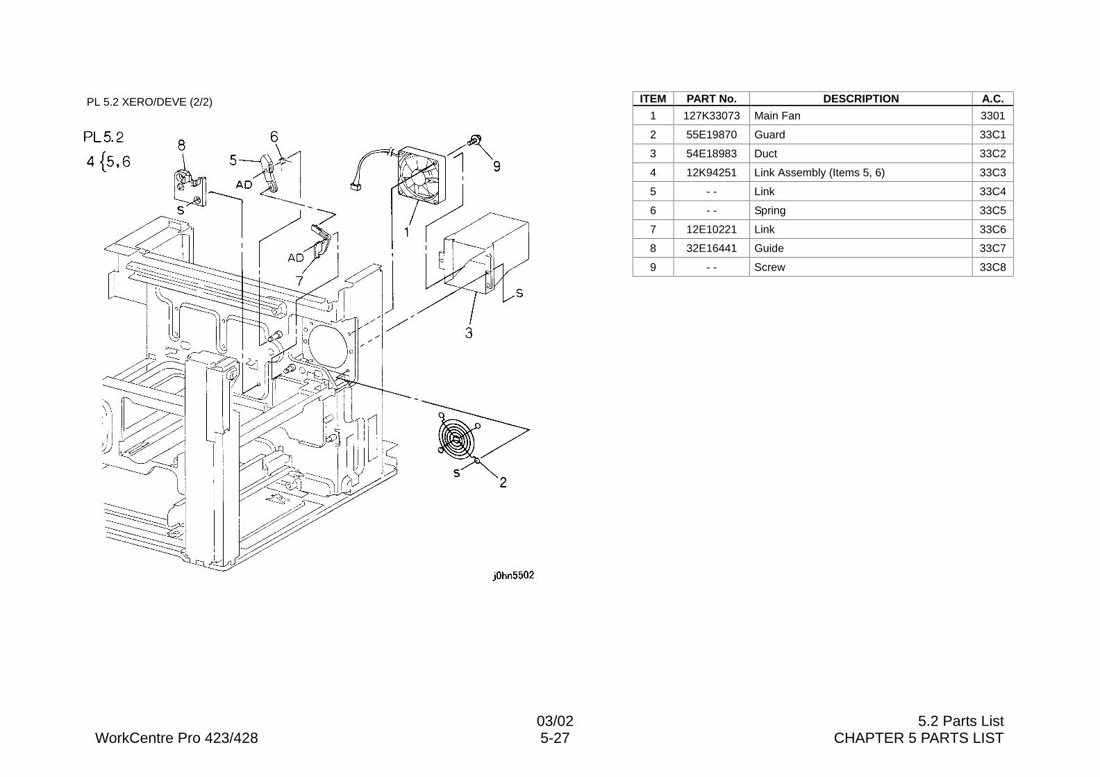
03/02 5.2 Parts ListWorkCentre Pro 423/428 5-27 CHAPTER 5 PARTS LIST
PL 5.2 XERO/DEVE (2/2) ITEM PART No. DESCRIPTION A.C.
1 127K33073 Main Fan 3301
2 55E19870 Guard 33C1
3 54E18983 Duct 33C2
4 12K94251 Link Assembly (Items 5, 6) 33C3
5 - - Link 33C4
6 - - Spring 33C5
7 12E10221 Link 33C6
8 32E16441 Guide 33C7
9 - - Screw 33C8
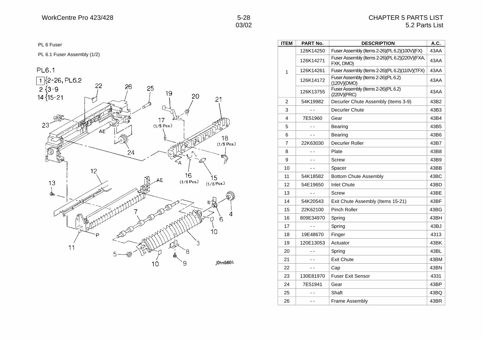
WorkCentre Pro 423/428 5-28 CHAPTER 5 PARTS LIST03/02 5.2 Parts List
PL 6 Fuser
PL 6.1 Fuser Assembly (1/2)
ITEM PART No. DESCRIPTION A.C.
126K14250 Fuser Assembly (Items 2-26)(PL 6.2)(100V)(FX) 43AA
126K14271 Fuser Assembly (Items 2-26)(PL 6.2)(220V)(FXA,FXK, DMO)
43AA
126K14261 Fuser Assembly (Items 2-26)(PL 6.2)(110V)(TFX) 43AA
126K14172 Fuser Assembly (Items 2-26)(PL 6.2)(120V)(DMO)
43AA
1
126K13755 Fuser Assembly (Items 2-26)(PL 6.2)(220V)(PRC)
43AA
2 54K19982 Decurler Chute Assembly (Items 3-9) 43B2
3 - - Decurler Chute 43B3
4 7E51960 Gear 43B4
5 - - Bearing 43B5
6 - - Bearing 43B6
7 22K63030 Decurler Roller 43B7
8 - - Plate 43B8
9 - - Screw 43B9
10 - - Spacer 43BB
11 54K18582 Bottom Chute Assembly 43BC
12 54E19650 Inlet Chute 43BD
13 - - Screw 43BE
14 54K20543 Exit Chute Assembly (Items 15-21) 43BF
15 22K62100 Pinch Roller 43BG
16 809E34970 Spring 43BH
17 - - Spring 43BJ
18 19E48670 Finger 4313
19 120E13053 Actuator 43BK
20 - - Spring 43BL
21 - - Exit Chute 43BM
22 - - Cap 43BN
23 130E81970 Fuser Exit Sensor 4331
24 7E51941 Gear 43BP
25 - - Shaft 43BQ
26 - - Frame Assembly 43BR
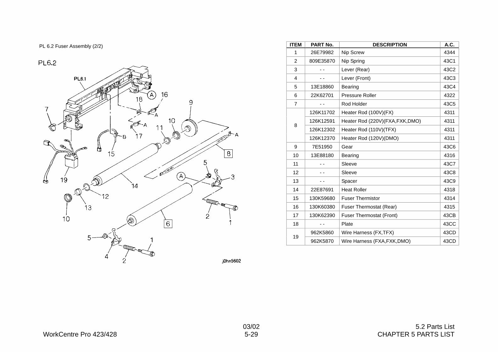
03/02 5.2 Parts ListWorkCentre Pro 423/428 5-29 CHAPTER 5 PARTS LIST
PL 6.2 Fuser Assembly (2/2) ITEM PART No. DESCRIPTION A.C.
1 26E79982 Nip Screw 4344
2 809E35870 Nip Spring 43C1
3 - - Lever (Rear) 43C2
4 - - Lever (Front) 43C3
5 13E18860 Bearing 43C4
6 22K62701 Pressure Roller 4322
7 - - Rod Holder 43C5
126K11702 Heater Rod (100V)(FX) 4311
126K12591 Heater Rod (220V)(FXA,FXK,DMO) 4311
126K12302 Heater Rod (110V)(TFX) 43118
126K12370 Heater Rod (120V)(DMO) 4311
9 7E51950 Gear 43C6
10 13E88180 Bearing 4316
11 - - Sleeve 43C7
12 - - Sleeve 43C8
13 - - Spacer 43C9
14 22E87691 Heat Roller 4318
15 130K59680 Fuser Thermistor 4314
16 130K60380 Fuser Thermostat (Rear) 4315
17 130K62390 Fuser Thermostat (Front) 43CB
18 - - Plate 43CC
962K5860 Wire Harness (FX,TFX) 43CD19
962K5870 Wire Harness (FXA,FXK,DMO) 43CD
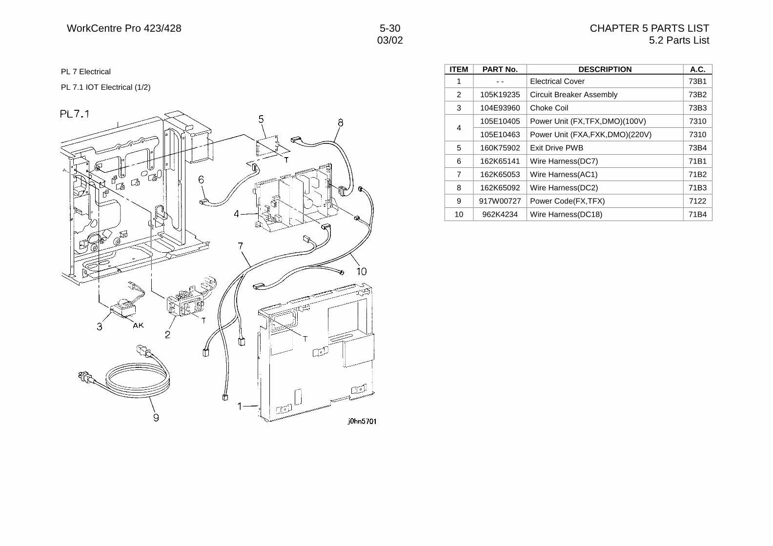
WorkCentre Pro 423/428 5-30 CHAPTER 5 PARTS LIST03/02 5.2 Parts List
PL 7 Electrical
PL 7.1 IOT Electrical (1/2)
ITEM PART No. DESCRIPTION A.C.
1 - - Electrical Cover 73B1
2 105K19235 Circuit Breaker Assembly 73B2
3 104E93960 Choke Coil 73B3
105E10405 Power Unit (FX,TFX,DMO)(100V) 73104
105E10463 Power Unit (FXA,FXK,DMO)(220V) 7310
5 160K75902 Exit Drive PWB 73B4
6 162K65141 Wire Harness(DC7) 71B1
7 162K65053 Wire Harness(AC1) 71B2
8 162K65092 Wire Harness(DC2) 71B3
9 917W00727 Power Code(FX,TFX) 7122
10 962K4234 Wire Harness(DC18) 71B4
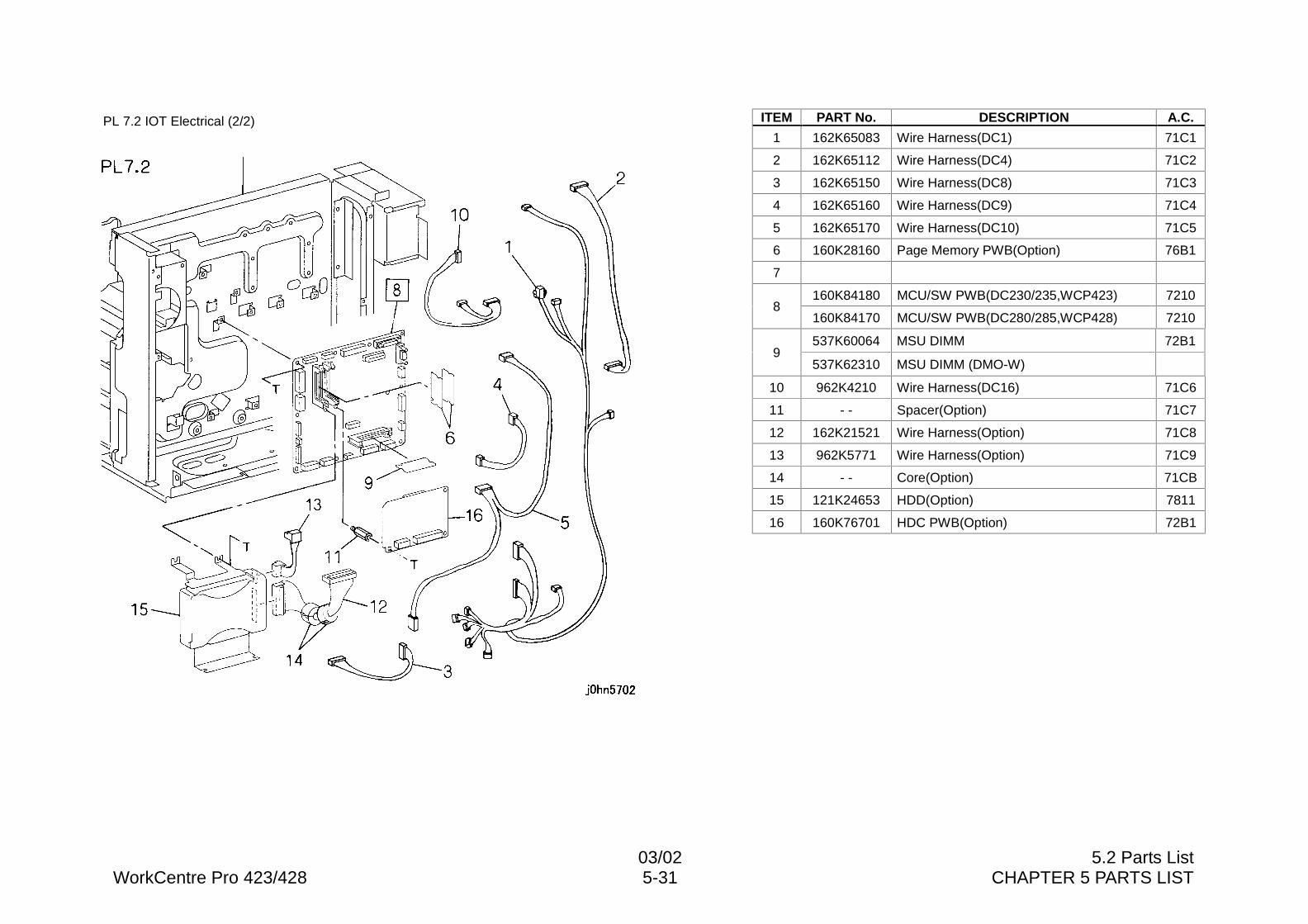
03/02 5.2 Parts ListWorkCentre Pro 423/428 5-31 CHAPTER 5 PARTS LIST
PL 7.2 IOT Electrical (2/2) ITEM PART No. DESCRIPTION A.C.
1 162K65083 Wire Harness(DC1) 71C1
2 162K65112 Wire Harness(DC4) 71C2
3 162K65150 Wire Harness(DC8) 71C3
4 162K65160 Wire Harness(DC9) 71C4
5 162K65170 Wire Harness(DC10) 71C5
6 160K28160 Page Memory PWB(Option) 76B1
7
160K84180 MCU/SW PWB(DC230/235,WCP423) 72108
160K84170 MCU/SW PWB(DC280/285,WCP428) 7210
537K60064 MSU DIMM 72B19
537K62310 MSU DIMM (DMO-W)
10 962K4210 Wire Harness(DC16) 71C6
11 - - Spacer(Option) 71C7
12 162K21521 Wire Harness(Option) 71C8
13 962K5771 Wire Harness(Option) 71C9
14 - - Core(Option) 71CB
15 121K24653 HDD(Option) 7811
16 160K76701 HDC PWB(Option) 72B1
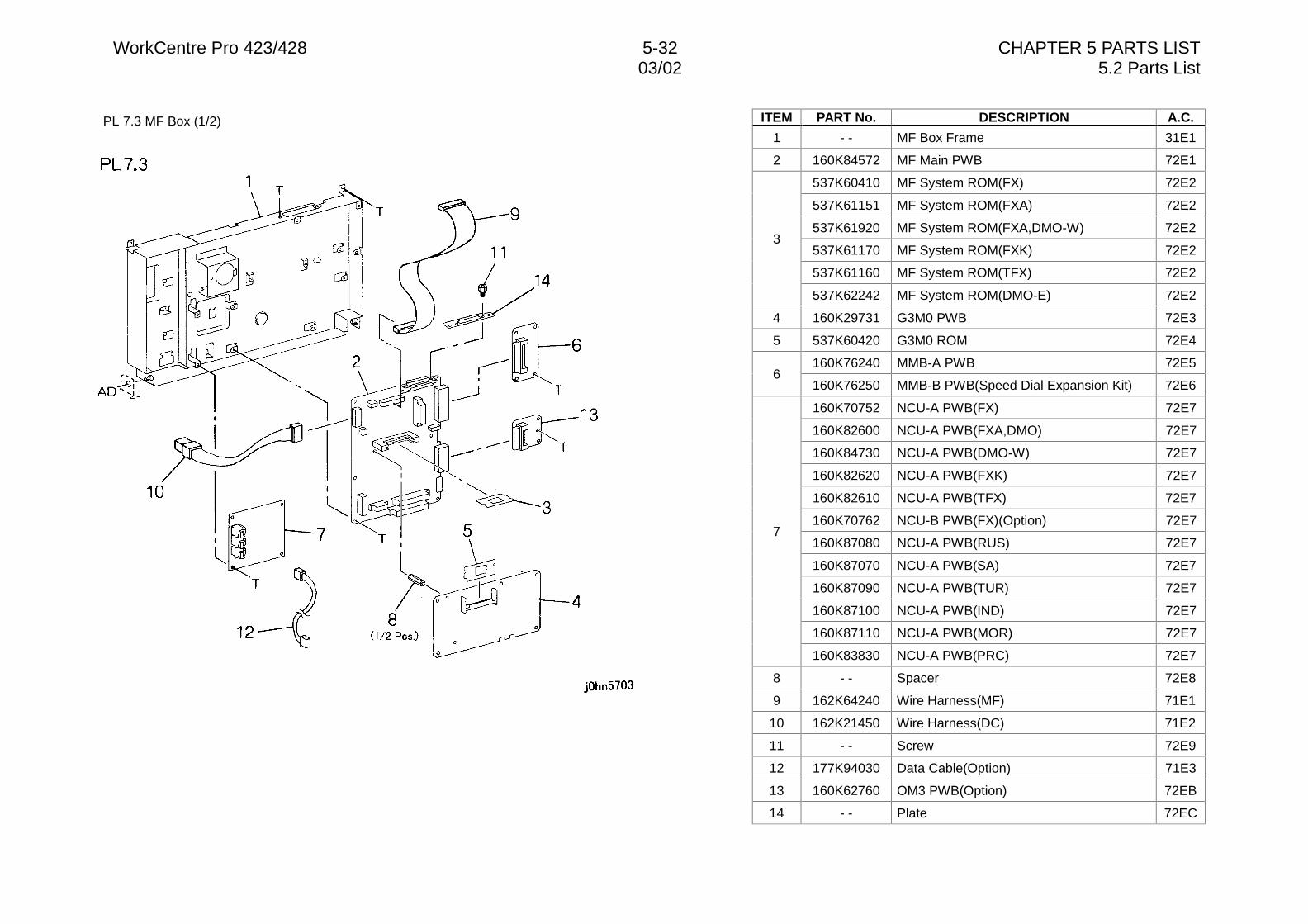
WorkCentre Pro 423/428 5-32 CHAPTER 5 PARTS LIST03/02 5.2 Parts List
PL 7.3 MF Box (1/2) ITEM PART No. DESCRIPTION A.C.
1 - - MF Box Frame 31E1
2 160K84572 MF Main PWB 72E1
537K60410 MF System ROM(FX) 72E2
537K61151 MF System ROM(FXA) 72E2
537K61920 MF System ROM(FXA,DMO-W) 72E2
537K61170 MF System ROM(FXK) 72E2
537K61160 MF System ROM(TFX) 72E2
3
537K62242 MF System ROM(DMO-E) 72E2
4 160K29731 G3M0 PWB 72E3
5 537K60420 G3M0 ROM 72E4
160K76240 MMB-A PWB 72E56
160K76250 MMB-B PWB(Speed Dial Expansion Kit) 72E6
160K70752 NCU-A PWB(FX) 72E7
160K82600 NCU-A PWB(FXA,DMO) 72E7
160K84730 NCU-A PWB(DMO-W) 72E7
160K82620 NCU-A PWB(FXK) 72E7
160K82610 NCU-A PWB(TFX) 72E7
160K70762 NCU-B PWB(FX)(Option) 72E7
160K87080 NCU-A PWB(RUS) 72E7
160K87070 NCU-A PWB(SA) 72E7
160K87090 NCU-A PWB(TUR) 72E7
160K87100 NCU-A PWB(IND) 72E7
160K87110 NCU-A PWB(MOR) 72E7
7
160K83830 NCU-A PWB(PRC) 72E7
8 - - Spacer 72E8
9 162K64240 Wire Harness(MF) 71E1
10 162K21450 Wire Harness(DC) 71E2
11 - - Screw 72E9
12 177K94030 Data Cable(Option) 71E3
13 160K62760 OM3 PWB(Option) 72EB
14 - - Plate 72EC
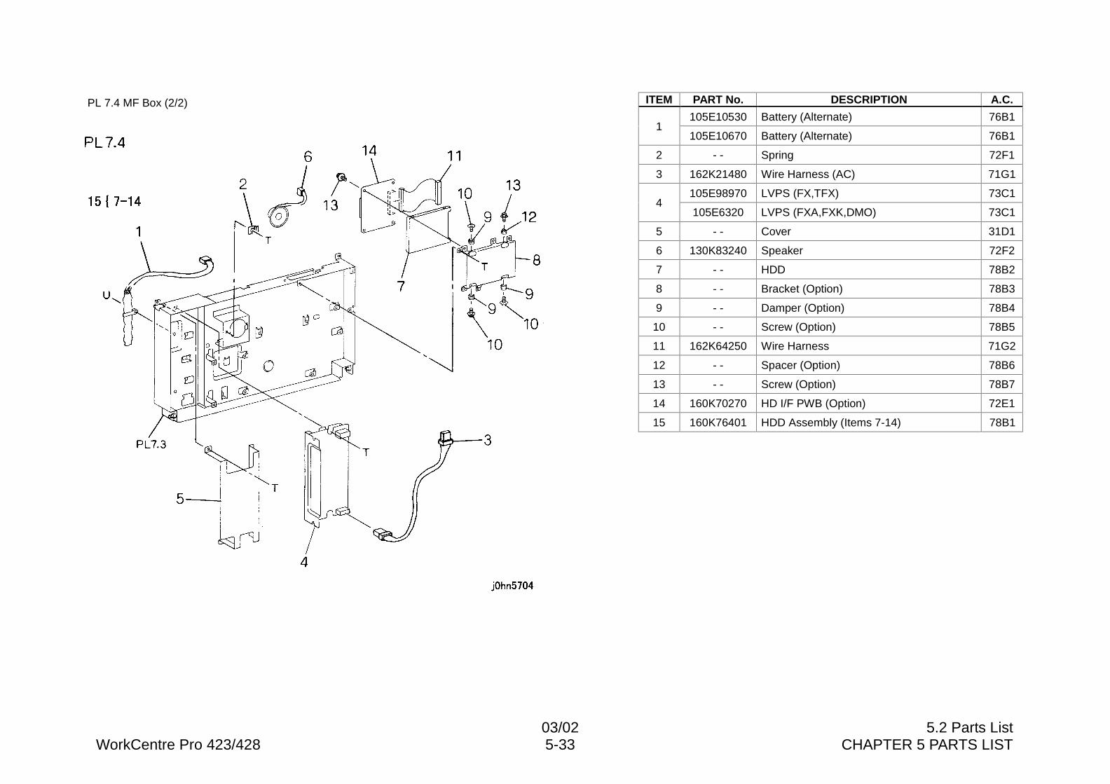
03/02 5.2 Parts ListWorkCentre Pro 423/428 5-33 CHAPTER 5 PARTS LIST
PL 7.4 MF Box (2/2) ITEM PART No. DESCRIPTION A.C.
105E10530 Battery (Alternate) 76B11
105E10670 Battery (Alternate) 76B1
2 - - Spring 72F1
3 162K21480 Wire Harness (AC) 71G1
105E98970 LVPS (FX,TFX) 73C14
105E6320 LVPS (FXA,FXK,DMO) 73C1
5 - - Cover 31D1
6 130K83240 Speaker 72F2
7 - - HDD 78B2
8 - - Bracket (Option) 78B3
9 - - Damper (Option) 78B4
10 - - Screw (Option) 78B5
11 162K64250 Wire Harness 71G2
12 - - Spacer (Option) 78B6
13 - - Screw (Option) 78B7
14 160K70270 HD I/F PWB (Option) 72E1
15 160K76401 HDD Assembly (Items 7-14) 78B1
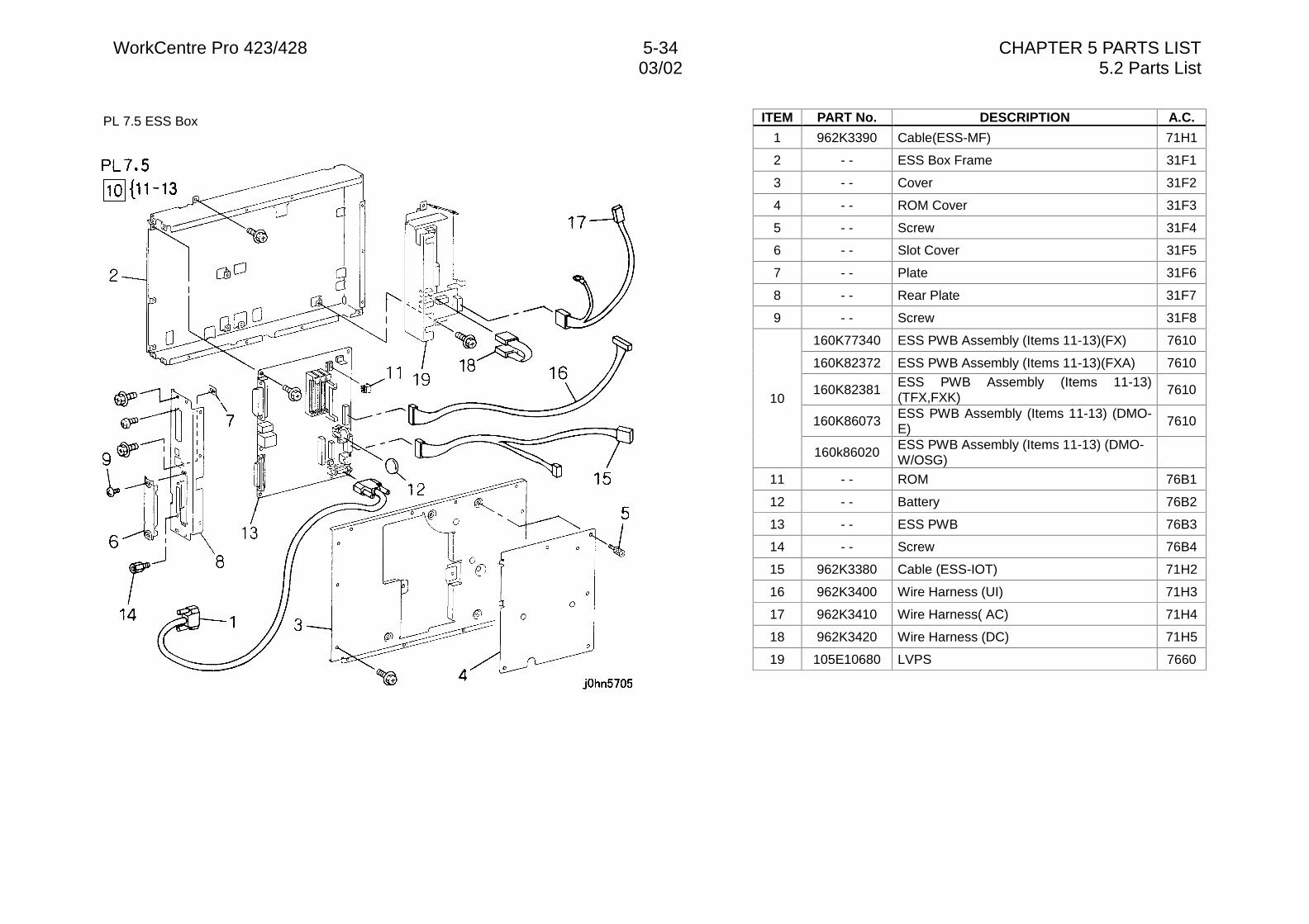
WorkCentre Pro 423/428 5-34 CHAPTER 5 PARTS LIST03/02 5.2 Parts List
PL 7.5 ESS Box ITEM PART No. DESCRIPTION A.C.
1 962K3390 Cable(ESS-MF) 71H1
2 - - ESS Box Frame 31F1
3 - - Cover 31F2
4 - - ROM Cover 31F3
5 - - Screw 31F4
6 - - Slot Cover 31F5
7 - - Plate 31F6
8 - - Rear Plate 31F7
9 - - Screw 31F8
160K77340 ESS PWB Assembly (Items 11-13)(FX) 7610
160K82372 ESS PWB Assembly (Items 11-13)(FXA) 7610
160K82381ESS PWB Assembly (Items 11-13)(TFX,FXK)
7610
160K86073ESS PWB Assembly (Items 11-13) (DMO-E)
7610
10
160k86020ESS PWB Assembly (Items 11-13) (DMO-W/OSG)
11 - - ROM 76B1
12 - - Battery 76B2
13 - - ESS PWB 76B3
14 - - Screw 76B4
15 962K3380 Cable (ESS-IOT) 71H2
16 962K3400 Wire Harness (UI) 71H3
17 962K3410 Wire Harness( AC) 71H4
18 962K3420 Wire Harness (DC) 71H5
19 105E10680 LVPS 7660
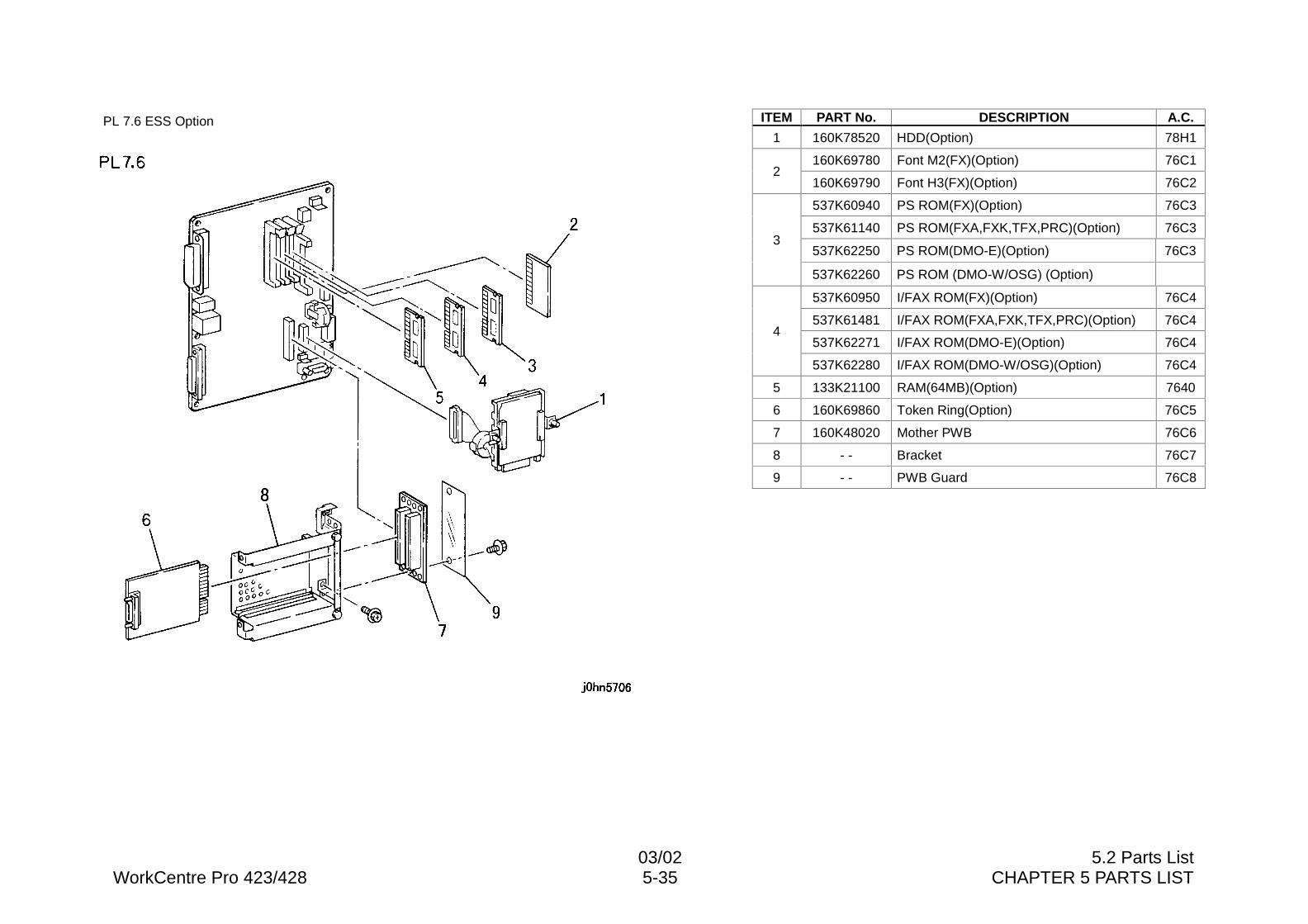
03/02 5.2 Parts ListWorkCentre Pro 423/428 5-35 CHAPTER 5 PARTS LIST
PL 7.6 ESS Option ITEM PART No. DESCRIPTION A.C.
1 160K78520 HDD(Option) 78H1
160K69780 Font M2(FX)(Option) 76C12
160K69790 Font H3(FX)(Option) 76C2
537K60940 PS ROM(FX)(Option) 76C3
537K61140 PS ROM(FXA,FXK,TFX,PRC)(Option) 76C3
537K62250 PS ROM(DMO-E)(Option) 76C33
537K62260 PS ROM (DMO-W/OSG) (Option)
537K60950 I/FAX ROM(FX)(Option) 76C4
537K61481 I/FAX ROM(FXA,FXK,TFX,PRC)(Option) 76C4
537K62271 I/FAX ROM(DMO-E)(Option) 76C44
537K62280 I/FAX ROM(DMO-W/OSG)(Option) 76C4
5 133K21100 RAM(64MB)(Option) 7640
6 160K69860 Token Ring(Option) 76C5
7 160K48020 Mother PWB 76C6
8 - - Bracket 76C7
9 - - PWB Guard 76C8
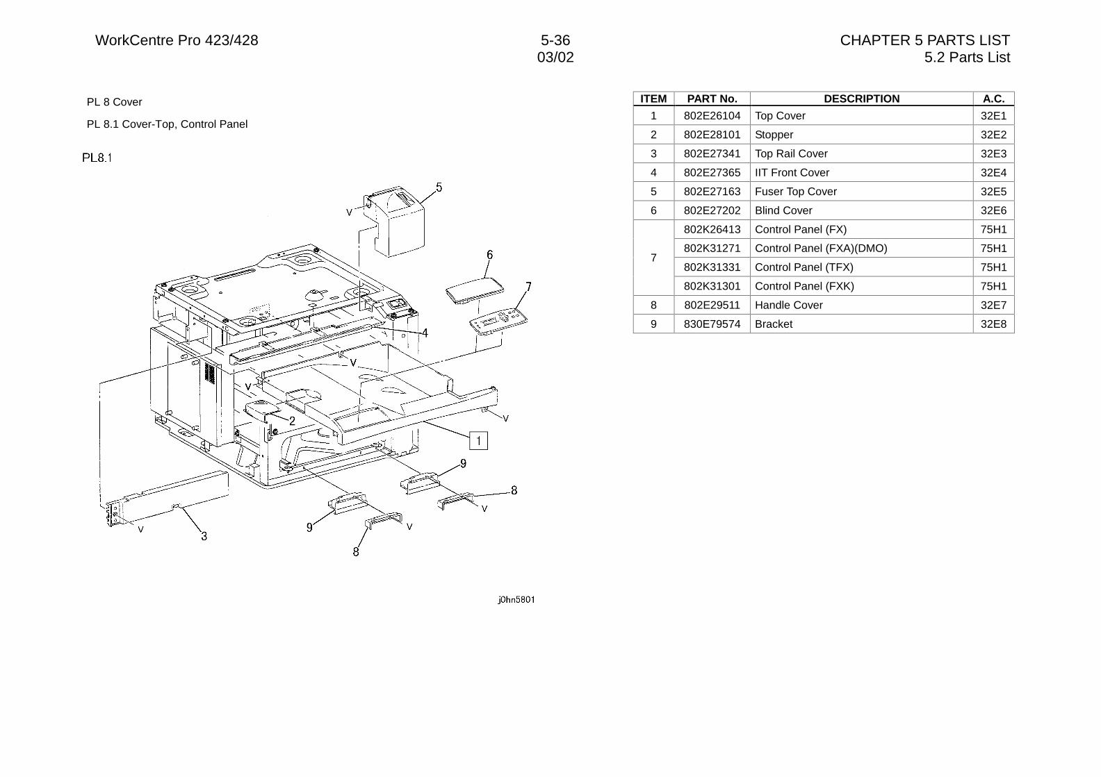
WorkCentre Pro 423/428 5-36 CHAPTER 5 PARTS LIST03/02 5.2 Parts List
PL 8 Cover
PL 8.1 Cover-Top, Control Panel
ITEM PART No. DESCRIPTION A.C.
1 802E26104 Top Cover 32E1
2 802E28101 Stopper 32E2
3 802E27341 Top Rail Cover 32E3
4 802E27365 IIT Front Cover 32E4
5 802E27163 Fuser Top Cover 32E5
6 802E27202 Blind Cover 32E6
802K26413 Control Panel (FX) 75H1
802K31271 Control Panel (FXA)(DMO) 75H1
802K31331 Control Panel (TFX) 75H17
802K31301 Control Panel (FXK) 75H1
8 802E29511 Handle Cover 32E7
9 830E79574 Bracket 32E8
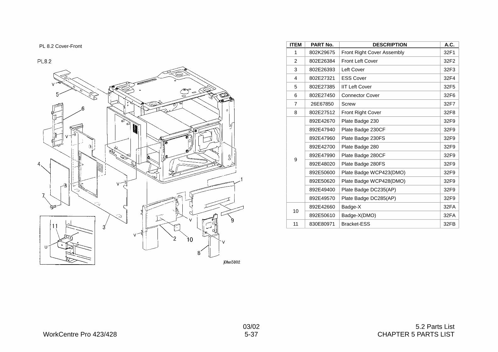
03/02 5.2 Parts ListWorkCentre Pro 423/428 5-37 CHAPTER 5 PARTS LIST
PL 8.2 Cover-Front ITEM PART No. DESCRIPTION A.C.
1 802K29675 Front Right Cover Assembly 32F1
2 802E26384 Front Left Cover 32F2
3 802E26393 Left Cover 32F3
4 802E27321 ESS Cover 32F4
5 802E27385 IIT Left Cover 32F5
6 802E27450 Connector Cover 32F6
7 26E67850 Screw 32F7
8 802E27512 Front Right Cover 32F8
892E42670 Plate Badge 230 32F9
892E47940 Plate Badge 230CF 32F9
892E47960 Plate Badge 230FS 32F9
892E42700 Plate Badge 280 32F9
892E47990 Plate Badge 280CF 32F9
892E48020 Plate Badge 280FS 32F9
892E50600 Plate Badge WCP423(DMO) 32F9
892E50620 Plate Badge WCP428(DMO) 32F9
892E49400 Plate Badge DC235(AP) 32F9
9
892E49570 Plate Badge DC285(AP) 32F9
892E42660 Badge-X 32FA10
892E50610 Badge-X(DMO) 32FA
11 830E80971 Bracket-ESS 32FB
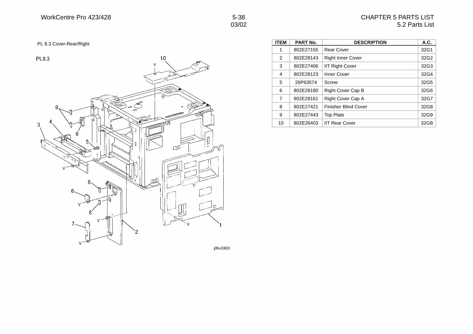
WorkCentre Pro 423/428 5-38 CHAPTER 5 PARTS LIST03/02 5.2 Parts List
PL 8.3 Cover-Rear/Right ITEM PART No. DESCRIPTION A.C.
1 802E27155 Rear Cover 32G1
2 802E28143 Right Inner Cover 32G2
3 802E27406 IIT Right Cover 32G3
4 802E28123 Inner Cover 32G4
5 26P63574 Screw 32G5
6 802E28180 Right Cover Cap B 32G6
7 802E28161 Right Cover Cap A 32G7
8 802E27421 Finisher Blind Cover 32G8
9 802E27443 Top Plate 32G9
10 802E26403 IIT Rear Cover 32GB
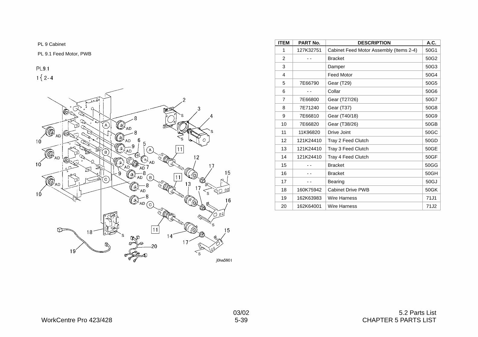
03/02 5.2 Parts ListWorkCentre Pro 423/428 5-39 CHAPTER 5 PARTS LIST
PL 9 Cabinet
PL 9.1 Feed Motor, PWB
ITEM PART No. DESCRIPTION A.C.
1 127K32751 Cabinet Feed Motor Assembly (Items 2-4) 50G1
2 - - Bracket 50G2
3 Damper 50G3
4 Feed Motor 50G4
5 7E66790 Gear (T29) 50G5
6 - - Collar 50G6
7 7E66800 Gear (T27/26) 50G7
8 7E71240 Gear (T37) 50G8
9 7E66810 Gear (T40/18) 50G9
10 7E66820 Gear (T38/26) 50GB
11 11K96820 Drive Joint 50GC
12 121K24410 Tray 2 Feed Clutch 50GD
13 121K24410 Tray 3 Feed Clutch 50GE
14 121K24410 Tray 4 Feed Clutch 50GF
15 - - Bracket 50GG
16 - - Bracket 50GH
17 - - Bearing 50GJ
18 160K75942 Cabinet Drive PWB 50GK
19 162K63983 Wire Harness 71J1
20 162K64001 Wire Harness 71J2
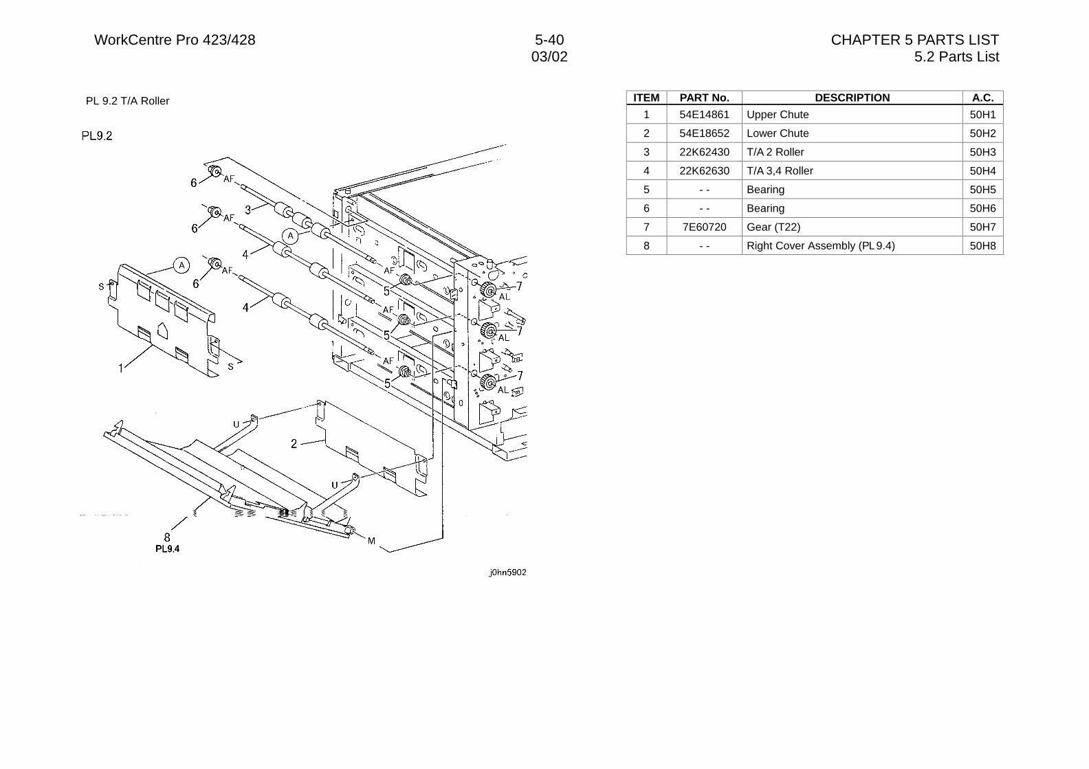
WorkCentre Pro 423/428 5-40 CHAPTER 5 PARTS LIST03/02 5.2 Parts List
PL 9.2 T/A Roller ITEM PART No. DESCRIPTION A.C.
1 54E14861 Upper Chute 50H1
2 54E18652 Lower Chute 50H2
3 22K62430 T/A 2 Roller 50H3
4 22K62630 T/A 3,4 Roller 50H4
5 - - Bearing 50H5
6 - - Bearing 50H6
7 7E60720 Gear (T22) 50H7
8 - - Right Cover Assembly (PL 9.4) 50H8
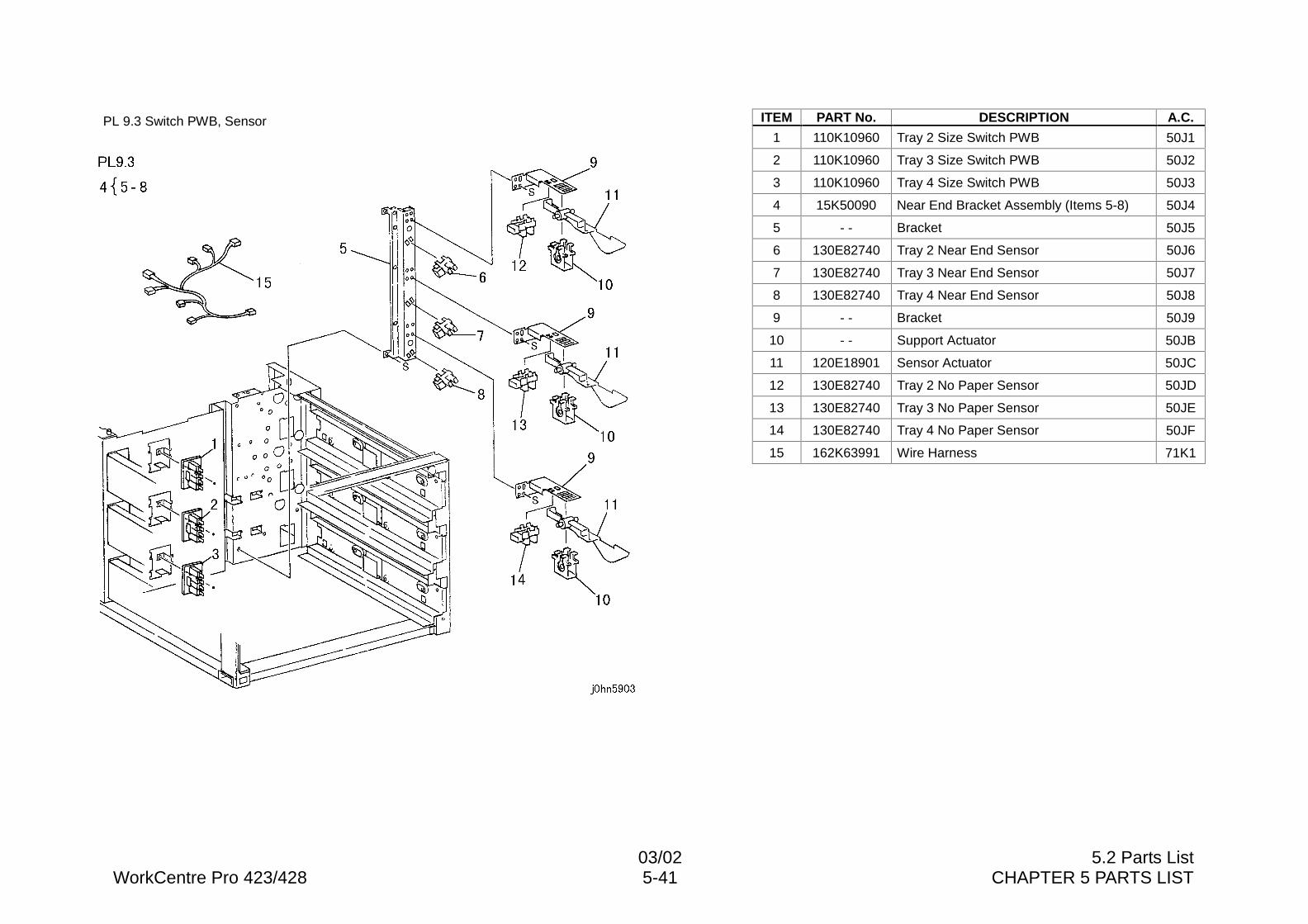
03/02 5.2 Parts ListWorkCentre Pro 423/428 5-41 CHAPTER 5 PARTS LIST
PL 9.3 Switch PWB, Sensor ITEM PART No. DESCRIPTION A.C.
1 110K10960 Tray 2 Size Switch PWB 50J1
2 110K10960 Tray 3 Size Switch PWB 50J2
3 110K10960 Tray 4 Size Switch PWB 50J3
4 15K50090 Near End Bracket Assembly (Items 5-8) 50J4
5 - - Bracket 50J5
6 130E82740 Tray 2 Near End Sensor 50J6
7 130E82740 Tray 3 Near End Sensor 50J7
8 130E82740 Tray 4 Near End Sensor 50J8
9 - - Bracket 50J9
10 - - Support Actuator 50JB
11 120E18901 Sensor Actuator 50JC
12 130E82740 Tray 2 No Paper Sensor 50JD
13 130E82740 Tray 3 No Paper Sensor 50JE
14 130E82740 Tray 4 No Paper Sensor 50JF
15 162K63991 Wire Harness 71K1
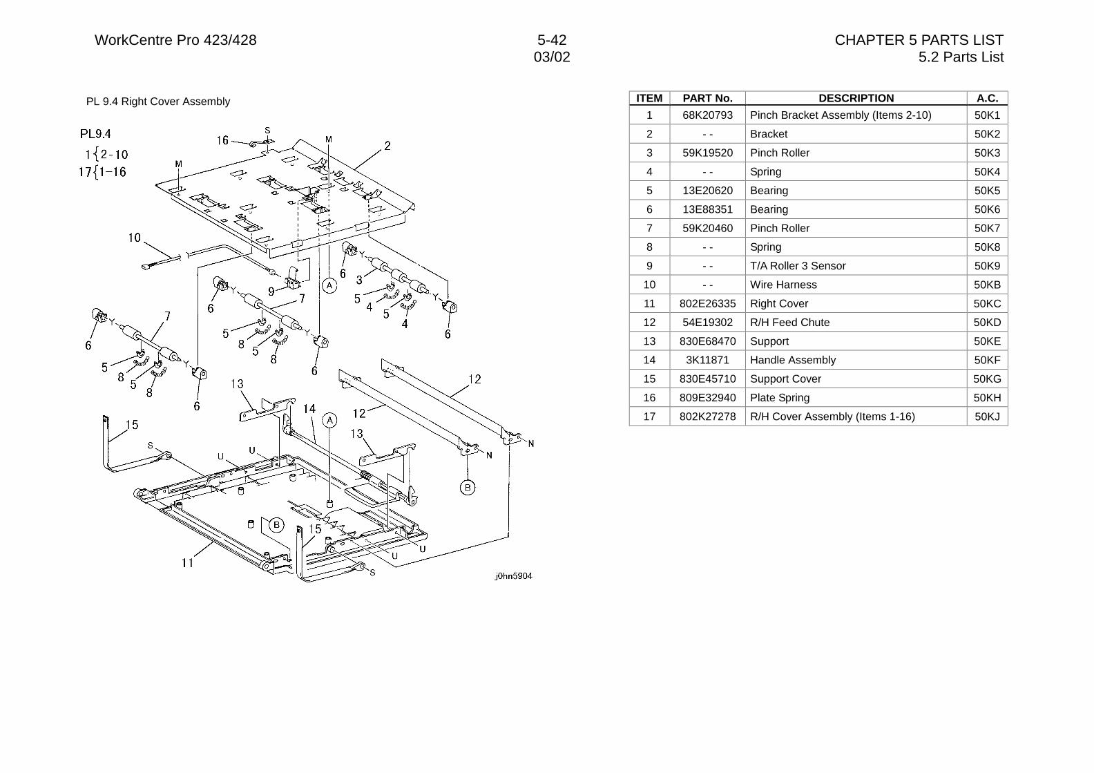
WorkCentre Pro 423/428 5-42 CHAPTER 5 PARTS LIST03/02 5.2 Parts List
PL 9.4 Right Cover Assembly ITEM PART No. DESCRIPTION A.C.
1 68K20793 Pinch Bracket Assembly (Items 2-10) 50K1
2 - - Bracket 50K2
3 59K19520 Pinch Roller 50K3
4 - - Spring 50K4
5 13E20620 Bearing 50K5
6 13E88351 Bearing 50K6
7 59K20460 Pinch Roller 50K7
8 - - Spring 50K8
9 - - T/A Roller 3 Sensor 50K9
10 - - Wire Harness 50KB
11 802E26335 Right Cover 50KC
12 54E19302 R/H Feed Chute 50KD
13 830E68470 Support 50KE
14 3K11871 Handle Assembly 50KF
15 830E45710 Support Cover 50KG
16 809E32940 Plate Spring 50KH
17 802K27278 R/H Cover Assembly (Items 1-16) 50KJ
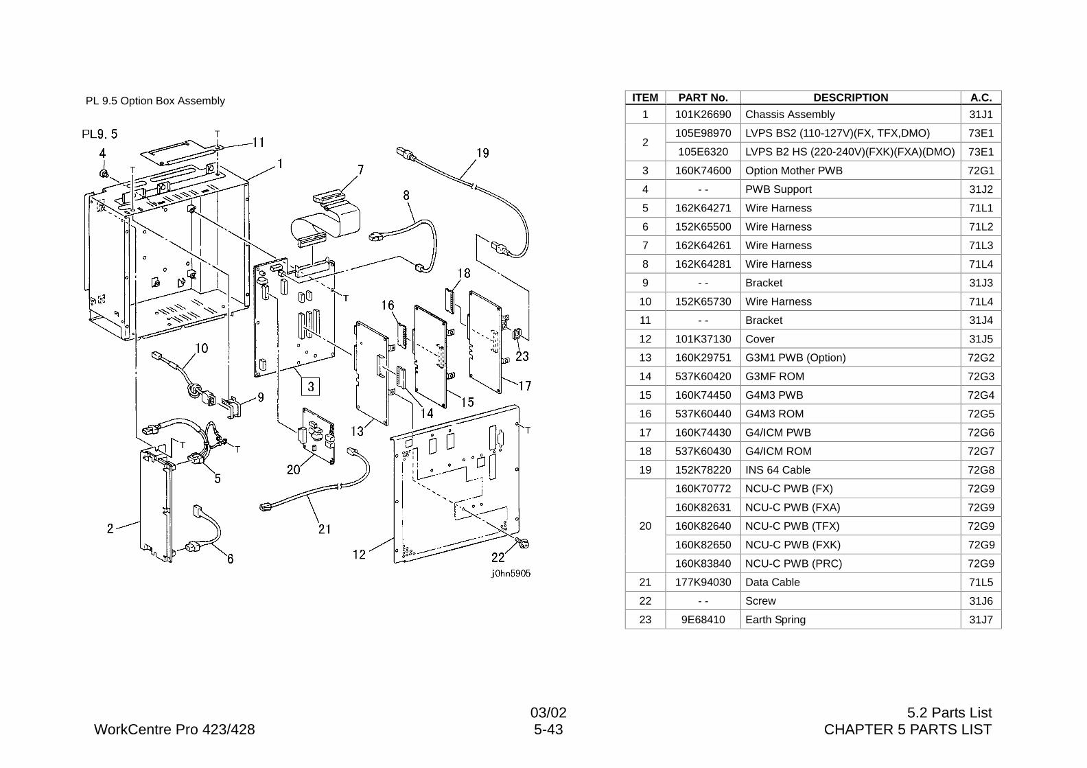
03/02 5.2 Parts ListWorkCentre Pro 423/428 5-43 CHAPTER 5 PARTS LIST
PL 9.5 Option Box Assembly ITEM PART No. DESCRIPTION A.C.
1 101K26690 Chassis Assembly 31J1
105E98970 LVPS BS2 (110-127V)(FX, TFX,DMO) 73E12
105E6320 LVPS B2 HS (220-240V)(FXK)(FXA)(DMO) 73E1
3 160K74600 Option Mother PWB 72G1
4 - - PWB Support 31J2
5 162K64271 Wire Harness 71L1
6 152K65500 Wire Harness 71L2
7 162K64261 Wire Harness 71L3
8 162K64281 Wire Harness 71L4
9 - - Bracket 31J3
10 152K65730 Wire Harness 71L4
11 - - Bracket 31J4
12 101K37130 Cover 31J5
13 160K29751 G3M1 PWB (Option) 72G2
14 537K60420 G3MF ROM 72G3
15 160K74450 G4M3 PWB 72G4
16 537K60440 G4M3 ROM 72G5
17 160K74430 G4/ICM PWB 72G6
18 537K60430 G4/ICM ROM 72G7
19 152K78220 INS 64 Cable 72G8
160K70772 NCU-C PWB (FX) 72G9
160K82631 NCU-C PWB (FXA) 72G9
160K82640 NCU-C PWB (TFX) 72G9
160K82650 NCU-C PWB (FXK) 72G9
20
160K83840 NCU-C PWB (PRC) 72G9
21 177K94030 Data Cable 71L5
22 - - Screw 31J6
23 9E68410 Earth Spring 31J7
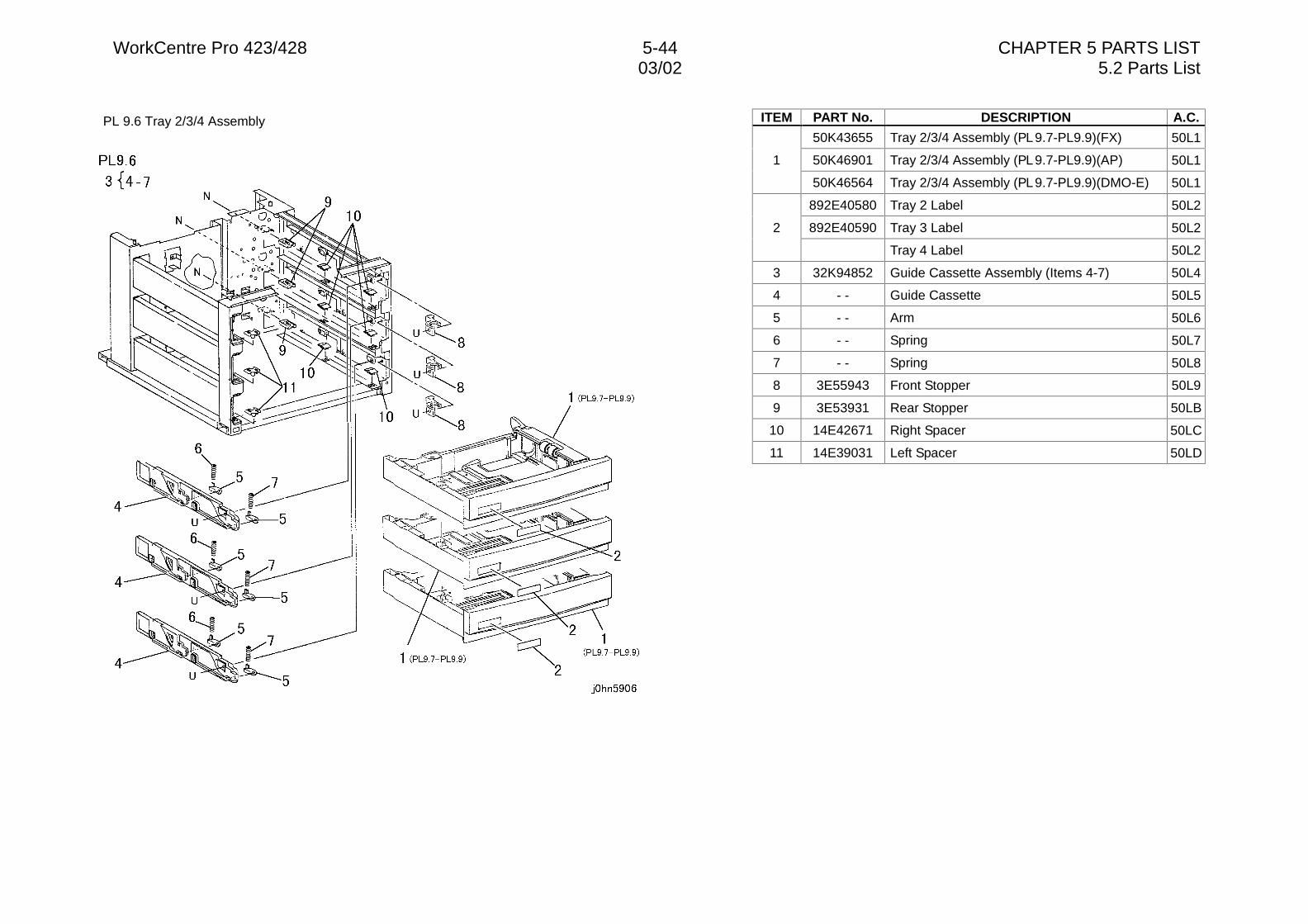
WorkCentre Pro 423/428 5-44 CHAPTER 5 PARTS LIST03/02 5.2 Parts List
PL 9.6 Tray 2/3/4 Assembly ITEM PART No. DESCRIPTION A.C.
50K43655 Tray 2/3/4 Assembly (PL 9.7-PL9.9)(FX) 50L1
50K46901 Tray 2/3/4 Assembly (PL 9.7-PL9.9)(AP) 50L11
50K46564 Tray 2/3/4 Assembly (PL 9.7-PL9.9)(DMO-E) 50L1
892E40580 Tray 2 Label 50L2
892E40590 Tray 3 Label 50L22
Tray 4 Label 50L2
3 32K94852 Guide Cassette Assembly (Items 4-7) 50L4
4 - - Guide Cassette 50L5
5 - - Arm 50L6
6 - - Spring 50L7
7 - - Spring 50L8
8 3E55943 Front Stopper 50L9
9 3E53931 Rear Stopper 50LB
10 14E42671 Right Spacer 50LC
11 14E39031 Left Spacer 50LD
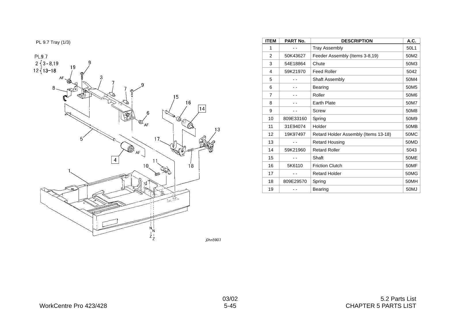
03/02 5.2 Parts ListWorkCentre Pro 423/428 5-45 CHAPTER 5 PARTS LIST
PL 9.7 Tray (1/3) ITEM PART No. DESCRIPTION A.C.
1 - - Tray Assembly 50L1
2 50K43627 Feeder Assembly (Items 3-8,19) 50M2
3 54E18864 Chute 50M3
4 59K21970 Feed Roller 5042
5 - - Shaft Assembly 50M4
6 - - Bearing 50M5
7 - - Roller 50M6
8 - - Earth Plate 50M7
9 - - Screw 50M8
10 809E33160 Spring 50M9
11 31E94074 Holder 50MB
12 19K97497 Retard Holder Assembly (Items 13-18) 50MC
13 - - Retard Housing 50MD
14 59K21960 Retard Roller 5043
15 - - Shaft 50ME
16 5K6110 Friction Clutch 50MF
17 - - Retard Holder 50MG
18 809E29570 Spring 50MH
19 - - Bearing 50MJ
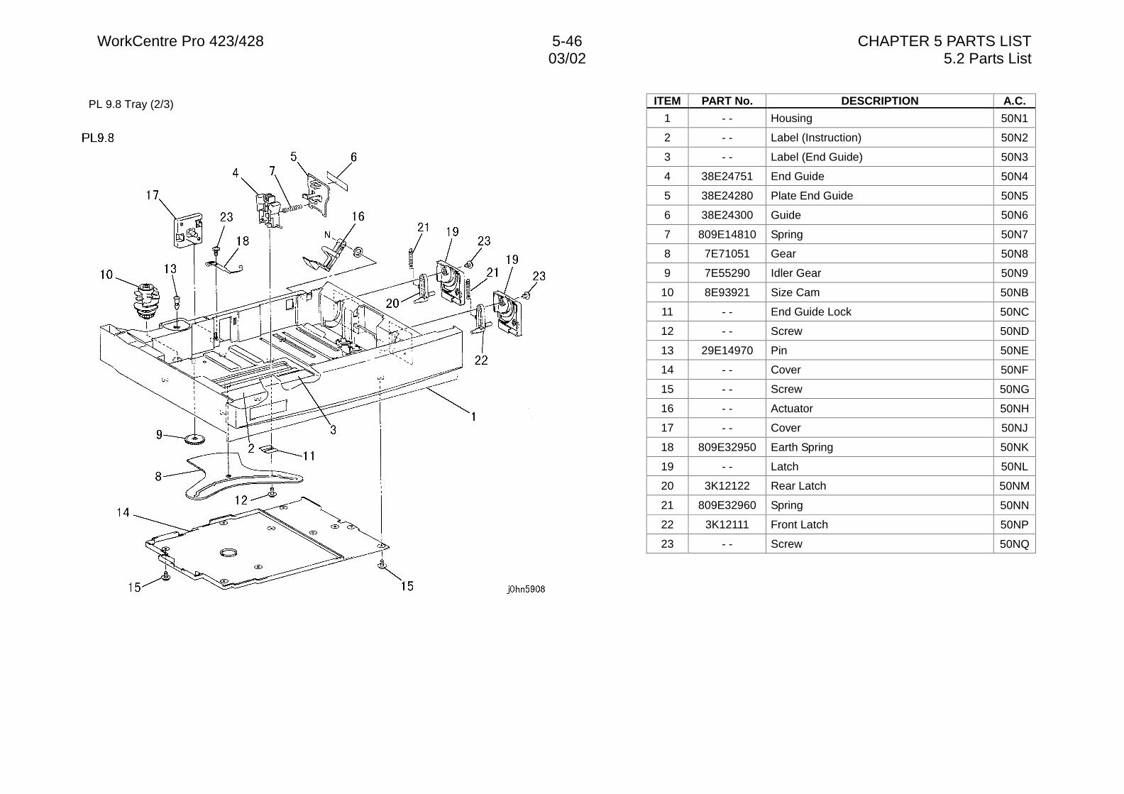
WorkCentre Pro 423/428 5-46 CHAPTER 5 PARTS LIST03/02 5.2 Parts List
PL 9.8 Tray (2/3) ITEM PART No. DESCRIPTION A.C.
1 - - Housing 50N1
2 - - Label (Instruction) 50N2
3 - - Label (End Guide) 50N3
4 38E24751 End Guide 50N4
5 38E24280 Plate End Guide 50N5
6 38E24300 Guide 50N6
7 809E14810 Spring 50N7
8 7E71051 Gear 50N8
9 7E55290 Idler Gear 50N9
10 8E93921 Size Cam 50NB
11 - - End Guide Lock 50NC
12 - - Screw 50ND
13 29E14970 Pin 50NE
14 - - Cover 50NF
15 - - Screw 50NG
16 - - Actuator 50NH
17 - - Cover 50NJ
18 809E32950 Earth Spring 50NK
19 - - Latch 50NL
20 3K12122 Rear Latch 50NM
21 809E32960 Spring 50NN
22 3K12111 Front Latch 50NP
23 - - Screw 50NQ
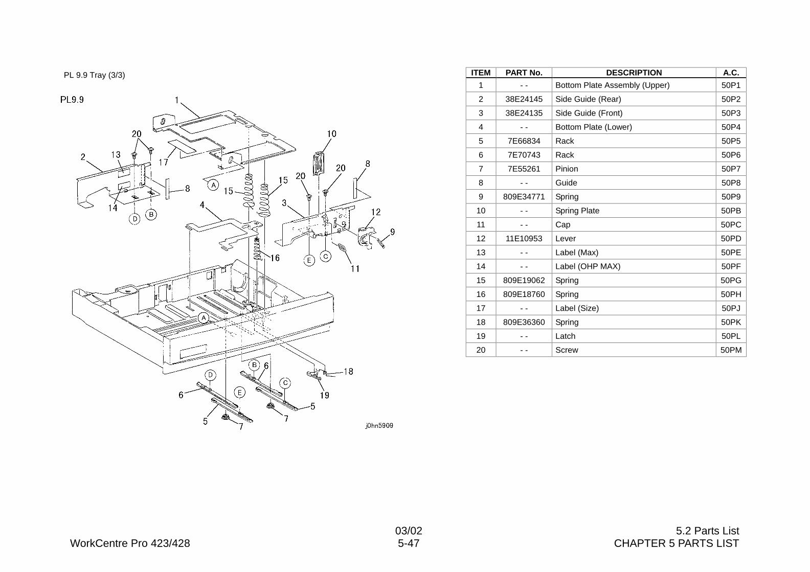
03/02 5.2 Parts ListWorkCentre Pro 423/428 5-47 CHAPTER 5 PARTS LIST
PL 9.9 Tray (3/3) ITEM PART No. DESCRIPTION A.C.
1 - - Bottom Plate Assembly (Upper) 50P1
2 38E24145 Side Guide (Rear) 50P2
3 38E24135 Side Guide (Front) 50P3
4 - - Bottom Plate (Lower) 50P4
5 7E66834 Rack 50P5
6 7E70743 Rack 50P6
7 7E55261 Pinion 50P7
8 - - Guide 50P8
9 809E34771 Spring 50P9
10 - - Spring Plate 50PB
11 - - Cap 50PC
12 11E10953 Lever 50PD
13 - - Label (Max) 50PE
14 - - Label (OHP MAX) 50PF
15 809E19062 Spring 50PG
16 809E18760 Spring 50PH
17 - - Label (Size) 50PJ
18 809E36360 Spring 50PK
19 - - Latch 50PL
20 - - Screw 50PM
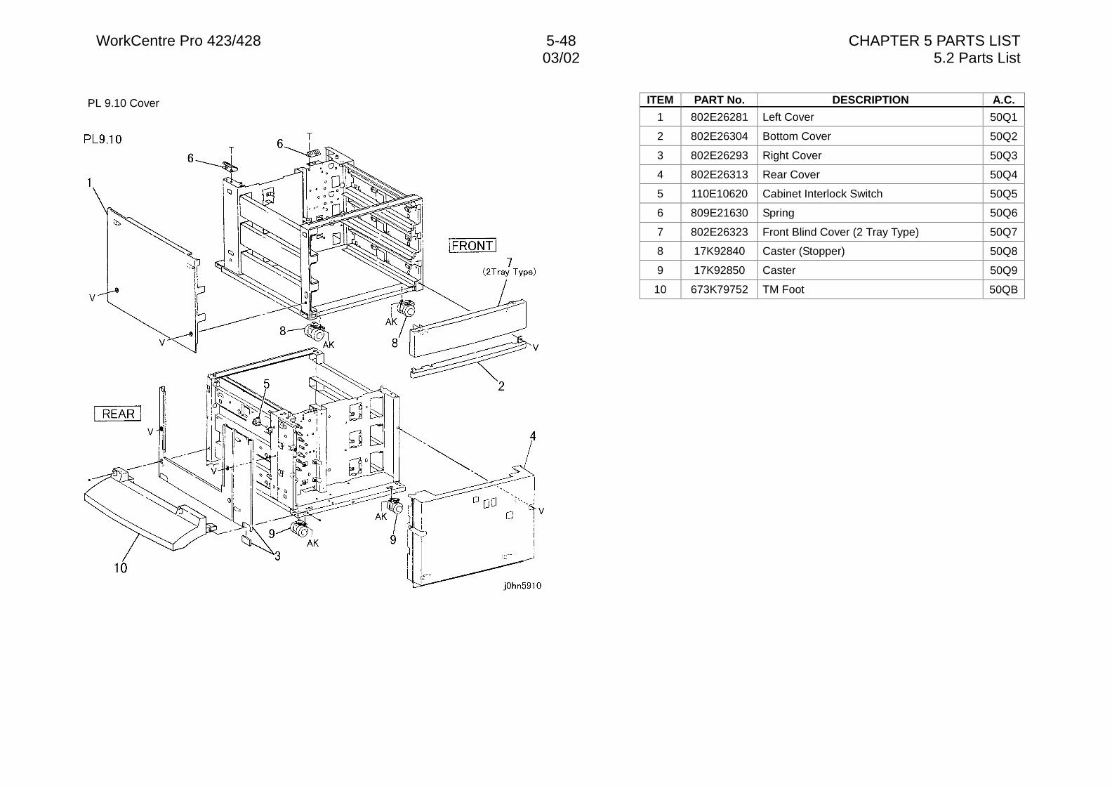
WorkCentre Pro 423/428 5-48 CHAPTER 5 PARTS LIST03/02 5.2 Parts List
PL 9.10 Cover ITEM PART No. DESCRIPTION A.C.
1 802E26281 Left Cover 50Q1
2 802E26304 Bottom Cover 50Q2
3 802E26293 Right Cover 50Q3
4 802E26313 Rear Cover 50Q4
5 110E10620 Cabinet Interlock Switch 50Q5
6 809E21630 Spring 50Q6
7 802E26323 Front Blind Cover (2 Tray Type) 50Q7
8 17K92840 Caster (Stopper) 50Q8
9 17K92850 Caster 50Q9
10 673K79752 TM Foot 50QB
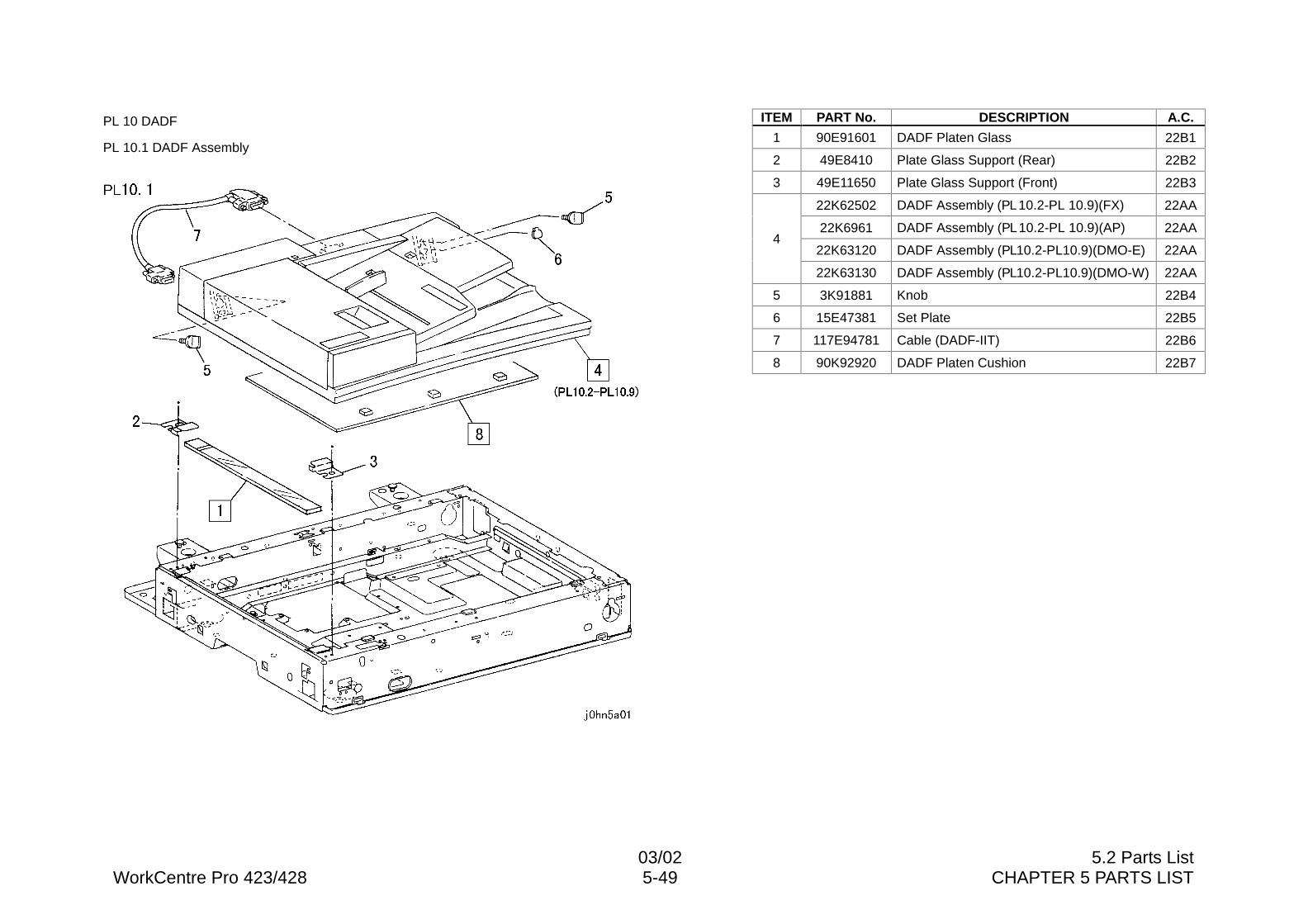
03/02 5.2 Parts ListWorkCentre Pro 423/428 5-49 CHAPTER 5 PARTS LIST
PL 10 DADF
PL 10.1 DADF Assembly
ITEM PART No. DESCRIPTION A.C.
1 90E91601 DADF Platen Glass 22B1
2 49E8410 Plate Glass Support (Rear) 22B2
3 49E11650 Plate Glass Support (Front) 22B3
22K62502 DADF Assembly (PL 10.2-PL 10.9)(FX) 22AA
22K6961 DADF Assembly (PL 10.2-PL 10.9)(AP) 22AA
22K63120 DADF Assembly (PL10.2-PL10.9)(DMO-E) 22AA4
22K63130 DADF Assembly (PL10.2-PL10.9)(DMO-W) 22AA
5 3K91881 Knob 22B4
6 15E47381 Set Plate 22B5
7 117E94781 Cable (DADF-IIT) 22B6
8 90K92920 DADF Platen Cushion 22B7
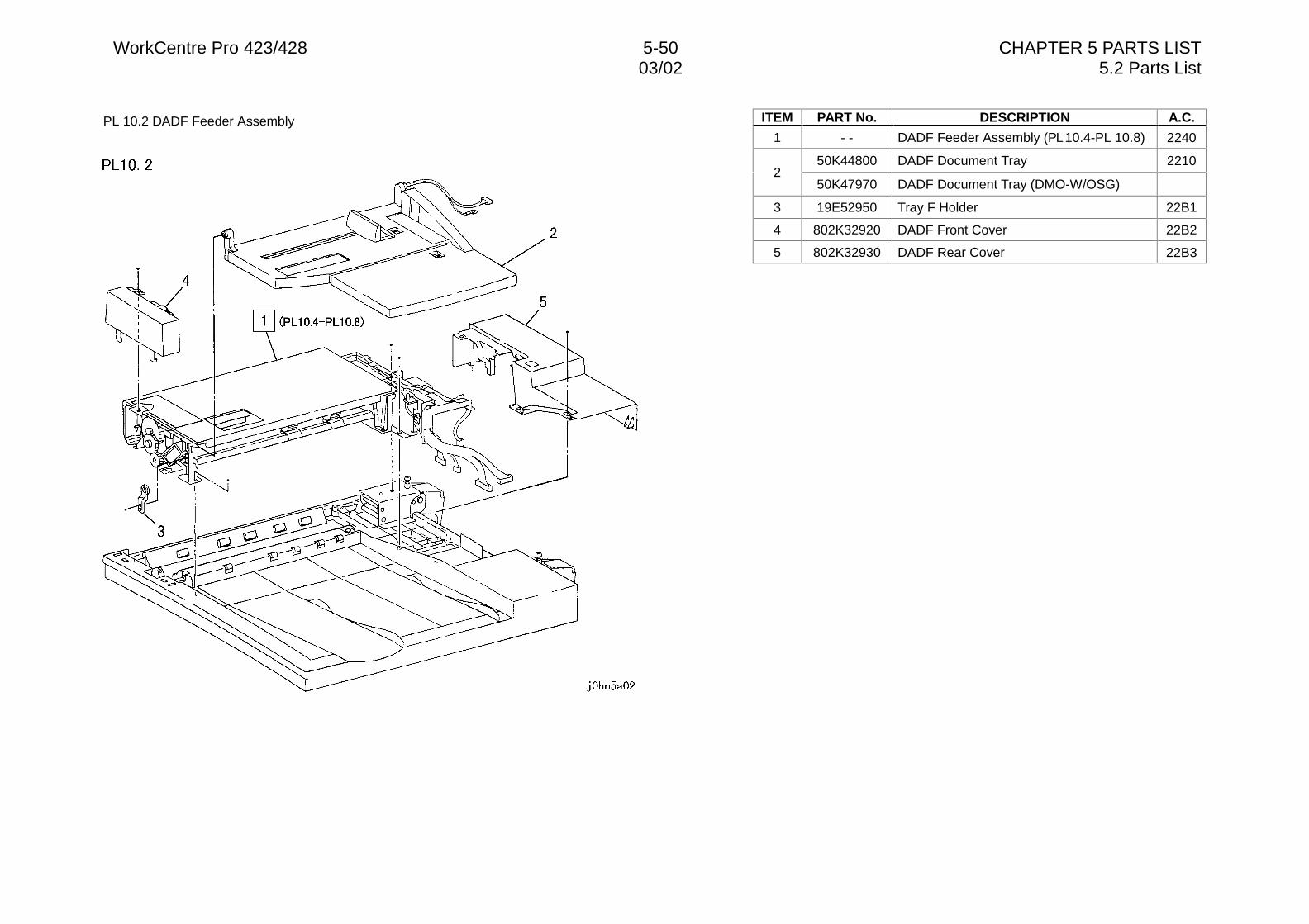
WorkCentre Pro 423/428 5-50 CHAPTER 5 PARTS LIST03/02 5.2 Parts List
PL 10.2 DADF Feeder Assembly ITEM PART No. DESCRIPTION A.C.
1 - - DADF Feeder Assembly (PL 10.4-PL 10.8) 2240
50K44800 DADF Document Tray 22102
50K47970 DADF Document Tray (DMO-W/OSG)
3 19E52950 Tray F Holder 22B1
4 802K32920 DADF Front Cover 22B2
5 802K32930 DADF Rear Cover 22B3
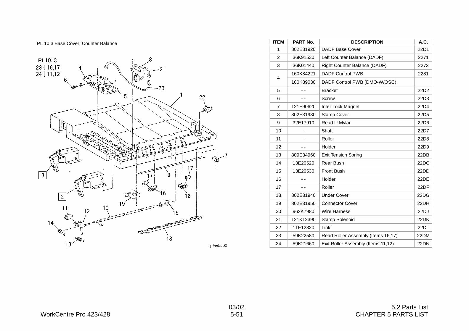
03/02 5.2 Parts ListWorkCentre Pro 423/428 5-51 CHAPTER 5 PARTS LIST
PL 10.3 Base Cover, Counter Balance ITEM PART No. DESCRIPTION A.C.
1 802E31920 DADF Base Cover 22D1
2 36K91530 Left Counter Balance (DADF) 2271
3 36K01440 Right Counter Balance (DADF) 2273
160K84221 DADF Control PWB 22814
160K89030 DADF Control PWB (DMO-W/OSC)
5 - - Bracket 22D2
6 - - Screw 22D3
7 121E90620 Inter Lock Magnet 22D4
8 802E31930 Stamp Cover 22D5
9 32E17910 Read U Mylar 22D6
10 - - Shaft 22D7
11 - - Roller 22D8
12 - - Holder 22D9
13 809E34960 Exit Tension Spring 22DB
14 13E20520 Rear Bush 22DC
15 13E20530 Front Bush 22DD
16 - - Holder 22DE
17 - - Roller 22DF
18 802E31940 Under Cover 22DG
19 802E31950 Connector Cover 22DH
20 962K7980 Wire Harness 22DJ
21 121K12390 Stamp Solenoid 22DK
22 11E12320 Link 22DL
23 59K22580 Read Roller Assembly (Items 16,17) 22DM
24 59K21660 Exit Roller Assembly (Items 11,12) 22DN
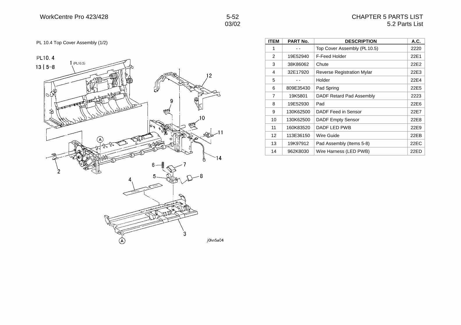
WorkCentre Pro 423/428 5-52 CHAPTER 5 PARTS LIST03/02 5.2 Parts List
PL 10.4 Top Cover Assembly (1/2) ITEM PART No. DESCRIPTION A.C.
1 - - Top Cover Assembly (PL 10.5) 2220
2 19E52940 F-Feed Holder 22E1
3 38K86062 Chute 22E2
4 32E17920 Reverse Registration Mylar 22E3
5 - - Holder 22E4
6 809E35430 Pad Spring 22E5
7 19K5801 DADF Retard Pad Assembly 2223
8 19E52930 Pad 22E6
9 130K62500 DADF Feed in Sensor 22E7
10 130K62500 DADF Empty Sensor 22E8
11 160K83520 DADF LED PWB 22E9
12 113E36150 Wire Guide 22EB
13 19K97912 Pad Assembly (Items 5-8) 22EC
14 962K8030 Wire Harness (LED PWB) 22ED
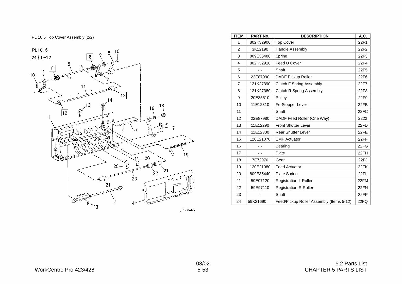
03/02 5.2 Parts ListWorkCentre Pro 423/428 5-53 CHAPTER 5 PARTS LIST
PL 10.5 Top Cover Assembly (2/2) ITEM PART No. DESCRIPTION A.C.
1 802K32900 Top Cover 22F1
2 3K12190 Handle Assembly 22F2
3 809E35480 Spring 22F3
4 802K32910 Feed U Cover 22F4
5 - - Shaft 22F5
6 22E87990 DADF Pickup Roller 22F6
7 121K27390 Clutch F Spring Assembly 22F7
8 121K27380 Clutch R Spring Assembly 22F8
9 20E35510 Pulley 22F9
10 11E12310 Fe-Stopper Lever 22FB
11 - - Shaft 22FC
12 22E87980 DADF Feed Roller (One Way) 2222
13 11E12290 Front Shutter Lever 22FD
14 11E12300 Rear Shutter Lever 22FE
15 120E21070 EMP Actuator 22FF
16 - - Bearing 22FG
17 - - Plate 22FH
18 7E72970 Gear 22FJ
19 120E21080 Feed Actuator 22FK
20 809E35440 Plate Spring 22FL
21 59E97120 Registration-L Roller 22FM
22 59E97110 Registration-R Roller 22FN
23 - - Shaft 22FP
24 59K21690 Feed/Pickup Roller Assembly (Items 5-12) 22FQ
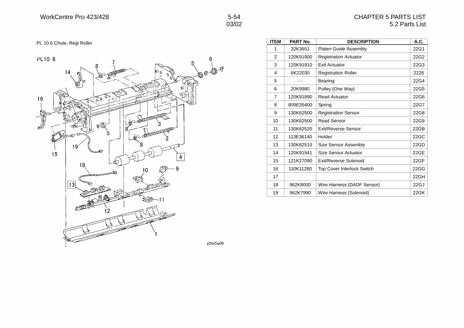
WorkCentre Pro 423/428 5-54 CHAPTER 5 PARTS LIST03/02 5.2 Parts List
PL 10.6 Chute, Regi Roller ITEM PART No. DESCRIPTION A.C.
1 32K3651 Platen Guide Assembly 22G1
2 120K91900 Registration Actuator 22G2
3 120K91910 Exit Actuator 22G3
4 6K22030 Registration Roller 2226
5 - - Bearing 22G4
6 20K9980 Pulley (One Way) 22G5
7 120K91890 Read Actuator 22G6
8 809E35400 Spring 22G7
9 130K62500 Registration Sensor 22G8
10 130K62500 Read Sensor 22G9
11 130K62520 Exit/Reverse Sensor 22GB
12 113E36140 Holder 22GC
13 130K62510 Size Sensor Assembly 22GD
14 120K91941 Size Sensor Actuator 22GE
15 121K27090 Exit/Reverse Solenoid 22GF
16 110K11280 Top Cover Interlock Switch 22GG
17 22GH
18 962K8000 Wire Harness (DADF Sensor) 22GJ
19 962K7990 Wire Harness (Solenoid) 22GK
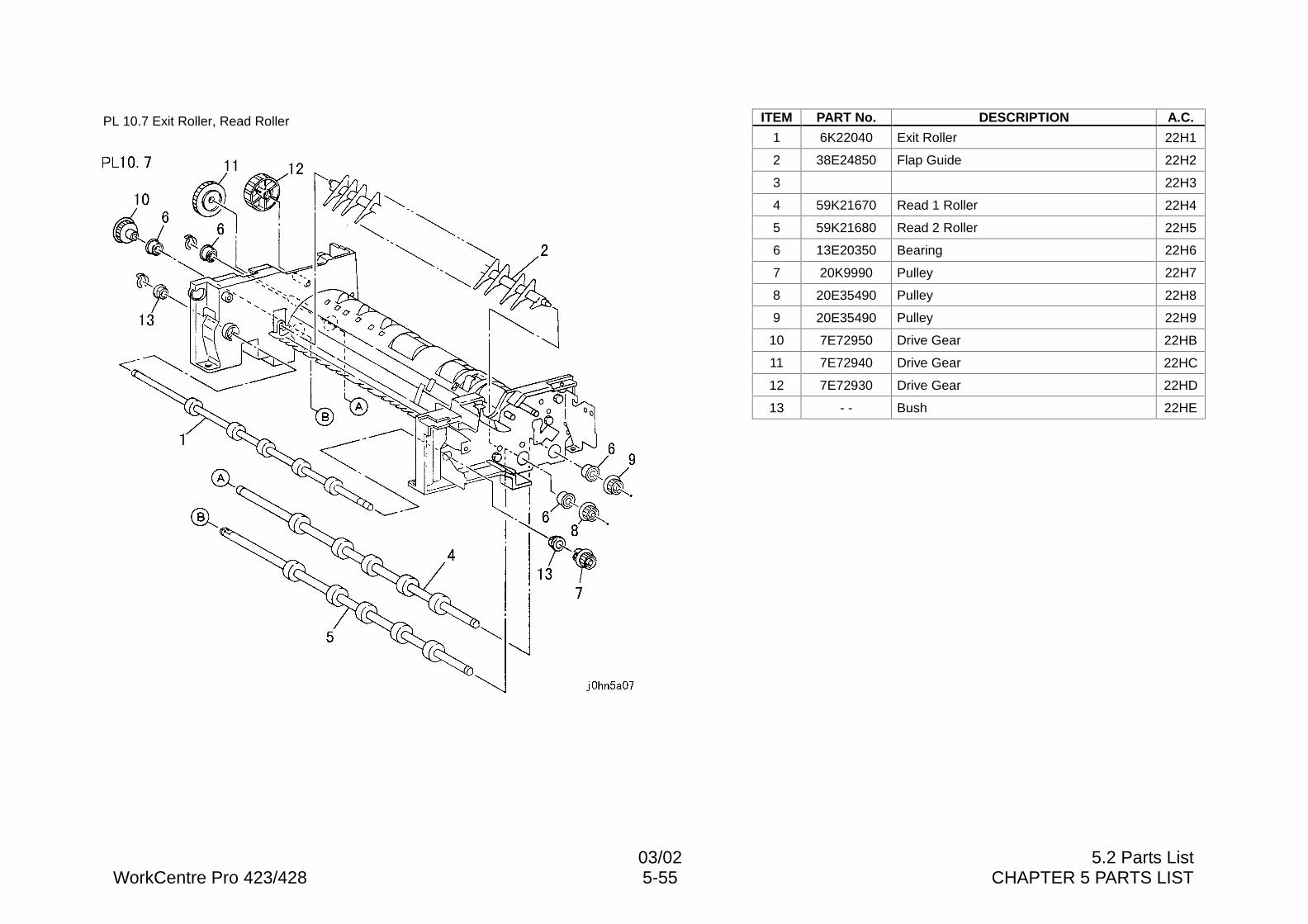
03/02 5.2 Parts ListWorkCentre Pro 423/428 5-55 CHAPTER 5 PARTS LIST
PL 10.7 Exit Roller, Read Roller ITEM PART No. DESCRIPTION A.C.
1 6K22040 Exit Roller 22H1
2 38E24850 Flap Guide 22H2
3 22H3
4 59K21670 Read 1 Roller 22H4
5 59K21680 Read 2 Roller 22H5
6 13E20350 Bearing 22H6
7 20K9990 Pulley 22H7
8 20E35490 Pulley 22H8
9 20E35490 Pulley 22H9
10 7E72950 Drive Gear 22HB
11 7E72940 Drive Gear 22HC
12 7E72930 Drive Gear 22HD
13 - - Bush 22HE
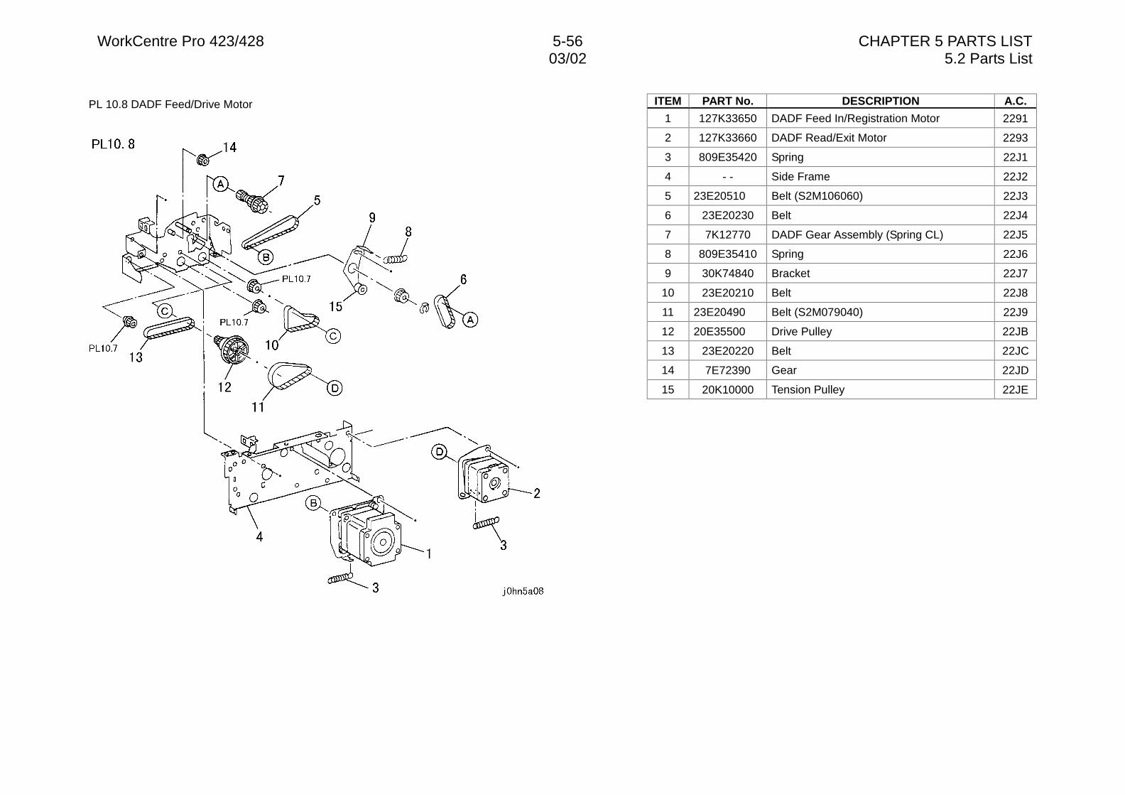
WorkCentre Pro 423/428 5-56 CHAPTER 5 PARTS LIST03/02 5.2 Parts List
PL 10.8 DADF Feed/Drive Motor ITEM PART No. DESCRIPTION A.C.
1 127K33650 DADF Feed In/Registration Motor 2291
2 127K33660 DADF Read/Exit Motor 2293
3 809E35420 Spring 22J1
4 - - Side Frame 22J2
5 23E20510 Belt (S2M106060) 22J3
6 23E20230 Belt 22J4
7 7K12770 DADF Gear Assembly (Spring CL) 22J5
8 809E35410 Spring 22J6
9 30K74840 Bracket 22J7
10 23E20210 Belt 22J8
11 23E20490 Belt (S2M079040) 22J9
12 20E35500 Drive Pulley 22JB
13 23E20220 Belt 22JC
14 7E72390 Gear 22JD
15 20K10000 Tension Pulley 22JE
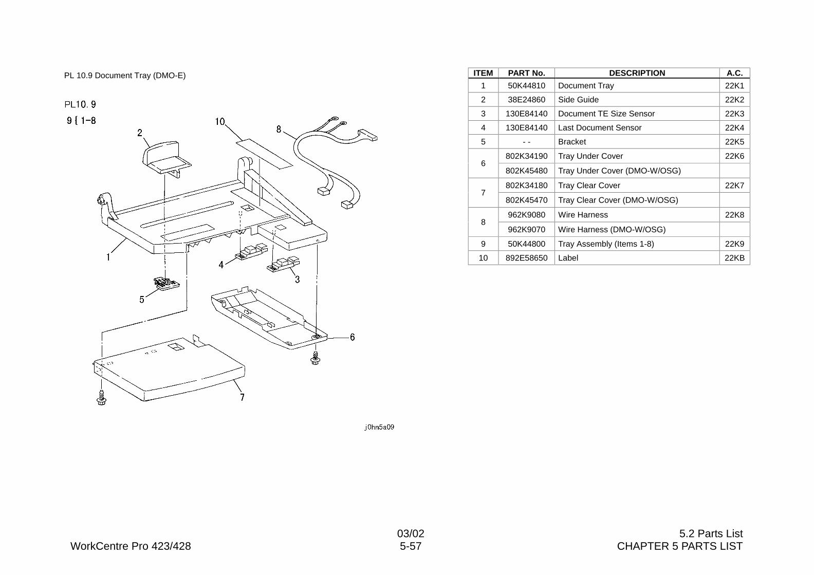
03/02 5.2 Parts ListWorkCentre Pro 423/428 5-57 CHAPTER 5 PARTS LIST
PL 10.9 Document Tray (DMO-E) ITEM PART No. DESCRIPTION A.C.
1 50K44810 Document Tray 22K1
2 38E24860 Side Guide 22K2
3 130E84140 Document TE Size Sensor 22K3
4 130E84140 Last Document Sensor 22K4
5 - - Bracket 22K5
802K34190 Tray Under Cover 22K66
802K45480 Tray Under Cover (DMO-W/OSG)
802K34180 Tray Clear Cover 22K77
802K45470 Tray Clear Cover (DMO-W/OSG)
962K9080 Wire Harness 22K88
962K9070 Wire Harness (DMO-W/OSG)
9 50K44800 Tray Assembly (Items 1-8) 22K9
10 892E58650 Label 22KB
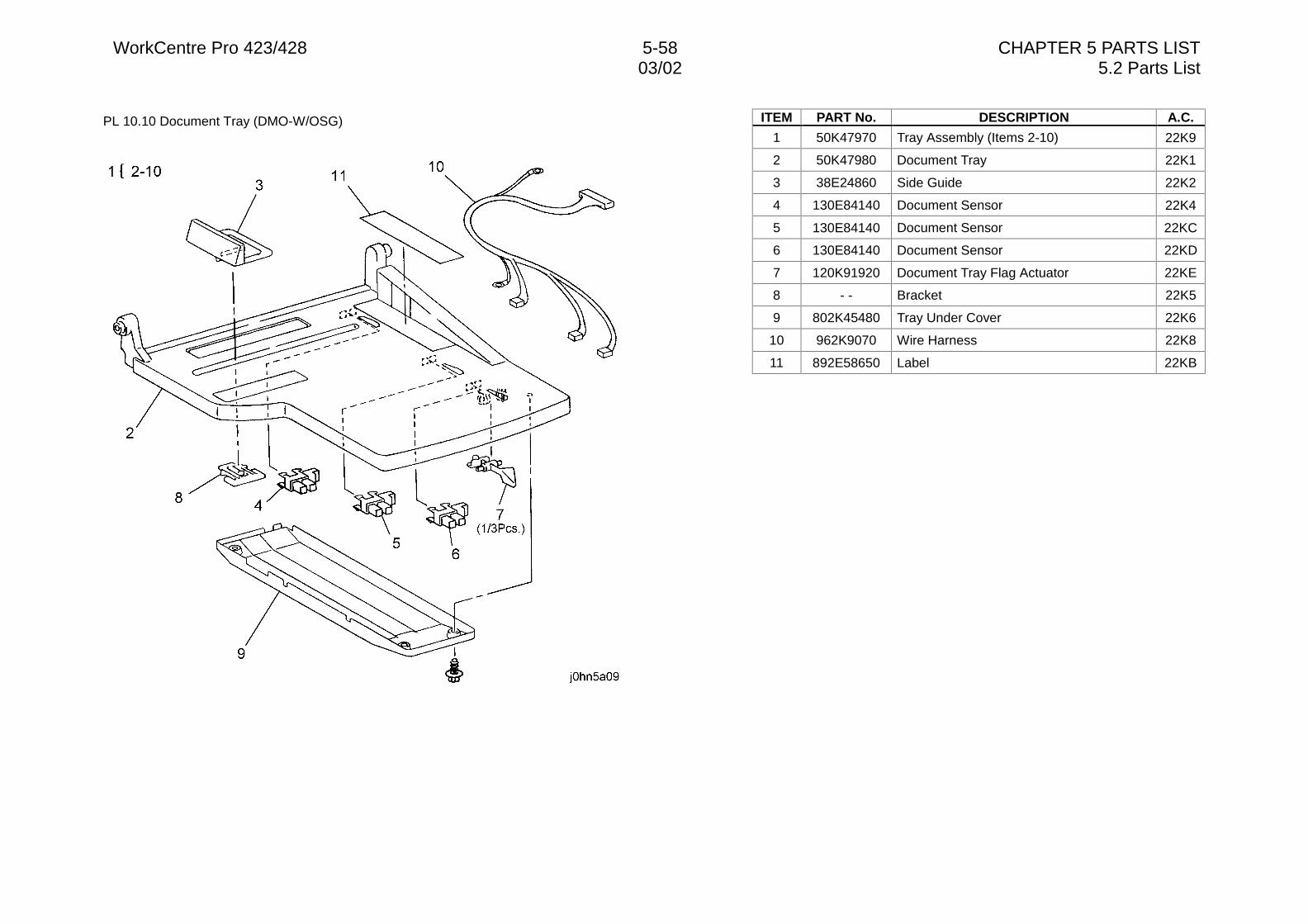
WorkCentre Pro 423/428 5-58 CHAPTER 5 PARTS LIST03/02 5.2 Parts List
PL 10.10 Document Tray (DMO-W/OSG) ITEM PART No. DESCRIPTION A.C.
1 50K47970 Tray Assembly (Items 2-10) 22K9
2 50K47980 Document Tray 22K1
3 38E24860 Side Guide 22K2
4 130E84140 Document Sensor 22K4
5 130E84140 Document Sensor 22KC
6 130E84140 Document Sensor 22KD
7 120K91920 Document Tray Flag Actuator 22KE
8 - - Bracket 22K5
9 802K45480 Tray Under Cover 22K6
10 962K9070 Wire Harness 22K8
11 892E58650 Label 22KB
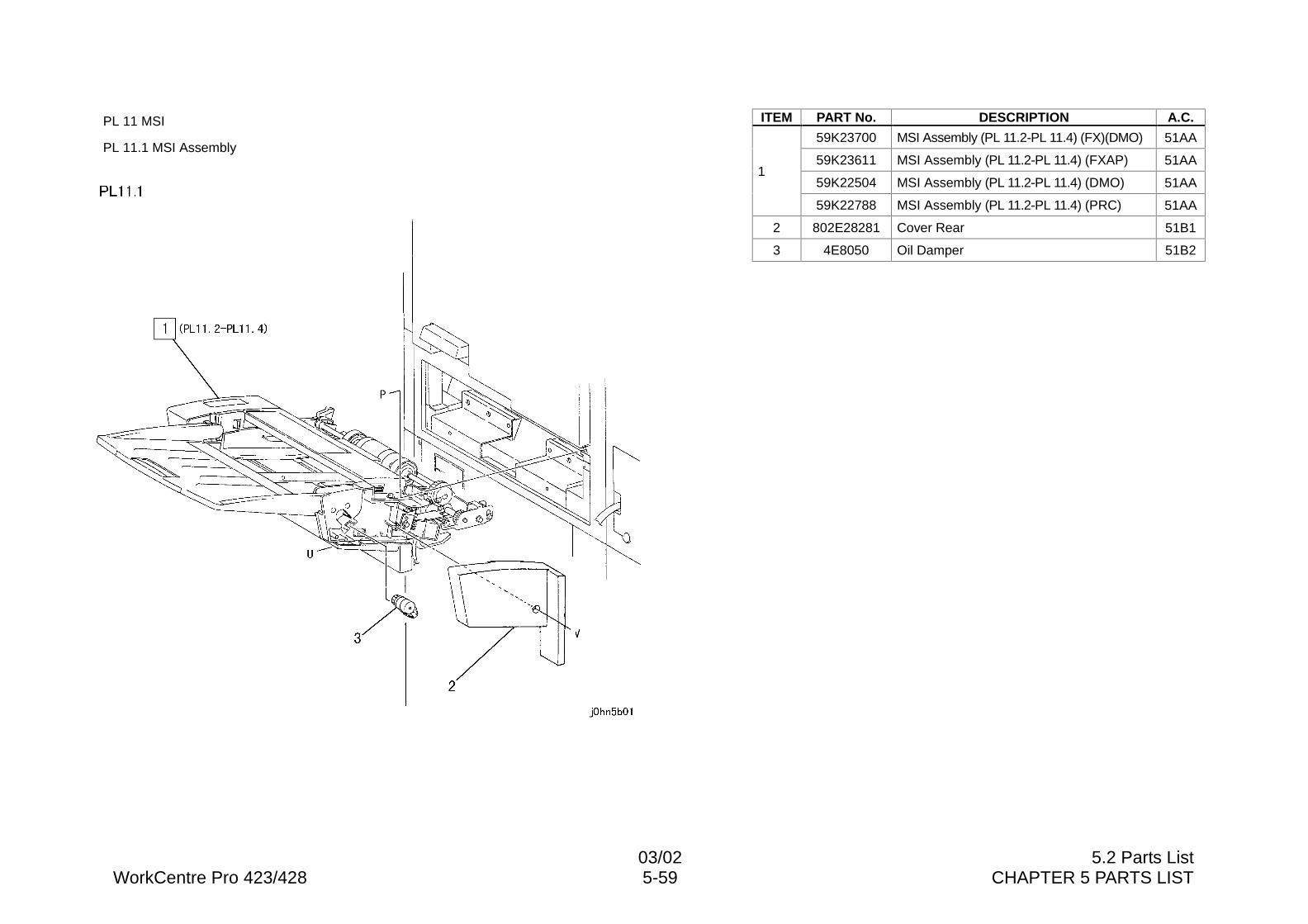
03/02 5.2 Parts ListWorkCentre Pro 423/428 5-59 CHAPTER 5 PARTS LIST
PL 11 MSI
PL 11.1 MSI Assembly
ITEM PART No. DESCRIPTION A.C.
59K23700 MSI Assembly (PL 11.2-PL 11.4) (FX)(DMO) 51AA
59K23611 MSI Assembly (PL 11.2-PL 11.4) (FXAP) 51AA
59K22504 MSI Assembly (PL 11.2-PL 11.4) (DMO) 51AA1
59K22788 MSI Assembly (PL 11.2-PL 11.4) (PRC) 51AA
2 802E28281 Cover Rear 51B1
3 4E8050 Oil Damper 51B2
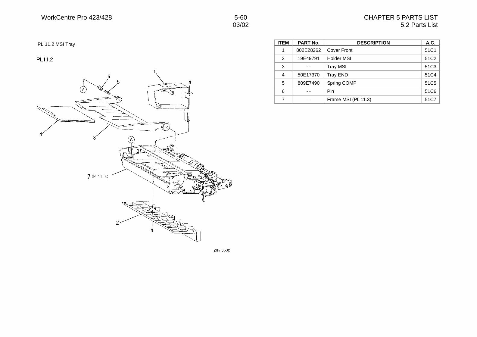
WorkCentre Pro 423/428 5-60 CHAPTER 5 PARTS LIST03/02 5.2 Parts List
PL 11.2 MSI Tray ITEM PART No. DESCRIPTION A.C.
1 802E28262 Cover Front 51C1
2 19E49791 Holder MSI 51C2
3 - - Tray MSI 51C3
4 50E17370 Tray END 51C4
5 809E7490 Spring COMP 51C5
6 - - Pin 51C6
7 - - Frame MSI (PL 11.3) 51C7
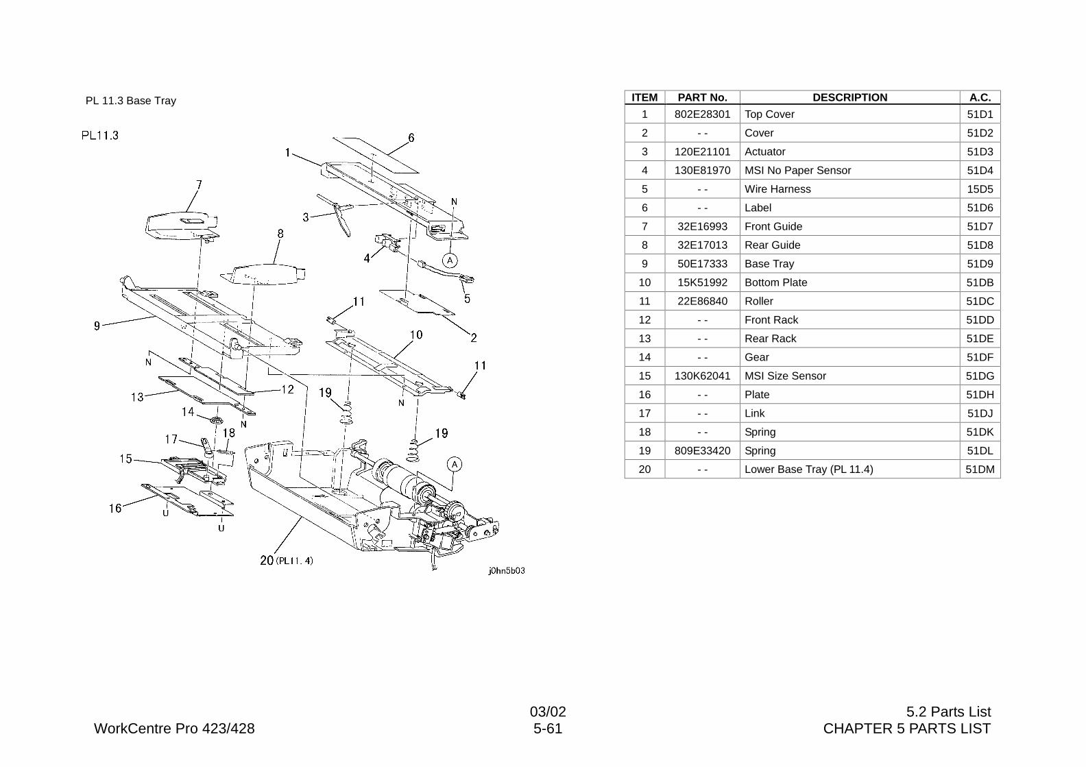
03/02 5.2 Parts ListWorkCentre Pro 423/428 5-61 CHAPTER 5 PARTS LIST
PL 11.3 Base Tray ITEM PART No. DESCRIPTION A.C.
1 802E28301 Top Cover 51D1
2 - - Cover 51D2
3 120E21101 Actuator 51D3
4 130E81970 MSI No Paper Sensor 51D4
5 - - Wire Harness 15D5
6 - - Label 51D6
7 32E16993 Front Guide 51D7
8 32E17013 Rear Guide 51D8
9 50E17333 Base Tray 51D9
10 15K51992 Bottom Plate 51DB
11 22E86840 Roller 51DC
12 - - Front Rack 51DD
13 - - Rear Rack 51DE
14 - - Gear 51DF
15 130K62041 MSI Size Sensor 51DG
16 - - Plate 51DH
17 - - Link 51DJ
18 - - Spring 51DK
19 809E33420 Spring 51DL
20 - - Lower Base Tray (PL 11.4) 51DM
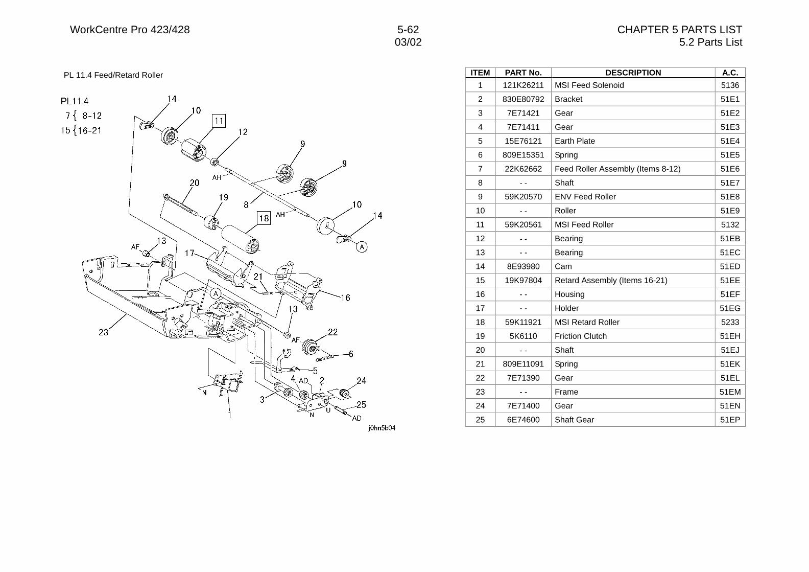
WorkCentre Pro 423/428 5-62 CHAPTER 5 PARTS LIST03/02 5.2 Parts List
PL 11.4 Feed/Retard Roller ITEM PART No. DESCRIPTION A.C.
1 121K26211 MSI Feed Solenoid 5136
2 830E80792 Bracket 51E1
3 7E71421 Gear 51E2
4 7E71411 Gear 51E3
5 15E76121 Earth Plate 51E4
6 809E15351 Spring 51E5
7 22K62662 Feed Roller Assembly (Items 8-12) 51E6
8 - - Shaft 51E7
9 59K20570 ENV Feed Roller 51E8
10 - - Roller 51E9
11 59K20561 MSI Feed Roller 5132
12 - - Bearing 51EB
13 - - Bearing 51EC
14 8E93980 Cam 51ED
15 19K97804 Retard Assembly (Items 16-21) 51EE
16 - - Housing 51EF
17 - - Holder 51EG
18 59K11921 MSI Retard Roller 5233
19 5K6110 Friction Clutch 51EH
20 - - Shaft 51EJ
21 809E11091 Spring 51EK
22 7E71390 Gear 51EL
23 - - Frame 51EM
24 7E71400 Gear 51EN
25 6E74600 Shaft Gear 51EP
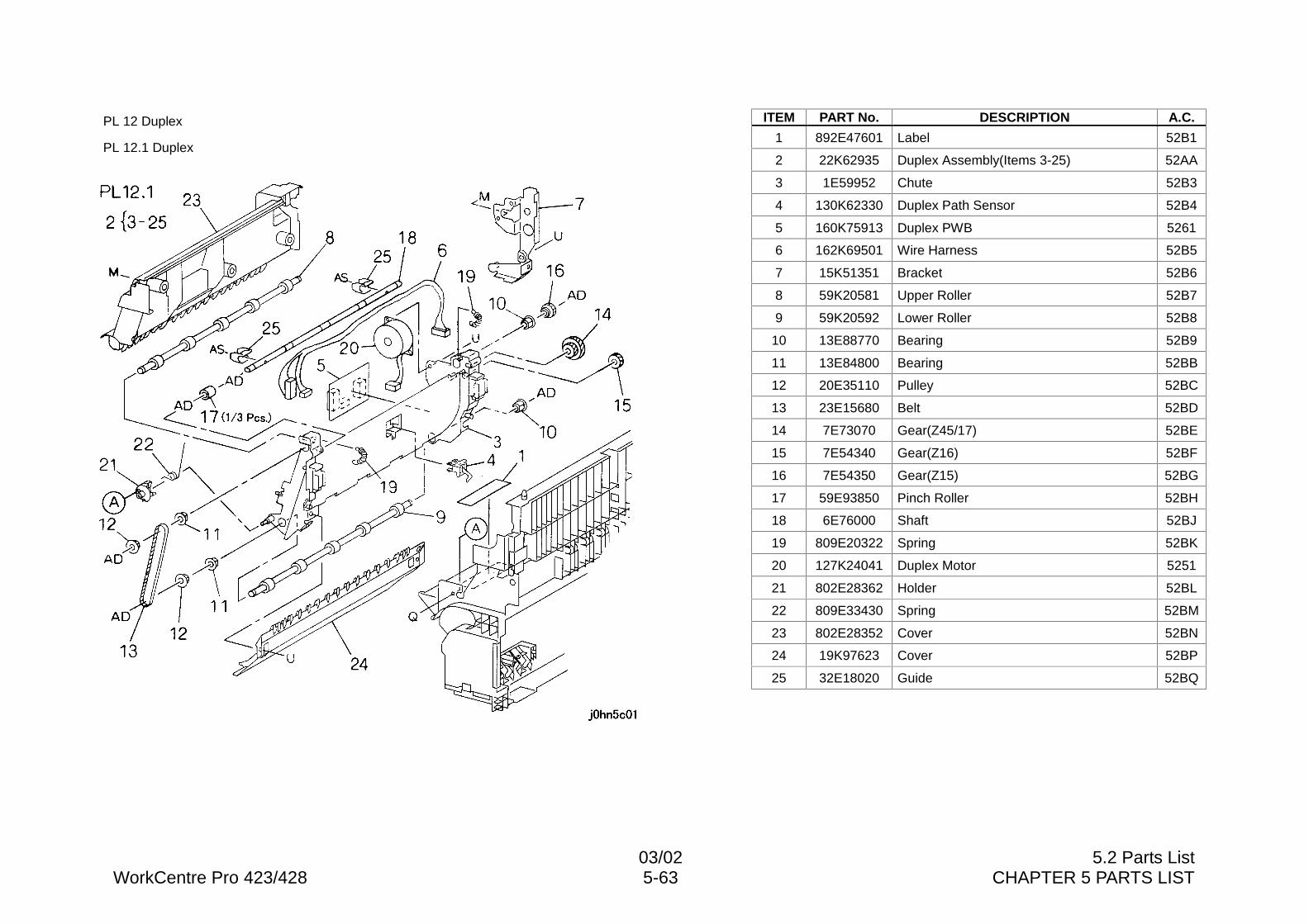
03/02 5.2 Parts ListWorkCentre Pro 423/428 5-63 CHAPTER 5 PARTS LIST
PL 12 Duplex
PL 12.1 Duplex
ITEM PART No. DESCRIPTION A.C.
1 892E47601 Label 52B1
2 22K62935 Duplex Assembly(Items 3-25) 52AA
3 1E59952 Chute 52B3
4 130K62330 Duplex Path Sensor 52B4
5 160K75913 Duplex PWB 5261
6 162K69501 Wire Harness 52B5
7 15K51351 Bracket 52B6
8 59K20581 Upper Roller 52B7
9 59K20592 Lower Roller 52B8
10 13E88770 Bearing 52B9
11 13E84800 Bearing 52BB
12 20E35110 Pulley 52BC
13 23E15680 Belt 52BD
14 7E73070 Gear(Z45/17) 52BE
15 7E54340 Gear(Z16) 52BF
16 7E54350 Gear(Z15) 52BG
17 59E93850 Pinch Roller 52BH
18 6E76000 Shaft 52BJ
19 809E20322 Spring 52BK
20 127K24041 Duplex Motor 5251
21 802E28362 Holder 52BL
22 809E33430 Spring 52BM
23 802E28352 Cover 52BN
24 19K97623 Cover 52BP
25 32E18020 Guide 52BQ
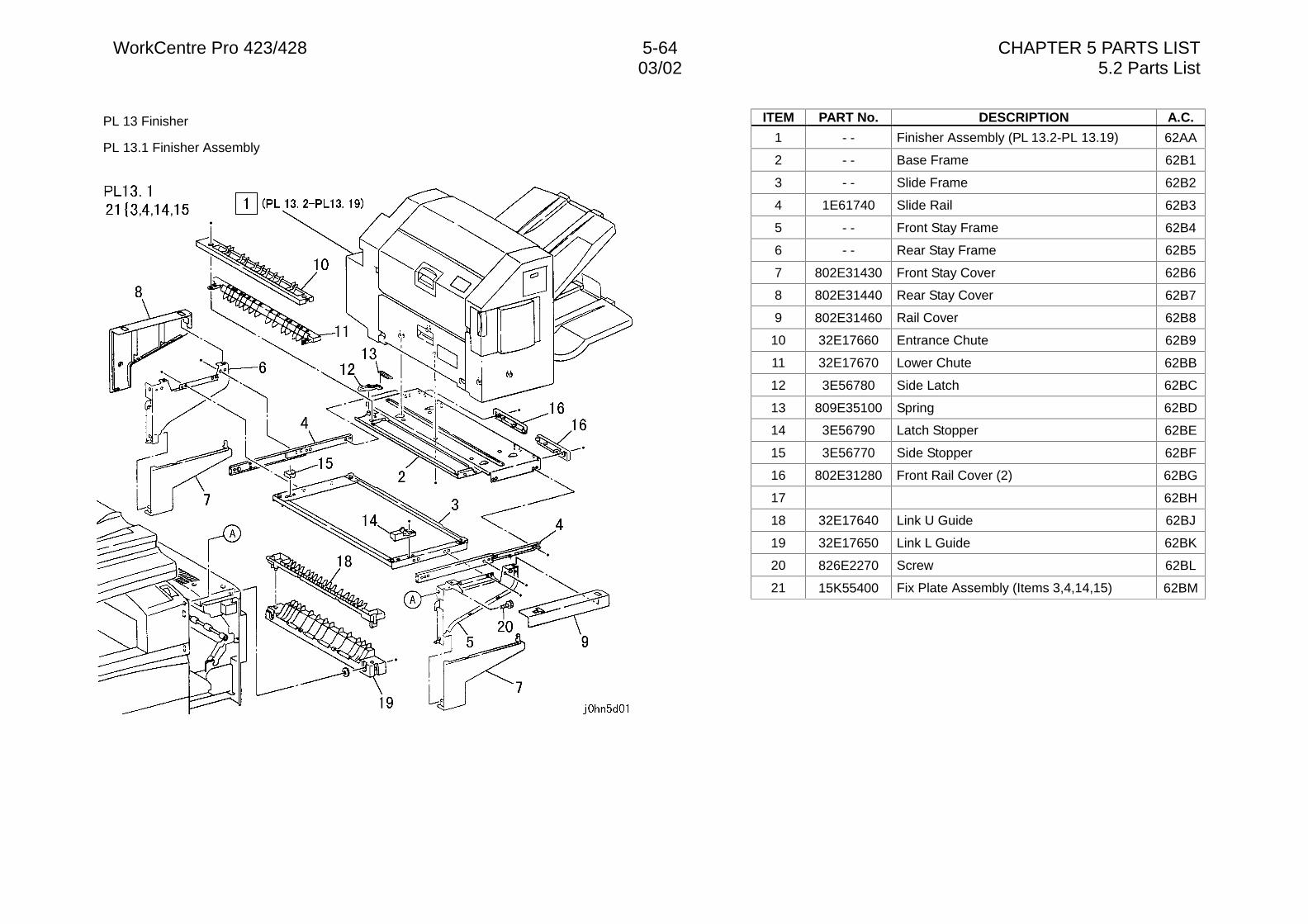
WorkCentre Pro 423/428 5-64 CHAPTER 5 PARTS LIST03/02 5.2 Parts List
PL 13 Finisher
PL 13.1 Finisher Assembly
ITEM PART No. DESCRIPTION A.C.
1 - - Finisher Assembly (PL 13.2-PL 13.19) 62AA
2 - - Base Frame 62B1
3 - - Slide Frame 62B2
4 1E61740 Slide Rail 62B3
5 - - Front Stay Frame 62B4
6 - - Rear Stay Frame 62B5
7 802E31430 Front Stay Cover 62B6
8 802E31440 Rear Stay Cover 62B7
9 802E31460 Rail Cover 62B8
10 32E17660 Entrance Chute 62B9
11 32E17670 Lower Chute 62BB
12 3E56780 Side Latch 62BC
13 809E35100 Spring 62BD
14 3E56790 Latch Stopper 62BE
15 3E56770 Side Stopper 62BF
16 802E31280 Front Rail Cover (2) 62BG
17 62BH
18 32E17640 Link U Guide 62BJ
19 32E17650 Link L Guide 62BK
20 826E2270 Screw 62BL
21 15K55400 Fix Plate Assembly (Items 3,4,14,15) 62BM
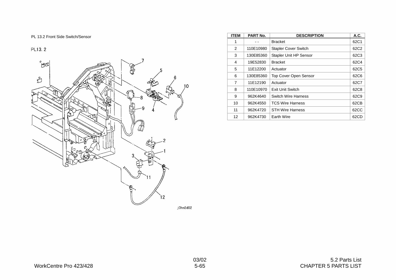
03/02 5.2 Parts ListWorkCentre Pro 423/428 5-65 CHAPTER 5 PARTS LIST
PL 13.2 Front Side Switch/Sensor ITEM PART No. DESCRIPTION A.C.
1 - - Bracket 62C1
2 110E10980 Stapler Cover Switch 62C2
3 130E85360 Stapler Unit HP Sensor 62C3
4 19E52830 Bracket 62C4
5 11E12200 Actuator 62C5
6 130E85360 Top Cover Open Sensor 62C6
7 11E12190 Actuator 62C7
8 110E10970 Exit Unit Switch 62C8
9 962K4640 Switch Wire Harness 62C9
10 962K4550 TCS Wire Harness 62CB
11 962K4720 STH Wire Harness 62CC
12 962K4730 Earth Wire 62CD
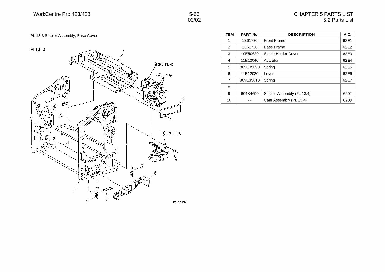
WorkCentre Pro 423/428 5-66 CHAPTER 5 PARTS LIST03/02 5.2 Parts List
PL 13.3 Stapler Assembly, Base Cover ITEM PART No. DESCRIPTION A.C.
1 1E61730 Front Frame 62E1
2 1E61720 Base Frame 62E2
3 19E50620 Staple Holder Cover 62E3
4 11E12040 Actuator 62E4
5 809E35090 Spring 62E5
6 11E12020 Lever 62E6
7 809E35010 Spring 62E7
8
9 604K4690 Stapler Assembly (PL 13.4) 6202
10 - - Cam Assembly (PL 13.4) 6203
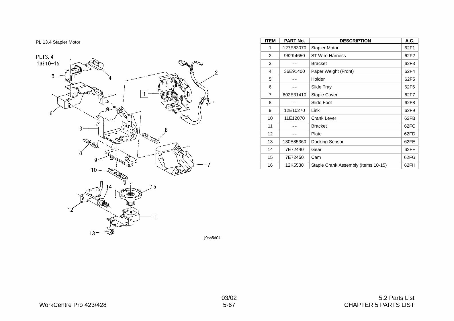
03/02 5.2 Parts ListWorkCentre Pro 423/428 5-67 CHAPTER 5 PARTS LIST
PL 13.4 Stapler Motor ITEM PART No. DESCRIPTION A.C.
1 127E83070 Stapler Motor 62F1
2 962K4650 ST Wire Harness 62F2
3 - - Bracket 62F3
4 36E91400 Paper Weight (Front) 62F4
5 - - Holder 62F5
6 - - Slide Tray 62F6
7 802E31410 Staple Cover 62F7
8 - - Slide Foot 62F8
9 12E10270 Link 62F9
10 11E12070 Crank Lever 62FB
11 - - Bracket 62FC
12 - - Plate 62FD
13 130E85360 Docking Sensor 62FE
14 7E72440 Gear 62FF
15 7E72450 Cam 62FG
16 12K5530 Staple Crank Assembly (Items 10-15) 62FH
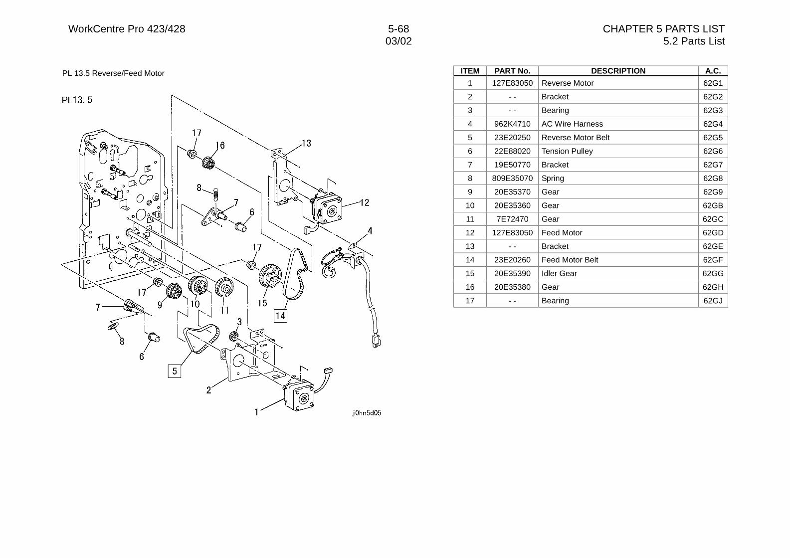
WorkCentre Pro 423/428 5-68 CHAPTER 5 PARTS LIST03/02 5.2 Parts List
PL 13.5 Reverse/Feed Motor ITEM PART No. DESCRIPTION A.C.
1 127E83050 Reverse Motor 62G1
2 - - Bracket 62G2
3 - - Bearing 62G3
4 962K4710 AC Wire Harness 62G4
5 23E20250 Reverse Motor Belt 62G5
6 22E88020 Tension Pulley 62G6
7 19E50770 Bracket 62G7
8 809E35070 Spring 62G8
9 20E35370 Gear 62G9
10 20E35360 Gear 62GB
11 7E72470 Gear 62GC
12 127E83050 Feed Motor 62GD
13 - - Bracket 62GE
14 23E20260 Feed Motor Belt 62GF
15 20E35390 Idler Gear 62GG
16 20E35380 Gear 62GH
17 - - Bearing 62GJ
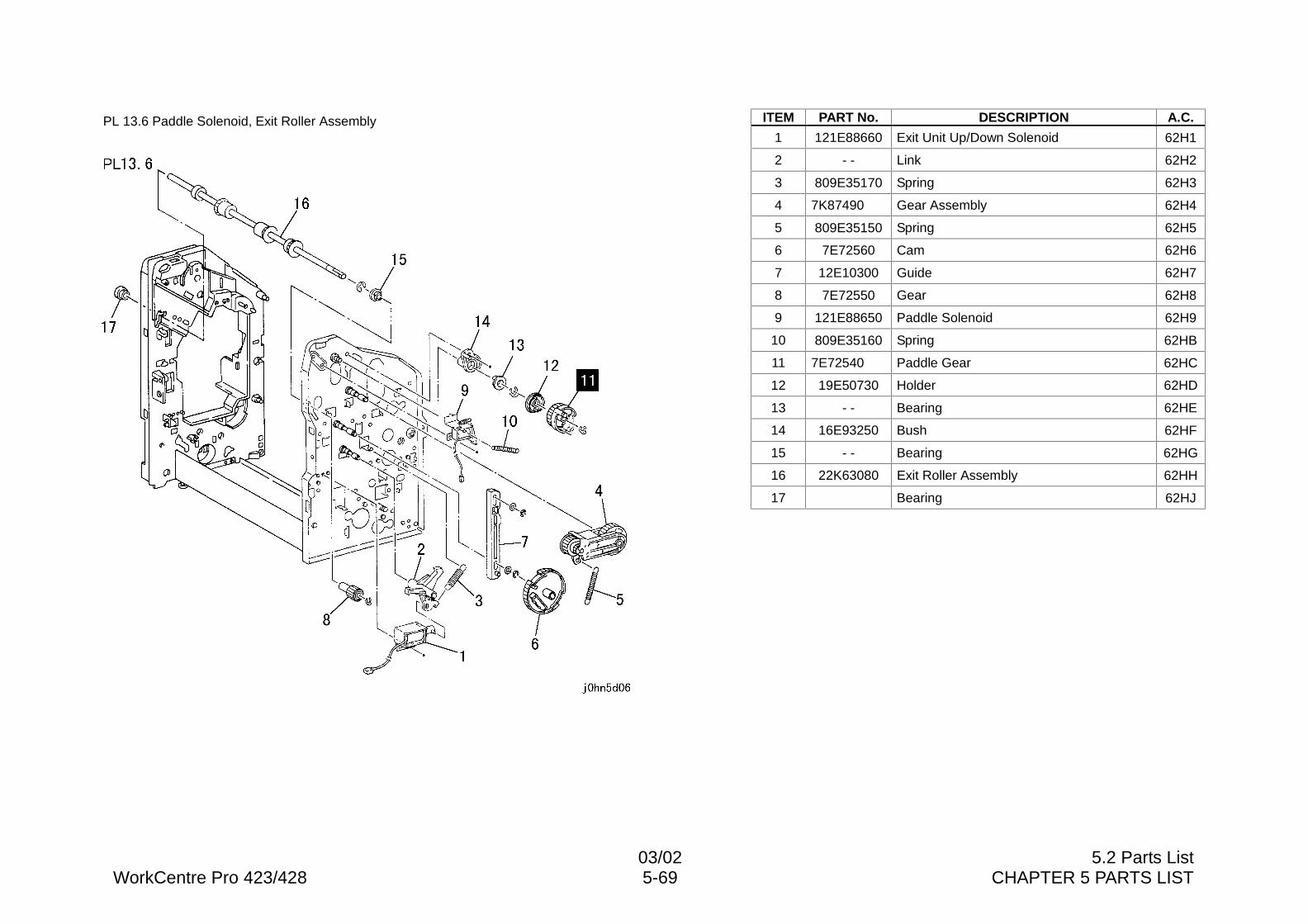
03/02 5.2 Parts ListWorkCentre Pro 423/428 5-69 CHAPTER 5 PARTS LIST
PL 13.6 Paddle Solenoid, Exit Roller Assembly ITEM PART No. DESCRIPTION A.C.
1 121E88660 Exit Unit Up/Down Solenoid 62H1
2 - - Link 62H2
3 809E35170 Spring 62H3
4 7K87490 Gear Assembly 62H4
5 809E35150 Spring 62H5
6 7E72560 Cam 62H6
7 12E10300 Guide 62H7
8 7E72550 Gear 62H8
9 121E88650 Paddle Solenoid 62H9
10 809E35160 Spring 62HB
11 7E72540 Paddle Gear 62HC
12 19E50730 Holder 62HD
13 - - Bearing 62HE
14 16E93250 Bush 62HF
15 - - Bearing 62HG
16 22K63080 Exit Roller Assembly 62HH
17 Bearing 62HJ
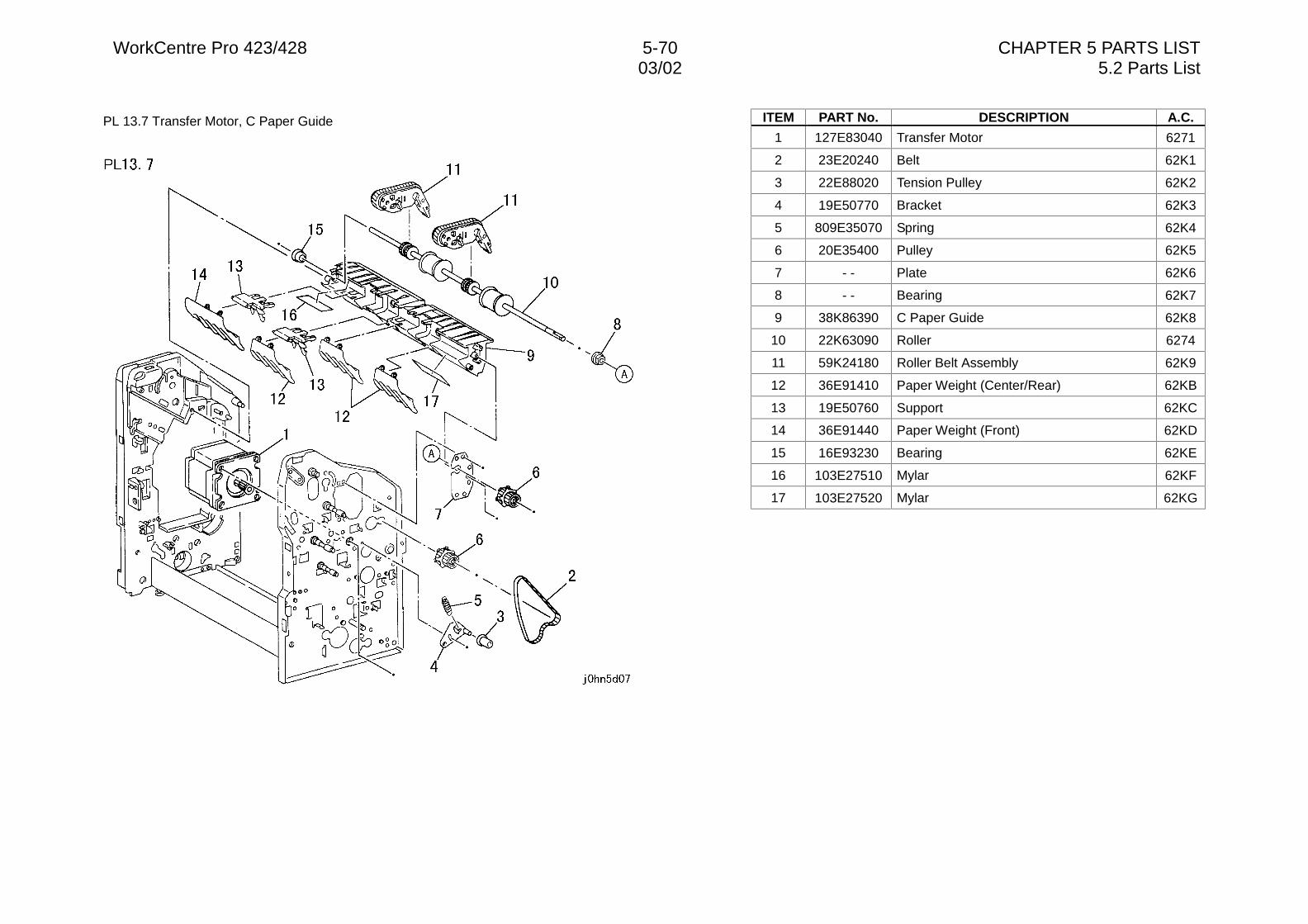
WorkCentre Pro 423/428 5-70 CHAPTER 5 PARTS LIST03/02 5.2 Parts List
PL 13.7 Transfer Motor, C Paper Guide ITEM PART No. DESCRIPTION A.C.
1 127E83040 Transfer Motor 6271
2 23E20240 Belt 62K1
3 22E88020 Tension Pulley 62K2
4 19E50770 Bracket 62K3
5 809E35070 Spring 62K4
6 20E35400 Pulley 62K5
7 - - Plate 62K6
8 - - Bearing 62K7
9 38K86390 C Paper Guide 62K8
10 22K63090 Roller 6274
11 59K24180 Roller Belt Assembly 62K9
12 36E91410 Paper Weight (Center/Rear) 62KB
13 19E50760 Support 62KC
14 36E91440 Paper Weight (Front) 62KD
15 16E93230 Bearing 62KE
16 103E27510 Mylar 62KF
17 103E27520 Mylar 62KG
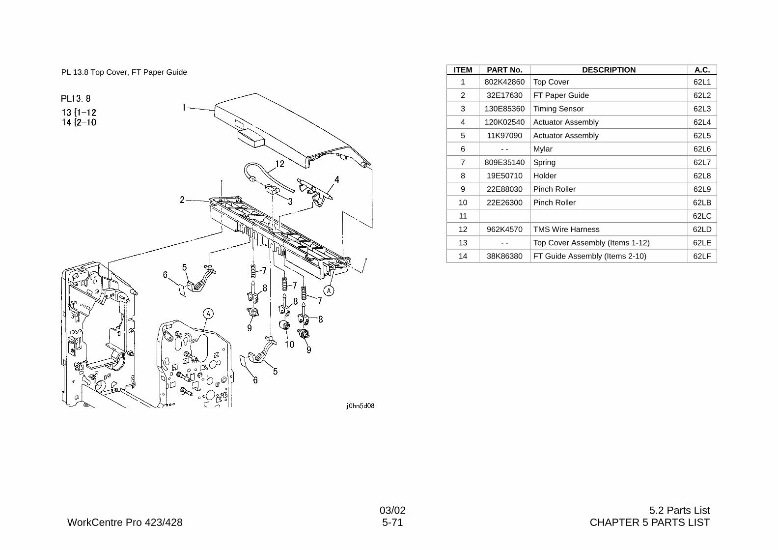
03/02 5.2 Parts ListWorkCentre Pro 423/428 5-71 CHAPTER 5 PARTS LIST
PL 13.8 Top Cover, FT Paper Guide ITEM PART No. DESCRIPTION A.C.
1 802K42860 Top Cover 62L1
2 32E17630 FT Paper Guide 62L2
3 130E85360 Timing Sensor 62L3
4 120K02540 Actuator Assembly 62L4
5 11K97090 Actuator Assembly 62L5
6 - - Mylar 62L6
7 809E35140 Spring 62L7
8 19E50710 Holder 62L8
9 22E88030 Pinch Roller 62L9
10 22E26300 Pinch Roller 62LB
11 62LC
12 962K4570 TMS Wire Harness 62LD
13 - - Top Cover Assembly (Items 1-12) 62LE
14 38K86380 FT Guide Assembly (Items 2-10) 62LF
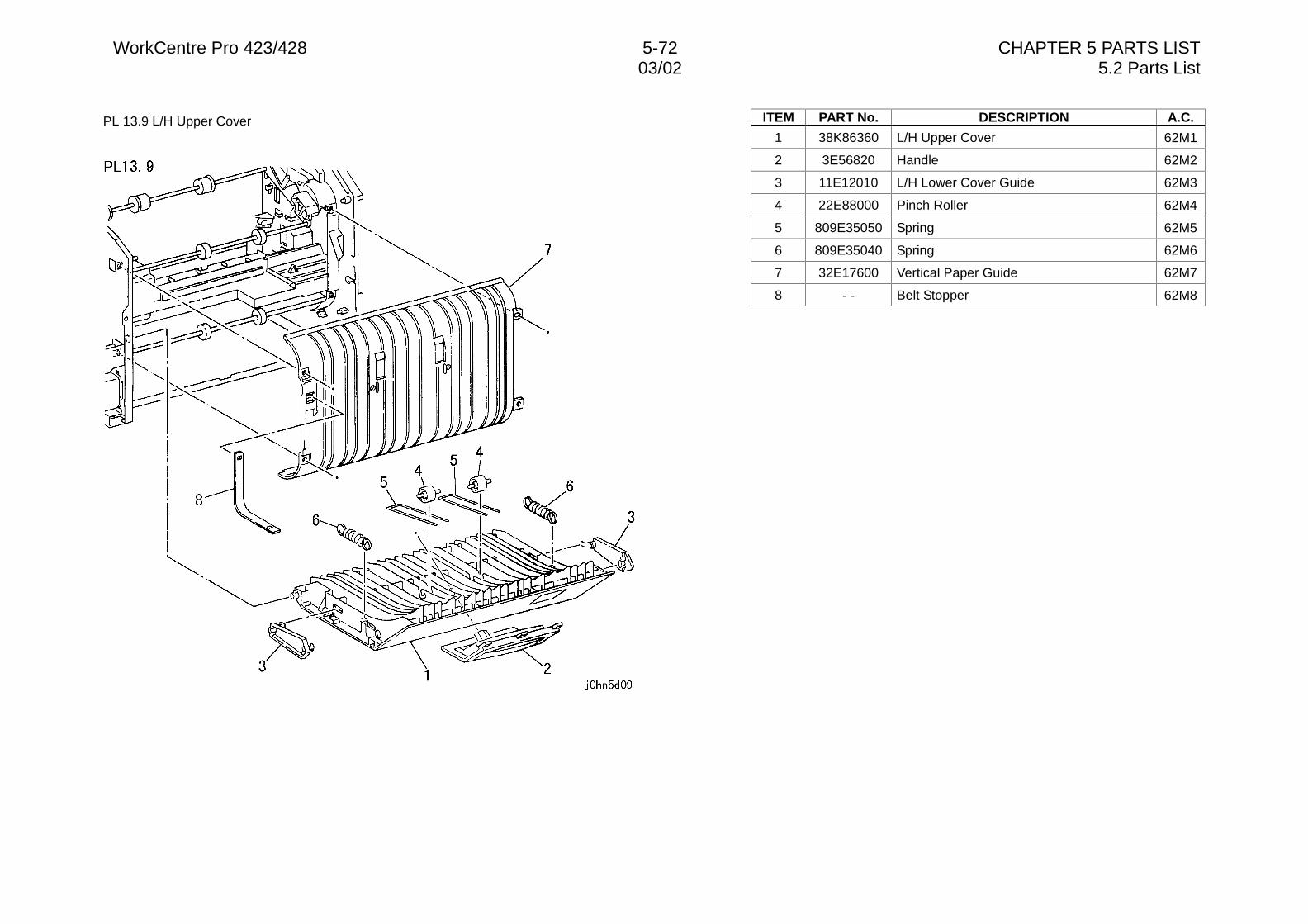
WorkCentre Pro 423/428 5-72 CHAPTER 5 PARTS LIST03/02 5.2 Parts List
PL 13.9 L/H Upper Cover ITEM PART No. DESCRIPTION A.C.
1 38K86360 L/H Upper Cover 62M1
2 3E56820 Handle 62M2
3 11E12010 L/H Lower Cover Guide 62M3
4 22E88000 Pinch Roller 62M4
5 809E35050 Spring 62M5
6 809E35040 Spring 62M6
7 32E17600 Vertical Paper Guide 62M7
8 - - Belt Stopper 62M8
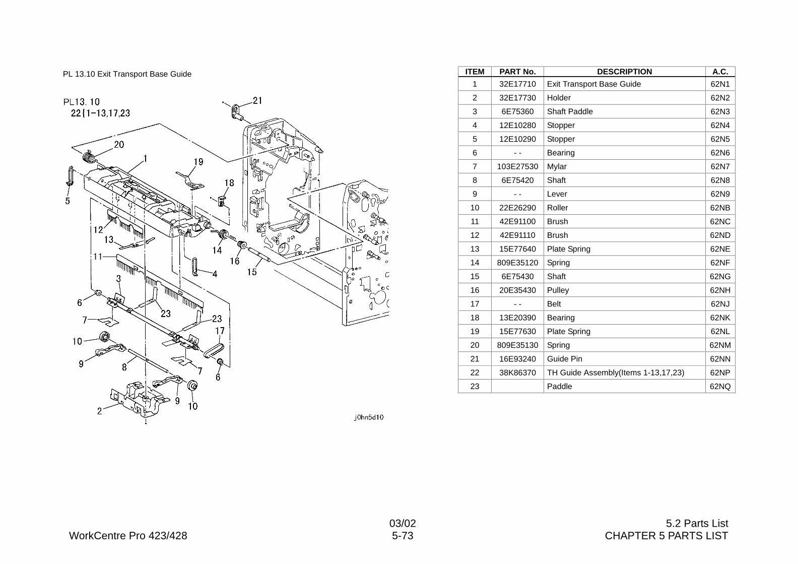
03/02 5.2 Parts ListWorkCentre Pro 423/428 5-73 CHAPTER 5 PARTS LIST
PL 13.10 Exit Transport Base Guide ITEM PART No. DESCRIPTION A.C.
1 32E17710 Exit Transport Base Guide 62N1
2 32E17730 Holder 62N2
3 6E75360 Shaft Paddle 62N3
4 12E10280 Stopper 62N4
5 12E10290 Stopper 62N5
6 - - Bearing 62N6
7 103E27530 Mylar 62N7
8 6E75420 Shaft 62N8
9 - - Lever 62N9
10 22E26290 Roller 62NB
11 42E91100 Brush 62NC
12 42E91110 Brush 62ND
13 15E77640 Plate Spring 62NE
14 809E35120 Spring 62NF
15 6E75430 Shaft 62NG
16 20E35430 Pulley 62NH
17 - - Belt 62NJ
18 13E20390 Bearing 62NK
19 15E77630 Plate Spring 62NL
20 809E35130 Spring 62NM
21 16E93240 Guide Pin 62NN
22 38K86370 TH Guide Assembly(Items 1-13,17,23) 62NP
23 Paddle 62NQ
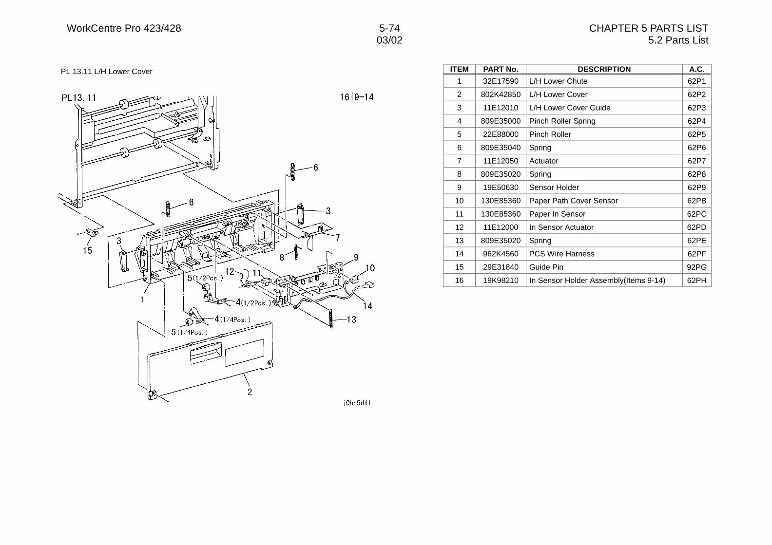
WorkCentre Pro 423/428 5-74 CHAPTER 5 PARTS LIST03/02 5.2 Parts List
PL 13.11 L/H Lower Cover ITEM PART No. DESCRIPTION A.C.
1 32E17590 L/H Lower Chute 62P1
2 802K42850 L/H Lower Cover 62P2
3 11E12010 L/H Lower Cover Guide 62P3
4 809E35000 Pinch Roller Spring 62P4
5 22E88000 Pinch Roller 62P5
6 809E35040 Spring 62P6
7 11E12050 Actuator 62P7
8 809E35020 Spring 62P8
9 19E50630 Sensor Holder 62P9
10 130E85360 Paper Path Cover Sensor 62PB
11 130E85360 Paper In Sensor 62PC
12 11E12000 In Sensor Actuator 62PD
13 809E35020 Spring 62PE
14 962K4560 PCS Wire Harness 62PF
15 29E31840 Guide Pin 92PG
16 19K98210 In Sensor Holder Assembly(Items 9-14) 62PH
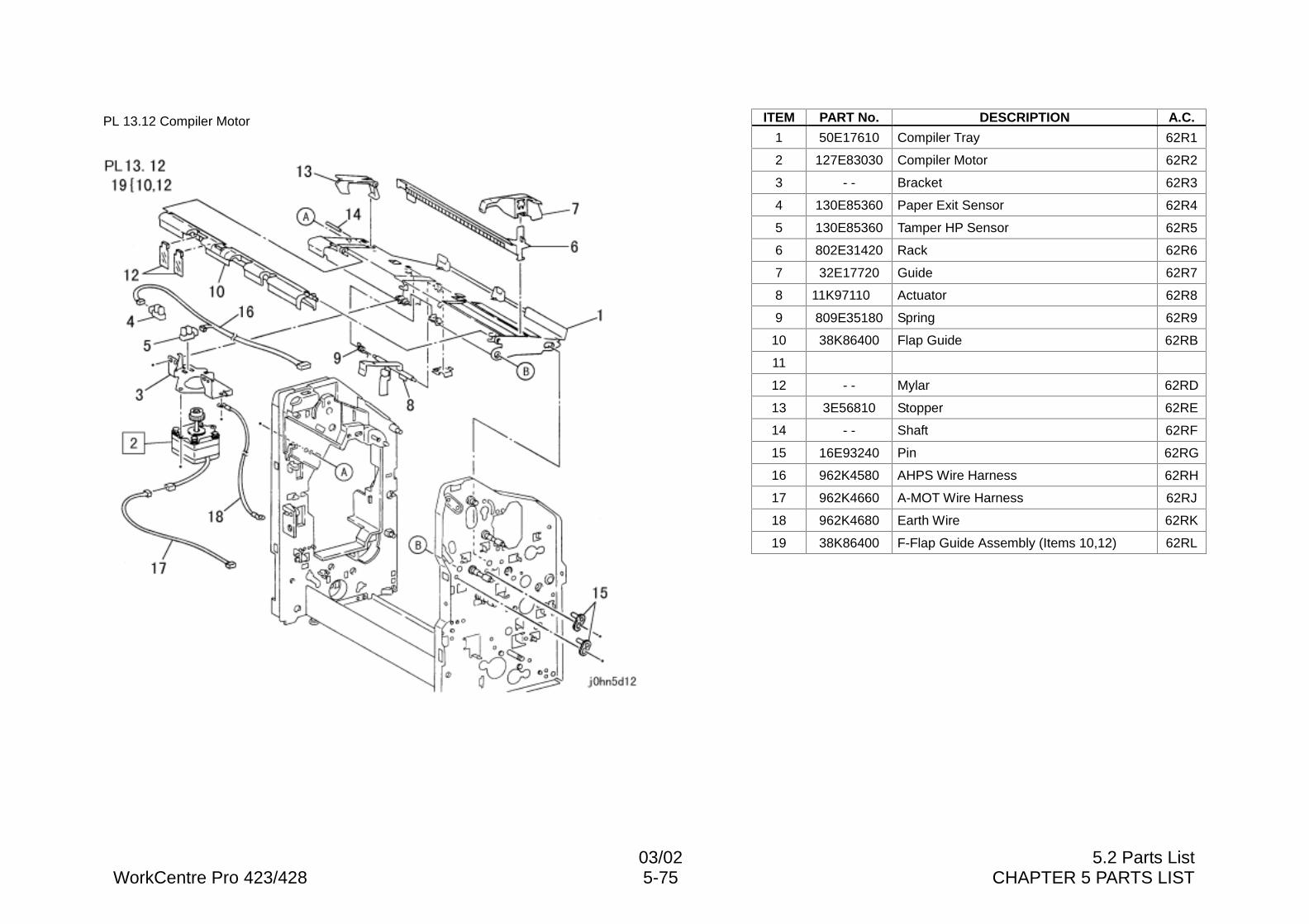
03/02 5.2 Parts ListWorkCentre Pro 423/428 5-75 CHAPTER 5 PARTS LIST
PL 13.12 Compiler Motor ITEM PART No. DESCRIPTION A.C.
1 50E17610 Compiler Tray 62R1
2 127E83030 Compiler Motor 62R2
3 - - Bracket 62R3
4 130E85360 Paper Exit Sensor 62R4
5 130E85360 Tamper HP Sensor 62R5
6 802E31420 Rack 62R6
7 32E17720 Guide 62R7
8 11K97110 Actuator 62R8
9 809E35180 Spring 62R9
10 38K86400 Flap Guide 62RB
11
12 - - Mylar 62RD
13 3E56810 Stopper 62RE
14 - - Shaft 62RF
15 16E93240 Pin 62RG
16 962K4580 AHPS Wire Harness 62RH
17 962K4660 A-MOT Wire Harness 62RJ
18 962K4680 Earth Wire 62RK
19 38K86400 F-Flap Guide Assembly (Items 10,12) 62RL
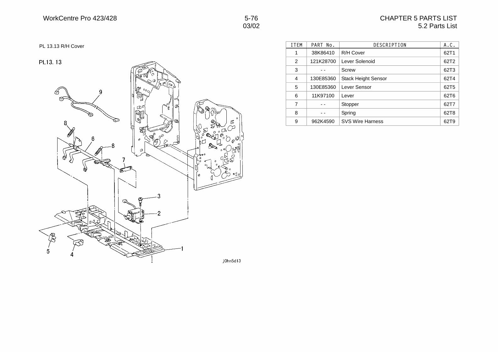
WorkCentre Pro 423/428 5-76 CHAPTER 5 PARTS LIST03/02 5.2 Parts List
PL 13.13 R/H Cover ,7(0 3$57�1R� '(6&5,37,21 $�&�
1 38K86410 R/H Cover 62T1
2 121K28700 Lever Solenoid 62T2
3 - - Screw 62T3
4 130E85360 Stack Height Sensor 62T4
5 130E85360 Lever Sensor 62T5
6 11K97100 Lever 62T6
7 - - Stopper 62T7
8 - - Spring 62T8
9 962K4590 SVS Wire Harness 62T9
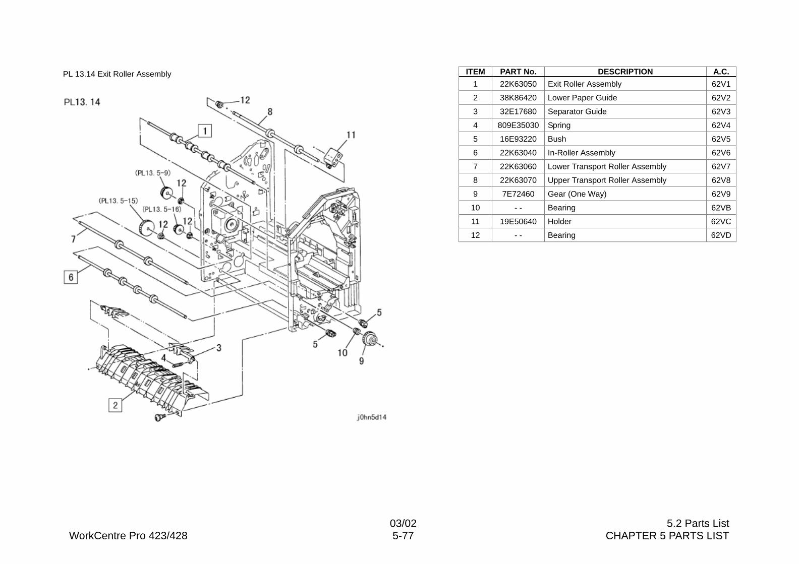
03/02 5.2 Parts ListWorkCentre Pro 423/428 5-77 CHAPTER 5 PARTS LIST
PL 13.14 Exit Roller Assembly ITEM PART No. DESCRIPTION A.C.
1 22K63050 Exit Roller Assembly 62V1
2 38K86420 Lower Paper Guide 62V2
3 32E17680 Separator Guide 62V3
4 809E35030 Spring 62V4
5 16E93220 Bush 62V5
6 22K63040 In-Roller Assembly 62V6
7 22K63060 Lower Transport Roller Assembly 62V7
8 22K63070 Upper Transport Roller Assembly 62V8
9 7E72460 Gear (One Way) 62V9
10 - - Bearing 62VB
11 19E50640 Holder 62VC
12 - - Bearing 62VD
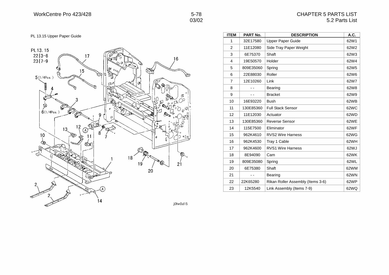
WorkCentre Pro 423/428 5-78 CHAPTER 5 PARTS LIST03/02 5.2 Parts List
PL 13.15 Upper Paper Guide ITEM PART No. DESCRIPTION A.C.
1 32E17580 Upper Paper Guide 62W1
2 11E12080 Side Tray Paper Weight 62W2
3 6E75370 Shaft 62W3
4 19E50570 Holder 62W4
5 809E35060 Spring 62W5
6 22E88030 Roller 62W6
7 12E10260 Link 62W7
8 - - Bearing 62W8
9 - - Bracket 62W9
10 16E93220 Bush 62WB
11 130E85360 Full Stack Sensor 62WC
12 11E12030 Actuator 62WD
13 130E85360 Reverse Sensor 62WE
14 115E7500 Eliminator 62WF
15 962K4610 RVS2 Wire Harness 62WG
16 962K4530 Tray 1 Cable 62WH
17 962K4600 RVS1 Wire Harness 62WJ
18 8E94090 Cam 62WK
19 809E35080 Spring 62WL
20 6E75380 Shaft 62WM
21 - - Bearing 62WN
22 22K65280 Rikan Roller Assembly (Items 3-6) 62WP
23 12K5540 Link Assembly (Items 7-9) 62WQ
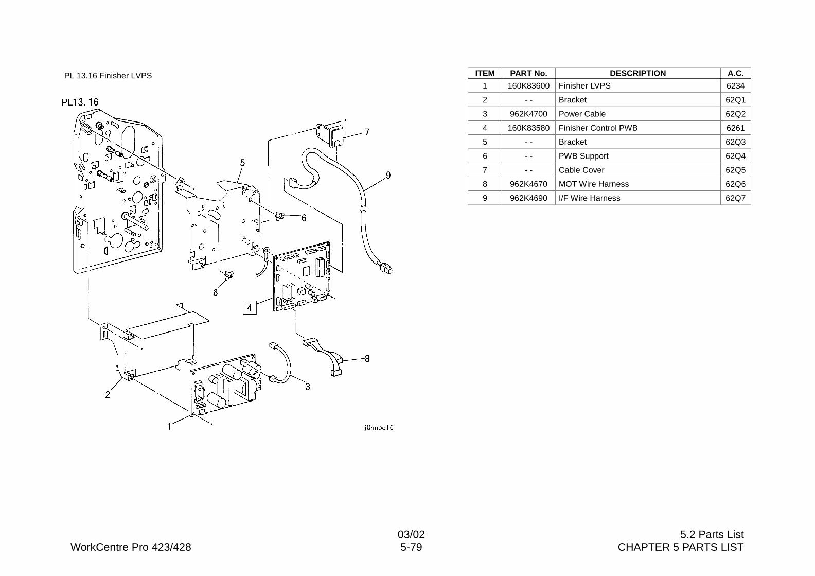
03/02 5.2 Parts ListWorkCentre Pro 423/428 5-79 CHAPTER 5 PARTS LIST
PL 13.16 Finisher LVPS ITEM PART No. DESCRIPTION A.C.
1 160K83600 Finisher LVPS 6234
2 - - Bracket 62Q1
3 962K4700 Power Cable 62Q2
4 160K83580 Finisher Control PWB 6261
5 - - Bracket 62Q3
6 - - PWB Support 62Q4
7 - - Cable Cover 62Q5
8 962K4670 MOT Wire Harness 62Q6
9 962K4690 I/F Wire Harness 62Q7
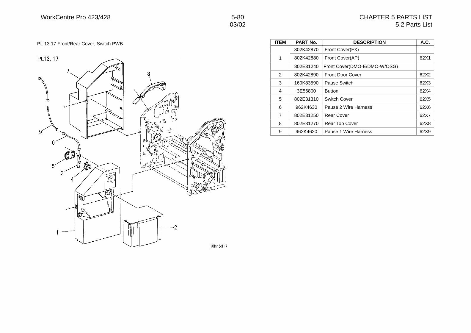
WorkCentre Pro 423/428 5-80 CHAPTER 5 PARTS LIST03/02 5.2 Parts List
PL 13.17 Front/Rear Cover, Switch PWB ITEM PART No. DESCRIPTION A.C.
802K42870 Front Cover(FX)
802K42880 Front Cover(AP) 62X11
802E31240 Front Cover(DMO-E/DMO-W/OSG)
2 802K42890 Front Door Cover 62X2
3 160K83590 Pause Switch 62X3
4 3E56800 Button 62X4
5 802E31310 Switch Cover 62X5
6 962K4630 Pause 2 Wire Harness 62X6
7 802E31250 Rear Cover 62X7
8 802E31270 Rear Top Cover 62X8
9 962K4620 Pause 1 Wire Harness 62X9
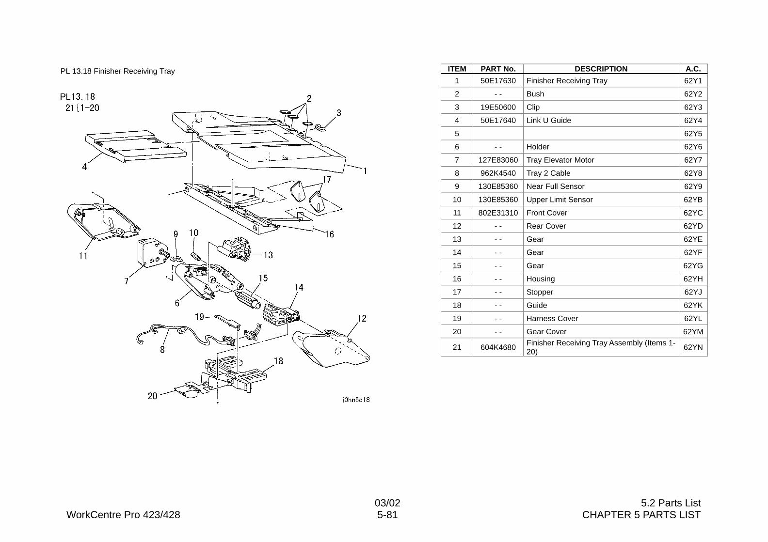
03/02 5.2 Parts ListWorkCentre Pro 423/428 5-81 CHAPTER 5 PARTS LIST
PL 13.18 Finisher Receiving Tray ITEM PART No. DESCRIPTION A.C.
1 50E17630 Finisher Receiving Tray 62Y1
2 - - Bush 62Y2
3 19E50600 Clip 62Y3
4 50E17640 Link U Guide 62Y4
5 62Y5
6 - - Holder 62Y6
7 127E83060 Tray Elevator Motor 62Y7
8 962K4540 Tray 2 Cable 62Y8
9 130E85360 Near Full Sensor 62Y9
10 130E85360 Upper Limit Sensor 62YB
11 802E31310 Front Cover 62YC
12 - - Rear Cover 62YD
13 - - Gear 62YE
14 - - Gear 62YF
15 - - Gear 62YG
16 - - Housing 62YH
17 - - Stopper 62YJ
18 - - Guide 62YK
19 - - Harness Cover 62YL
20 - - Gear Cover 62YM
21 604K4680Finisher Receiving Tray Assembly (Items 1-20) 62YN
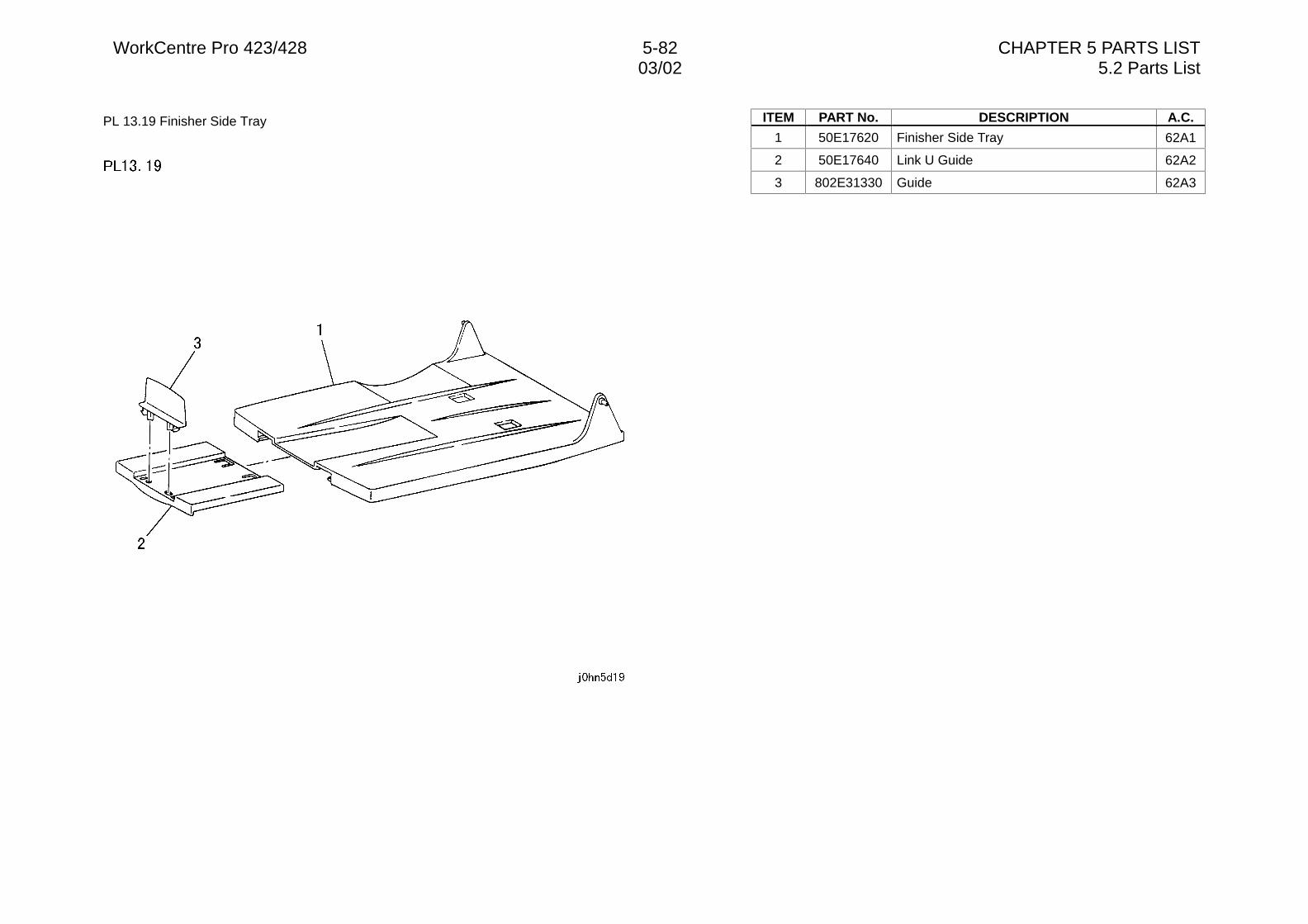
WorkCentre Pro 423/428 5-82 CHAPTER 5 PARTS LIST03/02 5.2 Parts List
PL 13.19 Finisher Side Tray ITEM PART No. DESCRIPTION A.C.
1 50E17620 Finisher Side Tray 62A1
2 50E17640 Link U Guide 62A2
3 802E31330 Guide 62A3
03/02 5.2 Parts ListWorkCentre Pro 423/428 5-83 CHAPTER 5 PARTS LIST
PL 14.1 Consumables and Special Tools ITEM PART No. DESCRIPTION A.C.
1 499T247 A3 Test Pattern
2 499T281 A4 Fax Test Pattern
3 70E90000 Lubricant
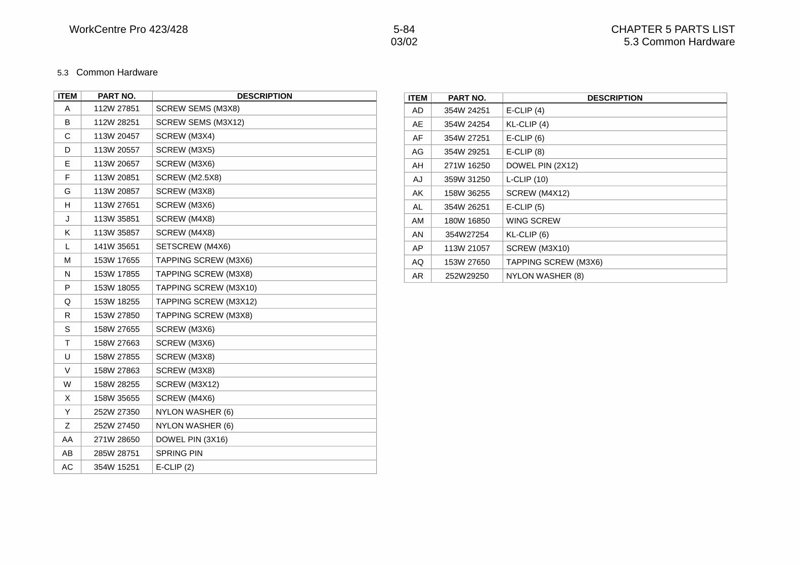
WorkCentre Pro 423/428 5-84 CHAPTER 5 PARTS LIST03/02 5.3 Common Hardware
5.3 Common Hardware
ITEM PART NO. DESCRIPTION
A 112W 27851 SCREW SEMS (M3X8)
B 112W 28251 SCREW SEMS (M3X12)
C 113W 20457 SCREW (M3X4)
D 113W 20557 SCREW (M3X5)
E 113W 20657 SCREW (M3X6)
F 113W 20851 SCREW (M2.5X8)
G 113W 20857 SCREW (M3X8)
H 113W 27651 SCREW (M3X6)
J 113W 35851 SCREW (M4X8)
K 113W 35857 SCREW (M4X8)
L 141W 35651 SETSCREW (M4X6)
M 153W 17655 TAPPING SCREW (M3X6)
N 153W 17855 TAPPING SCREW (M3X8)
P 153W 18055 TAPPING SCREW (M3X10)
Q 153W 18255 TAPPING SCREW (M3X12)
R 153W 27850 TAPPING SCREW (M3X8)
S 158W 27655 SCREW (M3X6)
T 158W 27663 SCREW (M3X6)
U 158W 27855 SCREW (M3X8)
V 158W 27863 SCREW (M3X8)
W 158W 28255 SCREW (M3X12)
X 158W 35655 SCREW (M4X6)
Y 252W 27350 NYLON WASHER (6)
Z 252W 27450 NYLON WASHER (6)
AA 271W 28650 DOWEL PIN (3X16)
AB 285W 28751 SPRING PIN
AC 354W 15251 E-CLIP (2)
ITEM PART NO. DESCRIPTION
AD 354W 24251 E-CLIP (4)
AE 354W 24254 KL-CLIP (4)
AF 354W 27251 E-CLIP (6)
AG 354W 29251 E-CLIP (8)
AH 271W 16250 DOWEL PIN (2X12)
AJ 359W 31250 L-CLIP (10)
AK 158W 36255 SCREW (M4X12)
AL 354W 26251 E-CLIP (5)
AM 180W 16850 WING SCREW
AN 354W27254 KL-CLIP (6)
AP 113W 21057 SCREW (M3X10)
AQ 153W 27650 TAPPING SCREW (M3X6)
AR 252W29250 NYLON WASHER (8)

03/02 5.2 Parts ListWorkCentre Pro 423/428 5-85 CHAPTER 5 PARTS LIST

CHAPTER 6 GENERAL

03/02 ContentsWorkCentre Pro 423/428 6-1 CHAPTER 6 GENERAL
Contents6.1 Specifications ...............................................................................................2
6.1.1 Product Name/Prod. Code/Model Code/Serial No. .................................26.1.2 Machine Size/Weight/Space Requirement ..............................................36.1.3 Copy Features ........................................................................................56.1.4 Fax Features...........................................................................................76.1.5 Direct FAX Specification/Functions .........................................................86.1.6 Printer feature .........................................................................................96.1.7 System feature – Memory.....................................................................106.1.8 Electrical feature ...................................................................................106.1.9 Input area features................................................................................116.1.10 DADF Specification ............................................................................126.1.11 Scanner specifications/functions ........................................................126.1.12 Output area feature............................................................................136.1.13 Stapler Finisher (Option) Specification ...............................................136.1.14 Environmental requirement ................................................................136.1.15 Optional specifications .......................................................................14
6.2 Tools and Service Consumables.................................................................14
6.2.1 Tools .....................................................................................................146.2.2 Service Consumables ...........................................................................14
6.3 Consumables .............................................................................................14
6.4 Modification ................................................................................................15
6.4.1 Symbology............................................................................................156.4.2 Modification List ....................................................................................15
6.5 Installation ..................................................................................................17
6.6 Removal .....................................................................................................24
6.7 Custom Presets ..........................................................................................25
6.7.1 Custom Presets Chain-Function Code List ...........................................256.7.2 How to change Custom Presets in User mode......................................28
6.8 General Information....................................................................................29
6.8.1 Forced polling of documents stored in memory.....................................296.8.2 How to By-pass the IOT Password Protection.......................................296.8.3 Location of Serial Number Plate ...........................................................296.8.4 How to Read Emergency History ..........................................................306.8.5 Copy features list ..................................................................................316.8.6 Fax features list ....................................................................................31
6.9 Function Flow (Function Tree) ....................................................................34
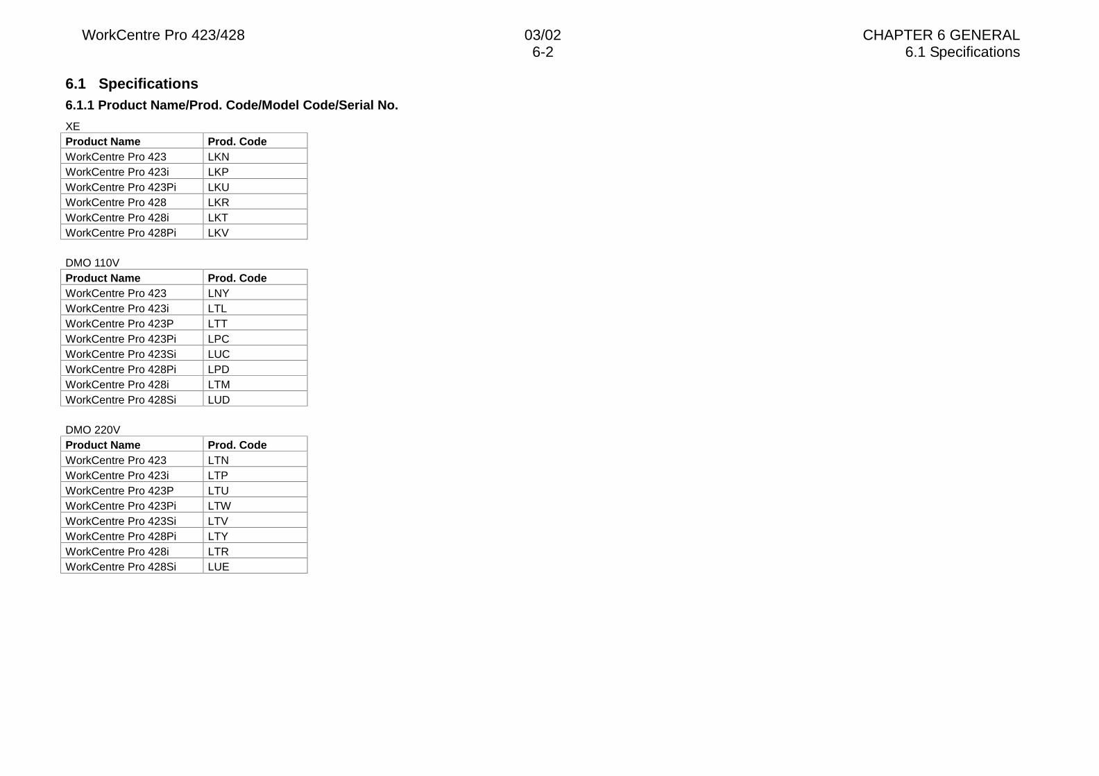
WorkCentre Pro 423/428 03/02 CHAPTER 6 GENERAL6-2 6.1 Specifications
6.1 Specifications6.1.1 Product Name/Prod. Code/Model Code/Serial No.
XEProduct Name Prod. CodeWorkCentre Pro 423 LKNWorkCentre Pro 423i LKPWorkCentre Pro 423Pi LKUWorkCentre Pro 428 LKRWorkCentre Pro 428i LKTWorkCentre Pro 428Pi LKV
DMO 110VProduct Name Prod. CodeWorkCentre Pro 423 LNYWorkCentre Pro 423i LTLWorkCentre Pro 423P LTTWorkCentre Pro 423Pi LPCWorkCentre Pro 423Si LUCWorkCentre Pro 428Pi LPDWorkCentre Pro 428i LTMWorkCentre Pro 428Si LUD
DMO 220VProduct Name Prod. CodeWorkCentre Pro 423 LTNWorkCentre Pro 423i LTPWorkCentre Pro 423P LTUWorkCentre Pro 423Pi LTWWorkCentre Pro 423Si LTVWorkCentre Pro 428Pi LTYWorkCentre Pro 428i LTRWorkCentre Pro 428Si LUE
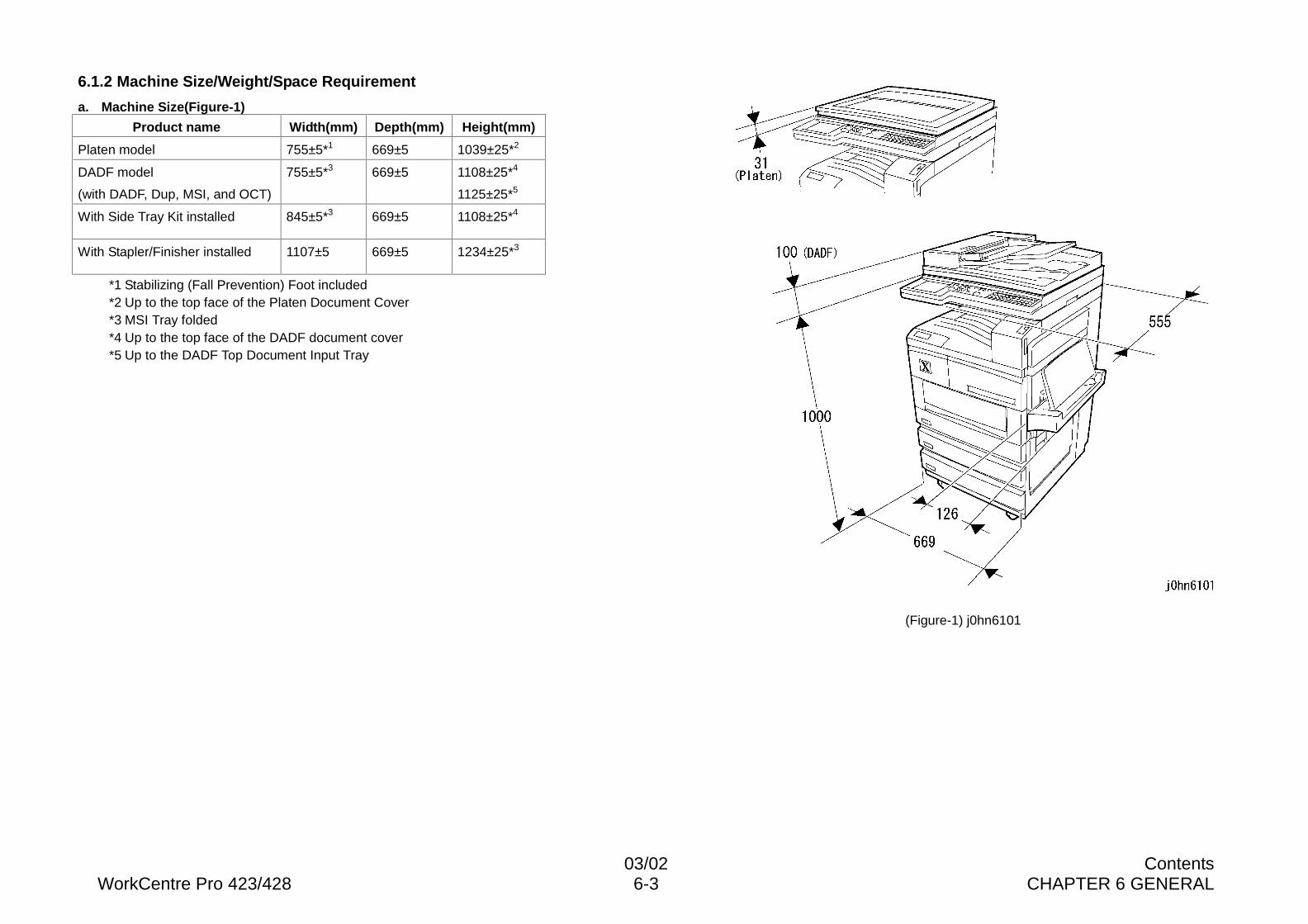
03/02 ContentsWorkCentre Pro 423/428 6-3 CHAPTER 6 GENERAL
6.1.2 Machine Size/Weight/Space Requirement
a. Machine Size(Figure-1)
Product name Width(mm) Depth(mm) Height(mm)
Platen model 755±5*1 669±5 1039±25*2
DADF model
(with DADF, Dup, MSI, and OCT)
755±5*3 669±5 1108±25*4
1125±25*5
With Side Tray Kit installed 845±5*3 669±5 1108±25*4
With Stapler/Finisher installed 1107±5 669±5 1234±25*3
*1 Stabilizing (Fall Prevention) Foot included*2 Up to the top face of the Platen Document Cover*3 MSI Tray folded*4 Up to the top face of the DADF document cover*5 Up to the DADF Top Document Input Tray
(Figure-1) j0hn6101
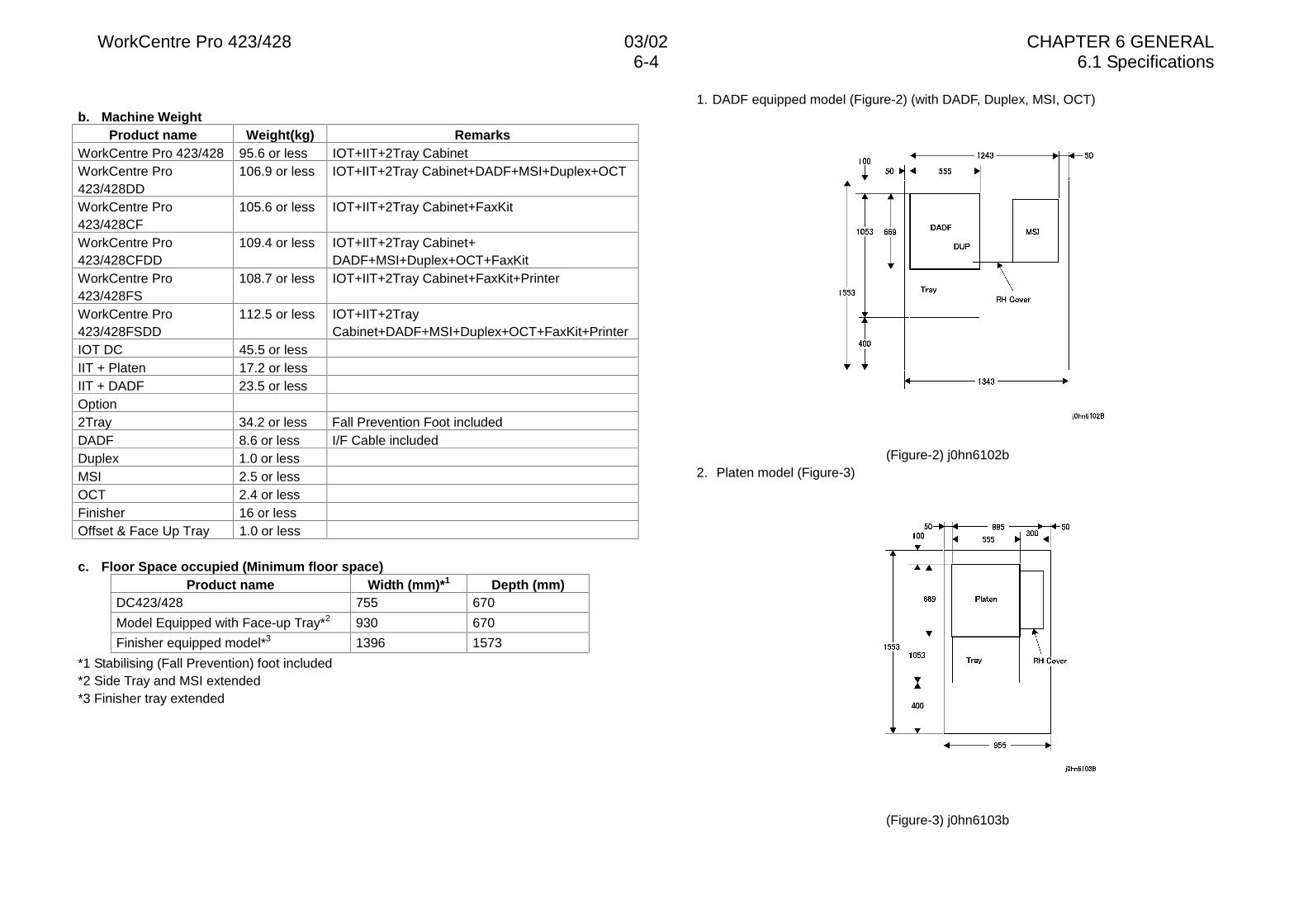
WorkCentre Pro 423/428 03/02 CHAPTER 6 GENERAL6-4 6.1 Specifications
b. Machine WeightProduct name Weight(kg) Remarks
WorkCentre Pro 423/428 95.6 or less IOT+IIT+2Tray CabinetWorkCentre Pro423/428DD
106.9 or less IOT+IIT+2Tray Cabinet+DADF+MSI+Duplex+OCT
WorkCentre Pro423/428CF
105.6 or less IOT+IIT+2Tray Cabinet+FaxKit
WorkCentre Pro423/428CFDD
109.4 or less IOT+IIT+2Tray Cabinet+DADF+MSI+Duplex+OCT+FaxKit
WorkCentre Pro423/428FS
108.7 or less IOT+IIT+2Tray Cabinet+FaxKit+Printer
WorkCentre Pro423/428FSDD
112.5 or less IOT+IIT+2TrayCabinet+DADF+MSI+Duplex+OCT+FaxKit+Printer
IOT DC 45.5 or lessIIT + Platen 17.2 or lessIIT + DADF 23.5 or lessOption2Tray 34.2 or less Fall Prevention Foot includedDADF 8.6 or less I/F Cable includedDuplex 1.0 or lessMSI 2.5 or lessOCT 2.4 or lessFinisher 16 or lessOffset & Face Up Tray 1.0 or less
c. Floor Space occupied (Minimum floor space)Product name Width (mm)*1 Depth (mm)
DC423/428 755 670
Model Equipped with Face-up Tray*2 930 670
Finisher equipped model*3 1396 1573
*1 Stabilising (Fall Prevention) foot included*2 Side Tray and MSI extended*3 Finisher tray extended
1. DADF equipped model (Figure-2) (with DADF, Duplex, MSI, OCT)
(Figure-2) j0hn6102b2. Platen model (Figure-3)
(Figure-3) j0hn6103b
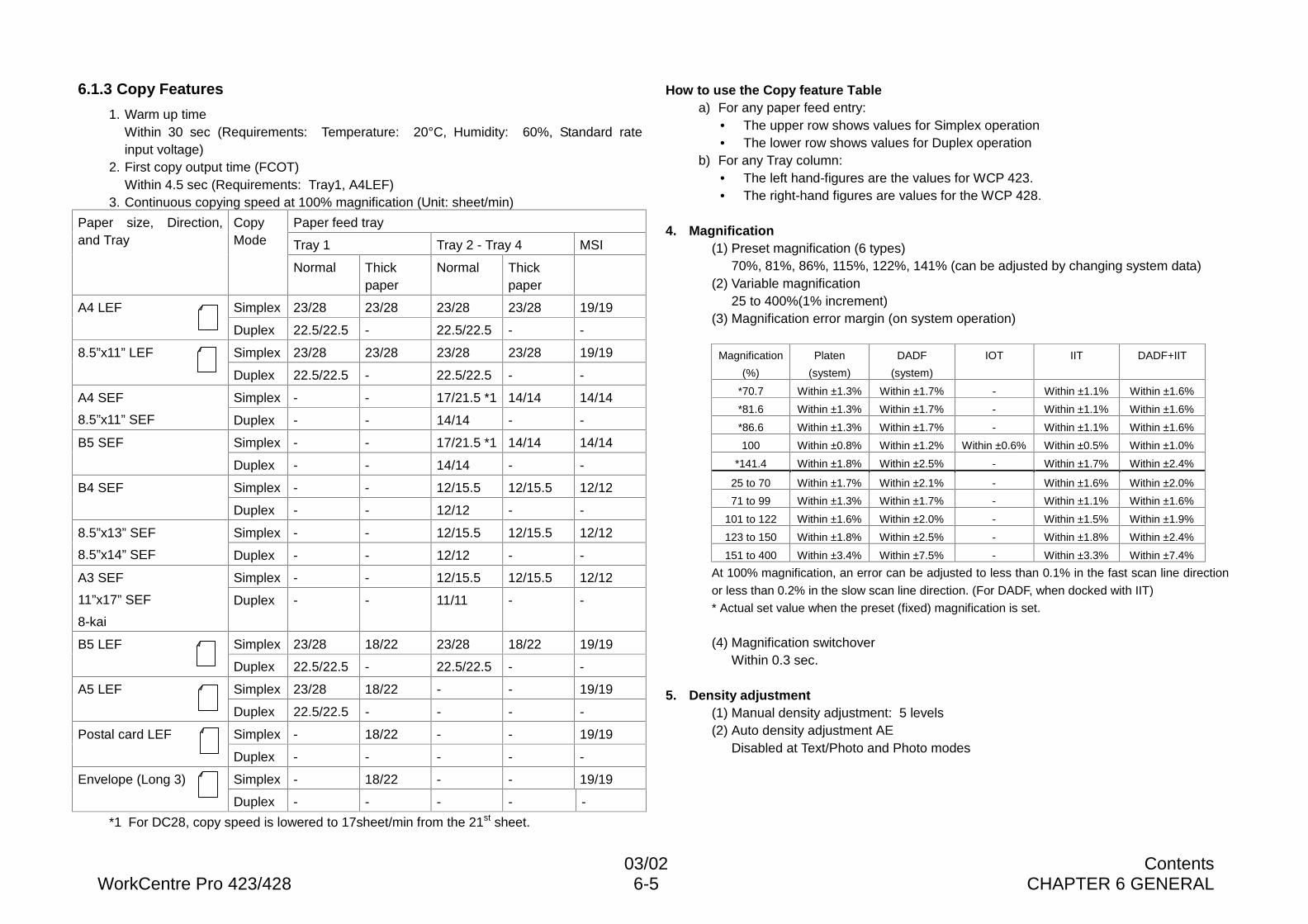
03/02 ContentsWorkCentre Pro 423/428 6-5 CHAPTER 6 GENERAL
6.1.3 Copy Features
1. Warm up timeWithin 30 sec (Requirements: Temperature: 20°C, Humidity: 60%, Standard rateinput voltage)
2. First copy output time (FCOT)Within 4.5 sec (Requirements: Tray1, A4LEF)
3. Continuous copying speed at 100% magnification (Unit: sheet/min)
Paper feed tray
Tray 1 Tray 2 - Tray 4 MSI
Paper size, Direction,and Tray
CopyMode
Normal Thickpaper
Normal Thickpaper
Simplex 23/28 23/28 23/28 23/28 19/19A4 LEF
Duplex 22.5/22.5 - 22.5/22.5 - -
Simplex 23/28 23/28 23/28 23/28 19/198.5”x11” LEF
Duplex 22.5/22.5 - 22.5/22.5 - -
Simplex - - 17/21.5 *1 14/14 14/14A4 SEF
8.5”x11” SEF Duplex - - 14/14 - -
Simplex - - 17/21.5 *1 14/14 14/14B5 SEF
Duplex - - 14/14 - -
Simplex - - 12/15.5 12/15.5 12/12B4 SEF
Duplex - - 12/12 - -
Simplex - - 12/15.5 12/15.5 12/128.5”x13” SEF
8.5”x14” SEF Duplex - - 12/12 - -
Simplex - - 12/15.5 12/15.5 12/12A3 SEF
11”x17” SEF
8-kai
Duplex - - 11/11 - -
Simplex 23/28 18/22 23/28 18/22 19/19B5 LEF
Duplex 22.5/22.5 - 22.5/22.5 - -
Simplex 23/28 18/22 - - 19/19A5 LEF
Duplex 22.5/22.5 - - - -
Simplex - 18/22 - - 19/19Postal card LEF
Duplex - - - - -
Simplex - 18/22 - - 19/19Envelope (Long 3)
Duplex - - - - -
*1 For DC28, copy speed is lowered to 17sheet/min from the 21st sheet.
How to use the Copy feature Tablea) For any paper feed entry:
• The upper row shows values for Simplex operation• The lower row shows values for Duplex operation
b) For any Tray column:• The left hand-figures are the values for WCP 423.• The right-hand figures are values for the WCP 428.
4. Magnification(1) Preset magnification (6 types)
70%, 81%, 86%, 115%, 122%, 141% (can be adjusted by changing system data)(2) Variable magnification
25 to 400%(1% increment)(3) Magnification error margin (on system operation)
Magnification
(%)
Platen
(system)
DADF
(system)
IOT IIT DADF+IIT
*70.7 Within ±1.3% Within ±1.7% - Within ±1.1% Within ±1.6%
*81.6 Within ±1.3% Within ±1.7% - Within ±1.1% Within ±1.6%
*86.6 Within ±1.3% Within ±1.7% - Within ±1.1% Within ±1.6%
100 Within ±0.8% Within ±1.2% Within ±0.6% Within ±0.5% Within ±1.0%
*141.4 Within ±1.8% Within ±2.5% - Within ±1.7% Within ±2.4%
25 to 70 Within ±1.7% Within ±2.1% - Within ±1.6% Within ±2.0%
71 to 99 Within ±1.3% Within ±1.7% - Within ±1.1% Within ±1.6%
101 to 122 Within ±1.6% Within ±2.0% - Within ±1.5% Within ±1.9%
123 to 150 Within ±1.8% Within ±2.5% - Within ±1.8% Within ±2.4%
151 to 400 Within ±3.4% Within ±7.5% - Within ±3.3% Within ±7.4%
At 100% magnification, an error can be adjusted to less than 0.1% in the fast scan line direction
or less than 0.2% in the slow scan line direction. (For DADF, when docked with IIT)
* Actual set value when the preset (fixed) magnification is set.
(4) Magnification switchoverWithin 0.3 sec.
5. Density adjustment(1) Manual density adjustment: 5 levels(2) Auto density adjustment AE
Disabled at Text/Photo and Photo modes
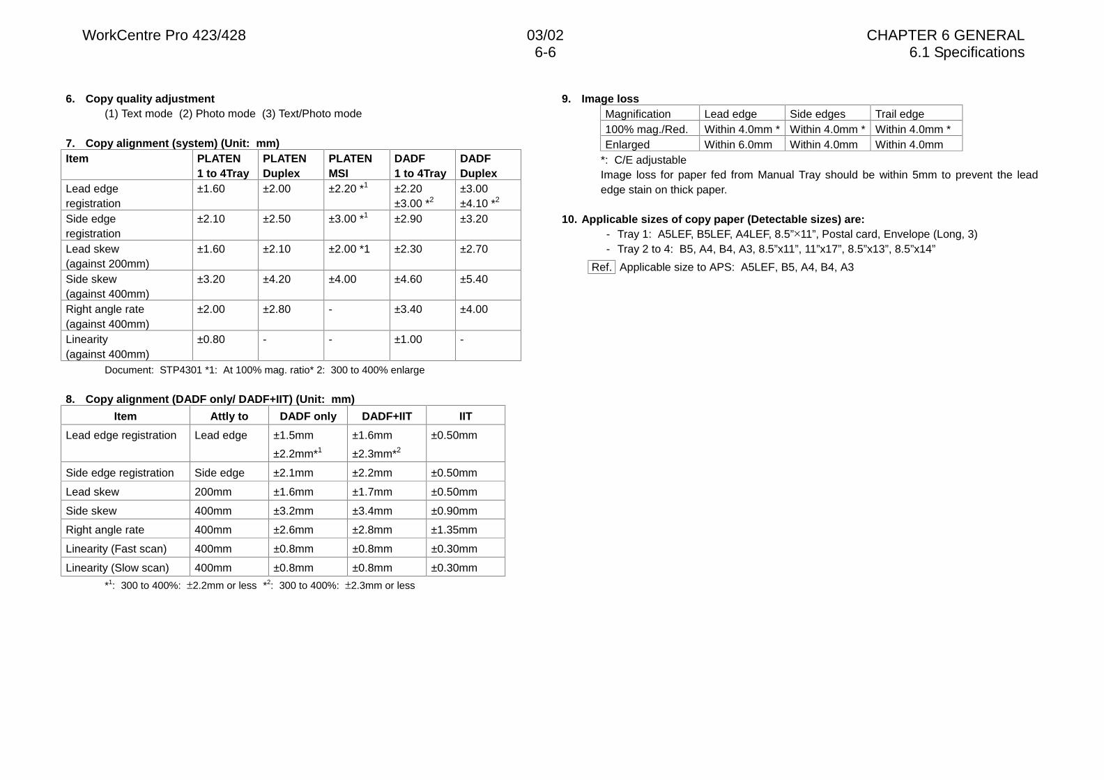
WorkCentre Pro 423/428 03/02 CHAPTER 6 GENERAL6-6 6.1 Specifications
6. Copy quality adjustment(1) Text mode (2) Photo mode (3) Text/Photo mode
7. Copy alignment (system) (Unit: mm)Item PLATEN
1 to 4TrayPLATENDuplex
PLATENMSI
DADF1 to 4Tray
DADFDuplex
Lead edgeregistration
±1.60 ±2.00 ±2.20 *1 ±2.20±3.00 *2
±3.00±4.10 *2
Side edgeregistration
±2.10 ±2.50 ±3.00 *1 ±2.90 ±3.20
Lead skew(against 200mm)
±1.60 ±2.10 ±2.00 *1 ±2.30 ±2.70
Side skew(against 400mm)
±3.20 ±4.20 ±4.00 ±4.60 ±5.40
Right angle rate(against 400mm)
±2.00 ±2.80 - ±3.40 ±4.00
Linearity(against 400mm)
±0.80 - - ±1.00 -
Document: STP4301 *1: At 100% mag. ratio* 2: 300 to 400% enlarge
8. Copy alignment (DADF only/ DADF+IIT) (Unit: mm)
Item Attly to DADF only DADF+IIT IIT
Lead edge registration Lead edge ±1.5mm
±2.2mm*1
±1.6mm
±2.3mm*2
±0.50mm
Side edge registration Side edge ±2.1mm ±2.2mm ±0.50mm
Lead skew 200mm ±1.6mm ±1.7mm ±0.50mm
Side skew 400mm ±3.2mm ±3.4mm ±0.90mm
Right angle rate 400mm ±2.6mm ±2.8mm ±1.35mm
Linearity (Fast scan) 400mm ±0.8mm ±0.8mm ±0.30mm
Linearity (Slow scan) 400mm ±0.8mm ±0.8mm ±0.30mm
*1: 300 to 400%: �2.2mm or less *2: 300 to 400%: �2.3mm or less
9. Image lossMagnification Lead edge Side edges Trail edge100% mag./Red. Within 4.0mm * Within 4.0mm * Within 4.0mm *Enlarged Within 6.0mm Within 4.0mm Within 4.0mm
*: C/E adjustableImage loss for paper fed from Manual Tray should be within 5mm to prevent the leadedge stain on thick paper.
10. Applicable sizes of copy paper (Detectable sizes) are:- Tray 1: A5LEF, B5LEF, A4LEF, 8.5”ò11”, Postal card, Envelope (Long, 3)- Tray 2 to 4: B5, A4, B4, A3, 8.5”x11”, 11”x17”, 8.5”x13”, 8.5”x14”
Ref. Applicable size to APS: A5LEF, B5, A4, B4, A3
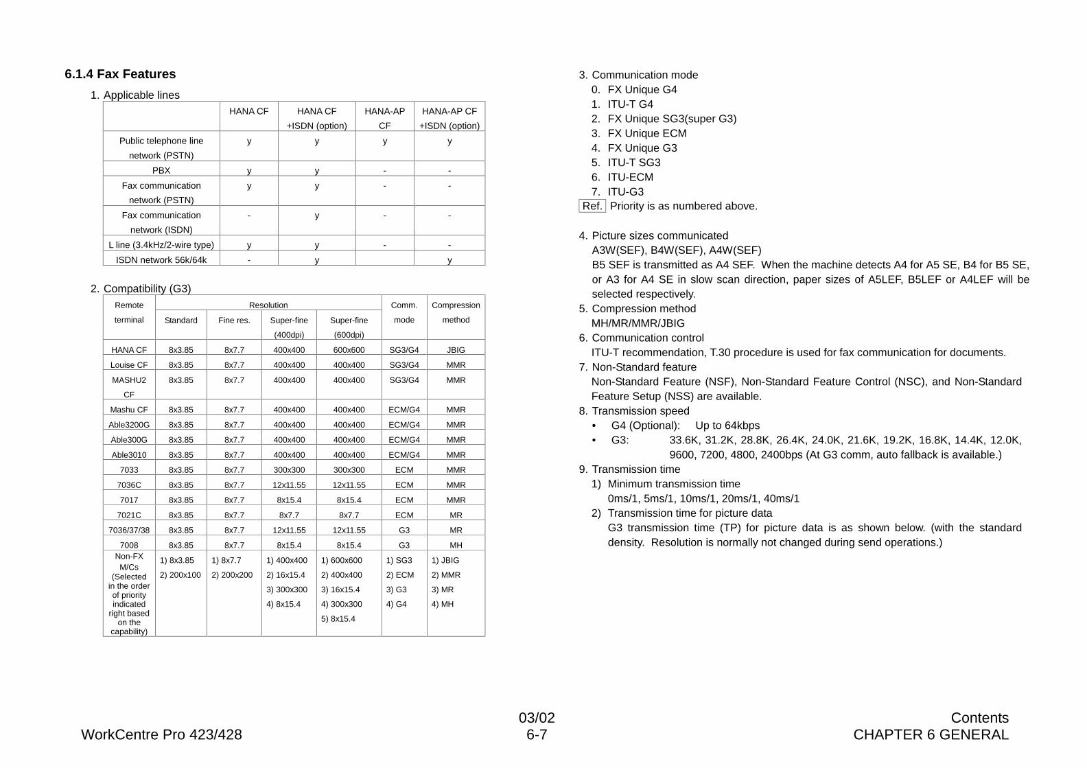
03/02 ContentsWorkCentre Pro 423/428 6-7 CHAPTER 6 GENERAL
6.1.4 Fax Features
1. Applicable linesHANA CF HANA CF
+ISDN (option)
HANA-AP
CF
HANA-AP CF
+ISDN (option)
Public telephone line
network (PSTN)
y y y y
PBX y y - -
Fax communication
network (PSTN)
y y - -
Fax communication
network (ISDN)
- y - -
L line (3.4kHz/2-wire type) y y - -
ISDN network 56k/64k - y y
2. Compatibility (G3)ResolutionRemote
terminal Standard Fine res. Super-fine
(400dpi)
Super-fine
(600dpi)
Comm.
mode
Compression
method
HANA CF 8x3.85 8x7.7 400x400 600x600 SG3/G4 JBIG
Louise CF 8x3.85 8x7.7 400x400 400x400 SG3/G4 MMR
MASHU2
CF
8x3.85 8x7.7 400x400 400x400 SG3/G4 MMR
Mashu CF 8x3.85 8x7.7 400x400 400x400 ECM/G4 MMR
Able3200G 8x3.85 8x7.7 400x400 400x400 ECM/G4 MMR
Able300G 8x3.85 8x7.7 400x400 400x400 ECM/G4 MMR
Able3010 8x3.85 8x7.7 400x400 400x400 ECM/G4 MMR
7033 8x3.85 8x7.7 300x300 300x300 ECM MMR
7036C 8x3.85 8x7.7 12x11.55 12x11.55 ECM MMR
7017 8x3.85 8x7.7 8x15.4 8x15.4 ECM MMR
7021C 8x3.85 8x7.7 8x7.7 8x7.7 ECM MR
7036/37/38 8x3.85 8x7.7 12x11.55 12x11.55 G3 MR
7008 8x3.85 8x7.7 8x15.4 8x15.4 G3 MHNon-FX
M/Cs(Selected
in the orderof priorityindicated
right basedon the
capability)
1) 8x3.85
2) 200x100
1) 8x7.7
2) 200x200
1) 400x400
2) 16x15.4
3) 300x300
4) 8x15.4
1) 600x600
2) 400x400
3) 16x15.4
4) 300x300
5) 8x15.4
1) SG3
2) ECM
3) G3
4) G4
1) JBIG
2) MMR
3) MR
4) MH
3. Communication mode0. FX Unique G41. ITU-T G42. FX Unique SG3(super G3)3. FX Unique ECM4. FX Unique G35. ITU-T SG36. ITU-ECM7. ITU-G3
Ref. Priority is as numbered above.
4. Picture sizes communicatedA3W(SEF), B4W(SEF), A4W(SEF)B5 SEF is transmitted as A4 SEF. When the machine detects A4 for A5 SE, B4 for B5 SE,or A3 for A4 SE in slow scan direction, paper sizes of A5LEF, B5LEF or A4LEF will beselected respectively.
5. Compression methodMH/MR/MMR/JBIG
6. Communication controlITU-T recommendation, T.30 procedure is used for fax communication for documents.
7. Non-Standard featureNon-Standard Feature (NSF), Non-Standard Feature Control (NSC), and Non-StandardFeature Setup (NSS) are available.
8. Transmission speed• G4 (Optional): Up to 64kbps• G3: 33.6K, 31.2K, 28.8K, 26.4K, 24.0K, 21.6K, 19.2K, 16.8K, 14.4K, 12.0K,
9600, 7200, 4800, 2400bps (At G3 comm, auto fallback is available.)9. Transmission time
1) Minimum transmission time0ms/1, 5ms/1, 10ms/1, 20ms/1, 40ms/1
2) Transmission time for picture dataG3 transmission time (TP) for picture data is as shown below. (with the standarddensity. Resolution is normally not changed during send operations.)
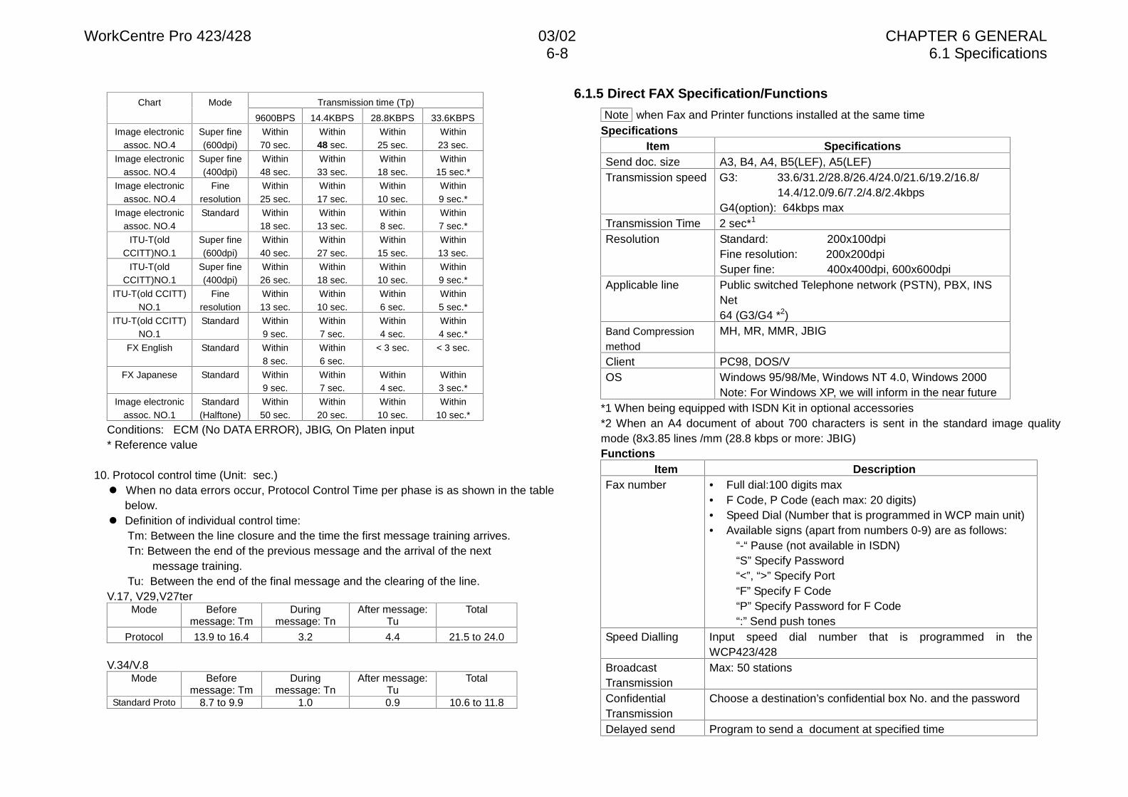
WorkCentre Pro 423/428 03/02 CHAPTER 6 GENERAL6-8 6.1 Specifications
Transmission time (Tp)Chart Mode
9600BPS 14.4KBPS 28.8KBPS 33.6KBPS
Image electronicassoc. NO.4
Super fine(600dpi)
Within70 sec.
Within48 sec.
Within25 sec.
Within23 sec.
Image electronicassoc. NO.4
Super fine(400dpi)
Within48 sec.
Within33 sec.
Within18 sec.
Within15 sec.*
Image electronicassoc. NO.4
Fineresolution
Within25 sec.
Within17 sec.
Within10 sec.
Within9 sec.*
Image electronicassoc. NO.4
Standard Within18 sec.
Within13 sec.
Within8 sec.
Within7 sec.*
ITU-T(oldCCITT)NO.1
Super fine(600dpi)
Within40 sec.
Within27 sec.
Within15 sec.
Within13 sec.
ITU-T(oldCCITT)NO.1
Super fine(400dpi)
Within26 sec.
Within18 sec.
Within10 sec.
Within9 sec.*
ITU-T(old CCITT)NO.1
Fineresolution
Within13 sec.
Within10 sec.
Within6 sec.
Within5 sec.*
ITU-T(old CCITT)NO.1
Standard Within9 sec.
Within7 sec.
Within4 sec.
Within4 sec.*
FX English Standard Within8 sec.
Within6 sec.
< 3 sec. < 3 sec.
FX Japanese Standard Within9 sec.
Within7 sec.
Within4 sec.
Within3 sec.*
Image electronicassoc. NO.1
Standard(Halftone)
Within50 sec.
Within20 sec.
Within10 sec.
Within10 sec.*
Conditions: ECM (No DATA ERROR), JBIG, On Platen input* Reference value
10. Protocol control time (Unit: sec.)l When no data errors occur, Protocol Control Time per phase is as shown in the table
below.l Definition of individual control time:
Tm: Between the line closure and the time the first message training arrives.Tn: Between the end of the previous message and the arrival of the next
message training.Tu: Between the end of the final message and the clearing of the line.
V.17, V29,V27terMode Before
message: TmDuring
message: TnAfter message:
TuTotal
Protocol 13.9 to 16.4 3.2 4.4 21.5 to 24.0
V.34/V.8Mode Before
message: TmDuring
message: TnAfter message:
TuTotal
Standard Proto 8.7 to 9.9 1.0 0.9 10.6 to 11.8
6.1.5 Direct FAX Specification/Functions
Note when Fax and Printer functions installed at the same timeSpecifications
Item SpecificationsSend doc. size A3, B4, A4, B5(LEF), A5(LEF)Transmission speed G3: 33.6/31.2/28.8/26.4/24.0/21.6/19.2/16.8/
14.4/12.0/9.6/7.2/4.8/2.4kbpsG4(option): 64kbps max
Transmission Time 2 sec*1
Resolution Standard: 200x100dpiFine resolution: 200x200dpiSuper fine: 400x400dpi, 600x600dpi
Applicable line Public switched Telephone network (PSTN), PBX, INSNet64 (G3/G4 *2)
Band Compression
method
MH, MR, MMR, JBIG
Client PC98, DOS/VOS Windows 95/98/Me, Windows NT 4.0, Windows 2000
Note: For Windows XP, we will inform in the near future*1 When being equipped with ISDN Kit in optional accessories*2 When an A4 document of about 700 characters is sent in the standard image qualitymode (8x3.85 lines /mm (28.8 kbps or more: JBIG)Functions
Item DescriptionFax number • Full dial:100 digits max
• F Code, P Code (each max: 20 digits)• Speed Dial (Number that is programmed in WCP main unit)• Available signs (apart from numbers 0-9) are as follows:
“-“ Pause (not available in ISDN)“S” Specify Password“<”, “>” Specify Port“F” Specify F Code“P” Specify Password for F Code“:” Send push tones
Speed Dialling Input speed dial number that is programmed in theWCP423/428
BroadcastTransmission
Max: 50 stations
ConfidentialTransmission
Choose a destination’s confidential box No. and the password
Delayed send Program to send a document at specified time
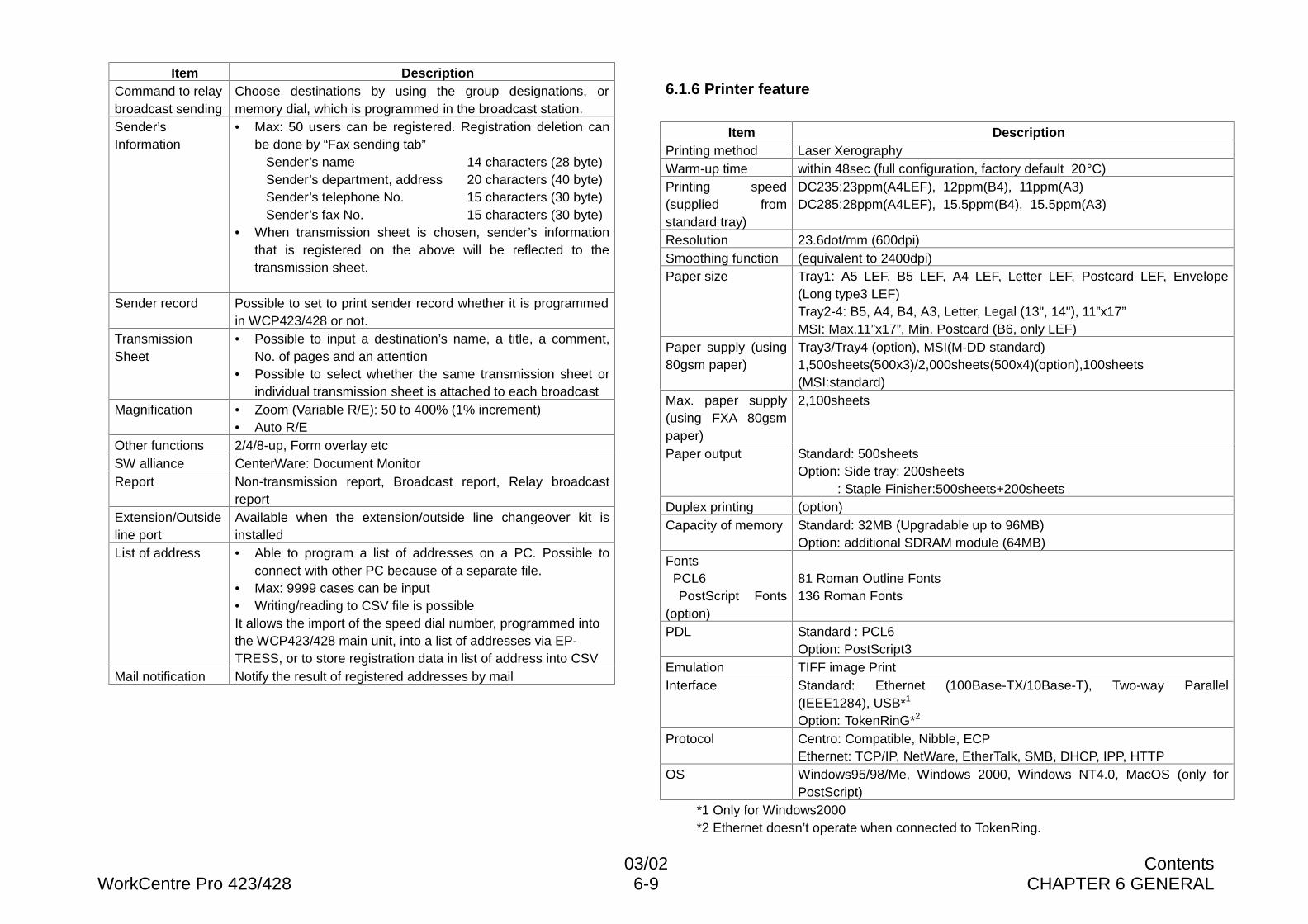
03/02 ContentsWorkCentre Pro 423/428 6-9 CHAPTER 6 GENERAL
Item DescriptionCommand to relaybroadcast sending
Choose destinations by using the group designations, ormemory dial, which is programmed in the broadcast station.
Sender’sInformation
• Max: 50 users can be registered. Registration deletion canbe done by “Fax sending tab”
Sender’s name 14 characters (28 byte)Sender’s department, address 20 characters (40 byte)Sender’s telephone No. 15 characters (30 byte)Sender’s fax No. 15 characters (30 byte)
• When transmission sheet is chosen, sender’s informationthat is registered on the above will be reflected to thetransmission sheet.
Sender record Possible to set to print sender record whether it is programmedin WCP423/428 or not.
TransmissionSheet
• Possible to input a destination’s name, a title, a comment,No. of pages and an attention
• Possible to select whether the same transmission sheet orindividual transmission sheet is attached to each broadcast
Magnification • Zoom (Variable R/E): 50 to 400% (1% increment)• Auto R/E
Other functions 2/4/8-up, Form overlay etcSW alliance CenterWare: Document MonitorReport Non-transmission report, Broadcast report, Relay broadcast
reportExtension/Outsideline port
Available when the extension/outside line changeover kit isinstalled
List of address • Able to program a list of addresses on a PC. Possible toconnect with other PC because of a separate file.
• Max: 9999 cases can be input• Writing/reading to CSV file is possibleIt allows the import of the speed dial number, programmed intothe WCP423/428 main unit, into a list of addresses via EP-TRESS, or to store registration data in list of address into CSV
Mail notification Notify the result of registered addresses by mail
6.1.6 Printer feature
Item DescriptionPrinting method Laser XerographyWarm-up time within 48sec (full configuration, factory default 20°C)Printing speed(supplied fromstandard tray)
DC235:23ppm(A4LEF), 12ppm(B4), 11ppm(A3)DC285:28ppm(A4LEF), 15.5ppm(B4), 15.5ppm(A3)
Resolution 23.6dot/mm (600dpi)Smoothing function (equivalent to 2400dpi)Paper size Tray1: A5 LEF, B5 LEF, A4 LEF, Letter LEF, Postcard LEF, Envelope
(Long type3 LEF)Tray2-4: B5, A4, B4, A3, Letter, Legal (13", 14"), 11”x17”MSI: Max.11”x17”, Min. Postcard (B6, only LEF)
Paper supply (using80gsm paper)
Tray3/Tray4 (option), MSI(M-DD standard)1,500sheets(500x3)/2,000sheets(500x4)(option),100sheets(MSI:standard)
Max. paper supply(using FXA 80gsmpaper)
2,100sheets
Paper output Standard: 500sheetsOption: Side tray: 200sheets
: Staple Finisher:500sheets+200sheetsDuplex printing (option)Capacity of memory Standard: 32MB (Upgradable up to 96MB)
Option: additional SDRAM module (64MB)Fonts PCL6
PostScript Fonts(option)
81 Roman Outline Fonts136 Roman Fonts
PDL Standard : PCL6Option: PostScript3
Emulation TIFF image PrintInterface Standard: Ethernet (100Base-TX/10Base-T), Two-way Parallel
(IEEE1284), USB*1
Option: TokenRinG*2
Protocol Centro: Compatible, Nibble, ECPEthernet: TCP/IP, NetWare, EtherTalk, SMB, DHCP, IPP, HTTP
OS Windows95/98/Me, Windows 2000, Windows NT4.0, MacOS (only forPostScript)
*1 Only for Windows2000*2 Ethernet doesn’t operate when connected to TokenRing.
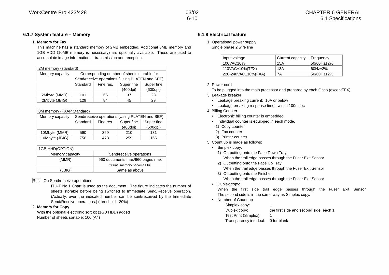
WorkCentre Pro 423/428 03/02 CHAPTER 6 GENERAL6-10 6.1 Specifications
6.1.7 System feature – Memory
1. Memory for FaxThis machine has a standard memory of 2MB embedded. Additional 8MB memory and1GB HDD (10MB memory is necessary) are optionally available. These are used toaccumulate image information at transmission and reception.
2M memory (standard)Corresponding number of sheets storable for
Send/receive operations (Using PLATEN and SEF)Memory capacity
Standard Fine res. Super fine(400dpi)
Super fine(600dpi)
2Mbyte (MMR) 101 66 37 232Mbyte (JBIG) 129 84 45 29
8M memory (FXAP Standard)Send/receive operations (Using PLATEN and SEF)Memory capacityStandard Fine res. Super fine
(400dpi)Super fine(600dpi)
10Mbyte (MMR) 590 369 210 13110Mbyte (JBIG) 756 473 259 165
1GB HHD(OPTION)Memory capacity Send/receive operations
(MMR) 960 documents max/960 pages maxOr until memory becomes full
(JBIG) Same as above
Ref. On Send/receive operationsITU-T No.1 Chart is used as the document. The figure indicates the number ofsheets storable before being switched to Immediate Send/Receive operation.(Actually, over the indicated number can be sent/received by the ImmediateSend/Receive operations.) (threshold: 20%)
2. Memory for CopyWith the optional electronic sort kit (1GB HDD) addedNumber of sheets sortable: 100 (A4)
6.1.8 Electrical feature
1. Operational power supplySingle phase 2 wire line
Input voltage Current capacity Frequency100VAC10% 15A 50/60Hz±2%110VAC±10%(TFX) 13A 60Hz±2%220-240VAC±10%(FXA) 7A 50/60Hz±2%
2. Power cordTo be plugged into the main processor and prepared by each Opco (exceptTFX).
3. Leakage breaker• Leakage breaking current: 10A or below• Leakage breaking response time: within 100msec
4. Billing Counter• Electronic billing counter is embedded.• Individual counter is equipped in each mode.
1) Copy counter2) Fax counter3) Printer counter
5. Count up is made as follows:• Simplex copy:
1) Outputting onto the Face Down TrayWhen the trail edge passes through the Fuser Exit Sensor
2) Outputting onto the Face Up TrayWhen the trail edge passes through the Fuser Exit Sensor
3) Outputting onto the FinisherWhen the trail edge passes through the Fuser Exit Sensor
• Duplex copy:When the first side trail edge passes through the Fuser Exit SensorThe second side is in the same way as Simplex copy.
• Number of Count upSimplex copy: 1Duplex copy: the first side and second side, each 1Test Print (Simplex): 1Transparency interleaf: 0 for blank
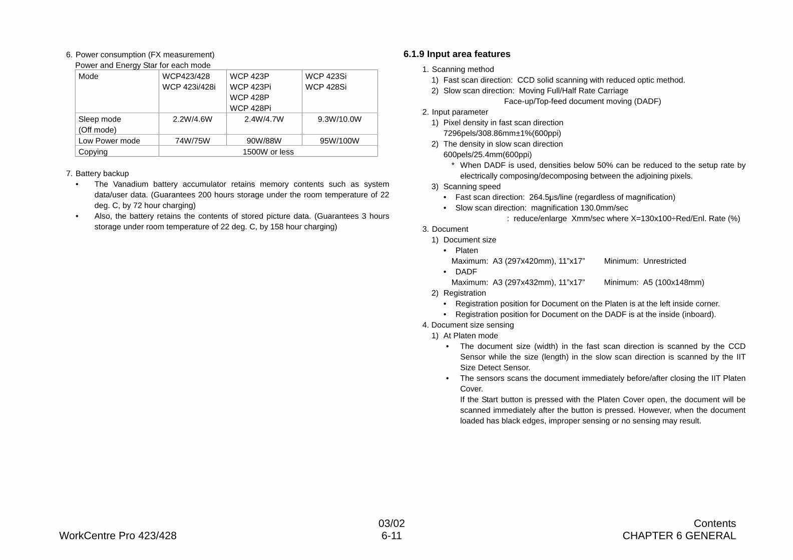
03/02 ContentsWorkCentre Pro 423/428 6-11 CHAPTER 6 GENERAL
6. Power consumption (FX measurement)Power and Energy Star for each modeMode WCP423/428
WCP 423i/428iWCP 423PWCP 423PiWCP 428PWCP 428Pi
WCP 423SiWCP 428Si
Sleep mode(Off mode)
2.2W/4.6W 2.4W/4.7W 9.3W/10.0W
Low Power mode 74W/75W 90W/88W 95W/100WCopying 1500W or less
7. Battery backup• The Vanadium battery accumulator retains memory contents such as system
data/user data. (Guarantees 200 hours storage under the room temperature of 22deg. C, by 72 hour charging)
• Also, the battery retains the contents of stored picture data. (Guarantees 3 hoursstorage under room temperature of 22 deg. C, by 158 hour charging)
6.1.9 Input area features
1. Scanning method1) Fast scan direction: CCD solid scanning with reduced optic method.2) Slow scan direction: Moving Full/Half Rate Carriage
Face-up/Top-feed document moving (DADF)2. Input parameter
1) Pixel density in fast scan direction7296pels/308.86mm±1%(600ppi)
2) The density in slow scan direction600pels/25.4mm(600ppi)
* When DADF is used, densities below 50% can be reduced to the setup rate byelectrically composing/decomposing between the adjoining pixels.
3) Scanning speed• Fast scan direction: 264.5 s/line (regardless of magnification)• Slow scan direction: magnification 130.0mm/sec
: reduce/enlarge Xmm/sec where X=130x100÷Red/Enl. Rate (%)3. Document
1) Document size• Platen
Maximum: A3 (297x420mm), 11”x17” Minimum: Unrestricted• DADF
Maximum: A3 (297x432mm), 11”x17” Minimum: A5 (100x148mm)2) Registration
• Registration position for Document on the Platen is at the left inside corner.• Registration position for Document on the DADF is at the inside (inboard).
4. Document size sensing1) At Platen mode
• The document size (width) in the fast scan direction is scanned by the CCDSensor while the size (length) in the slow scan direction is scanned by the IITSize Detect Sensor.
• The sensors scans the document immediately before/after closing the IIT PlatenCover.If the Start button is pressed with the Platen Cover open, the document will bescanned immediately after the button is pressed. However, when the documentloaded has black edges, improper sensing or no sensing may result.
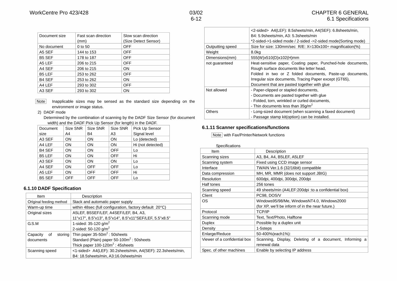
WorkCentre Pro 423/428 03/02 CHAPTER 6 GENERAL6-12 6.1 Specifications
Document size Fast scan direction(mm)
Slow scan direction(Size Detect Sensor)
No document 0 to 50 OFFA5 SEF 144 to 153 OFFB5 SEF 178 to 187 OFFA5 LEF 206 to 215 OFFA4 SEF 206 to 215 ONB5 LEF 253 to 262 OFFB4 SEF 253 to 262 ONA4 LEF 293 to 302 OFFA3 SEF 293 to 302 ON
Note Inapplicable sizes may be sensed as the standard size depending on theenvironment or image status.
2) DADF modeDetermined by the combination of scanning by the DADF Size Sensor (for document
width) and the DADF Pick Up Sensor (for length) in the DADF.Documentsize
Size SNRA4
Size SNRB4
Size SNRA3
Pick Up SensorSignal level
A3 SEF ON ON ON Lo (detected)A4 LEF ON ON ON Hi (not detected)B4 SEF ON ON OFF LoB5 LEF ON ON OFF HiA3 SEF ON ON ON LoA4 SEF ON OFF OFF LoA5 LEF ON OFF OFF HiB5 SEF OFF OFF OFF Lo
6.1.10 DADF Specification
Item DescriptionOriginal feeding method Stack and automatic paper supplyWarm-up time within 48sec (full configuration, factory default 20°C)Original sizes A5LEF, B5SEF/LEF, A4SEF/LEF, B4, A3,
11"x17”, 8.5”x13", 8.5”x14", 8.5"x11"SEF/LEF, 5.5”x8.5"G.S.M 1-sided: 35-120 g/m2
2-sided: 50-120 g/m2
Capacity of storingdocuments
Thin paper 35-50m2 : 50sheetsStandard (Plain) paper 50-100m2 : 50sheetsThick paper 100-120m2 : 45sheets
Scanning speed <1-sided> A4(LEF): 30.2sheets/min, A4(SEF): 22.3sheets/min,B4: 18.5sheets/min, A3:16.0sheets/min
<2-sided> A4(LEF): 8.5sheets/min, A4(SEF): 6.8sheets/min,B4: 5.9sheets/min, A3: 5.3sheets/min*2-sided->1-sided mode / 2-sided ->2-sided mode(Sorting mode)
Outputting speed Size for size: 130mm/sec R/E: X=130x100÷ magnification(%)Weight 8.0kgDimensions(mm) 555(W)x510(D)x102(H)mmnot guaranteed Heat-sensitive paper, Coating paper, Punched-hole documents,
Rough surface documents like letter head,Folded in two or Z folded documents, Paste-up documents,Irregular size documents, Tracing Paper except (GT65),Document that are pasted together with glue
Not allowed - Paper-clipped or stapled documents,- Documents are pasted together with glue- Folded, torn, wrinkled or curled documents,- Thin documents less than 35g/m2
Others - Long-sized document (when scanning a faxed document)- Passage stamp kit(option) can be installed.
6.1.11 Scanner specifications/functions
Note with Fax/Printer/Network functions
SpecificationsItem Description
Scanning sizes A3, B4, A4, B5LEF, A5LEFScanning system Fixed using CCD image sensorInterface TWAIN Ver.1.6 (32/16bit) compatibleData compression MH, MR, MMR (does not support JBIG)Resolution 600dpi, 400dpi, 300dpi, 200dpiHalf tones 256 tonesScanning speed 49 sheets/min (A4LEF:200dpi :to a confidential box)Client PC98, DOS/VOS Windows95/98/Me, WindowsNT4.0, Windows2000
(for XP, we’ll be inform of in the near future.)Protocol TCP/IPScanning mode Text, Text/Photo, HalftoneDuplex Possible by a duplex unitDensity 1-5stepsEnlarge/Reduce 50-400%(each1%):Viewer of a confidential box Scanning, Display, Deleting of a document, Informing a
renewal dataSpec. of other machines Enable by selecting IP address
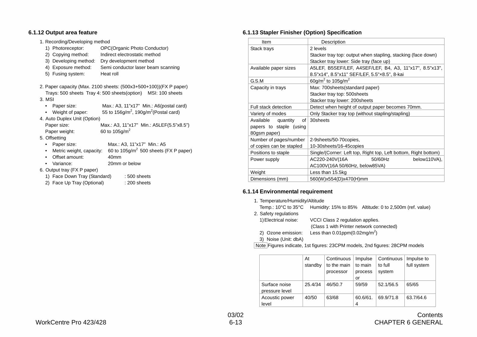
03/02 ContentsWorkCentre Pro 423/428 6-13 CHAPTER 6 GENERAL
6.1.12 Output area feature
1. Recording/Developing method1) Photoreceptor: OPC(Organic Photo Conductor)2) Copying method: Indirect electrostatic method3) Developing method: Dry development method4) Exposure method: Semi conductor laser beam scanning5) Fusing system: Heat roll
2. Paper capacity (Max. 2100 sheets: (500x3+500+100))(FX P paper)Trays: 500 sheets Tray 4: 500 sheets(option) MSI: 100 sheets
3. MSI• Paper size: Max.: A3, 11”x17” Min.: A6(postal card)• Weight of paper: 55 to 156g/m2, 190g/m2(Postal card)
4. Auto Duplex Unit (Option)Paper size: Max.: A3, 11”x17” Min.: A5LEF(5.5”x8.5”)Paper weight: 60 to 105g/m2
5. Offsetting• Paper size: Max.: A3, 11”x17” Min.: A5• Metric weight, capacity: 60 to 105g/m2 500 sheets (FX P paper)• Offset amount: 40mm• Variance: 20mm or below
6. Output tray (FX P paper)1) Face Down Tray (Standard) : 500 sheets2) Face Up Tray (Optional) : 200 sheets
6.1.13 Stapler Finisher (Option) Specification
Item DescriptionStack trays 2 levels
Stacker tray top: output when stapling, stacking (face down)Stacker tray lower: Side tray (face up)
Available paper sizes A5LEF, B5SEF/LEF, A4SEF/LEF, B4, A3, 11"x17", 8.5"x13",8.5"x14", 8.5"x11" SEF/LEF, 5.5"×8.5", 8-kai
G.S.M 60g/m2 to 105g/m2
Capacity in trays Max: 700sheets(standard paper)Stacker tray top: 500sheetsStacker tray lower: 200sheets
Full stack detection Detect when height of output paper becomes 70mm.Variety of modes Only Stacker tray top (without stapling/stapling)Available quantity ofpapers to staple (using80gsm paper)
30sheets
Number of pages/numberof copies can be stapled
2-9sheets/50-70copies,10-30sheets/16-45copies
Positions to staple Single/(Corner: Left top, Right top, Left bottom, Right bottom)Power supply AC220-240V(16A 50/60Hz below110VA),
AC100V(16A 50/60Hz, below85VA)Weight Less than 15.5kgDimensions (mm) 560(W)x554(D)x470(H)mm
6.1.14 Environmental requirement
1. Temperature/Humidity/AltitudeTemp.: 10°C to 35°C Humidity: 15% to 85% Altitude: 0 to 2,500m (ref. value)
2. Safety regulations1)Electrical noise: VCCI Class 2 regulation applies.
(Class 1 with Printer network connected)2) Ozone emission: Less than 0.01ppm(0.02mg/m2)3) Noise (Unit: dbA)
Note Figures indicate, 1st figures: 23CPM models, 2nd figures: 28CPM models
Atstandby
Continuousto the mainprocessor
Impulseto mainprocessor
Continuousto fullsystem
Impulse tofull system
Surface noisepressure level
25.4/34 46/50.7 59/59 52.1/56.5 65/65
Acoustic powerlevel
40/50 63/68 60.6/61.4
69.9/71.8 63.7/64.6
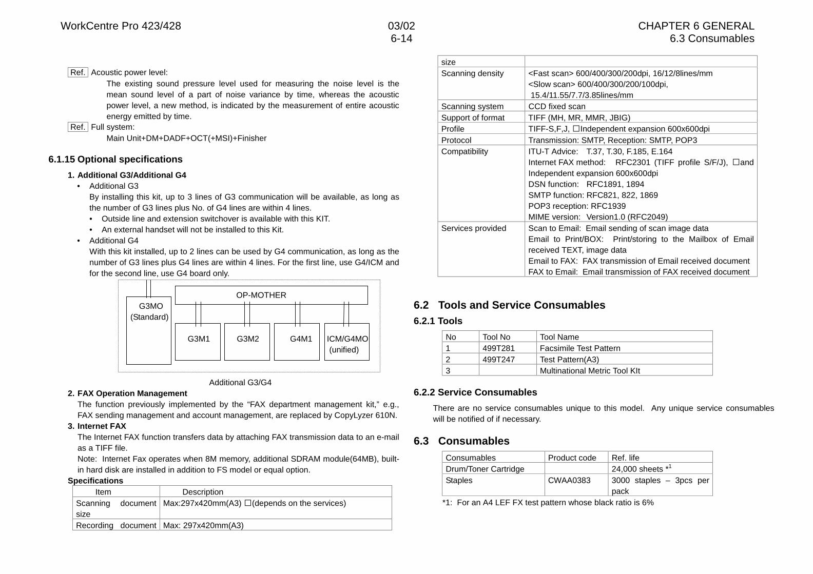
WorkCentre Pro 423/428 03/02 CHAPTER 6 GENERAL6-14 6.3 Consumables
Ref. Acoustic power level:The existing sound pressure level used for measuring the noise level is themean sound level of a part of noise variance by time, whereas the acousticpower level, a new method, is indicated by the measurement of entire acousticenergy emitted by time.
Ref. Full system:Main Unit+DM+DADF+OCT(+MSI)+Finisher
6.1.15 Optional specifications
1. Additional G3/Additional G4• Additional G3
By installing this kit, up to 3 lines of G3 communication will be available, as long asthe number of G3 lines plus No. of G4 lines are within 4 lines.• Outside line and extension switchover is available with this KIT.• An external handset will not be installed to this Kit.
• Additional G4With this kit installed, up to 2 lines can be used by G4 communication, as long as thenumber of G3 lines plus G4 lines are within 4 lines. For the first line, use G4/ICM andfor the second line, use G4 board only.
OP-MOTHER G3MO
(Standard)
G3M1 G3M2 G4M1 ICM/G4MO (unified)
Additional G3/G42. FAX Operation Management
The function previously implemented by the “FAX department management kit,” e.g.,FAX sending management and account management, are replaced by CopyLyzer 610N.
3. Internet FAXThe Internet FAX function transfers data by attaching FAX transmission data to an e-mailas a TIFF file.Note: Internet Fax operates when 8M memory, additional SDRAM module(64MB), built-in hard disk are installed in addition to FS model or equal option.
SpecificationsItem Description
Scanning documentsize
Max:297x420mm(A3) �(depends on the services)
Recording document Max: 297x420mm(A3)
sizeScanning density <Fast scan> 600/400/300/200dpi, 16/12/8lines/mm
<Slow scan> 600/400/300/200/100dpi, 15.4/11.55/7.7/3.85lines/mm
Scanning system CCD fixed scanSupport of format TIFF (MH, MR, MMR, JBIG)Profile TIFF-S,F,J, �Independent expansion 600x600dpiProtocol Transmission: SMTP, Reception: SMTP, POP3Compatibility ITU-T Advice: T.37, T.30, F.185, E.164
Internet FAX method: RFC2301 (TIFF profile S/F/J), �andIndependent expansion 600x600dpiDSN function: RFC1891, 1894SMTP function: RFC821, 822, 1869POP3 reception: RFC1939MIME version: Version1.0 (RFC2049)
Services provided Scan to Email: Email sending of scan image dataEmail to Print/BOX: Print/storing to the Mailbox of Emailreceived TEXT, image dataEmail to FAX: FAX transmission of Email received documentFAX to Email: Email transmission of FAX received document
6.2 Tools and Service Consumables6.2.1 Tools
No Tool No Tool Name1 499T281 Facsimile Test Pattern2 499T247 Test Pattern(A3)3 Multinational Metric Tool KIt
6.2.2 Service Consumables
There are no service consumables unique to this model. Any unique service consumableswill be notified of if necessary.
6.3 ConsumablesConsumables Product code Ref. lifeDrum/Toner Cartridge 24,000 sheets *1
Staples CWAA0383 3000 staples – 3pcs perpack
*1: For an A4 LEF FX test pattern whose black ratio is 6%
03/02 ContentsWorkCentre Pro 423/428 6-15 CHAPTER 6 GENERAL
6.4 Modification6.4.1 Symbology
When description contents vary by modification, the modification code is indicated usingthe following symbols:[Tag 1V]: Indicates that the description is applied to machines after Tag 1.[w/o Tag 1V]: Indicates that the description is applied to machines before Tag 1.
Symbol DescriptionIndicates a specific part which has been modified by thetag number within the circle.
Indicates that the specific part is illustrated as it appearsbefore it has been modified by the change identified bythe number within the circle.
6.4.2 Modification List
V code Title and description Product code Remarks123456789101112131415161718
V code Title and description Product code Remarks19202122232425262728293031323334353637383940414243444546474849505152535455
WorkCentre Pro 423/428 03/02 CHAPTER 6 GENERAL6-16 6.5 Installation
V code Title and description Product code Remarks56575859606162636465666768697071727374757678798081828384858687888990919293
V code Title and description Product code Remarks949596979899100
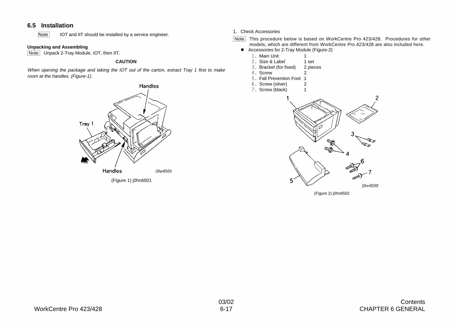
03/02 ContentsWorkCentre Pro 423/428 6-17 CHAPTER 6 GENERAL
6.5 InstallationNote IOT and IIT should be installed by a service engineer.
Unpacking and Assembling Note Unpack 2-Tray Module, IOT, then IIT.
CAUTION
When opening the package and taking the IOT out of the carton, extract Tray 1 first to makeroom at the handles. (Figure-1).
(Figure 1) j0hn6501
1. Check Accessories
Note This procedure below is based on WorkCentre Pro 423/428. Procedures for othermodels, which are different from WorkCentre Pro 423/428 are also included here.
l Accessories for 2-Tray Module (Figure-2)�� Main Unit 1�� Size & Label 1 set�� Bracket (for fixed) 2 pieces�� Screw 2�� Fall Prevention Foot 1�� Screw (silver) 2�� Screw (black) 1
(Figure 2) j0hn6502
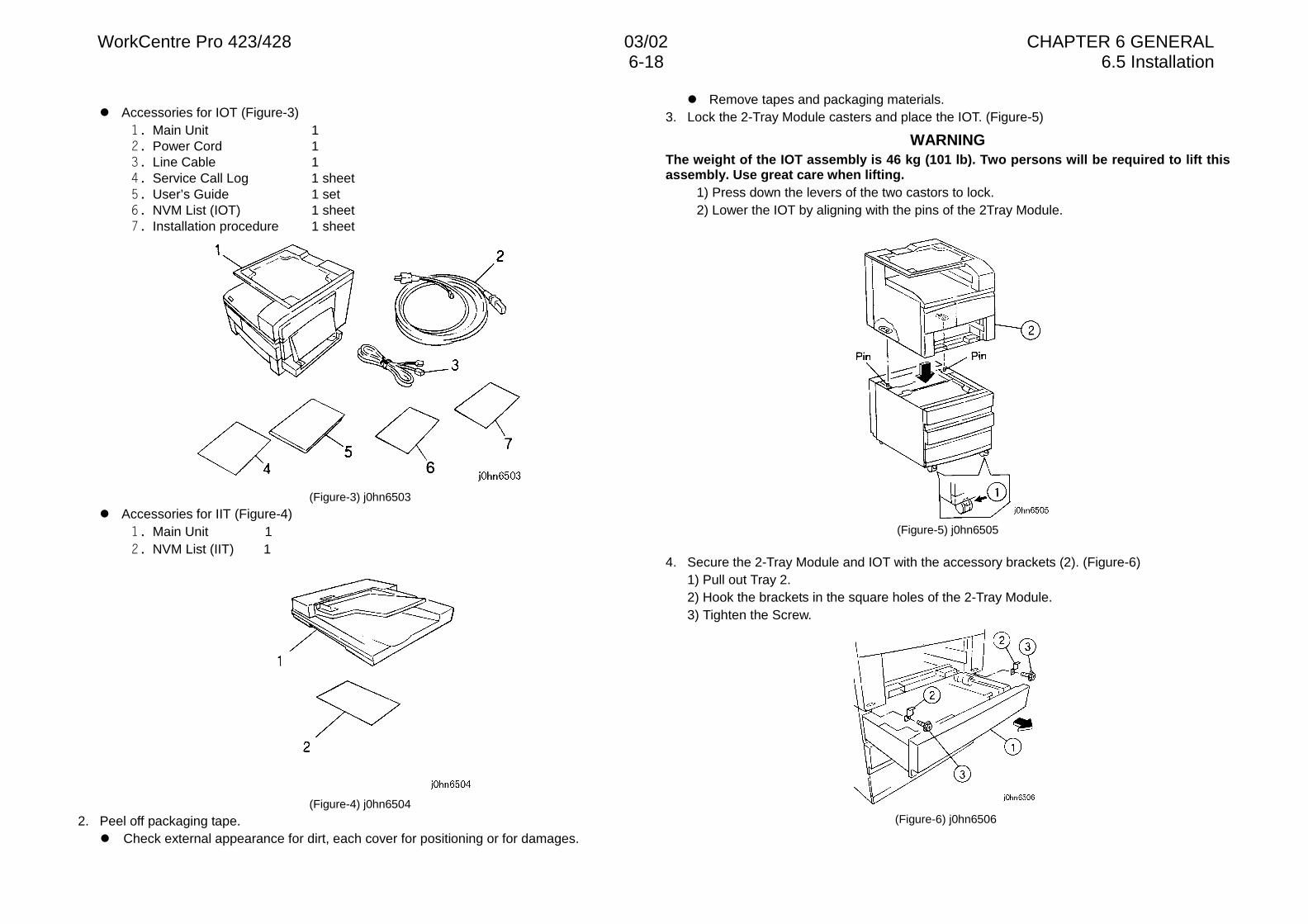
WorkCentre Pro 423/428 03/02 CHAPTER 6 GENERAL6-18 6.5 Installation
l Accessories for IOT (Figure-3)�� Main Unit 1�� Power Cord 1�� Line Cable 1�� Service Call Log 1 sheet�� User’s Guide 1 set�� NVM List (IOT) 1 sheet�� Installation procedure 1 sheet
(Figure-3) j0hn6503
l Accessories for IIT (Figure-4)�� Main Unit 1�� NVM List (IIT) 1
(Figure-4) j0hn6504
2. Peel off packaging tape.l Check external appearance for dirt, each cover for positioning or for damages.
l Remove tapes and packaging materials.3. Lock the 2-Tray Module casters and place the IOT. (Figure-5)
WARNINGThe weight of the IOT assembly is 46 kg (101 lb). Two persons will be required to lift thisassembly. Use great care when lifting.
1) Press down the levers of the two castors to lock.2) Lower the IOT by aligning with the pins of the 2Tray Module.
(Figure-5) j0hn6505
4. Secure the 2-Tray Module and IOT with the accessory brackets (2). (Figure-6)1) Pull out Tray 2.2) Hook the brackets in the square holes of the 2-Tray Module.3) Tighten the Screw.
(Figure-6) j0hn6506
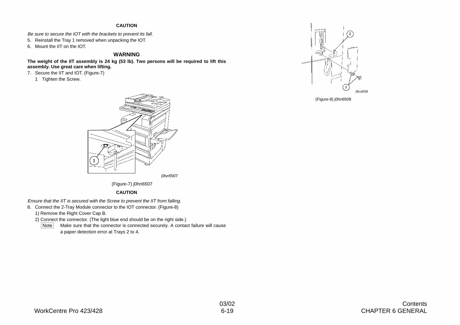
03/02 ContentsWorkCentre Pro 423/428 6-19 CHAPTER 6 GENERAL
CAUTION
Be sure to secure the IOT with the brackets to prevent its fall.5. Reinstall the Tray 1 removed when unpacking the IOT.6. Mount the IIT on the IOT.
WARNINGThe weight of the IIT assembly is 24 kg (53 lb). Two persons will be required to lift thisassembly. Use great care when lifting.7. Secure the IIT and IOT. (Figure-7)
1 Tighten the Screw.
(Figure-7) j0hn6507
CAUTION
Ensure that the IIT is secured with the Screw to prevent the IIT from falling.8. Connect the 2-Tray Module connector to the IOT connector. (Figure-8)
1) Remove the Right Cover Cap B.2) Connect the connector. (The light blue end should be on the right side.)
Note Make sure that the connector is connected securely. A contact failure will causea paper detection error at Trays 2 to 4.
(Figure-8) j0hn6508
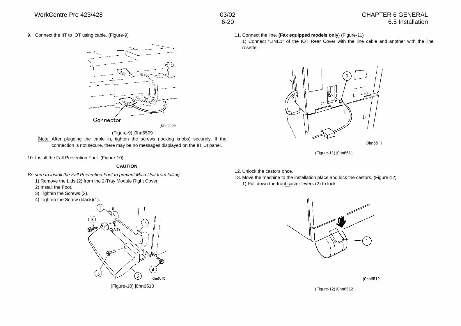
WorkCentre Pro 423/428 03/02 CHAPTER 6 GENERAL6-20 6.5 Installation
9. Connect the IIT to IOT using cable. (Figure-9)
(Figure-9) j0hn6509Note After plugging the cable in, tighten the screws (locking knobs) securely. If the
connection is not secure, there may be no messages displayed on the IIT UI panel.
10. Install the Fall Prevention Foot. (Figure-10).
CAUTION
Be sure to install the Fall Prevention Foot to prevent Main Unit from falling.1) Remove the Lids (2) from the 2-Tray Module Right Cover.2) Install the Foot.3) Tighten the Screws (2).4) Tighten the Screw (black)(1).
(Figure-10) j0hn6510
11. Connect the line. (Fax equipped models only) (Figure-11)1) Connect ”LINE1” of the IOT Rear Cover with the line cable and another with the linerosette.
(Figure-11) j0hn6511
12. Unlock the castors once.13. Move the machine to the installation place and lock the castors. (Figure-12)
1) Pull down the front caster levers (2) to lock.
(Figure-12) j0hn6512
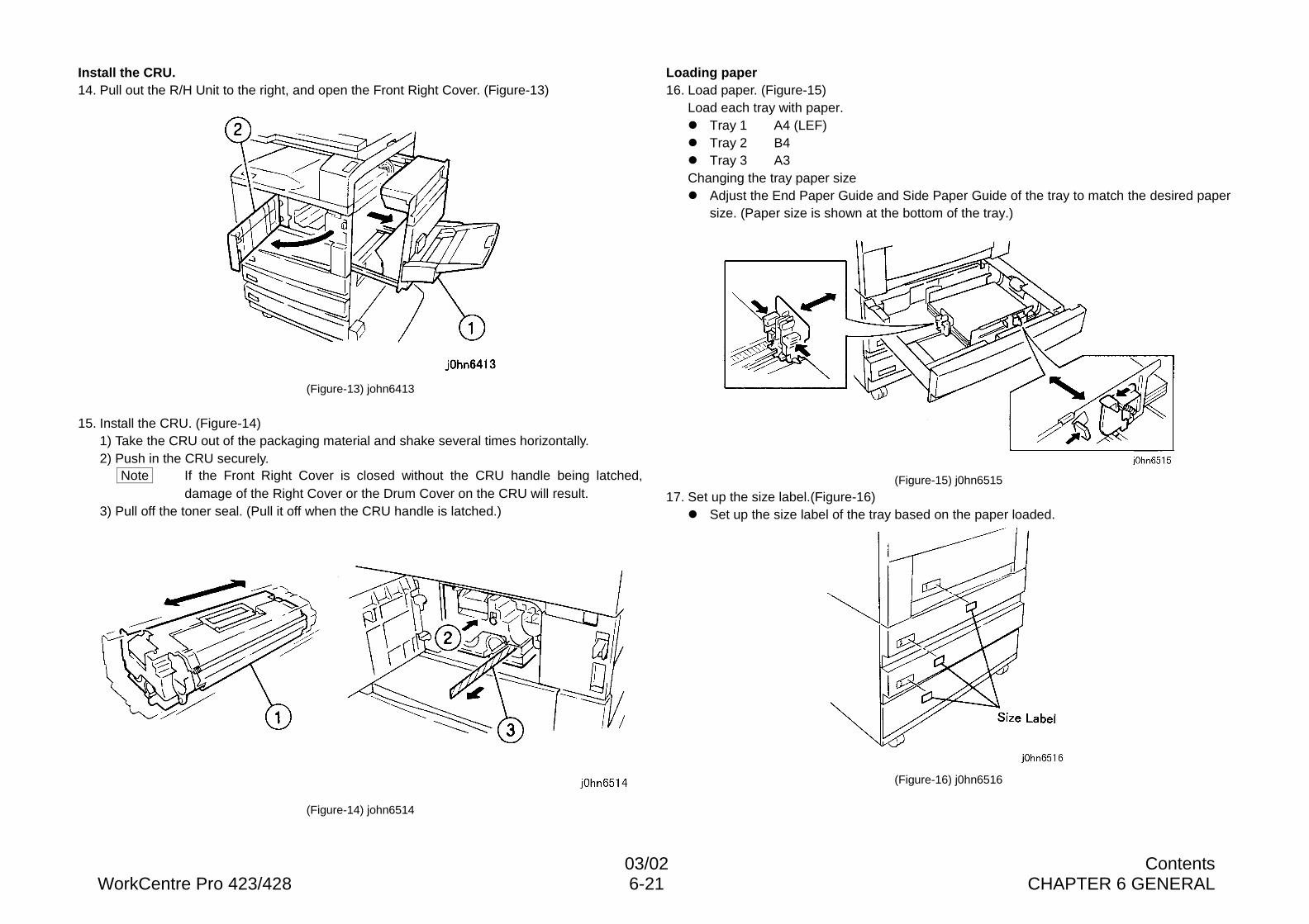
03/02 ContentsWorkCentre Pro 423/428 6-21 CHAPTER 6 GENERAL
Install the CRU.14. Pull out the R/H Unit to the right, and open the Front Right Cover. (Figure-13)
(Figure-13) john6413
15. Install the CRU. (Figure-14)1) Take the CRU out of the packaging material and shake several times horizontally.2) Push in the CRU securely.
Note If the Front Right Cover is closed without the CRU handle being latched,damage of the Right Cover or the Drum Cover on the CRU will result.
3) Pull off the toner seal. (Pull it off when the CRU handle is latched.)
(Figure-14) john6514
Loading paper16. Load paper. (Figure-15)
Load each tray with paper.l Tray 1 A4 (LEF)l Tray 2 B4l Tray 3 A3Changing the tray paper sizel Adjust the End Paper Guide and Side Paper Guide of the tray to match the desired paper
size. (Paper size is shown at the bottom of the tray.)
(Figure-15) j0hn6515
17. Set up the size label.(Figure-16)l Set up the size label of the tray based on the paper loaded.
(Figure-16) j0hn6516
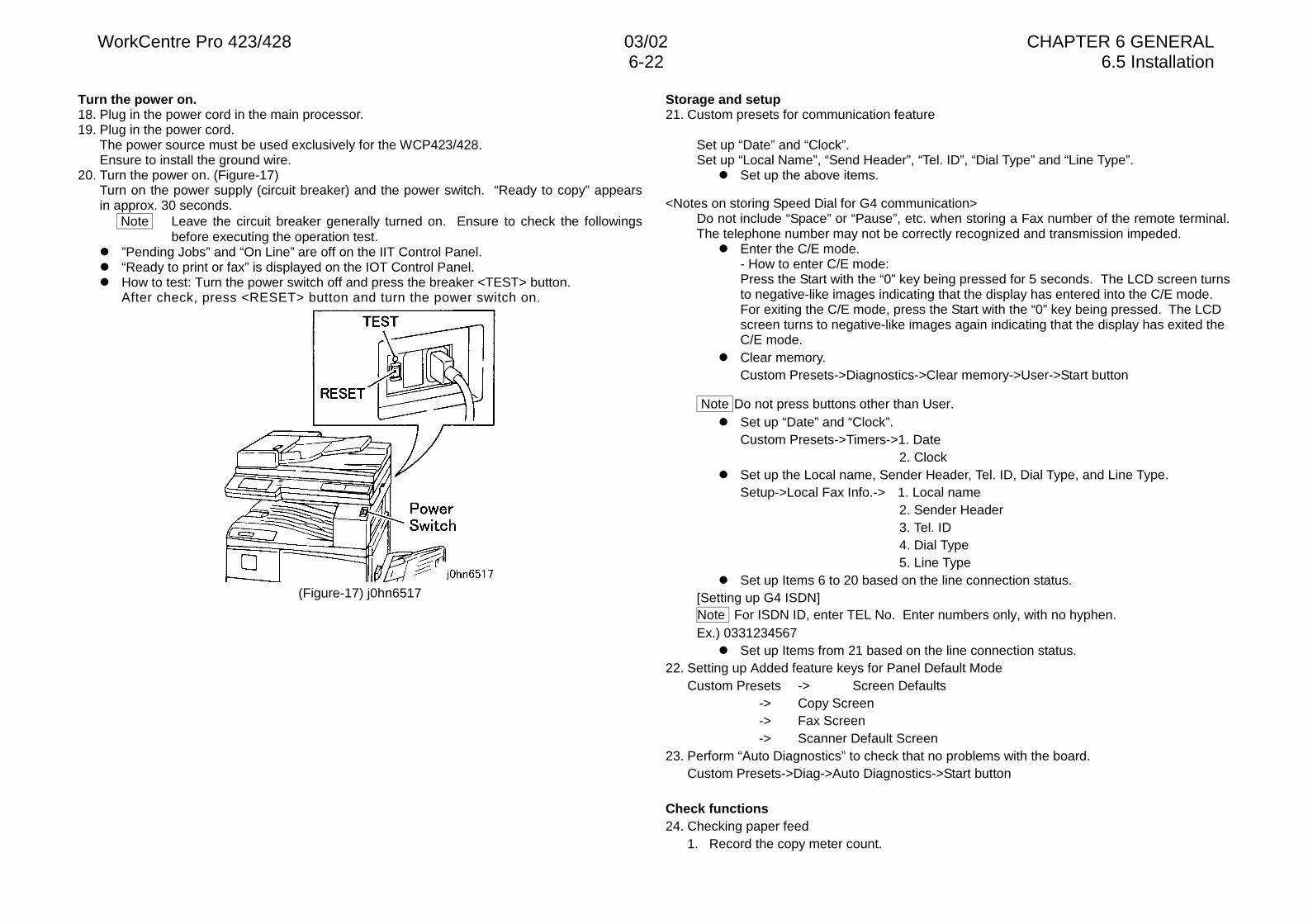
WorkCentre Pro 423/428 03/02 CHAPTER 6 GENERAL6-22 6.5 Installation
Turn the power on.18. Plug in the power cord in the main processor.19. Plug in the power cord.
The power source must be used exclusively for the WCP423/428.Ensure to install the ground wire.
20. Turn the power on. (Figure-17)Turn on the power supply (circuit breaker) and the power switch. “Ready to copy” appearsin approx. 30 seconds.
Note Leave the circuit breaker generally turned on. Ensure to check the followingsbefore executing the operation test.
l ”Pending Jobs” and “On Line” are off on the IIT Control Panel.l “Ready to print or fax” is displayed on the IOT Control Panel.l How to test: Turn the power switch off and press the breaker <TEST> button.
After check, press <RESET> button and turn the power switch on.
(Figure-17) j0hn6517
Storage and setup21. Custom presets for communication feature
Set up “Date” and “Clock”.Set up “Local Name”, “Send Header”, “Tel. ID”, “Dial Type” and “Line Type”.
l Set up the above items.
<Notes on storing Speed Dial for G4 communication>Do not include “Space” or “Pause”, etc. when storing a Fax number of the remote terminal.The telephone number may not be correctly recognized and transmission impeded.
l Enter the C/E mode.- How to enter C/E mode:Press the Start with the “0” key being pressed for 5 seconds. The LCD screen turnsto negative-like images indicating that the display has entered into the C/E mode.For exiting the C/E mode, press the Start with the “0” key being pressed. The LCDscreen turns to negative-like images again indicating that the display has exited theC/E mode.
l Clear memory.Custom Presets->Diagnostics->Clear memory->User->Start button
Note Do not press buttons other than User.l Set up “Date” and “Clock”.
Custom Presets->Timers->1. Date2. Clock
l Set up the Local name, Sender Header, Tel. ID, Dial Type, and Line Type.Setup->Local Fax Info.-> 1. Local name
2. Sender Header3. Tel. ID4. Dial Type5. Line Type
l Set up Items 6 to 20 based on the line connection status. [Setting up G4 ISDN]Note For ISDN ID, enter TEL No. Enter numbers only, with no hyphen.Ex.) 0331234567
l Set up Items from 21 based on the line connection status.22. Setting up Added feature keys for Panel Default Mode
Custom Presets -> Screen Defaults-> Copy Screen-> Fax Screen-> Scanner Default Screen
23. Perform “Auto Diagnostics” to check that no problems with the board.Custom Presets->Diag->Auto Diagnostics->Start button
Check functions24. Checking paper feed
1. Record the copy meter count.
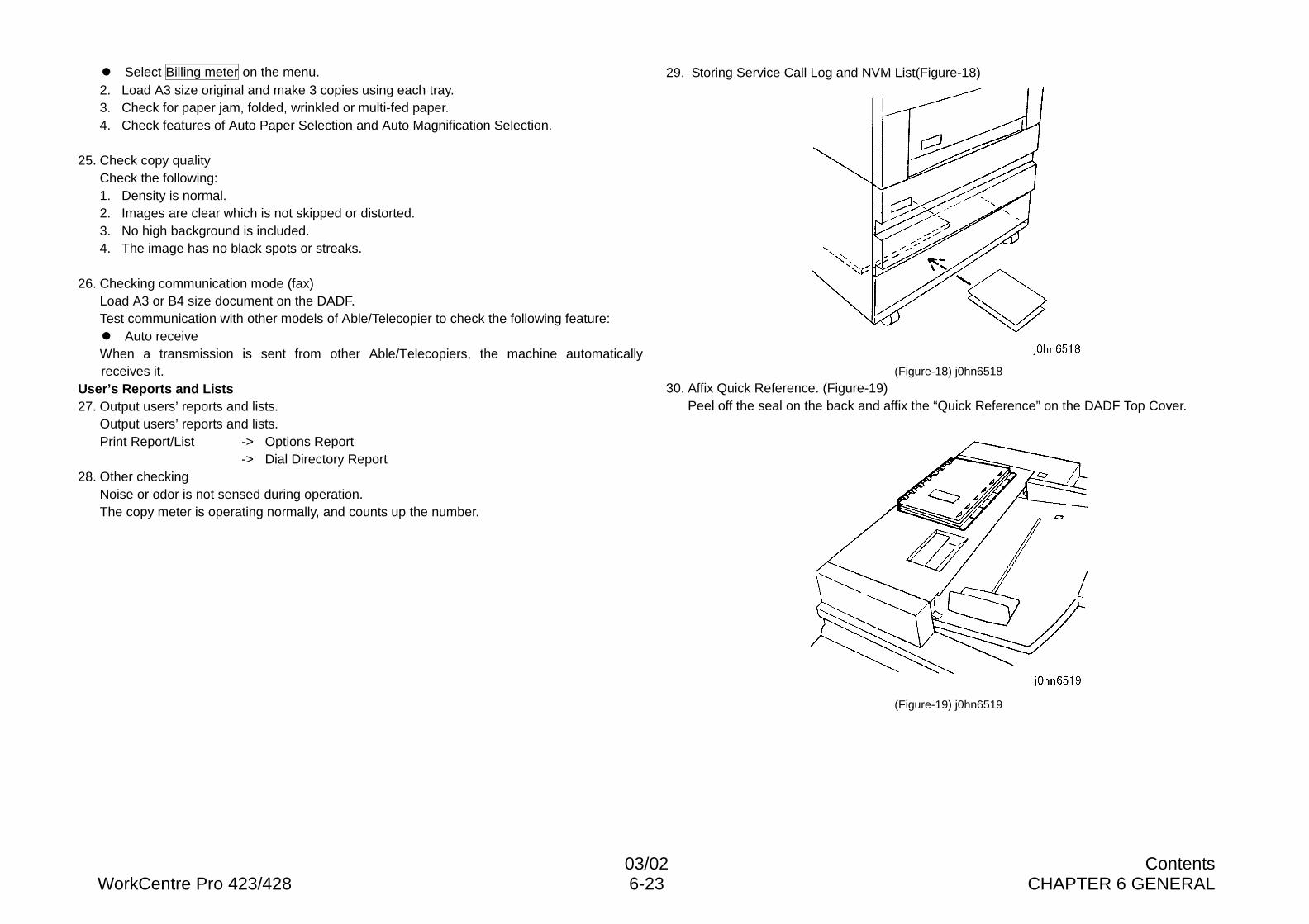
03/02 ContentsWorkCentre Pro 423/428 6-23 CHAPTER 6 GENERAL
l Select Billing meter on the menu.2. Load A3 size original and make 3 copies using each tray.3. Check for paper jam, folded, wrinkled or multi-fed paper.4. Check features of Auto Paper Selection and Auto Magnification Selection.
25. Check copy qualityCheck the following:1. Density is normal.2. Images are clear which is not skipped or distorted.3. No high background is included.4. The image has no black spots or streaks.
26. Checking communication mode (fax)Load A3 or B4 size document on the DADF.Test communication with other models of Able/Telecopier to check the following feature:l Auto receiveWhen a transmission is sent from other Able/Telecopiers, the machine automaticallyreceives it.
User’s Reports and Lists27. Output users’ reports and lists.
Output users’ reports and lists.Print Report/List -> Options Report
-> Dial Directory Report28. Other checking
Noise or odor is not sensed during operation.The copy meter is operating normally, and counts up the number.
29. Storing Service Call Log and NVM List(Figure-18)
(Figure-18) j0hn6518
30. Affix Quick Reference. (Figure-19)Peel off the seal on the back and affix the “Quick Reference” on the DADF Top Cover.
(Figure-19) j0hn6519
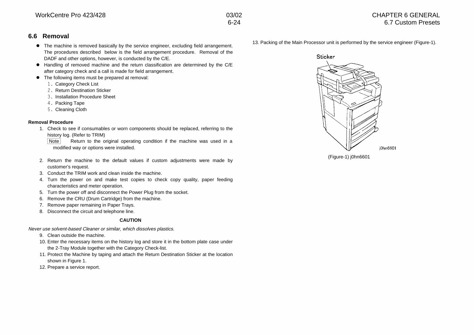
WorkCentre Pro 423/428 03/02 CHAPTER 6 GENERAL6-24 6.7 Custom Presets
6.6 Removall The machine is removed basically by the service engineer, excluding field arrangement.
The procedures described below is the field arrangement procedure. Removal of theDADF and other options, however, is conducted by the C/E.
l Handling of removed machine and the return classification are determined by the C/Eafter category check and a call is made for field arrangement.
l The following items must be prepared at removal:�� Category Check List�� Return Destination Sticker�� Installation Procedure Sheet�� Packing Tape�� Cleaning Cloth
Removal Procedure1. Check to see if consumables or worn components should be replaced, referring to the
history log. (Refer to TRIM) Note Return to the original operating condition if the machine was used in a
modified way or options were installed.
2. Return the machine to the default values if custom adjustments were made bycustomer’s request.
3. Conduct the TRIM work and clean inside the machine.4. Turn the power on and make test copies to check copy quality, paper feeding
characteristics and meter operation.5. Turn the power off and disconnect the Power Plug from the socket.6. Remove the CRU (Drum Cartridge) from the machine.7. Remove paper remaining in Paper Trays.8. Disconnect the circuit and telephone line.
CAUTION
Never use solvent-based Cleaner or similar, which dissolves plastics.9. Clean outside the machine.10. Enter the necessary items on the history log and store it in the bottom plate case under
the 2-Tray Module together with the Category Check-list.11. Protect the Machine by taping and attach the Return Destination Sticker at the location
shown in Figure 1.12. Prepare a service report.
13. Packing of the Main Processor unit is performed by the service engineer (Figure-1).
(Figure-1) j0hn6601
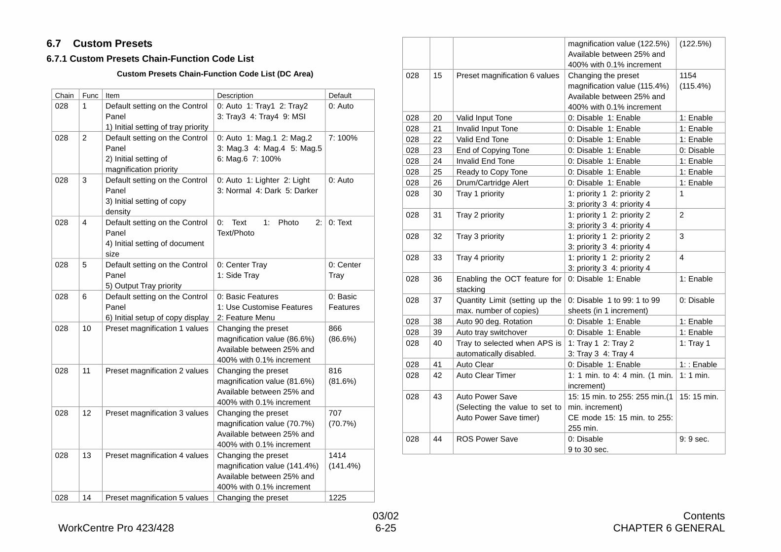
03/02 ContentsWorkCentre Pro 423/428 6-25 CHAPTER 6 GENERAL
6.7 Custom Presets6.7.1 Custom Presets Chain-Function Code List
Custom Presets Chain-Function Code List (DC Area)
Chain Func Item Description Default
028 1 Default setting on the ControlPanel1) Initial setting of tray priority
0: Auto 1: Tray1 2: Tray23: Tray3 4: Tray4 9: MSI
0: Auto
028 2 Default setting on the ControlPanel2) Initial setting ofmagnification priority
0: Auto 1: Mag.1 2: Mag.23: Mag.3 4: Mag.4 5: Mag.56: Mag.6 7: 100%
7: 100%
028 3 Default setting on the ControlPanel3) Initial setting of copydensity
0: Auto 1: Lighter 2: Light3: Normal 4: Dark 5: Darker
0: Auto
028 4 Default setting on the ControlPanel4) Initial setting of documentsize
0: Text 1: Photo 2:Text/Photo
0: Text
028 5 Default setting on the ControlPanel5) Output Tray priority
0: Center Tray1: Side Tray
0: CenterTray
028 6 Default setting on the ControlPanel6) Initial setup of copy display
0: Basic Features1: Use Customise Features2: Feature Menu
0: BasicFeatures
028 10 Preset magnification 1 values Changing the presetmagnification value (86.6%)Available between 25% and400% with 0.1% increment
866(86.6%)
028 11 Preset magnification 2 values Changing the presetmagnification value (81.6%)Available between 25% and400% with 0.1% increment
816(81.6%)
028 12 Preset magnification 3 values Changing the presetmagnification value (70.7%)Available between 25% and400% with 0.1% increment
707(70.7%)
028 13 Preset magnification 4 values Changing the presetmagnification value (141.4%)Available between 25% and400% with 0.1% increment
1414(141.4%)
028 14 Preset magnification 5 values Changing the preset 1225
magnification value (122.5%)Available between 25% and400% with 0.1% increment
(122.5%)
028 15 Preset magnification 6 values Changing the presetmagnification value (115.4%)Available between 25% and400% with 0.1% increment
1154(115.4%)
028 20 Valid Input Tone 0: Disable 1: Enable 1: Enable028 21 Invalid Input Tone 0: Disable 1: Enable 1: Enable028 22 Valid End Tone 0: Disable 1: Enable 1: Enable028 23 End of Copying Tone 0: Disable 1: Enable 0: Disable028 24 Invalid End Tone 0: Disable 1: Enable 1: Enable028 25 Ready to Copy Tone 0: Disable 1: Enable 1: Enable028 26 Drum/Cartridge Alert 0: Disable 1: Enable 1: Enable028 30 Tray 1 priority 1: priority 1 2: priority 2
3: priority 3 4: priority 41
028 31 Tray 2 priority 1: priority 1 2: priority 23: priority 3 4: priority 4
2
028 32 Tray 3 priority 1: priority 1 2: priority 23: priority 3 4: priority 4
3
028 33 Tray 4 priority 1: priority 1 2: priority 23: priority 3 4: priority 4
4
028 36 Enabling the OCT feature forstacking
0: Disable 1: Enable 1: Enable
028 37 Quantity Limit (setting up themax. number of copies)
0: Disable 1 to 99: 1 to 99sheets (in 1 increment)
0: Disable
028 38 Auto 90 deg. Rotation 0: Disable 1: Enable 1: Enable028 39 Auto tray switchover 0: Disable 1: Enable 1: Enable028 40 Tray to selected when APS is
automatically disabled.1: Tray 1 2: Tray 23: Tray 3 4: Tray 4
1: Tray 1
028 41 Auto Clear 0: Disable 1: Enable 1: : Enable028 42 Auto Clear Timer 1: 1 min. to 4: 4 min. (1 min.
increment)1: 1 min.
028 43 Auto Power Save(Selecting the value to set toAuto Power Save timer)
15: 15 min. to 255: 255 min.(1min. increment)CE mode 15: 15 min. to 255:255 min.
15: 15 min.
028 44 ROS Power Save 0: Disable9 to 30 sec.
9: 9 sec.
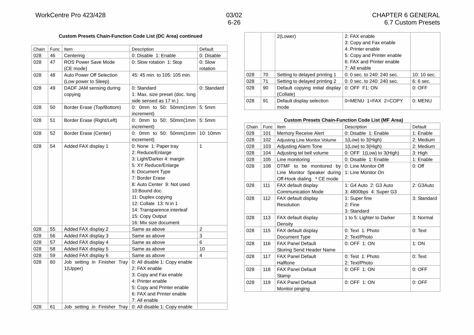
WorkCentre Pro 423/428 03/02 CHAPTER 6 GENERAL6-26 6.7 Custom Presets
Custom Presets Chain-Function Code List (DC Area) continued
Chain Func Item Description Default
028 46 Centering 0: Disable 1: Enable 0: Disable028 47 ROS Power Save Mode
(CE mode)0: Slow rotation 1: Stop 0: Slow
rotation028 48 Auto Power Off Selection
(Low power to Sleep)45: 45 min. to 105: 105 min.
028 49 DADF JAM sensing duringcopying
0: Standard1: Max. size preset (doc. longside sensed as 17 in.)
0: Standard
028 50 Border Erase (Top/Bottom) 0: 0mm to 50: 50mm(1mmincrement)
5: 5mm
028 51 Border Erase (Right/Left) 0: 0mm to 50: 50mm(1mmincrement)
5: 5mm
028 52 Border Erase (Center) 0: 0mm to 50: 50mm(1mmincrement)
10: 10mm
028 54 Added FAX display 1 0: None 1: Paper tray2: Reduce/Enlarge3: Light/Darker 4: margin5: XY Reduce/Enlarge6: Document Type7: Border Erase8: Auto Center 9: Not used10:Bound doc.11: Duplex copying12: Collate 13: N in 114: Transparence interleaf15: Copy Output16: Mix size document
1
028 55 Added FAX display 2 Same as above 2028 56 Added FAX display 3 Same as above 3028 57 Added FAX display 4 Same as above 6028 58 Added FAX display 5 Same as above 10028 59 Added FAX display 6 Same as above 4028 60 Job setting in Finisher Tray
1(Upper)0: All disable 1: Copy enable2: FAX enable3: Copy and Fax enable4: Printer enable5: Copy and Printer enable6: FAX and Printer enable7: All enable
028 61 Job setting in Finisher Tray 0: All disable 1: Copy enable
2(Lower) 2: FAX enable3: Copy and Fax enable4: Printer enable5: Copy and Printer enable6: FAX and Printer enable7: All enable
028 70 Setting to delayed printing 1 0: 0 sec. to 240: 240 sec. 10: 10 sec.028 71 Setting to delayed printing 2 0: 0 sec. to 240: 240 sec. 6: 6 sec.028 90 Default copying initial display
(Collate)0: OFF F1: ON 0: OFF
028 91 Default display selectionmode
0=MENU 1=FAX 2=COPY 0: MENU
Custom Presets Chain-Function Code List (MF Area)Chain Func Item Description Default
028 101 Memory Receive Alert 0: Disable 1: Enable 1: Enable028 102 Adjusting Line Monitor Volume 1(Low) to 3(High) 2: Medium028 103 Adjusting Alarm Tone 1(Low) to 3(High) 2: Medium028 104 Adjusting tel bell volume 0: OFF 1(Low) to 3(High) 3: High028 105 Line monitoring 0: Disable 1: Enable 1: Enable028 108 DTMF to be monitored by
Line Monitor Speaker duringOff-Hook dialing. * CE mode
0: Line Monitor Off1: Line Monitor On
0: Off
028 111 FAX default displayCommunication Mode
1: G4 Auto 2: G3 Auto3: 4800bps 4: Super G3
2: G3Auto
028 112 FAX default displayResolution
1: Super fine2: Fine3: Standard
3: Standard
028 113 FAX default displayDensity
1 to 5: Lighter to Darker 3: Normal
028 115 FAX default displayDocument Type
0: Text 1: Photo2: Text/Photo
0: Text
028 116 FAX Panel DefaultStoring Send Header Name
0: OFF 1: ON 1: ON
028 117 FAX Panel DefaultHalftone
0: Test 1: Photo2: Text/Photo
0: Text
028 118 FAX Panel DefaultStamp
0: OFF 1: ON 0: OFF
028 119 FAX Panel DefaultMonitor pinging
0: OFF 1: ON 0: OFF
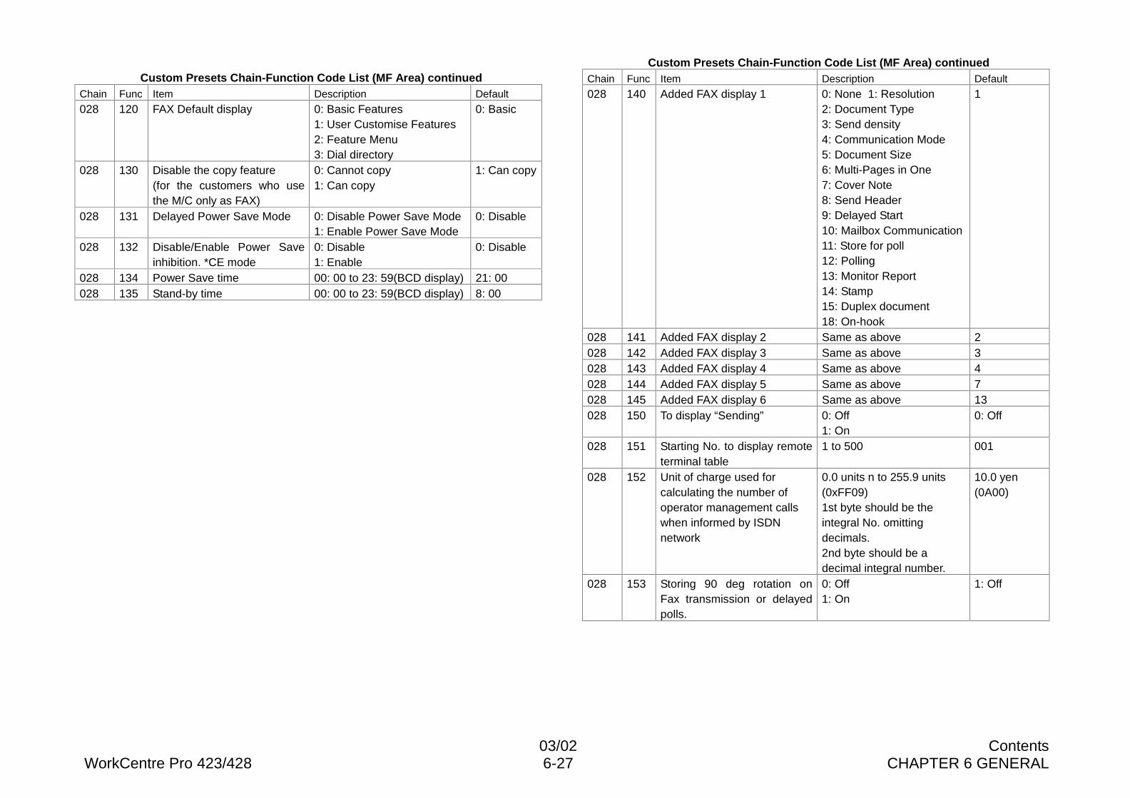
03/02 ContentsWorkCentre Pro 423/428 6-27 CHAPTER 6 GENERAL
Custom Presets Chain-Function Code List (MF Area) continuedChain Func Item Description Default
028 120 FAX Default display 0: Basic Features1: User Customise Features2: Feature Menu3: Dial directory
0: Basic
028 130 Disable the copy feature(for the customers who usethe M/C only as FAX)
0: Cannot copy1: Can copy
1: Can copy
028 131 Delayed Power Save Mode 0: Disable Power Save Mode1: Enable Power Save Mode
0: Disable
028 132 Disable/Enable Power Saveinhibition. *CE mode
0: Disable1: Enable
0: Disable
028 134 Power Save time 00: 00 to 23: 59(BCD display) 21: 00028 135 Stand-by time 00: 00 to 23: 59(BCD display) 8: 00
Custom Presets Chain-Function Code List (MF Area) continuedChain Func Item Description Default
028 140 Added FAX display 1 0: None 1: Resolution2: Document Type3: Send density4: Communication Mode5: Document Size6: Multi-Pages in One7: Cover Note8: Send Header9: Delayed Start10: Mailbox Communication11: Store for poll12: Polling13: Monitor Report14: Stamp15: Duplex document18: On-hook
1
028 141 Added FAX display 2 Same as above 2028 142 Added FAX display 3 Same as above 3028 143 Added FAX display 4 Same as above 4028 144 Added FAX display 5 Same as above 7028 145 Added FAX display 6 Same as above 13028 150 To display “Sending” 0: Off
1: On0: Off
028 151 Starting No. to display remoteterminal table
1 to 500 001
028 152 Unit of charge used forcalculating the number ofoperator management callswhen informed by ISDNnetwork
0.0 units n to 255.9 units(0xFF09)1st byte should be theintegral No. omittingdecimals.2nd byte should be adecimal integral number.
10.0 yen(0A00)
028 153 Storing 90 deg rotation onFax transmission or delayedpolls.
0: Off1: On
1: Off
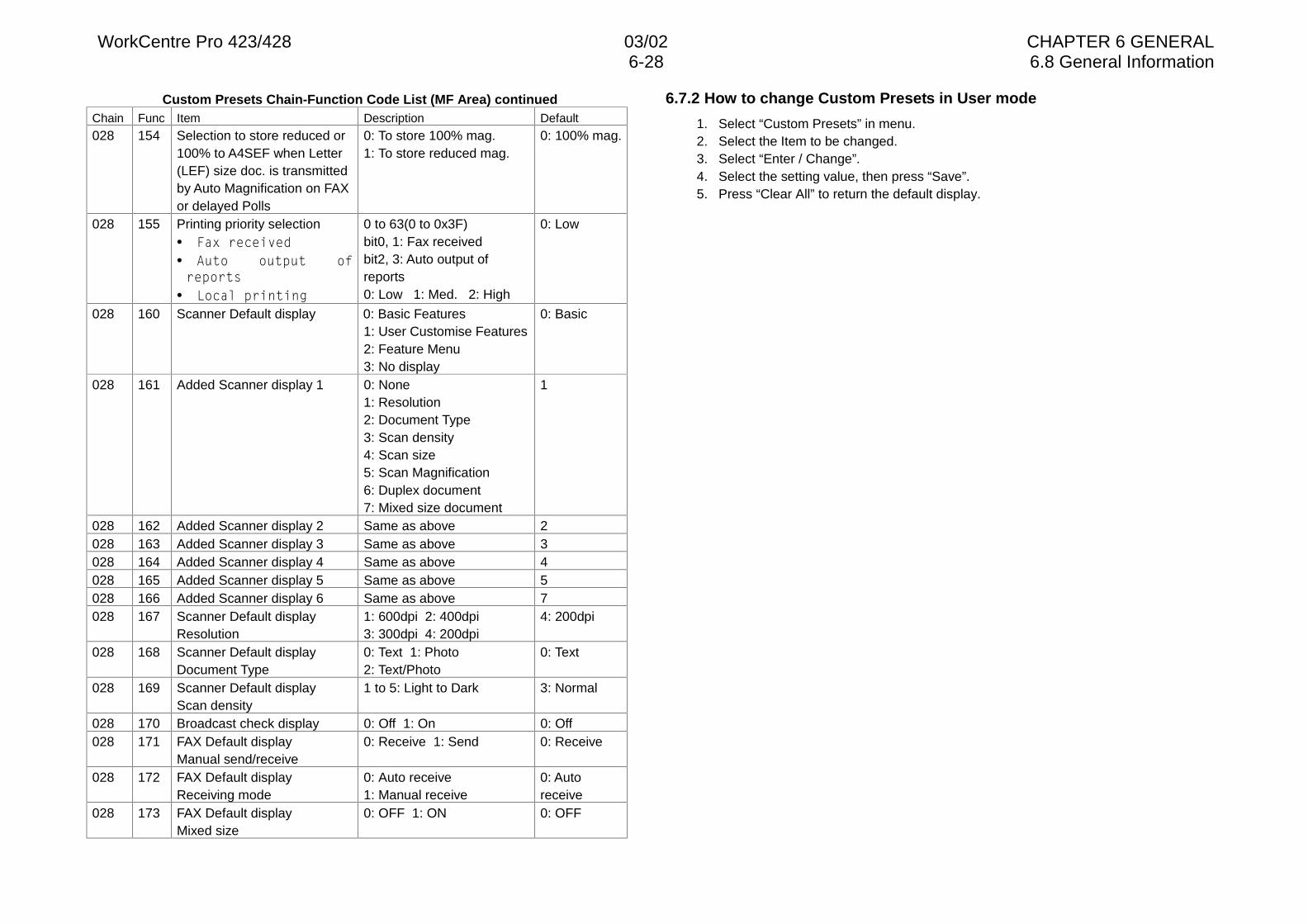
WorkCentre Pro 423/428 03/02 CHAPTER 6 GENERAL6-28 6.8 General Information
Custom Presets Chain-Function Code List (MF Area) continuedChain Func Item Description Default
028 154 Selection to store reduced or100% to A4SEF when Letter(LEF) size doc. is transmittedby Auto Magnification on FAXor delayed Polls
0: To store 100% mag.1: To store reduced mag.
0: 100% mag.
028 155 Printing priority selection• )D[�UHFHLYHG• $XWR� RXWSXW� RIUHSRUWV
• /RFDO�SULQWLQJ
0 to 63(0 to 0x3F)bit0, 1: Fax receivedbit2, 3: Auto output ofreports0: Low 1: Med. 2: High
0: Low
028 160 Scanner Default display 0: Basic Features1: User Customise Features2: Feature Menu3: No display
0: Basic
028 161 Added Scanner display 1 0: None1: Resolution2: Document Type3: Scan density4: Scan size5: Scan Magnification6: Duplex document7: Mixed size document
1
028 162 Added Scanner display 2 Same as above 2028 163 Added Scanner display 3 Same as above 3028 164 Added Scanner display 4 Same as above 4028 165 Added Scanner display 5 Same as above 5028 166 Added Scanner display 6 Same as above 7028 167 Scanner Default display
Resolution1: 600dpi 2: 400dpi3: 300dpi 4: 200dpi
4: 200dpi
028 168 Scanner Default displayDocument Type
0: Text 1: Photo2: Text/Photo
0: Text
028 169 Scanner Default displayScan density
1 to 5: Light to Dark 3: Normal
028 170 Broadcast check display 0: Off 1: On 0: Off028 171 FAX Default display
Manual send/receive0: Receive 1: Send 0: Receive
028 172 FAX Default displayReceiving mode
0: Auto receive1: Manual receive
0: Autoreceive
028 173 FAX Default displayMixed size
0: OFF 1: ON 0: OFF
6.7.2 How to change Custom Presets in User mode
1. Select “Custom Presets” in menu.2. Select the Item to be changed.3. Select “Enter / Change”.4. Select the setting value, then press “Save”.5. Press “Clear All” to return the default display.

03/02 ContentsWorkCentre Pro 423/428 6-29 CHAPTER 6 GENERAL
6.8 General Information6.8.1 Forced polling of documents stored in memory
When documents stored for the memory send or reserved for delayed send remain withoutbeing printed, they can be picked up from a remote terminal using the polling option.
1. Summary of the forced polling featureAll of documents reserved for delayed send and pending jobs can be picked up usingthe polling option by changing system data.Requirements for forced polling:1) The terminal must be capable of being set to the diagnostic (C/E) mode.
The operation is activated in the Diagnostic (C/E) mode because the system dataneed to be changed. When the Control Panel is locked or any other status disablingthe machine to enter the diagnostic (C/E) mode, you cannot activate forced polling.
2) The documents stored in memory for a delayed send or pending jobs are applicableto this feature. Any other irretrievable documents, such as task file, or those whosedata were destroyed, will be automatically deleted.
3) G3 polling realizes batch polling. G4 polling requires the polling operation to berepeated the number of documents.
2. Operation procedure1) Disconnect all lines. *1*1: To disable all incoming calls during operation.2) Enter CE MODE. *2*2: “0” + “Start” (5 sec.)3) Chain=058 and Func=590 to “1”. *3*3: Select Menu->Custom Presets->Diagnostics-> Chain Func->058/590->Start-
>Enter->1->Restart, then back to the Menu screen.4) Connect the line. *4*4: Connect only the line necessary for polling.5) Active polling and pick up documents. *5 (should be in CE MODE)*5: When polling is complete, documents stored in memory are deleted.
After polling is complete, return system data Chain=058, Function=590 tothe original “0” to exit the CE MODE.Connect the lines, if any.
3. Notes on Forced Polling1) Ensure you have the customer’s approval. (Ask the customer to attend theoperation if possible.)2) Percentage of recovery is not necessarily 100%. Explain to the customer that there
are documents that cannot be deleted by forced polling because of the conditions inwhich they have been stored.
3) After documents are output by polling, the terminal automatically deletes thedocuments one by one. In case any problem or accident occurs at the remoteterminal during this operation, documents may be deleted before being output. Be
sure to activate the operation carefully.4) Polling from the local station to the local station is prohibited on a machine having
additional G3M and additional G4M and containing several lines. This loopbackpolling will erase all files.
6.8.2 How to By-pass the IOT Password Protection
1) In “Ready to Print” mode, hold down the arrow-up button for at least 3 sec.2) Release the button, then press it three times at short intervals.After this, you should be able to access the menu without needing a password.
6.8.3 Location of Serial Number Plate
To access the machine serial number plate, pull out the right-hand cover. The plate islocated on the machine frame, just below the fuser.
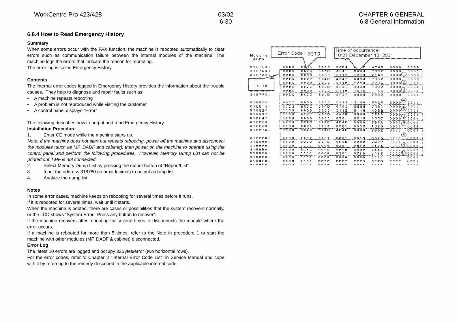
WorkCentre Pro 423/428 03/02 CHAPTER 6 GENERAL6-30 6.8 General Information
6.8.4 How to Read Emergency History
SummaryWhen some errors occur with the FAX function, the machine is rebooted automatically to clearerrors such as communication failure between the internal modules of the machine. Themachine logs the errors that indicate the reason for rebooting.The error log is called Emergency History.
ContentsThe internal error codes logged in Emergency History provides the information about the troublecauses. They help to diagnose and repair faults such as:• A machine repeats rebooting• A problem is not reproduced while visiting the customer• A control panel displays “Error”
The following describes how to output and read Emergency History.Installation Procedure1. Enter CE mode while the machine starts up.Note: If the machine does not start but repeats rebooting, power off the machine and disconnectthe modules (such as MF, DADF and cabinet), then power on the machine to operate using thecontrol panel and perform the following procedures. However, Memory Dump List can not beprinted out if MF is not connected.2. Select Memory Dump List by pressing the output button of “Report/List”3. Input the address 318780 (in hexadecimal) to output a dump list.4. Analyze the dump list.
NotesIn some error cases, machine keeps on rebooting for several times before it runs.If it is rebooted for several times, wait until it starts.When the machine is booted, there are cases or possibilities that the system recovers normally,or the LCD shows “System Error. Press any button to recover”.If the machine recovers after rebooting for several times, it disconnects the module where theerror occurs.If a machine is rebooted for more than 5 times, refer to the Note in procedure 1 to start themachine with other modules (MF, DADF & cabinet) disconnected.Error LogThe latest 10 errors are logged and occupy 32Bytes/error (two horizontal rows).For the error codes, refer to Chapter 2 “Internal Error Code List” in Service Manual and copewith it by referring to the remedy described in the applicable internal code.
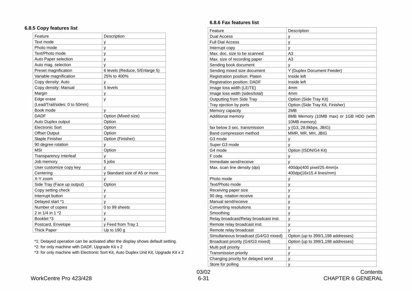
03/02 ContentsWorkCentre Pro 423/428 6-31 CHAPTER 6 GENERAL
6.8.5 Copy features list
Feature DescriptionText mode yPhoto mode yText/Photo mode yAuto Paper selection yAuto mag. selection yPreset magnification 6 levels (Reduce, 5/Enlarge 5)Variable magnification 25% to 400%Copy density: Auto yCopy density: Manual 5 levelsMargin yEdge erase(Lead/Trail/sides: 0 to 50mm)
y
Book mode yDADF Option (Mixed size)Auto Duplex output OptionElectronic Sort OptionOffset Output OptionStaple Finisher Option (Finisher)90 degree rotation yMSI OptionTransparency Interleaf yJob memory 5 jobsUser customize copy key yCentering y Standard size of A5 or moreX-Y zoom ySide Tray (Face up output) OptionCopy setting check yInterrupt button yDelayed start *1 yNumber of copies 0 to 99 sheets2 in 1/4 in 1 *2 yBooklet *3 yPostcard, Envelope y Feed from Tray 1Thick Paper Up to 190 g
*1: Delayed operation can be activated after the display shows default setting.*2: for only machine with DADF, Upgrade Kit x 2*3: for only machine with Electronic Sort Kit, Auto Duplex Unit Kit, Upgrade Kit x 2
6.8.6 Fax features list
Feature DescriptionDual Access yFull Dial Access yInterrupt copy yMax. doc. size to be scanned A3Max. size of recording paper A3Sending book document ySending mixed size document Y (Duplex Document Feeder)Registration position: Platen Inside leftRegistration position: DADF Inside leftImage loss width (LE/TE) 4mmImage loss width (sides/total) 4mmOutputting from Side Tray Option (Side Tray Kit)Tray ejection by ports Option (Side Tray Kit, Finisher)Memory capacity 2MBAdditional memory 8MB Memory (10MB max) or 1GB HDD (with
10MB memory)fax below 3 sec. transmission y (G3, 28.8kbps, JBIG)Band compression method MMR, MR, MH, JBIGG3 mode ySuper G3 mode yG4 mode Option (ISDN/G4 Kit)F code yImmediate send/receive yMax. scan line density (dpi) 400dpi(400 pixel/25.4mm)x
400dpi(16x15.4 lines/mm)Photo mode yText/Photo mode yReceiving paper size y90 deg. rotation receive yManual send/receive yConverting resolutions ySmoothing yRelay broadcast/Relay broadcast inst. yRemote relay broadcast inst. yRemote relay broadcast ySimultaneous broadcast (G4/G3 mixed) Option (up to 399/1,198 addresses)Broadcast priority (G4/G3 mixed) Option (up to 399/1,198 addresses)Multi poll priority yTransmission priority yChanging priority for delayed send yStore for polling y
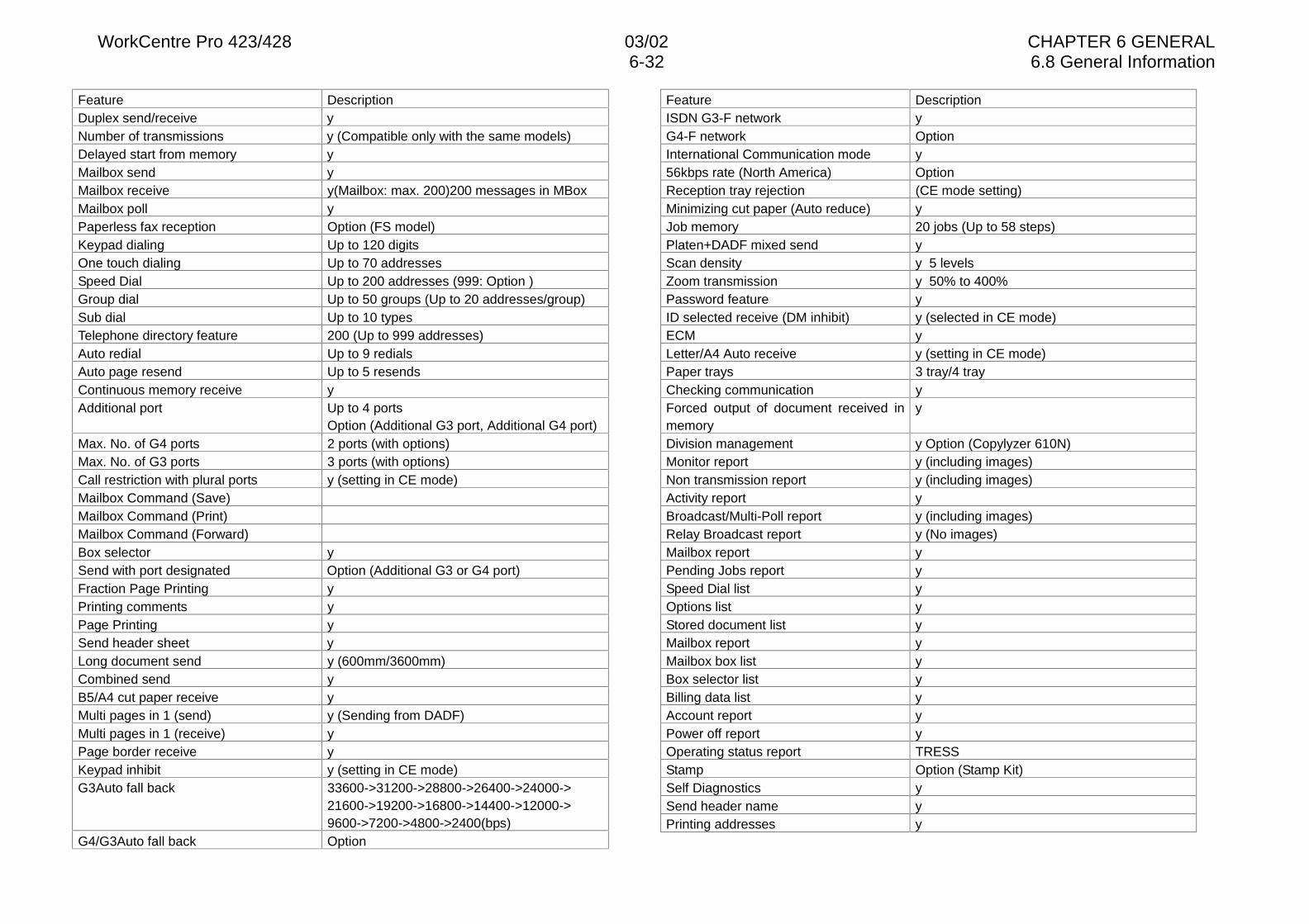
WorkCentre Pro 423/428 03/02 CHAPTER 6 GENERAL6-32 6.8 General Information
Feature DescriptionDuplex send/receive yNumber of transmissions y (Compatible only with the same models)Delayed start from memory yMailbox send yMailbox receive y(Mailbox: max. 200)200 messages in MBoxMailbox poll yPaperless fax reception Option (FS model)Keypad dialing Up to 120 digitsOne touch dialing Up to 70 addressesSpeed Dial Up to 200 addresses (999: Option )Group dial Up to 50 groups (Up to 20 addresses/group)Sub dial Up to 10 typesTelephone directory feature 200 (Up to 999 addresses)Auto redial Up to 9 redialsAuto page resend Up to 5 resendsContinuous memory receive yAdditional port Up to 4 ports
Option (Additional G3 port, Additional G4 port)Max. No. of G4 ports 2 ports (with options)Max. No. of G3 ports 3 ports (with options)Call restriction with plural ports y (setting in CE mode)Mailbox Command (Save)Mailbox Command (Print)Mailbox Command (Forward)Box selector ySend with port designated Option (Additional G3 or G4 port)Fraction Page Printing yPrinting comments yPage Printing ySend header sheet yLong document send y (600mm/3600mm)Combined send yB5/A4 cut paper receive yMulti pages in 1 (send) y (Sending from DADF)Multi pages in 1 (receive) yPage border receive yKeypad inhibit y (setting in CE mode)G3Auto fall back 33600->31200->28800->26400->24000->
21600->19200->16800->14400->12000->9600->7200->4800->2400(bps)
G4/G3Auto fall back Option
Feature DescriptionISDN G3-F network yG4-F network OptionInternational Communication mode y56kbps rate (North America) OptionReception tray rejection (CE mode setting)Minimizing cut paper (Auto reduce) yJob memory 20 jobs (Up to 58 steps)Platen+DADF mixed send yScan density y 5 levelsZoom transmission y 50% to 400%Password feature yID selected receive (DM inhibit) y (selected in CE mode)ECM yLetter/A4 Auto receive y (setting in CE mode)Paper trays 3 tray/4 trayChecking communication yForced output of document received inmemory
y
Division management y Option (Copylyzer 610N)Monitor report y (including images)Non transmission report y (including images)Activity report yBroadcast/Multi-Poll report y (including images)Relay Broadcast report y (No images)Mailbox report yPending Jobs report ySpeed Dial list yOptions list yStored document list yMailbox report yMailbox box list yBox selector list yBilling data list yAccount report yPower off report yOperating status report TRESSStamp Option (Stamp Kit)Self Diagnostics ySend header name yPrinting addresses y
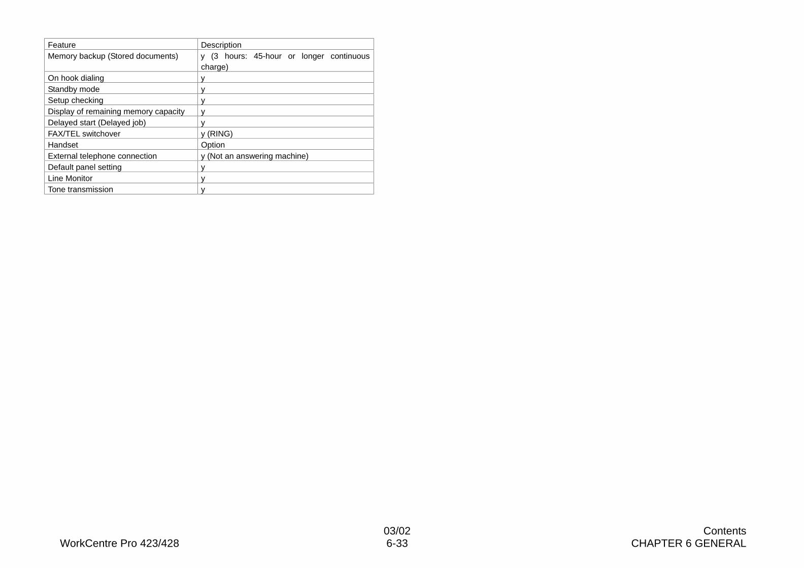
03/02 ContentsWorkCentre Pro 423/428 6-33 CHAPTER 6 GENERAL
Feature DescriptionMemory backup (Stored documents) y (3 hours: 45-hour or longer continuous
charge)On hook dialing yStandby mode ySetup checking yDisplay of remaining memory capacity yDelayed start (Delayed job) yFAX/TEL switchover y (RING)Handset OptionExternal telephone connection y (Not an answering machine)Default panel setting yLine Monitor yTone transmission y
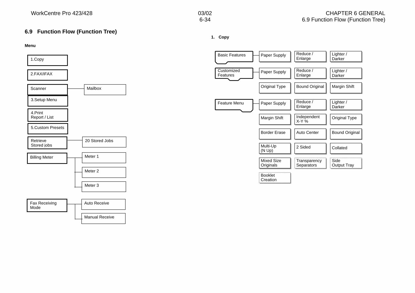
WorkCentre Pro 423/428 03/02 CHAPTER 6 GENERAL6-34 6.9 Function Flow (Function Tree)
6.9 Function Flow (Function Tree)
Menu
1. Copy
Paper SupplyBasic Features
Feature Menu
CustomizedFeatures
Mixed SizeOriginals
Reduce /Enlarge
Lighter /Darker
Paper Supply Reduce /Enlarge
Lighter /Darker
Paper Supply Reduce /Enlarge
Lighter /Darker
Original Type Bound Original Margin Shift
Margin Shift
BookletCreation
Original Type
Border Erase Auto Center Bound Original
2 Sided Collated
TransparencySeparators
IndependentX-Y %
Multi-Up(N Up)
SideOutput Tray
1.Copy
2.FAX/iFAX
Scanner
3.Setup Menu
4.PrintReport / List
5.Custom Presets
RetrieveStored jobs
Billing Meter
Fax ReceivingMode
Mailbox
20 Stored Jobs
Meter 1
Meter 2
Auto Receive
Manual Receive
Meter 3
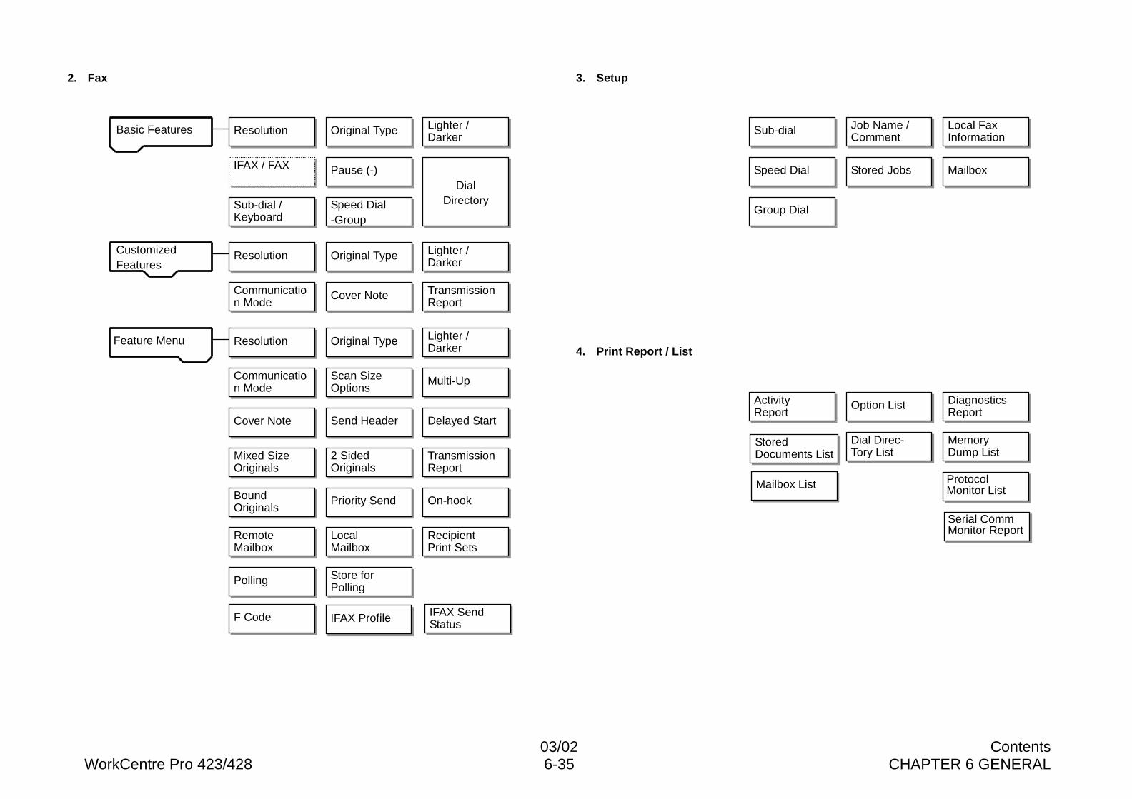
03/02 ContentsWorkCentre Pro 423/428 6-35 CHAPTER 6 GENERAL
2. Fax 3. Setup
4. Print Report / ListFeature Menu
ResolutionBasic Features
CustomizedFeatures
On-hook
Original Type Lighter /Darker
Resolution Original Type Lighter /Darker
Resolution Original Type Lighter /Darker
Communication Mode
Scan SizeOptions
Cover Note
Communication Mode
Multi-Up
Cover Note Send Header Delayed Start
2 SidedOriginals
BoundOriginals
Priority Send
TransmissionReport
Mixed SizeOriginals
IFAX / FAX Pause (-)
Sub-dial /Keyboard
Speed Dial-Group
DialDirectory
TransmissionReport
RemoteMailbox
LocalMailbox
RecipientPrint Sets
Polling Store forPolling
Sub-dial Job Name /Comment
Local FaxInformation
Stored JobsSpeed Dial Mailbox
Group Dial
ActivityReport
Option List DiagnosticsReport
StoredDocuments List
Dial Direc-Tory List
MemoryDump List
ProtocolMonitor List
Serial CommMonitor Report
F Code IFAX Profile IFAX SendStatus
Mailbox List
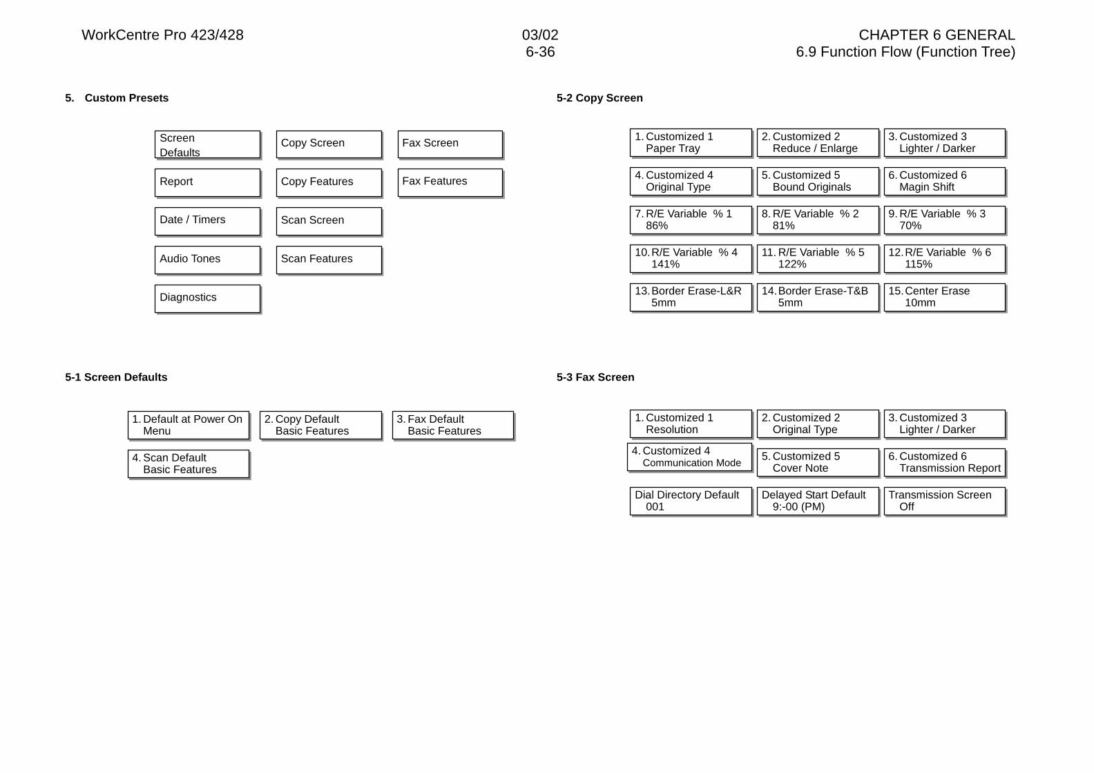
WorkCentre Pro 423/428 03/02 CHAPTER 6 GENERAL6-36 6.9 Function Flow (Function Tree)
5. Custom Presets
5-1 Screen Defaults
5-2 Copy Screen
5-3 Fax Screen
ScreenDefaults
Copy Screen Fax Screen
Report Copy Features Fax Features
Date / Timers Scan Screen
Audio Tones Scan Features
Diagnostics
1. Default at Power OnMenu
2. Copy DefaultBasic Features
3. Fax DefaultBasic Features
4. Scan DefaultBasic Features
1. Customized 1Paper Tray
2. Customized 2Reduce / Enlarge
3. Customized 3Lighter / Darker
4. Customized 4Original Type
5. Customized 5Bound Originals
6. Customized 6Magin Shift
7. R/E Variable % 186%
8. R/E Variable % 281%
9. R/E Variable % 370%
10.R/E Variable % 4141%
11. R/E Variable % 5122%
12.R/E Variable % 6115%
13.Border Erase-L&R5mm
14.Border Erase-T&B5mm
15.Center Erase10mm
1. Customized 1Resolution
2. Customized 2Original Type
3. Customized 3Lighter / Darker
4. Customized 4Communication Mode
5. Customized 5Cover Note
6. Customized 6Transmission Report
Dial Directory Default001
Delayed Start Default9:-00 (PM)
Transmission ScreenOff
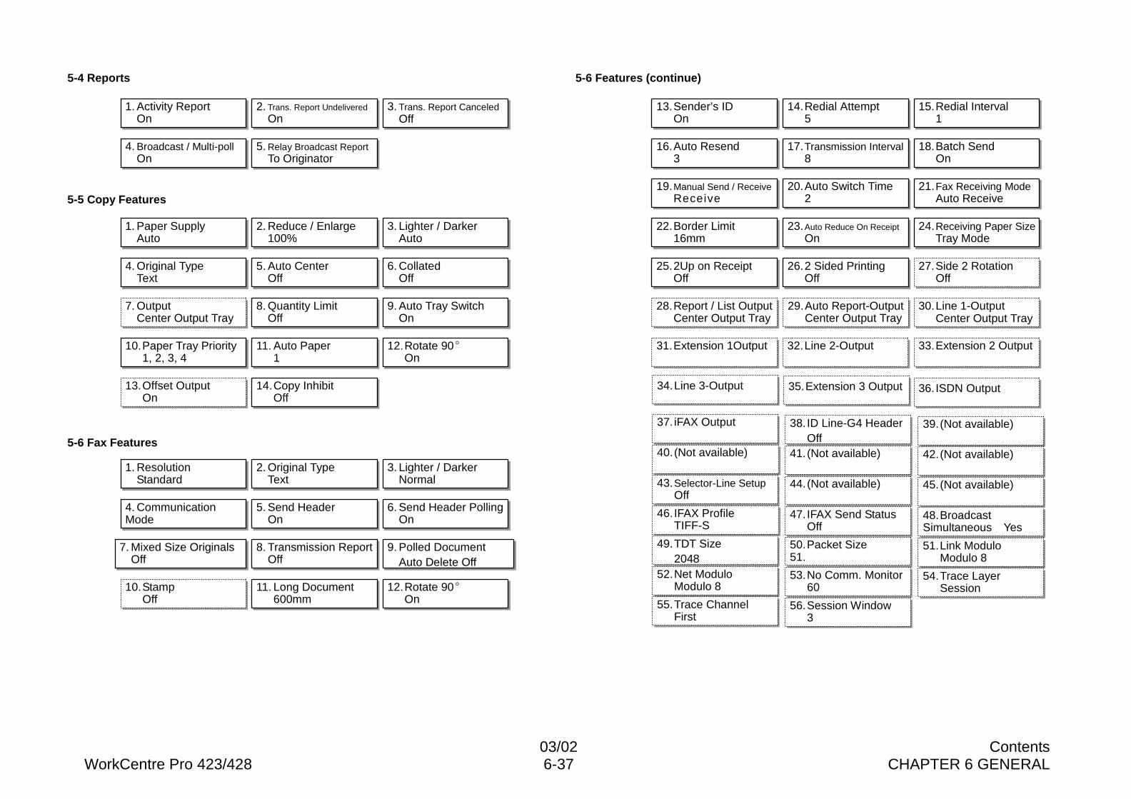
03/02 ContentsWorkCentre Pro 423/428 6-37 CHAPTER 6 GENERAL
5-4 Reports
5-5 Copy Features
5-6 Fax Features
5-6 Features (continue)
1. Activity ReportOn
2. Trans. Report UndeliveredOn
3. Trans. Report CanceledOff
4. Broadcast / Multi-pollOn
5. Relay Broadcast ReportTo Originator
1. Paper SupplyAuto
2. Reduce / Enlarge100%
3. Lighter / DarkerAuto
4. Original TypeText
5. Auto CenterOff
6. CollatedOff
7. OutputCenter Output Tray
8. Quantity LimitOff
9. Auto Tray SwitchOn
10.Paper Tray Priority1, 2, 3, 4
11. Auto Paper1
12.Rotate 90�On
13.Offset OutputOn
14.Copy InhibitOff
1. ResolutionStandard
2. Original TypeText
3. Lighter / DarkerNormal
4. CommunicationMode
5. Send HeaderOn
6. Send Header PollingOn
7. Mixed Size OriginalsOff
8. Transmission ReportOff
9. Polled DocumentAuto Delete Off
10.StampOff
11. Long Document600mm
12.Rotate 90�On
13.Sender’s IDOn
14.Redial Attempt5
15.Redial Interval1
16.Auto Resend3
17.Transmission Interval8
18.Batch SendOn
19.Manual Send / ReceiveReceive
20.Auto Switch Time2
21.Fax Receiving ModeAuto Receive
22.Border Limit16mm
23.Auto Reduce On ReceiptOn
24.Receiving Paper SizeTray Mode
25.2Up on ReceiptOff
26.2 Sided PrintingOff
27.Side 2 RotationOff
28.Report / List OutputCenter Output Tray
29.Auto Report-OutputCenter Output Tray
30. Line 1-OutputCenter Output Tray
31.Extension 1Output 32.Line 2-Output 33.Extension 2 Output
34.Line 3-Output 35.Extension 3 Output 36. ISDN Output
38. ID Line-G4 HeaderOff
48.BroadcastSimultaneous Yes
49.TDT Size2048
50. Packet Size51.
51.Link ModuloModulo 8
52.Net ModuloModulo 8
53.No Comm. Monitor60
54.Trace LayerSession
55.Trace ChannelFirst
56.Session Window3
37. iFAX Output 39.(Not available)
40.(Not available) 42.(Not available)
43. Selector-Line SetupOff
41.(Not available)
45. (Not available)
46. IFAX ProfileTIFF-S
44. (Not available)
47. IFAX Send StatusOff
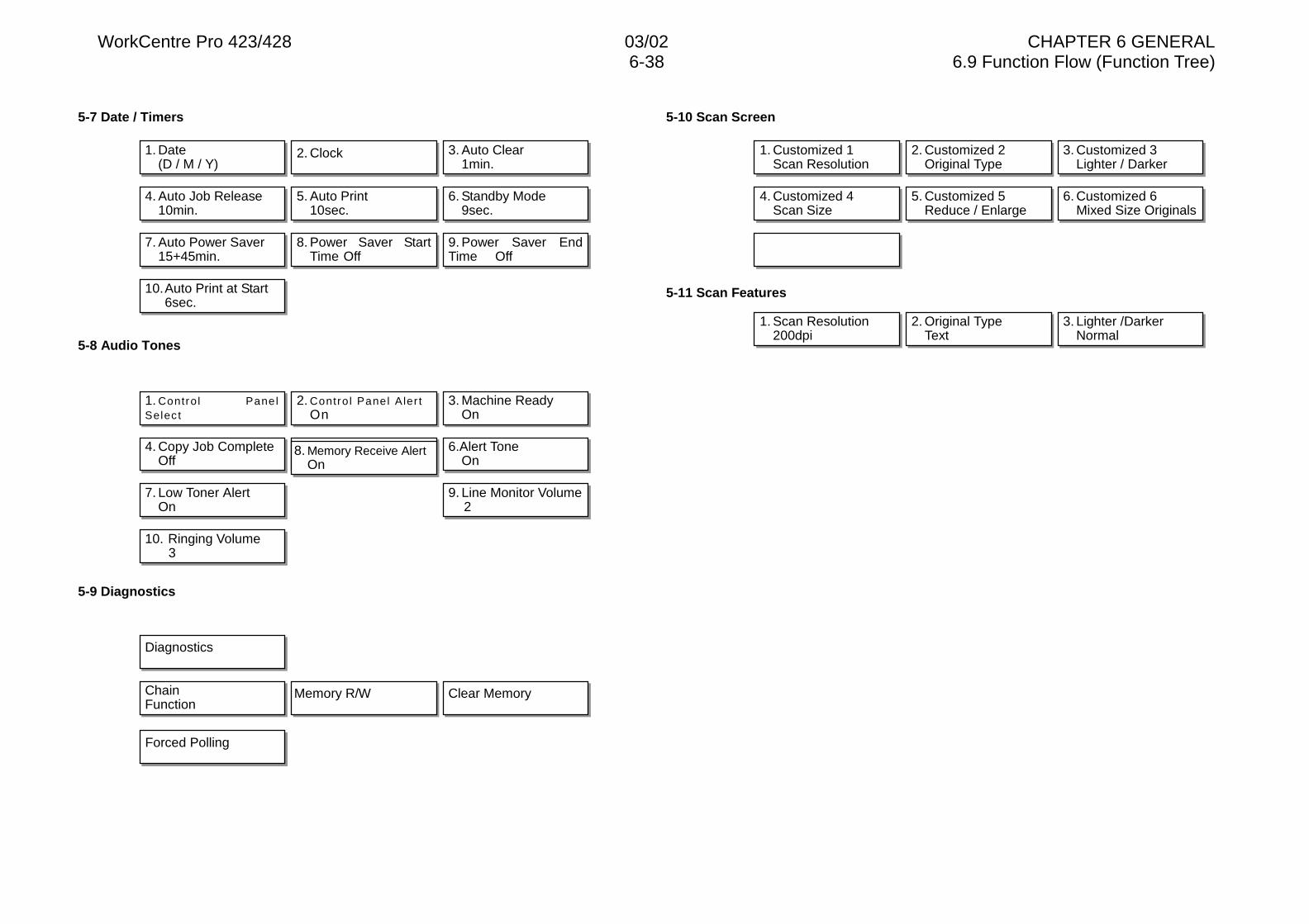
WorkCentre Pro 423/428 03/02 CHAPTER 6 GENERAL6-38 6.9 Function Flow (Function Tree)
5-7 Date / Timers
5-8 Audio Tones
5-9 Diagnostics
5-10 Scan Screen
5-11 Scan Features
1. Date(D / M / Y)
2. Clock 3. Auto Clear1min.
4. Auto Job Release10min.
5. Auto Print10sec.
6. Standby Mode9sec.
7. Auto Power Saver15+45min.
8. Power Saver StartTime Off
9. Power Saver EndTime Off
10.Auto Print at Start6sec.
1. Contro l PanelSelect
2. Contro l Panel Aler tOn
3. Machine ReadyOn
4. Copy Job CompleteOff
5. Job Comple te (Others )
On6.Alert Tone
On
7. Low Toner AlertOn
9. Line Monitor Volume2
10. Ringing Volume3
Diagnostics
ChainFunction
Memory R/W Clear Memory
1. Customized 1Scan Resolution
2. Customized 2Original Type
3. Customized 3Lighter / Darker
4. Customized 4Scan Size
5. Customized 5Reduce / Enlarge
6. Customized 6Mixed Size Originals
1. Scan Resolution200dpi
2. Original TypeText
3. Lighter /DarkerNormal
Forced Polling
8. Memory Receive AlertOn

CHAPTER 7 ELECTRICAL WIRING DIAGRAMS

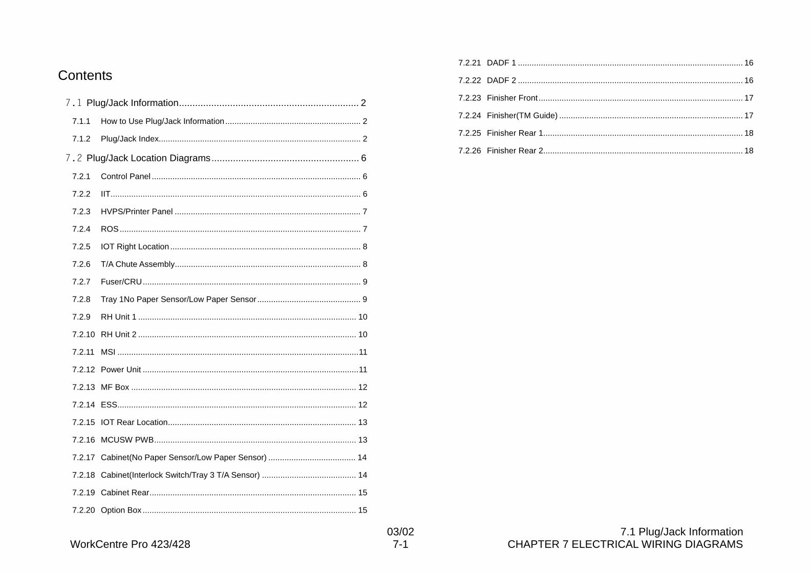
03/02 7.1 Plug/Jack InformationWorkCentre Pro 423/428 7-1 CHAPTER 7 ELECTRICAL WIRING DIAGRAMS
Contents
��� Plug/Jack Information................................................................... 2
7.1.1 How to Use Plug/Jack Information........................................................... 2
7.1.2 Plug/Jack Index........................................................................................ 2
��� Plug/Jack Location Diagrams....................................................... 6
7.2.1 Control Panel ........................................................................................... 6
7.2.2 IIT............................................................................................................. 6
7.2.3 HVPS/Printer Panel ................................................................................. 7
7.2.4 ROS......................................................................................................... 7
7.2.5 IOT Right Location ................................................................................... 8
7.2.6 T/A Chute Assembly................................................................................. 8
7.2.7 Fuser/CRU............................................................................................... 9
7.2.8 Tray 1No Paper Sensor/Low Paper Sensor ............................................. 9
7.2.9 RH Unit 1 ............................................................................................... 10
7.2.10 RH Unit 2 ............................................................................................... 10
7.2.11 MSI .........................................................................................................11
7.2.12 Power Unit ..............................................................................................11
7.2.13 MF Box .................................................................................................. 12
7.2.14 ESS........................................................................................................ 12
7.2.15 IOT Rear Location.................................................................................. 13
7.2.16 MCUSW PWB........................................................................................ 13
7.2.17 Cabinet(No Paper Sensor/Low Paper Sensor) ...................................... 14
7.2.18 Cabinet(Interlock Switch/Tray 3 T/A Sensor) ......................................... 14
7.2.19 Cabinet Rear.......................................................................................... 15
7.2.20 Option Box ............................................................................................. 15
7.2.21 DADF 1 .................................................................................................. 16
7.2.22 DADF 2 .................................................................................................. 16
7.2.23 Finisher Front ......................................................................................... 17
7.2.24 Finisher(TM Guide) ................................................................................ 17
7.2.25 Finisher Rear 1....................................................................................... 18
7.2.26 Finisher Rear 2....................................................................................... 18
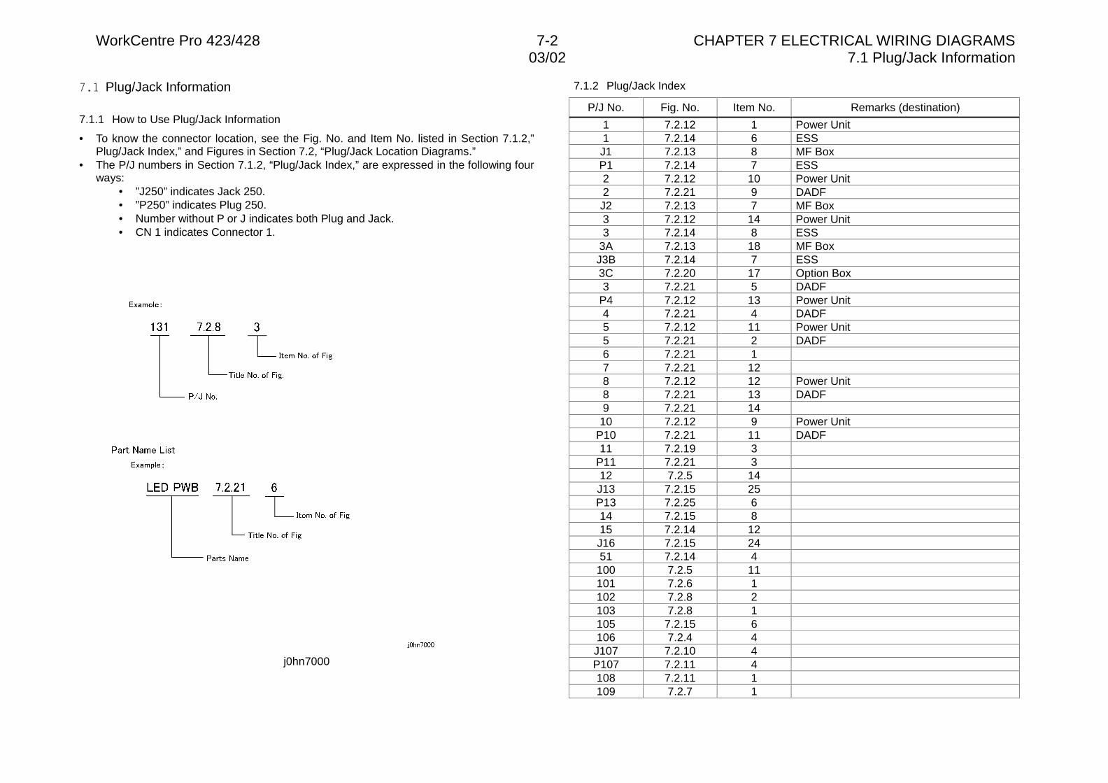
WorkCentre Pro 423/428 7-2 CHAPTER 7 ELECTRICAL WIRING DIAGRAMS03/02 7.1 Plug/Jack Information
��� Plug/Jack Information
7.1.1 How to Use Plug/Jack Information
• To know the connector location, see the Fig. No. and Item No. listed in Section 7.1.2,”Plug/Jack Index,” and Figures in Section 7.2, “Plug/Jack Location Diagrams.”
• The P/J numbers in Section 7.1.2, “Plug/Jack Index,” are expressed in the following fourways:
• ”J250” indicates Jack 250.• ”P250” indicates Plug 250.• Number without P or J indicates both Plug and Jack.• CN 1 indicates Connector 1.
j0hn7000
7.1.2 Plug/Jack Index
P/J No. Fig. No. Item No. Remarks (destination)
1 7.2.12 1 Power Unit1 7.2.14 6 ESSJ1 7.2.13 8 MF BoxP1 7.2.14 7 ESS2 7.2.12 10 Power Unit2 7.2.21 9 DADFJ2 7.2.13 7 MF Box3 7.2.12 14 Power Unit3 7.2.14 8 ESS
3A 7.2.13 18 MF BoxJ3B 7.2.14 7 ESS3C 7.2.20 17 Option Box3 7.2.21 5 DADF
P4 7.2.12 13 Power Unit4 7.2.21 4 DADF5 7.2.12 11 Power Unit5 7.2.21 2 DADF6 7.2.21 17 7.2.21 128 7.2.12 12 Power Unit8 7.2.21 13 DADF9 7.2.21 14
10 7.2.12 9 Power UnitP10 7.2.21 11 DADF11 7.2.19 3
P11 7.2.21 312 7.2.5 14J13 7.2.15 25P13 7.2.25 614 7.2.15 815 7.2.14 12J16 7.2.15 2451 7.2.14 4
100 7.2.5 11101 7.2.6 1102 7.2.8 2103 7.2.8 1105 7.2.15 6106 7.2.4 4J107 7.2.10 4P107 7.2.11 4108 7.2.11 1109 7.2.7 1
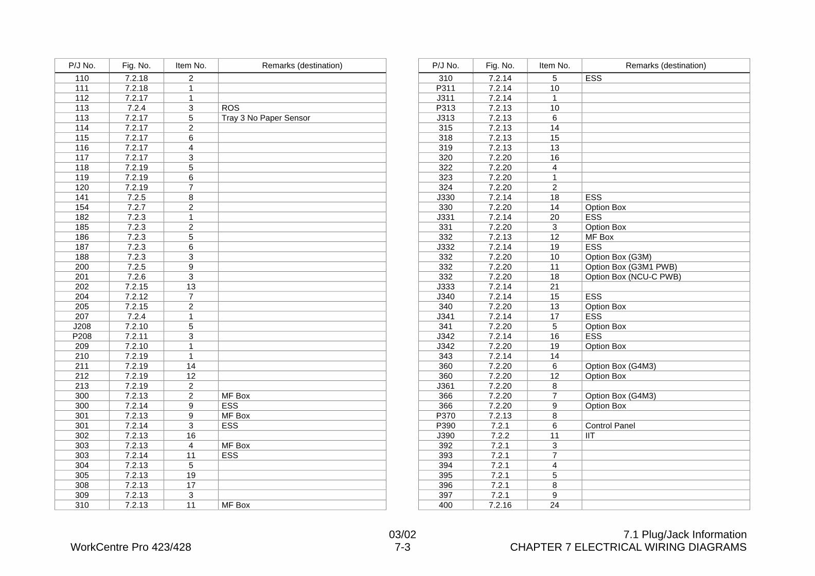
03/02 7.1 Plug/Jack InformationWorkCentre Pro 423/428 7-3 CHAPTER 7 ELECTRICAL WIRING DIAGRAMS
P/J No. Fig. No. Item No. Remarks (destination)
110 7.2.18 2111 7.2.18 1112 7.2.17 1113 7.2.4 3 ROS113 7.2.17 5 Tray 3 No Paper Sensor114 7.2.17 2115 7.2.17 6116 7.2.17 4117 7.2.17 3118 7.2.19 5119 7.2.19 6120 7.2.19 7141 7.2.5 8154 7.2.7 2182 7.2.3 1185 7.2.3 2186 7.2.3 5187 7.2.3 6188 7.2.3 3200 7.2.5 9201 7.2.6 3202 7.2.15 13204 7.2.12 7205 7.2.15 2207 7.2.4 1J208 7.2.10 5P208 7.2.11 3209 7.2.10 1210 7.2.19 1211 7.2.19 14212 7.2.19 12213 7.2.19 2300 7.2.13 2 MF Box300 7.2.14 9 ESS301 7.2.13 9 MF Box301 7.2.14 3 ESS302 7.2.13 16303 7.2.13 4 MF Box303 7.2.14 11 ESS304 7.2.13 5305 7.2.13 19308 7.2.13 17309 7.2.13 3310 7.2.13 11 MF Box
P/J No. Fig. No. Item No. Remarks (destination)
310 7.2.14 5 ESSP311 7.2.14 10J311 7.2.14 1P313 7.2.13 10J313 7.2.13 6315 7.2.13 14318 7.2.13 15319 7.2.13 13320 7.2.20 16322 7.2.20 4323 7.2.20 1324 7.2.20 2J330 7.2.14 18 ESS330 7.2.20 14 Option BoxJ331 7.2.14 20 ESS331 7.2.20 3 Option Box332 7.2.13 12 MF BoxJ332 7.2.14 19 ESS332 7.2.20 10 Option Box (G3M)332 7.2.20 11 Option Box (G3M1 PWB)332 7.2.20 18 Option Box (NCU-C PWB)J333 7.2.14 21J340 7.2.14 15 ESS340 7.2.20 13 Option BoxJ341 7.2.14 17 ESS341 7.2.20 5 Option BoxJ342 7.2.14 16 ESSJ342 7.2.20 19 Option Box343 7.2.14 14360 7.2.20 6 Option Box (G4M3)360 7.2.20 12 Option BoxJ361 7.2.20 8366 7.2.20 7 Option Box (G4M3)366 7.2.20 9 Option Box
P370 7.2.13 8P390 7.2.1 6 Control PanelJ390 7.2.2 11 IIT392 7.2.1 3393 7.2.1 7394 7.2.1 4395 7.2.1 5396 7.2.1 8397 7.2.1 9400 7.2.16 24
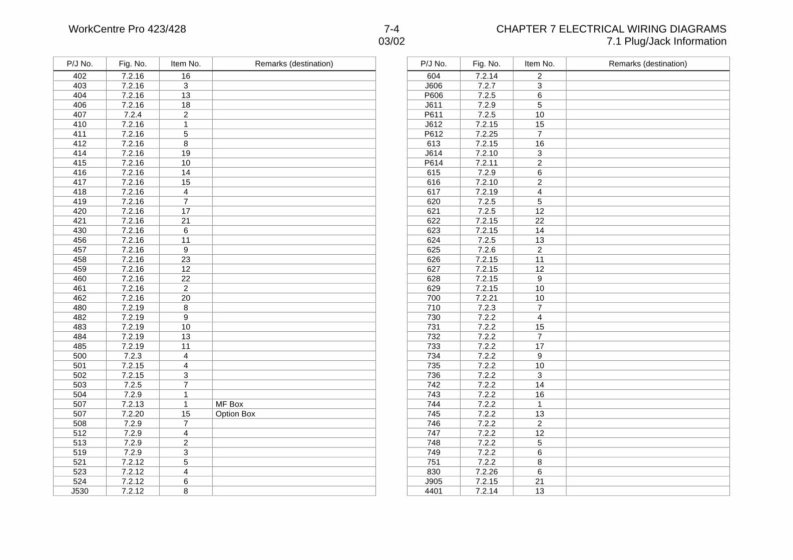
WorkCentre Pro 423/428 7-4 CHAPTER 7 ELECTRICAL WIRING DIAGRAMS03/02 7.1 Plug/Jack Information
P/J No. Fig. No. Item No. Remarks (destination)
402 7.2.16 16403 7.2.16 3404 7.2.16 13406 7.2.16 18407 7.2.4 2410 7.2.16 1411 7.2.16 5412 7.2.16 8414 7.2.16 19415 7.2.16 10416 7.2.16 14417 7.2.16 15418 7.2.16 4419 7.2.16 7420 7.2.16 17421 7.2.16 21430 7.2.16 6456 7.2.16 11457 7.2.16 9458 7.2.16 23459 7.2.16 12460 7.2.16 22461 7.2.16 2462 7.2.16 20480 7.2.19 8482 7.2.19 9483 7.2.19 10484 7.2.19 13485 7.2.19 11500 7.2.3 4501 7.2.15 4502 7.2.15 3503 7.2.5 7504 7.2.9 1507 7.2.13 1 MF Box507 7.2.20 15 Option Box508 7.2.9 7512 7.2.9 4513 7.2.9 2519 7.2.9 3521 7.2.12 5523 7.2.12 4524 7.2.12 6J530 7.2.12 8
P/J No. Fig. No. Item No. Remarks (destination)
604 7.2.14 2J606 7.2.7 3P606 7.2.5 6J611 7.2.9 5P611 7.2.5 10J612 7.2.15 15P612 7.2.25 7613 7.2.15 16J614 7.2.10 3P614 7.2.11 2615 7.2.9 6616 7.2.10 2617 7.2.19 4620 7.2.5 5621 7.2.5 12622 7.2.15 22623 7.2.15 14624 7.2.5 13625 7.2.6 2626 7.2.15 11627 7.2.15 12628 7.2.15 9629 7.2.15 10700 7.2.21 10710 7.2.3 7730 7.2.2 4731 7.2.2 15732 7.2.2 7733 7.2.2 17734 7.2.2 9735 7.2.2 10736 7.2.2 3742 7.2.2 14743 7.2.2 16744 7.2.2 1745 7.2.2 13746 7.2.2 2747 7.2.2 12748 7.2.2 5749 7.2.2 6751 7.2.2 8830 7.2.26 6J905 7.2.15 214401 7.2.14 13
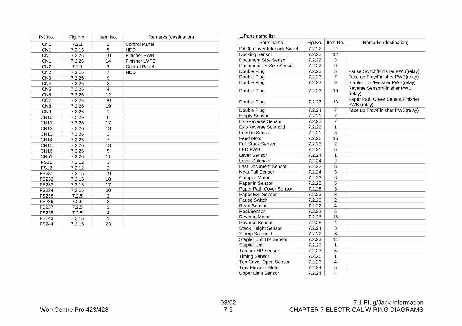
03/02 7.1 Plug/Jack InformationWorkCentre Pro 423/428 7-5 CHAPTER 7 ELECTRICAL WIRING DIAGRAMS
P/J No. Fig. No. Item No. Remarks (destination)
CN1 7.2.1 1 Control PanelCN1 7.2.15 5 HDDCN1 7.2.26 10 Finisher PWBCN1 7.2.26 14 Finisher LVPSCN2 7.2.1 2 Control PanelCN2 7.2.15 7 HDDCN3 7.2.26 9CN4 7.2.26 3CN5 7.2.26 4CN6 7.2.26 12CN7 7.2.26 20CN8 7.2.26 19CN9 7.2.26 1
CN10 7.2.26 8CN11 7.2.26 17CN12 7.2.26 18CN13 7.2.26 2CN14 7.2.26 7CN15 7.2.26 13CN16 7.2.26 5CN51 7.2.26 11FS11 7.2.12 3FS12 7.2.12 2
FS231 7.2.15 19FS232 7.2.15 18FS233 7.2.15 17FS234 7.2.15 20FS235 7.2.5 2FS236 7.2.5 3FS237 7.2.5 1FS238 7.2.5 4FS243 7.2.15 1FS244 7.2.15 23
�Parts name listParts name Fig.No. Item No. Remarks (destination)
DADF Cover Interlock Switch 7.2.22 2Docking Sensor 7.2.23 12Document Size Sensor 7.2.22 3Document TE Size Sensor 7.2.22 9Double Plug 7.2.23 3 Pause Switch/Finisher PWB(relay)Double Plug 7.2.23 7 Face up Tray/Finisher PWB(relay)Double Plug 7.2.23 9 Stapler Unit/Finisher PWB(relay)
Double Plug 7.2.23 10Reverse Sensor/Finisher PWB(relay)
Double Plug 7.2.23 13Paper Path Cover Sensor/FinisherPWB (relay)
Double Plug 7.2.24 7 Face up Tray/Finisher PWB(relay)Empty Sensor 7.2.21 7Exit/Reverse Sensor 7.2.22 7Exit/Reverse Solenoid 7.2.22 1Feed in Sensor 7.2.21 8Feed Motor 7.2.26 15Full Stack Sensor 7.2.25 2LED PWB 7.2.21 6Lever Sensor 7.2.24 1Lever Solenoid 7.2.24 2Last Document Sensor 7.2.22 8Near Full Sensor 7.2.24 5Compile Motor 7.2.23 6Paper in Sensor 7.2.25 5Paper Path Cover Sensor 7.2.25 3Paper Exit Sensor 7.2.23 8Pause Switch 7.2.23 2Read Sensor 7.2.22 4Regi.Sensor 7.2.22 5Reverse Motor 7.2.26 16Reverse Sensor 7.2.25 4Stack Height Sensor 7.2.24 3Stamp Solenoid 7.2.22 6Stapler Unit HP Sensor 7.2.23 11Stepler Unit 7.2.23 1Tamper HP Sensor 7.2.23 5Timing Sensor 7.2.25 1Top Cover Open Sensor 7.2.23 4Tray Elevator Motor 7.2.24 6Upper Limit Sensor 7.2.24 4
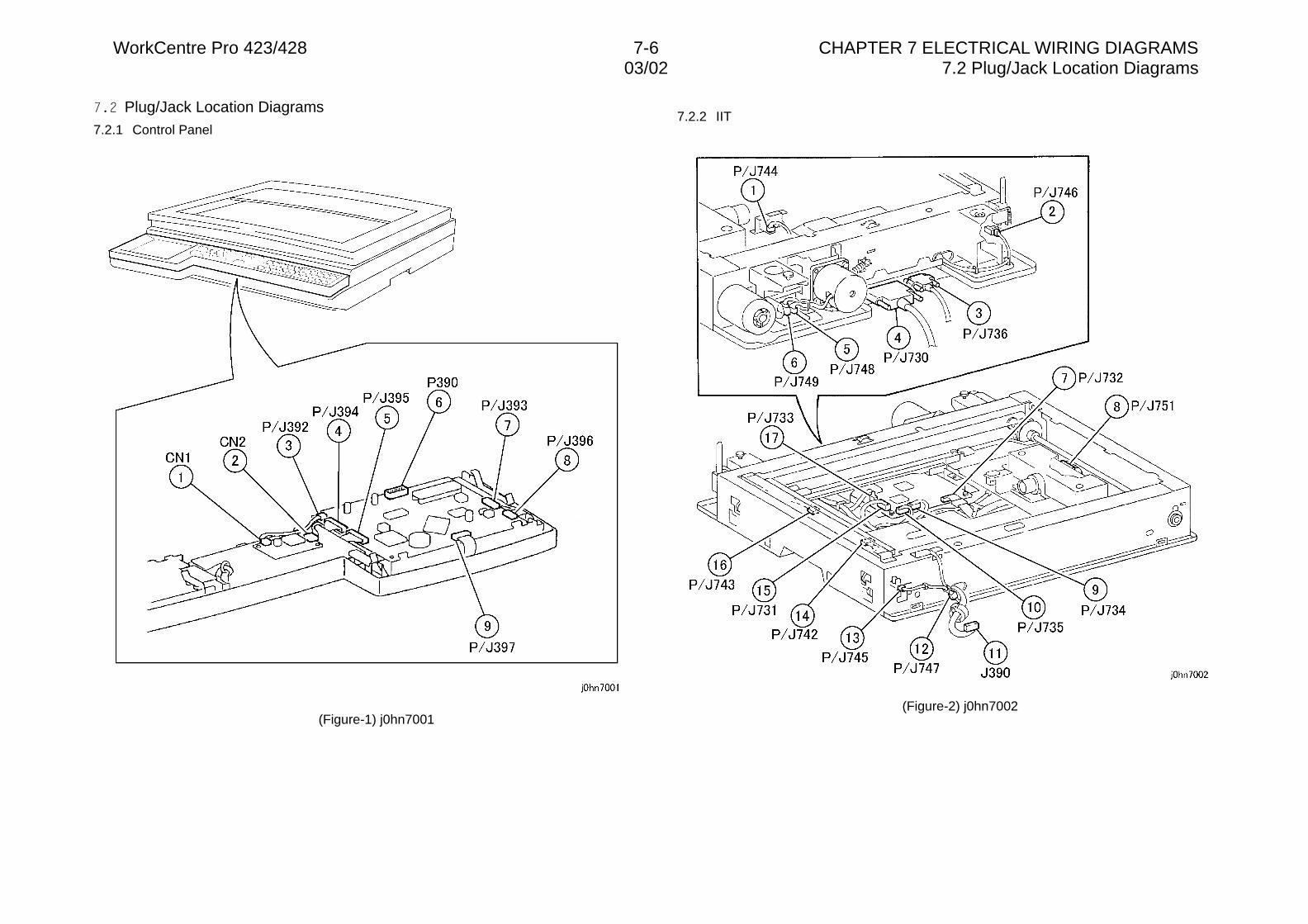
WorkCentre Pro 423/428 7-6 CHAPTER 7 ELECTRICAL WIRING DIAGRAMS03/02 7.2 Plug/Jack Location Diagrams
��� Plug/Jack Location Diagrams7.2.1 Control Panel
(Figure-1) j0hn7001
7.2.2 IIT
(Figure-2) j0hn7002
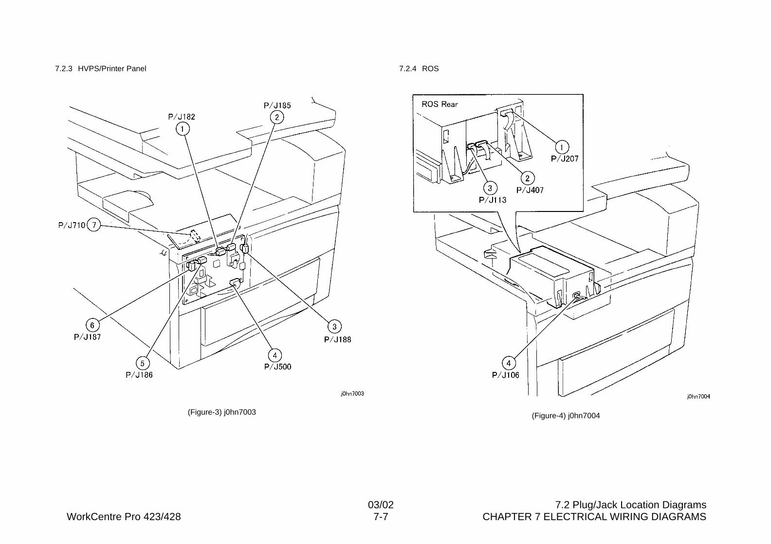
03/02 7.2 Plug/Jack Location DiagramsWorkCentre Pro 423/428 7-7 CHAPTER 7 ELECTRICAL WIRING DIAGRAMS
7.2.3 HVPS/Printer Panel
(Figure-3) j0hn7003
7.2.4 ROS
(Figure-4) j0hn7004
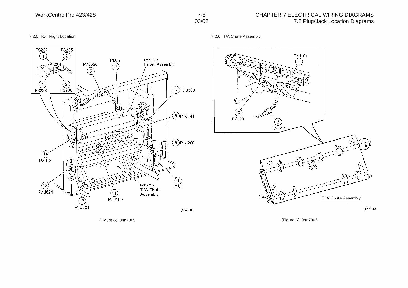
WorkCentre Pro 423/428 7-8 CHAPTER 7 ELECTRICAL WIRING DIAGRAMS03/02 7.2 Plug/Jack Location Diagrams
7.2.5 IOT Right Location
(Figure-5) j0hn7005
7.2.6 T/A Chute Assembly
(Figure-6) j0hn7006
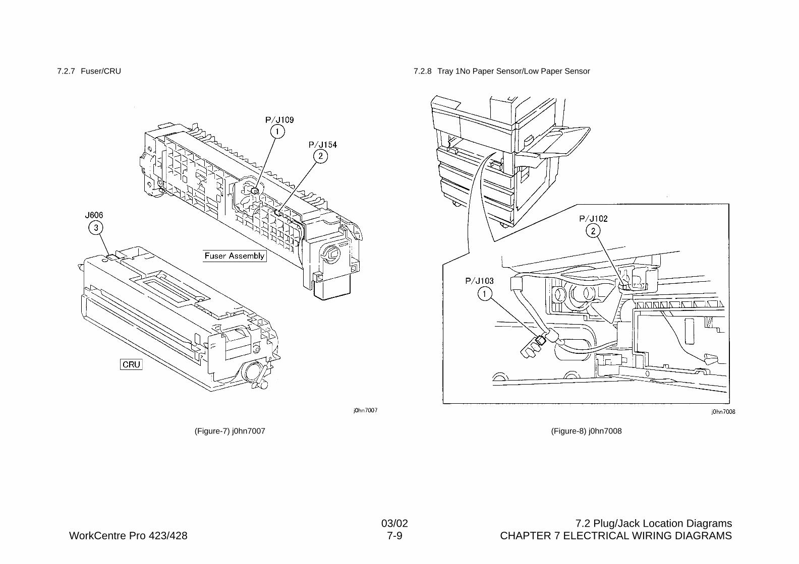
03/02 7.2 Plug/Jack Location DiagramsWorkCentre Pro 423/428 7-9 CHAPTER 7 ELECTRICAL WIRING DIAGRAMS
7.2.7 Fuser/CRU
(Figure-7) j0hn7007
7.2.8 Tray 1No Paper Sensor/Low Paper Sensor
(Figure-8) j0hn7008
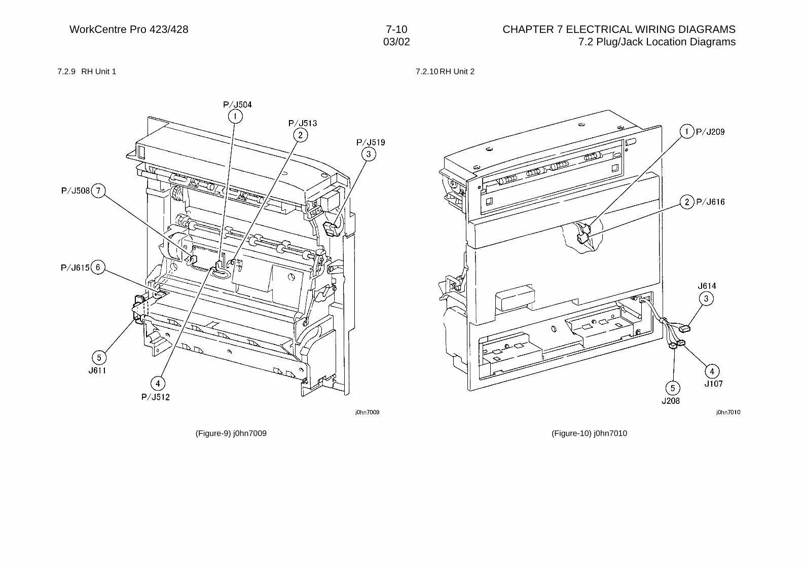
WorkCentre Pro 423/428 7-10 CHAPTER 7 ELECTRICAL WIRING DIAGRAMS03/02 7.2 Plug/Jack Location Diagrams
7.2.9 RH Unit 1
(Figure-9) j0hn7009
7.2.10 RH Unit 2
(Figure-10) j0hn7010
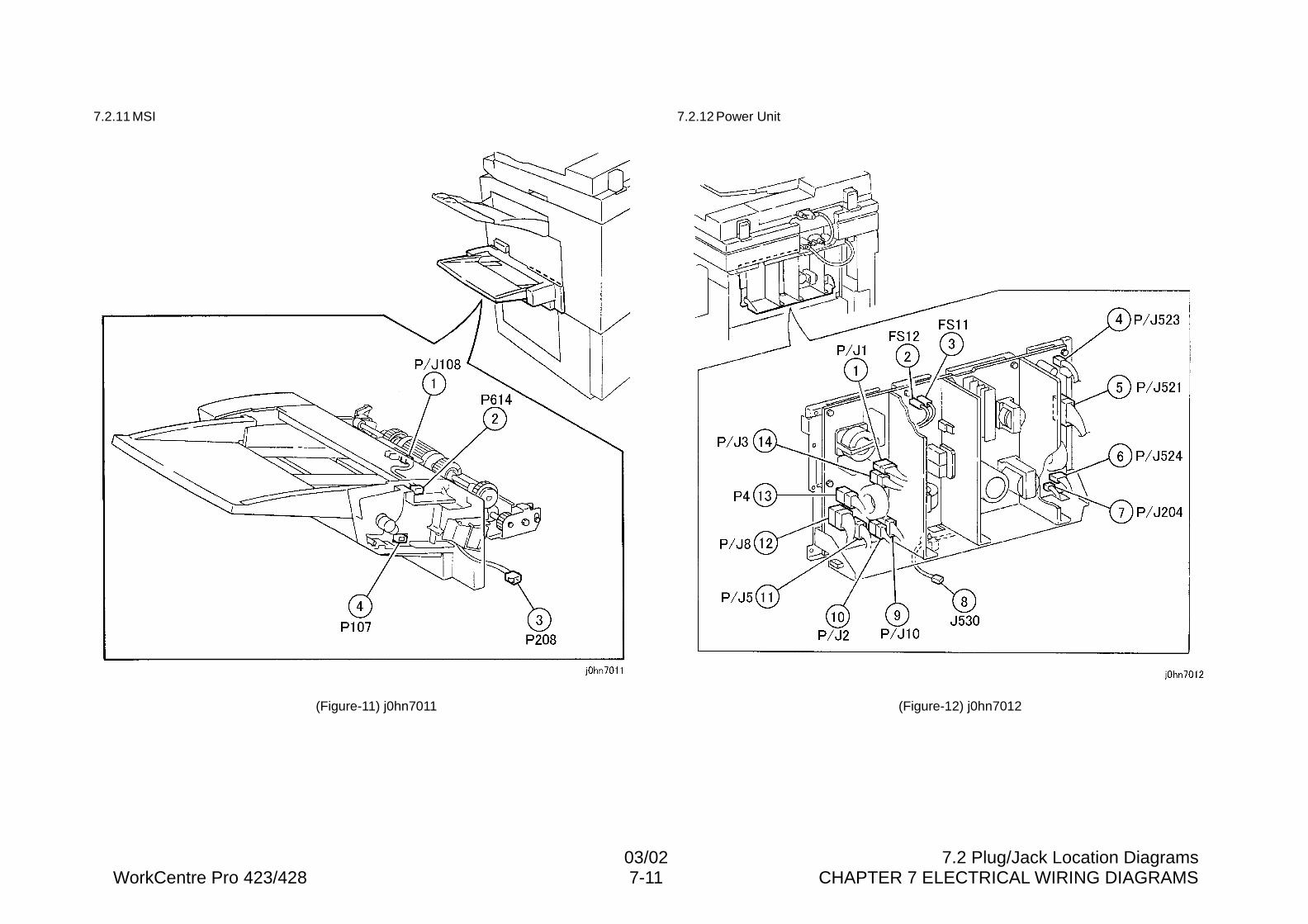
03/02 7.2 Plug/Jack Location DiagramsWorkCentre Pro 423/428 7-11 CHAPTER 7 ELECTRICAL WIRING DIAGRAMS
7.2.11 MSI
(Figure-11) j0hn7011
7.2.12 Power Unit
(Figure-12) j0hn7012
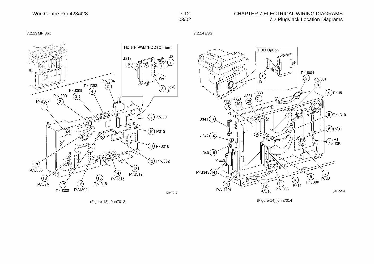
WorkCentre Pro 423/428 7-12 CHAPTER 7 ELECTRICAL WIRING DIAGRAMS03/02 7.2 Plug/Jack Location Diagrams
7.2.13 MF Box
(Figure-13) j0hn7013
7.2.14 ESS
(Figure-14) j0hn7014
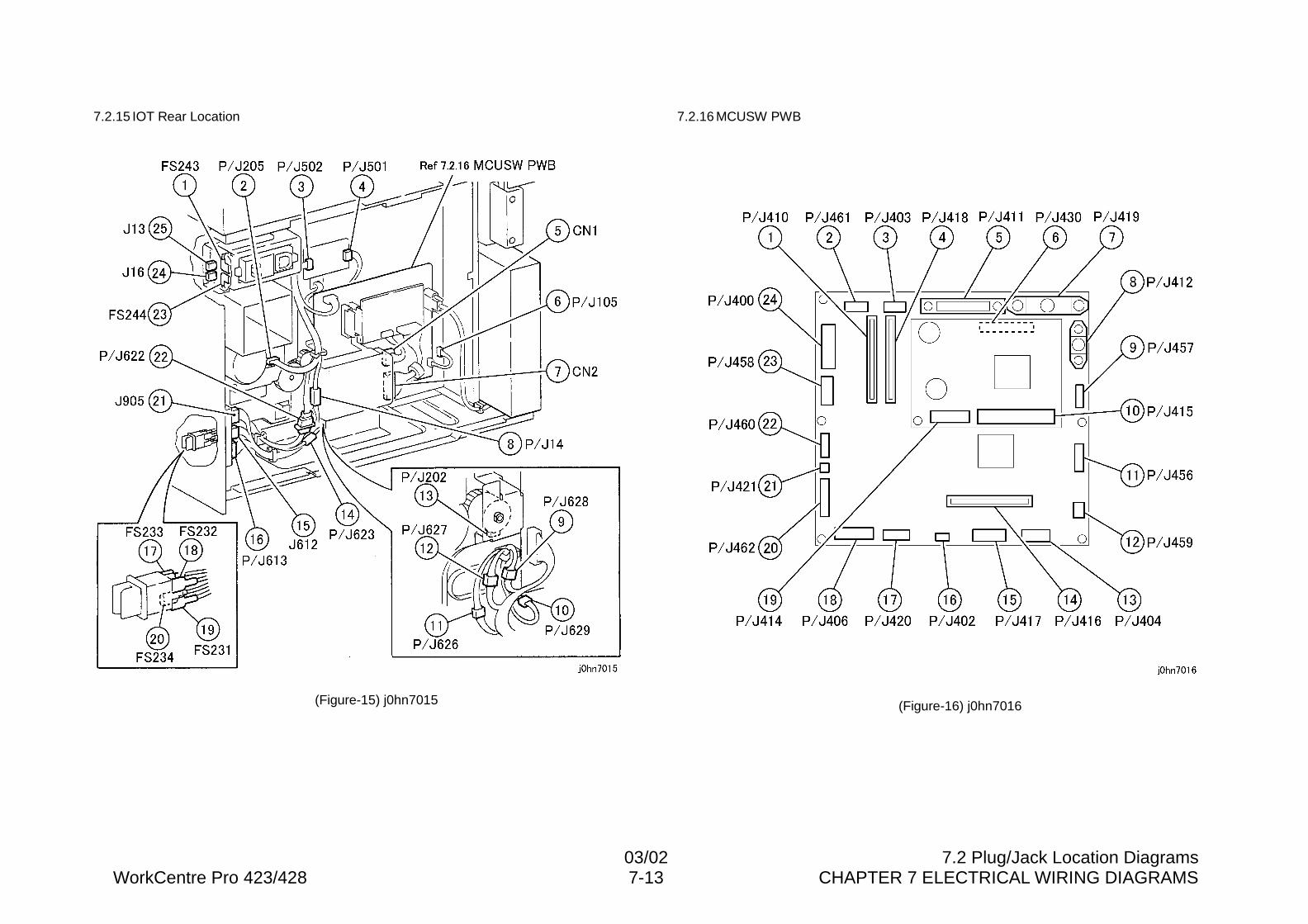
03/02 7.2 Plug/Jack Location DiagramsWorkCentre Pro 423/428 7-13 CHAPTER 7 ELECTRICAL WIRING DIAGRAMS
7.2.15 IOT Rear Location
(Figure-15) j0hn7015
7.2.16 MCUSW PWB
(Figure-16) j0hn7016
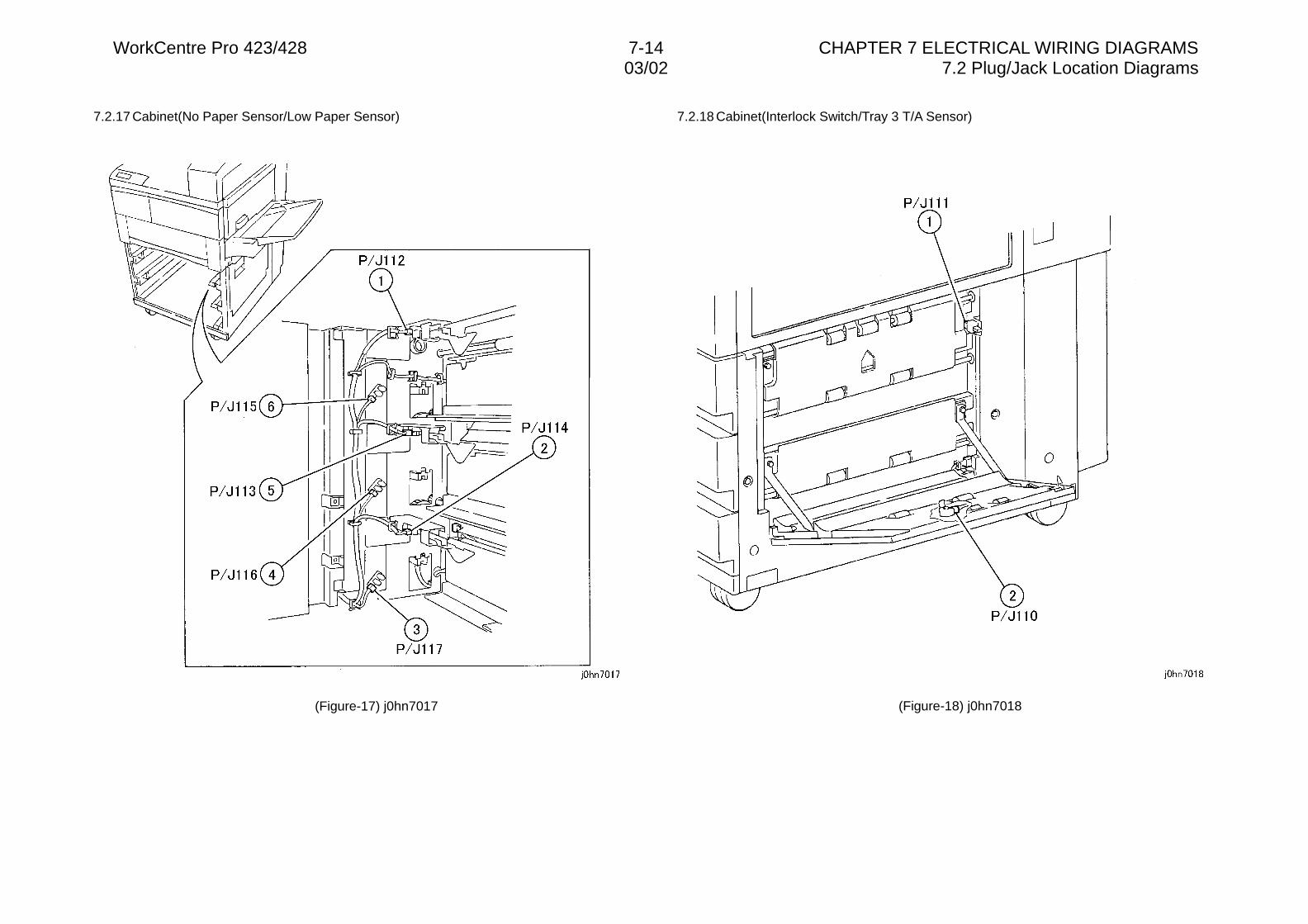
WorkCentre Pro 423/428 7-14 CHAPTER 7 ELECTRICAL WIRING DIAGRAMS03/02 7.2 Plug/Jack Location Diagrams
7.2.17 Cabinet(No Paper Sensor/Low Paper Sensor)
(Figure-17) j0hn7017
7.2.18 Cabinet(Interlock Switch/Tray 3 T/A Sensor)
(Figure-18) j0hn7018
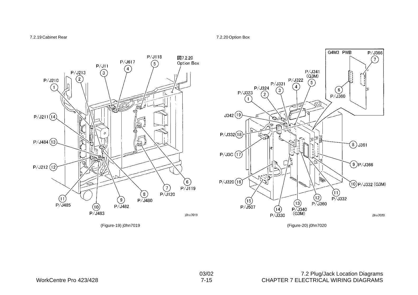
03/02 7.2 Plug/Jack Location DiagramsWorkCentre Pro 423/428 7-15 CHAPTER 7 ELECTRICAL WIRING DIAGRAMS
7.2.19 Cabinet Rear
(Figure-19) j0hn7019
7.2.20 Option Box
(Figure-20) j0hn7020
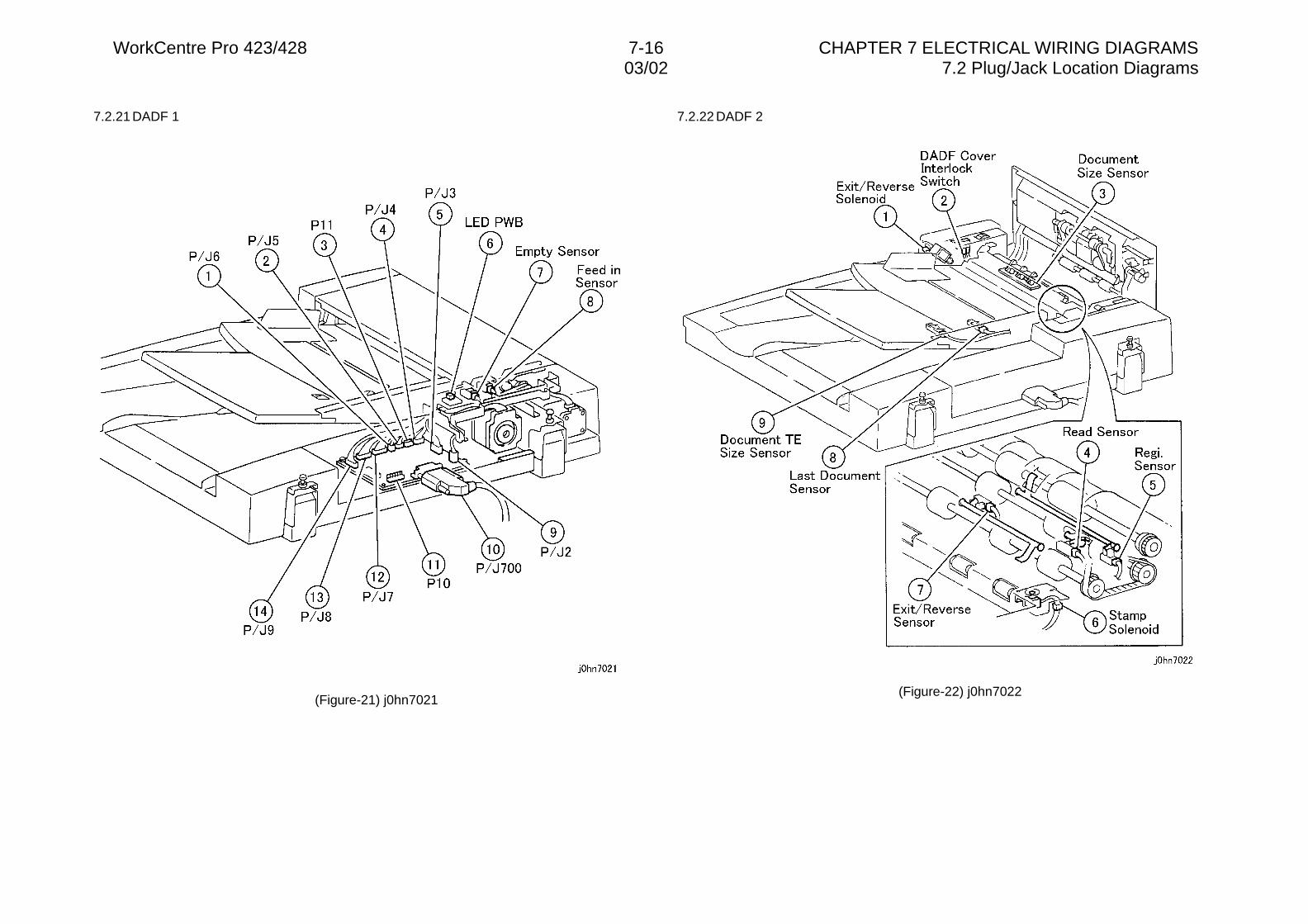
WorkCentre Pro 423/428 7-16 CHAPTER 7 ELECTRICAL WIRING DIAGRAMS03/02 7.2 Plug/Jack Location Diagrams
7.2.21 DADF 1
(Figure-21) j0hn7021
7.2.22 DADF 2
(Figure-22) j0hn7022
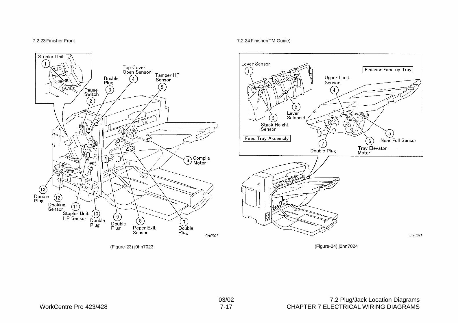
03/02 7.2 Plug/Jack Location DiagramsWorkCentre Pro 423/428 7-17 CHAPTER 7 ELECTRICAL WIRING DIAGRAMS
7.2.23 Finisher Front
(Figure-23) j0hn7023
7.2.24 Finisher(TM Guide)
(Figure-24) j0hn7024
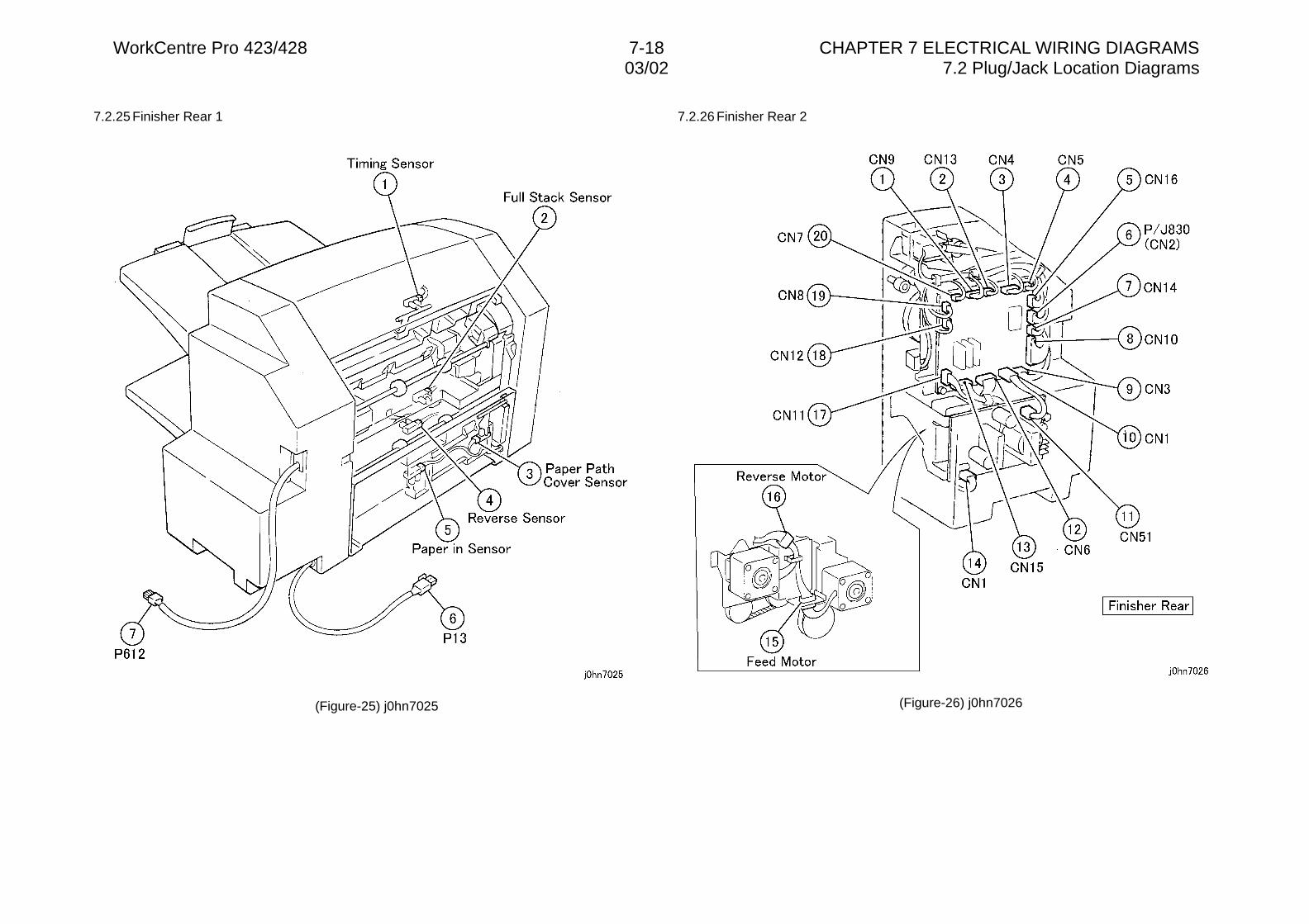
WorkCentre Pro 423/428 7-18 CHAPTER 7 ELECTRICAL WIRING DIAGRAMS03/02 7.2 Plug/Jack Location Diagrams
7.2.25 Finisher Rear 1
(Figure-25) j0hn7025
7.2.26 Finisher Rear 2
(Figure-26) j0hn7026

CHAPTER 8 ACCESSORIES

03/02 ContentsWorkCentre Pro 423/426 8-1 CHAPTER 8 ACCESSORIES
Contents8.1 Additional Tray Kit..................................................................................2
8.1.1 Product Code ......................................................................................................28.1.2 Installation Procedure .........................................................................................2
8.2 Upgrade Kit A(4MB) FX Only .................................................................48.2.1 Product Outline ...................................................................................................48.2.2 Product Code ......................................................................................................48.2.3 Installation Procedure .........................................................................................4
8.3 Electronic Sort Kit ..................................................................................68.3.1 Product Outline ...................................................................................................68.3.2 Product Code ......................................................................................................68.3.3 Installation Procedure .........................................................................................6
8.4 Offset Output Kit ....................................................................................88.4.1 Product Outline ...................................................................................................88.4.2 Product Code......................................................................................................88.4.3 Installation Procedure .........................................................................................8
8.5 MSI Kit ................................................................................................. 118.5.1 Product Code.................................................................................................... 118.5.2 Installation Procedure ....................................................................................... 11
8.6 Duplex Unit Kit .....................................................................................138.6.1 Product Outline .................................................................................................138.6.2 Product Code....................................................................................................138.6.3 Installation Procedure .......................................................................................13
8.7 Side Tray Kit ........................................................................................158.7.1 Product Outline .................................................................................................158.7.2 Product Code....................................................................................................158.7.3 Installation Procedure .......................................................................................15
8.8 Stapler Finisher....................................................................................178.8.1 Product Outline .................................................................................................178.8.2 Product Code....................................................................................................178.8.3 Installation Procedure .......................................................................................17
8.9 English Kit............................................................................................228.9.1 Product Code....................................................................................................228.9.2 Installation Procedure .......................................................................................22
8.10 FAX Unit ...........................................................................................238.10.1 Product Outline ...............................................................................................238.10.2 Product Code ..................................................................................................238.10.3 Installation Procedure .....................................................................................23
8.11 Speed Dial Expansion Kit..................................................................288.11.1 Product Outline ...............................................................................................288.11.2 Product Code ..................................................................................................288.11.3 Installation Procedure .....................................................................................28
8.12 G3 Port ............................................................................................. 298.12.1 Product Outline ............................................................................................... 298.12.2 Product Code.................................................................................................. 298.12.3 Installation Procedure ..................................................................................... 29
8.13 ISDN/G4 Kit ...................................................................................... 328.13.1 Product Outline ............................................................................................... 328.13.2 Product Code.................................................................................................. 328.13.3 Installation Procedure ..................................................................................... 32
8.14 G4 Port ............................................................................................. 358.14.1 Product Code.................................................................................................. 358.14.2 Installation Procedure ..................................................................................... 35
8.15 Line/Ext Switching Kit ....................................................................... 368.15.1 Product Outline ............................................................................................... 368.15.2 Product Code.................................................................................................. 368.15.3 Installation Procedure ..................................................................................... 36
8.16 Fax Hard Disk Kit.............................................................................. 388.16.1 Product Outline ............................................................................................... 388.16.2 Product Code.................................................................................................. 388.16.3 Installation Procedure ..................................................................................... 38
8.17 8MB Memory .................................................................................... 408.17.1 Product Outline ............................................................................................... 408.17.2 Product Code.................................................................................................. 408.17.3 Installation Procedure ..................................................................................... 40
8.18 Printer Kit.......................................................................................... 428.18.1 Product Code.................................................................................................. 428.18.2 Installation Procedure ..................................................................................... 42
8.19 Internet FAX...................................................................................... 468.19.1 Product Outline ............................................................................................... 468.19.2 Product Code.................................................................................................. 468.19.3 Installation Procedure ..................................................................................... 46
8.20 Token Ring........................................................................................ 488.20.1 Product Outline ............................................................................................... 488.20.2 Produce Code................................................................................................. 488.20.3 Installation Procedure ..................................................................................... 48
8.21 Duplex Auto Document Feeder ......................................................... 518.21.1 Product Outline ............................................................................................... 518.21.2 Product Code.................................................................................................. 518.21.3 Installation Procedure ..................................................................................... 51
8.22 Stamp Kit (Red) ................................................................................ 568.22.1 Product Outline ............................................................................................... 568.22.2 Product Code.................................................................................................. 568.22.3 Installation Procedure ..................................................................................... 56
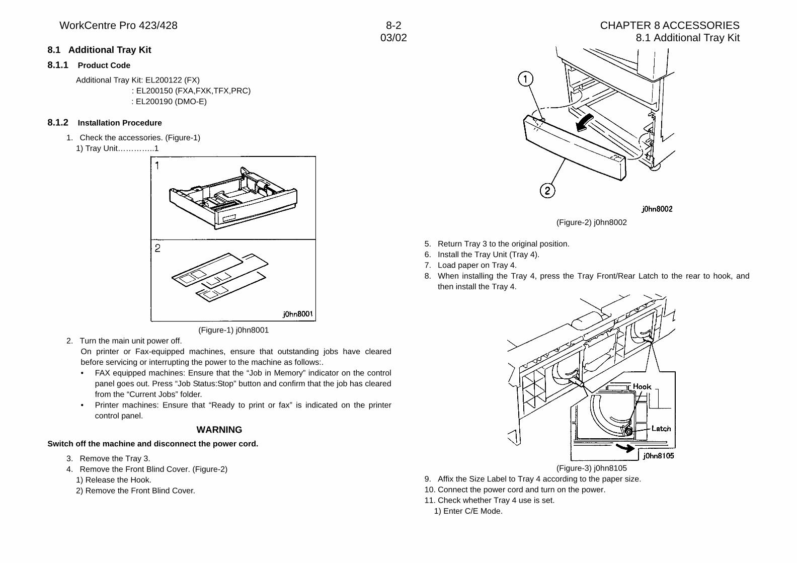
WorkCentre Pro 423/428 8-2 CHAPTER 8 ACCESSORIES03/02 8.1 Additional Tray Kit
8.1 Additional Tray Kit
8.1.1 Product Code
Additional Tray Kit: EL200122 (FX): EL200150 (FXA,FXK,TFX,PRC): EL200190 (DMO-E)
8.1.2 Installation Procedure
1. Check the accessories. (Figure-1)1) Tray Unit…………..1
(Figure-1) j0hn80012. Turn the main unit power off.
On printer or Fax-equipped machines, ensure that outstanding jobs have clearedbefore servicing or interrupting the power to the machine as follows:.• FAX equipped machines: Ensure that the “Job in Memory” indicator on the control
panel goes out. Press “Job Status:Stop” button and confirm that the job has clearedfrom the “Current Jobs” folder.
• Printer machines: Ensure that “Ready to print or fax” is indicated on the printercontrol panel.
WARNINGSwitch off the machine and disconnect the power cord.
3. Remove the Tray 3.4. Remove the Front Blind Cover. (Figure-2)
1) Release the Hook.2) Remove the Front Blind Cover.
(Figure-2) j0hn8002
5. Return Tray 3 to the original position.6. Install the Tray Unit (Tray 4).7. Load paper on Tray 4.8. When installing the Tray 4, press the Tray Front/Rear Latch to the rear to hook, and
then install the Tray 4.
(Figure-3) j0hn81059. Affix the Size Label to Tray 4 according to the paper size.10. Connect the power cord and turn on the power.11. Check whether Tray 4 use is set.
1) Enter C/E Mode.
03/02 8.1 Additional Tray KitWorkCentre Pro 423/428 8-3 CHAPTER 8 ACCESSORIES
2) Set the Chain/Function code "50/62" and press the Start button.3) Change the set value to 1.4) Press the “Restart”.
12. Check the number of Trays.1) Enter C/E Mode.2) Set the Chain/Function code “50/33” and press the Start button.3) Check that the set value is 3.4) Press the “Restart”.
13. Ensure that Tray 4 is displayed on the display of IIT.14. Check that the machine operates normally.15. Store the Front Blind Cover removed in Step 4.
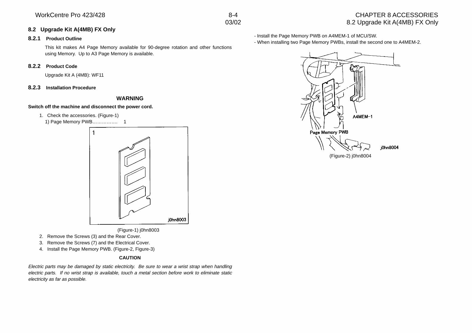
WorkCentre Pro 423/428 8-4 CHAPTER 8 ACCESSORIES03/02 8.2 Upgrade Kit A(4MB) FX Only
8.2 Upgrade Kit A(4MB) FX Only
8.2.1 Product Outline
This kit makes A4 Page Memory available for 90-degree rotation and other functionsusing Memory. Up to A3 Page Memory is available.
8.2.2 Product Code
Upgrade Kit A (4MB): WF11
8.2.3 Installation Procedure
WARNINGSwitch off the machine and disconnect the power cord.
1. Check the accessories. (Figure-1)1) Page Memory PWB……………. 1
(Figure-1) j0hn80032. Remove the Screws (3) and the Rear Cover.3. Remove the Screws (7) and the Electrical Cover.4. Install the Page Memory PWB. (Figure-2, Figure-3)
CAUTION
Electric parts may be damaged by static electricity. Be sure to wear a wrist strap when handlingelectric parts. If no wrist strap is available, touch a metal section before work to eliminate staticelectricity as far as possible.
- Install the Page Memory PWB on A4MEM-1 of MCU/SW.- When installing two Page Memory PWBs, install the second one to A4MEM-2.
(Figure-2) j0hn8004
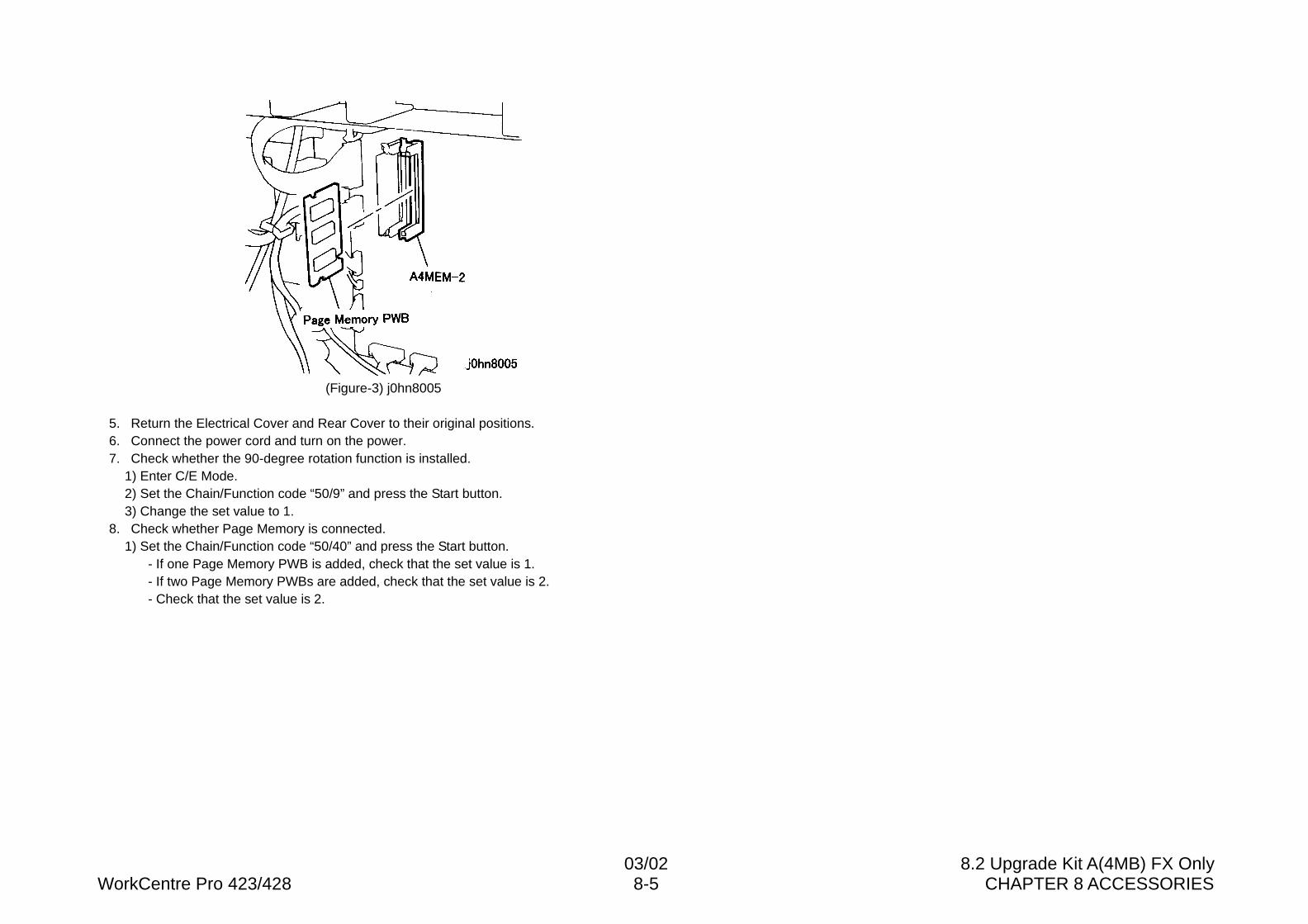
03/02 8.2 Upgrade Kit A(4MB) FX OnlyWorkCentre Pro 423/428 8-5 CHAPTER 8 ACCESSORIES
(Figure-3) j0hn8005
5. Return the Electrical Cover and Rear Cover to their original positions.6. Connect the power cord and turn on the power.7. Check whether the 90-degree rotation function is installed.
1) Enter C/E Mode.2) Set the Chain/Function code “50/9” and press the Start button.3) Change the set value to 1.
8. Check whether Page Memory is connected.1) Set the Chain/Function code “50/40” and press the Start button.
- If one Page Memory PWB is added, check that the set value is 1.- If two Page Memory PWBs are added, check that the set value is 2.- Check that the set value is 2.
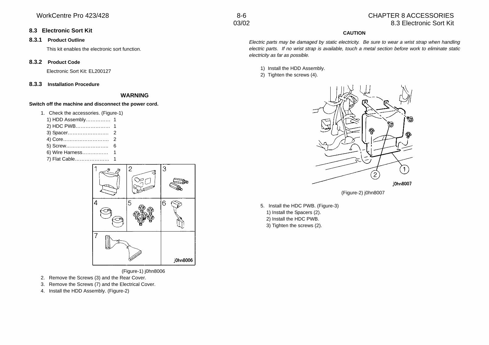
WorkCentre Pro 423/428 8-6 CHAPTER 8 ACCESSORIES03/02 8.3 Electronic Sort Kit
8.3 Electronic Sort Kit
8.3.1 Product Outline
This kit enables the electronic sort function.
8.3.2 Product Code
Electronic Sort Kit: EL200127
8.3.3 Installation Procedure
WARNINGSwitch off the machine and disconnect the power cord.
1. Check the accessories. (Figure-1)1) HDD Assembly…………… 12) HDC PWB………………… 13) Spacer……………………. 24) Core………………………. 25) Screw…………………….. 66) Wire Harness……….…… 17) Flat Cable………………… 1
(Figure-1) j0hn80062. Remove the Screws (3) and the Rear Cover.3. Remove the Screws (7) and the Electrical Cover.4. Install the HDD Assembly. (Figure-2)
CAUTION
Electric parts may be damaged by static electricity. Be sure to wear a wrist strap when handlingelectric parts. If no wrist strap is available, touch a metal section before work to eliminate staticelectricity as far as possible.
1) Install the HDD Assembly.2) Tighten the screws (4).
(Figure-2) j0hn8007
5. Install the HDC PWB. (Figure-3)1) Install the Spacers (2).2) Install the HDC PWB.3) Tighten the screws (2).
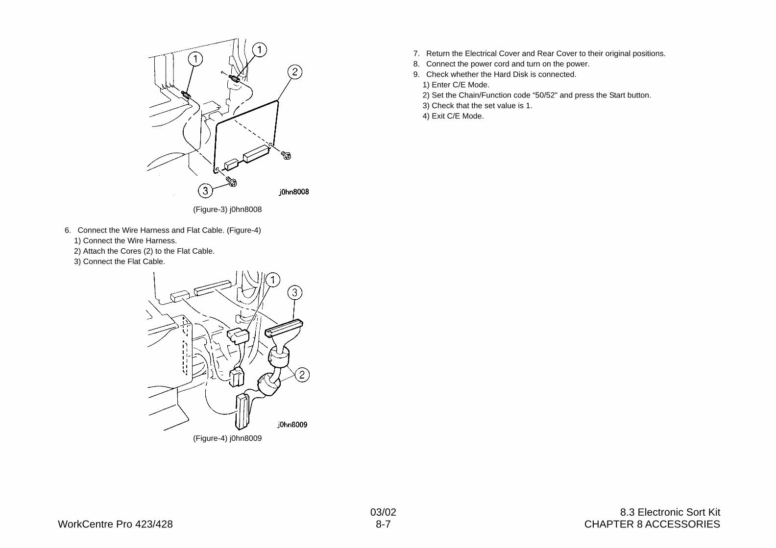
03/02 8.3 Electronic Sort KitWorkCentre Pro 423/428 8-7 CHAPTER 8 ACCESSORIES
(Figure-3) j0hn8008
6. Connect the Wire Harness and Flat Cable. (Figure-4)1) Connect the Wire Harness.2) Attach the Cores (2) to the Flat Cable.3) Connect the Flat Cable.
(Figure-4) j0hn8009
7. Return the Electrical Cover and Rear Cover to their original positions.8. Connect the power cord and turn on the power.9. Check whether the Hard Disk is connected.
1) Enter C/E Mode.2) Set the Chain/Function code “50/52" and press the Start button.3) Check that the set value is 1.4) Exit C/E Mode.
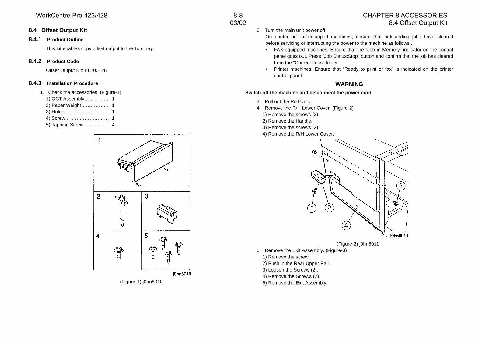
WorkCentre Pro 423/428 8-8 CHAPTER 8 ACCESSORIES03/02 8.4 Offset Output Kit
8.4 Offset Output Kit
8.4.1 Product Outline
This kit enables copy offset output to the Top Tray.
8.4.2 Product Code
Offset Output Kit: EL200126
8.4.3 Installation Procedure
1. Check the accessories. (Figure-1)1) OCT Assembly…………… 12) Paper Weight…………….. 13) Holder……………………... 14) Screw……………………… 15) Tapping Screw…………… 4
(Figure-1) j0hn8010
2. Turn the main unit power off.On printer or Fax-equipped machines, ensure that outstanding jobs have clearedbefore servicing or interrupting the power to the machine as follows:.• FAX equipped machines: Ensure that the “Job in Memory” indicator on the control
panel goes out. Press “Job Status:Stop” button and confirm that the job has clearedfrom the “Current Jobs” folder.
• Printer machines: Ensure that “Ready to print or fax” is indicated on the printercontrol panel.
WARNINGSwitch off the machine and disconnect the power cord.
3. Pull out the R/H Unit.4. Remove the R/H Lower Cover. (Figure-2)
1) Remove the screws (2).2) Remove the Handle.3) Remove the screws (2).4) Remove the R/H Lower Cover.
(Figure-2) j0hn80115. Remove the Exit Assembly. (Figure-3)
1) Remove the screw.2) Push in the Rear Upper Rail.3) Loosen the Screws (2).4) Remove the Screws (2).5) Remove the Exit Assembly.
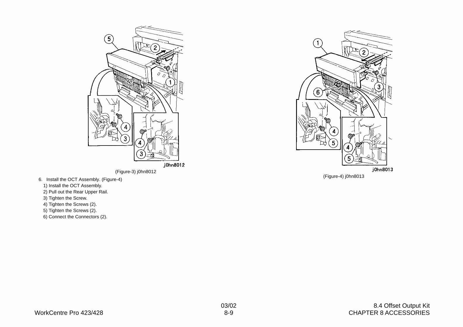
03/02 8.4 Offset Output KitWorkCentre Pro 423/428 8-9 CHAPTER 8 ACCESSORIES
(Figure-3) j0hn8012
6. Install the OCT Assembly. (Figure-4)1) Install the OCT Assembly.2) Pull out the Rear Upper Rail.3) Tighten the Screw.4) Tighten the Screws (2).5) Tighten the Screws (2).6) Connect the Connectors (2).
(Figure-4) j0hn8013
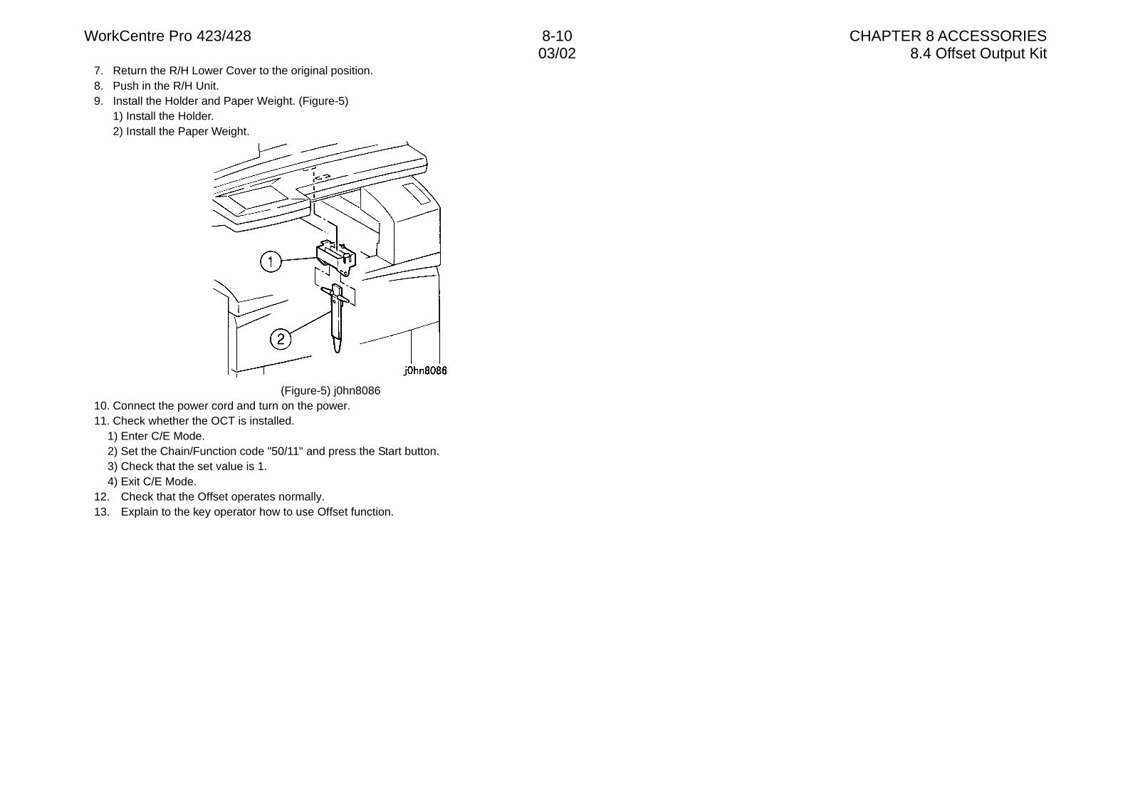
WorkCentre Pro 423/428 8-10 CHAPTER 8 ACCESSORIES03/02 8.4 Offset Output Kit
7. Return the R/H Lower Cover to the original position.8. Push in the R/H Unit.9. Install the Holder and Paper Weight. (Figure-5)
1) Install the Holder.2) Install the Paper Weight.
(Figure-5) j0hn808610. Connect the power cord and turn on the power.11. Check whether the OCT is installed.
1) Enter C/E Mode.2) Set the Chain/Function code "50/11" and press the Start button.3) Check that the set value is 1.4) Exit C/E Mode.
12. Check that the Offset operates normally.13. Explain to the key operator how to use Offset function.
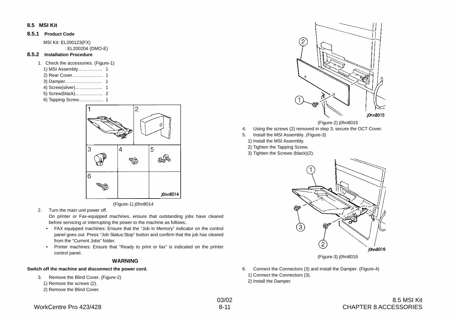
03/02 8.5 MSI KitWorkCentre Pro 423/428 8-11 CHAPTER 8 ACCESSORIES
8.5 MSI Kit
8.5.1 Product Code
MSI Kit: EL200123(FX) : EL200204 (DMO-E)
8.5.2 Installation Procedure
1. Check the accessories. (Figure-1)1) MSI Assembly……….…… 12) Rear Cover……….………. 13) Damper…………………… 14) Screw(silver)……………... 15) Screw(black)……………… 26) Tapping Screw……………. 1
(Figure-1) j0hn80142. Turn the main unit power off.
On printer or Fax-equipped machines, ensure that outstanding jobs have clearedbefore servicing or interrupting the power to the machine as follows:.
• FAX equipped machines: Ensure that the “Job in Memory” indicator on the controlpanel goes out. Press “Job Status:Stop” button and confirm that the job has clearedfrom the “Current Jobs” folder.
• Printer machines: Ensure that “Ready to print or fax” is indicated on the printercontrol panel.
WARNINGSwitch off the machine and disconnect the power cord.
3. Remove the Blind Cover. (Figure-2)1) Remove the screws (2).2) Remove the Blind Cover.
(Figure-2) j0hn80154. Using the screws (2) removed in step 3, secure the OCT Cover.5. Install the MSI Assembly. (Figure-3)
1) Install the MSI Assembly.2) Tighten the Tapping Screw.3) Tighten the Screws (black)(2).
(Figure-3) j0hn8016
6. Connect the Connectors (3) and install the Damper. (Figure-4)1) Connect the Connectors (3).2) Install the Damper.
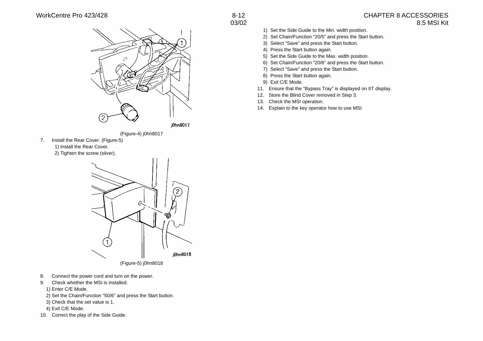
WorkCentre Pro 423/428 8-12 CHAPTER 8 ACCESSORIES03/02 8.5 MSI Kit
(Figure-4) j0hn80177. Install the Rear Cover. (Figure-5)
1) Install the Rear Cover.2) Tighten the screw (silver).
(Figure-5) j0hn8018
8. Connect the power cord and turn on the power.9. Check whether the MSI is installed.
1) Enter C/E Mode.2) Set the Chain/Function "50/6" and press the Start button.3) Check that the set value is 1.4) Exit C/E Mode.
10. Correct the play of the Side Guide.
1) Set the Side Guide to the Min. width position.2) Set Chain/Function “20/5” and press the Start button.3) Select “Save” and press the Start button.4) Press the Start button again.5) Set the Side Guide to the Max. width position.6) Set Chain/Function “20/6” and press the Start button.7) Select “Save” and press the Start button.8) Press the Start button again.9) Exit C/E Mode.
11. Ensure that the “Bypass Tray” is displayed on IIT display.12. Store the Blind Cover removed in Step 3.13. Check the MSI operation.14. Explain to the key operator how to use MSI.
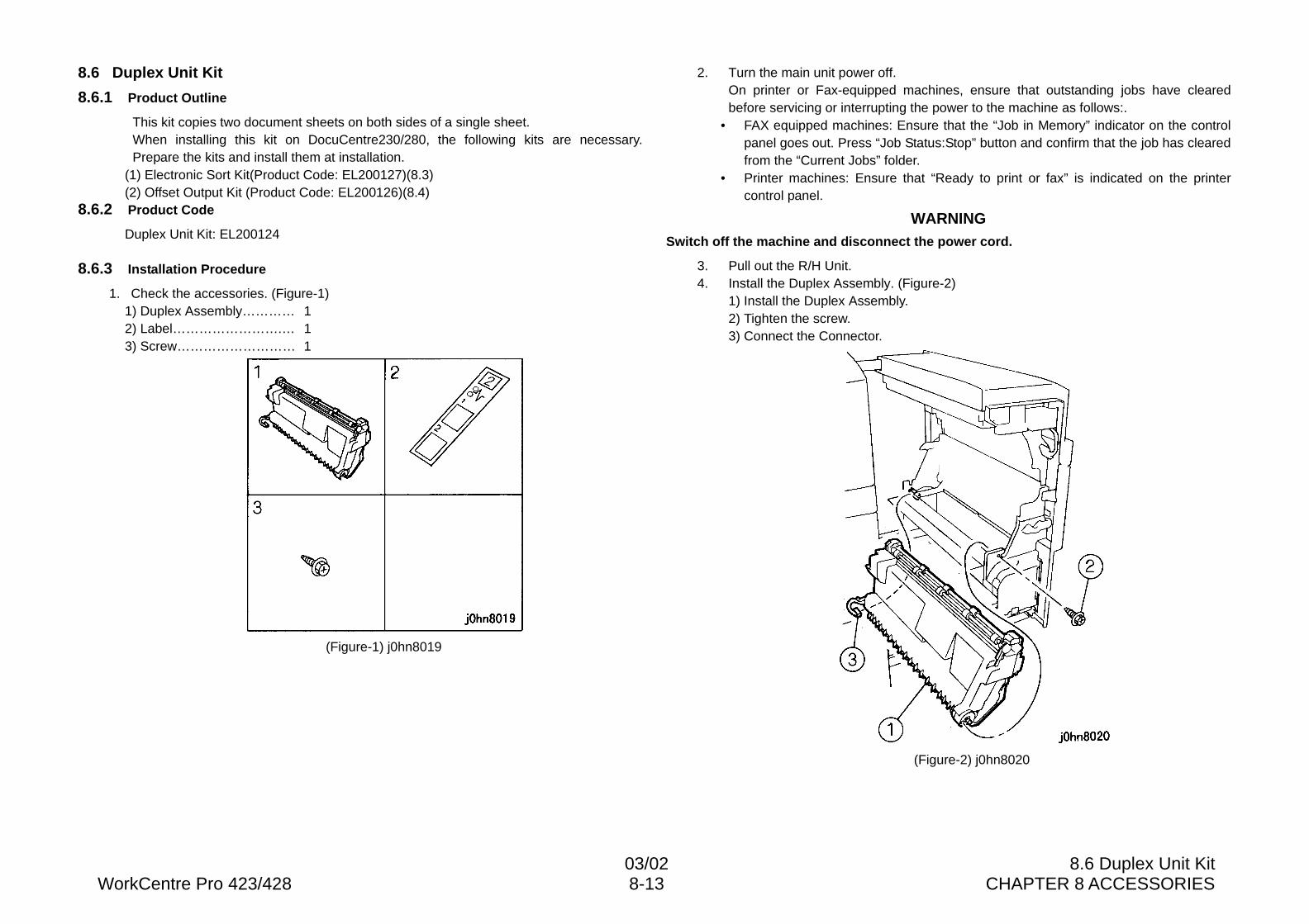
03/02 8.6 Duplex Unit KitWorkCentre Pro 423/428 8-13 CHAPTER 8 ACCESSORIES
8.6 Duplex Unit Kit
8.6.1 Product Outline
This kit copies two document sheets on both sides of a single sheet.When installing this kit on DocuCentre230/280, the following kits are necessary.Prepare the kits and install them at installation.
(1) Electronic Sort Kit(Product Code: EL200127)(8.3)(2) Offset Output Kit (Product Code: EL200126)(8.4)
8.6.2 Product Code
Duplex Unit Kit: EL200124
8.6.3 Installation Procedure
1. Check the accessories. (Figure-1)1) Duplex Assembly………… 12) Label…………………….… 13) Screw……………………… 1
(Figure-1) j0hn8019
2. Turn the main unit power off.On printer or Fax-equipped machines, ensure that outstanding jobs have clearedbefore servicing or interrupting the power to the machine as follows:.
• FAX equipped machines: Ensure that the “Job in Memory” indicator on the controlpanel goes out. Press “Job Status:Stop” button and confirm that the job has clearedfrom the “Current Jobs” folder.
• Printer machines: Ensure that “Ready to print or fax” is indicated on the printercontrol panel.
WARNINGSwitch off the machine and disconnect the power cord.
3. Pull out the R/H Unit.4. Install the Duplex Assembly. (Figure-2)
1) Install the Duplex Assembly.2) Tighten the screw.3) Connect the Connector.
(Figure-2) j0hn8020
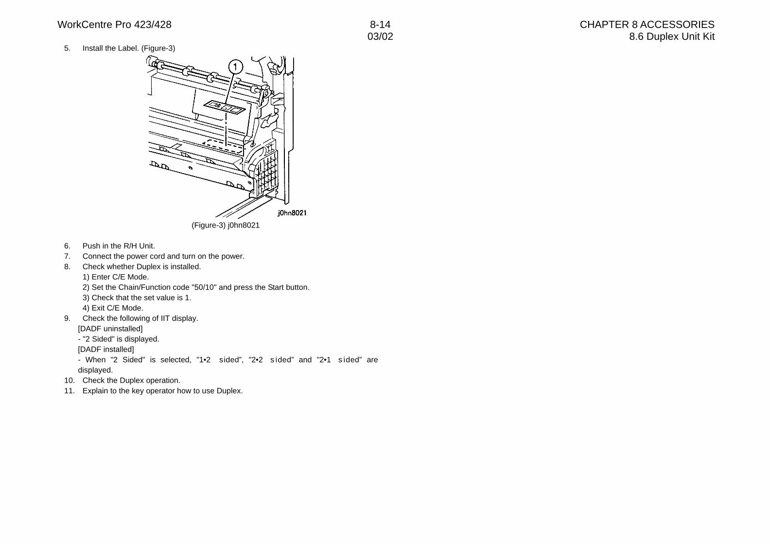
WorkCentre Pro 423/428 8-14 CHAPTER 8 ACCESSORIES03/02 8.6 Duplex Unit Kit
5. Install the Label. (Figure-3)
(Figure-3) j0hn8021
6. Push in the R/H Unit.7. Connect the power cord and turn on the power.8. Check whether Duplex is installed.
1) Enter C/E Mode.2) Set the Chain/Function code "50/10" and press the Start button.3) Check that the set value is 1.4) Exit C/E Mode.
9. Check the following of IIT display.[DADF uninstalled]- "2 Sided" is displayed.[DADF installed]- When "2 Sided" is selected, "1•2 sided”, "2•2 s ided” and "2•1 s ided” aredisplayed.
10. Check the Duplex operation.11. Explain to the key operator how to use Duplex.
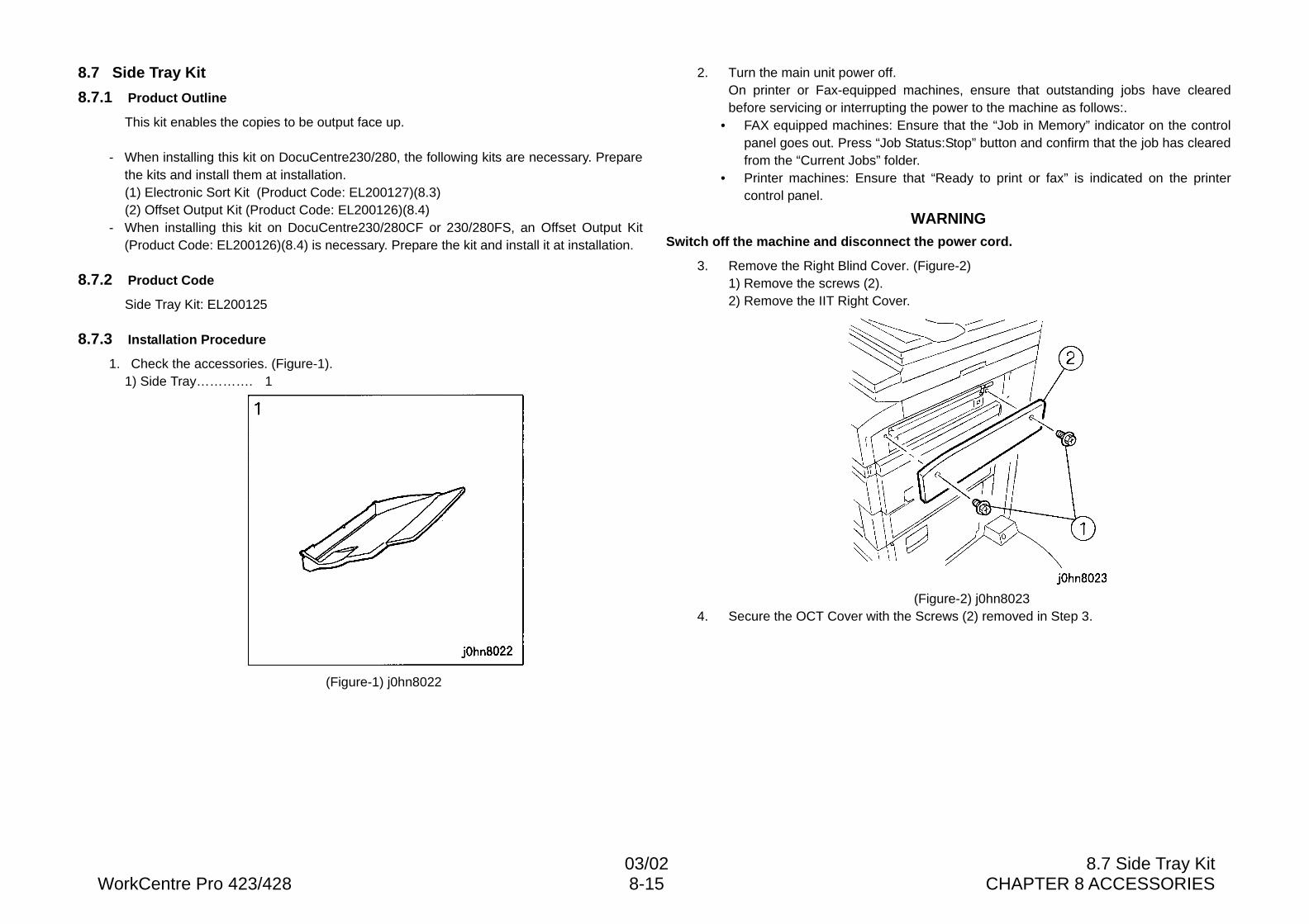
03/02 8.7 Side Tray KitWorkCentre Pro 423/428 8-15 CHAPTER 8 ACCESSORIES
8.7 Side Tray Kit
8.7.1 Product Outline
This kit enables the copies to be output face up.
- When installing this kit on DocuCentre230/280, the following kits are necessary. Preparethe kits and install them at installation.(1) Electronic Sort Kit (Product Code: EL200127)(8.3)(2) Offset Output Kit (Product Code: EL200126)(8.4)
- When installing this kit on DocuCentre230/280CF or 230/280FS, an Offset Output Kit(Product Code: EL200126)(8.4) is necessary. Prepare the kit and install it at installation.
8.7.2 Product Code
Side Tray Kit: EL200125
8.7.3 Installation Procedure
1. Check the accessories. (Figure-1).1) Side Tray…………. 1
(Figure-1) j0hn8022
2. Turn the main unit power off.On printer or Fax-equipped machines, ensure that outstanding jobs have clearedbefore servicing or interrupting the power to the machine as follows:.
• FAX equipped machines: Ensure that the “Job in Memory” indicator on the controlpanel goes out. Press “Job Status:Stop” button and confirm that the job has clearedfrom the “Current Jobs” folder.
• Printer machines: Ensure that “Ready to print or fax” is indicated on the printercontrol panel.
WARNINGSwitch off the machine and disconnect the power cord.
3. Remove the Right Blind Cover. (Figure-2)1) Remove the screws (2).2) Remove the IIT Right Cover.
(Figure-2) j0hn80234. Secure the OCT Cover with the Screws (2) removed in Step 3.
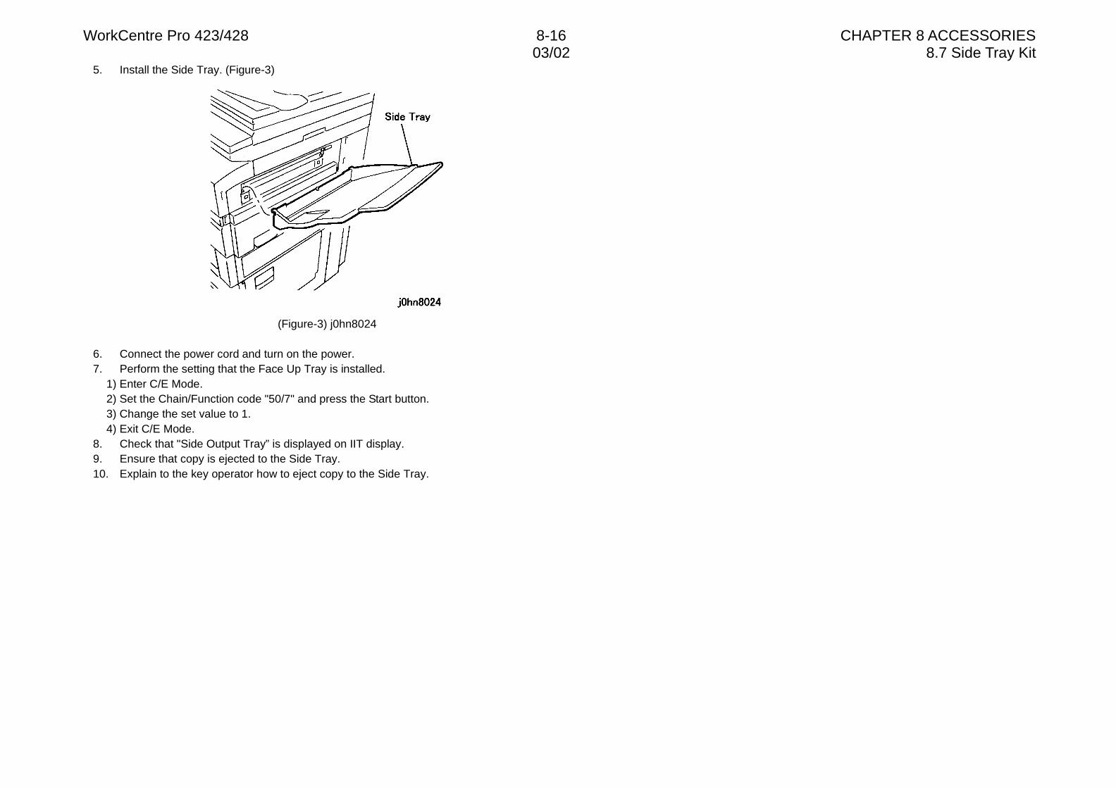
WorkCentre Pro 423/428 8-16 CHAPTER 8 ACCESSORIES03/02 8.7 Side Tray Kit
5. Install the Side Tray. (Figure-3)
(Figure-3) j0hn8024
6. Connect the power cord and turn on the power.7. Perform the setting that the Face Up Tray is installed.
1) Enter C/E Mode.2) Set the Chain/Function code "50/7" and press the Start button.3) Change the set value to 1.4) Exit C/E Mode.
8. Check that "Side Output Tray” is displayed on IIT display.9. Ensure that copy is ejected to the Side Tray.10. Explain to the key operator how to eject copy to the Side Tray.
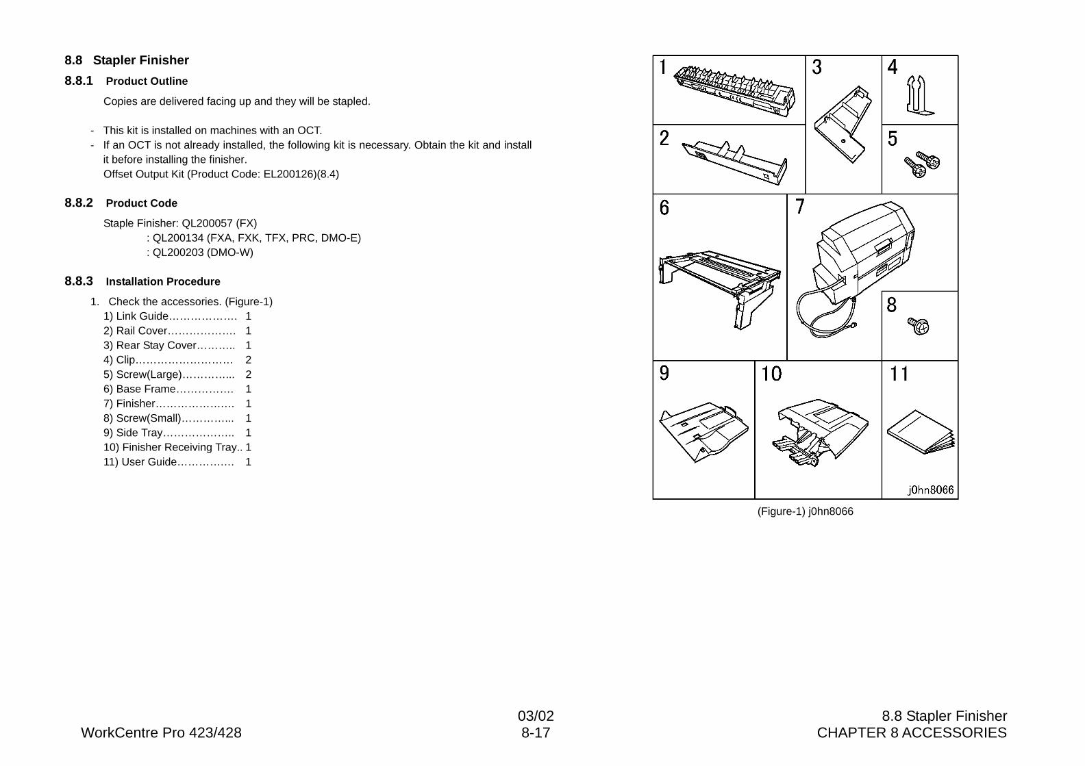
03/02 8.8 Stapler FinisherWorkCentre Pro 423/428 8-17 CHAPTER 8 ACCESSORIES
8.8 Stapler Finisher
8.8.1 Product Outline
Copies are delivered facing up and they will be stapled.
- This kit is installed on machines with an OCT.- If an OCT is not already installed, the following kit is necessary. Obtain the kit and install
it before installing the finisher.Offset Output Kit (Product Code: EL200126)(8.4)
8.8.2 Product Code
Staple Finisher: QL200057 (FX): QL200134 (FXA, FXK, TFX, PRC, DMO-E): QL200203 (DMO-W)
8.8.3 Installation Procedure
1. Check the accessories. (Figure-1)1) Link Guide………………. 12) Rail Cover………………. 13) Rear Stay Cover……….. 14) Clip……………………… 25) Screw(Large)…………... 26) Base Frame……………. 17) Finisher……………….… 18) Screw(Small)…………... 19) Side Tray……………….. 110) Finisher Receiving Tray.. 111) User Guide………….… 1
(Figure-1) j0hn8066
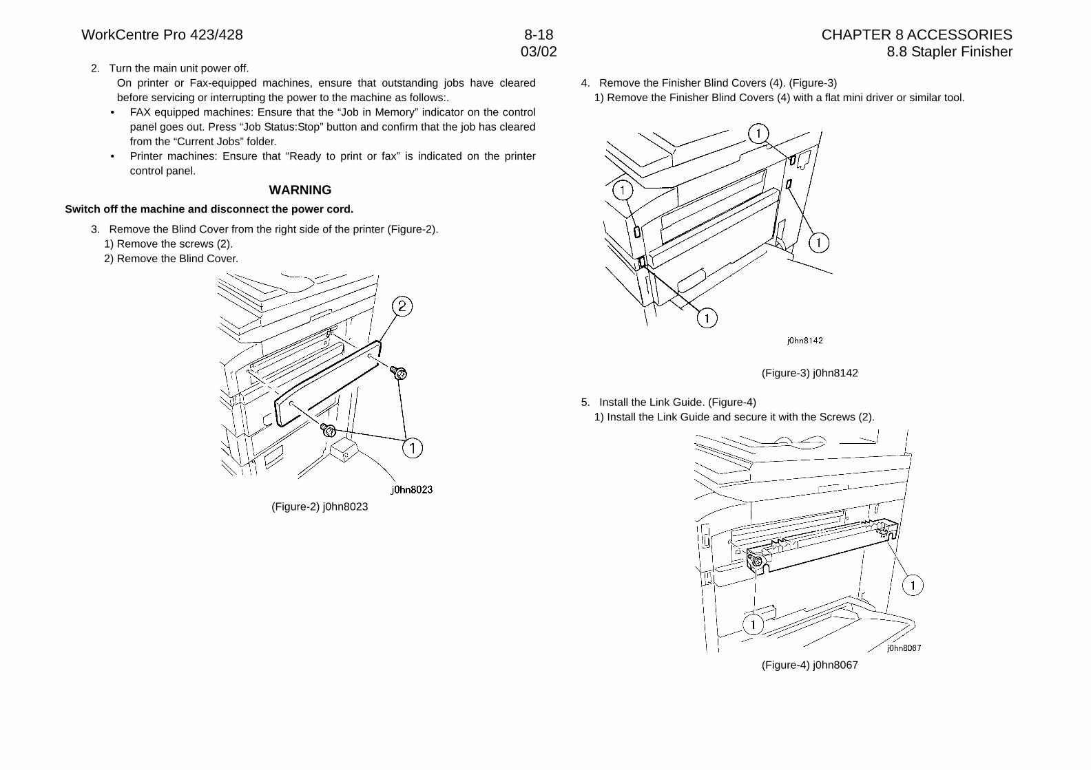
WorkCentre Pro 423/428 8-18 CHAPTER 8 ACCESSORIES03/02 8.8 Stapler Finisher
2. Turn the main unit power off.On printer or Fax-equipped machines, ensure that outstanding jobs have clearedbefore servicing or interrupting the power to the machine as follows:.
• FAX equipped machines: Ensure that the “Job in Memory” indicator on the controlpanel goes out. Press “Job Status:Stop” button and confirm that the job has clearedfrom the “Current Jobs” folder.
• Printer machines: Ensure that “Ready to print or fax” is indicated on the printercontrol panel.
WARNINGSwitch off the machine and disconnect the power cord.
3. Remove the Blind Cover from the right side of the printer (Figure-2).1) Remove the screws (2).2) Remove the Blind Cover.
(Figure-2) j0hn8023
4. Remove the Finisher Blind Covers (4). (Figure-3)1) Remove the Finisher Blind Covers (4) with a flat mini driver or similar tool.
(Figure-3) j0hn8142
5. Install the Link Guide. (Figure-4)1) Install the Link Guide and secure it with the Screws (2).
(Figure-4) j0hn8067
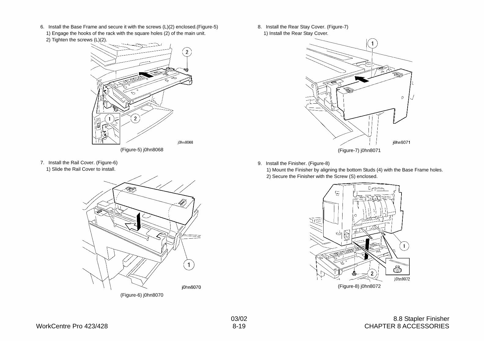
03/02 8.8 Stapler FinisherWorkCentre Pro 423/428 8-19 CHAPTER 8 ACCESSORIES
6. Install the Base Frame and secure it with the screws (L)(2) enclosed.(Figure-5)1) Engage the hooks of the rack with the square holes (2) of the main unit.2) Tighten the screws (L)(2).
(Figure-5) j0hn8068
7. Install the Rail Cover. (Figure-6)1) Slide the Rail Cover to install.
(Figure-6) j0hn8070
8. Install the Rear Stay Cover. (Figure-7)1) Install the Rear Stay Cover.
(Figure-7) j0hn8071
9. Install the Finisher. (Figure-8)1) Mount the Finisher by aligning the bottom Studs (4) with the Base Frame holes.2) Secure the Finisher with the Screw (S) enclosed.
(Figure-8) j0hn8072
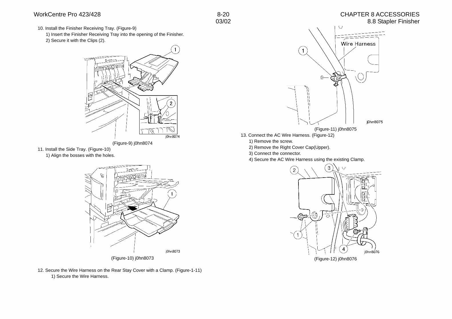
WorkCentre Pro 423/428 8-20 CHAPTER 8 ACCESSORIES03/02 8.8 Stapler Finisher
10. Install the Finisher Receiving Tray. (Figure-9)1) Insert the Finisher Receiving Tray into the opening of the Finisher.2) Secure it with the Clips (2).
(Figure-9) j0hn807411. Install the Side Tray. (Figure-10)
1) Align the bosses with the holes.
(Figure-10) j0hn8073
12. Secure the Wire Harness on the Rear Stay Cover with a Clamp. (Figure-1-11)1) Secure the Wire Harness.
(Figure-11) j0hn807513. Connect the AC Wire Harness. (Figure-12)
1) Remove the screw.2) Remove the Right Cover Cap(Upper).3) Connect the connector.4) Secure the AC Wire Harness using the existing Clamp.
(Figure-12) j0hn8076
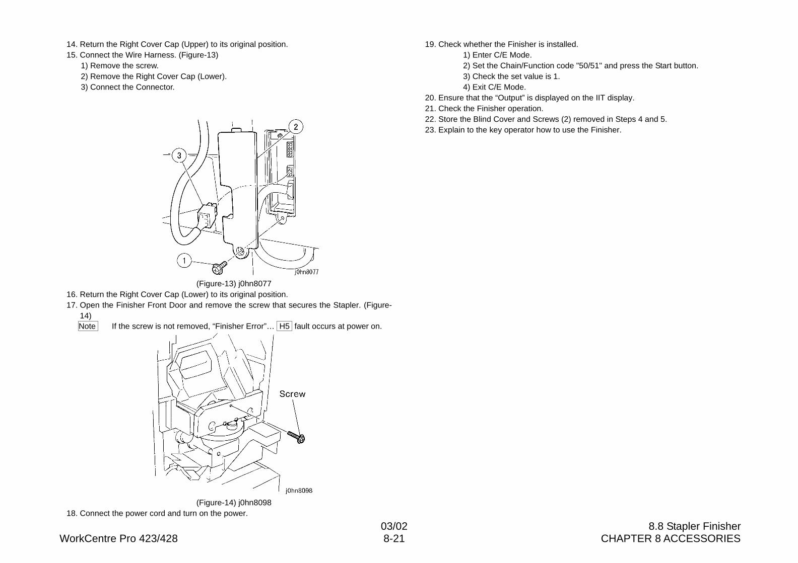
03/02 8.8 Stapler FinisherWorkCentre Pro 423/428 8-21 CHAPTER 8 ACCESSORIES
14. Return the Right Cover Cap (Upper) to its original position.15. Connect the Wire Harness. (Figure-13)
1) Remove the screw.2) Remove the Right Cover Cap (Lower).3) Connect the Connector.
(Figure-13) j0hn807716. Return the Right Cover Cap (Lower) to its original position.17. Open the Finisher Front Door and remove the screw that secures the Stapler. (Figure-
14)Note If the screw is not removed, “Finisher Error”… H5 fault occurs at power on.
(Figure-14) j0hn809818. Connect the power cord and turn on the power.
19. Check whether the Finisher is installed.1) Enter C/E Mode.2) Set the Chain/Function code "50/51" and press the Start button.3) Check the set value is 1.4) Exit C/E Mode.
20. Ensure that the “Output” is displayed on the IIT display.21. Check the Finisher operation.22. Store the Blind Cover and Screws (2) removed in Steps 4 and 5.23. Explain to the key operator how to use the Finisher.
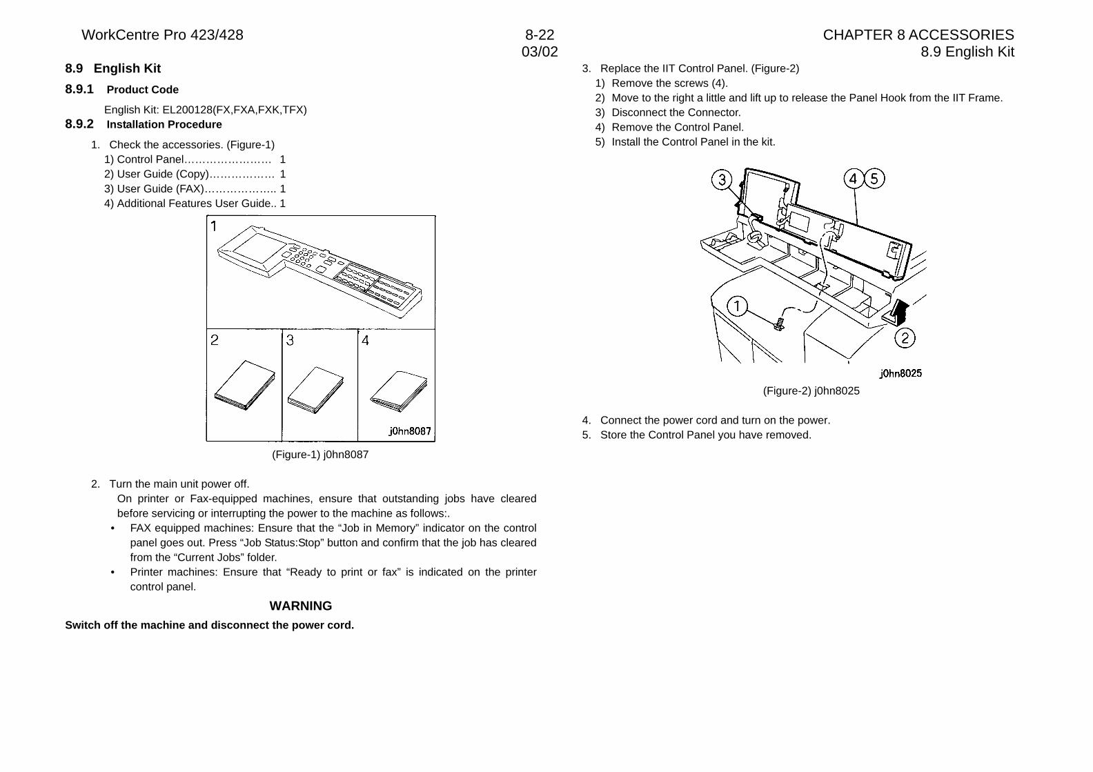
WorkCentre Pro 423/428 8-22 CHAPTER 8 ACCESSORIES03/02 8.9 English Kit
8.9 English Kit
8.9.1 Product Code
English Kit: EL200128(FX,FXA,FXK,TFX)8.9.2 Installation Procedure
1. Check the accessories. (Figure-1)1) Control Panel…………………… 12) User Guide (Copy)……………… 13) User Guide (FAX)……………….. 14) Additional Features User Guide.. 1
(Figure-1) j0hn8087
2. Turn the main unit power off.On printer or Fax-equipped machines, ensure that outstanding jobs have clearedbefore servicing or interrupting the power to the machine as follows:.
• FAX equipped machines: Ensure that the “Job in Memory” indicator on the controlpanel goes out. Press “Job Status:Stop” button and confirm that the job has clearedfrom the “Current Jobs” folder.
• Printer machines: Ensure that “Ready to print or fax” is indicated on the printercontrol panel.
WARNINGSwitch off the machine and disconnect the power cord.
3. Replace the IIT Control Panel. (Figure-2)1) Remove the screws (4).2) Move to the right a little and lift up to release the Panel Hook from the IIT Frame.3) Disconnect the Connector.4) Remove the Control Panel.5) Install the Control Panel in the kit.
(Figure-2) j0hn8025
4. Connect the power cord and turn on the power.5. Store the Control Panel you have removed.
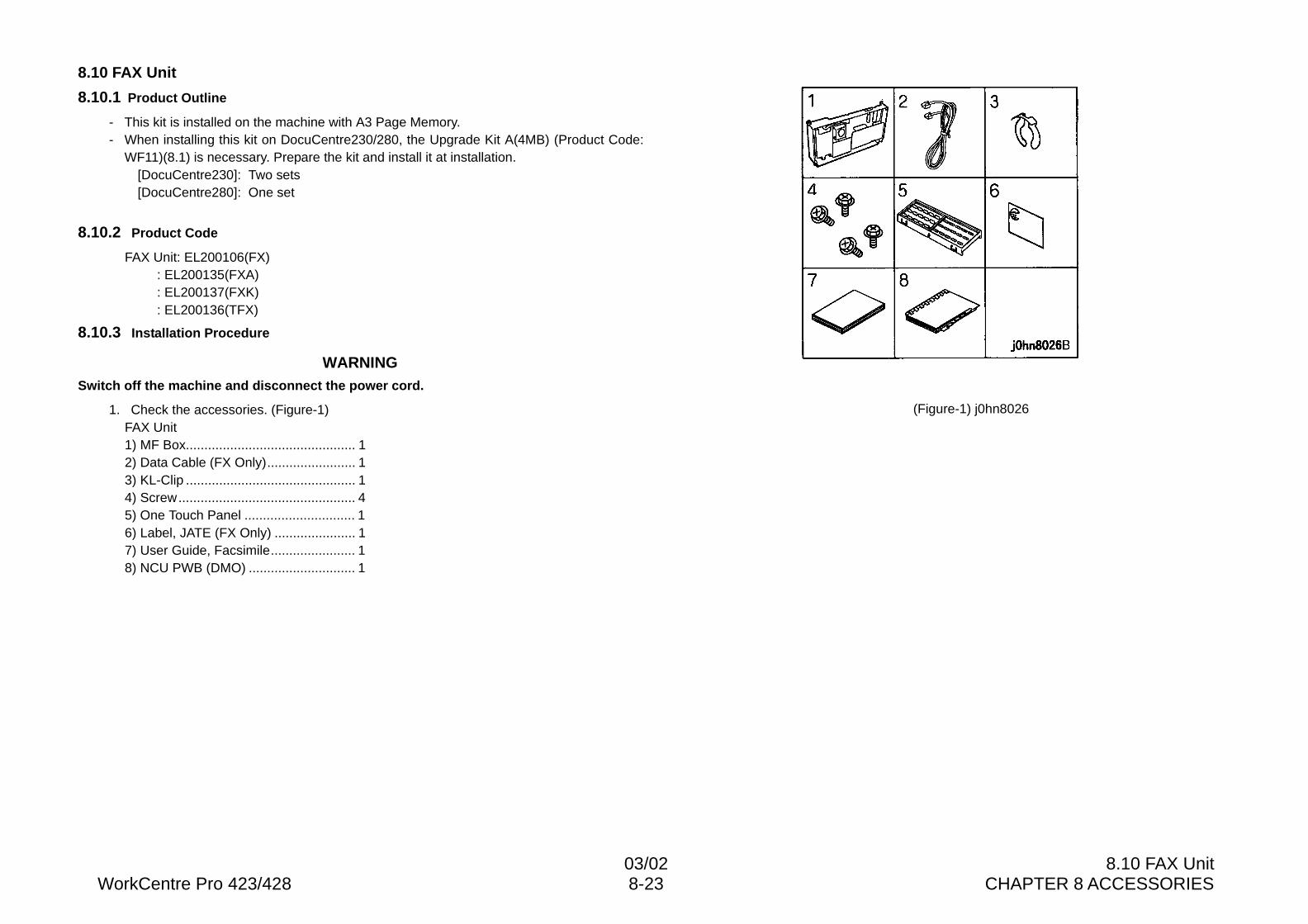
03/02 8.10 FAX UnitWorkCentre Pro 423/428 8-23 CHAPTER 8 ACCESSORIES
8.10 FAX Unit
8.10.1 Product Outline
- This kit is installed on the machine with A3 Page Memory.- When installing this kit on DocuCentre230/280, the Upgrade Kit A(4MB) (Product Code:
WF11)(8.1) is necessary. Prepare the kit and install it at installation.[DocuCentre230]: Two sets[DocuCentre280]: One set
8.10.2 Product Code
FAX Unit: EL200106(FX): EL200135(FXA): EL200137(FXK): EL200136(TFX)
8.10.3 Installation Procedure
WARNINGSwitch off the machine and disconnect the power cord.
1. Check the accessories. (Figure-1)FAX Unit1) MF Box.............................................. 12) Data Cable (FX Only)........................ 13) KL-Clip .............................................. 14) Screw................................................ 45) One Touch Panel .............................. 16) Label, JATE (FX Only) ...................... 17) User Guide, Facsimile....................... 18) NCU PWB (DMO) ............................. 1
(Figure-1) j0hn8026
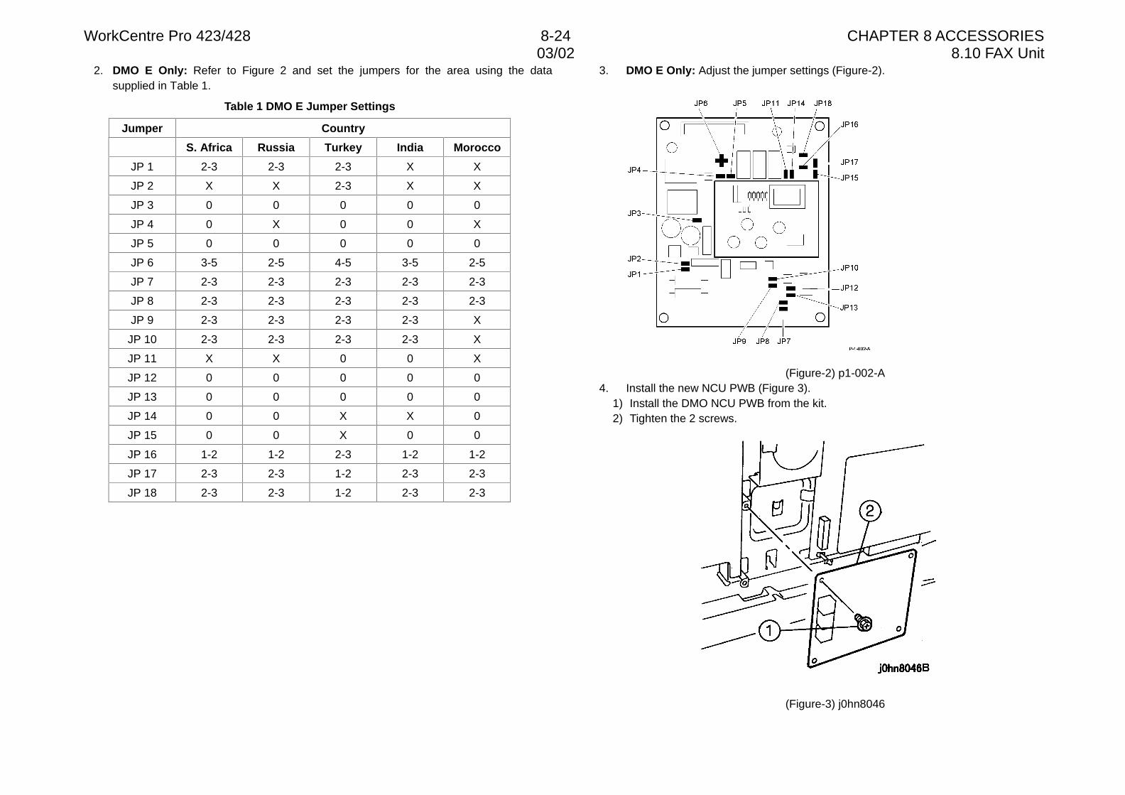
WorkCentre Pro 423/428 8-24 CHAPTER 8 ACCESSORIES03/02 8.10 FAX Unit
2. DMO E Only: Refer to Figure 2 and set the jumpers for the area using the datasupplied in Table 1.
Table 1 DMO E Jumper Settings
Jumper Country
S. Africa Russia Turkey India Morocco
JP 1 2-3 2-3 2-3 X X
JP 2 X X 2-3 X X
JP 3 0 0 0 0 0
JP 4 0 X 0 0 X
JP 5 0 0 0 0 0
JP 6 3-5 2-5 4-5 3-5 2-5
JP 7 2-3 2-3 2-3 2-3 2-3
JP 8 2-3 2-3 2-3 2-3 2-3
JP 9 2-3 2-3 2-3 2-3 X
JP 10 2-3 2-3 2-3 2-3 X
JP 11 X X 0 0 X
JP 12 0 0 0 0 0
JP 13 0 0 0 0 0
JP 14 0 0 X X 0
JP 15 0 0 X 0 0
JP 16 1-2 1-2 2-3 1-2 1-2
JP 17 2-3 2-3 1-2 2-3 2-3
JP 18 2-3 2-3 1-2 2-3 2-3
3. DMO E Only: Adjust the jumper settings (Figure-2).
(Figure-2) p1-002-A4. Install the new NCU PWB (Figure 3).
1) Install the DMO NCU PWB from the kit.2) Tighten the 2 screws.
(Figure-3) j0hn8046
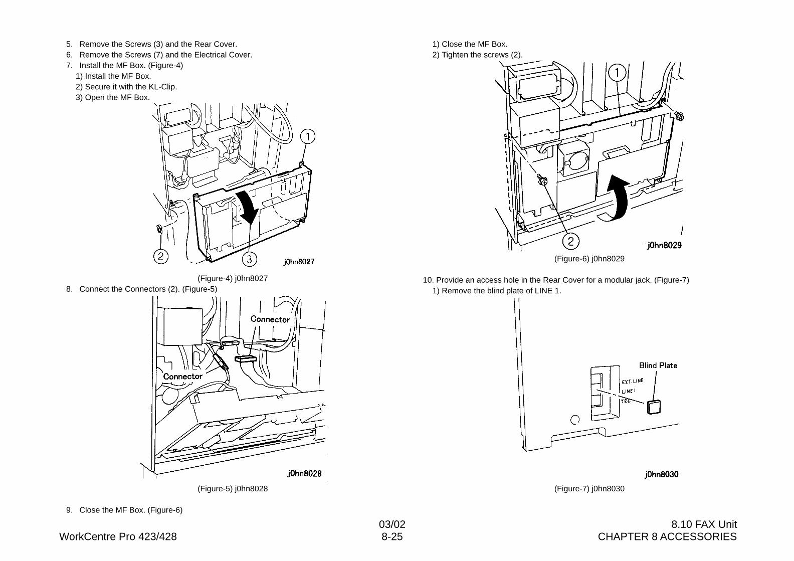
03/02 8.10 FAX UnitWorkCentre Pro 423/428 8-25 CHAPTER 8 ACCESSORIES
5. Remove the Screws (3) and the Rear Cover.6. Remove the Screws (7) and the Electrical Cover.7. Install the MF Box. (Figure-4)
1) Install the MF Box.2) Secure it with the KL-Clip.3) Open the MF Box.
(Figure-4) j0hn80278. Connect the Connectors (2). (Figure-5)
(Figure-5) j0hn8028
9. Close the MF Box. (Figure-6)
1) Close the MF Box.2) Tighten the screws (2).
(Figure-6) j0hn8029
10. Provide an access hole in the Rear Cover for a modular jack. (Figure-7)1) Remove the blind plate of LINE 1.
(Figure-7) j0hn8030
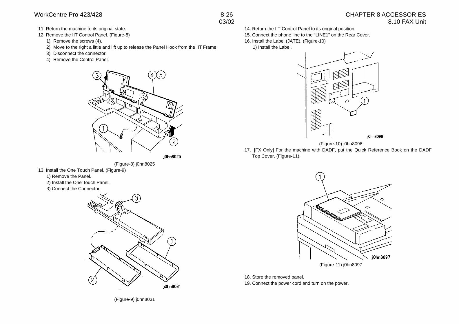
WorkCentre Pro 423/428 8-26 CHAPTER 8 ACCESSORIES03/02 8.10 FAX Unit
11. Return the machine to its original state.12. Remove the IIT Control Panel. (Figure-8)
1) Remove the screws (4).2) Move to the right a little and lift up to release the Panel Hook from the IIT Frame.3) Disconnect the connector.4) Remove the Control Panel.
(Figure-8) j0hn802513. Install the One Touch Panel. (Figure-9)
1) Remove the Panel.2) Install the One Touch Panel.3) Connect the Connector.
(Figure-9) j0hn8031
14. Return the IIT Control Panel to its original position.15. Connect the phone line to the “LINE1” on the Rear Cover.16. Install the Label (JATE). (Figure-10)
1) Install the Label.
(Figure-10) j0hn809617. [FX Only] For the machine with DADF, put the Quick Reference Book on the DADF
Top Cover. (Figure-11).
(Figure-11) j0hn8097
18. Store the removed panel.19. Connect the power cord and turn on the power.
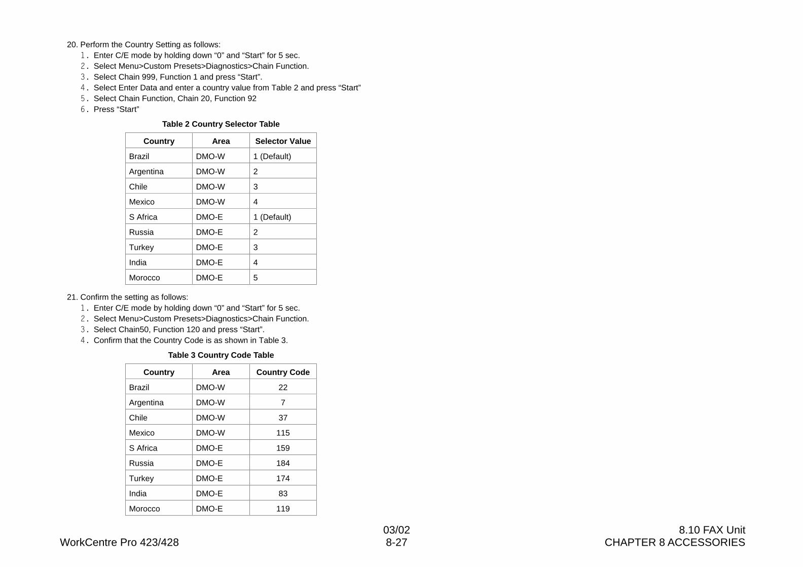
03/02 8.10 FAX UnitWorkCentre Pro 423/428 8-27 CHAPTER 8 ACCESSORIES
20. Perform the Country Setting as follows:�� Enter C/E mode by holding down “0” and “Start” for 5 sec.�� Select Menu>Custom Presets>Diagnostics>Chain Function.�� Select Chain 999, Function 1 and press “Start”.�� Select Enter Data and enter a country value from Table 2 and press “Start”�� Select Chain Function, Chain 20, Function 92�� Press “Start”
Table 2 Country Selector Table
Country Area Selector Value
Brazil DMO-W 1 (Default)
Argentina DMO-W 2
Chile DMO-W 3
Mexico DMO-W 4
S Africa DMO-E 1 (Default)
Russia DMO-E 2
Turkey DMO-E 3
India DMO-E 4
Morocco DMO-E 5
21. Confirm the setting as follows:�� Enter C/E mode by holding down “0” and “Start” for 5 sec.�� Select Menu>Custom Presets>Diagnostics>Chain Function.�� Select Chain50, Function 120 and press “Start”.�� Confirm that the Country Code is as shown in Table 3.
Table 3 Country Code Table
Country Area Country Code
Brazil DMO-W 22
Argentina DMO-W 7
Chile DMO-W 37
Mexico DMO-W 115
S Africa DMO-E 159
Russia DMO-E 184
Turkey DMO-E 174
India DMO-E 83
Morocco DMO-E 119
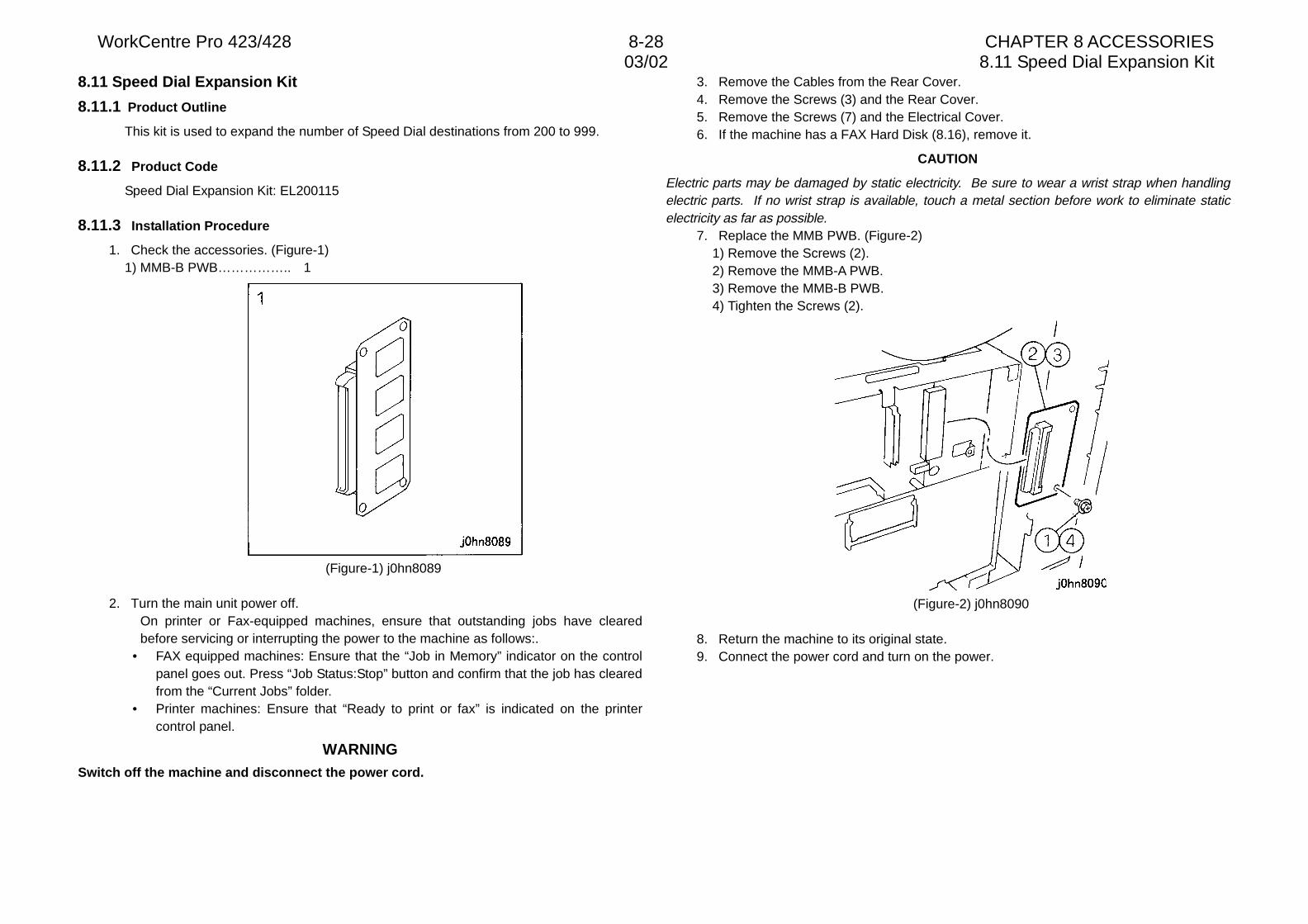
WorkCentre Pro 423/428 8-28 CHAPTER 8 ACCESSORIES03/02 8.11 Speed Dial Expansion Kit
8.11 Speed Dial Expansion Kit
8.11.1 Product Outline
This kit is used to expand the number of Speed Dial destinations from 200 to 999.
8.11.2 Product Code
Speed Dial Expansion Kit: EL200115
8.11.3 Installation Procedure
1. Check the accessories. (Figure-1)1) MMB-B PWB…………….. 1
(Figure-1) j0hn8089
2. Turn the main unit power off.On printer or Fax-equipped machines, ensure that outstanding jobs have clearedbefore servicing or interrupting the power to the machine as follows:.
• FAX equipped machines: Ensure that the “Job in Memory” indicator on the controlpanel goes out. Press “Job Status:Stop” button and confirm that the job has clearedfrom the “Current Jobs” folder.
• Printer machines: Ensure that “Ready to print or fax” is indicated on the printercontrol panel.
WARNINGSwitch off the machine and disconnect the power cord.
3. Remove the Cables from the Rear Cover.4. Remove the Screws (3) and the Rear Cover.5. Remove the Screws (7) and the Electrical Cover.6. If the machine has a FAX Hard Disk (8.16), remove it.
CAUTION
Electric parts may be damaged by static electricity. Be sure to wear a wrist strap when handlingelectric parts. If no wrist strap is available, touch a metal section before work to eliminate staticelectricity as far as possible.
7. Replace the MMB PWB. (Figure-2)1) Remove the Screws (2).2) Remove the MMB-A PWB.3) Remove the MMB-B PWB.4) Tighten the Screws (2).
(Figure-2) j0hn8090
8. Return the machine to its original state.9. Connect the power cord and turn on the power.
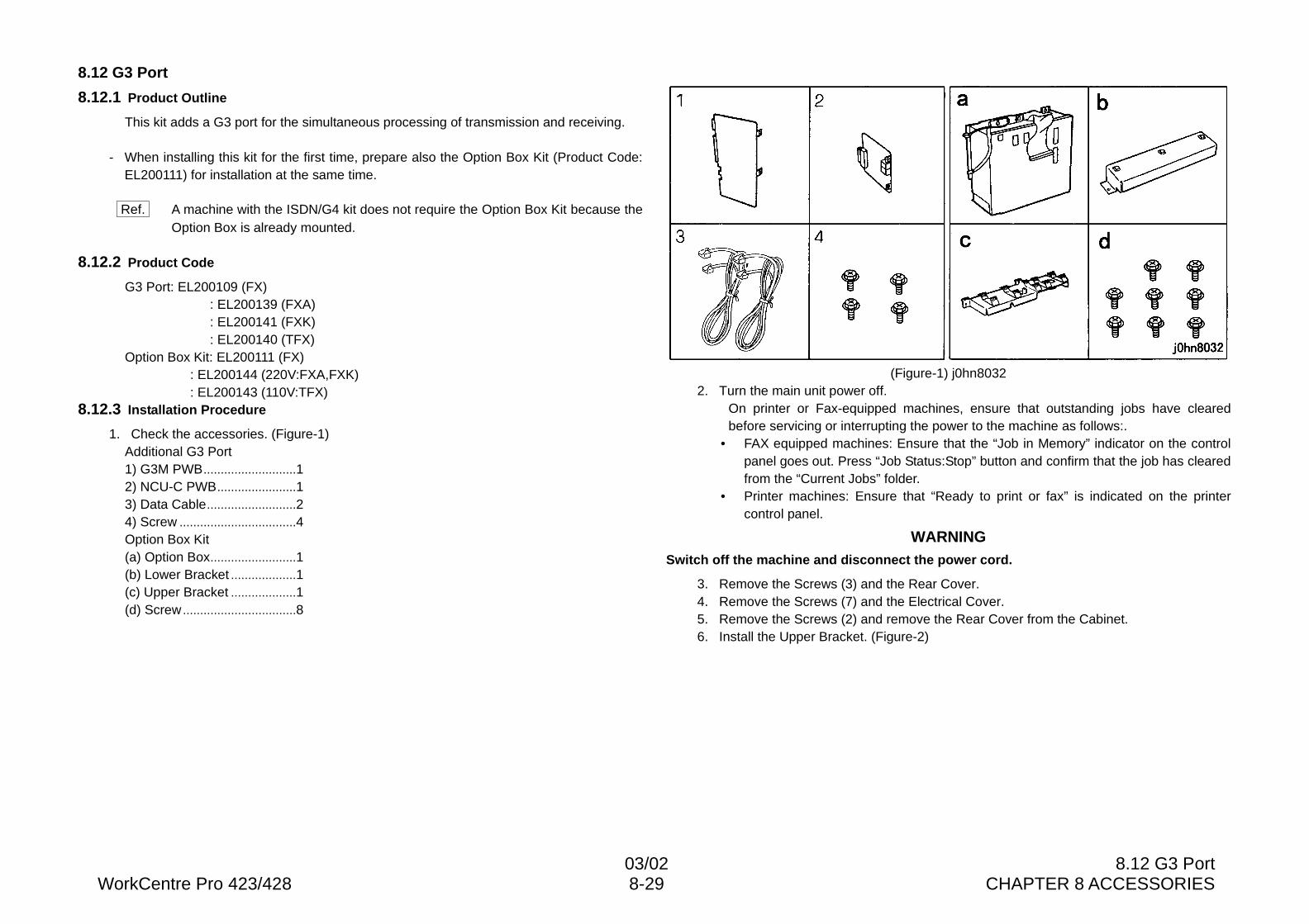
03/02 8.12 G3 PortWorkCentre Pro 423/428 8-29 CHAPTER 8 ACCESSORIES
8.12 G3 Port
8.12.1 Product Outline
This kit adds a G3 port for the simultaneous processing of transmission and receiving.
- When installing this kit for the first time, prepare also the Option Box Kit (Product Code:EL200111) for installation at the same time.
Ref. A machine with the ISDN/G4 kit does not require the Option Box Kit because theOption Box is already mounted.
8.12.2 Product Code
G3 Port: EL200109 (FX): EL200139 (FXA): EL200141 (FXK): EL200140 (TFX)
Option Box Kit: EL200111 (FX): EL200144 (220V:FXA,FXK): EL200143 (110V:TFX)
8.12.3 Installation Procedure
1. Check the accessories. (Figure-1)Additional G3 Port1) G3M PWB...........................12) NCU-C PWB.......................13) Data Cable..........................24) Screw ..................................4Option Box Kit(a) Option Box.........................1(b) Lower Bracket ...................1(c) Upper Bracket ...................1(d) Screw.................................8
(Figure-1) j0hn80322. Turn the main unit power off.
On printer or Fax-equipped machines, ensure that outstanding jobs have clearedbefore servicing or interrupting the power to the machine as follows:.
• FAX equipped machines: Ensure that the “Job in Memory” indicator on the controlpanel goes out. Press “Job Status:Stop” button and confirm that the job has clearedfrom the “Current Jobs” folder.
• Printer machines: Ensure that “Ready to print or fax” is indicated on the printercontrol panel.
WARNINGSwitch off the machine and disconnect the power cord.
3. Remove the Screws (3) and the Rear Cover.4. Remove the Screws (7) and the Electrical Cover.5. Remove the Screws (2) and remove the Rear Cover from the Cabinet.6. Install the Upper Bracket. (Figure-2)
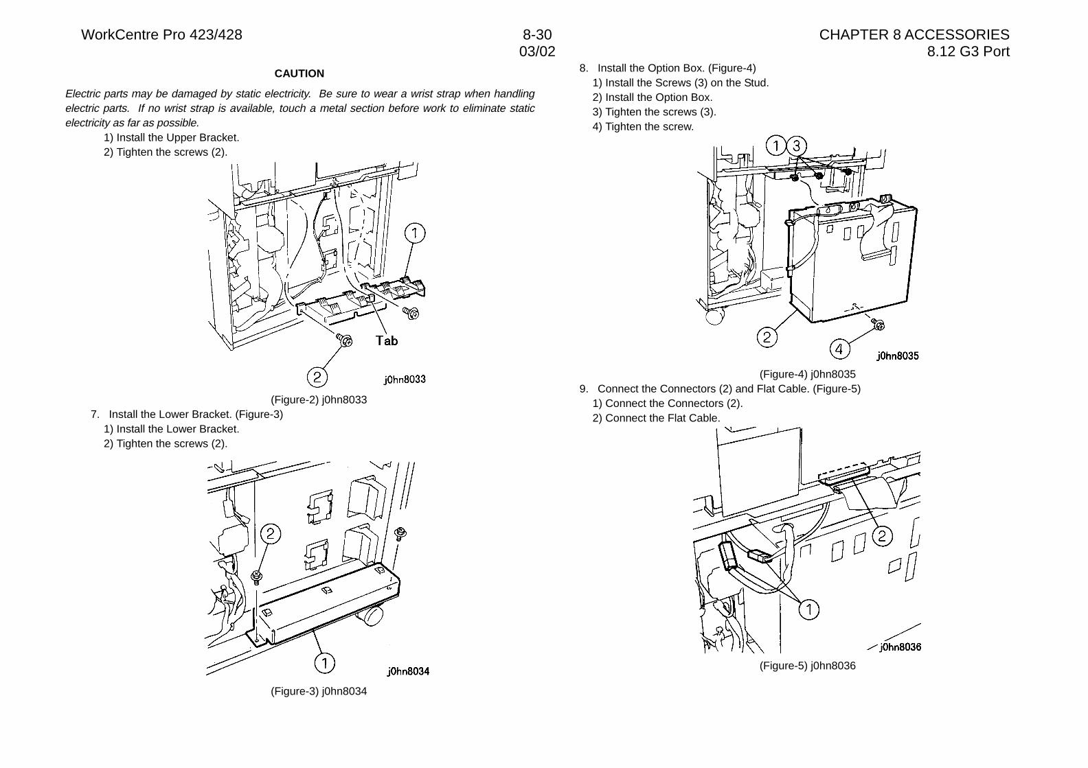
WorkCentre Pro 423/428 8-30 CHAPTER 8 ACCESSORIES03/02 8.12 G3 Port
CAUTION
Electric parts may be damaged by static electricity. Be sure to wear a wrist strap when handlingelectric parts. If no wrist strap is available, touch a metal section before work to eliminate staticelectricity as far as possible.
1) Install the Upper Bracket.2) Tighten the screws (2).
(Figure-2) j0hn80337. Install the Lower Bracket. (Figure-3)
1) Install the Lower Bracket.2) Tighten the screws (2).
(Figure-3) j0hn8034
8. Install the Option Box. (Figure-4)1) Install the Screws (3) on the Stud.2) Install the Option Box.3) Tighten the screws (3).4) Tighten the screw.
(Figure-4) j0hn80359. Connect the Connectors (2) and Flat Cable. (Figure-5)
1) Connect the Connectors (2).2) Connect the Flat Cable.
(Figure-5) j0hn8036
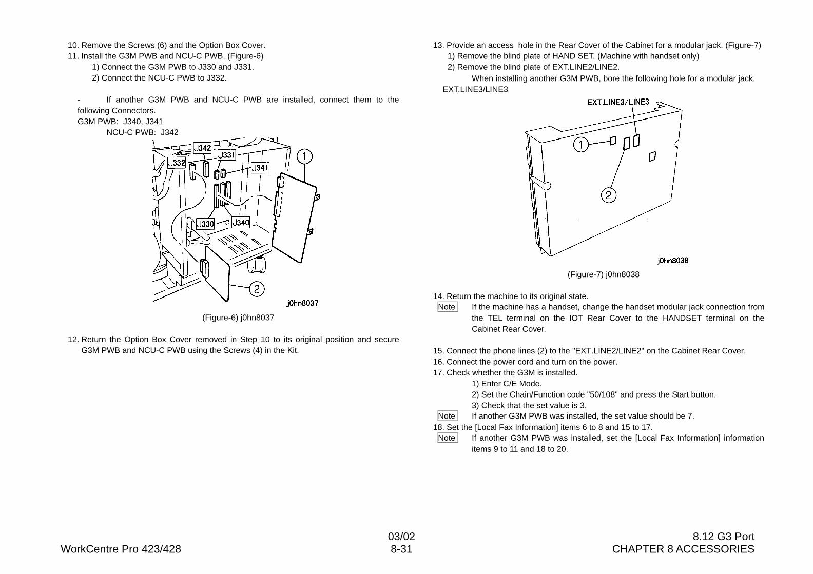
03/02 8.12 G3 PortWorkCentre Pro 423/428 8-31 CHAPTER 8 ACCESSORIES
10. Remove the Screws (6) and the Option Box Cover.11. Install the G3M PWB and NCU-C PWB. (Figure-6)
1) Connect the G3M PWB to J330 and J331.2) Connect the NCU-C PWB to J332.
- If another G3M PWB and NCU-C PWB are installed, connect them to thefollowing Connectors.G3M PWB: J340, J341
NCU-C PWB: J342
(Figure-6) j0hn8037
12. Return the Option Box Cover removed in Step 10 to its original position and secureG3M PWB and NCU-C PWB using the Screws (4) in the Kit.
13. Provide an access hole in the Rear Cover of the Cabinet for a modular jack. (Figure-7)1) Remove the blind plate of HAND SET. (Machine with handset only)2) Remove the blind plate of EXT.LINE2/LINE2.
When installing another G3M PWB, bore the following hole for a modular jack.EXT.LINE3/LINE3
(Figure-7) j0hn8038
14. Return the machine to its original state.Note If the machine has a handset, change the handset modular jack connection from
the TEL terminal on the IOT Rear Cover to the HANDSET terminal on theCabinet Rear Cover.
15. Connect the phone lines (2) to the "EXT.LINE2/LINE2" on the Cabinet Rear Cover.16. Connect the power cord and turn on the power.17. Check whether the G3M is installed.
1) Enter C/E Mode.2) Set the Chain/Function code "50/108" and press the Start button.3) Check that the set value is 3.
Note If another G3M PWB was installed, the set value should be 7.18. Set the [Local Fax Information] items 6 to 8 and 15 to 17.
Note If another G3M PWB was installed, set the [Local Fax Information] informationitems 9 to 11 and 18 to 20.
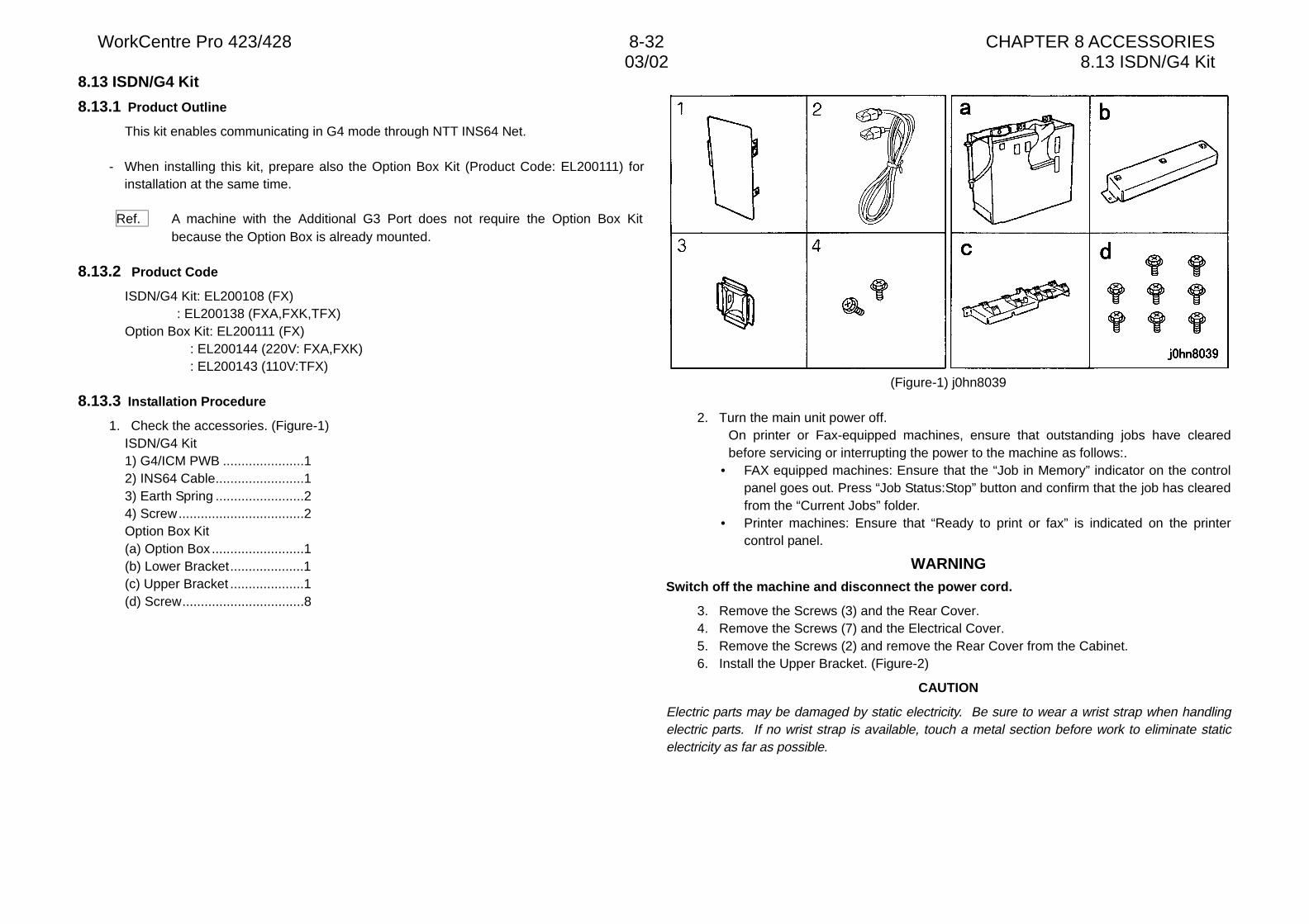
WorkCentre Pro 423/428 8-32 CHAPTER 8 ACCESSORIES03/02 8.13 ISDN/G4 Kit
8.13 ISDN/G4 Kit
8.13.1 Product Outline
This kit enables communicating in G4 mode through NTT INS64 Net.
- When installing this kit, prepare also the Option Box Kit (Product Code: EL200111) forinstallation at the same time.
Ref. A machine with the Additional G3 Port does not require the Option Box Kitbecause the Option Box is already mounted.
8.13.2 Product Code
ISDN/G4 Kit: EL200108 (FX): EL200138 (FXA,FXK,TFX)
Option Box Kit: EL200111 (FX): EL200144 (220V: FXA,FXK): EL200143 (110V:TFX)
8.13.3 Installation Procedure
1. Check the accessories. (Figure-1)ISDN/G4 Kit1) G4/ICM PWB ......................12) INS64 Cable........................13) Earth Spring ........................24) Screw..................................2Option Box Kit(a) Option Box .........................1(b) Lower Bracket....................1(c) Upper Bracket ....................1(d) Screw.................................8
(Figure-1) j0hn8039
2. Turn the main unit power off.On printer or Fax-equipped machines, ensure that outstanding jobs have clearedbefore servicing or interrupting the power to the machine as follows:.
• FAX equipped machines: Ensure that the “Job in Memory” indicator on the controlpanel goes out. Press “Job Status:Stop” button and confirm that the job has clearedfrom the “Current Jobs” folder.
• Printer machines: Ensure that “Ready to print or fax” is indicated on the printercontrol panel.
WARNINGSwitch off the machine and disconnect the power cord.
3. Remove the Screws (3) and the Rear Cover.4. Remove the Screws (7) and the Electrical Cover.5. Remove the Screws (2) and remove the Rear Cover from the Cabinet.6. Install the Upper Bracket. (Figure-2)
CAUTION
Electric parts may be damaged by static electricity. Be sure to wear a wrist strap when handlingelectric parts. If no wrist strap is available, touch a metal section before work to eliminate staticelectricity as far as possible.
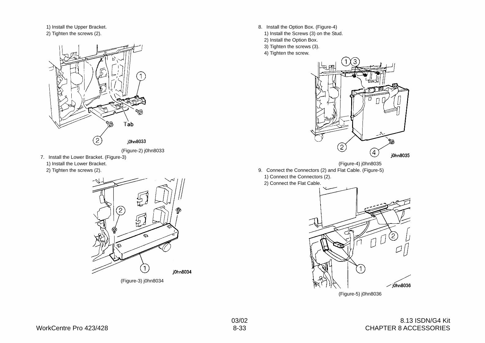
03/02 8.13 ISDN/G4 KitWorkCentre Pro 423/428 8-33 CHAPTER 8 ACCESSORIES
1) Install the Upper Bracket.2) Tighten the screws (2).
(Figure-2) j0hn80337. Install the Lower Bracket. (Figure-3)
1) Install the Lower Bracket.2) Tighten the screws (2).
(Figure-3) j0hn8034
8. Install the Option Box. (Figure-4)1) Install the Screws (3) on the Stud.2) Install the Option Box.3) Tighten the screws (3).4) Tighten the screw.
(Figure-4) j0hn80359. Connect the Connectors (2) and Flat Cable. (Figure-5)
1) Connect the Connectors (2).2) Connect the Flat Cable.
(Figure-5) j0hn8036
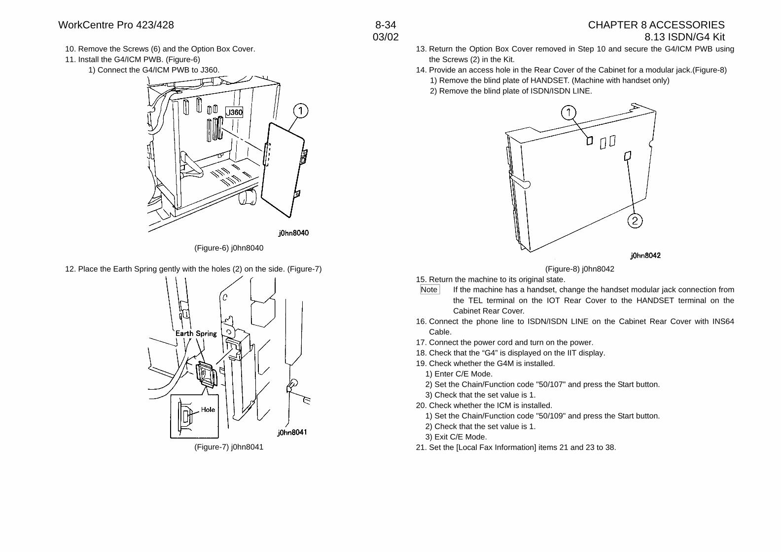
WorkCentre Pro 423/428 8-34 CHAPTER 8 ACCESSORIES03/02 8.13 ISDN/G4 Kit
10. Remove the Screws (6) and the Option Box Cover.11. Install the G4/ICM PWB. (Figure-6)
1) Connect the G4/ICM PWB to J360.
(Figure-6) j0hn8040
12. Place the Earth Spring gently with the holes (2) on the side. (Figure-7)
(Figure-7) j0hn8041
13. Return the Option Box Cover removed in Step 10 and secure the G4/ICM PWB usingthe Screws (2) in the Kit.
14. Provide an access hole in the Rear Cover of the Cabinet for a modular jack.(Figure-8)1) Remove the blind plate of HANDSET. (Machine with handset only)2) Remove the blind plate of ISDN/ISDN LINE.
(Figure-8) j0hn804215. Return the machine to its original state.
Note If the machine has a handset, change the handset modular jack connection fromthe TEL terminal on the IOT Rear Cover to the HANDSET terminal on theCabinet Rear Cover.
16. Connect the phone line to ISDN/ISDN LINE on the Cabinet Rear Cover with INS64Cable.
17. Connect the power cord and turn on the power.18. Check that the “G4” is displayed on the IIT display.19. Check whether the G4M is installed.
1) Enter C/E Mode.2) Set the Chain/Function code "50/107" and press the Start button.3) Check that the set value is 1.
20. Check whether the ICM is installed.1) Set the Chain/Function code "50/109" and press the Start button.2) Check that the set value is 1.3) Exit C/E Mode.
21. Set the [Local Fax Information] items 21 and 23 to 38.
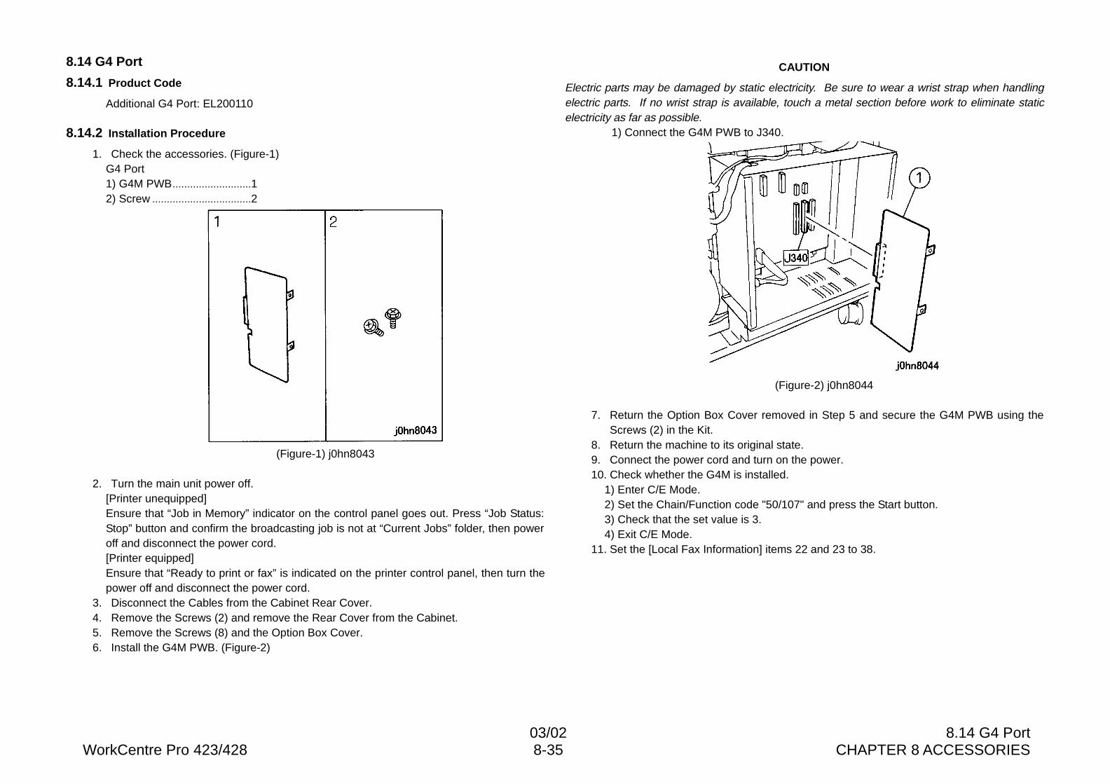
03/02 8.14 G4 PortWorkCentre Pro 423/428 8-35 CHAPTER 8 ACCESSORIES
8.14 G4 Port
8.14.1 Product Code
Additional G4 Port: EL200110
8.14.2 Installation Procedure
1. Check the accessories. (Figure-1)G4 Port1) G4M PWB...........................12) Screw ..................................2
(Figure-1) j0hn8043
2. Turn the main unit power off.[Printer unequipped]Ensure that “Job in Memory” indicator on the control panel goes out. Press “Job Status:Stop” button and confirm the broadcasting job is not at “Current Jobs” folder, then poweroff and disconnect the power cord.[Printer equipped]Ensure that “Ready to print or fax” is indicated on the printer control panel, then turn thepower off and disconnect the power cord.
3. Disconnect the Cables from the Cabinet Rear Cover.4. Remove the Screws (2) and remove the Rear Cover from the Cabinet.5. Remove the Screws (8) and the Option Box Cover.6. Install the G4M PWB. (Figure-2)
CAUTION
Electric parts may be damaged by static electricity. Be sure to wear a wrist strap when handlingelectric parts. If no wrist strap is available, touch a metal section before work to eliminate staticelectricity as far as possible.
1) Connect the G4M PWB to J340.
(Figure-2) j0hn8044
7. Return the Option Box Cover removed in Step 5 and secure the G4M PWB using theScrews (2) in the Kit.
8. Return the machine to its original state.9. Connect the power cord and turn on the power.10. Check whether the G4M is installed.
1) Enter C/E Mode.2) Set the Chain/Function code "50/107" and press the Start button.3) Check that the set value is 3.4) Exit C/E Mode.
11. Set the [Local Fax Information] items 22 and 23 to 38.
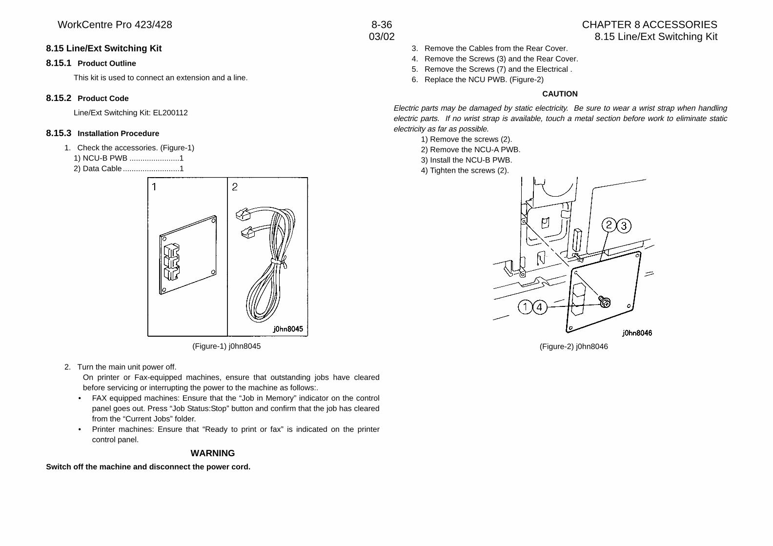
WorkCentre Pro 423/428 8-36 CHAPTER 8 ACCESSORIES03/02 8.15 Line/Ext Switching Kit
8.15 Line/Ext Switching Kit
8.15.1 Product Outline
This kit is used to connect an extension and a line.
8.15.2 Product Code
Line/Ext Switching Kit: EL200112
8.15.3 Installation Procedure
1. Check the accessories. (Figure-1)1) NCU-B PWB .......................12) Data Cable ..........................1
(Figure-1) j0hn8045
2. Turn the main unit power off.On printer or Fax-equipped machines, ensure that outstanding jobs have clearedbefore servicing or interrupting the power to the machine as follows:.
• FAX equipped machines: Ensure that the “Job in Memory” indicator on the controlpanel goes out. Press “Job Status:Stop” button and confirm that the job has clearedfrom the “Current Jobs” folder.
• Printer machines: Ensure that “Ready to print or fax” is indicated on the printercontrol panel.
WARNINGSwitch off the machine and disconnect the power cord.
3. Remove the Cables from the Rear Cover.4. Remove the Screws (3) and the Rear Cover.5. Remove the Screws (7) and the Electrical .6. Replace the NCU PWB. (Figure-2)
CAUTION
Electric parts may be damaged by static electricity. Be sure to wear a wrist strap when handlingelectric parts. If no wrist strap is available, touch a metal section before work to eliminate staticelectricity as far as possible.
1) Remove the screws (2).2) Remove the NCU-A PWB.3) Install the NCU-B PWB.4) Tighten the screws (2).
(Figure-2) j0hn8046
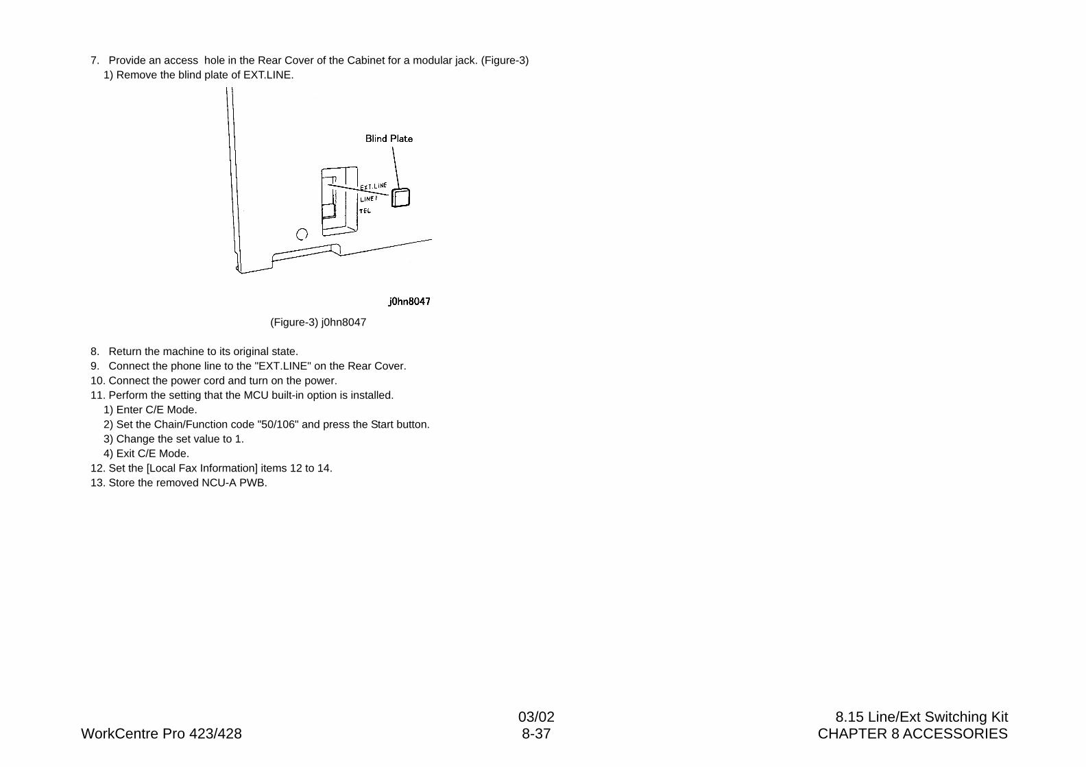
03/02 8.15 Line/Ext Switching KitWorkCentre Pro 423/428 8-37 CHAPTER 8 ACCESSORIES
7. Provide an access hole in the Rear Cover of the Cabinet for a modular jack. (Figure-3)1) Remove the blind plate of EXT.LINE.
(Figure-3) j0hn8047
8. Return the machine to its original state.9. Connect the phone line to the "EXT.LINE" on the Rear Cover.10. Connect the power cord and turn on the power.11. Perform the setting that the MCU built-in option is installed.
1) Enter C/E Mode.2) Set the Chain/Function code "50/106" and press the Start button.3) Change the set value to 1.4) Exit C/E Mode.
12. Set the [Local Fax Information] items 12 to 14.13. Store the removed NCU-A PWB.
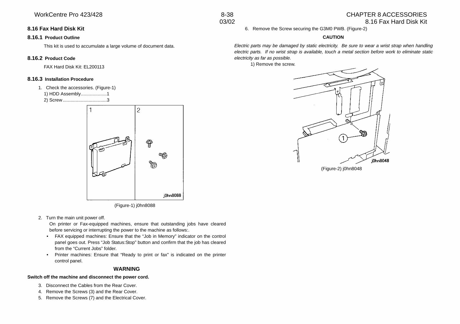
WorkCentre Pro 423/428 8-38 CHAPTER 8 ACCESSORIES03/02 8.16 Fax Hard Disk Kit
8.16 Fax Hard Disk Kit
8.16.1 Product Outline
This kit is used to accumulate a large volume of document data.
8.16.2 Product Code
FAX Hard Disk Kit: EL200113
8.16.3 Installation Procedure
1. Check the accessories. (Figure-1)1) HDD Assembly....................12) Screw..................................3
(Figure-1) j0hn8088
2. Turn the main unit power off.On printer or Fax-equipped machines, ensure that outstanding jobs have clearedbefore servicing or interrupting the power to the machine as follows:.
• FAX equipped machines: Ensure that the “Job in Memory” indicator on the controlpanel goes out. Press “Job Status:Stop” button and confirm that the job has clearedfrom the “Current Jobs” folder.
• Printer machines: Ensure that “Ready to print or fax” is indicated on the printercontrol panel.
WARNINGSwitch off the machine and disconnect the power cord.
3. Disconnect the Cables from the Rear Cover.4. Remove the Screws (3) and the Rear Cover.5. Remove the Screws (7) and the Electrical Cover.
6. Remove the Screw securing the G3M0 PWB. (Figure-2)
CAUTION
Electric parts may be damaged by static electricity. Be sure to wear a wrist strap when handlingelectric parts. If no wrist strap is available, touch a metal section before work to eliminate staticelectricity as far as possible.
1) Remove the screw.
(Figure-2) j0hn8048
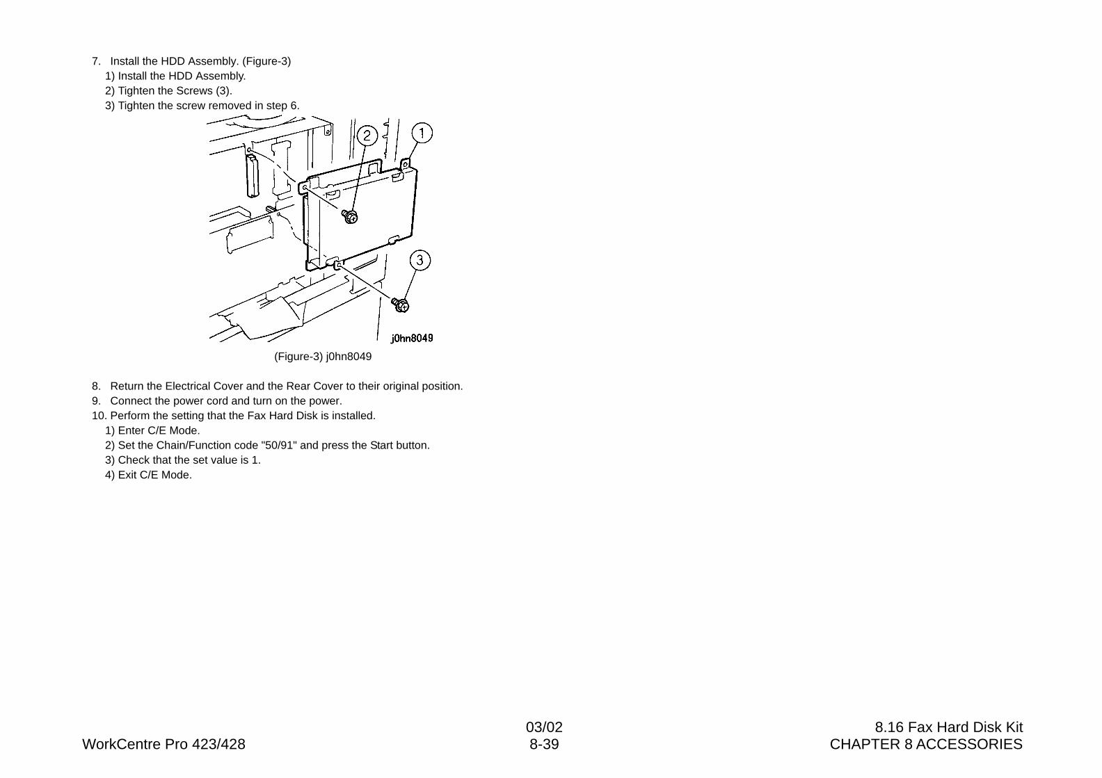
03/02 8.16 Fax Hard Disk KitWorkCentre Pro 423/428 8-39 CHAPTER 8 ACCESSORIES
7. Install the HDD Assembly. (Figure-3)1) Install the HDD Assembly.2) Tighten the Screws (3).3) Tighten the screw removed in step 6.
(Figure-3) j0hn8049
8. Return the Electrical Cover and the Rear Cover to their original position.9. Connect the power cord and turn on the power.10. Perform the setting that the Fax Hard Disk is installed.
1) Enter C/E Mode.2) Set the Chain/Function code "50/91" and press the Start button.3) Check that the set value is 1.4) Exit C/E Mode.
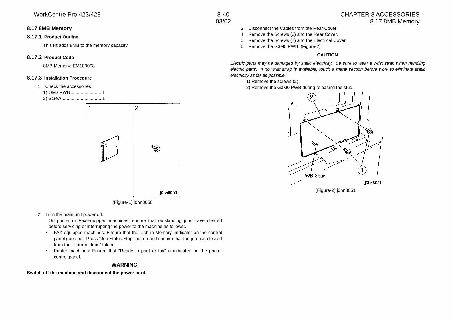
WorkCentre Pro 423/428 8-40 CHAPTER 8 ACCESSORIES03/02 8.17 8MB Memory
8.17 8MB Memory
8.17.1 Product Outline
This kit adds 8MB to the memory capacity.
8.17.2 Product Code
8MB Memory: EM100008
8.17.3 Installation Procedure
1. Check the accessories.1) OM3 PWB........................ 12) Screw............................... 1
(Figure-1) j0hn8050
2. Turn the main unit power off.On printer or Fax-equipped machines, ensure that outstanding jobs have clearedbefore servicing or interrupting the power to the machine as follows:.
• FAX equipped machines: Ensure that the “Job in Memory” indicator on the controlpanel goes out. Press “Job Status:Stop” button and confirm that the job has clearedfrom the “Current Jobs” folder.
• Printer machines: Ensure that “Ready to print or fax” is indicated on the printercontrol panel.
WARNINGSwitch off the machine and disconnect the power cord.
3. Disconnect the Cables from the Rear Cover.4. Remove the Screws (3) and the Rear Cover.5. Remove the Screws (7) and the Electrical Cover.6. Remove the G3M0 PWB. (Figure-2)
CAUTION
Electric parts may be damaged by static electricity. Be sure to wear a wrist strap when handlingelectric parts. If no wrist strap is available, touch a metal section before work to eliminate staticelectricity as far as possible.
1) Remove the screws (2).2) Remove the G3M0 PWB during releasing the stud.
(Figure-2) j0hn8051
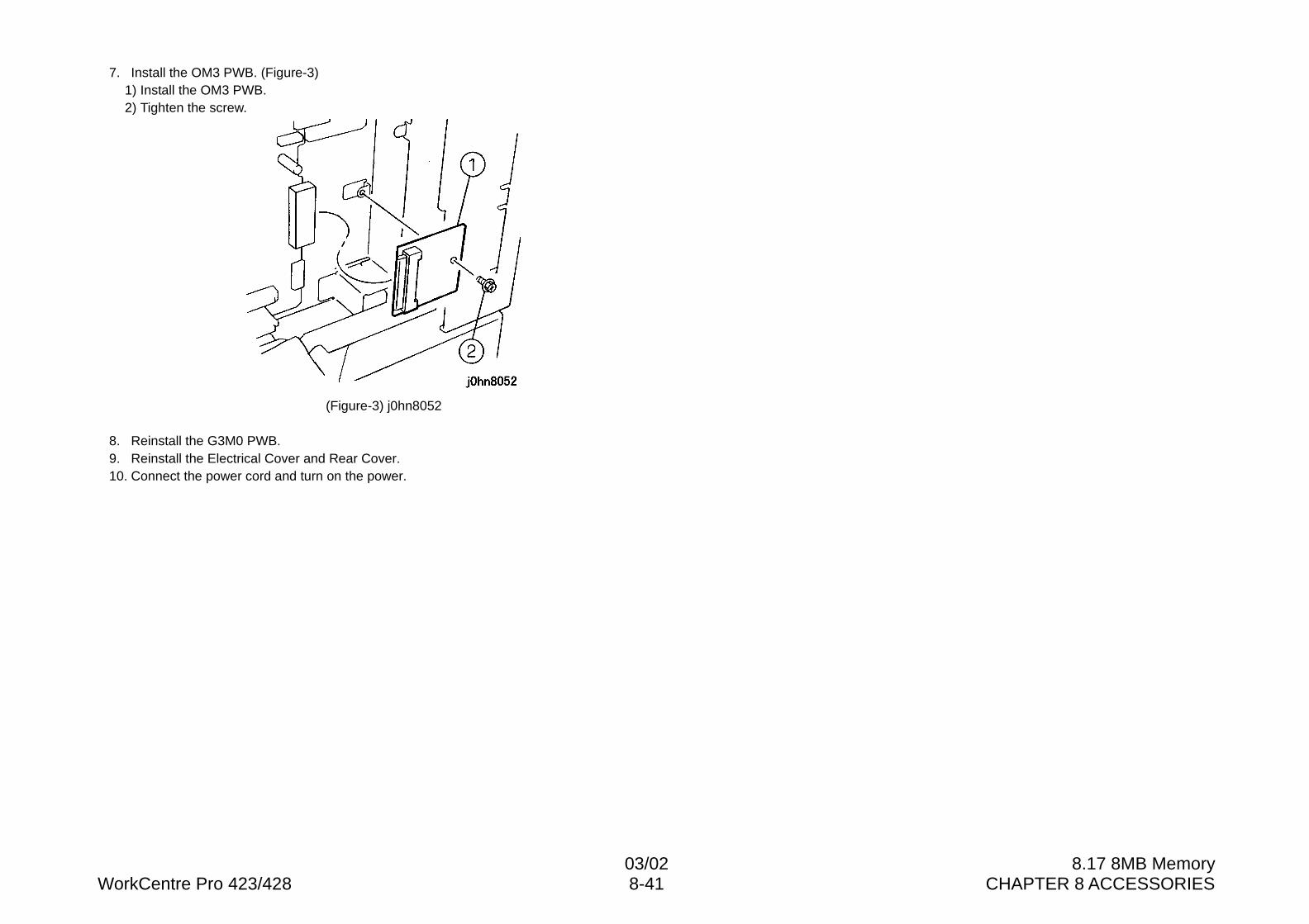
03/02 8.17 8MB MemoryWorkCentre Pro 423/428 8-41 CHAPTER 8 ACCESSORIES
7. Install the OM3 PWB. (Figure-3)1) Install the OM3 PWB.2) Tighten the screw.
(Figure-3) j0hn8052
8. Reinstall the G3M0 PWB.9. Reinstall the Electrical Cover and Rear Cover.10. Connect the power cord and turn on the power.
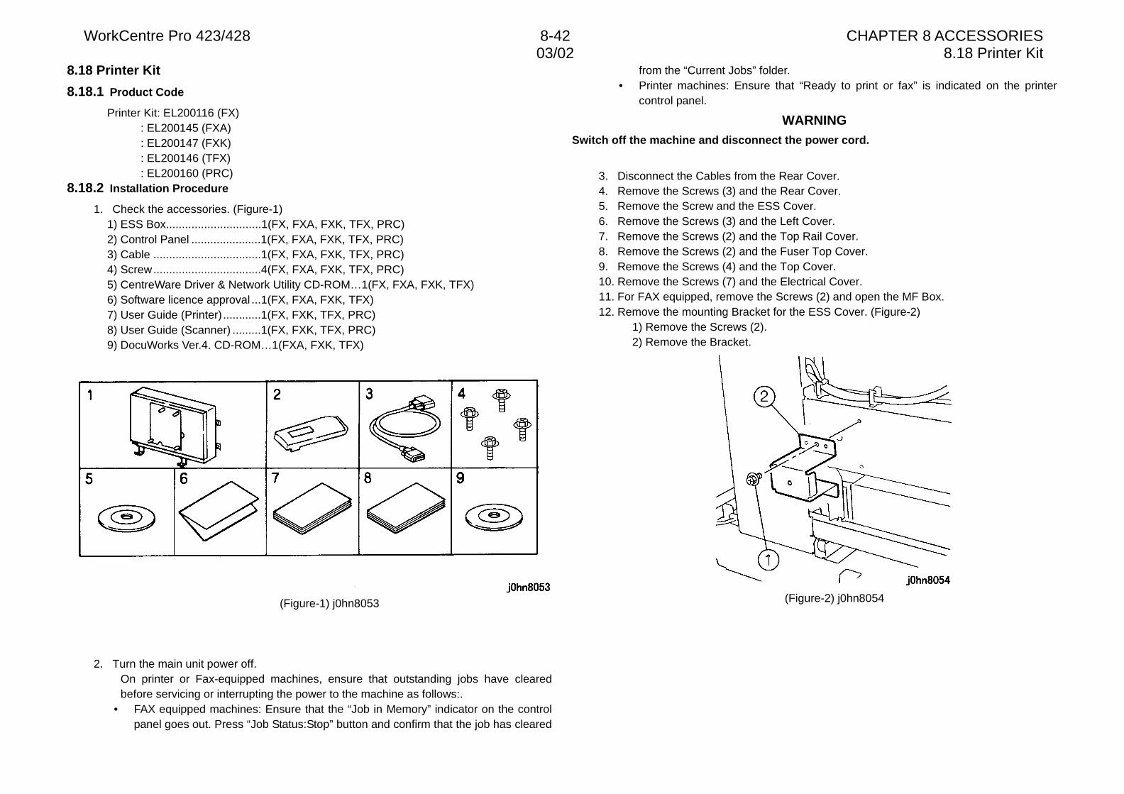
WorkCentre Pro 423/428 8-42 CHAPTER 8 ACCESSORIES03/02 8.18 Printer Kit
8.18 Printer Kit
8.18.1 Product Code
Printer Kit: EL200116 (FX): EL200145 (FXA): EL200147 (FXK): EL200146 (TFX): EL200160 (PRC)
8.18.2 Installation Procedure
1. Check the accessories. (Figure-1)1) ESS Box..............................1(FX, FXA, FXK, TFX, PRC)2) Control Panel ......................1(FX, FXA, FXK, TFX, PRC)3) Cable ..................................1(FX, FXA, FXK, TFX, PRC)4) Screw..................................4(FX, FXA, FXK, TFX, PRC)5) CentreWare Driver & Network Utility CD-ROM…1(FX, FXA, FXK, TFX)6) Software licence approval ...1(FX, FXA, FXK, TFX)7) User Guide (Printer) ............1(FX, FXK, TFX, PRC)8) User Guide (Scanner) .........1(FX, FXK, TFX, PRC)9) DocuWorks Ver.4. CD-ROM…1(FXA, FXK, TFX)
(Figure-1) j0hn8053
2. Turn the main unit power off.On printer or Fax-equipped machines, ensure that outstanding jobs have clearedbefore servicing or interrupting the power to the machine as follows:.
• FAX equipped machines: Ensure that the “Job in Memory” indicator on the controlpanel goes out. Press “Job Status:Stop” button and confirm that the job has cleared
from the “Current Jobs” folder.• Printer machines: Ensure that “Ready to print or fax” is indicated on the printer
control panel.
WARNINGSwitch off the machine and disconnect the power cord.
3. Disconnect the Cables from the Rear Cover.4. Remove the Screws (3) and the Rear Cover.5. Remove the Screw and the ESS Cover.6. Remove the Screws (3) and the Left Cover.7. Remove the Screws (2) and the Top Rail Cover.8. Remove the Screws (2) and the Fuser Top Cover.9. Remove the Screws (4) and the Top Cover.10. Remove the Screws (7) and the Electrical Cover.11. For FAX equipped, remove the Screws (2) and open the MF Box.12. Remove the mounting Bracket for the ESS Cover. (Figure-2)
1) Remove the Screws (2).2) Remove the Bracket.
(Figure-2) j0hn8054
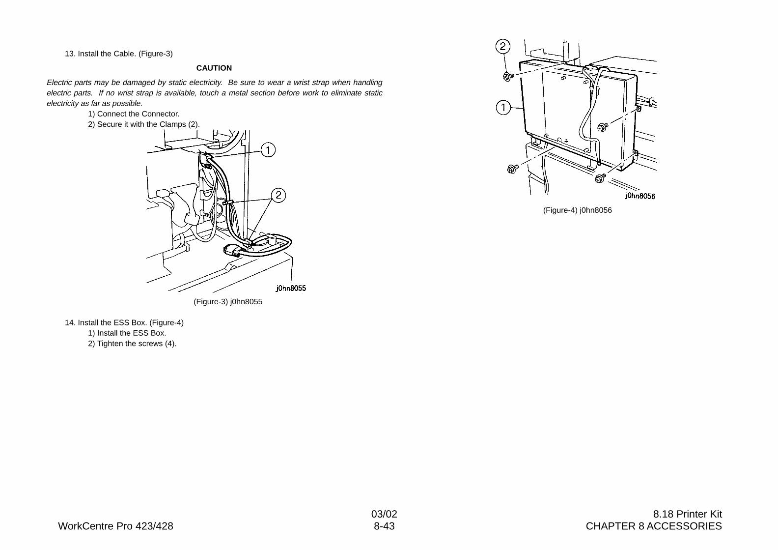
03/02 8.18 Printer KitWorkCentre Pro 423/428 8-43 CHAPTER 8 ACCESSORIES
13. Install the Cable. (Figure-3)
CAUTION
Electric parts may be damaged by static electricity. Be sure to wear a wrist strap when handlingelectric parts. If no wrist strap is available, touch a metal section before work to eliminate staticelectricity as far as possible.
1) Connect the Connector.2) Secure it with the Clamps (2).
(Figure-3) j0hn8055
14. Install the ESS Box. (Figure-4)1) Install the ESS Box.2) Tighten the screws (4).
(Figure-4) j0hn8056
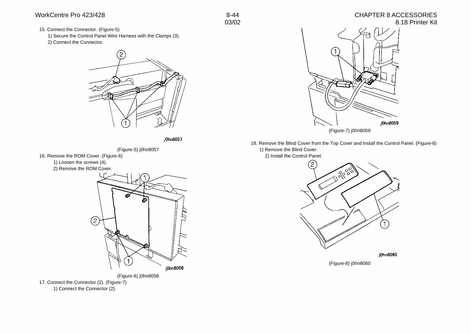
WorkCentre Pro 423/428 8-44 CHAPTER 8 ACCESSORIES03/02 8.18 Printer Kit
15. Connect the Connector. (Figure-5)1) Secure the Control Panel Wire Harness with the Clamps (3).2) Connect the Connector.
(Figure-5) j0hn805716. Remove the ROM Cover. (Figure-6)
1) Loosen the screws (4).2) Remove the ROM Cover.
(Figure-6) j0hn805817. Connect the Connector (2). (Figure-7)
1) Connect the Connector (2).
(Figure-7) j0hn8059
18. Remove the Blind Cover from the Top Cover and install the Control Panel. (Figure-8)1) Remove the Blind Cover.
2) Install the Control Panel.
(Figure-8) j0hn8060
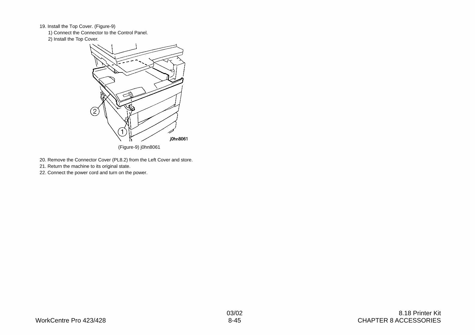
03/02 8.18 Printer KitWorkCentre Pro 423/428 8-45 CHAPTER 8 ACCESSORIES
19. Install the Top Cover. (Figure-9)1) Connect the Connector to the Control Panel.2) Install the Top Cover.
(Figure-9) j0hn8061
20. Remove the Connector Cover (PL8.2) from the Left Cover and store.21. Return the machine to its original state.22. Connect the power cord and turn on the power.
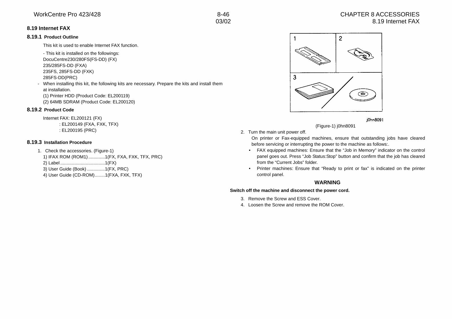
WorkCentre Pro 423/428 8-46 CHAPTER 8 ACCESSORIES03/02 8.19 Internet FAX
8.19 Internet FAX
8.19.1 Product Outline
This kit is used to enable Internet FAX function.
- This kit is installed on the followings:DocuCentre230/280FS(FS-DD) (FX)235/285FS-DD (FXA)235FS, 285FS-DD (FXK)285FS-DD(PRC)
- When installing this kit, the following kits are necessary. Prepare the kits and install themat installation.(1) Printer HDD (Product Code: EL200119)(2) 64MB SDRAM (Product Code: EL200120)
8.19.2 Product Code
Internet FAX: EL200121 (FX): EL200149 (FXA, FXK, TFX): EL200195 (PRC)
8.19.3 Installation Procedure
1. Check the accessories. (Figure-1)1) IFAX ROM (ROM1) .............1(FX, FXA, FXK, TFX, PRC)2) Label ...................................1(FX)3) User Guide (Book) ..............1(FX, PRC)4) User Guide (CD-ROM)........1(FXA, FXK, TFX)
(Figure-1) j0hn80912. Turn the main unit power off.
On printer or Fax-equipped machines, ensure that outstanding jobs have clearedbefore servicing or interrupting the power to the machine as follows:.
• FAX equipped machines: Ensure that the “Job in Memory” indicator on the controlpanel goes out. Press “Job Status:Stop” button and confirm that the job has clearedfrom the “Current Jobs” folder.
• Printer machines: Ensure that “Ready to print or fax” is indicated on the printercontrol panel.
WARNINGSwitch off the machine and disconnect the power cord.
3. Remove the Screw and ESS Cover.4. Loosen the Screw and remove the ROM Cover.
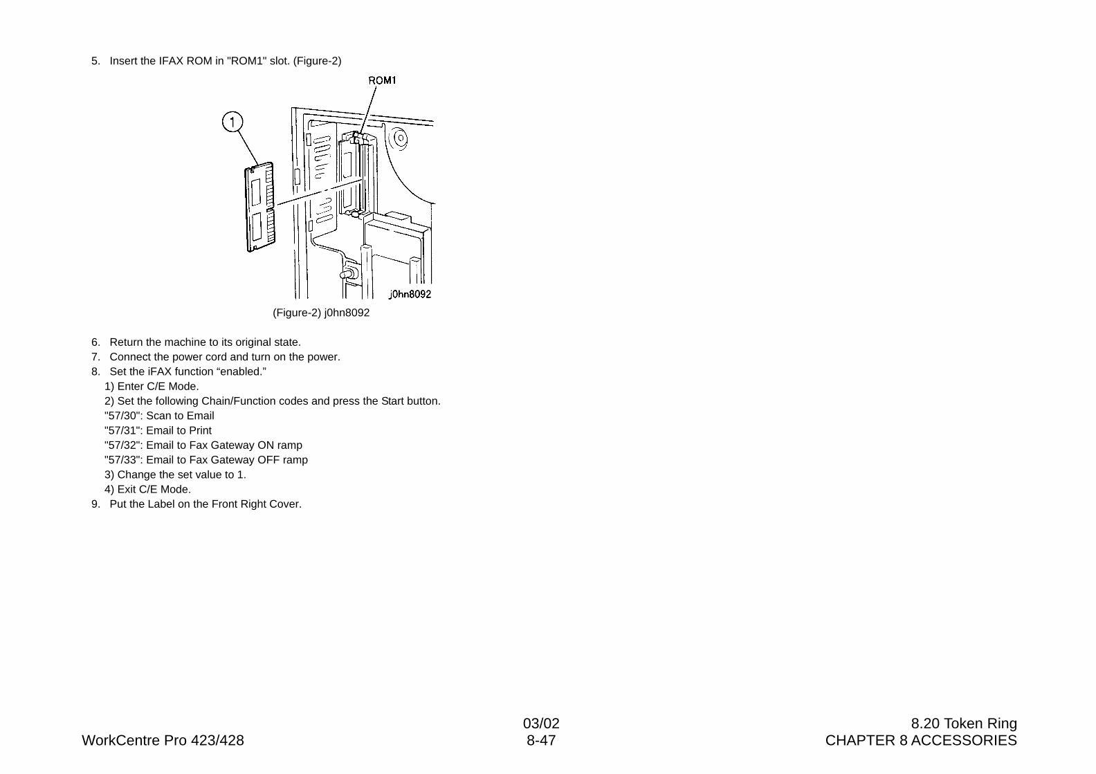
03/02 8.20 Token RingWorkCentre Pro 423/428 8-47 CHAPTER 8 ACCESSORIES
5. Insert the IFAX ROM in "ROM1" slot. (Figure-2)
(Figure-2) j0hn8092
6. Return the machine to its original state.7. Connect the power cord and turn on the power.8. Set the iFAX function “enabled.”
1) Enter C/E Mode.2) Set the following Chain/Function codes and press the Start button."57/30": Scan to Email"57/31": Email to Print"57/32": Email to Fax Gateway ON ramp"57/33": Email to Fax Gateway OFF ramp3) Change the set value to 1.4) Exit C/E Mode.
9. Put the Label on the Front Right Cover.
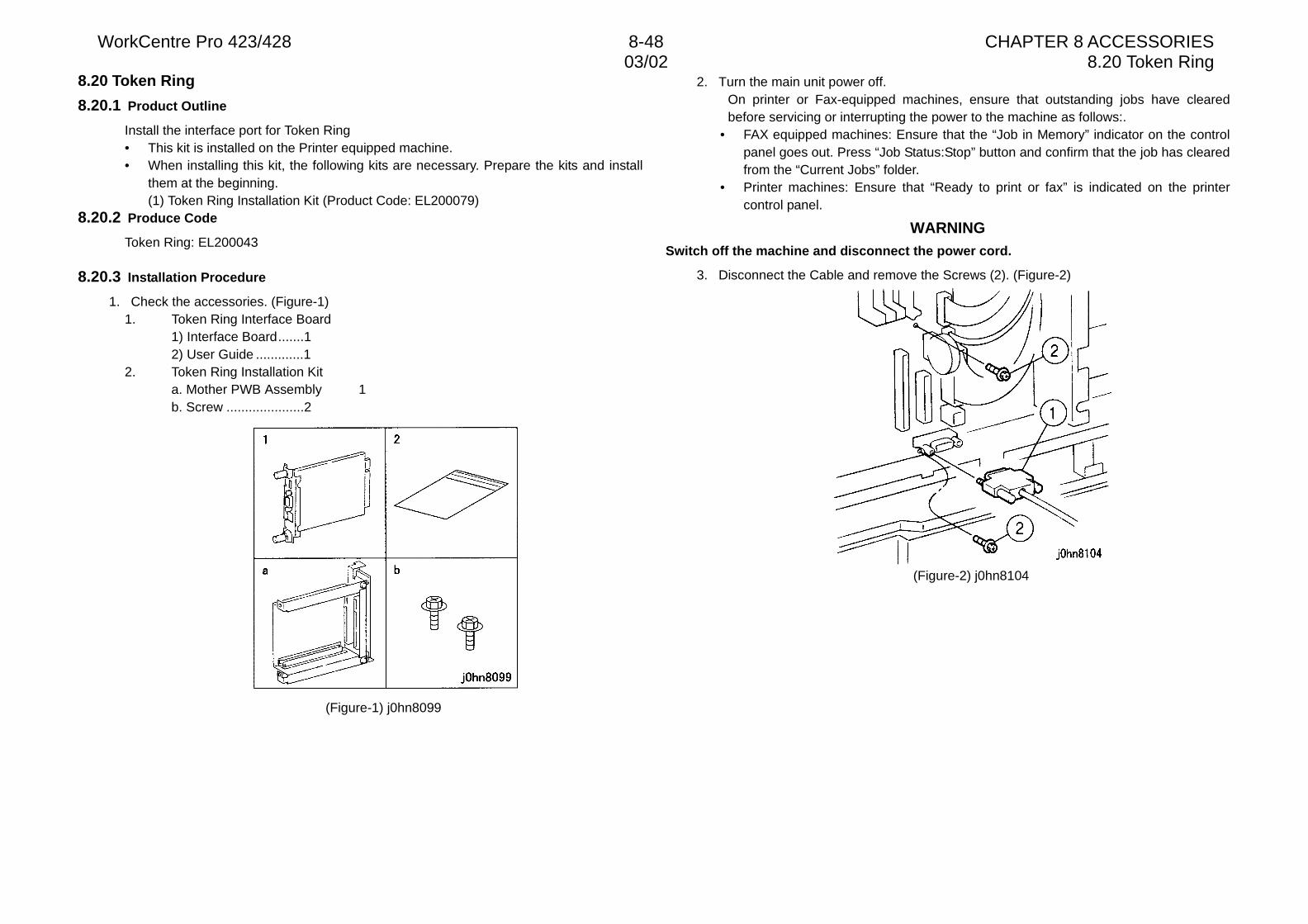
WorkCentre Pro 423/428 8-48 CHAPTER 8 ACCESSORIES03/02 8.20 Token Ring
8.20 Token Ring
8.20.1 Product Outline
Install the interface port for Token Ring• This kit is installed on the Printer equipped machine.• When installing this kit, the following kits are necessary. Prepare the kits and install
them at the beginning.(1) Token Ring Installation Kit (Product Code: EL200079)
8.20.2 Produce Code
Token Ring: EL200043
8.20.3 Installation Procedure
1. Check the accessories. (Figure-1)1. Token Ring Interface Board
1) Interface Board.......12) User Guide .............1
2. Token Ring Installation Kita. Mother PWB Assembly 1b. Screw .....................2
(Figure-1) j0hn8099
2. Turn the main unit power off.On printer or Fax-equipped machines, ensure that outstanding jobs have clearedbefore servicing or interrupting the power to the machine as follows:.
• FAX equipped machines: Ensure that the “Job in Memory” indicator on the controlpanel goes out. Press “Job Status:Stop” button and confirm that the job has clearedfrom the “Current Jobs” folder.
• Printer machines: Ensure that “Ready to print or fax” is indicated on the printercontrol panel.
WARNINGSwitch off the machine and disconnect the power cord.
3. Disconnect the Cable and remove the Screws (2). (Figure-2)
(Figure-2) j0hn8104
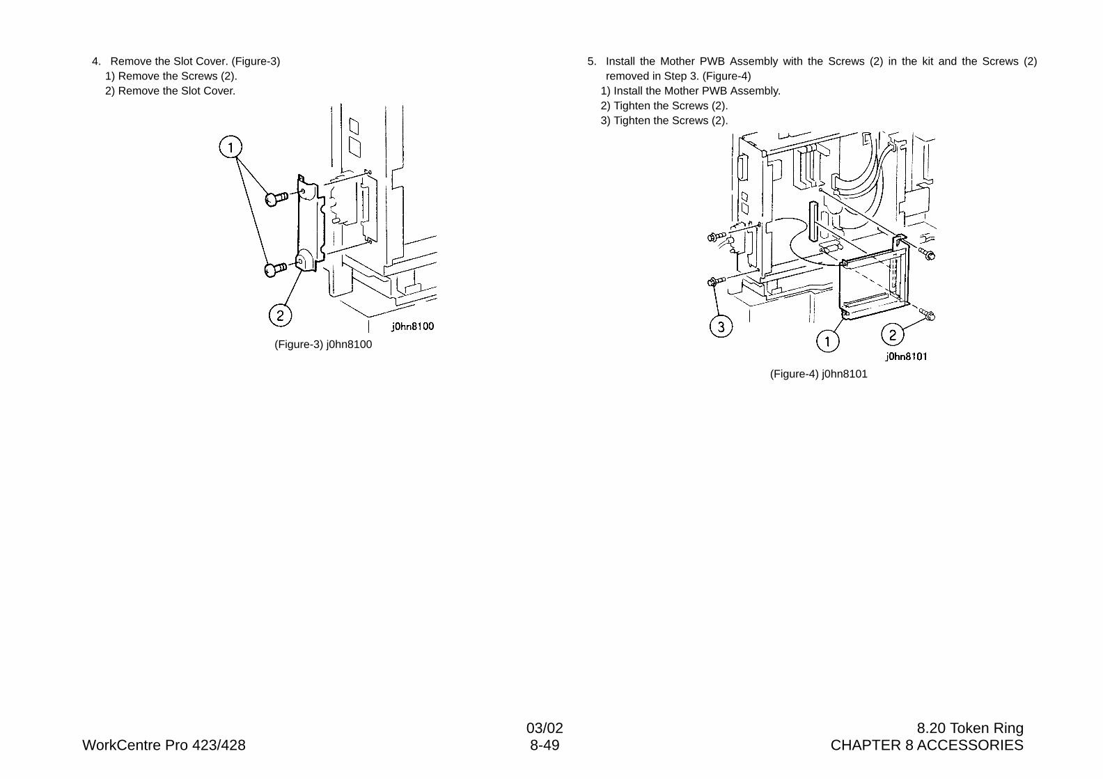
03/02 8.20 Token RingWorkCentre Pro 423/428 8-49 CHAPTER 8 ACCESSORIES
4. Remove the Slot Cover. (Figure-3)1) Remove the Screws (2).2) Remove the Slot Cover.
(Figure-3) j0hn8100
5. Install the Mother PWB Assembly with the Screws (2) in the kit and the Screws (2)removed in Step 3. (Figure-4)
1) Install the Mother PWB Assembly.2) Tighten the Screws (2).3) Tighten the Screws (2).
(Figure-4) j0hn8101
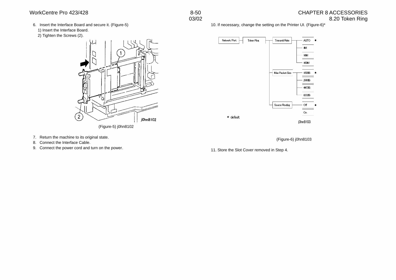
WorkCentre Pro 423/428 8-50 CHAPTER 8 ACCESSORIES03/02 8.20 Token Ring
6. Insert the Interface Board and secure it. (Figure-5)1) Insert the Interface Board.2) Tighten the Screws (2).
(Figure-5) j0hn8102
7. Return the machine to its original state.8. Connect the Interface Cable.9. Connect the power cord and turn on the power.
10. If necessary, change the setting on the Printer UI. (Figure-6)*
(Figure-6) j0hn8103
11. Store the Slot Cover removed in Step 4.
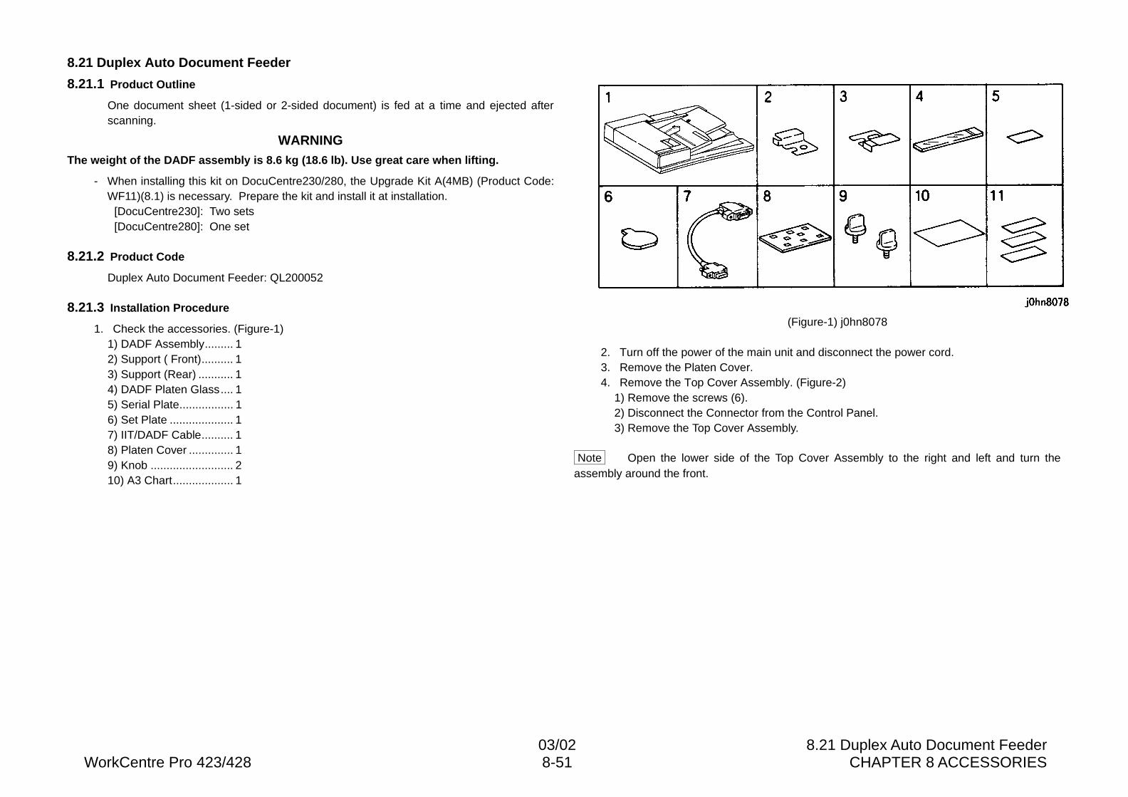
03/02 8.21 Duplex Auto Document FeederWorkCentre Pro 423/428 8-51 CHAPTER 8 ACCESSORIES
8.21 Duplex Auto Document Feeder
8.21.1 Product Outline
One document sheet (1-sided or 2-sided document) is fed at a time and ejected afterscanning.
WARNINGThe weight of the DADF assembly is 8.6 kg (18.6 lb). Use great care when lifting.
- When installing this kit on DocuCentre230/280, the Upgrade Kit A(4MB) (Product Code:WF11)(8.1) is necessary. Prepare the kit and install it at installation.
[DocuCentre230]: Two sets[DocuCentre280]: One set
8.21.2 Product Code
Duplex Auto Document Feeder: QL200052
8.21.3 Installation Procedure
1. Check the accessories. (Figure-1)1) DADF Assembly......... 12) Support ( Front).......... 13) Support (Rear) ........... 14) DADF Platen Glass.... 15) Serial Plate................. 16) Set Plate .................... 17) IIT/DADF Cable.......... 18) Platen Cover .............. 19) Knob .......................... 210) A3 Chart................... 1
(Figure-1) j0hn8078
2. Turn off the power of the main unit and disconnect the power cord.3. Remove the Platen Cover.4. Remove the Top Cover Assembly. (Figure-2)
1) Remove the screws (6).2) Disconnect the Connector from the Control Panel.3) Remove the Top Cover Assembly.
Note Open the lower side of the Top Cover Assembly to the right and left and turn theassembly around the front.
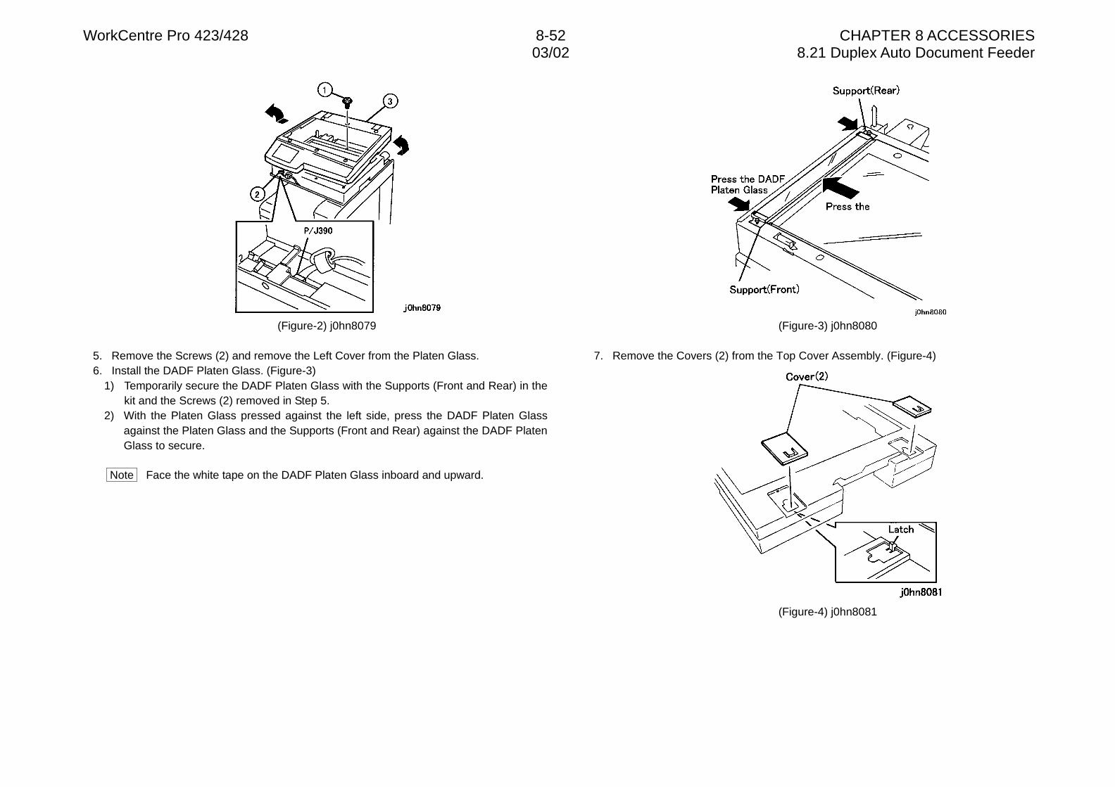
WorkCentre Pro 423/428 8-52 CHAPTER 8 ACCESSORIES03/02 8.21 Duplex Auto Document Feeder
(Figure-2) j0hn8079
5. Remove the Screws (2) and remove the Left Cover from the Platen Glass.6. Install the DADF Platen Glass. (Figure-3)
1) Temporarily secure the DADF Platen Glass with the Supports (Front and Rear) in thekit and the Screws (2) removed in Step 5.
2) With the Platen Glass pressed against the left side, press the DADF Platen Glassagainst the Platen Glass and the Supports (Front and Rear) against the DADF PlatenGlass to secure.
Note Face the white tape on the DADF Platen Glass inboard and upward.
(Figure-3) j0hn8080
7. Remove the Covers (2) from the Top Cover Assembly. (Figure-4)
(Figure-4) j0hn8081
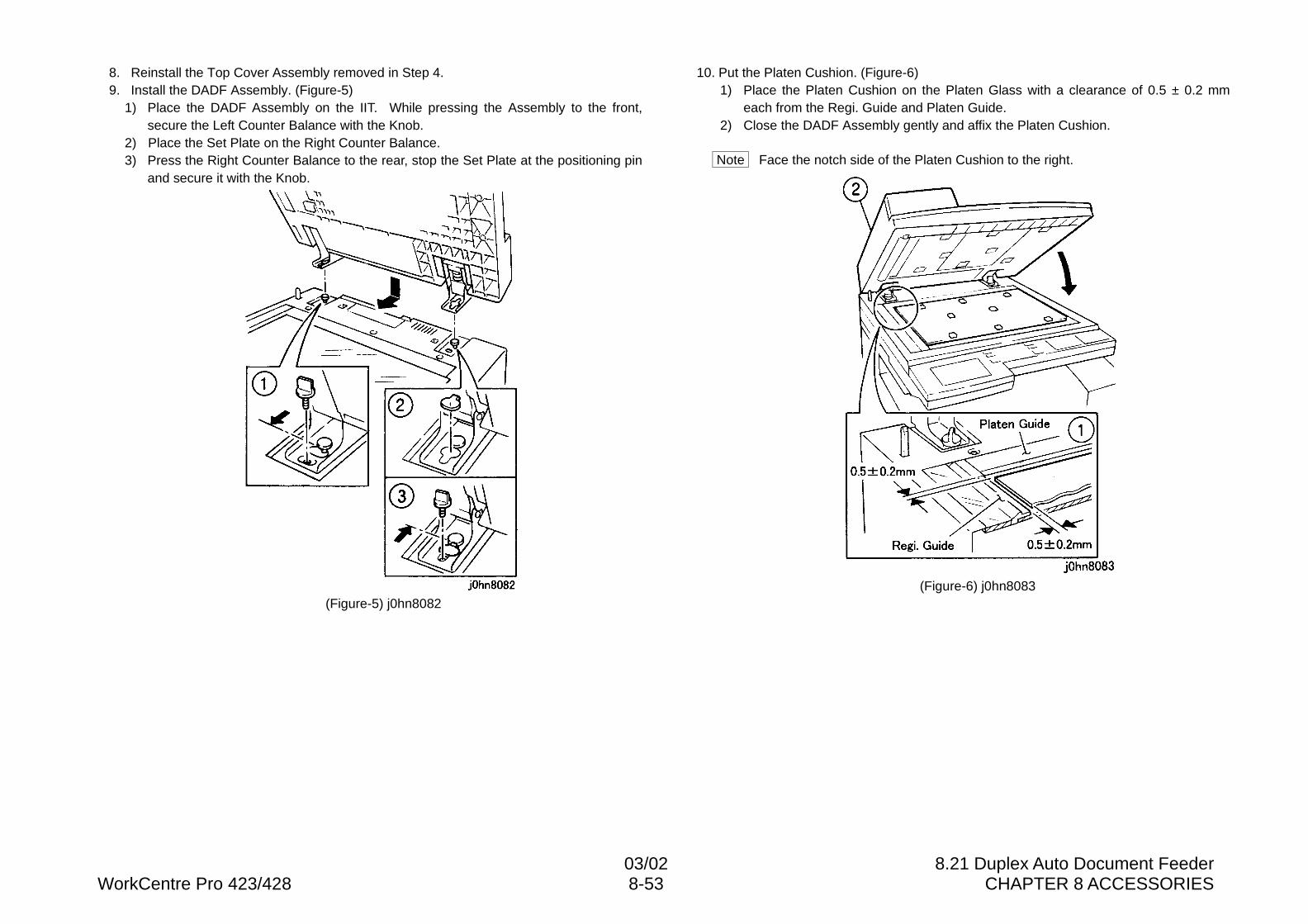
03/02 8.21 Duplex Auto Document FeederWorkCentre Pro 423/428 8-53 CHAPTER 8 ACCESSORIES
8. Reinstall the Top Cover Assembly removed in Step 4.9. Install the DADF Assembly. (Figure-5)
1) Place the DADF Assembly on the IIT. While pressing the Assembly to the front,secure the Left Counter Balance with the Knob.
2) Place the Set Plate on the Right Counter Balance.3) Press the Right Counter Balance to the rear, stop the Set Plate at the positioning pin
and secure it with the Knob.
(Figure-5) j0hn8082
10. Put the Platen Cushion. (Figure-6)1) Place the Platen Cushion on the Platen Glass with a clearance of 0.5 ± 0.2 mm
each from the Regi. Guide and Platen Guide.2) Close the DADF Assembly gently and affix the Platen Cushion.
Note Face the notch side of the Platen Cushion to the right.
(Figure-6) j0hn8083
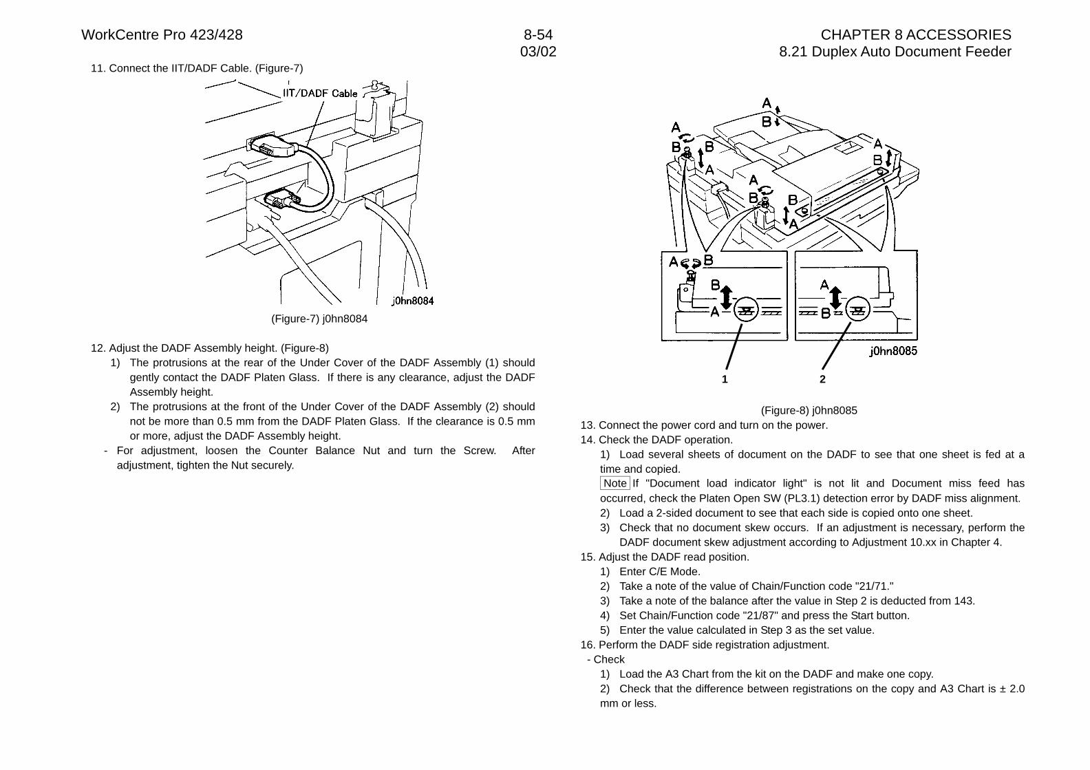
WorkCentre Pro 423/428 8-54 CHAPTER 8 ACCESSORIES03/02 8.21 Duplex Auto Document Feeder
11. Connect the IIT/DADF Cable. (Figure-7)
(Figure-7) j0hn8084
12. Adjust the DADF Assembly height. (Figure-8)1) The protrusions at the rear of the Under Cover of the DADF Assembly (1) should
gently contact the DADF Platen Glass. If there is any clearance, adjust the DADFAssembly height.
2) The protrusions at the front of the Under Cover of the DADF Assembly (2) shouldnot be more than 0.5 mm from the DADF Platen Glass. If the clearance is 0.5 mmor more, adjust the DADF Assembly height.
- For adjustment, loosen the Counter Balance Nut and turn the Screw. Afteradjustment, tighten the Nut securely.
(Figure-8) j0hn808513. Connect the power cord and turn on the power.14. Check the DADF operation.
1) Load several sheets of document on the DADF to see that one sheet is fed at atime and copied. Note If "Document load indicator light" is not lit and Document miss feed hasoccurred, check the Platen Open SW (PL3.1) detection error by DADF miss alignment.2) Load a 2-sided document to see that each side is copied onto one sheet.3) Check that no document skew occurs. If an adjustment is necessary, perform the
DADF document skew adjustment according to Adjustment 10.xx in Chapter 4.15. Adjust the DADF read position.
1) Enter C/E Mode.2) Take a note of the value of Chain/Function code "21/71."3) Take a note of the balance after the value in Step 2 is deducted from 143.4) Set Chain/Function code "21/87" and press the Start button.5) Enter the value calculated in Step 3 as the set value.
16. Perform the DADF side registration adjustment.- Check
1) Load the A3 Chart from the kit on the DADF and make one copy.2) Check that the difference between registrations on the copy and A3 Chart is ± 2.0mm or less.
1 2
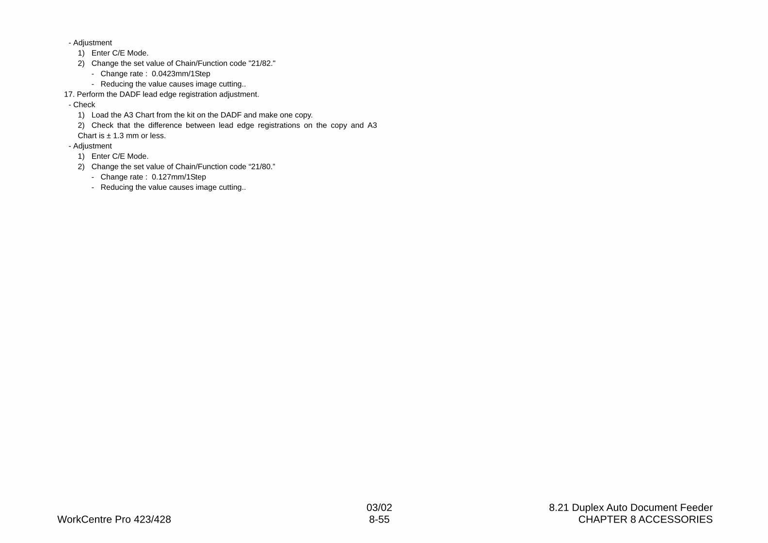
03/02 8.21 Duplex Auto Document FeederWorkCentre Pro 423/428 8-55 CHAPTER 8 ACCESSORIES
- Adjustment1) Enter C/E Mode.2) Change the set value of Chain/Function code "21/82."
- Change rate : 0.0423mm/1Step- Reducing the value causes image cutting..
17. Perform the DADF lead edge registration adjustment.- Check
1) Load the A3 Chart from the kit on the DADF and make one copy.2) Check that the difference between lead edge registrations on the copy and A3Chart is ± 1.3 mm or less.
- Adjustment1) Enter C/E Mode.2) Change the set value of Chain/Function code “21/80.”
- Change rate : 0.127mm/1Step- Reducing the value causes image cutting..
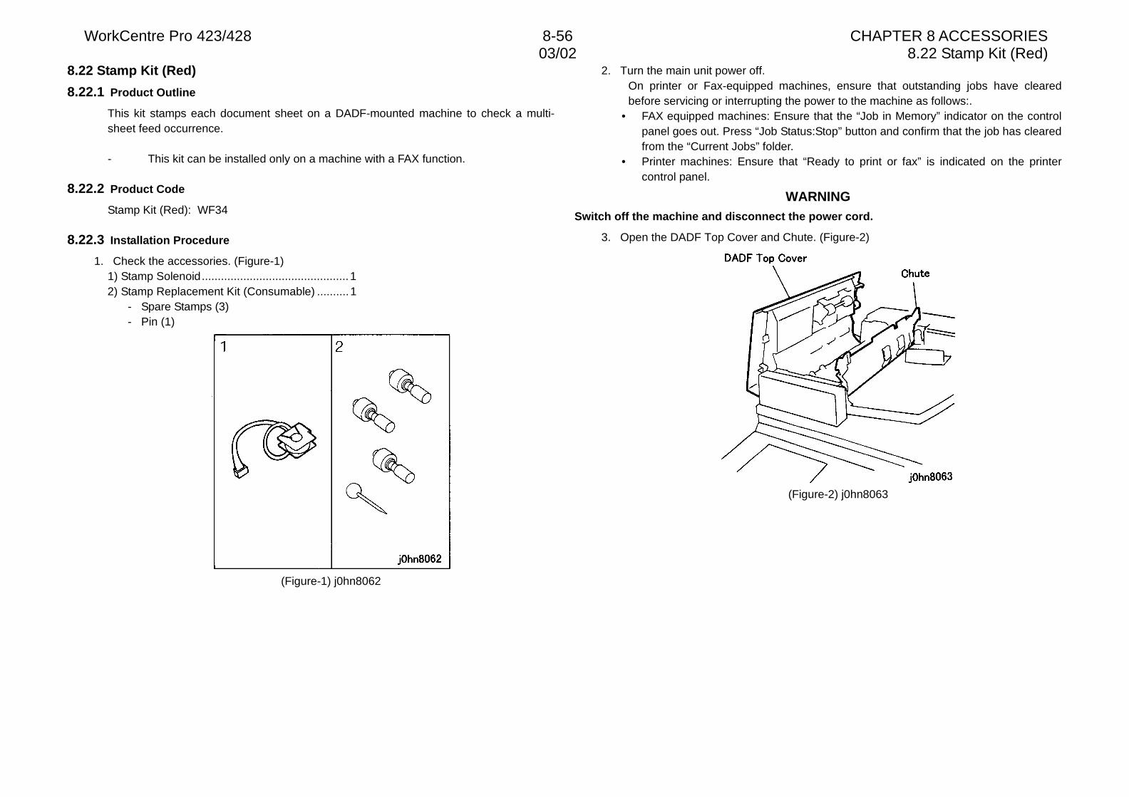
WorkCentre Pro 423/428 8-56 CHAPTER 8 ACCESSORIES03/02 8.22 Stamp Kit (Red)
8.22 Stamp Kit (Red)
8.22.1 Product Outline
This kit stamps each document sheet on a DADF-mounted machine to check a multi-sheet feed occurrence.
- This kit can be installed only on a machine with a FAX function.
8.22.2 Product Code
Stamp Kit (Red): WF34
8.22.3 Installation Procedure
1. Check the accessories. (Figure-1)1) Stamp Solenoid..............................................12) Stamp Replacement Kit (Consumable) ..........1
- Spare Stamps (3)- Pin (1)
(Figure-1) j0hn8062
2. Turn the main unit power off.On printer or Fax-equipped machines, ensure that outstanding jobs have clearedbefore servicing or interrupting the power to the machine as follows:.
• FAX equipped machines: Ensure that the “Job in Memory” indicator on the controlpanel goes out. Press “Job Status:Stop” button and confirm that the job has clearedfrom the “Current Jobs” folder.
• Printer machines: Ensure that “Ready to print or fax” is indicated on the printercontrol panel.
WARNINGSwitch off the machine and disconnect the power cord.
3. Open the DADF Top Cover and Chute. (Figure-2)
(Figure-2) j0hn8063
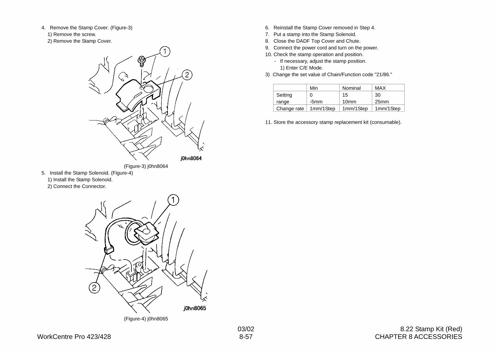
03/02 8.22 Stamp Kit (Red)WorkCentre Pro 423/428 8-57 CHAPTER 8 ACCESSORIES
4. Remove the Stamp Cover. (Figure-3)1) Remove the screw.2) Remove the Stamp Cover.
(Figure-3) j0hn80645. Install the Stamp Solenoid. (Figure-4)
1) Install the Stamp Solenoid.2) Connect the Connector.
(Figure-4) j0hn8065
6. Reinstall the Stamp Cover removed in Step 4.7. Put a stamp into the Stamp Solenoid.8. Close the DADF Top Cover and Chute.9. Connect the power cord and turn on the power.10. Check the stamp operation and position.
- If necessary, adjust the stamp position.1) Enter C/E Mode.
3) Change the set value of Chain/Function code "21/86."
Min Nominal MAXSettingrange
0-5mm
1510mm
3025mm
Change rate 1mm/1Step 1mm/1Step 1mm/1Step
11. Store the accessory stamp replacement kit (consumable).

WorkCentre Pro 423/428 8-58 CHAPTER 8 ACCESSORIES03/02 8.22 Stamp Kit (Red)

CHAPTER 9 BSD (Block Schematic Diagram)

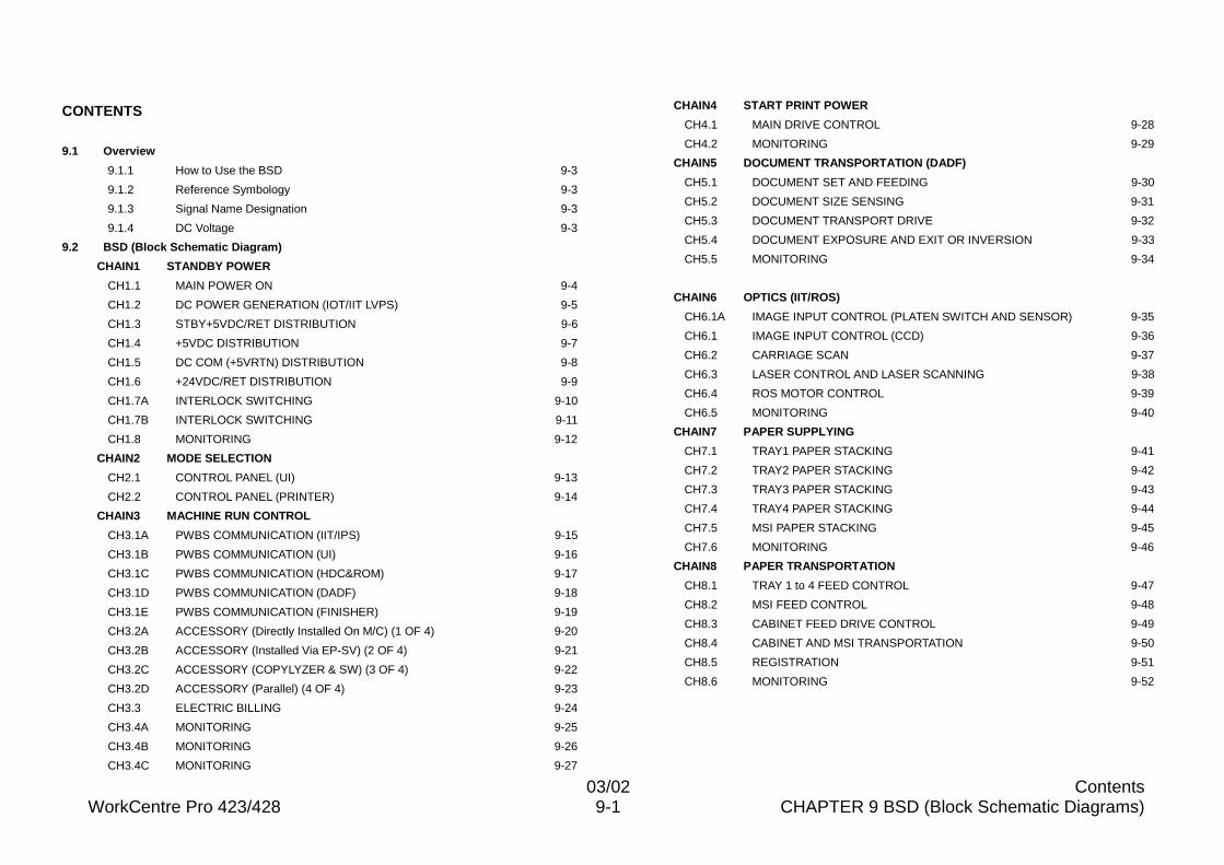
03/02 ContentsWorkCentre Pro 423/428 9-1 CHAPTER 9 BSD (Block Schematic Diagrams)
CONTENTS
9.1 Overview
9.1.1 How to Use the BSD 9-3
9.1.2 Reference Symbology 9-3
9.1.3 Signal Name Designation 9-3
9.1.4 DC Voltage 9-3
9.2 BSD (Block Schematic Diagram)
CHAIN1 STANDBY POWER
CH1.1 MAIN POWER ON 9-4
CH1.2 DC POWER GENERATION (IOT/IIT LVPS) 9-5
CH1.3 STBY+5VDC/RET DISTRIBUTION 9-6
CH1.4 +5VDC DISTRIBUTION 9-7
CH1.5 DC COM (+5VRTN) DISTRIBUTION 9-8
CH1.6 +24VDC/RET DISTRIBUTION 9-9
CH1.7A INTERLOCK SWITCHING 9-10
CH1.7B INTERLOCK SWITCHING 9-11
CH1.8 MONITORING 9-12
CHAIN2 MODE SELECTION
CH2.1 CONTROL PANEL (UI) 9-13
CH2.2 CONTROL PANEL (PRINTER) 9-14
CHAIN3 MACHINE RUN CONTROL
CH3.1A PWBS COMMUNICATION (IIT/IPS) 9-15
CH3.1B PWBS COMMUNICATION (UI) 9-16
CH3.1C PWBS COMMUNICATION (HDC&ROM) 9-17
CH3.1D PWBS COMMUNICATION (DADF) 9-18
CH3.1E PWBS COMMUNICATION (FINISHER) 9-19
CH3.2A ACCESSORY (Directly Installed On M/C) (1 OF 4) 9-20
CH3.2B ACCESSORY (Installed Via EP-SV) (2 OF 4) 9-21
CH3.2C ACCESSORY (COPYLYZER & SW) (3 OF 4) 9-22
CH3.2D ACCESSORY (Parallel) (4 OF 4) 9-23
CH3.3 ELECTRIC BILLING 9-24
CH3.4A MONITORING 9-25
CH3.4B MONITORING 9-26
CH3.4C MONITORING 9-27
CHAIN4 START PRINT POWER
CH4.1 MAIN DRIVE CONTROL 9-28
CH4.2 MONITORING 9-29
CHAIN5 DOCUMENT TRANSPORTATION (DADF)
CH5.1 DOCUMENT SET AND FEEDING 9-30
CH5.2 DOCUMENT SIZE SENSING 9-31
CH5.3 DOCUMENT TRANSPORT DRIVE 9-32
CH5.4 DOCUMENT EXPOSURE AND EXIT OR INVERSION 9-33
CH5.5 MONITORING 9-34
CHAIN6 OPTICS (IIT/ROS)
CH6.1A IMAGE INPUT CONTROL (PLATEN SWITCH AND SENSOR) 9-35
CH6.1 IMAGE INPUT CONTROL (CCD) 9-36
CH6.2 CARRIAGE SCAN 9-37
CH6.3 LASER CONTROL AND LASER SCANNING 9-38
CH6.4 ROS MOTOR CONTROL 9-39
CH6.5 MONITORING 9-40
CHAIN7 PAPER SUPPLYING
CH7.1 TRAY1 PAPER STACKING 9-41
CH7.2 TRAY2 PAPER STACKING 9-42
CH7.3 TRAY3 PAPER STACKING 9-43
CH7.4 TRAY4 PAPER STACKING 9-44
CH7.5 MSI PAPER STACKING 9-45
CH7.6 MONITORING 9-46
CHAIN8 PAPER TRANSPORTATION
CH8.1 TRAY 1 to 4 FEED CONTROL 9-47
CH8.2 MSI FEED CONTROL 9-48
CH8.3 CABINET FEED DRIVE CONTROL 9-49
CH8.4 CABINET AND MSI TRANSPORTATION 9-50
CH8.5 REGISTRATION 9-51
CH8.6 MONITORING 9-52
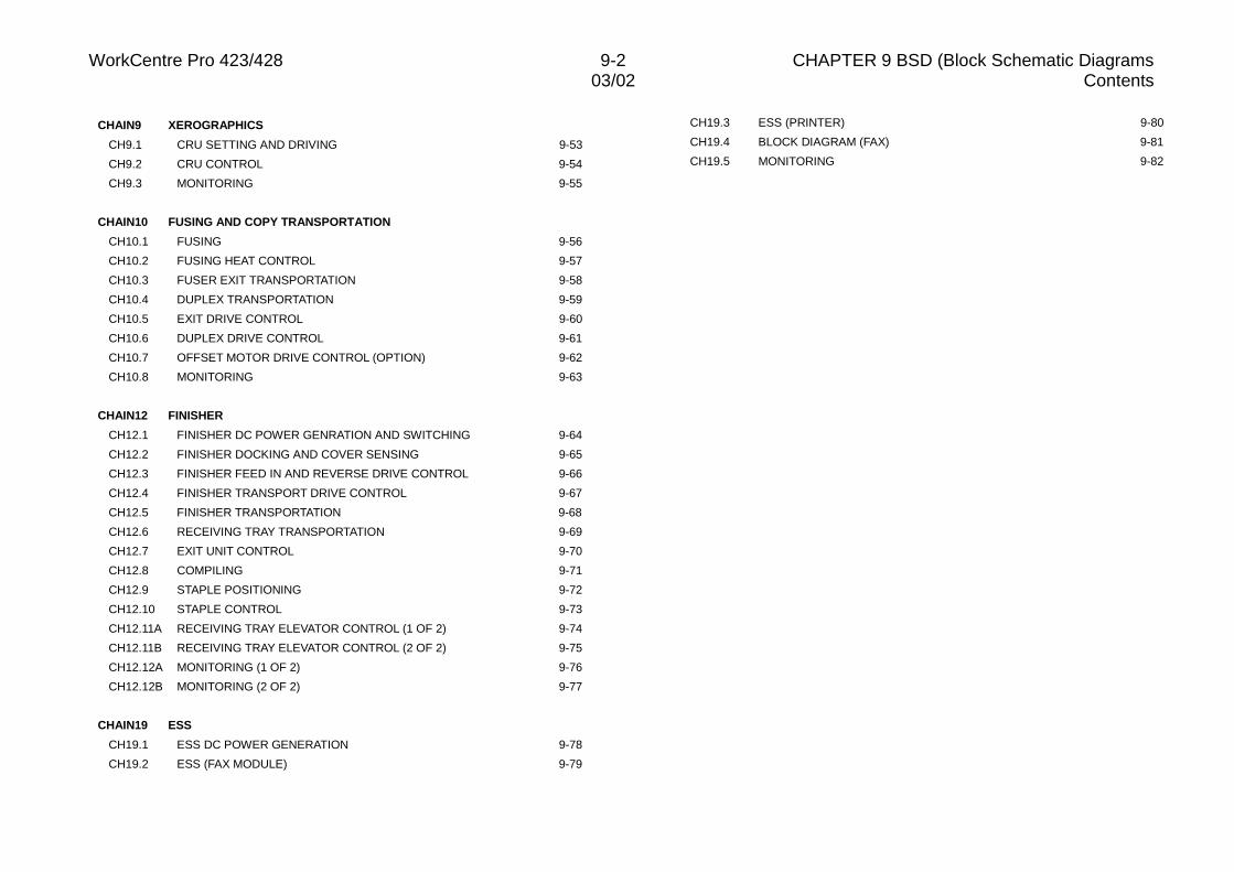
WorkCentre Pro 423/428 9-2 CHAPTER 9 BSD (Block Schematic Diagrams03/02 Contents
CHAIN9 XEROGRAPHICS
CH9.1 CRU SETTING AND DRIVING 9-53
CH9.2 CRU CONTROL 9-54
CH9.3 MONITORING 9-55
CHAIN10 FUSING AND COPY TRANSPORTATION
CH10.1 FUSING 9-56
CH10.2 FUSING HEAT CONTROL 9-57
CH10.3 FUSER EXIT TRANSPORTATION 9-58
CH10.4 DUPLEX TRANSPORTATION 9-59
CH10.5 EXIT DRIVE CONTROL 9-60
CH10.6 DUPLEX DRIVE CONTROL 9-61
CH10.7 OFFSET MOTOR DRIVE CONTROL (OPTION) 9-62
CH10.8 MONITORING 9-63
CHAIN12 FINISHER
CH12.1 FINISHER DC POWER GENRATION AND SWITCHING 9-64
CH12.2 FINISHER DOCKING AND COVER SENSING 9-65
CH12.3 FINISHER FEED IN AND REVERSE DRIVE CONTROL 9-66
CH12.4 FINISHER TRANSPORT DRIVE CONTROL 9-67
CH12.5 FINISHER TRANSPORTATION 9-68
CH12.6 RECEIVING TRAY TRANSPORTATION 9-69
CH12.7 EXIT UNIT CONTROL 9-70
CH12.8 COMPILING 9-71
CH12.9 STAPLE POSITIONING 9-72
CH12.10 STAPLE CONTROL 9-73
CH12.11A RECEIVING TRAY ELEVATOR CONTROL (1 OF 2) 9-74
CH12.11B RECEIVING TRAY ELEVATOR CONTROL (2 OF 2) 9-75
CH12.12A MONITORING (1 OF 2) 9-76
CH12.12B MONITORING (2 OF 2) 9-77
CHAIN19 ESS
CH19.1 ESS DC POWER GENERATION 9-78
CH19.2 ESS (FAX MODULE) 9-79
CH19.3 ESS (PRINTER) 9-80
CH19.4 BLOCK DIAGRAM (FAX) 9-81
CH19.5 MONITORING 9-82
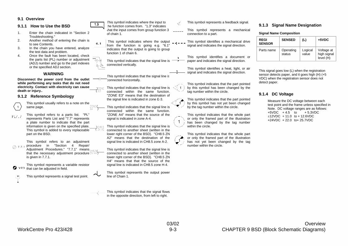
03/02 OverviewWorkCentre Pro 423/428 9-3 CHAPTER 9 BSD (Block Schematic Diagrams)
9.1 Overview
9.1.1 How to Use the BSD
1. Enter the chain indicated in "Section 2Troubleshooting."
2. Another method of entering the chain isto see Contents.
3. In the chain you have entered, analyzethe test data and problem.
4. Once the fault has been located, checkthe parts list (PL) number or adjustment(ADJ) number and go to the part indexesor the specified ADJ section.
WARNINGDisconnect the power cord from the outletwhile performing any tasks that do not needelectricity. Contact with electricity can causedeath or injury..
9.1.2 Reference Symbology
This symbol usually refers to a note on thesame page.
This symbol refers to a parts list. "PL"represents Parts List and "7.7" representsa plate number to indicate that the partinformation is given on the specified plate.This symbol is added to every replaceablepart on the BSD.
This symbol refers to an adjustmentprocedure in "Section 4 Repair/Adjustment Procedures." "7.7.1" meansthat the necessary adjustment procedureis given in 7.7.1.
This symbol represents a variable resistorthat can be adjusted in field.
This symbol represents a signal test point.
This symbol indicates where the input tothe function comes from. "1.3" indicatesthat the input comes from group function 3of chain 1.
This symbol indicates where the outputfrom the function is going e.g. "6.1"indicates that the output is going to groupfunction 1 of chain 6.
This symbol indicates that the signal line isconnected vertically.
This symbol indicates that the signal line isconnected horizontally.
This symbol indicates that the signal line isconnected within the same function."ZONE E3" means that the destination ofthe signal line is indicated in zone E-3.
This symbol indicates that the signal line isconnected within the same function."ZONE A4" means that the source of thesignal is indicated in zone A-4.
This symbol indicates that the signal line isconnected to another sheet (written in thelower right corner of the BSD). "CH8.5 ZNA2" means that the destination of thesignal line is indicated in CH8.5 zone A-2.
This symbol indicates that the signal line isconnected to another sheet (written in thelower right corner of the BSD). "CH8.5 ZNH4" means that that the source of thesignal line is indicated in CH8.5 zone H-4.
This symbol represents the output powerline of Chain 1.
This symbol indicates that the signal flowsin the opposite direction, from left to right.
This symbol represents a feedback signal.
This symbol represents a mechanicalconnection to a part.
This symbol identifies a mechanical drivesignal and indicates the signal direction.
This symbol identifies a document orpaper and indicates the signal direction.
This symbol identifies a heat, light, or airsignal and indicates the signal direction.
This symbol indicates that the part pointedby this symbol has been changed by thetag number within the circle.
This symbol indicates that the part pointedby this symbol has not yet been changedby the tag number within the circle.
This symbol indicates that the whole partor only the framed part of the illustrationhas been changed by the tag numberwithin the circle.
This symbol indicates that the whole partor only the framed part of the illustrationhas not yet been changed by the tagnumber within the circle.
9.1.3 Signal Name Designation
Signal Name Composition
REGISENSOR
SENSED (L) +5VDC
Parts name Operatingstatus
Logicalvalue
Voltage athigh signallevel (H)
This signal goes low (L) when the registrationsensor detects paper, and it goes high (H) (+5VDC) when the registration sensor does notdetect paper.
9.1.4 DC Voltage
Measure the DC voltage between eachtest point and the frame unless specified inNote. DC voltage ranges are as follows:+5VDC + 4.5 to + 5.3VDC±12VDC + 11.0 to + 12.6VDC+24VDC + 22.0 to+ 25.7VDC
3/���
1