workbench no. 265 - may/june 2001
TRANSCRIPT

Woodworking To Improve Your Home
TM
ENTER TO WIN! Ultimate Deck-Building Contest
Modular Design Makes It Easy
Gazebogarden
www.WorkbenchMagazine.com No 265 May/June 2001
Gazebo
Plus:● 5 Surefire
Storage Solutions
● Build a CherryBedside Table
Modular Design Makes It Easy
garden
ENTER TO WIN! Ultimate Deck-Building Contest
Plus:● 5 Surefire
Storage Solutions
● Build a CherryBedside Table
Contents
2 W O R K B E N C H ■■ M A Y | J U N E 2 0 0 1
18
22 30
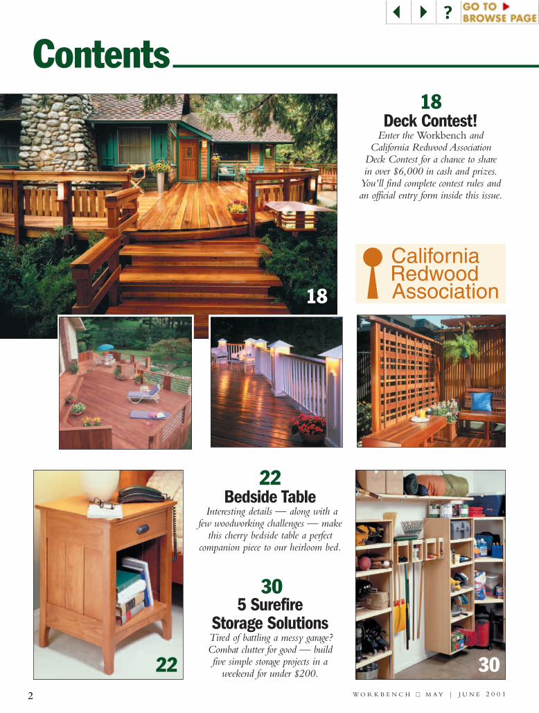
22Bedside Table
Interesting details — along with afew woodworking challenges — make
this cherry bedside table a perfectcompanion piece to our heirloom bed.
305 Surefire
Storage SolutionsTired of battling a messy garage? Combat clutter for good — build five simple storage projects in a
weekend for under $200.
18Deck Contest!
Enter the Workbench and California Redwood Association
Deck Contest for a chance to share in over $6,000 in cash and prizes.
You’ll find complete contest rules andan official entry form inside this issue.
CaliforniaRedwoodAssociation

14In The Shop55Around The House59Sources & Resources60Craftsmanship
5Questions & Answers
8Tips & Techniques
11Workbench Interactive.com
3W O R K B E N C H ■■ M A Y | J U N E 2 0 0 1
TM
DEPARTMENTS
608
36Garden Gazebo
Thanks to a modular design and aunique layout frame, this fancy gazebo
is truly a builder-friendly project.Even the matching louvered cupola
is easy to make when you follow our practical tips and step-by-step photos.
36
President/Publisher:Donald B. Peschke •
Corporate Services: Corporate Vice Presidents: Douglas L. Hicks,Mary R. Scheve • Controller: Robin Hutchinson • Senior Accountant:Laura Thomas • Accounts Payable: Mary Schultz • AccountsReceivable: Margo Petrus • Production Director: George Chmielarz •Network Administrator: Cris Schwanebeck • New Media Manager:Gordon Gaippe • Web Site Art Director: Gene Pedersen • E-Commerce Analyst: Carol Pelz-Schoeppler • Web Site ContentManager: David Briggs • Professional Development Dir.: Michal Sigel• Human Resources Asst.: Kirsten Koele • Office Manager: Noelle M.Carroll • Facilities Manager: Julia Fish • Receptionist: Jeanne Johnson• Mail/Delivery Clerk: Lou Webber • Circulation: SubscriberServices Director: Sandy Baum • Circulation Manager - NewBusiness: Wayde Klingbeil • Multi-Media Promotions Manager:Rick Junkins • Renewal Manager: Paige Rogers • Billing &Collections Manager: Rebecca Cunningham • Marketing Analyst:Kris Schlemmer • Assoc. Marketing Analyst: Paula M. DeMatteis •Promotions Analyst: Patrick A. Walsh • Creative Resources:Associate Editor: Craig Ruegsegger • Assistant Editor: Joe Irwin • ArtDirector: Douglas A. Flint • Senior Graphic Designers: ChrisGlowacki, Mark Hayes, Robin Dowdell • Graphic Designers: VuNguyen • Products Group: Operations Director: Bob Baker •Customer Service Manager: Jennie Enos • Warehouse Supervisor:Nancy Johnson • Buyer: Linda Jones • Administrative Assistant:Nancy Downey • Technical Service Representative: John Audette •Customer Service Representatives: Anna Cox, Tammy Truckenbrod,Deborah Rich, April Revell, Valerie Jo Riley, Linda Stepp, Tamara L.Hidlebaugh • Warehouse Staff: Sylvia Carey, Sheryl Knox,Albert Voigt• Fulfillment: Dustin Hess, Micheal Overbey • Woodsmith Store:Manager: Dave Larson • Assistant Manager: Tim Thelen • SalesStaff:Wendell Stone, Jim Barnett, Kathy Smith, Larry Morrison, HaroldCashman, Mark Johnson • Office Mgr.:Vicki Edwards
VOLUME 57 NUMBER 3EDITOR Tim Robertson
ASSISTANT EDITORS Bill LinkKevin Shoesmith
Joel HessMike Donovan
ART DIRECTOR Robert L. FossSR. ILLUSTRATOR Susan R. Jessen
ILLUSTRATOR Mark S. GravesCONTRIBUTING ILLUSTRATOR Erich Lage
CONTRIBUTING EDITOR Kerry Gibson
CREATIVE DIRECTOR Ted KralicekSENIOR PHOTOGRAPHER Crayola England
PROJECT COORDINATOR Kent WelshPROJECT DEVELOPER Ken Munkel
PROJECT DESIGNERS Chris Fitch & Craig IsekeSHOP CRAFTSMEN Steve Curtis & Steve Johnson
ELEC. PUB. DIRECTOR Douglas M. LidsterPRE-PRESS IMAGE SPECS. Troy Clark
Minniette Johnson
PRESIDENT & PUBLISHER Donald B. Peschke
ADVERTISING SALES MANAGERSMary K. Day (515) 282-7000 ext. 2200
George A. Clark (515) 282-7000 ext. 2201DIRECT RESPONSE ADVERTISING
SALES MANAGERLisa Wagner (407) 645-5165
The Ad Rep FirmPUBLISHING CONSULTANT
Peter H. Miller (202) 362-9367
4 W O R K B E N C H ■■ M A Y | J U N E 2 0 0 1
E D I T O R ’ S N O T E S
How do you divide a pie intoeight equal pieces? Not ahomemade pie with a killer
crust and fancy filling. I’m talkingabout laying out eight identical, pie-shaped sections of a circle.
Okay I know. It’s just basic geom-etry, right? Nothing difficult about it, atleast on paper. But it did present a bitof a challenge when building theGarden Gazebo for this issue. That’sbecause the gazebo has eight symmet-rical sides — a perfect octagon.
This meant that the eight footingsfor the gazebo had to be precisely thesame disance apart.That’s a real trick,especially when working outside onuneven ground. I think you’ll like thesolution we came up with — a rigid,eight-sided, wood frame that lookslike a giant spider web. It provided afoolproof way for locating the footings.
That’s just one of the things thatmakes this gazebo such an interestingproject. Even if you don’t plan to buildit, be sure to check out our construc-tion tips. I’m sure there are a few prac-
tical ideas you can use on your nextproject. For example, there’s a tablesaw jig for ripping the thin, louveredstrips on the gazebo’s cupola (shownabove).And a nifty method for gluingup the wedge-shaped roof pieces isdefinitely worth a closer look.
NEW FACESWe’re pleased that Mike Donovan hasjoined us as an Assistant Editor.Mike isa young guy in the process of remod-eling an old (1880’s) house. With hisexperience in home improvementand furniture building, he’s a greataddition to the Workbench team.
As for me? Let’s just say I’ve beenbuilding home improvement projectssince Mike was a kid. My most recent“project” is to pick up the responsibil-ities as Editor at Workbench. I’m excit-ed about all the great projects we havein store for you. If you’d like to shareyour own project ideas,drop me a line.I look forward to hearing from you.
WORKBENCH (ISSN 0043-8057) is published bimonthly(Jan., Mar., May, July, Sept., Nov.) by August Home Publishing
Company, 2200 Grand Ave., Des Moines, IA 50312.Workbench is a trademark of August Home Publishing.
Copyright©2001 August Home Publishing Company.All rights reserved.
Subscription rates: Single copy, $3.95. One-year subscription(6 issues), $15.94; two-year sub., $27.95; three-year sub., $39.95.Canadian/Intl., add $10.00 per year. Periodicals postage paid at
Des Moines, Iowa, and at additional offices.“USPS/Perry-Judd’s Heartland Division automatable poly.”
Postmaster: Send address changes to Workbench,PO Box 37272, Boone, IA 50037-0272.
Printed in U.S.A.
TM
HOW TO REACH US
On The Internet:www.WorkbenchMagazine.com
Free WeeklyWoodworking Tip:www.WoodworkingTips.com
Editorial Questions:Workbench Magazine2200 Grand Ave.Des Moines, IA 50312e-mail: [email protected]
Subscriber Services:Workbench Customer ServiceP.O. Box 842 Des Moines, IA 50304-9961 Phone: (800) 311-3991Fax: (515) 283-0447
Online: www.WorkbenchMagazine.com• Access your account• Check on or make a subscription payment• Change your mailing or e-mail address• Tell us if you’ve missed an issue• Renew your subscription
5 W O R K B E N C H ■■ M A Y | J U N E 2 0 0 1
Questions & Answers
QWhen workingwith crown mold-ing, I’ve never
had much success gettinga tight-fitting joint oninside corners.What’s thebest way to do this?
Terry UnderwoodColorado Springs, CO
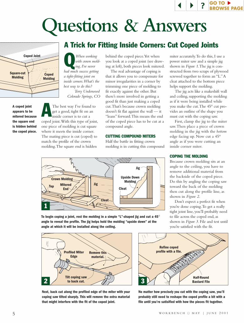
AThe best way I’ve found toget a good, tight fit on aninside corner is to cut a
coped joint.With this type of joint,one piece of molding is cut squarewhere it meets the inside corner.The mating piece is cut (coped) tomatch the profile of the crownmolding.The square end is hidden
behind the coped piece.Yet whenyou look at a coped joint (see draw-ing at left), both pieces look mitered.
The real advantage of coping isthat it allows you to compensate forminor irregularities in a corner bytrimming one piece of molding tofit exactly against the other. Butthere’s more involved in getting agood fit than just making a copedcut.That’s because crown moldingdoesn’t fit flat against the wall — it“leans” forward.This means the endof the coped piece has to be cut at acompound angle.
CUTTING COMPOUND MITERSHalf the battle in fitting crownmolding is in cutting this compound
miter accurately.To do this, I use apower miter saw and a simple jigshown in Figure 1.The jig is con-structed from two scraps of plywoodscrewed together to form an “L.”Acleat attached to the bottom piecehelps support the molding.
The jig acts like a makeshift walland ceiling, supporting the moldingas if it were being installed whileyou make the cut.The 45° cut pro-vides an outline of the shape youmust cut with the coping saw.
First, clamp the jig to the mitersaw.Then place a piece of crownmolding in the jig with the bottomedge facing up. Now cut a 45°angle as if you were cutting aninside corner miter.
COPING THE MOLDINGBecause crown molding sits at anangle to the ceiling, you have toremove additional material fromthe backside of the coped piece.Do this by angling the coping sawtoward the back of the moldingthen cut along the profile line, asshown in Figure 2.
Don’t expect a perfect fit whenyou’re done coping.To get a reallytight joint line, you’ll probably needto file across the coped end, asshown in Figure 3. File and test untilyou’re satisfied with the fit.
A Trick for Fitting Inside Corners: Cut Coped Joints
Profiled MiterEdge
Tilt coping sawto back cut.
Remove thismaterial.
Half-RoundBastard File
Refine copedprofile with a file.
Crown MoldingJig
Cleat
MiteredEnd
Top
To begin coping a joint, rest the molding in a simple “L”-shaped jig and cut a 45°angle to reveal the profile. The jig helps hold the molding “upside down” at theangle at which it will be installed along the ceiling.
No matter how precisely you cut with the coping saw, you’llprobably still need to reshape the coped profile a bit with afile until you’re satisified with how the pieces fit together.
Square-cutMolding
Coped Joint
CopedMolding
Next, back cut along the profiled edge of the miter with yourcoping saw tilted sharply. This will remove the extra materialthat might interfere with the fit of the coped joint.
A coped jointappears to bemitered becausethe square endis hidden behindthe coped piece.
Cleat
Jig
Upside DownMolding
1
2 3

QI’ve always admired the detailedmolding often found on finepieces of furniture. Is there a
simple way I can make these elegantmoldings myself?
Jeff HolderhouseSalt Lake City, UT
AAll you need to make profes-sional looking moldings is arouter and a few ordinary
bits.The idea is to rout a profile intwo (or more) strips of wood andthen glue them together to create a“built-up” molding as shown at left.
If you look at the drawingsbelow, you can see that all of theseprofiles are made using four com-mon router bits: a cove bit, a Romanogee bit, and two roundover bits.There are two basic ways to createthese moldings, but the technique issimilar for both.
STRIP MOLDINGStrip molding is what I like toapply to the top of cabinets.Tomake strip molding, all you have todo is rout a profile on the frontedge of several strips of wood andrip them to desired width.
After gluing up the strips tocreate the profile you’re after, miterthe molding to fit.Then attach thebuilt-up molding to the top of thecabinet as shown in Figure 1.
LAYERED MOLDINGAnother typical way to use built-upmoldings is to rout the profiles onthe edges and ends of full-widthboards.Then glue up the stack ofboards in layers as shown in Figure 2.
One reason I like layered mold-ing is because it’s faster to makeand easier to install than stripmolding.That’s because you don’thave to mess around with miteringthe corners. Here’s a tip: If you’rehaving problems with the piecessliding around during glue up, nail afew wire brads in one of the layers.Then snip off the heads of the brads.
Layered molding does have adisadvantage, though. Becauseyou’re routing the ends, the endgrain is exposed. I usually getaround this problem by sanding theends of the molding several gritsfiner than the rest of the project.
Design Note:With layered mold-ing, I always limit the width of theworkpieces to around 5" or less. I’vediscovered that anything wider has atendency to warp or twist with sea-sonal changes in humidity.
6 W O R K B E N C H ■■ M A Y | J U N E 2 0 0 1
Cabinet
MiteredEnd
Screw top stripto cabinet.
Add built-upmolding.
Profile routedon edgesends.
and
Brads keeppieces aligned.
#/4"
#/4"
!/2" Roundover
!/2" Cove
#/4"
#/4"
!/4" Roman Ogee
!/2" Cove
!/2"
#/4" !/4" Roman Ogee
Straight Ripped
#/4"
!/2"
#/4" " Cove!/2
" Roundover!/2
" Roman Ogee!/4 #/4"
!/2"
#/4"" Cove!/2
" Roman Ogee!/4
Straight Ripped#/4"
#/4"
!/4" !/8"Roundover
" Cove!/2
" Roundover!/2
Two Types of Built-Up Moldings
DOUBLE PROFILES
TRIPLE PROFILES
RomanOgee
!/2"Cove
Top Strip
RomanOgee
Roundover
1
2
DETAIL
DETAIL

7 W O R K B E N C H ■■ M A Y | J U N E 2 0 0 1
QI want to dress-up my windowslike you showed in theJan./Feb. 2001 issue. But
everytime I work with moldings I haveproblems with glue squeeze-out andwith the moldings sliding out of align-ment.What can you suggest?
Mary FisherQuad Cities, IA
AThe best thing I can suggestis a new glue made specifi-cally for working with mold-
ings:Titebond Wood Molding Glue.One thing I like about this glue
is it’s thicker than the yellowwoodworker’s glue I use mostoften. Because of this, it doesn’trun or drip as much.
It’s also “stickier” than otherglues.As a result, parts don’t slip ormove around once they’re in place.
One thing to be aware of about
this glue is you probably won’t findit at your local home center or hard-ware store. Instead, check withthe nearest woodworkingstore or order it directfrom Woodworker’s Supplyat (800)645-9292.Askfor item #921-971($6.95 for a 16 oz.bottle).
Say Good-Bye to Slippery Moldings
Don’t Get Bogged Down in Figuring Board Feet
1"
2"
1"
6"
6"
4"
24"
12"
36"
QI’m new to woodworking andam confused about how to calcu-late the number of “board feet” in
a piece of lumber. Is there an easy way?Tom Granger
via the Internet
AWhen calculating board feet,you need to take intoaccount the thickness, width
and length of a particular board.That’s because board feet is avolume measurement. One boardfoot equals 144 cubic inches.Aneasy way to visualize 144 cubicinches is to picture a 1"-thick board
that’s 12" long and 12" wide.
The tricky thing is that this 144cubic inches can come from manydifferent dimensions.Take the threeboards shown at left for example.They’re different sizes yet all ofthem equal one board foot.
SIMPLE FORMULATo calculate the number of boardfeet, start by measuring a piece oflumber in inches (not feet). Be sureto convert fractional dimensions ofwidth and length to the next inch.After determining the dimensions,multipy the thickness times thewidth times the length.Thendivide by 144 (total cubic inches ina board foot).
For example, let’s say you wantto buy a piece of 5/4 lumber (11/4"rough thickness) that’s 31/2" wideand 6' long.The board feet calcula-tion would be:
1.25" x 4" x 72" = 360"360" ÷ 144 = 2.5 board feet
SSHHAARREE YYOOUURRQQUUEESSTTIIOONNSS!!
If you have a question about woodworking or home improve-ment, write it down and mail it toWORKBENCH Q&A, 2200 GrandAve., Des Moines, IA 50312.Please include your name,address and daytime phone num-ber in case we have any questionsfor you. You can also reach us viaFax at (515)283-2003 or by E-mail
at [email protected] we publish your
question, we’ll sendyou one of ourhandsome andfashionableWorkbench caps.
SOURCE: Franklin International(800) 669-4583www.Titebond.com

FEATURED TIP
8 W O R K B E N C H ■■ M A Y | J U N E 2 0 0 1
Tips & Techniques
#/8" Plywood
1x2
Woodscrew#/8" Plywood
1x2#/8"
I-beam Scaffolding Adds Strength, HeightPainting a house is hard enoughwork without having to lean offan extension ladder to get it done.Although I could’ve rented scaf-folding for the job, it’s an expen-sive alternative.
My solution was to try anarticulating ladder that can befolded into different shapes (seephoto below). It was definitelybetter than a plain ladder, but itstill had one weakness. In order touse it as scaffolding, I had to set aplank of some type on it. I tried anumber of materials, includingplywood and a 2x8. But the ply-wood flexed, and the 2x8 wasn’treally wide enough. Neither onemade me feel safe.
Then I got the idea of attachingthree I-beams under the plywood
to add rigidity (see illustrationabove). I designed my I-beamsafter the ones I’ve seen being usedas floor joists in new houses.
I ripped narrow strips of 3/8"-thick plywood, then sandwichedthem in between 1x2’s to buildthe beams (Detail a). I cut groovesin the 1x2’s to match the thicknessof the plywood and glued thepieces with construction adhesive.
To attach the plywood plank tothe completed I-beams, I usedmore construction adhesive andwoodscrews about every 8" alongthe length of the scaffold.
The rigidity of the scaffoldreally impressed the people help-ing me paint, and even I was sur-prised by how lightweight itturned out.
The I-beam substructure alsoadded some height to my scaf-folding, which was helpful ontaller walls.
Chris GlowackiDes Moines, IA
Workbench congratulates ChrisGlowacki for submitting thisissue’s Featured Tip. In recognitionof his tip, Chris will receive $250worth of tools from The Stanley Works.
a.
An articulating laddercan adjust to a
variety of forms andmakes an excellent
scaffold base.
30ºWorkpiece
Cut this corner off forclamping surface.
9
Do you have a unique way of doingsomething? Just write down your tip
and mail it to:Workbench Tips & Techniques
2200 Grand Ave. Des Moines, IA 50312.
Please include your name, address, and daytime phone number. If you prefer, e-mail us at:
You’ll receive $75-$200 and aWorkbench hat if we publish your
tip.Also, The Stanley Works will award
$250 in Stanley Tools for the Featured Tip in each issue.
For a free woodworking tip everyweek via e-mail, go toWoodworkingTips.com.
Share Your Tips,Jigs, and Ideas
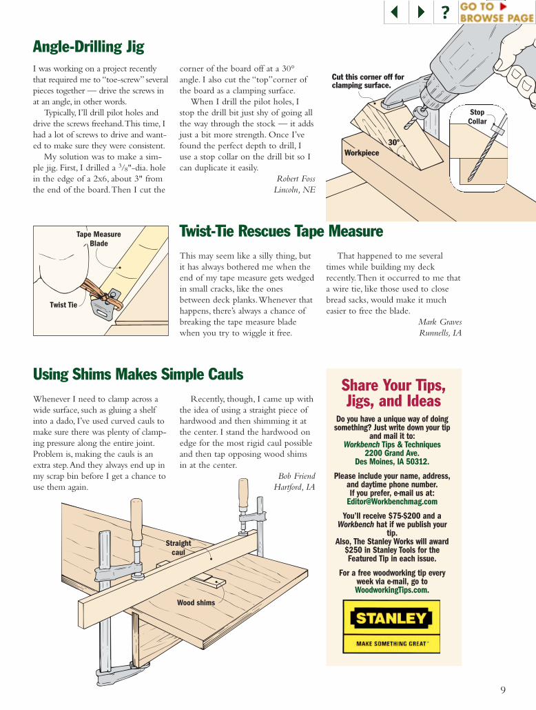
Angle-Drilling Jig
Using Shims Makes Simple Cauls
Twist-Tie Rescues Tape Measure
I was working on a project recentlythat required me to “toe-screw” severalpieces together — drive the screws inat an angle, in other words.
Typically, I’ll drill pilot holes anddrive the screws freehand.This time, Ihad a lot of screws to drive and want-ed to make sure they were consistent.
My solution was to make a sim-ple jig. First, I drilled a 3/8"-dia. holein the edge of a 2x6, about 3" fromthe end of the board.Then I cut the
corner of the board off at a 30°angle. I also cut the “top”corner ofthe board as a clamping surface.
When I drill the pilot holes, Istop the drill bit just shy of going allthe way through the stock — it addsjust a bit more strength. Once I’vefound the perfect depth to drill, Iuse a stop collar on the drill bit so Ican duplicate it easily.
Robert FossLincoln, NE
This may seem like a silly thing, butit has always bothered me when theend of my tape measure gets wedgedin small cracks, like the onesbetween deck planks.Whenever thathappens, there’s always a chance ofbreaking the tape measure bladewhen you try to wiggle it free.
That happened to me severaltimes while building my deckrecently.Then it occurred to me thata wire tie, like those used to closebread sacks, would make it mucheasier to free the blade.
Mark GravesRunnells, IA
Wood shims
Straightcaul
Twist Tie
Tape MeasureBlade
Whenever I need to clamp across awide surface, such as gluing a shelfinto a dado, I’ve used curved cauls tomake sure there was plenty of clamp-ing pressure along the entire joint.Problem is, making the cauls is anextra step.And they always end up inmy scrap bin before I get a chance touse them again.
Recently, though, I came up withthe idea of using a straight piece ofhardwood and then shimming it atthe center. I stand the hardwood onedge for the most rigid caul possibleand then tap opposing wood shimsin at the center.
Bob FriendHartford, IA
StopCollar
PlywoodBase
Cleat
Wedges
Dowelpin
RollerBolts
Woodscrew
SideSupport
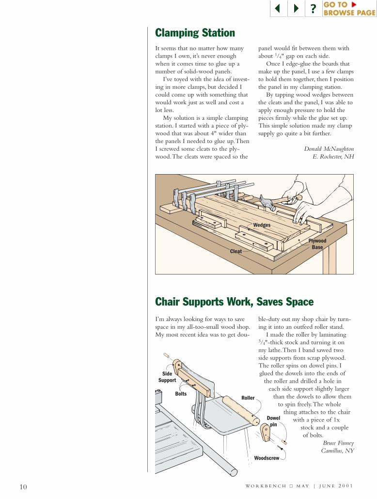
Clamping Station
Chair Supports Work, Saves Space
It seems that no matter how manyclamps I own, it’s never enoughwhen it comes time to glue up anumber of solid-wood panels.
I’ve toyed with the idea of invest-ing in more clamps, but decided Icould come up with something thatwould work just as well and cost alot less.
My solution is a simple clampingstation. I started with a piece of ply-wood that was about 4" wider thanthe panels I needed to glue up.ThenI screwed some cleats to the ply-wood.The cleats were spaced so the
panel would fit between them withabout 1/4" gap on each side.
Once I edge-glue the boards thatmake up the panel, I use a few clampsto hold them together, then I positionthe panel in my clamping station.
By tapping wood wedges betweenthe cleats and the panel, I was able toapply enough pressure to hold thepieces firmly while the glue set up.This simple solution made my clampsupply go quite a bit further.
Donald McNaughtonE. Rochester, NH
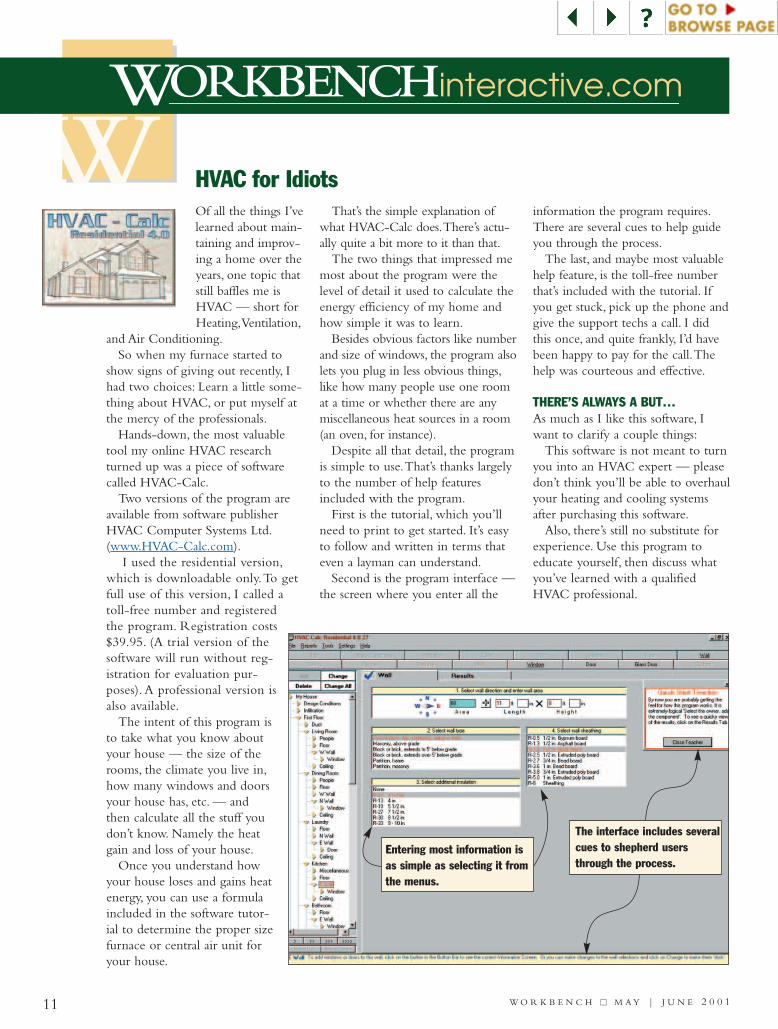
I’m always looking for ways to savespace in my all-too-small wood shop.My most recent idea was to get dou-
ble-duty out my shop chair by turn-ing it into an outfeed roller stand.
I made the roller by laminating3/4"-thick stock and turning it onmy lathe.Then I band sawed twoside supports from scrap plywood.The roller spins on dowel pins. Iglued the dowels into the ends of
the roller and drilled a hole ineach side support slightly larger
than the dowels to allow themto spin freely.The whole
thing attaches to the chairwith a piece of 1x
stock and a coupleof bolts.
Bruce FinneyCamillus, NY
10 W O R K B E N C H ■■ M A Y | J U N E 2 0 0 1
W
11 W O R K B E N C H ■■ M A Y | J U N E 2 0 0 1
WORKBENCHinteractive.com
HVAC for IdiotsOf all the things I’velearned about main-taining and improv-ing a home over theyears, one topic thatstill baffles me isHVAC — short forHeating,Ventilation,
and Air Conditioning.So when my furnace started to
show signs of giving out recently, Ihad two choices: Learn a little some-thing about HVAC, or put myself atthe mercy of the professionals.
Hands-down, the most valuabletool my online HVAC researchturned up was a piece of softwarecalled HVAC-Calc.
Two versions of the program areavailable from software publisherHVAC Computer Systems Ltd.(www.HVAC-Calc.com).
I used the residential version,which is downloadable only.To getfull use of this version, I called atoll-free number and registeredthe program. Registration costs$39.95. (A trial version of thesoftware will run without reg-istration for evaluation pur-poses). A professional version isalso available.
The intent of this program isto take what you know aboutyour house — the size of therooms, the climate you live in,how many windows and doorsyour house has, etc. — andthen calculate all the stuff youdon’t know. Namely the heatgain and loss of your house.
Once you understand howyour house loses and gains heatenergy, you can use a formulaincluded in the software tutor-ial to determine the proper sizefurnace or central air unit foryour house.
That’s the simple explanation ofwhat HVAC-Calc does.There’s actu-ally quite a bit more to it than that.
The two things that impressed memost about the program were thelevel of detail it used to calculate theenergy efficiency of my home andhow simple it was to learn.
Besides obvious factors like numberand size of windows, the program alsolets you plug in less obvious things,like how many people use one roomat a time or whether there are anymiscellaneous heat sources in a room(an oven, for instance).
Despite all that detail, the programis simple to use.That’s thanks largelyto the number of help featuresincluded with the program.
First is the tutorial, which you’llneed to print to get started. It’s easyto follow and written in terms thateven a layman can understand.
Second is the program interface —the screen where you enter all the
information the program requires.There are several cues to help guideyou through the process.
The last, and maybe most valuablehelp feature, is the toll-free numberthat’s included with the tutorial. Ifyou get stuck, pick up the phone andgive the support techs a call. I didthis once, and quite frankly, I’d havebeen happy to pay for the call.Thehelp was courteous and effective.
THERE’S ALWAYS A BUT…As much as I like this software, Iwant to clarify a couple things:
This software is not meant to turnyou into an HVAC expert — pleasedon’t think you’ll be able to overhaulyour heating and cooling systemsafter purchasing this software.
Also, there’s still no substitute forexperience. Use this program toeducate yourself, then discuss whatyou’ve learned with a qualifiedHVAC professional.
Leave me
some space to
do some call-
out arrows
Entering most information isas simple as selecting it fromthe menus.
The interface includes severalcues to shepherd usersthrough the process.

12W O R K B E N C H ■■ M A Y | J U N E 2 0 0 1
RepairClinic.com Offers Appliance Know-How
Site To Watch
There are three undeniable truthsabout household appliances:
1.They die in packs.2.They always die on the week-
ends while the service centers are closed.
3.No matter how many timesyou open and close their doors,spin their knobs, flip theirswitches, or push their buttons,they will not fix themselves.
Considering all that, the typicalDIY homeowner is helpless against abroken appliance (or broken appli-ances, see rule #1).
Now, however, there’s a Web sitethat aims to level the playing field —www.RepairClinic.com.
RepairClinic.com, whichlaunched in January of 2000, usesinteractive features such as their PartDetective and Repair Guru to helpthe “appliance-challenged” to firstidentify their problems and then tofix them. Conveniently, they’ll evensell you the parts and repair manualsyou need to finish the job. (Hey,something has to be for sale, folks.)
The Part Detective is one of themost useful online tools I’ve seen onany of the sites I’ve assessed forWorkbenchInteractive.com. Even ifyou know almost nothing aboutyour particular appliance, you canuse the Part Detectives selectionmenus to describe the part you
need. (Is it all plastic or all metal? Isit all one color? What is the part’slongest dimension?) From that, you’llget a list of parts (many with pic-tures) that match your criteria. Itshould be pretty easy to find a matchfrom those.
The Repair Guru is another prob-lem-solving feature on the site. Hereagain, you answer a series of ques-tions about what your appliance is(or isn’t) doing, and the Guru offersa few things for you to check out onyour machine.
If all else fails, you can e-mail theAppliance Guru with the details ofyour specific problem.They answermost questions within one day.
Among the promotional newsreleases in RepairClinic.com’s“Newsroom,” there was one that
listed appliance mythsand facts that contra-dict them. Here are afew of my favorites:
MYTH: Gasrange burnersheat faster than
electric ones.FACT: Most electric burners willactually heat things faster thangas, but gas burners allow forfaster changes in temperature,thus more control.MYTH: Refrigerators naturallylose freon over time and need tobe recharged.FACT:The freon or other refrig-erant should never leak out, dis-sipate or break down.MYTH:Today’s laundry deter-gents work just as well in coldwater as warm or hot.FACT: In northern climates, theincoming cold water can be ascold as 40 degrees. Moderndetergents work best at tempera-tures of 60 degrees and higher.You may want to use the warmcycle in the winter for moreeffective cleaning.
Appliance MythsDebunked
www.TomboyTools.comToday’s Tomboy is a competent, con-fident DIYer — or at least that’s howthe women of TomboyTools.comdefine the term.The women behindthis new Web site hope they’ll be able
to strike a chord with other women no longer satisfiedwith settling for tools designed for men.
But that doesn’t mean these women want frilly tools— the site motto is “No Pink Tools!”What they wantare tools designed for the way women use them.
The site is brand new, so there isn’t much going onyet, but the site is worth keeping an eye on for a differentperspective on tools.The idea is certainly long overdue.
The winner of theWorkbench Ultimate ToolkitGiveaway is:2nd Lt. Kevin Wiley, USAF.
Kevin hails from Oak Park,IL and was stationed atKirtland AFB when we con-tacted him. Congratulations to2nd Lt.Wiley and thanks toall who entered the drawing.
Keep an eye on this spaceand our Web site for moretool giveaways fromWorkbench coming soon.
Toolkit Winner!
13 W O R K B E N C H ■■ M A Y | J U N E 2 0 0 1
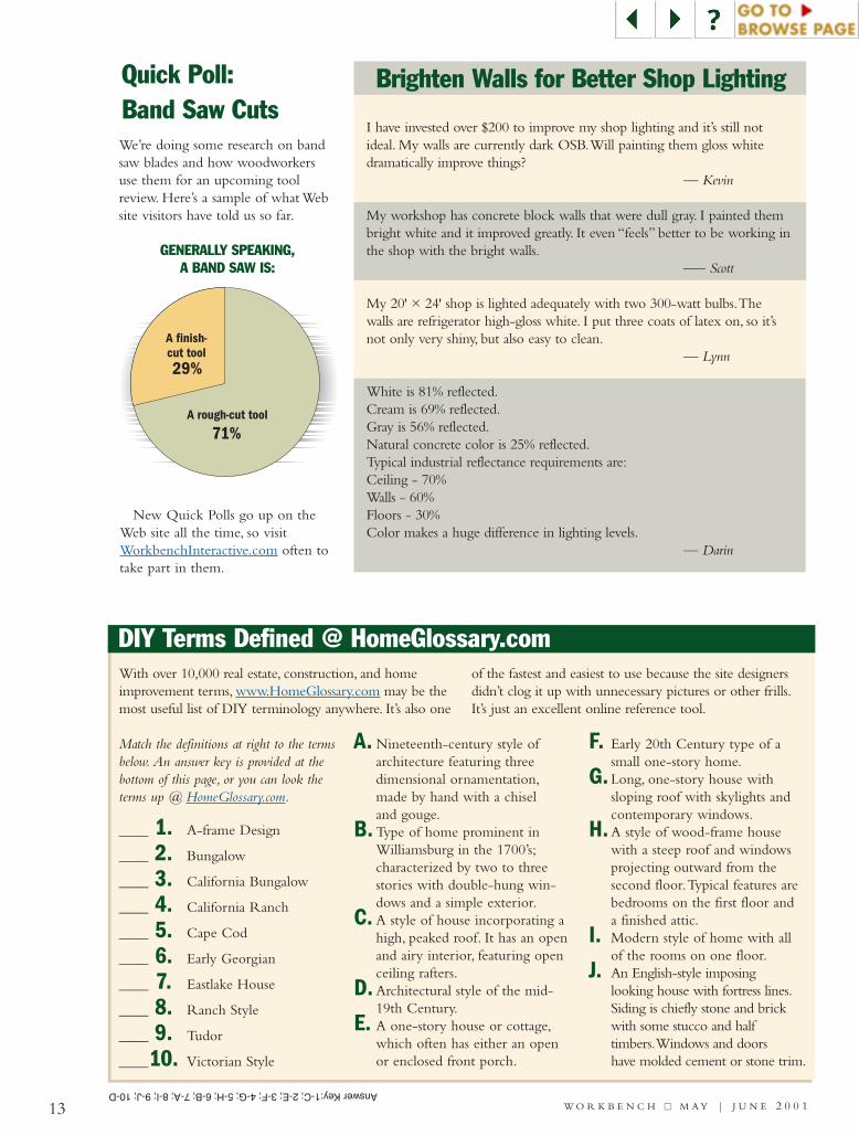
Quick Poll:Band Saw CutsWe’re doing some research on bandsaw blades and how woodworkersuse them for an upcoming toolreview. Here’s a sample of what Website visitors have told us so far.
New Quick Polls go up on theWeb site all the time, so visitWorkbenchInteractive.com often totake part in them.
DIY Terms Defined @ HomeGlossary.comWith over 10,000 real estate, construction, and homeimprovement terms, www.HomeGlossary.com may be themost useful list of DIY terminology anywhere. It’s also one
of the fastest and easiest to use because the site designersdidn’t clog it up with unnecessary pictures or other frills.It’s just an excellent online reference tool.
____ 1. A-frame Design
____ 2. Bungalow
____ 3. California Bungalow
____ 4. California Ranch
____ 5. Cape Cod
____ 6. Early Georgian
____ 7. Eastlake House
____ 8. Ranch Style
____ 9. Tudor
____10. Victorian Style
A. Nineteenth-century style ofarchitecture featuring threedimensional ornamentation,made by hand with a chisel and gouge.
B. Type of home prominent inWilliamsburg in the 1700’s;characterized by two to threestories with double-hung win-dows and a simple exterior.
C. A style of house incorporating ahigh, peaked roof. It has an openand airy interior, featuring openceiling rafters.
D. Architectural style of the mid-19th Century.
E. A one-story house or cottage,which often has either an openor enclosed front porch.
F. Early 20th Century type of asmall one-story home.
G. Long, one-story house withsloping roof with skylights andcontemporary windows.
H.A style of wood-frame housewith a steep roof and windowsprojecting outward from the second floor.Typical features arebedrooms on the first floor anda finished attic.
I. Modern style of home with allof the rooms on one floor.
J. An English-style imposinglooking house with fortress lines.Siding is chiefly stone and brickwith some stucco and halftimbers.Windows and doorshave molded cement or stone trim.
Match the definitions at right to the termsbelow. An answer key is provided at thebottom of this page, or you can look theterms up @ HomeGlossary.com.
Brighten Walls for Better Shop Lighting
I have invested over $200 to improve my shop lighting and it’s still notideal. My walls are currently dark OSB.Will painting them gloss whitedramatically improve things?
— Kevin
My workshop has concrete block walls that were dull gray. I painted thembright white and it improved greatly. It even “feels” better to be working inthe shop with the bright walls.
–— Scott
My 20' × 24' shop is lighted adequately with two 300-watt bulbs.Thewalls are refrigerator high-gloss white. I put three coats of latex on, so it’snot only very shiny, but also easy to clean.
— Lynn
White is 81% reflected.Cream is 69% reflected.Gray is 56% reflected.Natural concrete color is 25% reflected.Typical industrial reflectance requirements are:Ceiling - 70%Walls - 60%Floors - 30%Color makes a huge difference in lighting levels.
— Darin
A rough-cut tool
29%
71%
A finish-cut tool
GENERALLY SPEAKING, A BAND SAW IS:
Answer Key:1-C;2-E;3-F;4-G;5-H;6-B;7-A;8-I;9-J;10-D

14 W O R K B E N C H ■■ M A Y | J U N E 2 0 0 0
A Simple Crosscut Sled for Cutting Wide Panels
In The Shop
Fence(1 " x 1 ")!/2 #/4
Base( " ply. x16" x 30")#/4
Runner( " x widthof slot x 20")
#/8
Addchamfer fordust relief.
Fence
Base Runner
The miter gauge that comes withmost table saws is fine for crosscut-ting a narrow board. But there’s aproblem when it comes to workingwith wide panels like those usedfor the top and the shelf of theBedside Table on page 22.
When you pull the miter gaugeout, the head starts to wobblebecause the bar isn’t fully sup-ported in the slot.That makescrosscutting not only difficult, butpotentially dangerous also.
One way to get around that isto use a simple crosscut sled. Itworks like a giant miter gauge,allowing you to crosscut wide pan-els safely and accurately.
The panel rests on a large, flatbase that you slide across the sawtable.A pair of runners guides thesled and the workpiece smoothlythrough the saw blade.And a fenceon the back edge of the sledensures square cuts.
BUILD THE BASETo build the crosscut sled, start bycutting a piece of 3/4"-thick ply-wood for the base. (I made mybase 16" × 30".)
Next, cut a hardwood runner tofit in the miter gauge slot of yourtable saw.The goal is to size therunner so it slides smoothly in theslot. Notice that the runner sticksout from the end of the base 4" to5".This adds to the stability of thesled, allowing you to pull the baseback far enough in the slot to holdwider panels.
Now lower the table saw bladeand position the runner in themiter slot.Then set the base downover the runner, aligning it just pastthe table saw blade. Mark the loca-tion of the runner on the front andback of the base. Now flip the baseover and drill and countersink for#6 × 3/4" Fh woodscrews.Then
glue and screw the runner to thebottom, see Detail a.
To help keep the sled aligned, asecond runner is added.This onerides against the edge of the exten-sion wing on the table saw, see photoand the drawing above.To positionit, use a couple of spring clamps tohold it.Then screw it in place.
Once both runners are attached,place the sled on your saw andtrim off the right edge of the base.
ADD A FENCEFor the fence, I used a piece of 2xstock ripped to width, with a
chamfer routed on the bottomedge for dust relief (Detail a).
To position the fence on thesled so it’s square to the blade, use aframing square, see the drawing.Finally, drill and countersink for#8 × 11/2" Fh woodscrews, andthen screw the fence to the base.
NOTE: Fence is madefrom 2x stock.
a.

Cam
StopNut
ThreadedRod
Base
ClampingBar
Cam
TemplateStop
ClampingBar
Stop
15 W O R K B E N C H ■■ M A Y | J U N E 2 0 0 1
Template!/2"
Dovetail Bit
!/2"
Bushing
StopNuts
WingNut
Drawer Side
Template
AdjustableStop Block
BottomEdge
Lay out drawer pieces on bench withinsides face up. Then label all thepieces and number matching corners.
Adjust the stop block so the edge ofthe front workpiece is centered in thefirst notch of the template.
Stop nuts should be adjusted in or outso fingers of template are centered overthe “joint line” between the two pieces.
Cutting Accurate Half-Blind DovetailsThe drawer in the BedsideTable that’s featured onpage 22 is held togetherwith half-blind dovetailjoints. One quick, accu-rate way to cut this typeof joint is with a router, a1/2" dovetail bit, a guidebushing, and a specialdovetail jig.
DOVETAIL JIGThe half-blind dovetail jigis a comb-shaped tem-plate that fits on a base,see drawing.The base hasclamping bars to hold theworkpieces in place whilethe router is guided inand out of the “fingers”
on the template to cut evenlyspaced dovetails on a drawer’s front,back and sides. Note:The proce-dures outlined here are for usingthe Woodsmith Dovetail Jig (seeSources, page 59), but it’s similar formost half-blind dovetail jigs.
To cut dovetail joints with arouter and template requires a littleplanning ahead. For example, thedrawer for the table is exactly 31/2"wide. I planned for this width so theopening would accommodate adrawer joined with router-cut dove-tails.That is, the width (height) ofthe drawer front has to be a multipleof 7/8".This produces a dovetail jointthat’s symmetrical both on the topand bottom edges, see the photoabove. Note:The drawers for theBedside Table are flush front drawers,
meaning the width of all the drawerpieces will be the same.
Another consideration is the lengthof the drawer pieces.To make surethe corners are square, check that thedrawer front and back, as well as thedrawer sides, are equal lengths. Oncethe pieces are cut to size, lay them
out and label the bottom edge ofeach piece, as shown below.Also,number the matching corners.
SET UPSetting up the jig takes some trialand error, so I first used some scrappieces that are the same thickness
2 3
NOTE: Label drawerpieces on inside face.
Set up stopson both ends
of jig.
Half of drawerjoints cut on left,
half on right.
DRAWER LAYOUT
DOVETAIL JIG
1
a.
16W O R K B E N C H ■■ M A Y | J U N E 2 0 0 0
!/2" Dovetail Bit
Make light passto prevent chipout.
BitMove routerin and out.
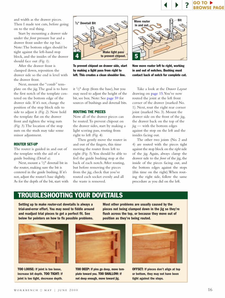
TROUBLESHOOTING YOUR DOVETAILS
TOO LOOSE: If joint is too loose,increase bit depth. TOO TIGHT: Ifjoint is too tight, decrease depth.
To prevent chipout on drawer side, startby making a light pass from right toleft. This creates a clean shoulder line.
Now move router left to right, workingin and out of notches. Bushing mustcontact back of notch for complete cut.
TOO DEEP: If pins go deep, move tem-plate toward you. TOO SHALLOW: Ifnot deep enough, move toward jig.
OFFSET: If pieces don’t align at topor bottom, they may not have beentight against the stops.
Setting up to make router-cut dovetails is always atrial-and-error effort. You may need to fiddle aroundand readjust trial pieces to get a perfect fit. Seebelow for pointers on how to fix possible problems.
Most other problems are usually caused by thepieces not being clamped down in the jig so they’reflush across the top, or because they move out ofposition as they’re being routed.
and width as the drawer pieces.Then I made test cuts, before goingon to the real thing.
Start by mounting a drawer sideunder the front pressure bar and adrawer front under the top bar.Note:The bottom edges should betight against the left-hand stopblock, and the insides of the drawershould face out (Fig. 1).
After the drawer front isclamped down, reposition thedrawer side so the end is level withthe drawer front.
Next, mount the “comb” tem-plate on the jig.The goal is to havethe first notch of the template cen-tered on the bottom edge of thedrawer side. If it’s not, change theposition of the stop block side toside to adjust it (Fig. 2). Now holdthe template flat on the drawerfront and tighten the wing nuts(Fig. 3).The location of the stopnuts on the studs may take someminor adjustment.
ROUTER SET-UPThe router is guided in and out ofthe template with the aid of aguide bushing (Detail a).
Next, mount a 1/2" dovetail bit inthe router, making sure the bit iscentered in the guide bushing. If it’snot, adjust the router’s base slightly.As for the depth of the bit, start with
it 1/2" deep (from the base), but youmay need to adjust the height of thebit, see box. Note: See page 59 forsources of bushings and dovetail bits.
ROUTING THE PIECESNow all of the drawer pieces canbe routed.To prevent chipout onthe drawer sides, start by making alight scoring pass, routing fromright to left (Fig. 4).
Then gently move the router inand out of the fingers, this timemoving the router from left toright (Fig. 5).You should be able tofeel the guide bushing stop at theback of each notch.After routing,but before removing the piecesfrom the jig, check that you’verouted each socket evenly and allthe waste is removed.
Take a look at the Drawer Layoutdrawing on page 15.You’ve nowrouted the joint at the left frontcorner of the drawer (marked No.1). Next, rout the right rear cornerjoint (marked No. 3). Mount thedrawer side on the front of the jig,the drawer back on the top of thejig — with the bottom edgesagainst the stop on the left and theinsides facing out.
The other two joints (No. 2 and4) are routed with the pieces tightagainst the stop block on the right sideof the jig. Again, always clamp thedrawer side to the front of the jig, theinside of the pieces facing out, andthe bottom edges against the stops(this time on the right).When rout-ing the right side, follow the sameprocedure as you did on the left.
4 5
17 W O R K B E N C H ■■ M A Y | J U N E 2 0 0 0
RipFence
Shoe
STEP 3: Pushworkpiece and
sled through blade.
STEP 1: Fitworkpiecein notchformedby shoe.
Shoe
PushSled
ThinStrip
Workpiece
STEP 2:Position
Rip Fenceto cut
strip ofdesired width.
Cutting Thin Strips Safely
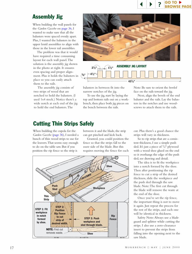
Assembly Jig
When building the cupola for theGarden Gazebo (page 36), I needed abunch of thin wood strips to use forthe louvers.That seems easy enoughto do on the table saw. But if youposition the rip fence so the strip is
between it and the blade, the stripcan get pinched and kick back.
Granted, you could position thefence so that the strips fall to thewaste side of the blade. But thisrequires moving the fence for each
cut. Plus there’s a good chance thestrips will vary in thickness.
So to rip strips that are a consis-tent thickness, I use a simple pushsled. It’s just a piece of 3/4" plywoodwith a wood shoe glued on the endso it overhangs the edge of the pushsled, see drawing and detail.
The idea is to fit the workpieceinto a notch formed by the shoe.Then after positioning the ripfence to cut a strip of the desiredthickness, slide the workpiece andthe push sled through the sawblade. Note:The first cut throughthe blade will remove the waste atthe end of the shoe.
Once you’ve set the rip fence,the important thing is not to moveit again. Just repeat the process forthe rest of the strips, and each onewill be identical in thickness.
Safety Note:Always use a bladeguard and splitter while cutting thestrips. I also use a zero-clearanceinsert to prevent the strips fromfalling into the opening next to thesaw blade.
When building the wall panels forthe Garden Gazebo on page 36, Iwanted to make sure that all thebalusters were spaced evenly apart.Plus, I wanted the balusters in theupper lentil assemblies to align withthose in the lower rail assemblies.
The problem was that it wouldhave required a time consuminglayout for each wall panel.Thesolution is the assembly jig shownin the photo at right. It ensureseven spacing and proper align-ment. Plus it holds the balusters inplace so you can easily attachthem to the rails.
The assembly jig consists oftwo strips of wood that arenotched to hold the balusters. (Iused 1x4 stock.) Notice there’s awide notch at each end of the jigto hold the end balusters.The
balusters in between fit into thenarrow notches of the jig.
To use the jig, start by laying thetop and bottom rails out on a work-bench, then place both jig pieces onthe bench between the rails.
Note: Be sure to orient the beveledface on the rails toward the jig.
Next, align the bevels of the endbaluster and the rails. Lay the balus-ters in the notches and use wood-screws to attach them to the rails.
2 "!/2 1 "!/2
4 "!/2#/8"
43 "!/2
ASSEMBLY JIG LAYOUT
NOTE: First cut removes waste.

W O R K B E N C H ■■ M A Y | J U N E 2 0 0 118
D E C K - B U I L D I N G C O N T E S T
Dynamite Decks! Enter the Workbench and California Redwood Association’sdeck-building contest — share in over $6,000 in cash and prizes.
Deck designs have certainlychanged during the pastfew years.They’re no longer
just a place to barbecue or relax.They’ve become total outdoor living
spaces — complete with grillingcenters, conversation pits, uniquelighting, even hot tubs and spas.Thedecks shown on the following pagesare a perfect example of how
changes in lifestyle have influencedthe way decks are being designed.Multi-level spaces now allow severalactivities to go on at the same time.Elaborate wrap-around decks pro-
ELEGANT WRAP-AROUND ... SLEEK RAILING
1. This curved redwood deck wrapsinvitingly around the front and side ofa rustic mountain home.
2. Horizontal brushed stainless steelrails give this multi-level deck a sleek,contemporary look.
2
1

W O R K B E N C H ■■ M A Y | J U N E 2 0 0 1 19
vide access to the house at a numberof different places. And built-in barsand barbecues provide places foroutdoor entertaining.
More than ever before, decks havealso become a reflection of theirowners’ personalities. Take a quicktour through the photos on thesepages to see some ingenious wayshomeowners all across the countryare personalizing their decks. You’llfind things like privacy screens, hand-crafted lighting fixtures, and evenmini-kitchens and hot tubs.
EVERYBODY LOVES A CONTESTIf you’ve always wanted to incorpo-rate these types of unique featuresinto your own deck-building pro-jects, we’ve got just the ticket. Youguessed it — a deck-building contest.
Here’s your chance to show offyour design and building skills. Butthis is more than just a contest wherewe give away cash and prizes. Keepreading to learn more.
For the first time, Workbenchmagazine has teamed-up with theCalifornia Redwood Association to
sponsor the ultimate deck-buildingcontest. Together, we’re going tochoose the “Best Decks in America”— from New Orleans to New York,and from Minneapolis to the moun-tains of Colorado.
The decks belonging to the win-ners of the contest will be featuredin a spring 2002 issue of Workbenchmagazine. If you take a look at page21, you’ll find the official “EntryRules” for the contest. So whatmakes for a winning deck? Turn thepage to find out.
SPA ... VERANDA ... CURVES
3. A built-in spa and solarium/sun roompartially enclosed in glass highlight thisColorado deck.
4. This 1,890-square-foot redwooddeck wraps around the house,reminiscent of an Australian veranda(the owner’s native country).
5. Elements of this elegantly designeddeck include a graceful curving shapewith knotty redwood combined withcopper accents.
4
5
3

20 W O R K B E N C H ■■ M A Y | J U N E 2 0 0 1
GATE ... RAILS ... LIGHTS
6. A focal point of this deck is theJapanese-style, redwood entry gate.
7. Notice the rich blend of this shiningcopper and redwood railing.
8. Lit from within, these decorative posts provide a dramatic show at night.
BENCH ... PLANTERS ... BAR
9. These built-in benches feature curvedbacks and lattice inserts for the arms.
10. Built-in six-sided planters provide lotsof space for flowers and splashes of color.
11. This ground-level wet bar with ceramictile counter is part of a three-tiered, totalentertainment deck.
DETAILS THAT COUNTSo what are we looking for in thewinning decks? Certainly qualityconstruction and creative design areimportant. But as with most projects,it’s the details that really make a bigdifference — those interesting andunique things that can turn an ordi-nary deck into something special.
Perhaps it’s a lattice gate leading toa secluded garden spot, a circularbench with built-in storage, or asunken, Japanese-style fire pit. Maybeyou’ve come up with a clever way toscreen your deck from the neighbors’view or provide shading for a built-indining area. It could even be a newtwist on outdoor lighting or a cleverrailing treatment.
Here’s the bonus part of the con-test. Even if you don’t enter, you’llwant to keep your eyes peeled forthe winning decks. That’s becausewe plan to provide step-by-stepinstructions and detailed illustrationsof the unique design elements of thewinning decks. Then you’ll be ableto incorporate these features intoyour next deck-building project.
DON’T FORGET TO ENTERIf you know someone who has areally neat deck feature, be sure totell them about this contest. In fact,tell all your neighbors and friends— the more decks, the better.
We can’t wait to see all thosedynamite decks around the country.Who knows, perhaps we’ll be hon-oring you as one of our winnersnext year. Good luck!
7
8
10
11
9
6
CaliforniaRedwoodAssociation
21W O R K B E N C H ■■ M A Y | J U N E 2 0 0 1
REDWOOD DECK CONTESTENTER TO WIN!
Send entries to:Workbench/California Redwood Association Deck Contest
405 Enfrente Drive, Suite 200, Novato, CA 94949Telephone: 415-382-0662
Name_____________________________________
Firm Name ________________________________(for building and design professionals only)
Address ___________________________________
City ______________________________________
State __________ Zip _______________________
Phone(day)___________ (evening) _________________
Date project was completed ____________________
Date enclosed photos were taken ________________
Please circle all that apply:The person entering is the: Homeowner Pro builder
Pro designer/architectThe deck was designed by a: Homeowner ProfessionalThe deck was built by a: Homeowner Professional
Enter Me in the Workbench/CaliforniaRedwood Association Deck Contest
(Please print or type)
PRIZES: Three cash prizes will be awarded, and all winners will receive atleast one additional prize as well. The grand-prize winner will receive acash prize of $3,000; the first runner-up will receive a cash prize of$2,000; and the second runner-up will receive a cash prize of $1,000. Thethree winning decks will be featured in a Spring 2002 issue of Workbenchmagazine and all prizes will be distributed at the time of publication.WHO CAN ENTER: The contest is open to homeowners who have built adeck or had one built for them, as well as to contractors, architects anddesigners who have built or designed a deck for a client as long as theclient/homeowner consents to the submission. Redwood must have beenused in the construction of the deck, preferably on visible surfaces. Othermaterials may have been used for structural support and design accents.The deck must be no more than three years old and cannot have beenpublished elsewhere. In addition, the deck must be able to be pho-tographed attractively. Employees of Workbench magazine and CaliforniaRedwood Association are not eligible to enter.HOW TO ENTER: Fill out the entry coupon. Enclose several different pho-tographs of your deck; there is no limit on the number you may submit.Color prints are preferred, but slides are acceptable. If the deck isattached to a house, include a shot that clearly shows the two structurestogether. The photographs must have been taken in 2001 to show the cur-rent condition of the deck.
Also include a dimensional drawing that shows the nominal sizes of piers,posts, beams, joists, decking and railing members and their spacing. Asketch will suffice if it is labeled with critical dimensions. Also include alist of all materials used: redwood, other lumber or plywood, hardware andfinish and accent materials, such as brick, stone or tile.
You must also furnish a written description of the design goals and howthey were achieved, including any special design or construction problemsand solutions. Entries must include all of the required enclosures to qualifyfor the contest. Models and/or presentation boards over 18x24 in.-with theexception of blueprints-will not be accepted.ENTRY DEADLINE: Entries must be delivered to the address shown on thecoupon by August 31, 2001. No entries will be acknowledged except thethree winners, and none will be returned unless accompanied by a writtenrequest and a self-addressed envelope with proper postage.TERMS: The submission of an entry signifies your agreement to the follow-ing: (1) you warrant that you, as the entrant in the contest or with the writ-ten consent of others, have the authority to make the submission and grantthe rights herein granted; (2) you warrant that the material submitted withthe entry, including the publication thereof by Workbench magazine andthe California Redwood Association, will not violate or infringe upon therights of others; (3) you warrant that the material as submitted with theentry, including designs and photographs, have not been previously pub-lished and distributed in any manner, including both printed and electronicmedia; and (4) you will not permit the material to be published in anyother publication, whether printed or electronic media, until after December31, 2001 for non-winners and December 31, 2002 for prize winners. If youare a prize winner, in consideration thereof, you grant to Workbench maga-zine and the California Redwood Association the exclusive right and licenseto reproduce and publish in both printed and electronic media all materialsubmitted with the entry, along with your name and location, and grant rea-sonable access for photographs to be made by representatives ofWorkbench magazine and the California Redwood Association, untilDecember 31, 2002, and, thereafter, such rights as granted shall continueon a non-exclusive basis. FURTHER, each entrant agrees to indemnifyWorkbench magazine and the California Redwood Association in the eventthe entrant violates any of the foregoing terms.
HOW DECKS ARE JUDGED: Contest entries will be judged by representa-tives of Workbench magazine published by August Home PublishingCompany and the California Redwood Association. The judges will also belooking for the most attractive and interesting uses of redwood in the deckprojects. The winners will be chosen based on design, construction quality,innovative details and overall appearance in relation to the home and yard.The determination of the judges will be final. Winners will be notified byOctober 1, 2001.
Send us photos and drawings of your deckprojects for a chance to share in over
$6,000 in cash and prizes!
Woodworking To Improve Your Home
TM
22
W O O D W O R K I N G
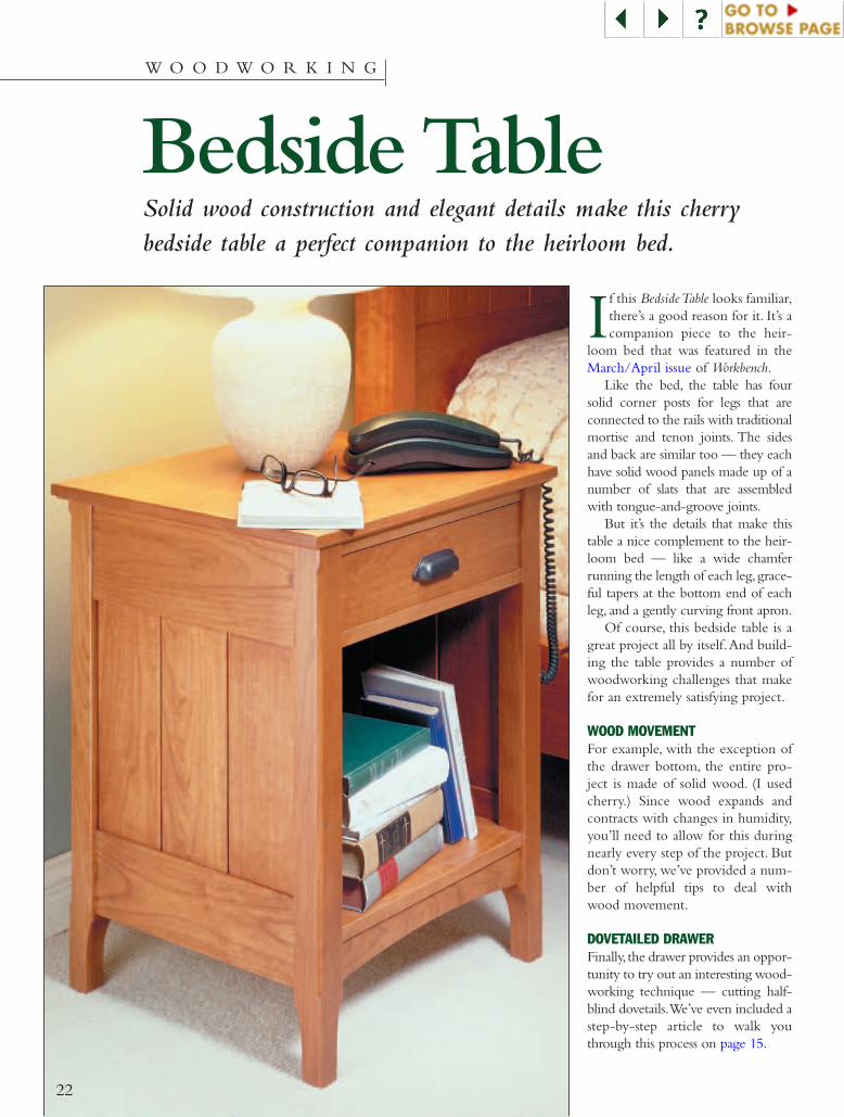
Bedside TableSolid wood construction and elegant details make this cherrybedside table a perfect companion to the heirloom bed.
If this Bedside Table looks familiar,there’s a good reason for it. It’s acompanion piece to the heir-
loom bed that was featured in theMarch/April issue of Workbench.
Like the bed, the table has foursolid corner posts for legs that areconnected to the rails with traditionalmortise and tenon joints. The sidesand back are similar too — they eachhave solid wood panels made up of anumber of slats that are assembledwith tongue-and-groove joints.
But it’s the details that make thistable a nice complement to the heir-loom bed — like a wide chamferrunning the length of each leg,grace-ful tapers at the bottom end of eachleg, and a gently curving front apron.
Of course, this bedside table is agreat project all by itself.And build-ing the table provides a number ofwoodworking challenges that makefor an extremely satisfying project.
WOOD MOVEMENTFor example, with the exception ofthe drawer bottom, the entire pro-ject is made of solid wood. (I usedcherry.) Since wood expands andcontracts with changes in humidity,you’ll need to allow for this duringnearly every step of the project. Butdon’t worry, we’ve provided a num-ber of helpful tips to deal withwood movement.
DOVETAILED DRAWERFinally, the drawer provides an oppor-tunity to try out an interesting wood-working technique — cutting half-blind dovetails.We’ve even included astep-by-step article to walk youthrough this process on page 15.
W O R K B E N C H ■■ M A Y | J U N E 2 0 0 1
F
H
Bin pull
FrontRails
C
LowerSide Rail
E
Top
Shelf isnotched to
fit around Legs.
Leg
Leg
A
A
FrontApron
B
SideStarter
Slat
Legs are taperedon both inside faces.
Taper
M
SideSlats
I
BackStarter
Slat
J
BackSlats
K
UpperSide Rail
SpacerKicker
D
#8 x 1"Fh Woodscrew
Shelf
QDrawer
SideP
R
DrawerFront
DrawerBack
DrawerBottom
N
L
#8 x 1 "Fh Woodscrew
!/4
O
LowerBackRail
Upper BackRail
G
P
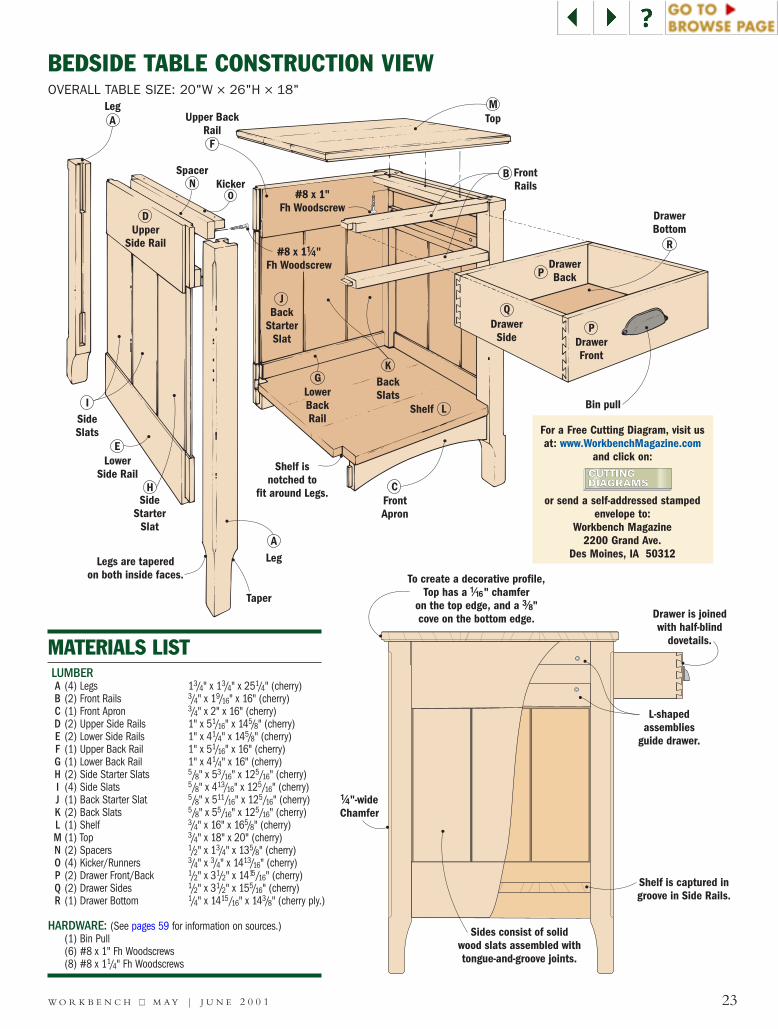
MATERIALS LISTLUMBERA (4) Legs 13/4" x 13/4" x 251/4" (cherry)B (2) Front Rails 3/4" x 19/16" x 16" (cherry)C (1) Front Apron 3/4" x 2" x 16" (cherry)D (2) Upper Side Rails 1" x 51/16" x 145/8" (cherry)E (2) Lower Side Rails 1" x 41/4" x 145/8" (cherry)F (1) Upper Back Rail 1" x 51/16" x 16" (cherry)G (1) Lower Back Rail 1" x 41/4" x 16" (cherry)H (2) Side Starter Slats 5/8" x 53/16" x 125/16" (cherry)I (4) Side Slats 5/8" x 413/16" x 125/16" (cherry)J (1) Back Starter Slat 5/8" x 511/16" x 125/16" (cherry)K (2) Back Slats 5/8" x 55/16" x 125/16" (cherry)L (1) Shelf 3/4" x 16" x 165/8" (cherry)M (1) Top 3/4" x 18" x 20" (cherry)N (2) Spacers 1/2" x 13/4" x 135/8" (cherry)O (4) Kicker/Runners 3/4" x 3/4" x 1413/16" (cherry)P (2) Drawer Front/Back 1/2" x 31/2" x 1415/16" (cherry)Q (2) Drawer Sides 1/2" x 31/2" x 155/16" (cherry)R (1) Drawer Bottom 1/4" x 1415/16" x 143/8" (cherry ply.)
HARDWARE: (See pages 59 for information on sources.)(1) Bin Pull(6) #8 x 1" Fh Woodscrews(8) #8 x 11/4" Fh Woodscrews
23
L-shapedassemblies
guide drawer.
Shelf is captured ingroove in Side Rails.
Drawer is joinedwith half-blind
dovetails.
To create a decorative profile,Top has a " chamfer
on the top edge, and a "cove on the bottom edge.
!/16
#/8
!/4"-wideChamfer
Sides consist of solidwood slats assembled withtongue-and-groove joints.
BEDSIDE TABLE CONSTRUCTION VIEWOVERALL TABLE SIZE: 20"W × 26"H × 18"
For a FreeCuttingDiagram
For a Free Cutting Diagram, visit usat: www.WorkbenchMagazine.com
and click on:
or send a self-addressed stampedenvelope to:
Workbench Magazine2200 Grand Ave.
Des Moines, IA 50312
!/8"Roundover
4"4 "%/8
3 "!/2 3 "!/2
!/4"!/4"
&/16"
1 "#/4
4 "!!/16 4 "!!/16!/2" !/2"
&/16"
1 "#/4
(/16"
(/16"
1 "!/4
&/16"
ALegs
Open mortiseshold Upper Rails.
Mortises forLower Rails.
Front ApronMortise
Grooves forSide and
Back Panels.
Front Railmortises arehorizontal.
4 "!/24"!/4"
1 "!/2
%/8"
!/4"
&/16"
(/16"(/16"
1 "#/4
1 "#/4
4 "!!/164 "(/16
!/2"!/2"
!/4"
&/16"
3 "!/2
4 "%/8
1 "!/4
&/16"
1 "!/16
1 "!/16
!/8"Roundover
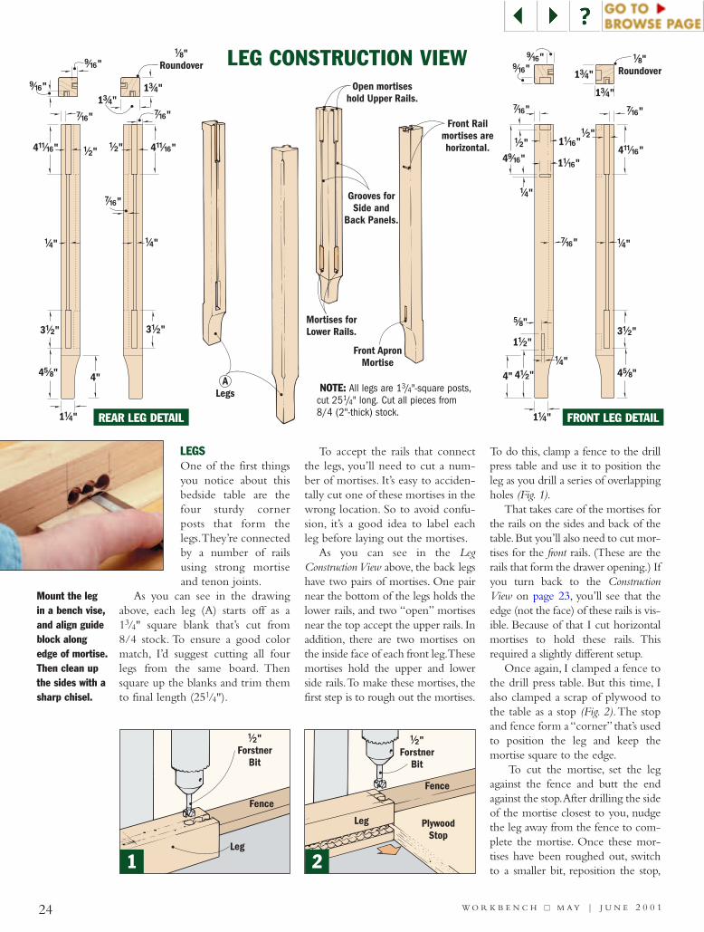
LEGSOne of the first thingsyou notice about thisbedside table are thefour sturdy cornerposts that form thelegs.They’re connectedby a number of railsusing strong mortiseand tenon joints.
As you can see in the drawingabove, each leg (A) starts off as a13/4" square blank that’s cut from8/4 stock. To ensure a good colormatch, I’d suggest cutting all fourlegs from the same board. Thensquare up the blanks and trim themto final length (251/4").
To accept the rails that connectthe legs, you’ll need to cut a num-ber of mortises. It’s easy to acciden-tally cut one of these mortises in thewrong location. So to avoid confu-sion, it’s a good idea to label eachleg before laying out the mortises.
As you can see in the LegConstruction View above, the back legshave two pairs of mortises. One pairnear the bottom of the legs holds thelower rails, and two “open” mortisesnear the top accept the upper rails. Inaddition, there are two mortises onthe inside face of each front leg.Thesemortises hold the upper and lowerside rails.To make these mortises, thefirst step is to rough out the mortises.
To do this, clamp a fence to the drillpress table and use it to position theleg as you drill a series of overlappingholes (Fig. 1).
That takes care of the mortises forthe rails on the sides and back of thetable.But you’ll also need to cut mor-tises for the front rails. (These are therails that form the drawer opening.) Ifyou turn back to the ConstructionView on page 23, you’ll see that theedge (not the face) of these rails is vis-ible. Because of that I cut horizontalmortises to hold these rails. Thisrequired a slightly different setup.
Once again, I clamped a fence tothe drill press table. But this time, Ialso clamped a scrap of plywood tothe table as a stop (Fig. 2).The stopand fence form a “corner” that’s usedto position the leg and keep themortise square to the edge.
To cut the mortise, set the legagainst the fence and butt the endagainst the stop.After drilling the sideof the mortise closest to you, nudgethe leg away from the fence to com-plete the mortise. Once these mor-tises have been roughed out, switchto a smaller bit, reposition the stop,
24 W O R K B E N C H ■■ M A Y | J U N E 2 0 0 1
LEG CONSTRUCTION VIEW
Leg
Fence
!/2"Forstner
Bit
Mount the legin a bench vise,and align guideblock alongedge of mortise.Then clean upthe sides with asharp chisel.
1
Fence
!/2"Forstner
Bit
PlywoodStop
Leg
2
NOTE: All legs are 13/4"-square posts,cut 251/4" long. Cut all pieces from8/4 (2"-thick) stock.REAR LEG DETAIL FRONT LEG DETAIL
Rout "-wide,"-deep groove
between mortises.
!/4
&/16Center groove
on open mortise.
RouterFence
Leg
Leg
Chamfer is cut whenstopping point aligns
with trailing edge.
Align starting pointwith leading edgeto start chamfer.
FenceLeg
Feeddirection
Feeddirection
Startingpoint
Stoppingpoint
25W O R K B E N C H ■■ M A Y | J U N E 2 0 0 1
4"
1 "#/4
1 "!/4
Cut onwaste sideof first line.
Flip leg 90°and cut
second taper.
Align templateflush with
edge of Leg.
and cut the mortise for the second(lower) front rail.There’s just one lastmortise. To hold the front apron,you’ll need to cut a short, narrowmortise on the inside face of eachfront leg. Finally, clean out all theremaining waste with a sharp chisel(margin photo, far left).
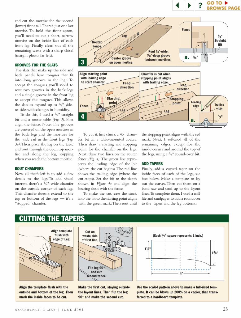
GROOVES FOR THE SLATSThe slats that make up the side andback panels have tongues that fitinto long grooves in the legs. Toaccept the tongues you’ll need torout two grooves in the back legsand a single groove in the front legto accept the tongues. This allowsthe slats to expand up to 1/8" side-to-side with changes in humidity.
To do this, I used a 1/4" straightbit and a router table (Fig. 3). Firstalign the fence. Note: The groovesare centered on the open mortises inthe back legs and the mortises forthe side rail in the front legs (Fig.3a).Then place the leg on the tableand rout through the open top mor-tise and along the leg, stoppingwhen you reach the bottom mortise.
ROUT CHAMFERSNow all that’s left is to add a fewdetails to the legs.To add visualinterest, there’s a 1/4"-wide chamferon the outside corner of each leg.This chamfer doesn’t extend to thetop or bottom of the legs — it’s a“stopped” chamfer.
To cut it, first chuck a 45° cham-fer bit in a table-mounted router.Then draw a starting and stoppingpoint for the chamfer on the legs.Next, draw two lines on the routerfence (Fig. 4). The green line repre-sents the leading edge of the bit(where the cut begins).The red lineshows the trailing edge (where thecut stops). Set the bit to the depthshown in Figure 4a and align thebearing flush with the fence.
To make the cut, ease the stockinto the bit so the starting point alignswith the green mark.Then rout until
the stopping point aligns with the redmark. Next, I softened all of theremaining edges, except for theinside corner and around the top ofthe legs, using a 1/8" round-over bit.
ADD TAPERSFinally, add a curved taper on theinside faces of each of the legs, seebox below. Make a template to layout the curves.Then cut them on aband saw and sand up to the layoutlines.To complete them, I used a millfile and sandpaper to add a roundoverto the tapers and the leg bottoms.
Trailingedge
Leadingedge
!/4"
&/16"
CL !/4"Straight
Bit
Fence
CUTTING THE TAPERS
3
4
Align the template flush with theoutside and bottom of the leg. Thenmark the inside faces to be cut.
Make the first cut, staying outsidethe layout lines. Then flip the leg90° and make the second cut.
Use the scaled pattern above to make a full-sized tem-plate. It can be blown up 200% on a copier, then trans-ferred to a hardboard template.
(Each 1/2" square represents 1 inch.)
a.
a.
H
Front Apron" x 2" x 16"#/4
Lower Back Rail1" x 4 " x 16"!/4
Upper Back Rail1" x 5 " x 16"!/16
Lower Side Rail1" x 4 " x 14 "!/4 %/8
Side Slat" x 4 " x 12 "%/8 !#/16 %/16
Side Starter Slatx 5 " x 12 "%/8" #/16 %/16
Back Starter Slat" x 5 " x 12 "%/8 !!/16 %/16
B
C
I
J
K
D
E
F
Front Rails" x 1 " x 16#/4 (/16
Back Slats" x 5 "
x 12 "%/8 %/16
%/16
UpperSide Rail1" x 5 "
x 14 "!/16
%/8
G
26 W O R K B E N C H ■■ M A Y | J U N E 2 0 0 1
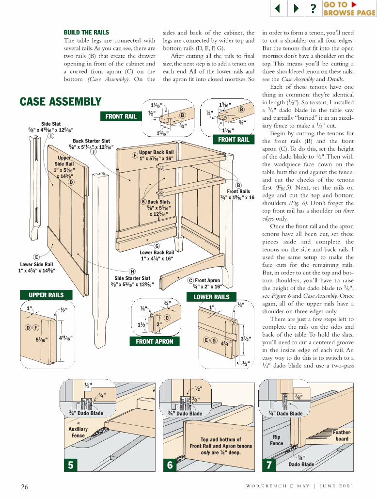
BUILD THE RAILSThe table legs are connected withseveral rails.As you can see, there aretwo rails (B) that create the draweropening in front of the cabinet anda curved front apron (C) on thebottom (Case Assembly). On the
sides and back of the cabinet, thelegs are connected by wider top andbottom rails (D, E, F, G).
After cutting all the rails to finalsize, the next step is to add a tenon oneach end. All of the lower rails andthe apron fit into closed mortises. So
in order to form a tenon, you’ll needto cut a shoulder on all four edges.But the tenons that fit into the openmortises don’t have a shoulder on thetop. This means you’ll be cutting athree-shouldered tenon on these rails,see the Case Assembly and Details.
Each of these tenons have onething in common: they’re identicalin length (1/2"). So to start, I installeda 3/4" dado blade in the table sawand partially “buried” it in an auxil-iary fence to make a 1/2" cut.
Begin by cutting the tenons forthe front rails (B) and the frontapron (C).To do this, set the heightof the dado blade to 1/4".Then withthe workpiece face down on thetable, butt the end against the fence,and cut the cheeks of the tenonsfirst (Fig.5). Next, set the rails onedge and cut the top and bottomshoulders (Fig. 6). Don’t forget thetop front rail has a shoulder on threeedges only.
Once the front rail and the aprontenons have all been cut, set thesepieces aside and complete thetenons on the side and back rails. Iused the same setup to make theface cuts for the remaining rails.But, in order to cut the top and bot-tom shoulders, you’ll have to raisethe height of the dado blade to 3/8",see Figure 6 and Case Assembly. Onceagain, all of the upper rails have ashoulder on three edges only.
There are just a few steps left tocomplete the rails on the sides andback of the table. To hold the slats,you’ll need to cut a centered groovein the inside edge of each rail. Aneasy way to do this is to switch to a1/4" dado blade and use a two-pass
AuxiliaryFence Rip
Fence
Feather-board
!/4"Dado Blade
CASE ASSEMBLY
Top and bottom ofFront Rail and Apron tenons
are " deep.only !/4
!/4"
#/4"
1 "(/16
1 "!/16
B
!/4"#/4"
C2"1 "!/2
!/2"
1 "(/16
1 "!/16
B
#/4"
E G 3 "!/2
!/2"
!/4"1"
4 "!/4
!/2"
D F
5 "!/16 4 "!!/16
1"
!/2"
!/4"
Dado Blade#/4"
!/2"
#/8"
Dado Blade#/4"
#/8"
Dado Blade!/4"
5 6 7
FRONT RAIL
FRONT RAIL
UPPER RAILS
FRONT APRON
LOWER RAILS

EdgeTongue
EndTongue
Side/BackSlat
H JStarter
Slat
I K
!/4"DadoBlade
#/8"
!/4"
!/4"DadoBlade
%/16"
#/16"
!/4"DadoBlade
#/8"
#/16"
V-GrooveBit
!/16"chamfer
45º
!/16"
27W O R K B E N C H ■■ M A Y | J U N E 2 0 0 1
RipFence
LowerSide Rail
E
8Front Apron
1 "#/8
Lay out curveusing scraphardboard.
SpringClamp
Hardboard
C
9
CHAMFER DETAILEDGE TONGUE DETAIL END TONGUE DETAILGROOVE DETAIL
SLAT ASSEMBLY
!/4"
Dado Blade#/4"
method to cut the groove. Start bysetting the rip fence so the blade isroughly centered on the thickness ofthe workpiece.Then after making asingle pass, turn the piece end forend and make a second pass to com-plete the groove (Fig. 7).
In addition to the grooves in theedge, you’ll need to cut a 3/4"-widegroove in the inside face of the lowerside and back rails. This holds thebottom shelf on three sides.
It’s a good idea to dry-assemblethe case to determine the locationof these grooves. The goal is tolocate them so the bottom edges ofthe grooves are even with the top ofthe apron (C). This will allow theshelf to sit flat on top of the apron.
Just one more note before youcut the grooves.The shelf will be asolid wood panel, so it will expandand contract with changes inhumidity.That means I had to allowfor the shelf to “move” front to back(across the grain). To allow for thiswood movement, I cut the groovein the back rail 1/8" deeper than thegrooves in the side rails (Fig. 8).
CUT THE ARCThe next step is to cut a gentle arcin the bottom of the front apron. Iused a thin scrap of hardboard and a
couple of spring clamps to lay outthe curve. Set the clamps at the endsof the arc and bend the scrap intothe desired location (Fig. 9). Thencut the arc with a band saw (or a jigsaw) and sand it smooth.
Finally, rout a 1/16" chamfer on thefront edge of the arc and on the out-side edges of the side and back rails.
ADD THE SLATSThe last step is to add the solidwood slats that make up the sideand back panels.The slats are madeof 5/8"-thick hardwood withtongue-and-groove joinery so theyslide together easily. Each side andback assembly has one starter slat (H,J) and two more slats (I, K). All ofthem have a tongue on the top andbottom that fits into the grooves inthe rails (Slat Assembly).
To determine the length of theslats, dry assemble the side (or back)and measure the distance between thegrooves. (My slats were 125/16" long.)
Another consideration is the widthof the slats. The starter slats are 3/8"wider than the others.That’s becausethey have a tongue on both longedges. One tongue fits into the longgroove in the legs, and the other fitsinto the groove in the adjacent slat.After cutting all the slats to size, it’s
time to cut the tongue and groovejoints. Start with the groove (GrooveDetail). Then cut tongues on theedges to fit (Edge Tongue Detail).
Before cutting the tongues in theends of the slats, nudge the rip fencecloser to the blade to cut a narrowertongue (End Tongue Detail). Finally, Irouted a 1/16" chamfer on all fouredges (Chamfer Detail).
Before going to the next step, Iapplied stain to the slats, includingthe tongues. (If the slats shrink, anyunstained tongues might be visible.)I used a mixture of three parts Zarcherry stain and one part WoodkoteJel’d cherry stain.
NOTE: Cut a 3/8"-deepgroove in Lower Back
Rail only.
NOTE: Slat sizesshown in CaseAssembly onPage 44.

Clamps holdShelf in place.
SHELF & TOPNow that most of the case is com-plete,work can begin on the shelf (L)and top (M).They’re very similar inthat each one is a glued-up, solidwood panel. Start by gluing up anoversized panel, then cut it to finalsize on the table saw, see Top/ShelfConstruction View. For more on cross-cutting wide blanks, see page 14.
Once the top and shelf are cut tofinished size, I routed a cove andchamfer around all four edges of thetop (Top Edge Detail), and a chamferon both edges of the shelf front(Shelf Edge Detail).At this point, youcan set the top aside and concen-trate on the shelf.
To complete the shelf, you’llneed to cut a notch in each cornerto fit around the legs (Notch Details).Notice that the notches in the frontare deeper than the ones in back.The reason for this is to create a gapwhere the shelf fits around the backlegs. When combined with thedeeper groove (cut earlier in theback rail), the gap allows room forthe shelf to expand (Gap Detail).
CASE ASSEMBLYNext, I put the case together in stages(Assembly Sequence). Start by gluing upthe two side assemblies (Step 1).
Once the glue dries, lay one ofthe sides on a workbench with theinside facing up. Now add the topand bottom rails for the back of thecase and slide in the slats.
28
NotchNotch
Top" x 18" x 20"#/4
M
Shelf" x 16" x 16 "#/4 %/8
L
TOP & SHELF CONSTRUCTION
ExpansionGap
G
L
C
L
overhang.!/8”
!/16"chamfer
ShelfRear Edge
!%/16"
!#/16"L
!/4” Cove
!/16" Chamfer
#/4”
M
ShelfFront Edge
!#/16"
1 "(/16
L
Starter Slat
Side Slat
D
E
H
I
Glue topedge only.
Front ApronC
ShelfLSTEP 1: Begin by gluing the Upper and
Lower Side Rails to the Legs to make theside panels. Then slide Starter Slat in first,followed by Side Slats.
STEP 2: Follow same procedure to install backpanel. Glue Front Rails and Apron into mortises andslide in Shelf, adding glue to top of Apron only.
STEP 3: To complete assembly, clampthe Shelf in place, install other side assem-bly, set the case upright, and add clamps.
ASSEMBLY SEQUENCE
W O R K B E N C H ■■ M A Y | J U N E 2 0 0 1
NOTE: Be sure tostain all Slats (including
tongues) before assembly.
TOP EDGE DETAIL
NOTCH DETAIL GAP DETAIL
SHELF EDGE DETAIL
NOTCH DETAIL
FIRST: Glue-up oversizepanel for the Top and Shelffrom 3/4"-thick hardwood.
SECOND: Cut panels tofinal size (see page 14).

Bin pull
Runner" x " x 14 "#/4 #/4 !#/16
Drawer Front" x 3 " x 14 "!/2 !/2 !%/16
Drawer Back" x 3 " x 14 "!/2 !/2 !%/16
Kicker" x " x 14 "#/4 #/4 !#/16
O
P
P
Drawer Sidex 3 " x 15 "!/2 !/2 %/16"
Stop
BackRail
Q
Drawer Bottom" ply. x 14 " x 14 "!/4 !%/16 #/8
R
Spacer" x 1 " x 13 "!/2 #/4 %/8
N
#8 x 1" FhWoodscrew
O
#8 x 1 "Fh Woodscrews
!/4
Top
!/4"-dia.elongatedshank hole
M
O
B
29W O R K B E N C H ■■ M A Y | J U N E 2 0 0 1
Next, glue in the front rails andthe apron (Step 2). But, beforeinstalling the shelf, I glued the topedge only of the apron and then slidthe shelf in place. Then I added acouple of clamps to hold it to theapron (Step 3). This way, the shelfexpands into the back groove. Note:The shelf should overlap the frontapron by an 1/8" (Shelf Edge Detail).
Finally, assemble the remainingside and set the case upright.You’llwant to measure diagonally acrossthe corners, making sure the case issquare.Then use bar clamps to holdeverything together.
Next,make two “L”-shaped guidesto hold the drawer in the opening.Each guide consists of a spacer (N)that centers the drawer and akicker/runner (O) to support it.
Take a look at the Drawer andGuide Assembly drawing for how theguides are oriented. Before installingthem in the table, you’ll need to drillshank holes in the spacer. I also drilledoversized shank holes in each kickerand the top front rail for the screwsused to attach the top (Top Assembly).Note: The two front holes in thekickers and rails are slightly elongatedto allow the top to expand in front.
DRAWER CONSTRUCTIONThe drawer is joined with dovetails,and it’s sized to allow 1/16" gap at thetop.To build the drawers, start by cut-ting the drawer front/back (P) andsides (Q) to size. Then these piecesare joined with 1/2" machine-cutdovetails, and a cherry plywood bot-tom (R) is added. For more on howto cut dovetails, refer to page 15.
Cut the groove for the drawerbottom on a table saw. Set the fenceso the blade is centered on the bot-tom socket of the front/back (P).This way it will be hidden by a pinon the drawer side (Q). Finally, glueup and assemble the drawer.
Once the drawer is complete,you’ll need to add a stop to the backrail. It ensures the drawer will beflush with the front rails when it’sclosed. The stop is a thin strip ofwood that’s sanded to thickness.Depending on your drawer, thethickness may vary, so be sure to testthe fit before gluing it in place.
After the stop was added, Istained the project with the cherrymixture I used on the slats.To pro-tect the wood from moisture, Iapplied three coats of an oil varnish.Finally, attach the bin pull (seePage 59). Center it on the drawerfront and screw it in place.
DRAWER & GUIDE ASSEMBLY
TOP ASSEMBLY
!/4"
Center pullon Drawer
Front.P
R
DRAWER DETAIL
NOTE: For tips on cutting half-blinddovetails, see page 15.
NOTE: Cut 1/4"-deep groove, cen-tered on socket.
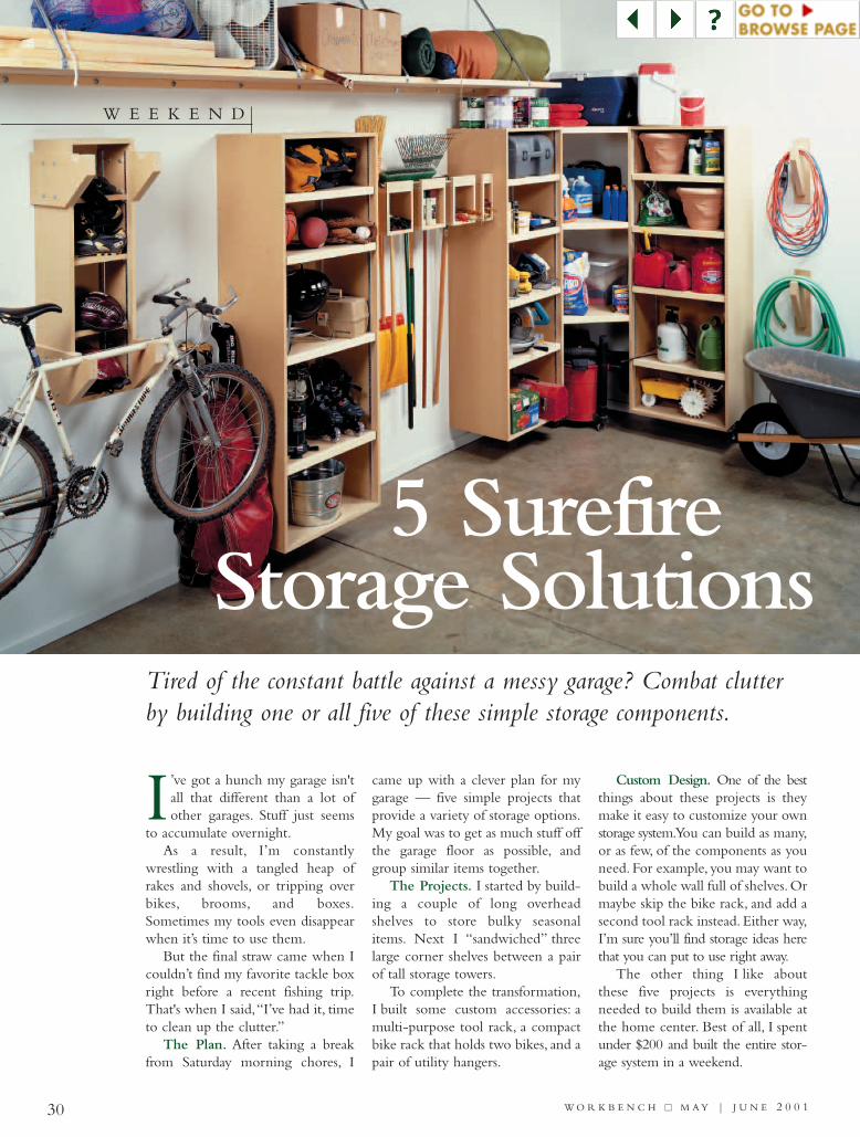
5 SurefireStorage Solutions
30 W O R K B E N C H ■■ M A Y | J U N E 2 0 0 1
’ve got a hunch my garage isn'tall that different than a lot ofother garages. Stuff just seems
to accumulate overnight.As a result, I’m constantly
wrestling with a tangled heap ofrakes and shovels, or tripping overbikes, brooms, and boxes.Sometimes my tools even disappearwhen it’s time to use them.
But the final straw came when Icouldn’t find my favorite tackle boxright before a recent fishing trip.That's when I said,“I’ve had it, timeto clean up the clutter.”
The Plan. After taking a breakfrom Saturday morning chores, I
came up with a clever plan for mygarage — five simple projects thatprovide a variety of storage options.My goal was to get as much stuff offthe garage floor as possible, andgroup similar items together.
The Projects. I started by build-ing a couple of long overheadshelves to store bulky seasonalitems. Next I “sandwiched” threelarge corner shelves between a pairof tall storage towers.
To complete the transformation,I built some custom accessories: amulti-purpose tool rack, a compactbike rack that holds two bikes, and apair of utility hangers.
Custom Design. One of the bestthings about these projects is theymake it easy to customize your ownstorage system.You can build as many,or as few, of the components as youneed. For example, you may want tobuild a whole wall full of shelves. Ormaybe skip the bike rack, and add asecond tool rack instead. Either way,I’m sure you’ll find storage ideas herethat you can put to use right away.
The other thing I like aboutthese five projects is everythingneeded to build them is available atthe home center. Best of all, I spentunder $200 and built the entire stor-age system in a weekend.
Tired of the constant battle against a messy garage? Combat clutterby building one or all five of these simple storage components.
I
W E E K E N D

CardboardFillFiller
Block
Shelf
Wall CleatWall Cleat #/8" x 4"
Lag Screw
#/8" x 2"Lag Screw
#/8" x 2" Lag Screw
1" O.D.Washer
1" O.D. Washer
1" O.D.Washer
Filler Block#8 x 2" FhSheet-Metal Screw
45 DegreeBend
Bracket( " Electrical
Conduit)!/2
Shelf18" x 80"
A
B
C
31W O R K B E N C H ■■ M A Y | J U N E 2 0 0 1
It's hard to imagine a quicker way toadd a shelving system than longshelves mounted high on the wall.They’re perfect for storing light-weight, bulky items (150 lbs. max.),and they take advantage of spacethat usually goes to waste.
DOORS DO DOUBLE-DUTYThe unusual thing about theseshelves is they’re made from hol-low-core interior doors. (I used36"-wide doors.) They make per-fect shelves because they’re flat,smooth, and inexpensive.
Note: Hollow-core doors areavailable at most home centers forabout $20, or you might find a bar-gain in the “scratch and dent” bin.
Each door makes two shelves (A).This is just a matter of ripping thedoor 18" wide using a straightedgeand circular saw equipped with a ply-wood blade, as shown in Figure 1.Toprevent the thin “skin” of the doorfrom splintering, I taped the cutline.
The only problem is there’snothing to support the veneer alongthe cut line. To prevent the thin
veneer from breaking, I added afiller block (B).This is a piece of 2xstock ripped to width to fit into theopening. (In my case, 11/8" wide.)
MOUNTING THE SHELFAfter gluing the filler block, you’reready to mount the shelf.The backedge is screwed to a wood cleat (C)attached to the wall with 4" lagscrews, see Cleat Detail. I wantedplenty of holding power so I used lagscrews to hang all of the projects.
To support the front edge of theshelf, I used two brackets.These area bit unusual. They’re made of 1/2"
electrical (EMT) conduit.To createthe flat, angled ends that attach tothe wall and the front of the shelf,simply crimp and bend the conduitin a vise.
PROJECT1 overhead shelf
CLEAT DETAIL
Shelf Lag Screw
Bracket( " Electrical
Conduit)!/2
Screw lag screwinto wall stud.
Hollow-CoreDoor
Shelf
Tape cut line.
Straightedge
#/4" Scrap Plywoodprovides support.1
MATERIALS LIST (FOR 2 SHELVES)
LUMBERA (2) Shelves (H-C Door) 18" wide x 80" longB (2) Filler Blocks 11/2" x 11/8" x approx. 78"C (2) Wall Cleats 11/2" x 1" x approx. 80"
HARDWARE (10)3/8" x 4" Lag Screws w/Washers(8) 3/8" x 2" Lag Screws w/Washers(12)#8 x 2" Fh Sheet-Metal Screws1/2" Electrical Conduit (approx. 10 ft.)

PROJECT2 storage tower
A
A
Side
#8 x 2" FhSheet-Metal
Screw
#/8" x 4"Lag Screw
1" O.D.Washer
Bottom
Shelf
ShelfEdging
72" ShelfStandard
Back
Top
B
C
C
D
E
E
32 W O R K B E N C H ■■ M A Y | J U N E 2 0 0 1
These tall storage towers haveadjustable shelves that provideplenty of storage.You can build twotowers and use them to support thecorner shelves, as shown on thenext page. Or by mounting twotowers along the same wall, you canadd the multi-purpose tool rackbetween them (see page 34).
BUILD A BASIC BOXEach tower is an open-front boxmade of 3/4" Medium-DensityFiberboard. (You could also use ply-wood.) I paid about $40 for two49" × 97" sheets of MDF (enoughto build one tower).
Start by cutting the sides (A) andback (B) of the tower following thedimensions shown. Again, I recom-mend a circular saw and straightedgefor accuracy.The top and bottom (C)of the tower are 3/4" narrower thanthe sides to leave room for the back.
The tower is screwed togetherwith sheet-metal screws. Thestraight shank of a sheet-metalscrew isn’t as likely to split the MDFas a standard woodscrew with atapered shank. Even so, it’s still agood idea to drill pilot holes.
ADD THE SHELVESOnce the basic box is complete, it’stime to add the adjustable shelves(D). Each tower has four shelvesthat rest on clips installed in a pairof shelf standards on each side.
Two strips of wood edging (E)on each shelf keep it from sagging.After ripping 11/2"-wide strips, justglue the edging in place.
MOUNTING THE TOWERSTo prevent moisture from damagingthe towers, I mounted them about 6"off the floor.This also gave me roomto clean underneath.
The towers weigh a ton (MDF isquite heavy), so you’ll need somehelp supporting them. They’remounted on the wall with lag screwsdriven into wall studs.
Note: If you plan on building thecorner shelves on the next page,mount them to the wall before youinstall the towers.
MATERIALS LIST (FOR 1 TOWER)
LUMBER & SHEET MATERIALA (2) Sides 3/4" x 18" x 74"B (1) Back 3/4" x 251/2" x 74"C (1) Top/Bottom 3/4" x 171/4" x 251/2"D (4) Shelves 3/4" x 151/2" x 25"E (8) Shelf Edging 3/4" x 11/2" x 25"
HARDWARE (4) 3/8" x 4" Lag Screws w/Washers(38)#8 x 2" Fh Sheet-Metal Screws (4) 5/8" x 3/16" x 72" Shelf Standards
w/Screws (16)Shelf Clips
NOTE: Drill pilotholes to avoidsplitting the MDF.
SHORT TOWER OPTION
Instead ofone tall tower,
build two shorter ones.

Side Cleat
RightCorner Cleat
StorageTower
StorageTower
LeftCorner Cleat
#/8" x 4"Lag Screw
1" O.D.Washer
#8 x 1 " FhSheet-Metal
Screw
!/4
#8 x 1 " FhSheet-Metal
Screw
!/4
ShelfA
BB
CD
EShelf
Edging
Nail Edgingin place.
PROJECT3 corner shelves
33W O R K B E N C H ■■ M A Y | J U N E 2 0 0 1
LUMBER & SHEET MATERIALA (1) Shelf 3/4" x 303/4" x 303/4"B (2) Side Cleats 3/4" x 11/2" x 17"C (1) Right Corner Cleat 3/4" x 11/2" x 30"D (1) Left Corner Cleat 3/4" x 11/2" x 291/4"E (1) Shelf Edging 3/4" x 11/2" x 191/2"
HARDWARE (4) 3/8" x 4" Lag Screws w/Washers(18)#8 x 11/4" Fh Sheet-Metal Screws
The corners of my garage don’t getused much, except for junk. But byadding three large shelves supportedby one of the storage towers oneach side, I was able to use thatwasted corner for additional storage.And I didn’t take up a lot of floor orwall space, either.
CORNER SHELF STORAGEAs you can see in the drawingabove, each shelf (A) starts out as asquare piece of 3/4" MDF that’ssized to fit flush with the front edgeof the towers. To prevent the sharpoutside corner of the shelf fromsticking out in front of the towers,it’s cut at an angle. A circular sawmakes quick work of trimming offthe waste.
Each shelf is supported by fourwood cleats.A pair of side cleats (B)are attached to the towers, and twocorner cleats (C and D) mount tothe wall. Note: Cut the left cornercleat (D) 3/4" shorter than the rightcleat (C).All four cleats are screwedto the bottom of the shelf.
As with the tower shelves, a stripof wood edging (E) helpsstrengthen the front, unsupported
edge of each shelf. After miteringthe edging to length, I glued it tothe shelf and tacked in a few nails to“clamp” it in place.
MOUNTING SEQUENCENow you’re ready to mount theshelf to the wall and towers.
Shelves First. Start by attachingeach shelf to the wall with a pair oflag screws through both cornercleats (C and D). I found it workedbest to position the top shelf so itwould fit flush with the tops of thetowers.This gave me a long, contin-uous storage space.
The spacing between theremaining shelves is up to you. I leftroom underneath the bottom shelfto store my shop vacuum. But if youdon’t need that space, you canalways add a fourth shelf flush withthe bottom of the towers.
Towers Next. Now that theshelf is secured to the wall, go aheadand fit the towers flush with theshelf. To hold the towers and shelfsnug, drive a couple of screwsthrough each side cleat (B) into theside of the tower. Don’t forget tosecure the towers to the wall, too.
30 "#/4
30 "#/4
18"
18"
#/4 !/2" x 1 "Shelf Edging
Right Corner Cleat1 " x 30"!/2
LeftCorner Cleat1 " x 29 "!/2 !/4
Side Cleat1 " x 17"!/2
Side Cleat1 " x 17"!/2
18"
CLEAT DETAILS
MATERIALS LIST(FOR 1 SHELF)
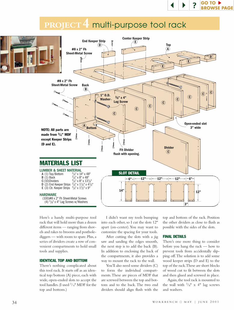
PROJECT4 multi-purpose tool rack
34 W O R K B E N C H ■■ M A Y | J U N E 2 0 0 1
MATERIALS LISTLUMBER & SHEET MATERIAL
A (1) Top/Bottom 3/4" x 14" x 48"B (1) Back 3/4" x 8" x 48"C (10)Dividers 3/4" x 8" x 131/4"D (2) End Keeper Strips 3/4" x 11/2" x 41/2"E (3) Ctr. Keeper Strips 3/4" x 11/2" x 9"
HARDWARE (100)#8 x 2" Fh Sheet-Metal Screws
(4) 3/8" x 4" Lag Screws w/Washers
Bottom
Fit Dividerflush with opening.
Open-ended slot3" wide
Divider
Top
Back
End Keeper Strip
#8 x 2" FhSheet-Metal Screw
#8 x 2" FhSheet-Metal Screw
Center Keeper Strip
A
A
B
C
CC
CC
CC
C C
D
D
E
E
E
#/8" x 4"Lag Screw
1" O.D.Washer
NOTE: All parts aremade from 3/4” MDFexcept Keeper Strips(D and E).
Here’s a handy multi-purpose toolrack that will hold more than a dozendifferent items — ranging from shov-els and rakes to brooms and posthole-diggers — with room to spare. Plus, aseries of dividers create a row of con-venient compartments to hold smalltools and supplies.
IDENTICAL TOP AND BOTTOMThere’s nothing complicated aboutthis tool rack. It starts off as an iden-tical top/bottom (A) piece, each withwide, open-ended slots to accept thetool handles. (I used 3/4" MDF for thetop and bottom.)
I didn’t want my tools bumpinginto each other, so I cut the slots 12"apart (on-center).You may want tocustomize the spacing for your tools.
After cutting the slots with a jigsaw and sanding the edges smooth,the next step is to add the back (B).In addition to enclosing the back ofthe compartments, it also provides away to mount the rack to the wall.
You’ll also need some dividers (C)to form the individual compart-ments.These are pieces of MDF thatare screwed between the top and bot-tom and to the back. The two enddividers should align flush with the
top and bottom of the rack. Positionthe other dividers as close to flush aspossible with the sides of the slots.
FINAL DETAILSThere’s one more thing to considerbefore you hang the rack — how toprevent tools from accidentally slip-ping off.The solution is to add somewood keeper strips (D and E) to thetop of the rack.These are short blocksof wood cut to fit between the slotsand then glued and screwed in place.
Again, the tool rack is mounted tothe wall with 3/8" x 4" lag screwsand washers.
6"
14" 12"
3"
6"12"12"12"
SLOT DETAIL
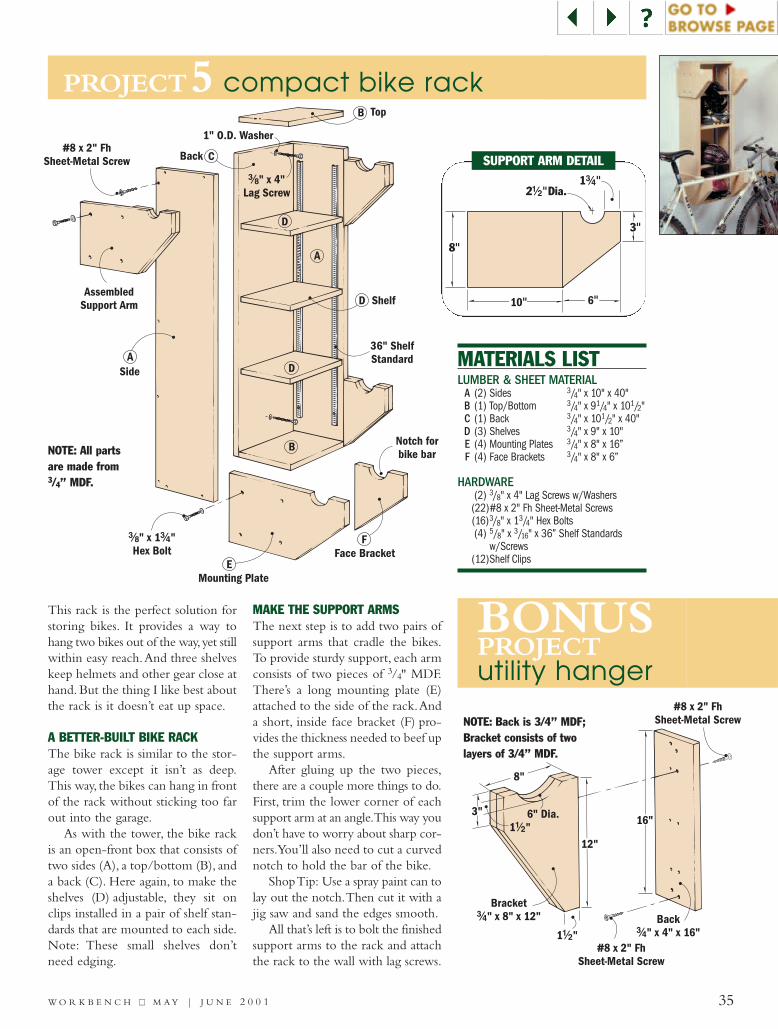
PROJECT5 compact bike rack
35W O R K B E N C H ■■ M A Y | J U N E 2 0 0 1
LUMBER & SHEET MATERIALA (2) Sides 3/4" x 10" x 40"B (1) Top/Bottom 3/4" x 91/4" x 101/2"C (1) Back 3/4" x 101/2" x 40"D (3) Shelves 3/4" x 9" x 10"E (4) Mounting Plates 3/4" x 8" x 16”F (4) Face Brackets 3/4" x 8" x 6”
HARDWARE (2) 3/8" x 4" Lag Screws w/Washers(22)#8 x 2" Fh Sheet-Metal Screws(16)3/8" x 13/4" Hex Bolts(4) 5/8" x 3/16" x 36” Shelf Standards
w/Screws(12)Shelf Clips
This rack is the perfect solution forstoring bikes. It provides a way tohang two bikes out of the way,yet stillwithin easy reach.And three shelveskeep helmets and other gear close athand. But the thing I like best aboutthe rack is it doesn’t eat up space.
A BETTER-BUILT BIKE RACKThe bike rack is similar to the stor-age tower except it isn’t as deep.This way, the bikes can hang in frontof the rack without sticking too farout into the garage.
As with the tower, the bike rackis an open-front box that consists oftwo sides (A), a top/bottom (B), anda back (C). Here again, to make theshelves (D) adjustable, they sit onclips installed in a pair of shelf stan-dards that are mounted to each side.Note: These small shelves don’tneed edging.
MAKE THE SUPPORT ARMSThe next step is to add two pairs ofsupport arms that cradle the bikes.To provide sturdy support, each armconsists of two pieces of 3/4" MDF.There’s a long mounting plate (E)attached to the side of the rack.Anda short, inside face bracket (F) pro-vides the thickness needed to beef upthe support arms.
After gluing up the two pieces,there are a couple more things to do.First, trim the lower corner of eachsupport arm at an angle.This way youdon’t have to worry about sharp cor-ners.You’ll also need to cut a curvednotch to hold the bar of the bike.
Shop Tip: Use a spray paint can tolay out the notch.Then cut it with ajig saw and sand the edges smooth.
All that’s left is to bolt the finishedsupport arms to the rack and attachthe rack to the wall with lag screws.
MATERIALS LIST
2 Dia.!/2”1#/4”
3”
8”
6”10”
SUPPORT ARM DETAIL
Side
AssembledSupport Arm
#/8 #/4" x 1 "Hex Bolt
#8 x 2" FhSheet-Metal Screw
Mounting Plate
Face Bracket
Top
Shelf
Notch forbike bar
36" ShelfStandard
#/8" x 4"Lag Screw
1" O.D. Washer
Back
A
A
B
B
C
D
D
D
E
F
BONUSPROJECTutility hanger
Back" x 4" x 16"#/4
#8 x 2" FhSheet-Metal Screw
#8 x 2" FhSheet-Metal Screw
Bracket" x 8" x 12"#/4
1 "!/2
1 "!/2
12"
8"
16"6" Dia.3"
NOTE: Back is 3/4” MDF;Bracket consists of twolayers of 3/4” MDF.
NOTE: All partsare made from3/4” MDF.
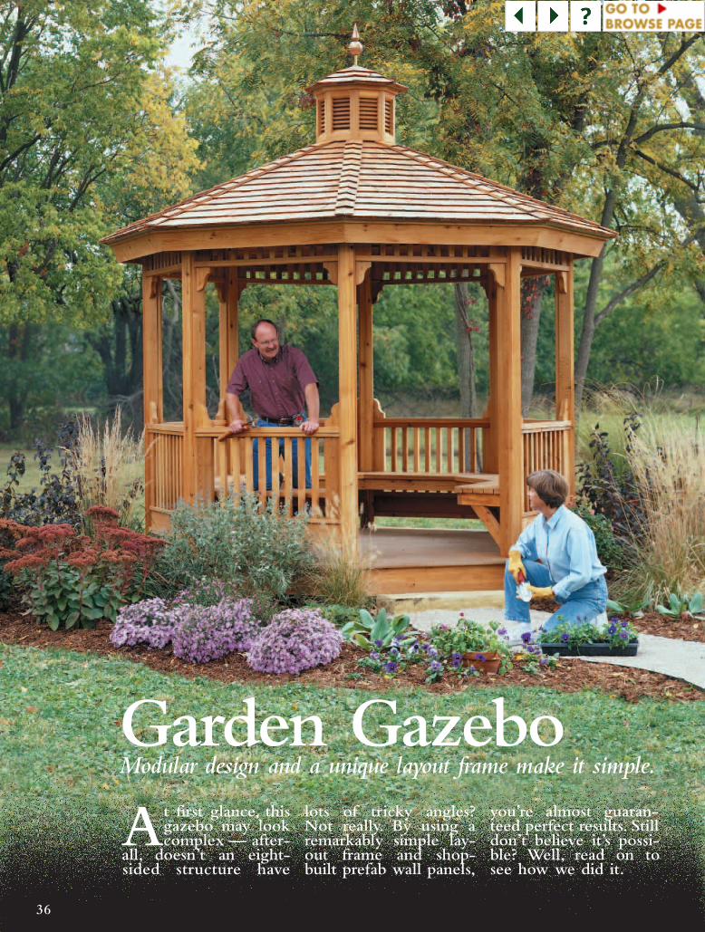
Modular design and a unique layout frame make it simple.
36
Garden GazeboAt first glance, this
gazebo may lookcomplex — after-
all, doesn’t an eight-sided structure have
lots of tricky angles?Not really. By using aremarkably simple lay-out frame and shop-built prefab wall panels,
you’re almost guaran-teed perfect results. Stilldon’t believe it’s possi-ble? Well, read on tosee how we did it.

CedarFascia Board
Cupola(See page 50)
Built-InBenches
(Seepage 53)
Cedar Trim
Cedar SkirtBoard
Maintenance-free deckingeliminates splinters and rot
(See page 41).Modular units lets you preassemblewall panels, then erect them on site.
RailAssembly
LintelAssembly
RafterSystem
(See page 46)
CedarTrim Strip
Check out our tip on page 52for gluing-up eight pie-shaped pieces.
Finial(See page 54)
Louvered Panels on eight-sidedCupola provide ventilation.
Sheathing
Learn about different grades ofcedar shingles and how toinstall them on page 49.
CedarCap Shingles
37
GAZEBO ASSEMBLY VIEWOVERALL GAZEBO SIZE:11 FT. 2 IN. WIDE (AT WIDEST POINT) x 11 FT. TALL(NOT INCLUDING CUPOLA & FINIAL)
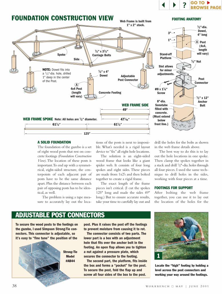
Concrete Footing
AdjustablePost Connector
!/2" x 4"Dowel
4x4 Post(length
will vary)
SpokeSide
!/2 !/2" x 3 "Carriage Bolts
Web Frame is built from1" x 2" stock.
A
38 W O R K B E N C H ■■ M A Y | J U N E 2 0 0 1
FOUNDATION CONSTRUCTION VIEW
Note: All holes are " diameter.!/2
61!/2"
125"
61!/2"
49"
47!/16"
PostConnector
!/2" x 12"Anchor
Bolt
!/2" Nut
Stand-offPlatform
8"-dia.Sonotubefilled withconcrete.
(Must extendbelow
frost line.)
Slot allowsfor minor
adjustments.
#8 x 1 "Screw
!/4
Post(4x4,length
will vary)
1"
3"
!/2"-dia.Dowel,4" long
A
FOOTING ANATOMY
WEB FRAME SPOKE
WEB FRAME SIDE
1Locate the “high” footing by holding alevel across the post connectors andworking your way around the footings.
ADJUSTABLE POST CONNECTORS To secure the wood posts to the footings onthe gazebo, I used Simpson Strong-Tie con-nectors. This connector is adjustable, soit’s easy to “fine tune” the position of the
post. Plus it raises the post off the footingsto prevent moisture from causing it to rot.
The connector consists of two parts. Thelower part is a box with an adjustmenthole that fits over the anchor bolt in thefooting. An open flap allows you to tightena nut against a pressure plate, whichsecures the connector to the footing.
The second part, the platform, fits insidethe box and forms a “pocket” for the post.To secure the post, fold the flap up andscrew all four sides of the box to the post.
Strong-TieModel#AB44
A SOLID FOUNDATIONThe foundation of the gazebo is a setof eight wood posts that rest on con-crete footings (Foundation ConstructionView). The location of these posts isimportant.To end up with a symmet-rical, eight-sided structure, the cen-terpoints of each adjacent pair ofposts have to be the same distanceapart. Plus the distance between eachpair of opposing posts has to be iden-tical, as well.
The problem is using a tape mea-sure to accurately lay out the loca-
tions of the posts is next to impossi-ble. What’s needed is a rigid layoutdevice to “fix”all eight hole locations.
The solution is an eight-sidedwood frame that looks like a giantspider web. It consists of four longspokes and eight sides. These piecesare made from 1x2’s and then boltedtogether to create a rigid frame.
The exact length of the framepieces isn’t critical. (I cut the spokes125" long and made the sides 49"long.) But to ensure accurate results,take your time to carefully lay out and
drill the holes for the bolts as shownin the web frame details above.
The best way to do this is to layout the hole locations in one spoke.Then clamp the spokes together ina stack and drill 1/2"-dia.holes throughall four pieces. I used the same tech-nique to drill holes in the sides,working with four pieces at a time.
FOOTINGS FOR SUPPORTAfter bolting the web frametogether, you can use it to lay outthe location of the holes for the
NOTE: Dowel fits intoa 1/2"-dia. hole, drilled 1" deep in the centerof the Post.

39W O R K B E N C H ■■ M A Y | J U N E 2 0 0 1
FINDING LEVEL ON SLOPING GROUND
FIRST: Locate highest footing and cut post 11 " long.!/2
11!/2"SECOND: Transfer level line to"downhill" post.
HighestFooting
Downhill Post
2 3 4Now set a post in the connector on thehigh footing, mark the height of thefloor joists, and cut the post to length.
To mark the next post, set a level ontop of the first post and mark a levelline. Work from post to post.
Use the web frame to position the postsand connectors. The frame fits on dow-els centered in the top of each post.
concrete footings.To do this, set theframe where you plan to build thegazebo. Then press down to markthe ground with the bolts.
Now it’s just a matter of diggingthe holes for the footings. To avoidfrost heave, I dug 42"-deep holes.You’ll want to check with yourlocal building inspector for theproper depth in your area.
The footings extend above theground (grade) about 2" to 3",so you’llneed a form to contain the concrete(Footing Anatomy). I used 8"-dia. card-board cylinders called Sonotubes.(They’re available at most home cen-ters.) These tubes are set into the holeand filled with concrete.
While the concrete is still wet,insert an L-shaped anchor bolt ineach footing.These bolts are used tosecure the connectors that hold theposts (see the box on page 38).
The goal is to center the anchorbolts on the footings. Here again, theweb frame comes in handy. Justremove the bolts connecting the sidesof the frame (one at a time) and fitthe holes over the anchor bolts.Thenleave the frame in place for two tothree days until the concrete cures.
ANCHOR THE POSTSNow you can concentrate on theposts. I used 4x4 posts made frompressure-treated southern pine andcut them to rough length (will vary).
The metal post connectorssecure the posts to the footings. Boltthese connectors loosely in place fornow.You’ll probably need to make
some minor adjustments later.When installing the posts, the idea isto start with the highest footing.You’ll need to “eyeball” the highestfooting and check it with a level, asshown in Figure 1.
Once you find the high footing,insert a post and mark the desiredheight for the floor joists of thegazebo (Fig. 2). This was 111/2" inmy case.Then remove the post andcut it to final length.
After reinstalling the post, secureit to three sides of the metal bracketwith screws. (Leave the flap on thefourth side open to provide accessto the nut on the anchor bolt.)
Once the first post is in place,temporarily install the rest of theposts.Then, to allow for differencesin the slope of the ground at each
footing, transfer a level line frompost to post, as shown above and inFigure 3. Now remove the posts, cutthem to length, and secure them tothe connectors. Shop Tip: Be sureto label the posts so you can putthem back in the right place.
It may be necessary to tweak thelocation of the posts. (Remember,the distance between the center-points must be identical.) The webframe makes this a simple task. Justdrill a centered hole in the top ofeach post, insert a dowel, and placethe frame over the dowels (Fig. 4).
Once the frame is in place, makesure the inside face of each post issquare to the center of the frame.Then tighten the nut on eachanchor bolt, bend up the tab, andscrew it to the post.
It’s a pretty safe bet that the slope of the ground will vary from onefooting to another. To compensate for this, the foundation of thegazebo is leveled by varying the length of the wood posts. The idea is tocut the post on the highest footing to final length (111/2"), then use alevel to transfer the proper elevation to the “downhill” posts.
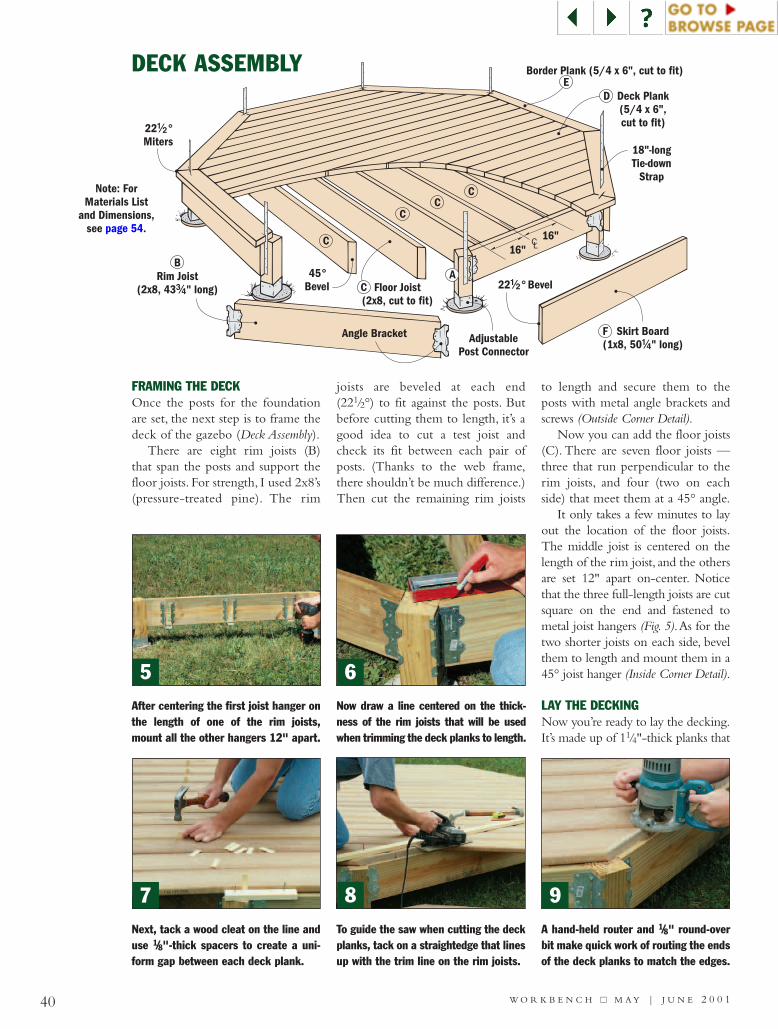
22 °Miters
!/2
D Deck Plank(5/4 x 6",cut to fit)
22 ° Bevel!/2Rim Joist
(2x8, 43 " long)#/4
B
Floor Joist(2x8, cut to fit)
Border Plank (5/4 x 6", cut to fit)
Skirt Board(1x8, 50 " long)!/4
F
C
45°Bevel
CC
C
Angle Bracket AdjustablePost Connector
18"-longTie-down
StrapNote: For
Materials Listand Dimensions,
see page 54.
CA
E
CL16"16"
DECK ASSEMBLY
5 6
7 8 9
FRAMING THE DECKOnce the posts for the foundationare set, the next step is to frame thedeck of the gazebo (Deck Assembly).
There are eight rim joists (B)that span the posts and support thefloor joists. For strength, I used 2x8’s(pressure-treated pine). The rim
joists are beveled at each end(221/2°) to fit against the posts. Butbefore cutting them to length, it’s agood idea to cut a test joist andcheck its fit between each pair ofposts. (Thanks to the web frame,there shouldn’t be much difference.)Then cut the remaining rim joists
to length and secure them to theposts with metal angle brackets andscrews (Outside Corner Detail).
Now you can add the floor joists(C). There are seven floor joists —three that run perpendicular to therim joists, and four (two on eachside) that meet them at a 45° angle.
It only takes a few minutes to layout the location of the floor joists.The middle joist is centered on thelength of the rim joist, and the othersare set 12" apart on-center. Noticethat the three full-length joists are cutsquare on the end and fastened tometal joist hangers (Fig. 5).As for thetwo shorter joists on each side, bevelthem to length and mount them in a45° joist hanger (Inside Corner Detail).
LAY THE DECKINGNow you’re ready to lay the decking.It’s made up of 11/4"-thick planks that
After centering the first joist hanger onthe length of one of the rim joists,mount all the other hangers 12" apart.
A hand-held router and 1/8" round-overbit make quick work of routing the endsof the deck planks to match the edges.
Now draw a line centered on the thick-ness of the rim joists that will be usedwhen trimming the deck planks to length.
Next, tack a wood cleat on the line anduse 1/8"-thick spacers to create a uni-form gap between each deck plank.
To guide the saw when cutting the deckplanks, tack on a straightedge that linesup with the trim line on the rim joists.
40 W O R K B E N C H ■■ M A Y | J U N E 2 0 0 1
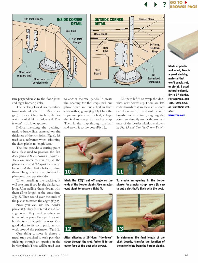
10 11
12 13
Made of plasticand wood, Trex isa great deckingmaterial thatwon’t crack, rot,or shrink. I usednatural-colored,5/4 x 6" planks.For sources, call(800) 289-8739or visit their web-site:www.trex.com
run perpendicular to the floor joistsand eight border planks.
The decking I used is a manufac-tured material called Trex. (See mar-gin.) It doesn’t have to be sealed orwaterproofed like solid wood. Plusit won’t shrink or splinter.
Before installing the decking,mark a heavy line centered on thethickness of the rim joists (Fig. 6). It’sused as a reference when trimmingthe deck planks to length later.
The line provides a starting pointfor a cleat used to position the firstdeck plank (D), as shown in Figure 7.To allow water to run off, all theplanks are spaced 1/8" apart.Be sure tolay out all the planks before nailingthem.The goal is to have a full-widthplank on two opposite sides.
When installing the decking, itwill save time if you let the planks runlong. After nailing them down, trimthem all to length at the same time(Fig. 8).Then round over the ends ofthe planks to match the edges (Fig. 9).
Now you can add the borderplanks (E).They’re mitered at a 221/2°angle where they meet over the cen-terline of the posts.Each plank shouldbe identical in length. Even so, it’s agood idea to fit each plank as youwork around the perimeter (Fig. 10).
One thing to note is there’s ametal strap attached to each post thatsticks up through an opening in theborder planks.These will be used later
to anchor the wall panels. To createthe opening for the straps, nail oneplank down and cut a kerf in bothends with a jig saw (Fig.11).Once theadjoining plank is attached, enlargethe kerf to accept the anchor strap.Then fit the strap through the kerfand screw it to the post (Fig. 12).
All that’s left is to wrap the deckwith skirt boards (F).These are 1x8cedar boards that are beveled at eachend. Here again, fit and nail the skirtboards one at a time, aligning thejoint line directly under the miteredends of the border planks, as shownin Fig. 13 and Outside Corner Detail.
Mark the 221/2° cut off angle on theends of the border planks. Use an adja-cent plank to ensure a tight fit.
To create an opening in the borderplanks for a metal strap, use a jig sawto cut a slot that’s flush with the post.
To determine the final length of theskirt boards, transfer the location ofthe miter joints from the border planks.
After slipping a 18"-long “tie-down”strap through the slot, fasten it to theouter face of the post with screws.
90° Joist Hanger
Rim Joist
Floor Joist(square end)
Floor Joist(beveled end)
45° JoistHanger
Deck Plank
Border Plank
SkirtBoard
RimJoist
24"-longTie-down
Strap
6dGalvanizedFinish Nail
INSIDE CORNERDETAIL
OUTSIDE CORNERDETAIL
41W O R K B E N C H ■■ M A Y | J U N E 2 0 0 1

42 W O R K B E N C H ■■ M A Y | J U N E 2 0 0 1
WALL PANEL ASSEMBLY
14 15
PREFAB THE WALLSTo simplify the construction of thegazebo, it’s designed with identicalwall panels. This speeds things upconsiderably because it allows you tomake all the “like” parts of each wallpanel using the same tool setups.Also,you can assemble the panels in the
comfort of your shop and then erectthe “prefab” walls as weather permits.
The wall panels have two mainsections: a lower rail assembly and anupper lintel assembly that are con-nected by a pair of tall side posts (WallPanel Assembly).Altogether,you’ll needseven rail assemblies and eight lintel
assemblies. (There isn’t a rail assemblyat the entrance of the gazebo.) Note:I used cedar for the wall panelsbecause it’s resistant to rot and decay.
MAKING THE RAILSEach wall panel is made up of severaldifferent rails (G, H, I, and J). So takea minute to familiarize yourself withthem before cutting any lumber.
If you look at the lower rail assem-bly, you’ll see there are two drip rails(G, H) that capture a row of balustersbetween them. A couple of cap rails(I) form the top and bottom of thisrail assembly.
As for the lintel assembly, it’s muchsimpler.The balusters fit between anupper and lower rail (J).
The final width of these rails willvary. But to get into a “productionmode,” I started by ripping enoughstock for all the rails to a width of 3".
Before cutting the rails to length,notice that there’s a 221/2° miter ateach end.As a result, the tall side posts(which are attached to the rails) sit ata corresponding angle.When the wallpanels are installed later, this producesthe octagonal shape of the walls.
One thing to be aware of here isthe length of the rails.The cap and lin-tel rails (I, J) are slightly longer thanthe drip rails (G, H).
With that in mind, tilt the head ofthe miter gauge on your table saw221/2°, as shown in Figure 14. (Or, usea power miter saw instead.) Thenmiter all the rails to final length.
At this point, the cap rails (I) arecomplete, so set them aside. But theremaining rails still need some work.
To see what I mean, take a look atthe Wall Panel Assembly again and alsoDetail ‘a’. Notice that the balusters inthe lintel assembly fit into grooves inthe upper and lower rails (J). A dadoblade mounted in the table sawmakes quick work of cutting thesegrooves (Fig. 15).
You’ll also need to cut an identicalgroove in the lower drip rail only(Detail ‘c’). This groove fits over astretcher that’s added later.
With the groove complete, thenext step is to rip the drip rails towidth.This is pretty straightforward
Miter both ends of the 2x4 rail blanksat 221/2°. Eventually, this will allow thewall panels to form an octagon.
To accept the balusters in the lintel(and to fit over the stretcher), cut acentered groove in rails (H) and (J).
a.a.
b.
c.
Note: Wall assemblysequence is shown
on page 44.
Note: All pieces aremade from 2x cedar.
For dimensions,turn to page 54.
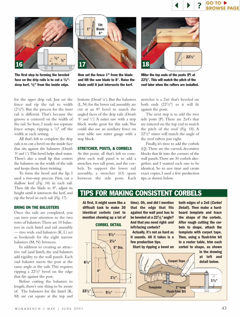
43W O R K B E N C H ■■ M A Y | J U N E 2 0 0 1
16 17 18The first step to forming the beveledface on the drip rails is to cut a 1/4"-deep kerf, 1/2" from the inside edge.
Now set the fence 1" from the bladeand tilt the saw blade to 8°. Raise theblade until it just intersects the kerf.
Miter the top ends of the posts (P) at221/2°. This will match the pitch of theroof later when the rafters are installed.
for the upper drip rail. Just set thefence and rip the rail to width(21/2"). But the process for the lowerrail is different. That’s because thegroove is centered on the width ofthe rail. So here, I made two separatefence setups, ripping a 1/4" off thewidth at each setting.
All that’s left to complete the driprails is to cut a bevel on the inside facethat sits against the balusters (Details‘b’ and ‘c’).This bevel helps shed water.There’s also a small lip that centersthe balusters on the width of the railsand keeps them from twisting.
To form the bevel and the lip, Iused a two-step process. First, cut ashallow kerf (Fig. 16) in each rail.Then tilt the blade to 8°, adjust itsheight until it intersects the kerf, andrip the bevel in each rail (Fig. 17).
BRING ON THE BALUSTERSOnce the rails are completed, youcan turn your attention to the tworows of balusters.There are 10 balus-ters in each lintel and rail assembly— two wide end balusters (K, L) actas bookends for the eight narrowbalusters (M, N) between.
In addition to creating an attrac-tive rail (and lintel), the end balustersadd rigidity to the wall panels. Eachend baluster meets the post at thesame angle as the rails.This requiresripping a 221/2° bevel on the edgethat fits against the post.
Before cutting the balusters tolength, there’s one thing to be awareof. The balusters for the lintel (K,M) are cut square at the top and
bottom (Detail ‘a’). But the balusters(L, N) for the lower rail assembly arecut at an 8° bevel to match theangled faces of the drip rails (Details‘b’ and ‘c’). A miter saw with a stopblock works great for this task. Youcould also use an auxiliary fence onyour table saw miter gauge with astop block.
STRETCHER, POSTS, & CORBELSAt this point, all that’s left to com-plete each wall panel is to add astretcher, two tall posts, and the cor-bels. To support the lower railassembly, a stretcher (O) spansbetween the side posts. Each
stretcher is a 2x6 that’s beveled onboth ends (221/2°) so it will fitagainst the posts.
The next step is to add the twoside posts (P). These are 2x4’s thatare mitered on the top end to matchthe pitch of the roof (Fig. 18). A221/2° miter will match the angle ofthe roof rafters just right.
Finally, it’s time to add the corbels(Q).These are the curved, decorativeblocks that fit into the corners of thewall panels.There are 30 corbels alto-gether, and I wanted each one to beidentical. So to save time and createexact copies, I used a few productiontips, as shown below.
TIPS FOR MAKING CONSISTENT CORBELS
2"-longFlush-Trim Bit
Carpet Tape
Template
At first, it might seem like adifficult task to make 30identical corbels (not tomention chewing up a lot of
time). Oh, and did I mentionthat the edge that fitsagainst the wall post has tobe beveled at a 221/2° angle?And that you need right- andleft-facing corbels?Actually, it’s not as hard as
it sounds. All it takes is afew production tips.
Start by ripping a bevel on
both edges of a 2x6 (CorbelDetail). Then make a hard-board template and tracethe shape of the corbels.After rough cutting the cor-bels to shape, attach thetemplate with carpet tape.Then, using a flush-trim bitin a router table, trim eachcorbel to shape, as shown
in the drawingat left anddetail below.
CORBEL DETAIL
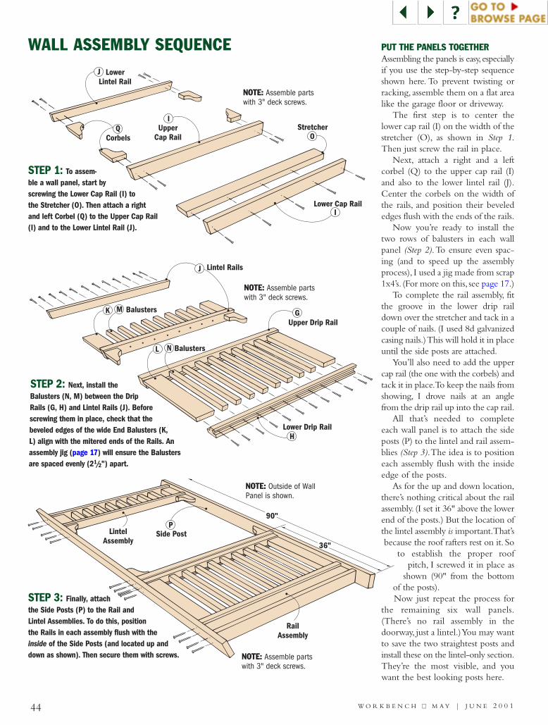
44 W O R K B E N C H ■■ M A Y | J U N E 2 0 0 1
Balusters
Balusters
Lintel Rails
Upper Drip Rail
Lower Drip RailH
K
L
M
N
G
J
Lower Cap Rail
Stretcher
LowerLintel Rail
UpperCap RailCorbels O
QI
I
J
WALL ASSEMBLY SEQUENCE
STEP 1: To assem-ble a wall panel, start byscrewing the Lower Cap Rail (I) tothe Stretcher (O). Then attach a rightand left Corbel (Q) to the Upper Cap Rail(I) and to the Lower Lintel Rail (J).
STEP 3: Finally, attachthe Side Posts (P) to the Rail andLintel Assemblies. To do this, positionthe Rails in each assembly flush with theinside of the Side Posts (and located up anddown as shown). Then secure them with screws.
STEP 2: Next, install theBalusters (N, M) between the DripRails (G, H) and Lintel Rails (J). Beforescrewing them in place, check that thebeveled edges of the wide End Balusters (K,L) align with the mitered ends of the Rails. Anassembly jig (page 17) will ensure the Balustersare spaced evenly (21/2") apart.
PUT THE PANELS TOGETHERAssembling the panels is easy,especiallyif you use the step-by-step sequenceshown here. To prevent twisting orracking, assemble them on a flat arealike the garage floor or driveway.
The first step is to center thelower cap rail (I) on the width of thestretcher (O), as shown in Step 1.Then just screw the rail in place.
Next, attach a right and a leftcorbel (Q) to the upper cap rail (I)and also to the lower lintel rail (J).Center the corbels on the width ofthe rails, and position their bevelededges flush with the ends of the rails.
Now you’re ready to install thetwo rows of balusters in each wallpanel (Step 2).To ensure even spac-ing (and to speed up the assemblyprocess), I used a jig made from scrap1x4’s. (For more on this, see page 17.)
To complete the rail assembly, fitthe groove in the lower drip raildown over the stretcher and tack in acouple of nails. (I used 8d galvanizedcasing nails.) This will hold it in placeuntil the side posts are attached.
You’ll also need to add the uppercap rail (the one with the corbels) andtack it in place.To keep the nails fromshowing, I drove nails at an anglefrom the drip rail up into the cap rail.
All that’s needed to completeeach wall panel is to attach the sideposts (P) to the lintel and rail assem-blies (Step 3).The idea is to positioneach assembly flush with the insideedge of the posts.
As for the up and down location,there’s nothing critical about the railassembly. (I set it 36" above the lowerend of the posts.) But the location ofthe lintel assembly is important.That’sbecause the roof rafters rest on it. So
to establish the proper roofpitch, I screwed it in place as
shown (90" from the bottomof the posts).Now just repeat the process for
the remaining six wall panels.(There’s no rail assembly in thedoorway, just a lintel.) You may wantto save the two straightest posts andinstall these on the lintel-only section.They’re the most visible, and youwant the best looking posts here.
NOTE: Assemble partswith 3" deck screws.
NOTE: Assemble partswith 3" deck screws.
NOTE: Assemble partswith 3" deck screws.
NOTE: Outside of WallPanel is shown.

Side Post
LongSpacerBlock
P
STEP 2:Toenail Spacer
to adjacentpanel with
3"-longdeckingscrews.
STEP 1:Mount
Spacer Blocks(R, S) to left side
of Post.
S
R
3 "!/2
ShortSpacer Block
Tie-down Strap
STEP 3:Secure walls
to tie-down straps.
45W O R K B E N C H ■■ M A Y | J U N E 2 0 0 1
CORNER CONNECTIONMAKING THE CONNECTIONWith most projects, you reach apoint where it really starts to takeshape. For this gazebo, that time isnow — when you begin to connectthe wall panels to each other.
To create the appearance of a thickpost at each corner, the wall panelsare connected by two 2x spacer blocksripped 3" wide (Corner Connection). Ashort (R) and a long spacer block(S) are sandwiched between the sideposts of two adjacent wall panels.
Notice that there’s a 31/2"-tallopening between the two blocks.This opening creates a “pocket” thatwill eventually hold a bench support.
One more thing to be aware of isthat the long spacer block acts as asupport for the hip rafters on the roof.So to ensure proper roof pitch, it’simportant that the upper end of thisblock is even with the top of the lintel.
After cutting the spacer blocks tolength, you can attach them to theside posts.To avoid having two sets ofspacer blocks come together, I madeit a point to screw them to the leftside post of each wall panel (asviewed from the front). Shop Tip:Insert a scrap 2x4 between the blocksto produce the proper size pocket.
UP WITH THE WALLSBefore installing the wall panels, I’dsuggest rounding up a friend to pro-vide a helping hand.The large panelscan be heavy and awkward to handle.
To erect the walls, start to the leftside of where the doorway for the
To fasten two wall panels together, “toe-nail” screws at an angle through thespacer blocks and into the post.
With the wall panels in their final posi-tion, screw the tie-down straps to thespacer blocks (R) at all eight corners.
With the eight wall panels fastened in place, the gazeboreally begins to take shape. At this point, you’re ready tobegin building the roof.
3"
Slot!/8"
R SSidePost Side PostSpacer
BlocksP
P
Tie-down Strap
POST DETAIL
gazebo will be located.Then lift thefirst wall panel and set it on the deck.While your helper holds it upright,slide a second wall panel against itand clamp them together at the cor-ner.The panels are fastened togetherby “toenailing” screws through thespacer blocks and into the side postof the adjacent wall. (See Figure 19and Post Detail below.) Continue likethis, working your way around thegazebo, installing one wall at a time.
The next step is to “anchor” thewalls to the deck by fastening them tothe metal tie-down straps.To do this,tap the walls into place so the shortspacer block (R) is centered on thestrap.Then drive screws through thestrap into the spacer block (Fig. 20).
With the walls in place, stand backand take a minute to admire the gazebobefore starting on the roof (Fig. 21).
19 20 21
NOTE: Locatethe Long SpacerBlock (S) even
with top of LintelAssembly.
NOTE: Turn to page 54for materials and dimensions.
NOTE:Set Spacer Blocks 1/8" back fromoutside of wall to create a recess forthe tie-down strap.

36!/2"
King Post
#8 x 3"Deck Screws
22!/2°
SidePost
76"T
U
VSide Post
NOTE:All Rafters
and Headersare made from
2x lumber.Stub
Rafter
Header
Hip Rafter
King Post
46 W O R K B E N C H ■■ M A Y | J U N E 2 0 0 1
RAFTER ASSEMBLY
45°
KING POST DETAIL
RULES FOR RAFTERSWith the walls complete, it’s time toadd the roof rafters. There are eightlong hip rafters that fit into saddlesformed by the side posts of the walls(Rafter Assembly). These hip raftersconnect to a large, eight-sided blockcalled a king post.There are also eightshort stub rafters that “tie” into head-ers, which span across the hip rafters.
FIT FOR A KING POSTI began by making the thick, eight-sided king post (T) that forms thehub of the rafter system (King PostDetail). It is made up of four 2x8cedar blocks ripped to a width of61/4" and glued together. (I used
polyurethane glue for a waterproofbond.) Once the glue dries, joint allfour sides to make a 6"-square block.
The next step is to lay out theeight sides of the king post.The goalis to end up with eight sides that areequal in size.To do this, locate thecenterpoint of the post by drawingdiagonal lines from corner to corner(Drawing ‘a’). Then set the tip of acompass at the centerpoint and drawa circle that just touches all four sides.
The intersecting points (wherethe compass arc crosses the diagonals)are used to lay out the angled cornersof the block. Set the 45° side of acombination square against the block.Then align the blade with each point
and draw a line across the corner.Tobevel the corners of the post, tilt theblade on your table saw to 45°(Drawing ‘b’).Then set the rip fenceso the blade aligns with the layoutline and bevel the first corner. Nowtrim the remaining corners, rotatingthe post 90° between each pass.
Finally, since the king post will beexposed inside the gazebo, I routed adecorative 1/2" roundover around thebottom edge (Drawing ‘c’).
READY FOR THE RAFTERSWith the king post completed, it’stime to add the roof rafters. Note: Iused 2x6’s (cedar) for all the raftersand headers.
Tilt the blade to 45° and adjustthe fence to line up the cut. Aftereach cut, rotate the block 90°.
Rout a 1/2" roundover around thebottom of the king post to givethe exposed part a finished look.
To lay out the king post’s angledsides, mark across the corners(where arc crosses diagonals).
V
U
U20Bevel
!/2°
W
19"
17 "!/4
HEADER DETAIL
HIP RAFTERSTUB RAFTER
a. b. c.
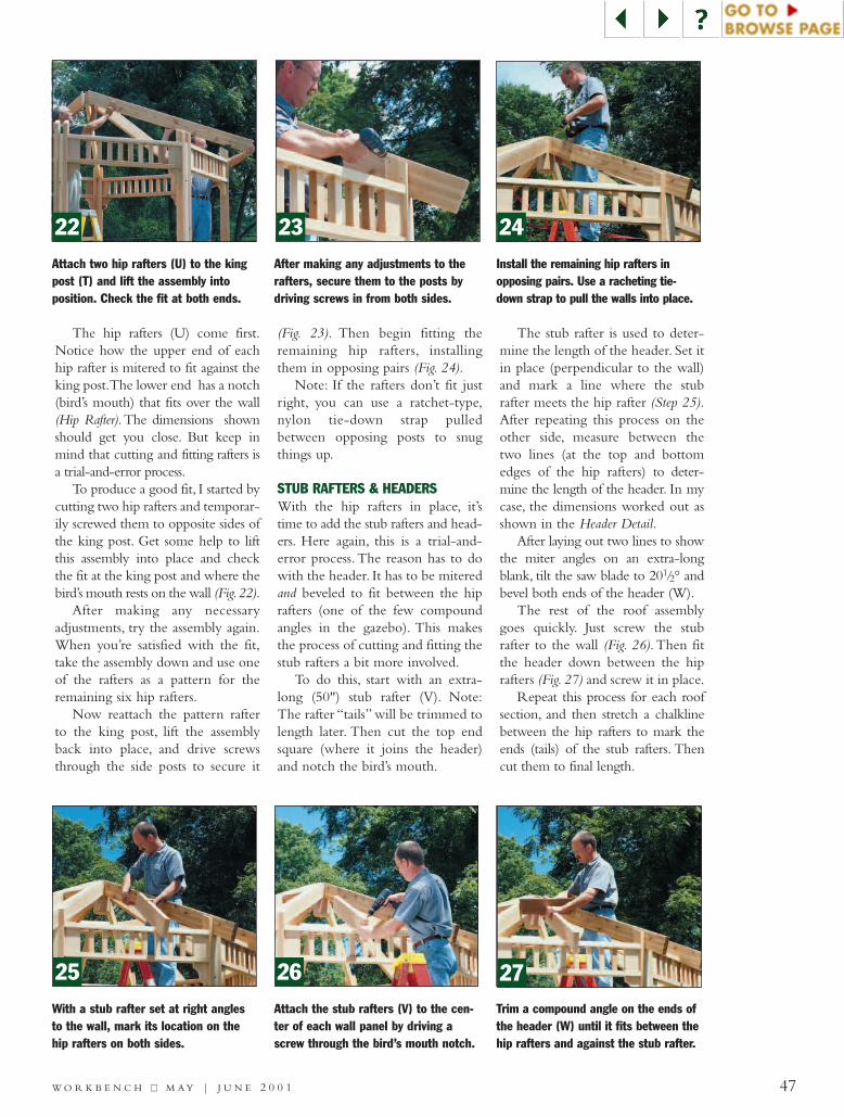
47W O R K B E N C H ■■ M A Y | J U N E 2 0 0 1
The hip rafters (U) come first.Notice how the upper end of eachhip rafter is mitered to fit against theking post.The lower end has a notch(bird’s mouth) that fits over the wall(Hip Rafter). The dimensions shownshould get you close. But keep inmind that cutting and fitting rafters isa trial-and-error process.
To produce a good fit, I started bycutting two hip rafters and temporar-ily screwed them to opposite sides ofthe king post. Get some help to liftthis assembly into place and checkthe fit at the king post and where thebird’s mouth rests on the wall (Fig.22).
After making any necessaryadjustments, try the assembly again.When you’re satisfied with the fit,take the assembly down and use oneof the rafters as a pattern for theremaining six hip rafters.
Now reattach the pattern rafterto the king post, lift the assemblyback into place, and drive screwsthrough the side posts to secure it
(Fig. 23). Then begin fitting theremaining hip rafters, installingthem in opposing pairs (Fig. 24).
Note: If the rafters don’t fit justright, you can use a ratchet-type,nylon tie-down strap pulledbetween opposing posts to snugthings up.
STUB RAFTERS & HEADERSWith the hip rafters in place, it’stime to add the stub rafters and head-ers. Here again, this is a trial-and-error process. The reason has to dowith the header. It has to be miteredand beveled to fit between the hiprafters (one of the few compoundangles in the gazebo). This makesthe process of cutting and fitting thestub rafters a bit more involved.
To do this, start with an extra-long (50") stub rafter (V). Note:The rafter “tails” will be trimmed tolength later. Then cut the top endsquare (where it joins the header)and notch the bird’s mouth.
The stub rafter is used to deter-mine the length of the header. Set itin place (perpendicular to the wall)and mark a line where the stubrafter meets the hip rafter (Step 25).After repeating this process on theother side, measure between thetwo lines (at the top and bottomedges of the hip rafters) to deter-mine the length of the header. In mycase, the dimensions worked out asshown in the Header Detail.
After laying out two lines to showthe miter angles on an extra-longblank, tilt the saw blade to 201/2° andbevel both ends of the header (W).
The rest of the roof assemblygoes quickly. Just screw the stubrafter to the wall (Fig. 26). Then fitthe header down between the hiprafters (Fig. 27) and screw it in place.
Repeat this process for each roofsection, and then stretch a chalklinebetween the hip rafters to mark theends (tails) of the stub rafters. Thencut them to final length.
Attach two hip rafters (U) to the kingpost (T) and lift the assembly intoposition. Check the fit at both ends.
After making any adjustments to therafters, secure them to the posts bydriving screws in from both sides.
Install the remaining hip rafters inopposing pairs. Use a racheting tie-down strap to pull the walls into place.
Attach the stub rafters (V) to the cen-ter of each wall panel by driving ascrew through the bird’s mouth notch.
With a stub rafter set at right anglesto the wall, mark its location on thehip rafters on both sides.
Trim a compound angle on the ends ofthe header (W) until it fits between thehip rafters and against the stub rafter.
22 23 24
25 26 27

Trim Strip(1x2 cedar)Fascia Board
(1x8 cedar)Edge Slat(1x6 pine)
Roof Slat (1x4 pine)Cedar
Shingles
Position this edge about5 " from the King Post.!/2
AA
X
Y
Z
Y
Y
Y
48 W O R K B E N C H ■■ M A Y | J U N E 2 0 0 1
SHEATHING & SHINGLES
SSKKIILLLL BBUUIILLDDEERR
5"
MetalDrip Edge
U
1 "!/2
Y
P UZ
AA
X
SHEATHING DETAIL
SHINGLE DETAIL
1!/2"
Spacer
5d Galv.Box Nails
Tack a 1x6 edge slat (X) to the rafters, aligning it flushwith the ends of the rafter tails.
Tack 1x4 roof slats (Y) in place, leaving them extra longon each end. Use a chalkline to mark them to length.
Hold a 1x8 fascia (Z) against the rafters and mark the com-pound angle needed. Fit each board to the previous one.
SHEATH THE ROOFThe roof of the gazebo is coveredwith cedar shingles that are nailedto evenly-spaced wood slats. Thespace between the slats allows air tocirculate so the shingles can dry outbetween rains.
To provide ample nailing surfacefor the starter course of shingles, Iused a 1x6 for the edge slat (X), asshown in Figure 28. With the edgeslat in place, tack on 1x4 roof slats(Y), letting the ends run past the hipline (Fig. 29 and box below). Note: Inailed the slats at the hip and stubrafters with 5d galvanized box nails.
The last roof slat (the one near-est the peak) should stop about51/2" from the edge of the kingpost.This will leave space for air tocirculate up into the cupola. Withthe slats in place, snap a chalklinedown the center of each hip and
then trim the slats to length. Youcan measure the slats on the firstroof section to cut identical slats forthe seven remaining sections.
CUSTOM FIT THE FASCIAThe edge of the roof is wrappedwith 1x8 cedar fascia boards (Z) anda 1x2 trim strip (AA) as shown inthe Sheathing Detail. The fasciaattaches to the ends of the rafters,while the trim strip keeps the dripedge away from the fascia board.
Because the ends of the rafterstip inward, the ends of the fascia aremitered and beveled — the secondcompound angle in the gazebo.Here’s an easy way to determinethis angle. Hold an extra-long fasciaboard against the rafters (Fig. 30),and mark the rafter centerline at thetop and bottom of the fascia board.Take the board down and draw a
While installing the sheathing, Iused a spacer like the one shownhere to ensure proper spacingbetween the slats. It’s made of twopieces of 11/2"-wide stock that are screwedtogether to form an “X”.The shape keepsthe spacer from “falling through the cracks.”
28
29
30

49W O R K B E N C H ■■ M A Y | J U N E 2 0 0 1
GET GOOD GRADES WITH CEDAR SHINGLESThe lumberyard where I boughtthe cedar shingles for the gazebosold two grades: #1 (Blue Label)and #2 (Red Label).
Shingles that are #1 gradehave straight, parallel grain with-out any knots, cracks, holes orother defects. As a result, theyresist cupping and twisting.
The shingles graded #2 areanother good option. But theyhave flat grain on the face of theshingle (the U-shaped pattern of
the grain) as well as wide colorvariations and a few defectsabove the exposed face. Becauseof the defects, nailing into themwill sometimes cause splitting oreven loosen knots.
In the end, I chose #1 gradeshingles for the gazebo. Withproper care and maintenance,they’ll last many years.
Expect to pay more for the #1cedar shingles. (In my area theycost nearly $50 a bundle, while
#2 came in closer to $40.) But Ithought the extra cost wasworth it for theirappearance anddurability.
Tack the drip edge in place and sightalong the ridge line to mark it tolength. Nail it to the sheathing.
Let a shingle overlap the ridge line,then use a straight edge to mark theangle. The shingles overhang 1".
With a double starter course installed,measure and mark a 5" reveal to posi-tion each subsequent course.
Alternate wide and narrow shinglesand overlap the joints in the coursebelow. Drive one nail near each edge.
Fit beveled cap shingles along theridge line. Roofing felt goes undereach course to help prevent leaks.
31 32 33
34 35
line between the two marks toestablish the miter angle. Thenadjust the saw for a 221/2° bevel andcut along the layout line.
After nailing the first fascia boardin place, cut the same compoundangle on one end of the secondboard. Then fit that end against thefirst board, mark the opposite end asbefore, and trim the second piece tolength. Continue this process as youwork your way around the gazebo.
Finally, use the same process toinstall the cedar trim strips (AA)and the metal drip edge (Fig. 31).
BRING ON THE SHINGLESThe starter course of shingles is twolayers thick and extends 1" beyondthe drip edge. At each end of thecourse, cut the shingles at an angle tomatch the angle of the hip rafters(Fig. 32).
With the starter course complete,measure up 5" for each subsequentcourse (Fig. 33). Be sure to mix up
the shingle widths randomly andoverlap the joint between shingles onthe previous course. Keep in mindthat cedar shingles need to “breathe,”so don’t overdo the nails. Two nailsper shingle near the edges is all that’sneeded (Fig. 34).
One thing to mention here is Iplanned to install a working cupolafor ventilation.To provide air circu-lation, I didn’t shingle completely tothe top. Instead, the shingles stop flushwith the top edge of the last slat.
Note: If you plan to build thecupola, it needs to be installed now— before attaching the cap shinglesthat go on next. (For instructions onbuilding the cupola, see page 50.)
CAP THE HIPSTo complete the shingling,you’ll needto “cap” the seams along the hips (Fig.35).To do this, rip 3"-wide shinglesand bevel their mating edges at 15°.For extra protection, I placed roofingfelt under the cap shingles.
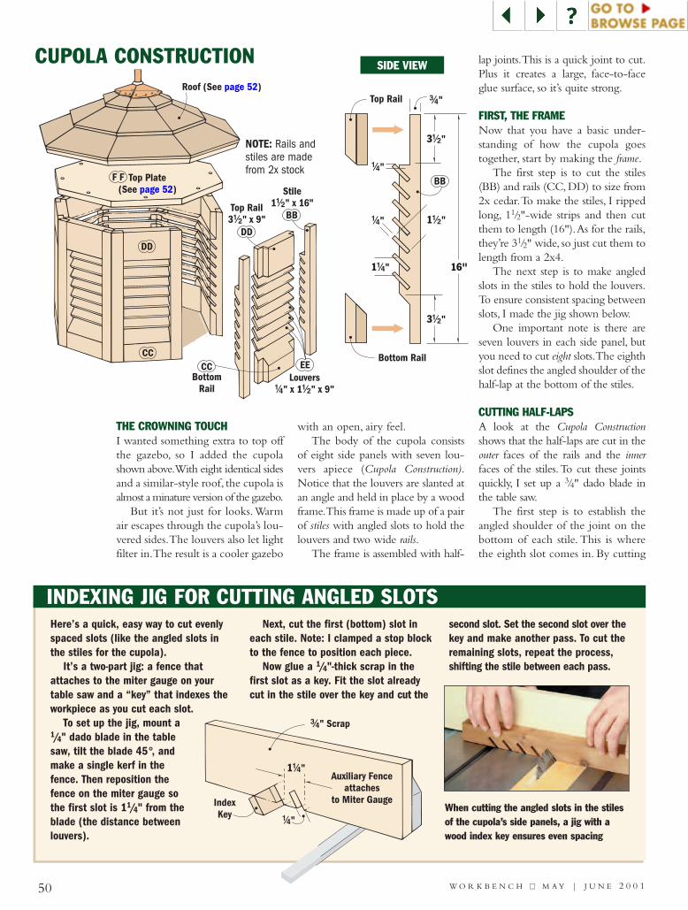
BB
1!/2"
3!/2"
#/4"
Bottom Rail
16"1!/4"
!/4"
3!/2"
!/4"
Top Rail
Stile1 " x 16"!/2Top Rail
3 " x 9"!/2
Roof (See page 52)
Top Plate(See page 52)
Louvers" x 1 " x 9"!/4 !/2
BB
CC
BottomRail
CC
DDDD
F F
EE
50 W O R K B E N C H ■■ M A Y | J U N E 2 0 0 1
CUPOLA CONSTRUCTION
INDEXING JIG FOR CUTTING ANGLED SLOTS
SIDE VIEW
When cutting the angled slots in the stilesof the cupola’s side panels, a jig with awood index key ensures even spacing
#/4" Scrap
1!/4"
!/4"
Auxiliary Fenceattaches
to Miter GaugeIndexKey
THE CROWNING TOUCHI wanted something extra to top offthe gazebo, so I added the cupolashown above.With eight identical sidesand a similar-style roof, the cupola isalmost a minature version of the gazebo.
But it’s not just for looks.Warmair escapes through the cupola’s lou-vered sides.The louvers also let lightfilter in.The result is a cooler gazebo
with an open, airy feel.The body of the cupola consists
of eight side panels with seven lou-vers apiece (Cupola Construction).Notice that the louvers are slanted atan angle and held in place by a woodframe.This frame is made up of a pairof stiles with angled slots to hold thelouvers and two wide rails.
The frame is assembled with half-
lap joints.This is a quick joint to cut.Plus it creates a large, face-to-faceglue surface, so it’s quite strong.
FIRST, THE FRAMENow that you have a basic under-standing of how the cupola goestogether, start by making the frame.
The first step is to cut the stiles(BB) and rails (CC, DD) to size from2x cedar.To make the stiles, I rippedlong, 11/2"-wide strips and then cutthem to length (16").As for the rails,they’re 31/2" wide, so just cut them tolength from a 2x4.
The next step is to make angledslots in the stiles to hold the louvers.To ensure consistent spacing betweenslots, I made the jig shown below.
One important note is there areseven louvers in each side panel, butyou need to cut eight slots.The eighthslot defines the angled shoulder of thehalf-lap at the bottom of the stiles.
CUTTING HALF-LAPSA look at the Cupola Constructionshows that the half-laps are cut in theouter faces of the rails and the innerfaces of the stiles.To cut these jointsquickly, I set up a 3/4" dado blade inthe table saw.
The first step is to establish theangled shoulder of the joint on thebottom of each stile. This is wherethe eighth slot comes in. By cutting
Here’s a quick, easy way to cut evenlyspaced slots (like the angled slots inthe stiles for the cupola).
It’s a two-part jig: a fence thatattaches to the miter gauge on yourtable saw and a “key” that indexes theworkpiece as you cut each slot.
To set up the jig, mount a1/4" dado blade in the tablesaw, tilt the blade 45°, andmake a single kerf in thefence. Then reposition thefence on the miter gauge sothe first slot is 11/4" from theblade (the distance betweenlouvers).
Next, cut the first (bottom) slot ineach stile. Note: I clamped a stop blockto the fence to position each piece.
Now glue a 1/4"-thick scrap in thefirst slot as a key. Fit the slot alreadycut in the stile over the key and cut the
second slot. Set the second slot over thekey and make another pass. To cut theremaining slots, repeat the process,shifting the stile between each pass.
NOTE: Rails andstiles are madefrom 2x stock

51W O R K B E N C H ■■ M A Y | J U N E 2 0 0 1
#/4"1 "!/2
#/4"
Wedge
#/4"#/4"
DD
22 °!/2
The blade must be close enough to thelast slot to remove the small wedge ofwaste under the slot.
To rip the top rail, tilt the saw blade to45°. Then adjust the rip fence to cut a3/4" bevel as shown in the detail.
Without changing the dado bladesetup, cut a half-lap joint in each endof the top and bottom rails.
up close to this slot, a small wedgeof waste material will fall away toform the angled shoulder (Fig. 36).
Once that first cut is made, slidethe stile over on the miter gauge andplough out the remaining waste.
The next step is to cut the half-lapat the top of the stile.To establish theshoulder of this half-lap, I used myrip fence to position the stiles on themiter gauge.To do this, butt the endof the workpiece against the fenceand then use the miter gauge to pushthe stile through the saw blade.
After wasting out the remainingstock, you can cut the half-laps in therails. Here again, use the rip fence toposition each rail as you cut theshoulder of the joint.Then shift therail to the side to remove the rest ofthe waste (Fig. 37).
All that’s left to complete the railsis to cut a bevel in each piece (CupolaConstruction, Side View). To provideclearance for the louvers, cut a nar-row bevel on the lower, inside edgeof the top rail (Fig. 38).Also, cuttinga wide bevel on the bottom railforms a water-shedding surface thatmatches the angle of the louvers.
At this point it’s time to makethe louvers.Altogether, there are 56louvers, and I wanted each one tobe the exact same thickness to fit inthe angled slots. So I made a jig forthe table saw that provides a quick,easy way to cut the louvers (EE) touniform thickness. (For a look atthis jig, turn to page 17.)
Now it’s just a matter of gluingup the side panels. Start by gluing
the louvers into the slots (Fig.39) withwater-resistant, yellow woodworker’sglue. (I used Titebond II.) Then glueand clamp the frames together.
There’s just one thing left tocomplete the side panels.To get theeight sides to fit together, you’llneed to rip a bevel on each of thelong edges, as shown in Figure 40.
ADD THE TOP PLATEBefore gluing the side panelstogether, it’s best to make the topplate (Cupola Construction). It addsrigidity when gluing up the cupola.
The top plate (FF) is a piece of3/4" plywood that’s cut to the shapeof an octagon. Here again, the goal isto end up with eight sides of equallength. So I used the same procedureas with the king post to lay out thesides. Only this time, I started with a213/4"-square blank (the distance acrosstwo opposing sides of the cupola).
After cutting the top to shape, it’stime to glue up the eight side panels.This isn’t as difficult as it might seem,especially if you have a couple ofband clamps on hand.
Start by applying water-resistantglue to the beveled edges of the pan-els.Then stand the panels on end andfit them together. Now slip on theband clamps and slowly draw themsnug (not tight) against the side panels.
All thats left is to set the top platein place and tap the side pan-els flush (if necessary). Finally,screw the top plate in placeand tighten the clamps.
Glue the louvers into the slots cut in the stiles. The slatends should be flush with the outer edge of the stiles.
With the side panel face down on the table saw, bevel thetwo long edges of each side panel at a 221/2° angle.
36 37 38
39
40
First Cut

GG
HH
HH
Trim Strip" x 1 "#/4 !/2
CedarShingles
RoofFelt
RoofPiece
6d GalvanizedFinish Nail
3"
52 W O R K B E N C H ■■ M A Y | J U N E 2 0 0 1
#8 x 3"Fh Woodscrew
RoofSlat
CUPOLA ROOF ASSEMBLY
CUPOLA MOUNTING DETAIL
CAPPING THE CUPOLAOverall, the cupola roof is a minordetail, but building it is one of themost interesting parts of this project.
The challenge is to cut eight iden-tical triangles to form the roof. Assimple as that sounds, consider thatthe long edges of each triangle arebeveled at 10° — that’s 16 compoundcuts that need to be precisely the same.
Before you decide you don’t wanta cupola after all, take a look at thefollowing steps. They’ll simplify theprocess considerably. To get started,you’ll need a piece of 3/4"-thick ply-
wood large enough to cut all eighttriangles (141/4" wide × 48" long).Now set your table saw up to cut thetriangles. First, mount an auxiliaryfence to your miter gauge and tiltthe gauge 201/2° degrees. Finally, tiltthe blade to 10°.
With your table saw set up thisway, cut a kerf in the auxiliary fence.This kerf will be used as a referencethat will be used to position the ply-wood when cutting each triangle.
To make the first cut, place theplywood against the auxiliary fenceand position the corner of the ply-wood against the reference kerf (Fig.41).Now make the first cut to removea wedge-shaped, waste piece.
It’s the second cut that will makethe first roof piece (GG).To do this,flip the plywood edge-for-edge, andalign the new corner with the kerf(Fig. 42).Then make the cut, flip theplywood, align the corner, and makeanother cut. Continue this way untilyou’ve cut all eight roof pieces.
Tilt the blade to 10° and the mitergauge to 201/2°. Trim one end of theplywood blank.
Flip the plywood over, align the tip ofthe triangle to the outside of the kerfin the fence and cut the second side.
Tape the triangles edge-to-edge with thethe bevels down. (That extra space willclose up when you “raise” the roof.)
Carefully turn the roof over and brush agenerous amount of glue in each jointand on one of the two exposed edges.
Turn the roof back over and pull thelast joint together. Then tape it closedand let the glue dry overnight.
41 42 43
44 45
Measure and mark 12" down from thecenter of the king post along each hip.Use these marks to center the cupola.
46
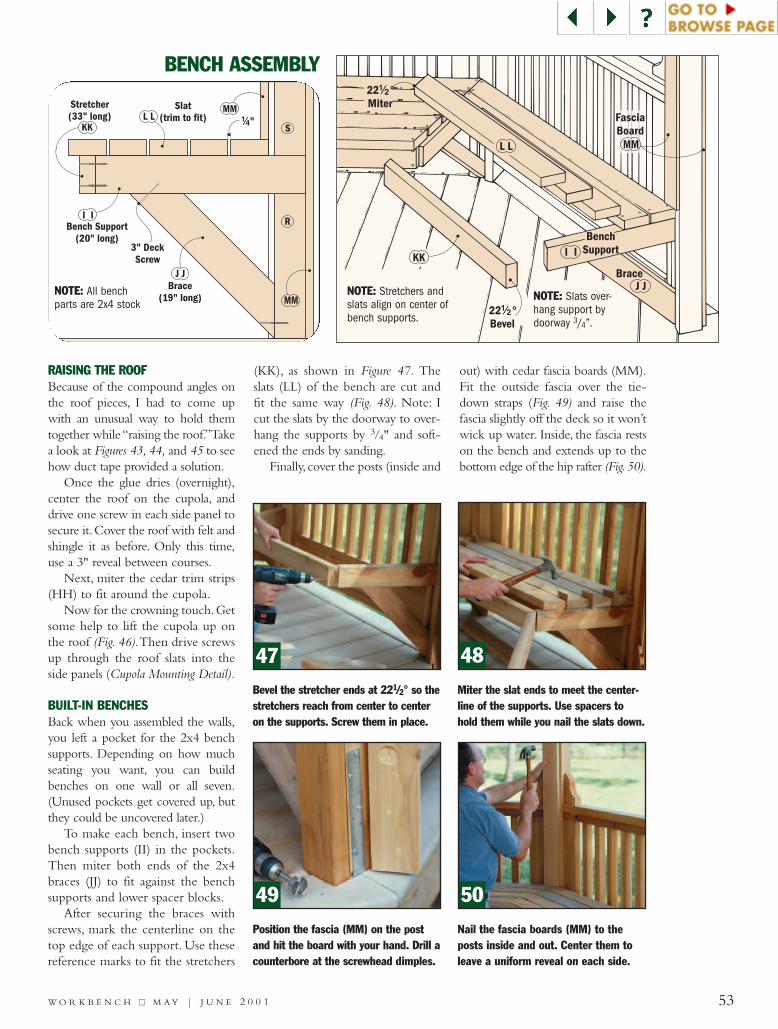
NOTE: Slats over-hang support bydoorway 3/4”.
NOTE: Stretchers andslats align on center ofbench supports.
Brace(19" long)
3" DeckScrew
Bench Support(20" long)
Slat(trim to fit) !/4"
Stretcher(33" long)
J J
KKL L
I I
S
R
MM
MM
53W O R K B E N C H ■■ M A Y | J U N E 2 0 0 1
BENCH ASSEMBLY
RAISING THE ROOFBecause of the compound angles onthe roof pieces, I had to come upwith an unusual way to hold themtogether while “raising the roof.”Takea look at Figures 43, 44, and 45 to seehow duct tape provided a solution.
Once the glue dries (overnight),center the roof on the cupola, anddrive one screw in each side panel tosecure it.Cover the roof with felt andshingle it as before. Only this time,use a 3" reveal between courses.
Next, miter the cedar trim strips(HH) to fit around the cupola.
Now for the crowning touch.Getsome help to lift the cupola up onthe roof (Fig. 46).Then drive screwsup through the roof slats into theside panels (Cupola Mounting Detail).
BUILT-IN BENCHESBack when you assembled the walls,you left a pocket for the 2x4 benchsupports. Depending on how muchseating you want, you can buildbenches on one wall or all seven.(Unused pockets get covered up, butthey could be uncovered later.)
To make each bench, insert twobench supports (II) in the pockets.Then miter both ends of the 2x4braces (JJ) to fit against the benchsupports and lower spacer blocks.
After securing the braces withscrews, mark the centerline on thetop edge of each support. Use thesereference marks to fit the stretchers
(KK), as shown in Figure 47. Theslats (LL) of the bench are cut andfit the same way (Fig. 48). Note: Icut the slats by the doorway to over-hang the supports by 3/4" and soft-ened the ends by sanding.
Finally, cover the posts (inside and
out) with cedar fascia boards (MM).Fit the outside fascia over the tie-down straps (Fig. 49) and raise thefascia slightly off the deck so it won’twick up water. Inside, the fascia restson the bench and extends up to thebottom edge of the hip rafter (Fig.50).
Bevel the stretcher ends at 221/2° so thestretchers reach from center to centeron the supports. Screw them in place.
Miter the slat ends to meet the center-line of the supports. Use spacers tohold them while you nail the slats down.
Position the fascia (MM) on the postand hit the board with your hand. Drill acounterbore at the screwhead dimples.
Nail the fascia boards (MM) to theposts inside and out. Center them toleave a uniform reveal on each side.
47 48
49 50
NOTE: All benchparts are 2x4 stock
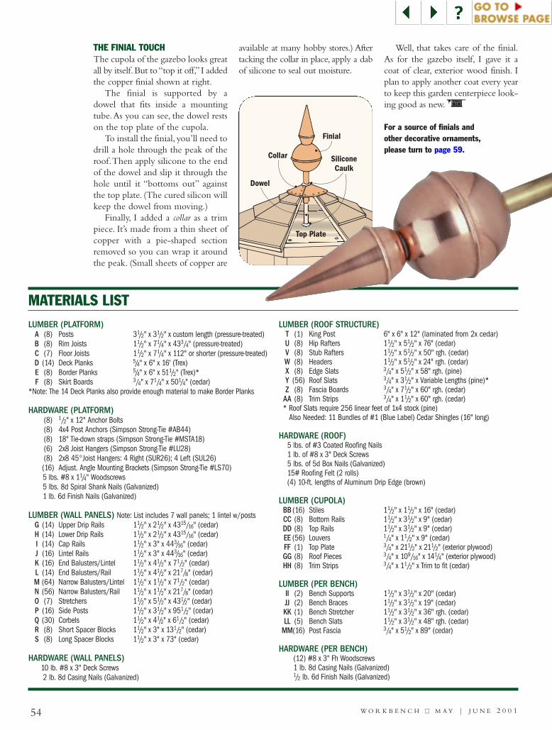
54 W O R K B E N C H ■■ M A Y | J U N E 2 0 0 1
LUMBER (PLATFORM)A (8) Posts 31/2" x 31/2" x custom length (pressure-treated)B (8) Rim Joists 11/2" x 71/4" x 433/4" (pressure-treated)C (7) Floor Joists 11/2" x 71/4" x 112" or shorter (pressure-treated)D (14) Deck Planks 5/4" x 6" x 16' (Trex)E (8) Border Planks 5/4" x 6" x 511/2" (Trex)*F (8) Skirt Boards 3/4" x 71/4" x 501/4" (cedar)
*Note: The 14 Deck Planks also provide enough material to make Border Planks
HARDWARE (PLATFORM)(8) 1/2" x 12" Anchor Bolts(8) 4x4 Post Anchors (Simpson Strong-Tie #AB44)(8) 18" Tie-down straps (Simpson Strong-Tie #MSTA18)(6) 2x8 Joist Hangers (Simpson Strong-Tie #LU28)(8) 2x8 45°Joist Hangers: 4 Right (SUR26); 4 Left (SUL26)(16) Adjust. Angle Mounting Brackets (Simpson Strong-Tie #LS70)5 lbs. #8 x 11/4" Woodscrews5 lbs. 8d Spiral Shank Nails (Galvanized)1 lb. 6d Finish Nails (Galvanized)
LUMBER (WALL PANELS) Note: List includes 7 wall panels; 1 lintel w/postsG (14) Upper Drip Rails 11/2" x 21/2" x 4315/16" (cedar)H (14) Lower Drip Rails 11/2" x 21/2" x 4315/16" (cedar)I (14) Cap Rails 11/2" x 3" x 443/16" (cedar)J (16) Lintel Rails 11/2" x 3" x 443/16" (cedar)K (16) End Balusters/Lintel 11/2" x 41/2" x 71/2" (cedar)L (14) End Balusters/Rail 11/2" x 41/2" x 217/8" (cedar)M (64) Narrow Balusters/Lintel 11/2" x 11/2" x 71/2" (cedar)N (56) Narrow Balusters/Rail 11/2" x 11/2" x 217/8" (cedar)O (7) Stretchers 11/2" x 51/2" x 431/2" (cedar)P (16) Side Posts 11/2" x 31/2" x 951/2" (cedar)Q (30) Corbels 11/2" x 41/2" x 61/2" (cedar)R (8) Short Spacer Blocks 11/2" x 3" x 131/2" (cedar)S (8) Long Spacer Blocks 11/2" x 3" x 73" (cedar)
HARDWARE (WALL PANELS)10 lb. #8 x 3" Deck Screws2 lb. 8d Casing Nails (Galvanized)
LUMBER (ROOF STRUCTURE) T (1) King Post 6" x 6" x 12" (laminated from 2x cedar)U (8) Hip Rafters 11/2" x 51/2" x 76" (cedar)V (8) Stub Rafters 11/2" x 51/2" x 50" rgh. (cedar)W (8) Headers 11/2" x 51/2" x 24" rgh. (cedar)X (8) Edge Slats 3/4" x 51/2" x 58" rgh. (pine)Y (56) Roof Slats 3/4" x 31/2" x Variable Lengths (pine)*Z (8) Fascia Boards 3/4" x 71/2" x 60" rgh. (cedar)
AA (8) Trim Strips 3/4" x 11/2" x 60" rgh. (cedar)* Roof Slats require 256 linear feet of 1x4 stock (pine)
Also Needed: 11 Bundles of #1 (Blue Label) Cedar Shingles (16" long)
HARDWARE (ROOF)5 lbs. of #3 Coated Roofing Nails1 lb. of #8 x 3" Deck Screws5 lbs. of 5d Box Nails (Galvanized)15# Roofing Felt (2 rolls)(4) 10-ft. lengths of Aluminum Drip Edge (brown)
LUMBER (CUPOLA)BB (16) Stiles 11/2" x 11/2" x 16" (cedar)CC (8) Bottom Rails 11/2" x 31/2" x 9" (cedar)DD (8) Top Rails 11/2" x 31/2" x 9" (cedar)EE (56) Louvers 1/4" x 11/2" x 9" (cedar)FF (1) Top Plate 3/4" x 211/2" x 211/2" (exterior plywood)GG (8) Roof Pieces 3/4" x 109/16" x 141/4" (exterior plywood)HH (8) Trim Strips 3/4" x 11/2" x Trim to fit (cedar)
LUMBER (PER BENCH)II (2) Bench Supports 11/2" x 31/2" x 20" (cedar)JJ (2) Bench Braces 11/2" x 31/2" x 19" (cedar)KK (1) Bench Stretcher 11/2" x 31/2" x 36" rgh. (cedar)LL (5) Bench Slats 11/2" x 31/2" x 48" rgh. (cedar)
MM(16) Post Fascia 3/4" x 51/2" x 89" (cedar)
HARDWARE (PER BENCH)(12) #8 x 3" Fh Woodscrews1 lb. 8d Casing Nails (Galvanized)1/2 lb. 6d Finish Nails (Galvanized)
MATERIALS LIST
SiliconeCaulk
Collar
Top Plate
Finial
Dowel
THE FINIAL TOUCHThe cupola of the gazebo looks greatall by itself.But to “top it off,” I addedthe copper finial shown at right.
The finial is supported by adowel that fits inside a mountingtube.As you can see, the dowel restson the top plate of the cupola.
To install the finial, you’ll need todrill a hole through the peak of theroof.Then apply silicone to the endof the dowel and slip it through thehole until it “bottoms out” againstthe top plate. (The cured silicon willkeep the dowel from moving.)
Finally, I added a collar as a trimpiece. It’s made from a thin sheet ofcopper with a pie-shaped sectionremoved so you can wrap it aroundthe peak. (Small sheets of copper are
available at many hobby stores.) Aftertacking the collar in place, apply a dabof silicone to seal out moisture.
Well, that takes care of the finial.As for the gazebo itself, I gave it acoat of clear, exterior wood finish. Iplan to apply another coat every yearto keep this garden centerpiece look-ing good as new.
For a source of finials andother decorative ornaments,please turn to page 59.
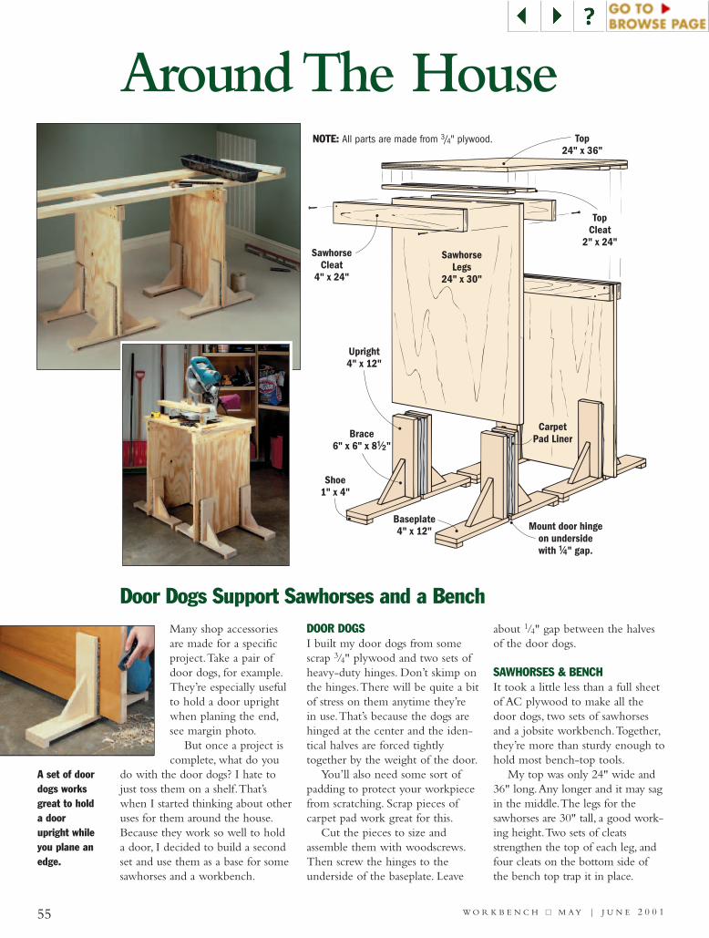
55 W O R K B E N C H ■■ M A Y | J U N E 2 0 0 1
Around The House
Many shop accessoriesare made for a specificproject.Take a pair ofdoor dogs, for example.They’re especially usefulto hold a door uprightwhen planing the end,see margin photo.
But once a project iscomplete, what do you
do with the door dogs? I hate tojust toss them on a shelf.That’swhen I started thinking about otheruses for them around the house.Because they work so well to holda door, I decided to build a secondset and use them as a base for somesawhorses and a workbench.
DOOR DOGSI built my door dogs from somescrap 3/4" plywood and two sets ofheavy-duty hinges. Don’t skimp onthe hinges.There will be quite a bitof stress on them anytime they’rein use.That’s because the dogs arehinged at the center and the iden-tical halves are forced tightlytogether by the weight of the door.
You’ll also need some sort ofpadding to protect your workpiecefrom scratching. Scrap pieces ofcarpet pad work great for this.
Cut the pieces to size andassemble them with woodscrews.Then screw the hinges to theunderside of the baseplate. Leave
about 1/4" gap between the halvesof the door dogs.
SAWHORSES & BENCHIt took a little less than a full sheetof AC plywood to make all thedoor dogs, two sets of sawhorsesand a jobsite workbench.Together,they’re more than sturdy enough tohold most bench-top tools.
My top was only 24" wide and36" long.Any longer and it may sagin the middle.The legs for thesawhorses are 30" tall, a good work-ing height.Two sets of cleatsstrengthen the top of each leg, andfour cleats on the bottom side ofthe bench top trap it in place.
Door Dogs Support Sawhorses and a Bench
Baseplate4" x 12" Mount door hinge
on undersidewith " gap.!/4
Shoe1" x 4"
Brace6" x 6" x 8 "!/2
Upright4" x 12"
SawhorseLegs
24" x 30"
TopCleat
2" x 24"Sawhorse
Cleat4" x 24"
Top24" x 36"
CarpetPad Liner
NOTE: All parts are made from 3/4" plywood.
A set of doordogs worksgreat to holda doorupright whileyou plane anedge.

56W O R K B E N C H ■■ M A Y | J U N E 2 0 0 1
A dimmer switch is one of those lit-tle conveniences that, once installed,you’ll wonder how you ever livedwithout it.The good thing is thatany standard, single-pole wall switchis a great candidate for replacementwith a dimmer switch.There are justa couple of requirements: ampleroom in the switch’s electrical box,and the light source must be incan-descent (uses regular bulbs).
Replacing a single-pole switchwith a dimmer is easy. Note: Alwaysstart by flipping the breaker off at theservice panel and then testing to seethat power isn’t reaching the switch.
After the power is off, removethe old switch from the electricalbox as shown in Figure 1 and dis-connect the wires.Then connectthe circuit wires to the dimmer’stwo lead wires and secure withwire nuts (Fig. 2). If your dimmer
switch has a ground (green) wire(not all do), attach it to the circuit’sgrounding wire or directly to agrounded metal electrical box.
Then it’s just a matter of pushingeverything back into the box, turn-ing on the power, and testing thenew dimmer switch.
I like to use plain wood knobs onmy garage or basement cabinets.But it’s frustrating when the knobsspin when I pull the drawers open.The wood knobs that I use — thekind with a single screw — oftentwist loose from use.To keep thisfrom happening, drill a small pilothole in the back of the knob.Theninsert a brad in the knob and clipoff the head, leaving about an 1/8"showing.Tightening the screwdraws the nail into the drawer frontso the knob won’t spin.
Drywall anchors work great tohang items where there isn’t a studto nail or screw into.That’s becausethey have metal “fingers” thatmushroom inside the wall once amachine screw is threaded in.Afterthe fingers grip the drywall, theanchor is locked in place.
There’s one problem, though —it’s permanent.What if you everwant to remove the anchor? It’snearly impossible to get the anchorout without leaving a large hole inthe wall that has to be patched.
But you don’t have to remove theanchors to get rid of them.An easysolution to this problem is to dim-ple the head of the anchor with ahammer and nailset (Fig. 1).To endup with a dimple deep enough topatch effectively, give the head acouple of firm whacks. Just becareful not to overdo it.Then allyou need is a small amount ofpatching compound to create asmooth surface that’s easy to paintover later (Fig. 2).
Adding a New Dimmer Switch is a Simple Task
Stop Knobs fromTwisting Loose
Covering Unsightly Drywall Anchors
Brad
ScrewWoodKnob
DrawerFront
Nailset
DrywallAnchor
PuttyKnife
Anchor
Patch dimplewith joint
compound.
Circuit Wires
Terminal Screw
Ground Wire
Box
Single-PoleSwitch
CircuitWires
LeadWires
GroundWires
DimmerSwitch
Box
1211
NOTE: Dimmerswitches come in a
variety of styles.Check the installa-tion instructionsthat accompany
your switch.
1
2
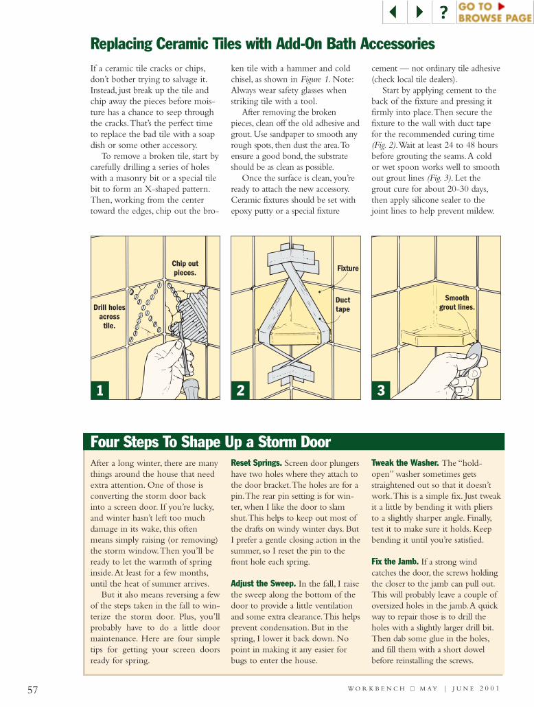
57 W O R K B E N C H ■■ M A Y | J U N E 2 0 0 1
If a ceramic tile cracks or chips,don’t bother trying to salvage it.Instead, just break up the tile andchip away the pieces before mois-ture has a chance to seep throughthe cracks.That’s the perfect timeto replace the bad tile with a soapdish or some other accessory.
To remove a broken tile, start bycarefully drilling a series of holeswith a masonry bit or a special tilebit to form an X-shaped pattern.Then, working from the centertoward the edges, chip out the bro-
ken tile with a hammer and coldchisel, as shown in Figure 1. Note:Always wear safety glasses whenstriking tile with a tool.
After removing the brokenpieces, clean off the old adhesive andgrout. Use sandpaper to smooth anyrough spots, then dust the area.Toensure a good bond, the substrateshould be as clean as possible.
Once the surface is clean, you’reready to attach the new accessory.Ceramic fixtures should be set withepoxy putty or a special fixture
cement — not ordinary tile adhesive(check local tile dealers).
Start by applying cement to theback of the fixture and pressing itfirmly into place.Then secure thefixture to the wall with duct tapefor the recommended curing time(Fig. 2).Wait at least 24 to 48 hoursbefore grouting the seams.A coldor wet spoon works well to smoothout grout lines (Fig. 3). Let thegrout cure for about 20-30 days,then apply silicone sealer to thejoint lines to help prevent mildew.
After a long winter, there are manythings around the house that needextra attention. One of those isconverting the storm door backinto a screen door. If you’re lucky,and winter hasn’t left too muchdamage in its wake, this oftenmeans simply raising (or removing)the storm window.Then you’ll beready to let the warmth of springinside.At least for a few months,until the heat of summer arrives.
But it also means reversing a fewof the steps taken in the fall to win-terize the storm door. Plus, you’llprobably have to do a little doormaintenance. Here are four simpletips for getting your screen doorsready for spring.
Reset Springs. Screen door plungershave two holes where they attach tothe door bracket.The holes are for apin.The rear pin setting is for win-ter, when I like the door to slamshut.This helps to keep out most ofthe drafts on windy winter days. ButI prefer a gentle closing action in thesummer, so I reset the pin to thefront hole each spring.
Adjust the Sweep. In the fall, I raisethe sweep along the bottom of thedoor to provide a little ventilationand some extra clearance.This helpsprevent condensation. But in thespring, I lower it back down. Nopoint in making it any easier forbugs to enter the house.
Tweak the Washer. The “hold-open” washer sometimes getsstraightened out so that it doesn’twork.This is a simple fix. Just tweakit a little by bending it with pliersto a slightly sharper angle. Finally,test it to make sure it holds. Keepbending it until you’re satisfied.
Fix the Jamb. If a strong windcatches the door, the screws holdingthe closer to the jamb can pull out.This will probably leave a couple ofoversized holes in the jamb.A quickway to repair those is to drill theholes with a slightly larger drill bit.Then dab some glue in the holes,and fill them with a short dowelbefore reinstalling the screws.
Replacing Ceramic Tiles with Add-On Bath Accessories
Four Steps To Shape Up a Storm Door
Chip outpieces.
Drill holesacross
tile.
Ducttape
Fixture
Smoothgrout lines.
321

58 W O R K B E N C H ■■ M A Y | J U N E 2 0 0 1
Quick Stucco Repair: Rebuild It in Three CoatsCracks and holes are an inevitablepart of stucco exteriors.To preventfurther damage, remove any loosestucco right away (Fig. 1). It soundscrazy, but you’ll actually want toincrease the size of the damagedarea.After blowing out the dust, sta-ple new wire mesh in place.
To rebuild the stucco, you’ll needto mist the area with water andapply three coats. Spread on a basecoat to within 1/4" of the surface(Fig. 2).When firm, score the surfaceand allow it to cure for two days.Again, mist with water and apply thesecond coat to within 1/8" of the
surface.The finish coat is appliedflush with the existing surface.
While it’s wet, texture to match.In Figure 3, you’ll see a thrown-onspatter (stipple) texture.To finishup, smooth any high spots, andcover the repair with plastic forfour days while the stucco cures.
Loose Stucco
WireMesh
Applybase coat
" belowsurface.!/4
ToothedKnife
Applyfinish coatflush withsurface.
Spatter/StippleTexture
2
3
1
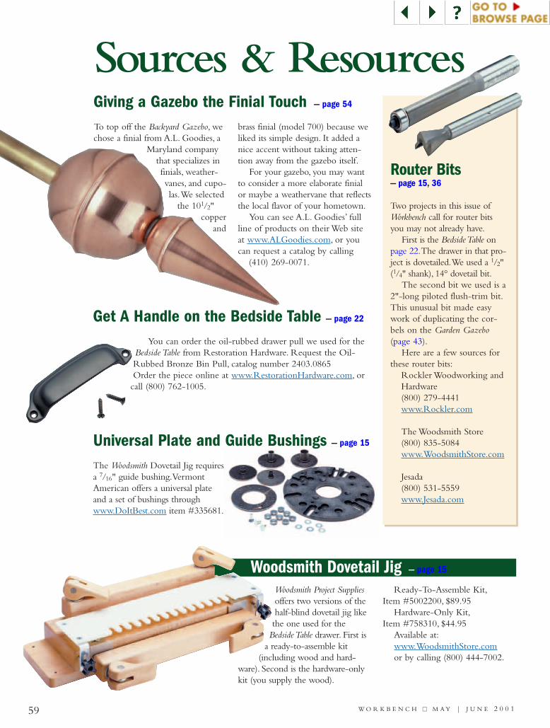
Woodsmith Dovetail Jig — page 15
59 W O R K B E N C H ■■ M A Y | J U N E 2 0 0 1
Giving a Gazebo the Finial Touch — page 54
Get A Handle on the Bedside Table — page 22
Router Bits— page 15, 36
To top off the Backyard Gazebo, wechose a finial from A.L. Goodies, a
Maryland companythat specializes infinials, weather-vanes, and cupo-las.We selected
the 101/2"copper
and
brass finial (model 700) because weliked its simple design. It added anice accent without taking atten-tion away from the gazebo itself.
For your gazebo, you may wantto consider a more elaborate finialor maybe a weathervane that reflectsthe local flavor of your hometown.
You can see A.L. Goodies’ fullline of products on their Web siteat www.ALGoodies.com, or youcan request a catalog by calling
(410) 269-0071.
Two projects in this issue ofWorkbench call for router bitsyou may not already have.
First is the Bedside Table onpage 22.The drawer in that pro-ject is dovetailed.We used a 1/2"(1/4" shank), 14° dovetail bit.
The second bit we used is a2"-long piloted flush-trim bit.This unusual bit made easywork of duplicating the cor-bels on the Garden Gazebo(page 43).
Here are a few sources forthese router bits:
Rockler Woodworking andHardware(800) 279-4441www.Rockler.com
The Woodsmith Store(800) 835-5084www.WoodsmithStore.com
Jesada(800) 531-5559www.Jesada.com
The Woodsmith Dovetail Jig requiresa 7/16" guide bushing.VermontAmerican offers a universal plateand a set of bushings throughwww.DoItBest.com item #335681.
Universal Plate and Guide Bushings — page 15
Sources & Resources
You can order the oil-rubbed drawer pull we used for theBedside Table from Restoration Hardware. Request the Oil-Rubbed Bronze Bin Pull, catalog number 2403.0865Order the piece online at www.RestorationHardware.com, or
call (800) 762-1005.
Woodsmith Project Suppliesoffers two versions of thehalf-blind dovetail jig likethe one used for the
Bedside Table drawer. First isa ready-to-assemble kit
(including wood and hard-ware). Second is the hardware-onlykit (you supply the wood).
Ready-To-Assemble Kit,Item #5002200, $89.95
Hardware-Only Kit,Item #758310, $44.95
Available at:www.WoodsmithStore.comor by calling (800) 444-7002.

60 W O R K B E N C H ■■ M A Y | J U N E 2 0 0 1
Yankee Ingenuity!In the 1940s, manufacturers
were busy making guns, ammocasings, and other ordnance forthe Allies. As a result, manyitems were rationed — clothes,shoes, meat, gasoline, and evenelectric motors.
Yet Americans still needed tomaintain their homes. So man-ufacturers such as Arco and the
Mall Tool Company respondedwith some clever tools. Oneidea that proved successful wasinterchangeable attachmentsthat turned a power drill into adisc sander, grinder, hack saw,screwdriver, drill press, polisher,planer, even a circular saw.
Suddenly, homeowners couldaccomplish “Most Everything
Around the House or Farm”with a single tool. And at only$8-$10 each, these attachmentswere much less expensive thancomparable full-sized tools.
This accounts for theirpopularity throughout the ’40sand ’50s — proof that with alittle Yankee ingenuity, you canfind a way to get the job done.
C R A F T S M A N S H I P