work zone safety - virginia
TRANSCRIPT

Work Zone Safety
Revised September 2019
Guidelines forTemporary
Traffic Control
1
Table of ContentsIntroduction 3Traffic Control Devices 4 Signs 4 Channelizing Devices 7 Lighting Devices 11 Portable Temporary Rumble Strips 13Shadow Vehicles 15Truck Mounted Attenuators 15Component Parts of a Temporary Traffic Control Zone 16Taper Length Criteria for Work Zones 18Work Zone Application in Curves and Hills 20Installing/Removing Lane Closures 21 Installing Lane Closures 22 Removing Lane Closures 23 Definitions 24Typical Application Diagrams 26 Work Outside the Shoulder 27 Permitted Temporary Entrance 29 Shoulder Work –
Mobile or Short Duration Operation 31 Shoulder Work – Stationary Operation 33 Shoulder Work with Minor Encroachment – Stationary Operation 35 Four-lane Road – Mobile Operation 37 Four-lane Non Limited Access –
Short Duration Operation 39 Four-lane – Stationary Right Lane Closure 41
Four-lane Road – Stationary Left Lane Closure 43 Center Turn Lane Closure on a Three-lane, Two-way Road 45
2
Table of Contents Lane Shift on a Three-lane,Two-way Road 47 Two-lane Road – Mobile Operation 49 Two-lane Road – Mowing With Encroachment 51 Two-lane Road – Stationary Closure 53 Automatic Flagger Assistance Device - Stop/Slow 55 Red/Yellow Lens 57 Two-Lane Roadway – Temporary Disruption 59 Multi-Lane Roadway – Temporary Disruption 61 Turn Lane Stationary Closure 63 Lane Closure in Advance of Intersection 65
Closure in Center of Intersection 67 Partial Ramp Closure Operation 69 Surveying Operations 71 Flagging Procedures 73 Liability 76 Daily Checklist for Temporary Traffic Control 77 Intersection Sight Distance 78
3
IntroductionThe purpose of this handbook is to present basic guidelines for work zone traffic control and to supplement the 2011 Virginia Work Area Protection Manual with Revision 1. This handbook presents the requirements of Part VI of the Manual on Uniform Traffic Control Devices (MUTCD) with particular emphasis on short term work sites on roads and streets in rural and urban areas. These requirements apply to temporary traffic control zones, as found in construction, maintenance, and utility work areas. This handbook presents information and gives examples of typical traffic control applications for two-lane and multilane work zones. This information is intended to illustrate the principles of proper work zone traffic control, but is not a standard. The Virginia Work Area Protection Manual contains the standards for temporary traffic control zones for roadways in Virginia and can be accessed at VirginiaDOT.org, Business Center.
4
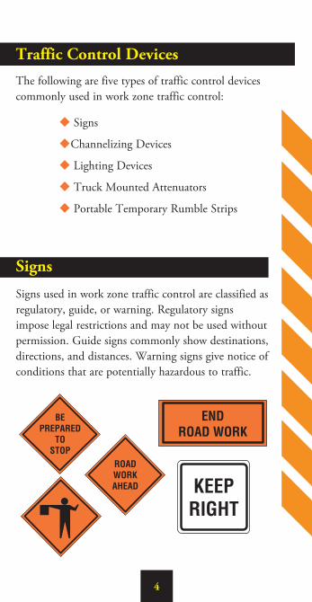
Traffic Control Devices The following are five types of traffic control devices commonly used in work zone traffic control:
u Signs
uChannelizing Devices
u Lighting Devices
u Truck Mounted Attenuators
u Portable Temporary Rumble Strips
Signs
Signs used in work zone traffic control are classified as regulatory, guide, or warning. Regulatory signs impose legal restrictions and may not be used without permission. Guide signs commonly show destinations, directions, and distances. Warning signs give notice of conditions that are potentially hazardous to traffic.

5
Warning SignsConstruction and maintenance warning signs are used extensively in street and highway work zones. These signs are normally diamond shaped, having a black symbol or message on an orange background. As a general rule, these signs are located on the right-hand side of the street or highway. On divided roadways with a median of 8' or greater, both left and right sides shall be signed. Smaller sign sizes may be used in the median when the median width is between 6.5 feet and 8 feet to provide left sign assemblies on a multilane roadway. SizeThe standard size for advance warning signs in work zones is generally 48" by 48". Where Right of Way or geometric conditions preclude use of 48" by 48" signs, 36" by 36" signs may be used.
MountingStandards for height and lateral clearance of post mounted roadside signs are included in the Virginia Work Area Protection Manual. Signs mounted on temporary supports may be at lower heights but the bottom of the sign shall not be less than one foot above the pavement elevation.
6
Warning Signs
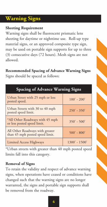
Sheeting RequirementWarning signs shall be fluorescent prismatic lens sheeting for daytime or nighttime use. Roll-up type material signs, or an approved composite type sign, may be used on portable sign supports for up to three (3) consecutive days (72 hours). Mesh signs are not allowed.
Recommended Spacing of Advance Warning SignsSigns should be spaced as follows:
Spacing of Advance Warning Signs
Urban Street with 25 mph or less posted speed. 100' - 200'
Urban Streets with 30 to 40 mph posted speed limit. 250' - 350'
*All Other Roadways with 45 mph or less posted speed limit. 350' - 500'
All Other Roadways with greater than 45 mph posted speed limit. 500' - 800'
Limited Access Highways 1300' - 1500'
*Urban streets with greater than 40 mph posted speed limits fall into this category.
Removal of SignsTo retain the validity and respect of advance warning signs, when operations have ceased or conditions have changed such that the warning signs are no longer warranted, the signs and portable sign supports shall be removed from the roadway.
7
Channelizing Devices
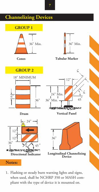
Cones
36" Min.
18" MINIMUM
Drum
36"6"
36" Min.
Tubular Marker
GROUP 1
Notes:
1. Flashing or steady burn warning lights and signs, when used, shall be NCHRP 350 or MASH com-pliant with the type of device it is mounted on.
12"
45o
4"
4"24" Min.
36" Min.
Vertical Panel
12" Min.
GROUP 2
24"
36"36"
12"
12"
4" 45 o
Directional Indicator Longitudinal ChannelizingDevice
8
Channelizing Devices
Notes:
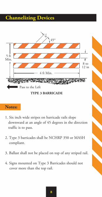
1. Six inch wide stripes on barricade rails slope downward at an angle of 45 degrees in the direction traffic is to pass.
2. Type 3 barricades shall be NCHRP 350 or MASH compliant.
3. Ballast shall not be placed on top of any striped rail.
4. Signs mounted on Type 3 Barricades should not cover more than the top rail.
8 to 12 in
45o
5 ft Min.
4 ft Min.
TYPE 3 BARRICADE
Pass to the Left
6"
9
Channelizing Devices (continued)
Channelizing devices are used to warn and alert drivers of hazards in work zones, to protect workers, and safely guide and direct drivers past the hazards. Channelizing devices include cones, tubular markers, drums, vertical panels, temporary raised islands, directional indicators, and longitudinal channelizing devices. The most common channelizing device used in short term work sites is the traffic cone.
Traffic ConesTraffic cones shall be orange in color and a minimum of 36 inches in height. Cones used at night shall be retroreflectorized by a 6 inch band and a 4 inch band space 2 inches a part. Cones greater than 36" in height shall have four alternating orange and white retroreflective stripes respectively 4" to 6" wide.
Vertical PanelsVertical panels shall be 12 inches in width and at least 24 inches in height. They shall have 6 inch orange and white diagonal stripes and shall be retroreflectorized. Vertical panels shall be mounted with the top a minimum of 36 inches above the roadway.
Directional Indicators and Longitudinal Channelizing DevicesDirectional indicators and longitudinal channelizing devices shall comply with the descriptions on Page 7. Directional indicators shall only be used in tapers. Longitudinal channelizing devices shall interlock and may be used in place of cones or drums.

10
Channelizing Devices
SpacingChannelizing devices should be spaced so that they make it apparent that the roadway or work area is closed to traffic. To accomplish this, the devices should be spaced based on the posted speed and by the following guidelines:
Spacing of Channelizing Devices
Work Zone Location Posted Speed Limit Spacing
In Tapers and Curves 35 mph or less 20'
Parallel to the Travelway 35 mph or less 40'
Spot Construction Access* 35 mph or less 80'
In Tapers and Curves Greater than 35 mph 40'
Parallel to the Travelway Greater than 35 mph 80'
Spot Construction Access* Greater than 35 mph 120'
* For easier access by construction vehicles into the work area, spacings may be increased to this distance, but shall not exceed one access per quarter mile.
DrumsPlastic drums must be a minimum of 36 inches in height and at least 18 inches in diameter with alternating orange and white retroreflective stripes 6 inches wide. Each drum shall have a minimum of two orange and white stripes, and the top stripe shall be orange. Spacing of drums shall be the same as for cones. To ensure that the work zone is properly protected, drums shall be used to delineate unmanned work areas.
11
Lighting Devices
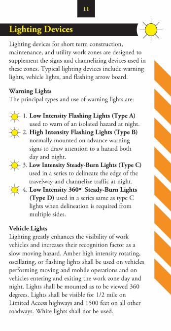
Lighting devices for short term construction, maintenance, and utility work zones are designed to supplement the signs and channelizing devices used in these zones. Typical lighting devices include warning lights, vehicle lights, and flashing arrow board.
Warning LightsThe principal types and use of warning lights are:
1. Low Intensity Flashing Lights (Type A) used to warn of an isolated hazard at night.
2. High Intensity Flashing Lights (Type B)normally mounted on advance warning signs to draw attention to a hazard both day and night.
3. Low Intensity Steady-Burn Lights (Type C)used in a series to delineate the edge of the travelway and channelize traffic at night.
4. Low Intensity 360º Steady-Burn Lights (Type D) used in a series same as type C lights when delineation is required from multiple sides.
Vehicle LightsLighting greatly enhances the visibility of work vehicles and increases their recognition factor as a slow moving hazard. Amber high intensity rotating, oscillating, or flashing lights shall be used on vehicles performing moving and mobile operations and on vehicles entering and exiting the work zone day and night. Lights shall be mounted as to be viewed 360 degrees. Lights shall be visible for 1/2 mile on Limited Access highways and 1500 feet on all other roadways. White lights shall not be used.
12
Lighting Devices
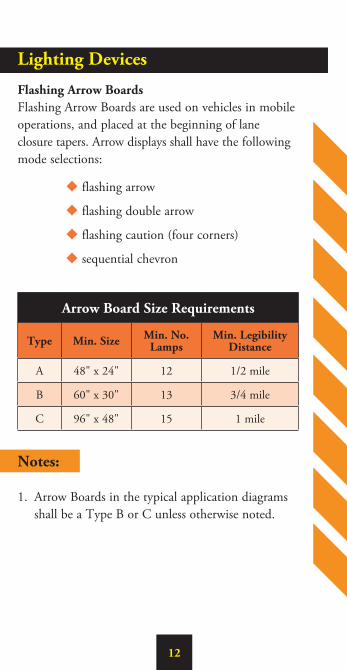
Flashing Arrow BoardsFlashing Arrow Boards are used on vehicles in mobile operations, and placed at the beginning of lane closure tapers. Arrow displays shall have the following mode selections:
u flashing arrow
u flashing double arrow
u flashing caution (four corners)
u sequential chevron
Arrow Board Size Requirements
Type Min. Size Min. No. Lamps
Min. Legibility Distance
A 48" x 24" 12 1/2 mile
B 60" x 30" 13 3/4 mile
C 96" x 48" 15 1 mile
Notes:
1. Arrow Boards in the typical application diagrams shall be a Type B or C unless otherwise noted.
13
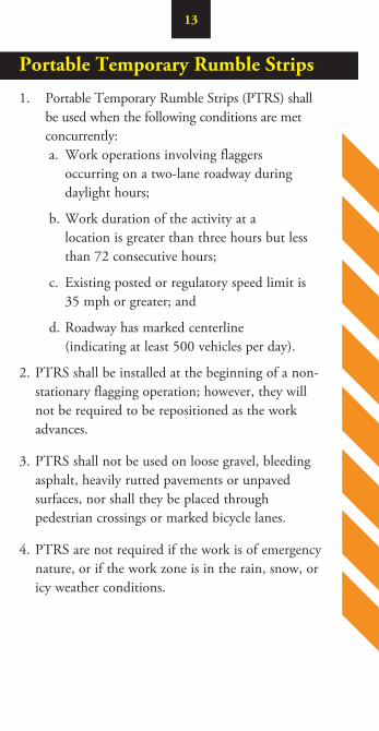
Portable Temporary Rumble Strips
1. Portable Temporary Rumble Strips (PTRS) shall be used when the following conditions are met concurrently:a. Work operations involving flaggers
occurring on a two-lane roadway during daylight hours;
b. Work duration of the activity at a location is greater than three hours but less than 72 consecutive hours;
c. Existing posted or regulatory speed limit is 35 mph or greater; and
d. Roadway has marked centerline (indicating at least 500 vehicles per day).
2. PTRS shall be installed at the beginning of a non-stationary flagging operation; however, they will not be required to be repositioned as the work advances.
3. PTRS shall not be used on loose gravel, bleeding asphalt, heavily rutted pavements or unpaved surfaces, nor shall they be placed through pedestrian crossings or marked bicycle lanes.
4. PTRS are not required if the work is of emergency nature, or if the work zone is in the rain, snow, or icy weather conditions.
14
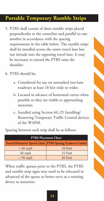
5. PTRS shall consist of three rumble strips placed perpendicular to the centerline and parallel to one another in accordance with the spacing requirements in the table below. The rumble strips shall be installed across the entire travel lane but not intrude into the opposing travel lane. It may be necessary to extend the PTRS onto the shoulder.
6. PTRS should be:
a. Considered for use on unmarked two-lane roadways at least 18 feet wide or wider.
b. Located in advance of horizontal curves when possible so they are visible to approaching motorists.
c. Installed using Section 6G.25 Installing/Removing Temporary Traffic Control devices of the WAPM.
Spacing between each strip shall be as follows:
When traffic queues prior to the PTRS, the PTRS and rumble strip signs may need to be relocated in advanced of the queue to better serve as a warning device to motorists.
Portable Temporary Rumble Strips
PTRS Placement Chart
Posted/Statutory Speed Limit PTRS Spacing (Center to Center)
< 40 mph 10 Feet40 mph 15 Feet
> 50 mph 20 Feet
15
Shadow Vehicles
A shadow vehicle (see Truck Mounted Attenuators) shall be placed 80’ to120’ in advance of the first work crew encountered by traveling motorists. A shadow vehicle should be used when installing and removing TTC devices and be placed 80’ to 120’ in advance of the each work crew. Each shadow vehicle shall have at least one amber high intensity rotating, oscillating, or flashing light functioning while in operation. A work vehicle shall be used to store, install and remove TTC devices.
Truck Mounted AttenuatorsA shadow vehicle requires a truck or trailer mounted attenuator (TMA) in all lane and/or partial ramp closures on four or more lane roadways when the posted speed limit is 45 mph or greater, and for mobile operations which fully or partially block a lane on roadways posted 45 mph or greater. All TMA units shall conform to the requirements of NCHRP 350 - Test Level 3 or MASH regardless of where the unit will be used.
Placement of shadow vehicle with the TMA shall be 80' to 120' in front of the first work crew, equipment, or hazard encountered by traveling motorists. A shadow vehicle should be placed 80’ to 120’ in advance of the each work crew. Each TMA vehicle shall have at least one amber high intensity rotating, oscillating, or flashing light functioning while in operation.
16
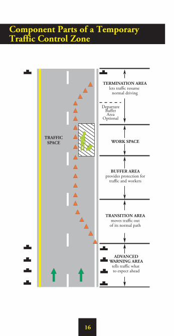
WORK SPACETRAFFIC
SPACE
BUFFER AREAprovides protection for
traffic and workers
TRANSITION AREAmoves traffic outof its normal path
ADVANCEDWARNING AREA
tells traffic what to expect ahead
Departure Buffer Area
Optional
TERMINATION AREAlets traffic resume
normal driving
Component Parts of a Temporary Traffic Control Zone
17
Five Parts of a Temporary Traffic Control Zone
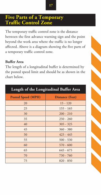
The temporary traffic control zone is the distance between the first advance warning sign and the point beyond the work area where the traffic is no longer affected. Above is a diagram showing the five parts of a temporary traffic control zone.
Buffer AreaThe length of a longitudinal buffer is determined by the posted speed limit and should be as shown in the chart below.
Length of the Longitudinal Buffer Area
Posted Speed (MPH) Distance (Feet)
20 15 - 12025 155 - 16530 200 - 21035 250 - 26040 305 - 32545 360 - 38050 425 - 44555 500 - 53060 570 - 60065 645 - 67570 730 - 76075 820 - 850

18
Taper Length Criteria for Work Zones
There are five types of tapers used in work zone traffic control. The length of each type of taper is based on the speed of traffic and the width of the offset (or lane width). The following are the five types of tapers and their lengths.
Type of Taper Taper LengthMerging L MinimumShifting See Table BelowShoulder 1/3 L MinimumTwo-way 50 to 100 Ft.
Downstream 50 Ft. Min. to 100 Ft. Max.
Taper Length (L)
Speed (S) in MPH
Width of Offset (W) in Ft.Remarks
9 10 11 12
25 or below 95 105 115 125 L=S2W/60
30 135 150 165 180 "35 185 205 225 245 "
40 240 270 295 320 "45 405 450 495 540 L=SW
50 450 500 550 600 "55 495 550 605 660 "
60 540 600 660 720 "65 585 650 715 780 "
70 630 700 770 840 “
Limited Access Highways shall use a 1000’ merging taper regardless of the speed limit.
Shifting Tapers—full lane width shifts on Limited Access Highways shall use a 750’ shifting taper for posted speeds
less than 65 mph and a 1000’ shifting taper for posted speeds equal to or greater than 65 mph. For all other
roadways, 3/4 L should be used.

19
Types of Tapers and Buffer Spaces
Merging Taper
LongitudinalBuffer Space
Shifting Taper
3/4 L
Lateral BufferSpace
(optional)
Lateral BufferSpace
(optional)
L
Shifting Taper3/4 L 3/4 LShifting
Taper
1/3 L
Shoulder Taper
LongitudinalBuffer Space
Four AdditionalChannelizing Devices
Four AdditionalChannelizing Devices
Downstream Taper
LongitudinalBuffer Space
WorkSpace
20
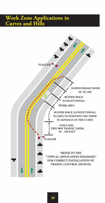
BUFFER SPACE (LONGITUDINAL)IS USED TO POSITION THE TAPER
IN ADVANCE OF THE CURVE
WORK AREA
FLAGGER
FLAGGER
ONE-LANE, TWO-WAY TRAFFIC TAPER
50 – 100 FEET
BUFFER SPACE(LONGITUDINAL)
DOWNSTREAM TAPER50' TO 100'
*REFER TO THE “TYPICAL APPLICATION DIAGRAMS”
FOR CORRECT INSTALLATION OF TRAFFIC CONTROL DEVICES.
Work Zone Applications in Curves and Hills

21
Work Zone Applications in Curves and Hills
When the work activity occurs in a curve or the down side of a hill, consideration should be given to the placement of the advanced warning devices. It’s always best to place the warning signs, arrow board, and taper devices in a tangent section of roadway for maximum visibility. This may involve extending the lane closure and increasing the buffer space to accomplish. If the lane closure cannot be lengthened due to roadway constraints, then the length of the taper should increase to provide additional merge area for vehicles. On hills, the signs, taper, arrow board and flagger stations should be seen prior to reaching the crest of the hill.
Care must be exercised when installing and removing lane closures. All stationary lane closures begin and end as mobile operations. TTC devices shall not be stored, installed or removed from a shadow vehicle. All TTC devices shall be stored, installed or removed from a work operation vehicle. The traffic control needed to perform the operation safely is dictated by the location on the roadway the mobile operation will occur; either on the shoulder or partially or fully in the lane. A shadow vehicle with a TMA shall be used to protect workers and their work vehicle during the installation and removal of TTC devices.
Installing/Removing Lane Closures

22
Installing Lane Closures
Stationary lane closures should be installed with the flow of traffic in the following sequence:
1. Install all advance warning signs.
2. Install shoulder taper if necessary.
3. Place arrow board on the shoulder at the beginning of the merging taper.
4. Install channelizing devices to form a merging taper.
5. Install channelizing devices along the buffer space.
6. Continue placing channelizing devices along the work area at the appropriate spacing.
7. Install channelizing devices for the termination area.
8. Install the “END ROAD WORK” sign approximately 500' beyond the last device in the lane closure.
9. Place a TMA vehicle, if required, 80'-120' from first work crew or hazard approached by motorists.
A “ride through” through the entire lane closure should be performed (with adjustments made to the traffic control devices if needed) to ensure that the lane closure is installed and functioning properly. Major adjustments to the work zone should be documented.

23
Removing Lane Closures
Stationary lane closures should be removed against the flow of traffic in the following sequence:
1. Remove channelizing devices from end of closure back to the widest part of the merging taper.
2. Place removal vehicle on shoulder and remove devices from taper by hand onto the work vehicle.
3. Remove arrow board after ensuring roadway is clear.
4. Moving with the flow of traffic, remove all of the advance warning signs beginning with the “ROAD WORK AHEAD” sign and ending with the “END ROAD WORK” sign.
Use of a TMA vehicle when installing and removing lane closures on multi-lane roadways increases the safety of the operation for both the worker and the traveling public, and shall be used whenever the shoulder width prevents these operations from being performed completely off of the travelway. When A trailer mounted TMA is used on the shadow vehicle, all devices may be removed with the flow of traffic.Workers running across an open travel lanes of traffic to install and remove TTC devices is a dangerous practice and should not be performed unless slow roll temporary traffic control operations are being performed (see Sections 6G.24 and 6G.25, as well as TTC-62 in the Virginia Work Area Protection Manual).
24
Definitions
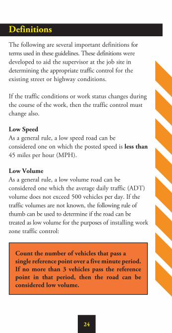
The following are several important definitions for terms used in these guidelines. These definitions were developed to aid the supervisor at the job site in determining the appropriate traffic control for the existing street or highway conditions. If the traffic conditions or work status changes during the course of the work, then the traffic control must change also.
Low SpeedAs a general rule, a low speed road can be considered one on which the posted speed is less than 45 miles per hour (MPH).
Low VolumeAs a general rule, a low volume road can be considered one which the average daily traffic (ADT) volume does not exceed 500 vehicles per day. If the traffic volumes are not known, the following rule of thumb can be used to determine if the road can be treated as low volume for the purposes of installing work zone traffic control:
Count the number of vehicles that pass a single reference point over a five minute period. If no more than 3 vehicles pass the reference point in that period, then the road can be considered low volume.

Definitions (continued)
The following are categories of work duration and their time at a location:
Mobile OperationWork that moves intermittently or continuously (0-15 minutes) and does not occupy the immediate area for more than 15 minutes. The immediate area is typically defined as a 1000 linear foot distance.
Short DurationOccupies a location from 15 minutes to 1 hour.
Short-term Stationary Occupies a location for more than 1 hour but less than 12 hours within a single daylight period.
Intermediate-term stationary Occupies a location more than one daylight period up to 3 days, or nighttime work lasting more than 1 hour.
Long Term Stationary Occupies a location longer than 3 days (72 consecutive hours).
Nighttime ActivitiesTraffic control should be installed for nighttime operations from 30 minutes before sunset to 30 minutes after sunrise.
25
26
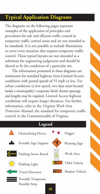
Typical Application Diagrams
The diagrams on the following pages represent examples of the application of principles and procedures for safe and efficient traffic control in temporary traffic control zones and are not intended to be standards. It is not possible to include illustrations to cover every situation that requires temporary traffic control. These typical layouts are not intended as a substitute for engineering judgement and should be altered to fit the conditions of a particular site. The information presented in these diagrams are minimums for standard highway (non-Limited Access) conditions with posted speeds of 55 mph or less. For urban conditions (a low speed, two-lane street located inside a municipality's corporate limit) shorter spacings and lengths may be required. Limited Access highway conditions will require longer distances. For further information, refer to the Virginia Work Area Protection Manual; the standard for temporary traffic control in the Commonwealth of Virginia.
Legend
Channelizing Device
Portable Sign Support
Flashing Arrow Board
Flashing Light
Flagger
Warning Sign
Work Area
TMA Vehicle
Shadow VehicleTravel Direction
Portable Temporary Rumble Strip

DIT
CH
LIN
E
SEE NOTE 3
SEENOTE 1
Work Outside the Shoulder(15' or More From the Edge of Travel Way)
27
28
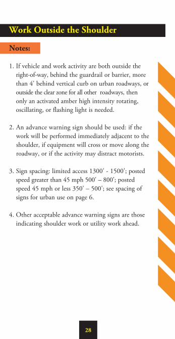
Work Outside the Shoulder
Notes:
1. If vehicle and work activity are both outside the right-of-way, behind the guardrail or barrier, more than 4' behind vertical curb on urban roadways, or outside the clear zone for all other roadways, then only an activated amber high intensity rotating, oscillating, or flashing light is needed.
2. An advance warning sign should be used: if the work will be performed immediately adjacent to the shoulder, if equipment will cross or move along the roadway, or if the activity may distract motorists.
3. Sign spacing: limited access 1300' - 1500'; posted speed greater than 45 mph 500' – 800'; posted speed 45 mph or less 350' – 500'; see spacing of signs for urban use on page 6.
4. Other acceptable advance warning signs are those indicating shoulder work or utility work ahead.
29
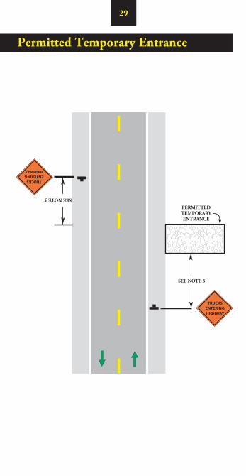
Permitted Temporary Entrance
SEE NOTE 3SEE NOTE 3
PERMITTEDTEMPORARYENTRANCE
TRUCKSENTERINGHIGHWAY
TRUCKSENTERINGHIGHWAY

30
Permitted Temporary Entrance
Notes:
1. Notify the appropriate state or local agencies prior to the installation of the entrance and placement of any traffic control devices.
2. The organization receiving the entrance permit is responsible for removal of all debris (gravel, mud, dust, hauled materials, etc.), obstructions and irregularities caused by the operation. A flagging operation is required for removing debris on a two-lane roadway. A mobile operation is required to remove debris on a multi-lane roadway.
3. Sign spacing: posted speed greater than 45 mph 500' – 800'; posted speed 45 mph or less 350' – 500'; see spacing of signs for urban use on page 6.
31
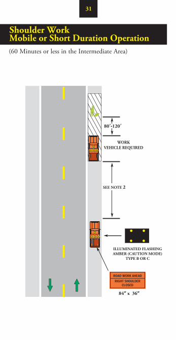
80’-120’
SEE NOTE 2
WORKVEHICLE REQUIRED
ILLUMINATED FLASHINGAMBER (CAUTION MODE)
TYPE B OR C
84” x 36”
Shoulder WorkMobile or Short Duration Operation(60 Minutes or less in the Intermediate Area)

32
Shoulder Work Mobile or Short Duration Operation
Notes:
1. The first shadow vehicle may be replaced with a 48"x 48" “ROAD WORK AHEAD” or “UTILITY WORK AHEAD” sign.
2. The minimum distance between sign and shadow vehicle should be 350'-500' where the posted speed limit is 45 mph or less, and 500'-800' where the posted speed limit is greater than 45 mph. The maximum distance between sign and work vehicle is 2 miles.
3. Each shadow vehicle involved in the operation shall have at least an arrow board operating in the caution mode or at least one amber high intensity rotating, oscillating, or flashing light.
4. When the work operation is off the shoulder with a work duration of 15-60 minutes, vehicle warning lights and a truck mounted sign (W20-V3, W20-V6, W20-V1, etc.) or a sign on a portable sign support shall be placed behind the work operations vehicle.
5. The work area may be delineate by installing channelizing devices.

33
500'
80'-120'
BUFFERSEE NOTE 3
SHADOW VEHICLE REQUIRED
(TMA OPTIONALSEE NOTE 6)
1/3 L TAPER
SEE NOTE 2
SEE NOTE 2
SEE NOTE 2
RIGHTSHOULDER
CLOSED
Shoulder Work - Stationary Operation(Greater Than 60 Minutes in the Immediate Area)
34
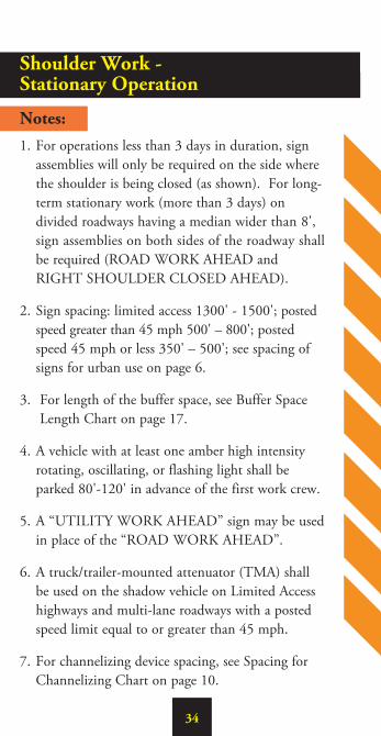
Shoulder Work - Stationary Operation
Notes:1. For operations less than 3 days in duration, sign
assemblies will only be required on the side where the shoulder is being closed (as shown). For long-term stationary work (more than 3 days) on divided roadways having a median wider than 8', sign assemblies on both sides of the roadway shall be required (ROAD WORK AHEAD and RIGHT SHOULDER CLOSED AHEAD).
2. Sign spacing: limited access 1300' - 1500'; posted speed greater than 45 mph 500' – 800'; posted speed 45 mph or less 350' – 500'; see spacing of signs for urban use on page 6.
3. For length of the buffer space, see Buffer Space Length Chart on page 17.
4. A vehicle with at least one amber high intensity rotating, oscillating, or flashing light shall be parked 80'-120' in advance of the first work crew.
5. A “UTILITY WORK AHEAD” sign may be used in place of the “ROAD WORK AHEAD”.
6. A truck/trailer-mounted attenuator (TMA) shall be used on the shadow vehicle on Limited Access highways and multi-lane roadways with a posted speed limit equal to or greater than 45 mph.
7. For channelizing device spacing, see Spacing for Channelizing Chart on page 10.
35
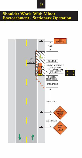
Shoulder Work With Minor Encroachment - Stationary Operation
500'
10'MIN. 80'-120'
BUFFER
SHADOW VEHICLE REQUIRED
(TMA OPTIONALSEE NOTE 7)
1/3 L TAPER
SEE NOTE 2
SEE NOTE 2
SEE NOTE 3
36
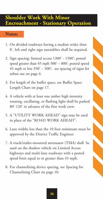
Shoulder Work With Minor Encroachment - Stationary Operation
Notes:
1. On divided roadways having a median wider than 8', left and right sign assemblies shall be required.
2. Sign spacing: limited access 1300' - 1500'; posted speed greater than 45 mph 500' – 800'; posted speed 45 mph or less 350' – 500'; see spacing of signs for urban use on page 6.
3. For length of the buffer space, see Buffer Space Length Chart on page 17.
4. A vehicle with at least one amber high intensity rotating, oscillating, or flashing light shall be parked 80'-120' in advance of the first work crew.
5. A “UTILITY WORK AHEAD” sign may be used in place of the “ROAD WORK AHEAD”.
6. Lane widths less than the 10 foot minimum must be approved by the District Traffic Engineer.
7. A truck/trailer-mounted attenuator (TMA) shall be used on the shadow vehicle on Limited Access highways and multi-lane roadways with a posted speed limit equal to or greater than 45 mph.
8. For channelizing device spacing, see Spacing for Channelizing Chart on page 10.
37
1000'
WORK OPERATIONSVEHICLE
84" x 36"
84" x 36"
SEE NOTE 3
SEE NOTE 2)(
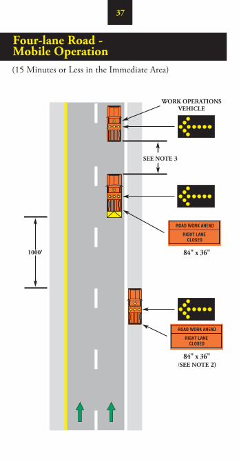
Four-lane Road - Mobile Operation(15 Minutes or Less in the Immediate Area)
38
Four-lane Road - Mobile Operation
Notes:
1. Each vehicle involved in the mobile operation shall be equipped with at least one amber high intensity rotating, oscillating, or flashing light. All vehicles shown shall have an arrow panel operating in the flashing arrow mode.
2. If the shadow vehicle occupies any part of the travel lane, it shall have a TMA.
3. When the work operations vehicle is stationary, the TMA vehicle shall be in a position 80' – 120' in advance of the work operations vehicle. When the work operations vehicle is moving, the TMA vehicle shall follow at a distance of 240'+.
4. The static warning sign and arrow board may be replaced with a vehicle mounted changeable message sign (CMS) with a minimum of 10" height characters.
5. On Limited Access highways an additional TMA vehicle (not shown) is required. Shadow vehicle 1 is on the shoulder, TMA vehicle 2 straddles the edge line and TMA vehicle 3 are in the closed lane.

39
84" x 36"
80'-120'
SEE NOTE 2
Four-lane Road - Non Limited Access Short Duration Operation(16 Minutes to 60 Minutes in the Immediate Area)
40
Four-lane Road - Non Limited Access Short Duration Operation
Notes:
1. Each vehicle involved in the mobile operation shall be equipped with at least one amber high intensity rotating, oscillating, or flashing light. All vehicles shown shall have an arrow board operating in the flashing arrow mode.
2. Minimum distance between sign/shadow vehicle and the TMA vehicle should be 350'-500' where the posted speed is 45 mph or less, and 500'-800' where the posted speed is greater than 45 mph.
3. The shadow vehicle on the shoulder may be replaced with a “ROAD WORK AHEAD” sign on low speed, low volume roadways. If the shadow vehicle occupies any part of the travel lane, it shall have a TMA or be replaced with the “ROAD WORK AHEAD” sign.
4. A TMA vehicle shall be used in the travel lane.
5. The static warning sign and arrow board may be replaced with a vehicle mounted changeable message sign (CMS) with a minimum of 10" height characters.
6. The work area may be delineate by installing channelizing devices.
41
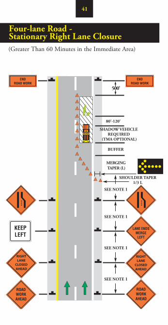
Four-lane Road - Stationary Right Lane Closure(Greater Than 60 Minutes in the Immediate Area)
80'-120'
SEE NOTE 1
SEE NOTE 1
MERGING TAPER (L)
500'
BUFFER
SHADOW VEHICLE REQUIRED
(TMA OPTIONAL)
SHOULDER TAPER1/3 L
SEE NOTE 1
SEE NOTE 1
RIGHTLANE
CLOSEDAHEAD
RIGHTLANE
CLOSEDAHEAD

42
Four-lane Road - Stationary Right Lane Closure
Notes:
1. Sign spacing: Limited Access highway 1300' - 1500'; posted speed greater than 45 mph 500' – 800'; posted speed 45 mph or less 350' – 500'; see spacing of signs for urban use on page 6.
2. For the length of the shoulder taper (1/3 L) and merging taper (L), see Taper Length Chart on page 18.
3. For length of the buffer space, see Buffer Space Length Chart on page 17.
4. A shadow vehicle with at least one amber high intensity rotating, oscillating, or flashing light shall be parked 80'-120' in advance of the first work crew. When posted speed limit is 45 mph or greater, a TMA shall be used.
5. The flashing arrow board shall be a Type C only.
6. For channelizing device spacing, see Spacing for Channelizing Chart on page 10.

43
80'-120'
MERGING TAPER (L)
500'
BUFFER
SHOULDER TAPER1/3 L
SEE NOTE 1
SEE NOTE 1
SEE NOTE 1
SEE NOTE 1
SHADOW VEHICLE REQUIRED
(TMA OPTIONAL)
LEFTLANE
CLOSEDAHEAD
LEFTLANE
CLOSEDAHEAD
Four-lane Road - Stationary Left Lane Closure(Greater Than 60 Minutes in the Immediate Area)

44
Four-lane Road - Stationary Left Lane Closure
Notes:
1. Sign spacing: Limited Access highway 1300' - 1500'; posted speed greater than 45 mph 500' – 800'; posted speed 45 mph or less 350' – 500'; see spacing of signs for urban use on page 6.
2. For the length of the shoulder taper (1/3 L) and merging taper (L), see Taper Length Chart on page 18.
3. For length of the buffer space, see Buffer Space Length Chart on page 17.
4. A shadow vehicle with at least one amber high intensity rotating, oscillating, or flashing light shall be parked 80'-120' in advance of the first work crew. When posted speed limit is 45 mph or greater, a TMA shall be used.
5. The flashing arrow board shall be a Type C only.
6. For channelizing device spacing, see Spacing for Channelizing Chart on page 10.

45
CONES AT 20'MAXIMUM SPACING
(OPTIONAL)
500'
500'
BUFFER
100' MIN.
SEE NOTE 3
SEE NOTE 1
SEE NOTE 1
(OPTIONAL)
BUFFER
100' MIN.
SEE NOTE 3
SEE NOTE 1
SEE NOTE 1
CENTERLANE
CLOSEDAHEAD
CENTERLANE
CLOSEDAHEAD
Center Turn Lane Closure on a Three-lane, Two-way Road(Greater Than 60 Minutes in the Immediate Area)
46
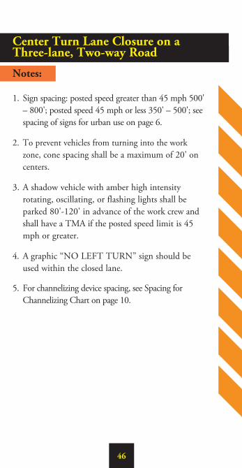
Center Turn Lane Closure on a Three-lane, Two-way Road
Notes:
1. Sign spacing: posted speed greater than 45 mph 500' – 800'; posted speed 45 mph or less 350' – 500'; see spacing of signs for urban use on page 6.
2. To prevent vehicles from turning into the work zone, cone spacing shall be a maximum of 20' on centers.
3. A shadow vehicle with amber high intensity rotating, oscillating, or flashing lights shall be parked 80'-120' in advance of the work crew and shall have a TMA if the posted speed limit is 45 mph or greater.
4. A graphic “NO LEFT TURN” sign should be used within the closed lane.
5. For channelizing device spacing, see Spacing for Channelizing Chart on page 10.

47
SEE NOTE 1
SEE NOTE 1
SEE NOTE 4
SEE NOTE 1
SEE NOTE 1
100' MIN.
BUFFER
LANE SHIFT TAPER
LANE SHIFT TAPER
BUFFER
SEE NOTE 1
500'
500'
100' MIN.
CENTERLANE
CLOSEDAHEAD
CENTERLANE
CLOSEDAHEAD
CONES AT 20'MAXIMUM SPACING
Lane Shift on a Three-lane, Two-way Road(Greater Than 60 Minutes in the Immediate Area)

48
Lane Shift on a Three-lane, Two-way Road
Notes:
1. Sign spacing: posted speed greater than 45 mph 500' – 800'; posted speed 45 mph or less 350' – 500'; see spacing of signs for urban use on page 6.
2. For the length of the lane shift taper, see Taper Length Chart on page 18.
3. For length of the buffer, see Buffer Space Length Chart on page 17.
4. A shadow vehicle with amber high intensity rotating, oscillating, strobe, or flashing lights shall be parked 80'-120' in advance of the work crew and shall have a TMA if the posted speed limit is 45 mph or greater.
5. A graphic “NO LEFT TURN” sign should be used within the closed lane.
6. The two graphic reverse curve/lane shift signs may be replace by a single double reverse curve sign (W24-1) if the distance between the single reverse curve signs is less than 600 feet.
7. Additional channelizing devices for motorist guidance.
8. For channelizing device spacing, see Spacing for Channelizing Chart on page 10.
49
SHADOW VEHICLE REQUIRED
(TMA OPTIONAL)
SEE NOTE 2
84” x 36”
SEE NOTE 2
120' MIN
WORK VEHICLE
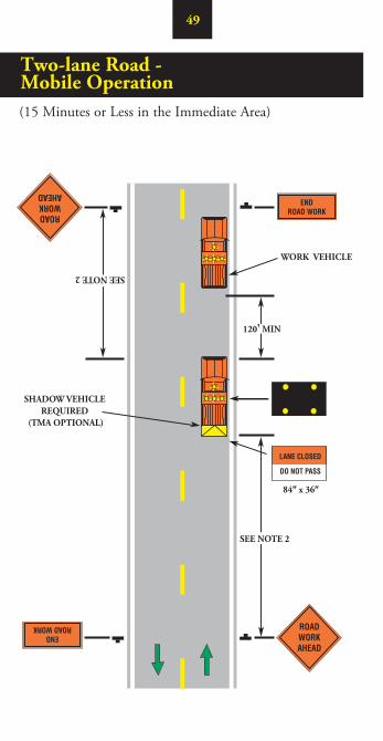
Two-lane Road - Mobile Operation(15 Minutes or Less in the Immediate Area)
50
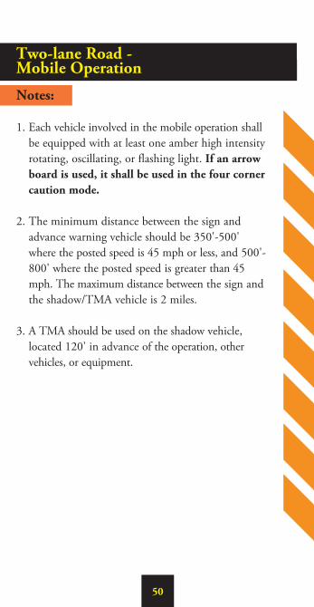
Two-lane Road - Mobile Operation
Notes:
1. Each vehicle involved in the mobile operation shall be equipped with at least one amber high intensity rotating, oscillating, or flashing light. If an arrow board is used, it shall be used in the four corner caution mode.
2. The minimum distance between the sign and advance warning vehicle should be 350'-500' where the posted speed is 45 mph or less, and 500'-800' where the posted speed is greater than 45 mph. The maximum distance between the sign and the shadow/TMA vehicle is 2 miles.
3. A TMA should be used on the shadow vehicle, located 120' in advance of the operation, other vehicles, or equipment.

51
SEE NOTE 1
SEE NOTE 1
SEE NOTE 1
SEE NOTE 2FOR
MAXIMUM WORK ZONE
LENGTH
SEE NOTE 7
500'
500'
MO
WIN
GA
HEA
D
Two-lane Road - Mowing With Encroachment

52
Two-lane Road - Mowing With Encroachment
Notes:
1. Sign spacing: posted speed greater than 45 mph 500' – 800'; posted speed 45 mph or less 350' – 500'; see spacing of signs for urban use on page 6.
2. No more than 2 complete setups (2 miles each) should be exposed to motorist at any one time.
3. Each vehicle involved in the operation shall be equipped with at least one amber high intensity rotating, oscillating, or flashing light.
4. Additional traffic control devices may be required as directed by the VDOT District Traffic Engineer.
5. If the operation is completely off the travelway, the “WATCH FOR SLOW MOVING VEHICLES” sign may be omitted.
6. Connecting roads entering into the work area shall be signed as shown.
7. All vehicles traveling at speeds below 25 mph shall display a slow moving vehicle emblem per OHSA regulation 1910.145(d)(10).
53
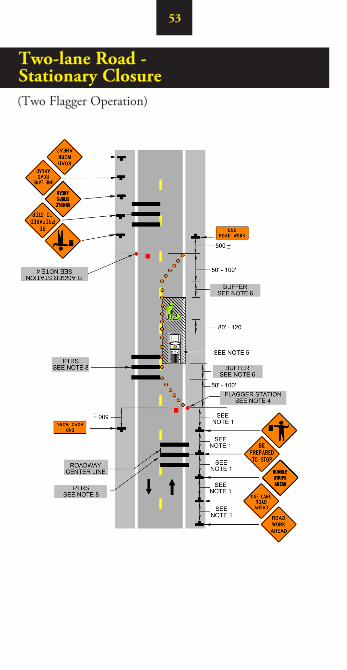
Two-lane Road - Stationary Closure(Two Flagger Operation)

54
Two-lane Road - Stationary Closure
Notes:
1. Sign spacing: posted speed greater than 45 mph 500’ – 800’; posted speed 45 mph or less 350’ – 500’; see spacing of signs for urban use on page 6.
2. The cone transition length should be 50’- 100’ in length.
3. All flaggers shall be state certified and have their certification card in their possession when flagging.
4. Flagging stations should be located with a desired clear site distance in advance of the flagger based on the maximum sign spacing listed in Note 1.
5. A shadow vehicle with at least one amber high intensity rotating, oscillating, or flashing light shall be parked 80’-120’ in advance of the first work crew.
6. For length of the buffer, see Buffer Space Length Chart on page 17.
7. For channelizing device spacing, see Spacing for Channelizing Chart on page 10.
8. For PTRS Spacing see PTRS Placement Chart on page 14.
55
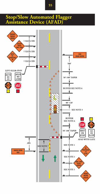
Stop/Slow Automated Flagger Assistance Device (AFAD)
SEE NOTE 5
AFAD WITH GATE
AFAD WITH GATE
500'
80'-120'
SEE NOTE 1
SEE NOTE 1
SEE NOTE 1
SEE NOTE 1
SEE NOTE 1
500'
50'-100' TAPER
50'-100' TAPER
BUFFER SEE NOTE 6
BUFFERSEE NOTE 6
SEE NOTE 1SEE NOTE 7
WAITON
STOP
WAITON
STOP
GOON
SLOW
GOON
SLOW

56
Stop/Slow Automated Flagger Assistance Device (AFAD)
Notes:
1. 1. Sign spacing: posted speed greater than 45 mph 500’ – 800’; posted speed 45 mph or less 350’ – 500’; see spacing of signs for urban use on page 6.
2. The cone transition length should be 50’- 100’ in length.
3. All AFADs shall be operated by state certified flaggers, with their certification card in their possession, and trained in the operation of the AFAD when flagging.
4. AFAD stations should be located with a desired clear site distance in advance of the flagger based on the maximum sign spacing listed in Note 1.
5. A shadow vehicle with at least one amber high intensity rotating, oscillating, strobe, or flashing light shall be parked 80’-120’ in advance of the first work crew.
6. For length of the buffer, see Buffer Space Length Chart on page 17.
7. 4 Additional channelizing devices for motorist guidance.
8. For channelizing device spacing, see Spacing for Channelizing Chart on page 10.

57
Red/Yellow Lens Automated Flagger Assistance Device (AFAD)
SEE NOTE 5
AFAD WITH GATE
FLAGGER STATION
500'
80'-120'
SEE NOTE 1
SEE NOTE 1
SEE NOTE 1
500'
50'-100' TAPER
50'-100' TAPER
BUFFER SEE NOTE 6
BUFFERSEE NOTE 6
SEE NOTE 1SEE NOTE 7
SEE NOTE 1
SEE NOTE 1
STOP
REDHERE ON
SEE NOTE 1

58
Red/Yellow Lens Automated Flagger Assistance Device (AFAD)
Notes:
1. Sign spacing: posted speed greater than 45 mph 500’ – 800’; posted speed 45 mph or less 350’ – 500’; see spacing of signs for urban use on page 6.
2. The cone transition length should be 50’- 100’ in length.
3. All AFADs shall be operated by state certified flaggers, with their certification card in their possession, and trained in the operation of the AFAD when flagging.
4. AFAD stations should be located with a desired clear site distance in advance of the flagger based on the maximum sign spacing listed in Note 1.
5. A shadow vehicle with at least one amber high intensity rotating, oscillating, strobe, or flashing light shall be parked 80’-120’ in advance of the first work crew.
6. For length of the buffer, see Buffer Space Length Chart on page 17.
7. 4 Additional channelizing devices for motorist guidance.
8. For channelizing device spacing, see Spacing for Channelizing Chart on page 10.
59
BUFFER SEE NOTE 4
BUFFER SEE NOTE 4
500'
500'
SEE NOTE 1
SEE NOTE 1
SEE NOTE 1
SEE NOTE 1
SEE NOTE 1
SEE NOTE 1
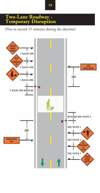
Two-Lane Roadway - Temporary Disruption(Not to exceed 15 minutes during the daytime)

60
Two-Lane Roadway - Temporary Disruption
Notes:
1. Sign spacing: posted speed greater than 45 mph 500' – 800'; posted speed 45 mph or less 350' – 500'; see spacing of signs for urban use on page 6.
2. This application is intended for a planned temporary closure not to exceed 15 minutes
during the daytime.
3. All flaggers shall be state certified and have their certification card in their possession when flagging.
4. For length of buffer, see Buffer Space Chart on page 17.
5. For high volume roads, use of police for traffic stoppage is recommended.
6. Additional traffic control devices may be required.

61
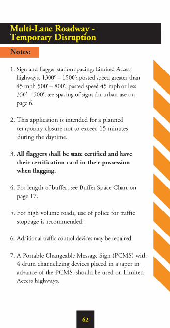
Multi-Lane Roadway - Temporary Disruption
500'
SEE NOTE 1
1 MILE +
SEE NOTE 1
SEE NOTE 1
FORLAYOUT
SEE LOWER RIGHT
BUFFER
FLAGGINGSTATION
PCMS
(Not to exceed 15 minutes during the daytime)
62
Multi-Lane Roadway - Temporary Disruption
Notes:
1. Sign and flagger station spacing: Limited Access highways, 1300’ – 1500’; posted speed greater than 45 mph 500’ – 800’; posted speed 45 mph or less 350’ – 500’; see spacing of signs for urban use on page 6.
2. This application is intended for a planned temporary closure not to exceed 15 minutes
during the daytime.
3. All flaggers shall be state certified and have their certification card in their possession when flagging.
4. For length of buffer, see Buffer Space Chart on page 17.
5. For high volume roads, use of police for traffic stoppage is recommended.
6. Additional traffic control devices may be required.
7. A Portable Changeable Message Sign (PCMS) with 4 drum channelizing devices placed in a taper in advance of the PCMS, should be used on Limited Access highways.
63
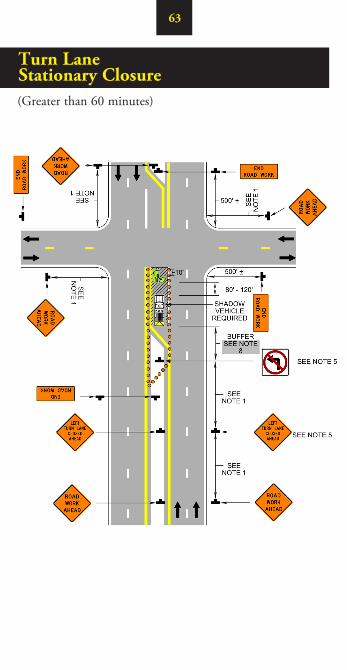
Turn Lane Stationary Closure(Greater than 60 minutes)

64
Turn Lane Stationary Closure
Notes:
1. Sign spacing: posted speed greater than 45 mph 500' – 800'; posted speed 45 mph or less 350' – 500'; see spacing of signs for urban use on page 6.
2. On divided roadways having a median wider than 8', left and right sign assemblies shall be required.
3. To prevent accidental intrusion into the work area, cone spacing shall not exceed 10' on centers.
4. This layout may be used for either left or right turn lane closures.
5. For high turning volumes, additional signing may be required.
6. When closing one turn lane in a dual turn lane situation the left/right turn lane closed ahead and no left turn signs are not required.]
7. For channelizing device spacing, see Spacing for Channelizing Chart on page 10.
8. For length of buffer, see Buffer Space Chart on page 17.
65
500'
500'
500'FOR SIGN LAYOUT SEE UPPER RIGHT
QUADRANT
500'
50'-100'
SEE NOTE 4
SEE
NO
TE
4
SEE
NO
TE
2
SEE
NO
TE
2
SEE NOTE 2
SEE NOTE 2
SEE NOTE 2
SEE NOTE 2
BUFFER SEE NOTE 6
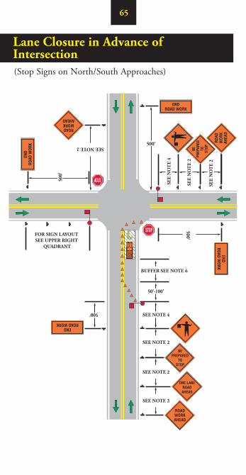
Lane Closure in Advance of Intersection (Stop Signs on North/South Approaches)
66
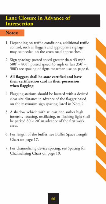
Lane Closure in Advance of Intersection Notes:
1. Depending on traffic conditions, additional traffic control, such as flaggers and appropriate signage, may be needed on the cross road approaches.
2. Sign spacing: posted speed greater than 45 mph 500' – 800'; posted speed 45 mph or less 350' – 500'; see spacing of signs for urban use on page 6.
3. All flaggers shall be state certified and have their certification card in their possession when flagging.
4. Flagging stations should be located with a desired clear site distance in advance of the flagger based on the maximum sign spacing listed in Note 2.
5. A shadow vehicle with at least one amber high intensity rotating, oscillating, or flashing light shall be parked 80'-120' in advance of the first work crew.
6. For length of the buffer, see Buffer Space Length Chart on page 17.
7. For channelizing device spacing, see Spacing for Channelizing Chart on page 10.
67
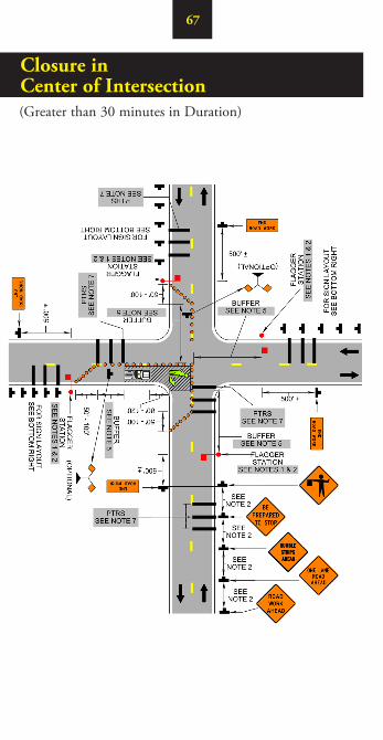
Closure in Center of Intersection(Greater than 30 minutes in Duration)

68
Closure in Center of Intersection
Notes:
1. The control of traffic through the intersection in order of preference:
A. Obtain the services of law enforcement personnel. B. Detour the effective routes to other roads as
approved and directed by the VDOT District Traffic Engineer.
C. Use state certified flaggers on each leg of the intersection as shown.
Appropriate signing, as shown, should be used for law enforcement and flagging operations. See TTC-30 in the Virginia Work Area Protection Manual. 2. Sign spacing: posted speed greater than 45 mph
500' – 800'; posted speed 45 mph or less 350' – 500'; see spacing of signs for urban use on page 6.
3. Cone spacing shall be on 20' spacing or less.
4. For emergency situations of 30 minutes or less duration, appropriate warning and hazard lights on the vehicle and visible for 360º, will be required in addition to channelizing devices around the vehicle.
5. For length of the buffer space, see Buffer Space Length Chart on page 17.
6. For channelizing device spacing, see Spacing for Channelizing Chart on page 10.
7. For PTRS Spacing see PTRS Placement Chart on page 14.
69
10' MINIMUM
500'
SEE NOTE 3
SEE NOTE 5
1/3 L
SEE NOTE 4
SEE NOTE 1
SEE NOTE 1
80'-120'
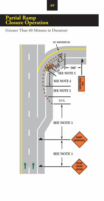
Partial Ramp Closure Operation(Greater Than 60 Minutes in Duration)

70
Partial Ramp Closure Operation
Notes:
1. Sign spacing: limited access 1300' - 1500'; posted speed greater than 45 mph 500' – 800'; posted speed 45 mph or less 350' – 500'; see spacing of signs for urban use on page 6.
2. To prevent accidental intrusion into the work area, cone spacing shall not exceed 20' on centers.
3. Cone Taper Length (L) = actual speed of motorists (S) x width of actual ramp closure (W). [L = S x W] (Example: 270' = 45 x 6).
4. For length of the buffer space, see Buffer Space Length Chart on page 17.
5. A shadow vehicle with at least one amber high intensity rotating, oscillating, or flashing light shall be parked 80'-120' in advance of the first work crew. When posted speed limit is 45 mph or greater, a TMA shall be used.
6. Truck off-tracking should be considered when determining whether the 10 foot minimum lane width is adequate.
7. For channelizing device spacing, see Spacing for Channelizing Chart on page 10.
71
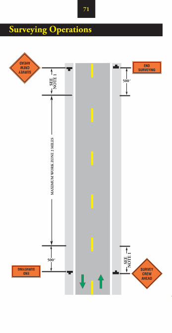
Surveying Operations
SEE
NO
TE
1
SEE
NO
TE
1
MA
XIM
UM
WO
RK
ZO
NE
2 M
ILES
500’
500’

72
Surveying Operations
Notes:
1. Sign spacing distance should be 350'-500' where the posted speed is 45 mph or less, and 500'-800' where the posted speed is greater than 45 mph.
2. Each vehicle involved in the surveying operations shall have at least one amber high intensity rotating, oscillating, or flashing light.
3. Maximum length of the work space is two miles.
4. Surveying operations shall be off the travelway. For encroachment into the travelway, see flagging or lane closure traffic control.

73
Flagging Procedures
Traffic Proceed
Alert and Slow
Traffic
Stop Traffic
Paddle
Notes:
1. To maintain alertness, flaggers should be relieved every two hours for a minimum period of fifteen minutes.
74
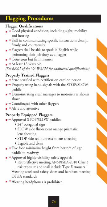
Flagging ProceduresFlagger Qualifications Good physical condition, including sight, mobility
and hearing Skill in communicating specific instructions clearly,
firmly and courteously Flaggers shall be able to speak in English while
performing their job duty as a flagger Courteous but firm manner At least 18 years old(See 6E.01 of the VA WAPM for additional qualifications)
Properly Trained Flaggers State certified with certification card on person Properly using hand signals with the STOP/SLOW
paddle Demonstrating clear messages to motorists as shown
above Coordinated with other flaggers Alert and attentive
Properly Equipped Flaggers Approved STOP/SLOW paddles: • 24" octagonal sign • SLOW side fluorescent orange prismatic
lens sheeting • STOP side red fluorescent lens sheeting • Legible and clean Five foot minimum height from bottom of sign
paddle to roadway Approved highly-visibility safety apparel: • Retroreflective meeting ANSI/ISEA-2010 Class 3
risk exposure and shall include Type E trousers Wearing steel toed safety shoes and hardhats meeting
OSHA standards Wearing headphones is prohibited

75
Flagging Procedures (continued)
Proper Flagging Stations Good approach sight distance based to the chart below Highly visible to traffic Positioned away from the work space
according to chart below Beginning operation from the roadway shoulder Never standing in the moving traffic lane Standing and flagging alone Illuminated at night by a light source producing a mini-
mum of 5 foot candles (50 lux)
Proper Advance Warning Signs Always use correct warning signs, in proper order Allow reaction distance from signs to work area Always remove flagging symbol sign when not at the
flagging station
Flagger Station Distance in Advance of the Work SpaceThe distance from the flagger station to the work space should be as shown in the table below plus the 50 to 100 foot one-lane, two-way taper length.
Posted Speed (MPH) Distance (Feet)
20 and below 115 – 120
25 155 – 165
30 200 – 210
35 250 – 260
40 305 – 325
45 360 – 380
50 425 – 445
55 500 – 530
76
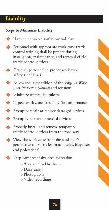
Liability
Steps to Minimize Liability
Have an approved traffic control plan
Personnel with appropriate work zone traffic control training shall be present during installation, maintenance, and removal of the traffic control devices
Train all personnel in proper work zone safety techniques
Follow the latest edition of the Virginia Work Area Protection Manual and revisions
Minimize traffic disruptions
Inspect work zone sites daily for conformance
Promptly repair or replace damaged devices
Promptly remove unneeded devices
Properly install and remove temporary traffic control devices from the road way
View the work zone from the road user’s perspective (cars, trucks, motorcycles, bicyclists, and pedestrians)
Keep comprehensive documentation o Written checklist form o Daily diary o Photographs o Video recordings
77
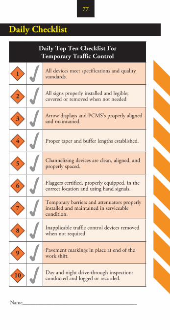
Daily Checklist
Name____________________________________________
Daily Top Ten Checklist For Temporary Traffic Control
1 All devices meet specifications and quality standards.
2 All signs properly installed and legible; covered or removed when not needed
3 Arrow displays and PCMS’s properly aligned and maintained.
4 Proper taper and buffer lengths established.
5 Channelizing devices are clean, aligned, and properly spaced.
6 Flaggers certified, properly equipped, in the correct location and using hand signals.
7Temporary barriers and attenuators properly installed and maintained in serviceable condition.
8 Inapplicable traffic control devices removed when not required.
9 Pavement markings in place at end of the work shift.
10 Day and night drive-through inspections conducted and logged or recorded.

78
Intersection Sight Distance(ISD)- Feet
Posted Speed (mph) Minimum ISD
20 225
25 280
30 335
35 390
40 445
45 500
50 555
55 610
60 665
65 720
70 775
Intersection Sight Distance
For a review of all current work zone safety requirements, the Virginia Work Area Protection Manual may be accessed at: www.VirginiaDOT.org. Access the Business Center on the VDOT Home Page and click on “Manuals” to open the web page containing the link to the latest edition of the Virginia Work Area Protection Manual.

AcknowledgementsThese guidelines were developed by the Virginia Department of Transportation to meet VDOT’s requirements for safety in temporary traffic control zones. For additional information related to these work zone safety guidelines, the Virginia Work Area Protection Manual or work zone safety in Virginia, please contact:
Virginia Department of Transportation Traffic Engineering Division -
Work Zone Safety Section 1401 East Broad Street Richmond, VA 23219 1-800-FOR-ROAD