worcester 24cdibf march 05 installation and servicing ...€¦ · supplied by spares.co tel. 0161...
TRANSCRIPT

Supplied By www.heating spares.co Tel. 0161 620 6677
24CDi BFWALL MOUNTED COMBINATION BOILER FOR CENTRAL HEATING
AND MAINS FED DOMESTIC HOT WATER
INSTALLATION AND
SERVICING INSTRUCTIONS
GC NUMBER 47 311 29
BOILER OUTPUTAutomatic Modulating Control
To Domestic Hot Water and Central HeatingMinimum 9.0 kW
Maximum 24.0 kW
IMPORTANT: THIS APPLIANCE IS FOR USE WITH NATURAL GAS ONLY THESE INSTRUCTIONS APPLY IN THE UK ONLY
THESE INSTRUCTIONS ARE TO BE LEFT WITH THE USER OR AT THE GAS METER
This appliance must be installed by a competent person in accordancewith the Gas Safety (Installation and Use) Regulations 1998
Supplied By www.heating spares.co Tel. 0161 620 6677
1.1 Gas Safety (Installation & Use) Regulations 1996 (Amended1996) : It is the law that all gas appliances are installed by acompetent person in accordance with the above regulations.Failure to install appliances correctly could lead to prosecution. Itis in your interest, and that of safety, to ensure compliance withthe law.1.2 The manufacturers notes must not be taken, in any way, asoverriding statutory obligations.1.3 The compliance with a British Standard or European Normdoes not, of itself, confer immunity from legal obligations.1.4 The installation of the appliance must be in accordance withthe relevant requirements of the Gas Safety Regulations, currentIEE Regulations, Building Regulations, Building Standards(Scotland) and local water bye-laws.1.5 The installation should follow the recommendations of thefollowing British Standards unless otherwise indicated:BS6798 - Specification for the installation of gas fired hot waterboilers of rated input not exceeding 60kW (Gross).BS5449 - Central heating for domestic premises.BS5546:1 - Installation of gas hot water supplies for domesticpurposes.BS5440/1 - Flues and ventilation for gas appliances of rated inputnot exceeding 60kW (Gross): Flues.BS5440/2 - Flues and ventilation for gas appliances of rated inputnot greater than 60kW (Gross): Air supply.BS6891 - Installation of low pressure gas pipework installationsupto 28mm (R1).BS6700 - Domestic water supply in buildings.BS7593 - Water treatment in domestic heating systems.1.6. To ensure that the installation will perform to the higheststandards, the system and components should conform to anyother relevant standards.1.7. The appliance and/or components conform, whereapplicable, with the Essential Requirements of the Gas ApplianceDirective, the Boiler Efficiency Directive, the EMC Directive and theLow Voltage Directive.1.8. In accordance with the requirements of COSSH the appliancedoes not contain any substances which are harmful to health.1.9. Product Liability regulations indicate that, in certaincircumstances, the installer can be held responsible, not only formistakes on his part but also for damage resulting from the use offaulty materials. We advise that, to avoid any risk, only qualityapproved branded fittings are used.1.10. The advice and instructions given in this document covers,as far as possible, the foreseeable situations which may arise.Contact Worcester Heat Systems Technical Department, Telephone:08705 266241, for advice on specific installations.
2.1. General Information2.1.1. The appliance is set to give a maximum output of 24kWto the domestic hot water and to the heating system. The hotwater flow rate is limited to a nominal 9 l/min at a maximumtemperature rise of 40°C.2.1.2. The sanitary water section of the appliance is suitable forwater mains pressures of upto 10bar.2.2 Electrical SupplyMains supply: 230V ~ 50 Hz. 140Watts.External fuse: 3A (BS 1362). Internal fuses: T 2A (F1), and T 1.25A (F2).2.3 Gas SupplyThe boiler requires 2.9m3/h (100ft3/hr) of natural gas (G20) Thegas meter and supply pipes must be capable of supplying thisquantity of gas in addition to the demands of any otherappliances being served. The meter governor or regulator should deliver a dynamicpressure of 20mbar (8in wg) at the appliance, which is about18.5mb at gas valve inlet pressure test point.The complete installation, including the gas meter, must betested for soundness and purged. Refer to BS 6891.2.4 PackingThe appliance and flue components are packed in separate cartons.2.5 InstallationThe appliance is suitable for indoor installations only.An open vent feed pipe assembly kit is available. A wall-spacing frame to allow pipe runs behind the appliance isavailable.An inlet water filter is fitted to the mains cold water inlet on theappliance.The appliance is fitted with a system filling link assembly. SeePage 8The appliance is suitable for connection to a sealed or openvented primary system.The specif ied ventilation openings made into a wall orcompartment door must not be obstructed.If the appliance is to be fitted into a compartment then thecompartment must conform to the requi rements o fBS 5440:2.Do not place anything on top of the appliance.The clearances specified for servicing must be maintained. Refer to Fig. 2.2.6 FlueThe appliance has a room-sealed balanced flue system to therear.
2. General Information1. Installation Regulations
2
11. Electrical ........................................................................ Page 1012. Installation.................................................................... Page 1313. Commissioning ............................................................ Page 1514. Instructions to the User .............................................. Page 1715. Inspection and Servicing ............................................ Page 1816. Replacement of Parts .................................................. Page 1917. Short Parts List ............................................................ Page 2518. Operational Flow Diagrams........................................ Page 2720. Fault Finding ................................................................ Page 29
1. Installation Regulations .............................................. Page 22. General Information .................................................... Page 23. Technical Data .............................................................. Page 44. Siting the Appliance .................................................... Page 65. Siting the Flue Terminal .............................................. Page 76. Air Supply .................................................................... Page 77. Sealed Primary Systems ............................................ Page 88. Gas Supply.................................................................... Page 89. Open Vent Primary Systems ...................................... Page 910. Domestic Hot Water .................................................... Page 9
Contents

Supplied By www.heating spares.co Tel. 0161 620 6677
The standard flue assembly length is from 225mm to 420mm.An extension flue length from 420mm to 560mm is available.A terminal guard, Type GC 393 545, is available from Tower FlueComponents, Vale Rise, Tonbridge, TN9 1TB.Do not allow the flue terminal fitted to the outside wall tobecome obstructed or damaged.2.7 ControlsThe ON/OFF switch will turn the mains electricity on and off atthe appliance.The electronic control system and gas valve modulate the heatinput in response to the central heating and domestic hot watertemperature settings. The Central Heating Temperature control knob provides for theselection of domestic hot water only (turned fully anti-clockwise)or central heating and domestic hot water (turned clockwise).The position of the Domestic Hot Water control knob willdetermine the temperature of the water delivered to the tap orshower or bath. A facia mounted programmer is available as an optional extra. Aremote mounted programmer may be connected to theappliance.The integral facia displays indicate the status of the appliance.There is provision for the connection of a mains voltage roomthermostat and/or a frost thermostat.The electronic controls prevent rapid cycling of the appliance inthe central heating mode.2.8 System NotesIMPORTANTCheck that no dirt is left in either the gas or water pipeworkas this could cause damage to the appliance. Thoroughlyflush the heating system and the cold water mains supply inaccordance with the recommendations of BS7593: 1992.The water pipe connections throughout a sealed system must becapable of sustaining a pressure of up to 3 bar.Radiator valves must conform to the requirements of BS 2767:1991.The relief valve discharge must be directed away from any electricalcomponents or where it would cause a hazard to the user.A drain cock to BS 2879 must be fitted to the lowest point of thesystem.For circuit design purposes it is important that due note is taken ofthe information given in Table 3 relating to the available pump head.2.9 Showers, Bidets, Taps and Mixing ValvesHot and cold taps and mixing valves used in the system must besuitable for operating at the mains pressure.Thermostatically controlled shower valves will guard against theflow of water at too high a temperature.If a pressure equalising valve is used, set the Domestic Hot Watertemperature control knob to the ‘MAX’ position.Hot and cold mains fed water can be supplied direct to an over-rim flushing bidet subject to local Water Company requirements.With all mains fed systems the flow of water from the individualtaps wil l vary with the number of outlets operatedsimultaneously and the cold water mains supply pressure to theproperty. Flow balancing using ‘Ball-o-Fix’ type valves isrecommended to avoid an excessive reduction in flow toindividual outlets. For further information contact WorcesterHeat Systems Technical Helpline.2.10 Safety ConsiderationsThe appliance must not be operated in a waterless condition.The appliance must not be operated with the boiler inner casingcover removed.Work must not be carried out on the appliance without the gasand electricity supplies being switched off.Checks must be made to ensure that, where applicable, theventilation openings made into walls and partitions are of thecorrect size and are not obstructed.
IMPORTANT: Where back-flow prevention devices, includingwater meters, are fitted the expansion of hot water into coldwater main can be prevented. This can result in a pressurebuild-up that may cause damage to the boiler and householddevices such as showers, washing machines etc.In these cases we recommend that a mini-expansion vesselbe fitted adjacent to the boiler in the cold water pipe.2.11 OperationDomestic Hot Water: With a demand for hot water the burnerwill light at its maximum setting and then automatically adjustits output to maintain the temperature of the delivered water.When hot water is no longer required, the burner will extinguish.The fan and pump may continue to run for a short period todissipate the residual heat from the appliance.Central Heating: With a demand for heating the burner will lightat its minimum setting and gradually increase to give themaximum output. The output of the appliance is thenautomatically adjusted to maintain the temperature of thesystem. The output can reduce down to a minimum of 11.9 kW.If the system no longer requires even the minimum output tomaintain the desired room temperature the burner willextinguish. The fan and pump may continue to run to dissipatethe residual heat from the appliance. The appliance will remainoff for a fixed period of three minutes before re-lighting toautomatically meet the system requirements.Domestic Hot Water and Central Heating: The appliance willsupply heat to the central heating system as required. A demandfor domestic hot water at a tap or shower will override thecentral heating requirement for the period of the domestic hotwater demand. When hot water is no longer required theappliance will return to the central heating state and its normalmode of operation.
3
Fig. 1. Appliance water flow diagram.
Boiler
1
2
3
4
5
6 7 8 9 10
11
12
13
1. Automatic airvent.
2. Gas to waterheat exchanger.
3. Circulatingpump.
4. Water to waterheatexchanger.
5. Waterdivertingvalve.
6. CH flow.
7. DHW out.
8. Mains cold water in.
9. CH return
10.Safety discharge.
11.Central heatingby-pass adjustment.
12.Pressure reliefvalve.
13.Sealed systemexpansionvessel.

Supplied By www.heating spares.co Tel. 0161 620 6677
NOMINAL BOILER RATINGS (10 Minutes After Lighting)
BOILER ADJUSTED FOR G20 (Natural Gas)
OUTPUT INPUT (Net)BURNER SETTING
GAS RATEPRESSUREkW Btu/h kW Btu/h m bar. in. wg. m3/h ft3/h9.0 30,700 10.4 35,500 1.8 0.8 1.1 37.28
11.9 40,600 13.8 47,100 3.5 1.4 1.46 51.524.0 81,900 27.0 92,400 13.2 5.3 2.9 100.0
4
Table 1.
FLUE DETAILS
HORIZONTAL FLUE mm inches
WALL HOLE WIDTH 365 14.4
HEIGHT 265 10.5
STANDARD FLUE MINIMUM LENGTH 225 8.9
MAXIMUM LENGTH 420 16.5
EXTENDED FLUE MAXIMUM LENGTH 560 22
Table 2.
PUMP HEAD
BOILER OUTPUT HEAD MIN. FLOW RATE FLOW/ RETURNDIFFERENTIAL
kW Btu/h Metres Feet L/min. Gal/Min. °C °F
9.0 30,700 4.8 15.7 11.7 2.57 11°C 20°F
24.0 81,900 2.0 6.6 20.5 4.5 12.5°C 22°F
Table 3
MECHANICAL SPECIFICATIONSCENTRAL HEATING FLOW - COMPRESSION 22mm
CENTRAL HEATING RETURN - COMPRESSION 22mm
COLD WATER INLET - COMPRESSION 15mm
DOMESTIC HOT WATER FLOW - COMPRESSION 15mm
GAS INLET Rp 3⁄4
RELIEF VALVE DISCHARGE - COMPRESSION 15mm
CASING HEIGHT 850mm
CASING WIDTH 450mm
CASING DEPTH 360mm
WEIGHT - DRY 45kg
WEIGHT - MAXIMUM INSTALLATION 42kg
WEIGHT - PACKAGED 48kg
Table 4
3. Technical Data
Note: Gross Heat Input x 0.901= Net Heat Input.
DHW
CHMAX
Supplied By www.heating spares.co Tel. 0161 620 6677
5
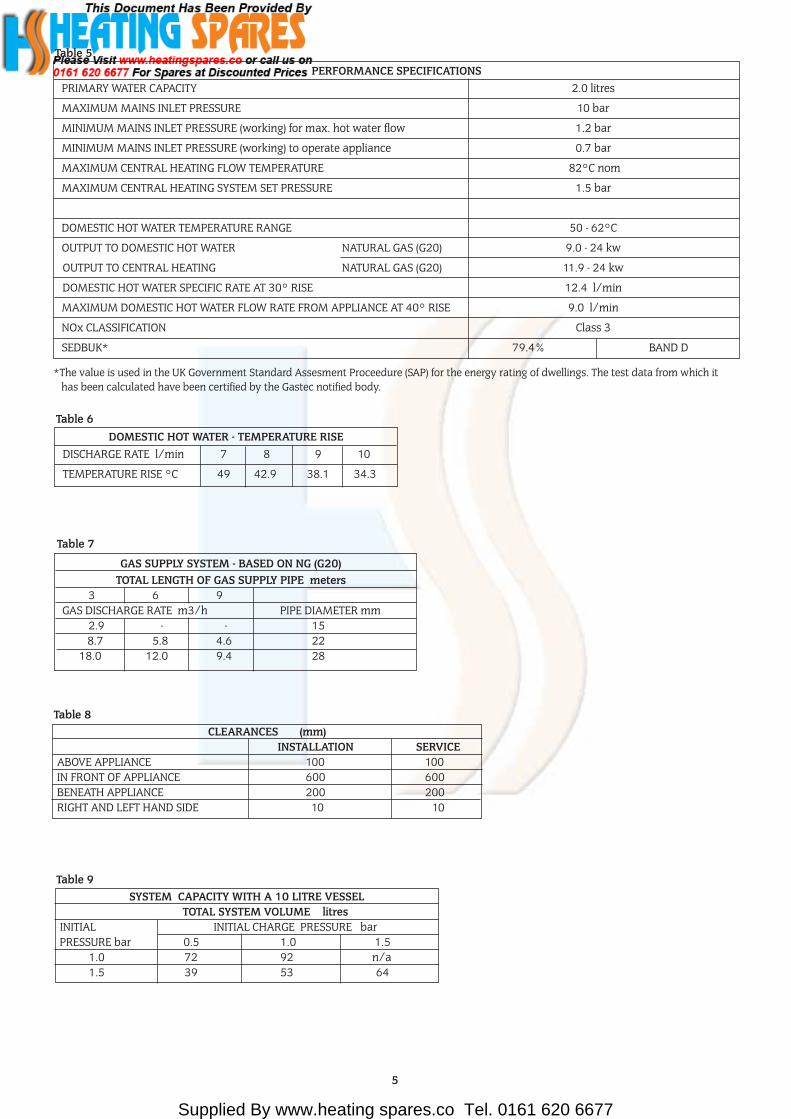
PERFORMANCE SPECIFICATIONSPRIMARY WATER CAPACITY 2.0 litres
MAXIMUM MAINS INLET PRESSURE 10 bar
MINIMUM MAINS INLET PRESSURE (working) for max. hot water flow 1.2 bar
MINIMUM MAINS INLET PRESSURE (working) to operate appliance 0.7 bar
MAXIMUM CENTRAL HEATING FLOW TEMPERATURE 82°C nom
MAXIMUM CENTRAL HEATING SYSTEM SET PRESSURE 1.5 bar
DOMESTIC HOT WATER TEMPERATURE RANGE 50 - 62°C
OUTPUT TO DOMESTIC HOT WATER NATURAL GAS (G20) 9.0 - 24 kw
OUTPUT TO CENTRAL HEATING NATURAL GAS (G20) 11.9 - 24 kw
DOMESTIC HOT WATER SPECIFIC RATE AT 30° RISE 12.4 l/min
MAXIMUM DOMESTIC HOT WATER FLOW RATE FROM APPLIANCE AT 40° RISE 9.0 l/min
NOx CLASSIFICATION Class 3
SEDBUK* 79.4% BAND D
Table 5
DOMESTIC HOT WATER - TEMPERATURE RISEDISCHARGE RATE l/min 7 8 9 10
TEMPERATURE RISE °C 49 42.9 38.1 34.3
Table 6
GAS SUPPLY SYSTEM - BASED ON NG (G20)TOTAL LENGTH OF GAS SUPPLY PIPE meters
3 6 9GAS DISCHARGE RATE m3/h PIPE DIAMETER mm
2.9 - - 158.7 5.8 4.6 22
18.0 12.0 9.4 28
Table 7
CLEARANCES (mm)INSTALLATION SERVICE
ABOVE APPLIANCE 100 100IN FRONT OF APPLIANCE 600 600BENEATH APPLIANCE 200 200RIGHT AND LEFT HAND SIDE 10 10
Table 8
SYSTEM CAPACITY WITH A 10 LITRE VESSELTOTAL SYSTEM VOLUME litres
INITIAL INITIAL CHARGE PRESSURE barPRESSURE bar 0.5 1.0 1.5
1.0 72 92 n/a1.5 39 53 64
Table 9
*The value is used in the UK Government Standard Assesment Proceedure (SAP) for the energy rating of dwellings. The test data from which ithas been calculated have been certified by the Gastec notified body.
Supplied By www.heating spares.co Tel. 0161 620 6677
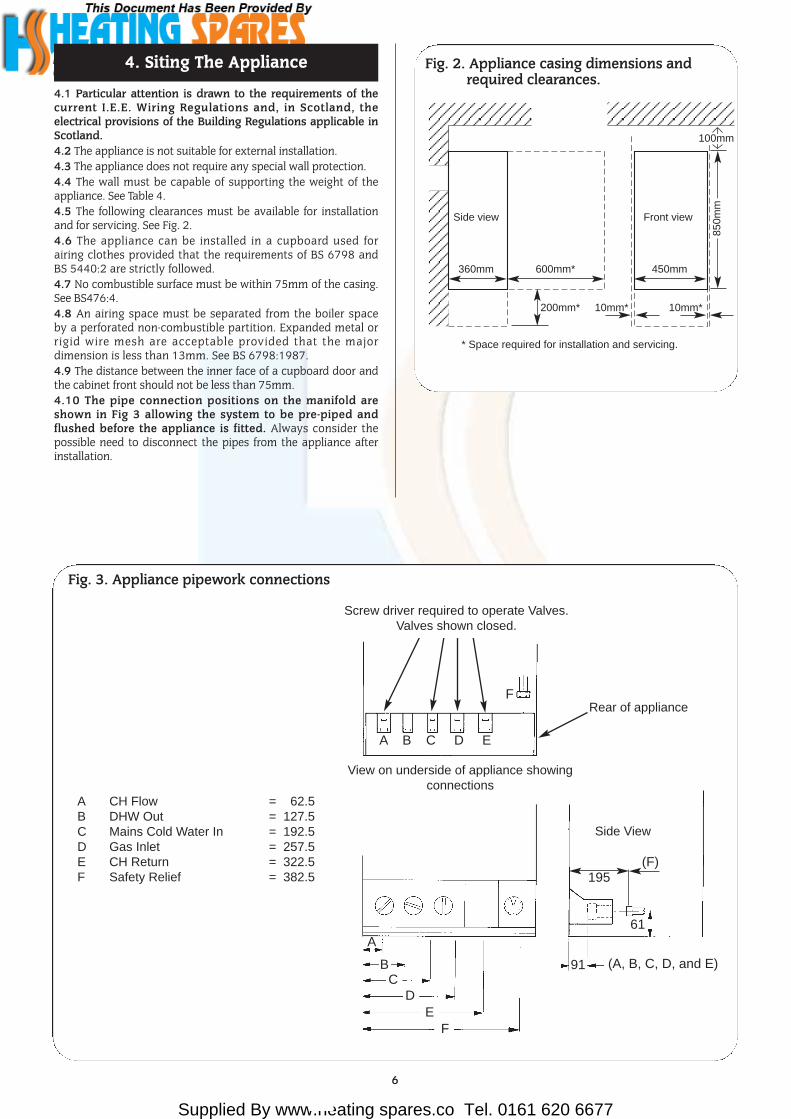
4.1 Particular attention is drawn to the requirements of thecurrent I.E.E. Wiring Regulations and, in Scotland, theelectrical provisions of the Building Regulations applicable inScotland.4.2 The appliance is not suitable for external installation.4.3 The appliance does not require any special wall protection.4.4 The wall must be capable of supporting the weight of theappliance. See Table 4.4.5 The following clearances must be available for installationand for servicing. See Fig. 2.4.6 The appliance can be installed in a cupboard used forairing clothes provided that the requirements of BS 6798 andBS 5440:2 are strictly followed.4.7 No combustible surface must be within 75mm of the casing.See BS476:4.4.8 An airing space must be separated from the boiler spaceby a perforated non-combustible partition. Expanded metal orrigid wire mesh are acceptable provided that the majordimension is less than 13mm. See BS 6798:1987.4.9 The distance between the inner face of a cupboard door andthe cabinet front should not be less than 75mm.4.10 The pipe connection positions on the manifold areshown in Fig 3 allowing the system to be pre-piped andflushed before the appliance is fitted. Always consider thepossible need to disconnect the pipes from the appliance afterinstallation.
4. Siting The Appliance
6
Fig. 3. Appliance pipework connections
A
BC
DE
F
91 (A, B, C, D, and E)
61
A B C D E
F
View on underside of appliance showing connections
Rear of appliance
A CH Flow = 62.5B DHW Out = 127.5C Mains Cold Water In = 192.5D Gas Inlet = 257.5E CH Return = 322.5F Safety Relief = 382.5 195
Screw driver required to operate Valves.Valves shown closed.
(F)
Side View
Fig. 2. Appliance casing dimensions andrequired clearances.
Side view
360mm 600mm*
200mm* 10mm*
* Space required for installation and servicing.
Front view
450mm
10mm*
100mm
850m
m

Supplied By www.heating spares.co Tel. 0161 620 6677
L
LK
K
FF
GA
MEJF
HI
D
G
A
B,C
See Fig. 4
5.1 The flue must be installed as specified in BS 5440:Part 1andthe building regulations.NOTE: Installations coming under the jurisdiction of BuildingControl should adhere to the increased clearances.
5.2 The terminal must not cause an obstruction nor thedischarge cause a nuisance.
5.3 If the terminal is fitted within 1000mm of a plastic or paintedgutter or within 500mm of painted eaves then an aluminiumshield at least 1000mm long should be fitted to the underside ofthe gutter or painted surface.
5.4 If a terminal is fitted less than 2 metres above a surface towhich people have access then a guard must be fitted. SeeSection 2.9.
5.5 The terminal guard must be evenly spaced about the flueterminal and fixed to the wall using plated screws.
5.6 In certain weather conditions a terminal may steam andsiting where this could cause a nuisance should be avoided.
5.7 Take care to ensure that combustion products do not enterventilated roof voids.
6.1 Installations in cupboards or compartments requirepermanent vents for cooling purposes, one at high level and oneat low level, either direct to outside air or to a room. Both ventsmust pass to the same room or be on the same wall to outsideair.6.2 Refer to BS 6798 and BS 5440:2 for additional information.6.3 There must be sufficient clearance around the appliance toallow proper circulation of ventilation air. The clearancesrequired for Installation and Servicing will normally be adequatefor ventilation. 6.4 The minimum free areas required are given below.
6.5 Refer to BS 6798 and BS 5440:2 for additional information.
6. Air Supply5. Siting The Flue Terminal
7
POSITION OF AIR FROM AIR DIRECTAIR VENTS THE ROOM FROM OUTSIDE
HIGH LEVEL 270 cm2 135 cm2
LOW LEVEL 270 cm2 135 cm2
TERMINAL POSITION MIN. DISTANCEA– Directly below an opening, air brick,
window etc. 1500mm A1– Above an opening, air brick,
window etc. 300mm A2– Horizontaly to an opening, air brick,
window etc. 600mm B– Below gutters, soil pipes or drain pipes. 300 mm C– Below eaves. 300 mm D– Below balconies or car port roof. 600 mm E– From vertical drain pipes and soil pipes. 75 mm F– From internal or external corners. 600 mm
Fig. 4. Siting of the flue terminal.
TERMINAL POSITION MIN. DISTANCEG– Above ground, roof or balcony level. 300 mm H– From a surface facing a terminal. 600 mm I– From a terminal facing a terminal 600 mm J– From an opening in a car port (e.g. door
window) into dwelling. 1200 mm K– Vertically from a terminal on the same
wall. 1500 mm L– Horizontally from a terminal on the same
wall. 300 mm
A1
A2

Supplied By www.heating spares.co Tel. 0161 620 6677
See Figs. 5, 6 and 6a7.1 The system must comply with the requirements of BS 6798and BS 5449.7.2 The appliance must not be operated without the systembeing full of water, properly vented and pressurised.7.3 The pressure relief valve operates at 3 bar (45lb/in2). Thedischarge must be directed away from electrical components orwhere it might be a hazard to the user.7.4 The pressure gauge indicates the system pressure whichmust be maintained.7.5 The 10 litre expansion vessel is charged to 0.5 bar and issuitable for a static head of 5 metres (17.5ft). The pressure can beincreased if the static head is greater than 5 metres (17.5ft).7.6 With an initial system pressure of 0.5 bar, a system capacityof about 72 litres can be accommodated. Refer to BS 7074 formore information. The charge pressure can be increased but witha decrease in system volume.7.7 The appliance includes a system filling link.7.8 Water loss must be replaced.7.9 Repeated venting loses water from the system. It is essentialthat this water is replaced and the system pressure maintained.Refer to Section 13 Commissioning.
7.10 Connections to the mains water supply must not be madewithout the authority of the local Water Company.7.11 The pump is set at maximum and must not be adjusted.7.12 Connections in the system must resist a pressure of upto3bar.7.13 Radiator valves must conform to BS2767:10.7.14 Other valves used should conform to the requirements ofBS1010.7.15 No special system inhibitor is needed.
8.1 The appliance requires 2.9 m3/h of natural gas (G20) . Check that the supply system can accommodate this togetherwith any other appliances connected to it. Refer to Table 7.8.2 A natural gas appliance must be connected to a governedmeter.8.3 There must be a pressure of 20mbar (G20) at the inlet to theappliance. This is equivalent to a pressure of18.5 - 19.0mbar (G20) at the inlet pressure tapping on the gasvalve.
7. Sealed Primary Systems
8
Fig.5. Sealed primary water system.
Lockshieldvalve
Radiatorvalve
Heatingreturn
Hot water out
Expansionvessel
Automaticair vent
Water main
British Standardstop valve.Fixed spindle type
NOTE: A drain cock should be installed atthe lowest point of the heating circuit andbeneath the appliance.
Mains coldwater
Heatingflow
Fig. 6. Filling Loop. Fig. 6a. Filling Key inserted for filling.
Grey fillingknob Always remove key
after filling
Filling Key
8. Gas Supply
Supplied By www.heating spares.co Tel. 0161 620 6677
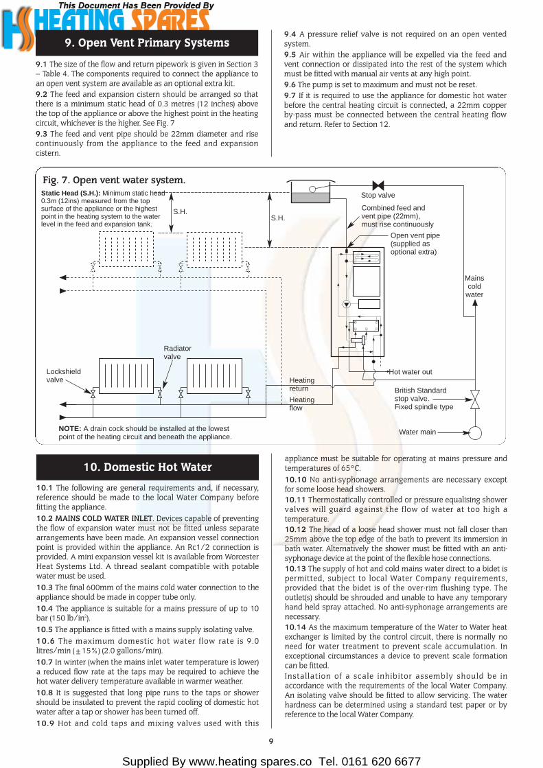
9.1 The size of the flow and return pipework is given in Section 3– Table 4. The components required to connect the appliance toan open vent system are available as an optional extra kit.9.2 The feed and expansion cistern should be arranged so thatthere is a minimum static head of 0.3 metres (12 inches) abovethe top of the appliance or above the highest point in the heatingcircuit, whichever is the higher. See Fig. 79.3 The feed and vent pipe should be 22mm diameter and risecontinuously from the appliance to the feed and expansioncistern.
9.4 A pressure relief valve is not required on an open ventedsystem.9.5 Air within the appliance will be expelled via the feed andvent connection or dissipated into the rest of the system whichmust be fitted with manual air vents at any high point.9.6 The pump is set to maximum and must not be reset.9.7 If it is required to use the appliance for domestic hot waterbefore the central heating circuit is connected, a 22mm copperby-pass must be connected between the central heating flowand return. Refer to Section 12.
9. Open Vent Primary Systems
9
Fig. 7. Open vent water system.
Lockshieldvalve
Radiatorvalve
S.H.S.H.
Heatingreturn
Hot water out
Stop valve
Water main
British Standardstop valve.Fixed spindle type
Combined feed andvent pipe (22mm),must rise continuously
Static Head (S.H.): Minimum static head0.3m (12ins) measured from the topsurface of the appliance or the highestpoint in the heating system to the waterlevel in the feed and expansion tank.
Open vent pipe(supplied asoptional extra)
Mainscold
water
Heatingflow
NOTE: A drain cock should be installed at the lowestpoint of the heating circuit and beneath the appliance.
10.1 The following are general requirements and, if necessary,reference should be made to the local Water Company beforefitting the appliance.10.2 MAINS COLD WATER INLET. Devices capable of preventingthe flow of expansion water must not be fitted unless separatearrangements have been made. An expansion vessel connectionpoint is provided within the appliance. An Rc1/2 connection isprovided. A mini expansion vessel kit is available from WorcesterHeat Systems Ltd. A thread sealant compatible with potablewater must be used.10.3 The final 600mm of the mains cold water connection to theappliance should be made in copper tube only.10.4 The appliance is suitable for a mains pressure of up to 10bar (150 lb/in2).10.5 The appliance is fitted with a mains supply isolating valve.10.6 The maximum domestic hot water flow rate is 9.0litres/min (±15%) (2.0 gallons/min).10.7 In winter (when the mains inlet water temperature is lower)a reduced flow rate at the taps may be required to achieve thehot water delivery temperature available in warmer weather.10.8 It is suggested that long pipe runs to the taps or showershould be insulated to prevent the rapid cooling of domestic hotwater after a tap or shower has been turned off.10.9 Hot and cold taps and mixing valves used with this
appliance must be suitable for operating at mains pressure andtemperatures of 65°C.10.10 No anti-syphonage arrangements are necessary exceptfor some loose head showers. 10.11 Thermostatically controlled or pressure equalising showervalves will guard against the flow of water at too high atemperature.10.12 The head of a loose head shower must not fall closer than25mm above the top edge of the bath to prevent its immersion inbath water. Alternatively the shower must be fitted with an anti-syphonage device at the point of the flexible hose connections.10.13 The supply of hot and cold mains water direct to a bidet ispermitted, subject to local Water Company requirements,provided that the bidet is of the over-rim flushing type. Theoutlet(s) should be shrouded and unable to have any temporaryhand held spray attached. No anti-syphonage arrangements arenecessary.10.14 As the maximum temperature of the Water to Water heatexchanger is limited by the control circuit, there is normally noneed for water treatment to prevent scale accumulation. Inexceptional circumstances a device to prevent scale formationcan be fitted.Installation of a scale inhibitor assembly should be inaccordance with the requirements of the local Water Company.An isolating valve should be fitted to allow servicing. The waterhardness can be determined using a standard test paper or byreference to the local Water Company.
10. Domestic Hot Water
Supplied By www.heating spares.co Tel. 0161 620 6677
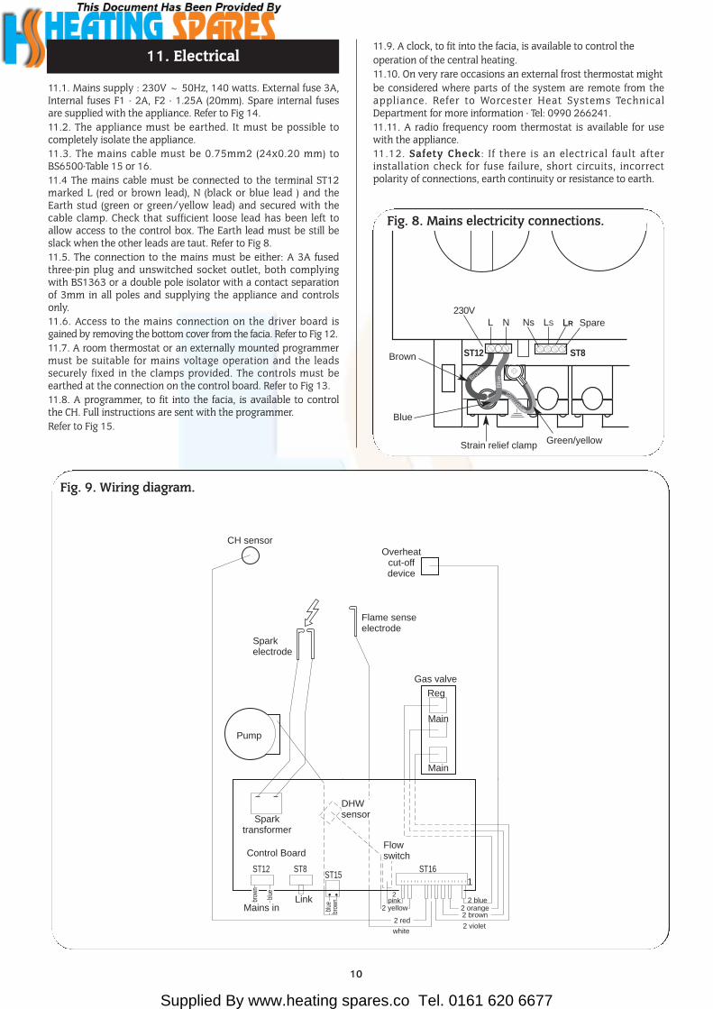
11.1. Mains supply : 230V ~ 50Hz, 140 watts. External fuse 3A,Internal fuses F1 - 2A, F2 - 1.25A (20mm). Spare internal fusesare supplied with the appliance. Refer to Fig 14.11.2. The appliance must be earthed. It must be possible tocompletely isolate the appliance.11.3. The mains cable must be 0.75mm2 (24x0.20 mm) toBS6500-Table 15 or 16. 11.4 The mains cable must be connected to the terminal ST12marked L (red or brown lead), N (black or blue lead ) and theEarth stud (green or green/yellow lead) and secured with thecable clamp. Check that sufficient loose lead has been left toallow access to the control box. The Earth lead must be still beslack when the other leads are taut. Refer to Fig 8.11.5. The connection to the mains must be either: A 3A fusedthree-pin plug and unswitched socket outlet, both complyingwith BS1363 or a double pole isolator with a contact separationof 3mm in all poles and supplying the appliance and controlsonly.11.6. Access to the mains connection on the driver board isgained by removing the bottom cover from the facia. Refer to Fig 12.11.7. A room thermostat or an externally mounted programmermust be suitable for mains voltage operation and the leadssecurely fixed in the clamps provided. The controls must beearthed at the connection on the control board. Refer to Fig 13. 11.8. A programmer, to fit into the facia, is available to controlthe CH. Full instructions are sent with the programmer. Refer to Fig 15.
11.9. A clock, to fit into the facia, is available to control the operation of the central heating.11.10. On very rare occasions an external frost thermostat might be considered where parts of the system are remote from theappliance. Refer to Worcester Heat Systems TechnicalDepartment for more information - Tel: 0990 266241.11.11. A radio frequency room thermostat is available for usewith the appliance.11.12. Safety Check : If there is an electrical fault afterinstallation check for fuse failure, short circuits, incorrectpolarity of connections, earth continuity or resistance to earth.
10
11. Electrical
Strain relief clamp Green/yellow
Brown
Brown
Blu
e
Green/yellow
Blue
L230V
ST12
N Ns LRLS
Fig. 8. Mains electricity connections.
LR Spare
ST8
Overheatcut-offdevice
Flame senseelectrode
Sparkelectrode
Sparktransformer
Mains inLink
Control Board
DHWsensor
Flowswitch
ST16
2 blue2 orange2 brown
Fig. 9. Wiring diagram.
brow
nbl
ue
blue
brow
n
2 violetwhite
2 red
2 yellow
2pink
ST12 ST8ST15
Pump
CH sensor
Gas valve
Reg
Main
1
Main

Supplied By www.heating spares.co Tel. 0161 620 6677
11
Mai
nsin
dica
tor
On/
Off
switc
h
ST
8(L
S)
ST
8(L
R)
ST
8(N
S)
ST
15P
in L
RE
L1
Pump
ST
12 P
in N
Opt
iona
l lin
k
Roo
mth
erm
osta
t
Tran
sfor
mer
Fus
e F
2(1
.25A
Slo
w)
Fus
e F
1(2
A S
low
)
N
ST
12 P
in L
LIV
EIN
gree
n
Ele
ctro
nics
Electronics
InputsOutputs
Spa
rkIn
dica
tors
Set
tings
Reg
ulat
or v
alve
CH
dem
and
indi
cato
r
Red
Spa
rkel
ectr
odes
DH
Wde
man
din
dica
tor
Red
Fla
me
dete
ctin
dica
tor
Red
Mai
n va
lve
Mai
n va
lve
Flo
w s
witc
h
CH
sen
sor
DH
W s
enso
r
Fla
me
sens
e
Ove
rhea
t cut
-off
24V
pro
gram
mer
Reset button
Gas valve mode switch
CH pressure adjust pot
CH Control knob
DHW control knob
Convert AC to lowvoltage electronics
Electronics/microprocessor
(Safety Low Voltage)
Fig. 10. Functional flow diagram.

Supplied By www.heating spares.co Tel. 0161 620 6677
12
Fig 11 - Electrical Connections
13
12
3
4
5
67
8
9
10
11
12
1. ST12-Mains 9. Fuse-F22. Fuse-F1 10. Cable Entry Clamp3. Earth Screw 11. ST13-24volt Controls4. ST8-Room Thermostat 12. Main Harness and Clamp
and External Control 13. Control Panel Pivot-Mains Voltage Point
5. Cable Entry Screw Clamp6. Earth Tag7. ST15-Pump8. ST1-Fan
Fig 12 - Facia Connections Cover
1
2
3
451. Control Panel Fixing Screws2. Facia3. Control Panel Pivot Point4. Connection Cover5. Connection Cover Fixing
Screws
Fig 13 - Mains Voltage External Controls Connections
230
V Ro
om T
herm
osta
t Con
nect
ions
Ns Ls LR Spare
ST8
Ns Ls LR Spare
ST8
Remove Link
Neu
tral
Live
Switc
hed
Live
Neu
tral
Live
Switc
hed
Live
Motor
230
V Pr
ogra
mm
er C
onne
ctio
ns
230
V ro
om th
erm
osta
t and
Prog
ram
mer
Con
nect
ions
Ns Ls LR Spare
ST8
Neu
tral
Live
Switc
hed
Live
Neutral
Live
Switched Live
Motor
Fig 14 - Replacement Fuses1
2
3
4
5
1. Control Panel Pivot 4. Facia PanelPoint 5. Control Board
2. Fuses-F1,F2 Assembly3. Pressure Gauge
Fig 15 - Programmer Connection
65
4
3
1
2
1. Programmer2. Programmer
Fixing Clip3. Pressure
Gauge
4. ProgrammerConnector
5. Facia6. Control
Board

Supplied By www.heating spares.co Tel. 0161 620 6677
NOTE: READ THIS SECTION FULLY BEFORE COMMENCINGINSTALLATION12.1The appliance is supplied suitable for fitting to a sealedsystem. If it is to be fitted to an open vent system refer to section 8.12.2 FLUE OPTIONS.The standard flue length is from 225mm to 420mm measuredfrom the appliance casing to the outer wall.An extension flue kit is available to increase the length to 560mm.The flue must be installed as specified in BS 5440 Part 1.12.3 GENERAL FITTING.Check that the appliance carton contains: Appliance, installer’sinstruction pack, pre-plumbing manifold, wall plate, user’sinformation pack and installer’s hardware pack.Assemble the wall plate to the pre-plumbing manifold as shownin Fig. 16 using the two M4 thread forming screws supplied inthe hardware pack.Check that the position chosen for the appliance is in accordancewith the instructions given in Sections 4 and 5.Hold the wall mounting plate to the wall. Check the manifold ishorizontal. Leave the pre-fitted plastic manifold cover in place to protectthe valves and 'O' rings from dust and dirt during installation.Mark the position of the fixing holes and the position of the fluehole onto the wall.Drill the eight retaining holes 70mm (2.75in.) deep. Fit the wallplugs supplied with the appliance.Cut the 365mm (14.4in.) x 265mm (10.5in.) hole through the wallfor the balanced flue air duct. Make good any plaster or brickwork.Screw the wall mounting plate into position using the screwssupplied with the appliance. See Fig. 16.Connect the gas, water and pressure relief valve connections tothe manifold. The primary system should be flushed and treatedin accordance with the recommendations of BS 7593:1992.Remove the cabinet front cover by lifting and pulling forward.Remove the inner casing by unscrewing the four retaining screws.Remove the flue hood by releasing the clip at the front andpulling forwards.12.3 AIR AND FLUE DUCT PREPARATION AND ASSEMBLYFrom the carton containing the flue kit, remove the flue terminal,flue duct and the package containing: 4 No. 8 wall plugs, 1 rollducting tape, 4 No. 8 wood screws, 1 tube of silicone sealant.
Separate the air and flue ducts from the terminal.Measure the distance from the inside edge of the mounting plateto the outside of the wall W. See Fig. 19.Fit the air ducts together and adjust the total length until itcorresponds with the W dimension. Using the ducting tapeprovided firmly tape the joint. See Fig. 18.From the inside, push the assembled air ducts through theaperture with the flanged end of the duct on the inside.Apply the silicone sealant in a bead approximately 10mmdiameter around the balanced flue locating spigot on the backface of the appliance. See Fig. 20.Remove the plastic cover from the manifold and make sure thatthe 'O' rings are fitted clean and lubricated.Lift the appliance onto the mounting plate and locate the two M6studs on the mounting plate into the two holes in the back of thecase. Locate the balanced flue spigot into the balanced flue airducts. Fasten the appliance with the two M6 nuts and also usethe caps (from Installer Hardware Pack) to secure the appliance tothe pre-plumbing manifold at the bottom. (See Fig. 16). Access tothese pegs and caps can be made easier by removing the bottompanel. Refer to Section 15.3, d.
12. Installation
13
Fig. 17. Fixing the appliance to the wall mounting plate.
Wall mounting plate
Appliance Keep appliancevertical
Step 1. Rest appliance onwall mounting plate and pushback, engaging valves first.
Step 2. Secure at topwith the M6 nuts andwashers supplied (2).
Step 3. Secureat bottom withcaps and boltssupplied (3).
Fig. 16. Fixing the wall mounting plate.
410crs
4257
16
20
42
10
310c
rs
844
99
365mm
Wall aperture
Interior wallsurface
Wall mountingplate
Exteriorwallsurface
265
wal
lap
ertu
re

Supplied By www.heating spares.co Tel. 0161 620 6677
From the outside, make good the gap between the air duct andthe brickwork. Fit the flue terminal to the air duct and mark theposition of the four fixing holes. Drill four holes 5mm (0.19in.)diameter x 30mm (1.25in.) deep in the wall and fit the wall plugsprovided.Fix the flue terminal to the wall using the four No. 8 woodscrews.NOTE: The flue terminal is not symmetrical and the narrow airinlet gap is at the top. The top flange is marked TOP.From inside the appliance enter the exhaust duct, plain end first.Engage the exhaust duct over the front half of the exhaust ductattached to the flue terminal. Slide in the exhaust duct andsecure the flange with the screws but do not tighten.Engage the spigot on the flue hood into the exhaust duct andslide into position on the heat exchanger. Fix into position withthe clip at the front.Tighten the two screws securing the exhaust duct.
12.5 FINAL INSTALLATIONCheck that all the water and gas connections have beentightened. Unscrew the automatic air vent cap. Refer to Fig. 28.
If a facia mounted programmer is to be fitted follow instructionswith the programmer..Hinge down the facia as described in Section 15.3, c.Connect the mains electrical supply to the appliance at terminalST 12 See Fig. 8. Connect any room and/or frost thermostats.The electrical leads must pass through the appropriate space inthe control panel and be fixed with the cable clamps provided.See Figs. 11 and 12. Refit the facia panel.Test the gas supply pipework up to the appliance for soundnessas indicated in BS 6891.Refer to Section 13.2 for a full description of the filling, ventingand the pressurising of the system.If the appliance is not to be commissioned immediately, replacethe cabinet front panel. Check that the gas supply, the electricalsupply and the water connections are all turned off.If the premises are to be left unoccupied during frosty conditions,then drain the appliance and system. For short inoperativeperiods, leave the appliance under the control of the built in frostthermostat or the remote frost thermostat (if fitted) or leaveoperating continuously with the room thermostat set at 6°C.
14
Fig. 18. Air duct adjustment.
Fig. 19. Arrangement of balanced flue and terminal.
Seal telescopicjoint with tapeprovided
345 mm
245 mm
10 mm diametercontinuous seam ofsilicone sealant allaround. (See Fig. 18).
Drill and plugwall.Secureterminal towall with fourscrews.
Drill and plug wall.Secure mounting plate witheight screws.
Telescopic flue duct
Telescopic air duct
Tape joint
(W)WALL THICKNESS225 mm minimum560 mm maximum
W
Fig. 20. Silicone bead.
10 mm (0.4in.)diameter continuousseam of siliconesealant all around.
Supplied By www.heating spares.co Tel. 0161 620 6677
13.1 SUMMARYThe appliance is dispatched with the controls set to provide amaximum output for domestic hot water and central heating of24 kW (81,900 Btu/h).The appliance automatically modulates to satisfy lower heat loads.Domestic Hot Water CircuitConfirm that the mains water supply has been flushed out atinstallation. If not it will be necessary to disconnect the coldwater inlet pipe from the appliance and thoroughly flush.Central Heating SystemConfirm that the system has been fully flushed out at installationusing a flushing agent. Flush the system before starting tocommission the appliance and, at the end of the commissioningprocedure, add a suitable flushing agent and drain whilst hot.Immediately refill and re-pressurise.Gas Service. The complete system, including the meter, must beinspected and tested for soundness and purged as indicated inBS 6891. In the event of a leak, or suspected leak, at the ‘O’ ringjoint on the main appliance manifold, connect a manometer tothe test point on the inlet of the multifunctional gas valve. Asoundness test carried out after turning off the appliance gascock will test the section between the gas cock and the gasvalve, thus enabling the leak to be traced to either a visible jointor to the ‘O’ ring.13.2 APPLIANCE AND CENTRAL HEATING
SYSTEM – PREPARATIONRemove the cabinet front panel.Check that the electrical supply and the gas service to theappliance are off.Check that all the water connections throughout the system are tight.Open the system valves at the appliance. Open all the radiatorvalves, fill the system and vent each radiator in turn.Remove the bottom panel to gain access to the filling loopassembly. (The grey knob for the filling loop is packed in thehardware pack and should be fitted as shown in Fig. 6,6a.Insert the bayonet end of the filling key into the correspondingcutouts in the filling loop housing and twist to lock the key in place.Turn the grey knob anti-clockwise to allow water ingress and filluntil the pressure gauge reads 2.5 bar.Turn the grey knob clockwise to stop filling and remove the fillingkey by lining up the bayonet end of the key with the cutouts inthe filling loop housing and withdrawing the key.N.B. The key must always be removed from the filling loophousing after the system has been filled to prevent accidentalfilling and to comply with Byelaw 14 of the Water ByelawsScheme.Store the key in a safe place for future use and refit the bottompanel. The automatic air vent will vent the appliance. Check that the airvent cap has been loosened. Refer to Fig. 28.Check that the pressure relief valve operates by turning the knobanti-clockwise until it releases. Water should be expelled fromthe discharge pipe. Refer to Fig. 22. Lower the facia panel to gain access. Refer to Section 15.3, c.Set the Expansion Vessel PressureThe charge pressure of the expansion vessel as dispatched is 0.5bar, which is equivalent to a static head of 5 metres (17 ft). Thecharge pressure must not be less than the static head at thepoint of connection. Refer to Fig.18. A Schraeder type tyre valveis fitted to the expansion vessel to allow the charge pressure tobe increased if necessary.Set the System PressureRelease water from the system using the relief valve test knobsee Fig. 22, until the system design pressure is obtained, up to amaximum of 1.5 bar.Initial system design pressure (bar) = Expansion vessel chargepressure + 0.3 bar.NOTE: 1 bar is equivalent to 10.2 metres (33.5ft) of water.Set the movable pointer on the pressure gauge to coincide with
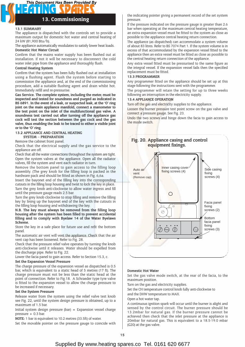
the indicating pointer giving a permanent record of the set systempressure.If the pressure indicated on the pressure gauge is greater than 2.6bar when operating at the maximum central heating temperature,an extra expansion vessel must be fitted to the system as close aspossible to the appliance central heating return connection.The appliance (as dispatched) can accommodate a system volumeof about 83 litres. Refer to BS 7074 Part 1. If the system volume is inexcess of that accommodated by the expansion vessel fitted to theappliance then an extra vessel must be fitted as close as possible tothe central heating return connection of the appliance.Any extra vessel fitted must be pressurised to the same figure asthe integral vessel. If the expansion vessel fails then the specifiedreplacement must be fitted. 13.3 PROGRAMMERAny programmer fitted on the appliance should be set up at thisstage following the instructions sent with the programmer.The programmer will retain the setting for up to three weeksfollowing an interruption in the electricity supply.13.4 APPLIANCE OPERATIONTurn off the gas and electricity supplies to the appliance.Loosen the burner pressure test point screw on the gas valve andconnect a pressure gauge. See Fig. 23.Undo the two screws and hinge down the facia to gain access tothe mode switch.
Domestic Hot WaterSet the gas valve mode switch, at the rear of the facia, to themaximum position. Turn on the gas and electricity supplies.Set the CH temperature control knob fully anti-clockwise to and the DHW temperature to MAX.Open a hot water tap.A continuous ignition spark will occur until the burner is alight andsensed by the control circuit. The burner pressure should be13.2mbar for natural gas. If the burner pressure cannot beachieved then check that the inlet pressure at the appliance is20mbar for natural gas. This is equivalent to a 18.5-19.0 mbar(G20) at the gas valve.
13. Commissioning
15
Auto airvent(Remove cap)
Fig. 20. Appliance casing and controlequipment fixings.
Inner casing coverfixing screws (4)
Side casingfixingscrews (4)
Facia panelfixingscrews (2)
Bottomfacia panelfixingscrews (3)

Supplied By www.heating spares.co Tel. 0161 620 6677
Set the gas valve mode switch to the minimum position.The burner pressure will drop to the minimum setting whichshould be 2mbar for natural gas. Test for gas soundness at the joint between the burner and the gasvalve with leak detection fluid.NOTE: The burner pressure is factory set and if (after checking thatthe supply pressure is sufficient) the correct pressure is notobtained then Worcester Heat Systems Service Department shouldbe contacted.If the appliance does not light, check that it is not in the ‘lockout’state by pressing the lockout reset button. See Fig. 25.Set the gas valve mode switch back to the normal position andrefit the facia.Turn off the electricity supply, and then back on again to reset thecontrols.Gradually close the hot tap and check that the burner pressuredrops. Fully open the tap and check that the burner pressure rises.Fully close the tap and check that the burner goes off. The fanmay continue running until the appliance has cooled to a presettemperature.Set the Operating Switch to OFF.
Central HeatingCheck that all the radiator valves are open. Set the roomthermostat and the Central Heating Temperature Control tomaximum. Set the DHW temperature control to MIN.On sealed systems check that the system is pressurised and set tothe required pressure as indicated on the gauge.Set the Programmer, if fitted, to HEATING & WATER.Set the operating switch to ON.The burner will light.The appliance will modulate its output from 11.9 to 24.0 kW overa period of about two minutes.Check the system to ensure that all the radiators are heating upevenly. If not then bleed each radiator through its vent screw.Shut down all but one of the radiators and observe the burnerpressure fall. Open all of the radiator valves and check that theburner pressure rises.Balance the system so that the required temperature differenceacross the central heating flow and return pipes is obtained. SeeTable 3.
16
Fig. 22. Pressure relief valve.
Turn knobanti-clockwiseto test
Pressurereliefvalve
Fig. 24. Central heating by-pass adjustment.
Fig. 23. Gas Valve Max2mm
Allen key
Min3mm
Allen key
Gas valve sealing cap
Burner pressuretest point
Electrical connectionsmodulator (Blue:Blue)
Minimum / Maximum pressureadjuster - rotate Allen key clockwise toincrease and anti-clockwise todecrease the pressure.
Inlet pressuretest point
Main gasvalve connections
Gas valve bracket
Supplied By www.heating spares.co Tel. 0161 620 6677
Adjust the central heating by-pass valve until the sametemperature difference is obtained. See Fig. 24. This should becarried out with only a single radiator operating. If thermostaticradiator valves are fitted then one radiator should be leftuncontrolled. The bypass valve should never be fully closed.Set the room thermostat to minimum and check that the burnergoes out. Reset the room thermostat to maximum and the burnerwill re-light and follow the normal operating procedure.Check for proper ignition of the burner after a break in the gassupply. Turn off the gas service cock and wait for 60 seconds. Theburner will go out but sparking from the electrode will continuefor 10 seconds when the appliance will enter a ‘lockout’ state.Carefully open the gas service cock, press the lockout reset buttonand observe the burner re-light and follow the normal sequence ofoperation. Refer to Fig.25.Set the Operating Switch to OFF.Turn off the gas service cock and the electrical supply to theappliance.Drain the system while the appliance is still hot.Refill, vent and, with a sealed system, re-pressurise as described inSection 13.2.Domestic Hot Water and Central HeatingTurn on the electricity supply to the appliance and open the gassupply cock at the appliance.Set the Operating Switch to ON. If a programmer is fitted, set thedomestic hot water to Continuous or 24Hrs and the central heatingto ON. The burner will light and heat will pass into the system. Setthe DHW temperature to MAX and turn on a hot water tap andcheck that fully heated hot water is discharged from the tap.Close the tap and the burner will go off. The appliance will thenreturn to the central heating mode and automatically balancewith the system requirements.Set the Operating Switch to OFF and the burner will go out.
13.5 COMPLETION OF COMMISSIONINGDisconnect the pressure gauge from the gas valve and tighten thetest point screw.Restart the appliance and check for gas soundness around thetest point screw.Refit the cabinet front panel.If the appliance is being passed over to the user immediately, referto Section 14 - Instructions to the User. If the appliance is to be left inoperative, check that the OperatingSwitch is set to OFF. Turn off the gas service cock. For short inoperative periods, leave the appliance under thecontrol of the built in frost thermostat or the remote frostthermostat (if fitted) or leave operating continuously with the room thermostat set at 6°CDo not switch off the electricity supply.If there is any possibility of the appliance and the system beingleft totally unused in freezing conditions then switch off the gasand electricity and drain the appliance and the system.
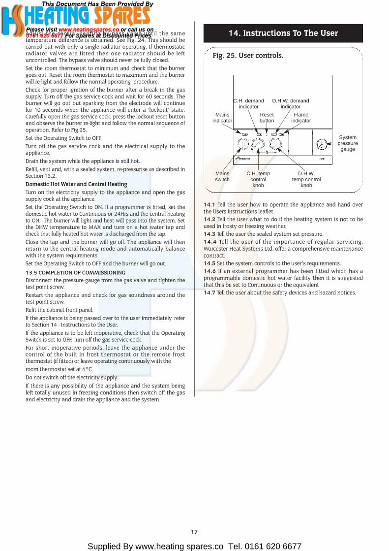
14.1 Tell the user how to operate the appliance and hand overthe Users Instructions leaflet.14.2 Tell the user what to do if the heating system is not to beused in frosty or freezing weather.14.3 Tell the user the sealed system set pressure.14.4 Tell the user of the importance of regular servicing.Worcester Heat Systems Ltd. offer a comprehensive maintenancecontract.14.5 Set the system controls to the user’s requirements.14.6 If an external programmer has been fitted which has aprogrammable domestic hot water facility then it is suggestedthat this be set to Continuous or the equivalent14.7 Tell the user about the safety devices and hazard notices.
14. Instructions To The User
17
Fig. 25. User controls.
C.H. demandindicator
D.H.W. demandindicator
Mainsindicator
Mainsswitch
C.H. tempcontrolknob
D.H.W.temp control
knob
Systempressuregauge
Resetbutton
Flameindicator

Supplied By www.heating spares.co Tel. 0161 620 6677
15.1 SERVICINGTo ensure continued efficient operation of the appliance itmust be checked and serviced as necessary at regularintervals. The frequency of servicing will depend upon theparticular installation conditions and usage, but once peryear should generally be adequate. The extent of the servicerequired by the appliance is determined by the operatingcondition of the appliance when tested by fully qualifiedengineers.Any service work must be carried out by competentengineers such as British Gas or Corgi registered personnel.15. 2 PRE-SERVICE INSPECTIONCheck that the flue terminal and the terminal guard, (if fitted), are clear.If the appliance is in a compartment, check that the ventilationopenings in the compartment door or walls are clear. See Section6 - Air Supply.Check the system and remake any joints or fittings which showsigns of leakage. Refill, vent and re-pressurise as described inSection 13.2.Operate the appliance and the system taking note of any faults.Measurement of the Flue GasesFor consistency of results of the flue gas measurements it isnecessary to have a constant output and stationary equilibrium.
Switch on the appliance.Switch to DHW and CH mode.Hinge down the facia.Turn the Mode Switch to the “Max.” position.Wait until the appliance reaches stationary equilibrium(approx. 10 minutes).Insert the probe into the flue duct.
Expected measurements should be between:CO: 0.0015 and 0.0025%.CO2: 4.5 - 5.5%.
After taking the measurement:Turn the Mode Switch back to the “normal” position.Put the facia back in to its normal position.
SAFETYDisconnect the electrical supply at the mains and turn off thegas supply at the gas service cock on the appliance beforeservicing.After completing the service always test for gas soundness asindicated in BS 6891.15. 3 COMPONENT ACCESSTo carry out a full and comprehensive service of the applianceremove the following parts to gain access to the componentswhich need to be checked or serviced.(a) Cabinet Front Panel. Remove by lifting off the supports.(b) Inner Casing Cover. Check that the electricity supply to theappliance is turned off. Remove the cabinet front panel. Unscrew thefour screws securing the cover to the casing and lift off. See Fig. 21.(c) Facia Panel. Check that the electricity supply to the applianceis turned off. Remove the cabinet front panel. Unscrew the twoupper screws as shown in Fig. 21 and hinge down the faciataking care not to distort the pressure gauge capillary tube orelectrical connections.(d) Bottom panel. Hinge down the facia panel. Disengage thefront edge of the bottom panel from the two clips and removethe bottom panel from the appliance.(e) Flue Hood Assembly. Undo the two screws securing the fluehood. Lift and slide the flue hood assembly from the appliance.See Fig. 26. When refitting the hood ensure that the rear returnedge passes under the lip at the rear of the combustion chamber.(f) Combustion Chamber Front and Sides. Remove the innercasing cover. Slacken off to the end of the thread but do not
remove the two wing nuts securing the combustion chamber.Unhook the securing rods out of the locating holes in thecombustion chamber sides. Ease the combustion chamber frontand side assembly clear of the appliance. Refer to Fig. 26. (g) Burner Assembly. Remove the combustion chamber frontand sides. Pull off the two spark electrode leads and disconnectthe flame sense lead at the plastic connector under the innercasing. NOTE: The flame sensing lead is attached to the burner.When the burner is removed ensure this lead is fed through theinner casing. Remove the grommet seal to allow the plasticconnection to pass through the inner casing. Unscrew the G 3/4
union nut on top of the gas valve and retain the sealing washer.Unscrew the front burner fixing screw. Lift the burner and easethe union nut through the inner casing sealing grommet.Remove the burner assembly clear of the inner casing. Ensure the flame sensing lead passes through the base of theinner casing. See Fig. 27.15. 4 SERVICE OF COMPONENTSClean the Main Burner. Brush the blade tops and mixing tubewith a soft brush and check that all the flame ports are clear.Remove any blockages with a non-metallic brush. Inspect theinjector and clean with a soft brush. Replace the injector if itappears damaged. Do not use a wire brush or anything likely tocause damage. Replace the spark and sense electrodes if theyappear damaged. Clean the Gas to Water Heat Exchanger. Cover the burnermanifold hole in the combustion chamber bottom panel with acloth. Clean the heat exchanger using a soft brush. Remove thedeposits from the bottom of the combustion chamber. Do notdistort any of the blades.Combustion Chamber Insulation. Examine and replace anypads that are damaged. Remove any dust or deposits using asoft brush after first dampening the pads.Reassemble the appliance in the reverse order.Check that all components are in place and correctly fixed. Leavethe cabinet front panel to be fitted after checking the operationof the appliance.15. 5 TEST THE APPLIANCEOn completion of the service and reassembly of the appliance,check for gas soundness and the correct operation of theappliance as described in Section 13-Commissioning.Refit the cabinate front panel and reset the controls to the usersrequirements.
15. Inspection And Servicing
18
Fig. 26. Appliance components and fixings(upper assembly).
Flue hoodfixingscrews
Centralheatingsensor
Overheatthermostat
Flue hood
Combustionchamberfixing bolts(2)
Burner fixing screw
Combustionchamberfront andsides
Supplied By www.heating spares.co Tel. 0161 620 6677
16.1 SAFETYSwitch off the electricity and gas supplies before replacing anycomponents. After the replacement of any components, checkfor gas soundness where relevant and carry out functionalchecks as described in Section 13 - Commissioning
16.2 COMPONENT ACCESSTo replace components it is necessary to remove one or moresections of the cabinet and cover plates within the appliance asdescribed in Section 15.3. Any 'O' ring or gasket that appearsdamaged must be replaced. Complete gasket and 'O' ring packsare available for the gas and water connections on the appliance.The facia panel may also need to be hinged down as described inSection 15.3, c.16.3 DRAINING THE APPLIANCECheck that the electricity supply to the appliance is turned off.Before removing any component holding water it is importantthat as much water as possible is removed from the appliance.(a) Central Heating Circuit. Turn off the central heating flow andreturn valves at the appliance. Fit tubes to the drain taps on theflow and return manifolds and open the drain taps about oneturn, make sure that the dust cap on the auto air vent isloosened. See Fig. 18. Close the drain taps when the flow hasstopped. Be careful not to overtighten the drain taps. Somewater will remain in the expansion vessel, pump, diverter valve,water to water and Gas to Water heat exchangers and extra caremust be taken when removing these components.(b) Domestic Hot Water Circuit. Turn off the mains cold supplyvalve at the appliance and open the lowest hot water tap. Aquantity of water will remain in the Water to Water heatexchanger and the diverter valve and extra care must be takenwhen removing these components.Replace any components removed from the appliance in the
reverse order using new gaskets/'O' rings/sealant wherenecessary. Always check that any electrical connections arecorrectly made and that all screws are tight.
16.4 COMPONENT REPLACEMENT1. Automatic Air Vent.Remove the inner casing cover as described in Section 15.3 (b).Drain the central heating circuit as described in Section 16.3 (a).Remove the circlip and lift the assembly from the appliance.Unscrew air vent from the pipe. Check the condition of the fibrewasher.Fit the replacement assembly, making sure the ‘O’ ring is in goodcondition.Ensure that the circlip is correctly fitted and the dust cap isloosened.Open the valves and fill and re-pressurise the system asdescribed in Section 13.2.2. Overheat Thermostat. .Check that the electricity supply to the appliance is turned off.Remove the inner casing cover as described in Section 15.3 (b).Carefully pull off the two wires from the thermostat head.Undo the two M3 screws and remove from the appliance.Fit the replacement thermostat in the reverse order ensuring thatsome heat sink compound is between the thermostat and theplate.
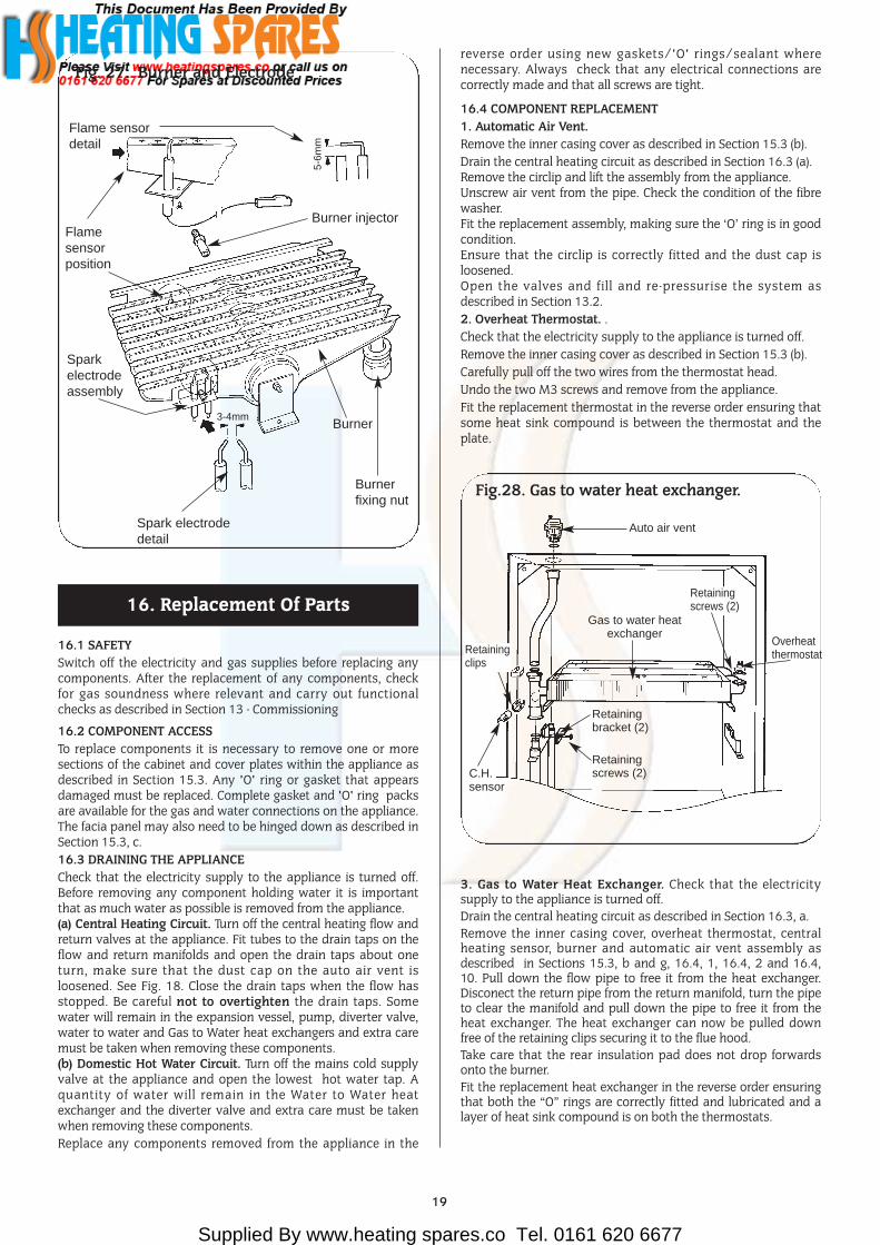
3. Gas to Water Heat Exchanger. Check that the electricitysupply to the appliance is turned off.Drain the central heating circuit as described in Section 16.3, a.Remove the inner casing cover, overheat thermostat, centralheating sensor, burner and automatic air vent assembly asdescribed in Sections 15.3, b and g, 16.4, 1, 16.4, 2 and 16.4,10. Pull down the flow pipe to free it from the heat exchanger.Disconect the return pipe from the return manifold, turn the pipeto clear the manifold and pull down the pipe to free it from theheat exchanger. The heat exchanger can now be pulled downfree of the retaining clips securing it to the flue hood. Take care that the rear insulation pad does not drop forwardsonto the burner.Fit the replacement heat exchanger in the reverse order ensuringthat both the “O” rings are correctly fitted and lubricated and alayer of heat sink compound is on both the thermostats.
16. Replacement Of Parts
Fig.28. Gas to water heat exchanger.
Auto air vent
Gas to water heatexchanger
Retainingbracket (2)
Retainingscrews (2)
Overheatthermostat
Retainingscrews (2)
C.H.sensor
19
Fig. 27. Burner and Electrode
3-4mm
5-6m
m
5-6m
m
Spark electrodeassembly
Spark electrodedetail
Flamesensorposition
Flame sensordetail
Burner injector
Burner
Burner fixing nut
Retainingclips

Supplied By www.heating spares.co Tel. 0161 620 6677
Open the valves and fill and re-pressurise the system asdescribed in Section 13.2.
4. Combustion Chamber Insulation. Refer to Fig. 29.Check that the electricity supply to the appliance is turned off.Drain the central heating circuit as described in Section 16.3, a.Remove the inner casing cover, combustion chamber, fluehood assembly, burner, and Gas to Water heat exchanger asdescribed in Sections 15.3 ,b, e and g, and 16.4 ,3. Remove thefibre insulation pads from the combustion chamber side, rear,and front sections. To avoid the risk of fine particles dampenthe pads before removal.Fit the replacement pads in the reverse order taking care not todamage them.Open the valves and fill and re-pressurise the system asdescribed in Section 13.2.
5. Burner. Refer to Fig. 27.Check that the electricity and gas supplies to the appliance areturned off.Remove the burner assembly as described in Section 15.3, g.Fit the replacement burner in the reverse order taking care not todamage the electrode leads.6. Burner Injector. Refer to Fig. 27.Remove the burner as described in Section 15.3, g.Unscrew the brass injector from the burner.Fit the replacement injector in the reverse order.7. Spark Electrode Assembly. Refer to Fig. 27.Remove the combustion chamber front and sides as described in15.3, f.Carefully pull off the two electrode leads,Undo the M4 extended nut and remove the spark electrodeassembly from the burner.Fit the replacement electrode in the reverse order, checking thatthe spark gap is 3 to 4mm.8. Flame Sensor. Refer to Fig. 27.Remove the burner as described in Sections 15.3, g and 16.4, 5.Undo the M3 screw and remove the sense electrode from theburner.Fit the replacement electrode in the reverse order, checking thatthe sense gap is 5 to 6mm.9. Gas Valve. Refer to Fig. 23.Check that the electricity and gas supplies to the appliance areturned off.
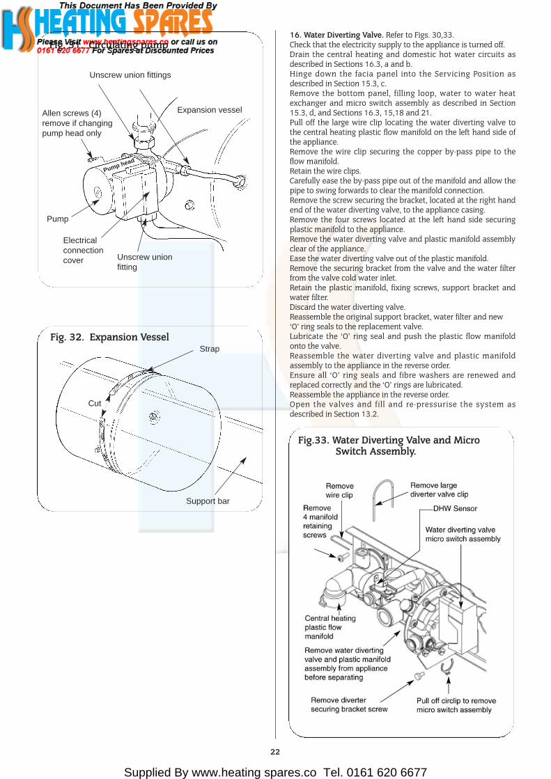
Hinge down the facia panel into the servicing position asdescribed in Section 15.3, c.Remove the air pressure switch bracket as described inSection 16. 3, 2.Undo the two G3⁄4 inch nuts on the gas valve and the two M4screws on the gas valve bracket and withdraw the valve. Whilst supporting the valve carefully pull off the three electricalsolenoid plug connections.Fit the replacement gas valve in the reverse order ensuring thesealing washers are correctly fitted.Turn on the gas supply and check for soundness.To set the burner pressure. Refer to Fig. 23.The minimum and maximum burner pressure must be set after anew gas valve has been fitted.Follow the procedure described in Section 13.4 - ApplianceOperation.The minimum burner pressure must be set first, sincemaximum is adjusted simultaneously.Start the appliance in the domestic hot water mode as describedin Section 13.4. - Appliance Operation.Turn the gas mode switch on the rear of the facia to minimum.Adjust the minimum pressure screw on the gas valve to give aburner pressure of 2.0mbar for natural gas.Turn the gas mode switch on the rear of the facia to maximum.Adjust the maximum pressure screw on the gas valve to give aburner pressure of 13.2mbar for natural gas. Turn the gas mode switch on the rear of the facia to normal.After completing the adjustments, check the minimum andmaximum pressures and adjust as necessary.Ensure the appliance lights in the central heating modeIt should not be necessary to alter the central heatingpotentiometer setting when the gas valve only is replaced andthe minimum and maximum pressures are set.10. Central Heating Sensor. Refer to Fig 28.Remove the inner casing cover as described in Section 15.3, b.Check that the electricity supply to the appliance is turned off.Carefully pull off the two leads from the sensor.Pull off the sensor and spring retaining clip from the pipe.Fit the replacement sensor in reverse order with a layer of heatsink compound between the faces. Refit the leads.11. Domestic Hot Water Sensor. Refer to Fig. 30,33.Check that the electricity supply to the appliance is turned off.Hinge the facia panel into the servicing position as described inSection 15.3, c.Carefully pull off the two leads from the sensor.Undo and remove the screw, pull off the sensor and springretaining clip from the pipe.Fit the replacement sensor in the reverse order ensuring a layerof heat sink compound is between the faces. Refit the leads.12. Circulating Pump. Refer to Figs. 30,31. Check that the electricity supply to the appliance is turned off.Drain the central heating circuit as described in Section 16.3, a.Hinge the facia panel into the servicing position as described inSection 15.3, c.Undo the two union nuts and the pipe to the expansion vessel,remove the pump from the pipe-work. Support the pump andremove the electrical cover.Disconnect the electrical wires taking note of their positions.Fit the replacement pump in the reverse order using new sealingwashers.Alternatively replace the pump head only by removing the fourAllen screws on the pump, remove the head and support whilstremoving the electrical connections. Refit the new head.Open the valves and fill and re-pressurise the system asdescribed in Section 13.2.NOTE: The direction of flow should be downwards. The speedshould always be set to maximum.
Fig. 29. Combustion Chamber Insulation
Combustion chamber front andside assembly
Side insula-tionpad
Side insula-tionpad
Front insulation pad
When reassembling ensure theselocations are correctly fitted in theslots at the rear of the inner casing
View from inside the combustion chamber
20

Supplied By www.heating spares.co Tel. 0161 620 6677
13. Expansion Vessel. Refer to Figs. 30,32.Drain the central heating circuit as described in Section 16.3, a.Hinge the facia panel into the servicing position as described inSection 15.3, c.Remove the gas to water heat exchanger, water to water heatexchanger and pump as described in 16.4, 3,12 and 18 andremove the vessel.Fit the replacement vessel in the reverse order.Open the valves and fill and re-pressurise the system asdescribed in Section 13.214. Pressure Relief Valve. Refer to Fig. 22.Drain the central heating circuit as described in Section 16.3, a.Hinge down the facia panel as described in Section 15.3, c.Remove the bottom panel as described in Section 15.3, d.Pull out the retaining clip and remove the pressure gauge connection. Undo the discharge pipe connection and remove the
valve taking care not to distort the pipework.Fit the replacement valve in reverse order. Reconnect thedischarge pipe.Open the valves and fill and re-pressurise the system asdescribed in Section 13.2.15. Water Diverting Valve Micro Switch Assembly. Refer to Figs. 30,33.Check that the electricity supply to the appliance is turned off.Hinge down the facia panel as described in Section 15.3(c).Remove the bottom panel as described in Section 15.3(d)Using a pair of fine nosed pliers, pull the circlip off and removethe micro switch assembly from the valve. Remove the blackcover and carefully pull off the connections from the terminalson the micro switches. Withdraw the switch assembly from the appliance.Fit the replacement micro switch assembly in the reverse order.
21
Fig. 28. Appliance Components (lower assembly)
Domestic hot water sen-sor (not shown) locatedbehind water to water heatexchanger
Circulating pump
Flow pipe from pump andunion connection
Expansion vessel
Gas valve
Water to water heat exchanger
Pressure relief valve
Drain tap(C.H. Return)
Pressure GaugeFacia and controls shownin the service position
Plastic water cover
Filling loop
Water diverting valveand micro switch assembly
Drain tap C.H. flow
Supplied By www.heating spares.co Tel. 0161 620 6677
16. Water Diverting Valve. Refer to Figs. 30,33.Check that the electricity supply to the appliance is turned off.Drain the central heating and domestic hot water circuits asdescribed in Sections 16.3, a and b.Hinge down the facia panel into the Servicing Position asdescribed in Section 15.3, c.Remove the bottom panel, filling loop, water to water heatexchanger and micro switch assembly as described in Section15.3, d, and Sections 16.3, 15,18 and 21.Pull off the large wire clip locating the water diverting valve tothe central heating plastic flow manifold on the left hand side ofthe appliance.Remove the wire clip securing the copper by-pass pipe to theflow manifold.Retain the wire clips.Carefully ease the by-pass pipe out of the manifold and allow thepipe to swing forwards to clear the manifold connection.Remove the screw securing the bracket, located at the right handend of the water diverting valve, to the appliance casing.Remove the four screws located at the left hand side securingplastic manifold to the appliance.Remove the water diverting valve and plastic manifold assemblyclear of the appliance.Ease the water diverting valve out of the plastic manifold.Remove the securing bracket from the valve and the water filterfrom the valve cold water inlet.Retain the plastic manifold, fixing screws, support bracket andwater filter.Discard the water diverting valve.Reassemble the original support bracket, water filter and new ‘O’ ring seals to the replacement valve.Lubricate the ‘O’ ring seal and push the plastic flow manifoldonto the valve.Reassemble the water diverting valve and plastic manifoldassembly to the appliance in the reverse order.Ensure all ‘O’ ring seals and fibre washers are renewed andreplaced correctly and the ‘O’ rings are lubricated.Reassemble the appliance in the reverse order.Open the valves and fill and re-pressurise the system asdescribed in Section 13.2.
22
Fig. 31. Circulating pump
Expansion vessel
Unscrew union fittings
Allen screws (4)remove if changingpump head only
Pump head
Pump
Electricalconnectioncover Unscrew union
fitting
Fig. 32. Expansion VesselStrap
Cut
Support bar
Fig.33. Water Diverting Valve and Micro Switch Assembly.

Supplied By www.heating spares.co Tel. 0161 620 6677
17. Inlet Water Filter. Refer to Fig. 34.Check that the electric supply to the appliance is turned off.Drain the central heating and domestic circuits as described inSections 16.2, a and b.Hinge down the facia panel into the servicing position as described in Section 15.3, c.Follow the procedures as described in Section 15.3,16 andremove the water diverting valve from the appliance.Remove the water filter from the cold water inlet.Discard or clean the filter.Fit the replacement filter (push fit) in the reverse order.Reassemble the appliance in the reverse order. Open the valves and fill and re-pressurise the system asdescribed in Section 13.2.18. Water to Water Heat Exchanger. Refer to Fig. 34.Check that the electricity supply to the appliance is turned off.Drain the central heating and domestic hot water circuits asdescribed in Sections 16.3, a and b.Hinge down the facia panel into the servicing position asdescribed in Section 15.3, c.Remove the bottom panel as described in Section 15.3, d.Remove the filling loop as described in Section 16.4, 21. Undothe diverter valve connection. Remove the bolt and circlip andpull the heat exchanger forward and away from the appliance.Fit the replacement heat exchanger in the reverse order.Open the valves and fill and re-pressurise the system asdescribed in Section 12.2.19. Domestic Hot Water Flow Restrictor.Remove the water to water heat exchanger assembly asdescribed in Section 15.4.18.The plastic flow restrictor is located within the brass housing on
the heat exchanger. Refer to Fig. 34.Fit the replacement flow restrictor and reassemble in the reverseorder ensuring the fibre washers and ‘O’ rings are in place.20. Pressure Gauge. Refer to Figs. 30,34.Check that the electricity supply to the appliance is turned off.Drain the central heating circuit as described in Section 16.3, a.Hinge down the facia panel into the servicing position asdescribed in section 15.3, c.Remove circlip and pull out the capillary sensing bulb in thereturn manifold.Prise back the retaining clips securing the gauge to the faciapanel and remove.Fit the replacement gauge in the reverse order ensuring the “O”ring is in place.Open the valves and fill and re-pressurise the system asdescribed in Section 13.2.21. Filling Loop. Refer to Fig. 34.Check that the electricity supply to the appliance is turned off.Drain the central heating circuit as described in Section 16.3, a.Hinge down the facia panel into the servicing position asdescribed in Section 15.3, c.Remove the screw securing the filling loop to the underside ofthe water diverting valve. Remove the clip retaining the filling loop to the plastic flowmanifold.Remove the wire clip joining the two sections of the filling loopand slide the air gap section in the direction of the arrow.Remove from the appliance. Fit the replacement assembly in the reverse order.Open the valves and fill and re-pressurise the system asdescribed in Section 13.2.
23
Fig. 34 Filling Loop, Water to Water Heat Exchanger and Domestic Hot Water Flow Regulator
Left hand union connection
Domestic hot water flow regulator
Union connection frompump - flow pipe
removed
Domestic hot water sensor
Copper by-pass pipeconnection at CH
return
Remove screwand clamp fromright hand end ofheat exchanger
Pressurerelief valve
Wire clips
Pressure gauge
Water divertingvalve
Water to water heatexchanger
Filling loop assembly
Drain tap C.H. flow
Rear view ofwater to waterheat exchangershowing connections,DHW flow regulator and seals
Water Inlet Filter Detail
Inlet waterfilter (pushfit)
Cold waterinlet ondiverter valve
Copper by-pass pipeconnection at plastic
flow manifoldPlastic flow manifold
Supplied By www.heating spares.co Tel. 0161 620 6677
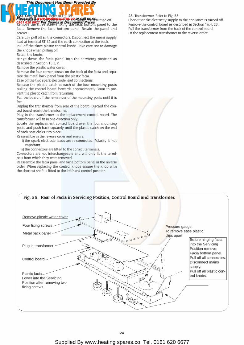
223. Control Board. Refer to Fig. 35.Check that the electricity supply to the appliance is turned off.Remove the three screws fixing the facia bottom panel to thefacia. Remove the facia bottom panel. Retain the panel andscrews.Carefully pull off all the connectors. Disconnect the mains supplylead at terminal ST 12 and the earth connection at the back.Pull off the three plastic control knobs. Take care not to damagethe knobs when pulling off.Retain the knobs.Hinge down the facia panel into the servicing position asdescribed in Section 15.3, c.Remove the plastic water cover.Remove the four corner screws on the back of the facia and sepa-rate the metal back panel from the plastic facia.Ease off the two spark electrode lead connections.Release the plastic catch at each of the four mounting postspulling the control board forwards approximately 3mm to pre-vent the plastic catch from returning.Pull the board off the remainder of the mounting posts until it isfree.Unplug the transformer from rear of the board. Discard the con-trol board retain the transformer.Plug in the transformer to the replacement control board. Thetransformer will fit in one direction only.Locate the replacement control board over the four mountingposts and push back squarely until the plastic catch on the endof each post clicks into place.Reassemble in the reverse order and ensure:
i) the spark electrode leads are re-connected. Polarity is notimportant.
ii) the connectors are fitted to the correct terminals. Connectors are not interchangeable and will only fit the termi-nals from which they were removed.Reassemble the facia panel and facia bottom panel in the reverseorder. When replacing the control knobs ensure the knob withthe shortest shaft is fitted to the left hand control position.
23. Transformer. Refer to Fig. 35.Check that the electricity supply to the appliance is turned off.Remove the control board as described in Section 16.4, 23.Pull the transformer from the back of the control board.Fit the replacement transformer in the reverse order.
24
Fig. 35. Rear of Facia in Servicing Position, Control Board and Transformer.
Remove plastic water cover
Four fixing screws
Metal back panel
Plug in transformer
Control board
Plastic facia.Lower into the ServicingPosition after removing twofixing screws
Pressure gauge. To remove ease plasticclips apart
Before hinging faciainto the ServicingPosition remove:Facia bottom panelPull off all connectors.Disconnect mains supply.Pull off all plastic con-trol knobs.
Supplied By www.heating spares.co Tel. 0161 620 6677
25
17. Short Parts List
G.C.No. Part WHS Part No.E01 064 BF Standard Terminal 225mm- 420mm 7 716 191 007E01 065 BF Extended Terminal 420mm- 560mm 7 716 191 008299 361 Digital Single Channel Programmer 7 716 192 003299 360 Mechanical Single Channel Programmer 7 716 192 002E01 053 Digistat CD (Radio Controlled Room Thermostat) 7 716 192 006E00 748 BF Open Vent Kit 7 716 192 108
Pre-system Filling Loop 7 716 192 102Mini Expansion Vessel 7 716 192 105
Acccessories For 24CDi BF
Key G.C. No. Part Manufacturer’s Reference Qty WHSNo. Part No.
26 E80 450 Gas Valve – Natural Gas Dungs BM771 SL040 1 8 716 102 673 078 375 695 Burner – Natural Gas Aeromatic, ref. AC 23/05 3582 1 8 716 142 602 080 173 091 Burner Injector – Natural Gas Stereomatic, type 7, 4.5mm dia. 1 8 716 140 208 081 375 697 Spark Electrode Assembly Buccleuch, ref. BE/3462/SI 1 8 716 142 100 082 E01 612 Flame Sensor Buccleuch, ref. BE/3461/SI 1 8 716 120 345 095 299 515 Ignition Harness Buccleuch, ref. BE/3469/SI 1 8 716 120 229 061 299 352 Gas to Water Heat Exchanger Giannoni, ref. PR22 323 003, spec. D2107 1 8 716 142 800 068 E00 716 Automatic Air Vent Intermes, ref. 02.05.010 1 8 716 140 500 085 299 506 System Pressure Gauge Cewal, spec. D2111 1 8 716 142 300 040 375 699 Pressure Relief Valve Caleffi, ref. 312439 1 8 716 142 404 029 173 006 Circulating Pump Grundfoss, ref. 50 50 6601 1 8 716 143 100 025 173 001 Expansion Vessel Zilmet, ref. 301010 1 8 716 142 500 042 299 353 Water to Water Heat Exchanger Giannoni, ref. PVW 12 E, spec. D2108 1 8 716 142 900 034 173 005 Diverter Valve Giannoni, ref. V37/OM/I/F/4/A spec D2109 1 8 716 142 401 0
104 379 215 DHW Flow Restrictor Type E - White 1 8 716 141 054 0105 378 416 Domestic Water Filter MPM, V3326 1 8 716 148 400 0109 E01 840 Charging Link Assembly WHS 1 8 716 120 320 084 173 014 Circuit Board – OF/BF Junkers Bosch, type Heatronic II KE 1 8 748 300 220 096 299 516 Transformer ERA, Ref. BV 066-0188.0 1 8 747 201 248 060 375 696 Thermister Sensor Elmwood, ref. 6655 - 9003 - 5 2 8 716 142 302 062 173 015 Overheat Thermostat Elmwood, ref. 2455 R - 98 - 789 1 8 716 142 303 0
133 299 354 Combustion Chamber Insulation Pack WHS 1 7 716 192 204 0134 299 355 Fibre Washer Pack WHS 1 7 716 192 205 0135 299 356 ‘O’ Ring Pack WHS 1 7 716 192 207 0136 299 357 Fuse Pack WHS 1 7 716 192 206 0
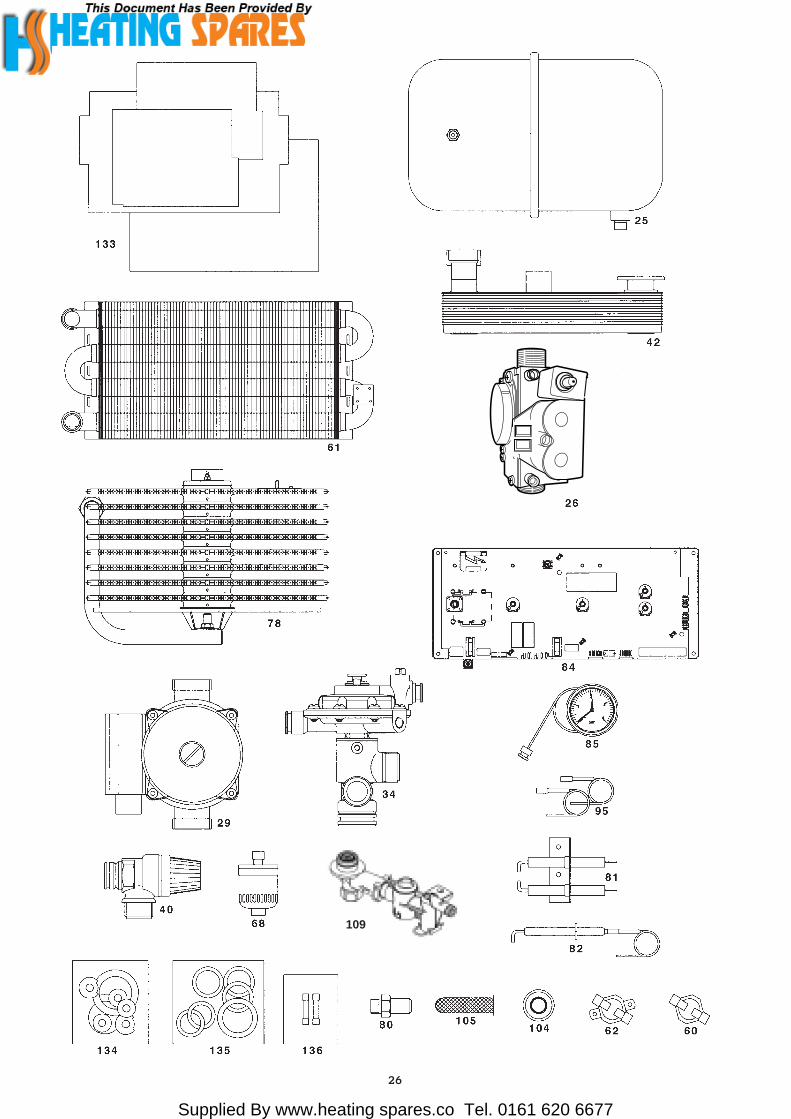
Supplied By www.heating spares.co Tel. 0161 620 6677
26
109
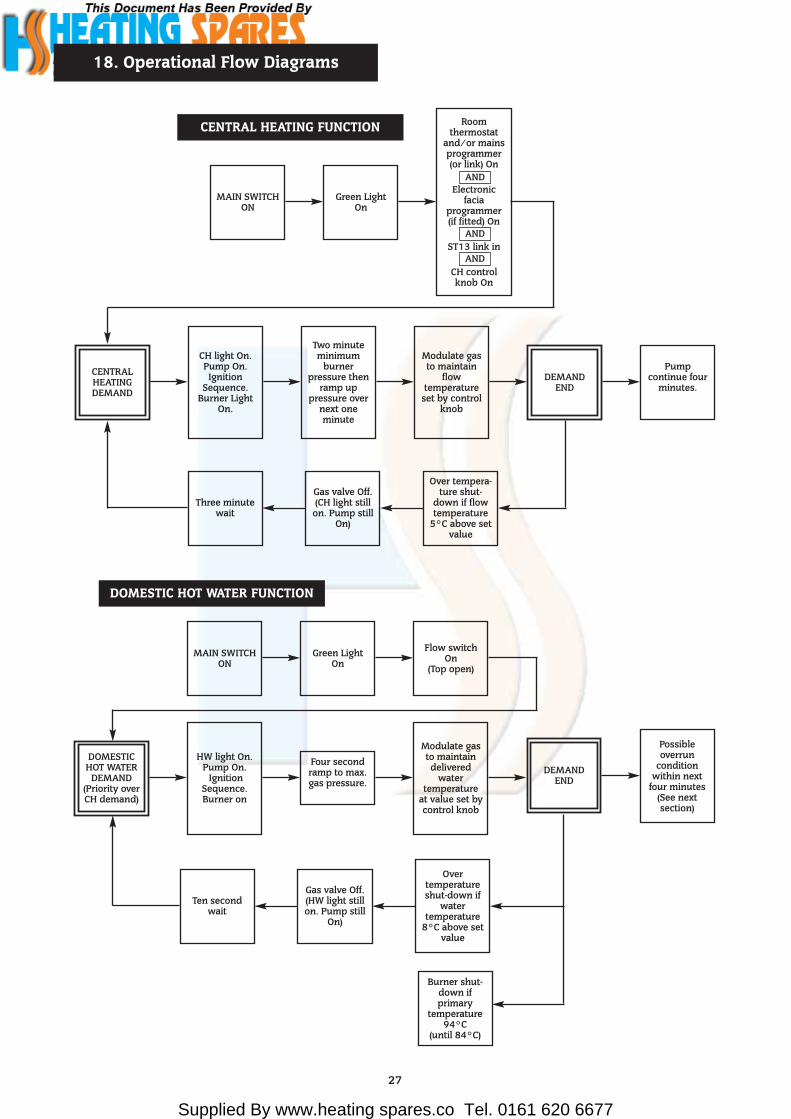
Supplied By www.heating spares.co Tel. 0161 620 6677
27
18. Operational Flow Diagrams
MAIN SWITCHON
Green LightOn
Roomthermostat
and/or mainsprogrammer(or link) On
ANDElectronic
faciaprogrammer(if fitted) On
ANDST13 link in
ANDCH controlknob On
CENTRALHEATINGDEMAND
CH light On.Pump On.Ignition
Sequence.Burner Light
On.
Three minutewait
Gas valve Off.(CH light still
on. Pump stillOn)
Over tempera-ture shut-
down if flowtemperature
5°C above setvalue
Two minuteminimum
burnerpressure then
ramp uppressure over
next oneminute
Modulate gasto maintain
flowtemperature
set by controlknob
DEMANDEND
Pumpcontinue four
minutes.
CENTRAL HEATING FUNCTION
AND
AND
AND
DOMESTIC HOT WATER FUNCTION
MAIN SWITCHON
Green LightOn
Flow switchOn
(Top open)
DOMESTICHOT WATER
DEMAND(Priority overCH demand)
HW light On.Pump On.
IgnitionSequence.Burner on
Four secondramp to max.gas pressure.
Modulate gasto maintaindelivered
watertemperature
at value set bycontrol knob
Ten secondwait
Gas valve Off.(HW light stillon. Pump still
On)
Overtemperatureshut-down if
watertemperature
8°C above setvalue
Burner shut-down ifprimary
temperature94°C
(until 84°C)
DEMANDEND
Possibleoverrun
conditionwithin next
four minutes(See nextsection)

Supplied By www.heating spares.co Tel. 0161 620 6677
28
Above9°C
Commence normalcentral heating mode
until temperaturereaches 30°C
5°Cto
9°C
Below5°C
No demandand primarytemperaturebelow 8°C
Internal“Autofrostat”
demand
Wait in normaloff state for30 minutes
Run pump forfour minutes
Monitorcentralheatingsensor
Return tonormal off
state
AUTOFROSTAT FUNCTION

Supplied By www.heating spares.co Tel. 0161 620 6677
29
Note: This fault-finding information is for guidance only. Worcester Heat Systems cannot be held responsible for costs incurred bypersons not deemed to be competent.The electronic control system for this boiler incorporates four lights on the facia. These are used to show normal operating status. But asa secondary function, by flashing, they can also be used to help provide fault diagnostics. Therefore, with individual or groups of lightsbeing permanently off, on or flashing, every normal fault can be identified.To use the fault finding system, select a box below which represents the light situation during your fault. Then refer to the appropriatefollowing section. This fault-finding system assumes that the appliance has been operating correctly until the time of failure.PRELIMINARY CHECKSPreliminary electrical system checks are the first electrical checks to be carried out during a fault-finding procedure. On completion ofthe Service/Fault-Finding task which has required the breaking and remaking of electrical connections, check (a) EARTH CONTINUITY,(b) SHORT CIRCUIT CHECK, (c) POLARITY and (d) RESISTANCE TO EARTH.
Note:Slow flash is once per second, fast flash is five times per second.Slow flash can only be cleared by using the facia reset button (press for at least one second).Fast flash is cleared by removing fault and/or main switch off/on.
19. Fault Finding
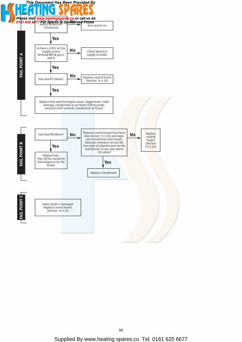
Supplied By www.heating spares.co Tel. 0161 620 6677
30
Is the facia on/offswitch turned on?
`(Clockwise)
Is there a 230V AC livesupply across
Terminal ST12 pins Land N
Has fuse F1 blown?
Replace fuse and investigate cause. Suggestions: Cabledamage, connections to (or faults within) pump,
external 230V controls, transformer or board.
Turn switch on.
Check electricalsupply to boiler.
Replace control board(Section 16.4.22)
FAIL
PO
INT
ANo
No
Yes
Yes
Yes
No
Replace fuse.This will be caused byfuse fatigue or by the
board.
Has fuse F2 blown? Replacecontrolboard
(Section16.4.22).
Remove control board from facia(See Section 16.4.22) and sepa-
rate transformer from board.Measure resistance across the
two pairs of adjacent pins on thetransformer. Is any pair above
100 ohms?
Replace transformer.
FAIL
PO
INT
B
No No
Yes
Yes
Green diode is damaged.Replace control board.
(Section 16.4.22)
FAIL
PO
INT
C

Supplied By www.heating spares.co Tel. 0161 620 6677
31
Red diode isdamaged. Replace
control board.(Section 16.4.22)
Is there a link atterminal ST13 pins 1
and 2?
Is there an electronicprogrammer at
position ST5 at right-hand end of board?
Replace control board.(Section 16.4.22).
With CH control knobfully clockwise, doesthe boiler ignite and
appear to runnormally in central
heating mode?
Is there 230V ACacross terminal ST8
pins LR and N?
There is no heatdemand. Check roomthermostat or mainsprogrammer (or link).
Insert a link
FAIL
PO
INT
DNo No
No
No
No
Yes
Yes
Remove programmerconnector from boardedge. Does CH lamp
now light?
Yes
Correctly set orreplace electronic
programmer.
Yes
Yes
Red diode isdamaged. Replace
control board.(Section 16.4.22)
Replace control board.(Section 16.4.22).
With a hot water tapfully open, does the
boiler ignite andappear to run
normally in hot watermode?
Remove multiwayconnector from boardposition ST16. Withtap still open is there
continuity acrosscontacts 19 and 20
(2 pink wires)?
Remove the black coverfrom the microswitch
assembly. With tap stillopen is there continuity
between the twoconnected terminals
(C and NO)?
Visually observe if theplunger on the diverter
valve assembly is pushingthe microswitch button(Note: May be helpful iftap is repeatedly turned
on and off). If plungermoves replace
microswitch (Section16.4.15). If plunger doesnot move replace water
diverting valve.(Section 16.4.16).Repair or replace
wiring/harness
FAIL
PO
INT
E
No No No
Yes Yes Yes

Supplied By www.heating spares.co Tel. 0161 620 6677
32
Boiler is running in“Autofrost stat” mode.
See Section 18.
Replace control board.(Section 16.4.22).Note: A wet board
could cause this fault.
Is the boiler in a verycold environment (less
than 5°C)?
Drop down the facia.Is the gas valve modeswitch in the normal
position?
Turn to normalposition.
FAIL
PO
INT
FNo No
Yes Yes
Is the boiler fullywater pressurised and
is all air vented?Rectify fault.
FAIL
PO
INT
G “P
rim
ary
Ove
rhea
t”
No
Re-fix sensor to pipe.No
Repair or replacepump.
(Section 16.4.12).
NoReset the controls andrestart the boiler.
Does the pump run?
Yes
Remove inner casingcover and inspect theprimary sensor (left of
heat exchanger).Is it correctly fixed to
pipe?
Yes
Fault caused by controlboard or primary heat
exchanger.
Yes
Remove the multiwayconnector from board
position ST16.Is there a short circuitacross contacts 5& 6?
Yes
Replace overheatthermostat or check
wiring to it.
No

Supplied By www.heating spares.co Tel. 0161 620 6677
33
Remove front panel.Reset and restart theboiler. Can a flame beseen through the spy
glass?
Turn off boiler. Removeinner cover and
combustion chambercover. Is the sense
electrode and lead ingood condition and is
gap correct.
Remove multiwayconnector from board
position ST16.Is there continuity
from contact 11 (whitewire) to flame sensor?
Does the flashing faultsignal occur at thestart of a demand?
Replace control board (Section 16.4.23).Note: It is not possible to reliably check
the cross-light performance of the burner.In the unlikely event of such a fault,investigate flue problems or replace
burner or injector. (Section 16.4.5/6).
Flashing occurs at endof demand. Replace
gas valve.(Section 16.4.9).
Remove inner cover.Reset and restart theboiler. Does a spark
occur across theelectrodes?
Turn off boiler. Removethe multiway
connector from boardposition ST16. Testresistance acrosscontacts 7 and 8
(brown wires) and 9and 10 (violet wires).
Are both readingbelow 100 ohms?
Replace control board.(Section 16.4.22).
Repair or replace flamesensor
(Section 16.4.8)or wiring.
Replace gas valve.(Section 16.4.9).
Are the electrodes andgap and connections
in good order?
Replace control board.(Section 16.4.22).
Remove both brownconnectors from gas
valve.Is there continuity
from brown and violetwires to multiway
connector?
Repair or replaceharness.
Repair or replacespark electrode(Section 16.4.7)
or HT leads
Is the gas supplyconnected and at the
correct pressure?
Rectify gas supplyproblem.
FAIL
PO
INT
H “
Burn
er L
ocko
ut”
No
No No
No
No
No
No
No
No
Yes
Yes
Yes
Yes
Yes
Yes
Yes
Yes
Yes

Supplied By www.heating spares.co Tel. 0161 620 6677
34
Remove multiwayconnector from board
position ST16. Testresistance across
contacts 17 and 18(yellow wires). Is it
between 1 kohm and30 kohm?
Test resistance acrosscontacts 12 and 13
(red wires). Is itbetween 1 kohm and
30 kohm?
Test resistance acrosscontacts 7 and 8
(brown wires) and 9and 10 (violet wires).
Are both readingsbelow 100 ohms?
Replace control board.(Section 16.4.23).
Replace gas valve.(Section 16.4.9).
Remove both brownconnectors from gas
valve. Is therecontinuity from
brown and violetwires to the multiway
connector?
Check or replace CHsensor.
(Section 16.4.10).
Is there continuityfrom contacts 17 and18 to DHW sensor?
Check or replaceDHW sensor.
(Section 16.4.11).
Is there continuityfrom contacts 12 and
13 to CH sensor?
Repair or replaceharness.
Repair or replaceharness.
Repair or replaceharness.
Is the multiwayconnector at board
position ST16 pushedfully home on to the
board?
Push fully home.
FAIL
PO
INT
I “Se
nsor
Fau
lt”No
No
No
No
No
No
No
Yes
Yes
Yes
Yes
Yes
Yes
Yes
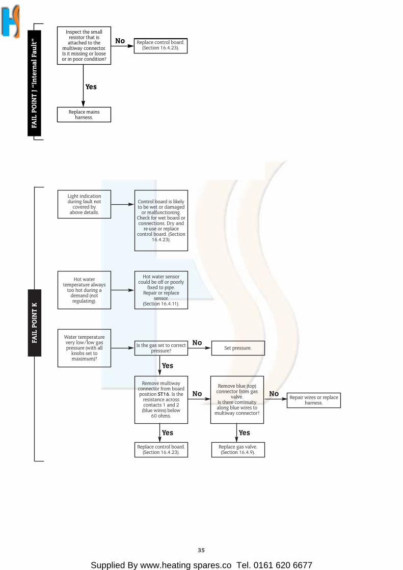
Supplied By www.heating spares.co Tel. 0161 620 6677
35
Light indicationduring fault not
covered byabove details.
Control board is likelyto be wet or damaged
or malfunctioning.Check for wet board orconnections. Dry and
re-use or replacecontrol board. (Section
16.4.23).
FAIL
PO
INT
K
Hot watertemperature always
too hot during ademand (notregulating).
Hot water sensorcould be off or poorly
fixed to pipe.Repair or replace
sensor.(Section 16.4.11).
Water temperaturevery low/low gaspressure (with all
knobs set tomaximum)?
Remove multiwayconnector from boardposition ST16. Is the
resistance acrosscontacts 1 and 2
(blue wires) below60 ohms.
Remove blue (top)connector from gas
valve.Is there continuityalong blue wires to
multiway connector?
Is the gas set to correctpressure? Set pressure.
No
No Repair wires or replaceharness.
No
Yes
Yes
Replace gas valve.(Section 16.4.9).
Replace control board.(Section 16.4.23).
Yes
Inspect the smallresistor that isattached to the
multiway connector.Is it missing or looseor in poor condition?
Replace control board.(Section 15.4.20).
Replace mainsharness.
FAIL
PO
INT
J “In
tern
al F
ault” No
Yes
Replace control board.(Section 16.4.23).
Supplied By www.heating spares.co Tel. 0161 620 6677
This booklet is accurate at the date of printing but will be superseded and should be disregarded if specifications and/or appearances are changed in the interestsof continued improvement.
All goods sold are subject to our official Conditions of Sale, a copy of which may be obtained on application.
PUBLICATION 8 716 115 053a (05/08)
Worcester Heat Systems Limited, Cotswold Way, Warndon, Worcester WR4 9SW.Telephone: (01905) 754624. Fax: (01905) 754619.
Technical Helpline 08705 266241.www.worcester-bosch.co.uk
This manual is to be used in conjunctionwith the variant part number of the barcode below: