wooden gear clocks ukstratta.net/grandes/crokerel.pdf · 2013-06-08 · thank you for purchasing...
TRANSCRIPT
Wooden Gear Clocks UK 316 Pickering Road, Hull, East Yorkshire, UK Tel 01482 509277
http://wooden-gear-clocks.co.uk/
Build Manual for “Clockerel” Electromechanical Wooden Geared Clock
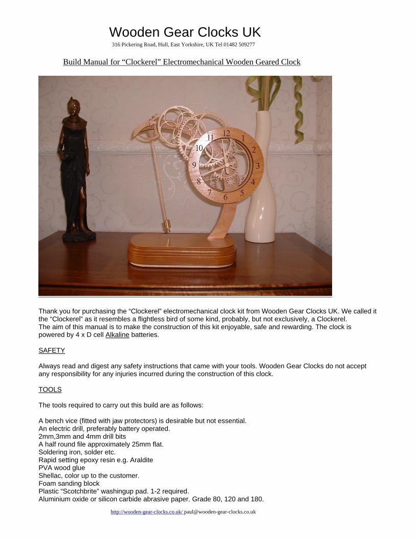
Thank you for purchasing the “Clockerel” electromechanical clock kit from Wooden Gear Clocks UK. We called it the “Clockerel” as it resembles a flightless bird of some kind, probably, but not exclusively, a Clockerel. The aim of this manual is to make the construction of this kit enjoyable, safe and rewarding. The clock is powered by 4 x D cell Alkaline batteries. SAFETY Always read and digest any safety instructions that came with your tools. Wooden Gear Clocks do not accept any responsibility for any injuries incurred during the construction of this clock. TOOLS The tools required to carry out this build are as follows: A bench vice (fitted with jaw protectors) is desirable but not essential. An electric drill, preferably battery operated. 2mm,3mm and 4mm drill bits A half round file approximately 25mm flat. Soldering iron, solder etc. Rapid setting epoxy resin e.g. Araldite PVA wood glue Shellac, color up to the customer. Foam sanding block Plastic “Scotchbrite” washingup pad. 1-2 required. Aluminium oxide or silicon carbide abrasive paper. Grade 80, 120 and 180.

Wooden Gear Clocks UK 316 Pickering Road, Hull, East Yorkshire, UK Tel 01482 509277
http://wooden-gear-clocks.co.uk/
Aerosol can of automotive clear spray lacquer (Acrylic). Jig as drawing Clockerel-0016 Flat 300mm steel rule Sharp knife/scalpel SKILLS A knowledge of basic wood finishing techniques and the ability to read drawings. Basic soldering skills are also required, but not essential as you could always get someone with the skills to perform these tasks. Six soldered joints are required to complete the clock. These instructions are to be read in conjunction with drawings Clockerel-0001 to 0017. PARTS Please check all parts against the parts list (BOM). If any parts are missing then please contact us immediately. Disregard any dimensions given verbally in the build video as designs change. Use drawings only. The assembly order in the video may not be as these instructions. INSTRUCTIONS 1. Drawing Clockerel-0001/0002
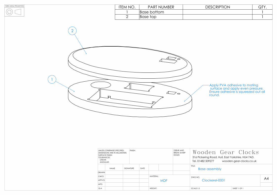
Trial fit the frame into the base. If it is too tight to push in easily by hand then remove a small amount of MDF from the frame until a smooth push fit is achieved. This is best done with the file or a sharp edged knife. Apply PVA adhesive to one of the mating surfaces of the base and press together with the other part . Place the base on a flat surface with a heavy object to sandwich the assembly. Alternatively use clamps with protection to prevent damage to the surfaces. Ensure that the two parts are correctly aligned around the edges and that adhesive has squeezed out all round. This ensures that there are no dry voids around the edge which would show up during finshing. Leave for 4 hours and then finish as per preparation of the MDF parts.
2. Preparation of parts
MDF parts: It is very important that the edges of these parts are well sanded to a smooth finish. The finish of the edges will reflect in the overall appearance of the clock. All machining marks and adhesive MUST be removed with 80 grade abrasive paper or the edge of the file as shown in my video. Only sand/file in the direction of the edge, NOT across it. Sanding across the edge could break away the veneer as well as not giving a good finish. Work your way down to the 180 grade paper and finish with a fine foam sanding pad or Scotchbrite. The edges should now be smooth with an even texture. The veneered side can be sanded with just the 180 grade abrasive paper and Pad/Scotchbrite, working in the direction of the grain. Only a light sanding is required. After preparation apply shellac to all exterior surfaces and sand with a Pad/Scotchbrite when dry, paying particular attention to the edges. Repeat this process until the edges are smooth with an even dark texture (approximately 4/5 times). The MDF parts can now be finished with clear acrylic applied in several light coats with sanding in between.
Plywood parts:
The faces should be carefully sanded with 180 grade abrasive paper wrapped around a sanding block. Lay the parts on a flat surface and carefully sand the faces in the direction of the grain. The faces can also be sanded by gluing a sheet of 180 grade to a flat surface and rubbing the parts on this. Wrap a small amount of 180 grade paper into the size of a flattened cigarette to do the inner edges and teeth. Only sand the teeth to remove ragged edges. DO NOT sand too much as the profile of the teeth may be effected. The faces of the parts may be treated with shellac as above if required.

Wooden Gear Clocks UK 316 Pickering Road, Hull, East Yorkshire, UK Tel 01482 509277
http://wooden-gear-clocks.co.uk/
The spacers can be inserted onto to the 3mm mandrill supplied and sanded using a battery drill and abrasive paper. The spacers should be trial fitted to the shafts. They should be tight but not so tight that they cannot be moved with finger pressure. If they are too tight then enlarge the hole with the 3mm drill. Twist the spacers onto the drill in a counter clockwise direction so that the faces are not split. If you drill into the in a conventional direction the faces will be damaged. You can now enlarge the hole by holding the spacer and sliding the drill bit up and down. Brass shafts: The shafts should be cut to the required length (5 in all). I am unable to get brass rod that fits with the required tolerances to the bearings. The shafts should be a smooth sliding fit in the bearings. This makes subsequent assembly much easier and prevents damage to the parts. Put a shaft into the battery drill and sand with 120 grade abrasive for about 5 seconds, moving the abrasive up and down the shaft. Finish with 180 grade and trial fit to the bearing. Repeat until the required fit is achieved. Repeat for the other end.
3. Drawing Clockerel-0002
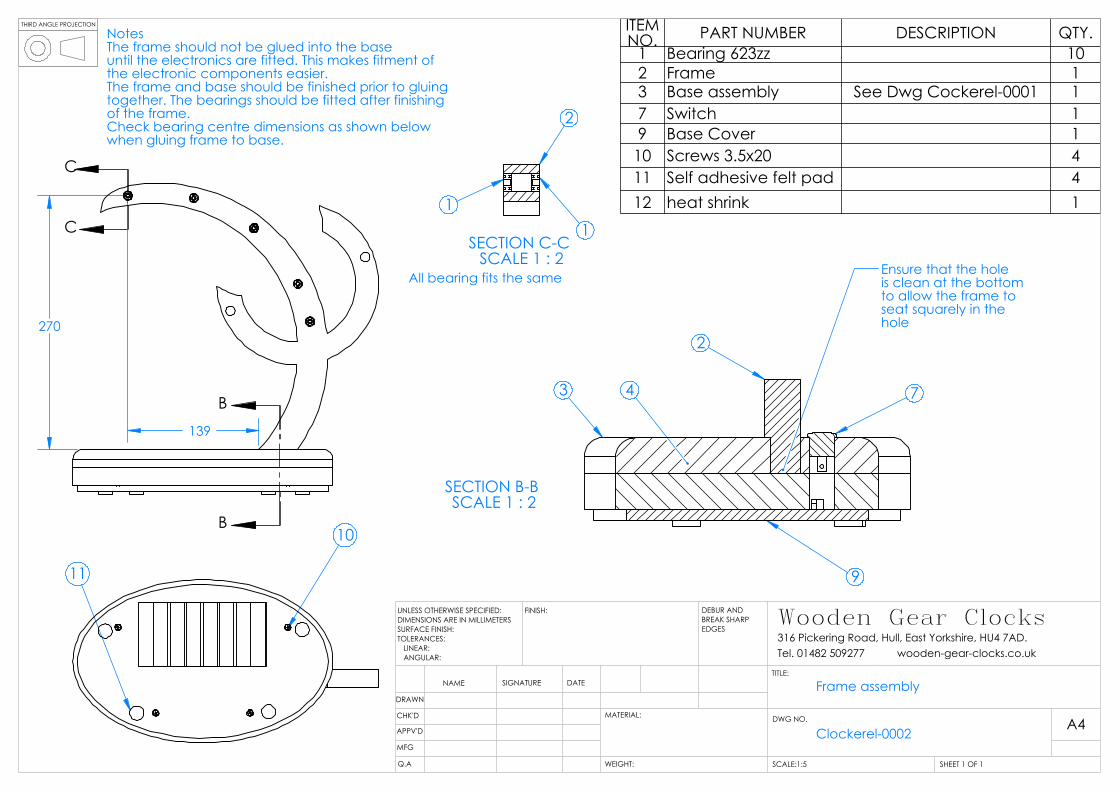
When the desired finish has been achieved the bearings can be fitted into the holes as shown in section C-C. The bearings should be pressed partly into the holes using finger pressure. If they are too tight then lightly sand the inside of the holes until the desired fit is achieved. Push the bearings fully home with the flat side of a 25mm wide steel rule or similar. This ensures that the bearings are square and flush with the face of the frame. Stick the pads to the base (ensure it’s the right side) and temporarily attach the base cover to the base with the 4 screws provided. Carry out instruction 4 before gluing the frame to the base. Ensure that the hole for the frame is clear and temporarily fit the frame to the base. The hole in the base is 6mm longer than the adjoining piece of the frame. Therefore the frame requires fitting central in the hole. Check that the pendulum bearing is approximately 139mm from the base when measured at 90 degrees from the base. When happy a small amount of epoxy can be put around the hole and the parts fixed permanently.
4. Clockerel-0003/0004
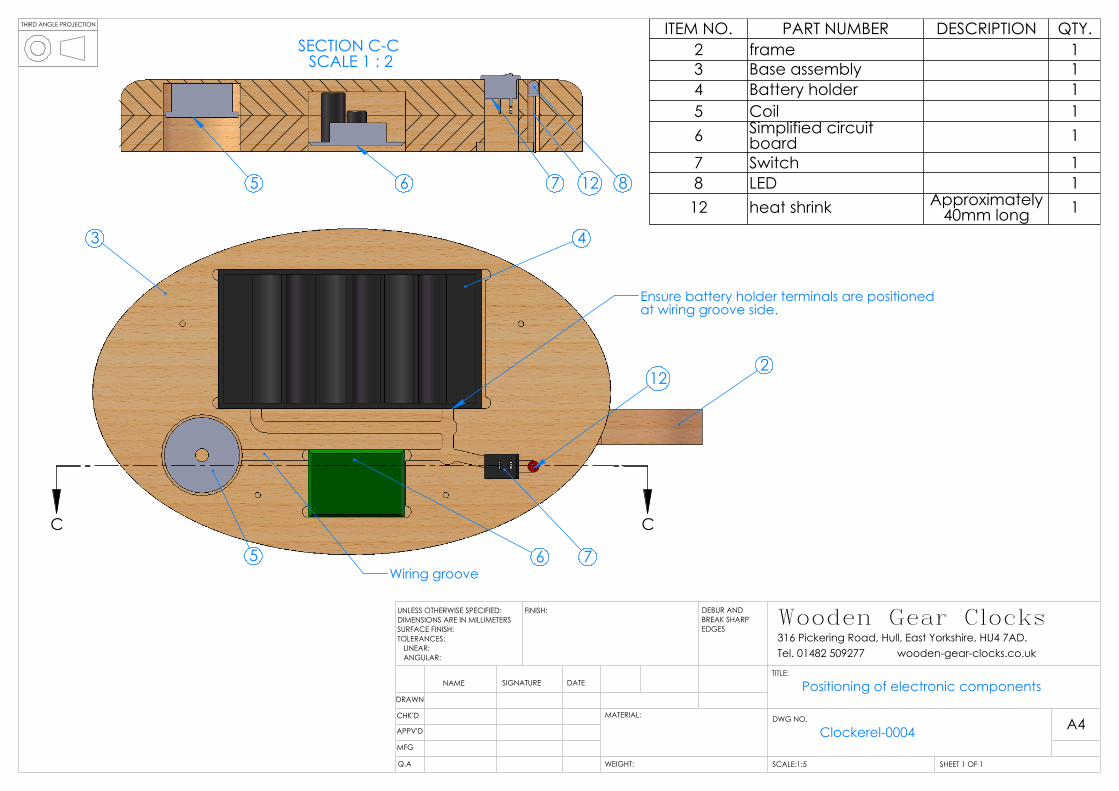
The electrical components should now be installed. Remove the base cover and place the base inverted onto the work surface. Cover the work surface with a towel or similar to protect the base finish and switch after installation Cut 1 piece of red wire 165mm long and 1 piece 250mm long. Solder these to the switch terminals and install into the frame with the wires passing through the hole. Cut 1 piece of black wire 125mm long and solder this to the negative terminal of the battery box. Ensure that the wire orientation is such that the wire will be pointing the correct direction when the battery box is installed. Cut 1 piece of red wire 100mm long and 1 piece of black wire 100mm long. Solder the red wire to the longer terminal of the LED and the black wire to the shorter terminal. Push a piece of the heat shrink material over one of the terminals to prevent a short circuit between the terminals. Shrink this on with a cigarette lighter, being careful not to burn it. Insert the switch into the base. Solder the longer wire to the battery box positive terminal ensuring the correct orientation. The battery box can now be fitted. Insert the LED into the hole in the base. This hole may require cleaning as glue can enter it during the base assembly. Place the LED to the depth you prefer. Place the coil into the frame recess paying attention to the orientation shown in drawing Clockerel-0004. Burn or sand the lacquer from the coil terminals and connect these to the 2 center terminals of the circuit board. Connect the LED wires as shown in the wiring schematic. Connect the black wire from the battery box and the red wire from the switch to the circuit board as shown. Be careful to get these the correct way round. The circuit board is not polarity protected due to resistance issues. Incorrect connection would damage the board.

Wooden Gear Clocks UK 316 Pickering Road, Hull, East Yorkshire, UK Tel 01482 509277
http://wooden-gear-clocks.co.uk/
Insert the circuit board into the base as shown. Cut a piece of foam to the correct length to keep the coil in place. Masking tape may be used to keep the wires in the wiring grooves during installation. Reassemble the cover to the base.
5. Clockerel-0009 / 30 tooth wheel assembly
Inset the shaft 1 through the 3mm hole in the jig allowing 6mm to protrude (use wheel to measure this). Place a small amount of epoxy inside the hole of part 2 and not on the shaft. This ensures that oozing adhesive does not cause the part to stick to the jig. Place the wheel over the shaft ensuring that the best side faces towards the front of the clock. Remove the part from the jig by pushing on the rod from beneath and not by pulling the wheel. Remove it when the remaining mixed adhesive has dried. Now place a small amount of adhesive on the shaft adjacent to and on part 2. Slide part 3 down the shaft and into position. Allow to dry. This method of assembly ensures that adhesive does not get on the shaft. When the assembly is fully dried, slide part 3 down the shaft. Place a small amount of epoxy onto the mating face of part 4 being careful not to get any into the hole. Push part 4 fully onto the shaft and slide part 3 back up to adhere to it. Leave until remaining epoxy mix has almost dried and then carefully withdraw from the shaft without misaligning the parts. Allow it to dry thoroughly. Remove any epoxy from the end of the shaft which may have leaked out. The part can now be fitted to the clock temporarily with the 2 washers (5). The part should have approximately 1mm of end float (side to side movement) when assembled in the frame. File the end of the shaft until the desired end float is achieved. Ensure that part 4 is fitted fully onto the shaft. The part should spin freely.
6. Clockerel-0008 / 60 tooth wheel assembly Repeat the basic assembly instructions as above for the 30 tooth wheel assembly.
7. Clockerel-0011 / 64 tooth wheel assembly
Repeat the instructions as above for the 30 tooth wheel assembly and the 60 tooth wheel assembly. This assembly cannot be adjusted for end float until the final assembly.
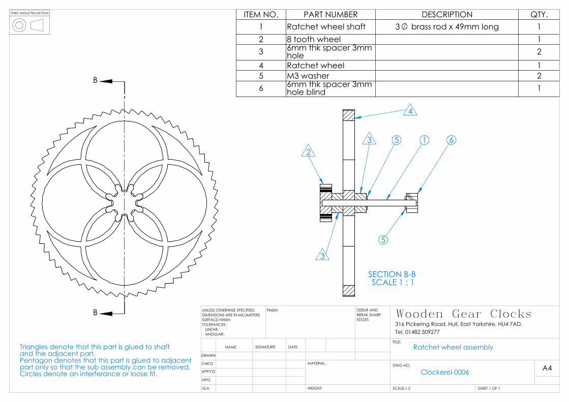
8. Clockerel-0006 / Ratchet wheel assembly
Place the shaft into the jig with approximately 15mm of shaft protruding. Place a small amount of epoxy into the hole of the ratchet wheel (part 1) with a cocktail stick or similar. Slide the ratchet wheel onto the shaft making sure it is fitted the correct way round. It should feel rough when you rotate your finger around the edge in a clockwise direction. Place a small amount of epoxy onto the spacer (part 3) and slide into position whilst holding the shaft. Place a small amount of epoxy onto the 8 tooth wheel (part 2) and slide into position. Ensure that part 2 is fully fitted by pushing the shaft upwards whilst pushing part 2 downwards. Leave it to dry. Remove from the jig as previously described and place a small amount of epoxy onto the mating face of part 4. Push part 3 into position until full home. The part can now be fitted to the clock temporarily with the 2 washers (5) and part 6. The part should have approximately 1mm of end float (side to side movement) when assembled. File the end of the shaft until the desired end float is achieved. Ensure that part 6 is fitted fully onto the shaft. The part should spin freely.
9. Clockerel-0005 / Pendulum pawl assembly
Insert the pawl pin (part 10) into the assembly jig with just over 6mm protruding. Place a small amount of epoxy resin into the smaller hole in the drive pawl lever (part 3). Push this over the pin paying attention to the orientation. Leave the part to dry and remove from the jig. Place a small amount of epoxy resin inside the largest hole of the Non return pawl (part 5). The amount of resin should just be enough to wet the surface and no more. Excess could be squeezed onto the

Wooden Gear Clocks UK 316 Pickering Road, Hull, East Yorkshire, UK Tel 01482 509277
http://wooden-gear-clocks.co.uk/
bearing seal. Push the bearing into the hole making sure it is square to the face. To ensure it is square after insertion, lay the part onto a flat surface and push the bearing down onto the same surface. Glue the blind spacer (part 2) onto the end of the pendulum shaft (part 1). When this has dried the part 2 can be sanded by placing the shaft into the drill. Check that no adhesive remains on the face or shaft. Remove if necessary. Place a small amount of adhesive onto part 2 and the adjacent 3mm of shaft. Slide the drive pawl lever onto the shaft and into position. Leave it to dry. Place the drive pawl (part 4) over the pin in part 3. Check that it is free to rotate on the shaft. If not then open the hole carefully with a 2mm drill. Again insert in a counter clockwise direction. When free to rotate, assemble onto the shaft with the retainer (part 11). Some end float is required for free movement. Place a washer over the shaft 1 followed by part 5 as shown. A further 4 washers are placed along the shaft followed by part 6. Part 5 should pivot freely at this point as the washers should ensure clearance between it and the adjacent parts. If it does not pivot freely check the bearing 8 for freedom of rotation. The part can now be fitted to the frame with the 2 washers (9) and the part 7. Check for 1mm end float and adjust shaft length as necessary.
10. Clockerel-0010 / Hour hand assembly
Cut part 1 to length. Make this part 48mm long. Clean the inside of the tube where it has been cut to remove any rough edges. Insert the tube into the assembly jig allowing approximately 12.5mm to protrude. Place a small amount of epoxy resin inside the hole in the 32 tooth wheel (part 4). Slide the wheel (part 4) over the tube until flush with the jig ensuring the best side faces the front of the clock. Approximately 6.5mm of tube should now be protruding from the gear wheel 4. Some epoxy will run inside the tube but this can be removed with a 3mm drill when dry. Allow the part to dry and remove from the jig. Check that the 4mm spacers (part 3) fit onto the tube. If they are too tight then open the hole slightly with a 4mm drill until a sliding fit on the tube. Place a small amount of epoxy onto the 32 tooth wheel where the adjoining spacer will touch and push the spacer onto the tube. Repeat for the other 3 spacers and allow it to dry. The spacers can now be sanded smooth by inserting the assembly on to the mandrill and into the battery drill. Do not tighten the mandrill too much as this can distort the tube. Glue the hour hand (part 2) onto the tube orientating it in a non random position. Follow this by the last spacer. Set the assembly aside.
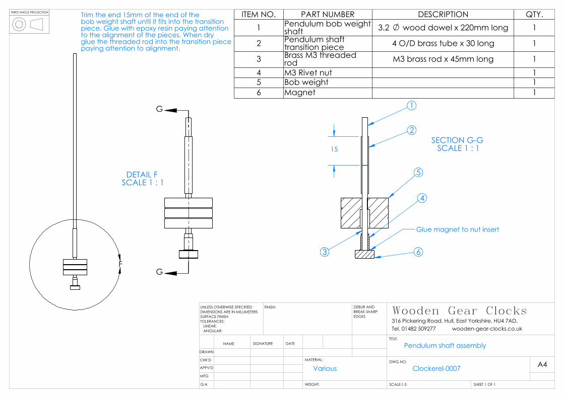
11. Clockerel-0007 / Pendulum shaft assembly
Cut part 1 to 220mm from the 1/8” wooden dowel. Cut part 2 to 30mm from the 4mm OD tube and part 3 to 45mm from the M3 brass rod. Mark 15mm along the wooden dowel and reduce the diameter of this section until it fits tightly into part 2. Glue these two parts together paying particular attention to the alignment. When dry glue part 3 into part 2, again paying attention to alignment. Glue the magnet (part 6) onto the Rivet nut (part 4). Set the assemblies aside to dry. When dry, screw part 4 onto part 3 approximately 3 turns. Adjust the length of the wooden shaft so that the magnet just clears the base when the shaft is pushed into the pendulum mount.
12. Clockerel-0013 / Face assembly
Cut the 9mm dowel into 2 lengths each 58mm long (2). Sand each end until it is a sliding fit into the frame and the face. Glue the dowels into the face as shown.
Set the assembly aside. 13. Clockerel-0014 / Clockerel assembly exploded.

Wooden Gear Clocks UK 316 Pickering Road, Hull, East Yorkshire, UK Tel 01482 509277
http://wooden-gear-clocks.co.uk/
Remove all parts from the clock which may have been temporarily assembled. Insert 4 x D cell batteries into the clock and switch off. Ensure Alkaline batteries are used and that they are fitted correctly (Polarity). As stated earlier the clock has no polarity protection as this would result in a reduced battery life. Insert the ratchet wheel assembly 1 into the bearings as shown. Ensure that the 2 washers are inserted either side on the bearings. Insert the 60 tooth wheel assembly 2 into the bearings as shown. Ensure that the washers are inserted either side of the bearings. Insert the 30 tooth wheel assembly 4 into the bearings as shown. Ensure that the washers are inserted either side of the bearings. Insert the 64 tooth wheel assembly 3 into the bearings as far as the second bearing. Ensure that the washer was inserted on the shaft before this operation. Position the hour hand assembly 5 into position under the 60 tooth wheel. Slide the 64 tooth wheel the remainder of the way and into the hour hand assembly. The face assembly 8 can now be fitted. The face should have a standoff from the 60 tooth wheel of approximately 3mm as shown in Clockerel-0015. Reduce the length of the dowels if necessary. The minute hand can now be fitted as shown. The hour hand assembly should have approximately 1mm of end float on the shaft. Adjust the length of the 64 tooth wheel shaft if necessary. Insert the pendulum assembly 6 into the bearings as shown. Be careful to engage the drive pawl and the non return pawl onto the ratchet wheel. Ensure that the washers are inserted either side of the bearings and that there is approximately 1mm of end float with the pendulum mount fitted. Glue the pendulum shaft into the pendulum mount so that the magnet just clears the base. Allow it to dry.
14. Clockerel-0018 / Ratchet setup detail.
Adjust the pawls as per the drawing by holding the drive pawl lever in one hand and turning the pendulum mount. Switch on the clock and give the pendulum a gentle push. Look down at the LED. This should be flashing each time the magnet passes the centre of the coil. If it seems to be flashing erratically then turn the magnet around. The clock will probably swing too far at this point. The ideal magnitude of swing will just allow the drive pawl to engage and the non return pawl to just engage. The pendulum should swing to about the edge of the base. To reduce the swing, screw the magnet holder further onto the shaft so that the distance between the magnet and coil increases. The shaft may need reducing in length. When the clock appears to be running ok then set the hour. If the clock runs fast then screw the bob weight down the shaft, effectively lengthening the pendulum. If the clock runs slow then screw the bob weight up the shaft, effectively shortening the pendulum. This process may require minimal adjustment as the clock becomes more accurate.
THIRD ANGLE PROJECTION
Apply PVA adhesive to mating surface and apply even pressure.Ensure adhesive is squeezed out allround.
2
1
ITEM NO. PART NUMBER DESCRIPTION QTY.1 Base bottom 12 Base top 1
DRAWN
CHK'D
APPV'D
MFG
Q.A
UNLESS OTHERWISE SPECIFIED:DIMENSIONS ARE IN MILLIMETERSSURFACE FINISH:TOLERANCES: LINEAR: ANGULAR:
FINISH: DEBUR AND BREAK SHARP EDGES
NAME SIGNATURE DATE
MATERIAL:
TITLE:
DWG NO.
SCALE:1:5 SHEET 1 OF 1
A4
WEIGHT:
Wooden Gear Clocks316 Pickering Road, Hull, East Yorkshire, HU4 7AD.Tel. 01482 509277 wooden-gear-clocks.co.uk
Base assembly
MDF Clockerel-0001
THIRD ANGLE PROJECTION
139
270
B
B
C
C
SECTION B-B SCALE 1 : 2
3
2
Ensure that the holeis clean at the bottomto allow the frame toseat squarely in thehole
All bearing fits the same
9
74
SECTION C-C SCALE 1 : 2
2
11
10
11
NotesThe frame should not be glued into the baseuntil the electronics are fitted. This makes fitment ofthe electronic components easier.The frame and base should be finished prior to gluingtogether. The bearings should be fitted after finishingof the frame.Check bearing centre dimensions as shown belowwhen gluing frame to base.
ITEM NO. PART NUMBER DESCRIPTION QTY.
1 Bearing 623zz 102 Frame 13 Base assembly See Dwg Cockerel-0001 17 Switch 19 Base Cover 1
10 Screws 3.5x20 411 Self adhesive felt pad 412 heat shrink 1
DRAWN
CHK'D
APPV'D
MFG
Q.A
UNLESS OTHERWISE SPECIFIED:DIMENSIONS ARE IN MILLIMETERSSURFACE FINISH:TOLERANCES: LINEAR: ANGULAR:
FINISH: DEBUR AND BREAK SHARP EDGES
NAME SIGNATURE DATE
MATERIAL:
TITLE:
DWG NO.
SCALE:1:5 SHEET 1 OF 1
A4
WEIGHT:
Wooden Gear Clocks316 Pickering Road, Hull, East Yorkshire, HU4 7AD.Tel. 01482 509277 wooden-gear-clocks.co.uk
Clockerel-0002
Frame assembly

THIRD ANGLE PROJECTION
Circuit board
165mm long
100mm long100mm long
LED
Heat shrink positionedover one of theterminals to preventshort circuit
Coil
Switch
Battery holder
250mm long125mm long
Cut to required length and burn offinsulating lacquer on ends.
DRAWN
CHK'D
APPV'D
MFG
Q.A
UNLESS OTHERWISE SPECIFIED:DIMENSIONS ARE IN MILLIMETERSSURFACE FINISH:TOLERANCES: LINEAR: ANGULAR:
FINISH: DEBUR AND BREAK SHARP EDGES
NAME SIGNATURE DATE
MATERIAL:
TITLE:
DWG NO.
SCALE:1:1 SHEET 1 OF 1
A4
WEIGHT:
Wooden Gear Clocks316 Pickering Road, Hull, East Yorkshire, HU4 7AD.Tel. 01482 509277 wooden-gear-clocks.co.uk
Wiring schematic
Clockerel-0003
THIRD ANGLE PROJECTION
C C
65 7
4
2
3
Wiring groove
Ensure battery holder terminals are positioned at wiring groove side.
12
SECTION C-C SCALE 1 : 2
8765 12
ITEM NO. PART NUMBER DESCRIPTION QTY.2 frame 13 Base assembly 14 Battery holder 15 Coil 16 Simplified circuit
board 1
7 Switch 18 LED 112 heat shrink Approximately
40mm long 1
DRAWN
CHK'D
APPV'D
MFG
Q.A
UNLESS OTHERWISE SPECIFIED:DIMENSIONS ARE IN MILLIMETERSSURFACE FINISH:TOLERANCES: LINEAR: ANGULAR:
FINISH: DEBUR AND BREAK SHARP EDGES
NAME SIGNATURE DATE
MATERIAL:
TITLE:
DWG NO.
SCALE:1:5 SHEET 1 OF 1
A4
WEIGHT:
Wooden Gear Clocks316 Pickering Road, Hull, East Yorkshire, HU4 7AD.Tel. 01482 509277 wooden-gear-clocks.co.uk
Positioning of electronic components
Clockerel-0004

THIRD ANGLE PROJECTION
G G4
3 4
5
2
7
SECTION G-G SCALE 1 : 1 7
1
3 2
4 11
10
9
Triangles denote that this part is glued to shaft and the adjacent part.Pentagon denotes that this part is glued to adjacent part only so that assembly can be removed.Circles denote an interferance or loose fit.
9
DETAIL J SCALE 2 : 1
8
9
5
9
9
6
ITEM NO. PART NUMBER DESCRIPTION QTY.
1 Pendulum shaft 3 brass rod x 54mm long 12 6mm thk spacer 3mm hole blind 13 drive pawl lever 14 drive pawl 15 non return pawl 16 6mm thk spacer 3mm hole 17 Pendulum mount 18 Bearing 623zz 19 M3 washer 810 Pawl pin 2 brass rod x 16mm long 111 Pawl pin retainer 112 Pendulum sub assembly 1
DRAWN
CHK'D
APPV'D
MFG
Q.A
UNLESS OTHERWISE SPECIFIED:DIMENSIONS ARE IN MILLIMETERSSURFACE FINISH:TOLERANCES: LINEAR: ANGULAR:
FINISH: DEBUR AND BREAK SHARP EDGES
NAME SIGNATURE DATE
MATERIAL:
TITLE:
DWG NO.
SCALE:1:2 SHEET 1 OF 1
A4
WEIGHT:
Wooden Gear Clocks316 Pickering Road, Hull, East Yorkshire, HU4 7AD.Tel. 01482 509277 wooden-gear-clocks.co.uk
Pendulum pawl assembly
Clockerel-0005
THIRD ANGLE PROJECTION
B
B
Triangles denote that this part is glued to shaft and the adjacent part.Pentagon denotes that this part is glued to adjacent part only so that the sub assembly can be removed.Circles denote an interferance or loose fit.
SECTION B-B SCALE 1 : 1
21
4
5
5
3
3 6
ITEM NO. PART NUMBER DESCRIPTION QTY.1 Ratchet wheel shaft 3 brass rod x 49mm long 12 8 tooth wheel 13 6mm thk spacer 3mm
hole 24 Ratchet wheel 15 M3 washer 26 6mm thk spacer 3mm
hole blind 1
DRAWN
CHK'D
APPV'D
MFG
Q.A
UNLESS OTHERWISE SPECIFIED:DIMENSIONS ARE IN MILLIMETERSSURFACE FINISH:TOLERANCES: LINEAR: ANGULAR:
FINISH: DEBUR AND BREAK SHARP EDGES
NAME SIGNATURE DATE
MATERIAL:
TITLE:
DWG NO.
SCALE:1:2 SHEET 1 OF 1
A4
WEIGHT:
Wooden Gear Clocks316 Pickering Road, Hull, East Yorkshire, HU4 7AD.Tel. 01482 509277
Ratchet wheel assembly
Clockerel-0006
THIRD ANGLE PROJECTION
F
G
G
DETAIL F SCALE 1 : 1
15SECTION G-G
SCALE 1 : 1
Glue magnet to nut insert
5
1
3 6
4
2
Trim the end 15mm of the end of thebob weight shaft until it fits into the transitionpiece. Glue with epoxy resin paying attentionto the alignment of the pieces. When dryglue the threaded rod into the transition piecepaying attention to alignment.
ITEM NO. PART NUMBER DESCRIPTION QTY.1 Pendulum bob weight
shaft 3.2 wood dowel x 220mm long 1
2 Pendulum shaft transition piece 4 O/D brass tube x 30 long 1
3 Brass M3 threaded rod M3 brass rod x 45mm long 1
4 M3 Rivet nut 15 Bob weight 16 Magnet 1
DRAWN
CHK'D
APPV'D
MFG
Q.A
UNLESS OTHERWISE SPECIFIED:DIMENSIONS ARE IN MILLIMETERSSURFACE FINISH:TOLERANCES: LINEAR: ANGULAR:
FINISH: DEBUR AND BREAK SHARP EDGES
NAME SIGNATURE DATE
MATERIAL:
TITLE:
DWG NO.
SCALE:1:5 SHEET 1 OF 1
A4
WEIGHT:
Wooden Gear Clocks316 Pickering Road, Hull, East Yorkshire, HU4 7AD.Tel. 01482 509277 wooden-gear-clocks.co.uk
Pendulum shaft assembly
Various Clockerel-0007

THIRD ANGLE PROJECTION
B
B
Triangles denote that this part is glued to shaft and the adjacent part.Pentagon denotes that this part is glued to adjacent part only so that assembly can be removed.Circles denote an interferance or loose fit.
SECTION B-B SCALE 1 : 1.5
2
3 3 3
3 3 3
4
5
51
ITEM NO. PART NUMBER DESCRIPTION QTY.1 60 toth wheel shaft 3 brass rod x 68mm long 12 60 tooth wheel 13 6mm thk spacer 3mm hole 64 8 tooth wheel 15 M3 washer 2
DRAWN
CHK'D
APPV'D
MFG
Q.A
UNLESS OTHERWISE SPECIFIED:DIMENSIONS ARE IN MILLIMETERSSURFACE FINISH:TOLERANCES: LINEAR: ANGULAR:
FINISH: DEBUR AND BREAK SHARP EDGES
NAME SIGNATURE DATE
MATERIAL:
TITLE:
DWG NO.
SCALE:1:2 SHEET 1 OF 1
A4
WEIGHT:
Wooden Gear Clocks316 Pickering Road, Hull, East Yorkshire, HU4 7AD.Tel. 01482 509277 wooden-gear-clocks.co.uk
60 tooth wheel assembly
Clockerel-0008

THIRD ANGLE PROJECTION
B
B
Triangles denote that this part is glued to shaft and the adjacent part.Pentagon denotes that this part is glued to adjacent part only so that sub assembly can be removed.Circles denote an interferance or loose fit.
2
4
SECTION B-B
4 3 5
1 5 3
2
ITEM NO. PART NUMBER DESCRIPTION QTY.1 30 tooth wheel shaft 3 brass rod x 45mm long 12 30 tooth wheel 13 6mm thk spacer 3mm
hole 2
4 8 tooth wheel 15 M3 washer 2
DRAWN
CHK'D
APPV'D
MFG
Q.A
UNLESS OTHERWISE SPECIFIED:DIMENSIONS ARE IN MILLIMETERSSURFACE FINISH:TOLERANCES: LINEAR: ANGULAR:
FINISH: DEBUR AND BREAK SHARP EDGES
NAME SIGNATURE DATE
MATERIAL:
TITLE:
DWG NO.
SCALE:1:1 SHEET 1 OF 1
A4
WEIGHT:
Wooden Gear Clocks316 Pickering Road, Hull, East Yorkshire, HU4 7AD.Tel. 01482 509277 wooden-gear-clocks.co.uk
30 tooth wheel assembly
Clockerel-0009

THIRD ANGLE PROJECTION
B
B
4
2
3
6.50
SECTION B-B SCALE 1 : 1
2
3
2
3 3
3 3
4
1
Triangles denote that this part is glued to shaft and the adjacent part.Pentagon denotes that this part is glued to adjacent part only so that sub assembly can be removed.Circles denote an interferance or loose fit.
ITEM NO. PART NUMBER DESCRIPTION QTY.1 Cannon tube 4 brass tube x 48mm long 12 Hour hand 13 6mm thk spacer 4mm
hole 5
4 32 tooth wheel 1
DRAWN
CHK'D
APPV'D
MFG
Q.A
UNLESS OTHERWISE SPECIFIED:DIMENSIONS ARE IN MILLIMETERSSURFACE FINISH:TOLERANCES: LINEAR: ANGULAR:
FINISH: DEBUR AND BREAK SHARP EDGES
NAME SIGNATURE DATE
MATERIAL:
TITLE:
DWG NO.
SCALE:1:2 SHEET 1 OF 1
A4
WEIGHT:
Wooden Gear Clocks316 Pickering Road, Hull, East Yorkshire, HU4 7AD.Tel. 01482 509277 wooden-gear-clocks.co.uk
Hour hand assembly
Clockerel-0010

THIRD ANGLE PROJECTION
B
B
27
4
Triangles denote that this part is glued to shaft and the adjacent part.Pentagon denotes that this part is glued to adjacent part only so that the sub assembly can be removed.Circles denote an interferance or loose fit.
SECTION B-B SCALE 1 : 2
2
343 5
751
6
ITEM NO. PART NUMBER DESCRIPTION QTY.1 64 tooth wheel shaft 3 brass rod x 107mm long 12 64 tooth wheel 13 6mm thk spacer 3mm
hole 2
4 10 tooth wheel 15 M3 washer 26 6mm thk spacer 3mm
hole blind 1
7 Minute hand 1
DRAWN
CHK'D
APPV'D
MFG
Q.A
UNLESS OTHERWISE SPECIFIED:DIMENSIONS ARE IN MILLIMETERSSURFACE FINISH:TOLERANCES: LINEAR: ANGULAR:
FINISH: DEBUR AND BREAK SHARP EDGES
NAME SIGNATURE DATE
MATERIAL:
TITLE:
DWG NO.
SCALE:1:5 SHEET 1 OF 1
A4
WEIGHT:
Wooden Gear Clocks316 Pickering Road, Hull, East Yorkshire, HU4 7AD.Tel. 01482 509277 wooden-gear-clocks.co.uk
Clockerel-0011
64 tooth wheel assembly
THIRD ANGLE PROJECTION
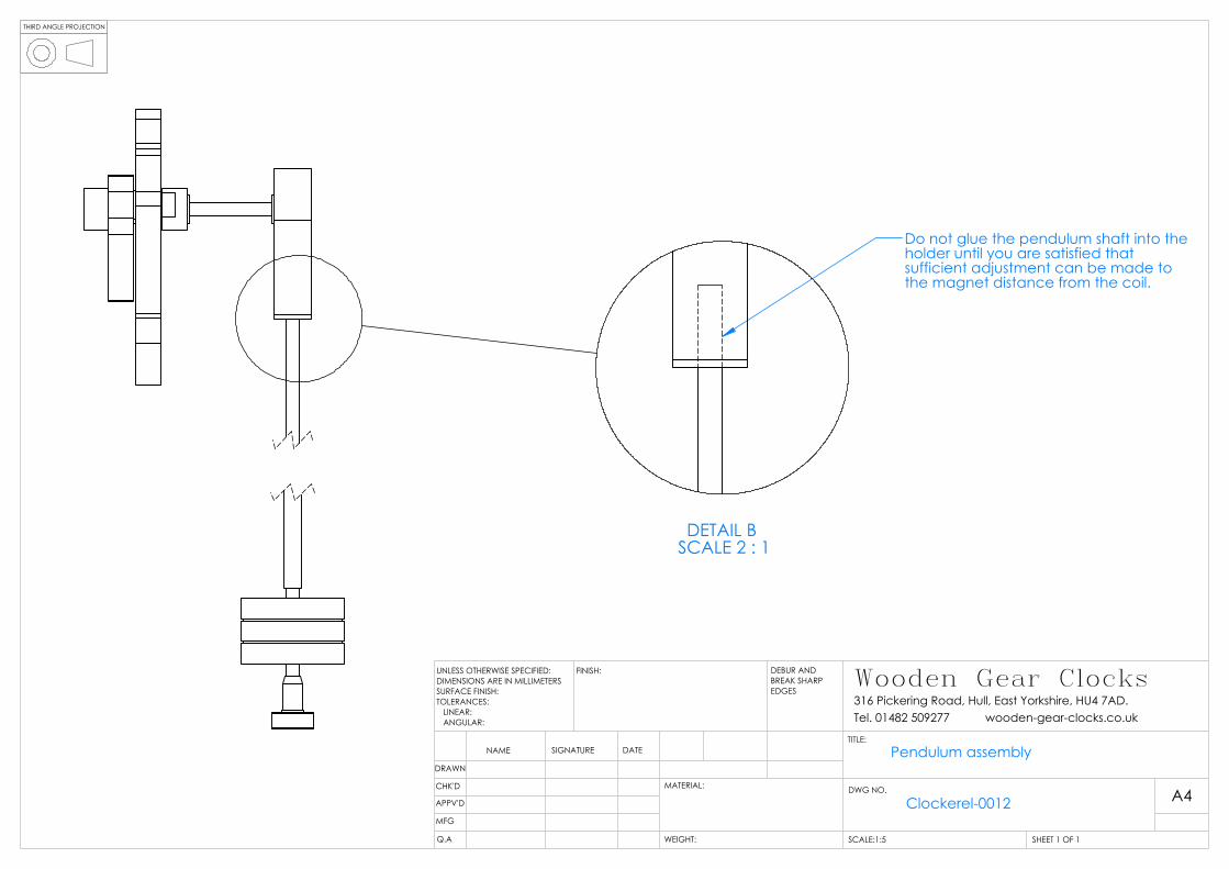
DETAIL B SCALE 2 : 1
Do not glue the pendulum shaft into the holder until you are satisfied that sufficient adjustment can be made tothe magnet distance from the coil.
DRAWN
CHK'D
APPV'D
MFG
Q.A
UNLESS OTHERWISE SPECIFIED:DIMENSIONS ARE IN MILLIMETERSSURFACE FINISH:TOLERANCES: LINEAR: ANGULAR:
FINISH: DEBUR AND BREAK SHARP EDGES
NAME SIGNATURE DATE
MATERIAL:
TITLE:
DWG NO.
SCALE:1:5 SHEET 1 OF 1
A4
WEIGHT:
Wooden Gear Clocks316 Pickering Road, Hull, East Yorkshire, HU4 7AD.Tel. 01482 509277 wooden-gear-clocks.co.uk
Pendulum assembly
Clockerel-0012

THIRD ANGLE PROJECTION
2
2
1
Triangles denote that this part is glued to shaft and the adjacent part.Pentagon denotes that this part is glued to adjacent part only so that the sub assembly can be removed.Circles denote an interferance or loose fit.
ITEM NO. PART NUMBER DESCRIPTION QTY.1 Face 12 Dowels 58mm long x 9 wooden dowel 2
DRAWN
CHK'D
APPV'D
MFG
Q.A
UNLESS OTHERWISE SPECIFIED:DIMENSIONS ARE IN MILLIMETERSSURFACE FINISH:TOLERANCES: LINEAR: ANGULAR:
FINISH: DEBUR AND BREAK SHARP EDGES
NAME SIGNATURE DATE
MATERIAL:
TITLE:
DWG NO.
SCALE:1:5 SHEET 1 OF 1
A4
WEIGHT:
Wooden Gear Clocks316 Pickering Road, Hull, East Yorkshire, HU4 7AD.Tel. 01482 509277 wooden-gear-clocks.co.uk
Face assembly
Clockerel-0013

THIRD ANGLE PROJECTION
1
2
3
4
3
6 7
8
1 2
4
5
6
ITEM NO. PART NUMBER DESCRIPTION QTY.
1 Ratchet wheel assembly DwgClockerel-0006 1
2 60 tooth wheel assembly Dwg Clockerel-0008 1
3 64 tooth wheel assembly Dwg Clockerel-0011 1
4 30 tooth wheel assembly Dwg Clockerel-0009 1
5 Hour hand assembly Dwg Clockerel-0010 1
6 Pendulum assembly Dwg Clockerel-0012 1
7 Frame assembly Dwg Clockerel-0002 1
8 Face assembly Dwg Clockerel-0013 1
DRAWN
CHK'D
APPV'D
MFG
Q.A
UNLESS OTHERWISE SPECIFIED:DIMENSIONS ARE IN MILLIMETERSSURFACE FINISH:TOLERANCES: LINEAR: ANGULAR:
FINISH: DEBUR AND BREAK SHARP EDGES
NAME SIGNATURE DATE
MATERIAL:
TITLE:
DWG NO.
SCALE:1:10 SHEET 1 OF 1
A4
WEIGHT:
Wooden Gear Clocks316 Pickering Road, Hull, East Yorkshire, HU4 7AD.Tel. 01482 509277 wooden-gear-clocks.co.uk
Clockerel assembly exploded
Clockerel-0014

THIRD ANGLE PROJECTION
3.0 approx
DRAWN
CHK'D
APPV'D
MFG
Q.A
UNLESS OTHERWISE SPECIFIED:DIMENSIONS ARE IN MILLIMETERSSURFACE FINISH:TOLERANCES: LINEAR: ANGULAR:
FINISH: DEBUR AND BREAK SHARP EDGES
NAME SIGNATURE DATE
MATERIAL:
TITLE:
DWG NO.
SCALE:1:5 SHEET 1 OF 2
A4
WEIGHT:
Wooden Gear Clocks316 Pickering Road, Hull, East Yorkshire, HU4 7AD.Tel. 01482 509277 wooden-gear-clocks.co.uk
Clockerel assembly
Clockerel-0015

Parts
List
ITEM NO. PART NUMBER DESCRIPTION QTY.1 Ratchet wheel shaft 3 brass rod x 49mm long 12 8 tooth wheel 33 6mm thk spacer 3mm
hole 134 ratchet wheel 15 M3 washer 166 6mm thk spacer 3mm
hole blind 37 60 toth wheel shaft 3 brass rod x 68mm long 18 60 tooth wheel 19 64 tooth wheel shaft 3 brass rod x 107mm long 110 64 tooth wheel 111 10 tooth wheel 112 Minute hand 113 30 tooth wheel shaft 3 brass rod x 45mm long 114 30 tooth wheel 115 Cannon tube 4 brass tube x 48mm long 116 Hour hand 117 6mm thk spacer 4mm
hole 518 32 tooth wheel 119 Pendulum shaft 3 brass rod x 54mm long 120 drive pawl lever 121 drive pawl 122 non return pawl 123 Pendulum mount 124 Bearing 623zz 1125 Pawl pin 2 brass rod x 16mm long 126 Pawl pin retainer 127 Pendulum bob weight
shaft 1
28 Pendulum shaft transition piece 4 brass tube x 30mm long 1
29 Magnet 130 Bob weight 131 frame 132 base bottom 133 base top 134 Battery holder 135 Coil 136 Simplified circuit
board 137 Switch 138 LED 139 Base Cover 140 Screw 3.5 x 20 441 Self adhesive felt pad 442 Brass M3 threaded
rod M3 brass rod x 45mm long 143 M3 Rivet nut 144 Face 145 Dowels 246 heat shrink 1

THIRD ANGLE PROJECTION
150
150
19
Drill 3 holes squarely through the board near the centre. 2mm, 3mm and 4mm diameter.These holes must be square to the board and allow the tube/rod to fit snugly. Board dimensionsare approximate.
DRAWN
CHK'D
APPV'D
MFG
Q.A
UNLESS OTHERWISE SPECIFIED:DIMENSIONS ARE IN MILLIMETERSSURFACE FINISH:TOLERANCES: LINEAR: ANGULAR:
FINISH: DEBUR AND BREAK SHARP EDGES
NAME SIGNATURE DATE
MATERIAL:
TITLE:
DWG NO.
SCALE:1:2 SHEET 1 OF 1
A4
WEIGHT:
Wooden Gear Clocks316 Pickering Road, Hull, East Yorkshire, HU4 7AD.Tel. 01482 509277 wooden-gear-clocks.co.uk
Gear wheel assembly jig
Clockerel-0016Plywood or MDF

THIRD ANGLE PROJECTION
90°
Jig ensures thatgear wheels are squareto the shaft.
DRAWN
CHK'D
APPV'D
MFG
Q.A
UNLESS OTHERWISE SPECIFIED:DIMENSIONS ARE IN MILLIMETERSSURFACE FINISH:TOLERANCES: LINEAR: ANGULAR:
FINISH: DEBUR AND BREAK SHARP EDGES
NAME SIGNATURE DATE
MATERIAL:
TITLE:
DWG NO.
SCALE:1:2 SHEET 1 OF 1
A4
WEIGHT:
Wooden Gear Clocks316 Pickering Road, Hull, East Yorkshire, HU4 7AD.Tel. 01482 509277 wooden-gear-clocks.co.uk
Clockerel-0017
Assembly jig with 60 tooth wheel

THIRD ANGLE PROJECTION
DETAIL B SCALE 1 : 1
Non return pawl and drive pawl should be set as shown with pendulumat rest. There should be 8 ratchet teethvisible. The drive pawl should beapproximately half way on one tooth.
DRAWN
CHK'D
APPV'D
MFG
Q.A
UNLESS OTHERWISE SPECIFIED:DIMENSIONS ARE IN MILLIMETERSSURFACE FINISH:TOLERANCES: LINEAR: ANGULAR:
FINISH: DEBUR AND BREAK SHARP EDGES
NAME SIGNATURE DATE
MATERIAL:
TITLE:
DWG NO.
SCALE:1:5 SHEET 1 OF 1
A4
WEIGHT:
Wooden Gear Clocks316 Pickering Road, Hull, East Yorkshire, HU4 7AD.Tel. 01482 509277 wooden-gear-clocks.co.uk
Ratchet setup detail
Clockerel-0018