wood shaper - c.searspartsdirect.com · stability of machine the shaper must be bolted securely to...
TRANSCRIPT

MODEL NO.113.239201
SHAPER ONLY
113.239390SHAPER WiTH STEEL
LEGS AND MOTOR
SerialNumber
Model and serial
number may be foundon the front of
the table.
You should record both
model and serial number
in a safe place forfuture use.
CAUTaON:Read GENERAL
and ADDITIONAL
SAFETY
iNSTRUCTIONS
carefully
WOOD SHAPER
• assembly
e operating
o repair parts
Sold by SEARS, ROEBUCK AND CO., Chicago, IL. 60684 U.S.A.
Part No. 72036 Printed in USA.

....... _L,_l_J̧̧ .... I....... rr'l ......... - -II ..... i ¸ I li •
general safety
10.
11.
instructions
12.
1. KNOW YOUR POWER TOOLRead and understand the owner's manual and labels
affixed to the tool. Learn its application andlimitations as wetl as the specific potential hazardspeculiar to this tool,
2. GROUND ALL TOOLSThis tool is equipped with an approved 3-conductorcord and a 3-prong grounding type plug to fit theproper grounding type receptacle. The green conductorm the cord is the grounding wire. Never connect thegreen wire to a live terminal,
3. KEEP GUARDS IN PLACEin working order, and in proper adjustment andalignment.
4. REMOVE ADJUSTING KEYSAND WRENCHES
Form habit of checking to see that keys and adjustingwrenches are removed from toot before turning tt on.
5. KEEP WORK AREA CLEANCluttered areas and benches invite accidents. Floor
must not be slippery due to wax or sawdust.
6, AVOID DANGEROUS ENVIRONMENTDon't use power tools in damp or wet locations or
expose them to rain. Keep work area well lighted,Provide adequate sui'rOunding work space.
7. KEEP CHILDREN AWAYAll vtsltors should be kept a safe distance from workarea.
8. MAKE WORKSHOP KID-PROOFwith padlocks, master switches, or by removing
starter keys.
9. DON'T FORCE TOOLtt wttl do the job better and safer at the rate for which_t was designed.
USE RIGHT TOOLDon't force tool or attachment to do a job it was not
designed for.
WEAR PROPER APPARE LDo not wear loose clothing, gloves, neckties or iewefry(rings, wrist watches) to get caught in moving parts.Nonslip footwear is recommended, Wear protectivehair covering to contain long hair, Roll long sleevesabove the elbow,
USE SAFETY GOGGLES (Head Protection)
Wear Safety goggles (must comply with ANSI Z87:1)at all times, Everyday eyeglasses only have impactresistant lenses, they are NOT safety glasses. Also, useface or dust mask if cutting operation iSdustY, and ear
for power tools
protectors (plugs or muffs) during extended periods ofoperation,
13. SECURE WORKUse clamps or a vise to hold work when practical. It'ssafer than using your hand, frees both hands to operatetool,
14. DON'T OVERREACHKeep proper footing and batance at all times_
15. MAINTAIN TOOLS WITH CAREKeep tools sharp and clean for best and safestperformance_ Follow instructions for lubricating and
changi ng accessories.
16. DISCONNECT TOOLSbefore servicing; when changing accessories such asblades, bits, cutters, etc.
t7. AVOID ACCIDENTAL STARTINGMake sure switch is in "OFF" position before pluggingIn,
18. USE RECOMMENDED ACCESSORIESConsult the owner's manual for recommended
accessones Follow the {nstructions that accompanythe accessories. The use of improper accessories maycause hazards,
19. NEVER STAND ON TOOLSerious injury could occur if the tool is tipped or if the
cutting tool is accidentaJly contacted,
Do no_ store materials above or near the tool such that
_I is necessary to stand on the tool to reach them.
20. CHECK DAMAGED PARTSBefore further use of the tool, aguard or other part thatis damaged should be carefu!ly checked to ensure that it
will operate proper(y and perform its intended function.
Check for alignment of moving parts, binding of mowng
parts, breakage of parts, mounting, and any otherconditions that may .affect its operation. A guard or
other part that _s damaged should be properly repaired
or replaced.
21. DIRECTION OF FEEDFeed work into a blade or cutter against the directionof rotation of the blade or cutter only,
22. NEVER LEAVE TOOL RUNNINGUNATTENDED
: Turn power off. Don't leave tool until it comes to acomplete stop.

ADDiTiONAL SAFETY iNSTRUCTIONSFOR WOOD SHAPER
CAUTION: Turn motor switch "OFF" and disconnect 19, NEVER perform freehand shaping - Use either the
Power Cord when changing Shaper cutters or makingadju st ments.
Safety is a combination of operator common sense andalertness at all times when the Wood Shaper is being used,
WARNING: FOR YOUR OWN SAFETY, DO NOTATTEMPT TO OPERATE YOUR WOOD SHAPER UNTILIT IS COMPLETLY ASSEMBLED AND INSTALLEDACCORDING TO THE INSTRUCTIONS... AND UNTILYOU HAVE READ AND UNDERSTAND THE
FOLLOWl NG: PAGE
1. General Safety Instructions for Power Tools ..... 22. Getting to Know your Wood Shaper ............ 123. Basic Wood Shaper Operation ................. 154. Maintenance .............................. 19
5. Stability of Machine
The Shaper must be bolted securely to a stand or workbench, in addition, if there is any tendency for theShaper to tip over or move during certain operations, itshould be bolted to the floor.
6. Location
The Shaper should be positioned so neither theoperator nor a casual observer is forced to stand in linewith the workpiece when straight line shaping. ThisShaper is intended for indoor use only.
7. Protection: Eyes, Hands, Face, Ears, Body
Wear safety goggles that comply with ANSI Z87.11968. Wear ear plugs or muffs during extended periodsof operation. Do not wear gloves ... roll long sleevesabove the elbow.
8. Afways feed against rotation of the cutter. NEVER"back up" the workpiece.
9. Do not take deep cuts or feed the stock too rapidly.
10. Be particularly careful in shaping wood that containscross grains or knots, as these may cause the hands tobe thrown into the cutter or cause kickbacks.
11. Before applying power, make sure the keyed washer isinstalled immediately under the spindle nut and thespindle nut is securely fastened, and all guards are in theproper position. Make sure cutters are sharp.
12. Avoid awkward hand positions, where a sudden slipcould cause a hand to move into the cutter. Never reachin back of or around the cutter with either hand to hold
down the workpiece.
13. Accumulations of stock or of finished work should notbe allowed on the table. Never clear table while cutter is
rotating.
14. Rubbish, shavings, stock, or other objects or materialshould not be allowed on the floor where they may be atripping hazard.
15. Use working forms, patterns or holders whereverpossible, and keep them maintained. Care should betaken that the work is securely fastened in thesefixtures. Stock is often of such size or shape that itmust be clamped in a holder before being shaped, Theinside jaws which clamp directly against the stockshould be lined with sand paper. Guards may also bemounted on a holder to afford additional protection.
t6. When the fence is used, make sure it is securely fastenedand will not slip, and is properly adjusted.
t7. Do not wear gloves, neckties, loose sleeves, or ragged ortorn clothing of any kind. Wear safety gogglescomplying with ANSI Z87.1-1968 to protect your eyesfrom dust or flying particles.
18. DO NOT perform layout, assembly, or set-up work on
the table while the cutting toot is rotating.
fence, or a starting pin in the table and a collar on thespindle, or a pattern.
20. Do not place your fingers or hands near edge ofmaterial being cut.
21. NEVER perform irregular shaping operations with thecutter guard removed. Be positive it is installed andadjusted per instructions.
22. NEVER perform internal shaping operations on thisShaper.
23. Do not use your hands to remove objects or materialsfrom around cutters; use a brush.
24. Do not tamper with guards nor make them inoperativein any way.
25. ALWAYS joint or plane edge on surface of workpiecethat will be in contact with fence and/or table.
26. NEVER attempt to shape warped or twisted or bowedwork pieces.
27. Before leaving the machine, make sure the motor switchis "OFF" the power cord is disconnected from the
power source, and the cutter has stopped revofving.
28. Never operate the Shaper without a protective cover onthe unused shaft end of a double ended motor.
29. If any part of this Shaper should break, bend, or fai! in
any way or any electrical component fail to performproperly, or if any is missing, shut off power switch,remove power supply cord from power supply andreplace damaged missing and/or failed parts beforeresuming operation.
WARNING: DO NOT ALLOW FAMILIARITY (GAINEDFROM FREQUENT USE OF YOUR WOOD SHAPER) TOBECOME COMMONPLACE. ALWAYS REMEMBERTHAT A CARELESS FRACTION OF A SECOND ISSUFFICIENT TO INFLICT SEVERE INJURY.
30. Note and follow Safety Instructions that appears on theShaper fence.
WAR NING
A KEYED WASHER MUST ALWAYS
BE USED UNDER THE SPINDLE NU'i"
31. Note and follow Safety instructions that appear on theShaper Switch assembly,
DANGERFOR YOUR OWN SAFETY:
READ *&_D UNDE{_TANb OWNE_4 S
M_tNUAL BEFORE OPERATING _,_AC_4_NE
_ WEAR SAFE_'P¢ GOGGLES pen ANSI Z87 1AT ALL TIM_S
2 BE POSIT_V_ K]_Y_D W_.$HER 1_ DIRECTLYUND_.R SF'INDLE ,NUT AND SP_NDL_ _VLiT lS
T_G_TB_FORE TU_I_G S_A_E_ ON
3 ALWAYS _EED VVORKPI_CE AGAIN$1ROTA:tON O_ CUT/,_ MOTOR ._t_D
CU'FTER ROTATE _N SAME _)t_CT_DN
4 AVOID AW?;WARD NAND POS_T_D_4$
5 K_P F;N_RS AWAY' I:ROM _VOLVtNG
CUTTER ,-- USE F_XTUR_S W_4E_NECESSARY
_5 USE OV_R_4_AD GUARD WHEN AOJUS'€.ABLE €_NC_ _$ NOT IN PLA_E
WARNING: THE 4-318" FLAT MOTOR PULLEY AND THE2" SPINDLE PULLEY FURNISHED, WILL RUN THE CUT -TER APPROXIMATELY 9000 R.P.M. WH EN USED WITH A3450 MOTOR. NEVER SUBSTITUTE THESE PULLEYSTO INCREASE THIS SPEED BECAUSE IT COULD BEDANGEROUS.
Note and follow safety instructions that appear on themotor.
CAUTION: Reversible motor - check rotationbefore using,

ii 'can: 'reSult: in foreignwhich::can result in
before cornmencingSears
E LECTRICA L:IREQU! R EIV!ENTSCONNECTING TO POWER SOURCE OUTLET
This machine must be grounded while in use to protect theoperator from efectr:ic shock.
Plug power cord into a 120V properly grounded type outletprotected by a t5 amp dual element time delay or circuit
saver fuse or circuit breaker. If you are not sure that youroutlet is properly grounded, have it checked by a qualifiedelectrician.
WARNING: DO NOT PERMIT FINGERS TO TOUCHTHE TERMINALS OF PLUGS WHEN INSTALLING ORREMOVING THE PLUG TO OR FROM THE OUTLET,
WARNING: IF NOT PROPERLY GROUNDED THISPOWER TOOL CAN INCUR THE POTENTIAL HAZARDOF ELECTRICAL SHOCK. PARTICULARLY WHENUSED IN :DAMP LOCATIONS |N PROXIMITY TOPLUMBING. IF A:N ELECTRICAL SHOCK OCCURSTHERE IS THE POTENTIAL OF A SECONDARYHAZARD SUCH AS YOUR HANDS CONTACTING THECUTTER BLADE.
If power cord is worn or cut, or damaged in any way, have itreplaced immediately.
Yourshaper is wired for 120 volts and h_s a plug th at looks likethe one shown below.
3-PRONG
PLUG
GROU NDINGPRONG
PROPERLY
GROUNDEDOUTLET
@
If the outlet you are planning to use for this power tool is
of the two prong type DO NOT REMOVE OR ALTERTHE GROUNDING PRONG IN ANY MANNER. Use an
adapter as shown and always connect the grounding lug toknown ground.
tt is recommended that you have a qualified electrician
replace the TWO prong outlet with a properly groundedTHREE prong outlet.
A temporary adapter as shown below is available forconnecting plugs to 2=prong receptacles. The greengrounding tug extending from the adaptor must beconnected to a permanent ground such as to a properlygrounded outlet box.
A temporary adapter as illustrated is available forconnecting plugs to 2-prong receptacles, The temporaryadapter should be used only until a properly groundedoutlet can be installed by a qualified electrician.
GROUNDING LUG
l_his power tool is equipped with a 3_conductor cord andgrounding type plug listed by Underwriters" Laboratories. Theground conductor has a green jacket and is attached to thetool housingat one end and tothe ground prong in the attach-ment plug at the other end.
This plug requires a mating 3-conductor grounded type outletas shown above.
3-PRONG
PLUG
MAKE SURE THISIS
KNOWN GROUND
2*PRONG
RECEPTACLE
ADAPTE R
NOTE: The adapter illustrated is for use only if you alreadyhave a properly grounded 2-prong receptacle.
The use of any extension cord will cause some loss ofpower, To keep this to a minimum and to preventoverheating and motor burn-out, use the table below todetermine the minimum wire size (A.W.G,) extension cord.Use only 3 wire extension cords which have 3-pronggrounding type plugs and 3-pote receptacles which acceptthe tools plug.
Extension Cord Length Wire Size AWG
0-25 FT ................................. 1626-50 FT ............................... 1451-100 FT ................................ 12
MOTOR ROTATION
The motor is designed to rotate either clockwise orcounterclockwise and can be changed from one rotation tothe other bythe use of a select switch located on the side ofthe motor.
4

UNPACKING AND CH
CONTENTSWARRANTY .... : ................................ 2General Safety Instruction for Power Tools .......... 2
Additional Safety Instructions for Wood Shaper ...... 3Motor Specifications and Electrical Requirements .... 4UNPACKING AND CHECKING CONTENTS ....... 5
List of Loose Parts .............................. 5ASSEMBLY ...................................... 6
Tools Needed ................................... 6
Installing Elevating Rod and Table Support ........ 7Mounting Belt Guard and Motor to Motor Mount .. 7Installing Motor Pulley ........................... 8
Mounting Motor Support Assembly to Shaper ..... 9Mounting Switch Assembly ...................... 9Assembling Steel Legs .......................... 9Mounting Wood Shaper on Floor Stared .......... 10Plugging in Motor .............................. 10
Installing Shaper Fence -- For Straight EdgeShaping only ................................. 11
installing Shaper Cutter Guard --- For Curvedor Irregular Shaping only ..................... 11
GETTING TO KNOW YOUR: WOOD SHAPER .... 12On-Off Switch ................................. 12Elevating Control Lever ......................... 13Spindle Lock Knob ............................. !3Spindle ........................................ t3Spacers ....................................... t 3Keyed Washer ................................. 13Fence Adjusting Knob .......................... 13Fence Lock Knob ............................... t3Fence Faces ................................... t3Cutter Guard ................................... 13
Starting Pin .................................... 13Removing and Installing Cutter .................. 13
ADJUSTMENTS ................................ 14
Shaper Fence .................................. !4Fence Faces ................................... 14
BASIC SHAPING OPERATIONS ................. 15
Use of Cutter Spacers .......................... t5Straight Edge Shaping .......................... 16Shaping With Use of Miter Gauge and
Hold-Down Clamp (Optional Accessory) ........ 16Irregular or curved Shaping ..................... 17
MAINTENANCE ................................. 19LUBRICATION .................................. 19
Motor Maintenance and Lubrication ............. t9RECOMMENDED ACCESSORIES ............... 19TROUBLE SHOOTING ........................... 20REPAIR PARTS ................................. 22
Motor Connections ............................. 27
O
ECKING CO NTENTSModel 113.239390 Wood Shaper is shipped complete inone carton and includes st:eel legs and motor.
Model 113.239201 Wood Shaper is shipped complete inone carton but DOES NOT INCLUDE Steel Legs or Motor.
Separate al! parts from p_oking materials and check eachone with the illustration and the tist of Loose Parts to makecertain all items are accounted for, before discarding any
packing material.If any parts are missing, do not attempt to assemble theShaper, plug in the pov_er cord or turn the switch on untilthe missing parts are obtair_ed and are installed correctly.
Remove the protective oil that is applied to the table top
and edges of the t_ble. Use any ordinary household typegrease and spot remover.CAUTION: Never use g,asoline, naptha or similar highlyvolatile solvents.
Apply a coat of automobilJe wax to the table.
Wipe aH parts thoroughly with a clean, dry cloth,
WARNING: FOR yOUR OWN SAFETY, NEVERCONNECT PLUG TO POWER SOURCE OUTLET UNTILALL ASSEMBLY STEPS ARE COMPLETE, AND YOUHAVE READ AND UNDERSTAND THE SAFETY ANDOPERATIONAL INSTR UCT_ONS.
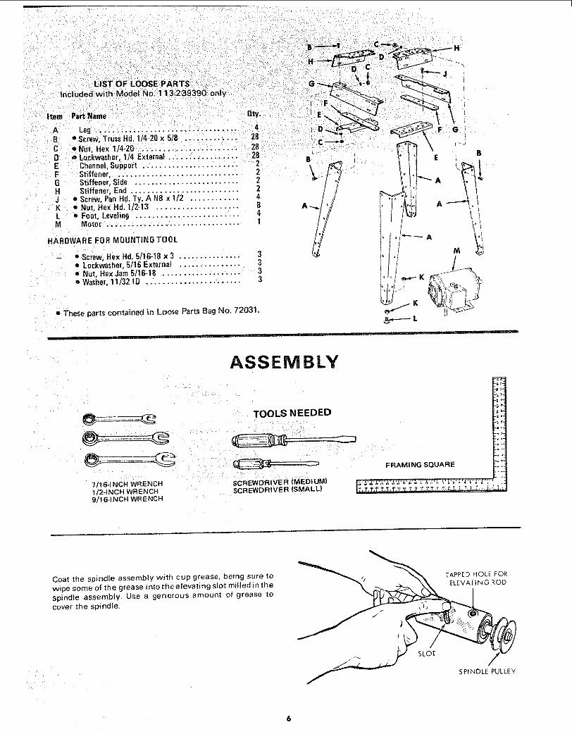
LIST OF LOOSE PARTS
Included with Model No. 113.23920t and 113,239390
Item Part Name Qt_/.
ABCDEFGHJKLMNOPQR
ST
Motor Mount .............................
Guard, Pulley ............................. tPulley, Motor ............................. 1Belt, "V" 1/2 x 33: ........................... 1
Support A_sembfy, _H ..................... 1Support Assembly, L.H ...................... 1Guard, Cutter ............................. tHub Assembly, Lock ....................... tNut, Lock ............................... 1Stud Nut .................................. 1Support, Guard ............................ 1Bracket, Support ........................... IFence Assembly ............................ 1Plate, Guard ................................ ISwitch Box Assembly ...................... 1Spin_fe Assembly .......................... 1Base
Owners Manual............................ I
Bag Assembly, Loose Parts (Part No. 72022)Containing The Fo_llowing:Starting Pin 1Insert, Table
............................ I
Wre rich 1Screw, Hex Hd. 3/8-16; x 1 2
=====================2Bolt, Carriage 5/t6-18 × t-1/4 .............. 4Washer 21164 i.D. x 71B O.D. x 1/8 .......... 4Screw, W/L0ckv_asher 5716-18 x 3/4 ......... 3Washer 11/32 I.D. x 1 - !/16 x 1,/8 ............ 2Wrench, Hex "L °' 5132
...... * ............. 1
Wrench, Hex *'L'" I/4Knob
3Nut, He× 5/16-t8L0ckwasher, Int. 5I:t _;................ 7Han_er, Cable - ..................... 3
Screw0 Hex H_1."5"1:I_: lj'_ 1"2 .............. 1Elevating Rod ................ 2
tnclude.i ¸¸ . H • : ;.:
Item PartName
A LegBCDEFGHJKLM
0_.
• S++e+,"ii&+_+.+;+i+++++'_+;+: i:i:i:i; ::ii ++eNut, Hex 1]4-20 ._+++ ..... ....:.;: ........ 2B -o L0ckwasher, 114 External ................... 2B
Channel,Support ....................... 2Stiffener .............................. 2Stiffener, Side .......................... 2Stiffener; End .......................... 2
• Screw, Pan lid. Ty. A N8 x 1/2 ............ 4• Nut, FlexHd. t/2-13 .................... B• Foot, Leveling ......................... 4
Motor ................................ 1
liARDWARE FOR MOUNTING TOOL
" Screw,liex lid. 5/16-18 x 3 ............... 3• Lockwasher,5116External ............... 3• Nut, Hex Jam 5/16-1B ................... 3• Washer,ti/32 ID ....................... 3
• These parts contained in Loose Parts Bag No, 72031.
, i,," _ ..
B
':' " H
+ s
"; [
1
f N
ASSEMBLY
7tI6++NCH WRENCH
1/2-INCH WRENCH9116-1NCH WRENCH
Coat the spindle assembly with cup grease, being sure towipe some of the grease into tf+e elevating stot miffed in thespindle assembJy, Use a generous amount of grease tocover the spindle.
- i ¸
?
SLOT
TAPPED HOLE FOR
ELEVATING ROD
SPINDLE PULLEY

INSTALLING ELEVATING ROD
AND TABLE SUPPORT
Position table upside down on 2 x 4's on edge for supportand clearance for Spindle assembly.
1. Install (3/8-24) jam nut on short threaded end ofelevating rod and screw the rod into the threads in theside of spindle assembly.
2. Remove spindle lock knob. Insert the spindle assemblyinto the table support, position the long angle of theelevating rod straight down and tighten jam nutsecurely. The angle portion of elevating rod must beparallel with spindle assembly.
3. Install knob on end of elevating rod.
4. Rotate the set screw into the table support, whilemoving the elevating rod back and forth, until the dogpoint on end of set screw enters the elevating slot inspindie assembly. This can be felt as the set screw andspindle assembly are rotated. Tighten the set screw,then back it off 1/4 turn. This will allow enoughclearance for the spindle assembly slot to slide ondog-point end of set screw.
5. Check operation of spindle several times, by movingelevating control lever back and forth in order to makesure it is not binding, yet slides effectively on thedog-point end of screw. Readjust set screw slightly, ifrequired, for smooth operation.
Reinstall spindle lock knob.
, Position shaper base on table support casting so thethree mounting holes are aligned. Install and tighten thethree 5/!6-18 × 3/4-inch hex-head screws with lockwashers.
MOUNTING BELT GUARD AND MOTOR
TO MOTOR MOUNT
1. Place the motor mount on your workbench.
2. Support rear of motor mount with 3/4" stock asshown.
3. Find four 5/16" x 18 x 1-1/4 carriage bolts, four5/16-18 hex nuts, and two 21/64 x 3/4 x t/16 FlatWashers. Position hardware as shown.
POSITION MOTOR WITH51"8 IN. DIA, SHAFT TI41S END
BELT GUARD
MOTOR MOUNT
3/4 IN, STOOl<
t/16 IN.THiCKWASHERS
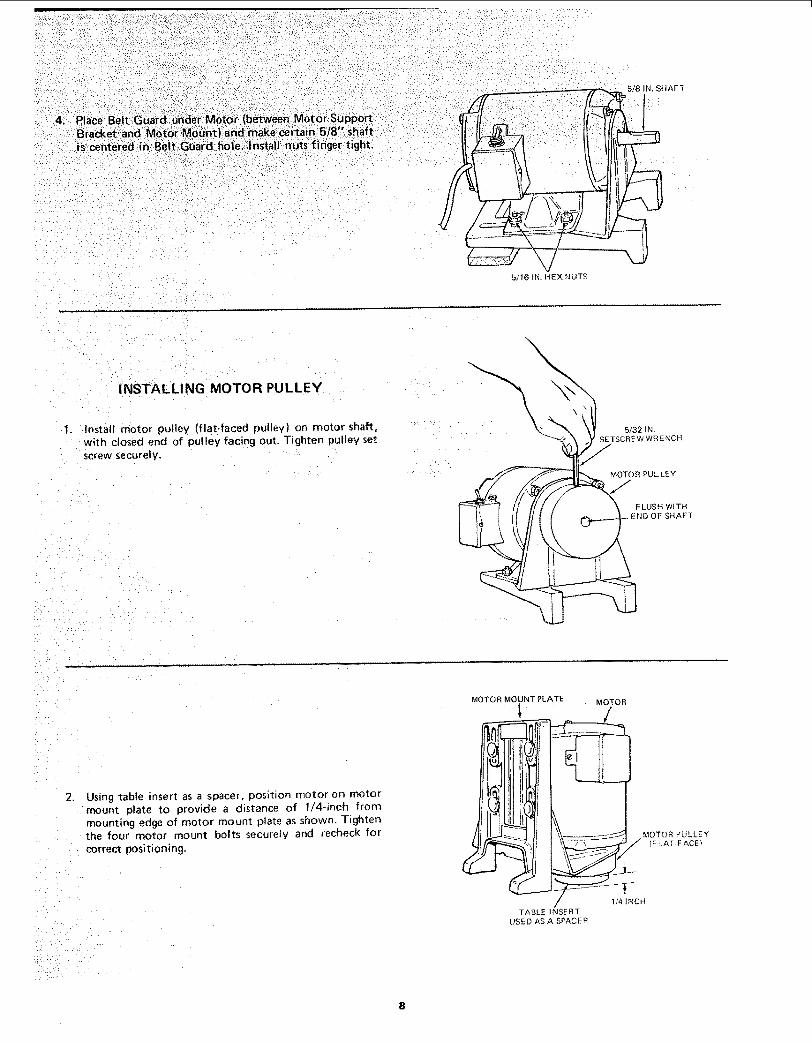
5/16INHEXNUTS
INSTALLING MOTOR PULLEY
1. Install motor pulley (flat-faced pulley) on motor shaft,with closed end of pulley facing out. Tighten pulley setscrew securel y.
5132 IN,
SETSCREW WRENCHf
/"
MOTOR PUL LEY
F LUSH W{THSHAFT
2. Using table insert as a spacer, position motor on motormount plate to provide a distance of 1/4-inch frommounting edge of motor mount plate as shown. Tightenthe four motor mount bolts securely and recheck forcorrect positioning.
_IOTOR MOiNT PLATE MOTOR
MOTOR £ULLEY
/ 1/4 INCH
TABLE INSE RTUSED AS A SPACER

MOUNTING MOTOR SUPPORT ASSEMBLY
TO SHAPER
1. Place V-belt on motor pulley and attach motor mountplate to shaper base with two bolts (3/8-16 x 1-inch)and washers. Leave bolts finger tight.
2. Roll the belt onto spindle pulley, pull motor mountplate toward end of base until belt is tight enough toprevent slipping and tighten the two bolts. Each boltshould be in approximately the same position in thebase slots.
3o Position elevating rod in approximate mid position andturn spindle pulley by hand several times to see that thebelt rides in the approximate mid position of motorpulley. If not, recheck assembly. The belt shouldchange positions on motor pulley as the lever position ischanged (while the spindle pulley is rotated by hand).
ELEVATINGROD
MOTOR MOUNT PLATE
SPINDLE BASEPULLEY
MOTO R
1.
2.
3,
MOUNTING SWITCH ASSEMBLY
Attach the switch assembly to the underside of the
Shaper table using the two screws and Iockwasherspacked with the switch.
ASSEMBLING STEEL LEGS
(Supplied with 113,239390 only)
Assemble the two (2) End Stiffeners and the two (2)Side Stiffeners using four (4) 1/4_20 Truss head screws.The End Stiffeners are placed on top of each SideStiffener as shown. Insert screws through the 9/32 inchdiameter holes and finger tighten 1/4-20 nuts.
Attach the four (4) legs to the side and End Stiffenerusing 1/4-20 screws, _ockwashers and nuts as shown.
Remove the four (4) Truss head screws which wereassembled in Paragraph No. One. Place the two (2)Support Channels as shown, in position, align holes insupports with holes in the side Stiffeners, replacetockwashers and nuts. Tighten all nuts using 7/16"wrench,
4. The two (2) Stiffeners, (F) are fastened to the top sideof each side stiffener using N8 x t/2 self-threading
screws. The guard plate is mounted as shown using samescrews.
5. Install leveling feet as shown. To ieve! Leg Set, ]oosennut on inside of leg and turn nut on outside to raise orlower feet. Adjust a_l four levelers, if necessary, and then
tighten nuts on inside of leg.
NOTE: These levelers are not intended for height
adjustment.
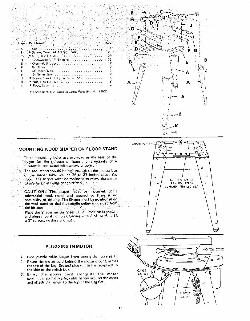
Part NameItem Qty,
A Leg .... .......... _ 4B e Screw, TrussHd. l/4_20xS]8 .,. ..... .,... 28C • Nut. Hex 1/4_20 , .. ..................... 28D Lockwasher, _/4 E xternat ................ 28E Channel. Support ........................ 2F Stiffener ............................... 2G Stiffener, Side ........................ 2H Stiffener, End .......................... 2j o Screw, Pan Hd•Ty. A N8 × t/2 ............ 4K o Nut. Hex Hd. 1/2-13 .................... 8L • Foot, Leveling ......................... 4
• These parts contained in Loose Parts Bag No. 72031•
IL
GUARD PLAT_
SHAPER ONMOUNT,NGWOOD FLOORSTAND
_' t, Three mounting holes are provided in the base of the:shaper for the purpose of moundng it securely on a
substantial tool stand with screws or bolts,
2. The t0ol:stand should be high enough so the top surfaceof the:shaper table wilt be '35 to 37 inches: above the
floor. The Shaper must be mounted to allovy the motorto overhang:_ear edge Of tooi stand, :
CAUTIONi The on aSubstantial toot:: stand andi: secured so:ithere: is _ no
: possibility of tlpping;The Shaper:must be positioned onthe tool stand so that the spindle pulley is guarded from :
: : ' the bottom: ::i' :" i:/:::::i' 'i: :::: "......................
PIace the Shaper On: the Steel LEGS. Position as shown,and align mounting h01es_ Secure with 3 e& 5/16"x 18x 3" screws; washers and nuts.
NO, 8 x 1/2 IN.PAN HD. SCREW
(SUPPLIED WITH LEG SET)
PLUGGING IN MOTOR
1, Find plastic cable hanger from among the loose parts.
2, Route the motor cord behind the motor mount, across
the top of the Leg Set and plug it into the receptacle inthe side of the switch box.
3. Bring the power cord alongside the motorcord.., wrap the plastic cable hanger around the cords
and attach the hanger to the top of the Leg Set.
CABLE
HANGER
CORD
MOTOR CORD
lO
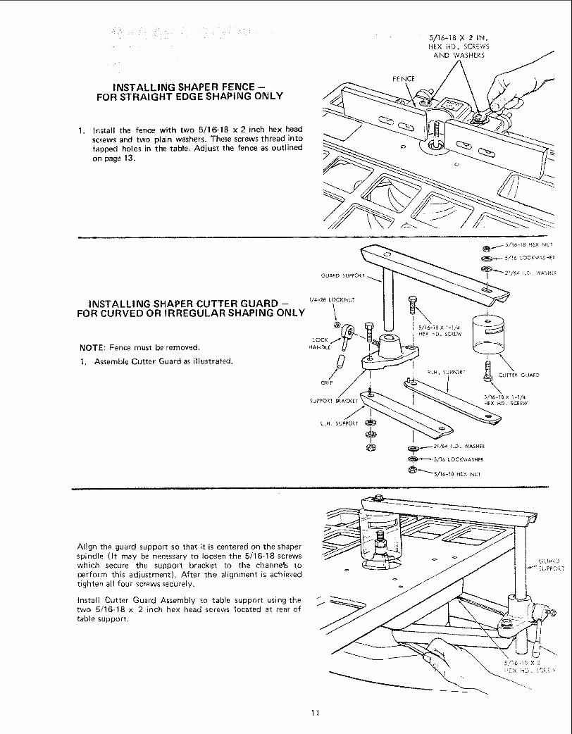
INSTALLING SHAPER FENCE --FOR STRAIGHT EDGE SHAPING ONLY
Install the fence with two 5/16-18 x 2 inch hex headscrews and two plain washers. These screws thread intotapped holes in the table, Adjust the fence as outlinedon page 13.
FENCE
5/16-18 X 2 IN,HEX HD. SCREWS
AND WASHERS
GUARD SUPPORT
INSTALL! NG SHAPER CUTTER GUARD -FOR CURVED OR IRREGULAR SHAPING ONLY
NOTE: Fence must be removed.
1. Assemble Cutter Guard as illustrated.
]/4-28 LOCI(NUT
L.H, SUPPORT
t
Align the guard support so that it is centered on the shaperspindle (it may be necessary to loosen the 5/t6-18 screwswhich secure the support bracket to the channels toperform this adjustment). After the alignment is achievedtighten all four screws securely.
install Cutter Guard Assembly to table support using thetwo 5/t6-18 × 2 inch hex head screws located at rear of
table support,
11
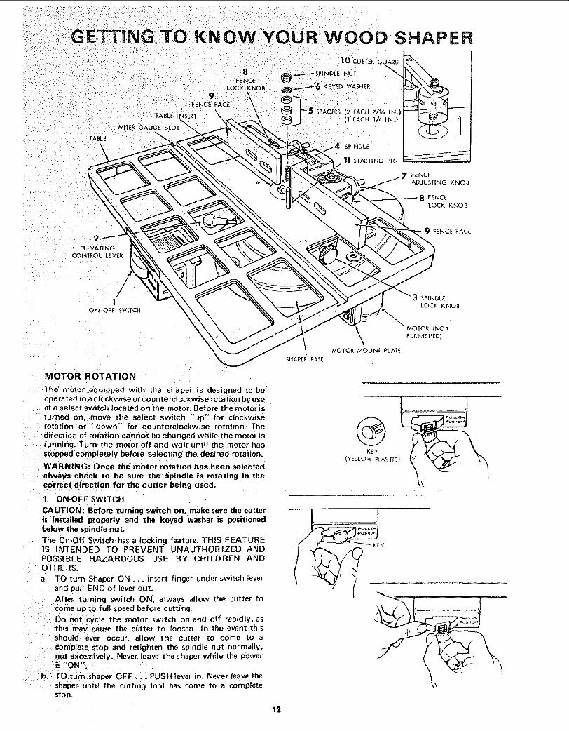
SHAPER
TABLE
ELEVATING ]
CONTROL LEVER
1ON-OFF SWITCH
9 ¸FENCE FACE
10 cwrTE_GUARD
8 _ SP|NDLE NUT "_"_.FENCELOCK KNOB _:6 KEYED WASHER
J_ 5 SPACERS [2 EACH 7/'t6 IN,)
!__ _X'/4 SPINDLE
_"-"_ 11 STArTiNG PIN
7 FENCE_) ADJUSIING KNOB
SPINDLE
LOCK KNOB
\ MOTOR (NOTFURNISHED)
MOTOR MOUNT PLATE
SHAPER BASE
MOTOR ROTATION
The motor equipped with, the shaper is designed to beoperated in a clockwise or counterclockwise r0tation by useof a select switch tocated on the motor. Before the motor is
turned on, move the select switch "up" for clockwiserotation or "'down" for counterclockwise rotation. Thedirection of rotation cannot be changed while the motor isrunning. Turn the motor off and wait until the motor hasstopped completely before selecting the desired rotation:
WARNING! Once the motor rotation has been selected
always check to be sure the spindle i_s rotating in thecorrect direction for the cutter being used.
1. ON-OFF SWITCH
CAUTION: Before turning switch on, make sure the cutteris installed properly and the keyed washer is positionedbelow the spindle nut.
The On-Off Swi,tch has a locking feature. THIS FEATUREIS INTENDED TO PREVENT UNAUTHORIZED ANDPOSSIBLE HAZARDOUS USE BY CHILDREN ANDOTHERS.
a. TO turn Shaper ON... insert finger under switch leverand pull END of lever out.
After turning switch ON, always allow the cutter tocome Up to full speed before cutting.
Do not cycle the motor switch on and off rapidly, asthis may cause the cutter to loosen. In the event thisshould ever occur, allow the cutter to come to acomplete stop and retighten the spindle nut normally,not excessively. Never leave the shaper while the poweris "'ON,:
b. TO turn Shaper OFF... PUSH lever in. Never leave theshaper until the cutting tool has come to a completestop.
@KEY
(YELLOW _LAST]C}
KEY
12

c. TO lockswitchin OFFposition..,holdswitchINwithonehand.,. REMOVE key with other hand,ALWAYS LOCK THE SWITCH "OFF" WHENSHAPER IS NOT IN USE... REMOVE KEY ANDKEEP IT IN A SAFE PLACE,,. ALSO... tN THEEVENT OF A POWER FAILURE (ALL OF YOURLIGHTS GO OUT) TURN SWITCH OFF .,, LOCK ITAND REMOVE THE KEY. THIS WILL PREVENTTHE SHAPER FROM STARTING UP AGAIN WHENTHE POWER COMES BACK ON,
2, ELEVATING CONTROL LEVER
The Elevating Control Lever moves the spindlevertically a distance of 7/8-inch to locate the cutter atthe desired vertical position.
3. SPINDLE LOCK KNOB - used to lock the spindle andquill assembly after the desired height has beendetermined.
CAUTION: Always release the quill lock knob beforeattempting to change the position of spindle andtighten the knob securely before starting operation.
4. SPINDLE - This shaper is designed for use withmaximum 2-1/2-inch diameter cutters having a 1/2-inchdiameter bore.
5. SPACERS - A total of three spacers are provided, two7/16 inch thick and one 1/4 inch think for positioningthe cutter for desired shapes.
6. KEYED WASHER - Must always be positionedimmediately below the spindle nut.
7. FENCE ADJUSTING KNOB - Each fence face may be
moved forward or backward by turning the fenceadjusting knobs.
8. FENCE LOCK KNOB - After the desired fence face
position has been selected, the fence is secured bytightening the fence lock knobs.
9. FENCE FACES - Each fence may be moved forwardor backward by releasing the fence lock knob andturning the fence adjusting knobs. Each fence faceoperates independently of the other, by means of theadjusting mechanism. After the desired fence positionhas been selected, it is secured by tightening the fencelock knob. The fence faces wilt close in from a
maximum three-inch opening down to one-inch forsmall diameter cutters, by loosening the two screws inthe front of each face and sliding the face to the desiredposiiton. The screws must be tightened securely aftereach setting.
CAUTION: The opening between inner ends of fence facesshould never be larger than required to just clear theparticular cutter being used. ALWAYS ROTATE THESPINDLE BY HAND BEFORE STARTING THE SHAPERMOTOR TO MAKE SURE CUTTER DOES NOT STRIKEFENCE FACES.
10. CUTTER GUARD
NOTE: Used for curved or irregular shaping only-fence must be removed and starting pin must be inplace on in-feed side.
11.
12.
Provides added protection for irregular shaping. Guardis adjustable for various thickness of material.
CAUTION: Always rotate the spindle by hand beforestarting the shaper motor to make sure cutter does notstrike guard.
STARTING PIN
The Starting Pin must be used as a pivot to support thework until it has been fed into the cutter and againstthe collar. The Starting Pin may be located in either ofthe two threaded holes near the table insert opening,
depending upon the direction of rotation, butALWAYS on the in-feed side.
REMOVING AND INSTALLING CUTTERS
a. Raise spindle to maximum height
b. To REMOVE cutter, hold spindle with the t/4" hexwrench and loosen nut with wrench provided asshown -- Reverse procedure to TIGHTEN SPINDLENUT.
NOTE: TO AVOID POSSIBLE BENDING OF THESPINDLE LOOSEN OR TIGHTEN NUT WITH BOTHWRENCHES POINTING AS NEARLY tN THE SAMEDIRECTION AS POSSIBLE.
CAUTION: Always have the keyed washer directlyunder the nut, otherwise the nut may loosen and
serious injury could result.
1/'4 IN, HEX WRENCH
\
LOOSE N
/
t/
TI GHTE N
WRONG
R_GHT ,!,,
13

ADJUSTMENTS
WARNING: FOR YOUR OWN SAFETY, TURN SWITCH"OFF" AND REMOVE PLUG FROM POWER SOURCEOUTLET BEFORE MAKING ANY ADJUSTMENTS.
ADJUSTABLE SHAPER FENCE
I, Move both fence faces out 3/4" by turning the twofence adjusting knobs.
2.
.
Position fence faces in the same plane by using aframing square or straightedge and adjusting the fenceadjusting knob.
Loosen the fence attaching bolts and shift the completefence assembly until both fence faces are the samedistance from the miter slot,
Tighten fence attaching bolts after fence has been
correctly positioned.Check this adjustment after:' tightening bolts to makesure it did not change, : : ;
Lock all controls securely after: :desired settings haveI_een completed ....
:i
:STRAIGHT EDGEFENCE FACE
FENCE FACES
t. Loosen the four (4) screws as shown and slide eachfence face in as close to the cutter as possible, but donot permit the cutter to strike fence faces.
2. Set the fence faces so the cutter (Not supplied seeRecommended Accessory List) projects far enoughbeyond them to produce the desired depth of cut, Ifthe cutter is set to remove only a portion of the edge ofthe work piece, the two fence faces should be set evenwith each other.
!4
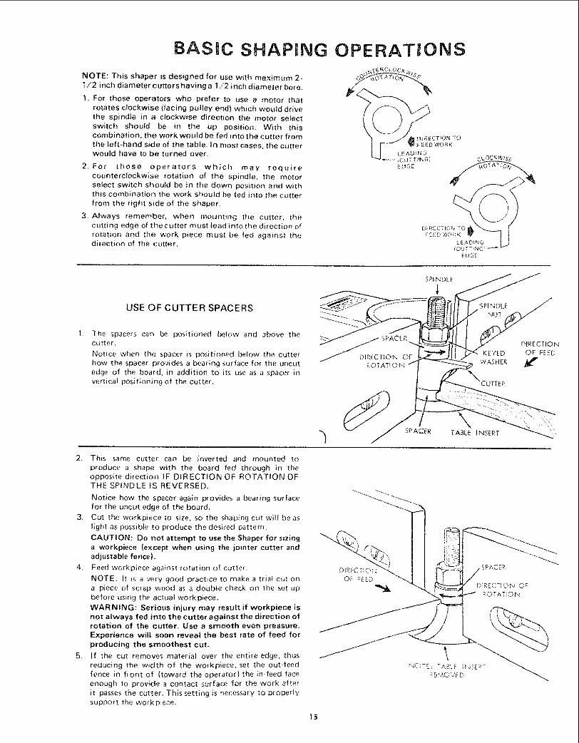
BASIC SHAPING
NOTE: This shaper is designed for use with maximum 2-t/2 inch diameter cutters having a 1/2 inch diameter bore.
1. For those operators who prefer to use a motor that
rotates clockwise (facing pulley end) which would drivethe spindle in a clockwise direction the motor selectswitch should be in the up position. With thiscombination, the work would be fed into the cutter fromthe left-hand side of the table. In most cases, the cutterwould have to be turned over.
2. For those operators which may requirecounterclockwise rotation of the spindle, the motorselect switch should be in the down position and withthis combination the work should be fed into the cutterfrom the right side of the shaper.
3. Always remember, wllen mounting the cutter, thecutting edge of the cutter must lead into the direction ofrotation and the work piece must be fed against thedirection of the cutter
OPERATmONS
USE OF CUTTER SPACERS
SPINDLE
The spacers can be positioned below and above thecutter.
Notice when the spacer is positioned below the cutterhow the spacer provides a bearing surface for the uncutedge of the board, in addition to its use as a spacer invertica! positioning of the cutter,
_ SPACER DIRECTION
TtON OF KEYED OF FEEDROTATION WASHER
_"NCUTTER
2. This same cutter can be inverted and mounted to
produce a shape with the board fed through in theopposite direction IF DIRECTION OF ROTATION OFTHE SPINDLE tS REVERSED.
Notice how the spacer again provides a bearing surfacefor the uncut edge of the board,
3. Cut the workpiece to size, so the shaping cut will be aslight as possible to produce the desired pattern.
CAUTION: Do not attempt to use the Shaper for sizinga workpiece {except when using the jointer cutter andadjustable fence).
4. Feed workpiece against rotation of cutter.
NOTE: It is a very good practice to make a trial cut ona piece of scrap wood as a doubte check on the set-upbefore using the actual workpiece.
WAR NING: Serious injury may result if workpiece isnot always fed into the cutter against the direction ofrotation of the cutter, Use a smooth even pressure.Experience will soon reveal the best rate of feed forproducing the smoothest cut,
5. If the cut removes material over the entire edge, thusreducing the width of the workpiece, set the out-feedfence in front of (toward the operator) the m-feed faceenough to provide a contact surface for the work after
it passes the cutter, This setting is necessary to properlysupport the workpiece.
15
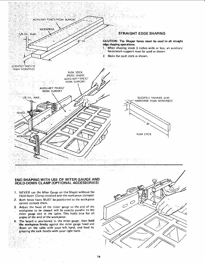
A'JX
WC_KPIECE
27 IN;
STRAIGHT EDGE SHAPING
CAUTION: The Shaper fence must be used in all straightedge shaping operations.I; When shaping stock 3 inches wide or _ess, an auxiliary
fence/work Support must be used as shown.
2. Make the push stick as shown.
SLIGHTLY:THICK'ER
THAN WORKPlECE
PUSH STICK
(FEEDS UNDER
AUXILIARY FENCE/
WORK SUPPORT
AUXILIARY FENCE/ \
WORK SUPPORT
SLIGHTLY THINNER AND
NARROWER THAN WORKPIECE
FENCEN
2O
WORKPIECEPUSH STICK
END SHAPING WITH USE OF MITER GAUGE ANDHOLD-DOWN CLAMP (OPTIONAL ACCESSORIES)
1. NEVER use the Miter Gauge on the Shaper without theHold-down Clamp installed and the workpiece clamped,
2, Both fence faces MUST be positioned so the workpiececannot contact them.
3, Adjust the head of the miter gauge so the end of theworkpiece to be shaped wil! be exactly parallel to themiter gauge slot in the table, This holds true for all
angles of the end of the workpiece,
4. The board is positioned in the miter gauge; then hold:::the w0rkpiece firmly against the miter gauge head and:doWn on the table with your left hand, and feed by::gripping the lock handle with your right hand.
/:i::::::i::i/5 ;:::i:i:ii<. :;, ¸:¸7:¸ i ¸ •
t6

IRREGULAR OR CURVED SHAPING
A variety of shapes may be produced with the shaper bychanging the the height of cutter in relation to theworkpiece, by using various combinations of cutters onsuccessive passes, and/or by inverting cutter and changingdirection of spindle rotation and feed direction. The tableinsert must be removed if the cutter does not clear the holein the insert when the cutter is lowered below the table
surface: check clearance before turning switch "ON":
1. To make irregular shaping cuts remove power cablefrom electrical source, remove the fence assembly,select the shaper collar that will position the cutter toobtain the desired pattern, and lock the shaper collarand cutter on the spindle,
NOTE: A shaper collar may be located above or belowa cutter, or between the two cutters selected.
[ ( ° SPINDLE NUT
"ljj wAs,,R\ .OF "° _ -,, ...,.__SPACER _. I
SHAPER COLLAR(OPTIONAL ACCESSORY)
O
OSHAPER COLLAR SET
(OPTIONAL ACCESSORY)
2. Mount the cutter guard and adjust as shown.
Position the Guard verticatlV (A) (Guard should justclear workpiece)
Center the Guard over the cutter. (B)
NOTE: Rotate cutter by hand and check for properclearance inside guard.
f
STARTING J
17
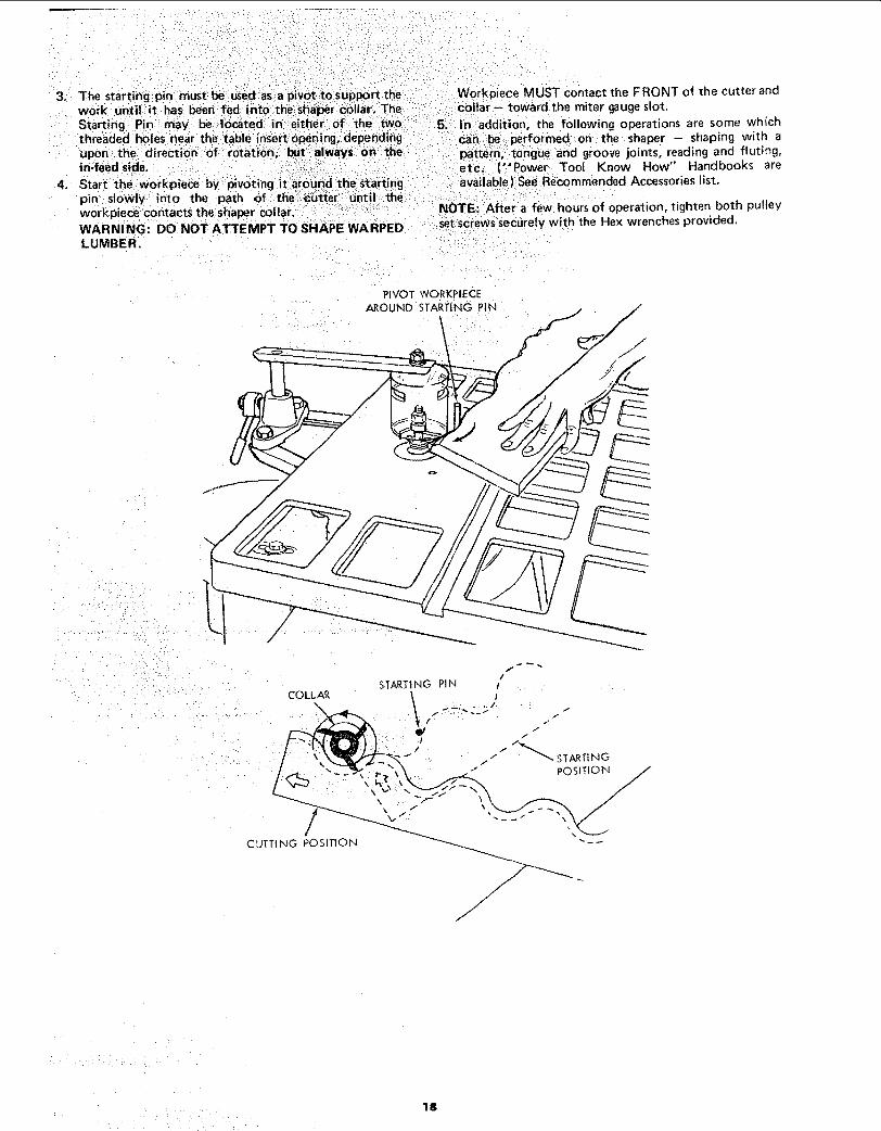
3. The starting pin must beused asa pivot to support thework untillit has been :fed intothe :s_a_r col ari:TlieStarting:Pin may the:i:tw6
threaded holes "ear:the' table insert:oPening;: dependingupon i the: direction 0f :r0tatloni:: buti_aiways 0_ :thein-feed side; ' : ' :_:l_
4,
WARNING: DO NOT ATTEMPT TO SHAPE WARPEDLUMBER.
Workpiece MUST contact the FRONT of the cutter andcollar L_ toward the miter gauge slot.
5_ In addition, the following operations are some whichperformed::or_: the shaper - shaping with a
pattern, l,t0ngue and groove joints, reading and fluting,etc:. (" Power Tool Know How" Handbooks areavailable ).See Recommended Accessories st.
NOTE:I After a few hours of operation, tighten both pulleyt screws securely with the Hex wrenches provided.
PIVOT WORKP|£CE
AROUND STARTING PIN
18

MAINTENANCEWARNING: FOR YOUR OWN SAFETY, TURN SWITCH"OFF" AND REMOVE PLUG FROM POWER SOURCEOUTLET BEFORE MAINTAINING OR LUBRICATINGYOUR SAW.
NOTE: After a few hours of operation, tighten both pulleyset screwssecurely with the Hex wrenches provided.
Frequently clean your cutting tools with Craftsman Gumand Pitch Remover.
A coat of automobile-type wax applied to the table wilthelp to keep the surface clean and allow workpieces to slidemore freely,
if the power cord is worn or cut, or damaged in any way,have it replaced immediately.
LUBRICATION
The ball bearings used on the cutter spindie have beenpacked with lubricant at the factory and require no furtherattention,
To maintain smooth and easy operation, occasionally add a
few drops of oil to the outside of the spindle assembly,
MOTOR MAINTENANCE AND LUBRICATION
1. The sleeve bearings, in both end shields of the motor,have been lubricated at the factory with correctlubricant. No. other part of the motor requireslubrication.
2. Re-lubricate motor bearings in accordance with theinstructions on the nameplate. Be sure to wipe off dirt orgrit if present around oil hole caps to prevent anypossibility of foreign material contaminating the oilwicks that supply the bearings with oil Use a good gradeof medium weight minera_ oil, such as automobileengine oil, SAE 20.
3. If disassembly of the motor is necessary, it should bereturned to your nearest Sears retail or mail-order storein order to prevent voiding the guarantee.
4.
NOTE: The speed of this motor cannot be regulated orchanged.
Every effort should be made to prevent foreign materialfrom entering the motor. When operated underconditions likely to permit accumulations of dust, dirt orwaste within the motor, a visual inspection should bemade at frequent intervals. Accumulations of dry dustcan usually be blown out successfully.
NOTE: Motors used on wood-working tools areparticularly susceptible to the accumulation of sawdustand wood chips and should be blown out or "vacuumed"frequently to prevent interference with normalventilation and proper operation of the centrifugally-operated starting switch.
SEARS RECOMMENDS THE FOLLOWING ACCESSORIESITEM CAT. NO. ITEM CAT. NO.
Floor Base ................................. 9-22213Steel Legs .................................. 9-22236Casters ............................ 9-22222, 9-22221Shaper Collar Set ........................... 9-23672Shaper Cutters ......................... See CatalogPush Blocks ................................. 9-2299
Miter Gauge ............................. 9-29929Miter Gauge Hold Down .................... 9-29928"Power Tool Know How" handbooks
Table Saw .............................. 9-2918Radial Saw .............................. 9_2917
Universal Jig .............................. 9-323 t
Sears may recommend uther Accessories not i'_stedin manual.
See your nearest Sears Store or Catalog Department for otherAccessories,
Do not use any Accessory unless you have received and readcomplete instructions for its use,
19
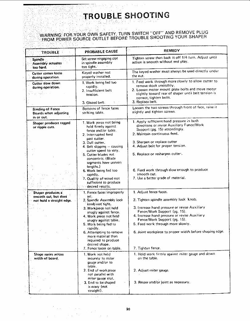
TROUBLE SHOOTING
WARNING_ FOR IYOUR OWN SAFETY, TURN SWITCH "OFF" AND REMOVE PLUGFROM POWER SOURCE OUTLET BEFORE TROUBLE SHOOTING YOUR SHAPER
"_-17 : _TROUBLE
:itoo hard.
Cutter comes loose
:: during operation.
Cutter slow down
during operation,
J PROBABLE CAUSE
Set screw engaging slot
in spindle assemblytoo tight,
Keyed washer notproperly installed.
I 1. Work being fed toorapidly.
2. Insufficient belttension.
3, Glazed belt
Bottoms of fence facesstriking table.
....Bindi. 0fF "0e...... iBoards when adjustingIN or out.
Shaper produces ragged 1, Work piece not beingor riplMe cuts. held firmly against
fence and/or table.
_. 2. Interrupted feed
: past cutter.3. Dull cutter.
, 4, Belt slipping - causing, cutter speed to vary.5, Cutter blades not
concentric. (Blade
segments have unevenlengths.)
, : F: 6. Work being fed too
7_ Quality of wood not. : sufficient to produce
: : : ' ::: .... desired results,
smooth cut, but does
., not l'_|d a straight edge,
Shape varies across.width of board.
REMEDY
Tighten screw then back it off 1/4 turn. Adjust untilaction is smooth without end play.
The keyed washer must always be used directly underthe nut.
t. Feed work thro'ugh more slowly to allow cutter to
remove stock smoothly,2, Loosen motor mount plate bolts and move motor
slightly toward rear of shaper until belt tension iscorrect, tighten bolts.
3. Replace belt,
screwsLoosen the two through front of face, raise its_ightly and tighten screws,
set.: 2: Spindie Assembly lock
knobnot tight. '3. WOrkpiece not held
snugly against fence.4. Work piece not held
snugly against table.5, Work being fed to
rapidly.
6. Attempting to removemore material thanrequired to producedesired shape.
7. Fence loose on table.
1. Work not heldsecurely to mitergauge and/or totable.
2. End of workpiecenot Paraltel withmiter gauQe slot.
3, End to be shaped Iis wavy (notstraight),
1, Apply sufficient hand pressure in bothdirections or revise Auxiliary Fence/WorkSupport (pg. 15) accordingly.
2. Maintain continuous feed,
3. Sharpen or replace cutter4. Adjust [belt for proper tension.
5. Replace or resharpen cutter,
6. Feed work through slow enough to producesmooth cut,
7. Use a better grade of material.
fence faces.
2. Tighten spindle assembly lock knob.
3, increase hand pressure or revise AuxiliaryFence/Work Support (10g, 15).
4. Increase hand pressure or revise AuxiliaryFence/Work Support (pg. t 5),
5. Feed work through more slowly,
6, Joint workpiece to proper width before shaping edge.
7, Tighten fence.
1. Hold work firmly against miter gauge and downon the table,
2. Adjust miter gauge.
3. Resaw andlor joint as necessary.
2O

TROUBLE SHOOTING -- MOTOR
NOTE: Motors used on wood-working tools are particularly susceptible to the accumulationof sawdust and wood chips and should be blown out or "vacuumed" frequently to preventinterference with normal motor ventilation.
TROUBLE....... ,,,,_ ...................
Excessive noise.
Motor fails to develop 1full power. NOTE:LOW VOLTAGE: (Poweroutput of motordecreases rapidty with 2decrease m voltage atmotor terminals For
exampte, a reduction of 3,10% in voltage causesa reduction of 19% mmaximum power outputof which the motor Is
capabIe, and a reductionof 20% in voltage causesa reduction of 36% mmaximum power output.)
............ i,, , , ,,
Motor starts slowly 1,or fails to come upto full speed, 2
3,
Motor overheats. 12,
1.Starting switch inmotor will not
operate.
2.3.
,,_ , ...... , ,,
Motor stalls 1(resufting in blownfuses or tripped 2circuit breakers),
3.
, ........ ® ,....
Frequent opening of !.fuses or circuit 2.breakers.
PROBABLE CAUSE
1. Motor.
Circuit overloaded withtights, appliances andother motors
Undersize wires or c_rcuit
too long.
General over}oadmg ofpower companyfacilities.
Low voitage wiU nottrip relay
Wir_dings burned out
or opera.
Start{ng relay not
ope, fat*r;g .................
Motor overloaded
Improper cooftng. (Aircirculation restricted
through motor due tosawdust, accumulatinginside of saw).
Bu rned "sw"i"tCh contacts
(due to extendedhold-in periods causedby [ow line voitage, etc.)
Shorted capacitorLoose or brokenconnecttons
Starting switch notoperating.
Voltage too low to permitmotor tO reach operatingspeed.Fuses or circuit breakersdo not have sufficient
capac,ty.
Motor overloaded.
Fuses or c_rcuit breakersdo not have sufficient
capacity
Starting swdch notoperating (motor doesnot reach speed}
REMEDY
t. Have motor checked by qualified servicetechniciar_. Repair service _s available atyour nearest Sears store.
t. Do not use other appliances or motors onsame circuit when using U"te saw
2. increase wire sizes, or reduce !er_gth of w_r}ngSee "Motor Specifications arqd Etectrtca!Requirements" sechon
3. Request a voltage check from the powercompany
I Request vottage check from the power company
2 Have motor repaired or replaced
3 Have relay rep{aced
1 Feed work slower into blade.
2. C_ean out sawdust to provide normal aircirculation through motor.See "Maintenance and Lubrication" section.
'i'["Havd switch reP'i'acedan'd req"uesi'a'"v'o_tagecheckfrom the power company.
2 Have capacitor tested and replace _f defechve3. Have wiring checked and repaired
1 Have switch replaced
2 Request voltage check from the power company
3. install proper s_ze fuses or c_rcuit breakers
1 Feed work slower into btade
2. ]nstatl proper s_ze fuses or c_rcu_t breakers
3 Have sw_tch replaced
21
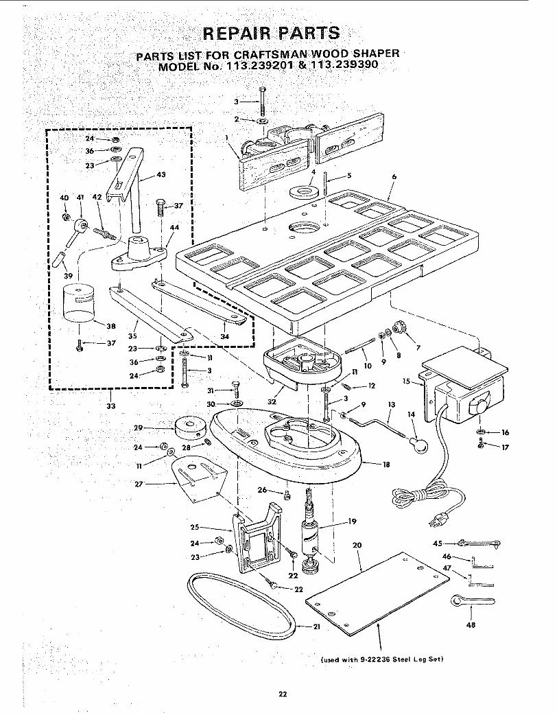
R:::EPAl R::iPART S
I\\
6
22

PARTS LIST FOR CRAFTSMAN WOOD SHAPERMODEL No. 113.239201 & 113.239390
Always Order by Part No. - Not by Key Number
FIGURE 1
"°YiNo.
123456789
101112131415161718192O21222324
2526
PartNo.
7200860167STD 5231203941139613C3929039512STD 551037STD 54113739629STD55103138799396283854660382STD 551210STD 51 t 10539215
72014STD 304330STD 53311 2STD 551031STD 54123139217453068
Description
Fence Assembly (See Figure 2)Washer, .343 x 1.062 x 1/8
*Screw, Hex Hd. 5/16-18 x 2tnsert, TablePin, Table DowelTable (includes Nameplate)Knob, Lock
*Washer, 13/32 x 47/64 x 1/t6*Nut, Hex. Jam, 3/8-24
Stud, Lock*Washer, 2t/64 x 7/8 x t/8
Screw, Set, 3/8-24 x 3/4 Dog Pt.Rod, ElevatingKnobSwitch Box Assembly (See Figure 4)
*Lockwasher, Internal No. 10*Screw, Pan Hd. 10-32 x t/2
Base
Spindle Assembly (See Figure 5)Plate, Guard
_Belt, V, 1/2 x 33
*Bolt, Carriage 5/16-18 x 1-1/4*Washer 21/64
*Nut, Hex 5/1618Mount, MotorScrew, Mach, 5/16-18 x 3/4,
Hex, Hd. wiLockwasher
Key
j No.[ 27
28
29303t32333435363738394041
42434445464748
' tPart iNo. Description
L......... '
72003 Guard, PulleySTD 503102 i * Screw, Set 5/t6-18 x 5/!6,
Soc. Hd. Cup Pt.39230 Puiiey, Motor, (w/Set Screw)STD 55t037 i'Washer, 25/64 ×!-9/64 x 7/64
STD 523710i*Screw, Hex Hd. 3/8-16 x 139216720277202472025STD 55t 23!STD 523t 127200560262STD 54152570001
5663472026720236803637435378373871372022
172036
i Support Tablei Guard, Asm. Cutteri Support Assembly, R.H.I Support Assembly, L.H.* Lockwas=her, tnternal 5/16
Screw, Hex Hd. 5/16 x 18x 1-1/4Guard, CutterGrip
*Nut, Lock t/4-28Hub Asm. Lock
Includes Key No. 39)Stud, NutArm, GuardHolder, Guard
Hanger, Cabtel'Wrench, Hex., t/4t Wrench, Hex., 5,32
Wrench
Bag Asm. Loose Parts(not illustrated)
i Owners Manuat (not illustrated)
*Standard Hardware Items - May be Purchased Locaily.
23

PARTS LIST FOR CRAFTSMAN WOOD SHAPERMODEL No. 113;239201 & 113.239390
! 2 1 6
7
/ i11 IO
9
\
11 t0
FIGURE 2 - FENCE ASSEMBLY 72008
2••••••i•3¸
•: _•4 • ••
_"i_'__i 6 "/
_ _9
t01112
Parti.: Description
, L
72008 : Fence Assembly CompleteSTD 511t005 *Screw, Pan Hd., t0-24 x 1/238711 " Bracket, Retaining386!2 Knob, Adjusting
: 18451 Washer; Spring38413. Frame38531 Knob
i 38 i10 Shoe Assy., Fence
38533 Plate, Work Face (Right)STD 512507 *Screw, Pan Hd., 1/4.20 x 3/4STD 551012 *Washer, Plain, 1/438532 Piate, Work Face (Left)
*Standard Hardware Item - May be Purchased Locally.
24
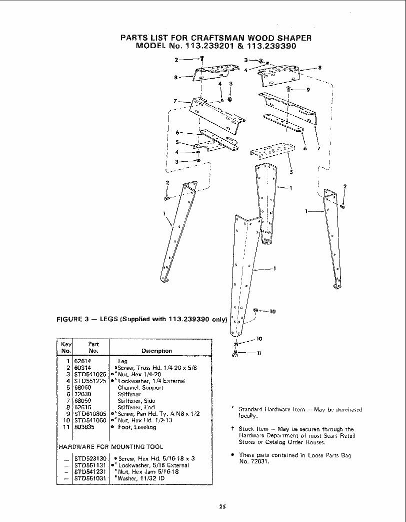
PARTS LiST FOR CRAFTSMAN WOOD SHAPERMODEL No. 113.239201 & 113.239390
2
FIGURE 3 -- LEGS (Supplied with 113.239390 only)
K 3yNo.
1234567
1011
PartNo.
6261460314STD541025STD55122568060720306805962615STD610805STD 541050803835
Description
LegoScrew, Truss Hd. I/4-20 x 5/8
e'Nut, Hex 1/4-20e* Lockwasher, 1/4 External
Channel, SupportStiffenerStiffener, SideStiffener, End
e'Screw, Pan Hal. Ty. A N8 x 1/2o'Nut, Hex Hd. 1/2-13e Foot, Leveling
HARDWARE FOR MOUNTING TOOL
w
STD523130STD551131STD541231STD551031
e Screw, Hex Hd. 5/!6-t8 x 3e* Lockwasher, 5/16 External
*NUt, Hex Jam 5/16-18*Washer, 11/32 ID
Standard Hardware Item - May be purchasedlocally.
Stock Item - May be secured through theHardware Department of most Sears RetailStores or Catalog Order Houses,
These parts contained in Loose Parts BagNo. 72031.
25
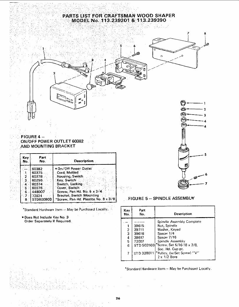
PARTS LIST FOR CRAFTSMAN WOOD SHAPER:_MODEL No. 1113,239201:& 113.239390
7 8
6
//
FIGURE 4 -ON/OFF POWER OUTLET 60382AND MOUNTING BRACKET
i Key PartNo, No.
• JL LLL
"i 60382
i 603752 60378
314
5
6 4480077 '; 72034
STD600803
Descriptioni , ii
o 0n/Off Power Outlet
Cord, MoldedHousing; Switch .....
Screw; Pan Hd. No. 6 x 3/4
Bracket, Switch MoUntingi'Screw, Pan Hd: Plastite No, 8x 3/8
*Standard Hardware Item -- May be Purchased Locally.
• Does Not Include Key No. 3Order Separately If Required.
7
FIGURE 5- SPINDLE ASSEMBLY
Key PartNo. No. Description
...... rl i,
-- Spindle Assembly Complete1 396! 52 397113 396164 396175 720076 STD 503103
STD 328011
Nut, SpindleWasher, KeyedSpacer 1/4Spacer 7/16Spindle Assembly
*Screw, Set 5/16-18 x 3/8,
Soc. Hd. Cup pt.*Pultey, (w/Set Screw) "V'"
2x 1/2 Bore
/i:•_:••_/=•¸_!ii!̧• ••• • •
_/_ii//iiii_i_iiiiiiiiiii:i_!i_i_iii_!_iii!I i __i__III_i i_ _ i
*Standard Hardware Item - May be Purchased Locally.
26

1 2
PARTS LIST FOR CRAFTSMAN WOOD SHAPERMODEL No. 113.239201 & 113.239390
3
NOTE:
ANY ATTEMPT TO REPAIR THIS MOTORMAY CREATE A HAZARD UNLESSREPAIR IS DONE BY QUALIFIEDSERVICE TECHNICIAN,
REPAIR SERVICE IS AVAILABLEAT YOUR NEAREST SEARS STORE,
FIGURE 6 -- 72035 MOTOR PARTS LIST
KeyNo.
1
23
PartNo.
60306
6408864258
Description
Screw, 8-32 x 3/8, ThreadCutting, Stotted, SerratedHd.
Cover, TerminalCord with Plug
MOTOR CONNECTIONS
WARNING: FOR YOUR OWN SAFETY, NEVERCONNECT PLUG TO POWER SOURCE OUTLET UNTILALL ASSEMBLY STEPS ARE COMPLETED.
1. Open motor connector box cover tocated on ]eft end ofmotor (viewed from rear of saw) using a flat bladescrewdriver.
2. Remove GREEN SCREW and Iockwasher and insertscrew through round metal terminal on the end of theGREEN wire of power cord with Iockwasher betweenterminal and motor frame. (See illus.)
3. Reinsert GREEN SCREW in the threaded hole. Tightensecurely.
4. Insert terminal end of WHITE wire on spade terminalmarked T4 on the motor. Push terminal firmly untilseated.
5. Insert terminal end of BLACK wire on spade terminalmarked T1 on the motor. Push terminal firmly untilseated.
6. Close motor connector box being sure that power cord isseated in the largest strain relief groove, and tighten boxcover screws.
TERMINALGREEN
_NTERNAL\ "_ 1LOCKWASHER _'
BLACK WIRE TOTERMINAL T1
GREEN WIREGF_EEN SCREW
STRAIN RELIEFPVE
WIRE TOT4
27
SERVICE
MODEL NO.113.239201
SHAPER ONLY
113.239390SHAPER WITH STEEL
LEGS AND MOTOR
HOW TO ORDER
REPARR PARTS
WOOD SHAPER
Now [h_._[ you have purch_}sed your wood shaper, should a need
ever exist for repair parts or service, simply contact arW Sears
Service, Center m_d most Sears, Roebuck and Co, stores. Be sure
to provide aI! perti_ent facts when Vou call or visit,
]"he model number of your wood shaper will be found on a
ptate attached to your wood shaper on the front of the tab}e,
WHEN ORDERING REPAIR PARTS, ALWAYS GIVE THEFOLLOWtN3 INFORMATION:
PART NUMBER PART DESCRIPTION
MODEL NUMBER113.2392011! 3.239390
NAME OF ITEMWOOD SHAPER
A!I parts listed may be ordered from any Sears Service Centerand most S_ars stores, tf the parts you need are not stocked
locally, your order will be electronically transmitted to a Sears
Repair Parts Distributior_ Center for handling,
Sold by SEARS, ROEBUCK AND CO., Chicago, IlL. 60684 U.S.A.
Part No, 72036 FormNo, SP4926-2 Printed in U.S.A_ 6/89