wls27 pro multimode process data aoi guide 6/1/2021
TRANSCRIPT

WLS27 Pro Multimode Process Data AOI Guide 6/1/2021
This document covers the installation and use of an Add-On Instruction (AOI) for the Logix Designer software package from Rockwell Automation. This AOI handles cyclic IO-Link Process Data Out to a Banner WLS27 Pro Multimode device via an IO-Link Master connected to an Allen-Bradley PLC. The AOI covers parsing and display of the WLS27 Pro Multimode Process Data Out. The AOI has nine User Defined Tag data types.
Components Banner_WLS27_MM_PD.L5X Banner_WLS27_MM_CC_PD.L5X UDT Packaged with the AOI Banner_WLS27_MM_Adv_v2 Banner_WLS27_MM_CC Banner_WLS27_MM_Colors Banner_WLS27_MM_LC_CC Banner_WLS27_MM_Level Banner_WLS27_MM_PDIO Banner_WLS27_MM_PD_CC_v2 Banner_WLS27_MM_Run Banner_WLS27_MM_Segment Other AOIs Available Separately Banner has AOI files for controlling other Banner IO-Link devices and for a variety of IO-Link Masters. Banner also has AOI files for easily handling Banner device Parameter Data. Download the WLS IO-Link Files for these AOI files.

6/1/2021 WLS27 Multimode Pro Process Data AOI Guide
0
Contents 1. Installation Process .......................................................................................................................................................... 1
2. Configuring the IO-Link Master ...................................................................................................................................... 3
3. Configuring the AOI ........................................................................................................................................................ 4
4. Using the AOI .................................................................................................................................................................. 7
Appendix A IO-Link Master Cheat Sheet .................................................................................................................... 10

6/1/2021 WLS27 Multimode Pro Process Data AOI Guide
1
1. Installation Process This section describes how to install the AOI in Logix Designer software.
1. Open a project.
2. In the Controller Organizer window, right-click on the Add-On Instruction folder. Select the Import Add-On Instruction option.
3. Navigate to the correct file location and select the AOI to be installed. In this example the
“Banner_WLS27_MM_PD.L5X” file will be selected. Click the Open button.

6/1/2021 WLS27 Multimode Pro Process Data AOI Guide
2
4. The Import Configuration window will pop up. The default selection will create all the necessary items
for the AOI. Click the OK button to complete the import process.
5. The AOI is added to the Controller Organizer.
window and should look like the picture at left.
6. AOI installation into the Logix Designer software is complete.

6/1/2021 WLS27 Multimode Pro Process Data AOI Guide
3
2. Configuring the IO-Link Master Make an EtherNet/IP connection to the IO-Link Master. Create an Ethernet communications module for the IO-Link Master device. The controller tags generated include Input (I) and Output (O) Assembly Instances. Each Assembly has a corresponding tag array. Creating this Class 1 EtherNet/IP implicit IO connection will provide the PLC access to the IO-Link device Process Data. Each port on the IO-Link Master is given a dedicated group of I and O registers. See the relevant IO-Link Master User’s Guide for more information.

6/1/2021 WLS27 Multimode Pro Process Data AOI Guide
4
3. Configuring the AOI
1. Add the “Banner_WLS27_MM_PD” AOI to your ladder logic program. For each of the question marks shown in the instruction we need to create and link a new tag array. The AOI includes a new type of User Defined Tags (UDT): a custom array of tags meant specifically for this AOI.
2. In the AOI, right-click on the question mark on the line labeled “Banner_WLS27_MM_PD”. Click New Tag. Name the new tag. This example uses the name “WLS27_MM_ IOLM1_01_Status”. The example naming convention accounts for this being an WLS27 Pro device connected to IO-Link Master #1, port #1, in our program. More masters could be named IOLM2, IOLM3, and different sensors could be connected at other port numbers, etc. Note that the Data Type is the User-Defined Data Type (UDT) entitled “Banner_WLS27_MM_PD”. This custom-made array of registers is specially built to handle the memory needs of this AOI. Click Create to make the tag array.

6/1/2021 WLS27 Multimode Pro Process Data AOI Guide
5
3. Now we will right-click on the question mark on the line labeled “SC_PD” in the AOI. Click on “New Tag”. Give the tag a name. This example uses the name “WLS27_MM_IOLM1_01”. Notice that the Data Type is “Banner_WLS27_MM_PDIO”. Click Create. This array will handle the displaying of the parsed Process Data Out for the WLS Pro device.

6/1/2021 WLS27 Multimode Pro Process Data AOI Guide
6
4. The next line in the AOI is a setting to account for byte swapping. In the case of the WLS Pro, the Process
Data Out is 32 bytes long. IO-Link Masters may read each pair of bytes in either order, so this AOI must be ready to perform a byte swap. Enter a “0” or a “1” to toggle this setting. See Appendix B for more information.
5. The final step required before we download and run the WLS Pro MM PD AOI involves a File Synchronous Copy (CPS) instruction. A CPS instruction is added to the AOI rung, after the AOI. This CPS instruction is used to copy Process Data Out from the AOI into the raw Process Data Out registers used by the IO-Link Master. See Appendix B for more information. In this example, we will connect the AOI’s “Transfer_Data[0]” to the starting byte location for port 1 in the Process Data Out. In this example, that is byte 64. The size to be copied is 32 bytes.
Here is what the entire rung looks like when completed.
The “Banner_WLS27_MM_PD” AOI is now ready for use.
6/1/2021 WLS27 Multimode Pro Process Data AOI Guide
7
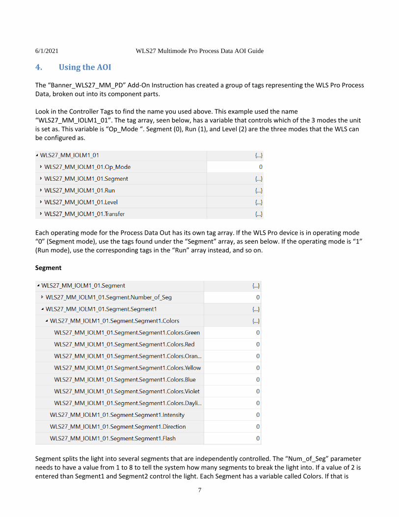
4. Using the AOI The “Banner_WLS27_MM_PD” Add-On Instruction has created a group of tags representing the WLS Pro Process Data, broken out into its component parts. Look in the Controller Tags to find the name you used above. This example used the name “WLS27_MM_IOLM1_01”. The tag array, seen below, has a variable that controls which of the 3 modes the unit is set as. This variable is “Op_Mode “. Segment (0), Run (1), and Level (2) are the three modes that the WLS can be configured as.
Each operating mode for the Process Data Out has its own tag array. If the WLS Pro device is in operating mode “0” (Segment mode), use the tags found under the “Segment” array, as seen below. If the operating mode is “1” (Run mode), use the corresponding tags in the “Run” array instead, and so on. Segment
Segment splits the light into several segments that are independently controlled. The “Num_of_Seg” parameter needs to have a value from 1 to 8 to tell the system how many segments to break the light into. If a value of 2 is entered than Segment1 and Segment2 control the light. Each Segment has a variable called Colors. If that is

6/1/2021 WLS27 Multimode Pro Process Data AOI Guide
8
expanded all the available colors for the segment are given. By setting the value to 1 the color will activate. Only one color can be activated at a time for proper operation. The intensity of the light will be Normal when Intensity is set to 0, while it will be low when set to 1. The Flash parameter controls if the light should flash or not. When set to 0 the light is solid, while when set to 1 it will flash. The Direction parameter is not used in segment mode.
Run
Run mode scrolls a bar across the light when in operation. The scrolling bar’s color is set via the Running tag. When that is expanded there is a list of colors. Set the color that the scrolling bar should be to 1. A background color is also required. Just like Running it can be set to any of the colors. Tags “Intensity_Running” and “Intensity_Background” control the intensity of the light. Set them to 1 for lower intensity. Finally, the Direction tag can swap the direction of the scrolling bar . Level
Level mode starts with the light having a single color. As the Level Value is increased the light will start to change the color of the LEDs. This can be used to show the level of materials in the system. Background controls the default state of the LEDs. Base controls the LEDs as the Level Value is increased until one of the Threshold settings takes over.

6/1/2021 WLS27 Multimode Pro Process Data AOI Guide
9
Threshold has a CC tag when expanded allows a color to be set. Setting “Threshold_Enable” is set to 1 the current threshold is activated. “Threshold_Overide” controls if the threshold color overrides the current colors or if they are retained. “Threshold_Comparison” when set to 0 does a less than or equal comparison, while a value of 1 does a greater than or equal comparison of the “Threshold_Value” to the “Level_Value”. Finally, the “Threhsold_Value” is the value that is used during the comparison.
That completes how the AOI is used.

6/1/2021 WLS27 Multimode Pro Process Data AOI Guide
10
Appendix A IO-Link Master Cheat Sheet
Different IO-Link Masters behave differently in several ways. For one, the register locations where Process Data is stored varies. For another, some IO-Link Masters require byte-swapping and/or word-swapping. The tables below aim to define some of these differences. Note that these numbers are when using all default settings. IO-Link Masters can change the register locations to which Process Data is mapped in response to non-default, optional settings. See relevant IO-Link Master documentation for more information. PDI (Process Data In) is found in the IO-Link Master’s T->O (PLC “Input”) Assembly Instance. PDO (Process Data Out) is found in the IO-Link Master’s O->T (PLC “Output”) Assembly Instance. Table 1. First Register of Process Data “SINT0”
Port
Allen-Bradley* Comtrol Balluff Turck ifm
PDI PDO PDI PDO PDI PDO PDI PDO PDI PDO
1 I.Ch0Data[0] O.Ch0Data[0] 4 0 8 6 6 4 190 46
2 I.Ch1Data[0] O.Ch1Data[0] 40 32 56 38 38 36 222 78
3 I.Ch2Data[0] O.Ch2Data[0] 76 64 104 70 70 68 254 110
4 I.Ch3Data[0] O.Ch3Data[0] 112 96 152 102 102 100 286 142
5 I.Ch4Data[0] O.Ch4Data[0] 148 128 200 134 134 132 318 174
6 I.Ch5Data[0] O.Ch5Data[0] 184 160 248 166 166 164 250 206
7 I.Ch6Data[0] O.Ch6Data[0] 220 192 296 198 198 196 382 238
8 I.Ch7Data[0] O.Ch7Data[0] 256 224 344 230 230 228 414 270
*see relevant Banner Allen-Bradley IO-Link Master AOI Guide and Allen-Bradley User Guides for more information on using device IODD files to aid in integration. Table 2. Byte-Swap
IO-Link Master
Byte Swap
Allen-Bradley 0
Comtrol 1
Balluff 0
Turck 1
ifm 1
Specific hardware used in both tables (all default settings): Allen-Bradley Armor Block I/O IO-Link Master (1732E-8IOLM12R) Comtrol 8-EIP IO-Link Master (99608-8) Balluff BNI006A (BNI EIP-508-105-Z015) Turck TBEN-L5-8IOL ifm AL1122