wld 257 tp - request a spot account - web services at pccspot.pcc.edu/welding/pdfs/257tp.pdf ·...
TRANSCRIPT

WLD 257
Preparation for Pipe Certification II
WLD 257 6/11/12
Matt Scott
2
Index Pages
Course Information 3
Science on Steel
4-10
Pipe Prep and Welding Information
Sheets
11-37
Craftsmanship Expectations 38
Welding Projects
39-42
Final Exam Information
43-49
Assessment Breakdown for the Course
50
Video Training Pipe Welding Made Easy
SMAW E6010/E7018 6G
SMAW E6010/E7018 5G
Located in the Welding Resource Room
This project was supported, in part,
by the
National Science Foundation Opinions expressed are those of the authors
And not necessarily those of the Foundation

WLD 257 6/11/12
Matt Scott
3
Course Assignments
Reading
WLD 257 Information Sheets
Welding Projects
6G Butt - Single Vee Grove Weld - Open Root - Pipe Weld
5G Butt - Single Vee Grove Weld - Open Root - Pipe Weld
Video Training
Pipe Welding Made Easy E6010/E7018 6G
Pipe Welding Made Easy E6010/E7018 5G
Final Exam
Part One (Closed Book Exam)
Part Two (Practical Exam)
Outcome Assessment Policy:
The student will be assessed on his/her ability to demonstrate the achievement of course
outcomes. The methods of assessment may include one or more of the following: oral or
written examinations, quizzes, written assignments, visual inspection techniques, welding
tests, safe work habits, task performance and work relations.
Grading criteria:
The student's assessment will be based on the following criteria:
15% of grade is based on safe work habits and shop practices.
20% of grade is based on completion of written and reading assignments.
15% of grade is based on demonstrating professional work ethics.
40% of grade is based on completion of welding exercises.
10% based on final exam/project

WLD 257 6/11/12
Matt Scott
4
Science
on
Steel
The Welding Fabrication Industry needs qualified welder fabricators who can deal with a
variety of situations on the job. This portion of the training packet explores science as it
relates to industry requirements.

WLD 257 6/11/12
Matt Scott
5
E6010/E7018 Pipe Certification
Contents of this Packet
- Introduction
- Importance of Code Qualification
- Mechanical Properties Testing for Pipe Welding Qualification
- Code Requirements
- Significance of Bend Testing
- Concave Root Surface (Suck Back)
Introduction
This packet covers the welder qualification using the combination of E6010 cellulosic
electrode for the root pass and E7018 low-hydrogen electrodes for subsequent fill passes
deposited in open root pipe welding on mild steel. Although the E6010 and E7018
electrodes operate differently (as discussed in previous science packets), the testing
required for welder qualification for most pipe welding codes are similar. E6010 is the
deepest-penetrating, all-position electrode. To achieve such deep penetration, the highest
amount of cellulose is used in the flux cover. The cellulose also provides large amounts
gaseous shielding with minimal slag. This allows the welder to have a clear view of the
keyhole in open root welding. On the other hand, the fill passes are deposited with
E7018, which is a lime-based, iron-powder, low-hydrogen electrode. Unlike E6010, the
E7018 electrode provides high deposition rate as well as a thick slag to generate the
primary source of shielding. Because E6010 is a high-hydrogen electrode, the welder
must be certain that the code (he/she is using) allows the use of cellulosic electrodes. If
not, all of the passes including the root pass must be deposited with the low-hydrogen
E7018 electrode (even though E6010 is the best electrode for open root welding). In
some cases, the root pass is deposited by gas tungsten arc welding.
Importance of Code Qualification
In all industries, there are applicable codes and standards to assure the quality,
reproducibility, and adequacy of welded joints. Depending upon the application, a
welded joint may need certain mechanical properties; for example, welds on bridges must
pass tests for strength, tensile ductility, bend ductility, and Charpy impact toughness.
These codes are based on many years of experience. Changes to codes are ongoing to
reflect the dynamic changes that taking place in the industry. There are many welding
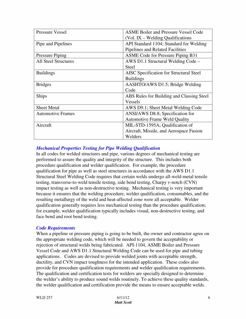
codes to ensure quality welding. For example, the following is a list of only a few typical
industries and governing codes for welding quality.
WLD 257 6/11/12
Matt Scott
6
Pressure Vessel ASME Boiler and Pressure Vessel Code
(Vol. IX – Welding Qualifications
Pipe and Pipelines API Standard 1104; Standard for Welding
Pipelines and Related Facilities
Pressure Piping ASME Code for Pressure Piping B31
All Steel Structures AWS D1.1 Structural Welding Code –
Steel
Buildings AISC Specification for Structural Steel
Buildings
Bridges AASHTO/AWS D1.5; Bridge Welding
Code
Ships ABS Rules for Building and Classing Steel
Vessels
Sheet Metal AWS D9.1; Sheet Metal Welding Code
Automotive Frames ANSI/AWS D8.8; Specification for
Automotive Frame Weld Quality
Aircraft MIL-STD-1595A; Qualification of
Aircraft, Missile, and Aerospace Fusion
Welders
Mechanical Properties Testing for Pipe Welding Qualification
In all codes for welded structures and pipe, various degrees of mechanical testing are
performed to assure the quality and integrity of the structure. This includes both
procedure qualification and welder qualification. For example, the procedure
qualification for pipe as well as steel structures in accordance with the AWS D1.1
Structural Steel Welding Code requires that certain welds undergo all-weld-metal tensile
testing, transverse-to-weld tensile testing, side bend testing, Charpy v-notch (CVN)
impact testing as well as non-destructive testing. Mechanical testing is very important
because it ensures that the welding procedure, welder qualification, consumables, and the
resulting metallurgy of the weld and heat-affected zone were all acceptable. Welder
qualification generally requires less mechanical testing than the procedure qualification;
for example, welder qualification typically includes visual, non-destructive testing, and
face bend and root bend testing.
Code Requirements
When a pipeline or pressure piping is going to be built, the owner and contractor agree on
the appropriate welding code, which will be needed to govern the acceptability or
rejection of structural welds being fabricated. API-1104, ASME Boiler and Pressure
Vessel Code and AWS D1.1 Structural Welding Code can be used for pipe and tubing
applications. Codes are devised to provide welded joints with acceptable strength,
ductility, and CVN impact toughness for the intended application. These codes also
provide for procedure qualification requirements and welder qualification requirements.
The qualification and certification tests for welders are specially designed to determine
the welder’s ability to produce sound welds routinely. To achieve these quality standards,
the welder qualification and certification provide the means to ensure acceptable welds.
WLD 257 6/11/12
Matt Scott
7
Significance of Bend Testing
Of all the tests prescribed by different welding codes, the bend test provides the best and
most reliable measure of ductility of the entire weld joint, including the weld metal, heat-
affected zone, and unaffected base metal. Welder qualification tests in AWS D1.1 always
specify bend testing of welded joints. This is because the bend test is extremely sensitive
to all types of metallurgical problems associated with welding. For example, weld joints
which have inadequate ductility and fail the requirements of the bend test may be due to:
(a) hydrogen assisted cracking, (b) microfissuring due internal solidification cracking, (c)
excessive slag inclusions, (d) excessive porosity, (e) wrong filler metal, causing
embrittlement, (e) wrong welding parameters, causing embrittlement, and (f) other
metallurgical factors affecting the ductility of the weld joint.
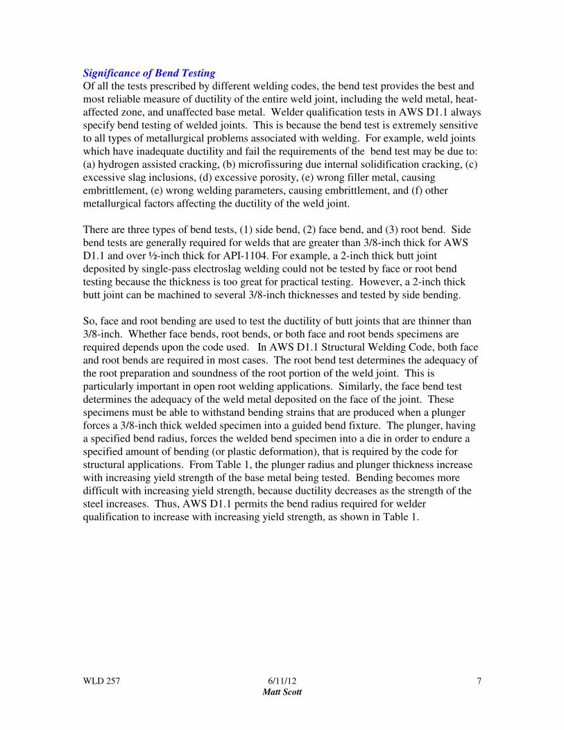
There are three types of bend tests, (1) side bend, (2) face bend, and (3) root bend. Side
bend tests are generally required for welds that are greater than 3/8-inch thick for AWS
D1.1 and over ½-inch thick for API-1104. For example, a 2-inch thick butt joint
deposited by single-pass electroslag welding could not be tested by face or root bend
testing because the thickness is too great for practical testing. However, a 2-inch thick
butt joint can be machined to several 3/8-inch thicknesses and tested by side bending.
So, face and root bending are used to test the ductility of butt joints that are thinner than
3/8-inch. Whether face bends, root bends, or both face and root bends specimens are
required depends upon the code used. In AWS D1.1 Structural Welding Code, both face
and root bends are required in most cases. The root bend test determines the adequacy of
the root preparation and soundness of the root portion of the weld joint. This is
particularly important in open root welding applications. Similarly, the face bend test
determines the adequacy of the weld metal deposited on the face of the joint. These
specimens must be able to withstand bending strains that are produced when a plunger
forces a 3/8-inch thick welded specimen into a guided bend fixture. The plunger, having
a specified bend radius, forces the welded bend specimen into a die in order to endure a
specified amount of bending (or plastic deformation), that is required by the code for
structural applications. From Table 1, the plunger radius and plunger thickness increase
with increasing yield strength of the base metal being tested. Bending becomes more
difficult with increasing yield strength, because ductility decreases as the strength of the
steel increases. Thus, AWS D1.1 permits the bend radius required for welder
qualification to increase with increasing yield strength, as shown in Table 1.

WLD 257 6/11/12
Matt Scott
8
Table 1 Specified Bending Parameters for Guided Bend Test for Steel Welds
in accordance with AWS D1.1 Structural Welding Code - Steel
Yield Strength
Of Base Metal
Plunger
Thickness
Plunger
Radius
Interior Die
Opening
Die Radius
50,000psi and
less
Over 50,000psi
to 90,000psi
90,000psi and
greater
1 ½”
2”
2 ½”
¾”
1”
1 ¼”
2 3/8”
2 7/8”
3 3/8”
1 3/16”
1 7/16”
1 11/16”
Furthermore, the bend test for steel welds is very sensitive to the presence of diffusible
hydrogen in the weld. Even if non-destructive testing shows a welded steel to be crack-
free, the bend test can activate the hydrogen cracking mechanism in steel welds which are
susceptible to hydrogen cracking. Thus, there are many metallurgical causes for lack of
adequate ductility in a welded structure, and the bend test is best suited to separate the
“good” welds from the “bad” welds.
Concave Root Surface (Suck Back)
The root pass of an open root weld often exhibits “suck back” or a concave root surface in
pipe joints as well as open root plate joints. This is due to a complex set of forces, which
simultaneously act upon the molten metal in the bottom of the open root. As the open
root pass begins to solidify, the weld shrinks and the remaining liquid is stretched across
the root face to form a concave root surface or suck-back. The liquid can actually stretch
to some degree without burn-through because surface tension acts to hold the molten
metal together.
The three most important forces acting on the root pass are (1) surface tension of the
molten metal, (2) gravity, and (3) arc force. None of these forces are easily controlled by
the welder. Surface tension is a beneficial property of the molten weld metal, which
tends to hold molten metal together, much like a balloon holds liquid water. Surface
tension forces increase with decreasing temperature of the molten weld metal. Gravity
always tries to oppose the beneficial effects of surface tension of molten metal in the open
root. The effects of gravity are dependent upon the size and weight of the weld pool as
well as the welding position used; for example, flat, compared to overhead, compared to
vertical-up. The larger the weld pool size of the root pass, the more difficult it will be for
surface tension to hold the molten metal in place. Arc force is another complex force,
which is provided by the arc in the direction of arc impingement. Arc force increases
with increasing amperage. Too high an arc force will burn through the root. With
decreasing amperage and decreasing size of root pass, the greater will be the surface
tension forces holding the molten pool in place.

WLD 257 6/11/12
Matt Scott
9
Surface tension is the most important beneficial force, because without surface tension,
open root welding would not be possible. Without surface tension, the molten metal in
the open root would act like water and flow through the root opening. Surface tension is
always trying to keep the molten pool from dripping out of the root area. Imagine a
balloon full of water, the elastic polymer provides the restraining forces to keep the water
in place. If outside forces are too great, the balloon will distort, burst and water will
escape. Similarly, in a full-penetration open-root pass, the heat input must be adjusted so
that surface tension will hold the molten in the open root opening. The smaller the root
pass, the easier it is for surface tension forces to hold the molten metal in place. When
the root pass is deposited by E6010 electrode, just the right amount of heat input is
needed to produce a keyhole in the joint for full penetration. With too little heat, full
penetration will not be achieved; while, with too high heat input, the arc will blow
through the joint. At the optimum level of heat, the molten metal is suspended by surface
tension forces in the gap of the open root. Surface tension forces overcome gravity and
the root pass is achieved.
Quantitatively, the resolved force (F) acting on the weld pool is function of two opposing
factors; surface tension force and gravitational force, as shown below:
F = + P γ - ρ g V
P is the periphery length along the root face, γ is the surface (tension) energy, ρ is the
molten metal density, g is the acceleration of gravity, and V is the volume of molten
metal in the root gap. From this equation, increasing the beneficial surface tension (P γ)
force prevents drop-through or burn-through by holding the molten metal in place. Also,
the fast freezing flux is very helpful in supporting the suspended molten metal between
the two plates. However, the weight of the molten (- ρ g V) is affected by gravity and
tries to prevent successful open root welding. Increasing the heat input promotes larger
molten pool size and higher molten pool temperatures. This causes a reduction in the
surface tension forces holding the weld in place.
How does “suck back” develop in the root and what controls the amount of suck back?
Surface tension is necessary to hold and suspend the molten metal in the open root
without dropping through like water. Surface tension of molten metal in the open root
acts as if the molten metal is in an “impervious bag” which prevents liquid from falling
through the open root. Fortunately, the surface tension of molten iron is very high; for
example, the surface (tension) energy of iron at its melting point is about twice that for
aluminum at its melting point. So during solidification, the shrinkage forces between the
two root faces pull on the molten pool substantially to produce a concave root surface or
suck back. Suck back can be overcome if the welder can provide additional weld metal
into the root. This is dangerous because of the increased chance of drop-through.
Fortunately, in welding, the use of fast freezing fluxes and good welder skill reduce the
occurrence of excessive concave root surfaces.
WLD 257 6/11/12
Matt Scott
10
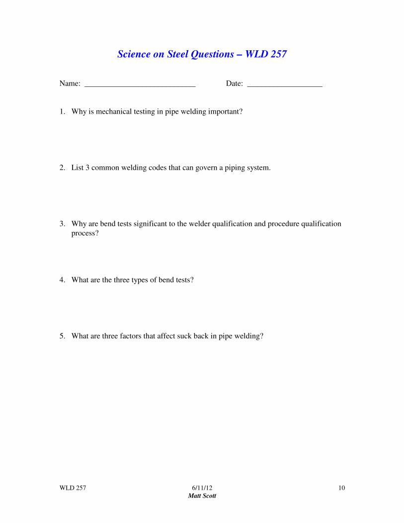
Science on Steel Questions – WLD 257
Name: ____________________________ Date: ___________________
1. Why is mechanical testing in pipe welding important?
2. List 3 common welding codes that can govern a piping system.
3. Why are bend tests significant to the welder qualification and procedure qualification
process?
4. What are the three types of bend tests?
5. What are three factors that affect suck back in pipe welding?
WLD 257 6/11/12
Matt Scott
11
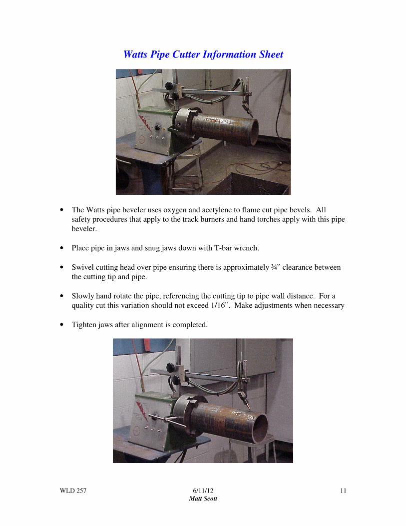
Watts Pipe Cutter Information Sheet
• The Watts pipe beveler uses oxygen and acetylene to flame cut pipe bevels. All
safety procedures that apply to the track burners and hand torches apply with this pipe
beveler.
• Place pipe in jaws and snug jaws down with T-bar wrench.
• Swivel cutting head over pipe ensuring there is approximately ¾” clearance between
the cutting tip and pipe.
• Slowly hand rotate the pipe, referencing the cutting tip to pipe wall distance. For a
quality cut this variation should not exceed 1/16”. Make adjustments when necessary
• Tighten jaws after alignment is completed.
WLD 257 6/11/12
Matt Scott
12
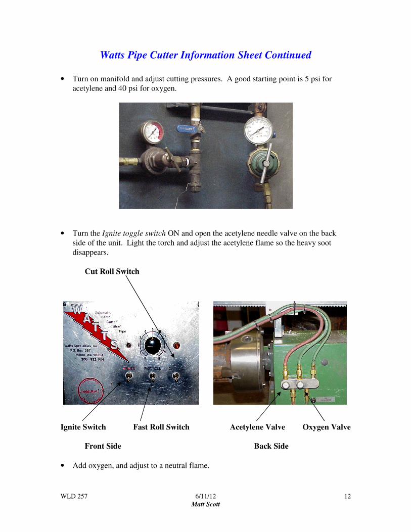
Watts Pipe Cutter Information Sheet Continued
• Turn on manifold and adjust cutting pressures. A good starting point is 5 psi for
acetylene and 40 psi for oxygen.
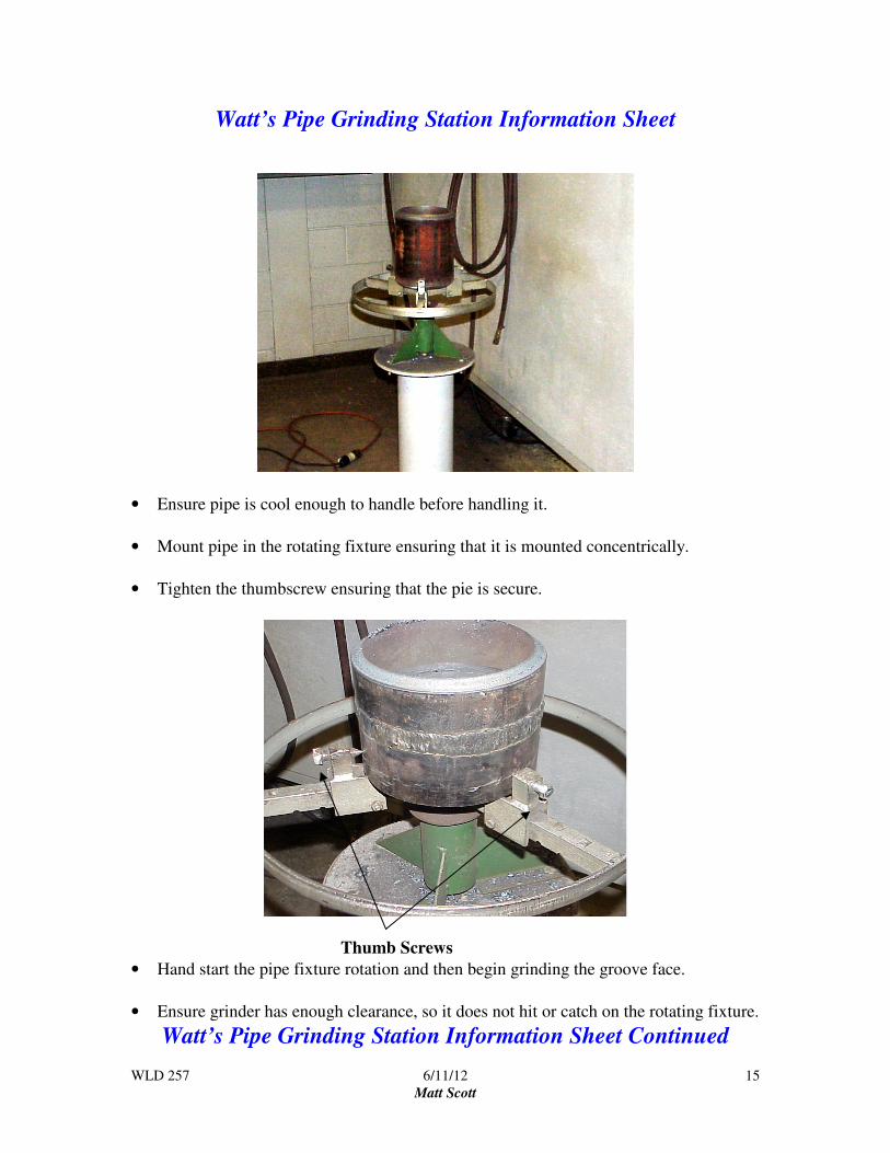
• Turn the Ignite toggle switch ON and open the acetylene needle valve on the back
side of the unit. Light the torch and adjust the acetylene flame so the heavy soot
disappears.
Cut Roll Switch
Ignite Switch Fast Roll Switch Acetylene Valve Oxygen Valve
Front Side Back Side
• Add oxygen, and adjust to a neutral flame.

WLD 257 6/11/12
Matt Scott
13
Watts Pipe Cutter Information Sheet Continued
• Turn the Cut and Roll toggle switch ON and adjust to a neutral flame. When adding
the cutting oxygen, the fuel gas to oxygen ratio changes thus requiring the need to
readjust to a neutral flame.
• Once flame is adjusted, the manual needle valves do not need to be turn off each time.
Use the Ignite toggle switch to turn the torch ON and OFF.
Rotation Speed Control
Ignite Toggle Switch Fast Roll Switch Cut Roll Switch
• Light torch and align head over the pipe. Use the Fast Roll toggle switch and preheat
the pipe by having it rotate 360 degrees. Once pipe is preheated let the torch set idle
over one area to heat the kindling temperature (cherry red).
Helpful Hint: Clamp vice grips at the cutting start point. This is a good visual
reference for when the pipe cut will be completed, as well as a tool to catch the
pipe coupon.
• Once pipe is cherry red, turn the Cut and Roll toggle switch on and the cut will begin.
Helpful Hint: Once flame pierces through the pipe, adjust the torch back slightly
to remove the starting flaw.

WLD 257 6/11/12
Matt Scott
14
Watts Pipe Cutter Information Sheet Continued
Torch Extension Arm
• Once pipe cut is completed, adjust torch extension arm back to make additional cuts
or remove pipe coupon and replace with next coupon and complete the cutting
process.
WLD 257 6/11/12
Matt Scott
15
Watt’s Pipe Grinding Station Information Sheet
• Ensure pipe is cool enough to handle before handling it.
• Mount pipe in the rotating fixture ensuring that it is mounted concentrically.
• Tighten the thumbscrew ensuring that the pie is secure.
Thumb Screws
• Hand start the pipe fixture rotation and then begin grinding the groove face.
• Ensure grinder has enough clearance, so it does not hit or catch on the rotating fixture.
Watt’s Pipe Grinding Station Information Sheet Continued
WLD 257 6/11/12
Matt Scott
16
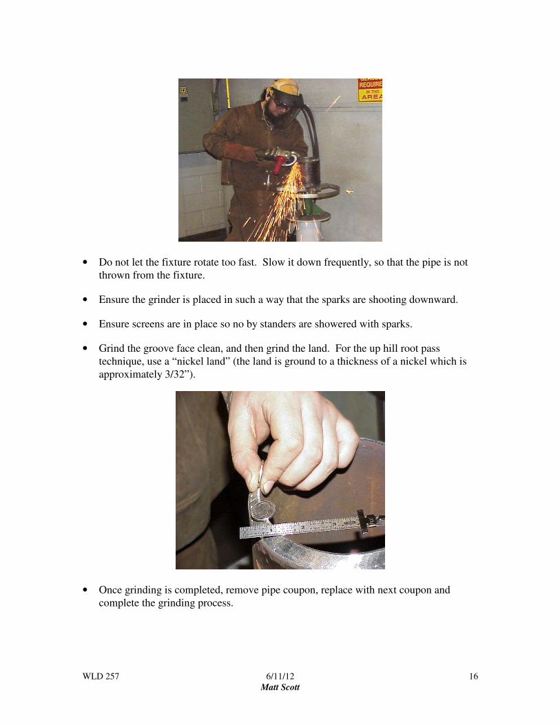
• Do not let the fixture rotate too fast. Slow it down frequently, so that the pipe is not
thrown from the fixture.
• Ensure the grinder is placed in such a way that the sparks are shooting downward.
• Ensure screens are in place so no by standers are showered with sparks.
• Grind the groove face clean, and then grind the land. For the up hill root pass
technique, use a “nickel land” (the land is ground to a thickness of a nickel which is
approximately 3/32”).
• Once grinding is completed, remove pipe coupon, replace with next coupon and
complete the grinding process.
WLD 257 6/11/12
Matt Scott
17
Fitting Up the Pipe
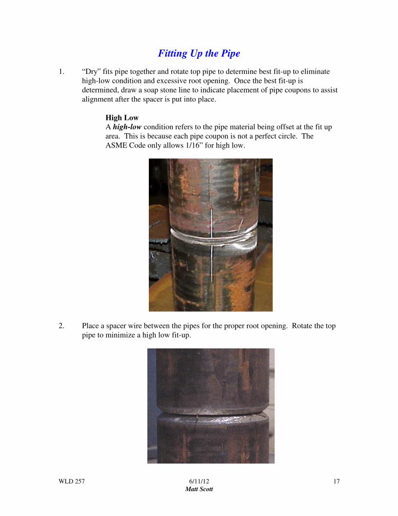
1. “Dry” fits pipe together and rotate top pipe to determine best fit-up to eliminate
high-low condition and excessive root opening. Once the best fit-up is
determined, draw a soap stone line to indicate placement of pipe coupons to assist
alignment after the spacer is put into place.
High Low
A high-low condition refers to the pipe material being offset at the fit up
area. This is because each pipe coupon is not a perfect circle. The
ASME Code only allows 1/16” for high low.
2. Place a spacer wire between the pipes for the proper root opening. Rotate the top
pipe to minimize a high low fit-up.

WLD 257 6/11/12
Matt Scott
18
3. Make the first tack weld ½” long between the open ends of the spacer wire. The
first tack should only be ½” long to help control distortion. The remaining three
tacks should be ¾” long.
4. Remove the spacer wire and reposition it as shown, and weld the second tack
opposite the first tack (this is referred to as diametrically opposed to the first tack).

WLD 257 6/11/12
Matt Scott
19
5. Tack weld the two remaining sides starting with the wider of the two sides. At
this point the pipe should have one tack weld at 12, 3, 6 and 9 o’clock positions.
6. Use a hand grinder with a 1/8” thick notching wheel to feather (ramp) the tacks.
The keyhole side of the tack will not need as much grinding. Too much grinding
on this end of the tack will potentially cause burn through when welding the root
pass.
Minimal grinding at the key hole end

WLD 257 6/11/12
Matt Scott
20
Pipe Welding Power Tools
At a minimum a pipe welder should have:
• Two 9 inch grinder for pipe that is 6 inches and larger (one with a notching wheel
and one with a wire wheel).
• Two 4½ inch grinder for 4 inch pipe and smaller (one with a notching wheel and one
with a wire wheel).
• File with “teeth ground in it” used for slag removal (Do Not Use a Chipping
hammer on Pipe).
• Flash light for inspection purposes.

WLD 257 6/11/12
Matt Scott
21
6G Welding Techniques
1. Secure the pipe in the fixture in the 6G position to be welded.
6G Position
Pipe axis is inclined 45 degrees from the horizontal plane
1. Strike the arc and extend the arc length (“long arc”) over the tack weld and allow
electrode to "warm up.” "Pop" the electrode into open root and pause slightly, and
begin welding. Note that the Arc is “burning” through the root opening getting
complete penetration. This is seen by the keyhole that the arc creates.
Strike the arc on the tack weld The “fire” is inside of the pipe.
WLD 257 6/11/12
Matt Scott
22
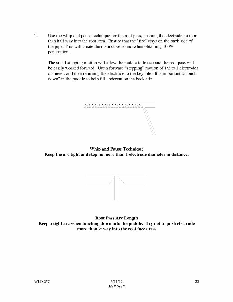
2. Use the whip and pause technique for the root pass, pushing the electrode no more
than half way into the root area. Ensure that the "fire" stays on the back side of
the pipe. This will create the distinctive sound when obtaining 100%
penetration.
The small stepping motion will allow the puddle to freeze and the root pass will
be easily worked forward. Use a forward “stepping” motion of 1/2 to 1 electrodes
diameter, and then returning the electrode to the keyhole. It is important to touch
down" in the puddle to help fill undercut on the backside.
Whip and Pause Technique
Keep the arc tight and step no more than 1 electrode diameter in distance.
Root Pass Arc Length
Keep a tight arc when touching down into the puddle. Try not to push electrode
more than ½ way into the root face area.

WLD 257 6/11/12
Matt Scott
23
Use the two handed technique to strike
the arc. This will help eliminate arc
strikes on the pipe wall that will render
the pipe useless.
This technique is sometimes referred to
as “shooting pool.”
While welding keep the root pass
centered in the root opening and moving
forward. There is nothing but the
puddle to catch itself on the backside of
an open root weld so a slow travel speed
will lead to excessive root reinforcement.
Note that the lumpy areas are not
detrimental since the root pass will be
ground before applying the hot pass
Five variables to control when applying the root pass:
• Root face
• Root opening
• Amperage
• Arc length
• Travel speed
The soundness of the root pass will be greatly affected by these five variables. The
welder will need to learn to control these variables to produce a quality root bead.

WLD 257 6/11/12
Matt Scott
24
Root Bead Suggestions:
• Center root pass (stringer) in the root opening when welding, this will help prevent
internal undercut or inadequate penetration (IP).
• Keep the bead moving
• Avoid letting the key hole get too large
• Vary technique for joint fit up.
Adjust Technique for Root Fit Up to ensure 100% penetration
Narrow gap techniques:
• Push electrode into opening to “burn through”
• Increase amperage
• Grind root area to reduce root land
Wide gap technique:
• Weld wide section last. Hopefully welding the other three quadrants will shrink wide
area.
• Reduce current
• Use U-weave whip and pause technique
• Allow the pipe to cool.
Internal Undercut:
• Electrode too deep into groove
• Amperage too high
• Root opening too large
• Root land too thin
Stopping techniques
Use a quick step out of the root bead to decrease keyhole size when terminating
the weld. Leaving a large keyhole can cause excessive root reinforcement on the
inside.
WLD 257 6/11/12
Matt Scott
25
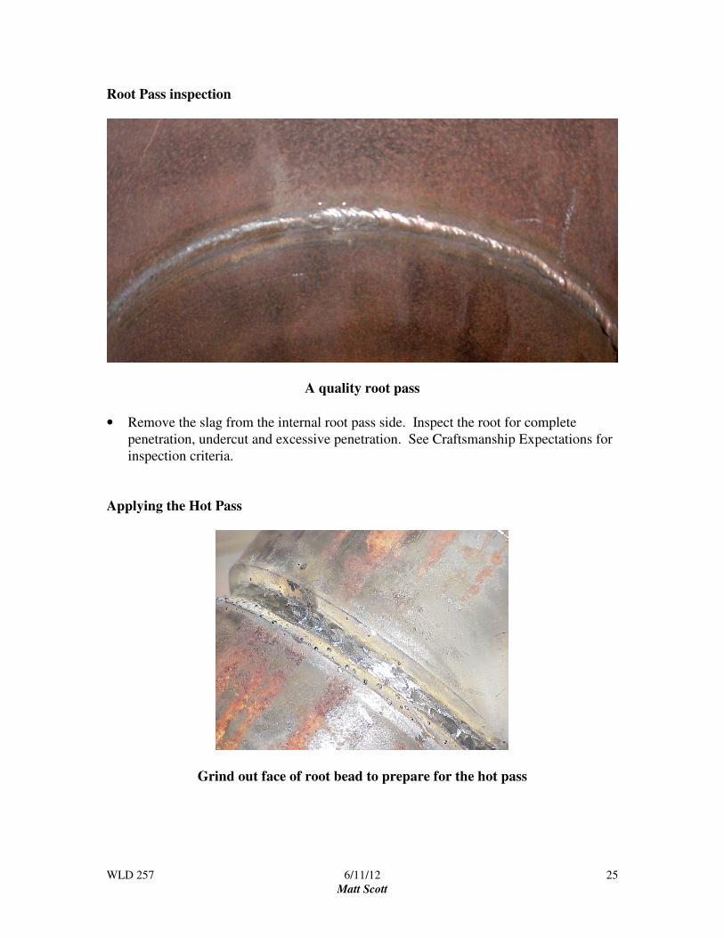
Root Pass inspection
A quality root pass
• Remove the slag from the internal root pass side. Inspect the root for complete
penetration, undercut and excessive penetration. See Craftsmanship Expectations for
inspection criteria.
Applying the Hot Pass
Grind out face of root bead to prepare for the hot pass
WLD 257 6/11/12
Matt Scott
26
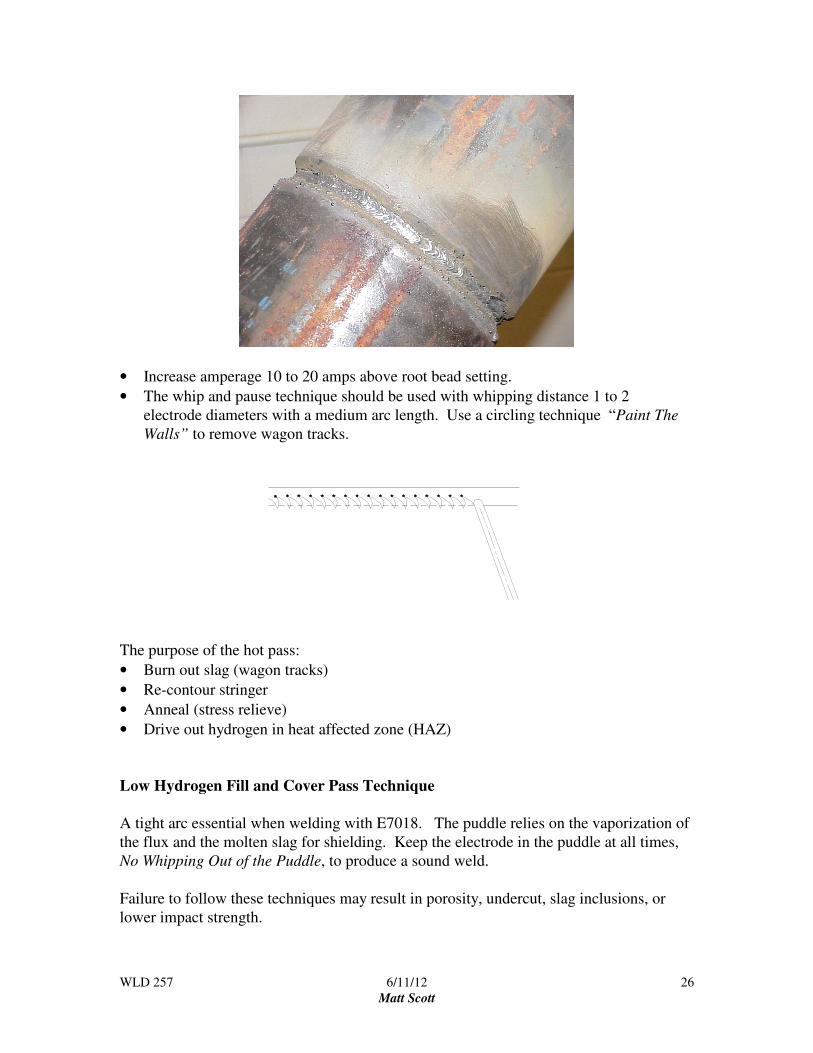
• Increase amperage 10 to 20 amps above root bead setting.
• The whip and pause technique should be used with whipping distance 1 to 2
electrode diameters with a medium arc length. Use a circling technique “Paint The
Walls” to remove wagon tracks.
The purpose of the hot pass:
• Burn out slag (wagon tracks)
• Re-contour stringer
• Anneal (stress relieve)
• Drive out hydrogen in heat affected zone (HAZ)
Low Hydrogen Fill and Cover Pass Technique
A tight arc essential when welding with E7018. The puddle relies on the vaporization of
the flux and the molten slag for shielding. Keep the electrode in the puddle at all times,
No Whipping Out of the Puddle, to produce a sound weld.
Failure to follow these techniques may result in porosity, undercut, slag inclusions, or
lower impact strength.

WLD 257 6/11/12
Matt Scott
27
First layer of the 7018 fill pass
• Use the slant loop technique to cover the whole hot pass. Pause at the side walls and
not the middle of the puddle.
• Remove all slag prior to applying next layer
Second layer of the 7018 fill pass:
• Use the slant loop multiple pass stringer bead technique for the second layer of fill
beads.
• Ensure to leave enough area for the second pass on this layer. If the first bead is too
large there will not be enough room for the second bead to go in with out trapping
slag.
• Remove all slag prior to applying next layer.
WLD 257 6/11/12
Matt Scott
28
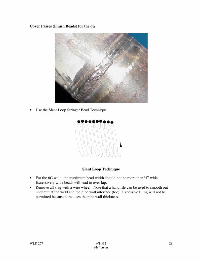
Cover Passes (Finish Beads) for the 6G
• Use the Slant Loop Stringer Bead Technique
Slant Loop Technique
• For the 6G weld, the maximum bead width should not be more than ½” wide.
Excessively wide beads will lead to over lap.
• Remove all slag with a wire wheel. Note that a hand file can be used to smooth out
undercut at the weld and the pipe wall interface (toe). Excessive filing will not be
permitted because it reduces the pipe wall thickness.

WLD 257 6/11/12
Matt Scott
29
5G Welding Techniques
1. Tack weld pipe coupons together and secure the pipe in the fixture in the 5G
position to be welded.
5G Position
Pipe axis is parallel to the horizontal plane
and the pipe is not rotated
2. When applying the root pass, strike the arc and extend the arc length (“long arc”)
over the tack weld and allow electrode to "warm up.” "Pop" the electrode into
open root and pause slightly, and begin welding. Note that the Arc is “burning”
through the root opening getting complete penetration. This is seen by the keyhole
that the arc creates while welding.
Strike the arc on the tack weld
The “fire” is inside of the pipe which
creates a distinctive beehive sound
WLD 257 6/11/12
Matt Scott
30
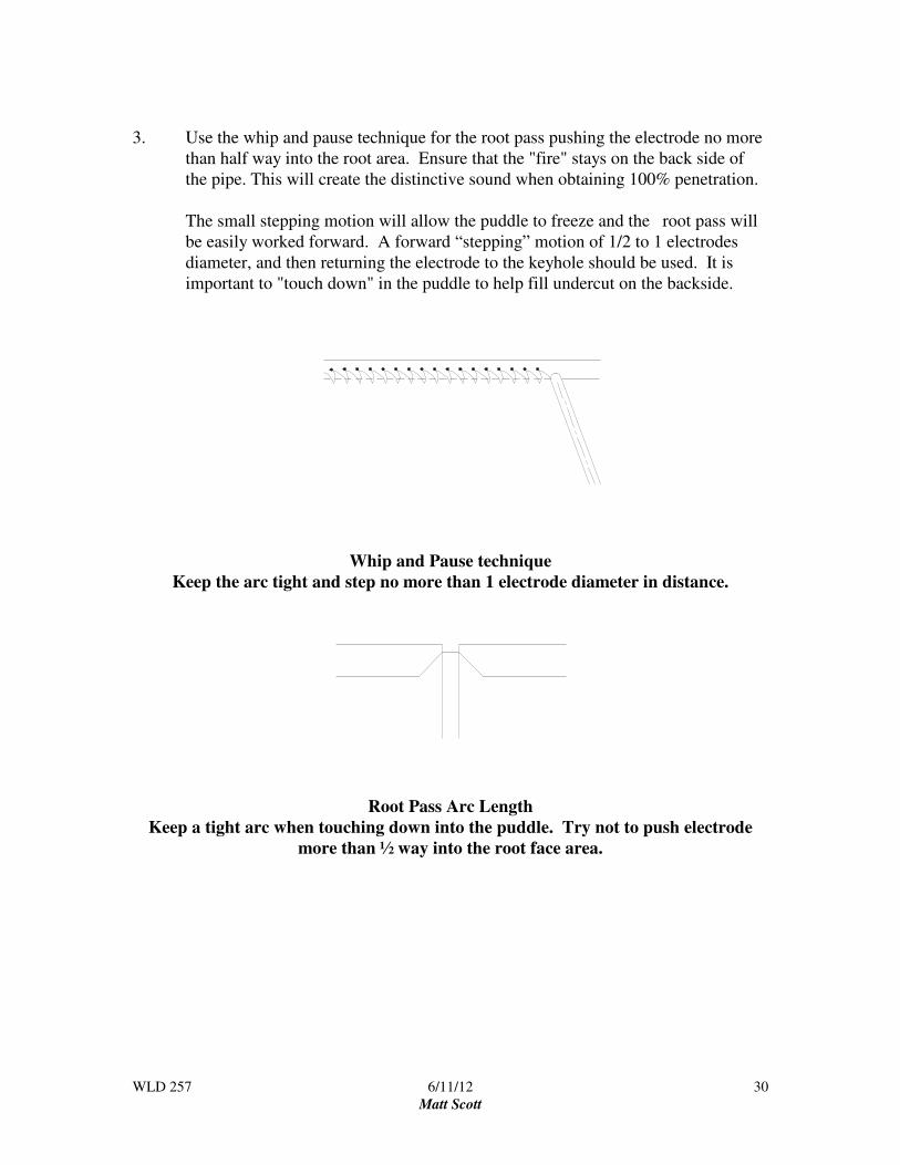
3. Use the whip and pause technique for the root pass pushing the electrode no more
than half way into the root area. Ensure that the "fire" stays on the back side of
the pipe. This will create the distinctive sound when obtaining 100% penetration.
The small stepping motion will allow the puddle to freeze and the root pass will
be easily worked forward. A forward “stepping” motion of 1/2 to 1 electrodes
diameter, and then returning the electrode to the keyhole should be used. It is
important to "touch down" in the puddle to help fill undercut on the backside.
Whip and Pause technique
Keep the arc tight and step no more than 1 electrode diameter in distance.
Root Pass Arc Length
Keep a tight arc when touching down into the puddle. Try not to push electrode
more than ½ way into the root face area.
WLD 257 6/11/12
Matt Scott
31
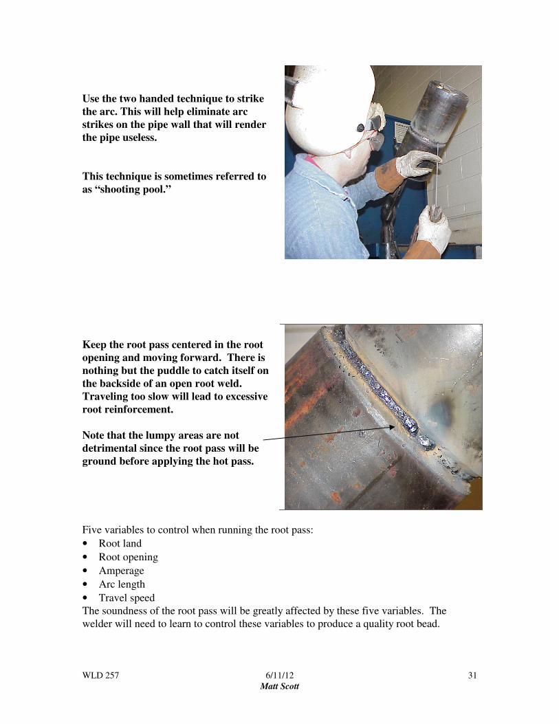
Use the two handed technique to strike
the arc. This will help eliminate arc
strikes on the pipe wall that will render
the pipe useless.
This technique is sometimes referred to
as “shooting pool.”
Keep the root pass centered in the root
opening and moving forward. There is
nothing but the puddle to catch itself on
the backside of an open root weld.
Traveling too slow will lead to excessive
root reinforcement.
Note that the lumpy areas are not
detrimental since the root pass will be
ground before applying the hot pass.
Five variables to control when running the root pass:
• Root land
• Root opening
• Amperage
• Arc length
• Travel speed
The soundness of the root pass will be greatly affected by these five variables. The
welder will need to learn to control these variables to produce a quality root bead.

WLD 257 6/11/12
Matt Scott
32
Root Bead Suggestions:
• Center root pass (stringer) when welding, this will help prevent internal undercut or
inadequate penetration (IP).
• Keep the bead moving
• Avoid letting the key hole get too large
• Vary technique for joint fit up.
Adjust Technique for Root Fit Up to ensure 100% penetration
Narrow gap techniques:
• Push electrode into opening to “burn through”
• Increase amperage
• Grind root area to reduce root land
Wide gap technique:
• Weld wide section last. Hopefully welding the other three quadrants will shrink wide
area.
• Reduce current
• Use U-weave whip and pause technique
• Allow pipe to cool.
Internal Undercut:
• Electrode too deep into groove
• Amperage too high
• Root opening too large
• Root land too thin
Stopping techniques
Use a quick step out of the root bead to decrease keyhole size when terminating
the weld. Leaving a large keyhole can cause excessive root reinforcement on the
inside.
WLD 257 6/11/12
Matt Scott
33
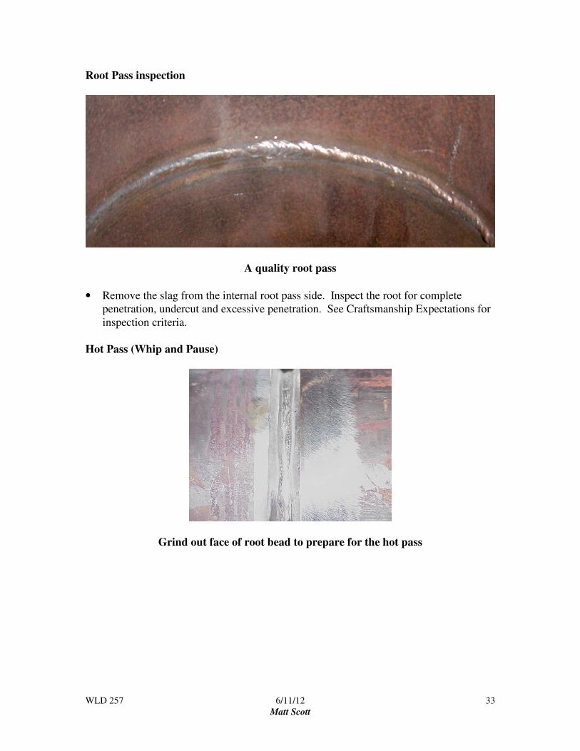
Root Pass inspection
A quality root pass
• Remove the slag from the internal root pass side. Inspect the root for complete
penetration, undercut and excessive penetration. See Craftsmanship Expectations for
inspection criteria.
Hot Pass (Whip and Pause)
Grind out face of root bead to prepare for the hot pass

WLD 257 6/11/12
Matt Scott
34
Applying the Hot Pass
• Increase amperage 10 to 20 amps above root bead setting.
• The whip and pause technique should be used with whipping distance 1 to 2
electrode diameters with a medium arc length. Use a circling whip and pause
technique to “Paint The Walls” to remove wagon tracks.
The purpose of the hot pass is to:
• Burn out slag (wagon tracks)
• Re-contour stringer
• Anneal (stress relieve)
• Drive out hydrogen in heat affected zone (HAZ)
Low Hydrogen Fill and Cover Pass Technique
A tight arc essential when welding with E7018. The puddle relies on the vaporization of
the flux and the molten slag for shielding. Keep the electrode in the puddle at all times,
No Whipping Out of the Puddle, to a produce a sound weld.
Failure to follow these techniques may result in porosity, undercut, slag inclusions, or
lower impact strength.

WLD 257 6/11/12
Matt Scott
35
First layer of the E7018 fill pass
• Use the side-to-side weave technique to cover the whole hot pass. Emphasize the side
walls when welding not the middle of the puddle.
• Remove all slag prior to applying next layer
Second layer of the E7018 fill pass:
• Use the side-to-side weave bead technique for the second layer fill bead.
• Ensure to leave enough area for the cover pass.
• Remove all slag prior to applying next layer.
Example of the side-to-side technique for
the fill passes.
WLD 257 6/11/12
Matt Scott
36
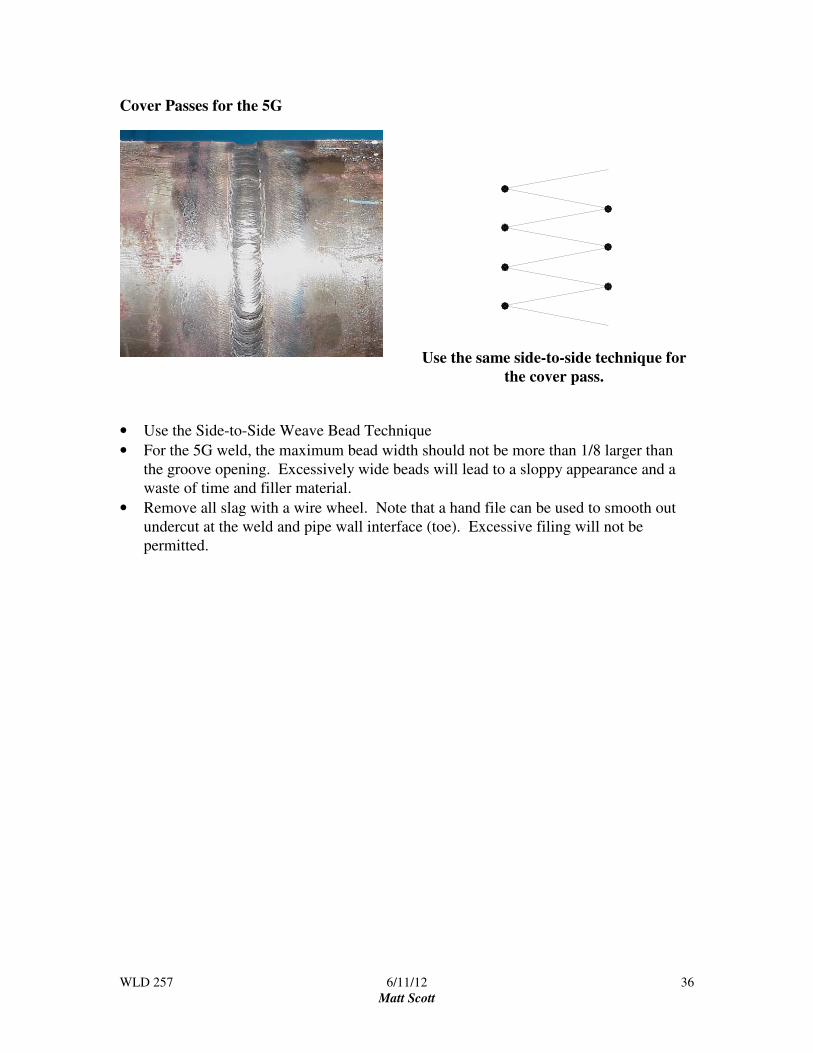
Cover Passes for the 5G
Use the same side-to-side technique for
the cover pass.
• Use the Side-to-Side Weave Bead Technique
• For the 5G weld, the maximum bead width should not be more than 1/8 larger than
the groove opening. Excessively wide beads will lead to a sloppy appearance and a
waste of time and filler material.
• Remove all slag with a wire wheel. Note that a hand file can be used to smooth out
undercut at the weld and pipe wall interface (toe). Excessive filing will not be
permitted.
WLD 257 6/11/12
Matt Scott
37
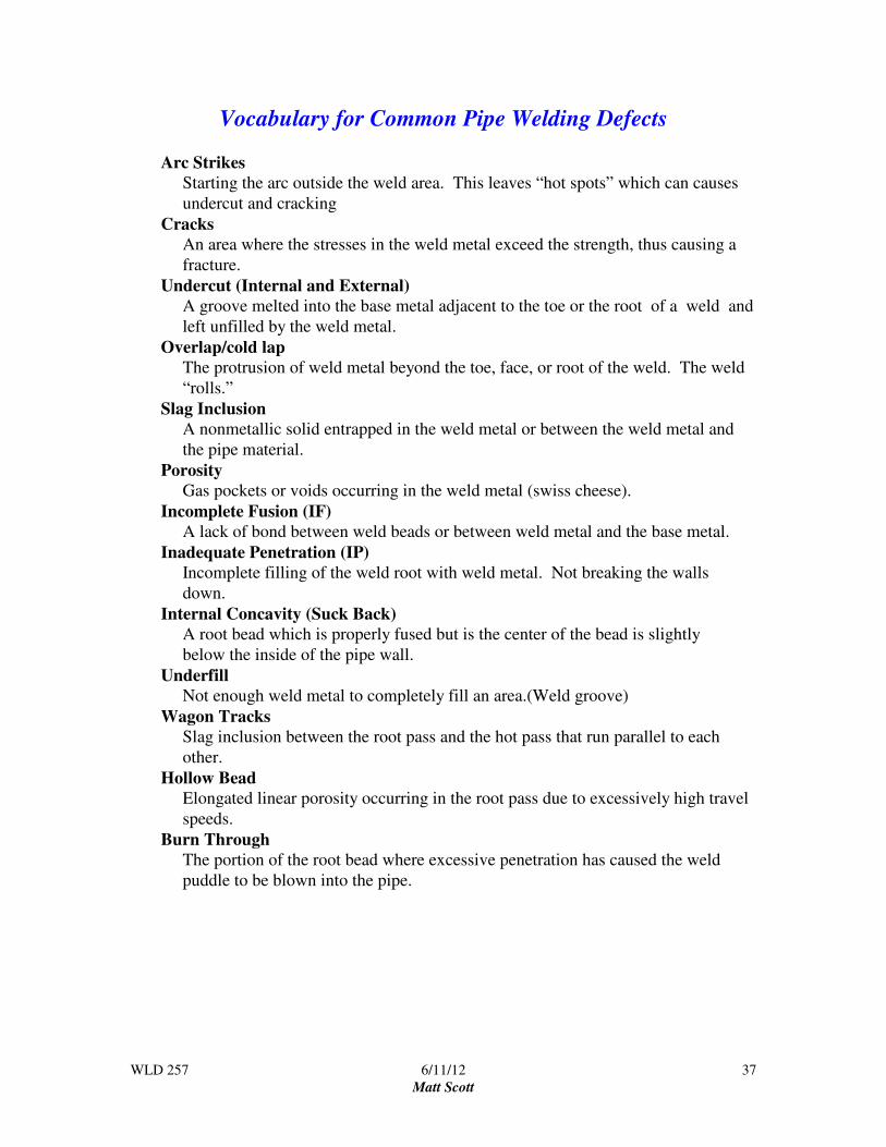
Vocabulary for Common Pipe Welding Defects
Arc Strikes
Starting the arc outside the weld area. This leaves “hot spots” which can causes
undercut and cracking
Cracks
An area where the stresses in the weld metal exceed the strength, thus causing a
fracture.
Undercut (Internal and External)
A groove melted into the base metal adjacent to the toe or the root of a weld and
left unfilled by the weld metal.
Overlap/cold lap
The protrusion of weld metal beyond the toe, face, or root of the weld. The weld
“rolls.”
Slag Inclusion
A nonmetallic solid entrapped in the weld metal or between the weld metal and
the pipe material.
Porosity
Gas pockets or voids occurring in the weld metal (swiss cheese).
Incomplete Fusion (IF)
A lack of bond between weld beads or between weld metal and the base metal.
Inadequate Penetration (IP)
Incomplete filling of the weld root with weld metal. Not breaking the walls
down.
Internal Concavity (Suck Back)
A root bead which is properly fused but is the center of the bead is slightly
below the inside of the pipe wall.
Underfill
Not enough weld metal to completely fill an area.(Weld groove)
Wagon Tracks
Slag inclusion between the root pass and the hot pass that run parallel to each
other.
Hollow Bead
Elongated linear porosity occurring in the root pass due to excessively high travel
speeds.
Burn Through
The portion of the root bead where excessive penetration has caused the weld
puddle to be blown into the pipe.
WLD 257 6/11/12
Matt Scott
38
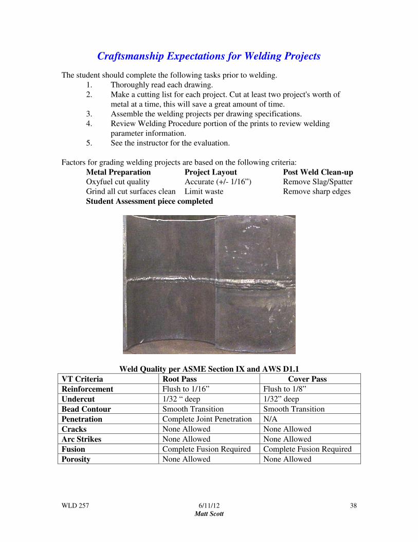
Craftsmanship Expectations for Welding Projects
The student should complete the following tasks prior to welding.
1. Thoroughly read each drawing.
2. Make a cutting list for each project. Cut at least two project's worth of
metal at a time, this will save a great amount of time.
3. Assemble the welding projects per drawing specifications.
4. Review Welding Procedure portion of the prints to review welding
parameter information.
5. See the instructor for the evaluation.
Factors for grading welding projects are based on the following criteria:
Metal Preparation Project Layout Post Weld Clean-up
Oxyfuel cut quality Accurate (+/- 1/16”) Remove Slag/Spatter
Grind all cut surfaces clean Limit waste Remove sharp edges
Student Assessment piece completed
Weld Quality per ASME Section IX and AWS D1.1
VT Criteria Root Pass Cover Pass
Reinforcement Flush to 1/16” Flush to 1/8”
Undercut 1/32 “ deep 1/32” deep
Bead Contour Smooth Transition Smooth Transition
Penetration Complete Joint Penetration N/A
Cracks None Allowed None Allowed
Arc Strikes None Allowed None Allowed
Fusion Complete Fusion Required Complete Fusion Required
Porosity None Allowed None Allowed

WLD 257 6/11/12
Matt Scott
39
E6010/E7018 Butt Joint- Single Vee (6G) Project #1 Welding Sequence
E6010-- Root Pass Utilize the "key hole" technique
E6010-- Hot Pass Increase amperage 10 to 20 amps above root bead setting. Use the
whip and pause technique to “Paint the walls” to burn out wagon
tracks.
E7018-- Fill and Cap Keep a tight arc length when welding- No Whipping. Use
the slant loop oscillation technique.
________________________________________________________________________
Weld Quality per ASME Section IX and AWS D1.1
VT Criteria Root Pass Cover Pass
Reinforcement
Undercut
Bead Contour
Penetration N/A
Cracks
Arc Strikes
Fusion
Porosity
Grade and Date

WLD 257 6/11/12
Matt Scott
40

WLD 257 6/11/12
Matt Scott
41
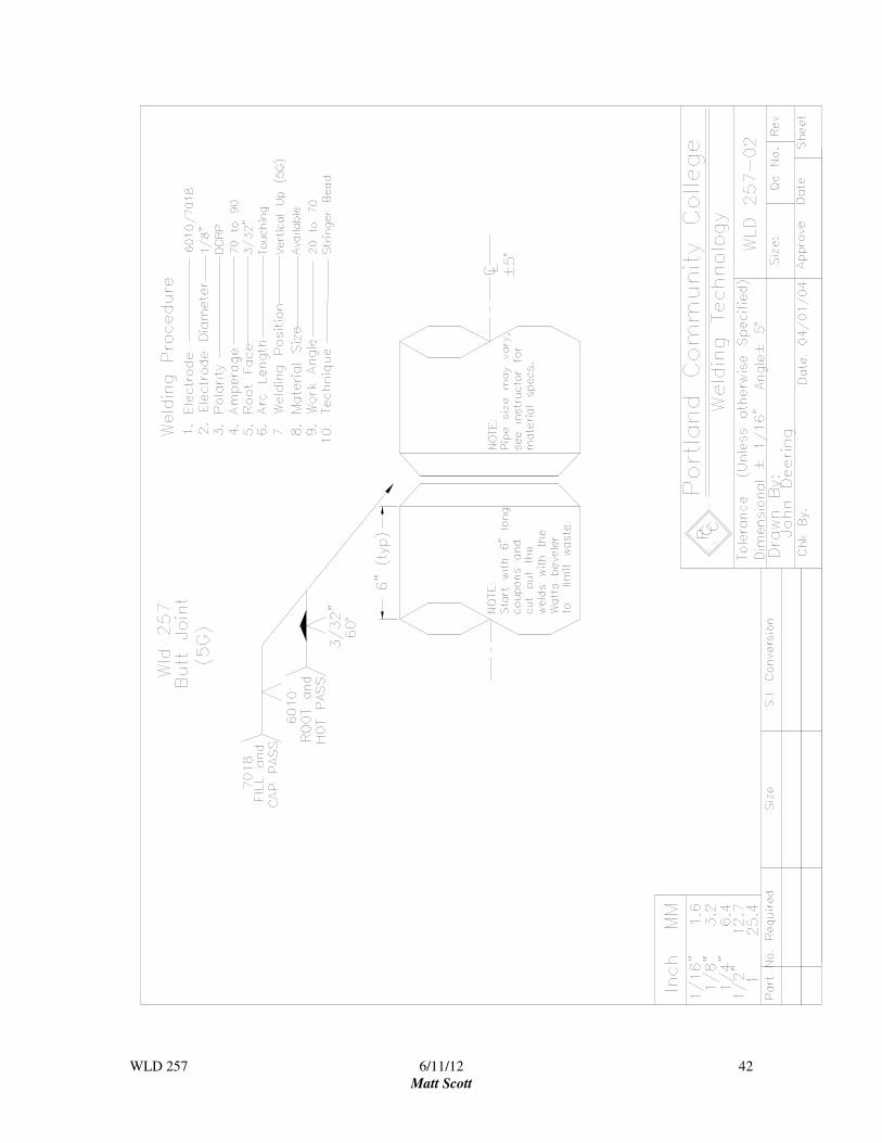
E6010/7018 Butt Joint- Single Vee (5G) Project #2 Welding Sequence
E6010-- Root Pass Utilize the "key hole" technique
E6010-- Hot Pass Increase amperage 10 to 20 amps above root bead setting. Use the
whip and pause technique to “Paint the walls” to burn out wagon
tracks.
E7018-- Fill and Cap Keep a tight arc length when welding- No Whipping. Use
the side-to-side or circular weave technique.
________________________________________________________________________
Weld Quality per ASME Section IX and AWS D1.1
VT Criteria Root Pass Cover Pass
Reinforcement
Undercut
Bead Contour
Penetration N/A
Cracks
Arc Strikes
Fusion
Porosity
Grade and Date
WLD 257 6/11/12
Matt Scott
42

WLD 257 6/11/12
Matt Scott
43
Final Exam
Part One
This portion of the final exam is a closed book test. Consult with your instructor to
determine items that you may need to review. Once you determine that you are ready for
the exam, request it from your instructor. Complete the exam and write all answers on
the answer sheet. Once completed, return the exam and the answer sheet to your
instructor.
Study Guide
Safety
• Oxyacetylene safety
• SMAW safety
• Hand Tool Safety
SMAW and OAC Processes
• Power source specifics
o Polarity
o Current out put
• AWS electrode classification
• OAC
o Theory of cutting
o Flame types
Welding Symbols and Blueprints
• Orthographic views
• Isometric views
• Welding symbol
o Weld symbols
o Reference line
o Tail
Math and Math conversions
� Adding and subtracting fractions
� Reading a tape measure
� Metric conversions
WLD 257 6/11/12
Matt Scott
44
WLD 257 Answer Sheet
Name: _____________________________________ Date: ___________________
1.
11.
2.
12.
3.
13.
4.
14.
5.
15.
6.
16.
7.
17.
8.
18.
9.
19.
10.
20.

WLD 257 6/11/12
Matt Scott
45
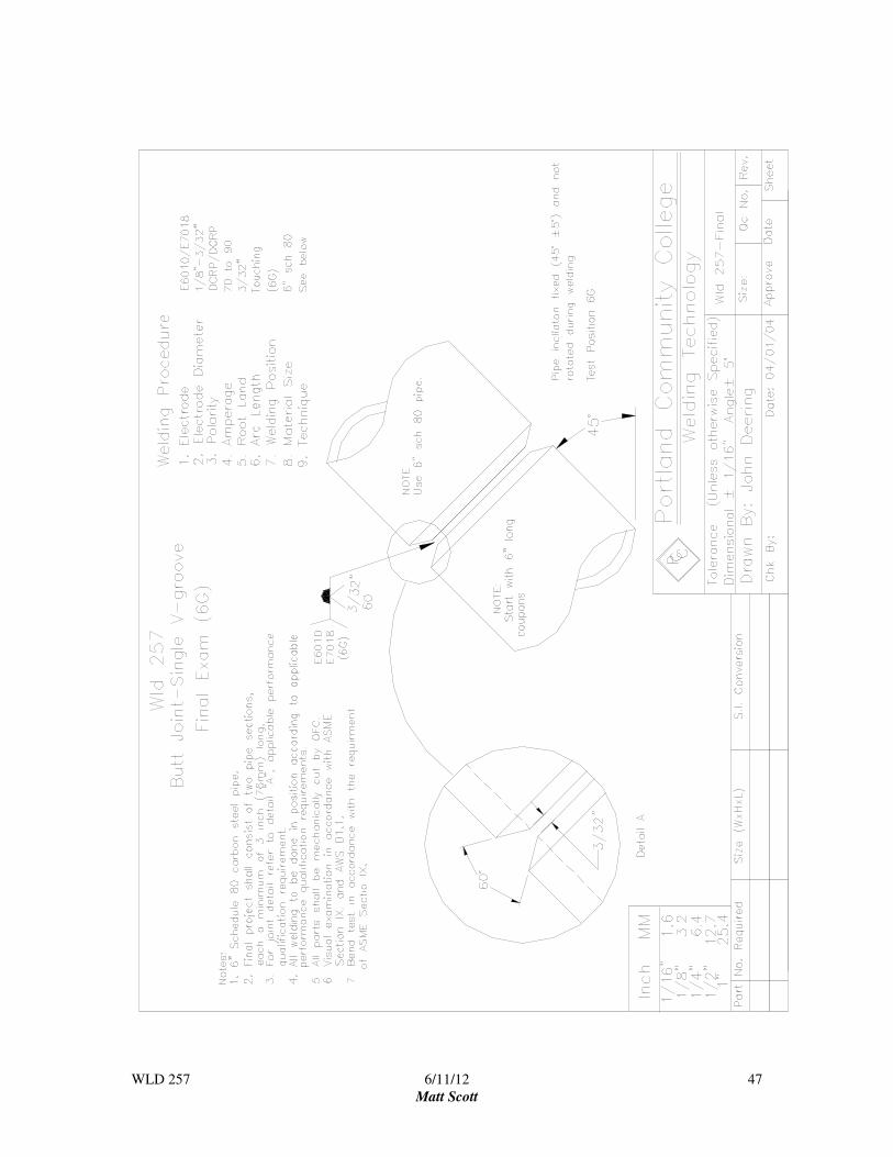
Part Two
This portion of the exam is a practical test where you will fabricate and weld a weldment
from a blue print. The evaluation of this portion of the exam will be based on quality.
Once completed, return the print with the weldment to the instructor for grading.
WLD 257 6/11/12
Matt Scott
46
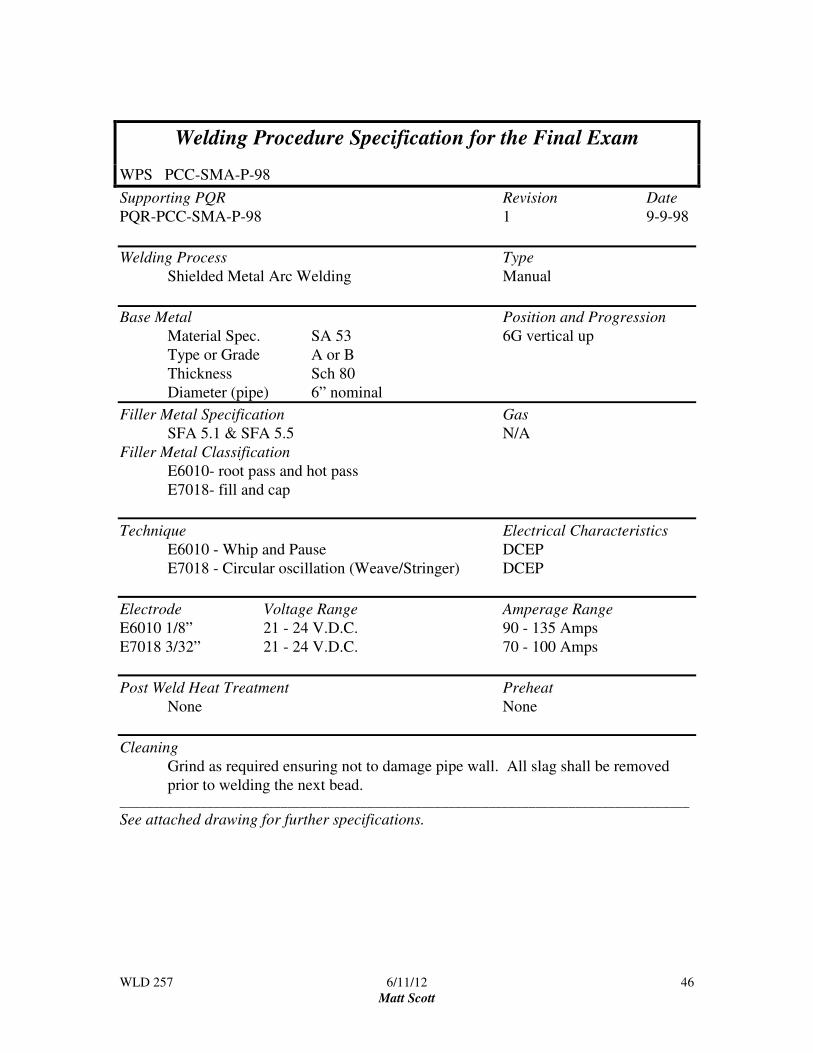
Welding Procedure Specification for the Final Exam
WPS PCC-SMA-P-98
Supporting PQR Revision Date
PQR-PCC-SMA-P-98 1 9-9-98
Welding Process Type
Shielded Metal Arc Welding Manual
Base Metal Position and Progression
Material Spec. SA 53 6G vertical up
Type or Grade A or B
Thickness Sch 80
Diameter (pipe) 6” nominal
Filler Metal Specification Gas
SFA 5.1 & SFA 5.5 N/A
Filler Metal Classification
E6010- root pass and hot pass
E7018- fill and cap
Technique Electrical Characteristics
E6010 - Whip and Pause DCEP
E7018 - Circular oscillation (Weave/Stringer) DCEP
Electrode Voltage Range Amperage Range
E6010 1/8” 21 - 24 V.D.C. 90 - 135 Amps
E7018 3/32” 21 - 24 V.D.C. 70 - 100 Amps
Post Weld Heat Treatment Preheat
None None
Cleaning
Grind as required ensuring not to damage pipe wall. All slag shall be removed
prior to welding the next bead. _____________________________________________________________________________________
See attached drawing for further specifications.
WLD 257 6/11/12
Matt Scott
47
WLD 257 6/11/12
Matt Scott
48
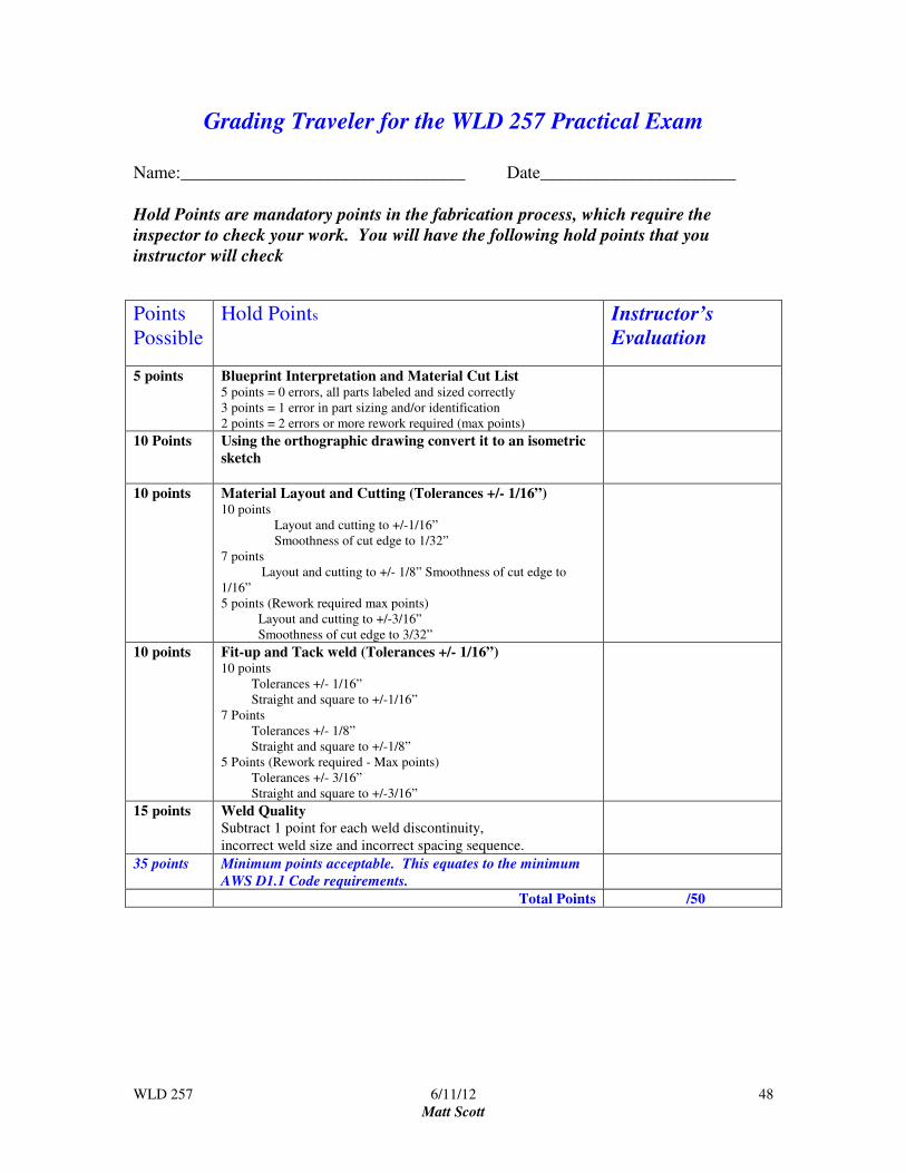
Grading Traveler for the WLD 257 Practical Exam
Name:________________________________ Date______________________
Hold Points are mandatory points in the fabrication process, which require the
inspector to check your work. You will have the following hold points that you
instructor will check
Points
Possible
Hold Points Instructor’s
Evaluation
5 points Blueprint Interpretation and Material Cut List 5 points = 0 errors, all parts labeled and sized correctly
3 points = 1 error in part sizing and/or identification
2 points = 2 errors or more rework required (max points)
10 Points Using the orthographic drawing convert it to an isometric
sketch
10 points Material Layout and Cutting (Tolerances +/- 1/16”) 10 points
Layout and cutting to +/-1/16”
Smoothness of cut edge to 1/32”
7 points
Layout and cutting to +/- 1/8” Smoothness of cut edge to
1/16”
5 points (Rework required max points)
Layout and cutting to +/-3/16”
Smoothness of cut edge to 3/32”
10 points Fit-up and Tack weld (Tolerances +/- 1/16”) 10 points
Tolerances +/- 1/16”
Straight and square to +/-1/16”
7 Points
Tolerances +/- 1/8”
Straight and square to +/-1/8”
5 Points (Rework required - Max points)
Tolerances +/- 3/16”
Straight and square to +/-3/16”
15 points Weld Quality
Subtract 1 point for each weld discontinuity,
incorrect weld size and incorrect spacing sequence.
35 points Minimum points acceptable. This equates to the minimum
AWS D1.1 Code requirements.
Total Points /50

WLD 257 6/11/12
Matt Scott
49
WLD 257 Isometric Drawing
Name: ________________________________ Date: __________________

WLD 257 6/11/12
Matt Scott
50
Final Grades - WLD 257 Name: _________________ Instructor: ___________________ Date: __________________
Welding Projects = 40%
Out of Out of Out of
Out of Out of Out of
Out of Out of Out of
Out of Out of Out of
Out of Out of Out of
Out of Out of Out of
A Total Project pts. ________ / Total pts. Possible _______ X 40 = _______ %
Written Work = 20%
Out of Out of Out of
Out of Out of Out of
Out of Out of Out of
B. Total Project pts. ________ / Total pts. Possible _______ X 20 = _______ %
Safety = 15% Each day of attendance is worth 3 points earned. Any safety violation will result in 0 points
for the day.
Out of Out of Out of Out of Out of Out of
Out of Out of Out of Out of Out of Out of
Out of Out of Out of Out of Out of Out of
C Total pts. earned ________ / Total pts. Possible _______ X 15 = _______ %
Employability Skills = 15% The following attributes will be assessed - attendance, attitude, time
management, team work, interpersonal skills, etc.. Daily points (there are no excused absences, hence no
points earned for days missed ) 3 pts = present and working for the entire shift; 2 pts = late; 1 pt = late and
left early; 0 pts = no show.
Out of Out of Out of Out of Out of Out of
Out of Out of Out of Out of Out of Out of
Out of Out of Out of Out of Out of Out of
D Total pts. earned ________ / Total pts. Possible _______ X 15 = _______ %
Final Exam 10%
Written Exam Out of
Practical Exam Out of
E Total Project pts. ________ / Total pts. Possible _______ X 10 = _______ %
Add Lines A + B + C + D +E. This will give you your Final Grade TOTAL % _________
FINAL GRADE _________