wl low voltage metal ... · wl low voltage metal-enclosed switchgear selection and application...
TRANSCRIPT

usa.siemens.com/switchgear
WL Low Voltage Metal-Enclosed SwitchgearSelection and Application Guide


Type WL Low Voltage Metal-Enclosed Switchgear
1
Table of Contents
General Information 2
Construction Details 3 - 5
WL Circuit Breaker 6
Electronic Trip Unit 7 - 9
Time / Current Characteristic Curves 10 -12
Breaker Technical Data 13 - 21
WL Secondary Terminal Assisgnments 22
WL Communication Overview 23
Section Configurations 24 - 25
Shipping Weights and Dimensional Information 26 - 30
VT, CPT, CT Data 31
Guide Form Specifications 32 - 36

Type WL Low Voltage Metal-Enclosed Switchgear
2
General Information
Siemens Type WL low voltage metal-enclosed switchgear is designed, constructed and tested to provide superior power distribution, power monitoring and control. At the heart of the Type WL low voltage switchgear is the World Class Siemens WL breaker.
Siemens Type WL low voltage switchgear can be utilized in the following applications: • Industrial Heavy assembly Semiconductor Petrochemical Automotive Biotech Pharmaceutical
• Institutional Water treatment Airports Universities Medical facilities Correctional facilities
• Critical Power Data Processing Continuous industrial process Hospitals
• Utility and co-generation
• Commercial Large office buildings Distribution centers Large warehouses
Product Scope: • Equipment ratings 635VAC Maximum 3 Phase 3 Wire, 3 Phase 4 Wire 50/60 Hz 6000 amp maximum horizontal bus 6000 amp maximum vertical bus
• Enclosure options NEMA 1 Indoor NEMA 3R Outdoor Walk-In NEMA 3R Outdoor Non Walk-in
Siemens WL breakers can be manually or electrically operated, fused or unfused and are available in the following rating designations – N, S, H, L, M and F. Refer to tables on Page 13 for interrupt and withstand ratings for each rating designation.
Industry StandardsType WL switchgear with power circuitbreakers are designed, tested andconstructed in accordance with:• UL 1558 – Metal-Enclosed Low Voltage Power Circuit Breaker Switchgear• ANSI C37.20.1 – Metal-Enclosed Low Voltage Power Circuit Breaker Switchgear• ANSI C37.50 – Test Procedure for Low Voltage AC Power Circuit Breakers Used in Enclosures• ANSI C37.51 – Conformance Testing of Metal-Enclosed Low Voltage AC Power Circuit Breaker Switchgear Assemblies• NEMA SG5 - Power Switchgear Assemblies• Applicable requirements of the National Electric Code (NEC)
WL drawout circuit breakers are inaccordance with:• UL 1066 – Low Voltage AC and DC Power Circuit Breakers Used in Enclosures• ANSI C37.13 – Low Voltage AC Power Circuit Breakers Used in Enclosures• ANSI C37.16 – Preferred Ratings, Related Requirements, and Application for Low Voltage Power Circuit Breakers and AC Power Circuit Protector
• ANSI C37.17 – Trip Devices for AC and General Purpose DC Low-Voltage Power Circuit Breakers• NEMA SG3 - Low Voltage Power Circuit Breakers
Features and modifications required by NEC are incorporated when the assemblyis designated as “Service Equipment.”
UL Listing Underwriters’ Laboratories listing mark (UL) is supplied for each vertical section provided all devices within a vertical section are UL Listed or UL Recognized and suitable for the intended use. All circuit breaker drawout elements are UL Listed.
Optional CSA compliance with cULlabeling is available.
Arc ResistantOptional Type WL arc resistant low voltage switchgear is available and is ULlisted to ANSI/IEEE C37.20.7. Type 2Barc resistant accessibility rating withmaximum internal arcing short-circuitcurrent rating of 100kA @508V and85kA @ 635V.
Seismic QualificationSeismic qualification to all major seismicconstruction standards (IBC, UBC, CBC,SBC, BOCA and IEEE 693) is available.
Type WL Low Voltage Metal-Enclosed Switchgear

Type WL Low Voltage Metal-Enclosed Switchgear
3
Construction Details
GeneralThe Siemens Type WL switchgear assembly consists of one or more metal-enclosed vertical sections. The end sections are designed to allowinstallation of future sections.
Each vertical section consists of up to four individually enclosed breaker or auxiliary compartments which are sized to provide uniform height.
Included in each assembly are various components such as circuit breakers, instrumentation and control equipment, transformers, relays, three-phase bus work, and all internal wiring, connectors, and other supporting equipment.
In accordance with ANSI C37.20.1, the maximum temperature for parts that are handled is 50°C. The main bus maximum temperature rise is 65°Cabove 40°C ambient. The temperaturerise of the air surrounding the cableconnection points is limited to 45°Cabove 40°C ambient.
Finish During construction, the structural steel parts, panels, and compartments are all prepared for painting by a five-stage wash system.
Standard finish color is light gray ANSI61. The standard painting process is aUL approved electrostatic powder coatpaint system utilizing a polyester powdercoat paint. The completed finish hasa nominal 2 mils dry film thickness.
Assembly ConstructionSiemens Type WL metal-enclosed lowvoltage switchgear is constructed ofa rigid internal frame structure thatminimizes the possibility of damageduring shipment and supports multipleinstallation methods – rolling or lifting.Lifting eyes are integrated into theinternal frame design and ensurethe structural integrity of the liftingassembly is always adequate for theweight of the total structure.
If requested in advance, the switchgearstructure can be shipped so that theunit can be tilted onto its back duringinstallation. This is an option that mustbe specified at order entry.
Each complete vertical section containsthree compartments.(1) Front compartment containing breakers and/or auxiliary equipment(2) Bus compartment containing horizontal and vertical bus(3) Rear cable compartment containing the load side runbacks connecting the load side of the breaker to the load cable terminals
Within the front compartment, eachbreaker is barriered and compartmentedfrom all other breakers in the frontcompartment. This design also isolatesthe breakers in the front compartmentfrom the bus compartment.
Optional barriers can be supplied toisolate the bus compartment from therear cable compartment. Other optionalbarriers include: (1) Full depth sectionbarriers to isolate one section from theadjacent section(s). (2) Barriers to isolatethe incoming line side connections to the main breaker(s) from the load side bus and connections in the switchgear section. (Line/load barriers are provided as a standard feature for service equipment main breakers.)
1. Breaker Hoist and Track2. Ventilation and Lifting Structure3. Quarter Turn Door Latch4. Secondary Disconnect Access Door5. Channel Sill Base (Optional)6. Breaker Compartment7. Auxiliary Instrument Compartment8. Secondary Disconnect9. Breaker Cradle (Guide Frame)10. Breaker Drawout Rail11. TOC Switch Operator
11
1
7
6
2
3
4
5
8
9
10

Type WL Low Voltage Metal-Enclosed Switchgear
4
Construction Details
Main and Ground Bus The standard main bus is silver-plated-copper. Tin-plated copper bus is optionally available. Vertical and horizontal bus bar utilize a channel shape design to maximize short circuit withstand capability and minimize heat rise. All bus joints include Grade 5 bolts and conical spring washers. Provisions for future extension of the main bus include plated joints and high tensile strength steel hardware.
The main three-phase horizontal busis arranged vertically one phase abovethe other with edge-to-edge alignmentto provide high, short circuit strength.Insulated main bus with isolated verticalbus is optional.
Vertical bus ratings available are 1600,2000, 3200, 4000, 5000 and 6000amperes continuous current. Horizontalbus ratings available are 1600, 2000,3200, 4000, 5000 and 6000 amperes.A neutral bus is furnished whenspecified, and can be rated 1600,2000, 3200, 4000, 5000 or 6000amperes continuous current.
A 1/4” X 3” standard copper ground busextends through all sections. Cable lugsare mounted to the ground bus ineach section.
Standard short-circuit withstand (4 cycle)and short-time withstand (60 cycle) busbracing is 100,000 amperes. Higher shortcircuit withstand bus bracings (150kA and 200kA) are available.
Load side runbacks for feeder circuitsare copper construction, are insulatedwith sleeve tubing in the main bus area,and are supported by high-strengthbus bracing.
Control and Communication WiringStandard control and communicationwiring is #14 AWG extra-flexible, stranded copper type SIS. Control andcommunication wiring is installed andaccessed from the front of the switchgearstructure. Each breaker compartment has a dedicated horizontal and vertical wireway.
For devices not having screw-typeterminals, pressure terminals are used.
Insulation The insulation used is a UL recognized thermoset material that has excellent heat resistance, flame retardance, dimensional stability and low moisture absorption.
Circuit Breaker CompartmentsTypical circuit breaker compartmentsinclude primary disconnects, drawoutrails, secondary disconnects, verticalwireway, horizontal wireway and,if applicable, TOC switch operator,MOC switch operator and associatedinterlocks. Draw-out rails allow thebreaker to be withdrawn from thecompartment without additionalextensions or adapters. Up to six (2sets of three) current transformers formetering or relaying can be mountedin each compartment.
A variety of auxiliary devices such asbreaker control switches, indicatinglights and pushbuttons can be mountedon the breaker compartment door.
1. TOC Switch Operator 2. Breaker Compartment Rear Barrier 3. Secondary Disconnect 4. Vertical Wireway
5. Interference Interlock 6. Drawout Rails 7. Primary Disconnect 8. Cradle Mounted Current Transformer
Circuit breaker cell interior
1
5 6 7 8
2 3 4

Type WL Low Voltage Metal-Enclosed Switchgear
5
Construction Details
Options
Switchgear Mounted Hoist The integrally mounted hoist, standard on walk-in outdoor and optional on indoor switchgear enclosures, travels along rails on top of the switchgear to assist in breaker handling. TOC and MOC Switches The Truck Operated Cell (TOC) Switch provides interlocking control or remote indication of the breaker racking position. The cubicle mounted auxiliary switch or Mechanism Operated Cell (MOC) switch provides interlocking control or remote indication based on the main contact position (open or closed).
ShuttersThese provide protection against accidental contact with primary disconnects in a compartment when the breaker is removed. Shutters automatically close when the breaker is withdrawn and are pad-lockable and field installable.
Key InterlockThis provides a mechanical means foroperating circuit breakers and otherdevices only when predescribedconditions are met.
Test SetA portable breaker test set is available asan option and supports testing the fullrange of functions and protective settingssupplied with the breaker trip unit.
Metering and Auxiliary CompartmentsCompartments are available to housedevices such as voltage transformers,metering, control power transformers,and supervisory devices.
Instrument and Control TransformersVoltage transformers and control powertransformers are mounted in auxiliarycompartments. These transformersare protected by primary pull-out typecurrent-limiting fuses and secondaryfuses. Current transformers are normallymounted on the compartment primarydisconnect studs where they are readilyaccessible. See Tables on Page 31 foravailable ratings.
Miscellaneous• Each switchgear lineup includes a breaker lifting device that is adjustable for use with Size II and Size III breakers.• An optional portable breaker hoist is available if the integrated breaker hoist and track is not specified.• A test cabinet is also available as an option. The test cabinet is wall mounted necessary equipment for testing electrically-operated breakers that have been removed from the breaker compartment. The test cabinet doesn’t include or replace a breaker trip unit tester.• A WL remote breaker racking device (RBRD) is available as an optional accessory that allows maintenance personnel to safely rack Siemens Type WL breakers into the Connect, Test and Disconnect positions from up to 30 feet away from the breaker. This allows the operator to be outside the arc flash hazard boundary and thereby providing additional personnel protection.• 4” high formed steel channel sills are available for indoor switchgear enclosures.
Outdoor SwitchgearType WL switchgear is available in twooutdoor (NEMA 3R) enclosures. Walk-inand non walk-in versions are availableto meet your particular application.
For protection from snow, rain and otherforeign matter, both outdoor enclosuresrest on a six-inch high, formed steel basewhich provides rigid support and a tightbottom seal. A heavy duty protectiveunder-coating is applied to the undersideof all outdoor enclosures to protectagainst moisture and corrosion. Shieldedventilation housings permit proper aircirculation while excluding dirt andforeign matter. In the walk-in outdoor enclosure a light-ed, unobstructed service aisle is provided at the front of the switchgear allowing inspection and maintenance without exposure to the elements. An access door equipped with an emergency bar release is located at each end of the aisle.
The following features are standardwith walk-in outdoor enclosures.(1) Space heaters in breaker compartment and bus compartment.(2) Screens and filters for exterior door ventilation louvers.(3) Incandescent lighting receptacle with three-way switch at each aisle access door.(4) Duplex receptacle with ground fault protection at each aisle access door.(5) Load center for power distribution to lights, receptacles, switches and heaters. For non walk-in outdoor enclosures,space heaters and screens/filters forventilation louvering are standard withlighting, receptacles, switches and loadcenters offered as options.
Side view
Rear view

Type WL Low Voltage Metal-Enclosed Switchgear
6
WL Circuit Breaker
WL Circuit Breaker: Superior individual products for low-voltage power distribution systems
1. Guide Frame
2. Vertical to Horizontal BUS Connector
3. Position Signaling Switch (TOC)
4. Breaker / Guide Frame Grounding Contact
5. Shutter (locking)
6. MODBUS or PROFIBUS Communications
7. External CubicleBUS I/O Module
8. Plug-In Open and Closed Solenoids
9. Multiple Secondary Connections
10. Auxiliary Switch Block
11. Door Sealing Frame
12. Interlocking Set Base Plate
13. Protective Cover for OPEN/CLOSE Buttons
14. Multiple Key Locking Accessories
15. Single Bolt Motor Operator Installation
16. Operations Counter
17. Breaker Status Sensor (BSS)
18. Complete Trip Unit Family
19. Remote Reset
20. Breaker Data Adapter (BDA) for Internet Connection
21. Multi Angle LCD Module
22. Ground Fault Protection Module
23. Rating Plug
24 . Metering Function (+ wave forms and harmonics)
25. Circuit Breaker
5
6 7
8
9
11
12
1315
16
17
20
21
22
23
24
19
18
25
14
10
2
3
4

Type WL Low Voltage Metal-Enclosed Switchgear
7
Electronic Trip Unit
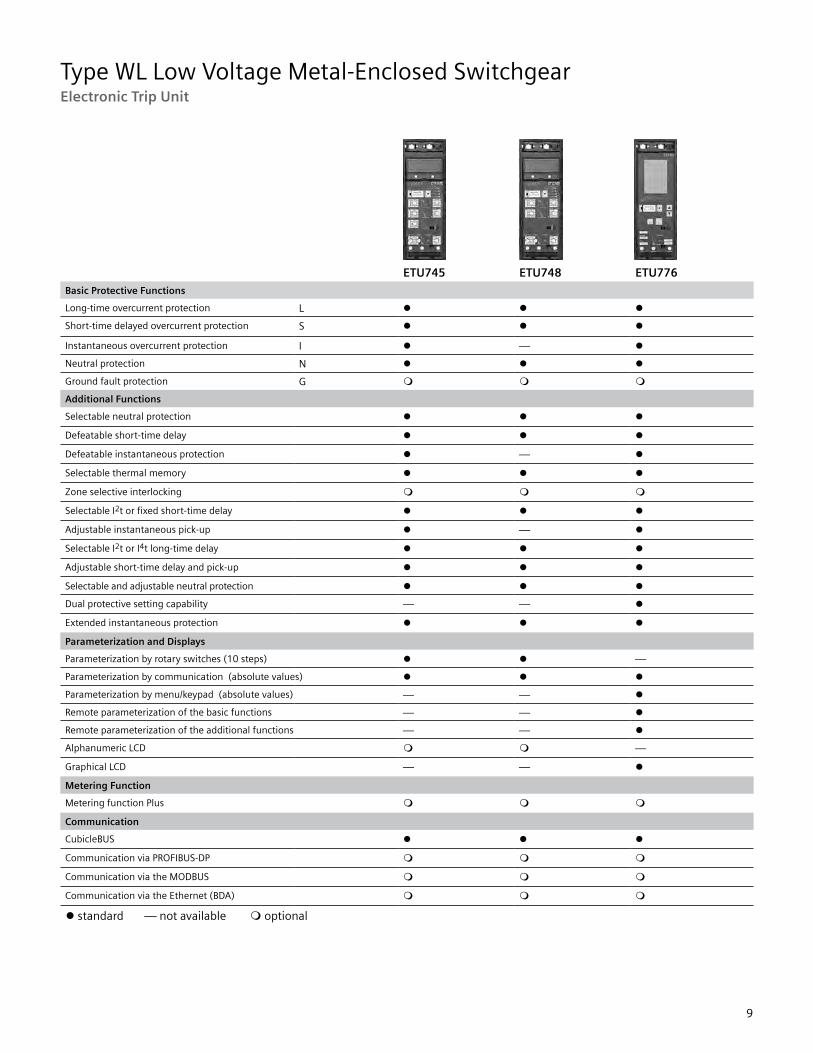
Electronic Trip Unit During development of our electronic trip units we have consistently striven to ensure modularity. The following are just some of the modules that are simple to retrofit at any time: • Ground fault protection • Communication • Metering function • Displays • Rating plugs
This enables fast local adaptation tonew system conditions. At the sametime, the ETUs are provided with new,innovative functions, and all tripunits are completely interchangeableindependent of breaker ratings.
Rating Plug The Rating Plug is a replaceable module that enables users to reduce the rated device current for optimum adaptation to the system; e.g. during startup of a plant section. The Rating Plug should be selected so that it corresponds to the rated current of the system.
Switch-selectable I2t or I4t Characteristic Curve Improved Overload Protection The best possible protection is assured when all protective devices in the system are optimally coordinated. To achieve optimum selectivity and coordination, the long-time characteristic can be switched between l2t and l4t.
Switchable Parameter Sets To allow the protection to adapt tochanges in system needs such asswitching between utility and generatorfeeds, WL Circuit Breakers supportETUs with two independent parametersets. Switching between the parametersets occurs in less than 100 ms and canbe done remotely or via a contact inputto an optional CubicleBUS module.
Extended Instantaneous ProtectionThe electronic trip units designed for use with the WL circuit breaker provide a feature we call “Extended Instantaneous Protection” (Patent Pending).
It allows the WL breaker, as a family,across the entire range of ampacitiesto be applied at the withstandrating of the breaker with minus 0%tolerance; that means no instantaneousoverride. EIP further enables the circuitbreaker to be applied up to the fullinterrupting rating of the breaker onsystems where the available faultcurrent exceeds the withstand rating,even with LS-only trip units. Why isthis feature important? The answeris reliable power.
The coordination of the main breakerand the first level of feeder breakersis especially important because of thewide spread outage that will occur ifone of these breakers trips unnecessarily.
Conventional practice is to specifyelectronic trip beakers with “LS” typetrip units in critical power systems.These ‘Long-Time’ and ‘Short-Time’only trip units forgo the fast trippingtimes given by an ‘Instantaneous’ function. The justification for this delay is the benefit of allowing a downstreambreaker to open first to clear a highmagnitude fault. The main or feederstays closed to keep the remainder ofthe loads operating.
However, a circuit breaker with anLS-only trip unit may never be appliedon a system capable of delivering faultcurrent higher than the breaker’s withstand rating, commonly 85kA or less. Where the available fault current is above this level, a breaker with an additional function must be used – an instantaneous override. This instantaneous override function trips the breaker instantly when the fault current reaches a pre-determined level below the withstand rating, usually around 20% lower. The benefit of this override is to allow application of the breaker up to the interrupting rating, which may be as high as 150kA. The disadvantage is that it compromises the coordination benefit because the main will probably trip at the same time asa downstream branch breaker in that 20% lower override window.
This is where the Extended Instantaneous Protection feature of the WL can offer the level of coordination and protectionfunctionality. Unlike an instantaneousoverride, Extended InstantaneousProtection (EIP) allows the full withstand rating – in fact up to the tolerance of plus 20% higher. Of course, EIP still provides the ability of the breaker to be applied at the interrupting level, as high as 150kAin a Frame Size III, non-fused breaker.This unique combination enables the system designer to achieve thehighest possible level of coordinationin the industry and also allowsapplication of the WL on modernpower systems with extremely highlevels of available fault current.
A further benefit offered by EIP, over a standard LS trip unit equipped breaker, is that it provides an extra measure of protection in the event that the available fault current increases at some time during the life of the system beyond the withstand level. This would typically be due to a utility transformer change but could also be due to the addition of generators or large motors that contribute fault current. EIP provides the breaker the ability to react in an instantaneous fashion to a high level fault instead of having to rely on the slower reaction time of the short-time function.
Sample Configuration of an ETU745Manual Trip Indicator with optional remote RESET
Rating plug
Ground Fault Protection Module (field installable)
LCD display with adjustable- angle viewing
Micro switches for switch selectable characteristic curve adjustments

Type WL Low Voltage Metal-Enclosed Switchgear
8
Electronic Trip Unit
Selection Criteria for WL Circuit BreakersThe basic criteria for selecting circuitbreakers is:
Maximum Available Short Circuitat the installation point. This valuedetermines the short circuit currentinterrupting rating or short circuit currentwithstand rating of the circuit breaker.
Rated Current In which is to flowthrough the respective circuit breakercontinuously. This value may not be greater than the maximum rated current of the circuit breaker. The rated current for the WL is determined by the rating plug, up to the maximum frame rating.
Ambient Temperature of thecircuit breaker.
Design of the circuit breaker.
Protective Functions of the circuitbreaker. These are determined by theselection of the appropriate trip unit.
Dynamic Arc-Flash Sentry (PatentPending) A unique feature of the WLtrip unit allows the system designer toachieve lower levels of arc flash energyand delayed tripping for selective tripcoordination purposes.
Dynamic Arc-Flash Sentry (DAS) employsthe unique dual protective settingcapability of the 776 trip units, coupledwith the ability to easily toggle to a lower arc flash parameter set. A normal operation parameter set can be optimized for selective trip coordination, while the second set is optimized for lower arcflash energy levels. The dynamic actioncomes from the ability to switch fromthe normal operation set to the arc flashlimiting set based on the presence ofpersonnel as they approach the flashprotection boundary. A wide variety ofswitching methods may used based onthe needs of a particular facility. Thecapabilities range from fully automaticswitching using appropriate occupancysensors to manual switching via akey operation.
Type WL Low Voltage Metal-Enclosed Switchgear
9
Electronic Trip Unit
ETU745 ETU748 ETU776
Basic Protective Functions
Long-time overcurrent protection L l l l
Short-time delayed overcurrent protection S l l l
Instantaneous overcurrent protection I l — l
Neutral protection N l l l
Ground fault protection G m m m
Additional Functions
Selectable neutral protection l l l
Defeatable short-time delay l l l
Defeatable instantaneous protection l — l
Selectable thermal memory l l l
Zone selective interlocking m m m
Selectable I2t or fixed short-time delay l l l
Adjustable instantaneous pick-up l — l
Selectable I2t or I4t long-time delay l l l
Adjustable short-time delay and pick-up l l l
Selectable and adjustable neutral protection l l l
Dual protective setting capability — — l
Extended instantaneous protection l l l
Parameterization and Displays
Parameterization by rotary switches (10 steps) l l —
Parameterization by communication (absolute values) l l l
Parameterization by menu/keypad (absolute values) — — l
Remote parameterization of the basic functions — — l
Remote parameterization of the additional functions — — l
Alphanumeric LCD m m —
Graphical LCD — — l
Metering Function
Metering function Plus m m m
Communication
CubicleBUS l l l
Communication via PROFIBUS-DP m m m
Communication via the MODBUS m m m
Communication via the Ethernet (BDA) m m m
l standard — not available m optional
Type WL Low Voltage Metal-Enclosed Switchgear
10
Time/Current Characteristic Curves
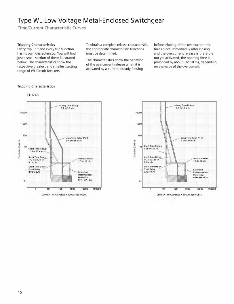
Tripping Characteristics Every trip unit and every trip function has its own characteristic. You will find just a small section of these illustrated below. The characteristics show the respective greatest and smallest setting range of WL Circuit Breakers.
To obtain a complete release characteristic, the appropriate characteristic functions must be determined.
The characteristics show the behavior of the overcurrent release when it is activated by a current already flowing
before tripping. If the overcurrent trip takes place immediately after closing and the overcurrent release is therefore not yet activated, the opening time is prolonged by about 3 to 10 ms, depending on the value of the overcurrent.
Tripping Characteristics
ETU745

Type WL Low Voltage Metal-Enclosed Switchgear
11
Time/Current Characteristic Curves
Tripping Characteristics
ETU748
Type WL Low Voltage Metal-Enclosed Switchgear
12
Time/Current Characteristic Curves
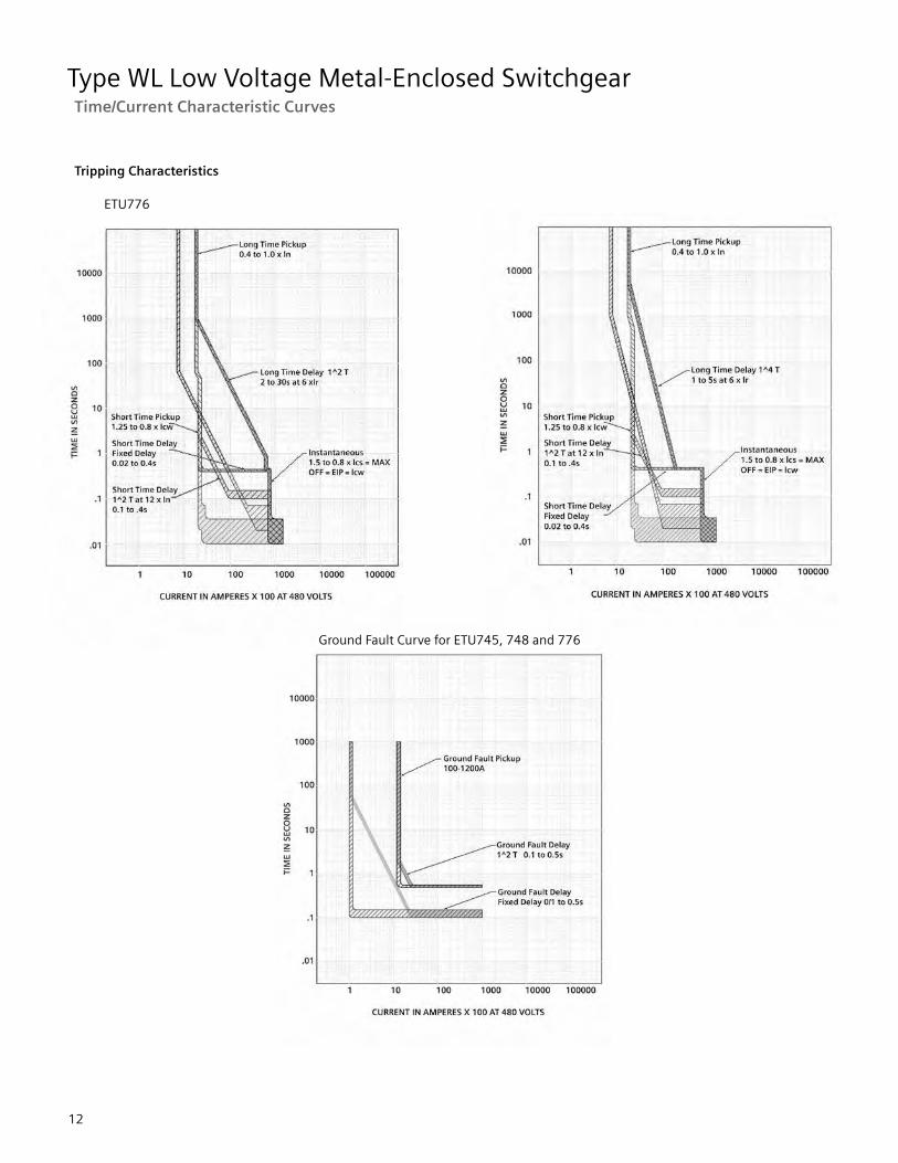
Tripping Characteristics
ETU776
Ground Fault Curve for ETU745, 748 and 776

Type WL Low Voltage Metal-Enclosed Switchgear
13
Breaker Technical Data
WL Circuit Breakers ANSI / UL 1066
Breaker Ratings
Frame Size II
800 1600 2000 3200
Frame Rating Class N S H L F N S H L F S H L F S H L
Instantaneous Short-circuit Current1 (kA RMS) 50/60 Hz
254VAC 50 65 85 100 200 50 65 85 100 200 65 85 100 200 65 85 100
508VAC 50 65 85 100 200 50 65 85 100 200 65 85 100 200 65 85 100
635VAC 50 65 65 85 200 50 65 65 85 200 65 65 85 200 65 65 85
Short-time Withstand Current Icw(kA RMS) 50/60 Hz
0.5s 50 65 65 85 — 50 65 65 85 — 65 65 85 — 65 65 85
Extended Instantaneous Protection (kA RMS -0% to +20%)
50 65 65 85 — 50 65 65 85 — 65 65 85 — 65 65 85
Close and Latch Ratings(kA RMS) 50/60 Hz
50 65 65 85 65 50 65 65 85 65 65 65 85 65 65 65 85
Rating Plug Range 200, 225, 250, 300, 315, 350, 400, 450, 500, 600, 630, 700, 800 amps
200, 225, 250, 300, 315, 350, 400, 450, 500, 600, 630, 700, 800, 1000, 1200, 1250, 1600 amps
200, 225, 250, 300, 315, 350, 400, 450, 500, 600, 630, 700, 800, 1000, 1200, 1250, 1600, 2000 amps
200, 225, 250, 300, 315, 350, 400, 450, 500, 600, 630, 700, 800, 1000, 1200,1250, 1600, 2000, 2500, 3000, 3200 amps
Endurance Rating(switching operations with maintenance) 2
Mechanical 15,000 15,000 15,000 15,000
Electrical 15,000 15,000 15,000 15,000
Frame Size III
3200 4000 5000 6000
Frame Rating Class M F H L M F H L M F H L M
Instantaneous Short circuit Current1 (kA RMS) 50/60 Hz
254VAC 150 200 85 100 150 200 85 100 150 200 85 100 150
508VAC 150 200 85 100 150 200 85 100 150 200 85 100 150
635VAC 85 200 85 85 85 200 85 85 85 200 85 85 85
Short-time Withstand Current Icw(kA RMS) 50/60 Hz
0.5s 1002 — 85 1003 1002 — 85 100 1003 — 85 100 1003
Extended Instantaneous Protection (kA RMS -0% to +20%)
254V AC
508V AC 150 150 150
635V AC 85 — 85 100 85 — 85 100 85 — 85 100 85
Close and Latch Ratings(kA RMS) 50/60 Hz
1002 85 85 85 1002 85 85 85 1002 85 85 85 1002
Rating Plug Range 800, 1000, 1200, 1250, 1600, 2000,2500, 3000, 3200 amps
800, 1000, 1200, 1250,1600, 2000, 2500, 3000,3200, 4000 amps
800,1000, 1200, 1250, 1600, 2000 2500, 3000, 3200, 4000, 5000 amps
800,1000, 1200, 1250, 1600, 2000 2500, 3000, 3200, 4000, 5000, 6000 amps
Endurance Rating(switching operations with maintenance) 2
Mechanical 10,000 10,000 10,000 10,000
Electrical 10,000 10,000 10,000 10,000
1 Maximum rated voltage for fused breakers is 600VAC. 2 Maintenance means: replacing main contacts and arc chutes (see operating instructions). 3 Short-time withstand rating is 85kA RMS at 635VAC.

Type WL Low Voltage Metal-Enclosed Switchgear
14
Breaker Technical Data
WL Non-Automatic Switches ANSI / UL 1066
WL Circuit Breakers
Frame Size II Frame Size III
800 1600 2000 3200 3200 4000 5000 6000
Frame Rating Class L F1 L F1 L F1 F1 L L F1 L F1 L
Short-time Withstand Current (kA RMS) 50/60 Hz
0.5s 85 20 85 20 85 20 85 40 100 40 100 40 100
Breaking Capacity withExternal Relay (kA RMS)635Vac , 50/60 Hz,max time delay
0.5s 85 20 85 20 85 20 85 40 100 40 100 40 100
Frame Size II Frame Size III
Frame Rating 800 1600 2000 3200 3200 4000 5000 6000
Rated current Inat 40°C, at 50/60Hz
A 800 1600 2000 3200 3200 4000 5000 6000
Rated operational(nominal) voltage
V AC 600 600 600 600 600 600 600 600
Rated maximum voltage V AC 635 635 635 635 635 635 635 635
Permissible ambienttemperature operation(for operation withLCD max. 55°C)
ºC -25 / + 70 -25 / + 70 -25 / + 70 -25 / + 70 -25 / + 70 -25 / + 70 -25 / + 70 -25 / + 70
Storage(observe special conditions for LCD)
ºC -40 / +70 -40 / +70 -40 / +70 -40 / +70 -40 / +70 -40 / +70 -40 / +70 -40 / +70
Power loss at Rated Currentwith 3-phase 2 symmetrical load
W85 130 (fused)
320 520 (fused)
500850(fused)
1150 700 1100 1650 2475
Operating timesMake-time
ms 35 35 35 35 35 35 35 35
Break-time (with active ETU) 3 ms 34 34 34 34 34 34 34 34
Break-time (without active ETU) 4 ms 50 50 50 50 50 50 50 50
Total clearing time (with active ETU) 3 ms 50 50 50 50 50 50 50 50
Total clearing time (without active ETU) 4 ms 65 65 65 65 65 65 65 65
Make-time, electrical (via closing solenoid)
ms 50 50 50 50 50 50 50 50
Break-time, electrical(via shunt trip)
ms 40 40 40 40 40 40 40 40
(via instantaneous UVR) ms 73 73 73 73 73 73 73 73
1 Interrupting rating is equal to 200kA based on the rating of the fuse. 2 Consult factory for fuse carriage power loss. 3 ETU with external control power. 4 ETU without external control power.

Type WL Low Voltage Metal-Enclosed Switchgear
15
Breaker Technical Data
WL Circuit Breakers
Frame Size II Frame Size III
Frame Rating 800 1600 2000 3200 3200 4000 5000 6000
EnduranceMechanical (without maintenance)
Operatingcycles
12,500 12,500 10,000 10,000 5,000 5,000 5,000 5,000
Mechanical (with maintenance) 1
Operatingcycles
15,000 15,000 15,000 15,000 10,000 10,000 10,000 10,000
Electrical (without maintenance) 1
Operatingcycles
7,500 7,500 4,000 4,000 2,000 2,000 2,000 2,000
Electrical (with maintenance) 1Operatingcycles
15,000 15,000 15,000 15,000 10,000 10,000 10,000 10,000
Switching frequency 1/h 60 60 60 60 60 60 60 60
Minimum intervalbetween breaker trip and next closing of the circuit breaker (when used with the automatic mechanical reset of the bell alarm)
ms 80 80 80 80 80 80 80 80
Mounting position
Auxiliary secondary wiresize (Cu) max # of aux. connecting leads x cross section (solid or stranded)
Bare wirepressureterminal
1 x AWG 14 or 2 x AWG 16
Tension spring terminal
2 x AWG 14
Ring tongue terminal (standard)
2 x AWG 14
1 x AWG 10 2
2 x AWG 16
TOC wire connection size(Cu) max # of aux. connecting leads x cross section (solid or stranded)
Bare wirepressureterminal
1 x AWG 14
Weight 3Circuit Breaker Guide Frame kg/lb
72/159 72/159 72/159 95/209 155/341 155/341 155/341 155/341
51/112 51/112 60/132 69/152 139/306 139/306 139/306 139/306
MOC wire connectionsize (Cu) max # of aux. connecting leads x crosssection (solid or stranded)
Bare wirepressureterminal
1 x AWG 14
1 Maintenance consists of replacing main contacts and arc chutes (see operating instructions.) 2 For use only with Siemens supplied ring terminals (WL10RL). 3 Fused Breaker Weights (kg/lb) Frame Size II (fused) Frame Size III (fused)
Breaker 103/227 same as table above Guide Frame 68/150 130/275 Fuse Carriage – 102/225

Type WL Low Voltage Metal-Enclosed Switchgear
16
Breaker Technical Data
WL Circuit Breaker Accessory Ratings
Manual Operating Mechanism with Mechanical Closing
Closing/charging stored energy mechanism Maximum actuating force required on hand lever
52 lbs
Number of hand lever strokes required 9
Manual Operating Mechanism with Mechanical and Electrical Closing
Charging stored-energy mechanism
Closing solenoid Coil voltage tolerance and shunt trip
24V DC 48V DC 120V AC / 125V DC 240V AC / 250V DC
14-28V DC 28 - 56V DC 70 - 140V DC 104-127V AC 140 - 280V DC 08 - 254V AC 180Y / 104V AC 220Y / 127V AC
Power consumption (5 % duty cycle) 120 W
Minimum closing solenoid actuation signal required 50 ms
Motor Operating Mechanism with Mechanical and Electrical Closing
Spring charging motor
Motor voltage tolerance at 120V AC, 240V AC 85 - 110%
Extended tolerance for battery operation at 24V DC, 48V DC, 125V DC, 250V DC 70 - 126%
Power consumption of the motor 110 W
Time required for charging the stored-energy mechanism ≤ 10 s
Closing solenoid
For motor and closing solenoid short-circuit protection
Short-circuit protection Standard slow-blow cartridge fuse
24 - 60 V 10 - 250 V
6A 3A
Auxiliary Release
Undervoltage release (UVR) Operating values
≥ 85% (circuit breaker can be closed)
35 - 70% (circuit breaker opens)
AC Coil voltage tolerance at 120V AC, 240V AC 85 - 110%
DC Extended tolerance for battery operation at 24V DC, 48V DC, 125V DC, 250V DC 85 - 126%
Rated control supply voltage AC 50/60Hz V 120,240
DC V 24, 48, 125, 250
Power comsumption (inresh / continuous AC VA 200 / 5
DC W 200 / 5
Opening time of the circuit breaker for AC/DC ms 200
UVR (no time delay), 2 settings Setting 1 Setting
ms ms
80 200
UVR (with time delay) Adjustable delay
s
02. to 3.2
Reset by additional NC direct opening ms ≤ 100
Type WL Low Voltage Metal-Enclosed Switchgear
17
Breaker Technical Data
WL Circuit Breaker Accessory Ratings
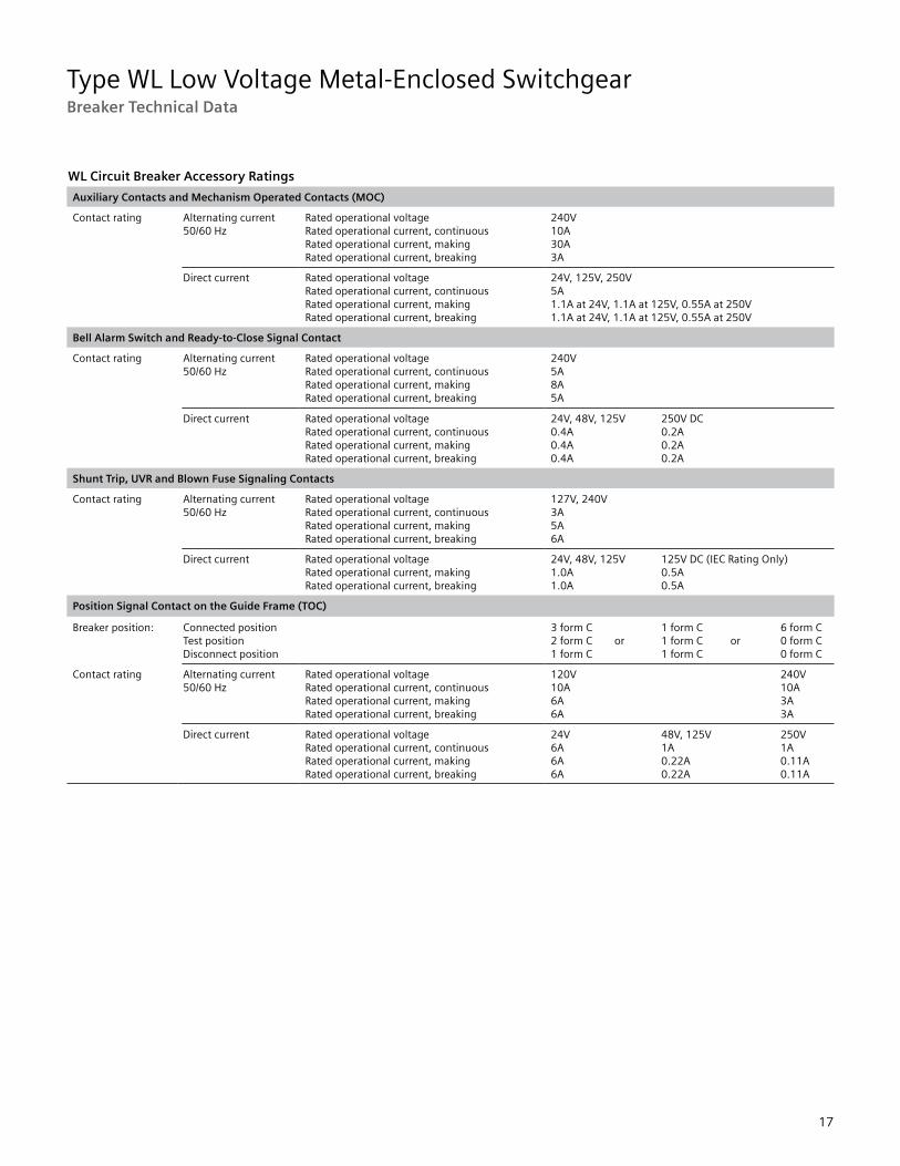
Auxiliary Contacts and Mechanism Operated Contacts (MOC)
Contact rating Alternating current 50/60 Hz
Rated operational voltage Rated operational current, continuous Rated operational current, making Rated operational current, breaking
240V 10A 30A 3A
Direct current Rated operational voltage Rated operational current, continuous Rated operational current, making Rated operational current, breaking
24V, 125V, 250V 5A 1.1A at 24V, 1.1A at 125V, 0.55A at 250V 1.1A at 24V, 1.1A at 125V, 0.55A at 250V
Bell Alarm Switch and Ready-to-Close Signal Contact
Contact rating Alternating current 50/60 Hz
Rated operational voltage Rated operational current, continuous Rated operational current, making Rated operational current, breaking
240V 5A 8A 5A
Direct current Rated operational voltage Rated operational current, continuous Rated operational current, making Rated operational current, breaking
24V, 48V, 125V 250V DC 0.4A 0.2A 0.4A 0.2A 0.4A 0.2A
Shunt Trip, UVR and Blown Fuse Signaling Contacts
Contact rating Alternating current 50/60 Hz
Rated operational voltage Rated operational current, continuous Rated operational current, making Rated operational current, breaking
127V, 240V 3A 5A 6A
Direct current Rated operational voltage Rated operational current, making Rated operational current, breaking
24V, 48V, 125V 125V DC (IEC Rating Only) 1.0A 0.5A 1.0A 0.5A
Position Signal Contact on the Guide Frame (TOC)
Breaker position: Connected position Test position Disconnect position
3 form C 1 form C 6 form C 2 form C or 1 form C or 0 form C 1 form C 1 form C 0 form C
Contact rating Alternating current 50/60 Hz
Rated operational voltage Rated operational current, continuous Rated operational current, making Rated operational current, breaking
120V 240V 10A 10A 6A 3A 6A 3A
Direct current Rated operational voltage Rated operational current, continuous Rated operational current, making Rated operational current, breaking
24V 48V, 125V 250V 6A 1A 1A 6A 0.22A 0.11A 6A 0.22A 0.11A

Type WL Low Voltage Metal-Enclosed Switchgear
18
Breaker Technical Data
Function Overview of the Electronic Trip Units
1 Extended Instantaneous Protection (EIP) allows the WL breaker to be applied at the withstand rating of the breaker with minus 0% tolerance; that means no instantaneous override whatsoever. EIP further enables the circuit breaker to be applied up to the full instantaneous rating of the breaker on systems where the available fault current exceeds the withstand rating. 2 Ground Fault Module cannot be removed after installation.
available – not available m optional

Type WL Low Voltage Metal-Enclosed Switchgear
19
Breaker Technical Data
Function Overview of the Electronic Trip Units
l
available – not available m optional

Type WL Low Voltage Metal-Enclosed Switchgear
20
Function Overview of the Electronic Trip Units
Breaker Technical Data
1 Extended Instantaneous Protection (EIP) allows the WL breaker to be applied at the withstand rating of the breaker with minus 0% tolerance; that means no instantaneous override whatsoever. EIP further enables the circuit breaker to be applied up to the full instantaneous rating of the breaker on systems where the available fault current exceeds the withstand rating. 2 Ground Fault Module cannot be removed after installation. Notes: M = Motor protection setting (20 ms) Communications = Setting the parameters of the trip unit via Breaker Adapter Module, MODBUS or PROFIBUS Keypad = Direct input at the trip unit
available – not available m optional

Type WL Low Voltage Metal-Enclosed Switchgear
21
Function Overview of the Electronic Trip Units
Breaker Technical Data
available – not available m optional

Type WL Low Voltage Metal-Enclosed Switchgear
22
WL Secondary Terminal Assignments

Type WL Low Voltage Metal-Enclosed Switchgear
23
WL Communication Overview
Features• Industry standard MODBUS or PROFIBUS communication available on all WL breakers from 200A to 6000A.• The high modularity of the WL Circuit Breakers and accessories allows simple retrofitting of all communication components.
Connection Diagram
1. Breaker Data Adapter (BDA)2. Browser-capable input and output device (e.g. notebook)3. WL Circuit Breaker4. COM 16 MODBUS module or COM 15 PROFIBUS module5. Breaker Status Sensor (BSS)6. Electronic Trip Unit7. Metering function PLUS8. Zone Selective Interlocking (ZSI) module9. Digital output module with relay or optocoupler outputs10. Digital output module with relay or optocoupler outputs, remotely configurable11. Analog output module12. Digital input module13. WinPM.Net on PC14. PLC (e.g. SIMATIC S7)15. BDA Plus components
• The ability to connect additional input and output modules to the breaker internal CubicleBUS of the WL opens up a range of opportunities to reduce secondary device count and wiring and to increase functionality implemented in switchgear.
• Innovative software products for local configuration, operation, monitoring and diagnostics of WL Circuit Breakers using MODBUS, PROFIBUS or via Ethernet/Intranet/Internet.• Complete integration of WL Circuit Breakers in all Totally Integrated Power and Totally Integrated Automation Solutions.
13 13
WinPM.Net Server
WinPM.Net Web Client
Ethernet / Internet / Intranet
Ethernet
Optional
BDA
MODBUS
BDA Plus
9510 Meter* (Ethernet Gateway
WL Circuit Breaker with COM 16
MODBUS Master PLC or Supervisory Software
* The Siemens BDA Plus or meters, 9330, 9350, 95/9610 can be used as a gateway to enable Ethernet communication to the WL Circuit Breaker.
2 1
8 9 10 11 1213
14
34
5
6
7
Type WL Low Voltage Metal-Enclosed Switchgear
24
Section Configurations
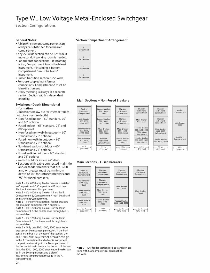
General Notes:• A blank/instrument compartment can always be substituted for a breaker compartment.• Any 22” wide section can be 32” wide if more conduit working room is needed.• For bus duct connections – if incoming is top, Compartment A must be blank/ instrument, if incoming is bottom, Compartment D must be blank/ instrument.• Bussed transition section is 22” wide• For close coupled transformer connections, Compartment A must be blank/instrument.• Utility metering is always in a separate section. Section width is dependent on utility.
Switchgear Depth Dimensional Information(Dimensions below are for internal frames –not total structure depth)• Non-fused indoor – 60” standard, 70” and 80” optional• Fused indoor – 65” standard, 75” and 80” optional• Non-fused non-walk-in outdoor – 60” standard and 75” optional• Fused non-walk-in outdoor – 65” standard and 75” optional• Non-fused walk-in outdoor – 60” standard and 75” optional• Fused walk-in outdoor – 65” standard and 75” optional• Walk-in outdoor aisle is 42” deep• Sections with cable connected main, tie and/or feeder breakers that are 3200 amp or greater must be minimum depth of 70” for unfused breakers and 75” for fused breakers.
Note 1 – If a 4000 amp feeder breaker is installed in Compartment C, Compartment D must be a Blank or Instrument Compartment.Note 2 – If a 4000 amp breaker is installed inCompartment B, Compartment A must be a Blank or Instrument Compartment.Note 3 – If incoming is bottom, feeder breakers can mount in compartments A and/or B.Note 4 – If a 3200 amp breaker is installed inCompartment B, the middle level through bus is not available.
Note 5 – If a 3200 amp breaker is installed inCompartment D, the lower level through bus is not available.Note 6 – Only one 800, 1600, 2000 amp feeder breaker can be mounted per section. If the hori-zontal main bus is at the top of the section, the 800, 1600, 2000 amp feeder breaker can go in the A compartment and a blank/ instrument compartment must go in the D compartment. If the horizontal main bus is a the bottom of the sec-tion, the 800, 1600, 2000 amp feeder breaker can go in the D compartment and a blank/ instrument compartment must go in the A compartment.
Note 7 – Any feeder section (or bus transition sec-tion) with 6000 amp vertical bus must be 32” wide.
Section Compartment Arrangement
Main Sections – Non-Fused Breakers
Main Sections – Fused Breakers

Type WL Low Voltage Metal-Enclosed Switchgear
25
Section Configurations
Tie Sections – Non-Fused Breakers
Main and Tie Sections – Non-Fused Breakers
Main and Tie Sections – Non-Fused Breakers
Feeder Sections – Non-Fused Breakers (see Note 7 on page24)
Tie Sections – Fused Breakers
Main and Tie Sections – Fused Breakers
Main and Tie Sections – Fused Breakers
Feeder Sections – Fused Breakers (see Note 7 on page24)

Type WL Low Voltage Metal-Enclosed Switchgear
26
Shipping Weights and Dimensional Information
Siemens Type WL Low Voltage Switchgear can be configured in many ways by combining different section types. Up to five vertical sections plus a transition section can be shipped together as a unit. Maximum shipping split length for indoor structures is 110 in. (2794 mm). If all vertical sections are not to be shipped as a unit, specifications need to be provided that describe the limiting factors (e.g., low door or narrow hallway).
Normal indoor vertical sections are 96 in.(2438 mm) high and a minimum 60 in.(1524 mm) deep for non-fused breakers and 65 in. (1651 mm) deep for fused breakers. A top-mounted hoist, which is shipped as an accessory in a separate container, adds 6.2 in. (157 mm) for a total installed height of 102.2 in. (2596 mm).
The outdoor switchgear assembly contains the indoor assembly in an outdoor housing. The overall height is 112.8 in. (2865 mm) for non walk-in designs and 114 in.
(2896 mm) for walk-in designs. The depth of a non walk-in outdoor assembly with a 60 in. (1524 mm) internal structure is 82.3 in. (2090 mm) and the depth of a walk-in outdoor assembly with a 60 in. (1524 mm) internal structure is 110.7 in. (2812 mm). Maximum shipping split length for outdoor structures is 66 in. (1676 mm).
The major assembly sections include: • Transition Sections – used as transition to liquid filled transformer or to outdoor dry type transformers. • Auxiliary Sections – used as incoming bus duct or cable entrance when a main breaker is not used. • Main Sections – used to contain main breaker and may house metering and feeder breakers. • Feeder Sections – used to contain feeder breakers and other equipment such as instrumentation. • Tie Sections – used to contain tie breaker and other equipment such as feeder breakers. Transition Section For Liquid Filled and
Outdoor Dry Type Transformers
Dimension A in inches (mm)
Weight in lbs. (kg)
Indoor 55 (1397) 500 (227)
Outdoor 61 (1549) 550 (250)
Approximate Weight – Lbs.
Section Type 22” Indoor
22” Outdoor
32” Indoor
32” Outdoor
38” Indoor
48” Indoor
48” Outdoor
Auxiliary 1000 (450)
2000 (900)
1300 (585)
2500 (1125)
1800 (810)
N/A N/A
Utility Metering
N/A N/A N/A N/A 2100 (945)
2600 (1170)
4500 (2025)
Breaker 1400 (630)
2400 (1080)
2000 (900)
3300 (1485)
N/A N/A N/A
Weights shown in pounds and ( ) kilograms. Weights shown do not include weight of circuit breaker removeable element (but does include cradle). Add 400 lbs for hoist and track. On outdoor switchgear, add 500 lbs for end walls (weight is for both ends). Refer to shipping documents for actual weights.

Type WL Low Voltage Metal-Enclosed Switchgear
27
Dimensional Information
Note: Dimensions shown in inches and (mm). 1 Reduce by 7.88” if upper neutral is present with cables above or if a lower neutral is present with cables below. 2 Reduce by 4.00” if an 800-3200A breaker is located in the bottom compartment. Reductions per notes 1 & 2 are additive. Example: cables below + lower neutral + 2000A breaker in bottom compartment = B-11.88. 3 Reduce cable space by 4.00” x 4.82” if Neutral Riser is present. (Consult Factory). 4 4.10 (104) if W=22; 4.60 (117) if W=32.
A Equipment Depth Direction of cables B C D60” Non-Fused with (N, S, H or L Class Breakers) OR 65” Fused with (F Class Breakers)
Below 21.50 (546) 1 2 13.88 (353) 32.59 (828)
Above 21.25 (540) 1 18.88 (480) 37.59 (955)
70” Non-fused with (N, S, H or L-Class Breakers) OR 75” Fused with (F-Class Breakers)
Below 31.50 (800) 1 2 13.88 (353) 32.59 (828)
Above 31.25 (794) 1 18.88 (480) 37.59 (955)
80” Non-fused with (N, S, H or L-Class Breakers)
Below 41.50 (1054) 1 213.88 (353) 36.50 (927)
Above 41.25 (1048) 1
80” Fused with (F-Class Breakers)
Below 36.50 (927) 1 218.88 (480) 37.59 (955)
Above 36.25 (921)1
Indoor Floor Plan and Cable Space Details

Type WL Low Voltage Metal-Enclosed Switchgear
28
Dimensional Information
Side view
Installation
�
Optional Hoist
24.9�(632)�hoist�
Extension
�
���
102.2 �(2596)�top of�Hoist
Lifting Holes (3) Vent stack
Front �Compartment
E
Bus�Compartment�
17.8�(452)
Cable�Compartment
F
42.0 (1067) �Minimum�Aisle Space�Recommended
Floor Line
2.37�(60)
92.0�(2337)
4.0 (102)
A
G
Figure 10. Typical Indoor Side View
Side view
Equipment depth Breaker compartment depth Rear compartment depth Anchor bolt spacing
60 (1524) Non-fused breakers 19.8 (503) 22.4 (569) 59.13 (1502)
65 (1651) Fused breakers 24.8 (630) 22.4 (569) 64.13 (1629)
70 (1778) Non-fused breakers 19.8 (503) 32.4 (823) 69.13 (1756)
75 (1905) Fused breakers 24.8 (630) 32.4 (823) 74.13 (1883)
80 (2032) Non-fused breakers 19.8 (503) 42.4 (1077) 79.13 (2010)
80 (2032) Fused breakers 24.8 (630) 37.4 (950) 79.13 (2010)
A E F G
12 Type WL Switchgear Instruction and Installation Guide
A Equipment Depth
E Breaker compartment depth
F Rear compartment depth
G Anchor bolt spacing
60 (1524) Non-fused breakers 19.8 (503) 22.4 (569) 59.13 (1502)
65 (1651) Fused breakers 24.8 (630) 22.4 (569) 64.13 (1629)
70 (1778) Non-fused breakers 19.8 (503) 32.4 (823) 69.13 (1756)
75 (1905) Fused breakers 24.8 (630) 32.4 (823) 74.13 (2010)
80 (2032) Non-fused breakers 19.8 (503) 42.4 (1077) 79.13 (2010)
80 (2032) Fused breakers 24.8 (630) 37.4 (950) 79.13 (2010)
Note: Dimensions shown in inches and (mm).

Type WL Low Voltage Metal-Enclosed Switchgear
29
Dimensional Information
1 60" is representative for a 60" deep switchgear internal structure. For other internal structure depths (65 or 75) add extra depth to 60" that is shown. 2 75.37 is representative for a 60" deep internal structure. For other internal structure depths (65 or 75) add extra depth to 75.37 that is shown.
3 Refer to appropriate indoor plan view for available customer conduit information.
Dimensions shown in inches (mm) 1 82.27 dimension is based on 60” internal frame structure and if a deeper internal frame structure is used (65 or 75) the extra depth should be added to the 82.27 dimension. 2 75.37 dimension is based on 60” internal frame structure and if a deeper internal frame structure is used (65 or 75) the extra depth should be added to the 75.37 dimension.
3 60.43 dimension is based on 60” internal frame structure and if a deeper internal frame structure is used (65 or 75) the extra depth should be added to the 60.43 dimension. 4 73.77 dimension is based on 60” internal frame structure and if a deeper internal frame structure is used (65 or 75) the extra depth should be added to the 73.77 dimension.
Installation
FIgure 11. Typical non walk-in outdoor floor plan and side view
Dimensions shown in inches (mm) 1) 82.27 dimension is based on 60" internal frame structure and if a deeper
internal frame structure is used (65 or 75) the extra depth should be added to the 82.27 dimension.
2) 75.37 dimension is based on 60" internal frame structure and if a deeper internal frame structure is used (65 or 75) the extra depth should be added to the 75.37 dimension.
3) 60.43 dimension is based on 60" internal frame structure and if a deeper internal frame structure is used (65 or 75) the extra depth should be added to the 60.43 dimension.
4) 73.77 dimension is based on 60" internal frame structure and if a deeper internal frame structure is used (65 or 75) the extra depth should be added to the 73.77 dimension.
Outdoor non walk-in side view
1
3
2
1) 60" is representative for a 60" deep switchgear internal structure. For other internal structure depths (65 or 75) add extra depth to 60" that is shown.
2) 75.37 is representative for a 60" deep internal structure. For other internal structure depths (65 or 75) add extra depth to 75.37 that is shown.
3) Refer to appropriate indoor plan view for available customer conduit information.
Outdoor non-walk-in floor plan
Type WL Switchgear Instruction and Installation Guide 13
Outdoor non-walk-in side view
Outdoor non-walk-in floor plan

Type WL Low Voltage Metal-Enclosed Switchgear
30
Outdoor walk-in floor plan
1 60" is representative for a 60" deep switchgear internal structure. For other internal structure depths (65 or 75) add extra depth to 60" that is shown. 2 103.8” is representative for a 60" deep internal structure. For other internal structure depths (65 or 75) add extra depth to 103.8” that is shown.
3 Refer to appropriate indoor plan view for available customer conduit information.
Dimensions shown in inches (mm) 1 110.7” dimension is based on 60” internal frame structure and if a deeper internal frame structure is used (65 or 75) the extra depth should be added to the 110.7” dimension. 2 103.8” dimension is based on 60” internal frame structure and if a deeper internal frame structure is used (65 or 75) the extra depth should be added to the 103.8” dimension.
3 60.43” dimension is based on 60” internal frame structure and if a deeper internal frame structure is used (65 or 75) the extra depth should be added to the 60.43 dimension. 4 102.2” dimension is based on 60” internal frame structure and if a deeper internal frame structure is used (65 or 75) the extra depth should be added to the 102.2” dimension.
Installation
Dimensions shown in inches (mm) 1) 110.7 dimension is based on 60" internal frame structure and if a deeper
internal frame structure is used (65 or 75) the extra depth should be added to the 110.7 dimension.
2) 103.8 dimension is based on 60" internal frame structure and if a deeper internal frame structure is used (65 or 75) the extra depth should be added to the 103.8 dimension.
3) 60.43 dimension is based on 60" internal frame structure and if a deeperinternal frame structure is used (65 or 75) the extra depth should beadded to the 60.43 dimension.
4) 102.2 dimension is based on 60" internal frame structure and if a deeper internal frame structure is used (65 or 75) the extra depth should be added to the 102.2 dimension.
Outdoor walk-in floor plan
1
3
2
Figure 12. Typical outdoor walk-in floor plan and side view
Overall Width
14 Type WL Switchgear Instruction and Installation Guide
1) 60" is representative for a 60" deep switchgear internal structure. For other internal structure depths (65 or 75) add extra depth to 60" that is shown.
2) 103.8" is representative for a 60" deep internal structure. For other internal structure depths (65 or 75) add extra depth to 103.8" that is shown.
3) Refer to appropriate indoor plan view for available customer conduit information.
Outdoor walk-in side view
Installation
Dimensions shown in inches (mm) 1) 110.7 dimension is based on 60" internal frame structure and if a deeper
internal frame structure is used (65 or 75) the extra depth should be added to the 110.7 dimension.
2) 103.8 dimension is based on 60" internal frame structure and if a deeper internal frame structure is used (65 or 75) the extra depth should be added to the 103.8 dimension.
3) 60.43 dimension is based on 60" internal frame structure and if a deeperinternal frame structure is used (65 or 75) the extra depth should beadded to the 60.43 dimension.
4) 102.2 dimension is based on 60" internal frame structure and if a deeper internal frame structure is used (65 or 75) the extra depth should be added to the 102.2 dimension.
Outdoor walk-in floor plan
1
3
2
Figure 12. Typical outdoor walk-in floor plan and side view
Overall Width
14 Type WL Switchgear Instruction and Installation Guide
1) 60" is representative for a 60" deep switchgear internal structure. For other internal structure depths (65 or 75) add extra depth to 60" that is shown.
2) 103.8" is representative for a 60" deep internal structure. For other internal structure depths (65 or 75) add extra depth to 103.8" that is shown.
3) Refer to appropriate indoor plan view for available customer conduit information.
Outdoor walk-in side viewOutdoor walk-in side view
Dimensional Information

Type WL Low Voltage Metal-Enclosed Switchgear
31
VT, CPT, CT Data
Voltage Transformers – External Metering and Relaying
Ratio
Accuracy Class at 60 Hz
Volt-Amp Rating Thermal Rating VA Hertz
Burden
W X Y
600:120 0.6 1.2 1.2 100 150 50/60
480:120 0.6 1.2 1.2 100 150 50/60
288:120 0.6 1.2 1.2 100 150 50/60
Control Power Transformers – 115ºC Rise
kVA Phase Primary Voltage Secondary Voltage
3
Single 240 / 480 120 / 2405
10 1
15 1
Accuracy at 60 Hz Metering Burden (ohms)Ratio B-0.1 B-0.2 B-0.5 B-0.9 B-1.8 Class100.5 1.2 — — — — C5150.5 1.2 — — — — C7200.5 1.2 — — — — C9250.5 1.2 — — — — C12300.5 0.6 0.6 — — — C15400.5 0.6 0.6 1.2 — — C20500.5 0.6 0.6 1.2 — — C25600.5 0.3 0.3 0.6 1.2 1.2 C21800.5 0.3 0.3 0.6 0.6 1.2 C291000.5 0.3 0.3 0.6 0.6 1.2 C351200.5 0.3 0.3 0.3 0.6 0.6 C201500.5 0.3 0.3 0.3 0.3 0.6 C251600.5 0.3 0.3 0.3 0.3 0.6 C272000.5 0.3 0.3 0.3 0.3 0.3 C342500.5 0.3 0.3 0.3 0.3 0.3 C203000.5 0.3 0.3 0.3 0.3 0.3 C21
Accuracy at 60 Hz Metering Burden (ohms)Ratio B-0.1 B-0.2 B-0.5 B-0.9 B-1.8 Class2000.5 0.3 0.3 0.3 0.3 0.3 C202500.5 0.3 0.3 0.3 0.3 0.3 C203000.5 0.3 0.3 0.3 0.3 0.3 C203200.5 0.3 0.3 0.3 0.3 0.3 C204000.5 0.3 0.3 0.3 0.3 0.3 C205000.5 0.3 0.3 0.3 0.3 0.3 C206000.5 0.3 0.3 0.3 0.3 0.3 C20
Current Transformers for FSII WL Breaker Applications - External Metering and Relaying 2
Current Transformers for FSIII WL Breaker Applications – External Metering and Relaying 2
1 Requires complete compartment. 2 Breaker compartment will accept 1 set of CT’s each on top and bottom primary disconnects.

Type WL Low Voltage Metal-Enclosed Switchgear
32
Guide Form Specifications
SECTION [26 23 00] [16430] LOW VOLTAGE SWITCHGEAR, WL
PART 1 - GENERAL
1.1 SCOPEA. This section defines low voltage metal-enclosed switchgear assemblies with drawout circuit breaker elements for use in AC systems, rated 600 V or less.
1.2 RELATED DOCUMENTSA. Drawings and general provisions of the Contract, including General and Supplementary Conditions and Division 1 Specification Sections, apply to this Section.B. Related Sections (where applicable) include the following: 1. Section [26 xx xx] [16xxx] – Medium Voltage Load Break Switches 2. Section [26 12 16] [16271] – Dry Type Substation Transformers 3. Section [26 12 19] [16271] – Liquid Type Substation Transformers 4. Section [26 09 13] [16290] – Electrical Power Monitoring and Control 5. Section [26 43 13] [16289] – Transient-Voltage Suppression for Low Voltage Electrical Power Circuits 6. Section [26 05 73] [16055] – Coordination Study
1.3 SUBMITTALSA. Submit shop drawings and product data for approval and final documentation in the quantities listed according to the Conditions of the Contract. Customer name, customer location and customer order number shall identify all transmittals.B. Documents for Approval: General arrangement drawings showing dimensioned elevation, floor plan, side view and foundation details, oneline diagram showing major features, nameplate legends, schematic diagrams and bill of material.C. Final Documents: Record documentation to include those in 1.03.B and wiring diagrams, list of recommended spare parts, instruction and installation manuals [and certified test reports]D. Product Data: Include features, characteristics and ratings of individual circuit breakers and other components. Also, time-current characteristic curves for over current protective devices, including circuit-breaker trip devices and fusible devices.
1.4 RELATED STANDARDSA. Comply with requirements of latest revisions of applicable industry standards, specifically including the following: 1. ANSI/IEEE C37.20.1 – Metal- Enclosed Low Voltage Power Circuit Breaker Switchgear 2. ANSI/IEEE C37.50 – Test Procedure for Low Voltage AC Power Circuit Breakers Used in Enclosures 3. ANSI/IEEE C37.51 – Conformance Testing of Metal-Enclosed Low Voltage AC Power Circuit Breaker Switchgear Assemblies 4. ANSI/IEEE C37.13 – Low Voltage AC Power Circuit Breakers Used in Enclosures 5. ANSI C37.16 – Preferred Ratings, Related Requirements and Application for Low Voltage Power Circuit Breakers and AC Power Circuit Protectors 6. ANSI/IEEE C37.17 - Trip Devices for AC and General Purpose DC Low Voltage Power Circuit Breakers 7. UL 1558 – Metal-Enclosed Low Voltage Power Circuit Breaker Switchgear 8. UL 1066 – Low Voltage AC and DC Power Circuit Breakers Used in Enclosures 9. NEMA SG5 – Power Switchgear Assemblies 10. NEMA SG3 – Low Voltage Power Circuit BreakersB. Manufacturer Seismic Qualification: The low voltage switchgear shall meet and be certified to seismic requirements specified in the [IBC 2009] International Building Code] [CBC 2010 California Building Code] [ASCE American Society of Civil Engineers 7-10]. 1. The low voltage general purpose dry type transformer shall be complaint with IBC 2009 parameters: a. Building Occupancy Category (as defined in Table 1.1 from ASCE 2010): [I] [II] [III] [IV] b. Seismic Design Category: [A] [B] [C] [D] [E] [F] c. Site Class: [A – Hard Rock] [B - Rock] [C – Very dense soil and soft rock] [D – Stiff soil profile] [E – Soft Soil Profile] [F – Soil vulnerable to potential failure or collapse under seismic loading] as defined in IBC 2006 Table 1613.5.2 Site Class Definitions.
d. Ip – Importance Factor: [1.5 – Components must function after an earthquake for life safety purposes (Building Occupancy Code IV)] [1.25 - Buildings and structures that represent a substantial hazard to human life in the event of failure or that can cause substantial economic impact or mass disruption of day-to-day civilian life (Building Occupancy Code III)] [1.0 – Non-essential buildings. Function not life critical. (Building Occupancy Code I and II)] e. Ss – Mapped Spectral Accelerations for Short Periods at 0.2 seconds – 180%g f. Sds – 5% Damped Design Spectral Response Accelerations for Short Periods at 0.2 seconds – 1.2.g. z/h – Height factor ratio: [___] Note: Ratio is a calculated value equal to the floor the gear is installed on divided by 12. A 6th floor installation is a 0.5 value. A basement or ground floor installation is a 0.0 value. 2. Equipment shall be designed to be located in a concrete and steel, moment-resisting frame building not exceeding 12 stories in height with a minimum story height of 10 feet.
1.5 QUALITY ASSURANCEA. Manufacturer Qualifications: Manufacturer of this equipment shall have a minimum of 5 years experience producing similar electrical equipment. The manufacturer of the switchgear assembly shall be the same manufacturer as the breakers. The manufacturer shall be ISO 9001 or 9002 certified.
1.6 DELIVERY, STORAGE AND HANDLINGA. Deliver products in factory labeled packages. Shipping groups shall not exceed 15 ft. in length.B. Circuit breakers shall be shipped inside their respective cells in which they were factory acceptance tested.C. Store and handle in strict compliance with manufacturer’s instructions and recommendations. Protect from potential damage from weather and construction operations. Store so condensation will not form on or in switchgear and if necessary, apply temporary heat where required to obtain suitable service conditions.

Type WL Low Voltage Metal-Enclosed Switchgear
33
Guide Form Specifications
PART 2 - PRODUCTS 2.1 MANUFACTURERS A. The low voltage switchgear shall be manufactured by Siemens, Type-WL Low Voltage Switchgear or preapproved equal. Approved manufacturers are as follows: 1. SIEMENS - Type-WL Low Voltage Switchgear
2.2 RATINGS A. System Configuration: Switchgear suitable for application in three phase, [60 Hz] [50 Hz], [3 wire] [4 wire] [grounded-neutral] [3 wire ungrounded] [3 wire high- impedance grounded] system.B. Electrical Ratings: 1. Nominal System Voltage: [600 V] [480 V] [240 V] [208 V] [OTHER]. 2. Maximum Design Voltage: [635 volts with non-fused breakers] [600 volts with fused breakers] 3. Short-Circuit Current: [100kA] [150kA] [200kA] 4. Main-Bus Continuous Current: [1600] [2000] [3200] [4000] [5000] [6000] A. 5. [Neutral Bus Continuous Current:] [50] [100] percent of main phase bus
2.3 GENERAL REQUIREMENTS A. The switchgear shall be factory assembled and tested and comply with applicable industry standards. It shall be a coordinated design so that shipping groups are easily connected together at the site into a continuous line-up. Necessary connecting materials shall be furnished. All power circuit breakers and assemblies shall be produced by a single manufacturer.B. The switchgear assembly shall consist of one or more metal-enclosed sections in an [indoor NEMA 1 enclosure] [outdoor NEMA 3R non walk-in enclosure] [outdoor NEMA 3R walk-in enclosure]. 1. End sections shall include provisions for main bus extension and installation of future vertical sections. 2. The design shall incorporate preformed steel channels, angles and structural components bolted together and reinforced to form a rigid, self-supporting assembly. 3. Fabricate enclosure with removable, [rear cover panels, secured by captive screws], [hinged rear doors with captive screws] [hinged rear doors with three-point latch and padlockable handle] to allow access to rear interior of switchgear.
C. Front breaker doors and covers must be free of any ventilation openings.D. Horizontal barriers are to be provided to form individual circuit breaker or metering compartments. Circuit breaker compartments are to be barriered from the bus compartment through a primary disconnect assembly. Each circuit breaker or metering compartment shall be provided with a hinged front door secured with hand- operated [lockable] rotary latches.E. Circuit breaker compartments shall include stationary primary contact disconnects that shall be silver-plated copper at the connection points and of one-piece construction. 1. The upper set of disconnects shall bolt directly to the main bus and, for feeder circuit breakers, the lower set shall extend to the rear cable area and shall be insulated where they pass through the main bus compartment. 2. Primary disconnects shall be sized for the maximum continuous current for the frame size of the circuit breaker which is located in the compartment. 3. Interlocks shall be provided to prevent a circuit breaker element of the incorrect frame size or interrupting rating from being inserted into the compartment. 4. Secondary control and communication connections, when required, shall be located in a separately accessed area that is accessible from the front of the switchgear without opening the breaker compartment door or exposing any power cables or bussing. The secondary control contacts shall be of the sliding contact design, silver plated and engage the drawout circuit breaker element in the “connected” and “test” positions.F. All control wiring within the assembly shall be continuous and shall terminate on each end at a suitable terminal block. Control wiring shall be 14-gauge minimum, stranded type SIS and shall be labeled at each end with sleeve-type wire markers. 1. Wire markers shall be machine imprinted with the wire name as indicated on the wiring diagrams. 2. Terminals shall be insulated locking fork or ring tongue type except where connecting to components that do not accept these terminations. Control wiring for external connections
shall be terminated in a separate front accessible compartment for ease of access. G. Finish: Steel parts shall be prepared for painting by a five-stage wash system consisting of an alkaline cleaner, fresh water rise, iron phosphate treatment, fresh water rise and non-chromate sealer. After cleaning and stabilization, the steel parts shall be coated with a thermosetting polyester powder applied with electrostatic equipment at a nominal 2 mils dry film thickness and then cured properly. The paint finish shall have a pencil hardness of 2H, a salt spray rating as defined in ASTM B-117-73 of 600 hours. Paint color shall be ANSI 61 light gray.H. Bus isolation barriers shall be arranged to isolate the buses on either side of each main and tie circuit breaker from each other.I. [Incoming line isolation barriers shall be arranged to isolate the incoming line connections from the main horizontal and vertical bus].J. Main bus shall connect vertical sections and shall be uniform capacity the entire length of assembly. Vertical and horizontal bus bar shall utilize a channel shape design to maximize short circuit withstand capability and minimize heat rise. The main horizontal bus shall be run in a vertical, edge-to-edge arrangement for high short circuit strength. Access to the rear cable termination area shall be possible without reaching over the main and vertical bus. 1. Bus shall be [98 % minimum conductivity copper silver-plated over entire length of the bus bar] [98 % conductivity copper tinplated over entire length of the bus bar]. 2. Feeder Circuit-Breaker Load Terminals: Plated copper bus extensions equipped with pressure connectors for outgoing circuit conductors. 3. Ground Bus shall be copper of 98 % minimum conductivity, minimum size 1/4 by 3 inches. 4. Bus bracing shall be equal to the short circuit interrupting rating of the lowest rated circuit breaker applied in the assembly or 100kA minimum. 5. Provide for future extensions from either end of main phase, neutral and ground bus by means of predrilled bolt holes and connecting links.
Type WL Low Voltage Metal-Enclosed Switchgear
34
K. Bus/Cable compartment barriers: Barriers shall be supplied to isolate the rear cable area from the main bus area. L. [Insulated bus bar shall consist of bus bars enclosed in factory-applied, flame retardant UL recognized insulation system. Bolted bus joints shall be insulated with secure joint covers that can easily be removed and reinstalled.]M.[Low Voltage High-Resistance Grounding System] [Installed in the switchgear assembly] [Contained in separate NEMA 1 enclosure] for use on [480 V] [600 V] [wye] [delta] source, including the following components: 1. Meter relay (MR) 2. 3 Indicating lights: white for “Normal,” red for “Ground Fault” green for “Pulsing” 3. ”Reset“ push button 4. ”Test“ push button 5. On - Off switches for system and pulse 6. Repeat cycle timer, set to produce approx. 30 current pulses per minute 7. Neutral grounding resistor assembly 8. Pulse resistor assembly 9. Test resistor assembly 10. Relay for repeat cycle timer 11. Alarm relay, with extra interlocks for remote alarm (59X) 12. Control power transformer 13. Neutral ammeter & current transformer 14. Optional Portable clamp on ammeter 15. [3 Grounding transformers for generating a neutral CPT] (For Delta System without a system neutral N. Outdoor NEMA 3R Non Walk- In enclosure shall consist of indoor switchgear assemblies in weather resistant steel housing. Enclosure shall be painted steel, integral structural-steel base frame with factory-applied asphalt undercoating. Each section shall be equipped with the following features: 1. Structural design and anchorage adequate to resist loads imposed by 125-mph wind. 2. Space heater operating at [full] [one-half of] rated voltage, sized to prevent condensation. 3. Louvers equipped with insect/ rodent screen and filter and arranged to permit air circulation while excluding exterior dust and rodents. 4. Internal aisle of sufficient width to permit protective-device withdrawal.
5. Load center for distribution of power to lights, receptacles and heaters. 6. Incandescent lighting receptacles with three-way switch. 7. Duplex receptacle with ground fault protection. O. Outdoor NEMA 3R Walk-In enclosure shall consist of indoor switchgear assemblies in weather-resistant steel housing having an operating aisle space of approximately 42 inches. Enclosure shall be painted steel, integral structural-steel base frame with factory-applied asphalt undercoating. Each section shall be equipped with the following features: 1. Structural design and anchorage adequate to resist loads imposed by 125-mph wind. 2. Space heater operating at [full] [one-half of] rated voltage, sized to prevent condensation. 3. Louvers equipped with insect/ rodent screen and filter and arranged to permit air circulation while excluding exterior dust and rodents. 4. Internal aisle of sufficient width to permit protective-device withdrawal, disassembly and servicing in aisle. 5. Aisle access doors with outside padlocking provisions and interior panic latches. 6. Adequate incandescent lighting receptacles with three-way switch at each access door. 7. A duplex receptacle with ground fault protection, at aisle access door. 8. A load center shall be supplied for distribution of power to lights, receptacles and heaters. 9. Aisle ventilation louvers equipped with insect/rodent screen and filter and arranged to permit air circulation while excluding exterior dust and rodents.P. Remote Racking 1. A remote racking device shall be supplied to allow qualified personnel to rack Siemens Type WL breakers into Connect, Test and Disconnect positions from up to 30 feet away from the breaker and outside the arc flash hazard boundary. 2. The remote racking device shall support utilization on any Frame Size 2 or Frame Size 3 WL breaker (including fuse carriage on fused Frame Size 3 WL breaker). 3. The remote racking device shall be portable and weigh less than 30 pounds (excluding cables and remote control panel).
4. The remote racking device shall have integral torque overload sensing to prevent damage to the breaker racking mechanism. 5. The remote racking device shall allow breaker to be racked to any position (disconnect, test, connect) regardless of the starting position of the breaker and without the need for user input as to the starting position. 6. The remote racking device shall support field retrofit on Type WL Low Voltage Switchgear.]
2.4 COMPONENTSA. Instrument Transformers: Comply with IEEE C57.13. 1. Potential Transformers: Secondary voltage rating of 120 V and NEMA accuracy class of 0.6 with burdens of W, X and Y. 2. Current Transformers: Ratios as indicated; burden and accuracy class suitable for connected relays, meters and instruments.B. Multifunction Digital-Metering Monitors shall be UL-listed or recognized, microprocessor-based unit suitable for three or four wire systems. Units shall be mounted in the instrument compartment door and as follows: 1. Incoming monitoring or main breakers: a. The main(s) shall be monitored. 1.) The metering shall be accomplished with a Siemens Model [[PAC3100] [PAC3200] [PAC4200] [9340] [9360] [9510] [9510ADR/RTU] [9610]] digital meter. 2. Feeder breakers: a. Each feeder circuit breaker shall be monitored. 1.) The metering shall be accomplished with a Siemens Model [PAC3100] [PAC3200] [PAC4200] digital meters on each feeder. 2.) Each trip unit shall provide an LCD display for metering.C. Provision for Future Devices: Equip future circuit breaker compartments with rails, mounting brackets, supports, necessary appurtenances and bus connections.D. Control Power Supply: Control power transformer supplying 120-V control circuits through secondary disconnect devices are to be dry-type transformers with primary and secondary fuses.
Guide Form Specifications

Type WL Low Voltage Metal-Enclosed Switchgear
35
Guide Form Specifications
1. Transformers shall be mounted in auxiliary compartments. 2. Multiple source with control power transfer. Two control power transformers located in separate compartments with necessary interlocking relays shall be provided. a. Each transformer shall be connected to line side of associated main circuit breaker. b. Secondary windings connected through a relay or relays to control bus to affect an automatic control power transfer scheme. 3. [24] [48] [125] volt DC battery systemE. Mimic Bus: Continuous mimic bus applied to front of switchgear, arranged in single-line diagram format, shall indicate the arrangement of the circuit breakers in the power circuit.
2.5 CIRCUIT BREAKERSA. Circuit breakers shall comply with the requirements of IEEE/ANSI C37.13/16/17/50,UL1066, NEMA SG3. All breakers shall be three-pole, 100% rated type WL low voltage power breaker manufactured by Siemens Industry, or approved equal. 1. Circuit beaker element shall have connected, test and disconnected position indicators, spring charged/ discharged indicators and circuit breaker open or closed and ready to close indicators all of which shall be visible to the operator with the compartment door closed. It shall be possible to rack the circuit breaker element from the connected to the disconnected position with the compartment door closed otherwise known as “through the door drawout”. 2. Provide interlocks to prevent racking the circuit breaker unless the breaker is open. 3. Raking handle shall be integral to the breaker.B. Ratings: Interrupting up to 100 kA at 480V without fuses. Short time current ratings for each circuit breaker shall be as indicated on the drawings or data tables. Circuit breakers shall be 600- volt class.C. Operating Mechanism: Mechanically and electrically trip-free, stored-energy operating mechanism with the following features: 1. Normal Closing Speed: independent of both control and operator.
2. Electrical operator, field installable with manual charging. 3. Operations counter.D. Each low voltage power circuit breaker shall be equipped with self-powered, microprocessor-based trip-device to sense overload and short circuit conditions. The device shall measure true RMS current. The tripping system shall consist of Rogowski coil sensors on each phase, a release mechanism and the following features: 1. Field Installable and interchangeable so that any trip unit can be used with any frame size circuit breaker. Trip units can be upgraded for future expansion in functionality, such as communication. 2. Functions: Long time, short time and extended instantaneous protection function shall be provided {EIP} to allow the breaker to be applied at the withstand rating of the breaker with minus 0% tolerance so that there is no instantaneous override whatsoever. This feature shall furthermore allow the circuit breaker to be applied up to the full instantaneous rating of the breaker on systems where the available fault current exceeds the breakers withstand rating. Each shall have an adjustable pick-up setting. In addition, long time and short time bands shall each have adjustable time delay. Short time function shall include a switchable I2t ramp and optionally I4t to improve co-ordination with fuses or inverse relays. 3. A software program shall be made available free of charge to support system co-ordination studies .The software will allow time current curves to be generated for the chosen settings. 4. Individual LED’s shall indicate an overcurrent, short circuit or ground fault trip condition. The data shall be maintained for a minimum of 48 hours without the need for a separate battery. 5. Time-current characteristics shall be field adjustable locally or optionally remotely via a bus system [ModBus] [Profibus] [Ethernet]. 6. Current Adjustability: Dial settings and rating plugs on trip units. 7. Pickup Points: 10 Long Time Settings
8. Field Installable Ground-fault protection with at least three time- delay bands. Adjustable current pickup and an I2t ramp. Arrange to provide protection for [three-wire] [four-wire] service. 9. Field installable zone selective interlocking: Connections will be made between main, tie and feeder circuit breakers to ensure that the circuit breaker closest to the fault trips for short time and ground fault conditions. 10. Field Installable Communications shall be provided per schedule. 11. A LCD display shall be available to simplify settings & viewing data locally. 12. The option to remotely switch protection settings shall be provided whenever a generator is part of the power distribution system. 13. Field installable configurable [analog], [digital] output relays shall be available to connect directly to the trip unit 14. Waveform display option on LCD display ETU776 only 15. Estimated contact wear shall be capable of being communicated remotely in addition to a local mechanical indication flag.E. MOC {mechanism operated cell switch} operated by the circuit breaker operating mechanismF. Terminal Block Connections, shall be front mounted and utilize [Screw Type Terminals], [Ring Tongue Terminals], [Tension Spring Terminals]G. Padlocking Provisions: For installing at least three padlocks on each circuit breaker to prevent movement of the drawout mechanism.H. Operating Handle: shall be built in complete with handle and integral to breaker. No external tools shall be required to rack the breaker.I. Control Switch: One for each electrically operated circuit breaker.J. Key Interlocks: Mountings and hardware are included where future installation of key-interlock devices is indicated.K. Undervoltage Trip – field installable: [Instantaneous] [Adjustable time- delay.]L. Shunt-Trip – field installableM. Fused Circuit Breakers: Circuit breaker and fuse combinations must comply with requirements for circuit breakers and trip devices and include the following:
Type WL Low Voltage Metal-Enclosed Switchgear
36
Guide Form Specifications
1. Fuses: NEMA FU 1, Class L current limiting, sized to coordinate with and protect associated circuit breaker. 2. Blown-Fuse Trip Device: fused circuit breakers are to be equipped with blown fuse lockout devices to prevent closing the breaker if a fuse is blown or not present. Open fuse status is indicated at the front of the circuit breaker or fuse drawout element.N. Indicating Lights: To indicate circuit breaker is open or closed, for electrically operated circuit breakers.O. Modular communication and relaying accessories are to be available for retrofitting by the clients chosen engineer. It shall not be necessary for the manufacturers personnel to retrofit accessoriesP. The following items must be capable of being changed in the field: main contacts, CT’s, trip units, racking mechanism and all internal and external accessoriesQ. The main breaker shall have a Dynamic Arc Flash Sentry. The main breaker shall have a dual protective setting capability with graphic waveform display, similar to the Siemens WL breakers ETU776 trip unit. The main breaker will allow the installer to set two different trip curves into one breaker. One curve will be set for standard operating mode and the second curve, with instantaneous protection shall be set for arc flash mode. The switchboard shall be outfitted with a 24 VDC power supply, CubicleBus digital input module, annunciator panel with flashing light and a UPS power supply. The arc flash mode shall be actuated by a [Siguard motion sensor set to the arc flash boundary] [keyed switch] [selector switch]. [A light curtain shall be installed behind the gear to sense open doors on the back of the panel.]
2.6 ACCESSORIESA. Lifting yoke for circuit breakers.B. Portable test set for testing all functions of circuit breaker, solidstate trip devices without removal from switchgear.C. Circuit-Breaker Removal Apparatus: 1. Overhead-circuit-breaker lifting device, track mounted at top front of switchgear, complete with hoist and lifting yokes. Portable, floor- supported, roller-base, elevating carriage arranged for moving circuit breakers in and out of compartments.
D. Spare Fuses: Six, of each type and rating of fuse used. Include spares for potential transformer fuses and control power fuses.E. Spare Indicating Lights: One of each type installed.F. Touchup Paint: One-half pint of paint matching enclosure finish.G. Test Cabinet: Wall mountable cabinet to hold necessary equipment for testing electrically operated breakers.H. Remote Breaker Racking 1. Provide a portable remote breaker racking device system which consists of gear mounted brackets and a cable connected motor operator and control station. 2. The 120v remote breaker racking device shall be attached to the factory mounted switchgear brackets (field retrofit capable) and secured by locking pins. No modification of the gear or circuit breakers shall be required for installation or operation. 3. A single remote breaker racking device shall work on all circuit breaker frame sizes and draw out fuse frames. 4. The remote breaker racking device shall have an on off power switch. 5. The remote breaker racking device shall have torque control to prevent damage to the breaker racking mechanism 6. An operator control station shall be on the end of 30 feet cable to assure the operator is able to locate them self safely. 7. The operator control station shall have the capability of selecting the position desired for the breaker and shall include connected, test and disconnected positions. 8. The operator control station shall contain Start-Stop buttons to initiate the breaker racking. 9. The operator station shall contain indicator lamps showing connected, test and disconnect positions of the breaker as it is racked in or out.
PART 3 - EXECUTION3.1 EXAMINATION AND INSTALLATIONA. Examine elements and surfaces to receive switchgear for compliance with installation tolerances and other conditions affecting performance. Proceed with installation only after unsatisfactory conditions have been corrected.
B. Install and anchor switchgear in accordance with manufacturer’s instructions.
3.2 CONNECTIONSA. Tighten bus joints, electrical connectors and terminals according to manufacturer’s published torque tightening values. Install equipment grounding conductors for switchgear with ground continuity to main electrical ground bus.
3.3 ADJUSTING AND CLEANINGA. Set field-adjustable trip devices per coordination study.B. Clean exposed surfaces using manufacturer recommended materials and methods. Touch-up damaged coating and finishes using non- abrasive materials and methods recommended by manufacturer. Eliminate all visible evidence of repair.
3.4 WARRANTY A. Equipment manufacturer warrants that all goods supplied are free of non-conformities in workmanship and materials for one year from date of initial operation, but not more than eighteen months from date of shipment.
3.5 STARTUP SERVICESA. Engage a factory-authorized service representative to perform startup service.B. Train Owner’s maintenance personnel on procedures and schedules for energizing and de-energizing, troubleshooting, servicing and maintaining equipment and schedules.C. Verify that switchgear is installed and connected according to the Contract Documents.D. Verify that electrical control wiring installation complies with manufacturer’s submittal by means of point-to-point continuity testing. Verify that wiring installation complies with requirements in Division [26] [16] Sections.E. Complete installation and startup checks according to manufacturer’s written instructions.
END OF SECTION

Note: This guide does not purport to cover all details in equipment, or to provide for every possible contingency. Should further information be desired or should particular problems arise, which are not covered sufficiently for the purchaser’s pirpose, the matter should be referred to the local Siemens sales office. The contents of this guide shall not become part of or modify any prior or existing agreement, commitment or relationship.

Published by Siemens Industry, Inc. 2017.
Siemens Industry, Inc. 5400 Triangle Parkway Norcross, GA 30092
For more information, please contact our Customer Support Center. Phone: 1-800-241-4453 E-mail: [email protected]
usa.siemens.com/switchgear
Order No.: LVSA-LVMES-1117 BA Printed in U.S.A. © 2017 Siemens Industry, Inc.
The technical data presented in this document is based on an actual case or on as-designed parameters, and therefore should not be relied upon for any specific application and does not constitute a performance guarantee for any projects. Actual results are dependent on variable conditions. Accordingly, Siemens does not make representations, warranties, or assurances as to the accuracy, currency or completeness of the content contained herein. If requested, we will provide specific technical data or specifications with respect to any customer‘s particular applications. Our company is constantly involved in engineering and development. For that reason, we reserve the right to modify, at any time, the technology and product specifications contained herein.