without/with integrated electronics (obe) pdfs/brh prop valve/brh 4wre(e)_r… · without/with...
TRANSCRIPT

1/204/2 and 4/3 proportional directional valves direct operated, with electrical position feedback, without/with integrated electronics (OBE)Types 4WRE and 4WREE
Nominal sizes 6 and 10Component series 2XMaximum operating pressure 315 barMaximum flow: 80 l/min (NS6) 180 l/min (NS10)
RE 29061/10.05Replaces: 02.03
Type 4WRE 6 …-2X/G24K4/V with plug-in connectors and associated control electronics(separate order)
Type 4WREE 10 …-2X/G24K31/A1Vwith integrated electronics (OBE)
H5732H5881
Overview of contents
Contents Page
Features 1
Ordering details 2
Symbols 3
Function, section 4
Technical data 5, 6
Control electronics 6
Electrical connections, plug-in connectors 7, 8
Integrated electronics (OBE) for type 4WREE 8, 9
Characteristic curves 10...15
Unit dimensions 16...19
Features
– Direct operated proportional directional valve with electrical posisiton feedback and integrated electronics (OBE) for type 4WREE
– Closed loop control of the direction and size of a flow
– Operation is by proportional solenoids with a central thread and removable coil
– For subplate mounting: Porting pattern to ISO 4401Subplates to catalogue sheets RE 45052 (NS6) or RE 45054 (NS10), separate order, see pages 16 ...19
– Spring centred control spool
– Control electronics• 4WREE - integrated electronics (OBE) with voltage input or current input (A1 resp. F1)
• 4WRE (4/3 version), separate order: - digital or analogue amplifier in Eurocard format - analogue module amplifier
• 4WRE…A (4/2 version), separate order: - analogue module amplifier
For information regarding the available spare parts see:www.boschrexroth.com/spc
Court
esy
of CM
A/F
lodyn
e/H
ydra
dyn
e
Motion C
ontr
ol
Hyd
raulic
P
neu
mat
ic
Ele
ctrica
l
Mec
han
ical
(
800)
426-5
480
ww
w.c
maf
h.c
om

P T
A B
a 0 b
A B
P T
a 0
2/20 Bosch Rexroth AG Hydraulics 4WRE; 4WREE RE 29061/10.05
Ordering details
Further details in clear text
Seal materialV = FKM seals,
suitable for mineral oil (HL, HLP) to DIN 51524
Electronic interfaces A1 or F1 For 4WREE
A1 = Command value input ± 10 VDCF1 = Command value input 4 to 20 mANo code = For 4WRE
Electrical connectionsFor 4WRE:
K4 = Without plug-in connector, with component plug
to DIN EN 175301-803Plug-in connector (solenoid, position
transducer). separate order, see page 7
For 4WREE:K31 = Without plug-in connector, with
component plug to DIN EN 175201-804Plug-in connector – separate order,
see page 8
G24 = Power supply voltage 24 VDC
2X = Component series 20 to 29(20 to 29: unchanged installation and
connection dimensions)
Nominal flow at a valve pressure differential ∆p = 10 barNS6
08 = 8 l/min16 = 16 l/min32 = 32 l/min
NS1025 = 25 l/min50 = 50 l/min75 = 75 l/min
4WRE 2X G24 V *
Without integratedelectronics (OBE) = No codeWith integratedelectronics (OBE) = E
Nominal size 6 = 6Nominal size 10 = 10
Spool symbols
= E E1–
= V
= W W1–
= EA
= WA
With symbols E1and W1:P → A: qV max B → T: qV/2P → B: qV/2 A → T: qV max
Note:For spools W and WA there is, in the neutral position, a connection between A to T and B to T with approx. 3 % of the relevant nominal cross-section.
Court
esy
of CM
A/F
lodyn
e/H
ydra
dyn
e
Motion C
ontr
ol
Hyd
raulic
P
neu
mat
ic
Ele
ctrica
l
Mec
han
ical
(
800)
426-5
480
ww
w.c
maf
h.c
om

G
A B
P T
a 0 ba b
G
A B
P T
a 0a b
G A B
P T
a 0 ba b
G A B
P T
a 0a b
Hydraulics Bosch Rexroth AGRE 29061/10.05 4WRE; 4WREE 3/20
Symbols
Proportional directional valves without integrated electronics
Type 4WRE…
Type 4WRE…A…
Proportional directional valves with integrated electronics
Type 4WREE…
Type 4WREE…A…
Court
esy
of CM
A/F
lodyn
e/H
ydra
dyn
e
Motion C
ontr
ol
Hyd
raulic
P
neu
mat
ic
Ele
ctrica
l
Mec
han
ical
(
800)
426-5
480
ww
w.c
maf
h.c
om

BA
a b
9 7 5 3 2 10 1 4 11 6
A T B(P)
9 7 5 3 2 1 4 11 6
A T B(P)
a b
P1 P2
X1 X2
X1
X2
P1 P2
8
4/20 Bosch Rexroth AG Hydraulics 4WRE; 4WREE RE 29061/10.05
Function, section
Type 4WRE 6…-2X/…
Type 4WREE 6…-2X/…
The 4/2 and 4/3 proportional directional valves are direct operated components of subplate mounting design. They are operated by proportional solenoids with central thread and removalbe coil. The solenoids are optionally controlled by either external electronics (type 4WRE) or by the integrated electronics (type 4WREE).
Design:
The valve basically consists of:
– Housing (1) with mounting face
– Control spool (2) with compression springs (3 and 4) and spring plates (X1 and X2)
– Solenoids (5 and 6) and pole tubes (P1 and P2) with central thread
– Position transducer (7)
– Optional integrated control electronics (8)
– The mechanical zero point adjustment (9) is accessible via the Pg13.5 and the electrical zero point is accessible via the Pg7 (10) (type 4WREE)
Function:
– With the solenoids (5 and 6), de-energised, the control spool (2) is held in the central position by the compression springs (3 and 4) between the spring plates (X1 and X2)
– Direct operation of the control spool (2) by energising one of the proportional solenoids, e.g. control of solenoid "b" (6)
→ Movement of the control spool (2) to the left in proportion to the electrical input signal
→ Connection from P to A and B to T via orifice-like cross- sections with progressive flow characteristics
– De-energising of solenoids (6)
→ The control spool (2) is returned to the central position via the compression spring (3)
In the de-energised condition the spool (2) is held in a mechanical centre position by the solenoid return springs. This, for the spool symbol "V", does not relate to the hydraulic centre position! When the electrical valve closed loop control circuit is closed then the spool is positioned in the hydraulic centre position.
Note for type 4WRE 6…-2X/…
Draining of the tank line is to be prevented. Taking the insallation conditions into account a back pressure is to be fitted (back pressure approx. 2 bar).
Valve with 2 switching positions: (type 4WRE…A…)
The function of this valve version is basically the same as that of the valve with 3 switched positions. The 2 switched position valves are however only fitted with solenoid "a" (5). a plug (11) is fitted in place on the 2nd proportional solenoid.
Court
esy
of CM
A/F
lodyn
e/H
ydra
dyn
e
Motion C
ontr
ol
Hyd
raulic
P
neu
mat
ic
Ele
ctrica
l
Mec
han
ical
(
800)
426-5
480
ww
w.c
maf
h.c
om

Hydraulics Bosch Rexroth AGRE 29061/10.05 4WRE; 4WREE 5/20
Technical data (for applications outside these parameters, please consult us!)
GeneralNominal size NS 6 10
Installation optional, preferably horizontal
Storage temperature range °C –20 to +80
Ambient 4WRE °C –20 to +70
temperature range 4WREE °C –20 to +50
Weight 4WRE kg 2.2 6.3
4WREE kg 2.4 6.5
Hydraulic (measured with HLP46, ϑoil = 40 °C ± 5 °C and p =100 bar)
Max. operating pressure Ports A, B, P bar 315
Port T bar 210
Nominal flow qV nom at ∆p = 10 bar l/min 8, 16, 32 25, 50, 75
Max. permissible flow l/min 80 180
Pressure fluid Mineral oil (HL, HLP) to DIN 51524 other pressure fluids on request!
Pressure fluid temperature range °C –20 to +80 (preferably +40 to +50)
Viscosity range mm2/s 20 to 380 (preferably 30 to 46)
Max. permissible degree of pressure fluid contamination.Cleanliness class to ISO 4406 (c)
class 20/18/15 1)
Hysteresis % ≤ 0.1
Reversal span % ≤ 0.05
Response sensitivity % ≤ 0.05
Zero point displacement with changes to the %/10 K 0.15
pressure fluid temperature and operating temperature %/100 bar 0.1
1) The cleanliness class stated for the components must be adhered too in hydraulic systems. Effective filtration prevents faults from occurring and at the same time increases the component service life.For the selection of filters see catalogue sheets RE 50070, RE 50076, RE 50081, RE 50086 and RE 50088.
Court
esy
of CM
A/F
lodyn
e/H
ydra
dyn
e
Motion C
ontr
ol
Hyd
raulic
P
neu
mat
ic
Ele
ctrica
l
Mec
han
ical
(
800)
426-5
480
ww
w.c
maf
h.c
om

6/20 Bosch Rexroth AG Hydraulics 4WRE; 4WREE RE 29061/10.05
Technical data (for applications outside these parameters, please consult us!)
ElectricalNominal size NS 6 10
Voltage type DC
Command value signal Voltage input „A1“ V ±10 (see page 8)
for 4WREE Current input „F1“ mA 4 bis 20 (see page 8)
Solenoid coil Cold value at 20 °C Ω 2.7 3.7
resistance Max. warm value Ω 4.05 5.55
Duty % 100
Max. coil temperature 1) °C 150
Electrical connections 4WRE with component plug DIN EN 175301-803 and ISO 4400
see pages 7 and 8 plug-in connector to DIN EN 175301-803 and ISO 4400 2)
4WREE with component plug DIN EN 175201-804
plug-in connector DIN EN 175201-804 2)
Valve protection to EN 60529 IP65 with mounted and fixed plug-in connector
1) Due to the occurring surface temperature of the solenoid coils, the European Standards EN 563 and EN 982 are to be taken into account!
2) Separate order
Note: For details regarding the environmental simulation test covering EMC (electro- magnetic compatibility), climate and mechanical loading see RE 29061-U (declaration regarding environmental compatibility).
Control electronicsFor 4WRE 4/3 version
Amplifier in Eurocard format 2)
digital VT-VRPD-2-2X/V0/0 to RE 30126
analogue VT-VRPA2-1-1X/V0 to RE 30119
VT-VRPA2-2-1X/V0 to RE 30119
Modular amplifier 2) analogue VT-MRPA2-1 to RE 30219
VT-MRPA2-2 to RE 30219
For 4WRE…A… 4/2 version
Modular amplifier 2) analogue VT-MRPA1-1 to RE 30219
VT-MRPA1-2 to RE 30219
For 4WREE integrated in the valve, see page 9
Analogue command value module VT- SWMA-1-1X/... to RE 29902
Analogue command value module VT-SWMKA-1-1X/... to RE 29903
Analogue command value card VT-SWKA-1-1X/... to RE 30255
Digital command value card VT-HACD -1-1X/... to RE 30143
Supply voltage Nominal voltage VDC 24
Lower limiting value V 19.4
Upper limiting value V 35
Amplifier power Imax A < 2
consumption Impulse current A 3
Court
esy
of CM
A/F
lodyn
e/H
ydra
dyn
e
Motion C
ontr
ol
Hyd
raulic
P
neu
mat
ic
Ele
ctrica
l
Mec
han
ical
(
800)
426-5
480
ww
w.c
maf
h.c
om

PE
1 2
PE
1 2
PE
1 2
PE
1 2
37
Ø 1
5
Pg7
23
7,8
16
2 14 3
4 21 3
27,5
18
43 10
34,2
5,5
1
1
210A250V
GD
M
Hydraulics Bosch Rexroth AGRE 29061/10.05 4WRE; 4WREE 7/20
Electrical connections, plug-in connectors (nominal dimensions in mm)
For type 4WRE (without integrated electronics)
Plug-in connector CECC 75 301-803-A002FA-H3D08-G to DIN EN 175301-803 and ISO 4400
Solenoid a, colour greySeparate order under Material No. R901017010
Solenoid b, colour blackSeparate order under Material No. R901017011
To the amplifier To the amplifier
Connections on the component plug Connections on the plug-in connector
Plug-in connector 4-pin Pg7-G4W1F
Separate order under Material No. R900023126
Connection cable:
Recommended: Up to 50 m cable length type LiYCY 4 x 0.25 mm2
Only connect screen to PE on the supply side.
Inductive position transducer
Coil connections
To th
e am
plifi
erSignal ground
SupplySignal
Connection to the plug connector
Supply ground
To the amplifier
Coil
1 fixing screw M3Tightening torque MA = 0,5 Nm
Court
esy
of CM
A/F
lodyn
e/H
ydra
dyn
e
Motion C
ontr
ol
Hyd
raulic
P
neu
mat
ic
Ele
ctrica
l
Mec
han
ical
(
800)
426-5
480
ww
w.c
maf
h.c
om

A F
ED
C
B
Ø6,
5…11
Ø27
91
Ø8…
Ø13
,5
85
8/20 Bosch Rexroth AG Hydraulics 4WRE; 4WREE RE 29061/10.05
Integrated electronics (OBE) for type 4WREE (nominal dimensions in mm)
For type 4WREE (with integrated electronics (OBE)
Plug-in connector to DIN EN 175201-804Separate order under Material No. R900021267 (plastic version)
Angled form – separate order under Material No. R9000217845
Fo pin allocation also see block circuit diagram, page 9
Plug-in connector to DIN EN 175201-804Separate order under Material No. R900223890 (metal version)
Component plug allocation Contact Interface A1 signal Interface F1 signal
Supply voltage A 24 VDC (u(t) = 19.4 to 35 V); Imax = 2 A
B 0 V
Reference potential actual value C ref. contact F; Re > 50 kΩ ref. contact F; Re < 10 Ω
Differential amplifier input D ± 10 V command value; Re > 50 kΩ 4 to 20 mA command value; Re > 100 Ω
E reference potentional command value
Measurement output (actual value) F ± 10 V actual value (limiting load 5 mA)
4 to 20 mA actual value, load resistance max. 300 Ω
PE connected with cooling body and valve housing
Command value: A positive command value 0 to +10 V (or 12 to 20 mA) at D and the reference potential at E results in a flow from P to A and B to T. A negative command value 0 to –10 V (or 12 to 4 mA) at D and the reference potential at E results in a flow from P to B and A to T.
For a valve with 1 solenoid on side a (e.g. spool variants EA and WA) a positive command value 0 to +10 V (or 4 to 20 mA) at D and the reference po ten ti al at E results in a flow from P to B and A to T.
Actual value: Actual value 0 to +10 V resp. 12 to 20 mA at F and the reference potential at C results in flow from P to A and B to T, 0 to –10 V resp. 4 to 12 mA results in flow from P to B and A to T. For a valve with 1 solenoid results 4 to 20 mA at F and the reference potential at C results in flow from P to A and B to T.
Connection cable: Recommended: – up to 25 m cable length type LiYCY 7 x 0.75 mm2
– up to 50 m cable length type LiYCY 7 x 1.0 mm2
For outside diameter see plug-in connector sketch
Only connect screen to PE on the supply line.
Court
esy
of CM
A/F
lodyn
e/H
ydra
dyn
e
Motion C
ontr
ol
Hyd
raulic
P
neu
mat
ic
Ele
ctrica
l
Mec
han
ical
(
800)
426-5
480
ww
w.c
maf
h.c
om
UU
UU
UI
UI
=≈
=≈
D
E
F
C
A
B
PE
UU
+ Ui
– Ui0 V
WREE 6 W1-08-20/G24K31/A1V0000003A035276
FA
B
CED
Zero
00929812
B
P T
A
a 0 b ba G
2154557301
2)3)
E
FA
B
CD
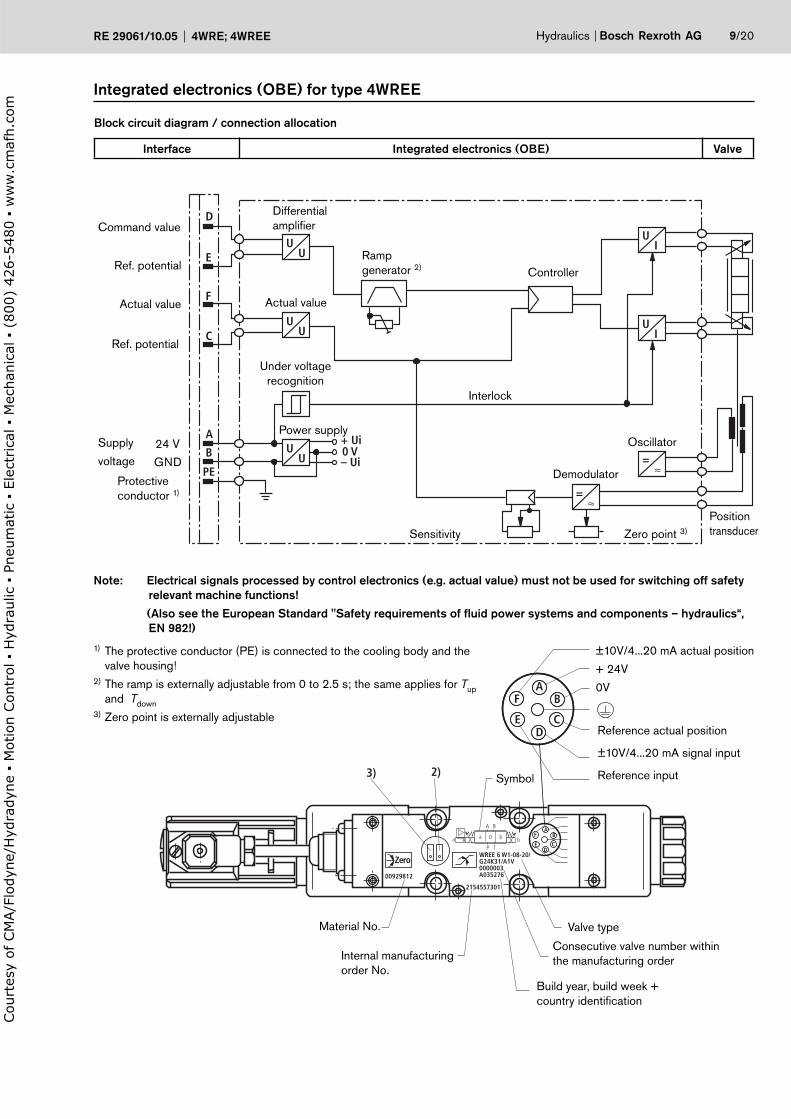
±10V/4...20 mA actual position
+ 24V
0V
Reference actual position
±10V/4...20 mA signal input
Reference input
Hydraulics Bosch Rexroth AGRE 29061/10.05 4WRE; 4WREE 9/20
Block circuit diagram / connection allocation
Interface Integrated electronics (OBE) Valve
Integrated electronics (OBE) for type 4WREE
Build year, build week + country identification
DifferentialamplifierCommand value
Ref. po ten ti alRamp generator 2)
Actual value Actual value
Protectiveconductor 1)
Supply
voltageDemodulator
OscillatorPower supply
Position transducerZero point 3)Sensitivity
Controller
Note: Electrical signals processed by control electronics (e.g. actual value) must not be used for switching off safety relevant machine functions!
(Also see the European Standard "Safety requirements of fluid power systems and components – hydraulics“, EN 982!)
1) The protective conductor (PE) is connected to the cooling body and the valve housing!
2) The ramp is externally adjustable from 0 to 2.5 s; the same applies for Tup and Tdown
3) Zero point is externally adjustable
Under voltagerecognition
Interlock
24 V
GND
Ref. po ten ti al
Valve type
Consecutive valve number within the manufacturing order
Material No.
Internal manufacturing order No.
Symbol
Court
esy
of CM
A/F
lodyn
e/H
ydra
dyn
e
Motion C
ontr
ol
Hyd
raulic
P
neu
mat
ic
Ele
ctrica
l
Mec
han
ical
(
800)
426-5
480
ww
w.c
maf
h.c
om

1
2
0 50 100 150 200 250 300 315210
100
80
60
40
20
– 20
– 40
– 60
– 80
– 100
– 5 – 3 – 1 1 3 5
100
80
60
40
20
– 20
– 40
– 60
– 80
– 100
– 5 – 3 – 1 1 3 5
1
2
0 50 100 150 200 250 300 315210
10/20 Bosch Rexroth AG Hydraulics 4WRE; 4WREE RE 29061/10.05
Characteristic curves for type 4WREE (measured with HLP46, ϑoil = 40 °C ± 5 °C) NS6 and 10
Pressure-signal-characteristic curves (V spool), ps = 100 bar
NS6
← in % →UE
UEN
Leak
age
flow
in l/
min
→
Operating pressure in bar → Operating pressure in bar →
Type 4WREE 10 V75Type 4WREE 6 V32
Leak
age
flow
in l/
min
→
∆pL
p S
←
in
% →
Leakage flow with the spool in the central position
NS10
← in % →UE
UEN
∆pL
p S
←
in
% →
Court
esy
of CM
A/F
lodyn
e/H
ydra
dyn
e
Motion C
ontr
ol
Hyd
raulic
P
neu
mat
ic
Ele
ctrica
l
Mec
han
ical
(
800)
426-5
480
ww
w.c
maf
h.c
om

30
20
10
0 10 20 30 40 50 60 70 80 90 100
40
50
60
4
3
2
1
5
70
80
90
100
110
120
30
20
10
0 10 20 30 40 50 60 70 80 90 100
4321
5
30
20
10
0 10 20 30 40 50 60 70 80 90 100
40
50
60
4
3
2
1
5
15 20 30 40 50 60 70 80 90 100
15 20 30 40 50 60 70 80 90 100
15 20 30 40 50 60 70 80 90 100
Hydraulics Bosch Rexroth AGRE 29061/10.05 4WRE; 4WREE 11/20
Characterisitc curves for type 4WREE (measured with HLP46, ϑoil = 40 °C ± 5 °C and p =100 bar) NS6Fl
ow in
l/m
in →
Command value in % →
Flow
in l/
min
→Fl
ow in
l/m
in →
8 l/min nominal flow at a 10 bar valve pressure differential
Max. permissible fl owNote:Take the performance limits on page 15 into account!
1 ∆p = 10 bar constant
2 ∆p = 20 bar constant
3 ∆p = 30 bar constant
4 ∆p = 50 bar constant
5 ∆p = 100 bar constant
∆p = Valve pressure differential (inlet pressure pP minus load pressure pL minus return pressure pT)
V spool
E and W spools
16 l/min nominal flow at a 10 bar valve pressure differential
32 l/min nominal flow at a 10 bar valve pressure differential
P → A / B → T
or
P → B / A → T
P → A / B → T
or
P → B / A → T
P → A / B → T
or
P → B / A → T
V spool
E and W spools
V spool
E and W spools
Command value in % →
Command value in % →
1 ∆p = 10 bar constant
2 ∆p = 20 bar constant
3 ∆p = 30 bar constant
4 ∆p = 50 bar constant
5 ∆p = 100 bar constant
1 ∆p = 10 bar constant
2 ∆p = 20 bar constant
3 ∆p = 30 bar constant
4 ∆p = 50 bar constant
5 ∆p = 100 bar constant
Court
esy
of CM
A/F
lodyn
e/H
ydra
dyn
e
Motion C
ontr
ol
Hyd
raulic
P
neu
mat
ic
Ele
ctrica
l
Mec
han
ical
(
800)
426-5
480
ww
w.c
maf
h.c
om
75
50
25
0 10 20 30 40 50 60 70 80 90 100
100
125
150
4
3
2
1
5
175
200
225
250
275
300
180
75
50
25
0 10 20 30 40 50 60 70 80 90 100
100
125
150
4
3
2
1
5
30
20
10
0 10 20 30 40 50 60 70 80 90 100
40
50
80
4
3
2
1
5
60
70
10 20 30 40 50 60 70 80 90 100
10 20 30 40 50 60 70 80 90 100
10 20 30 40 50 60 70 80 90 100
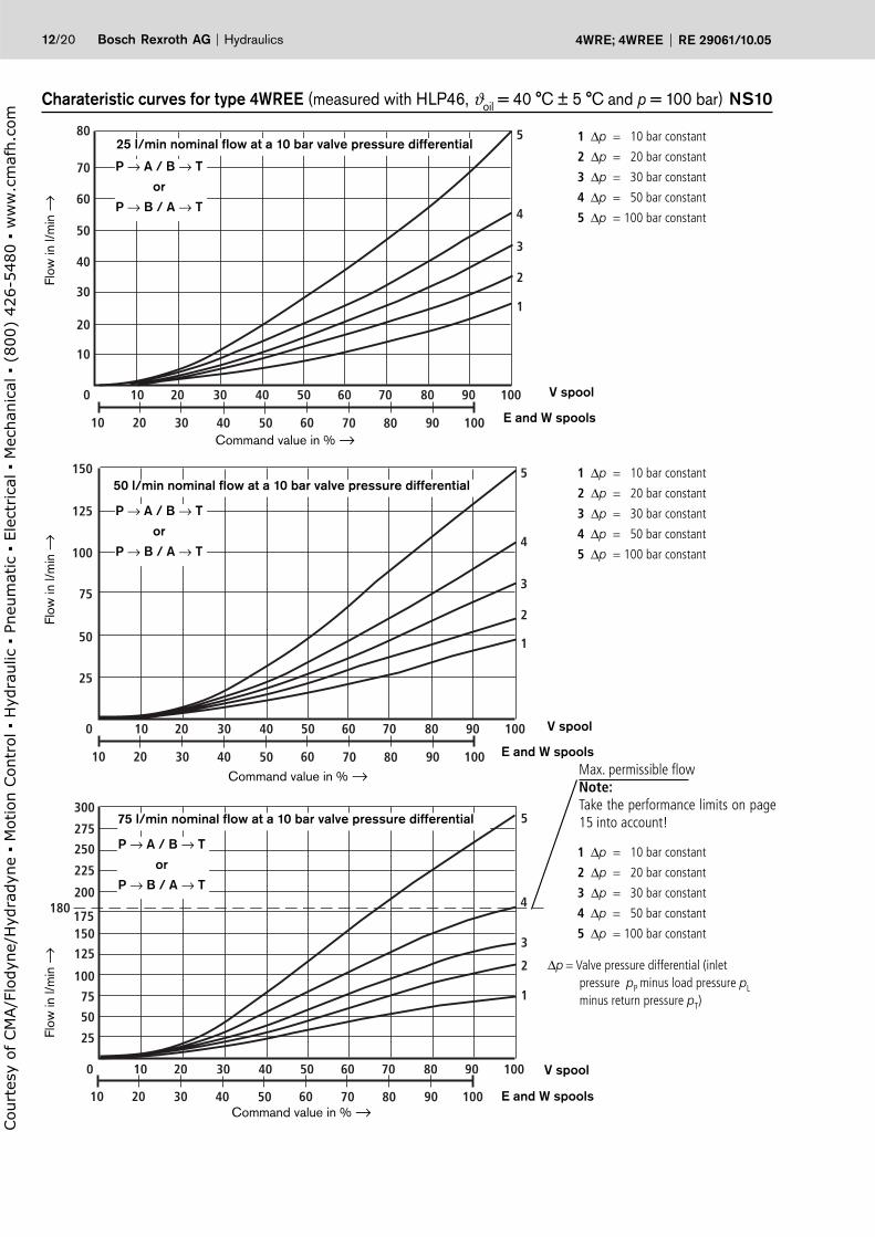
12/20 Bosch Rexroth AG Hydraulics 4WRE; 4WREE RE 29061/10.05
Charateristic curves for type 4WREE (measured with HLP46, ϑoil = 40 °C ± 5 °C and p = 100 bar) NS10
Flow
in l/
min
→
Command value in % →
Flow
in l/
min
→Fl
ow in
l/m
in →
25 l/min nominal flow at a 10 bar valve pressure differential
Max. permissible fl owNote:Take the performance limits on page 15 into account!
∆p = Valve pressure differential (inlet pressure pP minus load pressure pL minus return pressure pT)
V spool
E and W spools
50 l/min nominal flow at a 10 bar valve pressure differential
75 l/min nominal flow at a 10 bar valve pressure differential
P → A / B → T
or
P → B / A → T
P → A / B → T
or
P → B / A → T
P → A / B → T
or
P → B / A → T
V spool
E and W spools
V spool
E and W spools
Command value in % →
Command value in % →
1 ∆p = 10 bar constant
2 ∆p = 20 bar constant
3 ∆p = 30 bar constant
4 ∆p = 50 bar constant
5 ∆p = 100 bar constant
1 ∆p = 10 bar constant
2 ∆p = 20 bar constant
3 ∆p = 30 bar constant
4 ∆p = 50 bar constant
5 ∆p = 100 bar constant
1 ∆p = 10 bar constant
2 ∆p = 20 bar constant
3 ∆p = 30 bar constant
4 ∆p = 50 bar constant
5 ∆p = 100 bar constant
Court
esy
of CM
A/F
lodyn
e/H
ydra
dyn
e
Motion C
ontr
ol
Hyd
raulic
P
neu
mat
ic
Ele
ctrica
l
Mec
han
ical
(
800)
426-5
480
ww
w.c
maf
h.c
om

0 10 20 30
0 – 100 – 0
0 – 75 – 0
0 – 50 – 0
0 – 25 – 0
0 10 20 30 40
10
20
30
40
50
60
70
80
90
100
–30
–25
–20
–15
–10
–5
0
5
1 10 100 20020 30 50
–3
–315
–270
–225
–180
–135
–90
–45
0
Hydraulics Bosch Rexroth AGRE 29061/10.05 4WRE; 4WREE 13/20
Frequency response characteristic curves for type 4WREE (measured with HLP46, ϑoil = 40 °C ± 5 °C, ps = 10 bar) NS6
Pha
se a
ngle
in °
→
Signal ± 10 %
Signal ± 25 %
Signal ± 100 %
Am
plitu
de re
latio
nshi
p in
dB
→
Frequency in Hz →
Str
oke
in %
→
Signal change in %
Transient function with a stepped form of electrical input signal for type 4WREE NS6(measured with HLP46, ϑoil = 40 °C ± 5 °C and ps =10 bar)
Time in ms →
4/3 valve version
Spool symbol „E“
4/3 valve version
Spool symbol „V“
Court
esy
of CM
A/F
lodyn
e/H
ydra
dyn
e
Motion C
ontr
ol
Hyd
raulic
P
neu
mat
ic
Ele
ctrica
l
Mec
han
ical
(
800)
426-5
480
ww
w.c
maf
h.c
om
0
25
50
75
100
20 40 60 20 40 60
0 – 25 – 0
0 – 50 – 0
0 – 75 – 0
0 – 100 – 0
0
–30
–25
–20
–15
–10
–5
0
5
1 10 100
–315
–270
–225
–180
–135
0
20020 30 50
–3
–45
–90
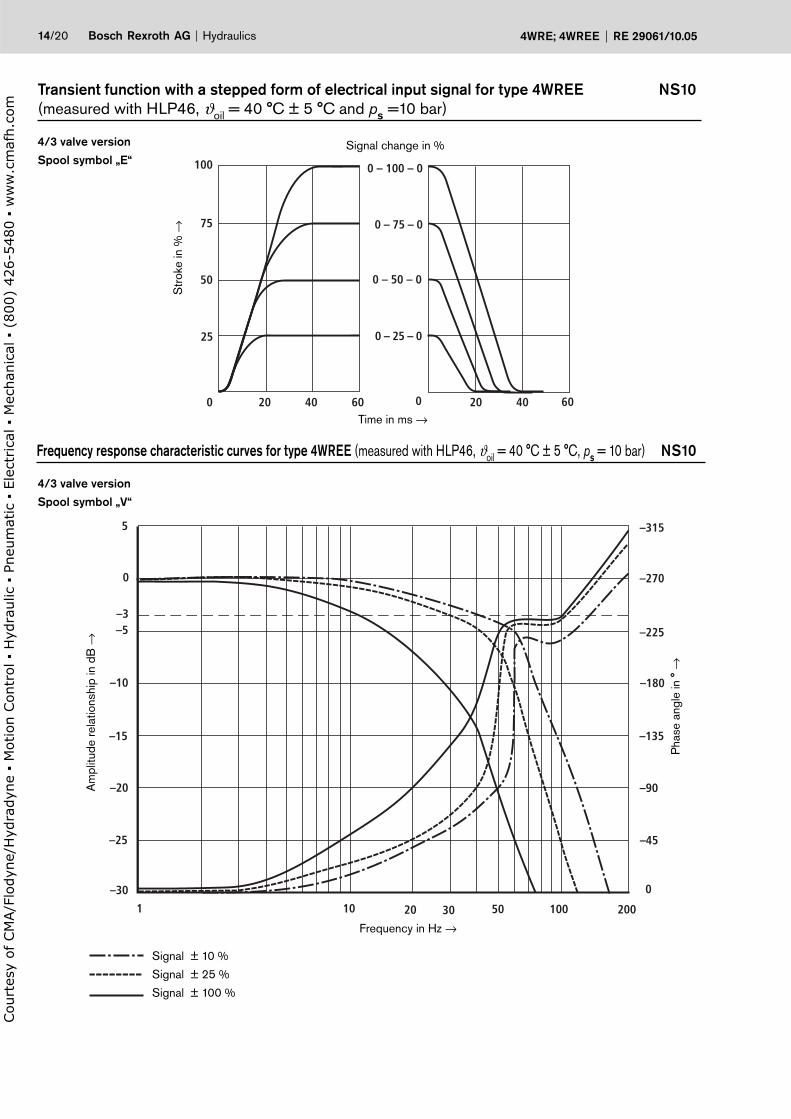
14/20 Bosch Rexroth AG Hydraulics 4WRE; 4WREE RE 29061/10.05
Transient function with a stepped form of electrical input signal for type 4WREE NS10(measured with HLP46, ϑoil = 40 °C ± 5 °C and ps =10 bar)
4/3 valve version
Spool symbol „E“
4/3 valve version
Spool symbol „V“
Pha
se a
ngle
in °
→
Signal ± 10 %
Signal ± 25 %
Signal ± 100 %
Am
plitu
de re
latio
nshi
p in
dB
→
Frequency in Hz →
Str
oke
in %
→
Signal change in %
Time in ms →
Frequency response characteristic curves for type 4WREE (measured with HLP46, ϑoil = 40 °C ± 5 °C, ps = 10 bar) NS10
Court
esy
of CM
A/F
lodyn
e/H
ydra
dyn
e
Motion C
ontr
ol
Hyd
raulic
P
neu
mat
ic
Ele
ctrica
l
Mec
han
ical
(
800)
426-5
480
ww
w.c
maf
h.c
om

1
10
100
10 20 50 100 200
200
300
80
08
16
32
10
100
10 10020 50 200 300
25
50
400
25
180
qVmax ≈ 375l/min
50
75
Hydraulics Bosch Rexroth AGRE 29061/10.05 4WRE; 4WREE 15/20
Flow for type 4WREE (measured with HLP46, ϑoil = 40 °C ± 5 °C) NS10
Flow for type 4WREE (measured with HLP46, ϑoil = 40 °C ± 5 °C) NS6
Load function with maximum valve opening
Nominal flows 25, 50 and 75 l/min
Spool symbol „V“
Max. permissible
flow
Take the maximum permissible flow of 80 l/min into account!
Take the maximum permissible flow of 180 l/min into account!
Load function with maximum valve opening
Nominal flows 8, 16 and 32 l/min
Spool symbol „V“
Max. permissible
flowFl
ow in
l/m
in →
Valve pressure differential in bar →
P → A / B → T
or
P → B / A → T
P → A / B → T
or
P → B / A → T
Flow
in l/
min
→
Valve pressure differential in bar →
qVmax = 375 l/min
Court
esy
of CM
A/F
lodyn
e/H
ydra
dyn
e
Motion C
ontr
ol
Hyd
raulic
P
neu
mat
ic
Ele
ctrica
l
Mec
han
ical
(
800)
426-5
480
ww
w.c
maf
h.c
om

2347
85,5
15
44
9
139
203
262
13,569 8,5
5104
78
6
a b42
11
47
72
8
15
T
PA
F4 F3
BF1 F2
12 3
(123)
A B
G
0,01/100mm
Rzmax 4
16/20 Bosch Rexroth AG Hydraulics 4WRE; 4WREE RE 29061/10.05
Unit dimensions: type 4WRE 6 (nominal dimensions in mm) NS6
Required surface finish of the valve mounting surface
1 Valve housing
2 Proportional solenoid "a" with inductive position transducer
3 Proportional solenoid "b"
4 Plug-in connector "A", colour grey, separate order – see page 7
5 Plug-in connector "B", colour black, separate order – see page 7
6 Plug-in connector for inductive position transducer, separate order – see page 7
7 Plug for valves with one solenoid(2 switching positions, versions EA or WA)
8 Identical seal rings for ports A, B, P and T
9 Space required to remove the plug-in connector
10 Name plate
11 Machined valve mounting surface,connection location to ISO 4401 (with locating pin hole) Code: 4401-03-02-0-94 (explanation to ISO 5783)Deviation from the standard:- without locating pin hole „G“- ports P, A, B and T mit Ø8 mm
Subplates to catalogue sheet RE 45052 and valve fixing screws must be ordered separately.
Subplates: G341/01 (G1/4) G342/01 (G3/8) G502/01 (G1/2)
Valve fixing screws (separate order)The following valve fixing screws are recommended:
– 4 S.H.C.S. ISO 4762 - M5 x 50 - 10.9-flZn-240h-L(friction value µtotal = 0.09 to 0.14)Tightening torque MA = 7 Nm ± 10% Material No. R913000064 (separate order)
or
– 4 S.H.C.S. ISO 4762 - M5 x 50 - 10.9(friction value µtotal = 0.12 to 0.17)Tightening torque MA = 8.9 Nm ± 10%
Tolerances to: – General tolerances ISO 2768-mK
Court
esy
of CM
A/F
lodyn
e/H
ydra
dyn
e
Motion C
ontr
ol
Hyd
raulic
P
neu
mat
ic
Ele
ctrica
l
Mec
han
ical
(
800)
426-5
480
ww
w.c
maf
h.c
om

A
P
T
B
44
23
4711
3,5
13 122 10 1
3
(123)
8,513,5
69
203
262
139
a b42
11
8
7
15
47
72
8
T
PA
F4 F3
BF1 F2
G
0,01/100mm
Rzmax 4
Hydraulics Bosch Rexroth AGRE 29061/10.05 4WRE; 4WREE 17/20
1 Valve housing
2 Proportional solenoid "a" with inductive position transducer
3 Proportional solenoid "b"
7 Plug for valves with one solenoid(2 switching positions, versions EA or WA)
8 Identical seal rings for ports A, B, P and T
10 Name plate
11 Machined valve mounting surface,connection location to ISO 4401 (with locating pin hole) Code: 4401-03-02-0-94 (explanation to ISO 5783)Deviation from the standard:- without locating pin hole „G“- ports P, A, B and T mit Ø8 mm
12 Integrated electronics (OBE)
13 Plug-in connector,separate order – see page 8
Unit dimensions: type 4WREE 6 (nominal dimensions in mm) NS6
Required surface finish of the valve mounting surface
Subplates to catalogue sheet RE 45052 and valve fixing screws must be ordered separately.
Subplates: G341/01 (G1/4) G342/01 (G3/8) G502/01 (G1/2)
Valve fixing screws (separate order)The following valve fixing screws are recommended:
– 4 S.H.C.S. ISO 4762 - M5 x 50 - 10.9-flZn-240h-L(friction value µtotal = 0.09 to 0.14)Tightening torque MA = 7 Nm ± 10% Material No. R913000064 (separate order)
or
– 4 S.H.C.S. ISO 4762 - M5 x 50 - 10.9(friction value µtotal = 0.12 to 0.17)Tightening torque MA = 8.9 Nm ± 10%
Tolerances to: – General tolerances ISO 2768-mK
Court
esy
of CM
A/F
lodyn
e/H
ydra
dyn
e
Motion C
ontr
ol
Hyd
raulic
P
neu
mat
ic
Ele
ctrica
l
Mec
han
ical
(
800)
426-5
480
ww
w.c
maf
h.c
om

113,
515
70
9
B
(180,5)
1292
269,5
365
a b
40
72,5
51046
19
32
78
1
30
11
94
20
72
13
F1 F2
BAT1T
F3F4
P
184,5
32,5
±0,2
50,8±0,2
A
0,01/100mm
Rzmax 4
18/20 Bosch Rexroth AG Hydraulics 4WRE; 4WREE RE 29061/10.05
1 Valve housing
2 Proportional solenoid "a" with inductive position transducer
3 Proportional solenoid "b"
4 Plug-in connector "A", colour grey, separate order – see page 7
5 Plug-in connector "B", colour black, separate order – see page 7
6 Plug-in connector for position transducer, separate order – see page 7
7 Plug for valves with one solenoid(2 switching positions, versions EA or WA)
8 Identical seal rings for ports A, B, P, T and T1
9 Space required to remove the plug-in connector
10 Name plate
11 Machined valve mounting surface,connection location to ISO 4401 (with locating pin hole) Code: 4401-05-04-0-94 (explanation toISO 5783)Deviation from the standard: Port T1 Ø11.2 mm
Unit dimensions: type 4WRE 10 (nominal dimensions in mm) NS10
Subplates to catalogue sheet RE 45054 and valve fixing screws must be ordered separately.
Subplates: G66/01 (G3/8) G67/01 (G1/2) G534/01 (G3/4)
Valve fixing screws (separate order)The following valve fixing screws are recommended:
– 4 S.C.H.S. ISO 4762 - M6 x 40 - 10.9-flZn-240h-L(friction value µtotal = 0.09 to 0.14)Tightening torque MA = 12.5 Nm ± 10%, Material No. R913000058 (separate order)
or
– 4 S.C.H.S. ISO 4762 - M6 x 40 - 10.9(friction value µtotal = 0.12 to 0.17)Tightening torque MA = 15,5 Nm ± 10%
Tolerances to: – General tolerances ISO 2768-mK
Required surface finish of the valve mounting surface
Court
esy
of CM
A/F
lodyn
e/H
ydra
dyn
e
Motion C
ontr
ol
Hyd
raulic
P
neu
mat
ic
Ele
ctrica
l
Mec
han
ical
(
800)
426-5
480
ww
w.c
maf
h.c
om

70
1954
A P BT1T Ø
64
92
269,5
365
a b
40
72,5
12
19
10
139
13
30
11
2 1
8
7 3
(180,5)
12
184,5
94
20
72
13
F1 F2
BAT1T
F3F4
P
32,5
±0,2
50,8±0,2
0,01/100mm
Rzmax 4
Hydraulics Bosch Rexroth AGRE 29061/10.05 4WRE; 4WREE 19/20
Unit dimensions: type 4WREE 10 (nominal dimensions in mm) NS10
1 Valve housing
2 Proportional solenoid "a" with inductive position transducer
3 Proportional solenoid "b"
7 Plug for valves with one solenoid(2 switching positions, versions EA or WA)
8 Identical seal rings for ports A, B, P, T and T1
10 Name plate
11 Machined valve mounting surface,connection location to ISO 4401 (with locating pin hole) Code: 4401-05-04-0-94 (explanation to ISO 5783)Deviation from the standard: Port T1 Ø11.2 mm
12 Integrated electronics (OBE)
13 Plug-in connector,separate order – see page 8
Subplates to catalogue sheet RE 45054 and valve fixing screws must be ordered separately.
Subplates: G66/01 (G3/8) G67/01 (G1/2) G534/01 (G3/4)
Valve fixing screws (separate order)The following valve fixing screws are recommended:
– 4 S.C.H.S. ISO 4762 - M6 x 40 - 10.9-flZn-240h-L(friction value µtotal = 0.09 to 0.14)Tightening torque MA = 12.5 Nm ± 10%, Material No. R913000058 (separate order)
or
– 4 S.C.H.S. ISO 4762 - M6 x 40 - 10.9(friction value µtotal = 0.12 to 0.17)Tightening torque MA = 15,5 Nm ± 10%
Tolerances to: – General tolerances ISO 2768-mK
Required surface finish of the valve mounting surface
Court
esy
of CM
A/F
lodyn
e/H
ydra
dyn
e
Motion C
ontr
ol
Hyd
raulic
P
neu
mat
ic
Ele
ctrica
l
Mec
han
ical
(
800)
426-5
480
ww
w.c
maf
h.c
om
Bosch Rexroth AGHydraulicsZum Eisengießer 197816 Lohr am Main, GermanyTelefon +49 (0) 93 52 / 18-0Telefax +49 (0) 93 52 / 18-23 [email protected]
© This document, as well as the data, specifications and other informations set forth in it, are the exclusive property of Bosch Rexroth AG. Without their consent it may not be reproduced or given to third parties.The data specified above only serves to describe the product. No statements concerning a certain condition or suitability for a certain application can be derived from our information. The details stated do not release you from the responsibility for carrying out your own assessment and verification. It must be remembered that our products are subject to a natural process of wear and ageing.
20/20 Bosch Rexroth AG Hydraulics 4WREA; 4 WREE RE 29061/10.05
Notes
Court
esy
of CM
A/F
lodyn
e/H
ydra
dyn
e
Motion C
ontr
ol
Hyd
raulic
P
neu
mat
ic
Ele
ctrica
l
Mec
han
ical
(
800)
426-5
480
ww
w.c
maf
h.c
om