with - world radio history
TRANSCRIPT
4
W6USA AUTO -RESONATOR XMI TER
AN ECO WITH CRYSTAL STABILITY
SUPER- SELECTIVE PHONE SUPERIHET
HIGH PERFORMANCE UHF RECEIVER
30c IN U.S.A. AND CANADA II. 5Y in Un r.:q NingdoT 2s ni
www.americanradiohistory.com
EMA QT'S A
NEW
ION caPpCIy
LOW Val AGE
LOW PRICE
%goo
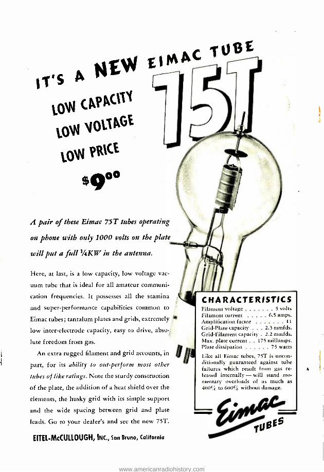
A pair of these Eimac 75T tubes operating
on phone with only 1000 volts on the plate
will put a full 1 /4KW in the antenna.
Here, at last, is a low capacity, low voltage vac-
uum tube that is ideal for all amateur communi-
cation frequencies. It possesses all the stamina
and super -performance capabilities common to
Eimac tubes; tantalum plates and grids, extremely
low inter -electrode capacity, easy to drive, abso-
lute freedom from gas.
An extra rugged filament and grid accounts, in
part, for its ability to out-perform most other
tubes of like ratings. Note the sturdy construction
of the plate, the addition of a heat shield over the
elements, the husky grid with its simple support
and the wide spacing between grid and plate
leads. Go to your dealer's and see the new 75T.
EITEL- McCULLOUGH, INC., San Bruno, California
CHARACTERISTICS Filament voltage 5 volts Filament current 6 5 amps. Amplification factor 11
Grid -Plate capacity ... 2.3 mmfds. Grid -Filament capacity . 2.2 mmfds. Max. plate current . . 175 millamps. Plate dissipation 75 watts
Like all Eimac tubes, 75T is uncon- ditionally guaranteed against tube failures which result from gas re- leased internally - will stand mo- mentary overloads of as much as 400% to 600 % without damage.
0E5
www.americanradiohistory.com
If
£XCITR f
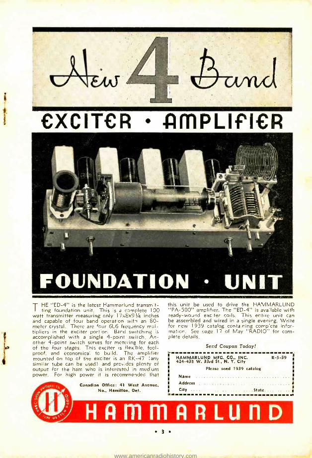
T HE "ED -4" is the latest Hammariund transmit- ! ting foundation unit. This is a complete 100
watt transmitter measuring only 17x8x91/4 inches and capable of four band operation with an 80- meter crystal. There are four 6L6 frequency mul- tipliers in the exciter portion. Band switching is
accomplished with a single 4 -point switch. An- other 4 -point switch serves for metering for each of the four stages. This exciter is flexible, fool- proof, and economical to build. The amplifier mounted on top of the exciter is an RK -47 any similar tube can be used) and provides plenty of output for the ham who is interested in medium power. For high power it is recommended that
Canadian Office: 41 West Avenue, No., Hamilton, Ont.
this unit be used to drive the HAMMARLUND "PA -500" amplifier. The "ED -4" is available with ready -wound exciter coils. This entire unit can be assembled and wired in a single evening. Write for new 1939 catalog conta ping complete infor- mation. See page 17 of May "RADIO" for com- plete details.
Ser.d Coupon Today!
HAMMARLUND MFC. CO., INC. 424 -438 W. 33rd St., N. Y. City
Please send 1939 catalog
R-5-39
Name
Address
City State
3
www.americanradiohistory.com
PADIO 1460 BeverIg Boulevard, Los flogeles Phone. YOrk 7226 Teletype: L A 319 Cables: RediopU ,, Los Angetes
Branch Advertising NEW YORK 101 W. 31 St., Phone: CHickering 4.7399
Offices: CHICAGO, 3606 N. Bernard St., Phone: JUNiper 5575
Production Office EAST STROUDSBURG, PA., 45 Lackawanna Ave.
for "RADIO Phone Stroudsburg 1734 Teletype: 50136 74
rbOf1'OiP01100Nie Direct all manuscripts, subscrip- tion and book orders, payments, and general correspcndence to the home office at Lcs Angeles. Regarding advertising, see notice at right. Unusable, unsolicited manuscripts will be destroyed unless accompanied by a stamped, addressed return en- velope.
Rates SUBSCRIPTION RATES: Two years, $4.00, or $2.50 yearly in U. S. A. (add 3% tax in California), (:routa *, Newfoundland *, Cuba*, and Mexico *. To l'an- American countrie :, awl Spain. $0.50* per year additional Elsewhere!' (except New Zealand), $1.00* per year additional. New Zealand only: 18s.Od. yearly, local currency, from Te Aro Book Dept, Ltd. 14 Court- enay flare, Wellington. Special issues are included only with aubscriptions of one -half year or longer Refunds on
canelled subscriptions will he made at the difference between the rate paid and the rate earned. THREE YEAR SUBSCRIPTIONS at the rate of $5.00, net, in advance, are accepted from the U. S. A. and contiguous countries* only. Such sub- scriptions must be sent tires to our home office, not thrmtgh a :gents.
SINGLE COPY ¡'RICES: Prices are
for regular issues; prices for special issues may vary but are usually those
' shown in parenthesis. .kt newsdealer's, book stores, and radio purrs dealers, 30e (50e) per copy in U. S. A. and
Cariada. By nail, posi paid, from houe office. 30e (50r) in U.S.A., Canada*, Newfoundland* Yuba *, and
Mexico *; 35c* (55e)* in other Pan -
American countries and Spain. Else - wherct, 40c* (05r).* BACK ISSUES, when available, 5e extra net. Back issues will not be
included in subscriptions.
*REMITTANCES must be payable at par in continental U. S. A. except as
follows: Canadian bank, postal, and express orders and postal rotes ac- cepted; add 10e exchange in Canadian batik cheeks. From elsewhere, remit by bank draft (preferred: or inter- national money order.
'BRITISH remittances: fag the con- venience of British customers we quote sterling prices (and accept British pos- tal orders and cheques payable at par in London) valid whenever i l = $4.10 or more. When exchange is lower, in- crease sterling amount proportionately or remit in dollars. Subscriptions: 1
year, 14s. 611.; 2 years, £1 is. S' e.
copies, Is. 8d. (special Pd. -see above),
/'/ V WdV'Yy
a "Raid, + "Raid, EDITOR
V. W. Smith, WGBCX
ASSOCIATE EDITORS
Hay L. Dawley, WGDHG Frank C. Jones, {VGAJF K. V. IC. Lansingh, W GQX
E. H. Conklin, W9111Y CHICAGO
CONTRIBUTING EDITOR
Herbert Becker, W6QD
EDITORIAL AND TECHNICAL ASSISTANTS
Leigh Norton, W6CEM
Faust R. Gonsett, W6VR
jack Rothman, W6KFQ
Kennard D. Moore, W6PDB
F. Ferguson Wormwood, W9TEP, 6
B. A. Ontiveros, W6FFF, Technical Draftsman
Business Staff Los Angeles
K. V. R. Lansingh, Publisher A. McMullen, Managing Editor
Sales Department John Snetsinger, Circulation and Advertising Manager; F. E. Taylor, Assistant Advertising Manager; M. F. Zeis, Chief Subscription Clerk;
J. K. Knorpp, Chief Book Sales Clerk,
New York V. R. Lansingh, Eastern General Manager
H. Olsher, Eastern Advertising Representative.
Chicago C. W. Nelson, Asst. Advertising Manager
East Stroudsburg W. E. McNatt, Ir., Production Manager
Advertising inquiries may he di- rected to our nearest office. For fastest service, prepare adver- tising copy in duplicate; send original copy and cuts ifully mounted and mortised) to East Stroudsburg where "Radio" is printed; send duplicate copy, proofs of cuts, and space order to the advertising department at Los Angeles. No advertisment will run until the home office telegraphs its approval.
Miscellaneous Notices IF YOU MOVE notify us in advance. We rammt replace copies sent to your old address. See "Changes of Address" notice elsewhere in this issue.
Radio is published ten times yearly (including enlarged ` special annual number) about the middle of tie month preceding its date; August and September issues are omitted. PUBLISHED- BY RADIO. Ltd., Tech- nical Publishers, 7460 Beverly Blvd., Los Angeles, California, U.S.A. COPYRIGHT, 1939, shy Radin, Ltd. All rights reserved. Reproduction with- out written permission is prohibited; permission is usually granted amateur radis papers on request.
TITLE REGISTERED at United States I'atent Office:
PRINTED IN U. S.A. by Hughes Printing Company, East Stroudsburg, -
l'ennsy'lvania. RESPONSIBILITY will not be accept- ,
ed for subscriptions placed with un- authorized agents. Prospective sub- scribers are urged to inspect carefully ;he credentials of anyone soliciting their business. Agents are never au- thorized to vary the totes quoted on this page.
BRANCH OFFICES transact a rash business with customers who call in person; mail orders and orders on opt.. account should be sent only. to Los Angeles.
Principal Foreign Agents Europe: N. E. Read, '24, Church St., Oswestry, Shropshire, England. Aus- tralia: "The Bulletin ", Ros 252156, Sydney; MCCBis, 183 Elizabeth St., Melbourne: Swain & Co., Pitt St., Sydney. New Zealand: Te Aro Book Depot. Lid., 634 l'ourtenay flare, Wellington. South America: F. Stark, Crixa 2786, Sao l'auto; " Revista egrafica ", Pent 165, Buenos Air Editorial Pan America, Peru 67 Buenos Aires. South Africa: So
The Ailltautil at t4.ncd444, S3ltatituatie, a#Ici Raziia
RADIO, June, 1939, as. 240. Published monthly except August and September by Radio, Ltd., 7460 Beverly Blvd., Los Angeles, Calif. Entered as second -class matter Feb. 6, 1936, at the postoffice at Los Angeles, Calif., under the Act of March 1879. Additional entry at East Stroudsburg, Pa. Registered for transmission by post as a newspaper
at G.P.O., Wellington, New Zealand.
4
www.americanradiohistory.com
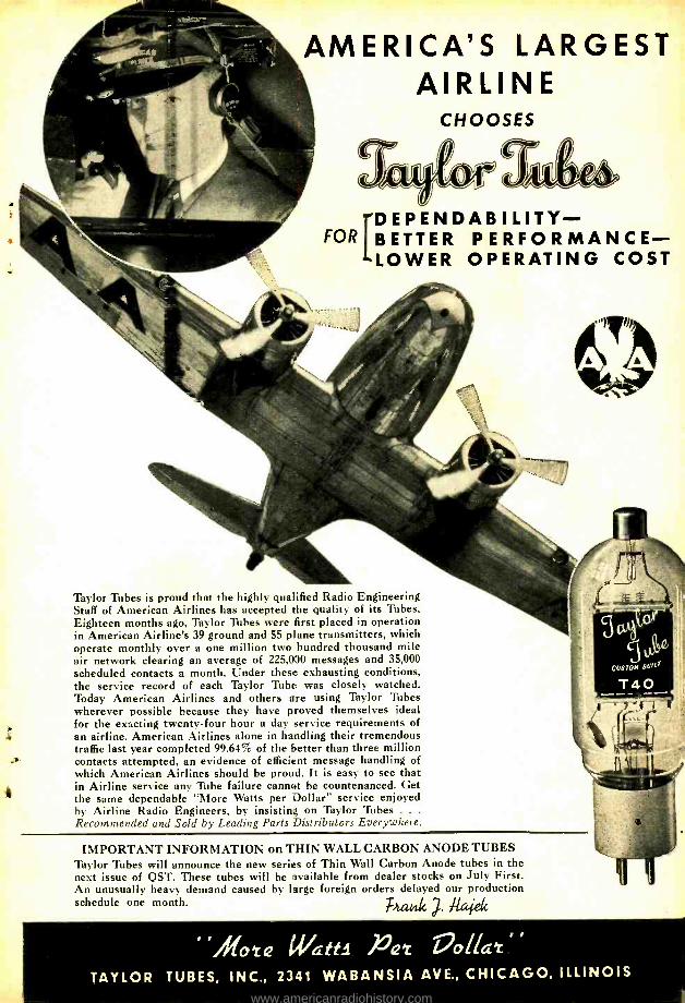
AMERICA'S LARGEST AIRLINE
CHOOSES
D EPENDABILITY - B ETTER PERFORMANCE - LOWER OPERATING COST
Taylor Tubes is proud that the highly qualified Radio Engineering Staff of American Airlines has accepted the quality of its Tubes. Eighteen months ago, Taylor Tubes were first placed in operation in American Airline's 39 ground and 55 plane transmitters, which operate monthly over a one million two hundred thousand mile air network clearing an average of 225,000 messages and 35,000 scheduled contacts a month. Under these exhausting conditions, the service record of each Taylor Tube was closely watched. Today American Airlines and others are using Taylor Tubes wherever possible because they have proved themselves ideal for the exacting twenty -four hour a day service requirements of an airline. American Airlines alone in handling their tremendous traffic last year completed 99.64% of the better than three million contacts attempted, an evidence of efficient message handling of which American Airlines should be proud. It is easy to see that in Airline service any Tube failure cannot be countenanced. Get the same dependable "More Watts per Dollar" service enjoyed by Airline Radio Engineers, by insisting on Taylor Tubes . . .
Recommended and Sold by Leading Parts Distributors Everywhere.
IMPORTANT INFORMATION on THIN WALL CARBON ANODE TUBES Taylor Tubes will announce the new series of Thin Wall Carbon Anode tubes in the next issue of QST. These tubes will be available from dealer stocks on July First. An unusually heavy demand caused by large foreign orders delayed our production schedule one month.
TATARIG ,7. Raje
. Mote watti Pet lvllaz
TAYLOR TUBES, INC., 2341 WABANSIA AVE., CHICAGO, ILLINOIS
www.americanradiohistory.com
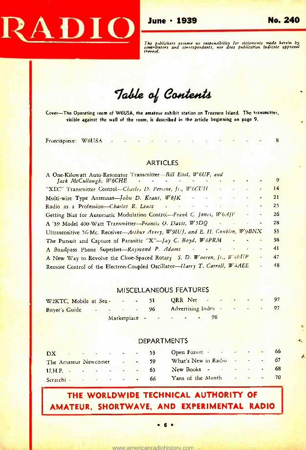
June 1939 No. 240
The publishers assume no responsibility for statements made herein by contributors and correspondents, nor does publication indicate approval thereof.
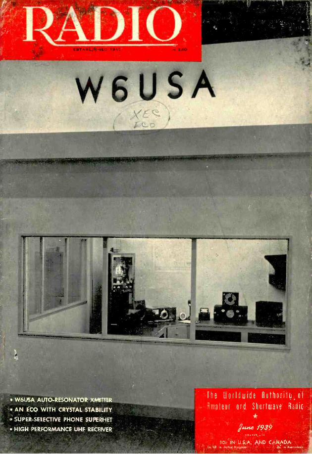
Tale ems. Cover -The Operating room of W6USA, the amateur exhibit station on Treasure Island. The transmitter,
visible against the wall of the room, is described in the article beginning on page 9.
Frontispiece: W6USA - - - - - - - - 8
ARTICLES
A One -Kilowatt Auto -Resonator Transmitter -Bill Eitel, W6UF, and Jack McCullough, W6CHE - - - - - - 9
"XEC" Transmitter Control Charles D. Perriue, Jr., II"6CI'H - - 14
Multi -wire Type Antennas -John D. Kraus, W8JK - - - - 21
Radio as a Profession -Charles R. Leutz - - - - 25
Getting Bias for Automatic Modulation Control -Frank C. Jones, 1U6AJF - 26
A '39 Model 400 -Watt Transmitter -Francis O. Davis, W/5DQ - - 28
Ultrasensitive 56 -Mc. Receiver -Arthur Avery, W9IUJ, and E. H. Conklin, II"9BNX 33
The Pursuit and Capture of Parasitic "X" -Jay C. Boyd, W6PRM - 38
A Bandpass Phone Superhet -Raymond P. Adams - - 41
A New Way to Revolve the Close- Spaced Rotary -S. D. Wooten, Jr., W' -iEUP 47
Remote Control of the Electron -Coupled Oscillator -Harry T. Carroll, W4AEE 48
MISCELLANEOUS FEATURES
W2KTC, Mobile at Sea - 51 QRR Net - 97
Buyer's Guide - 96 Advertising Index - 97
Marketplace - - 98
DEPARTMENTS
DX - 53 Open Forum - 66
The Amateur Newcomer - 59 What's New in Radie 67
U.H.F. - 63 New Books - - - 68
Scratchi - - 66 Yarn of the Month 70
THE WORLDWIDE TECHNICAL AUTHORITY OF
AMATEUR, SHORTWAVE, AND EXPERIMENTAL RADIO
6
www.americanradiohistory.com
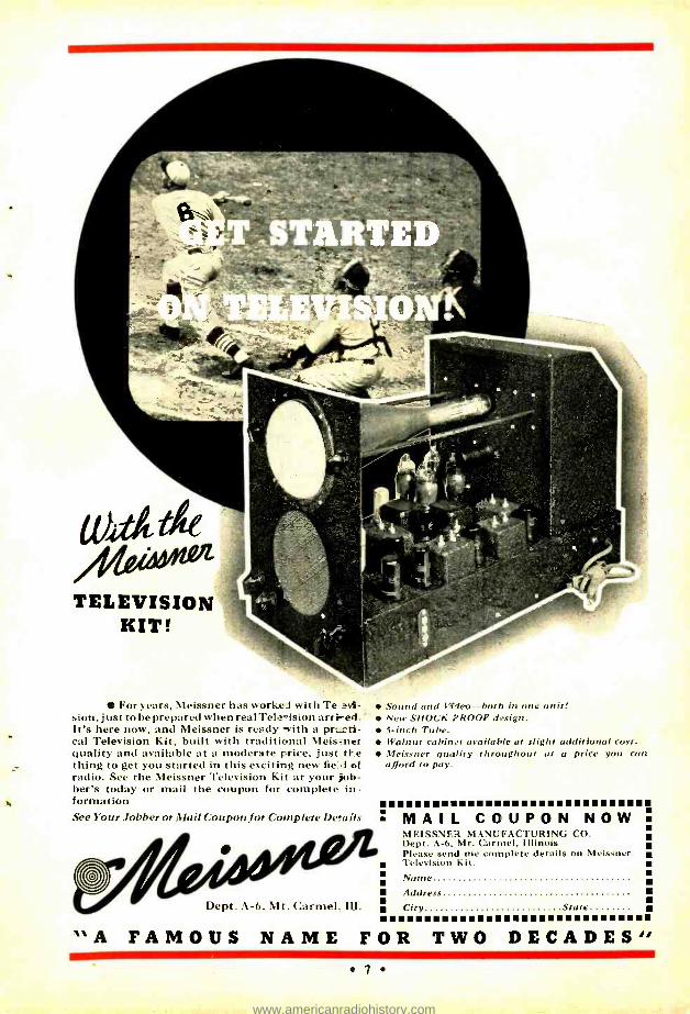
TELEVISION IRIT!
For years, Meissner has work e:1 with Te ?vi- sion, just to be prepared when real Tele -ision aeri -c.l. It's here now, and Meissner is ready with a pr.rti- cal Television Kit, built with traditional Meis-ter quality and available at a moderate price, just tt.e thing to get you started in this exciting new fie:1 of radio. See the Meissner Television Kit at your job- ber's today or mail the coupon for complete in- formation See Your Jobber or Mail Coupon for Complete Details
Sound and Video -both in one unit! Neu, SHOCK PROOF design. 5 -inch Tube. Walnut cabinet available at slight additional cost. Meissner quality throughout at a price you can afford to pay.
Dept. A -6, Mt. Carmel Ill.
........u.. MAIL COUPON NOW MEISSNER MANUFACTURING CO. Dept. A -6, Mt. Carmel, Illinois Please send me complete details on Meissner Television Kit. Name
Address
City Stute .....t "A FAMOUS NAME FOR TWO DECADES'
.7. www.americanradiohistory.com
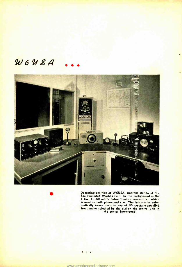
W62rS4 ...
Operating position at W6USA, amar?ur station of the San Francisco World's Fair. In the background is the 1 kw. 10 -80 meter auto- resonator rransmitter, which is used on both phone and c.w. The transmitter auto- matically tunes itself to any of 60 crystal -controlled frequencies selected by the dial on Me control unit in
the center foreground.
g
www.americanradiohistory.com
4 0014-lliLowatt
HHTFREUNATOH TRHMITTEH
By BILL EITEL, W6UF, and ZACK McCULLOUCH, W6CHE
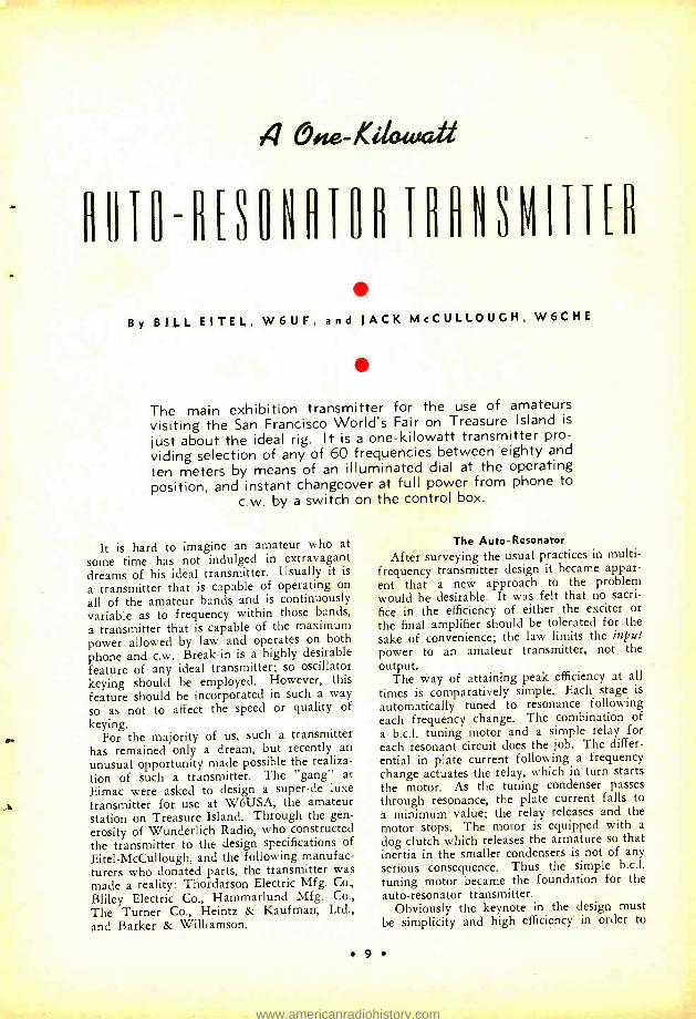
The main exhibition transmitter for the use of amateurs visiting the San Francisco World's Fair on Treasure Island is
just about the ideal rig. It is a one -kilowatt transmitter pro-
viding selection of any of 60 frequencies between eighty and
ten meters by means of an illuminated dial at the operating position, and instant changeover at full power from phone to
c.w. by a switch on the control box.
It is hard to imagine an amateur who at
some time has not indulged in extravagant dreams of his ideal transmitter. Usually it is
a transmitter that is capable of operating on
all of the amateur bands and is continuously variable as to frequency within those bands,
a transmitter that is capable of the maximum power allowed by law and operates on both phone and c.w. Break -in is a highly desirable feature of any ideal transmitter; so oscillator keying should be employed. However, this feature should be incorporated in such a way so as not to affect the speed or quality of
keying. ,. For the majority of us, such a transmitter
has remained only a dream, but recently an
unusual opportunity made possible the realiza- tion of such a transmitter. The "gang" at Eimac were asked to design a super -de luxe transmitter for use at W6USA, the amateur station on Treasure Island. Through the gen- erosity of Wunderlich Radio, who constructed the transmitter to the design specifications of
Eitel- McCullough, and the following manufac- turers who donated parts, the transmitter was made a reality: Thordarson Electric Mfg. Co.,
Bliley Electric Co., Hammarlund Mfg. Co., The Turner Co., Heintz & Kaufman, Ltd., and Barker & Williamson.
The Auto - Resonator
After surveying the usual practices in multi - frequency transmitter design it became appar- ent that a new approach to the problem would be desirable. It was felt that no sacri-
fice in the efficiency of either the exciter or the final amplifier should be tolerated for the sake of convenience; the law limits the input power to an amateur transmitter, not the output.
The way of attaining peak efficiency at all times is comparatively simple. Each stage is
automatically tuned to resonance following each frequency change. The combination of a b.c.l. tuning motor and a simple relay for each resonant circuit does the job. The differ- ential in plate current following a frequency change actuates the relay, which in turn starts the motor. As the tuning condenser passes through resonance, the plate current falls to
a minimum value; the relay releases and the motor stops. The motor is equipped with a
dog clutch which releases the armature so that inertia in the smaller condensers is not of any serious consequence. Thus the simple b.c.l. tuning motor became the foundation for the auto -resonator transmitter.
Obviously the keynote in the design must be simplicity and high efficiency in order to
9
www.americanradiohistory.com
TO FRADIO
minimize the number of tuned circuits, as a large number would complicate the auto - resonator. This particular transmitter at W6USA was to be used on 10, 20, 40 and 80 meters. To take full advantage of the maxi-
AN AMATEUR'S DREAM
JUNE
mum input allowed by law, our carrier power should be approximately 800 watts. The final choice was a pair of 250TH tubes operating at 2500 volts and 400 ma.
Tank Circuit Switching Normally the switching of high -power tank
circuits introduces certain losses that detract from the overall efficiency. Another point is that tank circuits in a multi -band transmitter usually are a compromise, because the tuning condenser used for the lowest frequency is too big for the highest frequency or vice versa. This problem was easily answered by using a vacuum tank condenser for each tank coil. The condenser was chosen for opti- mum circuit efficiency on each band (0.6
e fd. per meter). No losses are introduced by the switching arrangement because each tank circuit is made up as an individual unit and only the low current plate leads to the tubes are switched when changing frequency.
The 250TH's were cross -neutralized directly from the plates to the grids of the tubes, so that switching from band to band does not upset their neutralization.
Unlike most multi- frequency transmitters, the final amplifier in this one is connected in push -pull, because of the many advantages to this type of operation. The bandchange switch for the push -pull final stage was espe- cially made for the job, as usually high - voltage insulation was required. The switch is actuated by a b.c.l. tuning motor and an index on the switch shaft. A similar switch using commercially available parts is used to switch the antenna to the various final tank circuits.
The Multi- Driver Exciter The exciter unit uses a separate 35T tube
for each band. On 80 meters the first 35T is used as a straight amplifier while on the other bands the other 35T's are operated as doublers. For example, on 80 meters the 35T runs straight through to the final. On 40 meters the 80 -meter amplifier drives a 40- meter doubler which in turn drives the final. On 20 another doubler is cut in, while on 10 all four 35T tubes are in operation. The out- put of the exciter on any frequency is be- tween 75 and 100 watts -quite a respectable transmitter in itself. It will be noticed that capacitive coupling is used between the vari-
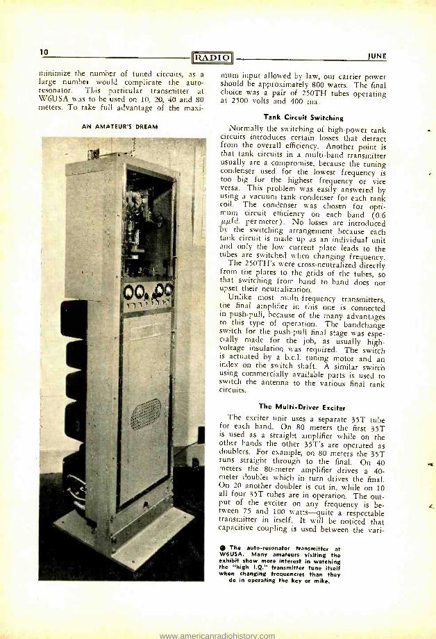
0 The auto- resonator transmitter at W6USA. Many amateurs visiting the exhibit show more interest in watching the "high I.Q." transmitter tune itself when changing frequencies than they
do in operating the key or mike.
www.americanradiohistory.com
12 RADIO
ous doubler stages, with inductive coupling used for the final amplifier grids. Inductive coupling was used in preference to capacitive coupling only because it was easier to balance the grid drive on the final. The exciter tubes operate with 1250 volts on their plates.
The Transmitter Control Unit
The control unit at the operating position uses a 6A6 (single section) as a Pierce oscil- lator in order to eliminate a tuned circuit at this point. The oscillator is followed by an 807. The plate circuit of the 807 is also kept at resonance by a tuning motor. The output of the control unit is always on the 80 -meter band. A variable- frequency electron - coupled oscillator could have been used in- stead of crystal control, but where persons unfamiliar with the use of such a device would be operating the transmitter, the use of crystal control was deemed advisable.
All in all twenty crystals are used in the control unit; the fundamental frequencies and harmonics of these crystals give a total of 60 operating frequencies on four bands: twenty on 80 meters, fourteen on 40 meters, eleven on 20 meters and fifteen on 10 meters. To simplify the use of the equipment to the greatest possible extent the 60 frequencies were actually engraved on a 71/2" celluloid composition dial which had been painted with black lacquer. The engraving penetrated the
JUNE
lacquer with the result that a panel light is clearly visible through the engraving. By placing colored cellophane behind the dial a very striking effect is produced.
As used at W6USA, four different colors are used to designate not only the different bands but whether the band in use is for class -A or class -B telephony. Green and blue designate "c.w. only," red is for "class -A phone," and yellow is "class -B phone." The contacts on the sixty -point switch are con- nected so that the proper exciter and final amplifier tank as well as the correct antenna are automatically connected for the desired band when that particular frequency appears on the dial.
For example, one frequency is 3502 kc. When this frequency appears on the dial the transmitter is automatically on the 80 -meter band. When the same crystal reappears on the dial as 7004 the transmitter is placed on 40 meters. The same takes places for 14,008 and 28,016 kc.
Aside from the large dial only four toggle switches are on the control unit. One lights the filaments of the control unit as well as those of the transmitter. A green pilot light tells the operator whether or not the filaments are lighted. A second switch turns on the power to the control unit as well as the trans- mitter. A red pilot light indicates when power is on. A third switch is for phone or c.w.;
10 METERC.iI TANK 4
20 METERS TANK I
40 METER ,-5 TANK -
- - - -J
0
!0 METER TANK ,
F
0
TUNING MOTOR
o
ANTENNA I
CHANGE -OVER
o
TO RECEIVER
TUNING MOTOR
10 X ANT.
20 X ANT.
40 X ANT
80 X ANT.
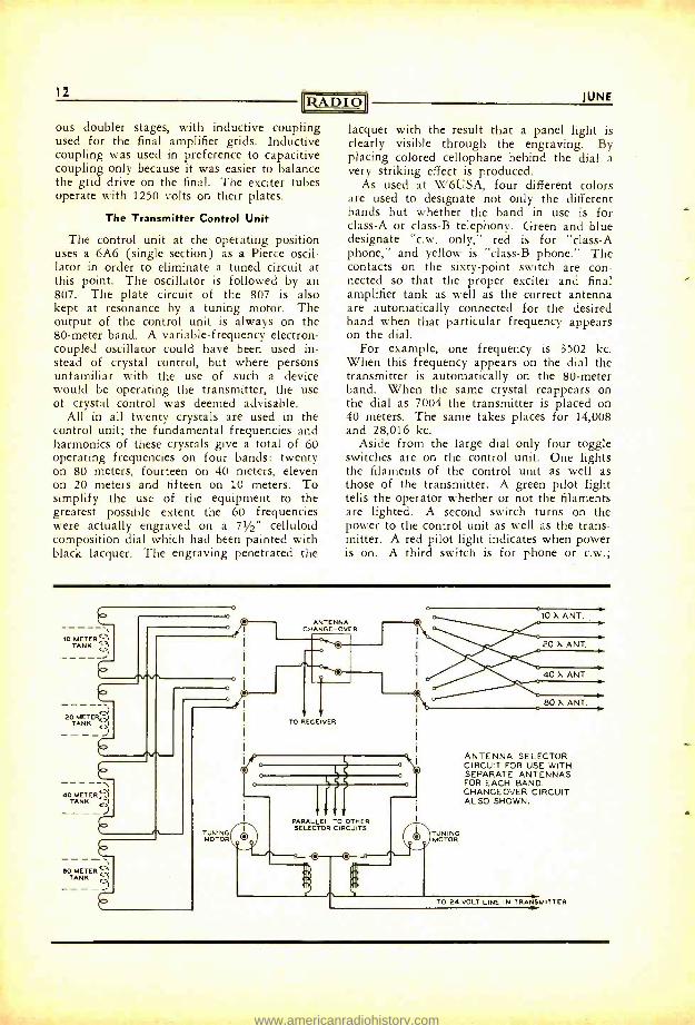
ANTENNA SELECTOR CIRCUIT FOR USE WITH SEPARATE ANTENNAS FOR EACH BAND. CHANGEOVER CIRCUIT ALSO SHOWN.
TO 24 VOLT LINE IN TRANSMITTER
b.
www.americanradiohistory.com
1939
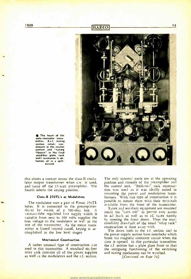
The heart of the auto -resonator trans- mitter. B.c.I. tuning motors rotate con- densers in the exciter portion and `tuning flippers" in the final amplifier plate tank until resonance is ob- tained, all in a split -
second.
13
this shorts a contact across the class -B modu- lator output transformer when c.w. is used, and turns off the 15 -watt preamplifier. The fourth selects the keying position.
Class -B 250TL's as Modulators
The modulator uses a pair of Eimac 250TL tubes. It is connected to the preamplifier - driver by means of a 500 -ohm line. A vacuum -tube regulated bias supply which is variable from zero to 300 volts supplies the bias voltage to the modulator as well as the rest of the transmitter. As the entire trans- mitter is biased beyond cutoff, keying is ac- complished in the low level stages.
Mechanical Construction
A rather unusual type of construction was used in this transmitter. A standard six -foot relay rack contains all of the power supplies as well as the modulators and the r.f. section.
The only external parts are at the operating position and consists of the preamplifier and the control unit. "Bath -tub" rack construc- tion was used as it was ideally suited to mounting the power and modulation trans- formers. With this type of construction it is possible to mount them with their terminals available from the front of the transmitter.
Tubes and auxiliary equipment are mounted inside the "bath tub" to permit easy access to all leads as well as to all tubes merely
by opening the front doors. Thus the inac- cessibility drawback of the usual "relay rack" construction is done away with.
The doors both to the r.f. section and to the power supply section have interlocks which break the magnetic contactor circuit when the door is opened. In this particular transmitter the r.f. section has a plate glass front so that the intriguing functioning of the switching and tuning mechanism can be watched.
[Continued on Page 74)
www.americanradiohistory.com
"HfC "1BflNSNIiifB GONTHRI. By CHARLES D. PERRINE, Jr.,
W6CUH
The e.c.o. situation needs no introduction - anyone in the last two dx contests knows the story of rotten notes, creeping signals, unread- able keying, and out -of -band birdies resulting from 99% of the e.c.o.'s. The fundamental e.c.o. circuit was not to blame; the fault lay with the method of its use. The only thought was of flexibility; all else seemed to be for- gotten as long as the oscillator covered the band. Though the bugs at the root of the trouble have turned out to be easily extermi- nated, the designs published in the past make only casual mention of one or two of these bugs and totally ignore the important ones. The writer's original e.c.o. was no exception, but its many afflictions led to a systematic investigation of just what it takes to make an e.c.o. tick.
The resulting unit has been termed a "Crys- tal E.C.O." because its performance rivals crystal control in every respect -this in actual tests at numerous other stations under various conditions of frequency, power, and line regu-
* Hughes Aircraft Co., Union Air Terminal, Burbank, Calif.
lation. The "XEC" oscillator by itself has a measured temperature coefficient of less than 10 cycles per megacycle per degree Centigrade, which is twice as good as the average X -cut crystal. Its voltage coefficient is less than one part in five million for a 10% plate voltage change. Boiled down, this means a normal drift at 14 Mc. of about 1 kc. from a cold start, and a 14 Mc. change of about 3 cycles for a 10% change in plate voltage as might be caused by keying a high power final. And, most important of all in e.c.o. practice, the circuit itself eliminates the principal path for the r.f. feedback that is sure to wreck the note when it gets into the oscillator.
The fundamental circuit is simple and in- volves no tricks. The several factors involving stability will be discussed, including the re- sults of tests made to determine the best oper- ating conditions. The practical application of these principles will be shown in an exciter unit used at W6CUH the past six months. Since it was built before some of the stabiliza- tion problems were worked out, this unit con- tains some extra precautions in the way of a neon -tube controlled voltage regulator and ad- ditional r.f. filtering to insure the desired re-
We have been long deluged with re- quests to describe a "good e.c.o." But after listening over the bands and ob- serving the nuisance that can be cre- ated by mediocre "band scooters," we decided that merely "good" was not good enough. Before an e.c.o. could be sanctioned by RADIO it would have to he the acme of perfection.
It was disconcerting to uncover what was apparently a "sweet smelling" e.c.o., then find that it could not be duplicated with the same results, or that it didn't perform the same with high power or on another rig.
"My friends tell me my e.c.o. sounds just like crystal and persuaded me to
.send in the enclosed article." So we would build up a duplicate to check the author's claims (no doubt made in good faith) before running the article. In- variably when the finished model was used on c.w. with a high -power final amplifier the note would sound like either the fourth harmonic of an image of a ghost signal or else a T -1 parasitic afflicted with delirium tremens.
But at last we can offer an e.c.o. ex- citer that is as outstandingly good as the average one is bad. It has passed every conceivable test with flying colors, and you can build one with the assur- ance that it will be difficult to tell your note from crystal control. -THE EDITOR.
14
www.americanradiohistory.com
NEW D E S I G N P R I N C I P L E S I N
A FOOL -PROOF E.C.O.
sults. If built complete as shown, crystal re- sults from the XEC are to be anticipated under all conditions.
E.C.O. Considerations
Poor e.c.o. operation results from four things: r.f. feedback, plate voltage changes, temperature changes, and mechanical vibra- tion. They are listed in order of importance. Remove the effects of these factors and the frequency is immediately nailed down, elimi- nating the frequency modulation and drift that are normally multiplied several times in reach- ing one of the higher frequency bands.
There are two obvious ways of attaining stability: one is to isolate the oscillator from these disturbances, the other is to make the oscillator itself immune to outside effects. A combination of the two has been used in the new exciter. R.f. feedback is prevented by feeding the XEC tube heater through the coil, with isolation provided by an r.f. filter in the power leads. Correctly adjusted XEC grid ex- citation and a new method of obtaining screen voltage result in immunity to plate voltage changes, with the voltage regulator added for isolation. Temperature isolation is a difficult job; therefore temperature immunity is relied upon. It is obtained by using one of the new ceramic negative -coefficient condensers for tem- perature compensation. Lastly, mechanical vi- bration is reduced by isolation and correct mounting of parts.
Referring to the main circuit diagram, we see that the XEC is fundamentally a standard electron -coupled oscillator working on 1.75 Mc. It is impedance coupled to a 6V6 doubler-
- crystal oscillator on 3.5 Mc. The output stage uses an RK39 or 807 doubling to 7 Mc. with a measured output of 20 watts. Any further frequency multiplication is done in the trans- mitter itself. The XEC oscillator section must operate on 1.75 Mc., as operation on the same band as any other stage in the exciter imme- diately causes instability.
The 6SK7 was chosen for the oscillator tube after a large number of tests with differ-
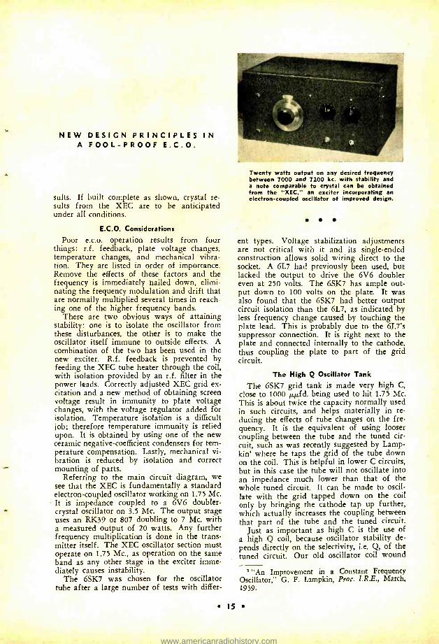
Twenty watts output on any desired frequency between 7000 and 7200 kc. with stability and a note comparable to crystal can be obtained from the "XEC," an exciter incorporating an electron- coupled oscillator of improved design.
ent types. Voltage stabilization adjustments are not critical with it and its single -ended construction allows solid wiring direct to the socket. A 6L7 had previously been used, but lacked the output to drive the 6V6 doubler even at 250 volts. The 6SK7 has ample out- put down to 100 volts on the plate. It was also found that the 6SK7 had better output circuit isolation than the 6L7, as indicated by less frequency change caused by touching the plate lead. This is probably due to the 6L7's suppressor connection. It is right next to the plate and connected internally to the cathode, thus coupling the plate to part of the grid circuit.
The High Q Oscillator Tank
The 6SK7 grid tank is made very high C, close to 1000 µµfd. being used to hit 1.75 Mc. This is about twice the capacity normally used in such circuits, and helps materially in re- ducing the effects of tube changes on the fre- quency. It is the equivalent of using looser coupling between the tube and the tuned cir- cuit, such as was recently suggested by Lamp - kin' where he taps the grid of the tube down on the coil. This is helpful in lower C circuits, but in this case the tube will not oscillate into an impedance much lower than that of the whole tuned circuit. It can be made to oscil- late with the grid tapped down on the coil only by bringing the cathode tap up further, which actually increases the coupling between that part of the tube and the tuned circuit.
Just as important as high C is the use of a high Q coil, because oscillator stability de- pends directly on the selectivity, i.e. Q, of the tuned circuit. Our old oscillator coil wound
"An Improvement in a Constant Frequency Oscillator," G. F. Lampkin, Prot. I.R.E., March, 1939.
15
www.americanradiohistory.com
16 IUNE
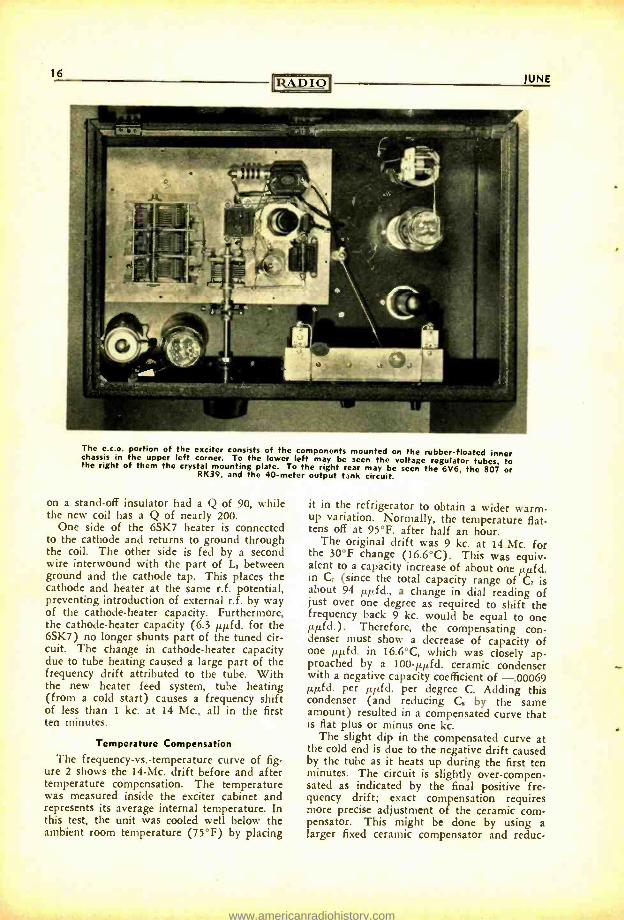
The e.c.o. portion of the exciter consists of the components mounted on the rubber -floated inner chassis in the upper left corner. To the lower left may be seen the voltage regulator tubes, to the right of them the crystal mounting plate. To the right rear may be seen the 6V6, the 807 or RK39, and the 40 -meter output tank circuit.
on a stand -off insulator had a Q of 90, while the new coil has a Q of nearly 200.
One side of the 6SK7 heater is connected to the cathode and returns to ground through the coil. The other side is fed by a second wire interwound with the part of L1 between ground and the cathode tap. This places the cathode and heater at the same r.f. potential, preventing introduction of external r.f. by way of the cathode- heater capacity. Furthermore, the cathode -heater capacity (6.3 µµfd. for the 6SK7) no longer shunts part of the tuned cir- cuit. The change in cathode- heater capacity due to tube heating caused a large part of the frequency drift attributed to the tube. With the new heater feed system, tube heating (from a cold start) causes a frequency shift of less than 1 kc. at 14 Mc., all in the first ten minutes.
Temperature Compensation
The frequency -vs.- temperature curve of fig- ure 2 shows the 14 -Mc. drift before and after temperature compensation. The temperature was measured inside the exciter cabinet and represents its average internal temperature. In this test, the unit was cooled well below the ambient room temperature (75 °F) by placing
it in the refrigerator to obtain a wider warm - up variation. Normally, the temperature flat- tens off at 95 °F. after half an hour.
The original drift was 9 kc. at 14 Mc. for the 30 °F change (16.6 °C). This was equiv- alent to a capacity increase of about one µµtd. in Cr (since the total capacity range of C. is about 94 µµfd., a change in dial reading of just over one degree as required to shift the frequency back 9 kc. would be equal to one µµfd.). Therefore, the compensating con- denser must show a decrease of capacity of one µµfd. in 16.6 °C, which was closely ap- proached by a 100 -µµfd. ceramic condenser with a negative capacity coefficient of -.00069 µµfd. per µµfd. per degree C. Adding this condenser (and reducing C. by the same amount) resulted in a compensated curve that is flat plus or minus one kc.
The slight dip in the compensated curve at the cold end is due to the negative drift caused by the tube as it heats up during the first ten minutes. The circuit is slightly over- compen- sated as indicated by the final positive fre- quency drift; exact compensation requires more precise adjustment of the ceramic com- pensator. This might be done by using a larger fixed ceramic compensator and reduc-
www.americanradiohistory.com
Alb
1939 RADIO 17
HIP E.C.O.
Rio
Ri3 RCA 991
C
2A3
CI1
Figure 1.
SZ
03V. FROM T2
807 opt RK39
E ° ¡COUPIiNG C10 O 10`-}(C)')TO CONCEN-
TRIC LINE rA La
R7
tIC33
HEATERS X X
6SY K7 HEATER
RFC,
1 1 t C3 C3 500 V
POWER SOCKET
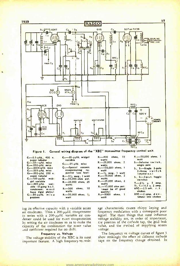
General wiring diagram of the "XEC" transmitter frequency control unit.
C -0.1 -pfd., 400 v. paper tubular
C: -.01 -1.ifd. mica Ca- .002 -pfd. mica C4- .0001 -1.1.fd. mica Cr,- .001 -pfd. mica Co- .002 -pfd. 200 v.
paper tubular Ca- 100 -ppfd. mid-
get variable C, -.001 -pfd. vari-
able (3 -gang b.c.1. condenser; must have rigid plates)
C .-30 -110d. m i c a
padders
C,,-35 -1.1.pfd. midget variable
C11-.01 -pfd. mica
C, Special ceramic compensating ca- pacitor (see text)
R1-11/2 meg., 1 watt R.- 50,000 -ohm pot. R,- 20,000 ohms, 25
watts R, -500 ohms, 10
watts R:. 50,000 ohms, 1/2
watt
R ).-400 ohms, 10 watts
R,- 20,000 ohms, 2 watts
R,- 150,000 ohms, 1
watt R -1/2 meg., 1 watt R ,- 10,000 ohms, 2
watts R1)- 25,000 ohms, 2
watts Ru- 15,000 ohm pot.
(must be of good quality)
R, -5000 ohms, 1
watt
Rn- 50,000 ohms, 1
watt S,- Selector switch,
single pole S , S;- Single 3 -pole
2 -throw s w i t c h
(crystal -e.c.) 5,, 5:.- S.ps.t, toggle
switches T, -21/2 v. 3 amp.
T: -6.3 v. 2 amp. RFC,- 2.5 -mh. r . f .
chokes RFC. -2 -amp. d u o -
lateral line chokes
ing its effective capacity with a variable series air condenser. Thus a 200 -µµfd. compensator in series with a 200 -µµfd. variable air con- denser could be used for exact compensation by setting the air condenser so as to make the capacity of the combination the exact value and coefficient required for no drift.
Frequency vs. Voltage The voltage stability of the XEC is its most
important feature. A high frequency -vs. -volt-
age characteristic causes chirpy keying and frequency modulation with a consequent poor signal. The three things that most influence voltage stability are, in order of importance, the position of the cathode tap, the grid leak value, and the method of supplying screen voltage.
The frequency -vs.- voltage curves of figure 3
show strikingly the effect of different cathode taps on the frequency change obtained. In
www.americanradiohistory.com
18 D O
these tests the screen voltage came directly from the voltage divider with R. set at zero and the tap on Ra half way down. With the cathode tap two turns up from the ground end of L, (K =2), the frequency of the eighth harmonic on 14 Mc. increases 2 kc. when the plate voltage is doubled from 150 to 300 volts. At turn 5 the frequency starts to increase with the plate voltage, then drops back near the 300 -volt point. With the tap farther up the coil (K =6 and 7), the frequency decreases with the plate voltage. Thus a definite point can be found for the cathode tap at which the frequency will remain almost constant over a wide voltage range.
The foregoing tests were run with a 11/2- megohm grid leak as specified in figure 1. Substituting the commonly used values of 50,- 000 or 100,000 ohms just about doubled the frequency change in each case. The highest value of leak that can be used without block- ing is theoretically the best. In this case, little improvement was noted with values above 11 /2 megohms, and as the output of the oscillator drops with these higher values, 11 /2 megohms was taken as the optimum resistance.
Screen Voltage
Correct adjustment of the screen voltage is the last step in the process of voltage stabili- zation. Unless the cathode tap and grid leak are already set correctly, variation of the screen voltage has no appreciable effect on the voltage characteristic of the oscillator. The usual method of obtaining screen voltage from a voltage divider is only partly effective by comparison with the combination of series screen resistor and divider as shown in figure 1. The voltage at the divider tap should be about 85% of the plate voltage, and that on the screen about 70% of the plate voltage as measured on a high resistance voltmeter. The plate voltage used on the 6SK7 is 200 volts, divider tap 170 volts, and screen 140 volts. It should be pointed out here that the screen
COIL TABLE
L -20 turns no. 26 enam. 1 in. dia., spaced to 3á in., tapped at 5th turn from ground.
L -5 turns no. 26 enam. interwound below cathode tap on L,.
L-48 turns no. 26 enam. close wound, 1 !/a in. dia.
L -23 turns no. 24 enam. 11/2 in. dia., spaced to 11/2 in.
L -Two turn link at cold end of L.
JUNE
voltage as determined by R. and R. must vary with the plate voltage. Any independent sta- bilization of the screen voltage alone by means of a gaseous regulator tube will increase the frequency shift.
The curve of figure 4 shows the results of final adjustments on the cathode tap, grid lead, and screen resistor network. The fre- quency variation is given in cycles at 14 Mc.; the change would be twice as great on the 28 -Mc. band, on the 7 Mc. one half. This means the maximum change in fundamental oscillator frequency is about eight cycles for a plate voltage variation from 150 to 200 volts. The dotted curve of figure 4 shows the frequency change of the 6V6 crystal oscillator over the same plate voltage range. A compari- son of the curves indicates that operation of the XEC on the flat portion of its curve (be- tween 200 and 250 volts) will give better stability than the crystal for changes up to 15%. However, rapid changes in plate volt- age, such as power supply ripple, have more effect on the XEC than on the crystal because the latter can compensate faster; therefore, plenty of filter is still required in the power supply. Line voltage changes reaching the XEC due to keying are slowed down by the power supply filter and do not bother the XEC (this with the tube voltage regulator cut out).
The 6V6 Doubler -Oscillator
The plate of the 6SK7 is loosely coupled through C, to the grid of the 6V6 3.5 -Mc. doubler. One section of the three -section switch, S,, transfers the grid of the 6V6 to the crystal selector switch, S,. The second section of S. removes screen voltage from the XEC when crystal control is being used; there is no tube drift, hence no reason to leave the XEC running during stand -by periods with the attendant chance of mixing some of its output with that of the crystal and landing a "birdie" out of the band. The third section of S. shifts from green to red pilot lights when going to XEC operation, as additional warning to be sure of the XEC frequency be- fore going on the air.
The 6V6 3.5 -Mc. doubler -oscillator is con- ventional. Its plate coil, La, is cut to resonate just above the highest crystal frequency used, which is 3600 kc. Sufficiently constant excita- tion is thus supplied the 7 -Mc. doubler over the whole range from 3500 to 3650 kc., either crystal for XEC. Only two crystals are now used, one 3500 kc. and the other 3600 kc., as the XEC handles all in -band work. The crys- tals are of the low drift type and are set the desired number of cycles inside the band edges
www.americanradiohistory.com
1939 RADIO 19
,...-+I
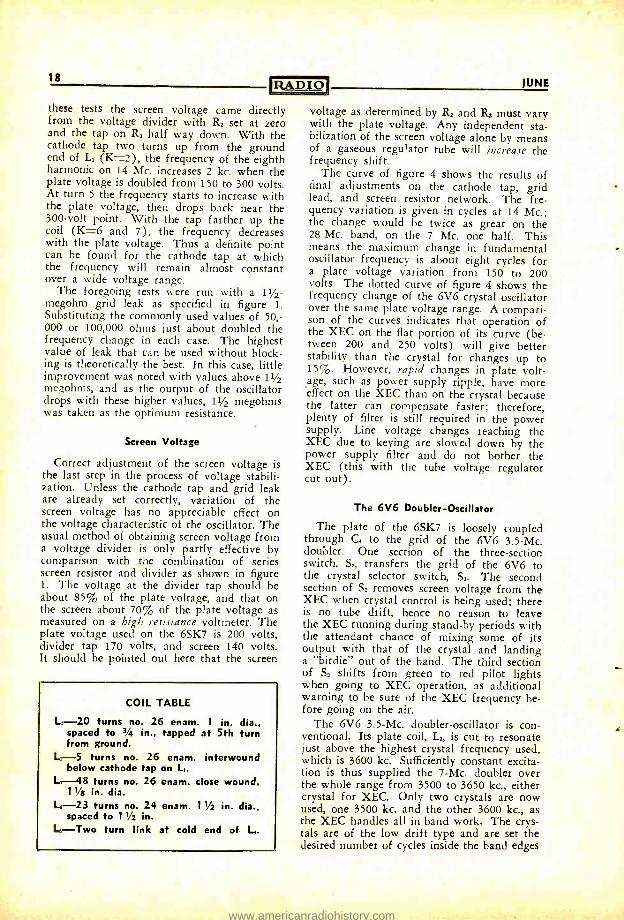
The line chokes may be seen in the upper right corner, the voltage regulator components to the lower right. The 6V6 plate coil is to the right of the two isolantite sockets.
by condensers C9. The resistors R4 maintain the crystal temperature well above the am- bient, greatly reducing the effects of crystal current and the room temperature variation on the temperature of the crystals.
The Output Stage The RK39 or 807 works into a rather low
C plate tank which, when properly loaded, tunes broadly enough to cover the whole 7- Mc. band fix -tuned. Its measured output varies between 17 and 20 watts over the band.
The Voltage Regulator
The voltage regulator is of the familiar type using a 2A3 and 6C6 with an RCA991 neon tube. The condenser C. from the 6C6 grid to ground was added to preclude any change of r.f. feedback to the grid, which in a former regulator made the regulation of the supply worse than it had been with no regula- tor! Oscillation of the neon tube is prevented by the condenser Cn and the damping re- sistor R,,. Neon tube oscillation, if not thus dampened, will be about 30 kc. and will mix with the XEC output to give birdies 30 kc. each side of the main wave.
As stated previously in this article, such as elaborate voltage regulator was built in before
the voltage stabilization of the oscillator had been perfected. In view of the excellent sta- bility subsequently realized in the XEC, a sim- ple gaseous type of regulator is all that would ever be needed. A VR150 regulator can be used by inserting a 5000 -ohm, 25 -watt resistor to drop the 500 -volt supply voltage to 150 volts for the 6SK7 and 6V6, the VR150 being connected from the 150 -volt end of the drop- ping resistor to ground. In the regulator shown, L. is set for an output voltage of 200, but 150 volts is still sufficient from the stand- point of output.
Extra r.f. isolation is supplied by r.f. chokes in the 500 -volt line and the 110 -volt line. Each r.f. choke is by- passed to ground on both sides. Two switches are shown in the 110 - volt line. S. cuts in just the 6SK7 and crystal heaters and is usually left on 24 hours a day. S, turns on the other tubes when actual trans- mission is contemplated.
Construction
Now we come to the constructional part of the story, of which the most important points concern the XEC. The entire exciter is housed in a standard receiver cabinet. The photo- graphs and their accompanying captions are almost self -explanatory as far as the layout
www.americanradiohistory.com
20 RA D I 01
rTEF 'NEEMIZINii
hilWt)c
eo 70 e0 TEMPERATURE. DEGREES FAHR.
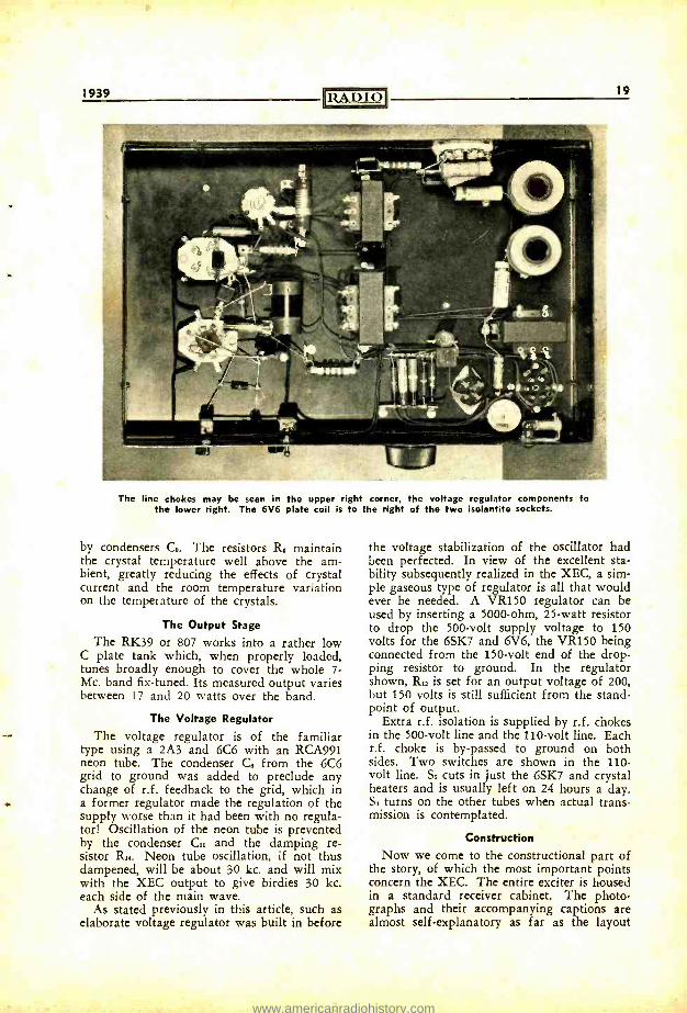
Figure 2. Showing improvement in tempera- ture stability obtained with ceramic compen- sating capacitor of correct value and coeffi- cient. Temperature readings were taken in- side cabinet over a period of approximately one hour after unit was first cooled in a
refrigerator.
90.
is concerned. Only two parts need to be treated in detail: the e.c.o. unit and the mount- ing for the crystals.
The e.c.o. unit is a complete, self- contained sub -assembly. All parts are bolted solidly to 7" x 9" dural plate 3/16" thick to prevent any movement or vibration with respect to one another. A common error in e.c.o. con- struction is to mount the part solidly enough, but to different parts of the cabinet such as the panel, chassis, and sides. With such con- struction any strain on the box will be sure to change the frequency. The durai plate just referred to is mounted on the regular chassis of the receiver cabinet with three rub- ber shock -absorbing supports such as are used in the better b.c.l. receivers to support tuning assemblies. These supports resemble large grommets and are easily mounted with one screw each. Three -point suspension is used so
-2000
R- C-
-1000
K=3
K=4
.K_5
K=0
K=7 -1000
-2f If
Es0 KEPT AT i Ep WITH R2'o
150 200 250 300 E.C.O. PLATE VOLTAGE
Figure 3. Illustrating importance of correct cathode tap. These curves were obtained with-
out series resistance in the screen circuit.
that deformations of the main chassis will not transmit strains to the durai plate. Two flexible couplings are used between the tun- ing condenser, C,, and the main dial. And since all leads to the e.c.o. are made with flexible wire, little or no outside vibration can reach the oscillator.
Looking at the top view of the exciter, the large tank capacitor, C,, can be seen at the left end of the e.c.o. unit. In the lower center is the tuning condenser G. The 6SK7 is at the right end of the unit, its socket set up from the base plate on 3/4" spacers. Just above the tube is the coupling condenser, C. mounted on two 3/4" standoff insulators. To the left of the tube are the plate and screen by- passes, C5 and C2, bolted one over the other to the durai. Below the tube is the coil, L,, wound on a National XR -2 form screwed directly to the base. Just to the left of the coil is the little ceramic compensating condenser amply supported by its leads; it looks very much like a half -watt resistor. The compensator is mounted close to the coil so that it will follow the temperature variations
100
V
0 50
/-
+I N o
w
ú r u 50
150 200 250 PLATE VOLTS
E.C.O.
300
Figure 4. Over the flat portion of the curve the final version of the "XEC" shows better voltage -vs.- frequency characteristics than a
crystal oscillator.
e o
of the latter, for it is the coil which causes 90% of the frequency change with tempera- ture. Just to the right of the coil is the grid condenser firmly screwed to the base. A heavy, cadmium -plated steel shield can bolts directly to the edges of the dural plate, covering the whole XEC. This shield eliminates any effect on frequency of stray capacities in the box, but is not essential except as a refinement.
Also seen in the top view is the common bottom plate for the crystals. The plate is made of quarter -inch aluminum for good heat conductivity. It is mounted on the front panel directly above the switches Si and S2. The crystal setting condensers, Co, are attached to the back edge of the plate near each end. The crystals (not shown) rest freely on the bottom plate; the two top plates can be seen
[Continued on Page 751
www.americanradiohistory.com
34'
I
tt6 9'
WOODEN SPREADERS
Cfp-. -- I t-
6 9"-¡ INSULATORS 24 6
600 OHM LINE ANY LENGTH
49 6
24.6..__ _--i
JUMPER FOR 2ND HARMONIC
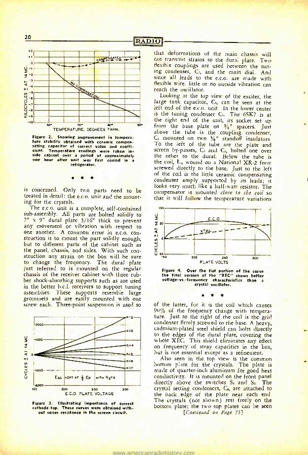
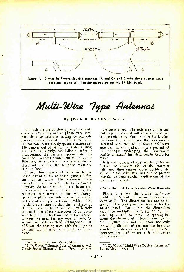
Figure 1. 2 -wire half -wave doublet antennas (A and C( and 2 -wire three -quarter wave doublets I B and D(. The dimensions are for the 14-Mc. band.
Mu&-We Type 44e#uiat By JOHN D. KRAUS, W8JK
Through the use of closely- spaced elements operated essentially out of phase, very corn- pact directive antennas having considerable gain can be constructed. In the flat -top beam the currents in the closely- spaced elements are 180 degrees out of phase. In systems using a radiator and closely- spaced director- reflector arrangement, the currents approximate this condition. As was pointed out in RADIO for February,' it is generally a characteristic of these antennas that the radiation resistance is quite low.
If two closely- spaced elements are fed in phase instead of out of phase, quite a differ- ent situation results. The resistance at the current loop is increased. The two elements, however, do not function like a beam sys- tem as when fed out of phase. Rather, the radiation characteristics of the two closely - spaced in -phase elements are much similar to those of a simple half -wave doublet. The outstanding change is that the resistance at the feed point may be increased sufficiently to permit the direct connection of an open -
wire type of transmission line to the antenna without the need for any type of stub, Q- section, or delta- matching arrangement. In addition, the spacing used with the in -phase elements can be made very small, or ultra - close.
* Arlington Blvd., Ann Arbor, Mich. ' J. D. Kraus, "Characteristics of Antennas with
Closely- Spaced Elements," RADIO, Feb., 1939, p. 9.
To summarize: The resistance at the cur- rent loop is decreased with closely- spaced out - of -phase elements. On the other hand, when the elements are in phase, the resistance is increased over that for a simple half -wave antenna. This, in effect, is a statement of the principle underlying the "multi -wire doublet antennas" first described in RADIO for May.'
It is the purpose of this article to discuss further the characteristics of the two -wire half and three -quarter wave doublets de- scribed in the May issue and also to present material on some further applications of the multi -wire principle.
2 -Wire Half and Three -Quarter Wave Doublets
Figure 1 shows the 2 -wire half -wave doublet at A and the 2 -wire three -quarter wave at B. The dimensions are not at all critical. The ones given are suitable for the 14 -Mc. band. For 7 Mc. the dimensions should be multiplied by 2, for 28 Mc. di- vided by 2, and so forth. A spacing be- tween the elements of 1 foot is used on 14 Mc. Figures 1 -A and 1 -B show not only the wiring diagram of the antennas but also a suitable construction in which short wooden spreaders are used at the ends and center of the antennas.
' J. D. Kraus, "Multi -Wire Doublet Antennas," RADIO, May, 1939, p. 24.
21
www.americanradiohistory.com
22
-_ ----- - _ --I O -1
3/4
[RADIO
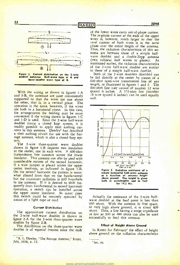
Figure 2. Current distribution on the 2 -wire doublet antennas. Half -wave type at A and
three -quarter wave type at B.
With the wiring as shown in figures 1 -A and 1 -B, the antennas are most conveniently supported so that the wires are one above the other, that is, in a vertical plane. The operation is the same, however, if the wires are both in a horizontal plane. In this case, the arrangements for feeding may be more convenient if the wiring shown in figures 1 -C and 1 -D is used. Since the 2 -wire half -wave doublet forms a closed loop system, it is readily possible to apply sleet melting cur- rents to this antenna. Dawley' has described a sleet melting circuit for use with the bar- rage antenna, which is also a closed loop sys- tem.
The 2 -wire three -quarter wave doublet shown in figure 1 -B requires two insulators at the center, one in each wire. A 600 -ohm transmission line connects across the lower insulator. This antenna can also be used with considerable success of the second harmonic, if a wire jumper is placed across the upper center insulator, as indicated in figure 1 -B. On the second harmonic the pattern is some- what altered from that on the fundamental but the maximum radiation is still broadside to the antenna. If it is desired to shift fre- quently from fundamental to second harmonic operation, a switch can be installed across the upper center insulator. In many cases this switch could be remotely operated by means of a light rope or cord.
Current Distribution The approximate current distribution on
the 2 -wire half -wave doublet is shown in figure 2 -A for the 2 -wire three -quarter wave doublet by figure 2 -B.
The distribution on the three -quarter wave doublet is of especial interest since the ends
' R. L. Dawley, "The Barrage Antenna," RADIO, July, 1938, p. 12.
JUNE
of the lower wires carry out -of -phase current. The in -phase current at the ends of the upper wires is, however, much larger so that the total current of both wires is in the same phase over the entire length of the antenna. Thus, the radiation characteristics of this an- tenna are between those of a simple half - wave doublet and a double -Zepp antenna (two colinear half waves in phase). As mentioned earlier, the radiation characteristics of the 2 -wire half -wave doublet are similar to those of a simple half -wave doublet.
Both of the 2 -wire doublets described can be fed directly at the center by means of a 600 -ohm open -wire transmission line of any length, as illustrated in figures 1 and 2. The 600 -ohm line may consist of number 12 wire spaced 6 inches. A 572 -ohm line (number 10 wire spaced 6 inches) can be used equally well.
100
60
co 73
x o 60
w O
40
Vl w ¢ 20
o o
HEIGHT IN WAVELENGTHS 02 04 06 06 10
I I I I 0 10 20 30 40 50
HEIGHT IN FEET FOR 14.2 MC.
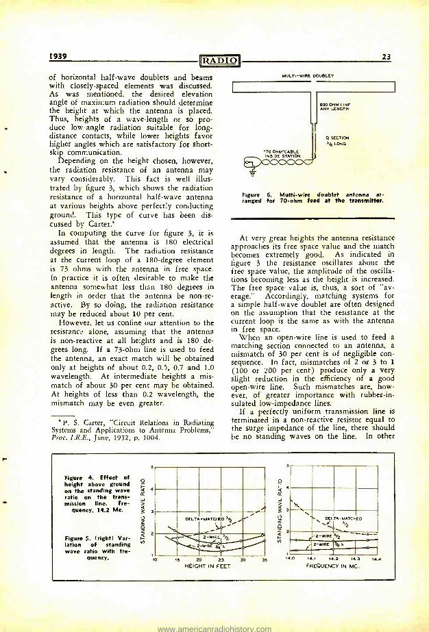
Figure 3. Radiation resistance of a simple horizontal half -wave antenna as a function of antenna height above ground. The height is given both in wavelengths and in feet
for 14.2 Mc.
60 70
Actually the resistance of the 2 -wire half - wave doublet at the feed point is less than 600 ohms. With the antenna in free space, or very high above ground, it is about 400 ohms. Thus, a line having a surge impedance as low as 300 or 400 ohms can also be used successfully to feed this antenna.
Effect of Height Above Ground
In RADIO for February' the effect of height above ground on the radiation characteristics
' loc. cit.
www.americanradiohistory.com
1939 RADIO
of horizontal half -wave doublets and beams with closely- spaced elements was discussed. As was mentioned, the desired elevation angle of maximum radiation should determine the height at which the antenna is placed. Thus, heights of a wave -length or so pro- duce low -angle radiation suitable for long - distance contacts, while lower heights favor higher angles which are satisfactory for short - skip communication.
Depending on the height chosen, however, the radiation resistance of an antenna may vary considerably. This fact is well illus- trated by figure 3, which shows the radiation resistance of a horizontal half -wave antenna at various heights above perfectly conducting ground. This type of curve has been dis- cussed by Carter'
In computing the curve for figure 3, it is assumed that the antenna is 180 electrical degrees in length. The radiation resistance at the current loop of a 180- degree element is 73 ohms with the antenna in free space. In practice it is often desirable to make the antenna somewhat less than 180 degrees in length in order that the antenna be non -re- active. By so doing, the radiation resistance may be reduced about 10 per cent.
However, let us confine our attention to the resistance alone, assuming that the antenna is non -reactive at all heights and is 180 de- grees long. If a 73 -ohm line is used to feed the antenna, an exact match will be obtained only at heights of about 0.2, 0.5, 0.7 and 1.0 wavelength. At intermediate heights a mis- match of about 30 per cent may be obtained. At heights of less than 0.2 wavelength, the mismatch may be even greater.
P. S. Carter, "Circuit Relations in Radiating Systems and Applications to Antenna Problems," Proc. I.R.E., June, 1932, p. 1004.
23
MULTI -WIRE DOUBLET
600 OHM LINE ANY LENGTH
O SECTION
X4 LONG
070 OHM -CABLE ^^`` INSIDE STATION
1/4
Figure 6. Multi -wire doublet antenna ar- ranged for 70 -ohm feed at the transmitter.
At very great heights the antenna resistance approaches its free space value and the match becomes extremely good. As indicated in figure 3 the resistance oscillates about the free space value, the amplitude of the oscilla- tions becoming less as the height is increased. The free space value is, thus, a sort of "av- erage." Accordingly, matching systems for a simple half -wave doublet are often designed on the assumption that the resistance at the current loop is the same as with the antenna in free space.
When an open -wire line is used to feed a matching section connected to an antenna, a mismatch of 30 per cent is of negligible con- sequence. In fact, mismatches of 2 or 3 to 1
(100 or 200 per cent) produce only a very slight reduction in the efficiency of a good open -wire line. Such mismatches are, how- ever, of greater importance with rubber -in- sulated low- impedance lines.
If a perfectly uniform transmission line is terminated in a non -reactive resistor equal to the surge impedance of the line, there should be no standing waves on the line. In other
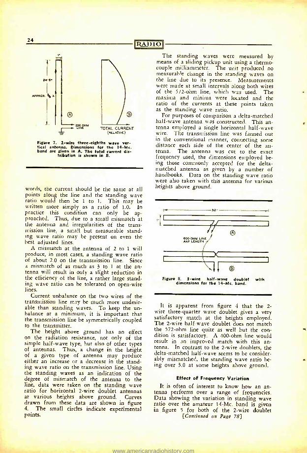
Figure 4. Effect of height above ground on the standing wave ratio on the trans- mission line. Fre-
quency, 14.2 Mc.
Figure 5. (right) Var- iation of standing wave ratio with fre-
quency.
4
3
2
P
10
DELTA -MATCHED i0".
15 20 25 30 HEIGHT IN FEET
35
o
4 o' W
3
O 2
Ñ
O N. \ DELTA- MATCHED
2 -WIRE ,Y2
,( 2 -WIRE 0 I4 X.
14.1 14.2 14.3
FREQUENCY IN MC.
144
www.americanradiohistory.com
24
2.. 6.
APPRO% 343 A
250 OHM LINE TOTAL CURRENT
(RELATIVE)
Figure 7. 2 -wire three -eighths wave ver- tical antenna. Dimensions for the 14 -Mc. band are given in A. The total current dis-
tribution is shown in B.
RADIO
words, the current should be the same at all points along the line and the standing wave ratio would then be 1 to 1. This may be written more simply as a ratio of 1.0. In practice this condition can only be ap- proached. Thus, due to a small mismatch at the antenna and irregularities of the trans- mission line, a small but measurable stand- ing wave ratio may be present on even the best adjusted lines.
A mismatch at the antenna of 2 to 1 will produce, in most cases, a standing wave ratio of about 2.0 on the transmission line. Since a mismatch of as much as 3 to 1 at the an- tenna will result in only a slight reduction in the efficiency of the line, a rather large stand- ing wave ratio can be tolerated on open -wire lines.
Current unbalance on the two wires of the transmission line may be much more undesir- able than standing waves. To keep the un- balance at a minimum, it is important that the transmission line be symmetrically coupled to the transmitter.
The height above ground has an effect on the radiation resistance, not only of the simple half -wave type, but also of other types of antennas. Thus, a change in the height of a given type of antenna may produce either an increase or a decrease in the stand- ing wave ratio on the transmission line. Using the standing waves as an indication of the degree of mismatch of the antenna to the line, data were taken on the standing wave ratio for horizontal 2 -wire doublet antennas at various heights above ground. Curves drawn from these data are shown in figure 4. The small circles indicate experimental points.
The standing waves were measured by means of a sliding pickup unit using a thermo- couple milliammeter. The unit produced no measurable change in the standing waves on the line due to its presence. Measurements were made at small intervals along both wires of the 572 -ohm line, which was used. The maxima and minima were located and the ratio of the currents at these points taken as the standing wave ratio.
For purposes of comparison a delta -matched half -wave antenna was constructed. This an- tenna employed a single horizontal half -wave wire. The transmission line was fanned out in the conventional manner, connecting some distance each side of the center of the an- tenna. The antenna was cut to the exact frequency used, the dimensions employed be- ing those commonly accepted for the delta - matched antenna as given by a number of handbooks. Data on the standing wave ratio were also taken with this antenna for various heights above ground.
32
,T t 77-1
600 OHM LINE ANY LENGTH
Figure 8. 3 -wire half -wave doublet with dimensions for the 14 -Mc. band.
It is apparent from figure 4 that the 2- wire three -quarter wave doublet gives a very satisfactory match at the heights employed. The 2 -wire half -wave doublet does not match the 572 -ohm line quite as well but the con- dition is satisfactory. A 400 -ohm line would result in an improved match with this an- tenna. In contrast to the 2 -wire doublets, the delta- matched half -wave seems to be consider- ably mismatched, the standing wave ratio be- ing over 3.0 at some heights above ground.
Effect of Frequency Variation
It is often of interest to know how an an- tenna performs over a range of frequencies. Data showing the variation in standing wave ratio over the amateur 14 -Mc. band is given in figure 5 for both of the 2 -wire doublet
[Continued on Page 78}
www.americanradiohistory.com
r
M ION
By CHARLES R. LEUTZ
Every once in a while some amateur la- ments the fact that he has spent a lot of time and money on amateur radio and has nothing to "show" for his efforts. During the past twenty years or more the writer has observed the progress of hundreds of amateurs. Some of these young men made the most out of radio opportunities that came up; others did not.
Some people will argue that an amateur is just an amateur and that amateur radio activities should be regarded simply as a hobby. It is true that many men, well estab- lished in some other line of business, do find radio an interesting diversion and excellent hobby. However, the young amateur in high school, ce i{ege, or who has even started to work in some field other than radio, should give serious thought to the opportunities offered in the radio and allied fields.
Years ago the future of radio was so un- certain that it was very difficult for an amateur to decide what course to pursue. Today, any amateur who wants to make a future out of radio can map out a definite program. There are many ways in which an amateur can make his hobby pay as it goes along and also contribute experience of value.
It is best to decide as early as possible just what, if anything, you want to do in radio, that is, whether you want to be a commercial radio operator, a radio executive, a radio engineer, etc.
Assuming an amateur intends to become an engineer, then a university education and degree are essential. Among some of the lead- ing radio engineers and executives active to- day there are a few who are not college graduates. However, these top executives who are not college graduates usually follow a strict policy of hiring only graduate engineers. Times have changed; years ago experience in radio counted more than education. Today it is exactly the opposite; advanced education is necessary to grasp quickly a summary of the past experiences of the pioneers. In the old days a radio engineer was expected to design transmitters, receivers, antennas,
* 9015 Myrtle Ave., Glendale, L. I., N. Y.
towers, power plants and even buildings. To- day, all these individual branches have be- come so far developed that engineers must specialize on some one subject, or even a sub- division of one subject.
The matter of a college degree cannot be over emphasized. It is essential in order to qualify for many worth -while City, State or Federal Civil Service positions. With few exceptions, industrial employment managers prefer graduate engineers of little experience to non -graduates with long experience. The reason is sound, as the well- educated engineer can adapt himself quickly to new problems. He has the foundation to work out a prob- lem without depending upon precedent.
If the prospective radio engineer cannot afford a college education, there are alterna- tives. Thousands of scholarships are avail- able from universities in every state. Many cities have colleges providing engineering courses to residents living in the city one year or more. Another alternative is to work in the daytime and take a night course which leads to a college degree in six years.
There are a few commercial radio schools which are accredited and have an excellent reputation. However, there are also dozens which specialize only in taking your money. Before enrolling in one of these private radio schools one should investigate thoroughly, and not put too much stock in their claims without first checking up to see how the graduates fare when it comes to getting jobs. The schools referred to are the resident schools. Most of these schools also offer home study courses, which undoubtedly are a means for advancement but are not nearly so effective as the resident course, where the student attends class and has the benefit of lectures, individual instruction, and more ex- tensive equipment.
Amateur radio activities carried on during high school and college terms need not in- terfere with studies. As a matter of fact, one can supplement the other in several ways. The smart amateur is not satisfied with a mere ham ticket. He obtains, as early as possible, a commercial radio operator's license.
[Continued on Page 89]
25
www.americanradiohistory.com
Qettü.y ßae ¡a4
HUTOMHTI MOOUHIIHN ONTHU l By FRANK C. IONES, W6AIF
A simplified scheme of getting bias for a.m.c., automatic modulation control, is shown in the circuit diagram. The previous method has been to have about 100 volts bias in the plate circuit instead of the cathode of the diode rectifier. When the bias voltage is in the plate circuit, the speech -amplifier tube under control has had its cathode and grid circuits returned to a point about 100 volts from ground potential. This condition with a 6L7 may often result in hum difficulties, par- ticularly if the input grid circuit is fed from a crystal microphone. The new circuit puts the 6L7 input circuit at ground potential. Another advantage is that this a.m.c. circuit can be applied to nearly any existing speech amplifier very easily.
A.m.c. is a system whereby a diode rectifier tube delivers automatic volume control volt- age back to a tube in the speech amplifier in order to reduce or eliminate overmodulation. A diode such as an 879 or 866 has its fila- ment or cathode center tap connected to the "hot end" of the modulation output trans- former which feeds into a class -C r.f. ampli- fier. The diode plate connects through an RC filter into the suppressor or injection grid of a low -level speech amplifier tube. No current flows through the diode at any time unless the cathode becomes more negative than the plate. This can occur only when the negative peaks of audio exceed the posi- tive d.c. plate voltage. If this occurs, the class -C stage is overmodulated since for 100% modulation the negative audio voltage peaks should just equal the plus d.c. voltage.
Whenever the diode cathode becomes more negative than its plate, current will flow through the plate resistor to ground. The negative voltage produced across this diode plate resistor can be applied through an RC filter to a grid circuit in the speech am- plifier. Increasing the negative bias on any grid circuit will reduce the gain or am- plification of that stage. The RC filter pre- vents audio feedback into the speech ampli-
* Associate Editor, RADIO.
fier but allows a slowly varying envelope of the overload audio peak to bias the speech amplifier an amount depending upon the am- plitude of overload.
In actual practice, the diode must have some positive bias at all times in order to have it begin to rectify negative audio peaks which exceed 90 to 95% modulation. By do- ing so, the gain of the speech amplifier will automatically be reduced fast enough, in spite of the necessary RC filter, so that modulation appreciably greater than 100% will be pre- vented. If the d.c. plate supply is 1000 volts, this "advance" bias should be 50 to 100 volts, in other words from 5% to 10% of the d.c. plate supply.
In the circuit diagram, this "advance" bias is obtained by means of a voltage divider consisting of a 50,000 -ohm and a 500,000 -ohm resistor which reduces the d.c. plate voltage applied to the diode cathode about 9%. This acts as the "advance" bias. The resistor R. can be of the 1 -watt size for plate supplies up to 1000 volts and a 2 -watt for up to 2000 volts. The 500,000 -ohm resistor can be made of ten similar carbon resistors wired in series and well insulated from the chassis. C., R. and R. can be mounted on bakelite resistor mounting strips or panels about one inch away from the chassis with the strip mounted on stand -off insulators. The diode filament transformer must also be well insulated be- tween windings in order to withstand the peaks in the positive direction. The diode itself must have sufficient inverse peak rating, which means that an 866 jr. is suitable for use in sets with plate supplies up to 1000 volts, an 866 up to 2000 or 2500 volts and an 879 for higher plate supplies. Mercury vapor in the rectifiers seems to make no difference in operation at the low currents used in a.m.c. circuits.
The purpose of C. in the circuit diagram is to by -pass the audio peak overload voltage into the diode cathode. The diode then has the full amount of a.c. peak across it and a little over 90% of the d.c. plate voltage. C. can be a one -half or one µfd. 400- or 600 - volt paper condenser as long as it is mounted well in the clear of nearby grounds.
26
www.americanradiohistory.com
R11 6L7 7
R5 Ra
+250 v.
RADIO 27
MOD. TRANS.
¡' u c ,Illy
C,pk-)
1
DRIVERS AND CLASS B MOO. I
TO CLASS C FINAL
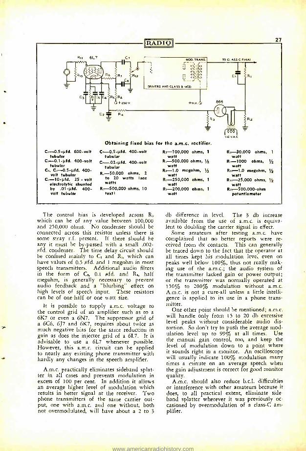
C3-0.5 -pfd. 600 -volt tubular
C3-0.1 -pfd. 400 -volt tubular
C3, C4-0.5 -0d, 400 - volt tubular
Ca-10 -pfd. 25 - volt electrolytic shunted by .01 -pfd. 400 - volt tubular
Obtaining fixed bias for the a.m.c. rectifier.
Ca-0.5 -pfd. 400 -volt tubular
C7-.02 -pfd. 400 -volt tubular
R,- 50,000 ohms, 2 to 20 watts (see watts
R3- 500,000 ohms, 10 text)
Cfb 6-1 110 V.A.0
2
Ra- 100,000 ohms, 1 R5- 30,000 ohms, 1
watt watt R,- 500,000 ohms, 1/2 R: -1000 ohms, '1/2
watt watt R5 -1.0 megohm, I/2 R,a -1.0 megohm, /2
watt watt RI, 250,000 ohms, 1 R11- 25,000 ohms, 1/2
watt watt R7- 200,000 ohms, 1 Ras- 500,000 -ohm
watt potentiometer
The control bias is developed across R, which can be of any value between 100,000 and 250,000 ohms. No condenser should be connected across this resistor unless there is some stray r.f. present. If there should be any it must be by- passed with a small .002 - pfd. condenser. The time delay circuit should be confined mainly to C, and R5, which can have values of 0.5 pfd. and 1 megohm in most speech transmitters. Additional audio filters in the form of C2, 0.1 pfd. and R4, half megohm, is generally necessary to prevent audio feedback and a "blurbing" effect on high levels of speech input. These resistors can be of one -half or one watt size.
It is possible to supply a.m.c. voltage to the control grid of an amplifier such as to a 6K7 or even a 6N7. The suppressor grid of a 6C6, 6J7 and 6K7, requires about twice as much negative bias for the same reduction in gain as does the injector grid of a 6L7. It is advisable to use a 6L7 whenever possible. However, this a.m.c. circuit can be applied to nearly any existing phone transmitter with hardly any changes in the speech amplifier.
A.m.c. practically eliminates sideband splat- ter in all cases and prevents modulation in excess of 100 per cent. In addition it allows an average higher level of modulation which results in better signal at the receiver. Two phone transmitters of the same carrier out- put, one with a.m.c. and one without, both not overmodulated, will have about a 2 to 3
db difference in level. The 3 db increase available from the use of a.m.c. is equiva- lent to doubling the carrier signal in effect.
Some amateurs after testing a.m.c. have complained that no better reports were re- ceived from dx contacts. This can generally be traced down to the fact that the operator at all times kept his modulation level even on peaks well below 100 %, thus not really mak- ing use of the a.m.c.; the audio system of the transmitter lacked gain or power output; or the transmitter was normally operated at 150% to 200% modulation without a.m.c. A.m.c. is not a cure -all unless a little intelli- gence is applied to its use in a phone trans- mitter.
One other point should be mentioned; a.m.c. will handle only from 15 to 20 db excessive level peaks without considerable audio dis- tortion. So don't try to push the average mod- ulation level up to 99% at all times. Use the manual gain control, too, and keep the level of modulation down to a point where it sounds right in a monitor. An oscilloscope will usually indicate 100% modulation many times a minute on an average speech when the gain adjustment is correct for good monitor quality.
A.m.c. should also reduce b.c.l. difficulties or interference with other amateurs because it does, to all practical extent, eliminate side - band splatter wherever it was previously oc- casioned by overmodulation of a class -C am- plifier.
www.americanradiohistory.com
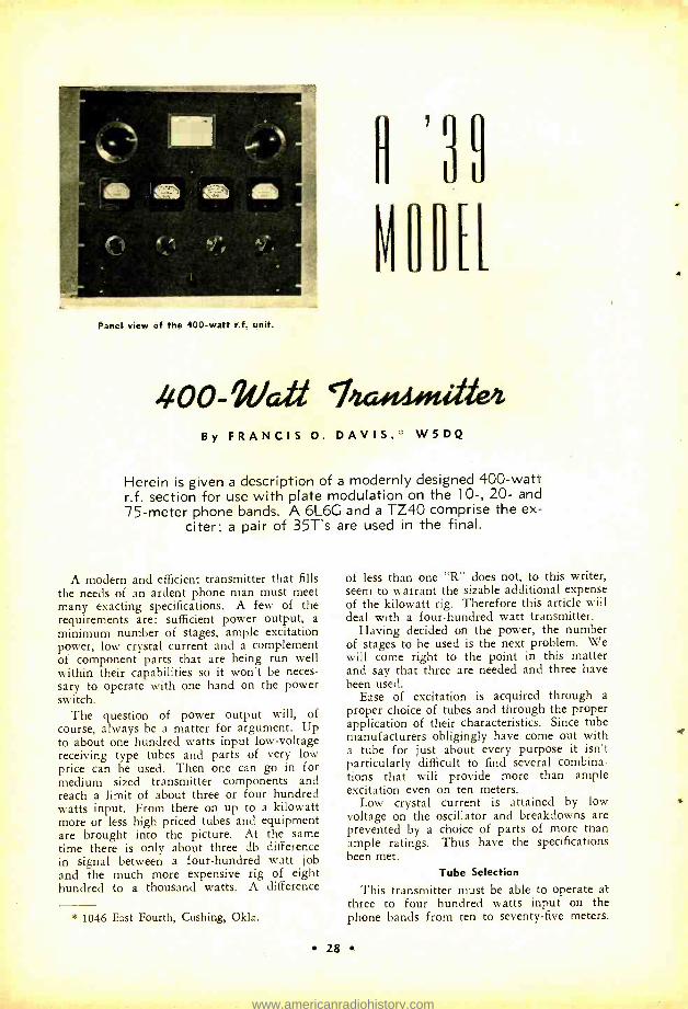
Panel view of the 400 -watt r.f. unit.
4 0 0- 2t/atí By FRANCIS O. DAVIS,: : W5DQ
Herein is given a description of a modernly designed 400 -watt r.f. section for use with plate modulation on the 10 -, 20- and 75 -meter phone bands. A 6L6G and a TZ40 comprise the ex-
citer; a pair of 35T's are used in the final.
A modern and efficient transmitter that fills the needs of an ardent phone man must meet many exacting specifications. A few of the requirements are: sufficient power output, a minimum number of stages, ample excitation power, low crystal current and a complement of component parts that are being run well within their capabilities so it won't be neces- sary to operate with one hand on the power switch.
The question of power output will, of course, always be a matter for argument. Up to about one hundred watts input low- voltage receiving type tubes and parts of very low price can be used. Then one can go in for medium sized transmitter components and reach a limit of about three or four hundred watts input. From there on up to a kilowatt more or less high priced tubes and equipment are brought into the picture. At the same time there is only about three db difference in signal between a four- hundred watt job and the much more expensive rig of eight hundred to a thousand watts. A difference
* 1046 East Fourth, Cushing, Okla.
of less than one "R" does not, to this writer, seem to warrant the sizable additional expense of the kilowatt rig. Therefore this article will deal with a four -hundred watt transmitter.
Having decided on the power, the number of stages to be used is the next problem. We will come right to the point in this matter and say that three are needed and three have been used.
Ease of excitation is acquired through a proper choice of tubes and through the proper application of their characteristics. Since tube manufacturers obligingly have come out with a tube for just about every purpose it isn't particularly difficult to find several combina- tions that will provide more than ample excitation even on ten meters.
Low crystal current is attained by low voltage on the oscillator and breakdowns are prevented by a choice of parts of more than ample ratings. Thus have the specifications been met.
Tube Selection
This transmitter must be able to operate at three to four hundred watts input on the phone bands from ten to seventy -five meters.
28
www.americanradiohistory.com
s
TZ40
IjA D I 0
La
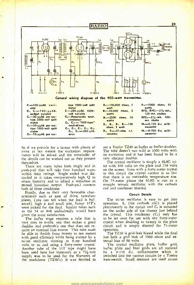
29
35T
Ce
H Gs
Y
RFC2
+1000V -90V zSV.A.c. 3.2Vn.C. +1600V.
General wiring diagram of the 400 -watt transmitter.
C1- 220 -µpfd. vari- able
C2, C3- 100 -ppfd. midget variable
C4 -30 -µpfd. per sec- tion 2000 -volt split stator
C,. 50 -ppfd. per sec- tion 1000 -volt split stator
C8- 70 -ppfd. per sec-
lion 7000 -volt split stator
C7 -250 -1111fd. 1000 - volt variable
C,- Homemade neut. condenser
Co, C,o - "800- type" neutralizers
C11, C,2, C13, C14, C15,
C14, C17- .002 -pfd. mica
R,- 100,000 ohms, 1
watt R2- 10,000 ohms, 2
watts R3 -2500 ohms, 10
watts R4, Rs, Rs, R, -100
ohms, 1 watt R,, Ro--25 -ohm c.t.
resistors
Rio- -5000 ohms, 10 watts
RFC,, RFC2- 21 /2 -mh., 125 -ma. chokes
RFC,- 21/2-mh. 500 - ma. choke
M,-0 -150 d.c. milli - ammeter
M2-0 -500 d.c. milli - ammeter
So if we provide for a layout with plenty of drive at ten meters the excitation require- ments will be solved and the remainder of the details can be worked out as they present themselves.
There are many tubes both singly and in push -pull that will take four hundred watts within their ratings. Single ended was dis- carded as it takes comparatively high Q to attain linearity and to afford a reduction in second harmonic output. Push -pull corrects both of these conditions.
Finally, due to their very favorable char- acteristics such as ease of drive, tantalum plates, (you can tell when the load is bal- anced) high and small size, Eimac 35T's were picked for the final. Similar tubes such as the 54 or 808 undoubtedly would have given the same satisfaction.
The buffer stage requires a tube that is very easy to excite, one that makes a good doubler and preferably one that does not re- quire an external bias source. This tube must be able to double from twenty to ten meters with good efficiency while being excited by a tri -tet oscillator running at three hundred volts or so and using a forty -meter crystal. Another tube of the 35T type might have been used here but inasmuch as a 71/2 -volt supply was to be used for the filaments of the modulator (TZ40's) it was decided to
use a Taylor TZ40 as buffer or buffer- doubler. The tube doesn't run wild at 1000 volts with no excitation and it has been found to be a very efficient doubler.
The crystal oscillator is simply a 6L6G tri- tet with 300 volts on the plate and 250 volts on the screen. Even with a forty -meter crystal in this circuit the crystal current is so low that there is no noticeable temperature rise. On 75 -meter phone the 6L6G is run as a straight tetrode oscillator with the cathode coil and condenser shorted.
Circuit Details
The tri -tet oscillator is easy to get into operation. L1 (the cathode coil) is placed permanently in the circuit and C1 is mounted on the under side of the chassis just behind the crystal. This condenser (C1) only has to be set once for use with any forty -meter crystal when doubling to twenty in the plate circuit and is simply shorted for 75 -meter operation.
The TZ40 is grid -leak biased while the final has both a grid leak of 5000 ohms and ex- ternal bias of 90 volts.
The crystal oscillator plate, buffer grid, buffer plate and final grids are all metered by a 0 -150 d.c. milliammeter which is switched into the various circuits by a Yaxley ham -switch. Small resistors are used across
www.americanradiohistory.com
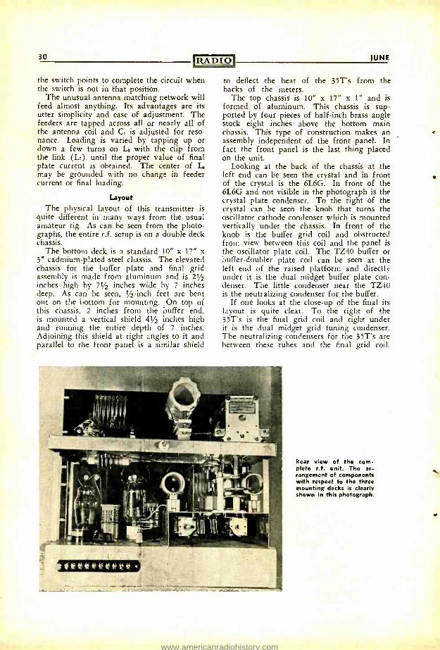
30
the switch points to complete the circuit when the switch is not in that position.
The unusual antenna matching network will feed almost anything. Its advantages are its utter simplicity and ease of adjustment. The feeders are tapped across all or nearly all of the antenna coil and G is adjusted for reso- nance. Loading is varied by tapping up or down a few turns on L. with the clip from the link (L7) until the proper value of final plate current is obtained. The center of L. may be grounded with no change in feeder current or final loading.
Layout The physical layout of this transmitter is
quite different in many ways from the usual amateur rig. As can be seen from the photo- graphs, the entire r.f. setup is on a double deck chassis.
The bottom deck is a standard 10" x 17" x 3" cadmium -plated steel chassis. The elevated chassis for the buffer plate and final grid assembly is made from aluminum and is 21/2 inches high by 71/2 inches wide by 7 inches deep. As can be seen, 1/2 -inch feet are bent out on the bottom for mounting. On top of this chassis, 2 inches from the buffer end, is mounted a vertical shield 41/2 inches high and running the entire depth of 7 inches. Adjoining this shield at right angles to it and parallel to the front panel is a similar shield
JUNE
to deflect the heat of the 35T's from the backs of the meters.
The top chassis is 10" x 17" x 1" and is formed of aluminum. This chassis is sup- ported by four pieces of half -inch brass angle stock eight inches above the bottom main chassis. This type of construction makes an assembly independent of the front panel. In fact the front panel is the last thing placed on the unit.
Looking at the back of the chassis at the left end can be seen the crystal and in front of the crystal is the 6L6G. In front of the 6L6G and not visible in the photograph is the crystal plate condenser. To the right of the crystal can be seen the knob that turns the oscillator cathode condenser which is mounted vertically under the chassis. In front of the knob is the buffer grid coil and obstructed from view between this coil and the panel is the oscillator plate coil. The TZ40 buffer or buffer -doubler plate coil can be seen at the left end of the raised platform and directly under it is the dual midget buffer plate con- denser. The little condenser near the TZ40 is the neutralizing condenser for the buffer.
If one looks at the close -up of the final its layout is quite clear. To the right of the 35T's is the final grid coil and right under it is the dual midget grid tuning condenser. The neutralizing condensers for the 35T's are between these tubes and the final grid coil.
Rear view of the com- plete r.f. unit. The ar- rangement of components with respect to the three mounting decks is clearly shown in this photograph.
a
www.americanradiohistory.com
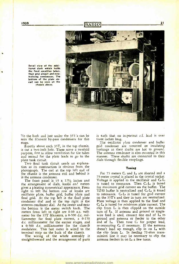
1939
Detail view of the addi- tional deck which holds the final amplifier tubes, their grid circuit and neu- tralizing condensers. The bottom of the plate cir- cuit can be seen on the
chassis above.
uRADIO 31
To the back and just under the 35T's can be seen the filament by -pass condensers for this stage.
Exactly above each 35T, in the top chassis, is cut a two -inch hole. These serve a twofold purpose, first to allow ventilation for the tubes and second for the plate leads to go to the plate tank circuit.
Two final tank circuit needs no explana- tion as its construction is obvious from the photograph. The coil at the top left end of the chassis is the antenna coil and behind it is the antenna condenser.
The front panel is 19 x 171/2 inches and the arrangement of dials, knobs and meters gives a pleasing symmetrical appearance. From right to left the bottom row of knobs are oscillator plate, buffer grid, buffer plate and final grid. At the top left is the final plate condenser dial and at the top right is the antenna condenser dial. At the center and near the bottom is the meter switch knob. The meters from left to right are 0 -10 a.c. volt- meter for the 35T filaments, a 0 -500 d.c. mil- liammeter for final plate current, a 0 -150 d.c. milliammeter for the exciter stages, and a 0 -500 d.c. milliammeter for the class -B modulator. This last meter is wired to the terminal strip on the back of the chassis.
The wiring of the whole assembly is straightforward and the arrangement of parts
is such that no important r.f. lead is over three inches long.
The oscillator plate condenser and buffer grid condenser are mounted on insulating bushings as their shafts are hot to ground. The antenna condenser is also mounted in this manner. These shafts are connected to theft dials through flexible couplings.
Tuning
For 75 meters C, and L, are shorted and a
75 -meter crystal is placed in the crystal socket. Voltage is applied to the oscillator and G -L, is tuned to resonance. Then C, -L, is tuned for maximum grid current on the buffer. The TZ40 buffer is neutralized and C.-L, is tuned to resonance. G -L5 is tuned for grid current on the 35T's and they in turn are neutralized. Plate voltage is then applied to the final and C.-L. is tuned for minimum plate current. The clip from L, is then clipped on the outside turn of L. If antenna and ground or single - wire feed is used, connect one end of L. to ground and antenna or feeder to the other end of L.. Then tune C, for proper load, re- resonating G if necessary. If the antenna doesn't load up enough, clip in on L. with the clip from L. In feeding 72 -ohm trans- mission line it may be necessary to clip the antenna feeders in on L. a few turns.
www.americanradiohistory.com
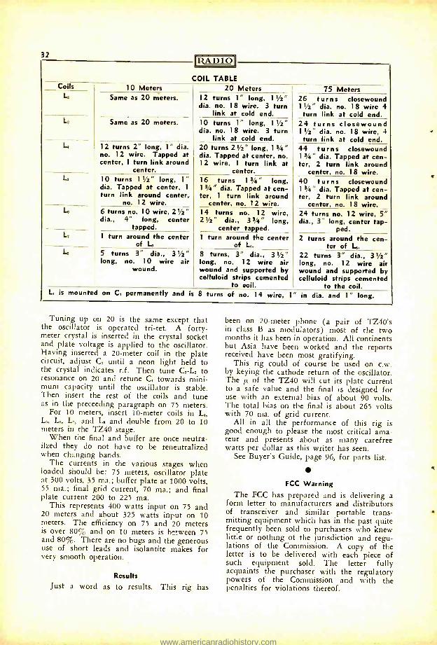
4
32 ADIO
COIL TABLE Coils
L_
L
L
10 Meters 20 Meters 75 Meters Same as 20 meters. 12 turns 1" long, 11/2"
dia. no. 18 wire. 3 turn link at cold end.
26 turns closewound 1 Y2" dia. no. 18 wire 4 turn link at cold end.
Same as 20 meters. 10 turns 1" long, 11/2" dia. no. 18 wire. 3 turn
link at cold end.
24 turns closewound 11/2" dia. no. 18 wire, 4 turn link at cold end.
12 turns 2" long, 1" dia. no. 12 wire. Tapped at center, 1 turn link around
center.
20 turns 21/2" long, 13/4" dia. Tapped at center, no. 12 wire, 1 turn link at
center.
44 turns closewound 13/4" dia. Tapped at cen- ter, 2 turn link around
center, no. 18 wire. L 10 turns 11/2" long, 1"
dia. Tapped at center, 1
turn link around center, no. 12 wire.
16 turns 13/4" long, 13/4" dia. Tapped at cen- ter, 1 turn link around
center, no. 12 wire.
40 turns closewound 13/4" dia. Tapped at cen- ter, 2 turn link around
center, no. 18 wire. Le
L7
6 turns no. 10 wire, 21/2" dia., 4" long, center
tapped.
14 turns no. 12 wire, 21/2" dia., 33/4" long,
center tapped.
24 turns no. 12 wire, 5" dia., 3 long, center tap-
ped. 1 turn around the center
of L 1 turn around the center
of L. 2 turns around the cen-
ter of L 5 turns 3" dia., 31/2"
long, no. 10 wire air wound.
8 turns, 3" dia., 31/2" long, no. 12 wire air wound and supported by celluloid strips cemented
to eoil.
22 turns 3" dia., 31/2" long, no. 12 wire air wound and supported by celluloid strips cemented
to the coil. L, is mounted on C, permanently and is 8 turns of no. 14 wire, 1" in dia. and 1" long.
Tuning up on 20 is the same except that the oscillator is operated tri -tet. A forty - meter crystal is inserted in the crystal socket and plate voltage is applied to the oscillator. Having inserted a 20 -meter coil in the plate circuit, adjust C, until a neon light held to the crystal indicates r.f. Then tune C : -L: to resonance on 20 and retune C, towards mini- mum capacity until the oscillator is stable. Then insert the rest of the coils and tune as in the preceeding paragraph on 75 meters.
For 10 meters, insert 10 -meter coils in Ls, L L,, L,, and L. and double from 20 to 10 meters in the TZ40 stage.
When the final and buffer are once neutra- ilzed they do not have to be reneutralized when changing bands.
The currents in the various stages when loaded should be: 75 meters, oscillator plate at 300 volts, 35 ma.; buffer plate at 1000 volts, 55 ma.; final grid current, 70 ma.; and final plate current 200 to 225 ma.
This represents 400 watts input on 75 and 20 meters and about 325 watts input on 10 meters. The efficiency on 75 and 20 meters is over 80% and on 10 meters is between 75 and 80%. There are no bugs and the generous use of short leads and isolantite makes for very smooth operation.
Results
Just a word as to results. This rig has
been on 20 -meter phone (a pair of TZ40's in class B as modulators) most of the two months it has been in operation. All continents but Asia have been worked and the reports received have been most gratifying.
This rig could of course be used on c.w. by keying the cathode return of the oscillator. The of the TZ40 will cut its plate current to a safe value and the final is designed for use with an external bias of about 90 volts. The total bias on the final is about 265 volts with 70 ma. of grid current.
All in all the performance of this rig is good enough to please the most critical ama- teur and presents about as many carefree watts per dollar as this writer has seen.
See Buyer's Guide, page 96, for parts list.
FCC Warning The FCC has prepared and is delivering a
form letter to manufacturers and distributors of transceiver and similar portable trans- mitting equipment which has in the past quite frequently been sold to purchasers who knew little or nothing of the jurisdiction and regu- lations of the Commission. A copy of the letter is to be delivered with each piece of such equipment sold. The letter fully acquaints the purchaser with the regulatory powers of the Commission and with the penalties for violations thereof.
www.americanradiohistory.com
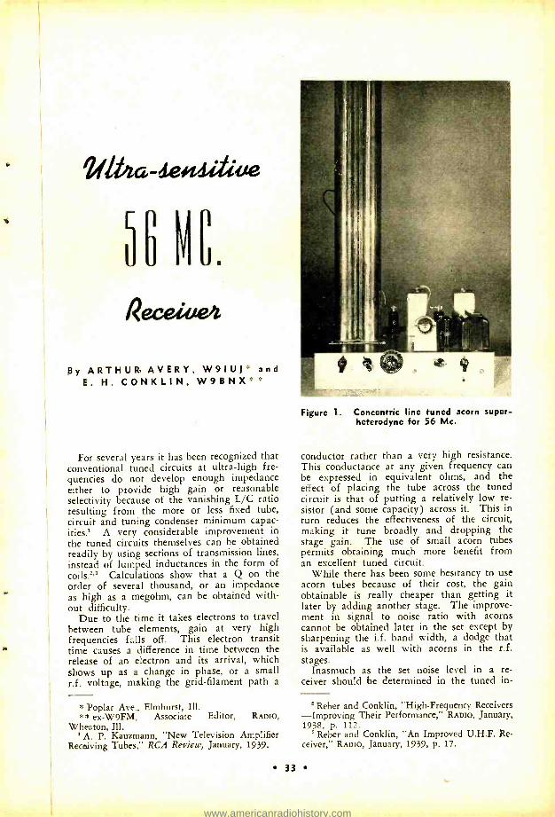
Vibia-deiiidttae
56 NC.
Receitie4
By ARTHUR AVERY, W9IUl and E. H. CONKLIN, W9BNX
For several years it has been recognized that conventional tuned circuits at ultra -high fre- quencies do not develop enough impedance either to provide high gain or reasonable selectivity because of the vanishing L/C ratio resulting from the more or less fixed tube, circuit and tuning condenser minimum capac- ities.' A very considerable improvement in the tuned circuits themselves can be obtained readily by using sections of transmission lines, instead of lumped inductances in the form of coils.'' Calculations show that a Q on the order of several thousand, or an impedance as high as a megohm, can be obtained with- out difficulty.
Due to the time it takes electrons to travel between tube elements, gain at very high frequencies falls off. This electron transit time causes a difference in time between the release of an electron and its arrival, which shows up as a change in phase, or a small r.f. voltage, making the grid- filament path a
* Poplar Ave., Elmhurst, Ill. * * ex -W9FM, Associate Editor, RADIO,
Wheaton, Ill. ' A. P. Kauzmann, "New Television Amplifier
Recoiving Tubes," RCA Review, January, 1939.
Figure 1. Concentric line tuned acorn super- heterodyne for 56 Mc.
conductor rather than a very high resistance. This conductance at any given frequency can be expressed in equivalent ohms, and the effect of placing the tube across the tuned circuit is that of putting a relatively low re- sistor (and some capacity) across it. This in turn reduces the effectiveness of the circuit, making it tune broadly and dropping the stage gain. The use of small acorn tubes permits obtaining much more benefit from an excellent tuned circuit.
While there has been some hesitancy to use acorn tubes because of their cost, the gain obtainable is really cheaper than getting it later by adding another stage. The improve- ment in signal to noise ratio with acorns cannot be obtained later in the set except by sharpening the i.f. band width, a dodge that is available as well with acorns in the r.f. stages.
Inasmuch as the set noise level in a re- ceiver should be determined in the tuned in-
Reber and Conklin, "High- Frequency Receivers -Improving Their Performance," RAnro, January, 1938, p. 112.
' Reber and Conklin, "An Improved U.H.F. Re- ceiver," RADIO, January, 1939, p. 17.
33
www.americanradiohistory.com
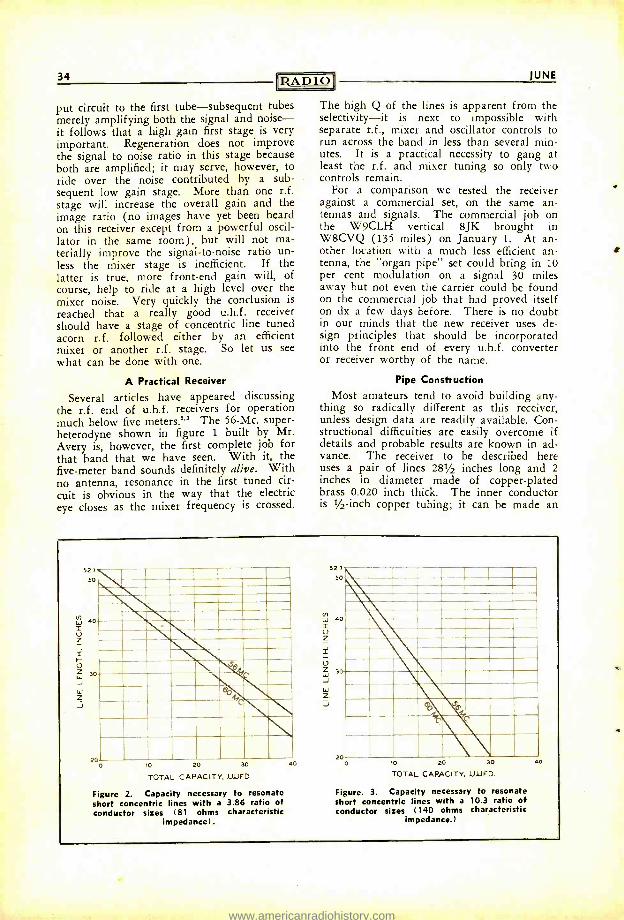
34 RADIO'
put circuit to the first tube -subsequent tubes merely amplifying both the signal and noise - it follows that a high gain first stage is very important. Regeneration does not improve the signal to noise ratio in this stage because both are amplified; it may serve, however, to ride over the noise contributed by a sub- sequent low gain stage. More than one r.f. stage will increase the overall gain and the image ratio (no images have yet been heard on this receiver except from a powerful oscil- lator in the same room), but will not ma- terially improve the signal -to -noise ratio un- less the mixer stage is inefficient. If the latter is true, more front -end gain will, of course, help to ride at a high level over the mixer noise. Very quickly the conclusion is
reached that a really good u.h.f. receiver should have a stage of concentric line tuned acorn r.f. followed either by an efficient mixer or another ri. stage. So let us see what can be done with one.
A Practical Receiver
Several articles have appeared discussing the ri. end of u.h.f. receivers for operation much below five meters.2 3 The 56 -Mc. super- heterodyne shown in figure 1 built by Mr. Avery is, however, the first complete job for that band that we have seen. With it, the five -meter band sounds definitely alive. With no antenna, resonance in the first tuned cir-
cuit is obvious in the way that the electric eye closes as the mixer frequency is crossed.
JUNE
The high Q of the lines is apparent from the selectivity -it is next to impossible with separate r.f., mixer and oscillator controls to run across the band in less than several min- utes. It is a practical necessity to gang at least the r.f. and mixer tuning so only two controls remain.
For a comparison we tested the receiver against a commercial set, on the same an- tennas and signals. The commercial job on the W9CLH vertical 8JK brought in W8CVQ (135 miles) on January 1. At an- other location with a much less efficient an- tenna, the "organ pipe" set could bring in 10 per cent modulation on a signal 30 miles away but not even the carrier could be found on the commercial job that had proved itself on dx a few days before. There is no doubt in our minds that the new receiver uses de- sign principles that should be incorporated into the front end of every u.h.f. converter or receiver worthy of the name.
Pipe Construction
Most amateurs tend to avoid building any- thing so radically different as this receiver, unless design data are readily available. Con- structional difficulties are easily overcome if details and probable results are known in ad- vance. The receiver to be described here uses a pair of lines 281/2 inches long and 2 inches in diameter made of copper -plated brass 0.020 inch thick. The inner conductor is 1/2 -inch copper tubing; it can be made an
52, 50
o
o
20 10 20 30
TOTAL CAPACITY. LUFD
Figure 2. Capacity necessary to resonate short concentric lines with a 3.86 ratio of conductor sizes (81 ohms characteristic
impedance).
52 7
50
S U
Fu
Z
Z J
-
3
vk - -111M-- ---Rrn
W a o
W
Z J
20 o 10 20 30
TOTAL CAPACITY. LJJFD
Figure. 3. Capacity necessary to resonate short concentric lines with a 10.3 ratio of conductor sizes (140 ohms characteristic
impedance.)
ac
s
www.americanradiohistory.com
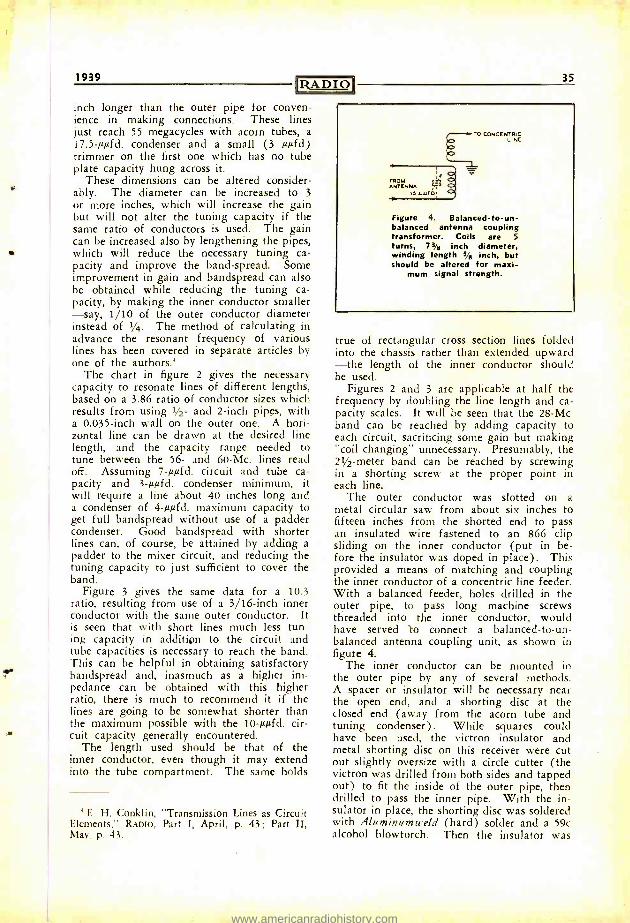
1939 RADIO inch longer than the outer pipe for conven- ience in making connections. These lines just reach 55 megacycles with acorn tubes, a 17.5 -µµfd. condenser and a small (3 µµfd) trimmer on the first one which has no tube plate capacity hung across it.
These dimensions can be altered consider- ably. The diameter can be increased to 3
or more inches, which will increase the gain but will not alter the tuning capacity if the same ratio of conductors is used. The gain can be increased also by lengthening the pipes, which will reduce the necessary tuning ca- pacity and improve the band -spread. Some improvement in gain and bandspread can also be obtained while reducing the tuning ca- pacity, by making the inner conductor smaller -say, 1/10 of the outer conductor diameter instead of 1/4. The method of calculating in advance the resonant frequency of various lines has been covered in separate articles by one of the authors'
The chart in figure 2 gives the necessary capacity to resonate lines of different lengths, based on a 3.86 ratio of conductor sizes which results from using 1 /2- and 2 -inch pipes, with a 0.035 -inch wall on the outer one. A hori- zontal line can be drawn at the desired line length, and the capacity range needed to tune between the 56- and 60 -Mc. lines read off. Assuming 7 -µµfd. circuit and tube ca- pacity and 3 -µµfd. condenser minimum, it will require a line about 40 inches long and a condenser of 4 -µµfd. maximum capacity to get full bandspread without use of a padder condenser. Good bandspread with shorter lines can, of course, be attained by adding a padder to the mixer circuit, and reducing the tuning capacity to just sufficient to cover the band.
Figure 3 gives the same data for a 10.3 ratio, resulting from use of a 3/16 -inch inner conductor with the same outer conductor. It is seen that with short lines much less tun- ing capacity in addition to the circuit and tube capacities is necessary to reach the band. This can be helpful in obtaining satisfactory bandspread and, inasmuch as a higher im- pedance can be obtained with this higher ratio, there is much to recommend it if the lines are going to be somewhat shorter than the maximum possible with the 10 -µµEd. cir- cuit capacity generally encountered.
The length used should be that of the inner conductor, even though it may extend into the tube compartment. The same holds
' F.. H. Conklin, "Transmission Lines as Circuit Elements," RADIO, Part I, April, p. 43; Part II, May, p. 43.
35
(ROM ANTENNA -
1! L1/(0
TO CONCENTRIC LINE
Figure 4. Balanced- to -un- balanced antenna coupling transformer. Coils are 5
turns, 73,8 inch diameter, winding length 5'8 inch, but should be altered for maxi-
mum signal strength.
true of rectangular cross section lines folded into the chassis rather than extended upward -the length of the inner conductor should be used.
Figures 2 and 3 are applicable at half the frequency by doubling the line length and ca- pacity scales. It will be seen that the 28 -Mc. band can be reached by adding capacity to each circuit, sacrificing some gain but making "coil changing" unnecessary. Presumably, the 21/2-meter band can be reached by screwing in a shorting screw at the proper point in each line.
The outer conductor was slotted on a metal circular saw from about six inches to fifteen inches from the shorted end to pass an insulated wire fastened to an 866 clip sliding on the inner conductor (put in be- fore the insulator was doped in place). This provided a means of matching and coupling the inner conductor of a concentric line feeder. With a balanced feeder, holes drilled in the outer pipe, to pass long machine screws threaded into the inner conductor, would have served 'to connect a balanced- to -un- balanced antenna coupling unit, as shown in figure 4.
The inner conductor can be mounted in the outer pipe by any of several methods. A spacer or insulator will be necessary near the open end, and a shorting disc at the closed end (away from the acorn tube and tuning condenser). While squares could have been used, the victron insulator and metal shorting disc on this receiver were cut out slightly oversize with a circle cutter (the victron was drilled from both sides and tapped out) to fit the inside of the outer pipe, then drilled to pass the inner pipe. With the in- sulator in place, the shorting disc was soldered with Aluminumweld (hard) solder and a 59c alcohol blowtorch. Then the insulator was
www.americanradiohistory.com
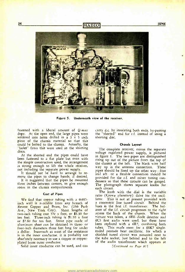
36 RADIO IUNE
Figure 5. Underneath view of the receiver.
fastened with a liberal amount of Q -max dope. At the open end, the large pipes were soldered into holes drilled in a 3 x 5 inch piece of the chassis material so that this could be bolted to the chassis. Actually, the "holes". from this were used as the shorting discs.
At the shorted end the pipes could have been fastened to a flat plate but even with the simple construction used, the arrangement is strong enough to lift the whole receiver, not including the separate power supply.
It should not be hard to arrange to re- move the pipes to change bands, if desired.
It is suggested that the pipes be mounted three inches between centers, to give enough room in the chassis compartments.
Cost of Pipes
We find that copper tubing with a 0.035 - inch wall is available from any branch of Revere Copper and Brass, Inc. (230 Park Ave., New York City). Short lengths of two -inch tubing cost 37c a foot, or $3.30 for ten feet. Three -inch tubing is $1.10 a foot or $7.60 for ten feet. Stove pipe made of aluminum sheet can be obtained in three- or four -inch diameters three feet long for under a dollar. Inasmuch as most of the resistance is in the inner conductor, it is probably not absolutely necessary to use a copper or copper - plated brass outer conductor.
Solid inner conductor can be used, and can
carry d.c. by insulating both ends, by- passing the "shorted" end for r.f. instead of using a shorting disc.
Chassis Layout
The complete receiver, minus the separate voltage regulated power supply, is pictured in figure 1. The two pipes are distinguished rising up out of the picture from the top of the chassis at the left. The black wire half way up is the antenna connection. These pipes should be lined up the other way -fore and aft -or a flexible connection should be provided for the r.f. and mixer tuning con- densers so that these circuits can be ganged. The photograph shows separate knobs for each circuit.
The knob with the dial is the variable ratio (Crowe planetary) drive for the oscil- lator. This is not at present provided with a concentric line tuned circuit. Behind the lines is the first i.f. transformer. The bal- ance of the i.f. circuit progresses to the right across the back of the chassis. When the picture was taken, a 6H6 diode detector and 6C5 first audio were used, but these have been replaced with a 6R7, combining both tubes. This made room for a 6SK7 single - ended pentode beat oscillator, for which a shielded tuned circuit was mounted next to the tube socket, just behind and to the left of the audio transformer which appears at
[Continued on Page RI]
www.americanradiohistory.com
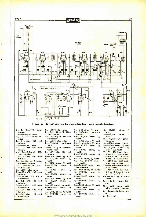
1939
ANT
1
L.
rRADIO 37
TO 6E5 F USED
O L2
C
T`9 _QQ_Q.00,
6. 3 V TO HEATERS
54 novAÇ.
Figure 6. Circuit diagram for concentric line tuned superheterodyne.
C,, C_, C, -17.5 ppfd. midget
C1- .0001 -pfd. mica C3, Ce, C. - .0005 -pfd.
mica C. -.01 - pfd. 400 - volt
tubular C, -.006 -pfd. mica C.. -.O1 - pfd. 400 - volt
tubular C,., C12-0.1-pfd. 400 -
volt tubular - pfd. 400 - volt
tubular Cu, Cr. C - 0.1 -pfd.
400 -volt tubular C,7, C,, -.01 -pfd. 400 -
volt tubular C. -.0001 -pfd. mica
- pfd. 400 - volt tubular
Cs, -10 -0d. 25-volt electrolytic
C13-0.1 - pfd. 400 - volt tubular
- pfd. 450 - volt electrolytic
C3. -.01 - pfd. 400 - volt tubular
Cam. -10 - pfd. 50 - volt electrolytic
C3, -.0001 -pfd. mica Co, 3 C33 -.01 - pfd. 400 -
volt tubular Cn, C.3, -8 -pfd. 450 -volt
electrolytic C:..- .0005 -pfd. mica C..- Twisted pushback
wire C,3 -3 -30 -ppfd, trimmer,
wide open - pfd. 400 - volt
tubular R, -1500 ohms, 1/2 watt R2- 100,000 ohms, 1/2
watt 8-2000 ohms, 1/2 watt R.- 100,000 ohms, 1
watt R3- 50,000 ohms,
watt R,,- 100,000 ohms,
watt R. -2000 ohms, 1/2 watt R.- 100,000 ohms, 1/2
watt R: -300 ohms, 1/2 watt R,;- 100,000 ohms, 1/2
watt R,,-2000 ohms, 1/2 watt R1- 100,000 ohms, 1/2
watt
1/2
1/2
R,3 -300 ohms, 1/2 watt R,. -500 -ohm potenti-
ometer R- 100,000 ohms, 1/2
watt R,0-2000 ohms, 1/2 watt Ro -1 megohm, 1/2 watt R,..- 500,000 ohms, 1/2
watt R- 50,000 ohms, 1/2 watt
Re0- 500,000 ohms, 1/2
watt R3, -800 ohms, 1/2 watt R23, R1,- 50,000 ohms,
1/2 watt R3,- 500,000 - ohm po-
tentiometer R3: -600 ohms, 10 watts R33- 100,000 ohms, 1/2
watt Re:- 250,000
watt R2..- 500,000 ohms, 1/2
watt R2: -5000 ohms, 1/2 watt
(see text) R :- 50,000 ohms, 1/2
watt R3,- 500,000 ohms, 1/2
watt
ohms, 1/2
R0- 10,000 ohms, 1
watt R1- 25,000 ohms, 1
watt R:o- 10,000 -ohm poten-
tiometer R.-5000 ohms, 1 watt RA -2000 ohms, 1/2 watt R:n- 10,000 ohms, 1/2
watt (see text) T., T3- 3500 -kc. inter -
stage i.f. transformer T:. -3500 - kc. plate -to-
diode i.f. transformer T.- 3500 -kc. beat- oscil-
lator transformer T:,- Pentode -to- voice -coi l
transformer 7.;-750 v. c.t., 125 ma.;
6.3 v., 3.6 a.; 5 v., 3
a.; 2.5 v., 3.5 a. CH - 30 - hy. 75 - ma.
choke S., Se, S:., S.- S.p.s.t. tog-
gle N -1 -watt neon bulb
with resistor removed L,- Concentric lines (see
text) 1,-See text
www.americanradiohistory.com
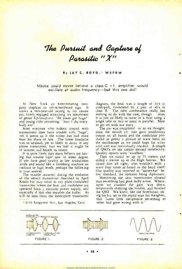
Tite &Wait and eari,r4e a pahadific X,,
By JAY C. BOYD,' W6PRM
Maybe you'd never believe a class -C r.f. amplifier would oscillate at audio frequency -but this one did!
In New York an exterminating com- pany displays an oft- remembered sign. It shows a two -year -old saying to his canine pal, busily engaged scratcning his assortment of genus Siphonaptera: "Be youse got bugs ?" and young Fido answering: "Sure I do, every- body are!"
Most everyone who tinkers around with transmitters does have trouble with "bugs ", but it seems as if the writer has had more than his share of late. The latest headache was so unusual, yet so likely to occur in any phone transmitter, that we feel it might be of interest and benefit to others.
It is quite likely that some fellows are hav- ing this trouble right now in lesser degree. If you have good quality at low modulation levels and sound like a threshing machine on medium or high levels, perhaps the following is your answer.
The trouble occurred during the evolution of the rebuilt transmitter described in April RADIO but may occur in any plate -modulated transmitter where the final and modulator are operated from a common power supply, and especially if this also supplies the buffer. As will be seen from the incomplete transmitter
*° 2119 Longwood Ave., Los Angeles, Calif.
diagram, the final was a couple of 10's in push -pull, modulated by a pair of 46's in class B. The tube combination really has nothing to do with the case, though. Also, it is just as likely to occur in a final using a single tube or two or more in parallel. Now to get on with our story:
The job was completed -or so we thought, since the rebuilt r.f. unit gave satisfactory output on all bands and the modulator pro- duced as pretty a picture of wave form on the oscilloscope as we could hope for when each unit was individually checked. A couple of QSO's on ten meters seemed satisfactory. Quality reports were "excellent."
Then we tuned 'er up to 75 meters and called a station up in the High Sierras. We raised him all right; who wouldn't with a wave four times as broad as the band itself! Our quality was reported as "somewhat" be- low standard, the operator being diplomatic.
Monitoring the next transmission showed that something had gone sadly amiss. Where- upon we cranked the gain 'way down, temporarily stopping the trouble, and finished the QSO. We knew, like the Scotchman tak- ing his b.c. set to the repair man for slaughter, that "some little inexpensive something or other had gone wrong with it."
MODULATION GOING UP r -PAR SITIC BEGINS
1811111110 UNMODULATED CARRIER CUT OFF PURE 5NE WAVE CARRIER COMPLETELY
FIGURE 1 FIGURE 2 FIGURE 3
38
www.americanradiohistory.com
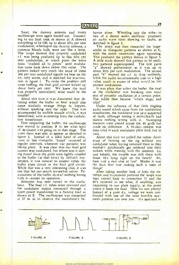
fIZA D I O
Next, the dummy antenna and trusty oscilloscope were again hauled out. Connect- ing to our final tank as shown at A showed everything to be OK up to about fifty per cent modulation, whereupon the dummy antenna, a common Mazda bulb, went out like a lamp. The 'scope showed that properly modulated r.f. was being produced up to this fifty per cent modulation, at which point the wave form "cracked all to pieces" until modula- tion came back down below this value. The pattern looked very much like some of these 200 per cent modulated signals we hear on the air, only worse, and is sketched for examina- tion in figure 1. To make the problem still more baffling, the final grid current kicked up about forty per cent. We knew the final was properly neutralized; what could be the trouble?
About this time it was discovered that de- tuning either the buffer or final would also cause similarly strange things to happen, without speaking into the mike. This was accompanied by audible sounds which, it was determined, were emanating from the modula- tion transformer.
First suspecting the buffer, the oscilloscope was moved to position B to see what kind of devilment was going on in that stage. The wave form was seen to appear as sketched in figure 2. Instead of a solid band of color, more or less triangular "burps" occurred at regular intervals, whenever our parasitic was taking place. It was clear that our final grid current was modulated, but where was it com- ing from? Since the grids were tightly coupled to the buffer (at that time) by .002 -µfd. con- densers, it was natural to suspect either the buffer plate circuit or the final grid circuit. While this was a very interesting clue, it was one that led our search somewhat astray. Ex- amination of the buffer showed nothing wrong with it- except its operation.
Attention was next turned to the modu- lator. The final r.f. tubes were removed and the modulator output connected through a spare power transformer to a dummy load as shown at E. The oscilloscope was connected at D so as to observe the modulator's be-
39
havior alone. Whistling into the mike -in lieu of a decent audio oscillator -produced an audio wave form showing no faults, as sketched in figure 3.
The 'scope was then connected for trape- zoidal or triangular patterns as shown at C, with the entire transmitter again operating. This produced the pattern shown in figure 4. A little study showed this pattern to be really two patterns superimposed. The first parts "a" showed performance as it was up to about fifty per cent modulation. The second part "b" showed the r.f. to drop suddenly, while the audio simultaneously rose to a high value, much in excess of what would he 100 percent modulation.
It was plain that either the buffer, the final or the modulator was breaking into some sort of parasitic oscillation at a certain point. The riddle then became "which stage, and why ?"
Under the influence of that little tingling audio sound which came from the modulation transformer, the modulator was next suspected of fault, although testing it individually had shown nothing wrong with it. Swamping resistors were placed across the 46 grids but made no difference. A 50 -ohm resistor was then tried in each modulator plate lead, but in vain.
About this time we pulled the rather dumb stunt of turning on the rig without any modulator tubes, having removed them so they wouldn't accidentally get soldered into their sockets while messing with the resistors. Lo, and behold, the trouble was still there with those 46's lying right on the bench! Ah, here was a real clue at last! Maybe it was the final that was making such a mess of things!
After taking another look at both the en- velope and trapezoidal patterns the 'scope was then moved back to connection D and the 46's removed to see what, if anything, was happening to our plate supply, at the point where it feeds the final. Here we saw plenty! Instead of a pure d.c. voltage we were con- fronted with one of the most horrible saw - tooth patterns you ever saw. It's sketched in
IIIIIIIIIIIIIIIIII
FIGURE 4 FIGURE 5 FIGURE 6
www.americanradiohistory.com
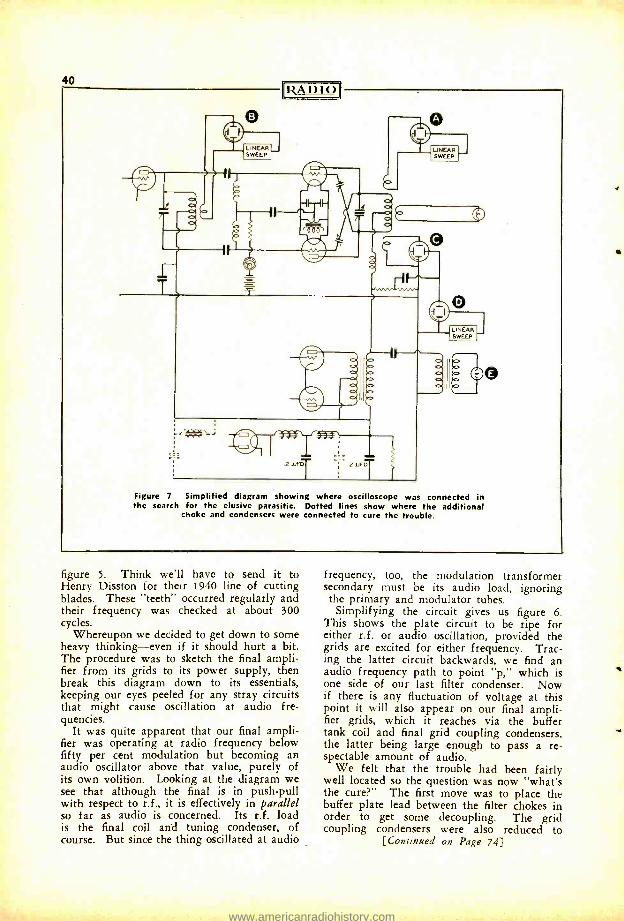
40 IRA DIO
LINEAR SWEEP
2 .UFDT
1
211F
Figure 7. Simplified diagram showing where oscilloscope was connected in the search for the elusive parasitic. Dotted lines show where the additional
choke and condensers were connected to cure the trouble.
figure 5. Think we'll have to send it to Henry Disston for their 1940 line of cutting blades. These "teeth" occurred regularly and their frequency was checked at about 300 cycles.
Whereupon we decided to get down to some heavy thinking -even if it should hurt a bit. The procedure was to sketch the final ampli- fier from its grids to its power supply, then break this diagram down to its essentials, keeping our eyes peeled for any stray circuits that might cause oscillation at audio fre- quencies.
It was quite apparent that our final ampli- fier was operating at radio frequency below fifty per cent modulation but becoming an audio oscillator above that value, purely of its own volition. Looking at the diagram we see that although the final is in push -pull with respect to r.f., it is effectively in parallel so far as audio is concerned. Its r.f. load is the final coil and tuning condenser, of course. But since the thing oscillated at audio
frequency, too, the modulation transformer secondary must be its audio load, ignoring the primary and modulator tubes.
Simplifying the circuit gives us figure 6. This shows the plate circuit to be ripe for either r.f. or audio oscillation, provided the grids are excited for either frequency. Trac- ing the latter circuit backwards, we find an audio frequency path to point "p," which is one side of our last filter condenser. Now if there is any fluctuation of voltage at this point it will also appear on our final ampli- fier grids, which it reaches via the buffer tank coil and final grid coupling condensers, the latter being large enough to pass a re- spectable amount of audio.
We felt that the trouble had been fairly well located so the question was now "what's the cure ?" The first move was to place the buffer plate lead between the filter chokes in order to get some decoupling. The grid coupling condensers were also reduced to
[Continued on Page 74)
www.americanradiohistory.com
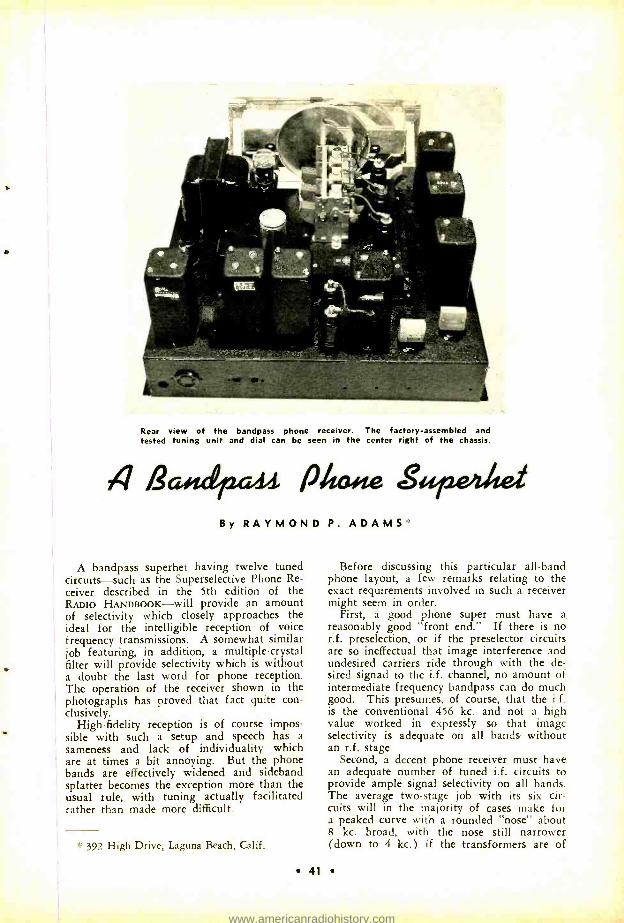
Rear view of the bandpass phone receiver. The factory- assembled and tested tuning unit and dial can be seen in the center right of the chassis.
4 ßad42a44 sir By RAYMOND P. ADAMS
A bandpass superhet having twelve tuned circuits -such as the Superselective Phone Re- ceiver described in the 5th edition of the RADIO HANDBOOK -will provide an amount of selectivity which closely approaches the ideal for the intelligible reception of voice frequency transmissions. A somewhat similar job featuring, in addition, a multiple -crystal filter will provide selectivity which is without a doubt the last word for phone reception. The operation of the receiver shown in the photographs has proved that fact quite con- clusively.
High -fidelity reception is of course impos- sible with such a setup and speech has a sameness and lack of individuality which are at times a bit annoying. But the phone bands are effectively widened and sideband splatter becomes the exception more than the usual rule, with tuning actually facilitated rather than made more difficult.
* 392 High Drive, Laguna Beach, Calif.
Before discussing this particular all -band phone layout, a few remarks relating to the exact requirements involved in such a receiver might seem in order.
First, a good phone super must have a reasonably good "front end." If there is no r.f. preselection, or if the preselector circuits are so ineffectual that image interference and undesired carriers ride through with the de- sired signad to the i.f. channel, no amount of intermediate frequency bandpass can do much good. This presumes, of course, that the i.f. is the conventional 456 kc. and not a high value worked in expressly so that image selectivity is adequate on all bands without an r.f. stage.
Second, a decent phone receiver must have an adequate number of tuned i.f. circuits to provide ample signal selectivity on all bands. The average two -stage job with its six cir- cuits will in the majority of cases make for a peaked curve with a rounded "nose" about 8 kc. broad, with the nose still narrower (down to 4 kc.) if the transformers are of
41
www.americanradiohistory.com
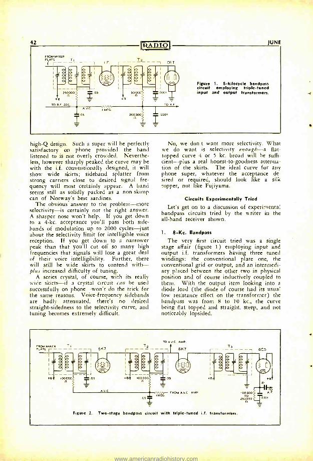
42
FROM MIXER PLATE T1
RADIO
T2
JUNE
DET
Figure 1. 8- kilocycle bandpass circuit employing triple -tuned input and output transformers.
high -Q design. Such a super will be perfectly satisfactory on phone provided the band listened to is not overly crowded. Neverthe- less, however sharply peaked the curve may be with the i.f. conventionally designed, it will show wide skirts; sideband splatter from strong carriers close to desired signal fre- quency will most certainly appear. A band seems still as solidly packed as a non -skimp can of Norway's best sardines.
The obvious answer to the problem -more selectivity -is certainly not the right answer. A sharper nose won't help. If you get down to a 4 -kc. acceptance you'll pass both side - hands of modulation up to 2000 cycles -just about the selectivity limit for intelligible voice reception. If you get down to a narrower peak than that you'll cut off so many high frequencies that signals will lose a great deal of their voice intelligibility. Further, there will still be wide skirts to contend with - plus increased difficulty of tuning.
A series crystal, of course, with its really wide skirts -if a crystal circuit can be used successfully on phone -won't do the trick for the same reasons. Voice- frequency sidebands are badly attenuated, there's no desired straight- sidedness to the selectivity curve, and tuning becomes extremely difficult.
No, we don't want more selectivity. What we do want is selectivity enough -a flat - topped curve 4 or 5 kc. broad will be suffi- cient -plus a real honest -to- goodness attenua- tion of the skirts. The ideal curve for any phone super, whatever the acceptance de- sired or required, should look like a silk topper, not like Fujiyama.
Circuits Experimentally Tried
Let's get on to a discussion of experimental bandpass circuits tried by the writer in the all -band receiver shown.
1. 8 -Kc. Bandpass
The very first circuit tried was a single stage affair (figure 1) employing input and output i.f. transformers having three tuned windings: the conventional plate one, the conventional grid or output, and an intermedi- ary placed between the other two in physical position and of course inductively coupled to them. With the output item looking into a
diode load (the diode of course had its usual low resistance effect on the transformer) the bandpass was from 8 to 10 kc., the curve being flat topped and straight, steep, and not noticeably lopsided.
FROM MIXER T1 PLATE r
A.V.
T2
+B 100000 n
TO A.V.C. AMP.
6K7
Figure 2.
052
05 2 1 MEC.
1
FROM A.V.0 AMP.
Ta 6C5
I i
i I
i I
L J +e
69
Two -stage bandpass circuit with triple -tuned i.f. transformers.
100000 TO
250000
ol
+6
A.F
0001
www.americanradiohistory.com
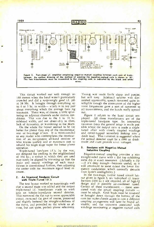
1939
FROM MIXER PLATE
-T T2
- 6K7 T3
1I T4
43
6K7 T5
1 I-
TO A.V.C. AMP.
6 6C5
AV.C- +B
05 OR LARGER
CONSTRUCTION OF COILS A. BAND C EACH WINDING 155 TO 15 TURNS OF WELL -INSULATED WIRE, SUCH AS PUSHBACH
J
100000 TO
250000 n
01 +B
A.F
0001
Figure 3. Two -stage i.f. amplifier employing negative -mutual coupling between each pair of trans- formers. An outline drawing of the method of winding the negative -mutual coils is shown in (B). The two transformers must be connected to the coupling coils as indicated by the black and white
wires.
This circuit worked out well enough on 160 meters when the band wasn't particularly crowded and did a surprisingly good i.f. job at 28 Mc. It brought through everything up to 4 or 5 kc. in width- which is to say just about everything which the average ham rig transmits. There was, of course, a little splat- tering on adjacent channels under certain con- ditions. This was due to the 8 to 10 kc. sideband width, and not observably to slant, lack of symmetry, or wandering in the skirts.
On the whole the layout seemed to be far better for phone than any of the conventional one- or two -stage affairs. It is recommended to any reader who contemplates the construc- tion of an inexpensive all -band receiver or who wishes quickly and at minimum cost to rebuild his single -stage super for better phone operation.
Triple -tuned bandpass i.f.'s, by the way, are designed for peaking in the neighborhood of 456 kc.; a circuit in which they are used may easily be aligned by trimming up first the input and output windings of each trans- former in conventional fashion, then adjusting the center coils for maximum signal level in- crease.
2. An Improved Bandpass Circuit with Triple -Tuned I.F.'s
The first layout worked so surprisingly well that a second stage was added and the output triple -tuned i.f. transformer made to work into an infinite -impedance second detector. This narrowed the flat top to some appreciable extent, increased the gain of course, preserved and slightly bettered the straight -sidedness of the curve, and provided on the whole an al- most, but not quite, perfect phone selectivity.
Tuning was made fairly sharp and precise, but still easy. Sideband splatter was dim- inished appreciably, speech remained quite in- telligible though the attenuation of the higher voice frequencies gave a sort of sameness to all transmissions, and the bands really opened out.
Figure 2 relates to the basic circuit em- ployed. All three transformers are of the triple -tuned bandpass type. An interesting variation from the general setup is made pos- sible where the output item is made a single - tuned affair with closely coupled windings and center - tapped secondary looking into a diode load. This variation is suggested where the second detector must be a 6H6 or diode - triode and must provide a.v.c. voltages.
3. Bandpass with Negative -Mutual Inductive Coupling
Negative -mutual coupling provides a nice straight -sided curve with a flat top exhibiting some dip at exact resonance. (Actually a dip -if it's deep enough- becomes useful, as it will attentuate to some extent the lower fre- quency modulation which normally detracts from speech intelligibility.)
In the two -stage, twelve tuned circuit lay- out given in figure 3, six individual i.f. trans- formers (456 kc.) are required, all of high -Q design and if possible air -condenser tuned. Certain of these transformers - those asso- ciated with the actual coupling circuits - must be rebuilt. Grid leads must be removed or brought down through the bottom of the cans for under -chassis access in case a different coupling arrangement will later be found ad- visable, and the trimmers associated with windings terminating at negative mutual coils
www.americanradiohistory.com
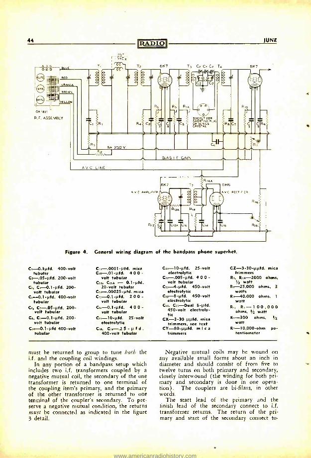
44
A D G 000
e H- OR 1851
R.F. ASSEMBLY
BjUE
RED
ORANGE
BROWN
YELLO
RADIO'
6K7
JUNE
6K7
SOCKET FOR SHORTING PLUG OR SERIES CRYSTAL
AV.C. LINE
B+ 250 V.
BIAS I F. GAIN
6H6
A V C RECTIFIER
T15
Figure 4. General wiring diagram of the bandpass phone superhet.
C,- 0.11.0d. 400 -volt C,1- .0001 -µfd. mica 020-10 -1.0d. 25 -volt CZ -3 -30 -µ0d. mica tubular C,2 -.01 -µfd. 4 0 0 - electrolytic trimmers
C2-.05 -µfd. 200 -volt volt tubular Cs,- .005 -0d. 4 0 0 - RI, R,e -2000 ohms, tubular Cs, C,as - 0.1 -µfd. volt tubular 12 watt
Ca, Ca-0.1 -0d. 200- 20 -volt tubular Css- -4 -1.fd. 450 -volt R:- 25,000 ohms, 3
volt tubular C,4- .00025 -µfd. mica electrolytic watts Cs-0.1 -0d. 400 -volt C,s -0.1 -µfd. 2 0 0 - C, -8 -µfd. 450 -volt R 40,000 ohms, 1
tubular volt tubular electrolytic watt Cs, C7-.05 -1fd. 200- C,s -0.l -µfd. 4 0 0 - Cu, Cis-Dual 8 -µfd. R,, R.-100 , 0 0 0
volt tubular volt tubular 450 -volt electroly- ohms, 12 watt C, ,3, Cs-0.1-0d. 200- C,1 -10- fd. 25 -volt
tic R. -300 ohms, 12 µ µ CX -3 -30 µµfd. mica
volt tubular electrolytic trimmers, see text watt C,o -0.1 -µfd 400 -volt C,,,, C,s-.2 5 - µ f d . CY-80 -µµfd. mica R-- 10,000 -ohm po-
tubular 400 -volt tubular trimmers tentiometer
must be returned to group to tune both the i.f. and the coupling coil windings.
In any portion of a bandpass setup which includes two i.f. transformers coupled by a negative mutual coil, the secondary of the one transformer is returned to one terminal of the coupling item's primary, and the primary of the other transformer is returned to one terminal of the coupler's secondary. To pre- serve a negative mutual condition, the returns must be connected as indicated in the figure 3 detail.
Negative mutual coils may be wound on any available small forms about an inch in diameter and should consist of from five to twelve turns on both primary and secondary, closely interwound (the winding for both pri- mary and secondary is done in one opera- tion) . The couplers are bi- filars, in other words.
The start lead of the primary and the finish lead of the secondary connect to i.f. transformer returns. The return of the pri- mary and start of the secondary connect to-
-4
w
www.americanradiohistory.com
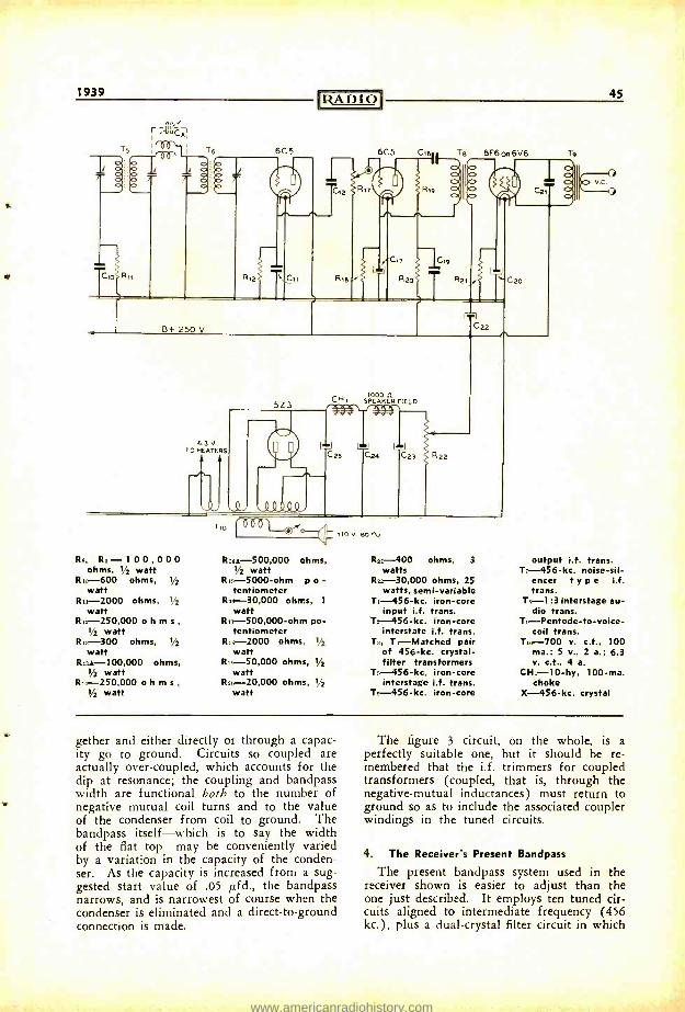
1939
tio ,tiüC%I
RADIO 45
v-c.
TO 63 V. HEATERS
5Z3 CH, 1000 11.
S PEAKER FIELD
C23 u
C24 u
C23 R22
Tio pÓO 110 V 80 1.
Rs, R,--I 0 0,0 0 0 Rise- 500,000 ohms, R21 -400 ohms, 3 output i.f. trans. ohms, 1/2 watt 1/2 watt watts T,- 456 -kc. noise -sil-
R, -600 ohms, 1/2 Ris -5000 -ohm p o - Ris 30,000 ohms, 25 encer t y p e i.f. watt tentiometer watts, semi -variable trans.
R -2000 ohms, y R,x- 30,000 ohms, 1 T,- 456 -kc. iron -core T8-1 :3 interstage au- watt watt input i.f. trans. dio trans.
R,2- 250,000 o h m s , R1,- 500,000 -ohm po- Ts- 456 -kc. iron -core To-Pentode-to-voice- 1/2 watt tentiometer interstate i.f. trans. coil trans.
Ri -300 ohms, 1/2 R.-2000 ohms, 1/2 T3, Ta- Matched pair T,0-700 v. c.t., 100 watt watt of 456 -kc. crystal- ma.; 5 v., 2 a.; 6.3
R,as- 100,000 ohms, 1/2 watt
Ru- 50,000 ohms, 1/2 filter transformers v. c.t., 4 a. watt T,,-456-kc. iron -core CH,- 10 -hy, 100 -ma.
R,8- 250,000 o h m s ,
1/2 watt R20- 20,000 ohms, I¡2 interstage i.f. trans. choke
watt To- 456 -kc. iron -core X- 456 -kc. crystal
gether and either directly or through a capac- ity go to ground. Circuits so coupled are actually over -coupled, which accounts for the dip at resonance; the coupling and bandpass width are functional both to the number of negative mutual coil turns and to the value of the condenser from coil to ground. The bandpass itself -which is to say the width of the flat top -may be conveniently varied by a variation in the capacity of the conden- ser. As the capacity is increased from a sug- gested start value of .05 pfd., the bandpass narrows, and is narrowest of course when the condenser is eliminated and a direct -to- ground connection is made.
The figure 3 circuit, on the whole, is a perfectly suitable one, but it should be re- membered that the i.f. trimmers for coupled transformers (coupled, that is, through the negative -mutual inductances) must return to ground so as to include the associated coupler windings in the tuned circuits.
4. The Receiver's Present Bandpass
The present bandpass system used in the receiver shown is easier to adjust than the one just described. It employs ten tuned cir- cuits aligned to intermediate frequency (456 kc.), plus a dual -crystal filter circuit in which
www.americanradiohistory.com
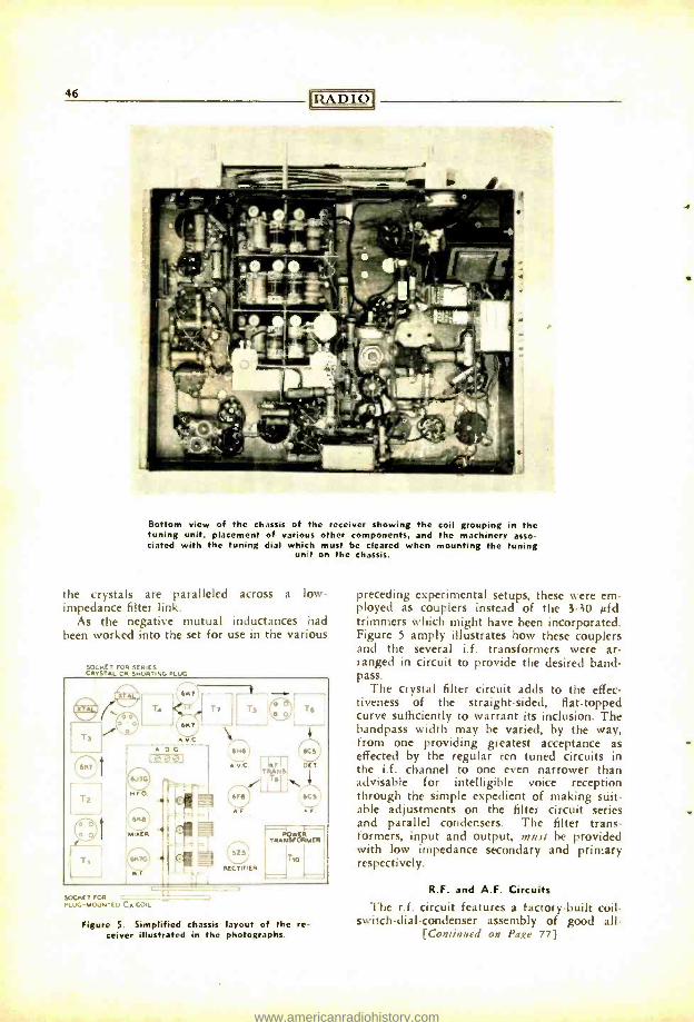
46 IZA I) I O
Bottom view of the chassis of the receiver showing the coil grouping in the tuning unit, placement of various other components, and the machinery asso- ciated with the tuning dial which must be cleared when mounting the tuning
unit on the chassis.
the crystals are paralleled across a loco
impedance filter link. As the negative mutual inductances had
been worked into the set for use in the various
SOCKET FOR SERIES CRYSTAL OR SNORTING PLUG
Tz
lese]
Nro
TT T! T6
606 j 6C!
AVC F161-1 I OCT TRANS
flT6l]` C6F6 6C!
Ar A r
GOwER RA NSrORMET:11
Ü T,o
RECTIFIER I
.
SOCKET FOR PLUG +MO.JNRL CA coil
7-73
Figure 5. Simplified chassis layout of the re- ceiver illustrated in the photographs.
preceding experimental setups, these were em- ployed as couplers instead of the 3 -30 µtd. trimmers which might have been incorporated. Figure 5 amply illustrates how these couplers and the several i.f. transformers were ar- ranged in circuit to provide the desired band - pass.
The crystal filter circuit adds to the effec- tiveness of the straight -sided, flat- topped curve sufficiently to warrant its inclusion. The Bandpass width may be varied, by the way, from one providing greatest acceptance as effected by the regular ten tuned circuits in the i.f. channel to one even narrower than advisable for intelligible voice reception through the simple expedient of making suit- able adjustments on the filter circuit series and parallel condensers. The filter trans- formers, input and output, must be provided with low impedance secondary and primary respectively.
R.F. and A.F. Circuits The r.f. circuit features a factory -built coil -
switch- dial -condenser assembly of good all - [Continued on Page 77)
www.americanradiohistory.com
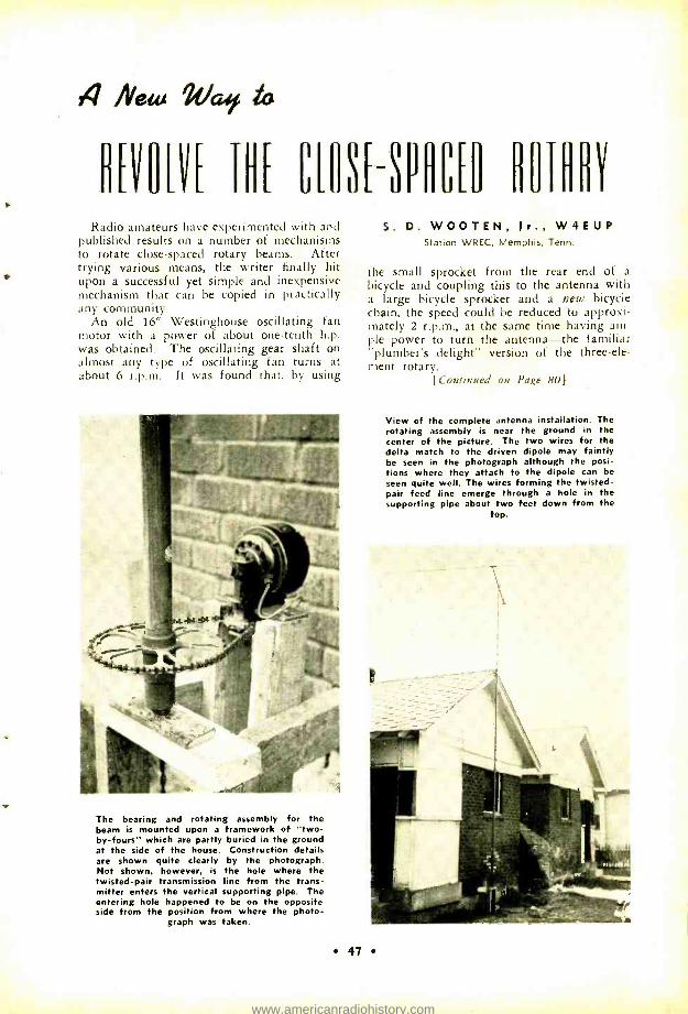
4 New It /at/ to
D[VOVE THE CM3ESPHC[D BOIflBV
Radio amateurs have experimented with and published results on a number of mechanisms to rotate close- spaced rotary beams. After trying various means, the writer finally hit upon a successful yet simple and inexpensive mechanism that can be copied in practically any community.
An old 16" Westinghouse oscillating fan motor with a power of about one -tenth h.p. was obtained. The oscillating gear shaft on almost any type of oscillating fan turns at about 6 r.p.m. It was found that, by using
The bearing and rotating assembly for the beam is mounted upon a framework of "two - by- fours" which are partly buried in the ground at the side of the house. Construction details are shown quite clearly by the photograph. Not shown, however, is the hole where the twisted -pair transmission line from the trans- mitter enters the vertical supporting pipe. The entering hole happened to be on the opposite side from the position from where the photo-
graph was taken.
S. D. WOOTEN, Jr., W4EUP Station WREC, Memphis, Tenn.
the small sprocket from the rear end of a
bicycle and coupling this to the antenna with a large bicycle sprocket and a new bicycle chain, the speed could be reduced to approxi- mately 2 r.p.m., at the same time having am- ple power to turn the antenna -the familiar "plumber's delight" version of the three-ele- ment rotary.
[Continued on Page 80)
View of the complete antenna installation. The rotating assembly is near the ground in the center of the picture. The two wires for the delta match to the driven dipole may faintly be seen in the photograph although the posi- tions where they attach to the dipole can be seen quite well. The wires forming the twisted - pair feed line emerge through a hole in the supporting pipe about two feet down from the
top.
47
www.americanradiohistory.com
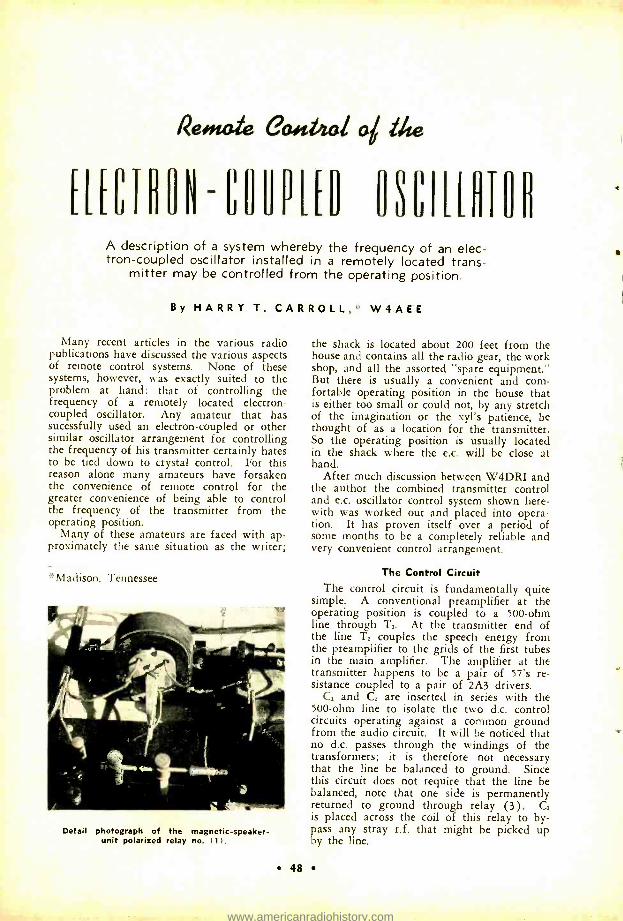
%lemaie eculbial iv.
[[EíTRHNHHPL[O USL'ILHTUR A description of a system whereby the frequency of an elec- tron- coupled oscillator installed in a remotely located trans-
mitter may be controlled from the operating position.
By HARRY T. CARROLL, ° W4AEE
Many recent articles in the various radio publications have discussed the various aspects of remote control systems. None of these systems, however, was exactly suited to the problem at hand: that of controlling the frequency of a remotely located electron - coupled oscillator. Any amateur that has sucessfully used an electron -coupled or other similar oscillator arrangement for controlling the frequency of his transmitter certainly hates to be tied down to crystal control. For this reason alone many amateurs have forsaken the convenience of remote control for the greater convenience of being able to control the frequency of the transmitter from the operating position.
Many of these amateurs are faced with ap- proximately the same situation as the writer;
`Madison, Tennessee
Detail photograph of the magnetic- speaker- unit polarized relay no. i 1 ) .
48
the shack is located about 200 feet from the house and contains all the radio gear, the work shop, and all the assorted "spare equipment." But there is usually a convenient and com- fortable operating position in the house that is either too small or could not, by any stretch of the imagination or the xyl's patience, be thought of as a location for the transmitter. So the operating position is usually located in the shack where the e.c. will be close at hand.
After much discussion between W4DRI and the author the combined transmitter control and e.c. oscillator control system shown here- with was worked out and placed into opera- tion. It has proven itself over a period of some months to be a completely reliable and very convenient control arrangement.
The Control Circuit The control circuit is fundamentally quite
simple. A conventional preamplifier at the operating position is coupled to a 500 -ohm line through L. At the transmitter end of the line T2 couples the speech energy from the preamplifier to the grids of the first tubes in the main amplifier. The amplifier at the transmitter happens to be a pair of 57's re- sistance coupled to a pair of 2A3 drivers.
C, and C2 are inserted in series with the 500 -ohm line to isolate the two d.c. control circuits operating against a common ground from the audio circuit. It will be noticed that no d.c. passes through the windings of the transformers; it is therefore not necessary that the line be balanced to ground. Since this circuit does not require that the line be balanced, note that one side is permanently returned to ground through relay (3). C2 is placed across the coil of this relay to by- pass any stray r.f. that might be picked up by the line.
www.americanradiohistory.com
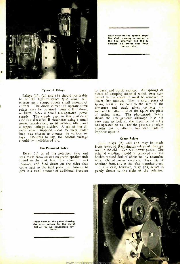
Types of Relays
Relays (1), (2) and (3) should preferably be of the high- resistance type which will operate on a comparatively small amount of current. The direct current to operate these relays may be obtained from a B battery, or better from a small a.c.- operated power supply. The supply used in this particular case is a discarded B eliminator using a small power transformer, an 80 rectifier, filter, and a tapped voltage divider. A tap of the di- vider which supplied about 25 volts under load was chosen to operate the various re- lays. Needless to say, the control voltage should be well -filtered d.c.
The Polarized Relay
Relay (1) is of the polarized type and was made from an old magnetic speaker unit found in the junk box. The armature was removed and filed down on the sides that come next to the field poles just enough to give it a small amount of additional freedom
Front view of the panel showing the drive system for the metal dial on the e.c. bandspread con-
denser.
Rear view of the speech ampli- fier deck showing a portion of the line amplifier and the re- versible a.c. motor that drives
the e.c. dial.
to back and forth motion. All springs or pieces of damping material which were con- nected to the armature must be removed to insure free motion. Then a short piece of spring brass is soldered to the arm of the armature and small silver contacts are soldered to either side of the tip of the piece of spring brass. The photograph clearly shows the arrangement; although it is not very neat to look at, the experimental relay has operated so well for the past six or eight months that no attempt has been made to improve upon it.
Other Relays
Both relays (2) and (3) may be made from rewound B- eliminator relays of the type used in the old Philco A -B power packs. The original winding should be removed and the bobbin wound full of about no. 32 enameled wire. Or, of course, excellent relays may be obtained from any of the relay manufacturers.
In this case, however, relay (2), which is partly shown to the right of the polarized
www.americanradiohistory.com
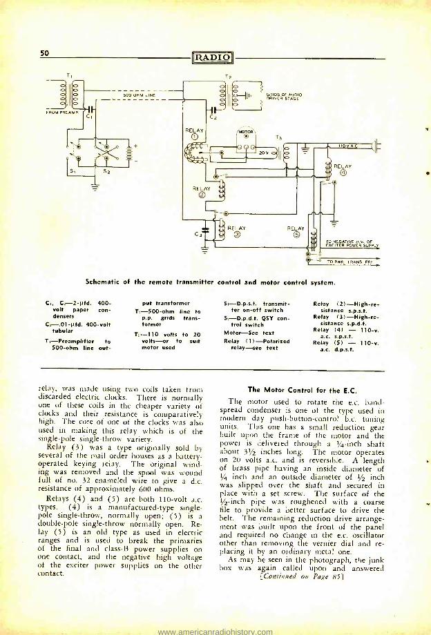
50
FROM PREAMP.
500 OHM LINE
IZADIO1
2
T2
GRIDS OF AUDIO DRIVER STAGE
Cc.
b
RELAY 2
RELAY RELAY
110 V A.0
RELAY
:-O
TO NEGATIVE H.V. OF EXCITER POWER SUPPL`
TO PWR. TRANS. PRI.
Schematic of the remote transmitter control and motor control system.
C1, C1-2 -µfd. 400- put transformer volt paper con- 7,-500-ohm line to densers p.p. grids trans -
C:-.01 -µfd. 400 -volt former tubular
T1- Preamplifier to 500 -ohm line out-
T:, 110 volts to 20 volts -or to suit motor used
S1- D.p.s.t. transmit- ter on -off switch
QSY con- trol switch
Motor -See text Relay (1 ) -Polarized
relay -see text
Relay (2) -High -re- sistance s.p.s.t.
Relay ( 3 ) -High -re- sistance s.p.d.t.
Relay (4) - 110 -v. a.c. s.p.s.t.
Relay (5) - 110 -v. a.c. d.p.s.t.
relay, was made using two coils taken from discarded electric clocks. There is normally one of these coils in the cheaper variety of clocks and their resistance is comparatively high. The core of one of the clocks was also used in making this relay which is of the single -pole single -throw variety.
Relay (3) was a type originally sold by several of the mail order houses as a battery - operated keying relay. The original wind- ing was removed and the spool was wound full of no. 32 enameled wire to give a d.c. resistance of approximately 600 ohms.
Relays (4) and (5) are both 110 -volt a.c. types. (4) is a manufactured -type single - pole single- throw, normally open; (5) is a double -pole single -throw normally open. Re- lay (5) is an old type as used in electric ranges and is used to break the primaries of the final and class -B power supplies on one contact, and the negative high voltage of the exciter power supplies on the other contact.
The Motor Control for the E.C.
The motor used to rotate the e.c. band - spread condenser is one of the type used in modern day push -button- control b.c. tuning units. This one has a small reduction gear built upon the frame of the motor and the power is delivered through a 1/4 -inch shaft about 31/2 inches long. The motor operates on 20 volts a.c. and is reversible. A length of brass pipe having an inside diameter of 1/4 inch and an outside diameter of 1/2 inch was slipped over the shaft and secured in place with a set screw. The surface of the 1/2 -inch pipe was roughened with a coarse file to provide a better surface to drive the belt. The remaining reduction drive arrange- ment was built upon the front of the panel and required no change in the e.c. oscillator other than removing the vernier dial and re- placing it by an ordinary metal one.
As may be seen in the photograph, the junk box was again called upon and answered
[Continued on Page 85)
www.americanradiohistory.com
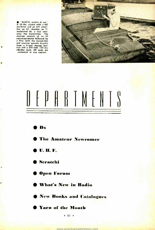
"W2KTC, mobile at sea." A 28 -Mc. crystal with a 615 oscillator and an 807 ampli- fier on 10 doubler on 51 modulated by a 6L6 com- prise the transmitter. The receiver consists of an 89 superregenerator followed by a 6V6; both the transmitter and receiver operate directly from a 6 -volt storage bat- tery and a 300 -volt, 100 -ma. vibrator pack. All units are
contained in one cabinet.
V ENTS
DY
The Amateur Newcomer
U. II. F.
Scratclii
Open Forum
What's New in Radio
New Books and Catalogues
Yarn of the Month 51
www.americanradiohistory.com
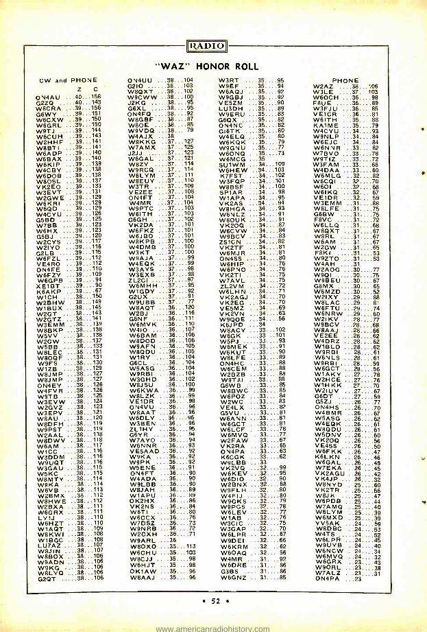
[RADIO
"WAZ" HONOR ROLL
CW and PHONE ON4UU 38...104 W3RT ....35....95 PHONE Z C G210 38...103
W8QXT 38...102 W9EF ....35....94 W6AQJ ...35....92
W2AZ ....38...106 W3LE ....37...103
ON4AU ...40...158 W9CWW 38...100 W9GBJ ...35....92 W6OCH ...36....98 G2ZQ 40...143 J2 KG .....38....95 VE5ZM ...35....90 F8UE 36....89 W8CRA ...39...156 G6XL 38....95 LU3DH ...35....89 W3FJU ...36....85 G6WY ....39...151 ON4FQ 38....92 W9ERU ...35....83 VE1CR ...36....81 W6CXW ..39...150 W8GBF 38....87 G6QX 35....82 W6ITH ...35....88 W6GRL ...39...150 W8OE ....38. ... 85 ON4NC 35....82 KA1ME ...35....79 W9TJ 39. .144 W9VDQ ...38....79 GI6TK ....35....80 W4CYU ...34....93 W6CUH 39...143 W4AJX ...38 W4ELQ ...35....80 W9NLP ...34....84 W2HHF 39...141 W8KKG ..37...127 W6KQK ..35....79 W6EJC ...34....84 W8BTI 39...141 W7AMX ..37...125 W9GNU ..35....77 W6NNR ..33....82 W6ADP 39...140 J2JJ 37...123 W6ONQ ...35....73 W76V0 ...33....78 W6BAX ...39...140 W6GAL .37... 121 W6MCG ...35 W9TIZ ....33....72 W6KIP ...39...139 W8ZY 37...114 SU1WM ...34...109 W3FAM ...33....68 W4CBY ...39...138 W9RCQ 37...114 W6HEW ..34...103 W4DAA ...33....60 W6DOB ...39...138 W6LVM 37...111 K7FST ...34...102 W6MLG ..32....82 W8OSL ...39...137 W8EUY 37...110 W3FQP ...34...101 W6CQI ....32....7U VK2E0 ...39...133 W3TR 37...109 W8BSF ...34...100 W601 32....68 W3EVT ...39...131 VE2EE ...37...108 SP1AR ...34....98 W61KQ 32....67 W2GWE ..39...129 ON4FT ...37...104 W1APA ...34....95 VE1DR 32....59 W6KR1 ...39...129 W4MR ...37...104 VK2AS ...34....94 W3EMM 31....88 W6QD ....39...129 W9PTC ...37...103 W8HGA ...34....93 W8LFE 31....75 W4CYU ...39...126 W6ITH ...37...103 W6NLZ ...34....91 G6BW 31....75 G5BD 39...125 G6GH 37...102 W8OUK ...34....91 F8VC 31....72 W7 BB ....39...123 VK2DA ...37...101 VK2OQ ...34....87 W6LLQ 31....68 W6HX ....39...123 W6FKZ ...37...101 W6CVW ..34....84 W8QXT 31....67 G5BJ 39..,120 W6JBO ...37...101 W9BCV ...34....83 W8 RL ....31....67 W2CYS 39...117 W8KPB ...37...100 ZS1CN ....34.... 82 W6AM ....31....67 W2IYO 39...116 W4DMB ..37...100 VK2TF ...34....81 W2GW ....31....65 G2LB 39...115 W3 KT ....37...100 W6MJR ...34....81 F8K1 .....31....53 W6FZL 39... 112 W9AJA ...37....99 ON4SS ....34....80 W9ZTO ...31....53 VE4RO 39...112 W4EQK ...37....99 W6HIP ...34....76 W4AH ....31 ON4FE 39...110 W3AYS ...37....98 W6PNO ...34....76 W2AOG ...30....77 W6FZY 39...109 W3EXB ...37....98 VK2TI ....34....75 W9QI 30....75 W6GPB ..39....94 ZL2CI 37....97 W7AVL ...34....75 W9BEU ...30....67 XE1BT ....39....90 W6MHH 37....95 ZL2VM ...34....72 G8MX 30....65 K6AKP ...39....67 W1GDY ...37....92 W6LHN ...34....71 W6MZD 30....52 W1CH ....38...150 G2UX 37....91 VK2AGJ ..34....70 W2IXY ...29....88 W2BHW ..38...149 W9UBB 37....77 VK2EG ...34....70 W8LAC ...29....81 W1BUX ...38...145 W8AQT 36...120 VE5MZ ...34....69 W6FTU ...29....74 W2GT ....38...143 W2BJ 36. .116 VK2VN ...34....63 W6NRW ..29....60 W2GTZ ...38...141 G6NF 36. .111 W9QOE ...34....56 W21 KV ...28....77 W3EMM ..38...139 W6MVK 36...110 K6JPD ...34 W9BCV ...28....6R W8BKP ...38...138 W410 36. .107 W8ACY ...33...102 W8AAJ ...28....66 W5VV ....38...138 W6BAM 36...106 W6GK ....33...101 VE2EE ...28....62 W2GW . ...38...137 W8DOD 36...106 WSPJ 33... .93 W4DRZ . ..28....62 W5BB ....38...133 W9AFN ...36...105 W6MEK 33....91 W16 L0 ...28....62 W8LEC ...38...131 W8QDU ...36...105 W6KUT 33....90 W9RBI ...28....61 W80QF ...38...131 WIRY ....36...104 WSLFE 33....89 W6NLS ...28....61 W9FS ....38...130 G6CL 36. .104 ON4HC ...33....88 W9RB1 ....28....59 W1ZB ....38...129 W5ASG 36...104 W6CEM ..33....88 W6GCT ...28....56 W8JMP ...38...127 W9RBI 36...104 W2BZB ...33....88 W1AKY ...27....78 W8JMP ...38...127 W3GHD 36...102 W9TJ.1 ...33....88 W2HCE ...27....76 ON4EY ...38... 126 W8JSU 36...100 G6WB ....33....85 W1HKK ..27....70 W4FVR ...38...126 W6KWA 36....99 W8BWC ..33....85 W2IUV ...27....67 W9TB ....38...125 W8LZK 36....99 W6POZ ...33....84 G6DT .....27....59 W3EVW ..38...124 VE1DR 36....98 W2WC ...33....83 G5ZJ .....26....77 W2GVZ ...38...123 ON4VU 36....96 VE4LX ...33....82 ON4HS ...26....70 W3EPV ...38...121 W8AAT 36....96 G5VU 33....81 W4BMR ..26....67 W8AU ....38...120 W6DLY ...36....96 W6ANN 33....81 W5ASG ...26....62 W8DFH ...38...119 W3BEN ...36....96 W6GCT 33....81 W4EQK ...26....61 W9PST ...38...119 ZL1HY ...36....95 W6LCF 33....78 W8QDU ...26....61 W2AAL ...38...118 G6YR 36....94 W6MVQ ..33....77 W5DNV ...26....60 W8DWV ..38...118 W7AYO 36....94 W2FAW ..33....67 VK20Q ...26....56 W6AM ....38...117 W6NNR 36....93 VK2RA ...33....65 VE4SS ....26....50 W1CC ....38...116 VE5AAD 36....92 ON4PA ...33....63 W6FKK ..26....47 W3DDM ..38...116 W9KA 36....92 K6CGK ...33....62 K6LKN ...26....46 W9UQT ..38...116 W9PK 36....92 W9LBB ...33 W6GAL ...26....45 W3GAU ...38...115 WSENE 36....91 VK2VQ ...32....99 W7EKA ..26....45 W5 KC ....38...115 ON4FT 36....90 W6KEV ...32....95 VK2AGU ..26....42 W8MTY ...38...114 W4ADA 36....90 W6DIO ...32....90 VK4JP ....26....32 W9KA ....38...114 W9LBB 36....90 W2BNX ...32....88 W8NYD ..25....60 W6VB ....38...113 W8JAH 36....89 W9FLH ...32....80 VK2TR ...25....56 W2BMX ..38...112 W1APU 36....89 W4FIJ ....32....80 W8JK ....25....47 W8HWE ..38...112 OK2HX 36....86 W9GKS ...32....79 W6PDB ...25....44 W2BXA ...38...111 VK2NS 36....84 W9PGS ...32....78 W7AMQ ..25....40 W6GRX ...38...111 W6T1 . 36....80 W6LEV ...32....77 W6LVM ..25....39 LY1J 38...110 W6GCX ...36....76 W1AB ....32....76 W6MXD ..25....39 W6HZT 38...110 W7DSZ ...36....73 W3CIC ....32....75 YV5AK ...24....59 W1AQT 38...109 W9NRB ...36....72 W3GAP ...32....70 W8DBC ..24....53 W8KWI 38...108 W2GXH ..36....71 W6LPR ...32....67 W4TS 24....52 W1BGC ...38 ..108 W9ARL ...36 W9DE1 ...32....66 W6LPR 24....45 LU7AZ ....38...107 W8OXO ...35...113 W6KRM ..32....62 W9UYB 24....40 W8JIN ....38...107 W6GHU W6OAQ W6NCW 24....34 W8BOX ...38... 106 ...35...103
W8CJJ ...32....56
W4MR W6MVQ 24....32 W9ADN ...38...106 ....35....98 ....31....92 W6GRX 23....43 W9 KG ....38...106 W6HJT ...35....98 W6DRE ...31....86 W9ORL 23....38 W8LYQ ...38...106 G2QT 38...106
OK1AW ...35....96 W8AAJ ...35....96
G3BS 31....86 W6GNZ 31....85
W7ALZ 23....31 ON4PA ...23
52
www.americanradiohistory.com
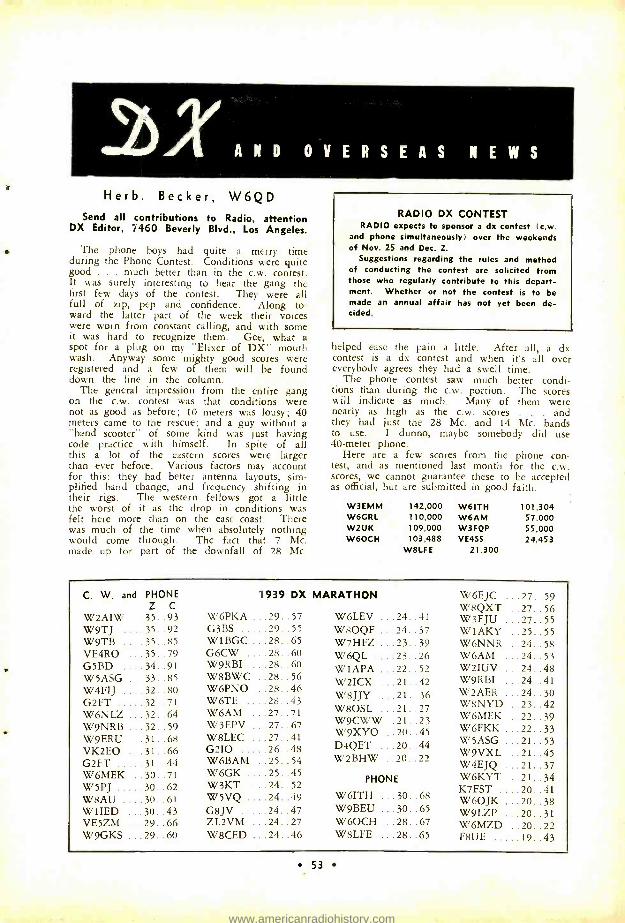
A N D asol4/T O V E R S E A S N E W S
Herb. Becker, W6QD Send all contributions to Radio, attention
DX Editor, 7460 Beverly Blvd., Los Angeles.
The phone boys had quite a merry time during the Phone Contest. Conditions were quite good . . . much better than in the c.w. contest. It was surely interesting to hear the gang the first few days of the contest. They were all full of zip, pep and confidence. Along to- ward the latter part of the week their voices were worn from constant calling, and with some it was hard to recognize them. Gee, what a spot for a plug on my "Elixer of DX" mouth wash. Anyway some mighty good scores were registered and a few of them will be found down the line in the column.
The general impression from the entire gang on the c.w. contest was that conditions were not as good as before; 10 meters was lousy; 40 meters came to the rescue; and a guy without a "band scooter" of some kind was just having code practice with himself. In spite of all this a lot of the eastern scores were larger than ever before. Various factors may account for this: they had better antenna layouts, sim- plified band change, and frequency shifting in their rigs. The western fellows got a little the worst of it as the drop in conditions was felt here more than on the east coast. There was much of the time when absolutely nothing would come through. The fact that 7 Mc. made up for part of the downfall of 28 Mc.
RADIO DX CONTEST RADIO expects to sponsor a dx contest (c.w.
and phone simultaneously) over the weekends of Nov. 25 and Dec. 2.
Suggestions regarding the rules and method of conducting the contest are solicited from those who regularly contribute to this depart- ment. Whether or not the contest is to be made an annual affair has not yet been de- cided.
helped ease the pain a little. After all, a dx contest is a dx contest and when it's all over everybody agrees they had a swell time.
The phone contest saw much better condi- tions than during the c.w. portion. The scores will indicate as much. Many of them were nearly as high as the c.w. scores . and they had just the 28 Mc. and 14 Mc. bands to use. I dunno, maybe somebody did use 40 -meter phone.
Here are a few scores from the phone con- test, and as mentioned last month for the c.w. scores, we cannot guarantee these to be accepted as official, but are submitted in good faith.
W3EMM W6GRL W2UK W 6OC H
142,000 W6ITH 110,000 W6AM 109,000 W3FQP 103,488 VE4SS
W8LFE 21,300
101,304 57,000 55,000 24,453
C. W. and PHONE Z C
W2AIW 35. 93 W9TJ 35..92 W9TB 35..85 VE4RO . . 35 . . 79 G5BD . . . 34. .91 W5ASG 33..85
W4FIJ 32..80
G2FT 32. .71 W6NLZ 32..64 W9NRB 32..59 W9ERU 31..68 VK2EO . . 31 . . 66 G2FT 31 . .44 W6MEK 30..71 W5PJ 30..62 W8AU 30..61 W1IED 30..43 VE5ZM 29..66 W9GKS 29..60
1939 DX MARATHON
W6PKA 29..57 G3BS 29..55 WIBGC . 28..65 G6CW 28..60 W9RBI . . 28 . . 60 W8BWC 28..56 W6PNO . 28. .46 W6TE 28..43 W6AM 27..71 W3EPV 27..67 W8LEC 27..41 G2I0 26..48 W6BAM 25..54 W6GK 25..45 W3KT 24..52 W5VQ 24..49 G8JV 24..47 ZL2VM 24..27 W8CED 24..46
W6LEV ...24..41 W8OQF ...24. .37 W7HFZ ...23..39 W6QL ....23..26 W1APA ...22..52 W2ICX ...21..42 W8JJY ...21..36 W8OSL ...21..27 W9CWW .21..23 W9XYO . . 20. .45 D4QET ...20..44 W2BHW ..20..22
PHONE
W6ITH ...30..68 W9BEU ...30..65 W6OCH ..28..67 W8LFE ...28..65
W6EJC ...27..59 W8QXT ..27..56 W3FJU ...27..55 W1AKY ..25..55 W6NNR ..24..58 W6AM ...24..53 W2IUV ...24..48 W9RBI . . .24. .41 W2AER ...24..30 W8NYD ..23..42 W6MEK ..22..39 W6FKK ...22..33 W5ASG ...21..53 W9VXL ..21..45 W4EJQ ...21..37 W6KYT ..21..34 K7FST ....20..41 W6OJK ...20..38 W9LZP ...20..31 W6MZD ..20..22 F8UE 19. .43
53
www.americanradiohistory.com
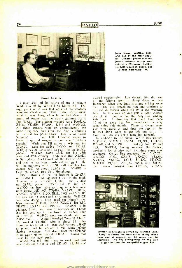
54 IRADIOI JUNE
Phone Chatter
I must start off by telling of the 27- minute WAC run off by W6FTU on March 24. The high point of it was that none of the contacts were on schedule and "Doc" didn't really know what he was doing when he worked them. I mean, of course, that he wasn't gunning for a fast WAC. The stations worked were PAOUN, ZS4H, VK3EH, PY2AC, J2MI and W6MLG. All these stations were on approximately the same frequency and after the first 3 contacts he realized his possibilities. Doc is an "Oral Surgeon" . . . and little Hortense wants to know if an oral surgeon is one who "butchers speech." With that I'll go to a W9 and it's W9RBI. Ross has added PK4KS and PK1RI. W4EJQ has 21 zones and 42 countries on 28 -Mc. phone. W6FKK grabs ES5D for his 26th zone and 47th country. FKK says that XU8DI is Sgt. Major MacDonnel of the British Army, and that he has been transferred to Egypt. He will be on there with an SU call and his fre- quency will be about 14,378 kc. VS6BE is Capt. Whatman, Box 651, Hongkong.
F8VC informs us that his brother is CN8BA on 14,061 kc. His rig uses a 211 in the final. Antenna is a full -wave Hertz. He is also on 28 -Mc. phone. F8VC has 31 and 72. W6IKQ has been able to drag in a few new ones lately: HK1AG, TG9BA, VK9VG, HR2A, VK9DK, VP6YB, EI2Q, EI2L, J8CI and YNIIP. He now has 32 zones and 67 countries. W2HCE has been doing a little good for himself too. New ones are OH2OI, PK4KS, XZ2DY, EA7RM, PK3WI, LX1AI and VP2LC. EA7RM is in Malaga, Spain, and usually operates on 14,800 k.c. but gets up in the band on 14,260 once in a while. W2HCE says we should start an AWZ 23C.. . "Almost Worked Zone 23 Club." He worked VU2BG, who is about 15 miles from the border of 23. Bill said he saw 2HHF at school and he worked a VK while asleep during the contest. Bill also relates that CN1AF is on again under the call EK1AF. Guess that must be the new prefix.
W3LE can still find them to work and two new ones are CR4GO and ZK1AZ, 14,136 and
John Serwe, W6NLS, oper- ates one of the most popu- lar 10 -meter phone stations. John's antenna set -up con- sists of a 21/4 -wave rhombic, six half waves in phase, and
a four half -wave "H."
14,386 respectively. Lou doesn't like the way all the fellows seem to clamp down on one frequency when they hear this guy calling some dx. They shift smack on him and continue to call the dx station while the W is still working him. In this way no one gets a good contact out of it. - Lou is not the only one voicing this idea. I dare say that there have been 50 of the gang that have mentioned the very same thing this month. There is always some guy who starts it and then the rest of the fellows don't want to get left out so . . .
from then on it's every man for himself. In addition to the above, W3LE has worked
VQ5KTF, YU7XU, EA9AH, VQ2PL, HR1AT, FT4AR and VP1ZK . . . making him 37 and 103. W6ITH, having survived the contest, worked a lot of nice stuff including some new countries. On 20 Reg contacted J8CI, VK7CM, XZ2DX, EI2L, XZ2JB, VK9DK, VS2AK, NY1AA, VS6BD, LY1S, SP1DC, PK6XX, XU7TH, VQ2PL, ZEIJX, ES5D, and SM5SI. Ten meters brought him CN8BA, VP3AA,
W9NLP in Chicago is owned by Rowland Long. "Roily" is among the most active of the phone boys and at present has 34 zones and 84 countries. The fire extinguisher on the wall
is just in case the competition gets hot.
www.americanradiohistory.com
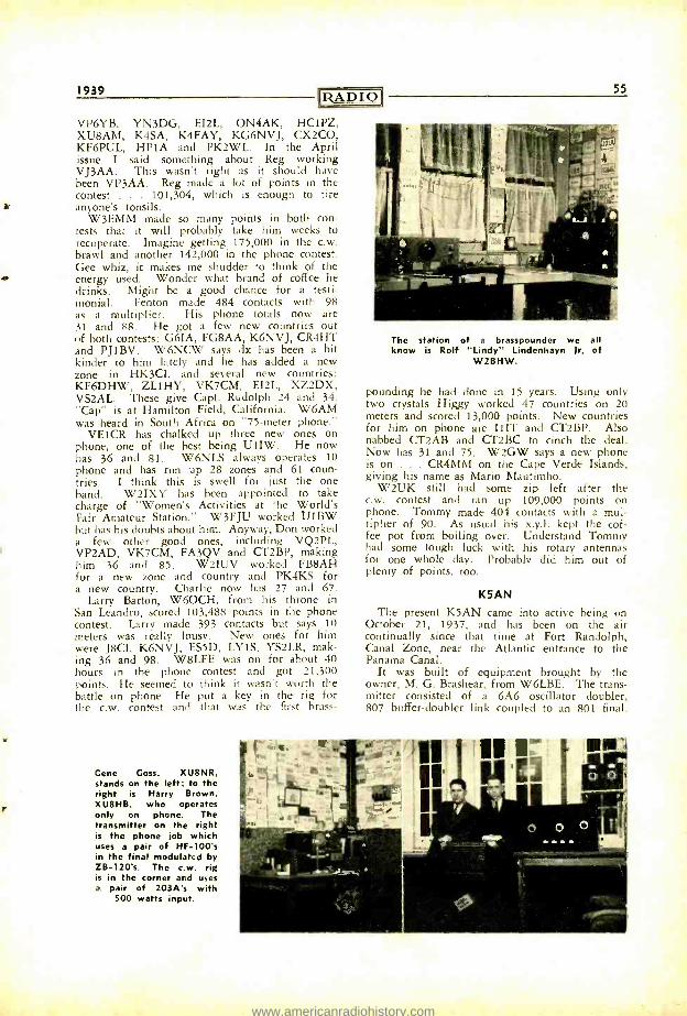
1939 RADIO
VP6YB, YN3DG, EI2L, ON4AK, HC1PZ, XU8AM, K4SA, K4FAY, KG6NVJ, CX2CO, KF6PUL, HP1A and PK2WL. In the April issue I said something about Reg working VJ3AA. This wasn't right as it should have been VP3AA. Reg made a lot of points in the contest . . . 101,304, which is enough to tire anyone's tonsils.
W3EMM made so many points in both con- tests that it will probably take him weeks to recuperate. Imagine getting 175,000 in the c.w. brawl and another 142,000 in the phone contest. Gee whiz, it makes me shudder to think of the energy used. Wonder what brand of coffee he drinks. Might be a good chance for a testi- monial. Fenton made 484 contacts with 98 as a multiplier. His phone totals now are 31 and 88. He got a few new countries out of both contests: G6IA, FG8AA, K6NVJ, CR4HT and PJ1BV. W6NCW says dx has been a bit kinder to him lately and he has added a new zone in HK3CL and several new countries: KF6DHW, ZL1HY, VK7CM, EI2L, XZ2DX, VS2AL. These give Capt. Rudolph 24 and 34. "Cap" is at Hamilton Field, California. W6AM was heard in South Africa on "75 -meter phone."
VE1CR has chalked up three new ones on phone, one of the best being UlIW. He now has 36 and 81. W6NLS always operates 10 phone and has run up 28 zones and 61 coun- tries. I think this is swell for just the one hand. W2IXY has been appointed to take charge of "Women's Activities at the World's Fair Amateur Station." W3FJU worked UIBW but has his doubts about him. Anyway, Don worked a few other good ones, including VQ2PL, VP2AD, VK7CM, FA3QV and CT2BP, making him 36 and 85. W2IUV worked FB8AH for a new zone and country and PK4KS for a new country. Charlie now has 27 and 67.
Larry Barton, W6OCH, from his throne in San Leandro, scored 103,488 points in the phone contest. Larry made 393 contacts but says 10 meters was really lousy. New ones for him were JBCI, K6NVJ, ES5D, LY1S, YS2LR, mak- ing 36 and 98. W8LFE was on for about 40 hours in the phone contest and got 21,300 points. He seemed to think it wasn't worth the battle on phone. He put a key in the rig for the c.w. contest and that was the first brass-
Gene Goss, XU8NR, stands on the left; to the right is Harry Brown, XU8HB. who operates only on phone. The transmitter on the right is the phone job which uses a pair of HF -100's in the final modulated by ZB- 120's. The c.w. rig is in the corner and uses a pair of 203A's with
500 watts input.
55
The station of a brasspounder we all know is Rolf "Lindy" Lindenhayn Jr. of
W2BHW.
pounding he had done in 15 years. Using only two crystals Higgy worked 47 countries on 20 meters and scored 13,000 points. New countries for him on phone are IIIT and CT2BP. Also nabbed CT2AB and CT2BC to cinch the deal. Now has 31 and 75. W2GW says a new phone is on . CR4MM on the Cape Verde Islands, giving his name as Mario Mautimho.
W2UK still had some zip left after the c.w. contest and ran up 109,000 points on phone. Tommy made 404 contacts with a mul- tiplier of 90. As usual his x.y.l. kept the cof- fee pot from boiling over. Understand Tommy had some tough luck with his rotary antennas for one whole day. Probably did him out of plenty of points, too.
K5AN
The present K5AN came into active being on October 21, 1937, and has been on the air continually since that time at Fort Randolph, Canal Zone, near the Atlantic entrance to the Panama Canal.
It was built of equipment brought by the owner, M. G. Brashear, from W6LBE. The trans- mitter consisted of a 6A6 oscillator doubler, 807 buffer -doubler link coupled to an 801 final.
www.americanradiohistory.com
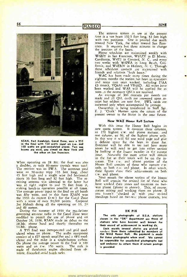
56 RADIO
K5AN, Fort Randolph, Canal Zone, uses a T55 in the final with 150 watts input on c.w. and 100 watts on grid -modulated phone. Two vee beams are used, one aimed on New York and
the other on San Francisco.
When operating on 28 Mc. the final was also a doubler, as only 80 -meter crystals were used. The receiver was an SW -3. The antennas used were an 80 -meter zepp 133 feet long, about 45 feet high and a single wire fed horizontal Hertz 33 feet long and 32 feet high. The re- ceiving antenna was identical to the latter but was at right angles to and 75 feet from it, making break -in operation possible at all times. The average power input to the final on all bands was fifty watts, and in this form K5AN won the 1938 dx contest (c.w.) for the Canal Zone with a score of over 94,000 points. Corporal Joe Hybach doing all the operating on 10, 20 and 40 meters.
During the summer of 1938 the regulations governing amateur radio in the Canal Zone were modified to permit the use of phone and on October 26, 1938, K5AN made its debut on the 28 -Mc. phone band and shortly thereafter on 14 -Mc. phone.
A T55 final was incorporated and grid mod- ulated when on phone. The audio equipment consists of a 6J7 speech amplifier and a 6F6 mod- ulator and the mike is a single- button carbon. On phone the average power to the final is 100 watts and on c.w. 150 watts. The rack is made of duralumin angles obtained from ob- solete, discarded aerial bomb racks.
1UNE
The antenna system in use at the present time is a vee beam 132.5 feet long, 32 feet high with two positions. One is pointed due north toward New York, the other toward San Fran- cisco. It requires but three minutes to change the position of the beam.
Phone schedules are maintained weekly with W6BIY in San Francisco, W6LZV in El Monte, Canifornia, W4TJ in Concord, N. C., and every two weeks with W6PFA in Long Beach, Cali- fornia, and W4EMV in Hickory, N. C. Through these schedules contacts are maintained with friends and relatives "back home."
WAC has been made many times during the eighteen months the station has been in operation and some rare ones worked, including I7AA (3 times), VQ8AS and VR4AD. All states have been worked and WAS will be applied for as soon as the necessary QSL's are received.
An average of 300 contacts per month are made and all QSL cards are answered upon re- ceipt but seldom are sent first. SWL cards are answered only when accompanied by postage.
Ownership is being transferred to Staff Sgt. E. J. "Chick" Hansen upon the return of the present owner to the States in the near future.
New WAZ Honor Roll System
With this issue the Honor Roll begins its new quota system. It contains three columns, or 270 highest c.w. and phone stations; and one column, or 90, of the highest phone only. In this way it will fill one solid page and give a definite space for the boys to shoot for. Everyone will be able to see just how many zones he will need to get into either section by looking at the lowest number in the current issue. Naturally the most active will remain in the list as their totals will be on the in- crease. The c.w. and phone portion of the Honor Roll consists of those who operate c.w. only, or both c.w. and phone. In other words, these figures show their achievements on both c.w. and phone.
Next month the phone section of the Honor Roll will contain the revised list of those who have worked their zones and countries on two - way phone (phone to phone). This, of course, means raising and working them on phone. If you haven't "checked in" with your revised standings based on two -way phone contacts, you
DX PIX The only photographs of U.S.A. stations
shown in the "DX" department are those of stations who have become well known for their record of achievement in working dx.
Each month several photos are picked at mdo, from those submitted by members of
the WAZ Honor Roll. No payment is made for these photographs when used. We cannot be responsible for unsolicited photographs but will endeavor to return them if return postage is provided.
www.americanradiohistory.com
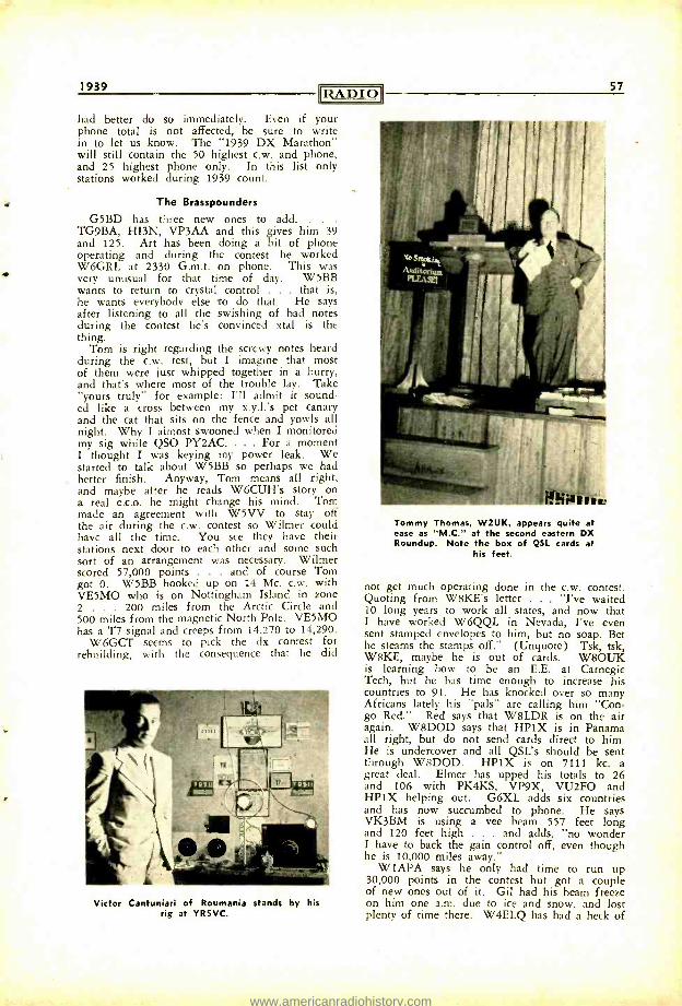
1939 RADIO had better do so immediately. Even if your phone total is not affected, be sure to write in to let us know. The "1939 DX Marathon" will still contain the 50 highest c.w. and phone, and 25 highest phone only. In this list only stations worked during 1939 count.
The Brasspounders G5BD has three new ones to add.
TG9BA, HI3N, VP3AA and this gives him 39 and 125. Art has been doing a bit of phone operating and during the contest he worked W6GRL at 2330 G.m.t. on phone. This was very unusual for that time of day. W5BB wants to return to crystal control . . . that is, he wants everybody else to do that. He says after listening to all the swishing of bad notes during the contest he's convinced xtal is the thing.
Tom is right regarding the screwy notes heard during the c.w. test, but I imagine that most of them were just whipped together in a hurry, and that's where most of the trouble lay. Take "yours truly" for example: I'll admit it sound- ed like a cross between my x.y.l.'s pet canary and the cat that sits on the fence and yowls all night. Why I almost swooned when I monitored my sig while QSO PY2AC. ... For a moment I thought I was keying my power leak. We started to talk about W5BB so perhaps we had better finish. Anyway, Tom means all right, and maybe atter he reads W6CUH's story on a real e.c.o. he might change his mind. Tom made an agreement with W5VV to stay off the air during the c.w. contest so Wilmer could have all the time. You see they have their stations next door to each other and some such sort of an arrangement was necessary. Wilmer scored 57,000 points . . . and of course Tom got 0. W5BB hooked up on 14 Mc. c.w. with VE5MO who is on Nottingham Island in zone 2 . 200 miles from the Arctic Circle and 500 miles from the magnetic North Pole. VE5MO has a T7 signal and creeps from 14,270 to 14,290.
W6GCT seems to pick the dx contest for rebuilding, with the consequence that he did
Victor Cantuniari of Roumania stands by his rig at YR5VC.
57
Tommy Thomas, W2UK, appears quite at ease as "M.C." at the second eastern DX Roundup. Note the box of QSL cards at
his feet.
not get much operating done in the c.w. contest. Quoting from W8KE's letter . . . "I've waited 10 long years to work all states, and now that I have worked W6QQL in Nevada, I've even sent stamped envelopes to him, but no soap. Bet he steams the stamps off." (Unquote) Tsk, tsk, W8KE, maybe he is out of cards. W8OUK is learning how to be an E.E. at Carnegie Tech, but he has time enough to increase his countries to 91. He has knocked over so many Africans lately his "pals" are calling him "Con- go Red." Red says that WBLDR is on the air again. W8DOD says that HP1X is in Panama all right, but do not send cards direct to him. He is undercover and all QSL's should be sent through W8DOD. HP1X is on 7111 kc. a great deal. Elmer has upped his totals to 26 and 106 with PK4KS, VP9X, VU2FO and HP1X helping out. G6XL adds six countries and has now succumbed to phone. He says VK3BM is using a vee beam 557 feet long and 120 feet high . and adds, "no wonder I have to back the gain control off, even though he is 10,000 miles away."
W1APA says he only had time to run up 30,000 points in the contest but got a couple of new ones out of it. Gil had his beam freeze on him one a.m. due to ice and snow, and lost plenty of time there. W4ELQ has had a heck of
www.americanradiohistory.com
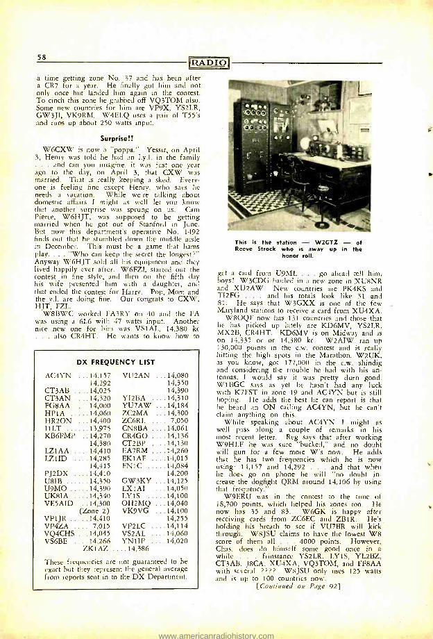
58 RADIO
a time getting zone No. 37 and has been after a CR7 for a year. He finally got him and not only once but landed him again in the contest. To cinch this zone he grabbed off VQ3TOM also. Some new countries for him are VP9X, YS2LR, GW3JI, VK9RM. W4ELQ uses a pair of T55's and runs up about 250 watts input.
Surprise!! W6CXW is now a "poppa. ' Yessir, on April
3, Henry was told he had an 1.y.l. in the family . . . and can you imagine, it was just one year ago to the day, on April 3, that CXW was married. That is really keeping a sked. Every- one is feeling fine except Henry, who says he needs a vacation. While we're talking about domestic affairs I might as well let you know that another surprise was sprung on us. Cam Pierce, W6HJT, was supposed to be getting married when he got out of Stanford in June. But now this department's operative No. 1492 finds out that he stumbled down the middle aisle in December. This must be a game that hams play.... "Who can keep the secret the longest ?" Anyway W6HJT sold all his equipment and they lived happily ever after. W6FZL started out the contest in fine style, and then on the fifth day his wife presented him with a daughter, and that ended the contest for Harry. Pop, Mom and the y.l. are doing fine. Our congrats to CXW, HJT, FZL.
W8BWC worked FA3RY on 40 and the FA was using a 6L6 with 47 watts input. Another nice new one for him was VS1AL, 14,380 kc . . . also CR4HT. He wants to know how to
DX FREQUENCY LIST
AC4YN ...14,157 VU2AN ...14,080 14,292 14,350
CT3AB ....14,025 14,390 CT3AN ....14,320 YI2BA ....14,310 FG8AA ....14,000 YU7AW ...14,184 HP1A 14,060 ZC2MA ...14,300 HR2ON 14,400 ZC6RL .... 7,050 IiLT 13,975 CN8BA ....14,061 KB6PMP 14,270 CR4GO ....14,136
14,380 CT2BP ....14,130 LZ1AA 14,410 EA7RM ....14,260 LZ1ID 14,285 EK1AF ....14,015
14,415 FN1C 14,084 PJ2DX ....14,410 14,200 U8IB 14,350 GW3KY ...14,125 U9MO 14,390 LX1AI ....14,050 UK8IA 14,340 LY1S 14,100 VESAID ...14,300 OH2MQ 14,040
(Zone 2) VK9VG 14,100 VP1JR 14,410 14,255 VP4ZA 7,015 VP2LC ....14,114 VQ4CHS 14,045 VS2AL ....14,060 VS6BE 14,266 YNIIP ....14,020
ZK1AZ ....14,386
These frequencies are not guaranteed to be exact but they represent the general average from reports sent in to the DX Department.
This is the station - W2GTZ - of Reeve Strock who is away up in the
honor roll.
get a card from U9ML . . . go ahead tell him, boys! W3CDG hauled in a new zone in XU8NR and XU2AW. New countries are PK4KS and TI2FG . . . and his totals look like 31 and 81. He says that W3GXX is one of the few Maryland stations to receive a card from XU4XA.
W8OQF now has 131 countries and those that he has picked up lately are KD6MV, YS2LR, MX2B, CR4HT. KD6MV is on Midway and is on 14,335 or or 14,380 kc. W2AIW ran up 130,000 points in the c.w. contest and is really hitting the high spots in the Marathon. W2UK, as you know, got 177,000 in the c.w. shindig and considering the trouble he had with his an- tennas, I would say it was pretty durn good. W1BGC says as yet he hasn't had any luck with K7FST in zone 19 and AC4YN but is still hoping. He adds the best he can report is that he heard an ON calling AC4YN, but he can't claim anything on this.
While speaking about AC4YN I might as well pass along a couple of remarks in his most recent letter. Reg says that after working W9HLF he was sure "bucked," and no doubt will gun for a few more W's now. He adds that he has two frequencies which he is now using: 14,157 and 14,292 . and that when he does go on phone he will "no doubt in- crease the dogfight QRM around 14,106 by using that frequency."
W9ERU was in the contest to the tune of 18,700 points, which helped his zones too. He now has 35 and 83. W6GK is happy after receiving cards from ZC6EC and ZB1R. He's holding his breath to see if VU7BR will kick through. W8JSU claims to have the lowest W8 score of them all . 4000 points. However, Chas. does do himself some good once in a while . frinstance YS2LR, LY1S, YL2BZ, CT3AB, J8CA, XU4XA, VQ3TOM, and FF8AA with several ? ? ?? W8JSU only uses 125 watts and is up to 100 countries now.
[Continued on Page 92]
www.americanradiohistory.com
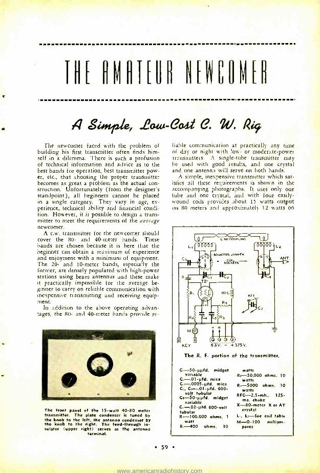
THE OMATEUR NECOMED
4 sue, .2ata-e04-1 e. W. Rif The newcomer faced with the problem of
building his first transmitter often finds him- self in a dilemma. There is such a profusion of technical information and advice as to the best bands for operation, best transmitter pow- er, etc., that choosing the proper transmitter becomes as great a problem as the actual con- struction. Unfortunately (from the designer's standpoint), all beginners cannot be placed in a single category. They vary in age, ex- perience, technical ability and financial condi- tion. However, it is possible to design a trans- mitter to meet the requirements of the average newcomer.
A c.w. transmitter for the newcomer should cover the 80- and 40 -meter bands. These hands are chosen because it is here that the beginner can obtain a maximum of experience and enjoyment with a minimum of equipment. The 20- and 10 -meter bands, especially the former, are densely populated with high -power stations using beam antennas and these make it practically impossible for the average be- ginner to carry on reliable communication with inexpensive transmitting and receiving equip- ment.
In addition to the above operating advan- tages, the 80- and 40 -meter bands provide re-
The front panel of the 15 -watt 40 -80 meter transmitter. The plate condenser is tuned by the knob to the left, the antenna condenser by the knob to the right. The feed -through in- sulator (upper right) serves as the antenna
terminal.
liable communication at practically any time of day or night with low- or moderate -power transmitters. A single -tube transmitter may be used with good results, and one crystal and one antenna will serve on both bands.
A simple, inexpensive transmitter which sat- isfies all these requirements is shown in the accompanying photographs. It uses only one tube and one crystal, and with four easily - wound coils provides about 15 watts output on 80 meters and approximately 12 watts on
LINK CCOUPLING
I 80 METER JUMPER
COI L ~ SOCKETS -~
KEY
The R. F. portion of the transmitter.
C, -50 -µpfd. midget variable
C,-.01 -ofd. mica Cs-.0005-pfd. mica C4, C5-.01- ¡ltd. 600 -
volt tubular C,- 50 -µµfd. midget variable
C7-.02 -0d. 600 -volt tubular R,- 100,000 ohms, 1
watt R4 -400 ohms, 10
watts R,- 20,000 ohms, 10
watts R1 -5000 ohms, 10
watts RFC- 2.5 -mh., 125-
ma. choke X -80 -meter X or AT
crystal L., L_ -See coil table M -O -100 milliam-
peres
59
www.americanradiohistory.com
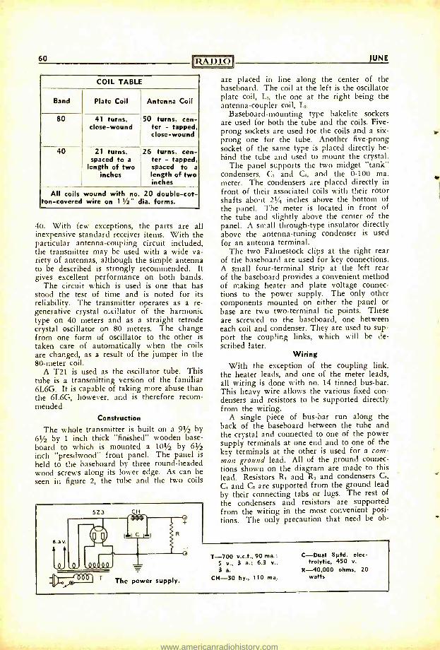
a
60 RADIO
COIL TABLE
Band
80
40
Plate Coil Antenna Coil
41 turns, close -wound
50 turns, cen- ter - tapped, close -wound
21 turns, spaced to a
length of two inches
26 turns, cen- ter - tapped, spaced to a
length of two inches
All coils wound with no. 20 double -cot- ton- covered wire on 11/2" dia. forms.
40. With few exceptions, the parts are all inexpensive standard receiver items. With the particular antenna -coupling circuit included, the transmitter may be used with a wide va- riety of antennas, although the simple antenna to be described is strongly recommended. It gives excellent performance on both bands.
The circuit which is used is one that has stood the test of time and is noted for its reliability. The transmitter operates as a re- generative crystal oscillator of the harmonic type on 40 meters and as a straight tetrode crystal oscillator on 80 meters. The change from one form of oscillator to the other is taken care of automatically when the coils are changed, as a result of the jumper in the 80 -meter coil.
A T21 is used as the oscillator tube. This tube is a transmitting version of the familiar 6L6G. It is capable of taking more abuse than the 6L6G, however, and is therefore recom- mended.
Construction
The whole transmitter is built on a 91/2 by 61/2 by 1 inch thick "finished" wooden base- board to which is mounted a 101/2 by 61/2
inch "presdwood" front panel. The panel is held to the baseboard by three round -headed wood screws along its lower edge. As can be seen in figure 2, the tube and the two coils
63V
5Z3 CH
The power supply.
JUNE
are placed in line along the center of the baseboard. The coil at the left is the oscillator plate coil, L1, the one at the right being the antenna -coupler coil, L,.
Baseboard - mounting type bakelite sockets are used for both the tube and the coils. Five - prong sockets are used for the coils and a six - prong one for the tube. Another five -prong socket of the same type is placed directly be- hind the tube and used to mount the crystal.
The panel supports the two midget "tank" condensers, C. and C6, and the 0 -100 ma. meter. The condensers are placed directly in front of their associated coils with their rotor shafts about 21/4 inches above the bottom of the panel. The meter is located in front of the tube and slightly above the center of the panel. A small through -type insulator directly above the antenna -tuning condenser is used for an antenna terminal.
The two Fahnestock clips at the right rear of the baseboard are used for key connections. A small four -terminal strip at the left rear of the baseboard provides a convenient method of making heater and plate voltage connec- tions to the power supply. The only other components mounted on either the panel or base are two two -terminal tie points. These are screwed to the baseboard, one between each coil and condenser. They are used to sup- port the coupling links, which will be de- scribed later.
Wiring With the exception of the coupling link,
the heater leads, and one of the meter leads, all wiring is done with no. 14 tinned bus -bar. This heavy wire allows the various fixed con- densers and resistors to be supported directly from the wiring.
A single piece of bus -bar run along the back of the baseboard between the tube and the crystal and connected to one of the power supply terminals at one end and to one of the key terminals at the other is used for a com- mon ground lead. All of the ground connec- tions shown on the diagram are made to this lead. Resistors R. and R. and condensers G, C, and C. are supported from the ground lead by their connecting tabs or lugs. The rest of the condensers and resistors are supported from the wiring in the most convenient posi- tions. The only precaution that need be ob-
T-700 v.c.t., 90 ma.; C-Dual 8µtd. elec-
5 v., 3 a.; 6.3 v., trolytic, 450 v.
3 a. R-40,000 ohms, 20
CH-30 hy., 110 ma. watts
www.americanradiohistory.com
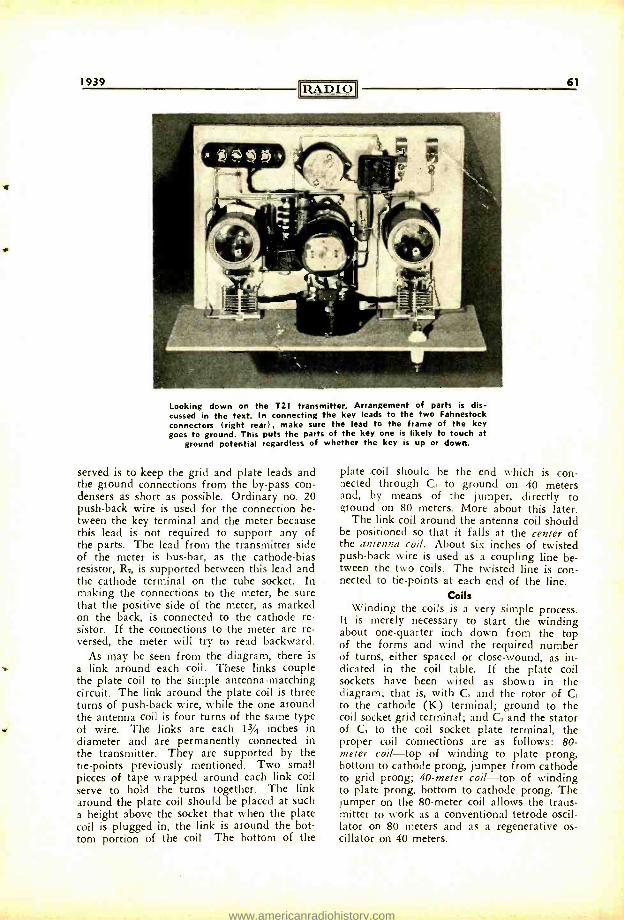
1939 RADIO 61
Looking down on the T21 transmitter. Arrangement of parts is dis- cussed in the text. In connecting the key leads to the two Fahnestock connectors (right rear), make sure the lead to the frame of the key goes to ground. This puts the parts of the key one is likely to touch at
ground potential regardless of whether the key is up or down.
served is to keep the grid and plate leads and the ground connections from the by -pass con- densers as short as possible. Ordinary no. 20 push -back wire is used for the connection be- tween the key terminal and the meter because this lead is not required to support any of the parts. The lead from the transmitter side of the meter is bus -bar, as the cathode -bias resistor, R2, is supported between this lead and the cathode terminal on the tube socket. In making the connections to the meter, be sure that the positive side of the meter, as marked on the back, is connected to the cathode re- sistor. If the connections to the meter are re- versed, the meter will try to read backward.
As may be seen from the diagram, there is a link around each coil. These links couple the plate coil to the simple antenna- matching circuit. The link around the plate coil is three turns of push -back wire, while the one around the antenna coil is four turns of the same type of wire. The links are each 13/4 inches in diameter and are permanently connected in the transmitter. They are supported by the tie -points previously mentioned. Two small pieces of tape wrapped around each link coil serve to hold the turns together. The link around the plate coil should be placed at such a height above the socket that when the plate coil is plugged in, the link is around the bot- tom portion of the coil. The bottom of the
plate coil should be the end which is con- nected through C:, to ground on 40 meters and, by means of the jumper, directly to ground on 80 meters. More about this later.
The link coil around the antenna coil should be positioned so that it falls at the center of the antenna coil. About six inches of twisted push -back wire is used as a coupling line be- tween the two coils. The twisted line is con- nected to tie -points at each end of the line.
Coils Winding the coils is a very simple process.
It is merely necessary to start the winding about one -quarter inch down from the top of the forms and wind the required number of turns, either spaced or close- wound, as in- dicated in the coil table. If the plate coil sockets have been wired as shown in the diagram; that is, with C, and the rotor of C, to the cathode (K) terminal; ground to the coil socket grid terminal; and C2 and the stator of C2 to the coil socket plate terminal, the proper coil connections are as follows: 80- meter coil -top of winding to plate prong, bottom to cathode prong, jumper from cathode to grid prong; 40 -meter coil -top of winding to plate prong, bottom to cathode prong. The jumper on the 80 -meter coil allows the trans- mitter to work as a conventional tetrode oscil- lator on 80 meters and as a regenerative os- cillator on 40 meters.
www.americanradiohistory.com
62 [RADIO
The antenna -coil connections are the same for both bands. If the socket connections are made as shown in the diagram, the two ends of the coils are connected to the cathode and plate prongs and the center tap to the grid prong.
The leads to the key may be any reason- able length (up to 10 feet, if necessary). A 0.02 -pfd. condenser, C7, is connected directely across the key. This condenser is used to mini- mize key clicks and is most effective when placed right at the key rather than in the transmitter.
Power Supply
The power supply used with the transmitter is a standard brute -force filtered affair using receiver components throughout. A 40,000 - ohm bleeder resistor, R, is used across the out- put to stabilize the voltage under keying and discharge the filter immediately when the transmitter is shut off. The parts are mounted on a small baseboard in the most convenient manner and the heater and plate voltage con- nections brought out to a four -post terminal strip similar to that on the transmitter. The power transformer should not deliver more than 350 v. r.m.s. each side of c.t. or else the peak voltage on the filter condensers will be too high when the key is up.
Antenna
The best type of antenna for use with this transmitter is the end -fed half -wave 80 -meter type. Such an antenna, if erected reasonably in the clear, will give good results on both 80 and 40 meters. On both bands the antenna is not particularly directional, although a slight increase in signal strength will be no- ticed in certain directions. On 40 meters the antenna produces low -angle radiation, an ad- vantage in working dx.
The antenna should measure 135 feet from the far end to the antenna terminal on the transmitter and be erected in the clear and as high and as much in a straight line as possi- ble. Although it is not to be recommended, it is possible to zig -zag the "flat -top" portion back and forth to make up the necessary length if the space available for the antenna is limited. The section of the antenna from the flat top to the transmitter should be kept as far away from houses and trees and large metal objects as practical. A good -quality lead - in bushing must be used where the antenna enters the operating room, as the portion of the antenna near the transmitter is at high r.f. voltage in this system. Three -inch receiv- ing -type insulators of good quality glass can be used to support the antenna.
Tuning Up
If all the wiring has been done properly, no difficulty should be experienced in placing the transmitter into operation. Leads to the power supply and key should be connected (ordinary lamp cord of good quality will do) and a 6.3 -v. 150 -ma. dial light placed in series with the antenna at the transmitter. A crystal with a frequency between 3502 and 3648 kc. should be placed in the crystal socket. A crys- tal in this range will allow operation on both the 80- and 40 -meter bands.
80 -Meter Tuning Procedure
Place 80 -meter coils correctly in the plate and antenna sockets and close the switch on the power supply, permitting the T21 cathode to warm up. After a period of a half minute or so, close the key.
The antenna condenser should be set at minimum capacity and the plate condenser at maximum. Start tuning the plate condenser toward minimum capacity, watching the cath- ode meter. As the condenser is tuned, there will be no change in current until the circuit is tuned to the crystal frequency. At this point the current will take a sudden drop, indicating that the crystal is oscillating. Tune the con- denser slightly toward minimum capacity from the point where the crystal started oscillating. The plate condenser should now be left at this setting and attention transferred to the antenna -tuning condenser.
Keeping one eye on the plate meter and one on the dial light in series with the antenna, start tuning the antenna condenser toward maximum capacity. As the capacity of this condenser is increased, the plate current should gradually increase and the dial light start to glow. Adjust the antenna -tuning condenser for maximum brilliance of the light. If the cathode current should take a sudden jump and the dial light go out, it is an indication that the oscillator has been pulled out of oscillation and the plate condenser should be turned further toward minimum capacity until the plate current again makes a sudden jump upward or downward, indicating that oscilla- tion has begun again. If it is impossible to restore oscillation after the antenna circuit is tuned, the link coupling between the plate and antenna coils must be loosened. This is done by pushing the link around the plate coil down farther away from the coil. The link around the antenna coil should never be touched; it should always be around the cen- ter of the antenna coil.
When the transmitter is properly adjusted it should be possible to tune the antenna
[Continued on Page 88]
www.americanradiohistory.com
B y E. H. C O N K L I N , * W 9 B N X
28 Mc. We have been interested in the many cases
of short skip on ten meters during the past winter, and the "woof- woof" fading of some of these signals. The ionosphere storm of Feb. 24, mentioned last month, was accom- panied by sporadic -E -layer reflections which would account for the skip that night. The turbulent nature of the ionosphere explains the peculiar audio- frequency fading.
The National Bureau of Standards states that the more common, poor, short -path ten - meter transmissions appear to be by scattered reflections which have been discussed in several ionosphere papers. These reflections are occasionally called G -layer reflections. They are common on somewhat lower fre- quencies when the ionization density is too low for regular E- or 'F -layer transmissions. They are usually much weaker than refractive F -layer transmissions and of very poor quality due to the rapid fading. They ex- hibit no sharp cutoff with variation of fre- quency or distance. Probably some of the 56 -Mc. transmission is produced in the same way. An experienced operator can distinguish this type of transmission from regular F -layer or good sporadic -E transmission. The trans- missions are probably caused by weak reflec- tions from the E and F layers after the regu- lar maximum usable frequencies have been exceeded.
The fluttering modulation observed on such transmissions (via scattered reflections on G layer) appears to be caused by interference of waves over different paths and rapid changes in path length which produce the rapid fading. There is a change of phase at the receiver with a change of path length; this is complicated by interference of rapidly fading signals over several paths.
* ex -W9FM, Associate Editor, RADIO, Wheaton, 111.
56 Mc. We are indebted to the National Bureau of
Standards for the above explanation of flutter- ing 28 -Mc. near -dx signals, and for comments on the 56 -Mc. dx during the Feb. 24 and other ionosphere storms. The general mushiness of signals heard was caused by the turbulence or boiling of the ionosphere. During such a severe storm, the auroral zone has spread as far south as Washington. The regular layers of the ionosphere are torn up. There are numerous patches or clouds of ionization but they do not remain fixed in height or ioniza- tion density.
We find regular comments on transmission conditions, the ionosphere, magnetic storms and sunspots in British magazines such as the Short Wave Magazine edited by G6FO. There seems to be much less interest in these subjects in this country, or else the interest is dormant. The question is, do our readers want such comments, or don't they? Sooner or later we all may take a greater interest in conditions and in predicting them.
May Field Days
If you did not read the announcement of the May field days last month, you will still be able to get in on them. The object is to stress 56 -Mc. dx attempts at distances of 100 to 300 miles, on Saturdays and Sundays in May. Special efforts should be concentrated on the periods from 9:00 a.m. to noon, and 5:00 to 8:00 p.m. central time.
Improved C.W. Needed
Don Dayton, W8VO, says that there have been many days in the past winter when he could have logged and possibly worked W2's from Ohio but for one thing -mainly the in- stability of c.w. signals at low audibility levels. Also, there is not enough c.w. used to sign off or call. Keying with heavily loaded exciter stages causes a slight shift in note, of one to ten kilocycles not counting the drift of as high as 40 kc., when using a very high - frequency crystal. This makes numerous sig- nals impossible to read when just audible on a clear background. Better stability will in- crease the number of "open" days when c.w. will get through although the band may be closed for phone. Stability in the receiver needs attention, especially in the h.f. oscil- lator circuit where some shift will occur with line voltage changes, and drift with time.
Miscellany In Gloversville, N. Y., W8ITN is on five
meters using a 40 -meter antenna. W8FPC in Johnstown, N. Y., is using a 160 -meter an- tenna. These stations may break the trans - New York gap when they start to "click"
ei
www.americanradiohistory.com
64 RADIO
on the dx. W8EID and W2KLZ are on the air almost every night.
In Allentown, Pa., W3B1'F says that things are picking up with a new station heard nearly every week. W2MO is worked about three times a week. On March 28 at 10:45 p.m., he heard the c.w. signals of W8CIR QSA5 R7 with a funny watery waver which was characteristic of all signals that evening. The W8CIR reception did not seem to be the usual low atmosphere bend- ing, such as when WI's are heard, because the beam did not make any difference.
W8QDU has finished the dx contest and has returned to "five" in earnest. His mobile set is operating on both five and ten meters. He is using a signal shifter at the home location, so may be found anywhere in the band with his kilowatt, using a pair of 250TH's. His rebuilt receiver uses a three - stage acorn preselector. He is putting up a new multi-element rotary beam.
From Shamokin, Penn., W8OKC writes to say that he has had such improved results from a system of ground radials under his 20 -meter vertical that he is going to try the same thing under a three- or four -section vertical rotary W8JK for five meters.
We note that the new RME converter uses a 6SJ7 mixer tube and 6J5 oscillator -some- what comparable to using a 57 mixer. The sharp cutoff pentodes, including the 57, 6C6, 6J7, 1852 and 954 have not yet lost out for this position. RME hooks the suppressor of the mixer tube directly to the control grid of the oscillator.
W8VO has a preselector using two acorns and three tuned circuits; his receiver has acorn r.f. and detector stages, 6J5 oscillator, 4 -Mc. i.f. The preselector is put in front of the receiver only when the background noise is low; it is designed for signal -to -noise ratio rather than for maximum gain, and works very well when atmospheric noises are down. He does not believe that it helps the receiver when there is auto ignition or other electrical disturbances.
Up in Portland, W7AVO say that activity is getting under way. He is running daily transmissions to the east at 12:30 and 5:30 p.m. Pacific time. These local stations were in actual operation at the end of March:
W7ABZ -30 watts, vertical antenna W7AQJ -10 watts, Sterba curtain W7AVO -60 watts, 3- element beam W7FDJ -150 watts, vertical beam W7FFE -105 watts, beam antenna W7EGV -150 watts, beam antenna
Al Friend, W8DSJ, says that West Virginia University in Morgantown has a mobile
JUNE
u.h.f. unit rigged up and may join in a
relay from the top of some mountain. The unit was built as a telephone circuit for con- trolling their reflection field tests. The transmitter has 35 watts on the final 6L6. On a fairly high spot ten miles northeast of Morgantown, W8DSJ can hear the Wheeling, W. Va., police R9 plus, and amateur har- monics. Soon he will have 250 watts into a six -element beam, at the university. That will make a nice contact for WBVO, W8CIR, W3GLV, and others.
W1LIG says that W2KTF arranged trans- atlantic tests with GM6RG but no reports have come in yet. With the sunspot cycle on the way .down, the only possibility of transatlantic work now seems to be chance three -hop summer work via sporadic -E -layer such as the W1 -W6 dx last year.
Of all the things that we have written, the one bringing the greatest number of inquiries and comments is "Transmission Lines as Cir- cuit Elements." The way was paved some- what by earlier articles on concentric line tuned circuits in u.h.f. receivers. We hope that the receiver description in this issue will clear up some of the remaining points about the practical application of such lines to transmitters and receivers.
In Texas, W5DOB of Hamlin and W5BYV of McCamey are running daily tests over a distance of 200 miles and are having fair success. W5DOB is on 56,408 kc. at 1:00 to 1:30 p.m. central time daily with 150 watts, tone modulated, using a Yagi beam pointed west. W5EIN of Big Lake has about 150 watts also. W5FNQ of Texon is now on the band. W5ANU of Midland is getting ready. It looks like there will be a lot of W5's on 56 Mc. for the W9 -W8 -W6 districts to work this summer, and a better chance for two -hop work with Wl -W2.
W1HXE again sent us copies of the M.V.A.R.C. News. We learn that W1LKG is operating portable at Phillips Exeter Academy. W1IYT is putting a good signal into New Hampshire. W1JOG in New Hampshire is back with a battery- operated rig. W1KTV of Newington, N. H., is on with a 100 -watt transmitter. W1KXK on 57.4 Mc. has a new superhet with two r.f. stages and all the trimmings. W1LGG is polishing up his set. W1COX says that he worked a W9 in the late winter but we have no details at all.
Chicago's "Ultra High Frequency Club" has taken into hand the problems of work- ing some 50 -200 mile dx with a degree of consistency. W9SQE requests information as to what stations in Michigan, Indiana, Wis- consin and Illinois within 150 miles or so of
www.americanradiohistory.com
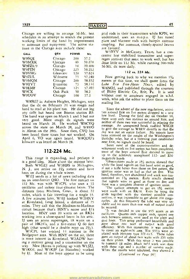
1939 RADIO
Chicago are willing to arrange 56 -Mc. test schedules in an attempt to stretch the present working limits of the band by improvement in antennas and equipment. The active sta- tions in the Chicago area include these:
CALL QTH POWER Mc.
W9SQE Chicago 200 57.2 W9MXK Chicago 40 59.270 W9FZS/9 Chicago 10 59.400 W9FEN Chicago 225 56.212 W9VHG Glenview 120 57.624 W9ZUL Wilmette 75 57.240 W9MQM Chicago 200 58.352 W9TVT Evanston 75 58.144 W9EMF Chicago 125 57.492 W9CX Oak Park 50 58.2 W9UOV Chicago 100 57.2
W8SLU in Auburn Heights, Michigan, says that the dx on February 24 was rough and hard to read at his place too. He did not log any calls but heard one Boston station R9. The band was open on March 1 and 3 but not very good. More rough dx signals were heard on March 28. He worked W8CVQ across the state on March 28, and W8VO in Akron on the 28th. Since then, CVQ has been heard three times but not worked. On April 6, VO was again heard. W8QDU's kilowatt was heard on March 28.
112 -224 Mc. This range is expanding, and perhaps it
is a good idea. More about the reasons later. Both W3GZJ and W3HBS in Millington,
N. J., are active on 21/2 meters and have been on during the whole winter.
W1IJ sends in a lot of news including data on an interdistrict QSO. The first contact on 112 Mc. was with W1CPL who uses a 53 oscillator and indoor four -element beam. The distance from Madison, Conn., is about 22 miles, which is fair traveling for a single 53. A few minutes later, W1IJ hooked 'X'2HNY
s. at Riverhead, Long Island, a distance of 25 miles. They call this the Madison -to- Madison circuit because that's HNY's name and Il's location. HNY uses 20 watts on an RK34 working into a close- spaced beam in his attic. IJ uses an acorn superregen, 18 watts on a pair of HK24's, and a five -meter Q 60 feet high (that would be a double zepp on 21/2).
W1CPL has worked 14 stations in the Bridgeport area. With HNY on the air, there is more interest in Riverhead, W2ADW hav- ing a receiver going and a transmitter on the way. New Haven is picking up with W1JZJ, W1KGL and W1KJF (at Hamden) worked by IJ. Most of the boys appear to be using
65
grid rods in their transmitters while KPN, we understand, uses an m.o.p.a. IJ has tuned plate and filament rods with hairpin antenna coupling. For antennas, closely -spaced beams are favored.
W5BYV in McCamey, Texas, has a con- centric line stabilized transmitter and super - regen receiver that seem to work well, but has done little on 112 Mc. while running 200 -mile 56 -Mc. dx tests daily.
112 vs. 224 Mc.
Now getting back to why we mention 11/4 meters at this time, we shall quote from the Lake Erie Five -Meter News, edited by W8NOJ, and published through the courtesy of Bliley Electric Co., Erie, Pa. It is sent without cost to amateurs engaged in u.h.f. work, who ask the editor to place them on the mailing list.
'Since the advent of the new regulations, activi- ties around Erie on five meters dropped to a new low level. During the field day on October 16, there were only two stations on around Erie, and neither of these two was successful in relaying the message. An unexpected break enabled W8CIR to give the message to W8RV directly so that the day was not an entire failure. No reports have been received on the results of the Washington's Birthday relay, but at a listening post established near Erie, no signals could be heard.
"Since most of the experimentation and de- velopment work on five meters has been completed, some of the boys around Erie decided to move up to the relatively unexplored 112- and 224 - megacycle bands
"Observations made at 21/2 meters showed that while the local signals on this band were as good, if not a trifle better than those on five meters, the ignition noise was as bad as that on five. This band, therefore, was abandoned and work was con- centrated on 11/4 meters. Early results showed that signals were as good as those on five and there was a complete absence of ignition noise.
"The earliest attempts to get on 11/4 meters were made with an RK34. Even by tying the grids together with the shortest possible con- nection, it was impossible to get above 200 mega- cycles. At this frequency the tube was very un- stable and no more than one watt of output could be secured.
"It was decided to use the 955 acorn as an oscillator. Quarter -inch copper rods, spaced one inch between centers, were used as the plate and grid lines. This setup performed beautifully and gave about one watt of output with good efficiency. With this transmitter it was possible to cover an eight -mile area. The 955's were re- placed with Hytrons type HY -615. These tubes gave an output of about two watts with 250 volts on their plates. With this setup it was possible to transmit 18 miles. Much field work was done with these rigs and a number of surveys made. When the results were tabulated, they showed a
[Continued on Page 90)
www.americanradiohistory.com
En Root S.F. World's Fare Deer Hon Ed.:
Scratchi are get chance to inspeck grate S.F. World's Fare and Ranch on Pleasure Eyeland all free of charge on account of win local newspaper confect for subscription cam - pain. Scratchi are went immediately, on ac- count of I are figgure had better take advan- tage of this lovable opportunity before news- paper get wise to how Scratchi are get so many peoples to sine up for their rag.
Hee hee haw haw Hon. Ed., you see I are telling people I are getting signatures for patition which are calling for bill in State legislature which are a "Mature Age Pension Fund," which are call for give everybodies in Calif. over 21 years old $100 every Saturday. Peoples are in such a big hurry to sine the patition they do not even bother to read what are putting autograph on, which are an agree- ment to take paper for three months.
So Scratchi are riding to the S. F. Fare on steam line train for big time at no cost. To- night while Scratchi are almost get hisself tied up in knots trying to get self inserted into pujiyammas while curled up inside pullmen berth, a grate idear on how to make monies are born. You see, Scratchi are figgure that will not be good idear to go back and face eyerate newspaper gentlefellows, and maybe are wise to settle in some new town.
What are having in mind hon. ed. are that maybe you would like to make partners in this wonderful venchoor, in which case I
would settle in Lost Angeles and build factory there. You would furnish the monies for the factory and Scratchi would furnish the brains, which are only fair on account of Scratchi are have so much more brains than monies that have no monies at all, and therefore couldn't invest monies anyhow.
New idear are for manufacture line of men's toylet articles, and means of advertise same which would result in so many orders that could not filling them all. Are figure on call it the Scratchi S.S.S. Co. and prodoose Scratchi Stickunt Shellac, "The Hare Dressing Soupreatn "; Scratchi Shaving Salve, "The
Soothing Shaving Lotion "; Scratchi Savory Sope, "The Sope with the Pretty Stink "; Scratchi Souper Shine, "The Teeth Powder what Give a Satin Finish "; and Scratchi Slosh- ing Solution, "The Deodorant Mouth Bath."
What are grate advertising skeem to result in collosus sails of Scratchi S.S.S. producks? It are a wonderful advertising method and besides are not costing much of anything. Scratchi are going to put hisself on the air with a stewpendous Calif. kilowatt on 20, 75, and 160 meters phone and be on the air prac- tically all of the time. Of coarse it are against the rules of the FCC to use amchoor trans- mitters for advertising or otherwise for fatten- ing own bank roll, either directly or by back door.
But Scratchi are a pretty sly fellow all right. How can FCC do anything if Scratchi are in- nocently say, "Please QRX a minute while I
are go relieve my soar throat with some of that peechy Scratchi Sloshing Solution what are always do the business ?" Or if Scratchi drop a casual remark such as: "I'm sorry I
missed part of your last transmission old man but the Scratchi Savory Sope with which I are bathe my hands have such a pretty smell that it are hard for me to keep my mind on the QSO." I ask you hon. ed. what charge could they hang on Scratchi for saying for instants: "Boy do your signal stand out from the others, just like teeths what have been cleaned with Scratchi Souper Shine, that f.b. teeth powder."
I think by now you are get the idear hon. ed., and are trust you to keep it secrut between self and gait post. Please reply by return male and let me know if you want to go into 50 -50 partnership and put up the monies for factory and high power phone transmitter, as the matter of monies are the weakest chain in the link.
Very truly yours, HASHAFISTI SCRATCHI
Gqß/2444n
40 M. Fone and Foreign Hogwash
Los Angeles, Calif. Sirs:
A couple of years ago the League strongly urged that the amateurs on the 7 -Mc. band spread out and occupy the high- frequency por- tion of the band. But they didn't take heed: occupancy continued to be much more sparse than in the rest of the band. So at Cairo the
[Continued on Page 86]
66
www.americanradiohistory.com
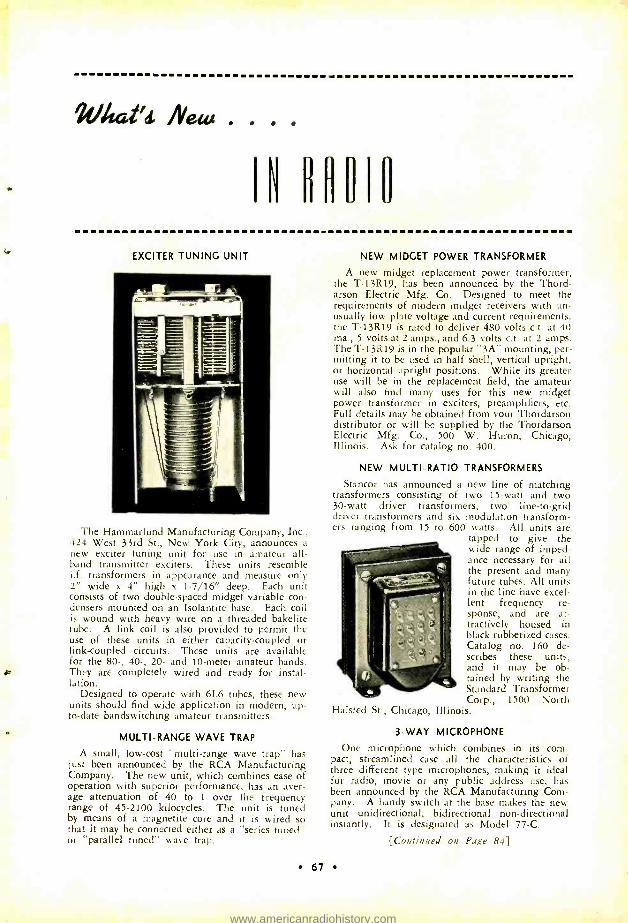
2atai'd /Veia
IN flHflIU
EXCITER TUNING UNIT
The Hanunarlund Manufacturing Company, Inc., 424 West 33rd St., New York City, announces a new exciter tuning unit for use in amateur all - band transmitter exciters. These units resemble i.f. transformers in appearance and measure only 2" wide x 4" high x 1- 7/16" deep. Each unit consists of two double -spaced midget variable con- densers mounted on an Isolantite base. Each coil is wound with heavy wire on a threaded bakelite tube. A link coil is also provided to permit the use of these units in either capacity -coupled or link -coupled circuits. These units are available for the 80 -, 40 -, 20- and 10 -meter amateur bands. They are completely wired and ready for instal- lation.
Designed to operate with 6L6 tubes, these new units should find wide application in modern, up- to -date bandswitching amateur transmitters.
MULTI -RANGE WAVE TRAP
A small, low -cost "multi -range wave trap" has just been announced by the RCA Manufacturing Company. The new unit, which combines ease of operation with superior performance, has an aver- age attenuation of 40 to 1 over the frequency range of 45 -2100 kilocycles. The unit is tuned by means of a magnetite core and it is wired so that it may be connected either as a "series tuned" or "parallel tuned" wave trap.
NEW MIDGET POWER TRANSFORMER
A new midget replacement power transformer, the T- 13R19, has been announced by the Thord- arson Electric Mfg. Co. Designed to meet the requirements of modern midget receivers with un- usually low plate voltage and current requirements, the T -13R19 is rated to deliver 480 volts c.t, at 40 ma., 5 volts at 2 amps., and 6.3 volts c.t. at 2 amps. The T -13R19 is in the popular "3A" mounting, per- mitting it to be used in half shell, vertical upright, or horizontal upright positions. While its greater use will be in the replacement field, the amateur will also find many uses for this new midget power transformer in exciters, preamplifiers, etc. Full details may be obtained from your Thordarson distributor or will be supplied by the Thordarson Electric Mfg. Co., 500 W. Huron, Chicago, Illinois. Ask for catalog no. 400.
NEW MULTI -RATIO TRANSFORMERS
Stancor has announced a new line of matching transformers consisting of two 15 -watt and two 30 -watt driver transformers, two line -to -grid driver transformers and six modulation transform- ers ranging from 15 to 600 watts. All units are
tapped to give the wide range of imped- ance necessary for all the present and many future tubes. All units in the line have excel- lent frequency re- sponse, and are at- tractively housed in black rubberized cases. Catalog no. 160 de- scribes these units, and it may be ob- tained by writing the Standard Transformer Corp., 1500 North
Halsted St., Chicago, Illinois.
3 -WAY MICROPHONE
One microphone which combines in its com- pact, streamlined case all the characteristics of three different type microphones, making it ideal for radio, movie or any public address use, has been announced by the RCA Manufacturing Com- pany. A handy switch at the base makes the new unit unidirectional, bidirectional non -directional instantly. It is designated as Model 77 -C.
[Continued on Page 84]
67
www.americanradiohistory.com
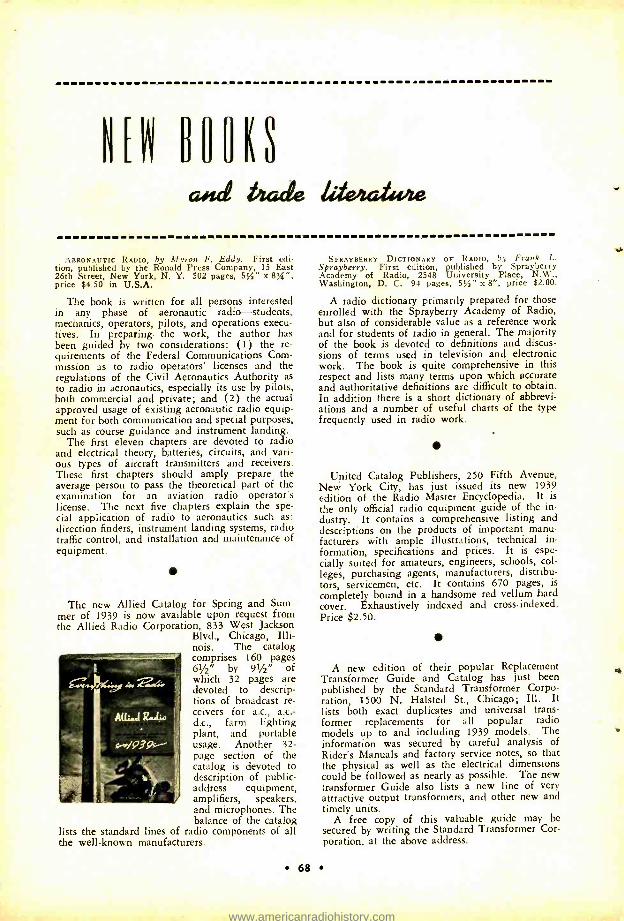
M UHUKS
and butt& kle24444e
AERONAUTIC RADIO, by Myran F. Eddy. First edi- tion, published by the Ronald Press Company, 15 East 26th Street, New York, N. Y. 502 pages, 5%" x 8 % ", price $4.50 in U.S.A.
The book is written for all persons interested in any phase of aeronautic radio -students, mechanics, operators, pilots, and operations execu- tives. In preparing. the work, the author has been guided by two considerations: (1) the re- quirements of the Federal Communications Com- mission as to radio operators' licenses and the regulations of the Civil Aeronautics Authority as to radio in aeronautics, especially its use by pilots, both commercial and private; and (2) the actual approved usage of existing aeronautic radio equip- ment for both communication and special purposes, such as course guidance and instrument landing.
The first eleven chapters are devoted to radio and electrical theory, batteries, circuits, and vari- ous types of aircraft transmitters and receivers. These first chapters should amply prepare the average person to pass the theoretical part of the examination for an aviation radio operator's license. The next five chapters explain the spe- cial application of radio to aeronautics such as: direction finders, instrument landing systems, radio traffic control, and installation and maintenance of equipment.
The new Allied Catalog for Spring and Sum- mer of 1939 is now available upon request from the Allied Radio Corporation, 833 West Jackson
Blvd., Chicago, Illi- nois. The catalog comprises 160 pages 61/2" by 91/2" of which 32 pages are devoted to descrip- tions of broadcast re- ceivers for a.c., a.c.- d.c., farm lighting plant, and portable usage. Another 32- page section of the catalog is devoted to description of public - address equipment, amplifiers, speakers, and microphones. The balance of the catalog
lists the standard lines of radio components of all the well -known manufacturers.
68
SPRAYBERRY DICTIONARY OF RADIO, by Frank L. Sprayberry. First edition, published by Sprayberry Academy of Radio, 2548 University Place, N.W., Washington, D. C. 94 pages, 514" x 8 ", price $2.00.
A radio dictionary primarily prepared for those enrolled with the Sprayberry Academy of Radio, but also of considerable value as a reference work and for students of radio in general. The majority of the book is devoted to definitions and discus- sions of terms used in television and electronic work. The book is quite comprehensive in this respect and lists many terms upon which accurate and authoritative definitions are difficult to obtain. In addition there is a short dictionary of abbrevi- ations and a number of useful charts of the type frequently used in radio work.
United Catalog Publishers, 250 Fifth Avenue, New York City, has just issued its new 1939 edition of the Radio Master Encyclopedia. It is the only official radio equipment guide of the in- dustry. It contains a comprehensive listing and descriptions on the products of important manu- facturers with ample illustrations, technical in- formation, specifications and prices. It is espe- cially suited for amateurs, engineers, schools, col- leges, purchasing agents, manufacturers, distribu- tors, servicemen, etc. It contains 670 pages, is completely bound in a handsome red vellum hard cover. Exhaustively indexed and cross -indexed. Price $2.50.
A new edition of their popular Replacement Transformer Guide and Catalog has just been published by the Standard Transformer Corpo- ration, 1500 N. Halsted St., Chicago; Ill. It lists both exact duplicates and universal trans- former replacements for all popular radio models up to and including 1939 models. The information was secured by careful analysis of Rider's Manuals and factory service notes, so that the physical as well as the electrical dimensions could be followed as nearly as possible. The new transformer Guide also lists a new line of very attractive output transformers, and other new and timely units.
A free copy of this valuable guide may be secured by writing the Standard Transformer Cor- poration, at the above address.
www.americanradiohistory.com
We Stacked 'Em Up To The Ceiling . . . . .
When the new, 1939 "RADIO" HAND- BOOK was published last fall, we stacked thousands of copies up to the very ceiling of our shipping room. But the supply didn't begin to meet the demand. Last month, we were forced to make a large re -run and stack 'em up again!
The Reason . . .
The reason is simple! The new, 1939 "RADIO" HANDBOOK with over 550 pages, profusely illustrated, is the fore- most and most authoritative text and ref- erence work on Construction . . . Equip- ment . . . Operation . . . Theory of high and ultra -high frequency radio obtainable. Get it from your local radio parts dealer, or order direct from us.
$1.50 Prepaid, In Continental U.S.A.1 $1.65 Prepaid, Elsewhere
By
The Editors of "Radio" 7460 Beverly Blvd., Los Angeles, Cal.
www.americanradiohistory.com
VflNN alih° NON1H
Y. L. TROUBLE
Patricia looked disgustedly at the ancient double- button mike before her. It hung by a piece of door spring and fish line from the ceiling. Its scarred and slightly corroded face stared coldly at her, ready to carry her soft CQ out over the ether.
"But what's the matter with that mike ?" asked Ken indignantly.
"Well, Ken, it hasn't any appeal," she said with a sigh. "Now take Art's for instance.
. It's just like they use in the movies and.. "
"Art's this, and Art's that," exploded Ken waving his arms wildly. "That's all I hear now. If I hadn't introduced you to him you wouldn't have seen his rig . . . sprayed all over with doo -dads and what -nots. Bah! I'm disgusted," he ended breathlessly.
"You're disgusted," she countered, "Humph, look at my arm ... yes, burned by that messy ol' soldering iron there. And how about my stockings? I get runs every time I walk into the shack, from wires stickin' out everywhere. And that's not all, Kenneth Stone, I'm not coming back until you have a transmitter with charm." She stamped stiffly out of the shack, banging the door violently. The one remaining hinge gave way and the door came crashing down.
Ken was stunned. Patricia had been his girl since almost before he had taken up ham radio. The rig had never offended her be- fore. It had carried her voice over many thousands of miles. There was never a CQ that didn't bring several answers. In fact, he summed up, as he stood dejectedly amongst a maze of wires, coils and cigarette butts, everything had been swell up until now.
"Charm," he muttered to himself, "why that guy Art can't even work outa his own hack yard." Ken flipped over the trans- mitter's toggle switch. "CQ, CQ, CQ," he bellowed belligerently. With a vengeance Ken swept swiftly over the 20 -meter band but it was of no avail. His thoughts were not of making a QSO; Pat was on her way
over to Art's house this very minute.... He was sure of that.
Patricia usually walked fast, but right now she was tapping out a veritable tattoo, her high heels beating a staccato on the sidewalk. She had been insulted long enough, and the farther from that pile of junk and smell of overloaded resistors she could get -the hap- pier she would be.
"My, what a hurry you're in," sang a voice from the curb.
"Why, Art, it's you," exclaimed Patricia with surprise.
"Sure, hop in and I'll take you where you're going."
"Oh, how kind of you." The flashy roadster roared away. "And
how is the little Radio Girl ?" questioned Art. "I heard you on twenty over Ken's rig last night; boy you sure can raise the stations."
"You did, huh," fidgeted Patricia. "And how! Say, suppose you try that ir-
resistible voice over at my place . . . I've got five hundred watts input," he added proudly.
Nothing could have suited her better at
this particular moment. But to be too hasty in acceptance of the invitation would show poor taste. "Yes, I think I would, but not now ... tonight perhaps," accepted Patricia. "You may call for me at seven thirty if you want."
"Swell!" exclaimed Art. "I'll take you home now and then get the rig all tuned
uP "All tuned up." She turned that over in her mind the rest of the way home. Sure funny a rig like his had to be "all tuned up," but maybe that was the way those elaborate sets were. Maybe he had been on another band.
Ken tried to be unconcerned over the after- noon's happenings, but he kept recalling the final words of Patricia. Perhaps she was right, but still the ol' rig seemed to perk right along night after night, day after day, and never any complaints of poor modulation, al-
By H O W A R D W E L L E R. W 6 I P
70
www.americanradiohistory.com
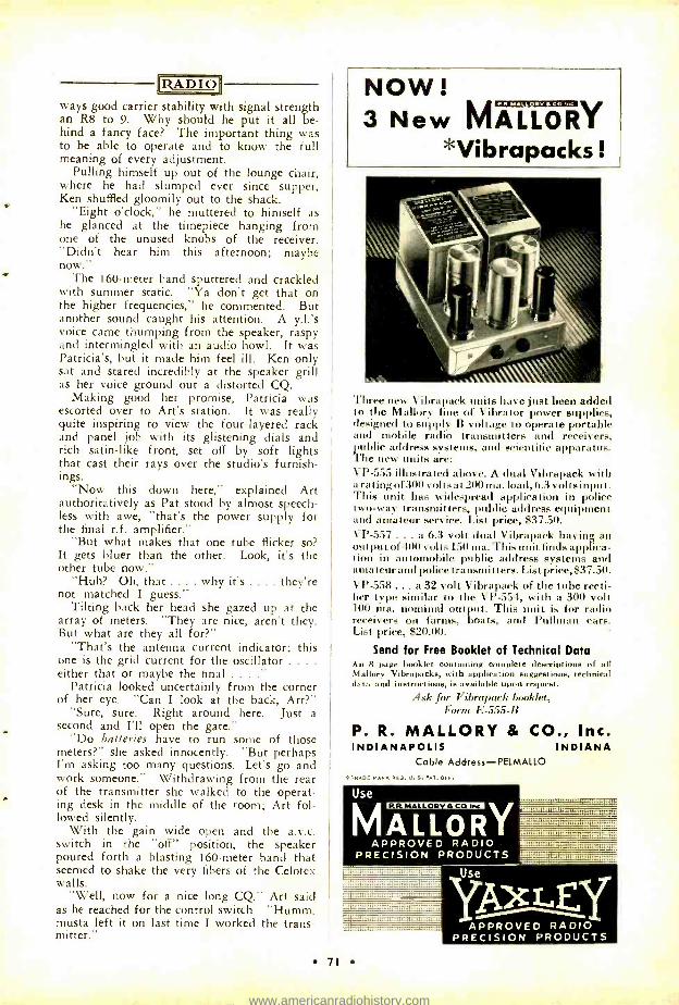
RADIO ways good carrier stability with signal strength an R8 to 9. Why should he put it all be- hind a fancy face? The important thing was to be able to operate and to know the full meaning of every adjustment.
Pulling himself up out of the lounge chair, where he had slumped ever since supper, Ken shuffled gloomily out to the shack.
"Eight o'clock," he muttered to himself as he glanced at the timepiece hanging from one of the unused knobs of the receiver. "Didn't hear him this afternoon; maybe now."
The 160 -meter band sputtered and crackled with summer static. "Ya don't get that on the higher frequencies," he commented. But another sound caught his attention. A y.l.'s voice came thumping from the speaker, raspy and intermingled with an audio howl. It was Patricia's, but it made him feel ill. Ken only sat and stared incredibly at the speaker grill as her voice ground out a distorted CQ.
Making good her promise, Patricia was escorted over to Art's station. It was really quite inspiring to view the four -layered rack and panel job with its glistening dials and rich satin -like front, set off by soft lights that cast their rays over the studio's furnish- ings.
"Now this down here," explained Art authoritatively as Pat stood by almost speech- less with awe, "that's the power supply for the final r.f. amplifier."
"But what makes that one tube flicker so? It gets bluer than the other. Look, it's the other tube now."
"Huh? Oh, that .... why it's .... they're not matched I guess."
Tilting back her head she gazed up at the array of meters. "They are nice, aren't they. But what are they all for ?"
"That's the antenna current indicator; this one is the grid current for the oscillator ... .
either that or maybe the final ...." Patricia looked uncertainly from the corner
of her eye. "Can I look at the back, Art ?" "Sure, sure. Right around here. Just a
second and I'll open the gate." "Do batteries have to run some of those
meters ?" she asked innocently. "But perhaps I'm asking too many questions. Let's go and work someone." Withdrawing from the rear of the transmitter she walked to the operat- ing desk in the middle of the room; Art fol- lowed silently.
With the gain wide open and the a.v.c. switch in the "off" position, the speaker poured forth a blasting 160 -meter band that seemed to shake the very fibers of the Celotex walls.
"Well, now for a nice long CQ," Art said as he reached for the control switch. "Humm, musta left it on last time I worked the trans- mitter."
NOW! 3 New M A ®Y
*Vibrapacks!
Three new Vibrapack units have just been added to the Mallory line of Vibrator power supplies, designed to supply B voltage to operate portable and mobile radio transmitters and receivers,
Tpublic address systems, and scientific apparatus. he new units are:
VP -555 illustrated above. A dual Vibrapack with a rating of 300 volts at 200 ma. load, 6.3 volts input. This unit has widespread application in police two -way transmitters, public address equipment and amateur service. List price, $37.50. VP-557 ... a 6.3 volt dual Vibrapack having an output of 400 volts 150 ma. This unit finds applica- tion in automobile public address systems and amateur and police transmitters. List price, $37.50. VP- 558... a 32 volt Vibrapack of the tube recti- fier type similar to the VP -554, with a 300 volt 100 ma. nominal output. This unit is for radio receivers on farms, boats, and Pullman cars. List price, $20.00.
Send for Free Booklet of Technical Data An 8 page booklet containing complete descriptions of all Mallory Vibrapacks, with application suggestions, technical data and instructions, is available upon request.
Ask for Vibrapack booklet, Form 1i- 555 -1i
P. R. MALLORY & CO., Inc. INDIANAPOLIS INDIANA
Cable Address - PELMALLO
*TRADE MARK REG. U. S. PAT. OFF.
P.R.MALLORV aCO
71
Use yAy APPROVED RADIO
PRECISION PRODUCTS
www.americanradiohistory.com
IRADIO'
The hands of the chronometer crawled to 8:15 p.m. Still there was no answer to the two CQ's he had called in the last fifteen minutes.
Patricia was uneasy. With all this equip- ment surely there was someone who heard the calls ... they were long enough anyway. There lingered in her mind for an instant those many CQ's she had called at Kenneth s. An answer was always taken for granted, and she was hardly ever disappointed.
Impatiently she sat listening as he twirled the dial. With a blurp a CQ boomed out. The dialing slowed down and retreated to the signal.
"We'll give him a call," said Art as he manipulated the controls with more than the required attention. "Here, you take it."
With her best radio manners and in her sweetest voice she called the station, al- though she knew it was only across town. It was a short call but while calling she was comparing stations. It was a swell mike, with floor stand 'n everything . . . . So different, too, from what she had been accustomed to talking into . . But still, Ken seemed to get out. By that time she was signing over, anxiously awaiting an answer.
"Well, you're QSA three R nine plus," their contact replied. "All I could get was the call letters; the signal is all mushed up. . . . It sounded like a y.l. though. Come back again and I'll check your carrier."
His face flushed crimson, Art bellowed a return, as if to cover his embarrassment. Patricia drummed the desk top with nervous fingers.
Sympathetically, Ken had stayed by his re- ceiver, listening intently to the nerve jarring signals from Art's rig. It was now ten o'clock and for the last twenty minutes there had been no calling from either Art or Patricia. But the station had not been silent, for dur- ing that time there had been an uproar that had squeaked and squawked from one end of the band to the other. First raw a.c., then
Choose the CANNON -BALL HEADSET You Like Best
Scientifically Built
Heavy bar mag- nets greatly in- crease their effi- ciency.
Rugged construction. Inside or outside terminals. Sensa- tive. Clear tone. Dependable quality. Headset Headquar- ters guarantees satisfaction. Write for folder T -7.
C. F. CANNON CO. SPRINGWATER, N. Y.
72
birdies all over the dial, then motorboating. Finally all was quiet.
Leaning back, Ken heaved a sigh of relief. A slow grin stole over his face. "It won't be long now," he said half aloud, "sumpin' sure going to bust loose. Guess I'd better clean up in here a bit."
Leaving the dial set on Art's frequency, Ken swept dials, resistors, condensers, and other bench necessities into boxes and drawers. With a roar, a carrier ripped out of the speaker. He stopped his cleaning and listened.
"CQ, CQ, CQ," Art's voice seemed to call out dismally. It was shorter this time. The modulation seemed somewhat improved.
"Kinda learnin' ", thought Ken as he twirled the dial for an answer.
This time there was a reply. "QSA three to four, old man, and a good R eight carrier. Your modulation isn't so hot though, rather broken up like; but I can make you out."
"That's about five hundred miles," thought Ken as the station signed over.
"Thanks a lot for the report over there," came Art's answer. "Sure been having trouble with this rig. Think maybe a tube has gone soft."
Ken knew better than that. It took more than a sour tube to cause all that noise.
Art was describing his rig, with particular emphasis on the five hundred watts input. "And now," he went on, "I want to have the y.l. say 'hello'."
For a few minutes nothing came from the carrier. Voices, muffled in the background, gave the impression of some kind of argu- ment. Finally it became louder and Patricia's voice could be heard to say, "All right, but remember this is the last time."
If Ken hadn't known her voice so well he wouldn't have recognized it. Distortion was still there. The ragged modulation gave a peculiar effect.
She was very brief, as though she were afraid of what might result from her utter- ances. Arthur took it back and signed over.
"Didn't get much of that last QSO," apolo- gized the other operator. "There wasn't any QRM on your carrier but the distortion was bad. I got your grandmother fairly good though."
Without waiting for any more of the QST, Ken scooped up his hat and with a yell dashed madly for his car. "Boy, oh boy! That's the finish -and my only chance." He backed the car recklessly out of the driveway. In ex- actly seven minutes he was standing in front of Mr. Arthur Pembrook's "radio studio."
Ken raised his hand to knock but the door opened before his knuckles could contact the oak paneling. Patricia stood before him and Art, with a face that looked like a burned - out 210, remained frozen in the middle of the room.
www.americanradiohistory.com
RADIO "Ken, what are you doing here!" That
Patricia was surprised there was no doubt. "You know what happened thin?" she asked, her voice trembling with anger.
"Well, yes," he stammered, "but it's not Art's fault." Ken felt sorry for him now. After all he was a brother ham, and Art just had started off on the wrong foot. "Let's go back in the shack. Just a few adjustments and everything will be fine."
Art didn't resent this intrusion. He began to show signs of life by offering Ken a ciga- rette. "I guess I'm not so hot as an oper- ator," admitted Art. "Go right ahead and see what you can do with that heap," he in- vited.
"It's not a heap, Art; I'd be proud to own it myself. You know, just a small thing might cause more trouble than some b.c.I.'s." Ken proceeded to check the transmitter.
Patricia watched him. Her eyes grew soft. She felt proud of him as he went about his work with expert deftness.
"Have you a flashlight -bulb loop, Art ?" he finally asked.
"No, I haven't .... what's it for ?" "Neutralizing," replied Ken as he fumbled
in his pocket, withdrawing a neon bulb. "This will do the trick." Shortly his voice came from behind the rig. "Not neutralized ... .
lotta r.f. in the final .... Art, tune the tank through resonance a couple of times."
The checking continued. Too much audio gain, bias on the modulators too high, antenna coupling too tight; correcting these and a few minor troubles, Ken hooked on a dummy antenna.
"There now, that ought to be about right," he said as he monitored the signal from the little -used frequency- meter -monitor.
Art was pleased. His face beamed as he listened to Ken call a CQ. The antenna was connected and his station was on the air with the kind of signal he ought to have.
There was an answer. Art took over the mike and listened with satisfaction to a "fine - business" report. He grinned at Ken; looked askance at Patricia.
The wires still stuck out, the soldering iron lay exposed in its usual place; but the floor was swept, a new window pane kept out the evening breeze and on the bench lay a box of hosiery.
"Haven't heard Art on 160 for the last week, have we ?"
Patricia nodded absently she hadn't. Her blue eyes gazed fondly at the double -button mike, standing proudly on its shiny new stand.
"I understand he is on 40 meters now with a 6L6; it works out fine business, too."
There is a Portable Rig Company in Rocke- feller Plaza, N. Y.!
YOU WOULDN'T USE A TRAILER TRUCK TO TRANSPORT A TRUNK Just doesn't make sense . just as little as it makes sense to use a large resistor when a small Centralab Axial Lead Resistor will do the trick. It isn't size that counts . for most resistors in radio sets actually carry less than v,4 watt load. High chassis temperatures and humidity cause breakdown . not moderate overload. That is why inserting a LARGE resistor is NOT the answer to a replacement problem. Centralab Ceramic Resistors ARE the answer. Type 710 is conveniently small, yet fully insulated. Mod- erately rated at Vs watt it will carry normal overloads. Solid ceramic . humidity and tem- perature proof . priced so low you can well afford to keep a stock on hand.
TYPE 710, rating 1/2 watt, size 1/8
x 5/8 inch. List Price 60c for five.
AÍDULDEO BAKELITE
TYPE 714, rating 1
watt, size 1/4 x 1
inch. List Price $1.00 for five.
CERAMIC INSULATOR COPPER SPRAY
111.14 L zA r''D %wS
. . ' CERAMIC CONDUCTOR LEAD BOND WIRE LEAD BONO WIRE
Center ceramic core, and ceramic jacket fired together to form a single shockproof unit. Pure copper covers resistor end for wire lead contact.
OLD MAN CENTRALAB says: Smooth and Centralab are synonymous . . . hun- dreds of "ads" say so .. .
and millions of Resistors, Vol- ume controls. Switches, e t c. g i v e evidence that the ads tell the truth.
See the CENTRALAB display at the 1939 National Radio Parts Trade Show -June 14 to 17, Stevens Hotel, Chicago.
AXIAL LEAD RESISTORS Div. of Globe- Union, Inc.
Milwaukee, Wis.
73
www.americanradiohistory.com
Pursuit and Capture of Parasitic "X" [Continued from Page 40)
RADIO
.00025 tad. These little changes permitted good modulation up to nearly 100 per cent and our dummy antenna brightened up in- stead of dying out. Inserting a decoupling choke and condenser in this buffer plate lead then allowed a full 100 per cent modulation. This was shown in the circuit published in April.
After releasing our copy though, we found that this audio oscillation would still occur on some bands whenever modulation reached about 120 per cent or if the final were tuned far off resonance. Of course no one is sup- posed to modulate this hard (perhaps this is
news to some of the boys) but we wanted to remove the last traces, if only for our own personal satisfaction.
We noted that the final filter condenser was only two yid., and since it must store up energy to supply the final with four times its normal power on modulation peaks, we felt it could well use some more capacity. If a sudden load is jerked out of this con- denser its voltage is just bound to drop.
So an extra four tfd. condenser was placed in parallel with the original capacity and the trouble was completely cured. No amount of modulation or detuning would now
Arg,1041; OF THE MONTH
FEATURES OF TYPE 86 Patented Series Mica Stack -Eliminates corona losses. Horizontal Stack Construction -Wide separation of leads:
maximum insulation. Soldered Foils -Affords high current rating. , Mica Separators -Each section carefully insulated.
India Ruby Mica Dielectric -Lower power- factor: high Q. . Vacuum Impregnated Assembly -Low loss; high insulation; no air voids. Special Low Loss Filler -Reduces stray losses. , Short Heavy Brass Stud Terminals -Love resistance connection. Black Glazed Porcelain Dehydrated Case -Low R.F losses. For a complete listing of the entire CORNELL. DUBILIER line, send for Catalog No. 165A. FREE ON REQUEST.
MICA PAPER DYKANOL WET AND DRY FI roront Vr,rc
CORNELL- JUBILIER ELECTRIC CORPORATION I0I7 1.m1@r 11s.M..n/, lesa /Ab11.14, M. Awe.,
74
cause a.f. oscillation to occur. In fact, we
found that it was even possible to omit the new choke and condenser in the buffer plate lead, but it was thought well to let them re-
main for filtering purposes. The moral of this little tale is just this:
Whenever some unusual bug like this occurs, bear in mind that there is a reason for its behavior somewhere and try to diagnose the cause before trying too many guesswork remedies for a cure. And also, be sure to
use a sufficiently large filter condenser across the output.
1-Kw. Auto - Resonator Xmitter [Continued from Page 13)
The transmitter is actually more rapid than modern receivers in changing bands. The four motors that change the excitation taps, the plate connections to the final amplifier tubes, and the antennas require but one second to operate. This is accomplished almost in- stantly when the dial on the control unit is
turned to the desired spot. Then, when the key is depressed, each stage automatically starts to retune itself if the out -of- resonance plate current was beyond the maximum al- lowable value. It takes approximately 1/2
second for 1/2 revolution of the condenser and resonance is found each half revolution. Normally the exciter plate current is 100 mil- liamperes for each stage, and the motors start to retune anyone that exceeds 120 ma. A
barely perceptible change in the excitation to final grids is discernable with this much vari- ation of plate current.
The final amplifier tank circuits use a
"shorted turn" or "flipper" to resonate them with the exception of the 80 -meter tank, where a few turns of wire have been placed "variometer" fashion in series with the center of the coil. A single shaft drives the tuning mechanism for each pair of tank circuits. These two shafts could have been driven from a common motor but it was found more convenient to use a separate motor for each pair of coils. It was found that the speed of the motors (60 r.p.m.) was too fast for use with the flippers as resonance is obtained four times per revolution; so a simple dial type planetary gear is used on each shaft to reduce the speed of rotation.
On the exciter stages the out -of- resonance plate dissipation is of no consequence even though the tubes momentarily get quite warm, but on the final amplifier it was thought de- sirable to reduce the plate voltage during the tuning process. This drop is accomplished by using a phase changing circuit in the grids of the KY21 rectifier tubes. When the final plate current goes beyond 420 ma. a
www.americanradiohistory.com
RADIO relay is actuated which in turn actuates a second relay that drops the plate voltage by the above method to any desired amount, starts the tuning motors and reduces the value of shunting resistance across the relay so that they will "kick out" even at the re- duced plate voltage.
From the foregoing it is obvious that the various circuits must be absolutely free from parasitic oscillations, as it would be extremely embarrassing for a stage to stop at some un- known frequency of parasitic oscillation. Careful design has produced a transmitter that is essentially free from these troubles.
Working from the plate of one circuit into the grid of another tube is not particularly difficult, as the grid does not normally have any definite frequency characteristics. Load- ing the final amplifier is a different problem, which can be answered in a number of ways. You must remember we want an antenna that loads the amplifier to 400 ma. clear across each band.
The result of several weeks of operation have been most gratifying. The extremely smooth carrier and excellent, well- rounded modulation show that the transmitter is free from parasitics. The use of the best available equipment, as well as the use of optimum tank circuits for each hand pays worth -while
dividends in performance. We sincerely hope that you will have the pleasure of contacting W6USA during the coming year or better still that you can visit the very excellent ama- teur exhibit at the Golden Gate International Exposition on Treasure Island in the middle of San Francisco Bay.
[All photos by Clyde Sunderland. li'6CRE.]
'AEC.' Transmitter Control
[Continued from Page 20]
in various stages of disarray attached by flex- ible leads to their respective padding con- densers. This open sort of crystal mounting is not recommended for general use, but has been of value here for experimental work due to the accessibility of the crystals.
The parts under the chassis are arranged for short leads and convenience. Care should be taken to see that the filament transformers have well -clamped cores so that no vibration can arise from this source. In the photograph, T, is in the lower right corner of the picture and T, above Tz in the center. No ventilation is provided in the cabinet as purchased, and none seems to be required, due to the use of temperature compensation. However, a row of large holes cut in the hack of the box just
INDEX HEAD $3.00
WAFER . . . 53.00
A new six point Band Switch for use with kw. rigs.
Max. Current 8 Amps.
Max. Volts . . 4000
75
www.americanradiohistory.com
: a
OHMIITE DIVIDOHMS
.: .
QUICKLY ADJUSTABLE TO
is EXACT RESISTANCES
You're ready for any wire -wound resistance requirement or a quick replacement -when you have Ohmite Adjustable Dividohm Re- ! ristors handy in your shack. You can quick- ly adjust the Dividohms to the exact resist- ance you want and put on one or more taps wherever needed. 7 ratings from 10 to 200 watts. Resistances up to 100,000 ohms.
Ask Your Jobber or Write for Catalog 17
OHMITE MANUFACTURING CO. Ij[, 4868 Flournoy St., Chicago, III., U.S.A. 1
:.vtir,_< unn: s::. ]::: ia tuvaJ ...rt4e,iic::AlStiaì,.C::t. tsín9
LIZA D I O
above the chassis level would no doubt be a good idea.
Almost any power supply with an output of 150 ma. at 500 volts will do for this exciter, because the voltage regulator shown acts as an additional section of excellent filter. Four µfd. each side of a 30 -henry choke will be suf- ficient. But, if only the VR150 regulator is used, two stages of filter and a swinging choke should be employed: a swinging input choke, 4 µfd., 30 henries, and 4µíd. will do the job.
A few pointers will probably be in order on the use of the XEC exciter. If it is to be used with a transmitter already complete, the best plan is to remove the first 7 -Mc. tube in the transmitter line -up and link couple the exciter to the regular plate tank coil of the removed tube. For those working on 3.5. Mc., the RK39 or 807 can be used straight through with about 35 watts output, or it can be left out and the link taken off the 6V6 plate if only one or two watts are needed. For 160 - meter work the e.c.o. must be moved to 0.875 Mc., so that the 6V6 can double to 1.75 Mc. At W6CUH this exciter drives a 35T fix - tuned 14 -Mc. doubler to full output over the whole band. The link is made of shielded auto radio lead -in wire (rubber insulated) connected to the exciter by way of a single wire shielded microphone connector. This con- centric link has been cabled in with other
17R7)ç 7,- 7-,..
/4-/t rtfáf,4 00 HI 1M10 11 IE RHEOSTATS RESISTORS TAP S W I T f, H E S
76
control wires for distances up to 25 feet with- out noticeable power loss.
One of the most important things in the use of any variable frequency transmitter con- trol is being able to set its frequency accurate- ly against any setting of the receiver without disturbing the receiver in doing so. To il- lustrate, a prominent local dx man had com- plained for months before the dx contest about the fellows who park right on a dx station's frequency. He said no one would ever catch him closer than five kc. to any foreigner dur- ing the tests. Came the Big. Race and on al- most every call this virtuous W6 was to be found perched square on his intended prey. When someone finally called him on it, he found that his receiver shifted about 5 kc. when he backed down the receiver gain and punched the key in checking the transmitter frequency. Hence his conscientiously -allowed 5 kc. usually put him right on the spot he was trying to avoid.
Perhaps this also is why some of us don't raise that dx station we thought was "in the bag" when we parked exactly on so-and-so's frequency. Simplest way of insuring accurate XEC setting is to provide a double throw switch for the send -receive control. In neutral one receives; with switch down the transmitter is on and ready to go; and with switch up just the exciter plate is on, so that a good checking signal will be obtained in the receiver without blocking it.
Precautions
A concluding summary of important pre- cautions to observe in building any e.c.o. is as follows:
1. Keep unwanted r.f. out of the oscillator. 2. Have no other stage on the same fre-
quency. 3. Set cathode tap at correct point. 4. High -C cathode tank. High -Q coil.
5. Feed heater through coil.
6. Use high- resistance grid leak.
7. Screen voltage through series resistor and divider.
8. Temperature compensation. 9. Voltage regulator on plate supply. 10. Oscillator completely shock -mounted,
sub -assembly. 11. Impedance coupling out of oscillator. But even though all eleven rules have been
carefully followed, be sure to check the signal with the transmitter working at full power before going on the air. Almost any e.c.o. can sound like crystal by itself, but use it with a high power transmitter (or just a 100 watter with feedback in the shack) and its flavor may reach all the way to Grand Island. Aside from the FCC, however, is the fact that one's
www.americanradiohistory.com
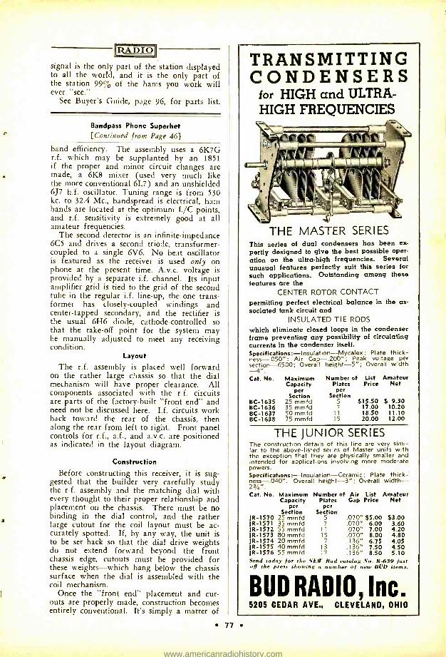
RAE.A0
signal is the only part of the station displayed to all the world, and it is the only part of the station 99% of the hams you work will ever "see."
See Buyer's Guide, page 96, for parts list.
Bandpass Phone Superhet [Continued from Page 46)
band efficiency. The assembly uses a 6K7G r.f. which may be supplanted by an 1851 if the proper and minor circuit changes are made, a 6K8 mixer (used very much like the more conventional 6L7) and an unshielded 6J7 h.f. oscillator. Tuning range is from 530 kc. to 32.4 Mc., bandspread is electrical, ham bands are located at the optimum L/C points, and r.f. sensitivity is extremely good at all amateur frequencies.
The second detector is an infinite -impedance 6C5 and drives a second triode, transformer - coupled to a single 6V6. No beat oscillator is featured as the receiver is used only on phone at the present time. A.v.c. voltage is provided by a separate i.f. channel. Its input amplifier grid is tied to the grid of the second tube in the regular i.f. line -up, the one trans- former has closely -coupled windings and center -tapped secondary, and the rectifier is the usual 6H6 diode, cathode -controlled so that the take -off point for the system may be manually adjusted to meet any receiving condition.
Layout The r.f. assembly is placed well forward
on the rather large chassis so that the dial mechanism will have proper clearance. All components associated with the r.f. circuits are parts of the factory -built "front end" and need not be discussed here. I.f. circuits work back toward the rear of the chassis, then along the rear from left to right. Front panel controls for r.f., a.f., and a.v.c. are positioned as indicated in the layout diagram.
Construction
Before constructing this receiver, it is sug- gested that the builder very carefully study the r.f. assembly and the matching dial with every thought to their proper relationship and placement on the chassis. There must be no binding in the dial control, and the rather large cutout for the coil layout must be ac- curately spotted. If, by any way, the unit is to be set back so that the dial drive weights do not extend forward beyond the front chassis edge, cutouts must be provided for these weights -which hang below the chassis surface when the dial is assembled with the coil mechanism.
Once the "front end" placement and cut- outs are properly made, construction becomes entirely conventional. It's simply a matter of
TRANSMITTING CONDENSERS
for HIGH and ULTRA- HIGH FREQUENCIES
THE MASTER SERIES This series of dual condensers has been ex- pertly designed to give the best possible oper- ation on the ultra -high frequencies. Several unusual features perfectly suit this series for such applications. Outstanding among these features are the
CENTER ROTOR CONTACT permitting perfect electrical balance in the as- sociated tank circuit and
INSULATED TIE RODS
which eliminate closed loops in the condenser frame preventing any possibility of circulating currents in the condenser itself. Specifications : -Insulation- Mycalex; Plate thick- ness- .050 ": Air Gap -.200 "; Peak voltage per section -6500; Overall height -5 "; Overall width --4 ". Cat. No. Maximum Number of List Amateur
Capacity Plates Price Net per per
Section Section BC -1635 25 mmfd 5 $15.50 $ 9.30 BC -1636 35 mmfd 7 17.00 10.20 BC -1637 50 mmfd 11 18.50 11.10 BC -1638 75 mmfd 15 20.00 12.00
THE JUNIOR SERIES The construction details of this line are very simi- lar to the above -listed series of Master units with the exception that they are physically smaller and intended for applications involving more moderate powers. Specifications:-Insulation-Ceramic; Plate thick- ness-.040". Overall height -3 "; Overall width- 23/4". Cat. No. Maximum Number of Air List Amateur
Capacity Plates Gap Price Net per per
Section Section JR -1570 25 mmfd 5 .070" $5.00 $3.00 JR -1571 35 mmfd 7 .070" 6.00 3.60 JR -1572 55 mmfd 11 .070" 7.00 4.20 JR -1573 80 mmfd 15 .070" 8.00 4.80 JR -1574 20 mmfd 7 .136" 6.75 4.05 JR -1575 40 mmfd 13 .136" 7.50 4.50 JR -1576 55 mmfd 17 .136" 8.50 5.10 Send today for the NEW Bud catalog No. R639 just off the press showing a number of new BUD items.
BUD RADIO, Inc. 5205 CEDAR AVE., CLEVELAND, OHIO
77
www.americanradiohistory.com
RADIO holes for the tubes and r.f. transformers, etc. -all items are located in the approximate relative positions indicated in the layout draw- ing. The coupling coils or capacitors may be wired in below chassis or mounted on small male plugs matched to socket -type receptacles positioned between i.f. transformers. Controls may be mounted on the front panel if the r.f. assembly cutout is placed well forward for full dial clearance -or mounted on the front chassis drop if the assembly is to go back a bit and the dial drive weights are to drop into cutouts at the front of the base.
Multi -Wire Type Antennas
{Continued from Page 24]
types and also the delta- matched half -wave antenna. The antennas were tested in a horizontal position about 25 feet above ground. The small circles indicate experi- mental points.
The curves of figure 5 show that both the 2 -wire half -wave and three -quarter wave doublets are almost "flat" or show very little variation in match over the 14 -Mc. band. The delta- matched half wave, however, shows a marked change in standing wave ratio, and at no frequency is the match as good as with the 2 -wire doublets.
We may conclude from figures 4 and 5 that the 2 -wire doublets perform in a very satis- factory manner over a wide frequency range and at various heights above ground. The termination provided by the delta -matched half wave, although much poorer, might be regarded as satisfactory in amateur practice. It is evident from the curves for this antenna that the transmission line is terminated in considerable reactance at the antenna. This condition is not necessarily typical with the delta- matched half wave but was present with the one tested.
"70 -Ohm" Feed
In some locations it may not be convenient to bring a 600 -ohm open -wire line all the way into the station. A flexible cable of about 70 ohms surge impedance might be used to ex- tend from the outside wall of the station to the transmitter. If such an arrangement is desirable, the system shown in figure 6 can be employed.
EVERYTHING IN RADIO! Our immense stock of radio sets,
partsand supplies enables you to pup chase your entlreneeds on one order.
You'll find all your Nationally Known Favorites in this book which is FREE for the asking. Practically every order ship ped same da received. Willi III CATALOG.
BURSTEIN-APPLEBEE CO. 1012.14 McGee Sr. + K C.AV. Mn
78
In this case, a 70 -ohm cable is coupled to the transmitter with a pickup loop. A suffi- cient length of cable is employed to extend outside the station. At this point, a Q sec- tion one -quarter wavelength long is located. This section may be designed to have a surge impedance of about 200 ohms. Either 1/2 -inch (outside diameter) tubing spaced 11/2 inches on centers or 3/g -inch tubing spaced 1 inch should be satisfactory. The 600 -ohm line connects to the far end of the Q section and extends to the multi -wire doublet. Any length of 600 -ohm line can be used.
The pickup loop may be coupled to an auxiliary antenna tank circuit or directly to the final amplifier tank. If an auxiliary an- tenna tank is used, the center of this tank coil should be grounded. If the pickup loop couples directly to the final tank, it is espe- cially important that the loop be of well in- sulated wire. Heavily insulated automobile ignition cable (the type without external shielding) can be employed to advantage. It is also desirable to ground the center of the loop, thus, providing continuous drainage of static charges from the antenna and ensur- ing that the antenna system is always at d.c. ground potential even if the loop should con- tact the high- voltage supply. If this latter should occur, the transmitter fuses will blow or overload relays will open rather than per- mit the d.c. high voltage to appear on the an- tenna system.
2 -Wire Three- Eighths Wave Vertical The multi -wire doublet antennas described
in this article can, of course, be operated either vertically or horizontally, whichever is desired. However, a purely vertical type can be constructed, if one half of the 2 -wire three -quarter wave doublet is turned vertical and operated against ground. Figure 7 shows such a system with dimensions suitable for use on the 14 -Mc. band. The feed point re- sistance is about 250 ohms. To match a 600 -ohm line, a Q section one -quarter wave- length long having a surge impedance of about 390 ohms (number 10 wire spaced 11/2
inches) can be used between the feed point and the 600 -ohm line. However, the standing wave ratio with a 572 -ohm line directly con- nected between the antenna and ground was found to be less than 3.0.
The 2 -wire three -eighths wave vertical an- tenna is midway in height between a half and quarter -wave vertical antenna. With a good ground system, this antenna should be effec- tive when designed for use on either the low or high frequency bands. The distribution of the total current of both wires is shown in figure 7 -B. The total current is in the same phase over the entire length and does not go to zero at any point.
For mobile 56 -Mc. work the antenna could be mounted with the automobile frame as
ti
www.americanradiohistory.com
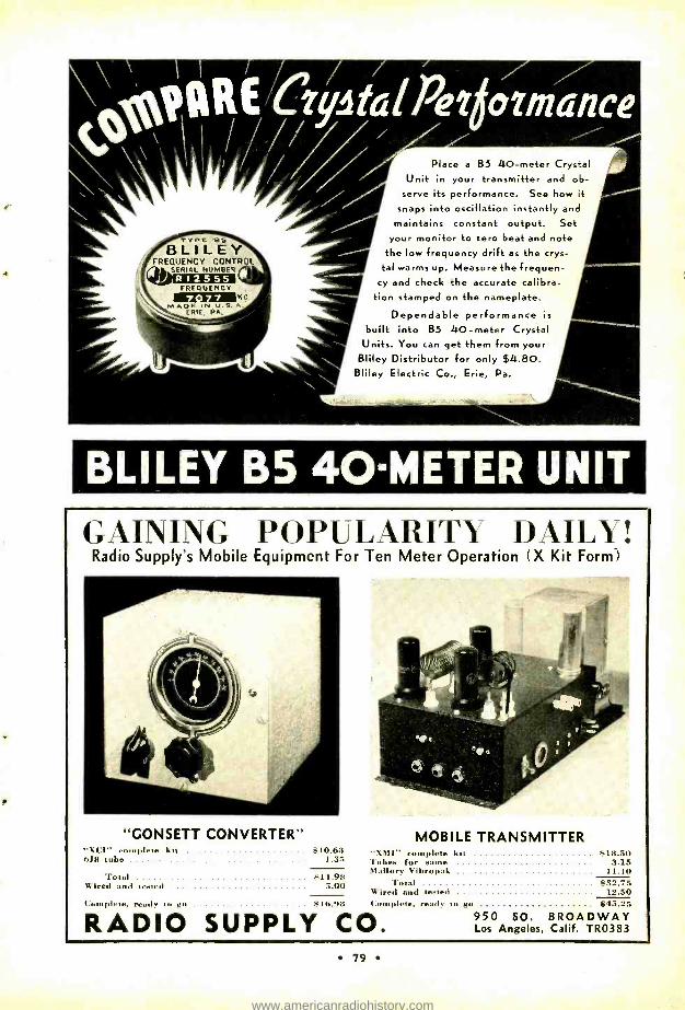
Ty PC 05 BLILEY FREQUENCY CONTROL
SERIAL NUMBER COMM FREQUENCY
KG M A(J U.S, A.
ERR IE, PA,
Place a B5 40 -meter Unit in your transmitter a
serve its performance. See
snaps into oscillation instant! maintains constant output.
your monitor to zero beat and r
the low frequency drift as the et
tal warms up. Measure the freque cy and check the accurate calibre
tion stamped on the nameplate.
Dependable performance is
built into B5 40 -meter Crystal Units. You can get them from your Bliley Distributor for only $4.80.
' Bliley Electric Co., Erie, Pa.
Crystal nd ob- how it y and
Set tote ys-
n-
BLILEY B5 40-METER UNIT
GAINING POPULARITY DAILY! Radio Supply's Mobile Equipment For Ten Meter Operation (X Kit Form)
"GONSETT CONVERTER" MOBILE TRANSMITTER "WI-complete kit 6.18 tithe
$ 10.63 1.35
"XMl" complete kit Tubes for same
$18.50 3.15
Total $ 11.98 Mallory Vibropak 11.10
$32.75 Wired and tested 5.00 Total Wired and tested 12.50
I;ony,lete. read. to co s16!18 I Complete, ready to go $15.25
RADIO SUPPLY CO. 950 SO. BROADWAY Los Angeles, Calif. TR0383
79
www.americanradiohistory.com
DON'T LET IT GET YOU DOWN!
Of course you read the best periodicals covering your own special branch of the Radio field.
But what of the other twenty-nine magazines which cover the other ninety per cent of the increasingly fascinating world of Radio? To be well acquainted with important progress in all these fields would help you to know and en- joy your own specialty even more than you do today.
Today, thanks to Radio Technical Digest, you can keep up -to -the- minute on everything that's happening in radio (except broadcast and entertainment), without spending a fortune in time and money.
Between the covers of this concise, well - written digest, is the technical world at a glance! The outstanding articles of the month in both foreign and do- mestic publications are reprinted or condensed; others reviewed in thumb nail sketches.
RADIO TECHNICAL DIGEST BIMONTHLY
Two years, $2.50 Overseas, $3.00
7460 Beverly Blvd. Los Angeles, Calif.
80
IRADIOi
ground and fed with a 200- to 400 -ohm line. For the 56 -Mc. band the dimensions given in figure 7 should, of course, be divided by 4.
3 -Wire Half -Wave Doublet
As was mentioned in RADIO for May,' the use of 3 closely- spaced in -phase elements results in an even higher current loop re- sistance than when 2 in -phase elements are employed. This principle has been applied in the design of the 3 -wire half -wave doublet shown in figure 8. The dimensions given are satisfactory for the 14 -Mc. band. The spac- ing between elements is 6 inches, making an overall width of 1 foot. The wiring may be either as shown in figure 8 -A or 8 -B, the operation of both arrangements being the same. With the antenna in free space, or very high above ground, the feed point re- sistance is about 900 ohms.
With a 600 -ohm transmission line directly connected to the antenna, the standing wave ratio measured on the line was about 1.5. Accordingly, the antenna can be fed in an entirely satisfactory manner with a 600 -ohm line.
The 3 -wire half -wave doublet operates with a very small change in match over a wide frequency range and at various heights above ground. Thus, it compares most favorably in performance with the 2 -wire half -wave doublet. The only disadvantage is that 3
wires are required instead of 2.
' loc. cit.
Revolving Close- Spaced Rotary [Continued from Page 47]
Various ways of coupling the small bicycle sprocket to the fan's oscillating gear shaft can be found. By extending another plate from the bed plate below the sprocket and then installing another thrust bearing an ex- cellent support and bearing arrangement is had. There is, however, a slipping clutch in the gear mechanism that must be blocked. By driving the two little balls and the spring from the shaft and then inserting a pin, the coupling from the shaft to the sprocket is made positive.
The rotating device is controllable by two push buttons, and it is easy to reverse the direction of rotation by changing two wires from the starting coil to the fan. The drive system has proven itself to be amply strong since in a recent high wind the antenna held in place without stripping the gears or other- wise damaging the mechanism. However, should the gears rip out, they can be replaced easily and at a very small cost.
This novel drive mechanism, aside from being entirely satisfactory, is comparatively
www.americanradiohistory.com
RADIO
inexpensive. An old electric fan of the os-
cillating type usually can be found in a second- hand store or a junk shop. The bicycle sprockets can be obtained from any bicycle repair shop. A large bicycle sprocket was obtained for 25 cents and a small one for 15
cents. It was found advisable to buy a new chain since worn links won't ride so easily on the sprockets.
The accompanying photographs should be practically self-explanatory in furnishing in- formation on how to adapt this mechanism to similar rotary installations. Notice that the whole antenna rests on a pivot bearing. The pipe is held at the crest of the roof by a slipping collar that is secured to the eave.
Since the antenna is not visible from the operating position, an indicating device was made which consisted of a map of the United States with 16 lights around its border. These lights are controlled by a commutator at- tached to the inch- and -a- quarter vertical an- tenna support.
Ultrasensitive 56 -Mc. Receiver
[Continued from Page 37)
the right. The 6F6 pentode second audio tube is seen between the transformer and the 6E5 electric eye.
The R.F. End
It is surprising how little actual wiring is necessary in an r.f. stage of this type. By -pass condensers can be built into the sockets,' in which case they should have a substantial capacity. The small tube clips are insufficient for this purpose. As far as we know, there is no entirely satisfactory acorn socket available at this time. Ordinary condensers do not by- pass effectively above 56 Mc. The under- side photograph, figure 5, shows sockets on the wrong sides of the shield; it is the grid end that should project out the bottom of the sockets into the next compartment. The sockets, or the sockets and the compartment walls to which they are attached, are best made removable to facilitate mounting the tubes without chipping out the seals.
The circuit diagram of figure 6 is fol- lowed. The grid and plate leads to the r.f. tube can be run on insulated wires through the inner conductor, making parallel feed possible without chokes or condensers, except for the decoupling at the shorted end of the line. With cathode bias as shown, the grid connection can be made directly to the inner conductor. The small trimming condenser on the first line makes up for the plate capacity that is present on the mixer line but not on the antenna or input line. This is help- ful in tracking these circuits.
New . .
ANTENNA RELAYS by
Guardian
TAKE A POWER DIVE!
Good news . startling news . . . so good you might even become skeptical. But it's true .
Guardian answers the amateurs need with these low- priced A -100 Antenna Relays. Tested under actual operating conditions these new A -100 An- tenna Relays by Guardian have proved themselves capable of handling any power up to a K.W. on any frequency up to and including 28 Mc. on A.F. or R.F. circuits. These A -100 Antenna Relays by Guardian give you more for less.
oar& Standard A -100 and A -100 -C Antenna Relays AlSiMag in- sulated. Operate on 100 V.- 60 cycle A.C.
LIST PRICES A -100 Double Pole Double Throw A -100 -C Single Pole Double Throw R -100 -C Triple X Insulated
11 rite for ew Bulletin "B" and Circuit Dingrtm,.. ;You'
$5.95 $3.30
$5.00
GUARDIAN ELECTRIC 1631 W. Walnut St.
81
Chicago, III.
www.americanradiohistory.com
RADIO R.F. Biasing
A change that has not been made but which appears advisable is the elimination of cathode bias, substituting bias cells, battery, or bias from the power supply. It is too difficult satisfactorily to by -pass the cathode resistor, making for oscillation; and even a slight amount of inductance in the cathode lead, common to plate and grid circuits, is unde- sirable.' The grid and plate r.f. circuits should be returned as close to the cathode as possible.
954 Mixer The mixer has been tried only with sup-
pressor injection. RCA 954 tubes were found to give better gain both here and in the r.f. stage than 956 s. They operate very well as mixers at this frequency, and have been recom- mended by RCA for the purpose. With suppressor injection and a 955 triode oscil- lator, there is a slight amount of "pulling" of the oscillator frequency when the mixer is tuned through resonance; this amounts to about a half kilocycle. It is noticeable only when using the beat oscillator but probably not even then if the oscillator is ganged with the other circuits. A pentode oscillator of the electron -coupled variety, or better isola- tion and decoupling than we used, may be sufficient to eliminate the slight pulling.
TRANSOIL for transen tong
HIGHEST QUALITY OIL CAPACITORS
Write for Catalog 2 -X
listing complete lines TRANSOIL -SOLAREX -TRANSMICA
SOLAR Cs-) 599 BROADWAY MEG, CORP NEW YORK CITY
82
Any oscillator tube can be used, presumably, although stability is better with the acorns that do not load the tuned circuit heavily.
The oscillator coil used in this receiver was wound with no. 12 tinned wire, 8 turns on a 1/2 -inch diameter, winding length 11/8 inches. The cathode tap is 21/4 turns from the grounded end. This coil may have to be changed to make the circuit track with the others if it is to be ganged. There are sev- eral ways that a concentric line can be used without requiring a cathode tap, the most promising of which appears to be an untuned- grid tuned -plate circuit, or its equivalent with the line in the cathode or screen, to leave the plate free for electron coupling. If the cathode method is used, the heater leads can be brought up through the inner conductor, the cathode hooked to the inner conductor without a by -pass to ground. The grid coil can be self- resonated to about 58 Mc.
The plate and screen voltages on acorn tubes, particularly pentodes, should be held below rating in order to assure long life. Spacing is so close that a little extra heat may allow grids to weld together if there is any vibration; and too much plate or screen current is to be avoided.
I. F. Amplifier This receiver uses standard 3500 -kc. i.f.
transformers. The 6K7 tubes were replaced with 6S7's which seem to be a little better, but single -ended 6SK7's are recommended to keep all r.f. leads within the chassis. Some trouble with oscillation in the i.f. system was cured by grounding the tube shields directly at the sockets instead of on a ground bus.
Diode and A.V.C. Only one diode plate is used. It made no
difference when a 6H6 diode and 6C5 audio were replaced with a single 6R7, except that we accidentally brought the diode return to the wrong side of the audio cathode bias re- sistor, placing bias on the diode, which cut off all weak signals and set noise.
The a.v.c. is straightforward. While the electric eye is a convenience, the a.v.c. has not yet been of value. Possibly with fading dx signals during the summer, it will be more helpful. The r.f. and mixer tubes, which are of the sharp cutoff type, do not receive a.v.c. voltage.
The audio needs no comment. The pentode second stage is used only for speaker recep- tion.
Beat Oscillator A single -ended 6SK7 pentode was selected
for the beat oscillator, to provide electron coupling without having a grid lead hanging out in the air. If this circuit and the first stages are adequately decoupled and shielded, there will be no trouble with harmonics. We
www.americanradiohistory.com
[RADIO coupled the oscillator to the diode plate through a condenser made by twisting in- sulated wire together, but apparently not even this much coupling is necessary. In order to cut down the oscillator output to eliminate harmonics, we put resistors from screen to ground to reduce screen voltage. When the voltage was as low as it would go without stopping the oscillation, the same thing was tried with the plate. Possibly the screen volt- age could then have been reduced further but we have not done any more with it. The voltages cannot exceed 2.5 and 7 with the present resistors. With a 3500 -kc. oscillator, the harmonics fall almost the width of the band apart, so are not troublesome. Still, they can be heard weakly even with this low power oscillator, which speaks well for the sensitivity of the front end. There is some- thing to be said for a 4 -Mc. i.f. using the harmonics of the b.f.o. for band markers.
Decoupling No clearly defined need for decoupling was
encountered, but possibly because it was liber- ally included in the circuits. That it is not yet complete is indicated because the set will pick up a local oscillator signal (through the power supply or other leads not completely shielded). This is not a "trouble," however, because it never shows up in normal opera- tion.
The idea in decoupling is to provide two paths for r.f. from each hot lead -one low reactance path through a by -pass condenser to ground, as an alternative to the other high reactance or resistance path to the power sup- ply source. It reduces or eliminates coupling through the supply leads. To make it most highly effective, a series resistor in each sup- ply or bias lead should be by- passed on both sides to ground, preventing pick -up of radi- ated energy on the supply lead from backing up into the tubes. The decoupling resistor at the shorted end of the pipes could be by- passed again on the power supply side; the same with the other acorn screen and plate decoupling resistors, and those on the beat oscillator. No additional precautions are necessary on the i.f. stages, though.
Power Supply
A voltage regulated power supply has been used, but with the acorn tube oscillator, it is not clear that the excellent regulation and stabilization is necessary. The voltage ad- justment can be varied considerably without altering the oscillator frequency. The regu- lator does improve the filtering substantially; hum is heard when the neon tube goes out. Also, noise due to line surges seems to be eliminated. A 6SJ7 instead of 6J7 will make the dangling grid lead unnecessary.
«;; erihimpl. r:r:,ir ! J
A
In the Custom built all band transmitter of Barker Williamson, Cardwells are used thru -out. Single Trim -airs in the Xtal and buffer stages and that prime favorite, the MT- 100 -GD for the final. The smart bracket arrangement permits all band coverage with the one condenser in the final, using standard B Ir W coils. Pro- viding a tank circuit without leads, these brackets will be heard from again. The neutral- izer for the Taylor T -40 is a Cardwell ZS -7 -SS.
B
In that very popular Stancor 20 -P, two Cardwell Dual Trim -airs are ingeniously made to supply proper capacity values for optimum "Q" for every amateur band from 5 to 160 meters inclusive. Lowest losses and minimum capacity values dictated the inevitable choice of Cardwells.
C
In the 100 -T, by Harvey Radio Labs., a Cardwell MT -50 -GS and an XR- 1000 -PS provide a highly efficient final tank condenser and antenna matching capacitor to handle with- out losses an output of 100 watts on phone.
These nationally known manufacturers invite your permission to send you complete informa- tion on the products illustrated.
"CARDWELLS for every purpose" are available at all amateur supply houses
When in doubt, play safe with CARDWELL
THE ALLEN D. CARDWELL MANUFACTURING CORPORATION 85 PROSPECT STREET, BROOKLYN. NEWYORK
83
www.americanradiohistory.com
RADIO Adjustment
This set was first lined up by touching the second i.f. tube grid, thus bringing in 80- meter signals, and tuning the following i.f. transformer. Tuning is surprisingly sharp. Then the stage ahead is touched and another i.f. transformer tuned, and so on. The re- ceiver can be lined up more conveniently if another receiver that can tune to the i.f. is available. The first detector grid clip is re- moved on the separate receiver and connected to the grid of the second i.f. tube on the 56- Mc. job. When the two chassis are con- nected together, a signal can be run through the second i.f. and detector, and the trans- former can be adjusted. The receiver can then be moved up to the first i.f. and the operation repeated on the middle i.f. trans- former, and the same on the mixer.
Then the r.f. end can be attacked. In test- ing, we used the front end as a converter for the separate receiver, just hooking onto the grid cap of the r.f. tube in the separate re- ceiver. When the oscillator and mixer tun- ing were adjusted, tube noise could be heard with the i.f. wide open. The r.f. stage brings up the noise enough to close the electric eye, so the gain can be decreased substantially for the same signal level.
The antenna coupling is adjusted for best signal. For this purpose, an oscillator set up one or two hundred feet away is very help- ful. Of course, a properly tuned antenna is a great help, and may mean the difference be- tween hearing 20 miles or 150 miles fairly consistently; an improved receiver may be of excellent sensitivity, but when it will go down to the noise level in the first tuned circuit, additional improvement must come by increas- ing the signal fed into the first circuit.
No noise silencer was incorporated in the original model but with as much "hop" as the set has, one will probably operate very satisfactorily.
AMERICAN MICROPHONE CO., Inc. 1915 So. Western Ave. Los Angeles, Cal.
D6T DYNAMIC Microphone Sturdy, Multi -use,
Quality Microphone with Higher Output and
advantageous Directivity Characteristics.
Output level -46, usable range 30 -7000 cps.
D6T, High Imp., $27.50 D6, Low Imp., $25.00 Including Cable
General catalogue describes other attractive models. Request copy.
84
Whether used as a converter, superheter- odyne, or superregen, the acorn and concentric line combination, at least for the first stage, seems destined to replace all other tubes and circuits in u.h.f. receivers which have any claim to being "sensitive."
See Buyer's Guide, page 96, for parts list.
What's New in Radio
[Continued from Page 67]
With the control switch in the unidirectional position, the instrument picks up only sounds reaching the front, or live side -turning a deaf ear to those emanating from any other angle. As a bidirectional microphone, it performs like an ordinary velocity instrument, being responsive on only two sides. In the third position, the control switch permits sounds coming from any angle to be picked up.
The microphone is actually two mikes in one - a bidirectional velocity microphone and a non- directional pressure instrument. The output of each comes down to the control switch, which cuts in one or the other, or both. When the two are connected in series, they give the unidirectional response.
Its directional characteristics are uniform at all frequencies, an advantage which has come to be accepted by many engineers as exclusive with velocity -type microphones. This has been accom- plished in the 77 -C by using ribbon units for both the velocity and pressure sections. The 77 -C microphone has a uniform frequency response from 40 to 10,000 cycles. In spite of its small size and light weight a high order of sensitivity ( -62 db for a 10 bar signal) has been achieved through new structure design and the use of new magnet material.
TRANSFORMER ENCYCLOPEDIA
A new supplement to the Thordarson Replace- ment Transformer Encyclopedia No. 243 is now ready for the serviceman. The supplement, No. 243 -D, gives complete information regarding the correct placement power transformer, filter choke, audio or output transformer for all 1938 -1939 receivers as listed in Rider's Manual Vol. IX.
Copies may be secured free of charge from any Thordarson distributor, or will be mailed direct from the Thordarson Electric Mfg. Co., 500 West Huron, Chicago, Ill.
It Works . . . Sometimes!
It seems that the F.C.C. has now adopted the time -honored amateur practice of "pour- ing on the coal" to eliminate interference. The Commission has authorized WTAR to in- crease power to 5 kw. at night in order to overcome interference from Cuban CMQ, which operates on the same frequency. If this keeps up the broadcast band will sound like the high- frequency end of 20 during a contest.
www.americanradiohistory.com
IIZADIO
Remote Control of E.C.O. {Continued from Page 503
with a bakelite disc three inches in diameter and one- eighth inch thick, two small rubber feet (of the type generally used as shock mounts on b.c. chassis) about 3/4 inch in diameter with 1/4 -inch hole, one 1/4 -inch shaft bushing, one bushing and shaft made as a unit, one old mike spring, and an aluminum condenser plate. The bakelite disc served as a pulley after a groove had been turned on its outside edge. The rubber feet served as a small pulley for friction drive against the metal dial on the shaft of the e.c. band - spread condenser.
The three -inch bakelite disc and the rubber drive wheel for the dial are mounted upon opposite ends of a 1/4 -inch shaft with a bear- ing between the two. The bearing (which is one of the inexpensive through -panel type) is in turn fastened to a piece of brass strip three inches long. The other end of the shaft is fastened to a shaft which passes through another panel bearing. This as- sembly forms a flexible arm on which the bakelite disc and the rubber drive wheel are mounted.
The aluminum condenser plate is cut and made fast under the panel bearing. A small lip is turned up on one end and a small hole is drilled therein where one end of the spring is hooked. The other end of the spring is hooked through a hole in about the center of the brass arm. A piece of fishing line is then used as a belt from the shaft of the driving motor to the bakelite disc. It is ap- parent from the photograph that the spring serves to keep tension on the belt as well as to hold the rubber driving pulley tightly against the metal dial.
Of course it is obvious from the make shift nature of the driving system that it could be considerably improved, but the fact that the system has proved satisfactory over a period of time indicates that the basic ideas therein are sound. It is quite possible to simplify the drive system and hence to make it very much more compact.
Operation The filaments of the transmitter are turned
on and the transmitter is made ready for operation by closing the main line switch to the shack which is located at the operating position. A check over the band indicates that it is pretty much a solid mass, but at last a spot is found where the QRM is a little less severe. By throwing S. either one way or the other (depending upon which way it is desired to QSY) and by listening to the re- ceiver with the beat oscillator operating it will be possible to hear the exciter when it is tuned to the desired frequency of operation.
The bandspread condenser of the e.c.o. is
d N fD 71 íZ1,d
W aN 77 wNN ; I a ,
2314 am00
ry Ç . 3W O C
Ná°m3: j a p 3 o Or 33 ,^a Ñd
o m n D a ° . ;.3?.?,* m'3 n 'm m to 0-3 2 7O CD 3 .T, C p.ti,pgm p
Ñ r ñOT m F<< doD oom 7adC7 Z Ç7-n
m -4 an
a »
«
` -
o
+
z 3 n 2. v, >w
3. oF ú s F s F
e T + ' á ' ^ 3 ' < _
V" 12 =
F Ñ
2 -2°15m2..7' rn ' m
1D T~ m n v F c a ó Ñ o á m í MIR m ' Á n
=
Á
Ñ
s D s ° m F
^
m
d
Á ' ó
^ é:d
7"V:41/174.:;74 n n o^ g X° ó A' + 0 3.-';. ° Ng o. 4 ñ ó
m + á ó n < 3
Ñ m
n m é ó F°m .0 S! ry S o + C
F Ñ
A 3 o M S C O, ^ _ _
a
ÿ cgcG
v d+mm d° ó
m
0
Á uP _ a _ : ^ ÿ ' 71;
,1 ó
s 3°: v1 I"; 3 F 3 ' D 7
Ñ 3- aa w o ¿d ä;
3 Z. - n
o, m ö'° rn P m 00 3
3 b Á á 7» d n A O' d' W b'; 3. W 7 Q
A ñ m w .^.
m' ~ T C. 1° C p?r
3 s : S ÿ d
S F V - p A C
O. x' s. ö z o 3 _. ó m mm °
85
www.americanradiohistory.com
RADIO
so adjusted that a full 180° of rotation will not change the frequency further than a safe margin within the edges of the band of oper- ation. Therefore, should the condenser be rotated through a full 360° the signal will not wander outside the band but will only tra- verse it twice. With the gearing arrangement shown approximately 20 seconds are required to QSY from one end of the band to the other.
By referring to the diagram it will be seen that the switch S. reverses the polarity of the relay battery, thus causing the polarized re- lay (1) to throw either one way or the other. Relay (2) then closes and applies the 110 a.c. to the primary of the transformer that supplies the motor; the motor then rotates in either one direction or the other depending upon which way the polarized relay has been thrown. Relay (4) also closes when the 110 is applied across it and applies plate voltage to the exciter stages of the transmitter. This allows the signal from the exciter stages to be monitored while the QSY is taking place. Of course the final is not on the air during QSY and by the same token QSY cannot take place when the final is on the air. Opening switch S. to the neutral position after the transmitter has been tuned to the desired frequency and closing Si will place the rig on the air for normal operation on the new frequency.
Your Inquiries Invited When you need amateur equipment it is to your advantage to write to me. You get per- sonal attention; 6% terms financed by myself so you buy with less cost and more conven- ience; fair trade -in value for your equipment; ten day trial of all receivers; and my coopera- tion in every way to see that you are 100% satisfied. For any equipment, the latest in- formation and technical help, write to W9ARA.
Compare My Terms with Others ñlalel and Receiver
lash l)oam 1_.Aloo16I l'. i I'r.>nuent l'a ;ila,11
The new SX -23 $115.50 $23.10 $8.16 RME -70 138.60 27.72 9.79 HQ -120X and NC1O1X 129.00 25.80 9.11 NC100A 120.00 24.00 8.48 NC8OX and NC81X 99.00 19.80 6.99 Breting 49 and 516 99.00 19.80 6.99 Howard 438 49.95 9.99 3.53 NC -44 and S -20 49.50 9.90 3.49
Also HRO, Breting 9, Howards, Sargents, all others
Similar terms on Hallicrafters, National. Harvey, RCA, RME, Temco transmitters and Thordarson, National, U.T.C., Utah, Kits,
Ast"Ax% W9ARA
BUTLER MISSOURI
86
Open Forum
[Continued from Page 66]
European delegation simply "muscled in" and took 7200 -7300 kc. for themselves.
In the fall we can expect a tremendous influx of high -power European broadcasters. If they find they can do a good job of getting out on these frequencies, I doubt if there will be any 40 -meter amateur band at all after the Rome convention -let alone a 7200 -7300 kc. band.
If 7200 to 7300 kc. is to be a broadcast phone band, then let's fight fire with fire. Why not ask the F.C.C. to designate this strip of territory for amateur phone as well?
Yes, I know there will be loud cries from the c.w. brethren. But I think that the future of the 40 -meter band is at stake. I've never before advocated phone on the 7 -Mc. band, but I think that under the circumstances it would be an advisable expedient.
Remember what the 160 -meter phone men did? They occupied this band after it had been deserted by the c.w. fellows. Had they not done so, you can bet your last dollar that the 160 -meter band would now be full of commercials and gone from the amateurs forever.
It must be admitted that some of the 160 - meter phones were a bunch of lids who couldn't read code well enough to keep pace with the traffic men and old time dxers. But they saved the band, and I think the phone men can do the same for 40 meters.
Jay C. Boyd, W6PRM
75 -M. Fone DX
North Island, New Zealand Sirs:
We here in New Zealand hear a large num- ber of W and VE 75 -meter phone stations in the early evening, and again between 11 p.m. and 2 a.m., sometimes as late as 4 a.m. in the early morning here. Your 75 -meter phone band is quite clear of heterodynes, and there is no reason why your W stations can't con- tact more ZL's at that time.
One point I would like to bring to your notice is that we here in New Zealand are allowed phone between 3500 kc. and 4000 kc., and if you fellows care to look outside your band there is no reason why you cannot make more ZL contacts on 75 meters.
ZL2BN on 3964 and myself on 3931 kc. are on each morning, looking for dx. We hear Wl, 2, 3, 4, 5, 6, 7, 8, 9, VE5, 4 and sometimes VE3, KAI, XE and K7 once in a while.
Some of your sigs reach R8 here and 100 per cent copy between 12 midnight and 7 a.m. your time. VK3WE is on 3662 kc. and re- ceives you boys well in Omeo, Victoria, Aus-
www.americanradiohistory.com
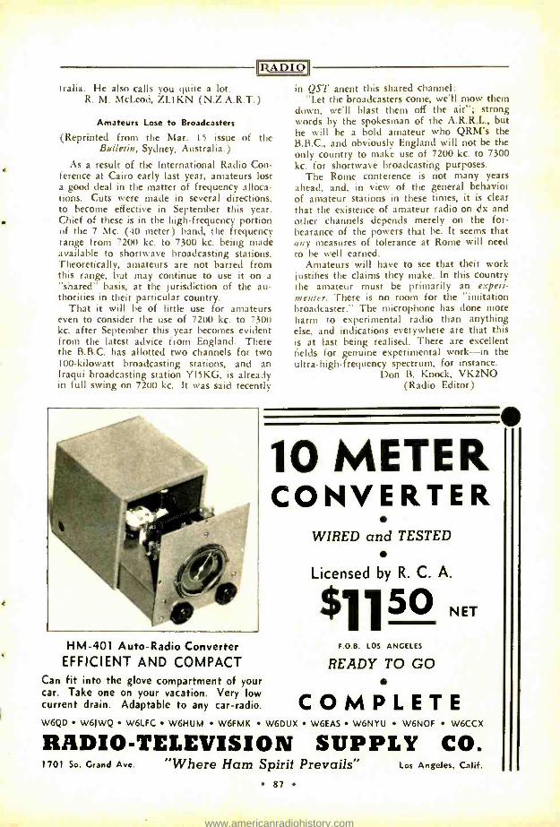
ItA1)I()
tralla. He also calls you quite a lot. R. M. McLeod, ZL1KN (N.Z.A.R.T.)
Amateurs Lose to Broadcasters
(Reprinted from the Mar. 15 issue of the Bulletin, Sydney, Australia.)
As a result of the International Radio Con- ference at Cairo early last year, amateurs lost a good deal in the matter of frequency alloca- tions. Cuts were made in several directions, to become effective in September this year. Chief of these is in the high- frequency portion of the 7 Mc. (40 meter) band, the frequency range from 7200 kc. to 7300 kc. being made available to shortwave broadcasting stations. Theoretically, amateurs are not barred from this range, but may continue to use it on a
"shared" basis, at the jurisdiction of the au- thorities in their particular country.
That it will be of little use for amateurs even to consider the use of 7200 kc. to 7300 kc. after September this year becomes evident from the latest advice from England. There the B.B.C. has allotted two channels for two 100- kilowatt broadcasting stations, and an Iraqui broadcasting station YI5KG, is already in full swing on 7200 kc. It was said recently
HM -401 Auto -Radio Converter EFFICIENT AND COMPACT
Can fit into the glove compartment of your car. Take one on your vacation. Very low current drain. Adaptable to any car- radio.
n QST anent this shared channel: "Let the broadcasters come, we'll mow them
down, we'll blast them off the air "; strong words by the spokesman of the A.R.R.L., but he will be a bold amateur who QRM's the B.B.C., and obviously England will not be the only country to make use of 7200 kc. to 7300 kc. for shortwave broadcasting purposes.
The Rome conference is not many years ahead, and, in view of the general behavior of amateur stations in these times, it is clear that the existence of amateur radio on dx and other channels depends merely on the for- bearance of the powers that be. It seems that any measures of tolerance at Rome will need to be well earned.
Amateurs will have to see that their work justifies the claims they make. In this country the amateur must be primarily an experi- menter. There is no room for the "imitation broadcaster." The microphone has done more harm to experimental radio than anything else, and indications everywhere are that this is at last being realised. There are excellent fields for genuine experimental work -in the ultra -high- frequency spectrum, for instance.
Don B. Knock, VK2NO (Radio Editor)
10 METER CONVERTER
WIRED and TESTED
Licensed by R. C. A.
$11 5° NET F.O.B. LOS ANGELES
READY TO GO
COMPLETE W6QD W61WQ W6LFC W6HUM W6FMK W6DUX W6EAS W6NYU W6NOF W6CCX
RADIO -TELEVISION SUPPLY CO 1701 So. Grand Ave "Where Ham Spirit Prevails"
87
Los Angeles. Calif.
www.americanradiohistory.com
ADIO The Amateur Newcomer [Continued from Page 62]
coupling circuit through resonance without pulling the oscillator out of oscillation. The dial light should increase in brilliance as the antenna circuit is tuned up to resonance and then decrease as it is detuned on the other side.
When this condition is obtained, remove the dial lamp from the antenna and make the antenna connection directly to the antenna post. Then, without touching the antenna - tuning condenser, turn the plate condenser to- ward maximum capacity until the point of maximum capacity at which the circuit will still oscillate is found. The final adjustment of the plate condenser should be made while listening to the signal from the transmitter in a monitor or receiver. The condenser should be set at the furthest point toward maximum capacity at which the keying is clean and dis- tinct without chirps or lag.
The farther down the plate coil the coup- ling link is placed, the looser the coupling to the antenna circuit. If the coupling is too tight, the oscillator won't oscillate or the note will be chirpy. If the coupling is too loose, the full power will not be delivered to the antenna.
Buy a Fresh Copy Today
of the
RADIO AMATEUR CALL BOOK
The CALLBOOK is the only publication that lists all licensed radio amateurs in the United States and over a hundred and seventy -five different foreign countries. Each issue also contains a world map showing amateur prefixes, press, time and weather sched- ules, amateur prefixes listed alphabetically and by countries and a world time conversion chart.
Complete ... Accurate ... Up -to -Date
Issued Quarterly MARCH . . . JUNE . . . SEPTEMBER and DECEMBER
Annual subscription $4.00 Single copies $1.25
Buy your copy now from your radio jobber or direct from:
RADIO AMATEUR CALL BOOK, Inc. 608 S. Dearborn St. Chicago, III., U. S. A.
88
The coupling should be adjusted by varying the position of the plate coil coupling link, never by detuning the antenna condenser. The latter should always be tuned to resonance. If it cannot be tuned to resonance without the transmitter's going out of oscillation or de- veloping keying chirps, the coupling is too tight.
If the dial lamp in the antenna lead does not give sufficient indication to be observed handily, a 2 -v. 60 -ma. bulb may be substi- tuted. The 6.3 -v. 150 -ma. type may be pur- chased under the following type numbers: 40, 40 -A, and S -47. The 2 -v. 60 -ma. type is
known as the type 48 or 49, depending upon the type of base.
Do not use a 60 -ma. lamp unless you are unable to get a satisfactory indication on a
150 -ma. bulb. The maximum antenna current will be low at this point (a current "node") and will vary somewhat in different antenna installations, due to a difference in radiation resistance. The latter depends upon height of the antenna above ground, etc.
40 -Meter Tuning Procedure On 40 meters the tuning is somewhat sim-
pler, because the transmitter acts as a regen- erative harmonic oscillator and will oscillate and key cleanly regardless of how heavily the plate circuit is loaded. Therefore it is neces- sary only to tune for greatest output, without regard to keying chirps or non- oscillation.
On 40 meters, with the antenna circuit un- coupled or detuned, the cathode current will "dip" about 20 ma. when the plate condenser is tuned through resonance. Resonance is ob- tained when the condenser is tuned to the "bottom of the dip." Keep increasing the an- tenna coupling and readjusting the antenna condenser to resonance until the meter shows a dip of only 3 to 5 ma. as the plate con- denser is tuned through resonance. This ad- justment corresponds to maximum output. The flashlight bulb is not necessary for tun- ing up on 40 meters, but is somewhat of a
help because maximum indication will be ob- tained with the adjustments just described.
With the power supply specified, the cath- ode current will run around 70 ma. on 80 meters and about 75 ma. on 40 meters. These are typical readings obtained under correct operating conditions. However, one should not assume that the rig is tuned up correctly just because these meter readings are obtained, or incorrectly because it is 5 ma. lower or higher than these values. The procedure de- scribed should be followed religiously and the final value of cathode current obtained be considered merely a check on the procedure.
Danger The danger of shock has been minimized in
this transmitter by incorporating a front panel in preference to usual "breadboard" construc-
www.americanradiohistory.com
RADIO tion, and using a circuit which puts neither the meter, coils, nor condenser shafts at posi- tive potential. While the voltage and current delivered by the power supply used in con- junction with this transmitter are not high enough to be considered lethal under ordinary conditions, electrocution is possible. For this reason the beginner should learn to show a wholesome respect for high voltages without first having to get "bit" a few times. Keep in mind that sometimes the first time is the last.
See Buyer's Guide, page 97, for parts list.
Radio as a Profession [Continued from Page 25]
This opens up numerous opportunities to earn money and experience in connection with his college education. During the vacation months there is a chance not only to earn a substan- tial sum, but to travel as well. The ideal vacation occupation for the student operator is aboard a private yacht. Alternatives in- clude tramp steamers, excursion boats, shore stations or airway positions. Many amuse- ment parks require public address operators for the summer.
There are splendid opportunities for am- ateurs to earn money in spare time servic- ing broadcast receivers, public address sys- tems, electrical appliances, talking motion pic- ture equipment and even automotive electrical units. Additional money can be earned re- tailing broadcast receivers on a small scale.
Returning to the matter of a college edu- cation, possibly the most important subject in connection with radio is mathematics. The modern physicist, scientist and engineer thinks in terms of mathematics. It is truly said that if one understands higher mathematics, then "everything is obvious." Aside from the higher mathematics including advanced algebra, geometry, quadradic equations and calculus, the supplementary subjects will de- pend upon what one intends to specialize in. The specialist in acoustics will be required to design broadcast studios, amplifiers, loud speakers and microphones. The prospective tube engineer should study metallurgy, chem- istry, thermodynamics and physics as well as electrical engineering. The transmitter and receiver engineers have to study high -fre- quency and ultra -high- frequency alternating currents in addition to electrical engineering.
The engineering student holding one or more degrees and completing a year or two of graduate study specializing in some one branch of radio can look forward to imme- diate employment. Manufacturers are always looking for new, promising talent, young am- bitious men that have the proper fundamental education. Aside from the manufacturers of radio and electronic apparatus, other employ-
N\ May
mploy-
May we suggest
A SAFETY RELAY? The new Ward Leonard Safety Relay is an essential piece of equipment. It automatically discharges the built up high voltage in filter
condensers. This relay pro- tects the operator . . . it
protects the set. Full in- formation in data sheet No. 5070.
Ask your supplier about the new low prices of Ward
Leonard Relays.
Send for Data Sheet No. 5070
WARD LEONARD ELECTRIC COMPANY 29 South Street Mount Vernon, N. Y. t will
pay you . to write to me whenever you want to huy an Amateur Receiver. Television Receiver, Transmitter. or any other equipment. More and more men, since 1925, have been buying their supplies from me and that's a sure sign that I give a. fair and square deal, every time!
My personal attention to your wishes, fair trade -in al- lowances, reasonable terms for your convenience, prompt safe delivery, and above all -a sincere desire to give you full co-operation-is your assurance of complete and last- ing satisfaction.
Be sure to write to me. 73 tll ciarrison, W2AVA
Authorized Factory Distributor of all
AMATEUR RECEIVERS
"Ye Trading Post" (My Used Dep't) has many good reconditioned and
guaranteed trade -in Receivers and Transmitters at at tractive prices. Good values! Send stamp for list.
So many of my Amateur customers are also
CAMERA FANS that I have put in a large stock of cameras. enlargers, film, accessories, and supplies. I call
this my
CAMERA DIVISION and I welcome your inquiries and orders.
HARRISON RADIO CO. 9 West Broadway, New York City
89
www.americanradiohistory.com
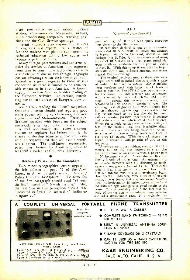
[RADIO
ment possibilities include motion picture studios, communication companies, airways, radio broadcasting companies, teaching posi- tions and the Civil Service openings.
Patent attorneys also require the services of engineers and experts. As a matter of fact the student may plan to supplement his technical education with a law course and become a patent attorney.
Many foreign governments and concerns re- quire the services of American radio engineers from time to time. The radio engineer with a knowledge of one or two foreign languages has an advantage when such openings occur. Spanish is a good language to know in. this connection as there is bound to be consider- able expansion in South America. A knowl- edge of French or German enables reading of the European technical publications, permit- ting one to keep abreast of European develop- ments.
Aside from reading the "ham" magazines, the radio amateur should read regularly good trade papers relating to electronics, electrical engineering and communication. These pub- lications together with books on the subject are available in most public libraries.
A real opportunity that every amateur, student or engineer has before him is the chance to develop something new and valu- able, an improvement that will rate a worth- while patent. The well -known regenerative patent was obtained by Armstrong while he was still a student at Columbia University.
Receiving Pulses from the Ionosphere
Two minor typographical errors appear in the left column on page 72 of the April RADIO, in A. W. Friend's article, "Receiving Pulses from the Ionosphere." The sixth line of the first paragraph should read "11 with the line" instead of "10 with the line." Also, the last line in this paragraph should read "indicated in figure 10" instead of "indicated in figure 11."
U.H.F. {Continued from Page 65]
good coverage of 10 miles with spotty reception possible up to the 18 -mile radius.
"It was then decided to put on a transmitter with about 40 or 50 watts of power and attempt to transmit signals to Conneaut, Ashtabula, and perhaps into Buffalo. A rig was constructed using a pair of RCA 834's in a tuned plate, tuned fila- ment oscillator, modulated with a pair of 1720's in class B. With this setup it was possible to put 40 watts into a simple dipole antenna, and secure a good 25 -mile coverage.
"The original receivers used in these tests were simple acorn self -quenched detectors with a stage of audio. There are no special tricks in making these receivers perk, only keep the r.f. leads as short as possible. The HY -615 may be substituted for the acorn. A later receiver was constructed with a separately quenched detector and an r.f. stage. In getting this receiver to work, there seemed to be only one point worthy of note. The r.f. stage was originally built with cathode bias but tests showed that this stage was unstable. This may be attributed to the fact that the by- passed cathode resistor presents considerable impedance and perhaps a bit of inductance at this frequency. When the cathode resistor was replaced with grid bias of the battery type, this instability disap- peared. Plans are now being made for the con- struction of a receiver using concentric lines in the tuned r.f. stages. With three r.f. stages it is hoped to 'secure a voltage gain of 200 at this frequency.
"Antennas are a big problem, even on 10 and 5
meters, but on 11/4 they become so small that the construction of an antenna with a power gain of 20 becomes simple. A radiator at this fre- quency is only 26 inches long. An antenna using six driven elements with six directors at tenth - wave spacing gives a gain of 13 db. This is the radiator that is in use at the present time. The first car antenna used was a three -element beam, close spaced. However, after a series of experi- ments, it was found that a quarter -wave Marconi mounted horizontally 48 inches above ground and fed with a single wire gave as good results as the beam. This is probably due to the fact that the body of the car acts as an infinite plane reflector and adds considerable gain. It is probable that
A COMPLETE UNIVERSAL PORTABLE PHONE TRANSMITTER Send for complete
perifìrations
NET PRICES (F.O.B. Palo Alto, less Tubes, Mike, Xtals.)
Type 10 -Z-6 V. D.C. & 110 V. A.0 $105.75 Type 10 -AV -12 V. D.C. & 110 V. A.C 120.75 Type 10 -AW -32 V. D.C. & 110 V. A.C 120.75 Type 1 -C -Push to talk mike 10.50
10 TO 15 WATTS CARRIER
COMPLETE BAND SWITCHING - 10 TO 160 METERS
BUILT -IN UNIVERSAL ANTENNA COUP- LING NETWORK
5 BAND COVERAGE ON 2 CRYSTALS
CAN BE USED AS A BAND SWITCHING EXCITER FOR THE BIG RIG.
KAAR ENGINEERING CO. PALO ALTO, CALIF., U. S. A.
e 90
www.americanradiohistory.com
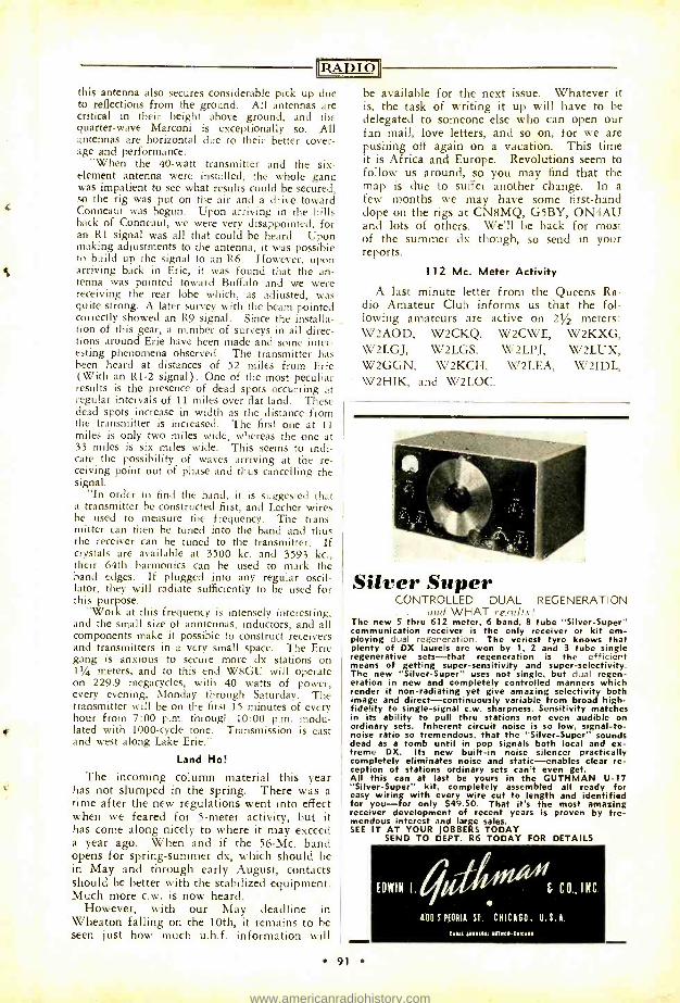
O
this antenna also secures considerable pick up due to reflections from the ground. All antennas are critical in their height above ground, and the quarter -wave Marconi is exceptionally so. All antennas are horizontal due to their better cover- age and performance.
When the 40 -watt transmitter and the six - element antenna were installed, the whole gang was impatient to see what results could be secured, so the rig was put on the air and a drive toward Conneaut was begun. Upon arriving in the hills hack of Conneaut, we were very disappointed, for an R1 signal was all that could be heard. Upon making adjustments to the antenna, it was possible to build up the signal to an R6. However, upon arriving back in Erie, it was found that the an- tenna was pointed toward Buffalo and we were receiving the rear lobe which, as adjusted, was quite strong. A later survey with the beam pointed correctly showed an R9 signal. Since the installa- tion of this gear, a number of surveys in all direc- tions around Erie have been made and some inter- esting phenomena observed. The transmitter has been heard at distances of 52 miles from Erie (With an R1 -2 signal) . One of the most peculiar results is the presence of dead spots occurring at regular intervals of 11 miles over flat land. These dead spots increase in width as the distance from the transmitter is increased. The first one at 11 miles is only two miles wide, whereas the one at 33 miles is six miles wide. This seems to indi- cate the possibility of waves arriving at the re- ceiving point out of phase and thus cancelling the signal.
"In order to find the band, it is suggested that a transmitter be constructed first, and Lecher wires he used to measure the frequency. The trans- mitter can then be tuned into the band and thus the receiver can be tuned to the transmitter. If crystals are available at 3500 kc. and 3593 kc., their 64th harmonics can be used to mark the band edges. If plugged into any regular oscil- lator, they will radiate sufficiently to be used for this purpose.
"Work at this frequency is intensely interesting, and the small size of anntennas, inductors, and all components make it possible to construct receivers and transmitters in a very small space. The Erie gang is anxious to secure more dx stations on 11/4 meters, and to this end W8GU will operate on 229.9 megacycles, with 40 watts of power, every evening, Monday through Saturday. The transmitter will be on the first 15 minutes of every hour from 7:00 p.m. through 10:00 p.m. modu- lated with 1000 -cycle tone. Transmission is east and west along Lake Erie."
Land Ho!
The incoming column material this year has not slumped in the spring. There was a time after the new regulations went into effect when we feared for 5 -meter activity, but it has come along nicely to where it may exceed a year ago. When and if the 56 -Mc. band opens for spring- summer dx, which should be in May and through early August, contacts should be better with the stabilized equipment. Much more c.w. is now heard.
However, with our May deadline in Wheaton falling on the 10th, it remains to be seen just how much u.h.f. information will
be available for the next issue. Whatever it is, the task of writing it up will have to be delegated to someone else who can open our fan mail, love letters, and so on, for we are pushing off again on a vacation. This time it is Africa and Europe. Revolutions seem to follow us around, so you may find that the map is due to suffer another change. In a few months we may have some first -hand dope on the rigs at CN8MQ, G5BY, ON4AU and lots of others. We'll be back for most of the summer dx though, so send in your reports.
112 Mc. Meter Activity
A last minute letter from the Queens Ra- dio Amateur Club informs us that the fol- lowing amateurs are active on 21/2 meters: W2AOD, W2CKQ, W2CWE, W2KXG, W2LGJ, W2LGS, W2LPJ, W2LUX, W2GGN, W2KCH, W2LEA, W2IDL, W2HIK, and W2LOC.
Silver Super CONTROLLED DUAL REGENERATION
and WHAT results.' The new 5 thru 612 meter, 6 band, 8 tube "Silver- Super" communication receiver is the only receiver or kit em- ploying dual regeneration. The veriest tyro knows that plenty of DX laurels are won by 1, 2 and 3 tube single regenerative sets -that regeneration is the efficient means of getting super- sensitivity and super- selectivity. The new "Silver- Super" uses not single, but dual regen- eration in new and completely controlled manners which render it non -radiating yet give amazing selectivity both image and direct- continuously variable from broad high - fidelity to single -signal c.w. sharpness. Sensitivity matches in its ability to pull thru stations not even audible on ordinary sets. Inherent circuit noise is so low, signal -to- noise ratio so tremendous, that the "Silver- Super" sounds dead as a tomb until in pop signals both local and ex- treme DX. Its new built -in noise silencer practically completely eliminates noise and static -enables clear re- ception of stations ordinary sets can't even get. All this can at last be yours in the GUTHMAN U -17 "Silver- Super" kit, completely assembled all ready for easy wiring with every wire cut to length and identified for you -for only $49.50. That it's the most amazing receiver development of recent years is proven by tre- mendous interest and large sales. SEE IT AT YOUR JOBBERS TODAY
SEND TO DEPT. R6 TODAY FOR DETAILS
91
www.americanradiohistory.com
DX [Continued from Page 58)
RADIO
W8OE was one of those who chased ZD4AB during the last afternoon of the contest and landed him with just two minutes to go. Doc made a WAC in 2 hours and 5 minutes during the last day . . . and he's another one who agrees that the signals of the W's and their e.c.'s, etc., were pretty bad as a whole. This should be a lesson to all of us if we want an e.c.o. and build them right, by the time the next contest rolls around we won't have to worry about receiving green slips. Getting back to 80E, you'll remember he was in a terrific au- tomobile accident in July, 1937. Doc still feels a few effects from it but is doing quite well and expects to be quite active on the air from now on. Doc has 38 zones and 85 countries.
W6QAP in Tucson, Arizona worked himself into an old man, to get ready for that contest. He put up miles of wire and built a complete transmitter. Bud made 41,000 points, which isn't bad at all. His pal W6CVW, across town, made 30,000. That's a lot of activity for Tuc- son. Here are a couple active c.w. stations for those who want Arizona. W6GCX with his 600 watts ran up 28,860 points . . . and says there ought to be a law against some of those e.c.o.'s which got out of control. W2LCP runs 19 watts input to a single 6L6G and has worked K6PZP, F8RR, K4DTH, K4ERA and V P 2 L C . . .
all on 7 Mc. W5ASG made 35,000 in the c.w. contest and
in the phone brawl he topped this with a total of 44,000. Bill has 36 zones and 104 countries. W6KEV says he might have done better but had to squeeze his operating time into two week- ends and therefore only got 30,810 points. Ray obtained some nice contacts with HR4AF, VP4ZA, K4FCV, HH2MC, K6NVJ, VP2LC, KF6DHW, VQ3TOM, CT3AB and U9ML. W6QYT near Palo Alto scored 63,347 points. This will prob- ably be the best for around the Bay district.
J2JJ says that due to examinations at school he was unable to get in the contest until March
Changes of Address To become effective with
The Next Issue
must be RECEIVED at Los Angeles
by the 10th of this month
Address labels are shipped to our mailers on that dote. Remember: under U.S. postal laws, magazines sent to on old address are junked un- less forwarding postage hos been left In advance with the postmaster; unlike letters and cords, magazines are not forwarded either free or col- lect (except to addresses in the some city).
RAD IO ('ireulotlon Department
92
8, but he made 23,000 points ... and contacted 341 stations. Harry says too that conditions were bad this year. He has at last received a card from South Dakota, after a wait of three years. J2JJ has added a new zone in YV5AK now making 37 and 123. A few of his new countries . VP2AB, VP7NT, HH4AS, YS2LR, TG9BA, K4FAY, CP1AA, VU7BR, VK4HN, CT1ZZ, CT1PC, VR1AP. Harry says that J2KG will be off the air for sometime and will only get on when he comes home on a vacation.
HR4AF had 637 QSO's for a score of 69,000 points. Felix asks that all the fellows follow instructions closely when sending him a card. Do not send open cards. Send your QSL card in an envelope addressed thus: Mr. Felix Shay, Cia. Minera Agua Fria, Apartado 49, Teguci- galpa, D. C. Honduras. Do not mention any- thing about radio or HR4AF on the envelope, and please be patient. Everyone will receive a
card, but as he says, 400 cards are quite a head- ache.
W3BEN puts it a new way! "My score in the e.c.o. clash was slightly over 60,000. W3EPV took a few hours off and ran up 55,000." He says he heard the x.y.l. of a certain W6 had to use 20 c.w. to order steak for dinner. W5EHY is a newcomer but has done all right to start with . ZD2H, ZD4AB, FA8DA, ZS1BF and SP1QT. W4EPT now has 30 and 69 and never has used more than 150 watts. W9NRB says that if any of the gang ever hear him put out a CQ on 20 -meter c.w. he will buy them a $20 hat. He claims not to have sent a CQ in over 2
years. Let's gang up on him. W8AAT hasn't been on the air for a year but is sort of getting the bug again. Ralph has recently worked PK4KS, U2NE, VP9X, YS2LR, ES5C and G8MF, which gives him 36 and 96.
VS1AA writes that the listing "Non- Federated Malay States" as printed in the country list is wrong and should be "Unfederated Malay States." VK4TY is using only 10 to 15 watts input and has accumulated 30 zones and 65 countries.
Bill Conklin, W9BNX, and the x.y.1., W9SLG, will just about be getting back from a trip to Europe when you read this. They went to G, SM, D, PA, F, CT1 and CT3. I think Bill was trying to make some 56 -Mc. skeds while there.
Frankie Lucas, W8CRA, is now up to 156 countries. His two latest are TA1AA and KD6QHX. By the way, KD6QHX is on Mid- way and is usually on about 14,360 kc. Prob- ably best time is 0800 G.m.t. Another new one heard is KB6ALT . he also around 14,350 kc. W6FZY heard him but hasn't got him as yet, although he did grab off KD6QHX.
The dx contest wasn't enough for Doc Stuart, W6GRL, and he's still adding new ones. His latest is EK1AA, which of course is ex- CN1AA, on phone, and the other one is KD6QHX. Doc now has 150 countries.
W3KT cinched zone No. 35 by working both CR4HT and ZD4AB, making 37 zones. Coun- tries are VU2BG, VP2LB and VP2LC, and total 100. W6MVK has 110 countries and the new ones that helped are HP1A, VP6YB, YS2LR, VP9R, VP2LC, VS2AL. His zones are at 36. W8LVV has gone to high power by adding a pair of 46's to his 802. Some of his best are
www.americanradiohistory.com
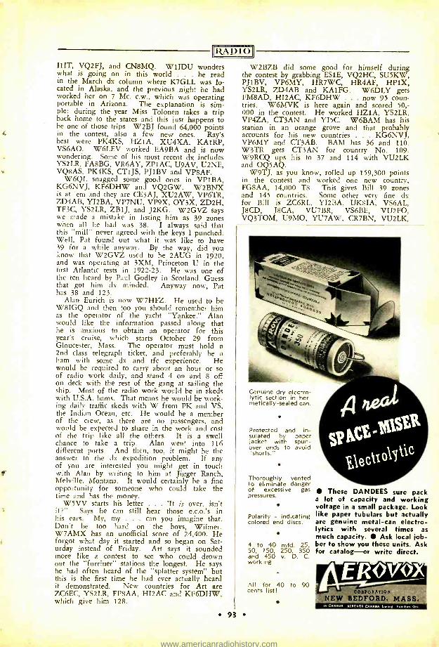
RADIO IIIT, VQ2FJ, and CN8MQ. W1IDU wonders what is going on in this world . he read in the March dx column where K7GLL was lo- cated in Alaska, and the previous night he had worked her on 7 Mc. c.w., which was operating portable in Arizona. The explanation is sim- ple: during the year Miss Tolonen takes a trip back home to the states and this just happens to be one of those trips. W2BJ found 64,000 points in the contest, also a few new ones. Ray's best were PK4KS, HZ1A, XU4XA, KA1RP, VS6AO. W6LEV worked EA9BA and is now wondering. Some of his most recent dx includes YS2LR, FA8BG, VR6AY, ZPIAC, U9AV, U2NE, VQ8AS, PK4KS, CT1JS, PJIBV and VP8AF.
W6QL snagged some good ones in VPIBA, KG6NVJ, KF6DHW and VQ2GW. W2BNX is at 'em and they are CE3AJ, XU2AW, VP6TR, ZD4AB, YI2BA, VP7NU, VP9X, OY3X, ZD2H, TF3C, YS2LR, ZB1J, and J2KG. W2GVZ says we made a mistake in listing him as 39 zones when all he had was 38. I always said that this "mill" never agreed with the keys I punched. Well, Pat found out what it was like to have 39 for a while anyway. By the way, did you know that W2GVZ used to be 2AUG in 1920, and was operating at 3XM, Princeton U in the first Atlantic tests in 1922 -23. He was one of the ten heard by Paul Godley in Scotland. Guess that got him dx minded. Anyway now, Pat has 38 and 123.
Alan Eurich is now W7HFZ. He used to be W8IGQ and then too you should remember him as the operator of the yacht "Yankee." Alan would like the information passed along that he is anxious to obtain an operator for this year's cruise, which starts October 29 from Gloucester, Mass. The operator must hold a 2nd class telegraph ticket, and preferably be a ham with some dx and tfc experience. He would be required to carry about an hour or so of radio work daily, and stand 4 on and 8 off on deck with the rest of the gang at sailing the ship. Most of the radio work would be in skeds with U.S.A. hams. That means he would be work- ing daily traffic skeds with W from PK and VS, the Indian Ocean, etc. He would be a member of the crew, as there are no passengers, and would be expected to share in the work and cost of the trip like all the others. It is a swell chance to take a trip. Alan went into 116 different ports. And then, too, it might be the answer to the dx expedition problem. If any of you are interested you might get in touch with Alan by writing to him at Jigger Ranch, Melville, Montana. It would certainly be a fine opportunity for someone who could take the time and has the money.
W5VV starts his letter . . . 'It is over, isn't it ?" Says he can still hear those e.c.o.'s in his ears. My, my . can you imagine that. Don't be too hard on the boys, Wilmer. W7AMX has an unofficial score of 24,400. He forgot what day it started and so began on Sat- urday instead of Friday. Art says it sounded more like a contest to see who could drown out the "furriner" stations the longest. He says he had often heard of the "splatter system" but this is the first time he had ever actually heard it demonstrated. New countries for Art are ZC6EC, YS2LR, FP8AA, HI2AC and KF6DHW, which give him 128.
W2BZB did some good for himself during the contest by grabbing ES1E, VQ2HC, SU5KW, PJIBV, VP6MY, HR7WC, HR4AF, HPIX, YS2LR, ZD4AB and KA1FG. W6DLY gets FM8AD, HI2AC, KF6DHW ... now 95 coun- tries. W6MVK is here again and scored 50,- 000 in the contest. He worked HZ1A, YS2LR, VP4ZA, CT3AN and YI5C. W6BAM has his station in an orange grove and that probably accounts for his new countries . KG6NVJ, VP6MY and CT3AB. BAM has 36 and 110. W3TR gets CT3AN for country No. 109. W9RCQ ups his to 37 and 114 with VU2LK and OQ5AQ.
W9TJ, as you know, rolled up 159,300 points in the contest and worked one new country, FG8AA, 14,000 T8. This gives Bill 39 zones and 145 countries. Some other very fine dx for Bill is ZC6RL, YI2BA, UK8IA, VS6AL, J8CD, J8CA, VU7BR, VS6BE, VU2FO, VQ3TOM, U9MO, YU7AW, CR7BN, VU2LK,
93
Genuine dry electro- lytic section in her- metically- sealed can.
Protected and in- sulated by paper jacket with spun - over ends to avoid "shorts."
Thoroughly vented to eliminate danger of excessive gas pressures.
Polarity - indicating colored end discs.
4 to 40 mfd. 25, 50, 150, 250, 350 and 450 v. D. C. working
All for 40 to 90 cents list!
These DANDEES sure pack a lot of capacity and working voltage in a small package. Look like paper tubulars but actually are genuine metal -can electro- lytics with several times as much capacity. Ask local job- ber to show you these units. Ask for catalog -or write direct.
CORPORATION
NEW BEDFORD, MASS. IN CANADA. ATROVOA CANADA L,,,,,.4 Nvma I,,. O,,,.
www.americanradiohistory.com
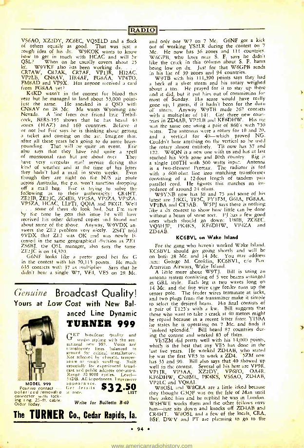
IRA DIO VS6AO, XZ2DY, ZC6EC, VQ5ELD and a flock of others equally as good. That was just a rough idea of his dx. W9KOK wants to know how to get in touch with HCAC and will he QSL? When on he usually covers about 25 kc. W9VKF also has been working dx. .
CR7AW, CR7AK, CR7AF, VP1JR, HI2AC, VP2LB, CN8AV, HR4AF, FG8AA, VP4TO, FM8AD and VP9X. Has anyone received a card from FG8AA yet?
K4KD wasn't in the contest for blood this year but he managed to land about 53,000 points just the same. He sneaked in a QSO with CN8AV on 28 Mc. Ma wants Wyoming and Nevada. A line from our friend Eric Trebil- cock, BERS -195 shows that he has heard 40 zones (HAZ) and 169 countries. Believe it or not but Eric says he is thinking about getting a ticket and coming on the air. Imagine that, after all these years he's going to do some brass - pounding. That will be quite an event. Eric also says that they have had quite a spell of monsoonal rain but are about over. They have very irregular mail service during this kind of weather and at the time of his letter they hadn't had a mail in seven weeks. Even though they are right on the N/S air route across Australia, the p.o. won't sanction dropping off a mail bag. Eric is trying to solve the following as to their authenticity: CR4HT, ZE2JB, ZE2JC, ZC4EB, VP2SA, VP2ZA, VP3ZA, VP5ZA, HCAC, LLFTI, QQIA and PKGI. Well
. some of them do look bad, but I'm sure by the time he gets this issue he will have received his other delayed copies and found out about some of the above. Anyway, W9VDX an- swers the ZE2 problem very nicely. ZS4T told 9VDX that ZE2 was OK and was newly li- censed in the same geographical division as ZE1. ZS6BJ, the QSL manager, also says the same. ZE2JC is on 14,320.
G6NF looks like a pretty good bet for G in the contest with his 70,115 points. He made 635 contacts with 37 as multiplier. Says that he didn't hear a single W7, VE4, VE5 on 28 Mc.
Genuine Broadcast Quality! Yours at Low Cost with New Bal-
anced Line Dynamic
TURNER 999
MODEL 999 Positive contact -
oolarized removable connector with lock- ing ring. 25 -ft. cable. Order today.
GET broadcast quality and studio styling with the sen-
sational new 999. Voice and transformer lines balanced to ground for critical installations. Not affected by climate, temper- ature or rough handling. Built especially for experienced broad- cast and public address operators. Range 30 -9000 cycles. Level - 54DB. All impedances. Impressive appearance.
$ 3 Get details at once.
2.510 ST
Write for Bulletin B -40
The TURNER Co., Cedar Rapids, la.
94
and only one W7 on 7 Mc. G6NF got a kick out of working YS2LR during the contest on 7
Mc. He now has 36 zones and 111 countries. W6GPB, who lives near S. F. says he didn't like the crack in this column about S. F. hams being low on dx. Just for that W6GPB sends in his list of 39 zones and 94 countries.
W9TB with his 111,390 points says they had a heck of a sleet storm and his rotary weighed about a ton. He prayed for it to stay up there and it did, but it put him out of commission for most of Sunday. His score would have really gone up, I guess, if it hadn't been for the durn of storm. Anyway W9TB made 267 contacts with a multiplier of 141. Got three new coun- tries in ZD4AB, VP2LB and KF6DHW. His rig was the same one using a pair of 860's with 750 watts. The antennas were a rotary for 10 and 20, and a vertical for 40 -which proved NG. Couldn't hear anything on the vertical so he used the rotary almost entitrely. TB now has 37 and 122. W4QN is a new one with us and has at last reached his 30th zone and 80th country. Rig is
a single 100TH with 300 watts input. Antenna is a two -element Premax. The radiator is fed with a 600 -ohm line into matching transformer consisting of a 12 -foot length of tandem pair parallel cord. He figures this matches an im- pedance of around 24 ohms.
W9YNB now has 30 and 75 and some of his latest are J2KG, TF5C, PY1FM, G6IA, FG8AA, VP1BA and CT3AB. W5PJ says there is nothing like a dx contest to show how little can be done without a beam of some sort. PJ has a few good ones which should go down: U8IB, ZC6EC, VQ3HJP, PK4KS, KF6DHW, VP4ZA and ZD4AB.
KC6BVL on Wake Island
For the gang who haven't worked Wake Island, KC6BVL should get going shortly and will be on both 28 Mc. and 14 Mc. You may address him: George M. Conklin, KC6BVL, c/o Pan -
American Airways, Wake Island. A little more about W9TJ. Bill is using an
antenna system consisting of 5 vee beams arranged in GRL style. Each leg is two waves long on 14 Mc. and the five wire cage feeder runs up the center pole. The feeder wires terminate at jacks, and two plugs from the transmitter make it simple to select the desired beam. His final consists of a pair of T125's with a kw. Bill suggests that those who want to take a crack at 40 meters might be repaid because in a recent letter from YI5BA he states he is operating on 7 Mc. and finds it "indeed splendid." Bill heard 87 countries dur- ing the contest and worked 85 of them.
VE5ZM did pretty well with his 14,000 points, which is the best that any VE5 has done in the last five years. He worked ZD4AB, who stated he was the first VE5 to work a ZD4. 5ZM now has 35 and 90. Bill also says that 40 showed up well in the contest. Several of his best are VP9R, VP1JR, VP3AA, XZ2DY, VP6FO, OA4R, KF6DHW, CN8ML, PK4KS, VS6AO, ZD4AB, VP2LC and VQ8AI.
W8OSL and W8CRA are a little irked because they thought G3QF was on the Isle of Man until they asked him and he replied he was in London. W8HWE works them and the other fellows envy him -just sits down and knocks off ZD4AB and CR4HT. W8OSL and a few of the locals, CRA, BSF, DWV and PT are planning to go to the
www.americanradiohistory.com
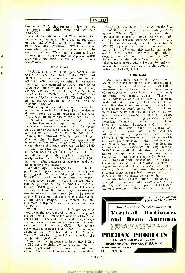
RADIO) Fair in N. Y. C. this summer. They want to visit some shacks while there -and get some ideas ? ? ??
VK3ZR has 30 zones and 72 countries after trying for a long time. He is gunning for Utah, Arizona and Nevada -wants to know if those states have any population. W9TB wants to know why everyone gets the urge to rebuild right after the contest. Wally has 38 zones and 125 countries now. W6KEV nabbed VQ2GW, which gave him a new zone, and VK9VG made him a new country.
More Phone
W9UYB goes to work and gets XZ2DX and ZE1JS for new zones and CT1AY, VP9R and HC2HP help to boost the countries to 40. W8QDU rolled up 28,000 points in the phone contest and only operated 40 hours. Fred added seven new phone countries: CN1AF, KF6DHW, VP7NS, VP1BA, PK1RI, HP1A, PK4KS. Now it's 26 and 61. W8NOH says that VO6T is on phone at 28,125 kc. while VP6YB and VP6MR are near the low edge of 10. Also VU2LO came in about 28,065 kc.
W4GY says it looks like we could use another W4 on phone so his list of 20 and 42 is welcome. He runs about 125 watts input most of the time. If you want to know how to work zone 15 just ask W6MLG. Doc had been waiting for two years for this zone to pop through . so he just chose a weekend to take a trip. Of course the 20 -meter phone band opened up and his "pal" W6FTU worked three or four stations in 15. Anyway, the following Monday night FTU got MLG on the "landline" and was razzing the deuce out of him for about an hour. The payoff is that during this hour W6NNR worked ES5D and had him standing by for W6MLG . but no, NNR couldn't get MLG because FTU had him all tied up on the telephone. Anyway, it finally worked out that MLG eventually raised him that night, after someone of authority broke up the telephone conversation.
W4DRZ says he managed to run up 62,000 points in the phone contest, which I'd say was pretty good. What a "dog fight" says Bud. W1HKK survived the phone contest and wound up with 60,000 points. K4DTH has just told us that he gathered in 176,778 points in the c.w. test and used 871/2 hours to do it. K4DTH wishes everyone to know that he will QSL to everyone that he worked in the contest but to be patient as it will be a rare job for him to make out all of the cards. Imagine 1406 contacts and the maximum multiplier of 42. Jose's best hour was 29 QSO's.
W6GRL did very nobly in both contests with 160,000 in the c.w. test and 110,000 in the phone portion. W6CUH made the most of his time and got 53,000. Charlie didn't know if he was to get any time to operate or not and no extensive plans were made. By the way, CUH is leaving the beach and has acquired a new "spot" in Burbank, which is about 15 miles north of Los Angeles. W6LYM looks like a good bet for his neck of the woods with 46,000 points.
You should be interested to know that HZ1A is OK but very definitely under cover. No use trying to get cards to him now . , but don't worry. You'll hear from him one of these days.
ZL2JQ, Johnny Shirley, is "sparks" on the S. S. City of Marseilles. He has been splashing around between Calcutta, Ceylon and London. Johnny says that he has been on the air nearly every night during slack periods working plenty of W's, and the whole world, too. He was signing XX2JQ and says that a lot of the boys called him all kinds of names, thinking he was another one of "those things." It's their tough luck be- cause he was working from around the Bay of Bengal and in the Indian Ocean. By the way, fellows, those of you who did work him and want to send him cards please do so under cover . . .
to his listed ZL2JQ QTH.
To the Gang
One thing I have been wanting to mention for sometime is that you fellows have been sending in a mighty fine bunch of letters . just full of interesting news and information. There are many of you who write a lot of things that are extremely interesting to me but never see print. This is due to the possibility of their not having a majority reader interest. I want you to know that I read every line that is written in to this department, and I enjoy everyone's letter. There are bound to be times when you may think something you send in should be printed, and it isn't. I assure you there is never anything personal in such omissions. Primarily this column is dx, and sec- ondly any comical, humorous and informative items that are received from the dx gang con- cerning the dx gang. We try to make the column as interesting as possible. Due to increase of work in this department it has been impossible to answer promptly many of the questions which you fellows have asked. I have been fortunate in securing the assistance of Guy Dennis, W6NNR, to handle the tabulating and statistical end of this department. Guy should need no in- troduction . he is an old timer (ex -6CR) .. .
and although on phone most of the time, he has a
key screwed to his desk. He knows dx from all angles, and should uphold the phone men's, shall we say, rights, in the future. He continually threatens to get on for a little brass -pounding, and if he does, fellows, please go easy on him.
The Marathon is sailing along in fine style and although some of you didn't quite make the 50 and 25, don't give up; the year isn't half over and your present standings will be kept on file.
BOOTH 830 AT THE N.R.T. SHOW, CHICAGO
See the latest Developments in
Vertical Radiators and Beni.. Antennas No matter what type of beam or array you pia n, you can build it better with l'remax Elements, Send for catalog and special prices.
PREMAX PRODUCTS DIV. CHISHOLM -RYDER CO.. INC.
HIGHLAND AVE., NIAGARA FALLS, N. Y.
SEND FOR TECHNICAL BULLETIN H -3
95
www.americanradiohistory.com
PARTS REQUIRED FOR BUILDING EQUIPMENT SHOWN IN THIS ISSUE
The parts listed are the components of the models built by the author or by "Radio's" Lab-
oratory staff. Other parts of equal merit and equivalent electrical characteristics usually may
be substituted without materially affecting the performance of the unit.
PERRINE ''XEC" Page 14
C,- Aerovox 484 C2, C,, C,- Aerovox 1450 Co, CÏ- Aerovox 1467 C,- Aerovox 284 G- Hammarlund MC100S Co- Hammarlund MEX Co-- Hammarlund HF35 C- Centralab special R,, 122, Ro, R3, R- I.R.C. type BT -1
R.- I.R.C. type C R,- Ohmite "Dividohm"
R,- Ohmite "Brown Devil" R33- I.R.C. type BT -Y2 R3, Roo, R - I.R.C. type BT -2
type F
S,- Centralab 2501 So, S- Centralab 2507 T,- Stancor P -4082 T2-Stancor P -4083 Ceramic sockets- Hammarlund type S
DAVIS 400 -WATT TRANSMITTER Page 28
C,- Cardwell XT- 220 -PS C., C:- Cardwell ZU- 100 -AS C,- Cardwell ET -30 -AD C Cardwell ER -50 -AD C -C -Solar XM -6 -22 R,, R2- Ohmite Carbohm R- Ohmite Brown Devil R3 -R- Ohmite Wirewatt R, R,, Roo- Ohmite Brown Devil RFC,, RFC_ Bud 920 RFC:, -Bud 568
AVERY and CONKLIN 56 -MC. RECEIVER Page 33
Co, C., C3- Hammarlund HF -15 C3, C3, C6, C7, C., C,,., Co, C,-Aerovox 1467 C8, Coo, CO3 C20, C.., C.,, C_;, C.,, C33- Aerovox 484 C.,- Aerovox PRS25 C13, C23, C30- Aerovox PBS450 C. Aerovox PRS50 C33-Hammarlund MEX R,, R2, R3-LR.C. BT-1/2 R,-I.R.C. BT-1 Ro-R,3-I.R.C. BT-1/2 R-Centralab 72-110 R,6 R33-I.R.C. BT-1/2 R.-Centralab 72-105 R22-Ohmite Brown Devil
REAL NEWS!
DYMAC RADIO Moves to New Quarters
1531 MAIN ST., AT FERRY
BUFFALO, N. Y.
W8RRL W8OLB W8QEE
R,o-R,-I.R.C. BT-1z R,.-R,,-I.R.C. BT-1 R:,,-Centralab 72-114 R-I.R.C. BT-1 R3o-R0-I.R.C. B7-1/2
T,-Stancor A-3840 T,-Stancor P-5057 CH-Stancor C-1002 Tubes-RCA
ADAMS PHONE SUPER
Page 41
C,, C1, CIO, C,_, C,o, C3. Go, Co,- Aerovox 484
C., C,, C3, C6, C;, C,, Co, C,:., C,33, C,- Aerovox 284
C,,, C.-Aerovox 1468 C.3,- Aerovox PR25
C.-Aerovox G450 C_,, C_.,, C.- Aerovox PBS450 CX, CZ- Hammarlund MEX CY- Hammarlund EC -80 R,, R,.,, R4, R, R,, R,, R,,,, R,,, R00, R.,, Centralab
514 R3, Roo- Centralab 516 R- Mallory -Yaxley G R,- Mallory- Yaxley Y5MP R,- Mallory -Yaxley N R_,- Mallory - Yaxley B -300 Truvolt T,- Meissner 16 -6643 T., T- Meissner 16 -6123 T3, T,- Meissner 17 -7458 T,- Meissner 16 -6645 T3-Meissner 17 -6869 X- Bliley CFI Tuning Unit Complete- Meissner 13 -7606
96
www.americanradiohistory.com
IIZADIOI
BEGINNER'S T21 TRANSMITTER Page 59
Transmitter C,, C6- Cardwell ZR -50 -AS
C3-Aerovox 1450 C7- Aerovox 684
R,- Centralab 516 R_, R3, R,- Ohmite Brown Devil RFC -Bud 920 X- Bliley LD2 Coil Forms -Hammarlund XP -53 Tube -Taylor T21
Power Supply T- Stancor P -6012 CH- Stancor C -1001 C- Cornell -Dubilier EH -9808 R- Ohmite Brown Devil
QRR Net The problem and solution of maintaining
communication in time of disaster is more and more falling into the hands of the radio amateur. Value of this type of communica- tion is rapidly being realized and its necessity is clearly pointed out with temporary failure of normal communication facilities.
Transportation of persons and supplies is a vital factor in the life of a community, a state or a nation in time of disaster or na- tional emergency, and communication neces- sary for uninterrupted operation is relatively equal in importance.
The Southern Pacific Company is submitting plans to the Federal Communication Commis- sion with the purpose of enlisting their sup- port and is also asking for volunteers from radio amateurs located along this company's lines to offer their assistance in emergencies.
In conjunction with this the Pacific Electric Railway Company, affiliated with the South- ern Pacific, is forming an emergency radio net to be coordinated with that of the South- ern Pacific to handle emergency traffic in the Southern California area.
W6OWC, supervising station and coordina- tor of the Southern California area, reports that already more than 150 radio amateurs in the western states have volunteered their serv- ices. However, the area surrounding Los An- geles is not properly covered, and all amateurs in this area desiring to volunteer or obtain further information relative to the activity of the emergency net are requested to communi- cate with Mr. W. F. Hibbard (W6OWC), Engineering Department, Pacific Electric Rail- way Company, 610 South Main Street, Los Angeles, California.
In writing please furnish the following in- formation: Name, post office address, tele- phone number, station call, whether your station is operated on phone or c.w., fre- quencies on which your station is operated, and times you could be available for service.
kiuvAtaistf 901.cie/z Aerovox Corporation Allied Radio Corp. American Microphone Co., Inc Bliley Electric Co. 79 Bud Radio, Inc. 77 Burstein -Applebee Co. 78 Cannon Company, C. F. 72 Cardwell Manufacturing Co., The Allen D. 83 Centralab 73 Cornell -Dubilier Electric Corporation 74 Dymac Radio 96 Eitel- McCullough, Inc. Cover II Guardian Electric 81 Guthman & Co., Edwin I. 91 Hammarlund Manufacturing Co., Inc. 3
Harrison Radio Co. 89 Heintz & Kaufman, Ltd. 75 Henry Radio Shop 86 Kaar Engineering Co. 90 Mallory & Co., Inc., P. R. 71 Meissner Manufacturing Co. 7
Ohmite Manufacturing Co. 76 Premax Products 95 Radio Amateur Call Book 88 RADIO Antenna Handbook Cover III RADIO Handbook 69 RADIO Noise Reduction Handbook . . Cover III RADIO TECHNICAL DIGEST 80 RADIO WAZ Map 97 RCA Manufacturing Co. Cover IV Radio Supply Co. 79 Radio -Television Supply Co. 87 Solar Manufacturing Co. 82 Taylor Tubes, Inc. 5
Turner Co., The 94 Ward Leonard Electric Co. 89
93 85 84
"W. A. 7Lo99 MAP Size 24" x 28"
Heavy White Paper Now is the time to order your copy of this famous map! The W.A.Z. plan is the best "yard- stick" yet developed for the measurement of DX achievement.
A Map Of The World For Only 25c
postpaid, anywhere Canadian postal notes (25c) accepted. Five international postal reply coupons accepted as 25c.
RADIO, Ltd. 7460 Beverly Blvd, Los Angeles
97
www.americanradiohistory.com
/lilil,,T4iie'tplace
(a) Commercial rate 10c per word, cash with order; minimum, $1.00. Capitals: 13c per word. For consecutive advertising, 15% discount for 3d, 4th, and 5th insertions; 25% thereafter. Break in continuity restores full rate. Copy may be changed as often as
desired. (b) Non -commercial rate: 5c per word,
cash with order; minimum, 50c. Available only to licensed amateurs not trading for profit; our judgment as to character of ad- vertisement must be accepted as final.
)c) Closing date (for classified forms only): 25th of month; e.g., forms for March issue, published in February, close January 25th.
Id) No display permitted except capitals. le) Used, reclaimed, defective, surplus,
and like material must be so described. (f) Ads not relating to radio or radiomen
are acceptable but will be grouped separately. (g) No commissions nor further discounts
allowed. No proofs, free copies, nor reprints sent.
(h) Send all Marketplace ads direct to Los Angeles accompanied by remittance in full payable to the order of Radio, Ltd.
SERVICEMEN, DEALERS: Boost business with advertising car- toons, ideas, Catalogue 10c. Radiolabs, Winnipeg.
LISTEN for High Frequency Broadcast Station, W9XA, 26,450 kilocycles, Kansas City, Missouri.
AMATEUR RADIO LICENSES. COMPLETE TRAINING IN CODE AND THEORY. DAY AND EVENING CLASSES IN NEW YORK. ALSO HOME STUDY COURSES. HUNDREDS OF LICENSED STUDENTS ON THE AIR. AMERICAN RADIO INSTITUTE. 1123 BROADWAY, NEW YORK.
RECONDITIONED guaranteed receivers. Practically all models cheap. Shipped on ten day trial. Terms. List free. W9ARA. Butler, Missouri.
CONSOLIDATED Official Radio Service Manual from 1923 to 1934. Goad condition, $10.00 plus postage or crystal micro- phone or phonograph pick -up. W1ITQ, 24 Martin St., Warren, R. I.
REFRIGIDAREA Refrigeration Service Manual. Trouble preven- tion, diagnosis, repairs. $1.50. Barnes' 1627 N. Ehlgen, Tulsa, Oklahoma.
FBXA, formerly W6GRL's $20.00; 1 Bi -push complete with power supply $50.00; 1 Leeds Noise Silencer $4.00; 1 used HK 354 $12.00; 1 5V, 20A Fila. transformer $4.50; 1 Crittenden 866 Bridge Fila. transformer 10,000 volt insulation $4.50. A. H.
Stovall, Jr. W6FET, 4220 McFarlane Ave. Burbank. Call Charleston 6 -6337.
CRYSTALS AIRMAILED: June only 40X $1.50, 20 meter crystals with holders $3.95. COMMERCIAL crystals quoted. C -W Man- ufacturing Co. 1170 Esperanza, Las Angeles.
CRYSTALS IN PLUG -IN HEAT DISSIPATING HOLDERS 160 -80 $1.25 (No Y cuts) 40X $1.60. Pacific Laboratories 344 Fet- terly, Los Angeles.
FREE -to the writer of a letter giving the hest reasons for wanting it: one copy of Henney's RADIO ENGINEERING HAND- BOOK (First edition, third imp.), in good condition, postpaid. W. E. McNatt, 45 Lackawanna Ave., East Stroudsburg, Pa.
Classified Advertising
BRAND new, guaranteed, Radio tubes 25c each, details: Box 37, Station P, Brooklyn, New York.
DOUGLAS universal modulation transformers match all tubes. The
best price, quality and service obtainable anywhere. 50 watts audio $4.95 pair. 100 watts audio $7.75 pair. Postpaid. One
year guarantee. Write W9IXR, Rice Lake, Wisconsin.
MASONITE panels. Baked gray wrinkle finish. R. H. Lynch, 970 Camulos, Los Angeles, California.
SELL or TRADE: Dodge generator 110 volts AC 800 watts $12.00; Carter 425A Genemotor 6/400 volts 200 mills $15.00; Carter 420A- 12/400 volts 200 mills $15.00; Both like new; Meters tubes, etc. send stamp for list. W5CHG, Happy, Texas.
FOR SALE: One new 100 watt bandswitching plate modulated phone with T -21 and TZ -20 tubes. Has AMC and xtal mike input on speech. 160, 75, 20 and 10 meter bands with 160 or SO meter xtals. Mounted in grey crackle and silver finished cabinet 34 inches high. Complete with built-in four band
coils and tubes for $140.00. Frank C. Jones, 2037 Durant Ave. Berkeley, California.
FOR SALE: One new model 250 watt phone with AMC. Mounted in 3 feet grey cabinet. Xtal mike input, T240 modulator. HK240 and HK254 in rf. Coils for 75, 20 and 10 meter bands. Complete with tubes and microphone for $225.00. Frank C. Jones, 2037 Durant Ave., Berkeley, California.
WANTED: certain issues of Vol. 1 of "CO" (later known as
"Commercial Radio "). Please state condition and price. R. S.
Ould, 3747 Huntington St., Washington, D. C.
ANY radia circuit diagram 25c. Order mentioning manufacturer's name, model. Catalog free. Supreme Publications, 3727 West Thirteenth, Chicago.
QSL'S -HIGHEST QUALITY -LOWEST PRICES. RADIO HEAD- QUARTERS, FORT WAYNE, INDIANA.
IT'S THE AUTHORITY .
Take "Radio" Every Issue RADIO, Ltd., Technical Publishers 7460 Beverly Blvd. Los Angeles, California
Send RADIO for one two a years, 4? 00
.501 J foreign rates* see page f page 4.
five issues, $1.00 for new subscribers in U.S.A. and Canada* only.
Also include "RADIO HANDBOOK ($1.50 in continental U.S.A.; elsewhere* $1.65 or 7s.1
"RADIO" ANTENNA HANDBOOK (75c in con- tinental U.S.A.; elsewhere *, 85c or 3s. 6d.1
"RADIO TECHNICAL DIGEST ", 2 years 12.50 in U.S.A., Canada *, Pan American countries *, elsewhere *, $3.00 or 12s. 6d.1
Name Call
Address
City Remittances must be payable at par In continental
U.B.A. Add 10e to Canadian checks. Canadian postal nobs; accepted. _
Code: 240
98 PRINTED AT PLANT OP HUGHES PRINTING CO. EAST STROUDSBURG, PA.
www.americanradiohistory.com
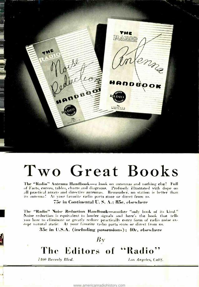
Two Great Books The "Radio" Antenna Handbook -a book on antennas and nothing else! Full of Facts, curves, tables, charts and diagrams. Profusely illustrated with dope on all practical arrays and directive antennas. Remember, no station is better than its antenna! At your favorite radio parts store or direct from us.
75c in Continental U. S. A.; 85c, elsewhere
The "Radio" Noise Reduction Handbook -another "only book of its kind." Noise reduction is equivalent to louder signals and here's the book that tells You how to eliminate or greatly reduce practically every form of radio noise ex- cept natural static. At your favorite radio parts store or direct from us.
35c in U.S.A. (including possessions) ; 40e, elsewhere
By
The Editors of "Radio" 460 Beverly Blvd. Los Angeles, Calif.
www.americanradiohistory.com
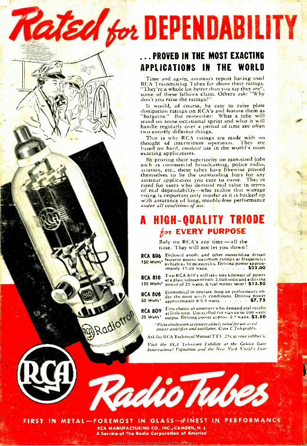
!f!4'41'1t DEPENDABILITY ... PROVED IN THE MOST EXACTING
APPLICATIONS IN THE WORLD Time and again, amateurs report having used
RCA Transmitting Tubes far above their ratings. "They're a whole lot better than you say they are ", some of these fellows claim. Others ask: "Why don't you raise the ratings ?"
It would, of course, be easy to raise plate dissipation ratings on RCA's and feature them as "bargains." But remember: What a tube will stand on some occasional sprint and what it will handle regularly over a period of time are often two entirely different things.
That is why RCA ratings are made with no thought of intermittent operation. They are based on hard, constant use in the world's most exacting applications.
By proving their superiority on man -sized jobs such as commercial broadcasting, police radio, aviation, etc., these tubes have likewise proved themselves to be the outstanding buys for any amateur application you care to name. They're rated for users who demand real value in terms of real dependability -who realize that wattage rating is important only insofar as it is backed up with assurance of long, trouble -free performance under all conditions of use.
A HIGH - QOALITY TRIODE got EVERY PURPOSE Rely on RCA's any time -all the time. They will not let you down !
RCA 806 Enclosed anode and other outstanding design
150 Watts* features assure maximum ratings a frequencies as high as 30 megacycles. Driving power approx- imately 15 -20 watts 02.00
RCA 810 Two RCA 's ill take kilowatt of power at a plate vol810tage
w of only 2,000
one volts and a driving
125 Watts* power of 25 watts. A real money saver! $ 13.50
RCA 808 Economical to operate, long on performance un- der the most severe conditions. Driving power
50 Watts* approximately 8 -9.5 watts $7 73
RCA 809 First choice of amateurs who demand real results at little cost. Unexcelled for rigs up to 100 watts
25 Watts* output. Driving power approx. 2.5 watts. $2.50 *Plate dissipation as conservatively rated for use as r 1 power amplifier and oscillator, Class C Telegraphy.
Ask for RCA Technical Manual TT3. 25c at your jobber's.
Visit the RCA Television Exhibits at the Golden Gate
International Exposition and the New York lf'orld's Fair
FIRST IN METAL -FOREMOST IN GLASS- FINEST IN PERFORMANCE RCA MANUFACTURING CO., INC., CAMDEN, N. J.
A Service of The Radio Corporation of America
www.americanradiohistory.com