with optional baffle dif 630 - wordentec limited · operating manual incl. manufacturer’s...
TRANSCRIPT

Operating manualIncl. Manufacturer’s declaration
BP 803 079 BE (9803) 1
Diffusion pumpwith optional baffle
DIF 630

2 BP 803 079 BE (9803) DIF630.om
In all communications with Balzers, please specify the information given on theproduct nameplate. For convenient reference transfer this information into thediagram below.
Typ: DIF 630No: BP D09 508F-No:
V HzkW
This document applies to products with part number
BP D09 508
The part number can be taken from the product nameplate.
We reserve the right to make technical changes without prior notice.
Diffusion pumps are used for generating high vacuum.
Product identification
Validity
Intended use

BP 803 079 BE (9803) DIF630.om 3
Table of contents
Product identification 2Validity 2Intended use 2
1 Description 41.1 Overview 41.2 Function 51.3 Using a diffusion pump in a pumping station 5
2 Safety 62.1 Symbols used 62.2 Personnel qualifications 62.3 Safety information 72.4 Liability and warranty 7
3 Technical data 8
4 Installation 104.1 Removing the transport safety device 114.2 Installing the cold cap 124.3 Filling the pump fluid 164.4 Vacuum connection 184.5 Cooling water connection 204.6 Power connection 224.7 Mounting the thermostatic cut-out 264.8 Mounting the thermal switch 26
5 Initial start up 27
6 Operation 28
7 Deinstallation 307.1 Power connection 317.2 Cooling water connection 337.3 Vacuum connection 337.4 Deinstalling the cold cap 347.5 Draining the pump fluid 36
8 Troubleshooting 398.1 Resetting the thermostatic cut-out (option) 39
9 Maintenance / Repair 409.1 Checking the pump fluid level 419.2 Replenishing the pump fluid 419.3 Cleaning the diffusion pump, replacing the jet system 429.4 Replacing a heating plate 45
10 Options 5210.1 Cooling water flow monitor 5210.2 Thermostatic cut-out 5210.3 Thermal switch 5310.4 Baffle 5310.5 Pump fluid replenishing device 5410.6 Protective screen 54
11 Consumables 5511.1 Pump fluid 55
12 Spare parts 5612.1 Seals 5612.2 Heating plate 5712.3 Heater contact paste 5712.4 Jet system 57
13 Returning the product 58
14 Disposal 58
Declaration of Contamination 59
Manufacturer’s declaration 60

4 BP 803 079 BE (9803) DIF630.om
1 Description
High vacuum connection
Sight glass for checkingthe pump fluid level
Cooling water connectionsfor cold cap
Mounting base forthermostatic cut-out
Cooling water connectionfor housing (feeder line)
Terminal box
Mounting base for temperature switch
Connection for pump fluidreplenishing device (option)
Housing
Connection for pump fluidtemperature measurement(only for special application)
Cooling water circuit forcold cap
Cooling water circuitfor housing
Fore vacuum connection
Welded nuts for supportingthe diffusion pump
Cooling water connectionfor housing (return line)
Jet systemaccelerating andguiding the pumpfluid vapor
Fore vacuum bafflereducing the pumpfluid consumption athigh gas throughput
Heater for heatingthe pump fluid
Cold cap reducingpump fluid back-streaming from thediffusion pump intothe vacuum chamber
The thermostatic cut-out (option) prevents overheating of the diffusion pump.
The thermal switch (option) is used in conjunction with a pumping station control. Itsignals to the pumping station control that the pump has attained normal operatingtemperature. Depending on the pump fluid the operating temperature on themounting base is between 150 °C and 180 °C.
1.1 Overview
Thermostatic cut-out
Thermal switch

BP 803 079 BE (9803) DIF630.om 5
Flow direction of thegas molecules
The pump fluid vaporstream is acceleratedby the jet system anddirected toward thecooled housing at aspecific angle
The heater heats thepump fluid in thevaporating chamberup to the evaporationpoint
The pump fluid condensesat the cooled housing walland flows as a thin oil filmback to the evaporatingchamber
Evaporating chamber
Purification zone
The fore vacuum pressure ensures that the pump fluid vapor stream spreadswithin the diffusion pump.
Gas molecules from the high vacuum flange area that enter the pump fluid streamreceive an impulse in the direction of the vapor stream which results in a pumpeffect.
In the process gas molecules can diffuse into the pump fluid. When flowing backto the evaporating chamber the pump fluid passes through a zone of elevatedtemperature, the purification zone, so that light contamination and the pumped outgases are separated from the pump fluid by a temperature increase and are alsoconducted to the roughing pump.
Example of a vacuum diagram:
Vacuum chamber
Bypass valve
Fore vacuumgauge
High vacuumgauge
High vacuum valve
Diffusion pump
Fore vacuum valve
Roughing pump
Fore vacuumgauge
Bypass line
Fore vacuum gauge
Baffle
Vent valve
1.2 Function
Pump fluid circuit
Pumping principle
1.3 Using a diffusion pumpin a pumping station

6 BP 803 079 BE (9803) DIF630.om
2 Safety
DANGER
Information on preventing any kind of physical injury .
WARNING
Information on preventing extensive equipment and environmental damage.
Note
Information on correct handling or use. Disregard can lead to malfunctions orminor equipment damage.
6.1 Dimensions in mm
→ 2 See page ...
Skilled personnel
All work described in this document may only be carried out by persons whohave suitable technical training and the necessary experience or who have beeninstructed by the custodian of the product.
2.1 Symbols used
2.2 Personnel qualifications

BP 803 079 BE (9803) DIF630.om 7
• Adhere to the applicable regulations and take the necessary precautions forthe process media used.
Consider possible reactions between the materials ( → 2 8) and the processmedia.
Consider possible reactions of the process media due to the heat generated bythe product.
• Adhere to the applicable regulations and take the necessary precautions for allwork you are going to do and consider the safety information in this document.
• Before you begin to work, find out whether any vacuum components are con -taminated. Adhere to the relevant regulations and take the necessary pre -cautions when handling contaminated parts.
Pass on the safety information to other users.
Balzers assumes no liability and the warranty becomes null and void if the custo -dian or third parties
• disregard the information in this document
• use the product in a non-conforming manner
• make any kind of changes (modifications, alterations etc.) to the product
• use the product with accessories not listed in the corresponding productdocumentation.
The custodian assumes the responsibility in conjunction with the process mediaused.
2.3 Safety information
2.4 Liability and warranty

8 BP 803 079 BE (9803) DIF630.om
3 Technical data
Diffusion pump DIF 630
High vacuum flangeClamping flange DN 630 ISO-K
Fore vacuum flangeClamping flange DN 160 ISO-K
Line voltageFrequency
3×400 / 3×230 VAC50 Hz
Power consumption 10.5 kW (7×1.5 kW)
Pumping speed for air 1) at 1×10⁻⁴ mbar 15,000 l/s
Pumping speed for air 1) at 1×10⁻² mbar 18 mbar l/s
Working range 10-7 ... 1×10⁻² mbar
Fore vacuum stability 0.5 mbar
Pump fluid filling capacityminimumoptimummaximum
6000 cm3
7000 cm3
8000 cm3
Pump fluid consumption 7.5×10⁻⁵ g/mbar l
Recommended pumping speed of theroughing pump 2) for an operating pressure 3)
above 10-4 mbarbelow 10-4 mbar
240 ... 1000 m3/h170 ... 240 m3/h
Heating time 50 min.
Cooling time 90 min.
Cooling water requirements → 2 20
MaterialsHousingJet system
SteelAl
Weight 250 kg
1) Values measured with synthetic oil 71 A according to Pneurop or DIN 28427.2) Two-stage rotary vane pumps or pump combinations of one- or two-stage rotary vane
pumps and roots pumps are recommended as roughing pumps.3) In continuous operation.
Vacuum connection
Power input
Characteristics
Pump fluid
Roughing pump
General

BP 803 079 BE (9803) DIF630.om 9
DN 160 ISO-K
ø 690
1121
526
500
DN 630 ISO-K
M20
3 × 120°
High vacuum connection
Fore vacuum connection
Power connection
Cooling water connection ø13 mm
Sight glass
Dimensions

10 BP 803 079 BE (9803) DIF630.om
4 Installation
DANGER
Caution: damaged product
Putting a damaged product into operation can be extremely danger -ous.
Do not install the product if there is any visible damage.
220 °C
DANGER
Caution: hot surface
In operation the diffusion pump is heated up to 220 °C. Touching thelower housing section can cause burns.
Install the diffusion pump in such a way that inadvertent contact withthe pump is not possible (protective screen available on request).
250 kg
DANGER
Caution: heavy product (250 kg)
Physical injury can result if the product is lifted and transported byonly one person.
The product must be lifted and transported in accordance with therules and guidelines applicable in the country of installation.
WARNING
Caution: fire hazard
Due to the thermal radiation of the heater, parts in close proximity canignite.
If there is less than 150 mm of clearance between the bottom of thehousing and the base plate, thermal insulation pads must be installed.
>15
0 m
m
Visual check
Protective screen
Transport
Thermal radiation

BP 803 079 BE (9803) DIF630.om 11
Note
Caution: vacuum component
Dirt and damages impair the function of the vacuum component.
When handling vacuum components, take appropriate measures toensure cleanliness and prevent damages.
Note
Caution: dirt sensitive area
Dirt prolongs the pumpdown process.
Always wear clean, lint-free gloves and use clean tools when workingin this area.
Note
Keep the protective cover and cap and put them in place again whenthe product is removed from the vacuum system.
Note
Keep the transport safety device and put it in place again when theproduct is transported.
Remove the transport safety device as well as the protective cover and cap.
4.1 Removing the transportsafety device
Protective cover and cap
Transport safety device
Procedure

12 BP 803 079 BE (9803) DIF630.om
Note
Caution: vacuum component
Dirt and damages impair the function of the vacuum component.
When handling vacuum components, take appropriate measures toensure cleanliness and prevent damages.
Note
Caution: dirt sensitive area
Dirt prolongs the pumpdown process.
Always wear clan, lint-free gloves and use clean tools when working inthis area.
è Unscrew the centering pin.
4.2 Installing the cold cap
Procedure

BP 803 079 BE (9803) DIF630.om 13
� Mount the cold cap.
Washer
Hexagon socket screwM6 × 16
O-ring, FPM (Viton), ø20.2 × 2.6
Size 5
� Mount the cooling tube.
Counterhold.
Washer
Nut

14 BP 803 079 BE (9803) DIF630.om
� Screw in the centering pin until the mechanical stop is reached.
� Check the position of the cold cap and adjust it if necessary.
Upper surfaceof the cold cap
Centering pin
The centering pin must beflush with the upper surfaceof the cold cap.
Untighten the nutif necessary andadjust the positionof the cold cap.

BP 803 079 BE (9803) DIF630.om 15
ò Mount the elbow.
Seal thethread.
ó Mount the hose nozzle.
Seal
Union nut
Hose nozzle ø13

16 BP 803 079 BE (9803) DIF630.om
Note
Caution: vacuum component
Dirt and damages impair the function of the vacuum component.
When handling vacuum components, take appropriate measures toensure cleanliness and prevent damages.
Note
Caution: dirt sensitive area
Dirt prolongs the pumpdown process.
Always wear clan, lint-free gloves and use clean tools when working inthis area.
As the diffusion pump is supplied in cleaned condition, any of the pump fluidslisted below can be chosen.
The diffusion pump must be cleaned whenever the pump fluid is changed(→ 2 42).
The choice of pump fluid depends on the vacuum engineering application. Thetable below lists some of the relevant selection criteria.
Mineral oil Synthetic oil Silicone oil Pentaphenylether
61 A 71 A DC 704 AN 175 Santovac 5
Preferred vacuum range 5×10⁻⁶ ... 10-2
mbar5×10-7 ... 10-3
mbar10-7 ...10-3
mbar10-8 ...10-5
mbar10-8 ... 10-3
mbar
Resistance to chemicals good good superior superior excellent
Resistance to oxidation good good superior superior excellent
Resistance to thermaldecomposition good good superior superior excellent
Theor. vapor pressure at 20° C 5×10⁻⁷ mbar 2×10⁻⁸ mbar 2×10⁻⁸ mbar 4×10⁻¹⁰ mbar 1×10⁻¹⁰ mbar
Additional information can be found in the catalog. Ordering numbers → 2 55.
4.3 Filling the pump fluid
Pump fluid
Pump fluid change
Selection criteria

BP 803 079 BE (9803) DIF630.om 17
Fill in the pump fluid through the fore vacuum port until the optimum pump fluidlevel is attained.
Note
Make sure the diffusion pump is positioned upright when you fill in thefluid.
The pump fluid spreads only slowly within the diffusion pump. For thisreason the actual pump fluid level can be read only after ≈ 3 min.
maximum 8000 cm3
optimum 7000 cm3
minimum 6000 cm3
Pump fluid filling capacities:
Filling

18 BP 803 079 BE (9803) DIF630.om
Note
Caution: vacuum component
Dirt and damages impair the function of the vacuum component.
When handling vacuum components, take appropriate measures toensure cleanliness and prevent damages.
Note
Caution: dirt sensitive area
Dirt prolongs the pumpdown process.
Always wear clean, lint-free gloves and use clean tools when workingin this area.
The diffusion must be installed perpendicularly. We recommend to support thediffusion pump using the welded nuts (e.g. screwing in M20 threaded rods andswiveling pressure disks).
(M20) threaded rod
Swiveling pressure disk
4.4 Vacuum connection
Mounting plane

BP 803 079 BE (9803) DIF630.om 19
The high vacuum connection is established via a DN 630 ISO-K clamping flange.
12 clamps:ordering numberBP 226 877 -T(1 set of 4 clamps)
O-ringFPM (Viton)AN 475ø 658.9 × 7(included)
DN 630 ISO-K
Wrench size 19
Additional information can be found in the catalog.
The fore vacuum connection is established via a DN 160 ISO-K clamping flange.
4 clamps:ordering numberBP 226 875 -T(1 set of 4 clamps)
O-ringFPM (Viton)AN 362ø 158.1 × 5.3(included)
DN 160 ISO-K
Wrench size 17
Additional information can be found in the catalog.
4.4.1 High vacuum connection
4.4.2 Fore vacuum connection

20 BP 803 079 BE (9803) DIF630.om
To achieve optimum cooling of the diffusion pump the following parameters arerelevant:
• Required cooling water pressure in the feeder line
• Cooling water temperature in the return line
The diffusion pump has two separate cooling water circuits:
≤ 30°C
≤ 30°C
Return lineconnection
Feeder lineconnection
Cooling water circuitfor cold cap
Cooling water circuitfor housing
As the cooling water temperature in the return line can only be determined duringoperation we recommend a presetting based on the following diagram:
24 °C 20 °C 12 °C 1 2 [bar]
200
600
400
0
[l/h]
0
300
3 4 5
8001000
Cooling water temperaturein feeder line [°C]
∆p pressure drop incooling water circuit
Minimum waterrequirements with acooling water tem-perature of ≤ 30 °Cin the return line
Note
Be aware of the pressure drop in the feeder and return lines of thecooling water circuits.
According to document BB 800 851 BN
4.5 Cooling waterconnection
Cooling water circuits
Minimum cooling waterrequirements for the housingcircuit
Pressure drop in the feeder andreturn lines
Cooling water specifications

BP 803 079 BE (9803) DIF630.om 21
Shut-off valves must be installed in the feeder lines and flow monitors should beprovided for the return lines in order for the diffusion pump heater to switch offwhen the cooling water flow is too low.
Note
Make sure the cooling water hoses do not touch the housing.
Return line
Shut-off valve
Feeder lineReturn line
Flow monitor(option)
Shut-off valve
Flow monitor(option)
Feeder line Cooling watercircuit for housingCooling watercircuit for cold cap
For operation with Santovac 5, the cooling of the purification area must be by -passed. For doing so, the short tube must be removed.
Shut-off valve Return line
Feeder lineReturn line
Feeder line Cooling watercircuit for housingCooling watercircuit for cold cap
Shut-off valve
Flow monitor(option)
Flow monitor(option)
Connection
Operation with Santovac 5

22 BP 803 079 BE (9803) DIF630.om
The power connection is established via the terminals in the terminal box. Beforeconnection make sure that your local line voltage agrees with the ratings on thename plate (→ 2 2). If your line voltage differs please contact your nearest BalzersService Center.
Skilled personnel
The power connection may only be established by a skilled electri -cian.
è Open the terminal box.
8 910
1112
1314
L1L2
L3N
1 23 4
5 67
4.6 Power connection
Personnel qualifications
Procedure

BP 803 079 BE (9803) DIF630.om 23
� Depending on the line voltage (3×400 VAC / 3×230 VAC) the jumper wiresmust be connected.
8 910
1112
1314
L1L2
L3N
1 23 4
5 6 7
L2 L3L1 N PE
1
8
2
9
3
10
4
11
5
12
6
13
7
14
Wire cross-section 6 mm2
1.5
kW
1.5
kW
1.5
kW
1.5
kW
1.5
kW
1.5
kW
1.5
kW
8 910
1112
1314
L1L2
L3N
1 23 4
56 7
L2 L3L1
1
8
2
9
3
10
4
11
5
12
6
13
7
14
PE
Wire cross-section 6 mm2
1.5
kW
1.5
kW
1.5
kW
1.5
kW
1.5
kW
1.5
kW
1.5
kW
3×400 VACstar connection(factory setting)
3×230 VACdelta connection
24 BP 803 079 BE (9803) DIF630.om
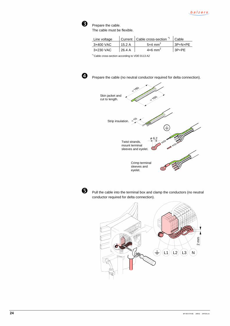
� Prepare the cable.The cable must be flexible.
Line voltage Current Cable cross-section *) Cable
3×400 VAC 15.2 A 5×4 mm2 3P+N+PE
3×230 VAC 26.4 A 4×6 mm2 3P+PE*) Cable cross-section according to VDE 0113 A2
� Prepare the cable (no neutral conductor required for delta connection).
ø 6,2
Strip insulation.
Skin jacket andcut to length.
Crimp terminalsleeves andeyelet.
Twist strands,mount terminalsleeves and eyelet.
� Pull the cable into the terminal box and clamp the conductors (no neutralconductor required for delta connection).
8 910
1112
1314
L1L2
L3N
1 23
45 6
7
L1L2
L3N
1 23 4
5 6 7
L1 L2 L3 N
2 m
m

BP 803 079 BE (9803) DIF630.om 25
ò Tighten the cable gland.
ó Tighten the cable strain relief.
õ Close the terminal box.
89
1011
1213
14
L1L2
L3N
12
3 45
6 7
ö Connect the power cable to the control system.
Note
Install the power cable in accordance with the national regula -tions. Make sure that the power lead does not touch the hous -ing.

26 BP 803 079 BE (9803) DIF630.om
The thermostatic cut-out is fastened to the mounting base with two M4 screws.
39
M4
Thermostatic cut-out(option)
The thermal switch is fastened to the mounting base with two M4 screws.
M4 27
Thermal switch(option)
4.7 Mounting the thermo-static cut-out
4.8 Mounting the thermalswitch

BP 803 079 BE (9803) DIF630.om 27
5 Initial start up
• Diffusion pump installed (→ 2 10).
• Thermostatic cut-out connected to the pumping station control.
• Thermal switch connected to the pumping station control.
• Pumping station ready for operation.
mbar
0.1
≤ 30°C
°C
+–
First timeoperation
Check the pump fluid level (→ 2 41).è
ó
ò
�
�
�
�
Start the water coolings (open the shut-off valves).
Start the heater.
Wait for the pump to heat up (50 min.).Depending on the pump fluid, the pump heats up toan operating temperature of 150 °C ... 180 °C on themounting base of the thermal switch.
Set the thermal switch (option) in accordance with theseparate instructions.
Diffusion pumpready for use
Pump down the vacuum system to ≤ 0.1 m bar.
Check the cooling water temperature in the return lines. Increase the cooling water flow if the cooling watertemperature in either return line exceeds 30 °C.
Preconditions
Procedure

28 BP 803 079 BE (9803) DIF630.om
6 Operation
°C
220 °C
DANGER
Caution: hot surface
Touching the hot surface (≈ 220 °C) can cause burns.
Wear protective gloves.
WARNING
Caution: fire hazard
Easily ignitable materials near the diffusion pump can catch fire.
Do not store any easily ignitable material near the diffusion pump.
WARNING
Caution: fire hazard
Hot pump fluid can ignite under atmospheric conditions.
Never expose hot pump fluid to atmospheric pressure, that is, thediffusion pump must not be vented during operation.
Example of a vacuum diagram:
Vacuum chamber
Bypass valve
Fore vacuumgauge
High vacuumgauge
High vacuum valve
Diffusion pump
Fore vacuum valve
Roughing pump
Fore vacuumgauge
Bypass line
Fore vacuumgauge
Baffle
Vent valve
Overview
BP 803 079 BE (9803) DIF630.om 29
mbar
0.1
Switch on
Diffusion pumpready for use
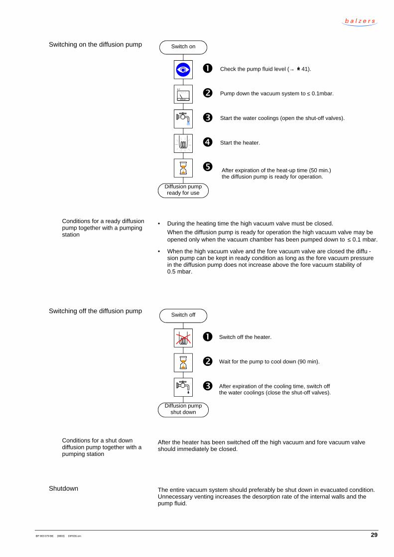
Check the pump fluid level (→ 2 41).è
�
�
�
�
Start the water coolings (open the shut-off valves).
Start the heater.
After expiration of the heat-up time (50 min.)the diffusion pump is ready for operation.
Pump down the vacuum system to ≤ 0.1mbar.
• During the heating time the high vacuum valve must be closed.
When the diffusion pump is ready for operation the high vacuum valve may beopened only when the vacuum chamber has been pumped down to ≤ 0.1 mbar.
• When the high vacuum valve and the fore vacuum valve are closed the diffu -sion pump can be kept in ready condition as long as the fore vacuum pressurein the diffusion pump does not increase above the fore vacuum stability of0.5 mbar.
Diffusion pumpshut down
Switch off
Switch off the heater.è
�
� Wait for the pump to cool down (90 min).
After expiration of the cooling time, switch offthe water coolings (close the shut-off valves).
After the heater has been switched off the high vacuum and fore vacuum valveshould immediately be closed.
The entire vacuum system should preferably be shut down in evacuated condition.Unnecessary venting increases the desorption rate of the internal walls and thepump fluid.
Switching on the diffusion pump
Conditions for a ready diffusionpump together with a pumpingstation
Switching off the diffusion pump
Conditions for a shut downdiffusion pump together with apumping station
Shutdown

30 BP 803 079 BE (9803) DIF630.om
7 Deinstallation
DANGER
Caution: contaminated parts
Contaminated parts can be detrimental to health.
Before you begin to work, find out whether any parts are contami -nated. Adhere to the relevant regulations and take the necessaryprecautions when handling contaminated parts.
DANGER
Caution: pump fluid
Skin contact with the pump fluid can cause allergic reactions.
Wear synthetic gloves.
250 kg
DANGER
Caution: heavy product (250 kg)
Physical injury can result if the product is lifted and transported byonly one person.
The product must be lifted and transported in accordance with therules and guidelines applicable in the country of installation.
Note
Caution: vacuum component
Dirt and damages impair the function of the vacuum component.
When handling vacuum components, take appropriate measures toensure cleanliness and prevent damages.
Note
Caution: dirt sensitive area
Dirt prolongs the pumpdown process.
Always wear clean, lint-free gloves and use clean tools when workingin this area.
• Diffusion pump switched off (→ 2 29) and cooled down to room temperature.
• Vacuum system vented.
• Control system switched off.
Contamination
Pump fluid
Transport
Vacuum component
Preconditions

BP 803 079 BE (9803) DIF630.om 31
DANGER
Caution: mains voltage
Working on live parts is extremely hazardous.
The control must be switched off and protected against inadvertentpower on before the terminal box is opened.
Skilled personnel
The power connection must be detached by a skilled electrician.
è Open the terminal box.
8 910
1112
1314
L1L2
L3N
1 23 4
5 67
� Unfasten the cable strain relief.
7.1 Power connection
Skilled electrician
Procedure
32 BP 803 079 BE (9803) DIF630.om
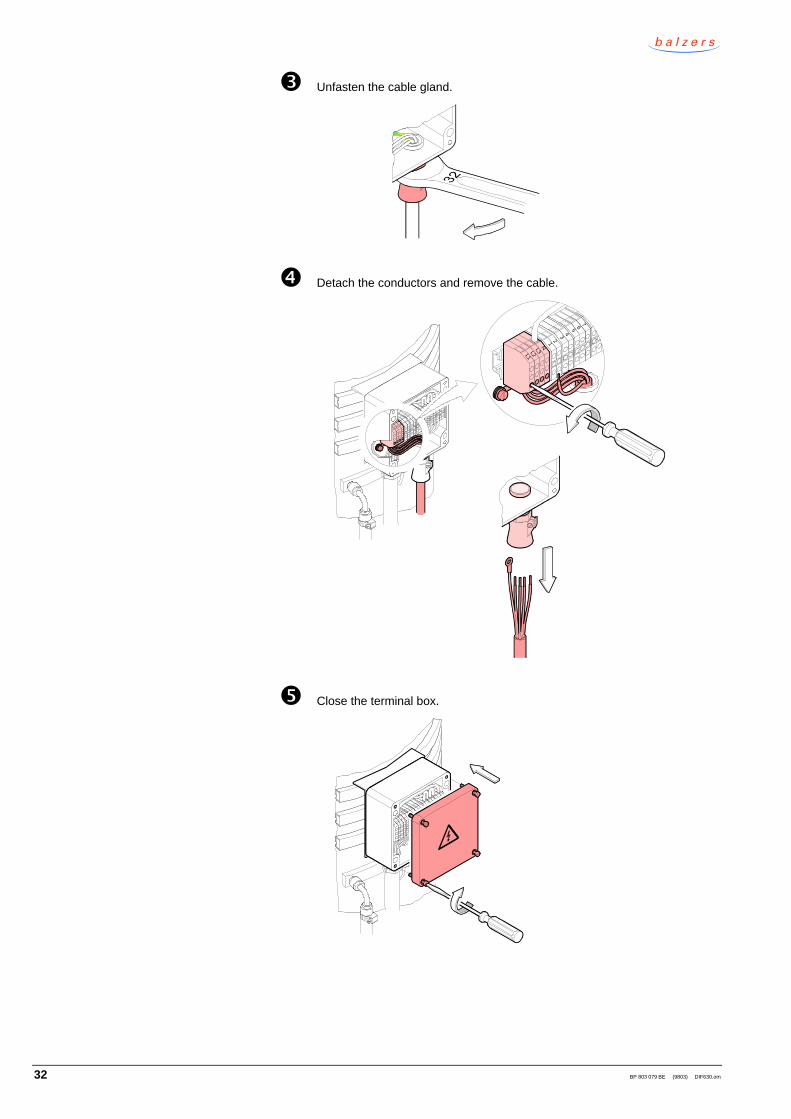
� Unfasten the cable gland.
� Detach the conductors and remove the cable.
8 910
1112
1314
L1L2
L3N
1 23
45 6
7
L1L2
L3N
1 23 4
5 6 7
� Close the terminal box.
89
1011
1213
14
L1L2
L3N
12
3 45
6 7
BP 803 079 BE (9803) DIF630.om 33
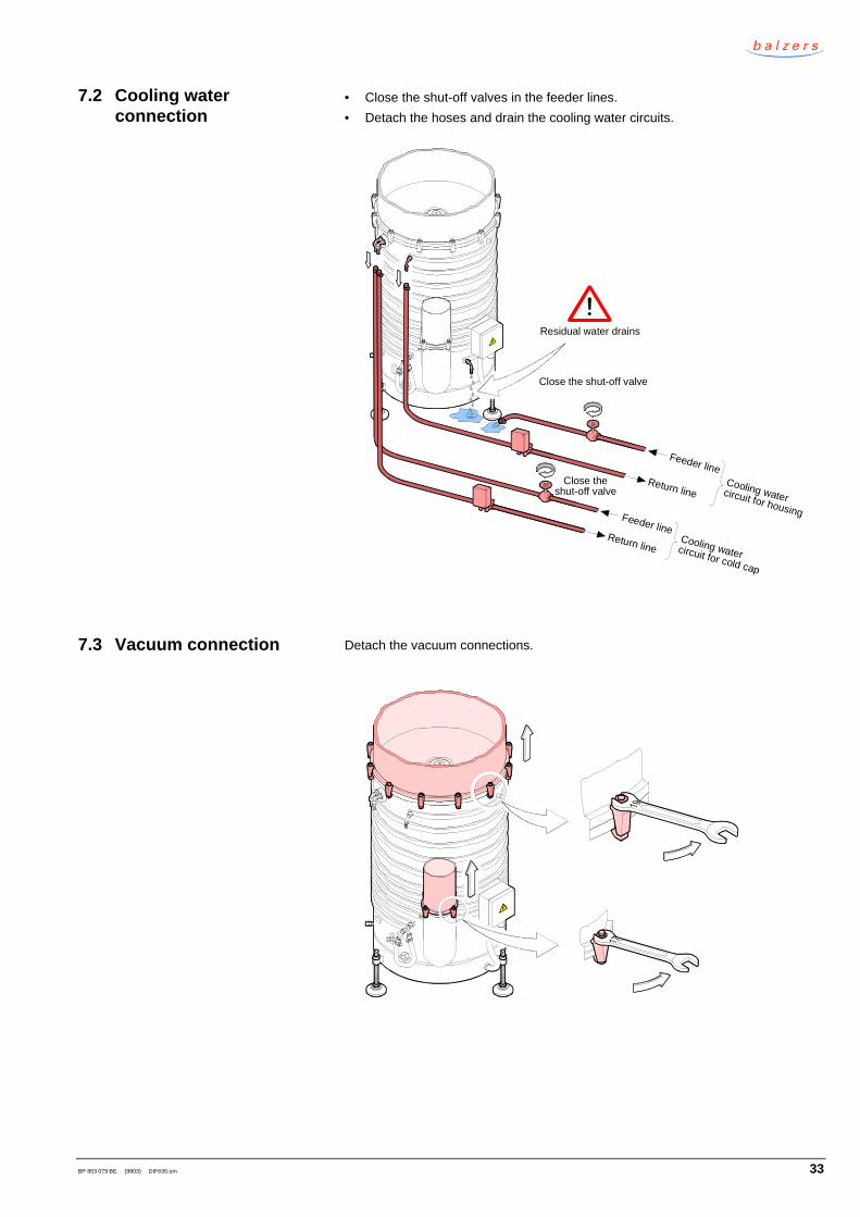
• Close the shut-off valves in the feeder lines.
• Detach the hoses and drain the cooling water circuits.
Residual water drains
Close the shut-off valve
Feeder lineReturn line
Close theshut-off valve
Cooling watercircuit for housing
Cooling watercircuit for cold cap
Feeder lineReturn line
Detach the vacuum connections.
7.2 Cooling waterconnection
7.3 Vacuum connection

34 BP 803 079 BE (9803) DIF630.om
è Remove the hose nozzle.
Seal
Union nut
Hose nozzle ø13
� Remove the elbow.
Sealed thread
� Unscrew the centering pin.
7.4 Deinstalling the cold cap

BP 803 079 BE (9803) DIF630.om 35
� Detach the cooling tube.
Counterhold.
Washer
Nut
� Detach the cold cap.
Washer
Hexagon socket screwM6 × 16
O-ring, FPM (Viton), ø20.2 × 2.6
Size 5

36 BP 803 079 BE (9803) DIF630.om
DANGER
Caution: pump fluid
Skin contact with the pump fluid can cause allergic reactions.
Wear synthetic gloves.
è Pull out the jet system.
Note
Caution: deformation of parts
The thin-walled aluminum parts are susceptible to deformation.
The aluminum parts must be treated with special care.
7.5 Draining the pump fluid

BP 803 079 BE (9803) DIF630.om 37
� Unscrew the upper part of the fore vacuum baffle.
� Pull out the upper part of the fore vacuum baffle.
� Pull out the lower part of the fore vacuum baffle.
Removing the fore vacuumbaffle

38 BP 803 079 BE (9803) DIF630.om
� Drain (or suck off) the pump fluid.
N
WARNING
Caution: substances detrimental to the environment
Products, operating materials etc. may have to be speciallydecommissioned.
For environmentally compatible disposal, please contact yournearest Balzers Service Center.
10 l
ò Reinstall the fore vacuum baffle, jet system, and cold cap.
ó Reinstall the protective cover and cap.

BP 803 079 BE (9803) DIF630.om 39
8 Troubleshooting
Pump fluidcontaminated
Cooling waterinsufficient
or too warm
Leak invacuumsystem
Heating platedefective
Thermostaticcut-outtripped
Check thepump fluid
level
Clean thediffusion
pump
Replace theheating plate
Reset thethermostatic
cut-out
Troubleshooting
Ultimatepressure
inadequate
Heaterdoes notfunction
Section 8.1
Cooling waterrequirements
Insufficientor excessivepump fluid
Pump fluidcontaminated
Clean thediffusion
pump
Remedythe leak
→ 2 20
Maintenance / Repair → 2 40
Pumpingspeed
inadequate
Poorheatersupport
If the heater has been switched off by the thermostatic cut-out (option) proceed asfollows:
Increase the cooling water flow
Press the reset button
Allow the diff pump to cool down for ≈ 2 min.
8.1 Resetting the thermo-static cut-out (option)

40 BP 803 079 BE (9803) DIF630.om
9 Maintenance / Repair
→ 2 41
Checking thepump fluid
level
→ 2 45
Replacing aheating plate
Replace thedefective
heating plate
Cleaning thediffusion pump
Clean thediffusion pump
Maintenance / Repair
Switch off the diffusion pump → 2 29
→ 2 42
Remove the pump → 2 30
Check thepump fluid leveland replenish,if necessary
DANGER
Caution: contaminated parts
Contaminated parts can be detrimental to health.
Before you begin to work, find out whether any parts are contami -nated. Adhere to the relevant regulations and take the necessaryprecautions when handling contaminated parts.
DANGER
Caution: pump fluid
Skin contact with the pump fluid can cause allergic reactions.
Wear synthetic gloves.
Note
Caution: vacuum component
Dirt and damages impair the function of the vacuum component.
When handling vacuum components, take appropriate measures toensure cleanliness and prevent damages.

BP 803 079 BE (9803) DIF630.om 41
Depending on the process conditions each diffusion pump has a pump fluid con -sumption, which is proportional to the pumped gas flow.
Note
The pump fluid level can only be checked when the diffusion pump iscold.
Pump fluid filling capacities:
maximum 8000 cm3
optimum 7000 cm3
too low < 6000 cm3
see Section 9.2
The pump fluid should only be replenished if processes are performed in which theevolution of products that impair the quality of the pump fluid does not exceed thepurification ability of the diffusion pump. In all other cases the pump fluid should bechanged. The diffusion pump should always be cleaned when the pump fluid ischanged.
• Diffusion pump switched off (→ 2 29) and cooled down to room temperature.
• Vacuum system vented.
è Detach the fore vacuum connection.
� Fill in the pump fluid (→ 2 16).
� Reestablish the fore vacuum connection.
9.1 Checking the pump fluidlevel
9.2 Replenishing the pumpfluid
Preconditions
Procedure

42 BP 803 079 BE (9803) DIF630.om
As the cleaning intervals depend strongly on the implemented vacuum process, nogenerally valid maintenance schedules can be prepared.
Under clean vacuum conditions and at operating pressures of <10 -4 mbar, diffu-sion pumps can be operated several 1000 hours without cleaning.
When the diffusion pump is cleaned, the related components (valves, lines, etc.)should also be cleaned.
• Diffusion pump removed and pump fluid drained ( → 2 30).
è Unfasten the lock nut.
Counterhold.
Wrenchsize 17
� Unfasten the hexagon nut.
For reassembly: Tighten thenut first using your fingers,then making 2½ turns with thewrench.
Wrenchsize 17
9.3 Cleaning the diffusionpump, replacing the jetsystem
Precondition
Disassembling the jet system

BP 803 079 BE (9803) DIF630.om 43
� Disassemble the jet system.
Do not adjustthe nozzle gapsetting screws(→ 2 44).
12 cup springs
Do not adjustthe nozzle gapsetting screws(→ 2 44).

44 BP 803 079 BE (9803) DIF630.om
� Clean the jet system, fore vacuum baffle, cold cap and the inside of thediffusion pump.
DANGER
Caution: cleaning agents
Cleaning agents can be detrimental to health and environment.
Adhere to the relevant regulations and take the necessary pre -cautions when handling and disposing of cleaning agents.Consider possible reactions with the product materials(→ 2 8).
• Clean the parts with a grease-cutting, non-scouring household cleaner.For removing resistant contamination (crack products) on the jet systemalso very fine steel wool can be used.
• The parts should preferably be rinsed with alcohol and subsequently beheated to ≈ 50 °C in an oven or with an industrial hot-air blower.
• Clean the sealing surfaces with a lint-free piece of cloth slightlymoistened with alcohol. Allow them to dry.
• Wipe the sealing rings with a lint-free piece of cloth slightly moistenedwith vacuum oil.
� Reassemble the diffusion pump by performing the above steps in reverseorder.
Note
• Be careful to insert the sealing rings into the lining grooveswithout twisting them.
• Make sure the prescribed nozzle gaps exist.
Nozzle gap 1.3±0.2 mmadjustable with 3 settingscrews
Setting screws lockedwith washers
Nozzle gap 1.5±0.2 mm adjustable with washers
Nozzle gap 3±0.2 mmadjustable with 3 settingscrews
Cleaning
Reassembly

BP 803 079 BE (9803) DIF630.om 45
Skilled personnel
Heating plates may be replaced only by a skilled electrician.
• Diffusion pump removed and pump fluid drained ( → 2 30).
è Turn the diffusion pump upside down.
250 kg
DANGER
Caution: heavy product (250 kg)
Physical injury can result if the product is lifted and transportedby only one person.
The product must be lifted and transported in accordance withthe rules and guidelines applicable in the country of installa -tion.
Mount theprotective
cover.
9.4 Replacing a heatingplatePersonnel qualifications
Precondition
Procedure

46 BP 803 079 BE (9803) DIF630.om
� Unfasten the hexagon head screws.
8
� Remove the hexagon head screws, the washers, and the cover.
Removing the cover

BP 803 079 BE (9803) DIF630.om 47
� Open the terminal box.
L1L2L3N
567
891011121314
1234
� Find the defective heating plate using the diagrams below.
In the following example it is assumed that the heating plate betweenterminals 3 and 10 is defective.
L2 L3L1 N PE
1
8
2
9
3
10
4
11
5
12
6
13
7
14
1.5
kW
1.5
kW
1.5
kW
1.5
kW
1.5
kW
1.5
kW
1.5
kW
L2 L3L1
1
8
2
9
3
10
4
11
5
12
6
13
7
14
PE
1.5
kW
1.5
kW
1.5
kW
1.5
kW
1.5
kW
1.5
kW
1.5
kW
Detaching the powerconnection
3×400 VACstar connection
3×230 VACdelta connection

48 BP 803 079 BE (9803) DIF630.om
ò Disconnect the lead of the defective heating plate (assumption: the heaterplate between terminals 3 and 10 is defective).
L1L2L3N
567891011121314
1234
ó Pull the cable out of the metal tube.

BP 803 079 BE (9803) DIF630.om 49
õ Unfasten the insulating plate.
ö Remove the insulating plate.
Removing the insulating plate

50 BP 803 079 BE (9803) DIF630.om
ú Unfasten the nut.
24
Tightening torque = 100 Nm
� Remove the nut, the washer, and the pressure plate.
Removing the pressure plate
BP 803 079 BE (9803) DIF630.om 51
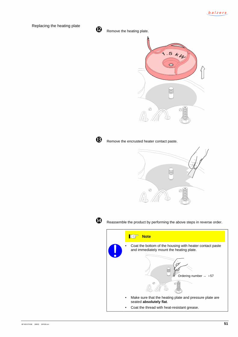
� Remove the heating plate.
� Remove the encrusted heater contact paste.
� Reassemble the product by performing the above steps in reverse order.
Note
• Coat the bottom of the housing with heater contact pasteand immediately mount the heating plate.
Ordering number → 2 57
• Make sure that the heating plate and pressure plate areseated absolutely flat.
• Coat the thread with heat-resistant grease.
Replacing the heating plate

52 BP 803 079 BE (9803) DIF630.om
10 Options
The flow monitor protects the diffusion pump from overheating by monitoring theflow rate of the cooling water.
Return line
Feeder line
Cooling watercircuit for housingCooling watercircuit for cold cap
Ordering number
Flow monitor B 4747 111 SE
Orifice 8-16 l/minfor cooling watercircuit for housing B 4747 311 SE
Orifice 2-4 l/minfor cooling watercircuit for cold cap B 4747 305 SE
Return line
Feeder line
The thermostatic cut-out prevents overheating of the diffusion pump.
Ordering numerBP 336 514 -T
10.1 Cooling water flowmonitor
10.2 Thermostatic cut-out

BP 803 079 BE (9803) DIF630.om 53
The thermal switch signals to the pumping station control that the diffusion pumphas attained normal operating temperature.
Ordering numberBG 540 077 -U
Baffles are used to reduce pump fluid backstreaming from the diffusion pump intothe process chamber.
Feeder line
Return lineReturn line
Feeder line
Ordering number
Water baffleBFA 630 W BP B07 001
Combi baffleBFA 630 MF BP B07 004
Additional information can be found in the catalog.
10.3 Thermal switch
10.4 Baffle
54 BP 803 079 BE (9803) DIF630.om
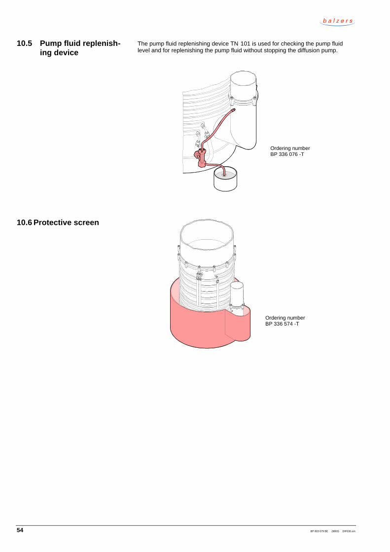
The pump fluid replenishing device TN 101 is used for checking the pump fluidlevel and for replenishing the pump fluid without stopping the diffusion pump.
Ordering numberBP 336 076 -T
Ordering numberBP 336 574 -T
10.5 Pump fluid replenish-ing device
10.6 Protective screen

BP 803 079 BE (9803) DIF630.om 55
11 Consumables
When ordering consumables, always indicate:
• description and ordering number
Container size Mineral oil 61 A
500 cm3 = ½ l2000 cm3 = 2 l5000 cm3 = 5 l
BD 480 137 -TBD 480 138 -TBD 480 139 -T
Container size Synthetic oil 71 A
500 cm3 = ½ l2000 cm3 = 2 l5000 cm3 = 5 l
BD 480 132 -TBD 480 133 -TBD 480 134 -T
Container size Silicone oil DC 704 Silicone oil AN 175
50 cm3
200 cm3
500 cm3 = ½ l2000 cm3 = 2 l5000 cm3 = 5 l
BD 480 090 -TBD 480 091 -TBD 480 092 -TBD 480 093 -TBD 480 094 -T
–BD 480 126 -TBD 480 127 -TBD 480 128 -TBD 480 129 -T
Container size Pentaphenyl etherSantovac 5
100 cm3
500 cm3 = ½lBD 480 558 -TBD 480 559 -T
Additional information can be found in the catalog or on page 16.
11.1 Pump fluid
Mineral oil
Synthetic oil
Silicone oil
Pentaphenyl ether

56 BP 803 079 BE (9803) DIF630.om
12 Spare parts
When ordering spare parts, always indicate:
• all information on the product nameplate
• description and ordering number
Ordering number BN 841 077 -Tcomprising:
Lock washer seal
Tightening torque = 80 Nm
O-ring, VitonAN 007ø 3.7 × 1.8
O-ring, VitonAN 475ø 658.9 × 7
O-ring, VitonAN 362ø 158.1 × 5.3
12.1 Seals

BP 803 079 BE (9803) DIF630.om 57
Ordering number BP 336 542 -T (Replacing a heating plate → 2 45)
Ordering number BN 845 295-T
20 g
Available on request. (Replacing the jet system → 2 42)
12.2 Heating plate
12.3 Heater contact paste
12.4 Jet system

58 BP 803 079 BE (9803) DIF630.om
13 Returning the product
WARNING
Caution: forwarding contaminated products
Products returned to Balzers for service or repair should preferably befree of harmful substances (e.g. radioactive, toxic, caustic or micro -biological).
Adhere to the forwarding regulations of all involved countries andforwarding companies and enclose a completed declaration ofcontamination.
Products that are not clearly declared as "free of harmful substances" are de -contaminated at the expense of the customer.
14 Disposal
DANGER
Caution: contaminated parts
Contaminated parts can be detrimental to health.
Before you begin to work, find out whether any parts are contami -nated. Adhere to the relevant regulations and take the necessaryprecautions when handling contaminated parts.
N
WARNING
Caution: substances detrimental to the environment
Products, operating materials etc. may require disposal in accordancewith special regulations.
For information on environmentally compatible disposal, pleasecontact your nearest Balzers Service Center.
After disassembling the product, separate its components according to thefollowing criteria:
Components which have been exposed to radioactive, toxic, caustic, or micro -biological process gases must be disposed of in accordance with the relevantnational regulations.
Components which have been exposed to other process gases must be separatedaccording to their materials and recycled.
Such components must be separated according to their materials and recycled.
Separating the components
Components exposed toprocess gases
Components not exposed toprocess gases

BP 803 079 BE (9803) DIF630.om 59
Declaration of Contamination
ò Legally binding declaration: I hereby declare that the information supplied on this form is complete and accurate. The dispatch of the contaminated product will be in accordance with the appropriate regulations covering packaging, transportation and labelling of dangerous substances.
Name of organisation or company
Address Post code
Phone Telex
Name
Date and legally binding signature Company stamp
� Harmful substances, gases and/or by-products Please list all substances, gases and by-products which may have come into contact with the product:
*) Products thus conta- minated will not be accepted without written evidence of decontamination!
� Process related contamination of product: toxic no q yes q
corrosive no q yes q
biological hazard no q yes q *)
explosive no q yes q *)
radioactive no q yes q *)
other harmful substances no q yes q
� Reason for return
The repair and/or service of vacuum equipment and components will only be carried out if a correctly completed declaration has beensubmitted. Non-completion will result in delay.This declaration can only be completed and signed by authorised and qualified staff.
è Description of product Type Article No. Serial No.
Copies: Original to manufacturer or representative - 1 copy attach to consignment packaging - 1 copy for file of sender
� Operating fluid(s) used
Trade/Product nameManufacturer
Chemical name(or symbol)
Dangerousmaterial class Measures if spillage
First aid in case ofhuman contact

Balzers InstrumentsPostfach 1000FL–9496 BalzersLiechtensteinTel +41 (0) 75 388 52 02Fax +41 (0) 75 388 54 58
Original: German BP 803 079 BD (9802) [email protected]
http://www.bi.balzers.com
Manufacturer’s declaration
Diffusion pumpwith optional baffle
DIF 630
We herewith declare that the above product is intended for installation into amachine and that the commissioning of said machine is not allowed until it hasbeen ascertained that the machine into which this product is to be installed con -forms to the specifications of the listed EU guidelines.
Guidelines, harmonised standards, national standards in languages and speci fi-cations which have been applied:
89/392/EEC version 93/68/EEC ...............................
EN 292-1+EN 292-2 / 9.91 ........................................
EN 60 204-1 / 10.92 ...................................................
73/23/EEC / 7.93...........................................................
.........................................................................................
Product management:
25 February 1998 Max Brehse ...............................
Development:
25 February 1998 Hugo Frei ...................................
Product
EU manufacturer’s declaration asdefined by the listed Guidelines
Signatures