with com a un centre una ma ma ma te the
TRANSCRIPT

WITH COM A UN CENTRE UNA MA MA MA TE THE US 20180083315A1 ( 19 ) United States ( 12 ) Patent Application Publication ( 10 ) Pub . No . : US 2018 / 0083315 A1
Christensen et al . ( 43 ) Pub . Date : Mar . 22 , 2018
( 54 ) COATED CATHODE ACTIVE MATERIAL FOR ENGINEERED SOLID - STATE BATTERY INTERFACES
( 71 ) Applicant : Robert Bosch GmbH , Stuttgart ( DE )
( 72 ) Inventors : John F . Christensen , Elk Grove , CA ( US ) ; Boris Kozinsky , Waban , MA ( US ) ; Sondra Hellstrom , East Palo Alto , CA ( US )
Publication Classification ( 51 ) Int . CI .
HOIM 10 / 0565 ( 2006 . 01 ) HOIM 10 / 0525 ( 2006 . 01 ) HOIM 4 / 525 ( 2006 . 01 )
2 ) U . S . CI . CPC . . HOIM 10 / 0565 ( 2013 . 01 ) ; HOLM 2004 / 028
( 2013 . 01 ) ; HOTM 4 / 525 ( 2013 . 01 ) ; HOIM 10 / 0525 ( 2013 . 01 )
ABSTRACT A solid - state lithium - ion battery includes an anode , a cath ode , and a separator . The cathode includes an active mate rial , a catholyte material , and a barrier layer coating only the active material . The barrier layer is configured to isolate physically the active material from direct contact with the catholyte material and to connect ionically the active mate rial and the catholyte material . The separator is located between the anode and the cathode and is configured to connect ionically the anode and the cathode and to isolate electronically the anode and the cathode .
( 57 )
( 21 ) Appl . No . : 15 / 704 , 124
( 22 ) Filed : Sep . 14 , 2017
Related U . S . Application Data ( 60 ) Provisional application No . 62 / 395 , 491 , filed on Sep .
16 , 2016 .
Patent Application Publication Mar . 22 , 2018 Sheet 1 of 10 US 2018 / 0083315 A1
* * *
116 120
PODDE - -
?????????????????????????????????????????????????????????????????????????????????????????????????????????????????????? 171 POO wwwwwwwwwwwwwwwwwwwwwwwwwwwwwwwwwwwwwwwwwwwwwwwwwwwwwwwwwwww -
- -
104 8th
951 Lobo FIG . 1 Second Moco

Patent Application Publication
COATING
Li?ne ( PO4 ) 3 Liz LazZr2012 AlPO4
136124
TTI
CAD
2002
160 2
138
142
n .
mund
ELECTROLYTE Linn Sn ( PSTTTTT47TATATATT41 Tlico 6 1 21T1414131 Liosco0oII8TITUTI Topo 5111i11411 Lio5c0061438 1 514
e
CATHODE
m
CATHODE
MMMMMMMMMM
1624
Mar . 22 , 2018 Sheet 2 of 10
met atom
S LIMPO4 127TTTTTTTTT Lin MPO T 4 213171 115 11 21 - MnPO05439III513 ]
LiMn1 . 5Nig . 50461171114
ELECTROLYTE
wa
voor
FIG . 2B
US 2018 / 0083315 A1
Patent Application Publication Mar . 22 , 2018 Sheet 3 of 10 US 2018 / 0083315 A1
- DISTANCE ww N . . . . . . - - - - - - - -
- - - - wwwww * * * * * * * *
e
? ENERGY ( meV / atom ) §
og - - - - NONE - - - - - - LizN - - - - LINbO3 LipoSn ( P5612 COATING LosCo02
( EXEMPLARY CATHODE Y . MPE CONDUCTIVE MATERIAL OF THE CATHODE )
wand 1 pocosok
- 2255 Aw ligps , 14
- -
- - - -
HIDRO - - - -
-
- - -
* * . . . - - -
vous i
LizP
1 TERFACER FIG . 4
Patent Application Publication
- 150
- - 152
- 156
- 158
Lj7 ANODE
* ANODE
I
Lit ANODE
1
SEIX
SEL SEIL
BSK * * * * * * * * * * * * * * * *
SOLID
ONOS
1110DB
01105
SOLID ELECTROLYTE
Mar . 22 , 2018 Sheet 4 of 10
ELECTROLYTE wwwwwwwwwww
ELECTROLYTE
ELECTROLYTE
-
-
- - -
-
- - -
-
- - -
- - -
-
- -
- - -
FIG . 5
US 2018 / 0083315 A1
UNCOATED
10 nm nom .
25 nm nom .
Patent Application Publication
: IC
1
- 36 TRI -
- 2008 :
DATE
- 200
-
I SPOT ! ND Dat Mag BATE
20 KV 3 $ mm ID 150000 x : 05 / 30 / 15 , 1617 |
HV SPOT WD Bei Mog DATE OFW
20 W 358 10 1 51000 x / 05 / 30 / 15 , 16 30 19 sum
HV sron Wo De Mcg .
MAW
20 KV 3 . 54mm ILD 150000 x 35 / 30 / 15 , 16 42 19 um
mm
FIG . 6A
Sooloo Bercool
FIG . 6C
UNCOATED
10 nm nom ,
25 nm nom .
Mar . 22 , 2018 Sheet 5 of 10
V
Det Det
- 20 %
SKY
SPON WO Dot 54 mm SE ne SE
kny DATE SAW
500x 35
1500 105 / 03 / 15 , 15 55 . 884 7um
HV 5 XV
SPOT WI 3 . 53 mm
MOU
Mou DAJE . HAN 150 x 05 / 16 / 15 , 17 19194 Zum
09 . do
253
M1 x Jasne , 1 552 FIG . 6F
US 2018 / 0083315 A1
FIG . 6D
FIG . 6E
Patent Application Publication
25000 ,
857
20000
Ni2p3 / 2 O - KLL 979
NI - LMM ( maybe )
MA - UMM ( moybe )
Ni - MM ( maybe )
Mn2p 644 , 655
AMA
Ols 533
Amewa
15000 -
wwerter
10000
Mn3p - 50
29
Mar . 22 , 2018 Sheet 6 of 10
5000
Ni3p p2p - p2 - 5 % Cls 287
5000
7
133 Mama 233 190 . 233 . med mera
on the host
t
ing
Lowwwwwwwwwwwwwwwwwwwwwwwwwwwwwwwwwwwwwwwwwwwwwwwwwwwwwwwwwwwwwwwwwwwwwwwwwwwwwwwwwwwwwwwwwwwwwwwwwwwwwwwwwwwwwww 200 200
400 400
600
008 800
1000
FIG . 7
US 2018 / 0083315 A1
Patent Application Publication Mar . 22 , 2018 Sheet 7 of 10 US 2018 / 0083315 A1
10 nm nom . 25 nm nom .
WV SPOT WO DA Mag DATE HAW - 200 sm - SW 3 57 mm . TID 150000 x05 / 16 / 15 , 1704 9um . . .
WYSPOTI WO OK O 0 mm not connecter
Mng DATE x 107 07 / 15 , 1209 WIMMWMMMMMMMMMMMMM
FIG . 8A FIG . 8B
10 nm nom . 25 nm nom .
N 5 KV
SPOT W ) Dart Mug H - 20 3 $ 8 mm SE . 1503 x 05 / 18 / 15 , 16 55 / 1942330 -
mm H V SPOT WD el Hog PAJE - 200 SK 13 . 55 mm Se 1500 x 05 / 06 / 15 , 15 58 1942 um
FIG . 8C Barbados Doo
??? 200 }
g $ 34 $ 3 } }
Patent Application Publication
I000 [ ???
{ 3 - Q
( 000 ??? ? J??
( muybe
??? 40 .
( } s - 287 ub3p - 36 + 37 $
jb . 3 – 29 { 25 }
36 } + 376 }
{ 22 + 235
Mar : 22 , 2018 Sheet 8 of 10
?? ???
?
20?
3 * * * ??
?
,
. . / t
200
4 00 43
00
800
1000 ?
6 FIG . }
US 2018 / 0083315 A1

Patent Application Publication Mar . 22 , 2018 Sheet 9 of 10 US 2018 / 0083315 A1
CHARGE TRANSFER RESISTANCE
BAFTER FORMATION O AFTER RATE TEST
Rin Olm
NCM523 _ UNCOATED NUN NCM523 _ li3P04 304 NCM523 _ LiNb03 NCM811 _ UNCOATED F Good
f .
www E F Sport w
the 2 AFTER FORMATION
AFTER RATE TEST for
Rin Ohm mondo
vel - - - - -
- erit
NCM523 _ UNCOATED NCM523 _ Li3P04 NCH523 _ LiNb03 NCM871 _ UNCOATED wo
Smederos Wa 1 )
DISCHARGE CAPACITY NORMALIZED TO THE 1SC / 10 DISCHARGE ???????? 2 - 60
. . . . . .
OTODA NOM523 - 04ST _ UNCOATED A TODA NCM523 - 045T L3P04 OTODA NCM523 - 04ST _ LiNbO3 ONCM811 _ NEZ1075 _ UNCOATED ( / 10 0 / 5 02 10 2 36 ( 10RPT
recommend bad w
Lodbor you pood root 77
Patent Application Publication Mar . 22 , 2018 Sheet 10 of 10 US 2018 / 0083315 A1
200
216 - 220 x264
236
Ver ??????????????????
260 1 .
minimom . com 204
248 232 / 246
wory Boots ock con
US 2018 / 0083315 A1 Mar . 22 , 2018
COATED CATHODE ACTIVE MATERIAL FOR ENGINEERED SOLID - STATE BATTERY
INTERFACES [ 0001 ] This application claims the benefit of priority of U . S . provisional application Ser . No . 62 / 395 , 491 , filed on Sep . 16 , 2016 , the disclosure of which is herein incorporated by reference in its entirety .
the catholyte material and the active material . The barrier layer is configured to isolate physically the active material from direct contact with the catholyte material and to connect ionically the active material and the catholyte material . The coated cathode electrode , which is also referred to herein as a composite cathode , may also include electronically conductive additives , such as carbon black and / or carbon fibers , and a polymeric binder ( e . g . , PVDF ) .
BRIEF DESCRIPTION OF THE FIGURES FIELD [ 0002 ] This disclosure relates to the field of lithium - ion batteries and in particular to solid - state lithium - ion batteries .
BACKGROUND [ 0003 ] Rechargeable lithium ion ( “ Li - ion " ) batteries are attractive energy storage systems for portable electronics and electric and hybrid - electric vehicles because of their high specific energy compared to other electrochemical energy storage devices . A typical Li - ion battery cell contains a negative electrode , a positive electrode , and a separator region between the negative and positive electrodes . Both electrodes contain active materials that insert or react with lithium reversibly . In some cases , the negative electrode may include lithium metal , which can be electrochemically dis solved and deposited reversibly . The separator typically contains an electrolyte with a lithium cation and serves as a physical barrier between the electrodes , such that none of the electrodes are electronically connected within the cell . [ 0004 ] Solid - state lithium - ion batteries contain electro lytes in the electrodes and / or the separator that are solid at an operating temperature of the battery . Solid - state lithium ion batteries , in contrast to conventional lithium - ion batter ies containing liquid electrolytes , have several advantages . The replacement of liquid electrolytes by solid - state elec trolytes makes it possible , for example , to reduce the risk of thermal runaway and to increase the safety and the cycle stability of the battery . [ 0005 ] The replacement of liquid electrolytes with solid electrolytes typically reduces the energy storage capacity of the cathode . For example , most known solid - state lithium ion batteries have significant interfacial issues , such as degradation and high electrical resistance between the cath ode and the catholyte . 10006 ] . For at least these reasons , further developments in the area of solid - state lithium - ion batteries are desirable .
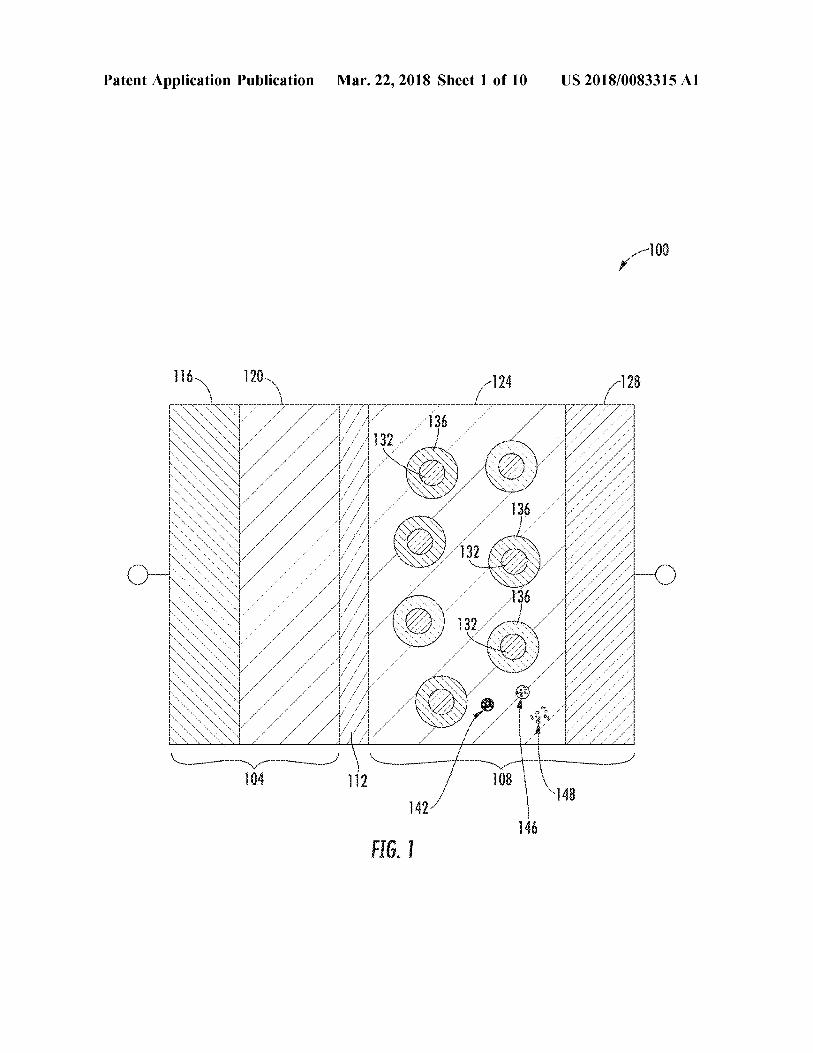
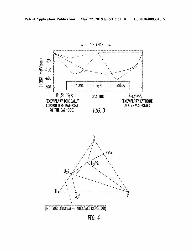
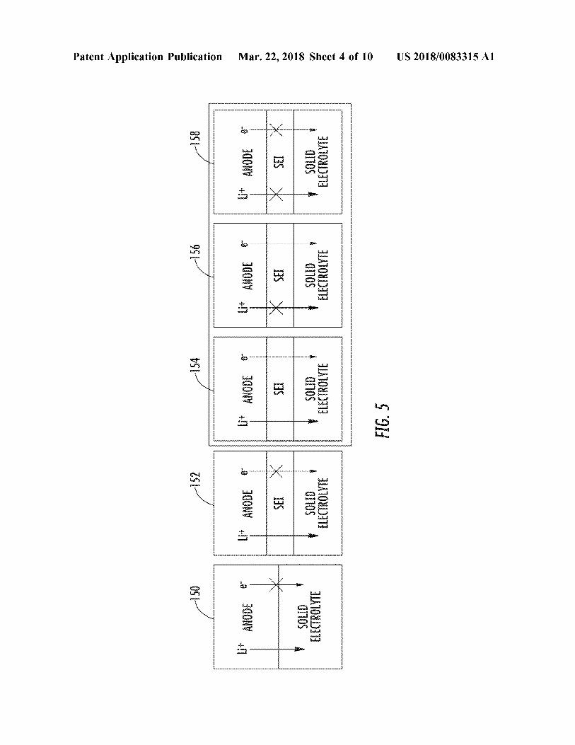
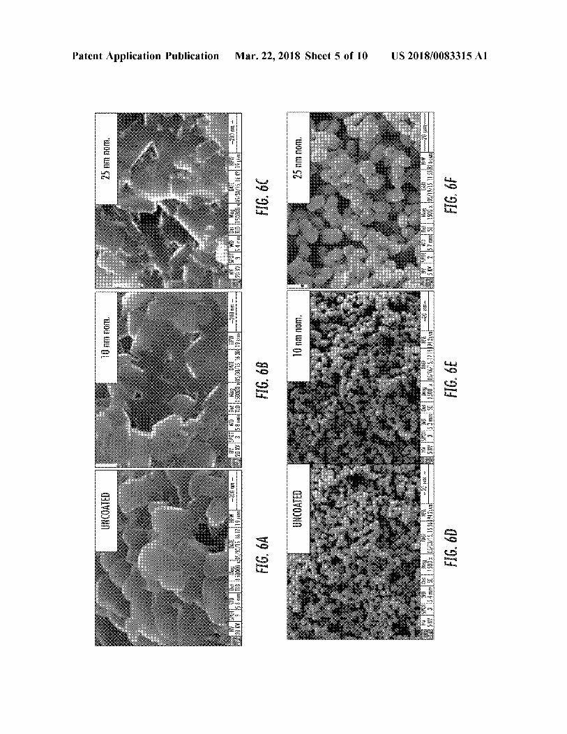
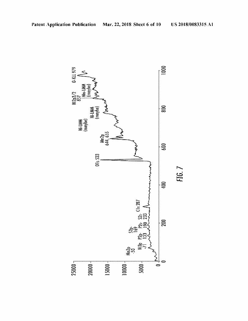
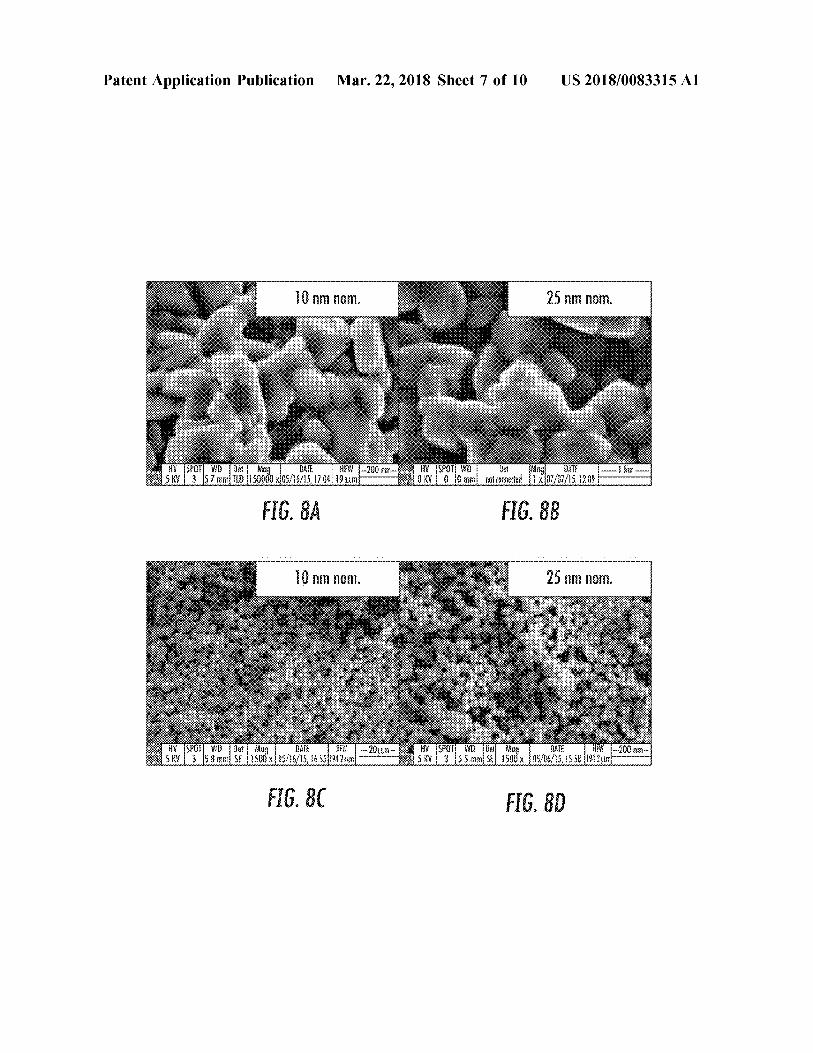
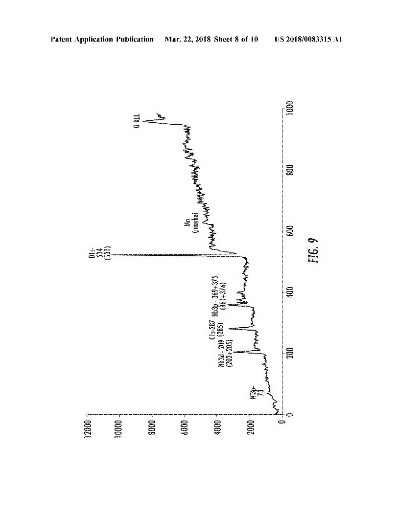
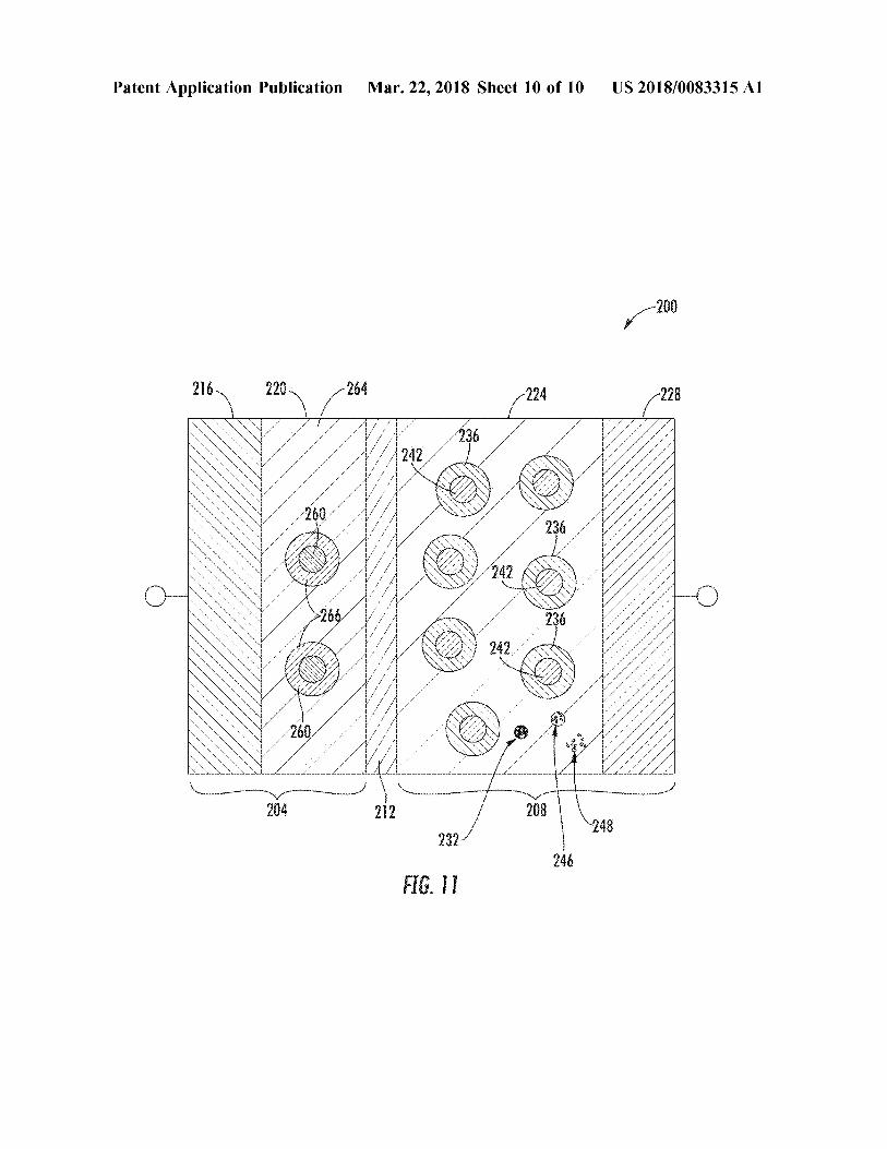
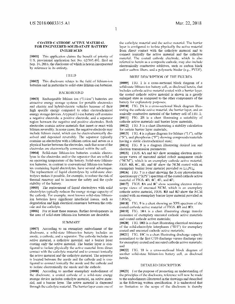
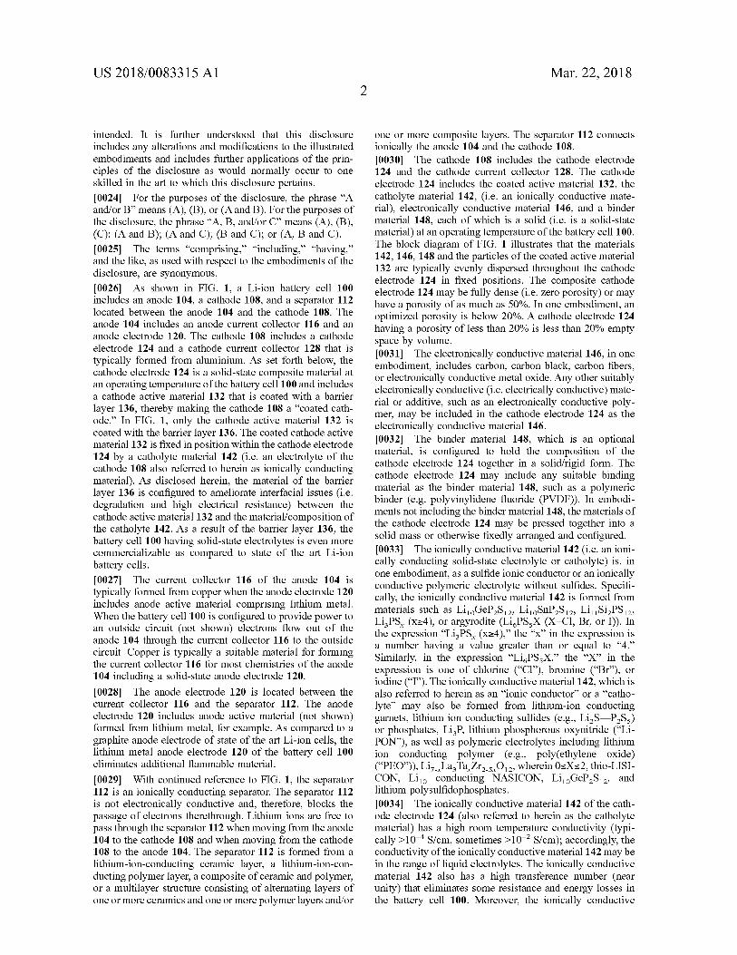
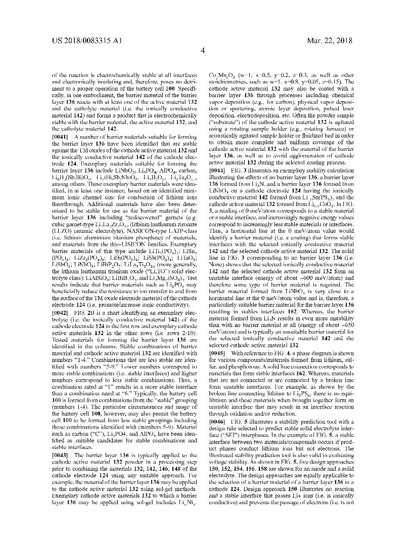
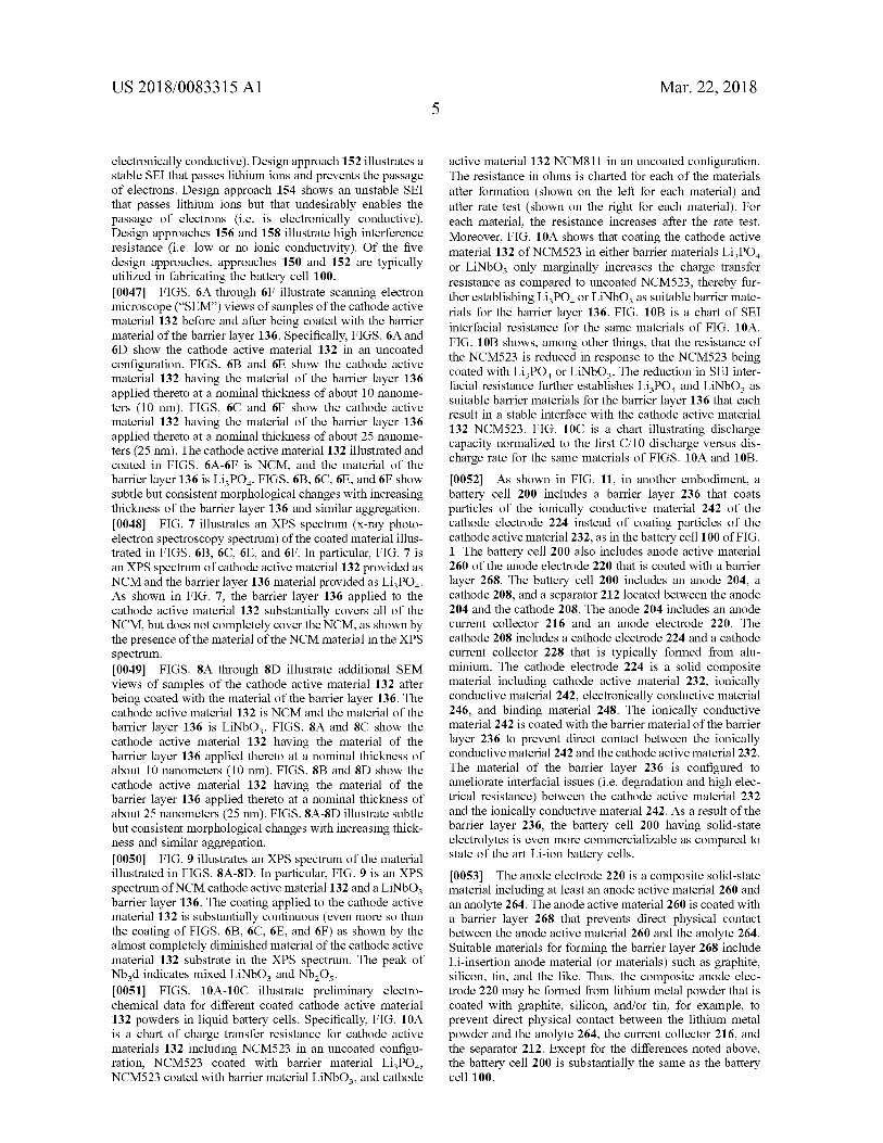
[ 0009 ] FIG . 1 is a cross - sectional block diagram of a solid - state lithium - ion battery cell , as disclosed herein , that includes cathode active material coated with a barrier layer , the coated cathode active material is shown in a greatly enlarged state as compared to the other components of the battery for explanatory purposes ; [ 0010 ] FIG . 2A is a cross - sectional block diagram illus trating the cathode active material , the barrier layer , and an ionically conductive material of the battery cell of FIG . 1 ; [ 0011 ] FIG . 2B is a chart illustrating a suitability of cathode active materials and barrier layer materials ; [ 0012 ] FIG . 3 is a chart illustrating a stability calculation for certain barrier layer materials ; [ 0013 ] FIG . 4 is a phase diagram for lithium ( “ Li ” ) , sulfur ( “ S ” ) , and phosphorus ( “ P ” ) showing compounds / materials having a stable electrochemical state ; [ 0014 ] FIG . 5 is a diagram illustrating desired ion and electron transmission parameters ; [ 0015 ] FIGS . 6A and 6D show scanning electron micro scope views of uncoated nickel cobalt manganese oxide ( “ NCM ” ) , which is an exemplary cathode active material , FIGS . 6B , 6C , 6E , and 6F show the NCM coated with an exemplary barrier layer material provided as LizPO . ; [ 0016 ] FIG . 7 is a chart showing the X - ray photoelectron spectroscopy ( “ XPS ” ) spectrum of the coated cathode active material of FIGS . 6B , 6C , 6E , and 6F ; [ 00171 FIGS . 8A and 8C show scanning electron micro scope views of uncoated NCM , which is an exemplary cathode active material , FIGS . 8B and 8D show the NCM coated with an exemplary barrier layer material provided as LiNbOz ; [ 0018 ] FIG . 9 is a chart showing an XPS spectrum of the coated cathode active material of FIGS . 8B and 8D ; [ 0019 ] FIG . 10A is a chart illustrating charge transfer resistance of exemplary uncoated cathode active materials and coated cathode active materials ; [ 0020 ] FIG . 10B is a chart illustrating electrical resistance of the solid - electrolyte interphases ( “ SEI ” ) for exemplary coated and uncoated cathode active materials ; [ 0021 ] FIG . 10C is a chart illustrating discharge capacity normalized to the first C / 10 discharge versus discharge rate for exemplary coated and uncoated cathode active materials ; and [ 0022 ] FIG . 11 is a cross - sectional block diagram of another solid - state lithium - ion battery cell , as disclosed herein .
SUMMARY [ 0007 ] According to an exemplary embodiment of the disclosure , a solid - state lithium - ion battery includes an anode , a cathode , and a separator . The cathode includes an active material , a catholyte material , and a barrier layer coating only the active material . The barrier layer is con figured to isolate physically the active material from direct contact with the catholyte material and to connect ionically the active material and the catholyte material . The separator is located between the anode and the cathode and is con figured to connect ionically the anode and the cathode and to isolate electronically the anode and the cathode . [ 0008 ] According to another exemplary embodiment of the disclosure , a coated cathode of a solid - state energy storage device includes catholyte material , an active mate rial , and a barrier layer . The active material is dispersed through the catholyte material . The barrier layer coats one of
DETAILED DESCRIPTION [ 0023 ] For the purpose of promoting an understanding of the principles of the disclosure , reference will now be made to the embodiments illustrated in the drawings and described in the following written specification . It is understood that no limitation to the scope of the disclosure is thereby
US 2018 / 0083315 A1 Mar . 22 , 2018
intended . It is further understood that this disclosure includes any alterations and modifications to the illustrated embodiments and includes further applications of the prin ciples of the disclosure as would normally occur to one skilled in the art to which this disclosure pertains . [ 0024 ] For the purposes of the disclosure , the phrase “ A and / or B ” means ( A ) , ( B ) , or ( A and B ) . For the purposes of the disclosure , the phrase " A , B , and / or C ” means ( A ) , ( B ) , ( C ) ; ( A and B ) ; ( A and C ) ; ( B and C ) ; or ( A , B and C ) . [ 0025 ] The terms “ comprising , ” “ including , ” “ having , " and the like , as used with respect to the embodiments of the disclosure , are synonymous . [ 0026 ] As shown in FIG . 1 , a Li - ion battery cell 100 includes an anode 104 , a cathode 108 , and a separator 112 located between the anode 104 and the cathode 108 . The anode 104 includes an anode current collector 116 and an anode electrode 120 . The cathode 108 includes a cathode electrode 124 and a cathode current collector 128 that is typically formed from aluminium . As set forth below , the cathode electrode 124 is a solid - state composite material at an operating temperature of the battery cell 100 and includes a cathode active material 132 that is coated with a barrier layer 136 , thereby making the cathode 108 a “ coated cath ode . ” In FIG . 1 , only the cathode active material 132 is coated with the barrier layer 136 . The coated cathode active material 132 is fixed in position within the cathode electrode 124 by a catholyte material 142 ( i . e . an electrolyte of the cathode 108 also referred to herein as ionically conducting material ) . As disclosed herein , the material of the barrier layer 136 is configured to ameliorate interfacial issues ( i . e . degradation and high electrical resistance ) between the cathode active material 132 and the material / composition of the catholyte 142 . As a result of the barrier layer 136 , the battery cell 100 having solid - state electrolytes is even more commercializable as compared to state of the art Li - ion battery cells . [ 0027 ] The current collector 116 of the anode 104 is typically formed from copper when the anode electrode 120 includes anode active material comprising lithium metal . When the battery cell 100 is configured to provide power to an outside circuit ( not shown ) electrons flow out of the anode 104 through the current collector 116 to the outside circuit . Copper is typically a suitable material for forming the current collector 116 for most chemistries of the anode 104 including a solid - state anode electrode 120 . [ 0028 ] The anode electrode 120 is located between the current collector 116 and the separator 112 . The anode electrode 120 includes anode active material ( not shown ) formed from lithium metal , for example . As compared to a graphite anode electrode of state of the art Li - ion cells , the lithium metal anode electrode 120 of the battery cell 100 eliminates additional flammable material . [ 0029 ] With continued reference to FIG . 1 , the separator 112 is an ionically conducting separator . The separator 112 is not electronically conductive and , therefore , blocks the passage of electrons therethrough . Lithium ions are free to pass through the separator 112 when moving from the anode 104 to the cathode 108 and when moving from the cathode 108 to the anode 104 . The separator 112 is formed from a lithium - ion - conducting ceramic layer , a lithium - ion - con - ducting polymer layer , a composite of ceramic and polymer , or a multilayer structure consisting of alternating layers of one or more ceramics and one or more polymer layers and / or
one or more composite layers . The separator 112 connects ionically the anode 104 and the cathode 108 . [ 0030 ] The cathode 108 includes the cathode electrode 124 and the cathode current collector 128 . The cathode electrode 124 includes the coated active material 132 , the catholyte material 142 , ( i . e . an ionically conductive mate rial ) , electronically conductive material 146 , and a binder material 148 , each of which is a solid ( i . e . is a solid - state material ) at an operating temperature of the battery cell 100 . The block diagram of FIG . 1 illustrates that the materials 142 , 146 , 148 and the particles of the coated active material 132 are typically evenly dispersed throughout the cathode electrode 124 in fixed positions . The composite cathode electrode 124 may be fully dense ( i . e . zero porosity ) or may have a porosity of as much as 50 % . In one embodiment , an optimized porosity is below 20 % . A cathode electrode 124 having a porosity of less than 20 % is less than 20 % empty space by volume . 10031 ] The electronically conductive material 146 , in one embodiment , includes carbon , carbon black , carbon fibers , or electronically conductive metal oxide . Any other suitably electronically conductive ( i . e . electrically conductive ) mate rial or additive , such as an electronically conductive poly mer , may be included in the cathode electrode 124 as the electronically conductive material 146 . [ 0032 ] The binder material 148 , which is an optional material , is configured to hold the composition of the cathode electrode 124 together in a solid / rigid form . The cathode electrode 124 may include any suitable binding material as the binder material 148 , such as a polymeric binder ( e . g . polyvinylidene fluoride ( PVDF ) ) . In embodi ments not including the binder material 148 , the materials of the cathode electrode 124 may be pressed together into a solid mass or otherwise fixedly arranged and configured . [ 0033 ] The ionically conductive material 142 ( i . e . an ioni cally conducting solid - state electrolyte or catholyte ) is , in one embodiment , as a sulfide ionic conductor or an ionically conductive polymeric electrolyte without sulfides . Specifi cally , the ionically conductive material 142 is formed from materials such as Li1oGeP S12 , Li1 SnP2S12 , LijlSi PS12 , LizPS , ( x24 ) , or argyrodite ( LigPS X ( X = C1 , Br , or I ) ) . In the expression “ LizPS , ( x24 ) , ” the “ x ” in the expression is a number having a value greater than or equal to “ 4 . " Similarly , in the expression “ LigPS X , ” the “ X ” in the expression is one of chlorine ( " C1 " ) , bromine ( “ Br ” ) , or iodine ( “ I ” ) . The ionically conductive material 142 , which is also referred to herein as an “ ionic conductor ” or a " catho lyte ” may also be formed from lithium - ion conducting garnets , lithium ion conducting sulfides ( e . g . , Li , S — P2S3 ) or phosphates , LizP , lithium phosphorous oxynitride ( “ Li PON ” ) , as well as polymeric electrolytes including lithium ion conducting polymer ( e . g . , poly ( ethylene oxide ) ( “ PEO " ) ) , Li7 - LazTa Zr2 - 54012 , wherein OsXs2 , thio - LISI CON , Lilo conducting NASICON , Li1 GeP $ 12 , and lithium polysulfidophosphates . [ 0034 ] The ionically conductive material 142 of the cath ode electrode 124 ( also referred to herein as the catholyte material ) has a high room temperature conductivity ( typi cally > 10 - 4 S / cm , sometimes > 10 - 2 S / cm ) ; accordingly , the conductivity of the ionically conductive material 142 may be in the range of liquid electrolytes . The ionically conductive material 142 also has a high transference number ( near unity ) that eliminates some resistance and energy losses in the battery cell 100 . Moreover , the ionically conductive

US 2018 / 0083315 A1 Mar . 22 , 2018
material 142 prevents poor electrode 124 utilization due to concentration gradients , and is typically soft enough that the electrode 124 can be processed without heating the electrode 124 beyond approximately 100° C . The ionically conductive material 142 is evenly dispersed through the cathode elec trode 124 . The solid - state ionically conductive material 142 eliminates the flammable organic electrolyte used in state of the art Li - ion cells . Sulfide electrolytes ( e . g . lithium tin phosphorus sulfide ( “ LSPS " ) ) are typically unstable against transition metal oxide cathode active materials 132 . As set forth below , interlayers , such as the barrier layer 136 , are beneficial in preventing reactions and forming stable inter faces 162 ( FIG . 2A ) . [ 0035 ] The cathode active material 132 is preferably a Li - insertion transition metal ( “ TM ” ) oxide material . In the one embodiment , the cathode active material 132 is in a powdered form including a plurality of particles of the cathode active material 132 . Exemplary materials for form ing the cathode active material 132 include LiNi0 . 8C00 . 15A10 . 0502 ( nickel cobalt aluminium ( “ NCA ” ) ) or another TM oxide such as LiC002 , LiMn204 , Li „ Ni Mn , Co , 02 , etc . In other embodiments , the cathode active material 132 may be another material such as a Li - insertion fluoride or oxy fluoride . TM oxides are typically preferred for the cathode active material 132 , because they have high capacities ( > 150 mAh / g and sometimes > 250 mAh / g ) , high voltages ( ~ 3 to 5 V vs . lithium , typically ) , and high cycle life ( > 1000 cycles , sometimes > 2000 cycles ) . The high capacity and voltage of the cathode active material 132 , coupled with the high capacity and low voltage of the lithium metal anode elec trode 120 , results in a battery cell 100 energy density that is much higher than state of the art Li - ion cells ( i . e . , > 300 Wh / kg and > 600 Wh / L , sometimes > 500 Wh / kg and > 1000 Wh / L ) . [ 0036 ] TM oxide cathode active materials 132 have numerous benefits as set forth above ; however , TM oxide cathode active materials 132 are typically unstable against sulfide electrolytes , as may be included in the ionically conductive material 142 of the cathode electrode 124 . That is , the cathode active material 132 should not come in direct physical contact with the electrolyte material ( s ) of the cathode electrode 124 . To prevent the direct physical con tact , the cathode electrode 124 includes the barrier layer 136 applied to the cathode active material 132 . The barrier layer 136 is configure to isolate physically the cathode active material 132 from the other materials of the cathode elec trode 124 ( specifically the ionically conductive material 142 ) , improves the long - term stability of the cathode elec trode 124 , and reduces the interfacial resistance between the ionically conductive material 142 and the cathode active material 132 , which would otherwise be high due to reac tions between the materials 132 , 142 . [ 0037 ] In FIG . 1 , the cathode active material 132 includes a plurality of sphere - like particles of powder , each particle of which is completely surrounded by an outer continuous shell of the barrier material of the barrier layer 136 . The barrier layer 136 completely prevents the cathode active material 132 from contacting directly any portion of the ionically conductive material 142 , such that the cathode active material 132 is completely physically isolated from the ionically conductive material 142 . The coated cathode active material 132 is typically evenly dispersed throughout the materials of cathode electrode 124 in a desired concen tration level . In other embodiments , the particles of cathode
active material 132 have any size and shape that is suitable for accepting a continuous coating of the barrier material of the barrier layer 136 . 10038 ] As shown in FIG . 2A , the barrier layer 136 is a sphere - like “ shell ” located around each sphere - like particle of the cathode active material 132 . In one embodiment , the barrier layer 136 defines a radial thickness 160 that is less than a diameter of the particle of the cathode active material 132 . In other embodiments , the thickness of the barrier layer is different ( thicker or thinner ) depending on the configura tion of the cathode electrode 124 . With reference to FIG . 1 , the barrier layer 136 is included on only the cathode active material 132 and the barrier layer 136 does not surround the ionically conductive material 142 . In other embodiments , the barrier layer 136 surrounds the ionically conductive material 142 and does not surround the cathode active material 132 ( FIG . 11 ) . In yet another embodiment , the barrier layer 136 surrounds the cathode active material 132 and the ionically conductive material 142 . [ 0039 ] The barrier layer 136 is typically a continuous or substantially continuous layer that extends completely around each particle of the cathode active material 132 . The barrier layer 136 prevents physical contact between the cathode active material 132 and the ionically conductive material 142 . Stated differently , the barrier layer 136 isolates physically the cathode active material 132 and the ionically conductive material 142 of the cathode electrode 124 . The barrier layer 136 also spaces apart each particle of the cathode active material 132 from the ionically conductive material 142 . The barrier layer 136 , however , does ionically connect the cathode active material 132 and the ionically conductive material 142 . That is , the barrier material of the barrier layer 136 , in at least one embodiment , is highly ionically conductive to enable the free transfer of lithium ions therethrough . This includes enabling the coated cathode active material 132 to receive lithium ions from the ionically conductive material 142 through the barrier layer 136 and enabling the coated cathode material 132 to release lithium ions into the ionically conductive material 142 through the barrier layer 136 . Moreover , in at least some embodiments , the barrier material of the barrier layer 136 has a low electronic conductivity to prevent the flow of electrons therethrough . Thus , in at least one embodiment , the barrier layer 136 prevents electron flow between the ionically conductive material 142 and the cathode active material 132 and prevents an electrical connection between the ionically conductive material 142 and the cathode active material 132 . [ 0040 ] The barrier layer 136 is configured to form at least two stable interfaces 162 . The first stable interface 162 is formed between the barrier layer 136 and the cathode active material 132 , and the second stable interface 162 is formed between the barrier layer 136 and the other materials of the cathode electrode 124 including the ionically conductive material 142 . As used herein , a “ stable interface ” is an interface that is at least electrochemically stable . At the stable interfaces 162 , the barrier material of the barrier layer 136 does not oxidize or reduce with the materials of the cathode active material 132 , the ionically conductive mate rial 142 , the electronically conductive material 146 , and the binder material 148 . In some embodiments , the barrier layer 136 may react with other components of the cathode elec trode 124 ( i . e . the cathode active material 132 , the ionically conductive material 142 , the electronically conductive mate rial 146 , and the binder material 148 ) ; however , the product
US 2018 / 0083315 A1 Mar . 22 , 2018
of the reaction is electrochemically stable at all interfaces and electronically insulating and , therefore , poses no detri ment to a proper operation of the battery cell 100 . Specifi cally , in one embodiment , the barrier material of the barrier layer 136 reacts with at least one of the active material 132 and the catholyte material ( i . e . the ionically conductive material 142 ) and forms a product that is electrochemically stable with the barrier material , the active material 132 , and the catholyte material 142 . [ 0041 ] A number of barrier materials suitable for forming the barrier layer 136 have been identified that are stable against the TM oxides of the cathode active material 132 and the ionically conductive material 142 of the cathode elec trode 124 . Exemplary materials suitable for forming the barrier layer 136 include LiNbO2 , Li3PO4 , AIPO4 , carbon , Li B3 ( Sb , Bi ) 09 , Liz ( Bi , Sb , Nb ) O . , Li _ B205 , LizTa _ 011 , among others . These exemplary barrier materials were iden tified , in at least one instance , based on an identified mini mum ionic channel size for conduction of lithium ions therethrough . Additional materials have also been deter mined to be stable for use as the barrier material of the barrier layer 136 including “ rediscovered ” garnets ( e . g . cubic garnet - type Li La Zr 0 , - ( lithium lanthanum zironate ( LLZO ) ceramic electrolyte ) , NASICON - type LATP - class ( i . e . lithium aluminium titanium phosphate ) of materials , and materials from the thio - LISICON families . Exemplary barrier materials of this type include LiTi ( PO ) ; LiSn , ( PO4 ) 3 ; LiZr2 ( PO4 ) 3 ; LiBi ( PO3 ) ; LiSb ( PO3 ) 4 ; LiTaOz ; LiSbO3 ; LiNbOz ; LiBiP207 ; LiLa , Ti 024 ( more generally , the lithium lanthanum titanium oxide ( “ LLTO ” ) solid elec trolyte class ) ; LiA1Si04 ; LiBiB , Os ; and LizMg2 ( SO4 ) 3 . Test results indicate that barrier materials such as LizP04 may beneficially reduce the resistance to ion transfer to and from the surface of the TM oxide electrode material of the cathode electrode 124 ( i . e . promote / increase ionic conductivity ) . [ 0042 ] FIG . 2B is a chart identifying an exemplary elec trolyte ( i . e . the ionically conductive material 142 ) of the cathode electrode 124 in the first row and exemplary cathode active materials 132 in the other rows ( i . e . rows 2 - 10 ) . Tested materials for forming the barrier layer 136 are identified in the columns . Stable combinations of barrier material and cathode active material 132 are identified with numbers “ 1 - 4 . ” Combinations that are less stable are iden tified with numbers “ 5 - 9 . ” Lower numbers correspond to more stable combinations ( i . e . stable interfaces ) and higher numbers correspond to less stable combinations . Thus , a combination rated at “ 1 ” results in a more stable interface than a combination rated at “ 6 . ” Typically , the battery cell 100 is formed from combinations from the “ stable ” grouping ( numbers 1 - 4 ) . The particular circumstances and usage of the battery cell 100 , however , may also permit the battery cell 100 to be formed from less stable groupings including those combinations identified with ( numbers 5 - 9 ) . Material such as carbon ( “ C ” ) , LizPO4 , and AIPO4 have been iden tified as suitable candidates for stable combinations and stable interfaces . [ 0043 ] The barrier layer 136 is typically applied to the cathode active material 132 powder in a processing step prior to combining the materials 132 , 142 , 146 , 148 of the cathode electrode 124 using any suitable approach . For example , the material of the barrier layer 136 may be applied to the cathode active material 132 using sol - gel methods . Exemplary cathode active materials 132 to which a barrier layer 136 may be applied using sol - gel includes Li „ Ni ,
CoMn 02 ( w = 1 , x = 0 . 5 , y = 0 . 2 , z = 0 . 3 , as well as other stoichiometries , such as w = 1 , x = 0 . 8 , y = 0 . 05 , z = 0 . 15 ) . The cathode active material 132 may also be coated with a barrier layer 136 through processes including chemical vapor deposition ( e . g . , for carbon ) , physical vapor deposi tion or sputtering , atomic layer deposition , pulsed laser deposition , electrodeposition , etc . Often the powder sample ( “ substrate ” ) of the cathode active material 132 is agitated using a rotating sample holder ( e . g . , rotating furnace ) or acoustically agitated sample holder or fluidized bed in order to obtain more complete and uniform coverage of the cathode active material 132 with the material of the barrier layer 136 , as well as to avoid agglomeration of cathode active material 132 during the selected coating process . [ 0044 ] FIG . 3 illustrates an exemplary stability calculation illustrating the effects of no barrier layer 136 , a barrier layer 136 formed from LizN , and a barrier layer 136 formed from LiNbOz on a cathode electrode 124 having the ionically conductive material 142 formed from Li , Sn ( PS ) , and the cathode active material 132 formed from Li , C002 . In FIG . 3 , a reading of O meV / atom corresponds to a stable material or a stable interface , and increasingly negative energy values correspond to increasingly less stable materials or interfaces . Thus , a horizontal line at the O meV / atom value would identify a barrier material ( i . e . a coating ) that forms stable interfaces with the selected ionically conductive material 142 and the selected cathode active material 132 . The solid line in FIG . 3 corresponding to no barrier layer 136 ( i . e . None ) shows that the selected ionically conductive material 142 and the selected cathode active material 132 form an unstable interface ( energy of about - 600 meV / atom ) and therefore some type of barrier material is required . The barrier material formed from LiNbO , is very close to a horizontal line at the O meV / atom value and is , therefore , a particularly suitable barrier material for the barrier layer 136 resulting in stables interfaces 162 . Whereas , the barrier material formed from LizN results in even more instability than with no barrier material at all ( energy of about - 650 meV / atom ) and is typically an unsuitable barrier material for the selected ionically conductive material 142 and the selected cathode active material 132 . [ 0045 ] With reference to FIG . 4 , a phase diagram is shown for various compounds / materials formed from lithium , sul fur , and phosphorous . A solid line connection corresponds to materials that form stable interfaces 162 . Whereas , materials that are not connected or are connected by a broken line form unstable interfaces . For example , as shown by the broken line connecting lithium to Li PS2 , there is no equi librium and these materials when brought together form an unstable interface that may result in an interface reaction through oxidation and / or reduction . 10046 ) FIG . 5 illustrates a stability prediction tool with a design rule selected to predict stable solid electrolyte inter face ( “ SEI ” ) interphases . In the example of FIG . 5 , a stable interface between two materials / compounds occurs if prod uct phases conduct lithium ions but not electrons . The illustrated stability prediction tool is also valid in evaluating voltage stability . As shown in FIG . 5 , five design approaches 150 , 152 , 154 , 156 , 158 are shown for an anode and a solid electrolyte . The design approaches are equally applicable to the selection of a barrier material of a barrier layer 136 in a cathode 124 . Design approach 150 illustrates no reaction and a stable interface that passes Li + ions ( i . e . is ionically conductive ) and prevents the passage of electrons ( i . e . is not
US 2018 / 0083315 A1 Mar . 22 , 2018
electronically conductive ) . Design approach 152 illustrates a stable SEI that passes lithium ions and prevents the passage of electrons . Design approach 154 shows an unstable SEI that passes lithium ions but that undesirably enables the passage of electrons ( i . e . is electronically conductive ) . Design approaches 156 and 158 illustrate high interference resistance ( i . e . low or no ionic conductivity ) . Of the five design approaches , approaches 150 and 152 are typically utilized in fabricating the battery cell 100 . [ 0047 ] FIGS . 6A through 6F illustrate scanning electron microscope ( “ SEM ” ) views of samples of the cathode active material 132 before and after being coated with the barrier material of the barrier layer 136 . Specifically , FIGS . 6A and 6D show the cathode active material 132 in an uncoated configuration . FIGS . 6B and 6E show the cathode active material 132 having the material of the barrier layer 136 applied thereto at a nominal thickness of about 10 nanome ters ( 10 nm ) . FIGS . 6C and 6F show the cathode active material 132 having the material of the barrier layer 136 applied thereto at a nominal thickness of about 25 nanome ters ( 25 nm ) . The cathode active material 132 illustrated and coated in FIGS . 6A - 6F is NCM , and the material of the barrier layer 136 is Liz PO4 . FIGS . 6B , 6C , 6E , and 6F show subtle but consistent morphological changes with increasing thickness of the barrier layer 136 and similar aggregation . [ 0048 ] FIG . 7 illustrates an XPS spectrum ( x - ray photo electron spectroscopy spectrum ) of the coated material illus trated in FIGS . 6B , 6C , 6E , and 6F . In particular , FIG . 7 is an XPS spectrum of cathode active material 132 provided as NCM and the barrier layer 136 material provided as LizPO4 . As shown in FIG . 7 , the barrier layer 136 applied to the cathode active material 132 substantially covers all of the NCM , but does not completely cover the NCM , as shown by the presence of the material of the NCM material in the XPS spectrum . [ 0049 ] FIGS . 8A through 8D illustrate additional SEM views of samples of the cathode active material 132 after being coated with the material of the barrier layer 136 . The cathode active material 132 is NCM and the material of the barrier layer 136 is LiNbOz . FIGS . 8A and 8C show the cathode active material 132 having the material of the barrier layer 136 applied thereto at a nominal thickness of about 10 nanometers ( 10 nm ) . FIGS . 8B and 8D show the cathode active material 132 having the material of the barrier layer 136 applied thereto at a nominal thickness of about 25 nanometers ( 25 nm ) . FIGS . 8A - 8D illustrate subtle but consistent morphological changes with increasing thick ness and similar aggregation . 100501 FIG . 9 illustrates an XPS spectrum of the material illustrated in FIGS . 8A - 8D . In particular , FIG . 9 is an XPS spectrum of NCM cathode active material 132 and a LiNbOz barrier layer 136 . The coating applied to the cathode active material 132 is substantially continuous ( even more so than the coating of FIGS . 6B , 6C , 6E , and 6F ) as shown by the almost completely diminished material of the cathode active material 132 substrate in the XPS spectrum . The peak of Nb d indicates mixed LiNbO2 and Nb 05 . [ 0051 ] FIGS . 10A - 10C illustrate preliminary electro chemical data for different coated cathode active material 132 powders in liquid battery cells . Specifically , FIG . 10A is a chart of charge transfer resistance for cathode active materials 132 including NCM523 in an uncoated configu ration , NCM523 coated with barrier material LizPO4 , NCM523 coated with barrier material LiNbOz , and cathode
active material 132 NCM811 in an uncoated configuration . The resistance in ohms is charted for each of the materials after formation ( shown on the left for each material ) and after rate test shown on the right for each material ) . For each material , the resistance increases after the rate test . Moreover , FIG . 10A shows that coating the cathode active material 132 of NCM523 in either barrier materials LizPO or LiNbOz only marginally increases the charge transfer resistance as compared to uncoated NCM523 , thereby fur ther establishing Li PO , or LiNbO , as suitable barrier mate rials for the barrier layer 136 . FIG . 10B is a chart of SEI interfacial resistance for the same materials of FIG . 10A . FIG . 10B shows , among other things , that the resistance of the NCM523 is reduced in response to the NCM523 being coated with LizP04 or LiNb03 . The reduction in SEI inter facial resistance further establishes Li PO , and LiNbO , as suitable barrier materials for the barrier layer 136 that each result in a stable interface with the cathode active material 132 NCM523 . FIG . 10C is a chart illustrating discharge capacity normalized to the first C / 10 discharge versus dis charge rate for the same materials of FIGS . 10A and 10B . 10052 ] . As shown in FIG . 11 , in another embodiment , a battery cell 200 includes a barrier layer 236 that coats particles of the ionically conductive material 242 of the cathode electrode 224 instead of coating particles of the cathode active material 232 , as in the battery cell 100 of FIG . 1 . The battery cell 200 also includes anode active material 260 of the anode electrode 220 that is coated with a barrier layer 268 . The battery cell 200 includes an anode 204 , a cathode 208 , and a separator 212 located between the anode 204 and the cathode 208 . The anode 204 includes an anode current collector 216 and an anode electrode 220 . The cathode 208 includes a cathode electrode 224 and a cathode current collector 228 that is typically formed from alu minium . The cathode electrode 224 is a solid composite material including cathode active material 232 , ionically conductive material 242 , electronically conductive material 246 , and binding material 248 . The ionically conductive material 242 is coated with the barrier material of the barrier layer 236 to prevent direct contact between the ionically conductive material 242 and the cathode active material 232 . The material of the barrier layer 236 is configured to ameliorate interfacial issues ( i . e . degradation and high elec trical resistance ) between the cathode active material 232 and the ionically conductive material 242 . As a result of the barrier layer 236 , the battery cell 200 having solid - state electrolytes is even more commercializable as compared to state of the art Li - ion battery cells . [ 0053 ] The anode electrode 220 is a composite solid - state material including at least an anode active material 260 and an anolyte 264 . The anode active material 260 is coated with a barrier layer 268 that prevents direct physical contact between the anode active material 260 and the anolyte 264 . Suitable materials for forming the barrier layer 268 include Li - insertion anode material ( or materials ) such as graphite , silicon , tin , and the like . Thus , the composite anode elec trode 220 may be formed from lithium metal powder that is coated with graphite , silicon , and / or tin , for example , to prevent direct physical contact between the lithium metal powder and the anolyte 264 , the current collector 216 , and the separator 212 . Except for the differences noted above , the battery cell 200 is substantially the same as the battery cell 100 .

US 2018 / 0083315 A1 Mar . 22 , 2018
[ 0054 ] While the disclosure has been illustrated and described in detail in the drawings and foregoing descrip tion , the same should be considered as illustrative and not restrictive in character . It is understood that only the pre ferred embodiments have been presented and that all changes , modifications , and further applications that come within the spirit of the disclosure are desired to be protected . What is claimed is : 1 . A solid - state lithium - ion battery comprising : an anode ; a cathode including an active material , a catholyte mate
rial , and a barrier layer coating only the active material , the barrier layer configured to isolate physically the active material from direct contact with the catholyte material and to connect ionically the active material and the catholyte material ; and
a separator located between the anode and the cathode and configured to connect ionically the anode and the cathode and to isolate electronically the anode and the cathode .
2 . The solid - state battery of claim 1 , wherein the active material is configured to accept lithium ions through the barrier layer and to release lithium ions through the barrier layer .
3 . The solid - state battery of claim 1 , wherein the barrier layer prevents electron flow between the catholyte material and the active material .
4 . The solid - state battery of claim 1 , wherein : the active material is configured as a plurality of active material particles each having a fixed position in the cathode , and
each active material particle of the plurality of active material particles is coated with the barrier layer , such that each active material particle is spaced apart from the catholyte material by the barrier layer .
5 . The solid - state battery of claim 1 , wherein : a first stable interface is formed between the active
material and the barrier layer , and a second stable interface is formed between the barrier
layer and the catholyte material . 6 . The solid - state battery of claim 1 , wherein : the barrier layer is formed from Li PO4 , and the active material is formed from nickel cobalt manga
nese oxide ( “ NCM ” ) . 7 . The solid - state battery of claim 6 , wherein the catholyte
material is formed from a lithium ion conducting polymer . 8 . The solid - state battery of claim 1 , wherein : the active material is a solid at an operating temperature of the battery cell ,
the catholyte material is a solid at the operating tempera ture of the battery cell , and
the barrier layer is formed from a barrier material that is a solid at the operating temperature of the battery cell .
9 . A coated cathode of a solid - state energy storage device , comprising :
a catholyte material ; an active material dispersed through the catholyte mate
rial ; and a barrier layer coating only one of the catholyte material
and the active material , the barrier layer configured to isolate physically the active material from direct con tact with the catholyte material and to connect ionically the active material and the catholyte material .
10 . The coated cathode of claim 9 , wherein the active material is configured to accept lithium ions through the barrier layer and to release lithium ions through the barrier layer .
11 . The coated cathode of claim 9 , wherein the barrier layer prevents electron flow between the catholyte material and the active material .
12 . The coated cathode of claim 9 , wherein : the active material is configured as a plurality of active
material particles each having a fixed position relative to the catholyte material , and
each active material particle of the plurality of active material particles is coated with the barrier layer , such that each active material particle is spaced apart from the catholyte material by the barrier layer .
13 . The coated cathode of claim 9 , wherein : a first stable interface is formed between the active
material and the barrier layer , and a second stable interface is formed between the barrier
layer and the catholyte material . 14 . The coated cathode of claim 10 , wherein : the first stable interface passes lithium ions and prevents
passage of electrons , and the second stable interface passes lithium ions and pre
vents passage of electrons . 15 . The coated cathode of claim 9 , wherein : the barrier layer is formed from Li PO , , and the active material is formed from nickel cobalt manga
nese oxide ( “ NCM ” ) . 16 . The coated cathode of claim 15 , wherein the catholyte
material is formed from a lithium ion conducting polymer . 17 . The coated cathode of claim 9 , wherein : the active material is a solid at an operating temperature
of the energy storage device , the catholyte material is a solid at the operating tempera
ture of the energy storage device , and the barrier layer is formed from a barrier material that is
a solid at the operating temperature of the energy storage device .
18 . The coated cathode of claim 9 , wherein the barrier material reacts with at least one of the active material and the catholyte material and forms a product that is electrochemi cally stable with the barrier material , the active material , and the catholyte material .
19 . The coated cathode of claim 9 , wherein the catholyte material , the active material , and the barrier layer have a porosity of up to 50 % .
* * * * *