wiring & installation manual - battery management system · wiring & installation manual...
TRANSCRIPT

Wiring & Installation Manual
Revision 2
The Orion Jr. BMS by Ewert Energy Systems is designed to manage and protect Lithium ion
battery packs and is suitable for use in stationary energy storage and small mobile applications such as
golf carts and material handling equipment.

Orion Jr. BMS Manual – Rev. 2
2
Table of Contents
SAFETY: READ THIS FIRST ................................................................................................................ 4
Determining which BMS to order ........................................................................................................ 7
Overview of Theory of Operation ........................................................................................................ 8
Mounting .............................................................................................................................................. 9
Physical Mounting .................................................................................................................................................................... 9
Thermal Information ................................................................................................................................................................. 9
Wiring the BMS .................................................................................................................................. 10
Interfacing the Load and Charger with the BMS .............................................................................. 11
Current Limiting via the digital CANBUS (CAN-enabled units only) ....................................................................................... 11
Current limiting via the analog voltage outputs. ...................................................................................................................... 12
Current limiting via an on/off signal from the BMS. ................................................................................................................. 12
Notes for specific applications ................................................................................................................................................ 12
Digital RS232 Serial Communication ............................................................................................... 13
Straight Through Pinout ......................................................................................................................................................... 13
Mating Connector Part Numbers ............................................................................................................................................ 13
Main Input/Output (I/O) Connector ................................................................................................... 14
Wiring Main Connector ...................................................................................................................... 16
Fusing .................................................................................................................................................................................... 16
Power Supplies ...................................................................................................................................................................... 16
LED Status Light .................................................................................................................................................................... 18
Wiring CAN interfaces ............................................................................................................................................................ 18
Wiring digital signal outputs .................................................................................................................................................... 19
Checking open drain outputs .................................................................................................................................................. 23
Wiring the multipurpose input ................................................................................................................................................. 23
Wiring the analog 0-5V outputs .............................................................................................................................................. 23
Thermistors (Pins 10, 12, 16, and 8) ...................................................................................................................................... 24
Wiring Voltage Taps ........................................................................................................................... 25
Safety Disconnects and Fuse Position ................................................................................................................................... 28
Current Sensor ....................................................................................................................................................................... 29
Wiring for high impedance cables and busbars ...................................................................................................................... 31
Skin effect issues due to AC currents ..................................................................................................................................... 32
Transients ............................................................................................................................................................................... 33
Wiring Errors .......................................................................................................................................................................... 34
Voltage tap harness lengths ................................................................................................................................................... 34
Internal Isolation ..................................................................................................................................................................... 35
Fuses on voltage tap wires ..................................................................................................................................................... 35
Physical routing and installation of wires ................................................................................................................................ 35
Verifying Cell Voltage Tap Wiring...................................................................................................... 36
Orion Jr. BMS Manual – Rev. 2
3
Why Orion Jr. BMS Internal Fuses Blow .......................................................................................... 37
What causes the fuses to blow? ............................................................................................................................................. 37
Reason: Altering wiring with the BMS connected (or loose busbar) ....................................................................................... 38
Reason: Cell tap wires reversed............................................................................................................................................. 40
Reason: Accidental contact to cell tap .................................................................................................................................... 41
Reason: Transients (and shorts within the high voltage battery pack).................................................................................... 41
Reason: Extremely weak cell, internal cell failure (fairly rare) ................................................................................................ 42
Fuses in the Orion Jr. BMS .................................................................................................................................................... 42

Orion Jr. BMS Manual – Rev. 2
4
SAFETY: READ THIS FIRST
Important things to read first that will save you time and possibly a battery pack or BMS.
This product is designed to be integrated into an application. Integration must be performed by a
qualified person trained in electrical engineering and familiar with the characteristics and safety
requirements of lithium batteries. Proper integration, selection of components, wire selection,
installation, routing of cables and interconnects, and the determination of the suitability of this product
for the application are fully the responsibility of the integrator. Do not use this product if you are unsure
if you have the necessary skills to complete this integration.
1.) The BMS must have a means of controlling and shutting off any connected charger, load,
source or any other means of charge and discharge. At least two shutoff mechanisms should be
present to turn off a charger. The charge safety signal is designed to be used as an emergency backup
if a digital CAN control or digital charge enable signal fails. If the charger does not support an analog
shutoff, an AC relay can be used in series with the charger power supply. This is the last line of defense
if a failure occurs and should not be omitted. In addition to the above safety, the battery charger should
be programmed such that it does not exceed the maximum pack voltage if a failure occurs.
2.) The voltage tap connectors must be DISCONNECTED from the BMS while any battery wiring
is being modified for personal safety and to prevent damage. Wiring while connected to the BMS
may pose a personal safety hazard and/or fire risk since the remaining wires within the cell group can
become electrically ‘hot’ due to internal protection diodes. Additionally, wiring with the BMS connected
significantly increases the risk of damage to the BMS. Damage to the BMS from mis-wiring,
misuse, or altering battery wiring while the BMS is connected is not covered under warranty and may
pose a personal safety and/or fire risk. Immediately disconnect the BMS from the battery if the
BMS is damaged.
3.) Always verify voltage taps and current sensor wires are wired correctly before plugging them
into the Orion Jr. Failure to do so may result in damage to the BMS. Damage to the BMS from mis-
wiring or misuse is not covered under warranty, and some incorrect wiring may pose a personal
safety risk or fire risk from energy from the battery pack. Please see the section “Verifying Cell Voltage
Tap Wiring” for methods of testing to ensure the voltage taps are wired properly. Immediately
disconnect the BMS from cells if it is incorrectly wired. Leaving the BMS connected to cells when
incorrectly wired may drain incorrectly wired cells, even when the unit is turned off which may
permanently damage connected cells.
4.) All battery packs must be protected from over-current with a suitable current limiting device such as
a fuse. If a fuse or safety disconnect is positioned between the first and last cell of a battery
pack, they must be wired in certain ways. If you are using a fuse or safety disconnect between the
first and last cell, it is critical to read the entire section on Safety Disconnects and Fuse Positions
before wiring the BMS. Failure to comply may result in catastrophic failure of the BMS from full
stack potential present across two adjacent cell taps if a fuse blows or if the safety disconnect
is removed. Read the full wiring manual before wiring the BMS, especially the cell tap

Orion Jr. BMS Manual – Rev. 2
5
harnesses.
5.) Make sure that all cells are connected to the BMS and that all current is measured by the shunt
current sensor. It is the user’s responsibility to ensure the BMS is connected to all cells to verify
the BMS has a method to limit current in and out of the pack and to determine and supply the
correct programming parameters (such as maximum cell voltage, minimum cell voltage,
maximum temperature, etc.)
6.) While every effort is made to ensure that the Orion Jr. operates properly under all conditions, it is the
integrator’s responsibility to integrate properly into the application such that any failure is a safe failure.
For more information, please read “Failure Modes” in the operational manual. The integrator is
responsible for the determination of suitability of wire, wiring methods, interconnects, and complying
with any regulations, standards, or codes. The Orion Jr. is not to be used for life support systems,
medical applications or other applications where a failure could cause damage to property or
cause bodily harm or death.
7.) Paralleling separate strings of li-ion batteries together requires special considerations and a method
to isolate each string from each other. One Orion Jr. BMS per parallel string is required. The Orion Jr.
BMS may not be used with parallel string configurations unless specific external safety systems
are provided. Engineering work by a qualified electrical engineer is required for use with parallel
strings. If you are using the Orion Jr. in a parallel string setup, please see the section about parallel
strings (Note: this is different from paralleling cells inside of a single string which is very common and
can be done with a single BMS.)
8.) Because the Orion Jr. BMS is connected to a high voltage battery pack, hazardous voltages and
hazardous energies may be present inside the unit. There are no user serviceable parts inside the unit
and opening the enclosure or user attempted repairs will void the warranty. Users should never
attempt to repair an Orion Jr. BMS unit. Further, a damaged unit or a unit repaired without authorization
may pose additional safety risks. DAMAGED UNITS SHOULD BE IMMEDIATELY DISCONNECTED
FROM ALL POWER INCLUDING THE BATTERY PACK AND REMOVED FROM SERVICE. NEVER
CONTINUE TO USE A DAMAGED BMS UNIT. Please contact the factory or your local distributor for
repair options. Ewert Energy is not liable for damage caused by user attempted repairs or continued
use of a damaged BMS unit.
9.) The Orion Jr. unit is rated for working voltages not to exceed 60 volts DC (48 VDC nominal). The
Orion Jr. BMS may not be used if the voltage between any two points in the battery pack or the
voltage between any 2 pins on the BMS will exceed 60 VDC at any point in time. Orion Jr. units
may not be used in series to obtain pack voltages above the 60V maximum. For applications
requiring working voltages above 60 VDC, please consider our standard Orion Jr. BMS.
10.) The shunt current sensor must be installed on the negative side of the battery pack only.
Connecting to the positive side will damage the BMS. Damage from incorrect current sensor wiring is
not covered by warranty.

Orion Jr. BMS Manual – Rev. 2
6
ALWAYS READ THE MANUAL BEFORE USE
The most up to date Orion Jr. BMS manuals can be downloaded at: www.orionbms.com/downloads

Orion Jr. BMS Manual – Rev. 2
7
Determining which BMS to order
The Orion Jr. BMS is available off the shelf in two configurations – with CANBUS and without
CANBUS. Both standard configurations support 1 to 16 cells. In larger volumes, customized versions of
the Orion Jr. unit are available for cost savings including units supporting fewer cells.
Included with the standard BMS
● Main BMS unit
Optional
● CANBUS support
● Shunt current sensor options
● Pre-assembled wiring harnesses
● Basic displays, data loggers, and PC interfaces are also options
See “Orion Jr. Purchasing Guide” for details on ordering options

Orion Jr. BMS Manual – Rev. 2
8
Overview of Theory of Operation
The Orion Jr. protects and monitors a battery pack by monitoring several sensors and uses several
outputs to control charge and discharge into the battery. The BMS measures inputs from cell voltage
taps, the total pack voltage tap, a shunt current sensor, and thermistors. Using user-programmed
settings, the BMS then controls the flow of current into and out of the battery pack by broadcasting
charge and discharge current limits (via analog voltage references or optionally via a CANBUS) or
through simple on/off digital signals depending on which style is appropriate for the application. The
BMS relies on the user to provide external controls to enforce the current limits set by the BMS to
protect the batteries since the BMS does not have integrated switches. During and immediately after
charging, the BMS will balance the cells using internal shunt resistors based on the programmed
settings.
The Orion Jr. unit monitors each individual cell tap to insure that cell voltages are not too high or too low
(in accordance with the user-programmed values). Using the cell voltages, the amperage going in and
out of the pack (provided by the current sensor), and programmed values in the battery pack profile the
BMS calculates the pack’s internal resistance, the internal resistance of each cell, and open cell
voltages. From those calculations, the maximum charge and discharge current limits are calculated and
adjustments are made to the pack’s calculated state of charge if necessary. These calculations are also
used in monitoring the health of the pack. Charge and discharge current limits are provided on the
CANBUS or serial bus and can be programmed to trigger on/off digital outputs to allow or deny
charging and discharging of the battery pack.

Orion Jr. BMS Manual – Rev. 2
9
Mounting
Physical Mounting The Orion Jr. can be mounted in any orientation. Two mounting flanges are provided on the top and
bottom for mounting. The BMS is rated to operate in the temperature range of -40C to +80C and is
designed for use in moderately protected locations. If the BMS will be in a location exposed to harsh
environments such as liquid spray, salt spray, heavy condensation, or other similar conditions, it must
be located inside a suitable protective enclosure which provides sufficient heat transfer and protection
against water ingress and other elements. It should be noted that lithium batteries themselves must
also typically be protected from these harsh environmental elements.
The BMS and all wiring connecting to the BMS should be mounted such that it is separated from
flammable materials. The Orion Jr. BMS may not be used in environments where combustible
gasses may be present.
Thermal Information The Orion Jr. requires unobstructed, adequate ventilation and must not be surrounded or sealed
by thermal insulating material. Blocking ventilation or thermally insulating the unit may pose a
fire hazard. During certain abnormal fault conditions, the unit has the potential to generate as much as
35 watts of heat. Ventilation must be adequate for this amount of heat even though it will not be
generated under normal use.
During normal use, measurable heat is only generated while the BMS is performing balancing, at which
time the BMS may dissipate up to 12 watts of heat from normal use. Normal heat dissipation is only
around 1 – 2 watts when balancing in inactive.

Orion Jr. BMS Manual – Rev. 2
10
Wiring the BMS Overview of system connections
Connector locations on the Orion Jr. BMS as looking at the BMS from the top

Orion Jr. BMS Manual – Rev. 2
11
Interfacing the Load and Charger with the BMS
The Orion Jr. BMS constantly calculates maximum current limits for both charging and discharging. These current limits are based on many parameters including pre-programmed maximum amperages (usually specified by the cell manufacture), temperature, cell health, state of charge, and several other conditions. The current limits are automatically determined based on a calculated algorithm to prevent the cell voltages from dropping below or going above the minimum and maximum cell voltages respectively. More information on how the current limits are calculated can be found in the operational manual.
While the BMS can accurately calculate current limits to keep the connected cells within safe operating parameters, the BMS unit itself cannot directly enforce these current limits (i.e.: it is up to the load and charger to respect the limits that the BMS sets). For this, the BMS relies on the installer to provide a means to limit charge and discharge current and can only protect cells when this external means of limiting current is properly connected. The BMS must be able to turn off all charge and all discharge to the battery pack in order to properly protect the cells. Failure to provide an external method to limit charge and discharge current will result in the BMS not being able to protect the connected cells. Below are the three main methods of controlling a load or charge source.
Current Limiting via the digital CANBUS (CAN-enabled units only) Many modern chargers, motor controllers, solar/wind inverters, and other equipment come with a digital CANBUS (Controller Area Network) interface. This digital protocol usually has a method of communicating maximum current limit(s) to the device. For example, almost all CANBUS enabled battery chargers will listen to the BMS and charge at an amperage not to exceed what the BMS instructs them to. Likewise, almost all CAN enabled motor controllers can be configured to listen to the BMS and limit the amount of current the motor can draw to the amperage that the BMS specifies. Motor controllers that support regenerative braking usually will also listen for a maximum charge current in order to limit regenerative braking amperage.
Interfacing with external devices via CANBUS has some significant advantages and is generally the preferred method of controlling external devices whenever a CAN interface is available (with a few exceptions). Because CAN is a digital protocol, the BMS can accurately and quickly specify the current limit to the device. This is particularly useful for applications where a gradual reduction of power either at the end of discharge or end of charge is beneficial or necessary and takes full advantage of the Orion Jr. BMS’s capabilities. For example, if the BMS is being used in a light vehicle, it is desirable for the vehicle to gradually slow down when the battery is exhausted rather than suddenly cut out when the battery is depleted. This also allows a greater portion of the battery to be used. Gradual current limiting is necessary to fully charge a battery pack to 100% state of charge (although in most applications it is desirable only to charge to a maximum of 95% for lifespan reasons, which may not require gradual tapering of the charge in lithium batteries).
The Orion Jr. BMS utility has built-in support for many CAN enabled chargers and motor controllers and has an extremely programmable CAN interface which can be programmed for devices that are not already integrated.

Orion Jr. BMS Manual – Rev. 2
12
Current limiting via the analog voltage outputs. The Orion Jr. BMS is equipped with two analog voltage outputs which can be used to communicate the amperage limits to external devices. Pin 16 (Discharge Current Limit or DCL) and Pin 5 (Charge Current Limit or CCL) are both outputs which range from 0 to 5 volts and provide an analog representation of the maximum current limits (0V = 0%, 5V = 100% of the maximum limit). If a motor controller does not support CAN, but has a 5V potentiometer for a throttle, it may be possible to use the 0-5V output from the BMS to limit the maximum voltage on the potentiometer and therefore effectively limit current. The BMS can interface with devices requiring a 0-10V signal with the addition of external op-amp circuit to translate the voltage.
Important: Whenever the 0-5V analog outputs are used for controlling current, they must be used in conjunction with the charge or discharge enable outputs from the BMS as a backup to ensure the BMS can fully turn off the device. This is important since the analog 0-5V outputs are not watchdog backed and could potentially lock at a certain voltage in a failure. See “Wiring the Main I/O” below for more information.
Current limiting via an on/off signal from the BMS. The simplest method to control a load or charger is by using the on / off outputs. These outputs will turn on when charge or discharge are allowed based on the present conditions. Unlike the other above methods of controlling external devices, these outputs are either on or off and cannot gradually taper charge or discharge (though they can be used in conjunction with the other methods). There are 3 primary on / off outputs: Charger safety enable, discharge enable and charge enable. Charger safety enable is used to control a battery charger; discharge enable is used to control a load such a motor controller or AC inverter; and charge enable is used to turn off intermittent charging currents such as charge from regenerative braking. More information about how the outputs are wired and how they function can be found later in this manual as well as in the operational manual. Information on changing the setting for when these outputs are on can be found in the software manual.
Notes for specific applications Application notes are available for integrating with many common motor controllers and chargers and include information, tips and recommended wiring specific to those devices. Application notes can be viewed at http://www.orionbms.com/application-notes/

Orion Jr. BMS Manual – Rev. 2
13
Digital RS232 Serial Communication
The Orion Jr. unit must be programmed using a computer and the Orion Jr. BMS utility in order to
operate. The BMS will not function until programmed. The necessary utility can be downloaded
from www.orionbms.com/downloads.
The Orion Jr. can either be programmed by connecting to a computer’s RS-232 port or directly to a
USB to Serial adapter. A USB to Serial adapter can be plugged directly into the BMS without an
extension cable. However, if a serial extension cable is used to physically extend the connection, it
must be a straight through serial cable. Any other type of RS-232 cable including a null-modem cable
will not work.
Note that this port is to be used for RS-232 serial communication only. It will not work if connected to
the CANBUS or connected using the CANdapter.
Straight Through Pinout
Connector 1 Connector 2
2 (RX) --- 2 (RX)
3 (TX) --- 3 (TX)
5 (GND) --- 5 (GND)
7 (RTS) * --- 7 (RTS) *
8 (CTS) --- 8 (CTS)
Minimum required connection for straight through serial cable (additional wires 1-1, 4-4, 6-6 and 9-9 may also be present but are not
necessary for proper operation.)
*The BMS serial transceiver is powered by the RTS pin and will not function without it.
Mating Connector Part Numbers
Connector Manufacturer Part Number Crimp Part Number
Main I/O (20 pin) JST PADP-20V-1-S SPH-001T-P0.5L
Serial Various Standard DB-9
Voltage Tap (24 pin) Molex 39-01-2225 39-00-0038
Orion Jr. BMS Manual – Rev. 2
14
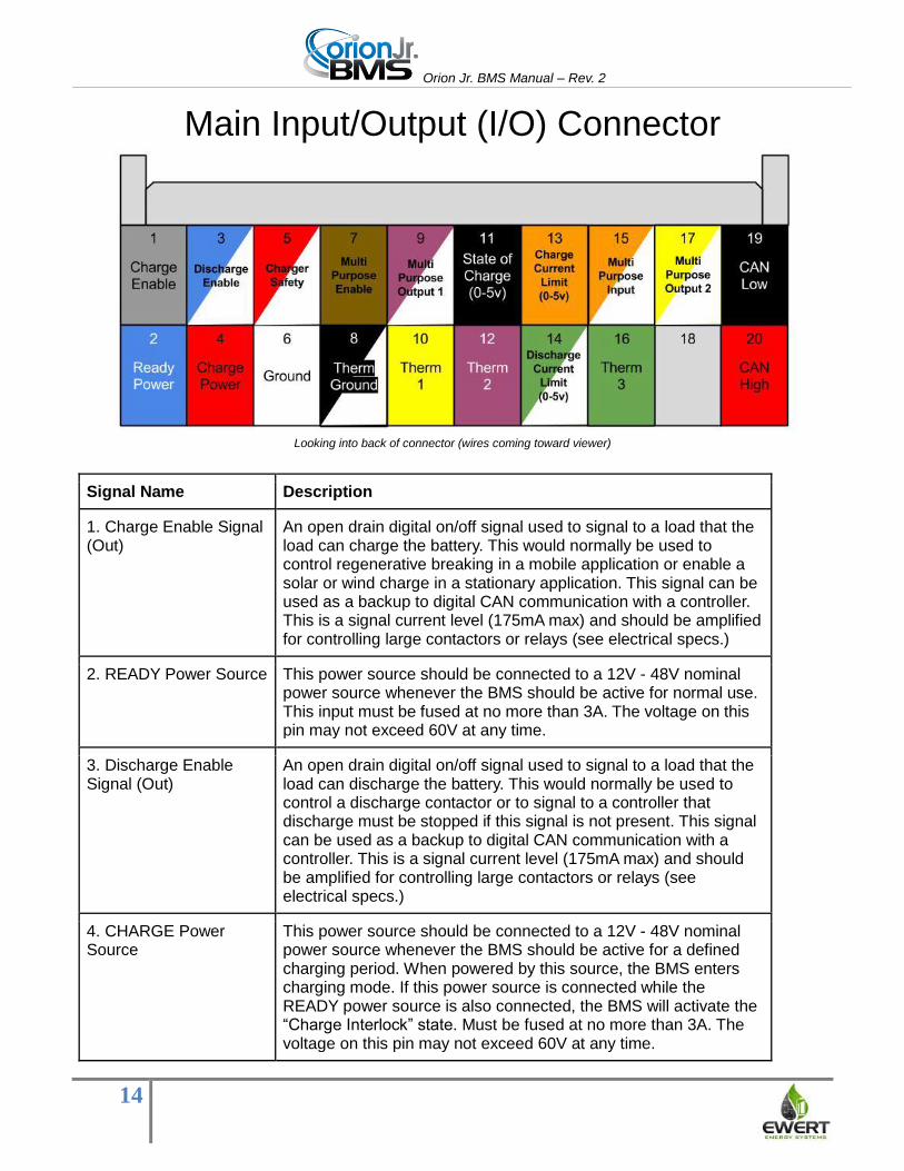
Main Input/Output (I/O) Connector
Looking into back of connector (wires coming toward viewer)
Signal Name Description
1. Charge Enable Signal (Out)
An open drain digital on/off signal used to signal to a load that the load can charge the battery. This would normally be used to control regenerative breaking in a mobile application or enable a solar or wind charge in a stationary application. This signal can be used as a backup to digital CAN communication with a controller. This is a signal current level (175mA max) and should be amplified for controlling large contactors or relays (see electrical specs.)
2. READY Power Source This power source should be connected to a 12V - 48V nominal power source whenever the BMS should be active for normal use. This input must be fused at no more than 3A. The voltage on this pin may not exceed 60V at any time.
3. Discharge Enable Signal (Out)
An open drain digital on/off signal used to signal to a load that the load can discharge the battery. This would normally be used to control a discharge contactor or to signal to a controller that discharge must be stopped if this signal is not present. This signal can be used as a backup to digital CAN communication with a controller. This is a signal current level (175mA max) and should be amplified for controlling large contactors or relays (see electrical specs.)
4. CHARGE Power Source
This power source should be connected to a 12V - 48V nominal power source whenever the BMS should be active for a defined charging period. When powered by this source, the BMS enters charging mode. If this power source is connected while the READY power source is also connected, the BMS will activate the “Charge Interlock” state. Must be fused at no more than 3A. The voltage on this pin may not exceed 60V at any time.

Orion Jr. BMS Manual – Rev. 2
15
5. Charge Safety Signal (Out)
An open drain digital on/off signal used as a safety switch for a charger. This signal is normally connected to the charger or connected to a relay which enables AC power to the charger such that the lack of this signal will cause the charger to be inactive. This is a signal current level (175mA max) and should be amplified for controlling large contactors or relays (see electrical specs.)
6. Power Ground This is the ground for the supply power for the BMS. Both power sources (READY and CHARGE) share this ground, and grounds for these power sources must be bonded together externally.
7. Multi Purpose Enable An open drain digital on/off signal with configurable behavior. This is a signal current level (175mA max) and should be amplified for controlling large contactors or relays (see electrical specs.) Please see the software manual for a complete list of available functions. This output is watchdog backed and will turn off when certain faults occur, regardless of programmed settings.
8. Thermistor Ground One leg of each of the two thermistors should be grounded to this ground. Both thermistors share this ground return.
9. Multi Purpose Output 1
The behavior of this multi-purpose output is configured in software for additional functionality. This output is often used to drive an LED to indicate the presence of error codes, but can also be used as a CAN controlled output as well as other functions. Please see the software manual for a complete list of available functions. This output is NOT watchdog backed and may remain on when certain faults occur.
10. Thermistor 1 12. Thermistor 2 16. Thermistor 3
One leg of each of the thermistors should be connected to the respective thermistor pin. These pins connect to 10K NTC thermistors.
Analog 5v Outputs: 11. State of Charge 13. Charge Current Limit 14. Discharge Current
0-5V analog outputs that represent charge current limit, discharge current limit, and state of charge.
15. Multi Purpose Input This is an input signal that can have multiple different input functions such as redundant keep-awake power signals, clearing DTC fault codes and other functions. Please see the software manual for a complete list of available functions. The voltage range for this pin is 9-60V.
17, Multi Purpose Output 2
The behavior of this multi-purpose output is configured in software for additional functionality. Please see the software manual for a complete list of available functions. This output is NOT watchdog backed and may remain on when certain faults occur.
19. CAN_L 20. CAN_H
CAN interface with high and low signal lines. Only available on units ordered with CANBUS. Unless special ordered, the BMS unit has a termination resistor installed inside the unit (120 ohm).

Orion Jr. BMS Manual – Rev. 2
16
Wiring Main Connector
Fusing Important: As with all electrical devices, all wires connected to the Orion Jr. BMS unit must be current
limited at their source. Any circuit connecting to the BMS must be current limited with an appropriately
sized fuse (or other current limiting device) to prevent overloading wires in the event of a short. The
external fuse must be sized properly to protect the conductors and must specifically have a DC
voltage rating of no less than the maximum possible working voltage and an appropriate DC
interrupting current rating for the application.
The maximum fuse size permitted for the CHARGE or READY power, any of the open drain output
pins, or multipurpose input pins is 3A, but smaller fuses may be used.
Two diagrams showing fuse placement.
Power Supplies Operating power is supplied to the Orion Jr. by two separate power sources. The power supplies will
not backfeed each other due to internal diodes. The Orion Jr. consumes approximately 1-2 watts for
operating current. Actual current varies depending on supply voltage and may be higher if additional
devices are connected to the Orion Jr. Operating current will be drawn from the higher voltage source if
both sources are on at the same time.
The Orion Jr. units are designed to be powered either from an auxiliary power source or from the pack
voltage and operate on 12-48 volts nominal for operating power. Voltages between 9V and 60V are
acceptable for continuous operation. Voltages below 9V may cause the BMS to turn off, and voltages
over 60V will damage the BMS unit. The supply voltage may not exceed 60V at any time.

Orion Jr. BMS Manual – Rev. 2
17
If pack voltage is used to supply operating current to the Orion Jr. unit, care must be taken as
other I/O pins, including the thermistor inputs on the Main I/O connector, are not electrically
isolated from the supply power.
Revision C units have been tested to withstand limited damaging transients on the CHARGE and
READY power inputs of up to +/- 300 V, 2mS duration with 5 ohm source impedance as defined in
pulse 1 of 1SO 7637-2 (open drain outputs have been tested to withstand transients up to +/-200V,
0.05mS duration with 2 ohm source impedance as defined by ISO 7637-2). If transients beyond these
rating are expected on any input to the BMS including the ready or charge power sources, external
transient protection must be supplied (Note: very strong transients may also damage other equipment
or even the battery cells themselves).
If the BMS is powered directly from the battery pack it is protecting, care must also be taken
such that the operating current powering the BMS does not over-discharge the battery in the
event the battery is not charged for an extended period of time. Over-discharge of a battery pack
may destroy the entire battery pack in one single event, so this is essential. The Orion Jr. unit has an
optional low-power shutdown mode which causes the BMS to shutdown and draw about 0.1 watts
when the voltage of the lowest cell drops below a certain voltage. This optional low power shutdown
feature must be enabled in software (disabled by default). On revision A and B units, it may cause the
BMS to lock in the “off” state for up to 5 minutes when triggered, even after power is disconnected. This
feature will slow down discharge, but it will NOT fully protect the battery as the unit will still
draw about 0.1 watts or up to about 20mA from the battery pack even when in shutdown and
this will eventually drain the battery pack. Lithium-ion cells can be destroyed in one cycle when
over-discharged.
Ready Power Source: This is the primary power source for the Orion Jr. BMS unit. This power source
can be thought of as the “ignition” power source when the BMS is used in mobile applications. When
power is present at this source, the BMS will allow both normal charge and discharge. When powered
only by this power source (i.e. charge power is not present), the BMS will not engage the charger safety
output (usually used to control a battery charger) and will not allow cell balancing.
Charge Power Source: This power source should be energized when the battery is in a defined
charging phase such as being fully charged by an AC battery charger. When power is present at this
pin, the BMS will enter charging mode, which enables cell balancing and enables the charger safety
signal output. For most applications, this is used when the BMS is in a defined charging phase from AC
power. Because of this, CHARGE power is normally provided by a small AC / DC power adapter
powered off the mains.
The BMS will fully operate with both the charge and ready power sources powered at the same time. If
both CHARGE and READY power sources are energized at the same time, the BMS will allow normal
charge and discharge and will also enable the charger safety output and balancing.

Orion Jr. BMS Manual – Rev. 2
18
LED Status Light The LED light on the BMS unit indicates its status: A green light indicates that the unit is powered and
that there are no errors present. A red light indicates that the unit is powered, but errors are present. If
the light is not lit, the unit is not receiving power or has entered into a low power shutdown. If a unit has
firmware revision 2.0.1 or newer (only available for rev C), a rapidly blinking red light indicates that the
unit is detecting a voltage greater than 5v on one of the cell taps, which may be damaging the unit.
Immediately disconnect the unit if the light begins rapidly blinking red. Note: the absence of the rapid
red LED does not indicated wiring is necessarily correct!
Wiring CAN interfaces This option is only available if the BMS unit is ordered with a CANBUS interface. The CANBUS
interfaces can be configured to run at 125, 250, 500 or 1000 Kbps. CAN interfaces are differential mode
buses and require twisted pair wire (2 wires) to communicate. For best operation, shielded twisted pair
wire should be used for protection against electrical noise immunity, particularly when used in noisy
environments. Shields should only be connected in one location to prevent ground loops. While it is
necessary for the twisted pair CAN wires to be outside of the shield for a short distance at any
connectors, the amount of non shielded, non-twisted wire should be kept as short as possible, ideally
less than 2-3 inches, especially in high noise environments.
Controller Area Networks (CAN) require exactly two 120 ohm termination resistors on the two physical
ends of the bus to operate properly. Unless specifically ordered without, the Orion Jr. BMS contains one
120 ohm termination resistor inside the unit. A CANBUS can have many nodes attached to a single
bus. If only two nodes are attached, they should be at the physical ends of the cable with a termination
resistor as close to each end as possible. If additional nodes are used, they should “T” off the main
wire. While the entire CANBUS cable can be very long (up to 30 meters for 1mpbs, 100 meters for
500kbps, or 500 meters for 125kbps), the taps off the main wire for additional nodes should be kept
less than about 3.5 feet or 1 meter off the main cable. If improperly wired (i.e. only one termination
resistor on the bus or long taps off the main cable), the bus sometimes may appear to work, but may
then fail or suffer reliability problems at a later time when exposed to more significant noise. The bus
must be properly terminated even if it appears to work with just one termination resistor!
Diagram of a multi-node CANBUS with 120 ohm termination resistors at the ends
After wiring the CAN interfaces, verify proper termination by using an ohm-meter to check the
resistance between CAN_H and CAN_L. In order to verify the resistance, all power must be removed
from all devices on the CANBUS. The total resistance should measure 60 ohms (two 120 ohm resistors
in parallel = 60 ohms.)

Orion Jr. BMS Manual – Rev. 2
19
Wiring digital signal outputs The Orion Jr. has either 5 (revisions A & B) or 6 (revision C) signal level digital I/O outputs - Charge
Enable, Discharge Enable, Charger Safety, Multi Purpose Enable, Multi Purpose Output 1, and Multi
Purpose Output 2 (revision C only). These outputs are open drain outputs which means that they do not
source any current or voltage, but rather pull down to ground and sink current when they are turned on.
While this may seem like an odd way to interface with the BMS, this method provides greater flexibility
and can interface with a wide range of applications using different voltages up to 24V nominal / 30V
maximum for revision A units and 48V nominal / 60V maximum for revision B & C units. These
outputs pull low when they are “on” and cannot be inverted in software for safety reasons. This is done
so that if the BMS connecter were to become disconnected, the outputs would fail “off” rather than “on”.
For safety reasons, the Charge Enable, Discharge Enable, Charger Safety and Multi Purpose Enable
outputs feature an analog watchdog circuit which turns these four outputs off in the event of a
processor malfunction, adding an extra layer of safety. The Multi Purpose Outputs 1 and 2 do not have
the watchdog feature as it is not designed to control charge or discharge current.
Important: An external fuse rated 3A or less rated for at least the full DC working voltage with a suitable
interrupting current rating must be installed at the voltage source to protect the wiring to any open drain
output or relay controlled by the BMS. Fuses must have a voltage rating that exceeds the maximum
possible working voltage and must be rated with a sufficient interrupting current rating.
Please note that the output of an open drain cannot be directly measured with a multimeter as they do
not source voltage. Please see below for more information on testing the outputs.
Simplified internal schematic for signal outputs
Charge Enable Output (pin 1) - This pin is enabled in both READY and CHARGE modes and is
turned on (pulled low) as soon as the BMS has gone through self checks and determined that the
battery is able to be charged. This output will turn off (float high) if the BMS determines that the battery
can no longer accept a charge or if the maximum charge amperage is exceeded. This output can be
turned back on again automatically when certain criteria set in the software are met. If the BMS turns
this output off (and if the charger safety output is also off), but still measures current flowing into the
battery pack afterwards, a critical error will be set on the BMS resulting in the disabling of all charge
and discharge until the BMS has been reset as a safety feature. Please see the software manual for
more details on how the BMS determines when this pin is on or off.
Important: In addition to using this output, any charge source should be set such that it will shut off in
the event the maximum pack voltage is reached as a secondary precaution against overcharge. While
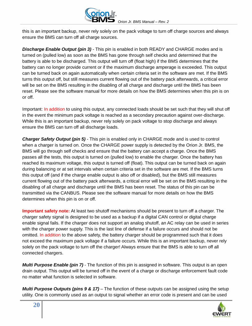
Orion Jr. BMS Manual – Rev. 2
20
this is an important backup, never rely solely on the pack voltage to turn off charge sources and always
ensure the BMS can turn off all charge sources.
Discharge Enable Output (pin 3) - This pin is enabled in both READY and CHARGE modes and is
turned on (pulled low) as soon as the BMS has gone through self checks and determined that the
battery is able to be discharged. This output will turn off (float high) if the BMS determines that the
battery can no longer provide current or if the maximum discharge amperage is exceeded. This output
can be turned back on again automatically when certain criteria set in the software are met. If the BMS
turns this output off, but still measures current flowing out of the battery pack afterwards, a critical error
will be set on the BMS resulting in the disabling of all charge and discharge until the BMS has been
reset. Please see the software manual for more details on how the BMS determines when this pin is on
or off.
Important: In addition to using this output, any connected loads should be set such that they will shut off
in the event the minimum pack voltage is reached as a secondary precaution against over-discharge.
While this is an important backup, never rely solely on pack voltage to stop discharge and always
ensure the BMS can turn off all discharge loads.
Charger Safety Output (pin 5) - This pin is enabled only in CHARGE mode and is used to control
when a charger is turned on. Once the CHARGE power supply is detected by the Orion Jr. BMS, the
BMS will go through self checks and ensure that the battery can accept a charge. Once the BMS
passes all the tests, this output is turned on (pulled low) to enable the charger. Once the battery has
reached its maximum voltage, this output is turned off (float). This output can be turned back on again
during balancing or at set intervals when certain criteria set in the software are met. If the BMS turns
this output off (and if the charge enable output is also off or disabled), but the BMS still measures
current flowing out of the battery pack afterwards, a critical error will be set on the BMS resulting in the
disabling of all charge and discharge until the BMS has been reset. The status of this pin can be
transmitted via the CANBUS. Please see the software manual for more details on how the BMS
determines when this pin is on or off.
Important safety note: At least two shutoff mechanisms should be present to turn off a charger. The
charger safety signal is designed to be used as a backup if a digital CAN control or digital charge
enable signal fails. If the charger does not support an analog shutoff, an AC relay can be used in series
with the charger power supply. This is the last line of defense if a failure occurs and should not be
omitted. In addition to the above safety, the battery charger should be programmed such that it does
not exceed the maximum pack voltage if a failure occurs. While this is an important backup, never rely
solely on the pack voltage to turn off the charger! Always ensure that the BMS is able to turn off all
connected chargers.
Multi Purpose Enable (pin 7) - The function of this pin is assigned in software. This output is an open
drain output. This output will be turned off in the event of a charge or discharge enforcement fault code
no matter what function is selected in software.
Multi Purpose Outputs (pins 9 & 17) – The function of these outputs can be assigned using the setup
utility. One is commonly used as an output to signal whether an error code is present and can be used

Orion Jr. BMS Manual – Rev. 2
21
to drive an error LED, such as the LED on the Orion Jr. BMS basic display board. These outputs are
both open drain outputs which pull down to ground when “ON.” It is important to note that these two
outputs are not watchdog backed and will not turn off in the event of certain faults. These two outputs
should not be used as the sole mechanism to control charge sources or discharge loads.
Important notes about digital signal outputs: All of these open drain outputs are capable of directly
controlling small relay coils under 175mA and a maximum voltage up to 24V / 30 V maximum for
revision A units and 48V nominal / 60V maximum for revision B and C units. The BMS has internal
protection from the back EMF generated by the relay coils, and additional clamping diodes can be
added for additional protection if desired. Damage can occur to the BMS if currents larger than 175MA
are present, even for short inrush periods. This can lead to undefined behavior of these outputs,
including the shorting of the output. These outputs should not be used to directly drive large contactors.
Some large contactors have a DC:DC converter attached to reduce average power consumption, but
they still require a large inrush current to turn on initially. This large inrush current can damage the BMS
units. These outputs must be amplified if used with large contactors (amplification methods listed
below). The Orion Jr. units have resettable internal fuses on these outputs, but these over-current
protection devices can become damaged from repeated over-current or sustained over-current events.
Always monitor the first charge and discharge cycle manually and ensure that the BMS has
proper control over the loads and the sources of current to and from the battery. If you receive a
charge, discharge, or charger safety relay fault error, immediately investigate to ensure over-
charging or over-discharging is not occurring.
Care must be taken to avoid differences in ground potentials between the BMS unit and other parts of
the application. A difference in ground potentials can cause the digital signal outputs to sink current due
to internal protection diodes (see schematics above). Care must also be taken to ensure that the
voltage on these pins never exceeds 60V. While voltages above 60V are never permitted on these pins,
a voltage exceed 70V will damage the unit and cause these pins to short on “on.”
If additional power is needed or if galvanic isolation is required, the digital signal outputs can be used to
drive opto-isolators or other loads. Below are a sample schematic for connecting a relay with a coil less
than 175mA and a sample with an opto-isolator. Please note that the below schematics are for general
reference and the suitability of each circuit must be determined by the user.
A sample schematic for connecting the open drain outputs with a relay. Note: For Rev A units, the maximum switching voltage is 24V.

Orion Jr. BMS Manual – Rev. 2
22
A sample schematic for connecting the open drain outputs with an opto-isolator (resistor values must be calculated based on voltage and opto-
isolator requirements). Note: For Rev A units, the maximum switching voltage is 24V.
If the signals will be used to drive relays with coils larger than 175mA, contactors, or other loads, an
amplification method must be used so that the BMS does not sink more than the maximum allowable
current. A common method for this is to use a MOSFET to amplify the signal to provide power to a
larger relay or contactor. A schematic is shown below for this method.
Schematic showing a P-channel MOSFET used to amplify the open drain output. Note: For Rev A units, the maximum switching voltage is
24V.
Another method is to use a smaller relay to turn on power for the larger relay/contactor. A schematic for
this is shown below.

Orion Jr. BMS Manual – Rev. 2
23
Checking open drain outputs Open drain outputs will read zero volts on a voltmeter whether or not they are on since they sink current
rather than source it. A simple method for testing the outputs is to connect an LED or small light bulb
(under 100mA) between the output pin and +12v (or any voltage between 5V and 24V for Rev A and 48
V for Rev B.) If an LED is used, a series resistor (often between 330 ohm and 1k ohm) must be used to
limit current through the diode. When the output is on, the LED or bulb will illuminate. A schematic for
this is pictured below.
Wiring the multipurpose input The multipurpose input has a user selectable function and can be used for functions such as clearing
fault codes or indicating a certain status to the BMS. This input is present only on Rev. B & C units. A
voltage of 9 – 60V may be applied to this pin to indicate an “on” status. The voltage of this pin may not
exceed 60V at any point and a voltage below 9V may cause the status of this pin to become undefined.
The voltage source used to generate the signal for this pin must be fused at the source with a fuse no
larger than 3A. Since this input has a current draw of only a few mA, a significantly smaller fuse may be
used if the fuse is not shared with other circuits. Fuses must be rated for the full DC working voltage
and have a suitable interrupting current rating for the application.
Wiring the analog 0-5V outputs The Orion Jr. is equipped with three analog 0 to 5V voltage outputs designed to aid in integrating the
Orion Jr. with non-digital applications including voltage based displays. The outputs include pack state
of charge, charge current limit, and discharge current limit.
Each of the 0-5V analog voltage outputs can provide or sink up to 10mA of current. If more current is
necessary or if a different voltage range is necessary, an external analog buffer or op-amp must be
used to amplify the signal. The analog voltages are generated inside the Orion Jr. unit by a digital-to-
analog converter.
State of charge output (pin 11) - This output provides the calculated state of charge. 0V corresponds
to 0% state of charge and 5V corresponds to 100% state of charge. This output often is used to display
state of charge in applications where digital communications are not available.
Charge current limit (pin 13) - This output provides an analog representation of the maximum current
that the battery can accept at any given time. 0V corresponds to 0 amps and 5V corresponds to the
maximum amperage set in the profile for this specific output. Please see the software manual for
information on setting this maximum value.

Orion Jr. BMS Manual – Rev. 2
24
While this output can be reliably used to limit current, it should be used in conjunction with the charge
enable signal output (pin 10) which provides an analog watchdog shutoff circuit. Although unlikely, it is
possible for the digital-to-analog converter to fail, leaving the voltage in an undefined state.
Discharge current limit (pin 14) - This output provides an analog representation of the maximum
current that the battery can discharge at any given time. 0V corresponds to 0 amps and 5V
corresponds to the maximum amperage set in the profile for this specific output. Please see the
software manual for information on setting this maximum value.
While this output can be reliably used to limit current, it should be used in conjunction with the
discharge enable signal output (pin 3) which provides an analog watchdog shutoff circuit. Although
unlikely, it is possible for the digital-to-analog converter to fail, leaving the voltage in an undefined state.
Thermistors (Pins 10, 12, 16, and 8) The Orion Jr. main unit can have up to two (revision A & B) or three (revision C) thermistors directly
connected to the unit. These thermistors are designed to provide the BMS with a representative idea of
the pack temperature. The thermistors should be spread throughout the battery pack in a manner which
provides the most representative temperatures possible. If the battery pack is split into multiple physical
locations, at least one thermistor should be placed in each physical location. If the battery pack is in
one physical location, sensors should be scattered through different areas of the pack such as the
middle and outer portions of the pack.
Some applications may require the measurement of each individual cell temperature while
representative temperature readings are suitable for others. It is the integrator’s responsibility to
determine the necessary number of temperature monitors. If monitoring more temperatures is
necessary, an external thermistor expansion module is available which can monitor up to 80 additional
thermistors.
The thermistors are 10K NTC thermistors with a B25/50 value of 3380K. Other B values can be used
through the use of an external thermistor expansion module. Custom configurations of the main Orion
Jr. unit for B values may be available for high volume applications requiring a different B value. One
end of the thermistor is connected to the appropriate thermistor pin and the other is grounded to the
thermistor ground pin. As thermistors are resistive, polarity does not matter.
Thermistors can be attached to the battery cells in different ways depending on the type of cell. The
thermistors sold with the Orion Jr. have epoxy coated beads at the ends. They can be taped or glued to
cells. Some thermistors are attached to ring terminals and can be screwed onto battery terminals. Care
must be taken if the thermistors are attached to ring terminals to ensure that they have
sufficient electrical isolation from the battery pack. The thermistor measurement pins are NOT
electrically isolated from any other pin on the Main I/O connector, and a breakdown in isolation
may cause a short! Insufficient isolation can cause shorts outside the BMS and/or catastrophic
damage to the BMS unit. Fuses to guard against shorts on the thermistors may be necessary in certain
applications.

Orion Jr. BMS Manual – Rev. 2
25
Wiring Voltage Taps
READ THIS ENTIRE SECTION BEFORE WIRING. Several precautions need to be taken for the BMS
to function properly, accurately, and safely. While the Orion Jr. does not require the use of an in-pack
safety disconnect or fuse, if a safety disconnect or fuse is used, they must be wired in certain
locations. All battery packs must be suitably protected against over-current. Please see “Safety
Disconnect and Fuse Locations” for more information.
The Orion Jr. BMS is designed to manage as many as 16 cells, up to a maximum possible voltage of
60V DC, whichever is lower. For the purpose of this document, a “cell” refers to one or more cells
directly paralleled together. Below is the standard wiring diagram for cell taps. One cell tap is
provided for each cell with one negative tap for each group of 12 cells (in this case 1- and 13-). Cells
are numbered from the lowest stack potential to the highest stack potential (starting at the pack
negative and working up in number towards pack positive.)
The Orion Jr. unit can be used to monitor between 1 and 16 cells in series, with the total pack voltage
not to exceed 60V at any time.
Looking into back of connector (wires coming towards the viewer)

Orion Jr. BMS Manual – Rev. 2
26
Wiring - Full 16 Cells
The above image is standard wiring when used with 16 cells.
Rules for fewer than sixteen cells
● If fewer than twelve cells are populated in group 1 or fewer than four cells in group 2,
unpopulated cells in that group must all be connected to the positive terminal of the highest
potential cell in that group. For example, if only six cells are populated in group 1, taps 6 - 12
are all connected to the positive tap on cell 6.*
● If no cells in the 2nd group (cells 13-16) are used, wires 13-16 (including 13-) should be left
disconnected.
● In all cases, the Pack+ wire will be connected to the positive most terminal of the positive most
cell.
*In this example, cell tap positions 6-11 could be combined into a single wire that runs to the terminal to
reduce the number of wires entering the battery area.

Orion Jr. BMS Manual – Rev. 2
27
Wiring Example - 15 Cells
Wiring example for 15 cells in series. Tap 16 and 15 both attach to positive terminal on cell 15.
Wiring Example - 8 Cells
Wiring example for eight cells in series. Taps 8-12 all attach to the positive terminal on cell 8.
Orion Jr. BMS Manual – Rev. 2
28
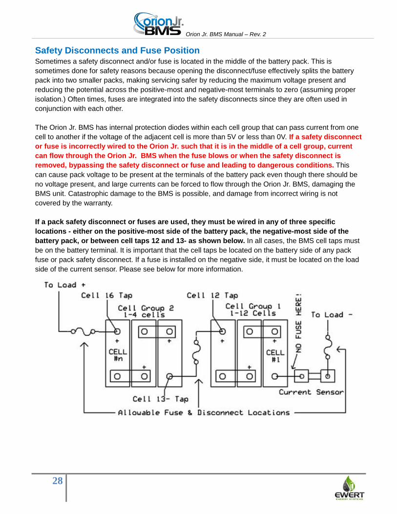
Safety Disconnects and Fuse Position Sometimes a safety disconnect and/or fuse is located in the middle of the battery pack. This is
sometimes done for safety reasons because opening the disconnect/fuse effectively splits the battery
pack into two smaller packs, making servicing safer by reducing the maximum voltage present and
reducing the potential across the positive-most and negative-most terminals to zero (assuming proper
isolation.) Often times, fuses are integrated into the safety disconnects since they are often used in
conjunction with each other.
The Orion Jr. BMS has internal protection diodes within each cell group that can pass current from one
cell to another if the voltage of the adjacent cell is more than 5V or less than 0V. If a safety disconnect
or fuse is incorrectly wired to the Orion Jr. such that it is in the middle of a cell group, current
can flow through the Orion Jr. BMS when the fuse blows or when the safety disconnect is
removed, bypassing the safety disconnect or fuse and leading to dangerous conditions. This
can cause pack voltage to be present at the terminals of the battery pack even though there should be
no voltage present, and large currents can be forced to flow through the Orion Jr. BMS, damaging the
BMS unit. Catastrophic damage to the BMS is possible, and damage from incorrect wiring is not
covered by the warranty.
If a pack safety disconnect or fuses are used, they must be wired in any of three specific
locations - either on the positive-most side of the battery pack, the negative-most side of the
battery pack, or between cell taps 12 and 13- as shown below. In all cases, the BMS cell taps must
be on the battery terminal. It is important that the cell taps be located on the battery side of any pack
fuse or pack safety disconnect. If a fuse is installed on the negative side, it must be located on the load
side of the current sensor. Please see below for more information.

Orion Jr. BMS Manual – Rev. 2
29
Current Sensor
The above image shows current sensor wiring.
The Orion Jr. BMS uses an inline shunt resistor to measure current. When current runs through
the shunt resistor, a small voltage drop is produced. The BMS measures this small voltage drop to
calculate the current flow.
Because the shunt is in-line and is electrically connected to the battery pack, the shunt resistor
may ONLY be electrically wired between the negative terminal of the negative-most cell and the
load negative. While it is permissible for cable to be between the negative terminal and the shunt
resistor, no fuses, safety disconnects, contactors, or other disconnecting means may be between the
negative terminal and the shunt current sensor as this may cause full stack potential to be applied to
the current sensor monitoring circuit, damaging the BMS. Always unplug the BMS before making any
wiring changes to any battery wiring. All current, including the charger, must flow through the shunt
current sensor to be measured (as pictured above).
While the direction of the current sensor shunt itself does not matter, the connection of the
current sensor + and current sensor - wires does matter. The current sensor - wire should be on the
side of the current sensor connected to the negative terminal of the battery and the current sensor +
side should be connected to the load side of the sensor. The above diagram shows the standard
orientation of the current sensors, but if the wiring is backwards, the current sensor direction can be
inverted in the Orion Jr. profile using the utility software. In the initial setup of the unit, the direction of
current should be verified by using the BMS utility to ensure proper configuration. Test the wiring of the
voltage taps and current sensor wires before connecting to the BMS.
The Orion Jr. units are designed to be used with 50mV shunts. 75mV shunts can also be used,
but the current measurement is limited by the equivalent 50mV rating (⅔ of the 75mV rating.) For
example, a 200A 75mV shunt is the equivalent of a 150A 50mV shunt. Either shunt may be used, but

Orion Jr. BMS Manual – Rev. 2
30
the maximum amperage in either case is 150A. The table below lists currently supported shunt sizes.
Support for additional sizes may be available on request.
Max Current 50mV Shunt 75mV Shunt Equivalent
20A 20A / 50mV 30A / 75mV
50A 50A / 50mV 75A / 75mV
100A 100A / 50mV 150A / 75mV
150A 150A / 50mV 200A / 75mV
200A 200A / 50mV 300A / 75mV
333A N/A 500A / 75mV
400A 400A / 50mV 600A / 75mV
500A 500A / 50mV 750A / 75mV
600A* 600A / 50mV 900A / 75mV
1000A* 1000A / 50mV 1500A / 75mV
* Current sensors sized above 500 A are supported, but will have a reduced accuracy and resolution.
Orion Jr. BMS Manual – Rev. 2
31
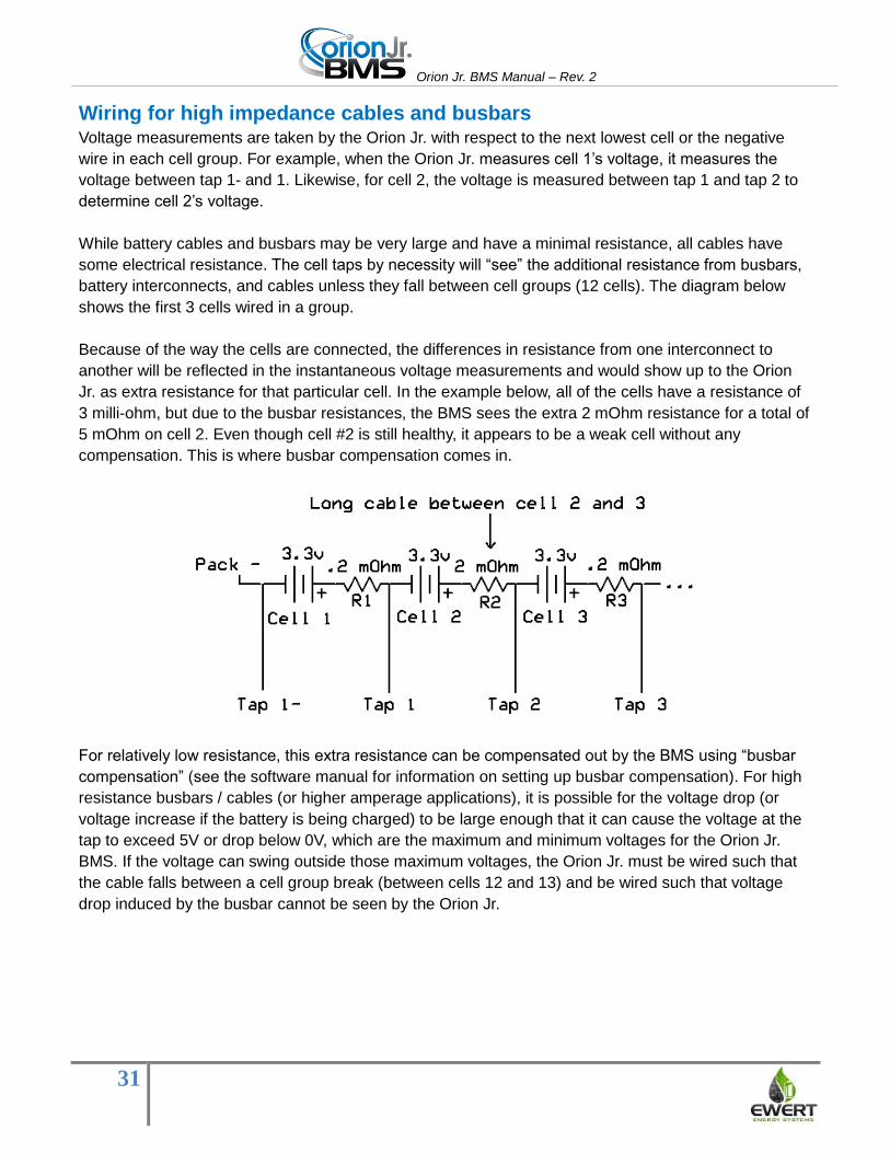
Wiring for high impedance cables and busbars Voltage measurements are taken by the Orion Jr. with respect to the next lowest cell or the negative
wire in each cell group. For example, when the Orion Jr. measures cell 1’s voltage, it measures the
voltage between tap 1- and 1. Likewise, for cell 2, the voltage is measured between tap 1 and tap 2 to
determine cell 2’s voltage.
While battery cables and busbars may be very large and have a minimal resistance, all cables have
some electrical resistance. The cell taps by necessity will “see” the additional resistance from busbars,
battery interconnects, and cables unless they fall between cell groups (12 cells). The diagram below
shows the first 3 cells wired in a group.
Because of the way the cells are connected, the differences in resistance from one interconnect to
another will be reflected in the instantaneous voltage measurements and would show up to the Orion
Jr. as extra resistance for that particular cell. In the example below, all of the cells have a resistance of
3 milli-ohm, but due to the busbar resistances, the BMS sees the extra 2 mOhm resistance for a total of
5 mOhm on cell 2. Even though cell #2 is still healthy, it appears to be a weak cell without any
compensation. This is where busbar compensation comes in.
For relatively low resistance, this extra resistance can be compensated out by the BMS using “busbar
compensation” (see the software manual for information on setting up busbar compensation). For high
resistance busbars / cables (or higher amperage applications), it is possible for the voltage drop (or
voltage increase if the battery is being charged) to be large enough that it can cause the voltage at the
tap to exceed 5V or drop below 0V, which are the maximum and minimum voltages for the Orion Jr.
BMS. If the voltage can swing outside those maximum voltages, the Orion Jr. must be wired such that
the cable falls between a cell group break (between cells 12 and 13) and be wired such that voltage
drop induced by the busbar cannot be seen by the Orion Jr.

Orion Jr. BMS Manual – Rev. 2
32
Voltage drop under load from an uncompensated high impedance busbar (blue)
Maximum voltage swing can be calculated if the maximum cell voltage, resistance of the busbar / cable,
and maximum amperage are known using the following formulas. Please keep in mind that the
resistance of the busbar or cable must include the resistance of the terminal and any crimps. Headroom
must be left for possible small increases in resistance due to eventual corrosion, etc.
Peak_voltage = Vmax_cell + (Rbusbar * Imax_charge) (Peak_voltage must be < 5v)
Lowest_voltage = Vmin_cell - (Rbusbar * Imax_discharge) (Lowest voltage must be >0v)
In the above example, if the cells have a maximum voltage of 3.65v (Vmax_cell) and a minimum of 2v
(Vmin_cell) and a maximum amperage of +/-200A (Imax_charge and Imax_discharge), the peak
voltage with the given 2 mOhm cable would be 4.05v and the lowest voltage 1.6v. These voltages are
within the limits and busbar compensation could be used.
Skin effect issues due to AC currents The vast majority of motor controllers available on the market provide some amount of filtering on the
DC bus in order to limit radiated and conducted emissions. While most motor controllers generate high
levels of noise, the noise generally does not lead to a significant AC component on the DC bus. A small
minority of motor controllers lack adequate internal bulk capacitance and filtering and actually produce
a high frequency AC component on the DC bus.

Orion Jr. BMS Manual – Rev. 2
33
The Orion Jr. is extremely resistant to electrical noise (EMI) and has been tested in real world situations
to operate successfully with this excessive noise. However, a strong high frequency AC component can
create a “Skin Effect” on the cables connecting the batteries. Skin effect occurs when eddy currents
form within the cables, causing only the outside portion of the wire to carry current and effectively
increasing the resistance of the wire.
Although the Orion Jr. has been tested extensively to operate and measure voltages properly in these
extremely harsh noise environments, the BMS may correctly measure unpredictably changing
resistance values since the effective resistance of the cable is changing considerably with respect to
amplitude and frequency. The Orion Jr. BMS bases many calculations on the measured resistance of
the cells, including open cell voltage calculations which are used for determining maximum current
limits and determining when cells are weak. If a significant skin effect is present, it can introduce
inaccuracies with some calculations even though the Orion Jr. BMS continues to operate.
The overwhelming majority of motor controllers have adequate filtering to reduce conducted emissions
to levels that prevent a skin effect from forming. For the small number that do not, the skin effect can be
mitigated somewhat by using suitable rectangular busbars or straps rather than round cables. In an
environment where a skin effect forms, any round cables should be wired such that they fall between
cell groups since the BMS cannot effectively compensate them out. Preferably, it may be possible to
add external filtering to the motor controller to suppress the conducted emissions generated by the
motor controller to a tolerable level. Extremely high amounts of AC noise can also cause back EMF
from stray inductance in the cabling. If this occurs, the emissions will need to be limited to a safe level.
Transients Transients on the battery pack must be limited to reasonable levels. This is important both for the
protection of the BMS and the protection of the attached lithium cells. Lithium cells exposed to extreme
transients may short and enter thermal runaway. Extreme transients are often generated by the
combination of rapid changes in current and stray inductance. These usually occur when bulk
capacitors in motor controllers or chargers are switched into circuit or by other rapid changes in current
such as from a blowing fuse or sudden connection of current. Transients due to normal switching from
contactors can be limited by using proper pre-charge circuits and limiting slew rates for motor
controllers. The use of multiple chargers with series diodes is not recommended for use with the Orion
Jr. BMS as these configurations can cause damaging transients.
Excessive transients may cause damage to the Orion Jr. BMS unit or to connected lithium ion cells. In
the event that excessive transients have occurred, the Orion Jr. unit and lithium cells should be
immediately inspected or tested for damage as damage can lead to safety risks.
If a unit has been damaged by transients, it must be disconnected immediately from service and
repaired or replaced. Never continue to use a damaged unit.

Orion Jr. BMS Manual – Rev. 2
34
Wiring Errors Wiring errors can cause serious damage to the Orion Jr. BMS that is not covered under warranty. The
Orion Jr. has internal fuses on each cell tap wire to protect the BMS and connected wiring from
excessive currents. The Orion Jr. is designed to withstand certain minor wiring errors such as
accidentally swapping the order of 2 cells or even wiring cells in the reverse order. The internal fuses
are designed to blow with voltages more than +/- 24V for Rev A units, +/-48V for Rev B units, and +/-
60V for revision C units (though there are some rare situations where fuses can still blow at lower
voltages and some situations where they won’t blow until voltages are higher). The Orion Jr. can
withstand wiring errors only for a short period of time and repeated or extended exposure to wiring
errors may cause permanent damage which may alter the accuracy of the voltage measurements. If an
Orion Jr. unit is wired improperly, small currents may flow through the BMS, and the BMS unit
may heat. An incorrectly wired unit should not be left connected to the battery pack for more
than 5 minutes as it will eventually drain and can destroy cells connected to it. If there is question
as to whether the harnesses are wired properly, do not leave them connected to a unit for any length of
time. The Orion Jr. units may report an “open wire fault,” “wiring fault,” or “low cell fault” if incorrectly
wired. Revision C units with firmware 2.0.2 or newer may also rapidly flash the red LED to indicate
incorrect wiring that is damaging the unit. The absence of a rapidly flashing red LED does not
necessarily indicate correct wiring. If the red LED begins to flash rapidly, immediately disconnect the
cell tap harness and inspect the wiring. If a unit has been damaged, do not continue to use the unit.
Voltage tap harness lengths Standard voltage wiring harnesses are available for the Orion Jr. in 6 foot lengths. The length of the tap
harness slightly affects the accuracy of the voltage readings by the Orion Jr. The length of cable does
not significantly alter the accuracy of the voltage measurement.

Orion Jr. BMS Manual – Rev. 2
35
Internal Isolation The Orion Jr. has nominal isolation between cell voltage tap sensors and the control electronics and
between cell groups 1 and 2 for functional purposes only.
Fuses on voltage tap wires The Orion Jr. BMS has internal fuses on each of the positive cell tap wires. While these fuses protect
the BMS, guard against excessive current flowing through the internal protection diodes, and are
designed to blow if the maximum voltages are exceeded, the internal BMS fuses do not protect
against two tap wires that short together outside the BMS, against shorts at the connector on the
BMS, or against excessively high cell tap voltages. While many major OEM vehicle manufacturers have
carefully calculated and rely upon the fusing characteristics of the cell tap wires, fuses are strongly
recommended as this technique requires much testing and engineering. Some applications will
require the use of fuses on the cell taps. It is the sole responsibility of the integrator to
determine if these external fuses are needed.
If external fuses are used, they should be kept as low resistance as possible with reason and rated no
larger than 3A. Fuses must always be rated for the maximum possible DC working voltage with a
suitable DC interrupting current rating. Certain electrical codes or regulations may dictate the maximum
fuse size, and it may be smaller than 3A depending on wire gauge and other considerations. Fuses
sometimes have relatively high resistance, and the additional resistance can reduce the accuracy of
monitoring the cells. Additionally, fuses may be necessary on thermistors to protect against a possible
short between a thermistor and a terminal of a battery. It is the sole responsibility of the integrator to
determine if fuses are necessary on the cell tap wires.
Physical routing and installation of wires The integrator is solely responsible for designing proper external wire routing, including the selection of
suitable wire types and selection of other external components including wire types and wire conduits.
For safety reasons, all external wires must be adequately protected from damage including abrasion
from rubbing, vibration, or sharp objects. The integrator must consider all possible environmental
aspects including, but not limited to, corrosion or loosening of joints or screws, galvanic reactions,
expansion and contraction of wires, busbars, and interconnects due to temperature, condensation, etc.
The integrator must also ensure the separation of components and wires from flammable materials.
The integrator is solely responsible for ensuring that the application complies with any applicable
codes, regulations, and standards.

Orion Jr. BMS Manual – Rev. 2
36
Verifying Cell Voltage Tap Wiring
The wiring must be verified prior to connecting any of the wiring harnesses to the Orion Jr. BMS.
Improper wiring can cause damage to the BMS unit, catastrophic failure, or even personal safety risks
depending on the extent of the wiring mistake.
The most important connector to verify is the cell voltage tap harness, which includes the current
sensor wires. There are two methods for doing this:
The first is the tap validation tool which is available for rental or purchase. The tool can be connected to
the wiring harness already connected to the battery pack and will verify that cells are wired in the
correct order and can detect most wiring mistakes. The validation tool is designed to withstand
incorrectly wired harnesses without damage. It is strongly recommended to use the validation tool
before plugging the harness into the Orion Jr. BMS as it is very easy to make an error wiring the
harness, and errors may not be obvious. Please refer to the cell tap validation tool manual for more
information on proper testing. While the tester can catch most wiring faults, it cannot detect all
intermittent and high impedance faults.
Wiring can also be verified by carefully using a multimeter, but the use of the tap validation tool is the
recommended method. Care must be taken not to short any pins with the multimeter. Personal
safety equipment including protective eye-wear and gloves and arc-flash resistant clothing
should be worn for protection in the event of an arc flash. In order to avoid two probes on the
connector, the negative probe should be attached to the negative most terminal of the negative most
cell in the pack rather than on the connector. Then, being careful not to short pins or touch the probe,
carefully measure each of the pins on the connector starting with the current sensor - and + wires and
the pin for 1-. The current sensor -, +, and the 1- pin should all read 0V since the negative probe of the
multimeter is connected to the same potential. Pin 1+ should read the voltage of the first cell (3.3V for
example), pin 2 should read the sum of the first two cells (6.6V for example), and so forth. The
connection for cell 12 and 13- should read the same voltage since they are connected to the same
potential.
When connecting the harness to the BMS for the first time, (after verifying correct wiring), first adjust
the cell population settings in the BMS software so the BMS is aware which cells it should be expecting
to see. Once you have uploaded the profile to the BMS (see the software manual for more information
on this), use the live cell voltages screen to verify that all cell voltages are reading correctly. Then verify
on the diagnostic trouble code screen that no “open wire faults,” “wiring faults,” or “low cell” faults are
present on the BMS. Open wire or wiring faults indicate that the BMS has detected a problem with the
cell tap wiring. If errors are found or if cell voltages are not matching properly, do not leave the
BMS connected to the pack for long periods of time as it may drain cells and cause damage to
them. If the BMS begins to rapidly flash the red LED (Rev C units only), immediately disconnect
the cell tap harness as this indicates that the BMS may be getting damaged by incorrect wiring.
Note that the absence of a rapidly flashing red LED does not necessarily indicate correct wiring

Orion Jr. BMS Manual – Rev. 2
37
Why Orion Jr. BMS Internal Fuses Blow
The Orion Jr. BMS has an internal fuse for each of the cell voltage tap wires. These fuses are designed
to blow in over-voltage and reverse-voltage conditions. Sufficient current to blow the fuses will only flow
through the tap wires during an over-voltage or reverse-voltage condition.
Below is a diagram showing a sample 48 cell battery pack connected to an Orion Jr. BMS unit. While
this example is a higher voltage than the Orion Jr. BMS can handle, the same principal applies. The
internal fuses and protection diodes inside the unit are depicted below. In the diagram, all cell tap
voltages are within 0 – 5 volts with respect to the next lower cell. As a result, none of the zener diodes
conduct and no significant current is flowing through the BMS. Since no current is flowing, all fuses
remain in a closed state.
What causes the fuses to blow? The only time the internal fuses on the tap wires will open is from an over-voltage or reverse-voltage
condition. When an over-voltage or reverse-voltage condition occurs, the zener diodes will begin to
conduct, causing current to flow through the tap wires and causing the fuses on the taps to blow. This is
necessary in order to protect the voltage measurement electronics from damage. Over-voltage and
reverse-voltage conditions are both with respect to the adjacent lower cell tap and the adjacent higher
cell tap. There are many situations that can lead to over-voltage and reverse-voltage occurring, some of
which may be unexpected. While the following few pages are not an exhaustive list, they cover the
most common causes.

Orion Jr. BMS Manual – Rev. 2
38
Reason: Altering wiring with the BMS connected (or loose busbar) By far, the most common cause of blown fuses and/or more serious damage to the Orion Jr. BMS is
when battery pack wiring is altered with the Orion Jr. BMS still connected. While it may seem counter-
intuitive, removing a busbar with the BMS cell tap wires connected can result in the voltage of the entire
battery pack across two adjacent cell tap wires due to capacitors in a battery charger, resistance from a
connected load (motor controller, DC:DC converter, lighting, etc.), stray capacitance, a breakdown in
isolation within the battery pack, or other such causes. Since these voltages are well beyond the
maximum rated voltage between two cell taps, damage to the unit is likely to occur.
It is very important, both for safety and for the health of the BMS, that all cell tap wires are always
disconnected before any modifications are made to the wiring of the battery pack. We recommend
designing the battery box enclosure to require the cell taps to be disconnected before the battery wiring
can be modified or applying warning stickers throughout the battery pack indicating that the BMS must
be disconnected before the battery pack is serviced.
The below example shows a 13.2 volt battery pack. A volt meter is measuring 3.3v from cell tap #1 to
#2 in the example.
The next diagram shows what happens when the busbar is disconnected. As the busbar is now open,
battery voltage is no longer present at the battery charger, but the internal capacitors in the charger are
still charged at the pack voltage (13.2 volts) and have no place to discharge. Because of this, the full
battery voltage is present across cell tap #1 and #2 (the multimeter leads in the diagram). Because the
voltage is now the full battery voltage, the zeners inside the BMS break down and conduct, causing the
fuses inside the BMS to blow.

Orion Jr. BMS Manual – Rev. 2
39
In the above example, the total pack voltage is only 13.2 volts, which may not cause damage on an
Orion Jr. BMS. However, if this same scenario were to occur on a higher voltage battery pack, internal
fuses may blow. The below electrical diagram shows the same situation, but with a larger 158v battery
pack (Note: the maximum voltage for the Orion Jr. BMS is 60v). When the voltage between the cell taps
rises rapidly, the zener diodes inside the BMS begin to conduct, discharging the battery charger's
capacitors, resulting in blown fuses. In this case, it is possible to blow all fuses within a particular cell
group. Typically current will first flow through the two closest cell taps as it is the path of least
resistance (black line in the following diagram) and then seek alternative paths as fuses blow (light
purple line.)
It is important to note that a battery charger or load does not need to be connected to the battery pack
to cause high voltages between cell taps when a busbar is removed. Isolation faults, built up charge
against the chassis (stray capacitance), or capacitors on snubber circuits can all be enough to cause
damage. Damage from this can be prevented by ensuring that the cell tap harnesses are fully
disconnected from the BMS before any wiring is altered on the battery pack. Additionally, this can be
caused by intentional re-wiring of the battery pack or by loose busbars (which also pose a fire risk from
arcing.)

Orion Jr. BMS Manual – Rev. 2
40
While this diagram shows a 158v battery pack, please note that the maximum voltage for the Orion Jr. BMS is 60v. However, the same principles apply.
Reason: Cell tap wires reversed The Orion Jr. BMS is designed to survive a single tap wire reversed for short periods of time, but the
unit may not survive for longer times or if multiple wires are crossed. Never leave a BMS unit connected
with reversed tap wires. Even though the BMS may survive, this condition will the drain attached cells.

Orion Jr. BMS Manual – Rev. 2
41
In the above schematic, cell taps 2 and 3 are reversed. This leads to 6.6v between cell taps 1 and 2
and 3 and 4 with a reverse voltage between taps 2 and 3. In this case, 4 of the zener diodes will
conduct and current will flow through the tap wires. This condition leads to up to 4 fuses blown (but may
be as few as 2 fuses depending on the order that they blow.) In this situation, fuses will generally reset
to their normal state once the above fault is fixed.
Reason: Accidental contact to cell tap If a cell tap wire accidentally comes into contact with a different voltage cell while the harness is
plugged into the BMS unit, significant voltage may be present. This can also happen if a tap wire is cut
or abrades and shorts to another wire or another terminal. Cell tap wiring must not be altered with the
BMS connected both for safety reasons and to prevent damage to the BMS. Care must also be taken to
route the cabling in such a way that it cannot abrade or be cut by objects.
Reason: Transients (and shorts within the high voltage battery pack) Transients may also cause fuses to blow inside the BMS. Transients are very rapid voltage spikes that
can occur as a result of switching loads, rapid changes in current or other causes. Small transients
occur regularly due to loads switching on and off, and the BMS is designed to withstand these common
transients. Very large transients, typically caused by shorts within a battery pack or by hard switching
very large loads, can be very high voltage and can cause damage, not only to the BMS, but also to
lithium-ion cells.

Orion Jr. BMS Manual – Rev. 2
42
Reason: Extremely weak cell, internal cell failure (fairly rare) When current is flowing through the battery pack, high resistance connections within the battery pack
can cause “voltage drop” that will cause higher or lower voltages at certain cell taps. This most
commonly occurs with extremely weak cells or faulty cells which have become internally open. This
failure is fairly rare. If cells have become over-discharged or over-charged, the cell impedance will
become very high. The BMS will not allow charge or discharge if it detects a seriously under-charged or
over-charged cell. However, if the user ignores the BMS and continues to charge or discharge, the cell
can cause significant voltage drop (or in some cases reverse voltages) that can cause fuses to blow.
Fuses in the Orion Jr. BMS The Orion Jr. BMS contains standard fuses, but also contains additional resettable fuses which protect
against certain kinds of temporary lower voltage wiring faults. In most cases where the over voltage or
reverse voltage conditions are less than 24 volts for less than 10 minutes, the resettable fuses will reset
to normal after the fault is cleared. In situations where faults result in higher voltages across two cell
taps, the standard fuses are designed to blow. If this occurs, the BMS must be returned for service.