wireless video surveillance client (v2.1) user manual manual para cliente... · user manual of...
TRANSCRIPT
User manual of Wireless Video Surveillance Client(V2.1)
1
Wireless Video Surveillance Client
(V2.1)
User Manual
User manual of Wireless Video Surveillance Client(V2.1)
2
1 Overview Wireless video surveillance client(V2.1) is the application
specially developed for mobile embedded DVR. It is application to
mobile DVR and other normal HIK devices supporting wireless net video
transmission.
Management server platform is needed before using client software,
and server software should be running. The server setting up and
configuration are not in this manual, please inquire the administrator.
Recommended computer disposition: CPU 3.0GHz 1G RAM,
128M Display Memory, 1024*768 Resolution. It will display maximized
at other resolutions.
This manual is written according to current software version.
Because of software update, modification and device upgrade, there may
be technical inaccuracies or imperfect. The contents including description
of products and program will be updated without notice.
User manual of Wireless Video Surveillance Client(V2.1)
3
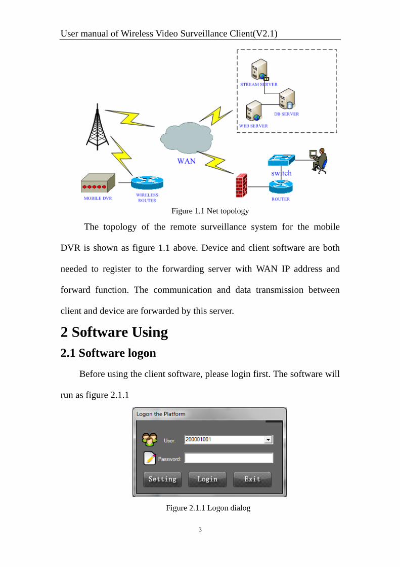
Figure 1.1 Net topology
The topology of the remote surveillance system for the mobile
DVR is shown as figure 1.1 above. Device and client software are both
needed to register to the forwarding server with WAN IP address and
forward function. The communication and data transmission between
client and device are forwarded by this server.
2 Software Using 2.1 Software logon
Before using the client software, please login first. The software will
run as figure 2.1.1
Figure 2.1.1 Logon dialog
User manual of Wireless Video Surveillance Client(V2.1)
4
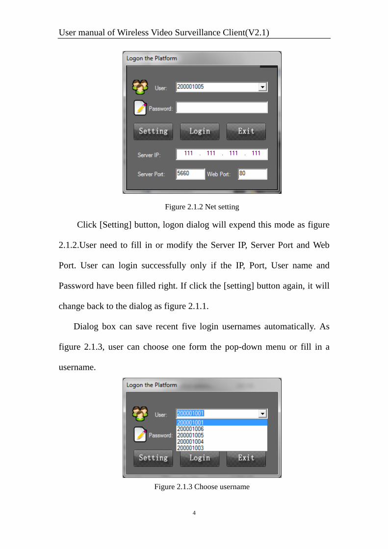
Figure 2.1.2 Net setting
Click [Setting] button, logon dialog will expend this mode as figure
2.1.2.User need to fill in or modify the Server IP, Server Port and Web
Port. User can login successfully only if the IP, Port, User name and
Password have been filled right. If click the [setting] button again, it will
change back to the dialog as figure 2.1.1.
Dialog box can save recent five login usernames automatically. As
figure 2.1.3, user can choose one form the pop-down menu or fill in a
username.
Figure 2.1.3 Choose username
User manual of Wireless Video Surveillance Client(V2.1)
5
After filled in the username, password, and other settings, click the
login button, then it will be as figure 2.1.4 and 2.1.5.
Figure 2.1.4 Login Tip
Figure 2.1.5 Login Tip
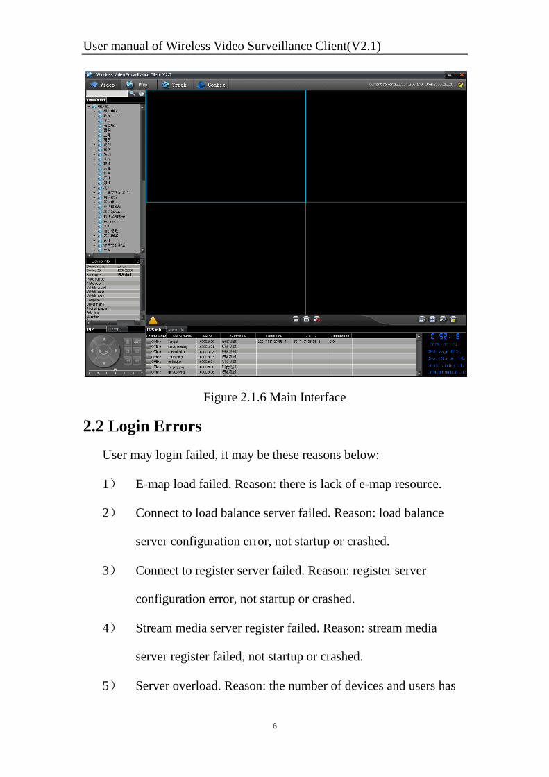
After login, the main interface will be as figure 2.1.6:
User manual of Wireless Video Surveillance Client(V2.1)
6
Figure 2.1.6 Main Interface
2.2 Login Errors User may login failed, it may be these reasons below:
1) E-map load failed. Reason: there is lack of e-map resource.
2) Connect to load balance server failed. Reason: load balance
server configuration error, not startup or crashed.
3) Connect to register server failed. Reason: register server
configuration error, not startup or crashed.
4) Stream media server register failed. Reason: stream media
server register failed, not startup or crashed.
5) Server overload. Reason: the number of devices and users has
User manual of Wireless Video Surveillance Client(V2.1)
7
been out of the load range of the server, current the server can
bear 800 clients.
6) User not exist. Reason: the username has not been registered in
the server.
7) User already online. Reason: other clients have used this
username to login. One username can login by only one client
at the same time.
8) Password error. Reason: input incorrect password.
Note:
The server IP is recommended to be WAN IP address.
Default server port is 5660. Occurrence number should be the
same as the port of load balancing server.
Web port is the management port, it is usually set 80.
Occurrence number should be the same as the port of web server. If
the web port set incorrect, program can login but the device list and
car information can’t be downloaded successfully.
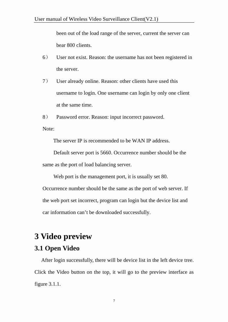
3 Video preview 3.1 Open Video After login successfully, there will be device list in the left device tree.
Click the Video button on the top, it will go to the preview interface as
figure 3.1.1.
User manual of Wireless Video Surveillance Client(V2.1)
8
Figure 3.1.1 Preview interface
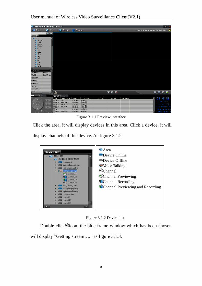
Click the area, it will display devices in this area. Click a device, it will
display channels of this device. As figure 3.1.2
Figure 3.1.2 Device list
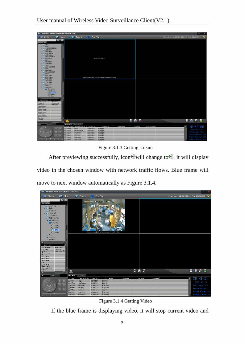
Double click icon, the blue frame window which has been chosen
will display ”Getting stream….” as figure 3.1.3.
Area Device Online Device Offline Voice Talking Channel Channel Previewing Channel Recording Channel Previewing and Recording
User manual of Wireless Video Surveillance Client(V2.1)
9
Figure 3.1.3 Getting stream
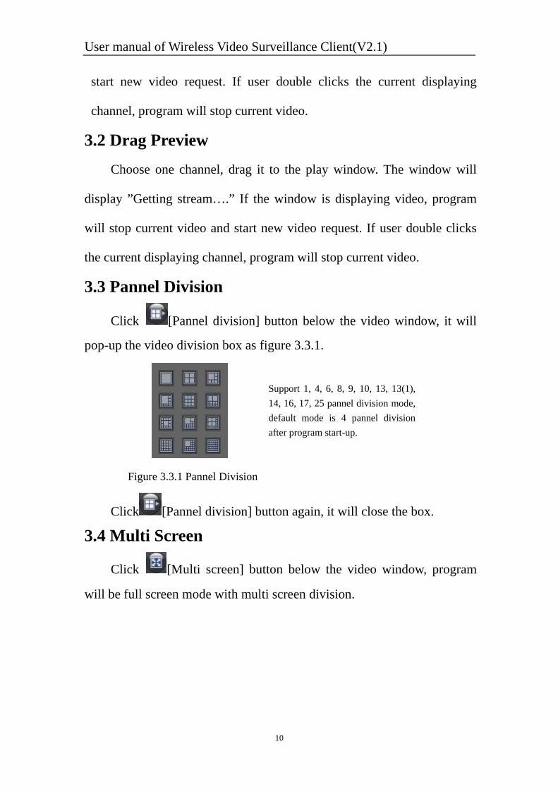
After previewing successfully, icon will change to , it will display
video in the chosen window with network traffic flows. Blue frame will
move to next window automatically as Figure 3.1.4.
Figure 3.1.4 Getting Video
If the blue frame is displaying video, it will stop current video and
User manual of Wireless Video Surveillance Client(V2.1)
10
start new video request. If user double clicks the current displaying
channel, program will stop current video.
3.2 Drag Preview Choose one channel, drag it to the play window. The window will
display ”Getting stream….” If the window is displaying video, program
will stop current video and start new video request. If user double clicks
the current displaying channel, program will stop current video.
3.3 Pannel Division
Click [Pannel division] button below the video window, it will
pop-up the video division box as figure 3.3.1.
Click [Pannel division] button again, it will close the box.
3.4 Multi Screen
Click [Multi screen] button below the video window, program
will be full screen mode with multi screen division.
Support 1, 4, 6, 8, 9, 10, 13, 13(1), 14, 16, 17, 25 pannel division mode, default mode is 4 pannel division after program start-up.
Figure 3.3.1 Pannel Division

User manual of Wireless Video Surveillance Client(V2.1)
11
Figure 3.4.1 Multi Screen
Right click the mouse, popup menu will be as figure 3.4.2, if it is
multi screen mode, the [Multi screen] option would have been chosen.
Click this option, program will go back to normal mode and this option
will be canceled. As figure 3.4.3, user can click it to enter multi screen
again.
Figure 3.4.2 Full screen mode menu Figure3.4.3 Normal mode menu
3.5 Capture User can capture pictures of current previewing video, and save
them in appointed folder. Default path is ”C:\Picture”.
Operation: choose one channel video, click [Capture] button, or right
User manual of Wireless Video Surveillance Client(V2.1)
12
click the playing video, then click the [Capture] option in the popup menu
as figure 3.4.2.
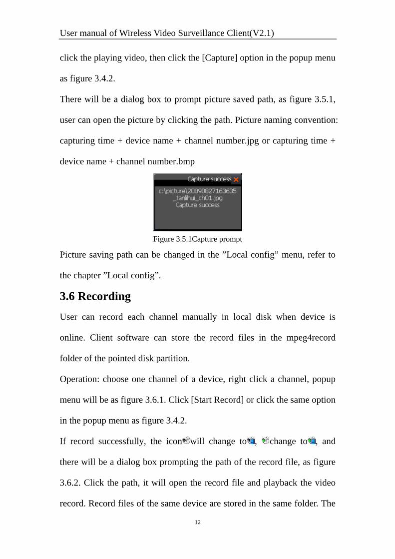
There will be a dialog box to prompt picture saved path, as figure 3.5.1,
user can open the picture by clicking the path. Picture naming convention:
capturing time + device name + channel number.jpg or capturing time +
device name + channel number.bmp
Figure 3.5.1Capture prompt
Picture saving path can be changed in the ”Local config” menu, refer to
the chapter ”Local config”.
3.6 Recording User can record each channel manually in local disk when device is
online. Client software can store the record files in the mpeg4record
folder of the pointed disk partition.
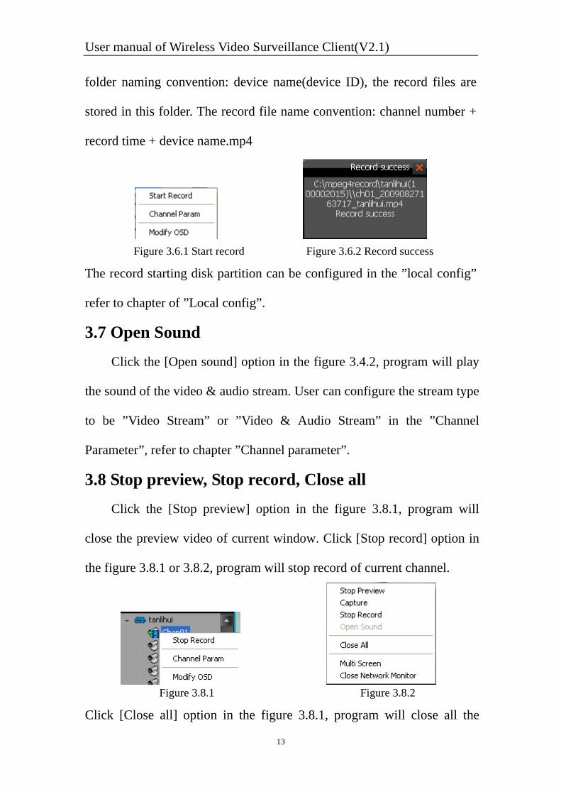
Operation: choose one channel of a device, right click a channel, popup
menu will be as figure 3.6.1. Click [Start Record] or click the same option
in the popup menu as figure 3.4.2.
If record successfully, the icon will change to , change to , and
there will be a dialog box prompting the path of the record file, as figure
3.6.2. Click the path, it will open the record file and playback the video
record. Record files of the same device are stored in the same folder. The
User manual of Wireless Video Surveillance Client(V2.1)
13
folder naming convention: device name(device ID), the record files are
stored in this folder. The record file name convention: channel number +
record time + device name.mp4
Figure 3.6.1 Start record Figure 3.6.2 Record success
The record starting disk partition can be configured in the ”local config”
refer to chapter of ”Local config”.
3.7 Open Sound Click the [Open sound] option in the figure 3.4.2, program will play
the sound of the video & audio stream. User can configure the stream type
to be ”Video Stream” or ”Video & Audio Stream” in the ”Channel
Parameter”, refer to chapter ”Channel parameter”.
3.8 Stop preview, Stop record, Close all Click the [Stop preview] option in the figure 3.8.1, program will
close the preview video of current window. Click [Stop record] option in
the figure 3.8.1 or 3.8.2, program will stop record of current channel.
Figure 3.8.1 Figure 3.8.2
Click [Close all] option in the figure 3.8.1, program will close all the
User manual of Wireless Video Surveillance Client(V2.1)
14
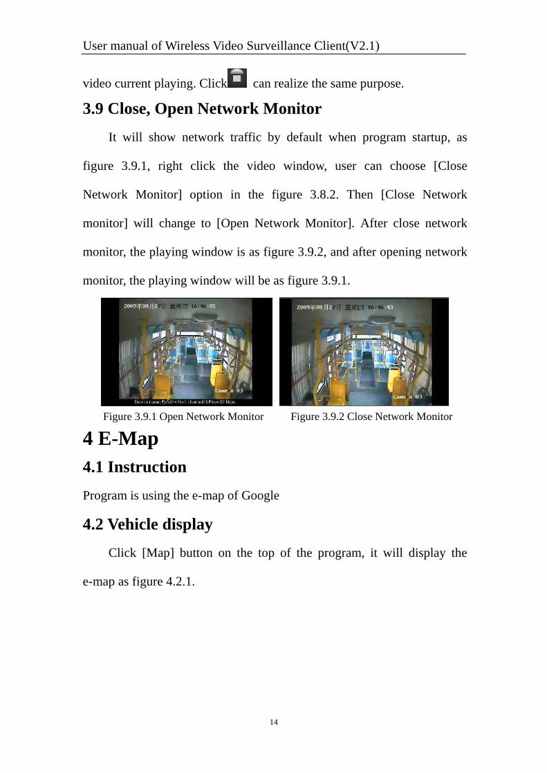
video current playing. Click can realize the same purpose.
3.9 Close, Open Network Monitor It will show network traffic by default when program startup, as
figure 3.9.1, right click the video window, user can choose [Close
Network Monitor] option in the figure 3.8.2. Then [Close Network
monitor] will change to [Open Network Monitor]. After close network
monitor, the playing window is as figure 3.9.2, and after opening network
monitor, the playing window will be as figure 3.9.1.
Figure 3.9.1 Open Network Monitor Figure 3.9.2 Close Network Monitor
4 E-Map 4.1 Instruction Program is using the e-map of Google
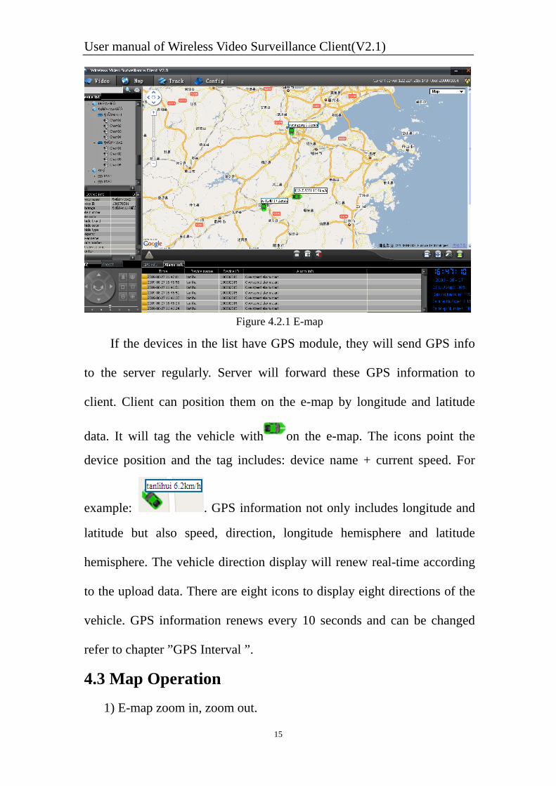
4.2 Vehicle display Click [Map] button on the top of the program, it will display the
e-map as figure 4.2.1.
User manual of Wireless Video Surveillance Client(V2.1)
15
Figure 4.2.1 E-map
If the devices in the list have GPS module, they will send GPS info
to the server regularly. Server will forward these GPS information to
client. Client can position them on the e-map by longitude and latitude
data. It will tag the vehicle with on the e-map. The icons point the
device position and the tag includes: device name + current speed. For
example: . GPS information not only includes longitude and
latitude but also speed, direction, longitude hemisphere and latitude
hemisphere. The vehicle direction display will renew real-time according
to the upload data. There are eight icons to display eight directions of the
vehicle. GPS information renews every 10 seconds and can be changed
refer to chapter ”GPS Interval ”.
4.3 Map Operation 1) E-map zoom in, zoom out.
User manual of Wireless Video Surveillance Client(V2.1)
16
Double click the e-map can zoom in.
Scroll the mouse wheel, user can zoom in and zoom out. Forward
scrolling to zoom in and back scrolling to zoom out.
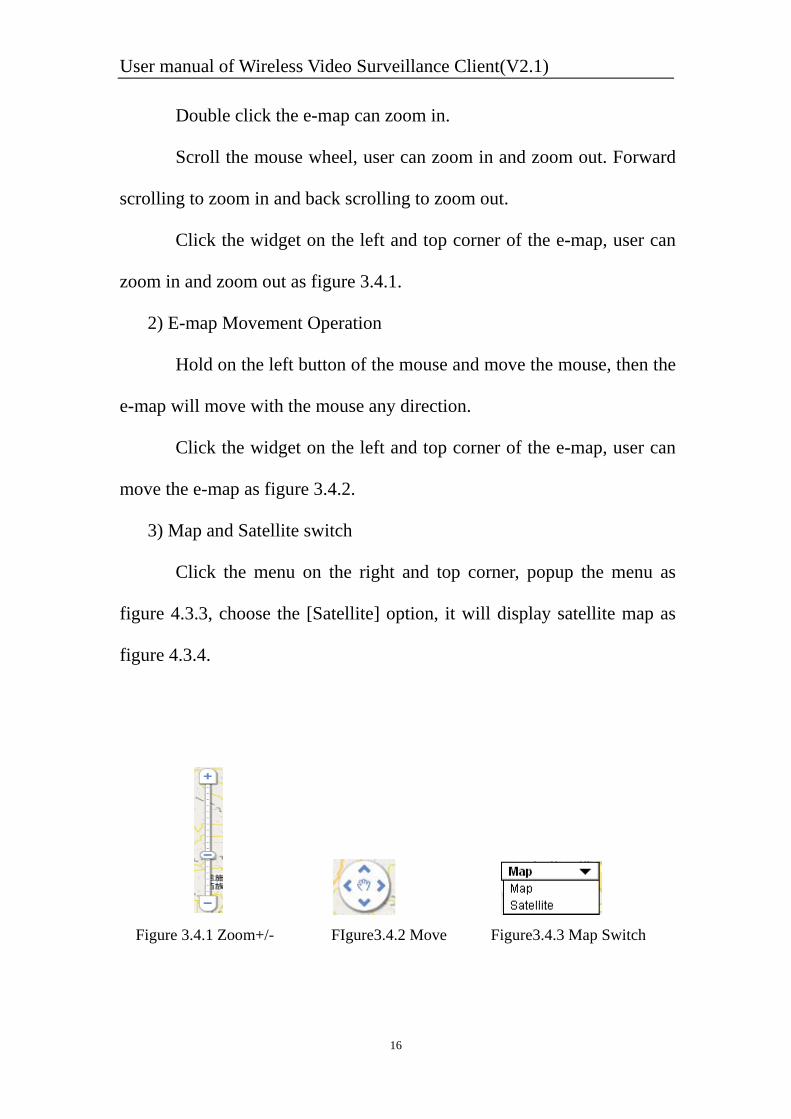
Click the widget on the left and top corner of the e-map, user can
zoom in and zoom out as figure 3.4.1.
2) E-map Movement Operation
Hold on the left button of the mouse and move the mouse, then the
e-map will move with the mouse any direction.
Click the widget on the left and top corner of the e-map, user can
move the e-map as figure 3.4.2.
3) Map and Satellite switch
Click the menu on the right and top corner, popup the menu as
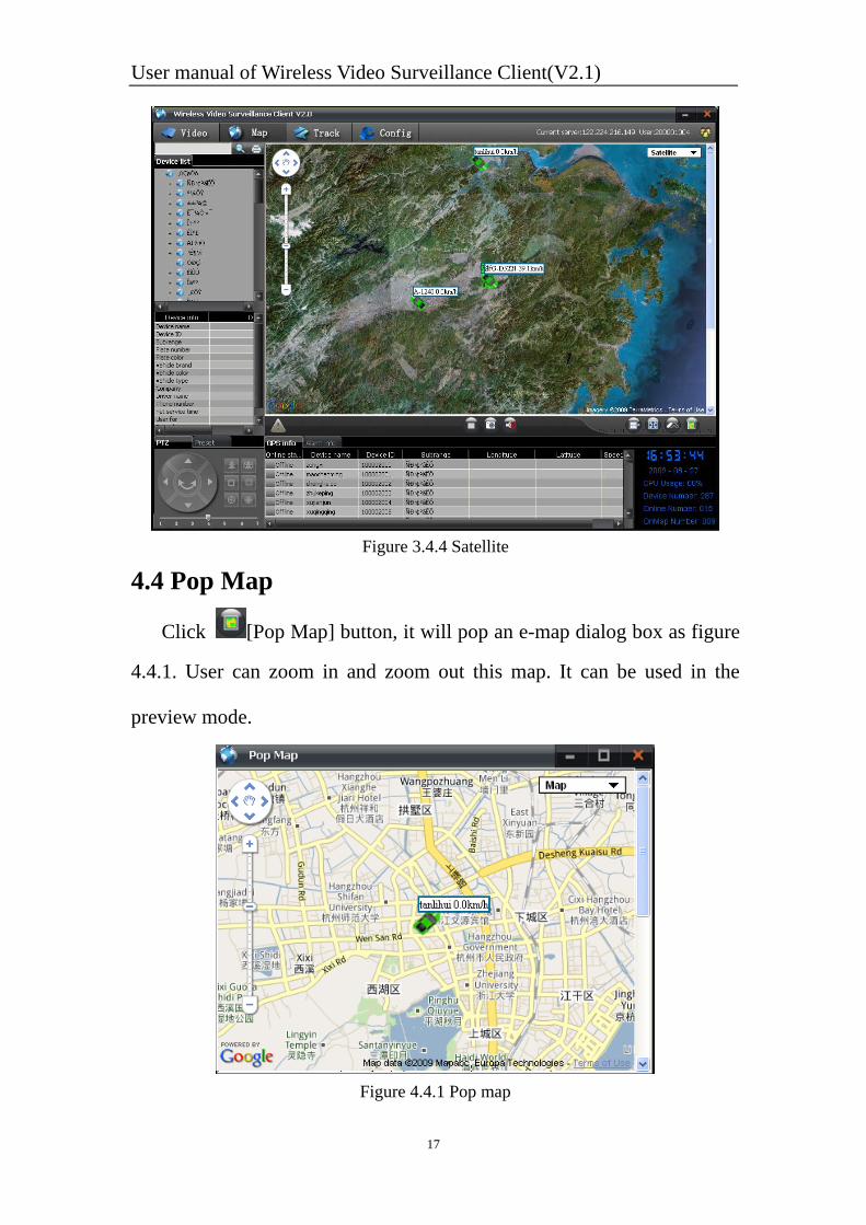
figure 4.3.3, choose the [Satellite] option, it will display satellite map as
figure 4.3.4.
Figure 3.4.1 Zoom+/- FIgure3.4.2 Move Figure3.4.3 Map Switch
User manual of Wireless Video Surveillance Client(V2.1)
17
Figure 3.4.4 Satellite
4.4 Pop Map
Click [Pop Map] button, it will pop an e-map dialog box as figure
4.4.1. User can zoom in and zoom out this map. It can be used in the
preview mode.
Figure 4.4.1 Pop map
User manual of Wireless Video Surveillance Client(V2.1)
18
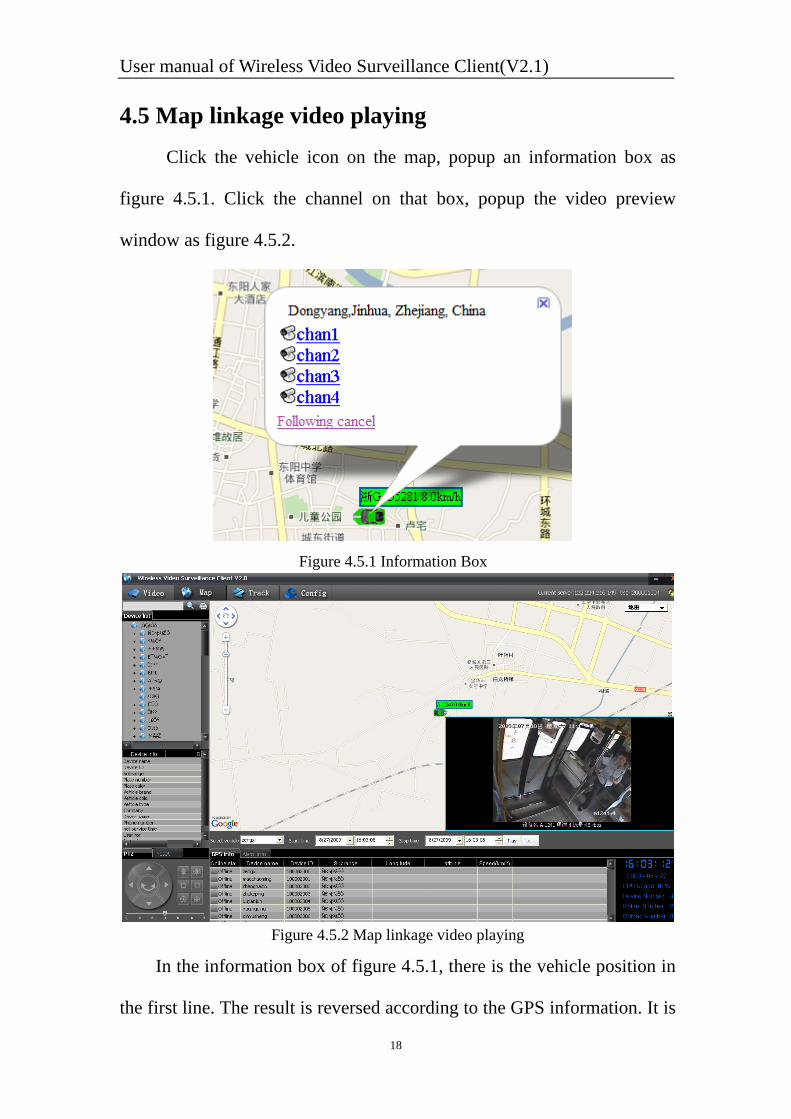
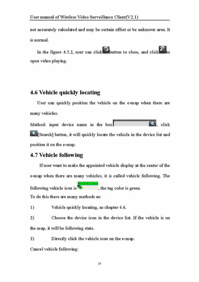
4.5 Map linkage video playing Click the vehicle icon on the map, popup an information box as
figure 4.5.1. Click the channel on that box, popup the video preview
window as figure 4.5.2.
Figure 4.5.1 Information Box
Figure 4.5.2 Map linkage video playing
In the information box of figure 4.5.1, there is the vehicle position in
the first line. The result is reversed according to the GPS information. It is
User manual of Wireless Video Surveillance Client(V2.1)
21
Figure 5.1.2 No track point note
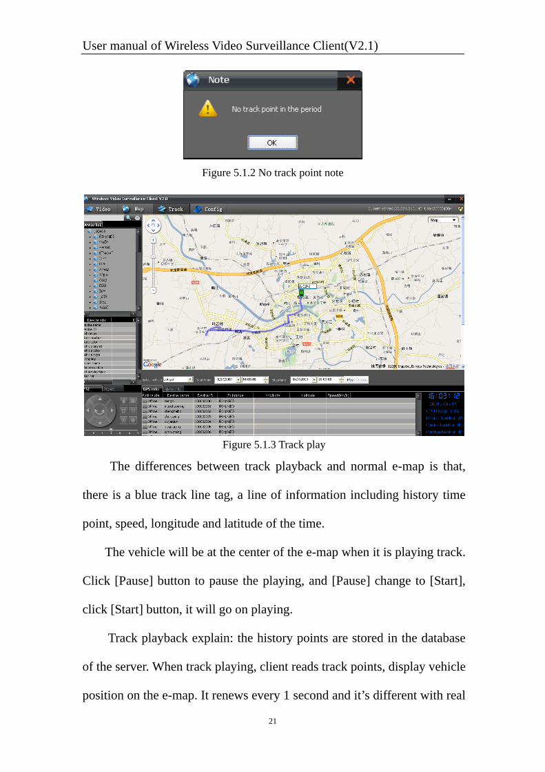
Figure 5.1.3 Track play
The differences between track playback and normal e-map is that,
there is a blue track line tag, a line of information including history time
point, speed, longitude and latitude of the time.
The vehicle will be at the center of the e-map when it is playing track.
Click [Pause] button to pause the playing, and [Pause] change to [Start],
click [Start] button, it will go on playing.
Track playback explain: the history points are stored in the database
of the server. When track playing, client reads track points, display vehicle
position on the e-map. It renews every 1 second and it’s different with real
User manual of Wireless Video Surveillance Client(V2.1)
22
speed because the vehicle default GPS interval is 10 seconds. Server
would save GPS data for a week.
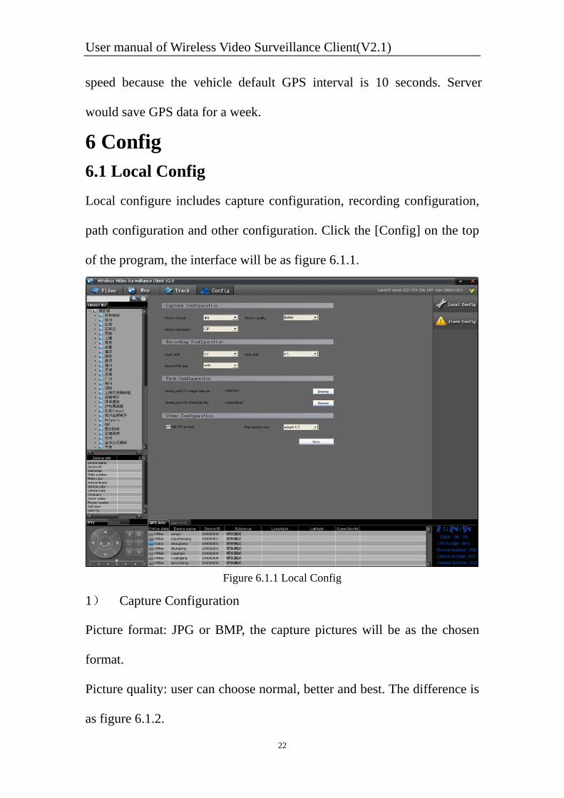
6 Config 6.1 Local Config Local configure includes capture configuration, recording configuration,
path configuration and other configuration. Click the [Config] on the top
of the program, the interface will be as figure 6.1.1.
Figure 6.1.1 Local Config
1) Capture Configuration
Picture format: JPG or BMP, the capture pictures will be as the chosen
format.
Picture quality: user can choose normal, better and best. The difference is
as figure 6.1.2.
User manual of Wireless Video Surveillance Client(V2.1)
23
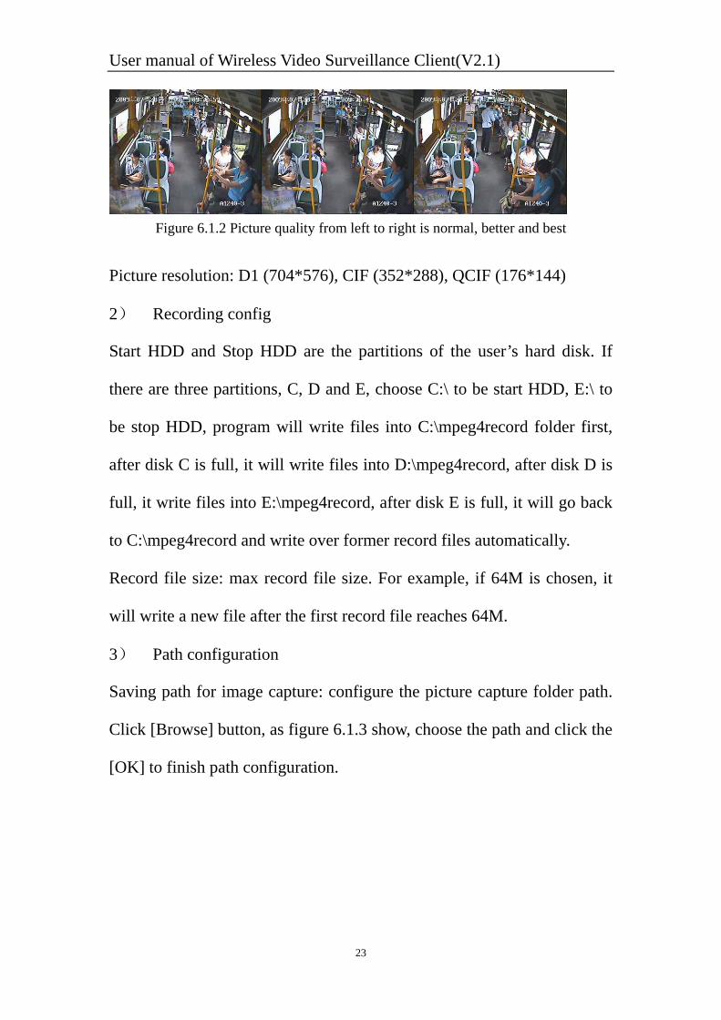
Figure 6.1.2 Picture quality from left to right is normal, better and best
Picture resolution: D1 (704*576), CIF (352*288), QCIF (176*144)
2) Recording config
Start HDD and Stop HDD are the partitions of the user’s hard disk. If
there are three partitions, C, D and E, choose C:\ to be start HDD, E:\ to
be stop HDD, program will write files into C:\mpeg4record folder first,
after disk C is full, it will write files into D:\mpeg4record, after disk D is
full, it write files into E:\mpeg4record, after disk E is full, it will go back
to C:\mpeg4record and write over former record files automatically.
Record file size: max record file size. For example, if 64M is chosen, it
will write a new file after the first record file reaches 64M.
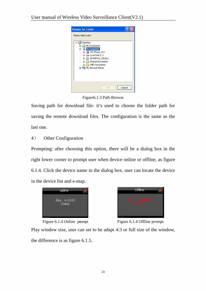
3) Path configuration
Saving path for image capture: configure the picture capture folder path.
Click [Browse] button, as figure 6.1.3 show, choose the path and click the
[OK] to finish path configuration.
User manual of Wireless Video Surveillance Client(V2.1)
24
Figure6.1.3 Path Browse
Saving path for download file: it’s used to choose the folder path for
saving the remote download files. The configuration is the same as the
last one.
4) Other Configuration
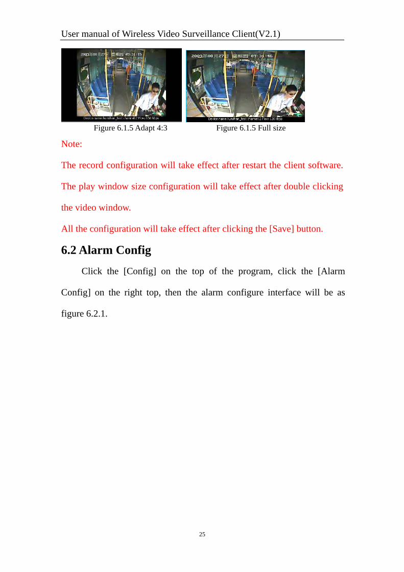
Prompting: after choosing this option, there will be a dialog box in the
right lower corner to prompt user when device online or offline, as figure
6.1.4. Click the device name in the dialog box, user can locate the device
in the device list and e-map.
Figure 6.1.4 Online prompt Figure 6.1.4 Offline prompt
Play window size, user can set to be adapt 4:3 or full size of the window,
the difference is as figure 6.1.5.
User manual of Wireless Video Surveillance Client(V2.1)
25
Figure 6.1.5 Adapt 4:3 Figure 6.1.5 Full size
Note:
The record configuration will take effect after restart the client software.
The play window size configuration will take effect after double clicking
the video window.
All the configuration will take effect after clicking the [Save] button.
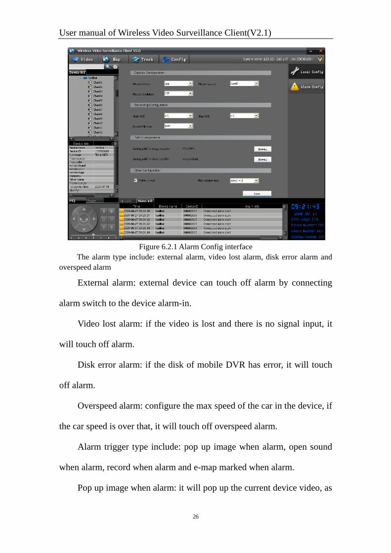
6.2 Alarm Config Click the [Config] on the top of the program, click the [Alarm
Config] on the right top, then the alarm configure interface will be as
figure 6.2.1.
User manual of Wireless Video Surveillance Client(V2.1)
26
Figure 6.2.1 Alarm Config interface
The alarm type include: external alarm, video lost alarm, disk error alarm and overspeed alarm
External alarm: external device can touch off alarm by connecting
alarm switch to the device alarm-in.
Video lost alarm: if the video is lost and there is no signal input, it
will touch off alarm.
Disk error alarm: if the disk of mobile DVR has error, it will touch
off alarm.
Overspeed alarm: configure the max speed of the car in the device, if
the car speed is over that, it will touch off overspeed alarm.
Alarm trigger type include: pop up image when alarm, open sound
when alarm, record when alarm and e-map marked when alarm.
Pop up image when alarm: it will pop up the current device video, as
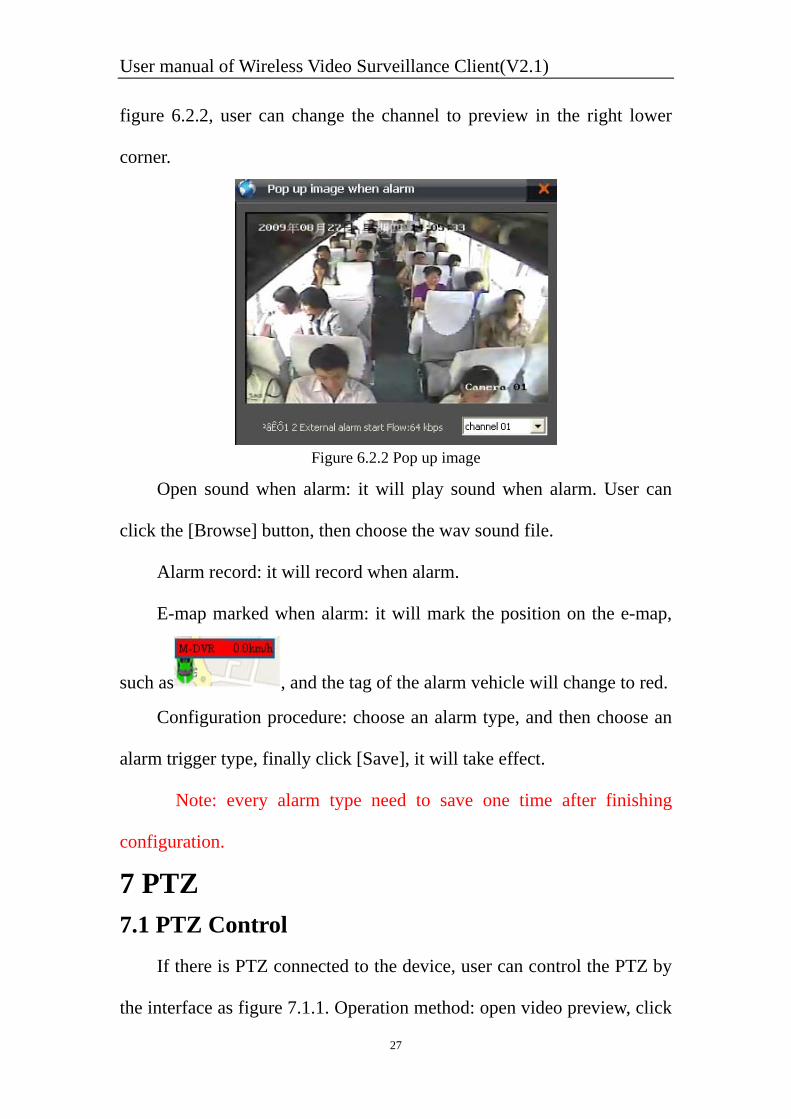
User manual of Wireless Video Surveillance Client(V2.1)
27
figure 6.2.2, user can change the channel to preview in the right lower
corner.
Figure 6.2.2 Pop up image
Open sound when alarm: it will play sound when alarm. User can
click the [Browse] button, then choose the wav sound file.
Alarm record: it will record when alarm.
E-map marked when alarm: it will mark the position on the e-map,
such as , and the tag of the alarm vehicle will change to red.
Configuration procedure: choose an alarm type, and then choose an
alarm trigger type, finally click [Save], it will take effect.
Note: every alarm type need to save one time after finishing
configuration.
7 PTZ 7.1 PTZ Control If there is PTZ connected to the device, user can control the PTZ by
the interface as figure 7.1.1. Operation method: open video preview, click
User manual of Wireless Video Surveillance Client(V2.1)
28
the playing window, and then control the PTZ.
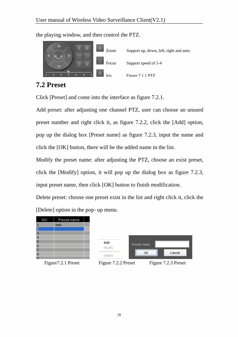
7.2 Preset Click [Preset] and come into the interface as figure 7.2.1.
Add preset: after adjusting one channel PTZ, user can choose an unused
preset number and right click it, as figure 7.2.2, click the [Add] option,
pop up the dialog box [Preset name] as figure 7.2.3, input the name and
click the [OK] button, there will be the added name in the list.
Modify the preset name: after adjusting the PTZ, choose an exist preset,
click the [Modify] option, it will pop up the dialog box as figure 7.2.3,
input preset name, then click [OK] button to finish modification.
Delete preset: choose one preset exist in the list and right click it, click the
[Delete] option in the pop- up menu.
Figure7.2.1 Preset Figure 7.2.2 Preset Figure 7.2.3 Preset
Zoom Support up, down, left, right and auto.
Focus Support speed of 1-4
Iris Figure 7.1.1 PTZ
User manual of Wireless Video Surveillance Client(V2.1)
29
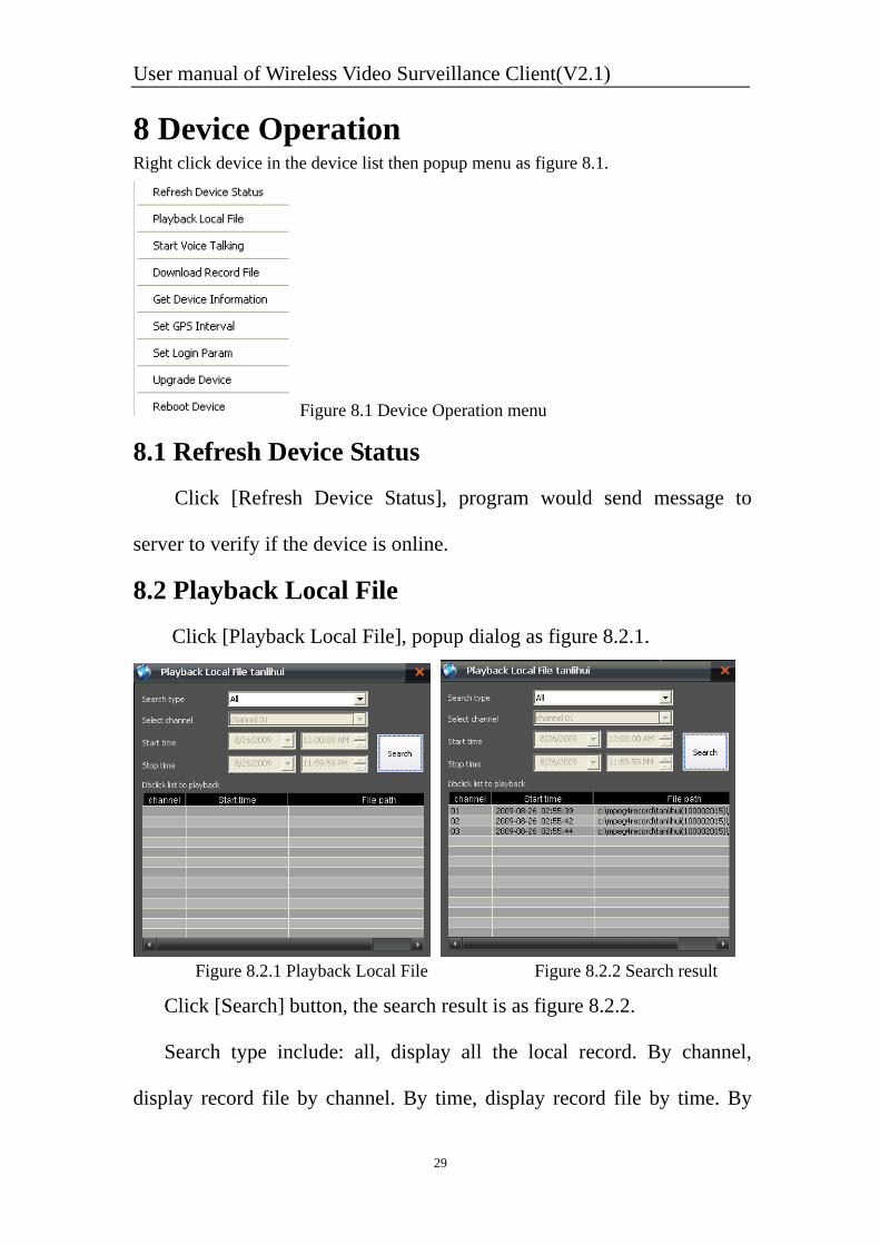
8 Device Operation Right click device in the device list then popup menu as figure 8.1.
Figure 8.1 Device Operation menu
8.1 Refresh Device Status Click [Refresh Device Status], program would send message to
server to verify if the device is online.
8.2 Playback Local File Click [Playback Local File], popup dialog as figure 8.2.1.
Figure 8.2.1 Playback Local File Figure 8.2.2 Search result
Click [Search] button, the search result is as figure 8.2.2.
Search type include: all, display all the local record. By channel,
display record file by channel. By time, display record file by time. By
User manual of Wireless Video Surveillance Client(V2.1)
30
channel & time, display record file by channel and time.
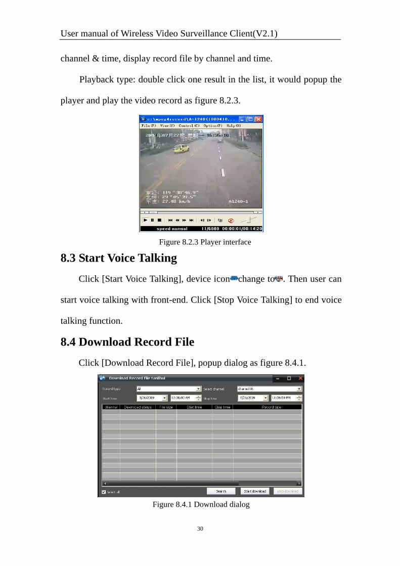
Playback type: double click one result in the list, it would popup the
player and play the video record as figure 8.2.3.
Figure 8.2.3 Player interface
8.3 Start Voice Talking Click [Start Voice Talking], device icon change to . Then user can
start voice talking with front-end. Click [Stop Voice Talking] to end voice
talking function.
8.4 Download Record File Click [Download Record File], popup dialog as figure 8.4.1.
Figure 8.4.1 Download dialog
User manual of Wireless Video Surveillance Client(V2.1)
31
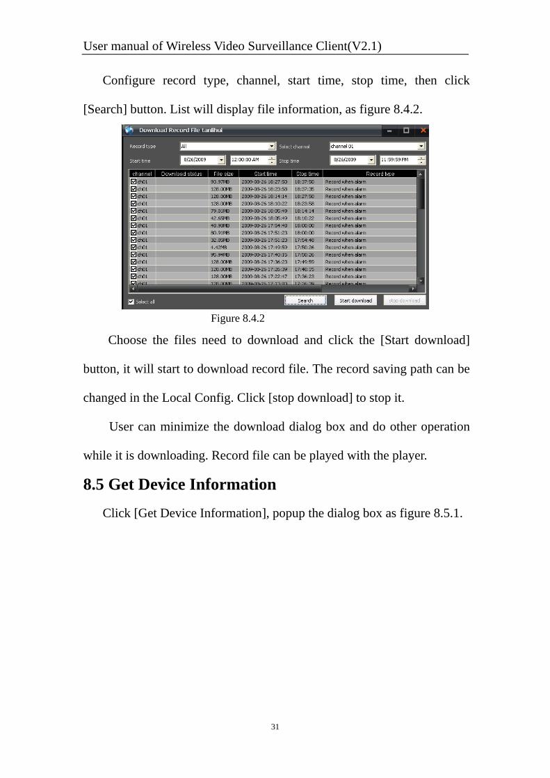
Configure record type, channel, start time, stop time, then click
[Search] button. List will display file information, as figure 8.4.2.
Figure 8.4.2
Choose the files need to download and click the [Start download]
button, it will start to download record file. The record saving path can be
changed in the Local Config. Click [stop download] to stop it.
User can minimize the download dialog box and do other operation
while it is downloading. Record file can be played with the player.
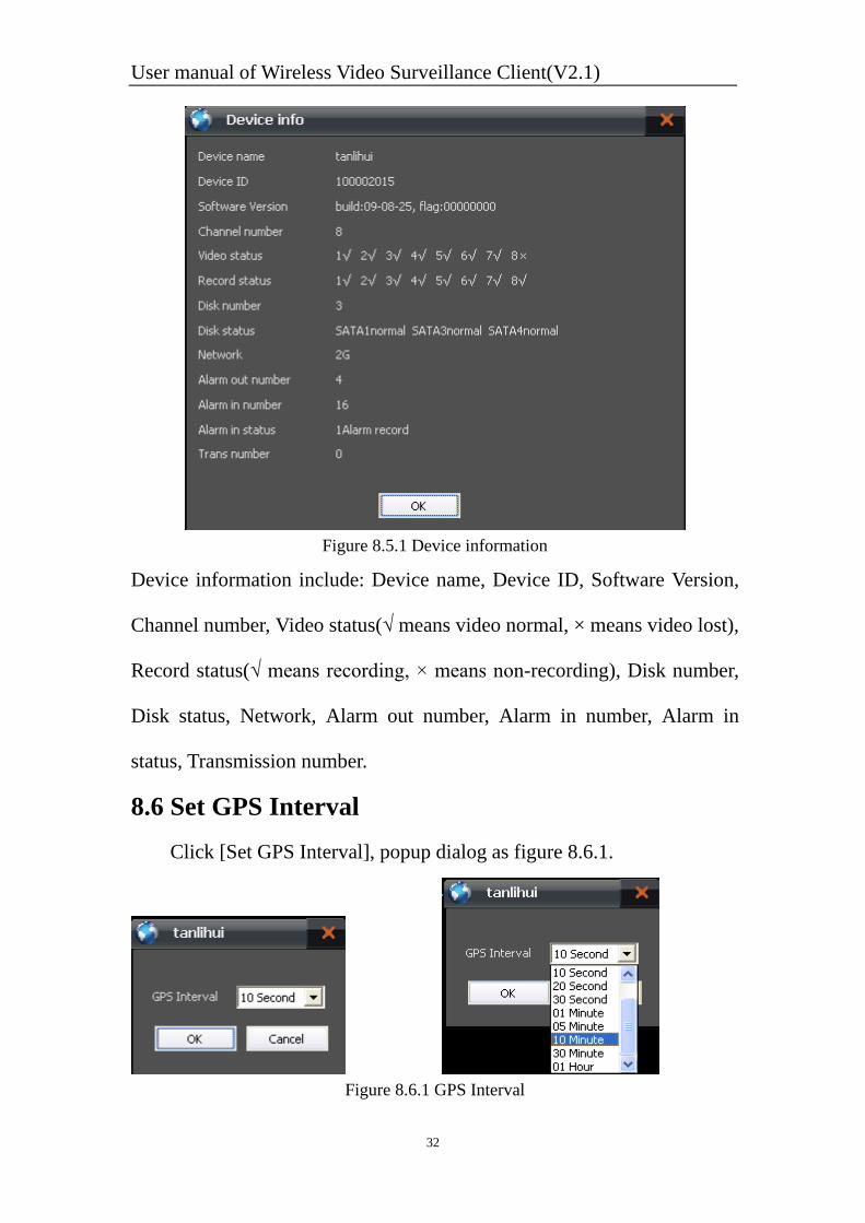
8.5 Get Device Information Click [Get Device Information], popup the dialog box as figure 8.5.1.
User manual of Wireless Video Surveillance Client(V2.1)
32
Figure 8.5.1 Device information
Device information include: Device name, Device ID, Software Version,
Channel number, Video status(√ means video normal, × means video lost),
Record status(√ means recording, × means non-recording), Disk number,
Disk status, Network, Alarm out number, Alarm in number, Alarm in
status, Transmission number.
8.6 Set GPS Interval Click [Set GPS Interval], popup dialog as figure 8.6.1.
Figure 8.6.1 GPS Interval
User manual of Wireless Video Surveillance Client(V2.1)
33
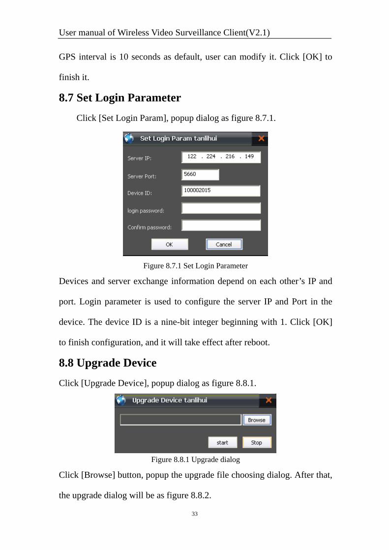
GPS interval is 10 seconds as default, user can modify it. Click [OK] to
finish it.
8.7 Set Login Parameter Click [Set Login Param], popup dialog as figure 8.7.1.
Figure 8.7.1 Set Login Parameter
Devices and server exchange information depend on each other’s IP and
port. Login parameter is used to configure the server IP and Port in the
device. The device ID is a nine-bit integer beginning with 1. Click [OK]
to finish configuration, and it will take effect after reboot.
8.8 Upgrade Device Click [Upgrade Device], popup dialog as figure 8.8.1.
Figure 8.8.1 Upgrade dialog
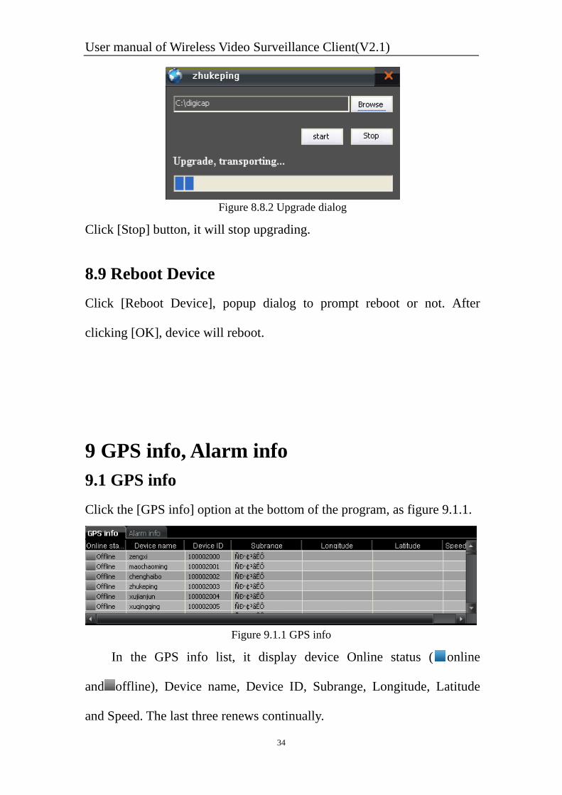
Click [Browse] button, popup the upgrade file choosing dialog. After that,
the upgrade dialog will be as figure 8.8.2.
User manual of Wireless Video Surveillance Client(V2.1)
34
Figure 8.8.2 Upgrade dialog
Click [Stop] button, it will stop upgrading.
8.9 Reboot Device Click [Reboot Device], popup dialog to prompt reboot or not. After
clicking [OK], device will reboot.
9 GPS info, Alarm info 9.1 GPS info Click the [GPS info] option at the bottom of the program, as figure 9.1.1.
Figure 9.1.1 GPS info
In the GPS info list, it display device Online status ( online
and offline), Device name, Device ID, Subrange, Longitude, Latitude
and Speed. The last three renews continually.
User manual of Wireless Video Surveillance Client(V2.1)
35
Click one line of the info, it will locate the device in the device list
and position the device on the e-map.
Right click the info list, it will popup the dialog as figure 9.1.2. User
can order the info list by online status, by device name, by device ID and
by subrange.
Figure 9.1.2 Order menu
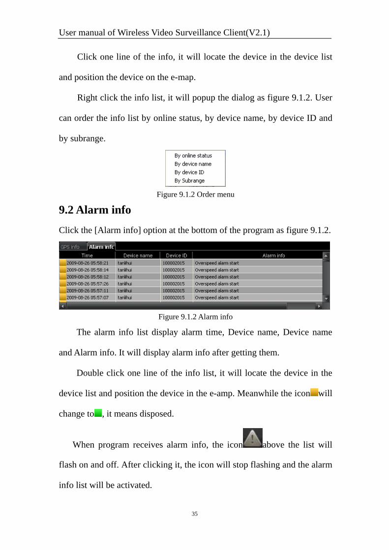
9.2 Alarm info Click the [Alarm info] option at the bottom of the program as figure 9.1.2.
Figure 9.1.2 Alarm info
The alarm info list display alarm time, Device name, Device name
and Alarm info. It will display alarm info after getting them.
Double click one line of the info list, it will locate the device in the
device list and position the device in the e-amp. Meanwhile the icon will
change to , it means disposed.
When program receives alarm info, the icon above the list will
flash on and off. After clicking it, the icon will stop flashing and the alarm
info list will be activated.
User manual of Wireless Video Surveillance Client(V2.1)
36
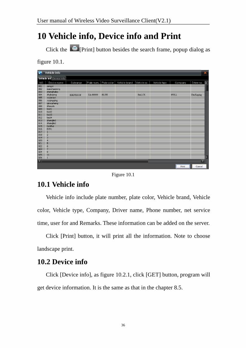
10 Vehicle info, Device info and Print Click the [Print] button besides the search frame, popup dialog as
figure 10.1.
Figure 10.1
10.1 Vehicle info Vehicle info include plate number, plate color, Vehicle brand, Vehicle
color, Vehicle type, Company, Driver name, Phone number, net service
time, user for and Remarks. These information can be added on the server.
Click [Print] button, it will print all the information. Note to choose
landscape print.
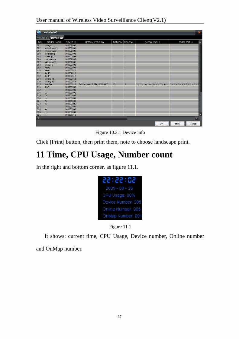
10.2 Device info Click [Device info], as figure 10.2.1, click [GET] button, program will
get device information. It is the same as that in the chapter 8.5.
User manual of Wireless Video Surveillance Client(V2.1)
37
Figure 10.2.1 Device info
Click [Print] button, then print them, note to choose landscape print.
11 Time, CPU Usage, Number count In the right and bottom corner, as figure 11.1.
Figure 11.1
It shows: current time, CPU Usage, Device number, Online number
and OnMap number.