wireless technologies for network service providers whitepaper
TRANSCRIPT

FPGA Implementation of an Asynchronous Processor with Both Online and Offline
Testing Capabilities
Nikolaos Minas Matthew Marshall
Gordon RussellAlex Yakovlev

Outline
Introduction.Error Detection/Correction overview.Information Redundancy Scheme.Dong’s Code.CED Pipeline.Asynchronous Reconfigurable Tester.Results.Conclusions.
Introduction
Technological advances reduce reliability of components due to:
Process variationReduction in power supply voltagesHigh operating frequencies
These factors increase the occurrence of transient and intermittent faults.

Intermittent and Transient Fault characteristics
Intermittent
Poor fabrication.Process Variation.
Occur repeatedly at a give location.Errors occur in bursts once activated.
Transient
Alpha or neuron particles.Power supply transients.Interconnect noise.EMI
Random and short duration.
Error Detection/Correction Overview
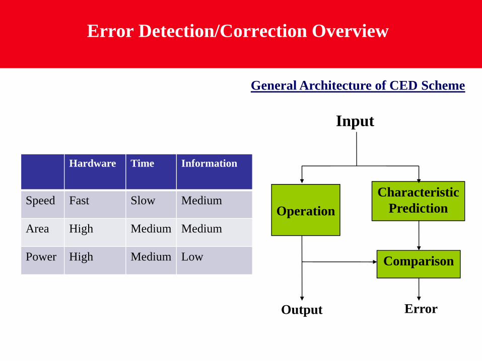
Hardware Time Information
Speed Fast Slow Medium
Area High Medium Medium
Power High Medium Low
General Architecture of CED Scheme
Comparison
CharacteristicPrediction
Input
Output Error
Operation
Information Redundancy Schemes
Check bits are attached to the data bits to form a code word.For all input combinations only a subset represents valid information.
In Berger code the number of check bits is a function of the data bits.In Dong’s code the number of check bits are a function of error coverage.
Dong’s Code Formation
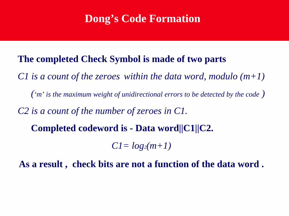
The completed Check Symbol is made of two parts
C1 is a count of the zeroes within the data word, modulo (m+1)
(‘m’ is the maximum weight of unidirectional errors to be detected by the code )
C2 is a count of the number of zeroes in C1.
Completed codeword is - Data word||C1||C2.
C1= log2(m+1)
As a result , check bits are not a function of the data word .
Check Symbol Prediction
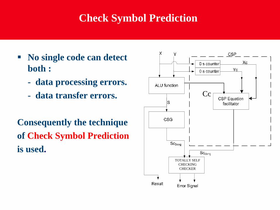
No single code can detect both :- data processing errors.- data transfer errors.
Consequently the techniqueof Check Symbol Predictionis used.
Cc
TOTALLY SELF CHECKING CHECKER

Pipeline Processor
To demonstrate the applicability of Dong’s Code, a 32-bitasynchronous RISC based processor was implemented.
The processor has a repertoire of 32 instructions relatedto:
ALU Operation 18 instructions
Program Flow 9 instructions
Memory Access 2 instructions
System set Op. 6 instructions

CED Pipeline Architecture
Fetch Instruction Decode Execute in ALU
Writeback to register
Register file
Registers RequiredValues
Value & Check Symbol
Check symbols
Check Symbol Generator
(CSG)
Check Symbol Prediction (CSP)
Check
Check Symbol
Check Symbol
Error No error
Values
ValueALU output
Check Symbol
Error signal
Asynchronous Reconfigurable Tester
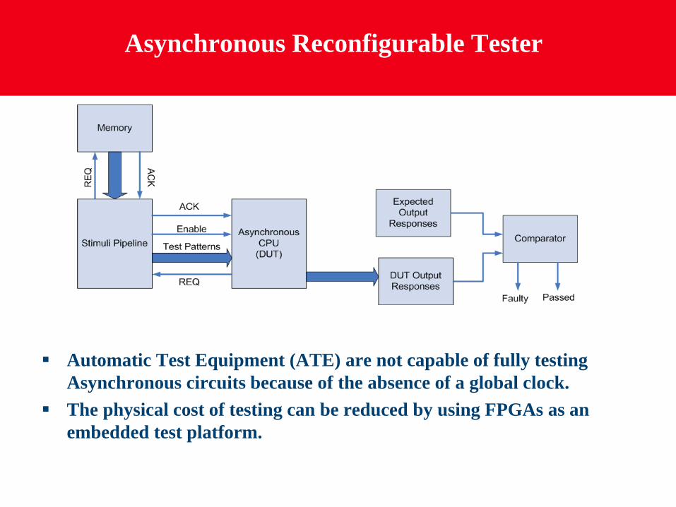
Automatic Test Equipment (ATE) are not capable of fully testing Asynchronous circuits because of the absence of a global clock.The physical cost of testing can be reduced by using FPGAs as an embedded test platform.
Stimuli Pipeline Architecture
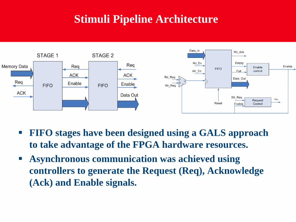
FIFO stages have been designed using a GALS approach to take advantage of the FPGA hardware resources.Asynchronous communication was achieved using controllers to generate the Request (Req), Acknowledge (Ack) and Enable signals.

Error Mapping
Fault-Free Output
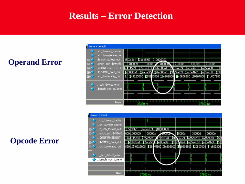
Results – Error Detection
Operand Error
Opcode Error
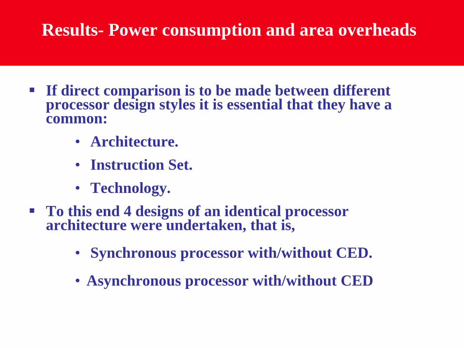
Results- Power consumption and area overheads
If direct comparison is to be made between different processor design styles it is essential that they have a common:
• Architecture.• Instruction Set.• Technology.
To this end 4 designs of an identical processor architecture were undertaken, that is,
• Synchronous processor with/without CED.
• Asynchronous processor with/without CED

Results – Power Dissipation ASIC
0
20
40
60
80
100
120
140
160
Async Async CED Sync Sync CED
Pow
er (m
W)
Architecture

Results – Power Dissipation FPGA
0100200300400500600700800900
Async Async CED Sync Sync CED
Pow
er(m
W)
Architecture

Results – Area Overhead
Sync 0%
Async -4%
Async CED 20%Sync CED 26%
Sync 0%
Async -4%
Async CED 13%Sync CED 17%
ASIC FPGA

FPGA Layout
The asynchronous CED processorand the asynchronous tester wereimplemented in a Virtex2-1000FPGA from Xilinx.
The system utilised 57% of the total FPGA area.
The processor comprises 5375 LUTs and the tester 517 LUTs

Asynchronous Circuit on FPGAs
Problems
Timing closurePlace and RouteDelay Chains
Solutions
Control Signals placed as clocks.Manual P&R.Use of carry chain gates to create predictable delays.

Conclusions
32-bit asynchronous RISC based processor with CED was designed in both ASIC and FPGA.Implementation of an asynchronous reconfigurable tester.Results showed that the asynchronous CED processor offers significant advantages over the synchronous equivalent, in area overheads and power consumption.
ASIC FPGAArea 4% 6%Power 25% 29%

Thank you!!
Any Questions?
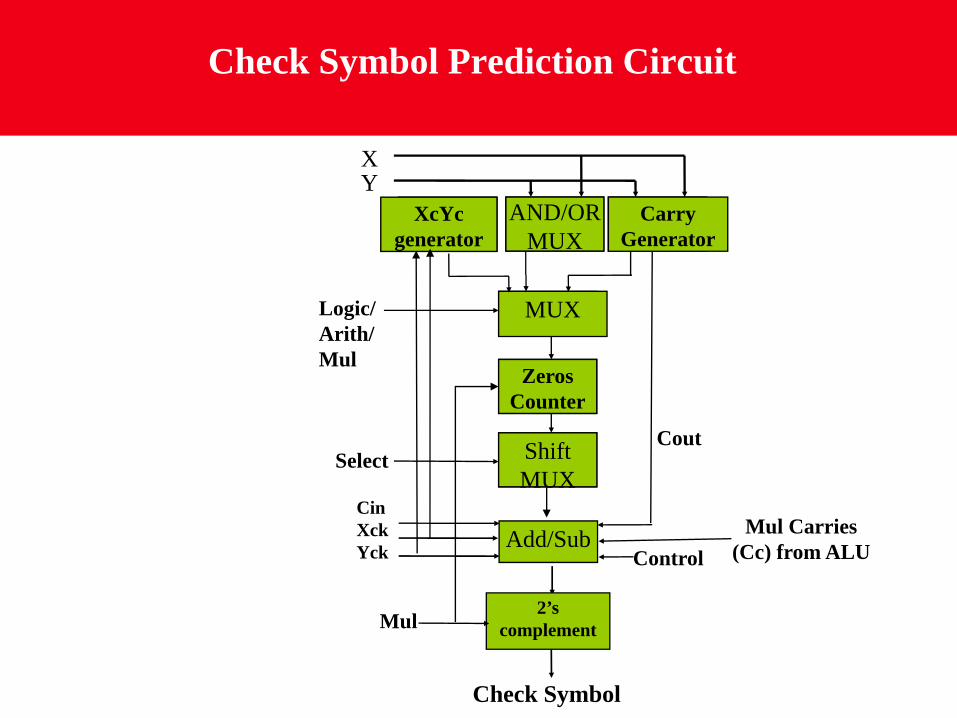
Check Symbol Prediction Circuit
AND/OR MUX
Carry Generator
MUX
Zeros Counter
Shift MUX
Add/Sub
XY
Select
CinXckYck Control
Check Symbol
2’s complementMul
Logic/Arith/Mul
Mul Carries (Cc) from ALU
XcYc generator
Cout
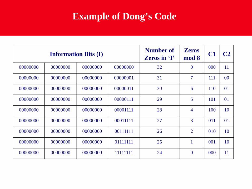
Example of Dong’s Code
Information Bits (I) Number ofZeros in ‘I’
Zerosmod 8 C1 C2
00000000 00000000 00000000 00000000 32 0 000 11
00000000 00000000 00000000 00000001 31 7 111 00
00000000 00000000 00000000 00000011 30 6 110 01
00000000 00000000 00000000 00000111 29 5 101 01
00000000 00000000 00000000 00001111 28 4 100 10
00000000 00000000 00000000 00011111 27 3 011 01
00000000 00000000 00000000 00111111 26 2 010 10
00000000 00000000 00000000 01111111 25 1 001 10
00000000 00000000 00000000 11111111 24 0 000 11

Error Coverage for Dong’s Code
Information Bits Value of ‘m’ Bits in C1 Error Coverage (%)
16 3 2 93.74
32 3 2 93.75
48 3 2 93.75
64 3 2 93.75
16 7 3 99.04
32 7 3 98.54
48 7 3 98.3364 7 3 98.47
‘m’ is the maximum weight of unidirectional errors to be detected by the code
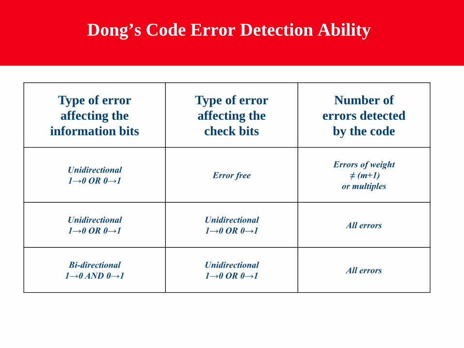
Dong’s Code Error Detection Ability
Type of erroraffecting the
information bits
Type of erroraffecting the
check bits
Number of errors detected
by the code
Unidirectional1→0 OR 0→1 Error free
Errors of weight≠ (m+1)
or multiples
Unidirectional1→0 OR 0→1
Unidirectional1→0 OR 0→1 All errors
Bi-directional1→0 AND 0→1
Unidirectional1→0 OR 0→1 All errors
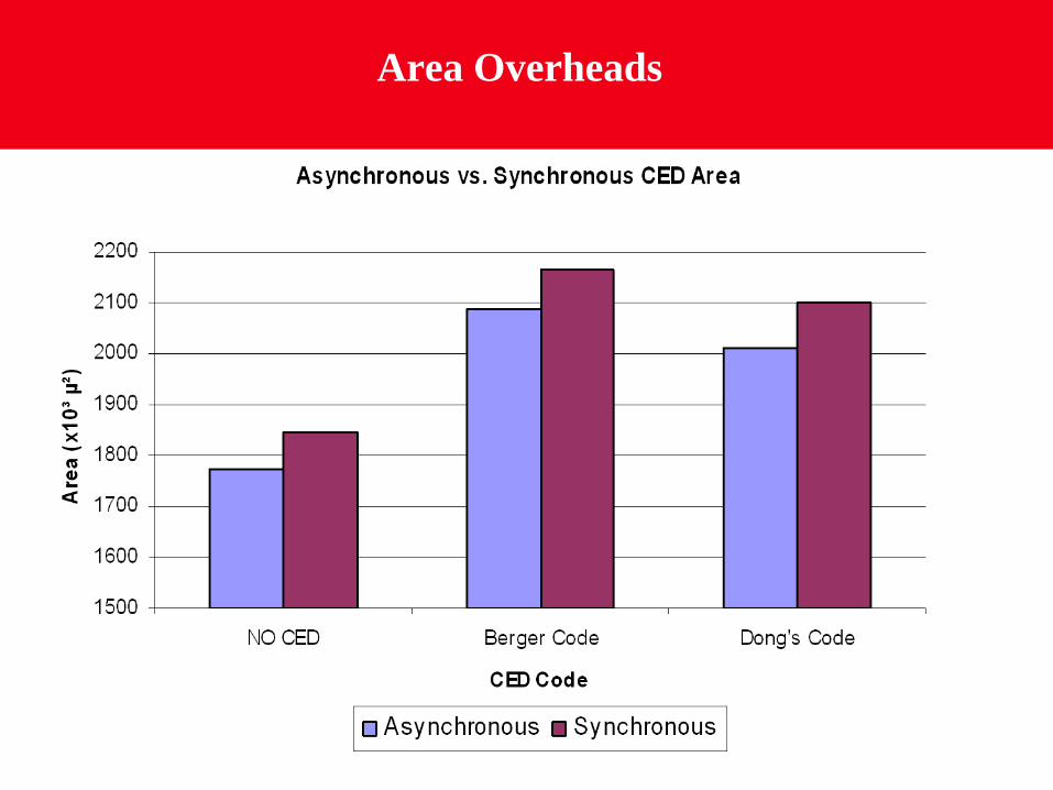
Area Overheads