wireless sensor networks - diees - home page · zigbee • introduction ... • profiles/cluster...
TRANSCRIPT
Wireless Sensor NetworksWireless Sensor Networks
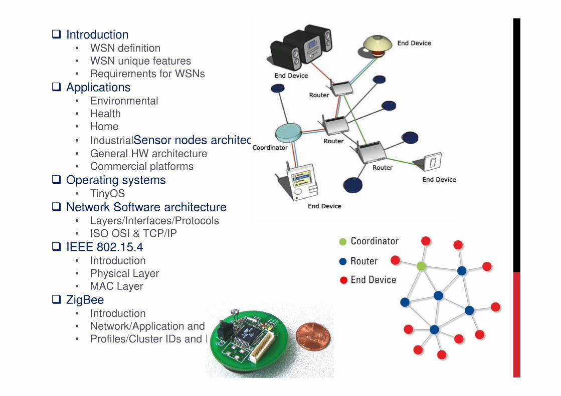
� Introduction• WSN definition
• WSN unique features
• Requirements for WSNs
� Applications• Environmental
• Health
• Home
• IndustrialSensor nodes architecture• General HW architecture
• Commercial platforms
� Operating systems• TinyOS• TinyOS
� Network Software architecture• Layers/Interfaces/Protocols
• ISO OSI & TCP/IP
� IEEE 802.15.4• Introduction
• Physical Layer
• MAC Layer
� ZigBee• Introduction
• Network/Application and ZDO Layers
• Profiles/Cluster IDs and Endpoints
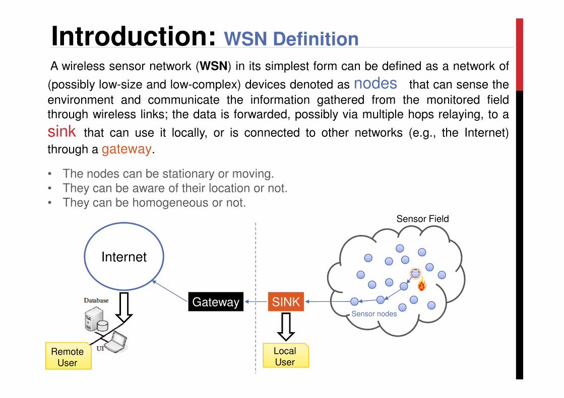
A wireless sensor network (WSN) in its simplest form can be defined as a network of
(possibly low-size and low-complex) devices denoted as nodes that can sense the
environment and communicate the information gathered from the monitored fieldthrough wireless links; the data is forwarded, possibly via multiple hops relaying, to a
sink that can use it locally, or is connected to other networks (e.g., the Internet)
through a gateway.
• The nodes can be stationary or moving. • They can be aware of their location or not. • They can be homogeneous or not.
Introduction: WSN Definition
SINK
• They can be homogeneous or not.
Gateway
Internet
Local User
Sensor Field
Sensor nodes
Remote User
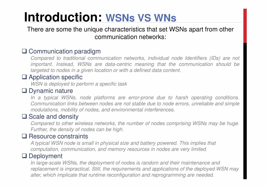
There are some the unique characteristics that set WSNs apart from other communication networks:
� Communication paradigmCompared to traditional communication networks, individual node Identifiers (IDs) are not
important. Instead, WSNs are data-centric meaning that the communication should be
targeted to nodes in a given location or with a defined data content.
� Application specificWSN is deployed to perform a specific task
� Dynamic nature
Introduction: WSNs VS WNs
� Dynamic natureIn a typical WSNs, node platforms are error-prone due to harsh operating conditions.
Communication links between nodes are not stable due to node errors, unreliable and simple
modulations, mobility of nodes, and environmental interferences.
� Scale and densityCompared to other wireless networks, the number of nodes comprising WSNs may be huge.
Further, the density of nodes can be high.
� Resource constraintsA typical WSN node is small in physical size and battery powered. This implies that
computation, communication, and memory resources in nodes are very limited.
� DeploymentIn large-scale WSNs, the deployment of nodes is random and their maintenance and
replacement is impractical. Still, the requirements and applications of the deployed WSN may
alter, which implicate that runtime reconfiguration and reprogramming are needed.
� Fault toleranceThe network functionality must be maintained even though the built-in dynamic nature and
failures of nodes due to harsh environment, depletion of batteries, or external interference
make networks prone to errors.
� LifetimeThe nodes are battery powered or the energy is scavenged from the environment and their
maintenance is difficult. Thus, energy saving and load balancing must be taken into account
in the design and implementation of WSN platforms, protocols, and applications.
� ScalabilityThe number of nodes in WSN is typically high. Thus, the WSN protocols must deal with high
densities and numbers of nodes.
Introduction: Requirements for WSNs
densities and numbers of nodes.
� RealtimeWSNs are tightly related to the real world. Therefore, strict timing constraints for sensing,
processing, and communication are present in WSNs.
� SecurityThe need for security in WSNs is evident, especially in health care, security, and military
applications. Most of the applications relay data that contain private or confidential
information.
� Production costThe number of nodes in WSNs is high, and once nodes run out of batteries they are replaced
by new ones. Further, WSNs are envisioned to be everywhere. Therefore, to make the
deployments possible, the nodes should be extremely low cost.
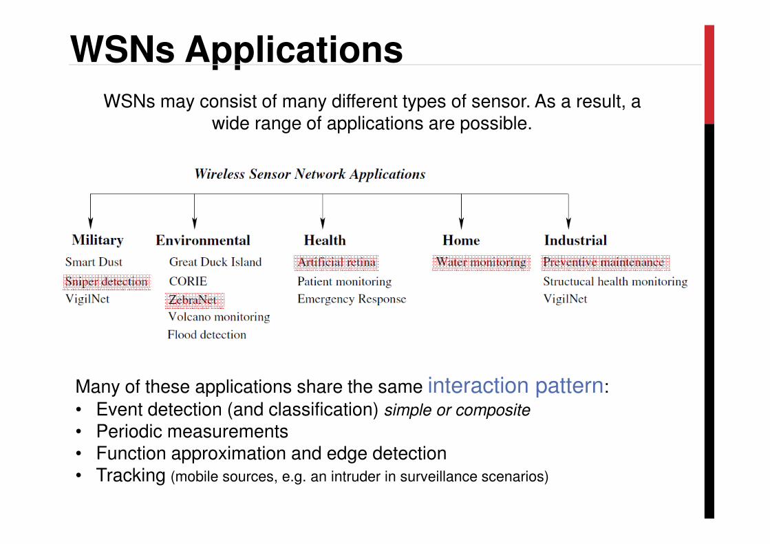
WSNs Applications
WSNs may consist of many different types of sensor. As a result, a wide range of applications are possible.
Many of these applications share the same interaction pattern:
• Event detection (and classification) simple or composite
• Periodic measurements• Function approximation and edge detection• Tracking (mobile sources, e.g. an intruder in surveillance scenarios)
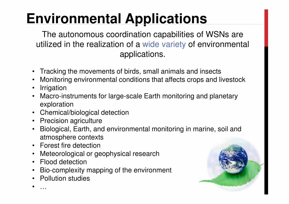
Environmental ApplicationsThe autonomous coordination capabilities of WSNs are
utilized in the realization of a wide variety of environmental applications.
• Tracking the movements of birds, small animals and insects• Monitoring environmental conditions that affects crops and livestock• Irrigation• Macro-instruments for large-scale Earth monitoring and planetary
explorationexploration• Chemical/biological detection• Precision agriculture• Biological, Earth, and environmental monitoring in marine, soil and
atmosphere contexts• Forest fire detection• Meteorological or geophysical research• Flood detection• Bio-complexity mapping of the environment• Pollution studies• …
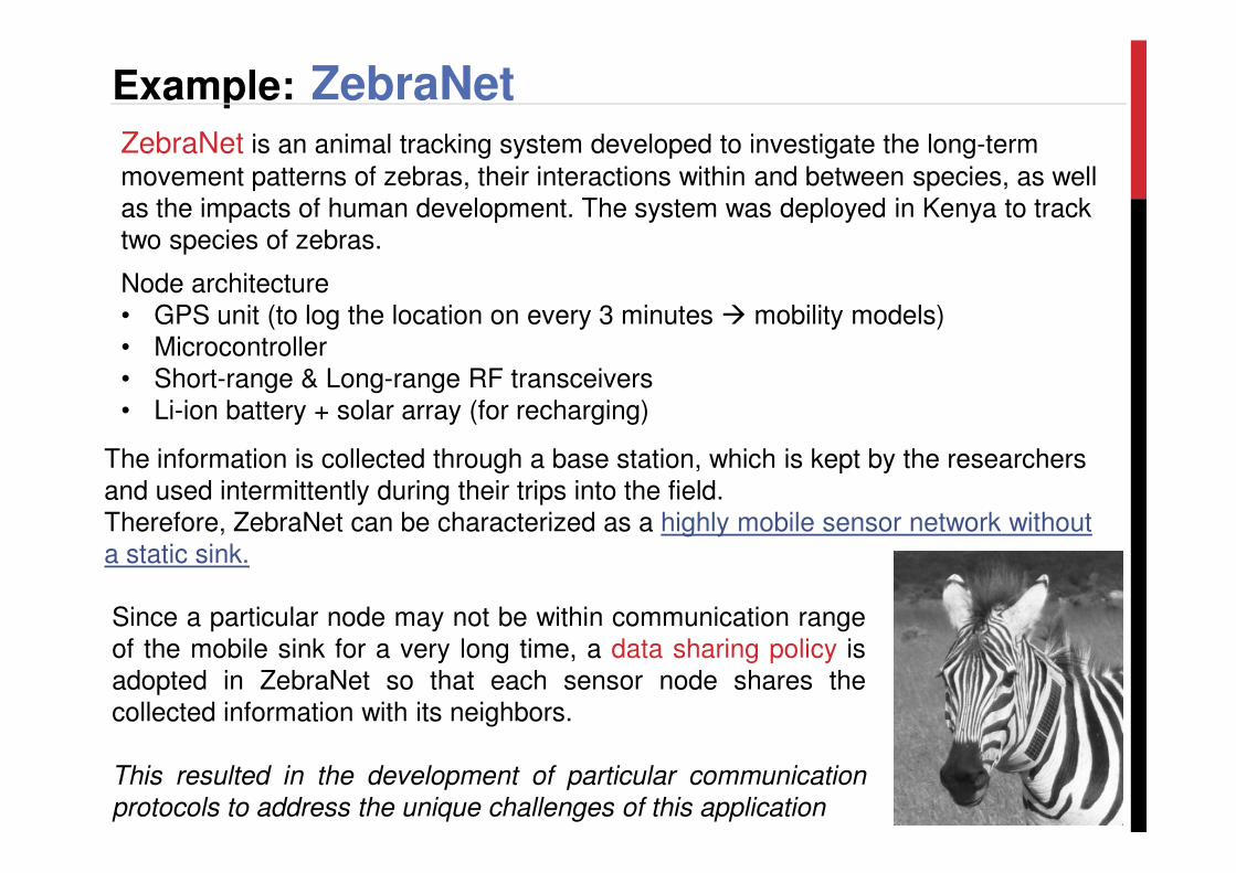
Example: ZebraNetZebraNet is an animal tracking system developed to investigate the long-term
movement patterns of zebras, their interactions within and between species, as well as the impacts of human development. The system was deployed in Kenya to track two species of zebras.
Node architecture• GPS unit (to log the location on every 3 minutes � mobility models)• Microcontroller• Short-range & Long-range RF transceivers• Li-ion battery + solar array (for recharging)
The information is collected through a base station, which is kept by the researchers and used intermittently during their trips into the field. Therefore, ZebraNet can be characterized as a highly mobile sensor network without a static sink.
Since a particular node may not be within communication rangeof the mobile sink for a very long time, a data sharing policy isadopted in ZebraNet so that each sensor node shares thecollected information with its neighbors.
This resulted in the development of particular communication
protocols to address the unique challenges of this application
Health ApplicationsThe developments in implanted biomedical devices and smart
integrated sensors make the usage ofsensor networks for biomedical applications possible.
• Provision of interfaces for the disabled• Integrated patient monitoring• Diagnostics• Drug administration in hospitals• Monitoring the movements and internal processes of insects or other • Monitoring the movements and internal processes of insects or other
small animals• Telemonitoring of human physiological data• Tracking and monitoring dotoctors and patients inside a hospital• …
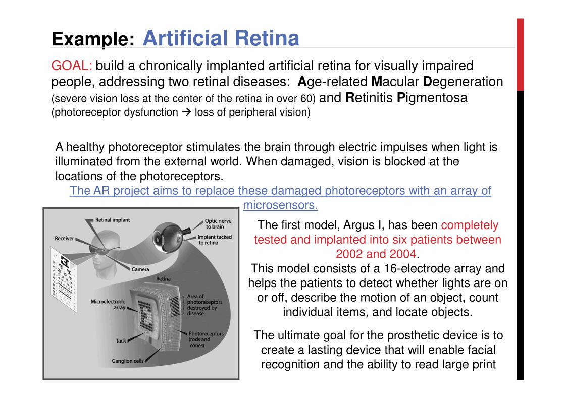
Example: Artificial RetinaGOAL: build a chronically implanted artificial retina for visually impaired people, addressing two retinal diseases: Age-related Macular Degeneration (severe vision loss at the center of the retina in over 60) and Retinitis Pigmentosa(photoreceptor dysfunction � loss of peripheral vision)
A healthy photoreceptor stimulates the brain through electric impulses when light is illuminated from the external world. When damaged, vision is blocked at the locations of the photoreceptors.
The AR project aims to replace these damaged photoreceptors with an array of microsensors.microsensors.
The ultimate goal for the prosthetic device is to create a lasting device that will enable facial recognition and the ability to read large print
The first model, Argus I, has been completely tested and implanted into six patients between
2002 and 2004. This model consists of a 16-electrode array and helps the patients to detect whether lights are on
or off, describe the motion of an object, count individual items, and locate objects.
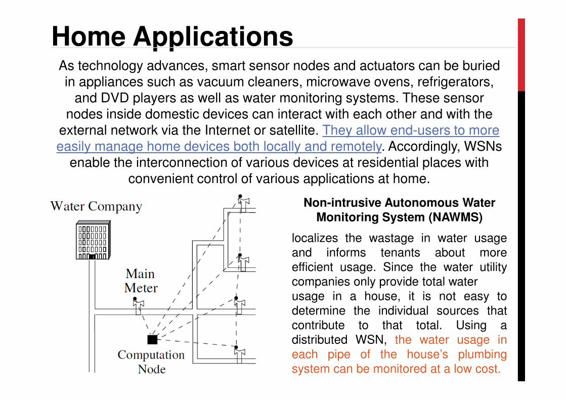
Home ApplicationsAs technology advances, smart sensor nodes and actuators can be buried in appliances such as vacuum cleaners, microwave ovens, refrigerators,
and DVD players as well as water monitoring systems. These sensor nodes inside domestic devices can interact with each other and with the
external network via the Internet or satellite. They allow end-users to more easily manage home devices both locally and remotely. Accordingly, WSNs
enable the interconnection of various devices at residential places with convenient control of various applications at home.
Non-intrusive Autonomous Water Non-intrusive Autonomous Water
Monitoring System (NAWMS)
localizes the wastage in water usageand informs tenants about moreefficient usage. Since the water utilitycompanies only provide total waterusage in a house, it is not easy todetermine the individual sources thatcontribute to that total. Using adistributed WSN, the water usage ineach pipe of the house’s plumbingsystem can be monitored at a low cost.
Industrial Applications
• monitoring material fatigue;
• managing inventory;
• monitoring product quality;
Networks of wired sensors have long been used in industrial fields such as industrial sensing and control applications, building automation, and access control. However, the cost associated with the deployment of wired sensors limits the applicability of these systems.
Instead, WSNs are a promising alternative solution for these systems due to theirease of deployment, high granularity, and high accuracy provided through battery-powered wireless communication units.
• monitoring product quality;
• constructing smart office spaces;
• environmental control of office buildings;
• robot control and guidance in automatic manufacturing environments;
• factory process control and automation;
• Smart structures with embedded sensor nodes;
• machine diagnosis;
• transportation;
• factory instrumentation;
• local control of actuators;
• vehicle tracking and detection;
• Instrumentation of semiconductor processing chambers, rotating machinery, wind
tunnels, and anechoic chambers;
• …
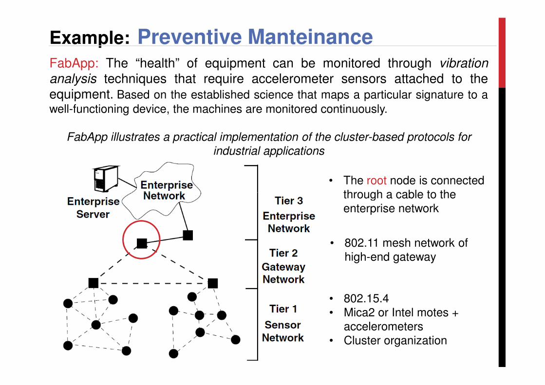
Example: Preventive ManteinanceFabApp: The “health” of equipment can be monitored through vibrationanalysis techniques that require accelerometer sensors attached to theequipment. Based on the established science that maps a particular signature to a
well-functioning device, the machines are monitored continuously.
FabApp illustrates a practical implementation of the cluster-based protocols for
industrial applications
• The root node is connected through a cable to the
• 802.15.4• Mica2 or Intel motes +
accelerometers• Cluster organization
• 802.11 mesh network of high-end gateway
through a cable to the enterprise network
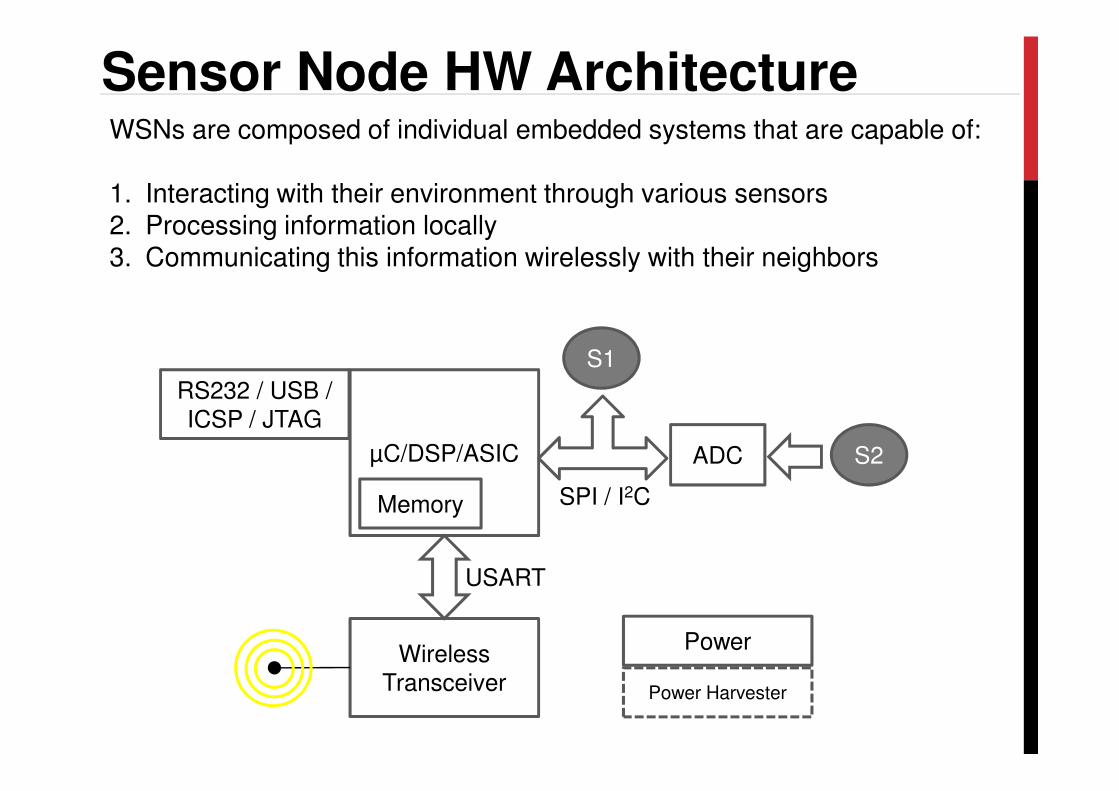
Sensor Node HW Architecture
S1
RS232 / USB /
WSNs are composed of individual embedded systems that are capable of:
1. Interacting with their environment through various sensors2. Processing information locally3. Communicating this information wirelessly with their neighbors
µC/DSP/ASIC ADC S2
SPI / I2C
Wireless Transceiver
USART
Power Harvester
Power
Memory
RS232 / USB / ICSP / JTAG
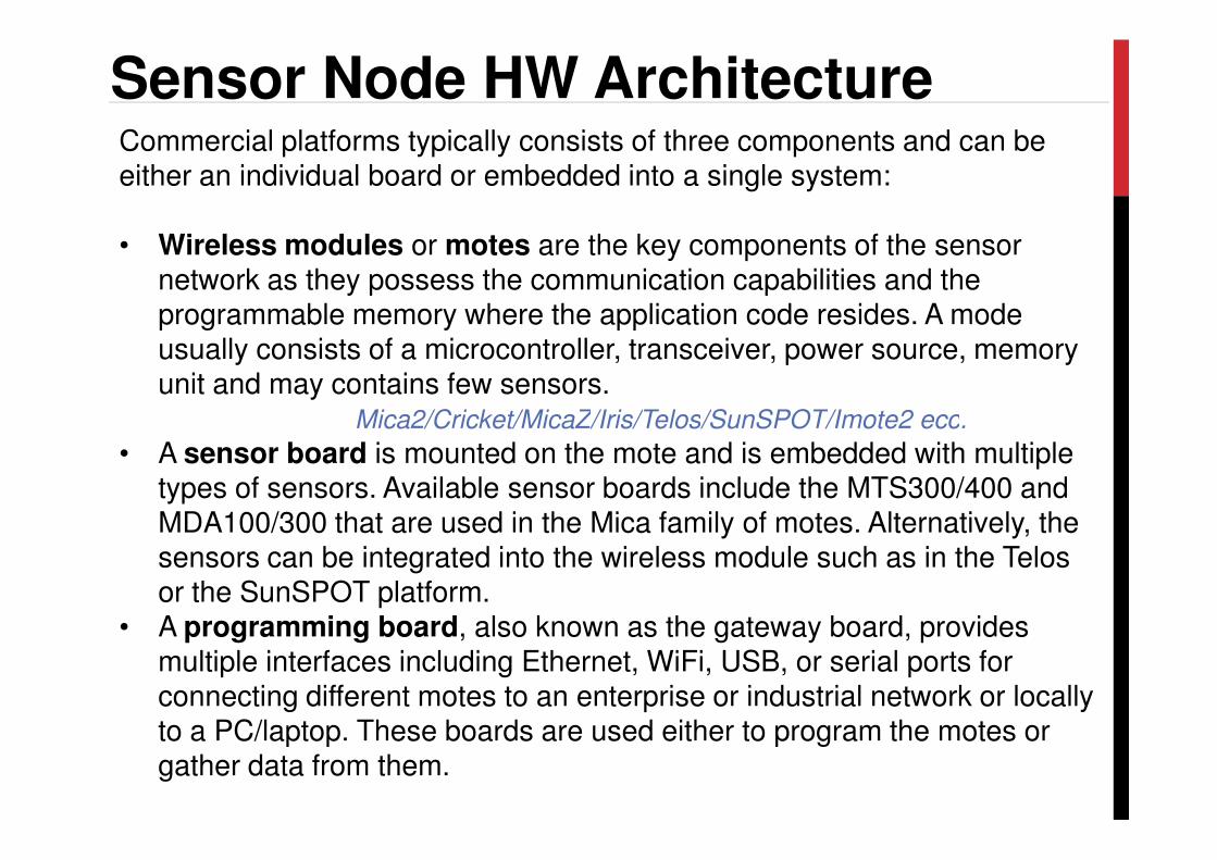
Sensor Node HW ArchitectureCommercial platforms typically consists of three components and can be either an individual board or embedded into a single system:
• Wireless modules or motes are the key components of the sensor network as they possess the communication capabilities and the programmable memory where the application code resides. A mode usually consists of a microcontroller, transceiver, power source, memory unit and may contains few sensors.
Mica2/Cricket/MicaZ/Iris/Telos/SunSPOT/Imote2 ecc.Mica2/Cricket/MicaZ/Iris/Telos/SunSPOT/Imote2 ecc.
• A sensor board is mounted on the mote and is embedded with multiple types of sensors. Available sensor boards include the MTS300/400 and MDA100/300 that are used in the Mica family of motes. Alternatively, the sensors can be integrated into the wireless module such as in the Telosor the SunSPOT platform.
• A programming board, also known as the gateway board, provides multiple interfaces including Ethernet, WiFi, USB, or serial ports for connecting different motes to an enterprise or industrial network or locally to a PC/laptop. These boards are used either to program the motes or gather data from them.
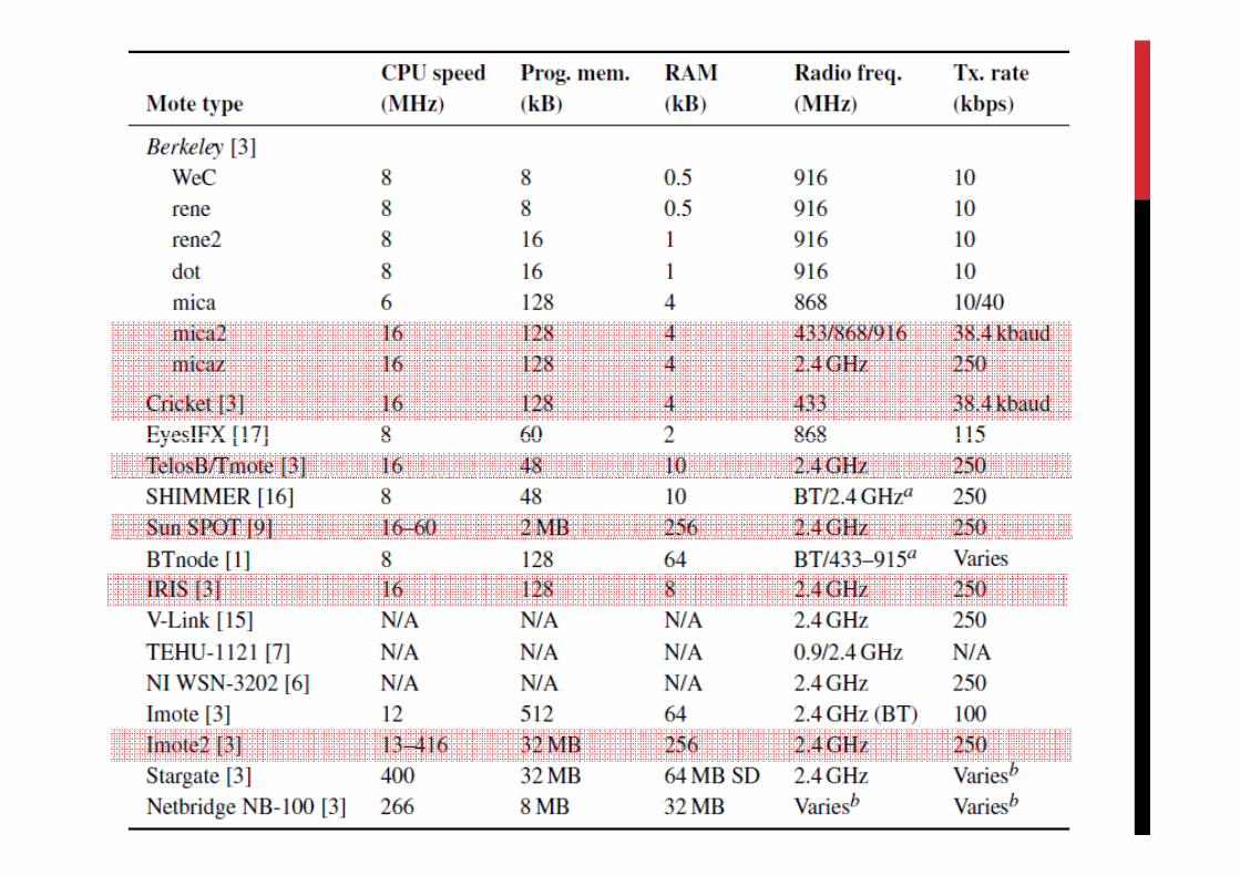
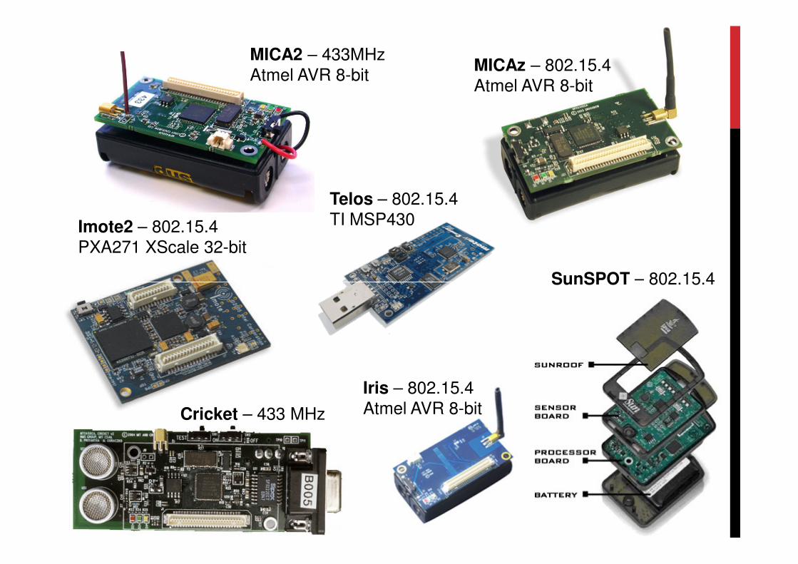
MICA2 – 433MHzAtmel AVR 8-bit
MICAz – 802.15.4Atmel AVR 8-bit
Telos – 802.15.4TI MSP430Imote2 – 802.15.4
PXA271 XScale 32-bit
SunSPOT – 802.15.4
Iris – 802.15.4Atmel AVR 8-bitCricket – 433 MHz
SunSPOT – 802.15.4
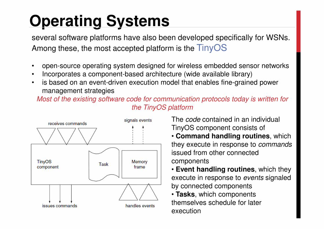
Operating Systemsseveral software platforms have also been developed specifically for WSNs.
Among these, the most accepted platform is the TinyOS
• open-source operating system designed for wireless embedded sensor networks• Incorporates a component-based architecture (wide available library)• is based on an event-driven execution model that enables fine-grained power
management strategiesMost of the existing software code for communication protocols today is written for
the TinyOS platform
The code contained in an individual TinyOS component consists of• Command handling routines, which they execute in response to commands
issued from other connected components • Event handling routines, which they execute in response to events signaled by connected components• Tasks, which components themselves schedule for later execution
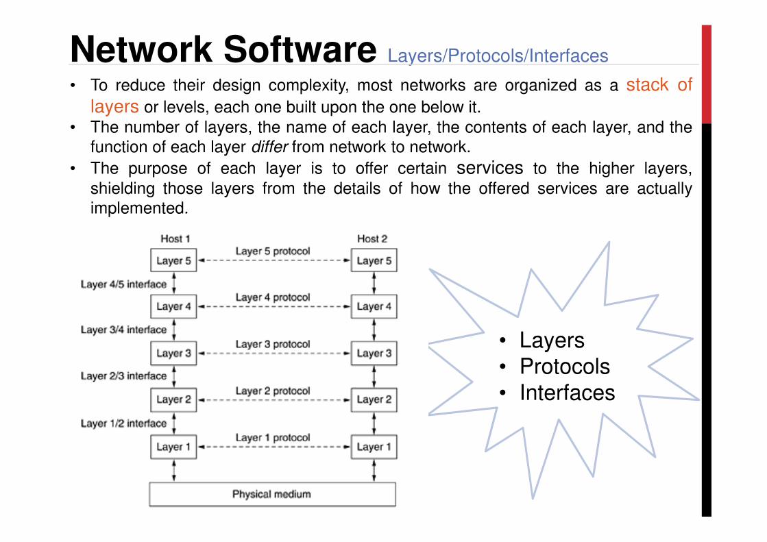
Network Software Layers/Protocols/Interfaces
• To reduce their design complexity, most networks are organized as a stack oflayers or levels, each one built upon the one below it.
• The number of layers, the name of each layer, the contents of each layer, and thefunction of each layer differ from network to network.
• The purpose of each layer is to offer certain services to the higher layers,
shielding those layers from the details of how the offered services are actuallyimplemented.
• Layers• Protocols• Interfaces
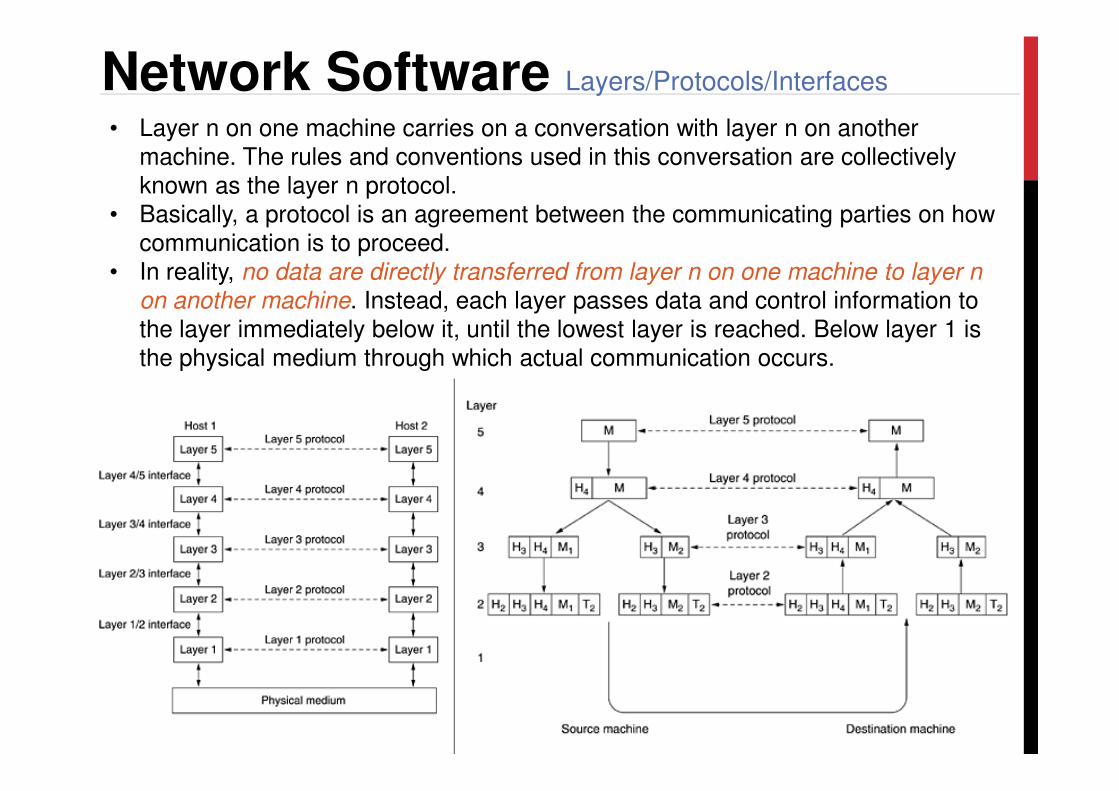
• Layer n on one machine carries on a conversation with layer n on another machine. The rules and conventions used in this conversation are collectively known as the layer n protocol.
• Basically, a protocol is an agreement between the communicating parties on how communication is to proceed.
• In reality, no data are directly transferred from layer n on one machine to layer n
on another machine. Instead, each layer passes data and control information to the layer immediately below it, until the lowest layer is reached. Below layer 1 is the physical medium through which actual communication occurs.
Network Software Layers/Protocols/Interfaces
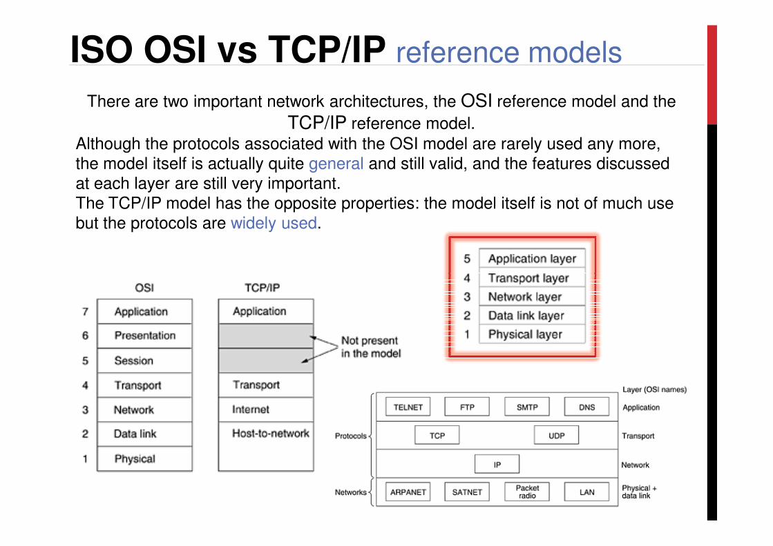
ISO OSI vs TCP/IP reference models
There are two important network architectures, the OSI reference model and the
TCP/IP reference model.
Although the protocols associated with the OSI model are rarely used any more, the model itself is actually quite general and still valid, and the features discussed at each layer are still very important. The TCP/IP model has the opposite properties: the model itself is not of much use but the protocols are widely used.
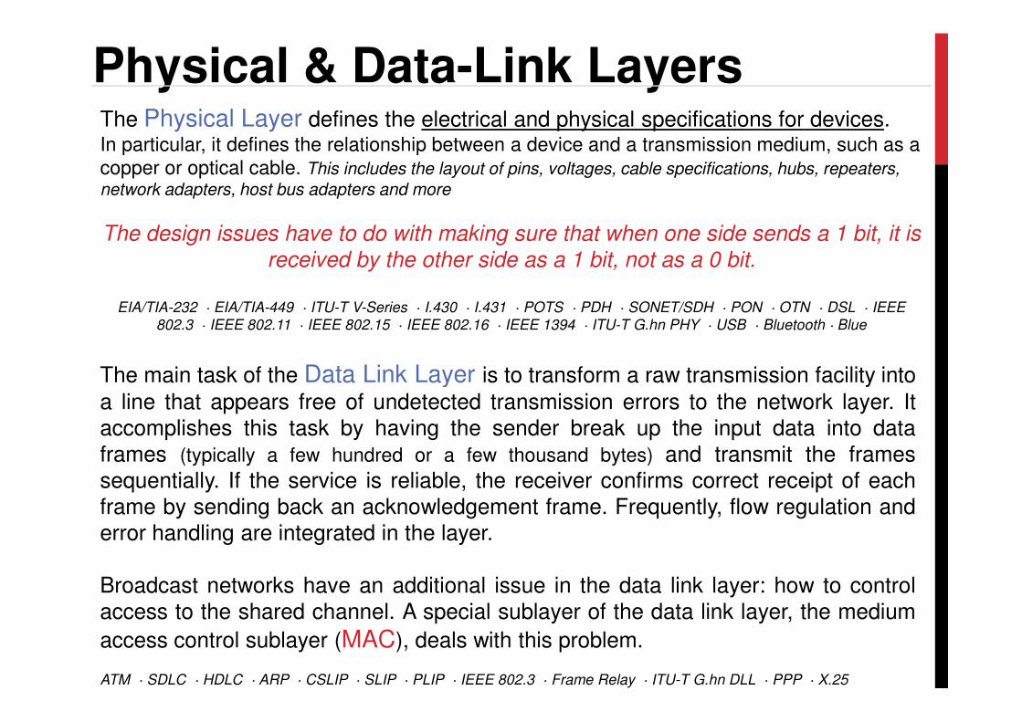
Physical & Data-Link LayersThe Physical Layer defines the electrical and physical specifications for devices. In particular, it defines the relationship between a device and a transmission medium, such as a
copper or optical cable. This includes the layout of pins, voltages, cable specifications, hubs, repeaters,
network adapters, host bus adapters and more
The design issues have to do with making sure that when one side sends a 1 bit, it is
received by the other side as a 1 bit, not as a 0 bit.
EIA/TIA-232 · EIA/TIA-449 · ITU-T V-Series · I.430 · I.431 · POTS · PDH · SONET/SDH · PON · OTN · DSL · IEEE
802.3 · IEEE 802.11 · IEEE 802.15 · IEEE 802.16 · IEEE 1394 · ITU-T G.hn PHY · USB · Bluetooth · Blue
Data Link LayerThe main task of the Data Link Layer is to transform a raw transmission facility into
a line that appears free of undetected transmission errors to the network layer. Itaccomplishes this task by having the sender break up the input data into dataframes (typically a few hundred or a few thousand bytes) and transmit the framessequentially. If the service is reliable, the receiver confirms correct receipt of eachframe by sending back an acknowledgement frame. Frequently, flow regulation anderror handling are integrated in the layer.
Broadcast networks have an additional issue in the data link layer: how to controlaccess to the shared channel. A special sublayer of the data link layer, the medium
access control sublayer (MAC), deals with this problem.
ATM · SDLC · HDLC · ARP · CSLIP · SLIP · PLIP · IEEE 802.3 · Frame Relay · ITU-T G.hn DLL · PPP · X.25
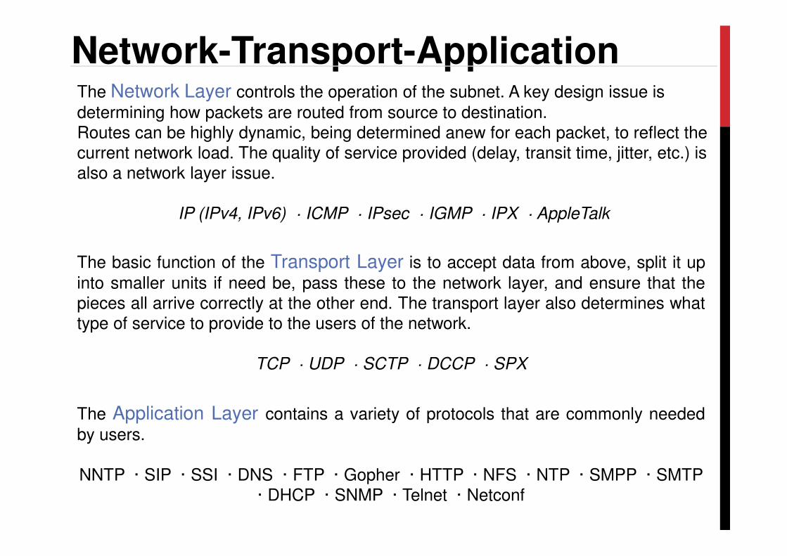
Network-Transport-ApplicationThe Network Layer controls the operation of the subnet. A key design issue is
determining how packets are routed from source to destination. Routes can be highly dynamic, being determined anew for each packet, to reflect the current network load. The quality of service provided (delay, transit time, jitter, etc.) is also a network layer issue.
IP (IPv4, IPv6) · ICMP · IPsec · IGMP · IPX · AppleTalk
The basic function of the Transport Layer is to accept data from above, split it up
into smaller units if need be, pass these to the network layer, and ensure that theinto smaller units if need be, pass these to the network layer, and ensure that thepieces all arrive correctly at the other end. The transport layer also determines whattype of service to provide to the users of the network.
TCP · UDP · SCTP · DCCP · SPX
The Application Layer contains a variety of protocols that are commonly needed
by users.
NNTP · SIP · SSI · DNS · FTP · Gopher · HTTP · NFS · NTP · SMPP · SMTP · DHCP · SNMP · Telnet · Netconf

IEEE 802.15.4IEEE 802.15.4 is a standard which specifies the physical layer and media access control for low-rate wireless personal area networks (LR-WPANs). The standard defines the channel access mechanism, acknowledged frame delivery, network association and disassociationIt is maintained by the IEEE 802.15 working group.
• Three DSSS PHY layers are specified:
• 2.4 GHz ISM (Global, O-QPSK modulation � 250 kbit/sec, 16 ch)
• 915 MHz (America, BPSK modulation � 40 kbit/sec, 10 ch)
• 868 MHz (Europe, BPSK modulation) � 20 kbit/sec, 1 ch)
• The MAC layer provides communication for star, mesh and cluster-three • The MAC layer provides communication for star, mesh and cluster-three topologies with controllers
• The transmission range of the nodes is assumed to be 10…100m• Three types of network devices are supported:
• PAN coordinatorInitiates the network and often operates as a gateway to other networks.
Each PAN must have exactly one PAN coordinator.
• CoordinatorsCoordinators collaborate with each other for executing data routing and network self-
organization operations
• Devices Do not have data routing capability and can communicate only with coordinators
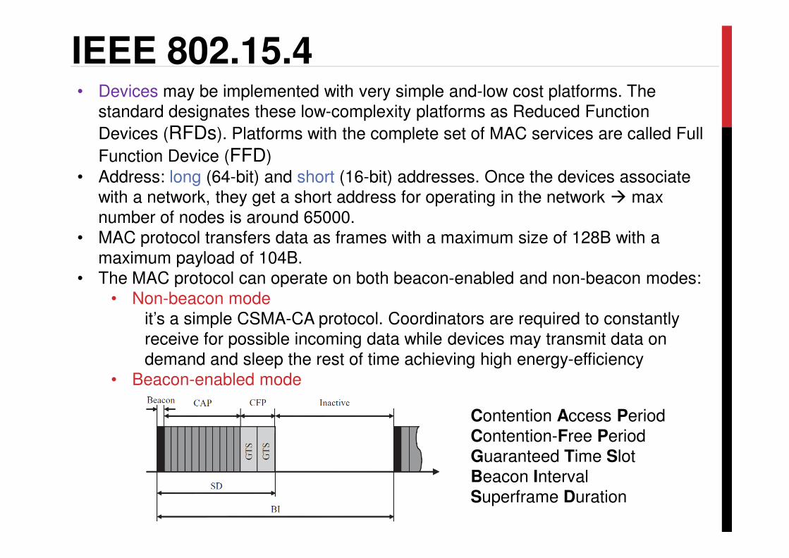
IEEE 802.15.4• Devices may be implemented with very simple and-low cost platforms. The
standard designates these low-complexity platforms as Reduced Function
Devices (RFDs). Platforms with the complete set of MAC services are called Full
Function Device (FFD)
• Address: long (64-bit) and short (16-bit) addresses. Once the devices associate with a network, they get a short address for operating in the network � max number of nodes is around 65000.
• MAC protocol transfers data as frames with a maximum size of 128B with a maximum payload of 104B.
• The MAC protocol can operate on both beacon-enabled and non-beacon modes:• The MAC protocol can operate on both beacon-enabled and non-beacon modes:• Non-beacon mode
it’s a simple CSMA-CA protocol. Coordinators are required to constantly receive for possible incoming data while devices may transmit data on demand and sleep the rest of time achieving high energy-efficiency
• Beacon-enabled mode
Contention Access PeriodContention-Free PeriodGuaranteed Time SlotBeacon IntervalSuperframe Duration
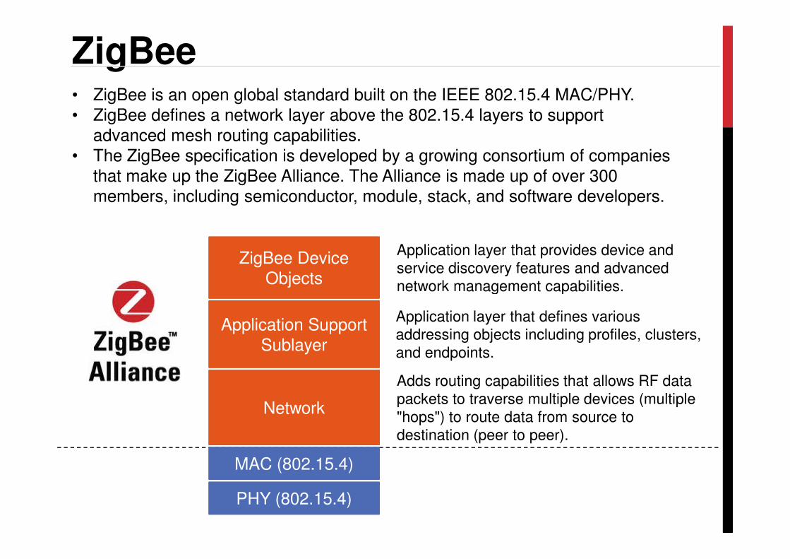
ZigBee• ZigBee is an open global standard built on the IEEE 802.15.4 MAC/PHY. • ZigBee defines a network layer above the 802.15.4 layers to support
advanced mesh routing capabilities. • The ZigBee specification is developed by a growing consortium of companies
that make up the ZigBee Alliance. The Alliance is made up of over 300 members, including semiconductor, module, stack, and software developers.
ZigBee Device Objects
Application layer that provides device and
service discovery features and advanced
network management capabilities.
PHY (802.15.4)
MAC (802.15.4)
Network
Adds routing capabilities that allows RF data
packets to traverse multiple devices (multiple
"hops") to route data from source to
destination (peer to peer).
Application Support Sublayer
Application layer that defines various
addressing objects including profiles, clusters,
and endpoints.
Objects network management capabilities.
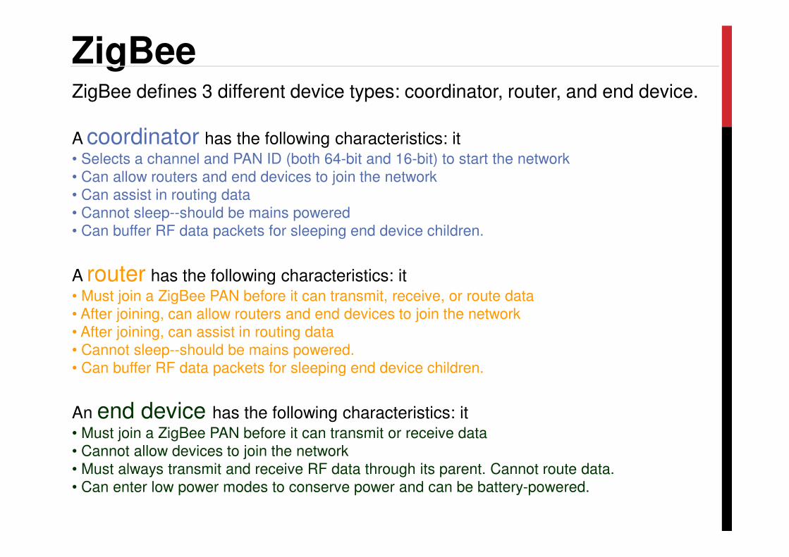
ZigBeeZigBee defines 3 different device types: coordinator, router, and end device.
A coordinator has the following characteristics: it• Selects a channel and PAN ID (both 64-bit and 16-bit) to start the network
• Can allow routers and end devices to join the network
• Can assist in routing data
• Cannot sleep--should be mains powered
• Can buffer RF data packets for sleeping end device children.
A router has the following characteristics: itA router has the following characteristics: it• Must join a ZigBee PAN before it can transmit, receive, or route data
• After joining, can allow routers and end devices to join the network
• After joining, can assist in routing data
• Cannot sleep--should be mains powered.
• Can buffer RF data packets for sleeping end device children.
An end device has the following characteristics: it• Must join a ZigBee PAN before it can transmit or receive data
• Cannot allow devices to join the network
• Must always transmit and receive RF data through its parent. Cannot route data.
• Can enter low power modes to conserve power and can be battery-powered.
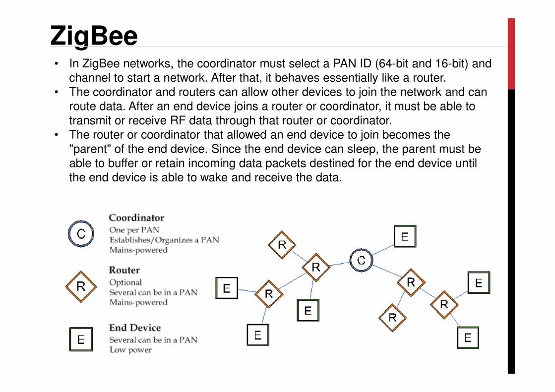
ZigBee• In ZigBee networks, the coordinator must select a PAN ID (64-bit and 16-bit) and
channel to start a network. After that, it behaves essentially like a router. • The coordinator and routers can allow other devices to join the network and can
route data. After an end device joins a router or coordinator, it must be able to transmit or receive RF data through that router or coordinator.
• The router or coordinator that allowed an end device to join becomes the "parent" of the end device. Since the end device can sleep, the parent must be able to buffer or retain incoming data packets destined for the end device until the end device is able to wake and receive the data.
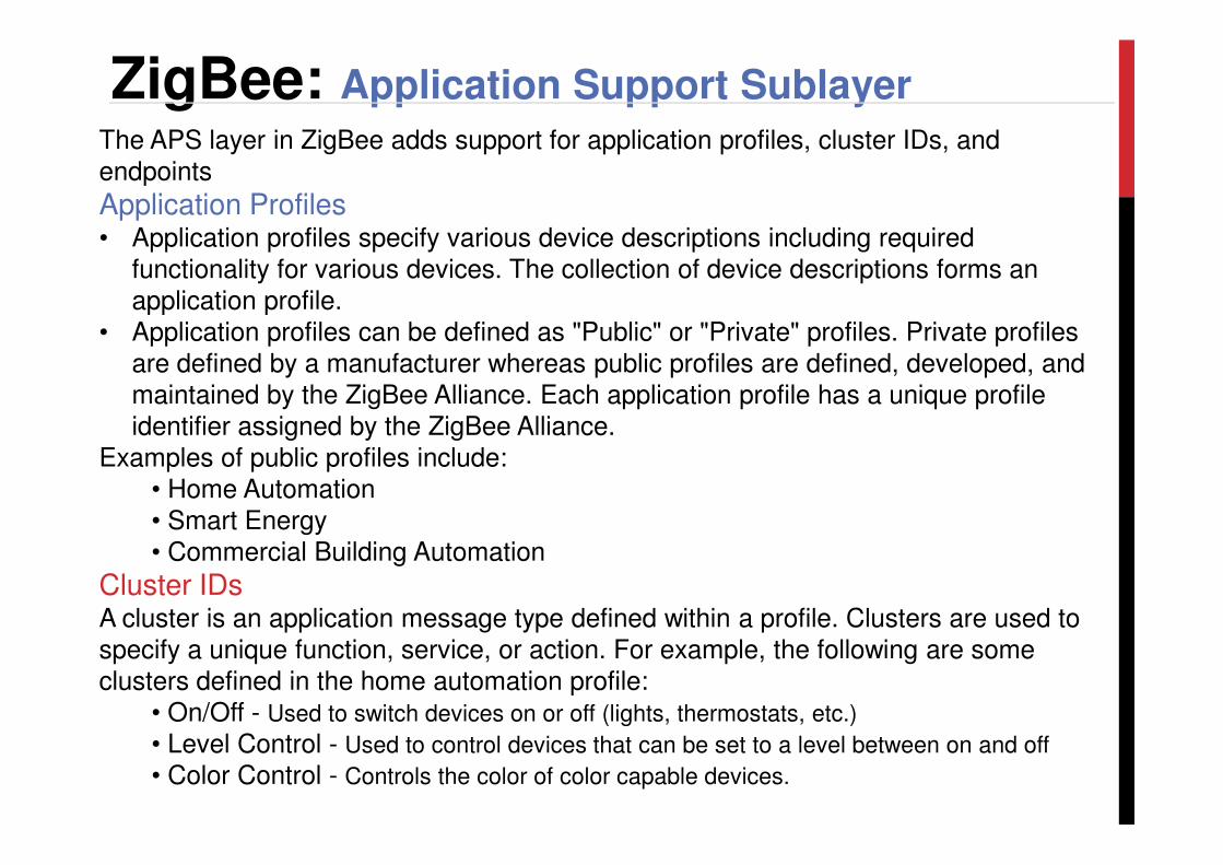
ZigBee: Application Support Sublayer
The APS layer in ZigBee adds support for application profiles, cluster IDs, and endpoints
Application Profiles• Application profiles specify various device descriptions including required
functionality for various devices. The collection of device descriptions forms an application profile.
• Application profiles can be defined as "Public" or "Private" profiles. Private profiles are defined by a manufacturer whereas public profiles are defined, developed, and maintained by the ZigBee Alliance. Each application profile has a unique profile identifier assigned by the ZigBee Alliance. identifier assigned by the ZigBee Alliance.
Examples of public profiles include:• Home Automation• Smart Energy• Commercial Building Automation
Cluster IDsA cluster is an application message type defined within a profile. Clusters are used to specify a unique function, service, or action. For example, the following are some clusters defined in the home automation profile:
• On/Off - Used to switch devices on or off (lights, thermostats, etc.)
• Level Control - Used to control devices that can be set to a level between on and off
• Color Control - Controls the color of color capable devices.

ZigBee: Application Support Sublayer
Endpoints• The APS layer includes supports for endpoints. An endpoint can be thought of as a
running application, similar to a TCP/IP port. • A single device can support one or more endpoints. • Each application endpoint is identified by a 1-byte value, ranging from 1 to 240. • Each defined endpoint on a device is tied to an application profile. A device could, for example, implement one endpoint that supports a Smart Energy load
controller, and another endpoint that supports other functionality on a private profile.
The ZDO (endpoint 0) supports the discovery and management capabilities of the The ZDO (endpoint 0) supports the discovery and management capabilities of the
ZigBee Device Profile (ID 0x0000). This profile is implemented on all ZigBee devices. Device Profile defines many device and service discovery features and network management capabilities.
A complete listing of all ZDP services is included in the ZigBee specification. Each service has an associated cluster ID.
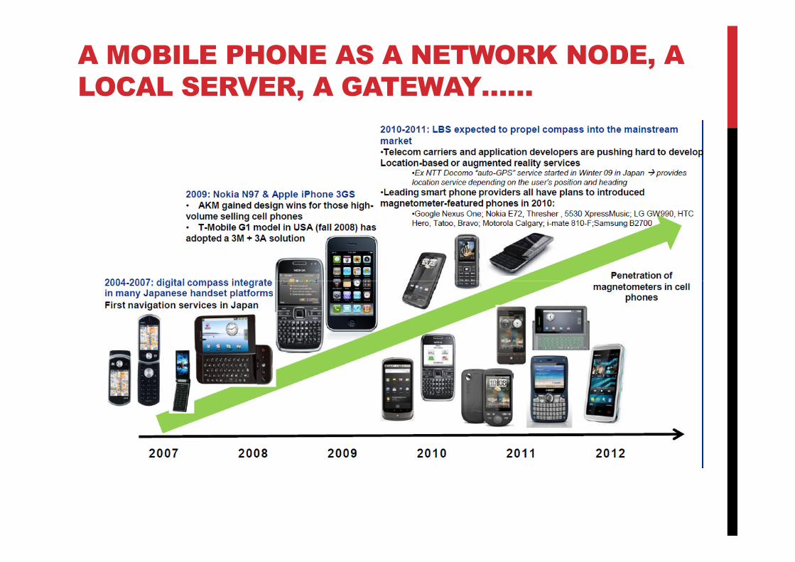
A MOBILE PHONE AS A NETWORK NODE, A
LOCAL SERVER, A GATEWAY……

….AN EXAMPLE…
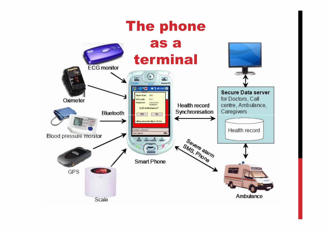
The phone
as a
terminal
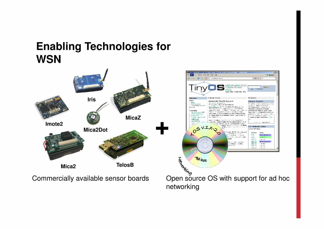
Iris
+
Enabling Technologies for
WSN
Mica2 TelosB
Imote2Mica2Dot
MicaZ
Commercially available sensor boards Open source OS with support for ad hoc networking
+
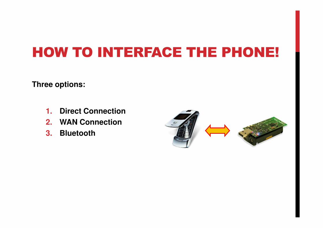
HOW TO INTERFACE THE PHONE!
Three options:
1. Direct Connection1. Direct Connection
2. WAN Connection
3. Bluetooth
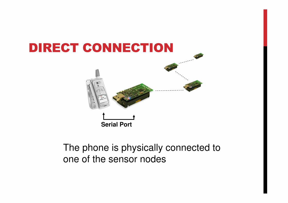
DIRECT CONNECTION
Serial Port
The phone is physically connected to
one of the sensor nodes

WAN CONNECTIONGPRS
WiFiInternet
WEB TCP/IPServer
The phone uses a WAN connection to access the WSN information
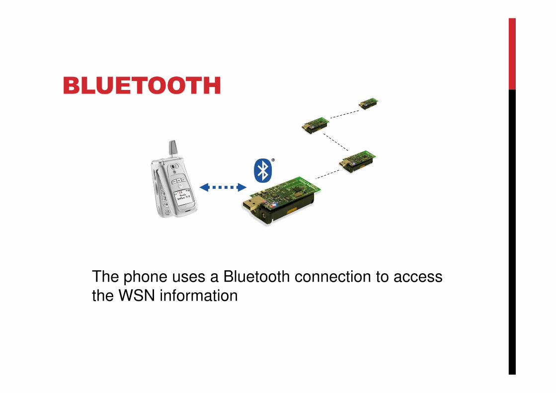
BLUETOOTH
The phone uses a Bluetooth connection to access the WSN information

Thermal:
• Temperature/heat sensors
Electromagnetic:
• Electrical resistance/voltage/power sensors, magnetism sensors, metal detectors, RADAR
Mechanical:
• Acceleration, position, pressure, switch, liquid sensors
Chemical:
Sensor Types
Chemical:
• Odor (smell) sensor, oxygen sensors
Optical radiation:
• Light sensors, infra-red sensor, proximity sensor
Acoustic: Sound sensors
Motion sensors:
• Radar gun, speedometer, tachometer, odometer
Orientation sensors: Gyroscope
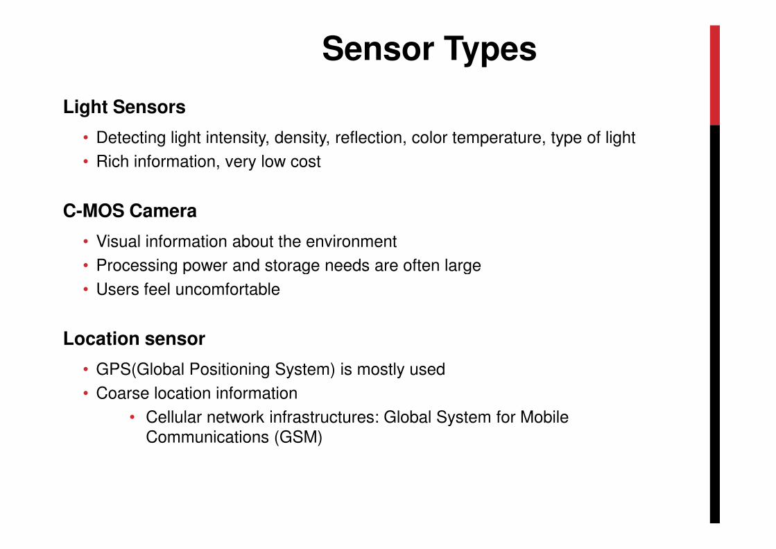
Light Sensors
• Detecting light intensity, density, reflection, color temperature, type of light
• Rich information, very low cost
C-MOS Camera
• Visual information about the environment
• Processing power and storage needs are often large
Sensor Types
• Users feel uncomfortable
Location sensor
• GPS(Global Positioning System) is mostly used
• Coarse location information
• Cellular network infrastructures: Global System for Mobile Communications (GSM)
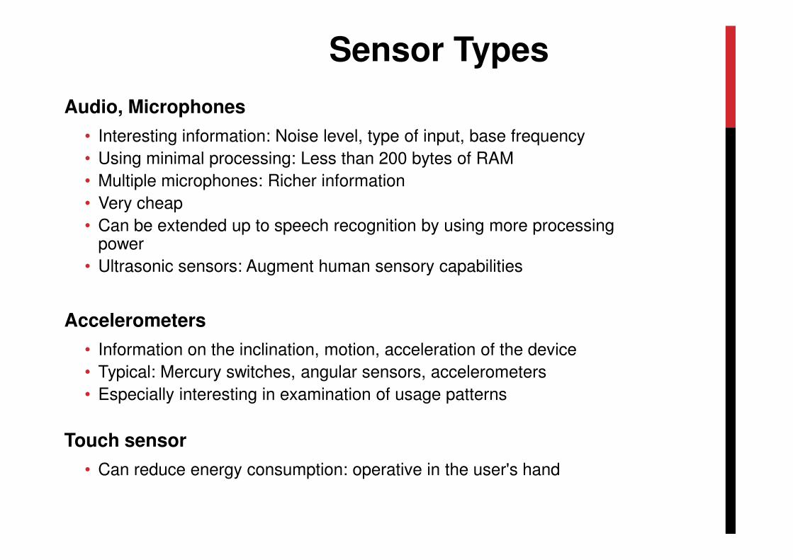
Audio, Microphones
• Interesting information: Noise level, type of input, base frequency
• Using minimal processing: Less than 200 bytes of RAM
• Multiple microphones: Richer information
• Very cheap
• Can be extended up to speech recognition by using more processing power
• Ultrasonic sensors: Augment human sensory capabilities
Sensor Types
Accelerometers
• Information on the inclination, motion, acceleration of the device
• Typical: Mercury switches, angular sensors, accelerometers
• Especially interesting in examination of usage patterns
Touch sensor
• Can reduce energy consumption: operative in the user's hand
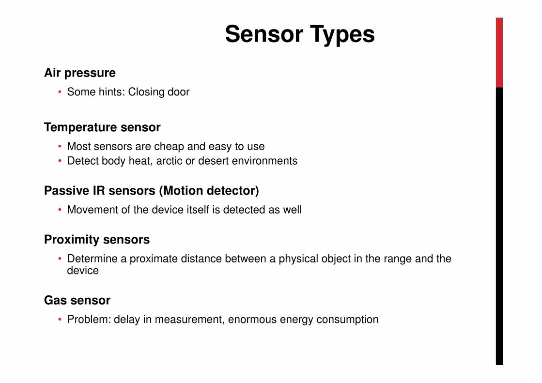
Air pressure
• Some hints: Closing door
Temperature sensor
• Most sensors are cheap and easy to use
• Detect body heat, arctic or desert environments
Passive IR sensors (Motion detector)
Sensor Types
Passive IR sensors (Motion detector)
• Movement of the device itself is detected as well
Proximity sensors
• Determine a proximate distance between a physical object in the range and the device
Gas sensor
• Problem: delay in measurement, enormous energy consumption
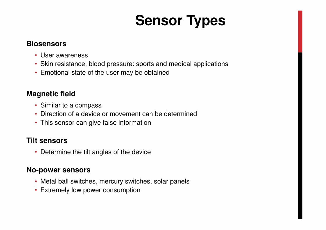
Biosensors
• User awareness
• Skin resistance, blood pressure: sports and medical applications
• Emotional state of the user may be obtained
Magnetic field
• Similar to a compass
• Direction of a device or movement can be determined
Sensor Types
• Direction of a device or movement can be determined
• This sensor can give false information
Tilt sensors
• Determine the tilt angles of the device
No-power sensors
• Metal ball switches, mercury switches, solar panels
• Extremely low power consumption
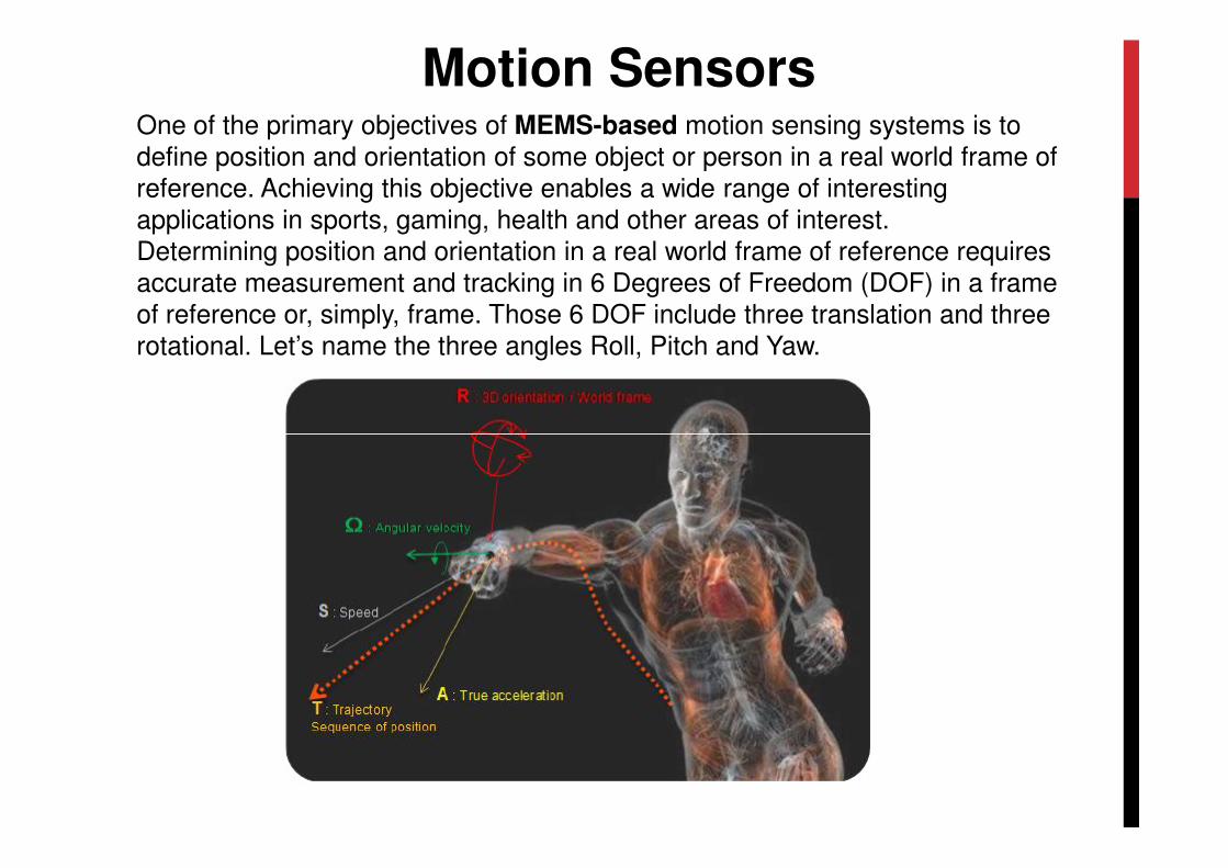
One of the primary objectives of MEMS-based motion sensing systems is to define position and orientation of some object or person in a real world frame of reference. Achieving this objective enables a wide range of interesting applications in sports, gaming, health and other areas of interest. Determining position and orientation in a real world frame of reference requires accurate measurement and tracking in 6 Degrees of Freedom (DOF) in a frame of reference or, simply, frame. Those 6 DOF include three translation and three rotational. Let’s name the three angles Roll, Pitch and Yaw.
Motion Sensors
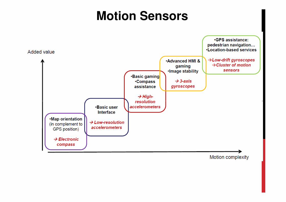
Motion Sensors