wireless instrumentation: phoenix contact rad-ism · pdf file2-wire device 4-20ma current loop...
TRANSCRIPT
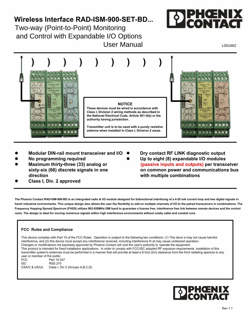
Wireless Interface RAD-ISM-900-SET-BD...Two-way (Point-to-Point) Monitoringand Control with Expandable I/O Options
User Manual L001662
Rev 1.1
l Modular DIN-rail mount transceiver and I/Ol No programming requiredl Maximum thirty-three (33) analog or
sixty-six (66) discrete signals in onedirection
l Class I, Div. 2 approved
l Dry contact RF LINK diagnostic outputl Up to eight (8) expandable I/O modules (passive inputs and outputs) per transceiver
on common power and communications buswith multiple combinations
) ) ) ) ) ) ) ) )
FCC Rules and Compliance
This device complies with Part 15 of the FCC Rules. Operation is subject to the following two conditions: (1) This devic e may not cause harmfulinterference, and (2) this device must accept any interference received, including interference th at may cause undesired operation.Changes or modifications not expressly approved by Phoenix Contact will void the user's authority to operate the equipment.This product is intended for fixed installation applications. In order to comply with FCC/ISC adopted RF exposure requirements, installation of thistransmitter system's antennas must be performed in a manner that will provide at least a 6 foot (2m) clearance from the front radiating aperture to anyuser or member of the public.FCC Part 15.247ISC RSS 210CSA/C & US/UL Class I, Div 2 (Groups A,B,C,D)
The Phoenix Contact RAD-ISM-900-BD is an intergrated radio & I/O module designed for bidirectional interfacing of a 4-20 mA current loop and two digital signals in
harsh industrial environments. This unique design also allows the user the flexibility to add on multiple channels of I/O to the paired transceivers in combinations. The
Frequency Hopping Spread Spectrum (FHSS) utilizes 902-928MHz ISM band to guarantee a license free, interference free link between remote devices and the control
room. The design is ideal for moving numerous signals within high interference environments without costly cable and conduit runs.
NOTICEThese devices must be wired in accordance withClass I, Division 2 wiring methods as described inthe National Electrical Code, Article 501-4(b) or theauthority having jurisdiction.
Transmitter unit is to be used with a purely resistiveantenna when installed in Class I, Division 2 areas.

MIN
I-PS-120-230AC
/24DC
/0.65
9 10 11 12
13 14 15 16
OUT 24VDC- -- -
++++
IN 120-230VAC
L(+) N/C N/C N(-)
Power
24VDC
Power Supply
Input Example 1
2-Wire Device 4-20mA Current Loop
RAD-ISM-900-BD TransceiverAnalog and Discrete INPUTS
(-) (+)
MIN
I-PS-120-230AC
/24DC
/0.65
9 10 11 12
13 14 15 16
OUT 24VDC- -- -
++++
1 2 3 4
IN 120-230VAC
L(+) N/C N/C N(-)
Power
24VDC
Power Supply
Discrete Input1
Discrete Input2
1 432
5 6 7 8
9 121110
13 14 15 16
MIN
I-PS-120-230AC
/24DC
/0.659 10 11 12
13 14 15 16
OUT 24VDC- -- -
++++
IN 120-230VAC
L(+) N/C N/C N(-)
Power
1 432
5 6 7 8
(-) (+)24VD
C Pow
er Supply
(-) (+)
1 432
5 6 7 8
4-Wire Device 4-20mA Current Loop
3-Wire Device 4-20mA Current Loop
Input Example 3
Input Example 2
4-20mA DeviceCurrentSource
Floating
+-
4-20mA Device
SignalCommon
CurrentSource
+-
Floating
4-20mA Device
ExternalVoltageSource
+
-
Floating
2
2867092
2867092
2867092

RAD-ISM-900-BD TransceiverBlock Diagram
1 2 3 4 5 6 7 89
10
11
12
13
14
15
162B
2A
A
B
1B
1A+-
1A
1B
2A
2B
+-
+-
Ground
4-20mA In
4-20 mA In
4-20mA Out
4-20mA Out
9 to 30VDC Power
RF Link B
RF Link A
Discrete Input 1
Discrete Input 1
Discrete Input 2
Discrete Input 2
Discrete Output 1
Discrete Output 1
Discrete Output 2
Discrete Output 2
RF Link and ChoosingOutput States
RAD-ISM-900-BD TransceiverAnalog and Discrete OUTPUTS
RF Link Output
The Link Status contact on the RAD-ISM-900-BD isNormally Open (NO) and closes when the radioestablishes an RF Link. It can be used to switcheither a STATUS light or a FAULT indicator.
Selecting State of Outputs upon Loss of RF Link
The default state upon loss of RF signal for theanalog and discrete outputs is MAINTAIN LASTSTATE. They may be wired in series with the RFLink contact to provide a FAULT OFF when RF Linkis terminated.
(-) (+)
MIN
I-PS-120-230AC
/24DC
/0.65
9 10 11 12
13 14 15 16
OUT 24VDC- -- -
++++
1 2 3 4
IN 120-230VAC
L(+) N/C N/C N(-)
Power
Discrete Output 1
1 432
5 6 7 8
9 121110
13 14 15 16
+ -
Analog Output(4-20mA)
Link Status Indicator
24VDC
Power Supply
+
-
Discrete Output 2No connection shown
RAD-ISM-900-BD TransceiverOutput Examples
RF
Supressor
Power Supply120VAC 5A
Max.
M
3
2867092
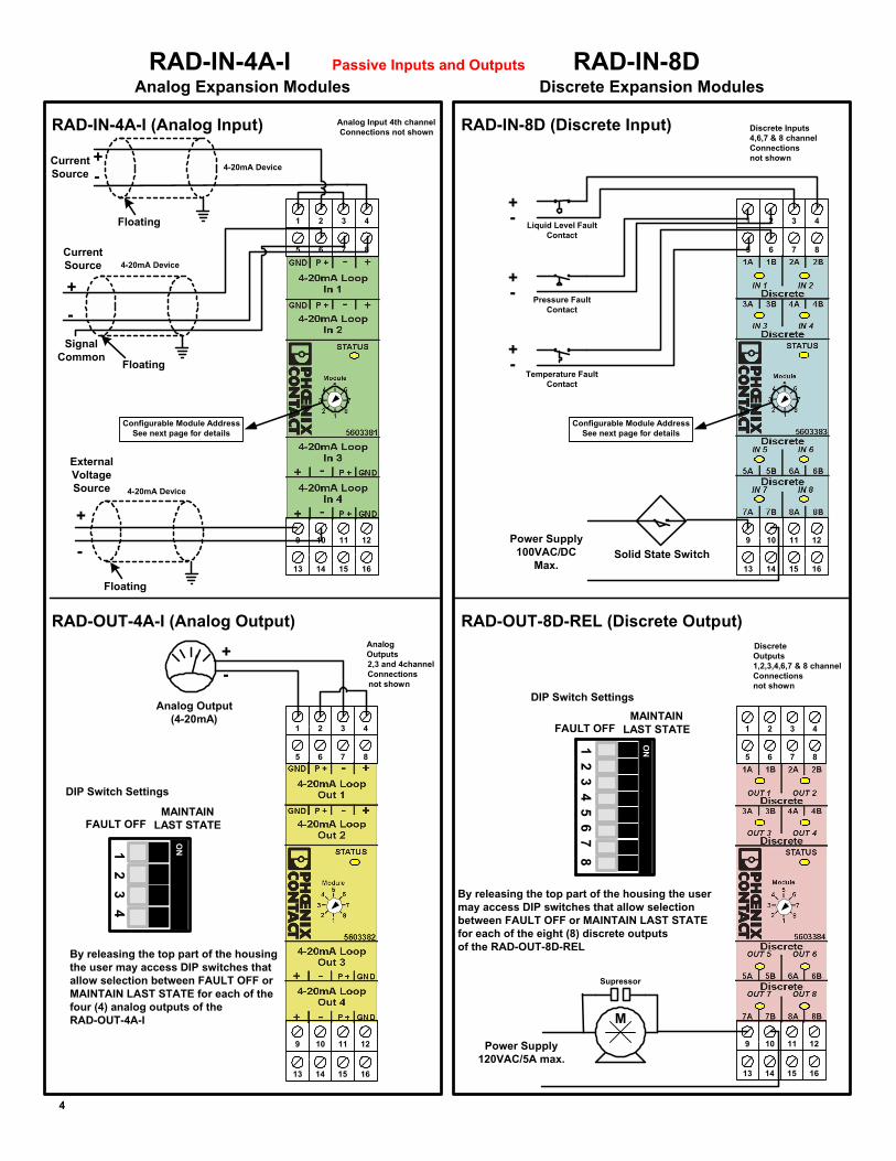
RAD-IN-4A-I Passive Inputs and Outputs
Analog Expansion ModulesRAD-IN-8D
Discrete Expansion Modules
RAD-IN-4A-I (Analog Input) Analog Input 4th channelConnections not shown
1 432
5 6 7 8
9 121110
13 14 15 16
RAD-OUT-4A-I (Analog Output)
By releasing the top part of the housingthe user may access DIP switches thatallow selection between FAULT OFF orMAINTAIN LAST STATE for each of thefour (4) analog outputs of the RAD-OUT-4A-I
Analog Output(4-20mA)
AnalogOutputs2,3 and 4channelConnectionsnot shown
1 432
5 6 7 8
9 121110
13 14 15 16
DIP Switch Settings
RAD-OUT-8D-REL (Discrete Output)
RAD-IN-8D (Discrete Input)
Liquid Level FaultContact
Pressure FaultContact
Temperature FaultContact
Discrete Inputs4,6,7 & 8 channelConnectionsnot shown
1 432
5 6 7 8
9 121110
13 14 15 16
DiscreteOutputs1,2,3,4,6,7 & 8 channelConnectionsnot shown
1 432
5 6 7 8
9 121110
13 14 15 16
By releasing the top part of the housing the usermay access DIP switches that allow selectionbetween FAULT OFF or MAINTAIN LAST STATEfor each of the eight (8) discrete outputsof the RAD-OUT-8D-REL
DIP Switch Settings
+
-
+-
+
-
+
-
1 2 3 4 5 6 7 8
ON
Supressor
Power Supply120VAC/5A max.
M
Power Supply100VAC/DC
Max.Solid State Switch
4-20mA DeviceCurrentSource
Floating
+-
4-20mA Device
SignalCommon
CurrentSource
+-
Floating
4-20mA Device
ExternalVoltageSource
+
-
Floating
FAULT OFFMAINTAIN
LAST STATE
FAULT OFFMAINTAIN
LAST STATE
4
Configurable Module AddressSee next page for details
1 2 3 4
ON
Configurable Module AddressSee next page for details

Power Budget Requirements (assuming internal bus power is used for analog I/O****)
RSSI TroubleshootingRSSI (Received Signal Strength Indicator) is measured using a DC Voltmeter between the testpoint and power supply ground. The test point is accessed by inserting a positive meter probeinto the RSSI hole on the face of the RAD-ISM-900-SET-BD-BUS and the negative met er probeto the GROUND terminal.
The following RSSI table may be used to test the Receive Signal Strength of t he RAD-ISM-900-BD. The ideal voltage that should be read from the RSSI test point is 2.5VDC. This representsa 90dB signal loss and typically indicates that the radio has 20dB fade margin left until loss of link.It is recommended that the radios be set up with no les s than 20dB margin.
Power LED Power LED indicates presence of power to the device. It is ON when power is present and OF F when there is no power.
Status LED When flashing rapidly it indicates an "Internal Error" or a "Modu le Type Mismatch". A "Module Type Mismatch" occurs when the Module Address selection for two different modules (i.e. o ne (1) discrete module and one (1) analog module are set to the same address, or two (2) pairs of modules are sharing the same address).When Status LED is ON steady, Module Address se ttings are OK.
RF LED - Flashes once every two seconds when there is no RF Link- Flashes rapidly when signal strength is marginal (see RSSI Table)- ON steady indicates an exceptionally strong RF Link.- Most systems will flash occasionally indicating the presence of intermittent interference in the area
Discrete - OFF means that the discrete input or output is OpenInput / Output - ON means that the discrete input or output is Closed
Status LED's
The following table may be used as a reference when determining your power supply requirements. Total power requirements are shown per module,per side of the system. For example, the Transmitter side may have one (1) Transceiver, one (1) RAD-IN-4A-I (2867115) Expansion Module and one (1)RAD-IN-8D (2867144) Expansion Module. The total power requirement for this side of the system would be 213mA. [75 mA + 26 mA + 32 mA + (4*20 mA)]
The matching Receiver side would have one (1) Transceiver, one (1) RAD-OUT-4A-I (2867128) Expansion Module and one (1) RAD-OUT-8D-REL(2867157) Expansion Module. The total power requirement for this side of the sys tem would be 287mA. [75 mA + 100 mA + 32 mA + (4*20 mA)]
Configuring I/O Module Addresses
Module Address Selection Switch
Each pair of I/O modules, such as the RAD-IN-4A-I (2867115) and theRAD-OUT-4A-I (2867128), must share a unique module address. Oncea module address has been assigned to a pair of I/O modules, thatmodule address may not be used on any other pai r of I/O modules onthe same radio pair. Available addresses are numbers 1 through 8.If module addresses conflict, or are improperly set within a connectedgroup, an indication will be given by the STATUS LED (see sectionbelow).
The RAD-ISM-900-BD transceivers are designed to operate as matchedpairs and are factory programmed. Manual address configuration isnot required for the transceiver units.
1
2
3
4
5
6
7
8
* These currents are @ 24VDC.** Allow for 200mA peak on the Transceiver.*** 75mA (average), 200mA (peak)**** If you are using internal power for the analog 4-20mA current loops,
then you will need to add 20mA for each input and output being used in this fashion.
5
Quantity X Power Requirement (in mA) = Total Power Consumption (in mA)2867092 Transceiver ** 1 75 *** 752867144 Expansion Module digital input 8 max. 26 2082867157 Expansion Module digital output 8 max. 100 8002867115 Expansion Module analog input 8 max. 32 2562867128 Expansion Module analog output 8 max. 32 256Analog I/O using Internal Power **** 8 max. 20 660
RAD-ISM-900-SET-BD-BUS Rail Builder Power Budget Worksheet *
Total Power Supply Requirement (Sum of all devices used)
RSSI vs DC Voltage
0.51.0
1.52.0
2.53.0
3.5
0
1
2
3
4
-115 -110 -105 -100 -95 -90 -85 -80 -75
Signal Loss (-dB)
+DC
Vol
ts
12
3
45
6
7
81
2
3
45
6
7
81
2
3
45
6
7
81
2
3
45
6
7
8
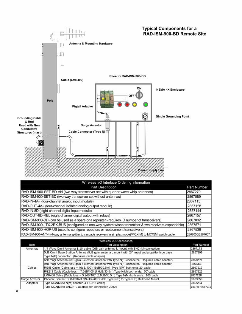
Typical Components for aRAD-ISM-900-BD Remote Site
Antenna & Mounting Hardware
Phoenix RAD-ISM-900-BD
NEMA 4X Enclosure
Surge Arrestor
Pigtail Adapter
Cable (LMR400)
Grounding Cable& Rod
Used with NonConductive
Structures (mast) Cable Connector (Type N)
Single Grounding Point
Item Part Description Part NumberAntennas 1/4 Wave Omni Antenna & 10' cable (0dB gain antenna L mount with BNC (M) connection) 2867173
5dB Omni Base Station Antenna (5dB gain antenna L mount with 24" mast and propeller type base 2867199Type N(F) connector. (Requires cable adapter)6dB Yagi Antenna (6dB gain 3-element antenna with Type N(F) connector. Requires cable adapter) 28672099dB Yagi Antenna (9dB gain 7-element antenna with Type N(F) connector. Requires cable adapter) 2867351
Cables RG58 Cable (Cable loss = 16dB/100' (16dB/30.5m) Type N(M) both ends 20' cable 2867212RG213 Cable (Cable loss = 7.6dB/100' (7.6dB/30.5m) Type N(M) both ends. 50' cable 2867225LMR400 Cable (Cable loss = 3.9dB/100' (3.9dB/30.5m) Type N(M) both ends. 100' cable 2867238
Surge Arrestor Phoenix Contact COAXTRAB CN-UB-280DC-BB Type N(F) to Type N(F) Bulkhead Mount 5603859Adapters Type MCX(M) to N(M) adapter (4' RG316 cable) 2867254
Type MCX(M) to BNC(F) / adapter for connection J0004 2867267/2867241
Wireless I/O Accessories
6
Pole
ON
OFF
Power Supply Line
Part Description Part NumberRAD-ISM-900-SET-BD-AN (two-way transceiver set with quarter-wave whip antennas) 2867270RAD-ISM-900-SET-BD (two-way transceiver set without antennas) 2867089RAD-IN-4A-I (four-channel analog input module) 2867115RAD-OUT-4A-I (four-channel isolated analog output module) 2867128RAD-IN-8D (eight-channel digital input module) 2867144RAD-OUT-8D-REL (eight-channel digital output with relays) 2867157RAD-ISM-900-BD (can be used as a spare or a repeater - requires ID number of transceivers) 2867092RAD-ISM-900-1TX-2RX-BUS (configured as one-way system w/one transmitter & two receivers-expandable) 2867571RAD-ISM-900-HOP-US (used to configure repeaters or replacement transceivers) 2867539RAD-ISM-900-ANT-4 (4-way antenna splitter to cascade receivers in simplex mode)/MCX(M) to MCX(M) patch cable 2867050/2867607
Wireless I/O Interface Ordering Information
Antennas (a brief overview)dBi
The FCC Part 15 regulations limit the antenna system gain for a 1 Watt unlicensed radio system to 6dBi.This is based on an "isotropic" antenna model or "theoretical" antenna that radiates equally well in all directions. Such an antenna does not exist in the real world,but for purposes of determining the amount of antenna system gain permissible under Part 15 of this theoretical model is used.
The importance of understanding "theoretical" antennas versus "real" antennas has to do with the fact that the FCC views antenna gain in terms of dBi while theantenna manufacturers typically rate antenna gain in terms of dBd, which relates to a real world antenna known as a half-wave dipole. This difference in startingpoints influences "the math" a company like Phoenix uses when correctly determining the gain/loss of an antenna, cable and connector system it supplies.
How is "the math" influenced? Without going into a long technical discussion, simply stated, the difference between dBd and dBi is expressed by the value 2.15.An antenna with a gain of 3dBd is viewed by the FCC as having a gain of 3 + 2.15 = 5.15dBi.
Since most end-users seldom use or understand dBd, dBi, or dBm (not discussed here), but instead use the general "catch phrase" dB when referring to the gain/loss of antenna system components, we recommend that they are aware of the fact that Phoenix Contact uses the following standard formula when determiningGain/Loss of an antenna system connected to a 1 Watt Phoenix FHSS radio.
Antenna gain (dB) - cable/connector losses (dB) + 2.15 = System Gain/Loss in dBi (not to exceed 6dBi)
Gain
In simple terms, gain can be thought of as the yardstick for determining how far a radio/cable/antenna system will transmit a signal by "focusing" the radiatedenergy produced by that radio. The simplest antenna - a 0dBi Omni - can be visualized as radiating signals in a sphere. To add "gain" to such an antenna, theradiation pattern of the energy can be shaped/focused, and in the case of an Omni directional antenna one thing that can be done is to flatten, or squish, thesphere. By turning the sphere into a donut, less energy is allowed to radiate vertically and more energy is diverted horizontally. An Omni antenna with its energyfocused in this fashion will radiate energy further on a horizontal plane. Nothing is added to the system - only the radiation pattern is changed.
Loss
Loss is the yardstick, often given in "dB," for measuring the resistance of all the things that reduce the strength of a signal as it travels to the antenna. Cables,connectors, surge protectors, etc. all absorb energy from the signal as it passes through them. LMR400 cable, for example, has a loss of 3.9dB per 100 feet.When calculating antenna gain and cable loss, be sure to add 2.15 to the final value in order to convert the total dB gain/loss to dBi.
Gain/Loss Example
An antenna with 6dB gain will be mounted on a mast and require 100 feet of LMR400 cable. Using the formula given above, this would be calculated as 6dB -3.9dB + 2.15 = 4.25dBi. Since this is within the 6dBi limit, it would be acceptable under FCC Part 15 to implement this system.
Types of Antennas
Omni directional antennas radiate and receive signals in all directions. They usually resemble vertical rods but can come in other shapes as well. Some havehorizontal rods at their base to form a ground plane for increased performance. Because Omni antennas focus their gain over a wide area, they are typicallyused at MASTER radios that need to send and receive information to and from many surrounding radios, and with radio systems separated by short distances orresiding in obstructed locations where the signals are bouncing around structures and buildings.
Yagi antennas are uni-directional, meaning they have their energy focused tightly enough to only transmit and receive signals in the direction they are pointed.Yagi antennas are useful when you want to increase signal strength in one direction and send the signal farther than you could with an Omni antenna. They aretypically used in outdoor installations to cover long distances from point to point.Antenna Height
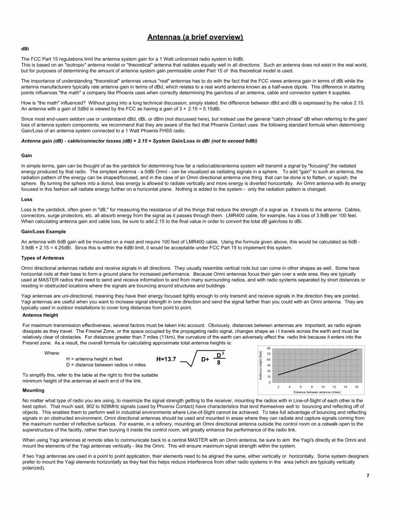
For maximum transmission effectiveness, several factors must be taken into account. Obviously, distances between antennas are important, as radio signalsdissipate as they travel. The Fresnel Zone, or the space occupied by the propagating radio signal, changes shape as i t travels across the earth and must berelatively clear of obstacles. For distances greater than 7 miles (11km), the curvature of the earth can adversely affect the radio link because it enters into theFresnel zone. As a result, the overall formula for calculating approximate total antenna heights is:
Where:H = antenna height in feetD = distance between radios in miles
To simplify this, refer to the table at the right to find the suitableminimum height of the antennas at each end of the link.
H=13.7 D+ 8D 2
0
15
30
45
60
75
90
2 4 6 8 10 12 14 16
Distance between antenna (miles)
Ant
enna
hei
ght (
feet
)
Mounting
No matter what type of radio you are using, to maximize the signal strength getting to the receiver, mounting the radios with in Line-of-Sight of each other is thebest option. That much said, 902 to 928MHz signals (used by Phoenix Contact) have characteristics that lend themselves well to bouncing and reflecting off ofobjects. This enables them to perform well in industrial environments where Line-of-Sight cannot be achieved. To take full advantage of bouncing and reflectingsignals in an obstructed environment, Omni directional antennas should be used and mounted in areas where they can radiate and capture signals coming fromthe maximum number of reflective surfaces. For examle, in a refinery, mounting an Omni directional antenna outside the control room on a catwalk open to thesuperstructure of the facility, rather than burying it inside the control room, will greatly enhance the performance of the radio link.
When using Yagi antennas at remote sites to communicate back to a central MASTER with an Omni antenna, be sure to aim the Yagi's directly at the Omni andmount the elements of the Yagi antennas vertically - like the Omni. This will ensure maximum signal strength within the system.
If two Yagi antennas are used in a point to point application, their elements need to be aligned the same, either vertically or horizontally. Some system designersprefer to mount the Yagi elements horizontally as they feel this helps reduce interference from other radio systems in the area (which are typically verticallypolarized).
7

Specifications
2867092 RAD-ISM-900-BDGeneralRange 600 to 1000 feet (180 to 305m) in-plant [obstructed]; 4-5 miles (6-8km) LOS
with Omni antenna; 20+ miles (32+km) LOS with Yagi antennaInputs One (1) 4-20mA analog input (16-bit, 170 ohms impedance)
Two (2) discrete inputs (5-36VDC)Outputs One (1) 4-20mA analog output (16-bit, short-circuit protected)
Two (2) discrete outputs (dry contact, NO, contact rating: 120VAC/5A)I/O Expansion Capability Four (4) analog and eight (8) discrete I/O modulesRepeatability Current loop: 0.02%Accuracy Current loop: 0.2% of full-scale @ 77°F (25°C)Wiring Connections 12-24 AWG screw-type terminals; removable terminal blocksMounting DIN rail mountPrimary PowerInput Voltage 9 to 30VDCReverse Polarity Protection YesSurge Protection YesPower Consumption 75mA (average) / 200mA (peak) @ 24VDC during transmission (plus I/O modules)TransceiverFrequency 902 to 928MHz - ISM bandTransmit Power 1 Watt (30dBm)RX Sensitivity -105dBmUnit ID Factory configured (unique); 16-bit coding of each transceiver pair allows multiple
units to be used in the same areaAntenna Connector MCX femaleAntenna Impedance 50 ohmsDiagnosticsIndicators External LED�s (Power, RF Link, I/O status)/RF link relay 120 VAC/5 AEnvironmentalHumidity 20% - 90% (non-condensing)Temperature Operating: -40°F to 158°F (-40°C to 70°C)Size 4.5� x 3.9� x 0.9� (114mm x 99mm x 23mm)Weight 5.3 oz (150 g)Enclosure NEMA 1 (equivalent to IP20)Agency ApprovalsFCC Part 15.247ISC RSS 210CSA/C & US Class I Div 2 (Groups A, B, C, D)
2867144 RAD-IN-8D Discrete Input Module � Low VoltChannels Eight (8)Input Voltage Range 5 to 36VAC/DCInput Impedance 5K ohmsOptically Isolated 3kV (input/output and channel/channel)Reverse Polarity Protected YesOver-Voltage Rating 100VAC/DC max.Power Consumption 26mA
2867157 RAD-OUT-8D-REL Discrete Output Module � 8 Ch, RelayChannels Eight (8)Output Terminals Dry contact (NO)Contact Ratings 120VAC/5APower Consumption 10mA @ 24VDC (outputs OFF)
100mA @ 24VDC (outputs ON)2867115 RAD-IN-4A-I 4-20mA Analog Input Module � 4 Ch
Channels Four (4)Resolution 16-bitInput Impedance 170 ohmsReverse Polarity Protected YesOver-Voltage Rating 42VDC max.Accuracy 0.2%Power Consumption 32mA (inputs disconnected)
2867128 RAD-OUT-4A-I 4-20mA Analog Output Module � 4 Ch, ISOLChannels/Load per Channel Four (4)/9 V voltage drop per channelResolution 16-bitShort-Circuit Protection YesOptically Isolated 3kV (input/output and channel/channel)Accuracy 0.12%Power Consumption 32mA (outputs disconnected)
I/O Expansion Modules