wireless charging solutions: deep dive of wireless
TRANSCRIPT

Company Public – NXP, the NXP logo, and NXP secure connections for a smarter world are trademarks of NXP
B.V. All other product or service names are the property of their respective owners. © 2018 NXP B.V.
Technical Director
Security & Connectivity Solutions
Charlie Wu
Wireless Charging Solutions: Deep Dive of Wireless Charging Transmitter
August 2018 | AMF-SMC-T3144
COMPANY PUBLIC 1COMPANY PUBLIC 1
• How Wireless Charging Works
• Power Control and Communications
• Object Detection – Analog Ping
• Foreign Object Detection (FOD)
• NXP Wireless Charging Solution
• Wireless Charging Enablement
Agenda
COMPANY PUBLIC 2
How Wireless Charging Works
COMPANY PUBLIC 3
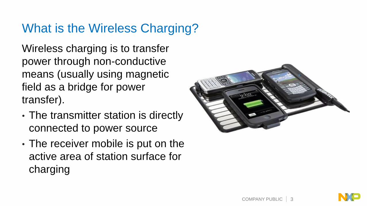
What is the Wireless Charging?
Wireless charging is to transfer
power through non-conductive
means (usually using magnetic
field as a bridge for power
transfer).
• The transmitter station is directly
connected to power source
• The receiver mobile is put on the
active area of station surface for
charging
COMPANY PUBLIC 4
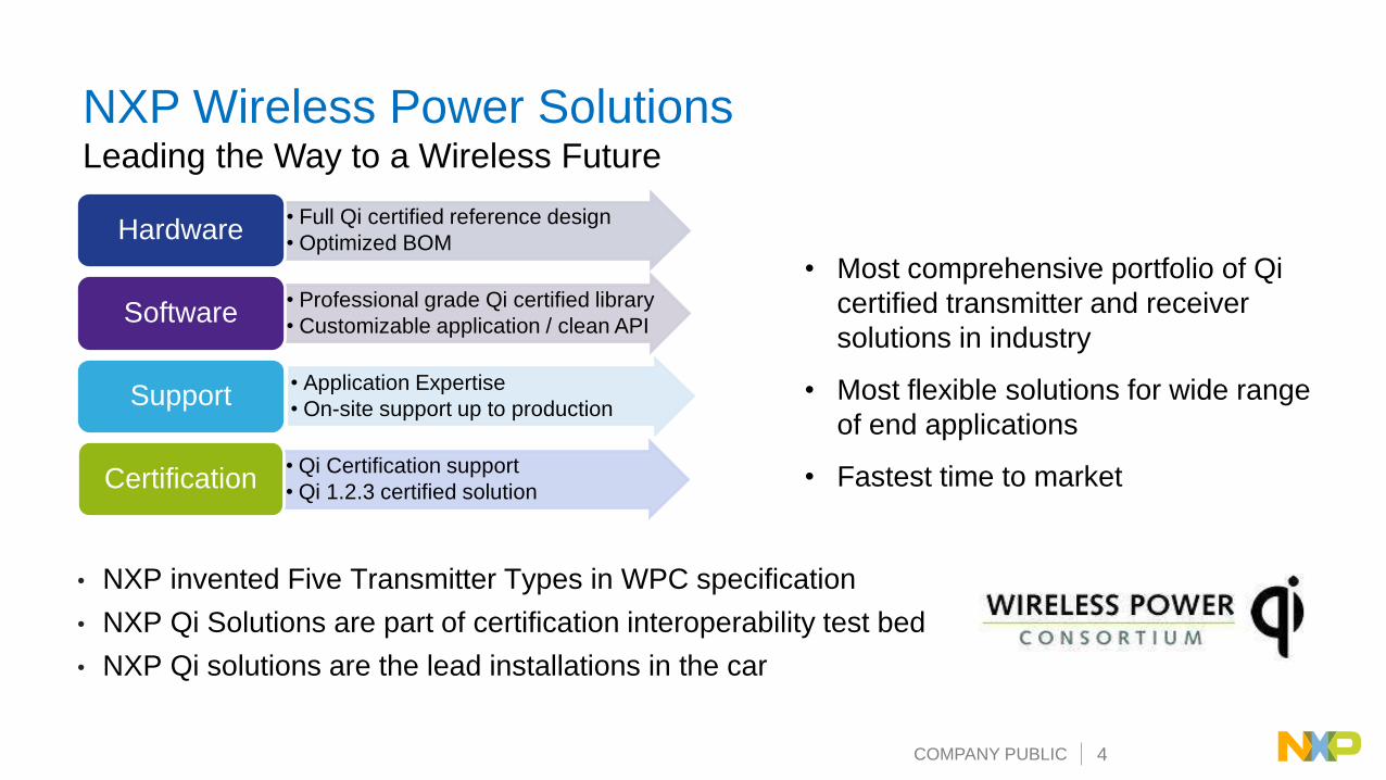
NXP Wireless Power SolutionsLeading the Way to a Wireless Future
• Full Qi certified reference design
• Optimized BOMHardware
• Professional grade Qi certified library
• Customizable application / clean APISoftware
• Application Expertise
• On-site support up to productionSupport
• Qi Certification support
• Qi 1.2.3 certified solutionCertification
• Most comprehensive portfolio of Qi
certified transmitter and receiver
solutions in industry
• Most flexible solutions for wide range
of end applications
• Fastest time to market
• NXP invented Five Transmitter Types in WPC specification
• NXP Qi Solutions are part of certification interoperability test bed
• NXP Qi solutions are the lead installations in the car
COMPANY PUBLIC 5
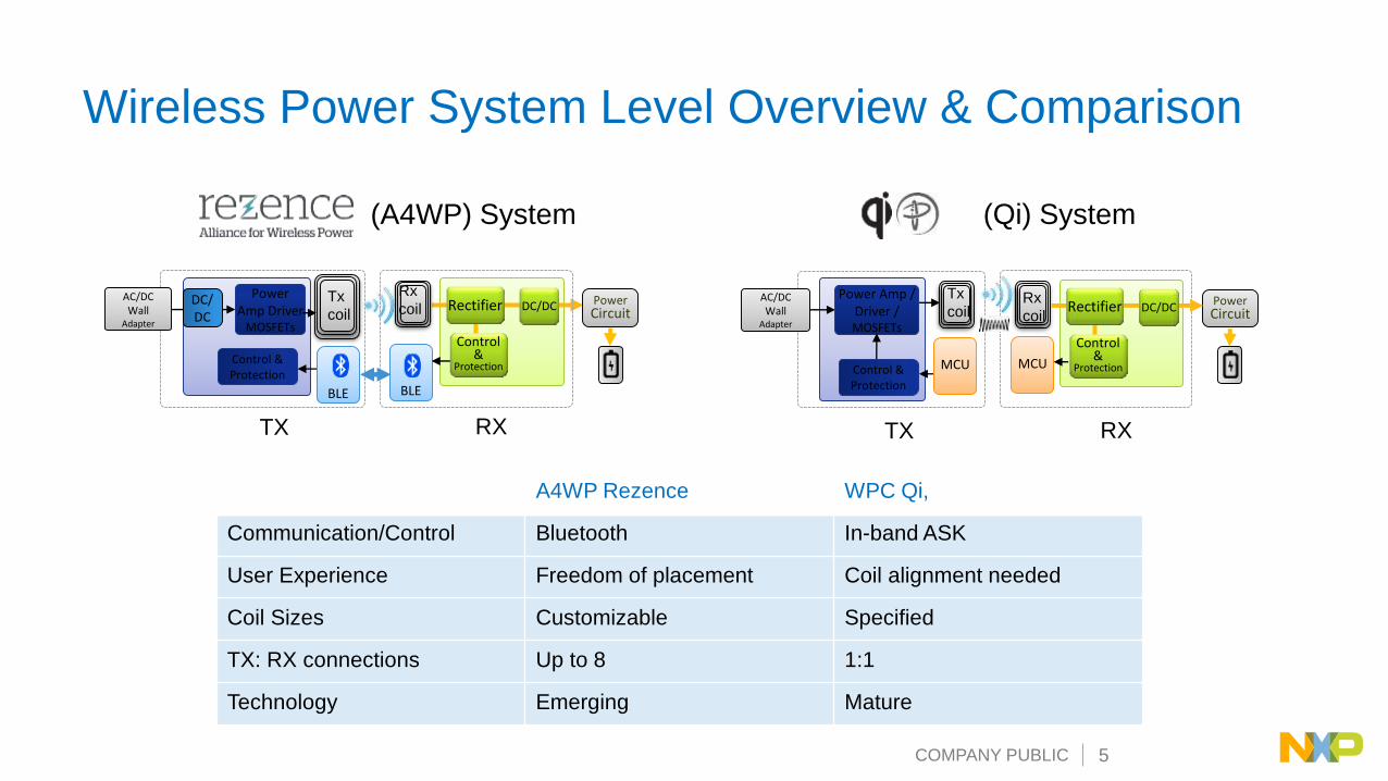
Wireless Power System Level Overview & Comparison
(Qi) System
PowerCircuit
Power Amp /Driver / MOSFETs
Tx
coilRx
coil
AC/DCWall
Adapter
TX RX
Control & ProtectionBLE
TX RX
PowerCircuit
Power Amp Driver
MOSFETs
Tx
coil
Rx
coilAC/DCWall
Adapter
Rectifier DC/DCDC/DC
(A4WP) System
A4WP Rezence WPC Qi,
Communication/Control Bluetooth In-band ASK
User Experience Freedom of placement Coil alignment needed
Coil Sizes Customizable Specified
TX: RX connections Up to 8 1:1
Technology Emerging Mature
Control & Protection
Control&
Protection
Rectifier DC/DC
BLE
Control&
Protection MCUMCU

COMPANY PUBLIC 6
Key Wireless Charging Technologies
• Electromagnetic Basics
− Ampere’s Law: An oscillating electric field produces an oscillating magnetic field
− Faraday’s Law: An oscillating magnetic field produces an oscillating electric field
− It’s easy to implement wireless charging using basic electromagnetic principle
• Two Key Wireless Charging Technologies
− Magnetic Induction (MI): Transmitter coil that creates a magnetic field; receiver coil picks up the magnetic field and generates electric current.
− Magnetic Resonance (MR): Both transmitter and receiver coils operate at approximately same natural frequencies.

COMPANY PUBLIC 7
Magnetic Induction Technology
Transmitter coil that creates a magnetic field; receiver coil picks up the
magnetic field and generates electric current
• Advantages: simple, efficient, safe, power scalable, matured
• Key technology challenges: shield, coil alignment, and good coupling
• Disadvantages: limited x/y/z space, difficult for multiple devices operation
together

COMPANY PUBLIC 8
Magnetic Resonance Technology
Both transmitter and receiver coils operate at approximately same
natural frequencies
• Advantages: spatial free, multiple devices support, efficient
• Key technology challenges: power scalable, environment safety, receiver design
• Disadvantages: open magnetic field radiation, additional communication link
(Bluetooth, Zigbee etc.)

COMPANY PUBLIC 9
How Induction Works
• Main application
− Battery charging, or other suitable loads
− For wide range of mobile devices
▪ Mobile phone, camera, mp3 player, headset, …
• Up to 15W of power delivery in commercial products now
− More power at later versions
• Power transfer via magnetic induction (Resonance Task Force)
− Loosely coupled transformer
− At short distance (less than 30~40mm)
dB/dt
I

COMPANY PUBLIC 10
System Overview
Base Station
• Contains one, or more transmitters
• Transmitter provides power to receiver
Base Station
TransmitterTransmitter
Mobile Device
ReceiverTransmitter
Lo
ad
Syste
m
Power
Control
Mobile Device
• Contains a receiver that provides
power to a load (e.g. a battery)
• Receiver provides control
information to transmitter

COMPANY PUBLIC 11
System Overview (Power Conversion)
• Power Conversion Unit converts electrical power to wireless power signal
• Power Pickup Unit converts wireless power signal to electrical power
Base Station
TransmitterTransmitter
Mobile Device
ReceiverTransmitter
Lo
ad
Syste
m
PowerPower Conversion Power Pick-up
Control

COMPANY PUBLIC 12
System Overview (Control)
• Receiver controls the power to the output load
− To the need of the mobile device (required power)
− To the desired operation point (e.g. output current, voltage)
• Transmitter adapts power transfer
− To the need of the receiver (required power)
− To the desired operation point (e.g. primary coil current)
Base Station
TransmitterTransmitter
Mobile Device
ReceiverTransmitter
Lo
ad
Syste
m
PowerPower Conversion Power Pick-up
ControlControl Control

COMPANY PUBLIC 13
System Overview (Communication)
• Receiver sends/receives messages
− To provide control and device information to the transmitter by load modulation on the power signal
− To receive the device information from the transmitter by de-modulation
• Transmitter receives/sends messages
− To receive control and device information from the receiver by de-modulation
− To provide device information to the receiver by frequency modulation on the power signal
Base Station
TransmitterTransmitter
Mobile Device
ReceiverTransmitter
Load
Syste
m
PowerPower Conversion Power Pick-up
ControlControl CommComm Messages
COMPANY PUBLIC 14
TX Power Conversion
Cp
Lp
+
-
Half Bridge
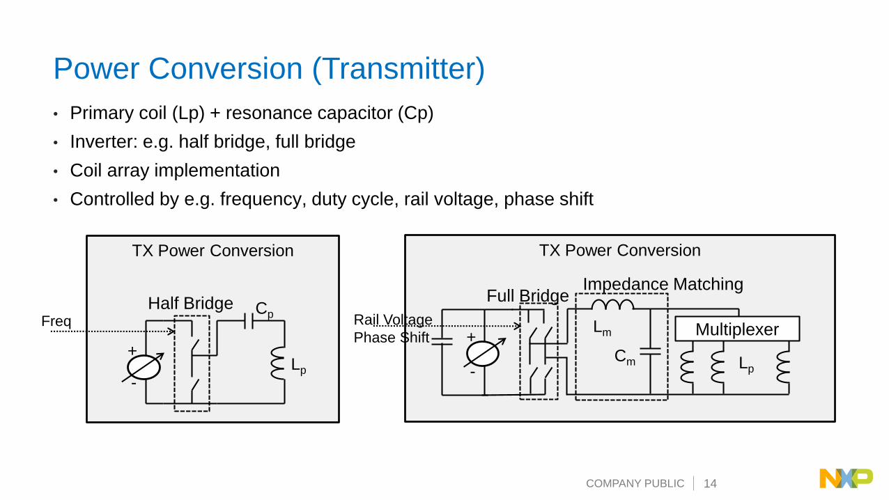
Power Conversion (Transmitter)
• Primary coil (Lp) + resonance capacitor (Cp)
• Inverter: e.g. half bridge, full bridge
• Coil array implementation
• Controlled by e.g. frequency, duty cycle, rail voltage, phase shift
TX Power Conversion
Multiplexer
Lp
+
-
Lm
Cm
Impedance Matching
Freq Rail Voltage
Phase Shift
Full Bridge

COMPANY PUBLIC 15
Power Pickup Unit
Power Pick Up (Receiver)
• Secondary coil (Ls)
• Serial resonance capacitor (Cs) for efficient power transfer (primary resonate freq)
• Parallel resonance capacitor (Cd) for detection purposes (2ndary resonate freq)
• Rectifier: full bridge (diode, or switched) + capacitor
• Output switch for (dis-)connecting the load
Ls
Cs
Cd C
Lo
ad
COMPANY PUBLIC 16
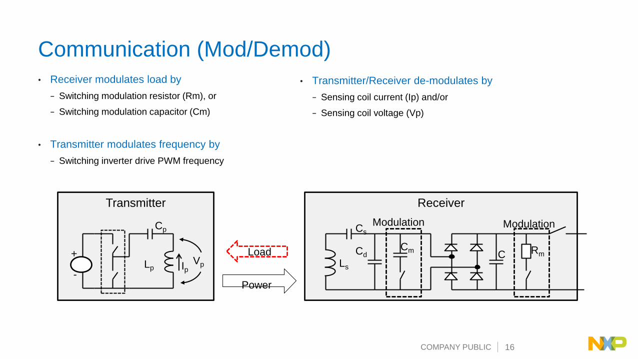
Communication (Mod/Demod)
• Receiver modulates load by
− Switching modulation resistor (Rm), or
− Switching modulation capacitor (Cm)
• Transmitter modulates frequency by
− Switching inverter drive PWM frequency
Transmitter
Cp
Lp
+
-
Receiver
Cd
Ls
Cs
C Rm
ModulationModulation
Cm
IpVp
Load
Power
• Transmitter/Receiver de-modulates by
− Sensing coil current (Ip) and/or
− Sensing coil voltage (Vp)

COMPANY PUBLIC 17
Why Frequency Change Can Change the Output Power?
Gain curves:
• When the main circuit parameters are
determined, circuit gain versus
frequency change under a certain load.
• When Fn > 1, System operates in
inductive load range
• Wnen Fn < 1, System operates in
capacitive load range
• Resonance Frequency calculation
𝐹𝑛 = 1/2𝜋 𝐿𝐶Frequency
Boundary
Inductive
Region
Capacitive
Region
Inductive load range – System stableCapacitive load range – System unstable
COMPANY PUBLIC 18
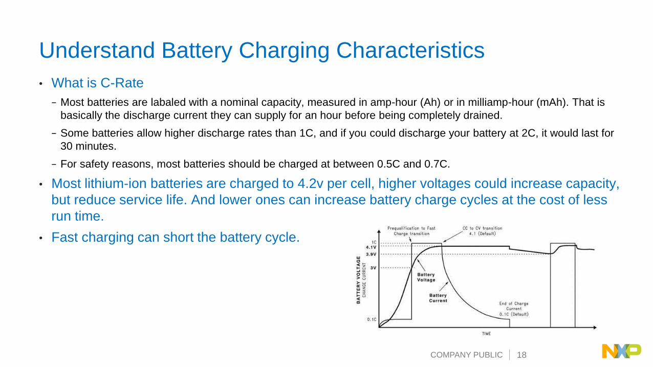
Understand Battery Charging Characteristics
• What is C-Rate
− Most batteries are labaled with a nominal capacity, measured in amp-hour (Ah) or in milliamp-hour (mAh). That is
basically the discharge current they can supply for an hour before being completely drained.
− Some batteries allow higher discharge rates than 1C, and if you could discharge your battery at 2C, it would last for
30 minutes.
− For safety reasons, most batteries should be charged at between 0.5C and 0.7C.
• Most lithium-ion batteries are charged to 4.2v per cell, higher voltages could increase capacity,
but reduce service life. And lower ones can increase battery charge cycles at the cost of less
run time.
• Fast charging can short the battery cycle.
COMPANY PUBLIC 19
Is Charge Speed of Wireless Charging Controlled by
Transmitter?
Answer: Charge speed is controlled by Receiver
The following facts decide the battery charging speed
• Battery temperature affects charge rate and overall charge time
• Phone and charge mat heat dissipation method
• Battery C-rate
• Charging circuit capacity
• Semiconductor device rating

COMPANY PUBLIC 20
Power Control and Communication

COMPANY PUBLIC 21
Communication (Data Format)
• Speed: 2 Kbps
• Bit-encoding: bi-phase
• Byte encoding: Start-bit, 8-bit data, parity-bit, stop-bit
• Packet Structure− Preamble (>= 11bit)
− Header (1 Byte)
▪ Indicates packet type and message length
− Message (1 .. 27 Byte)
▪ One complete message per packet
▪ Payload for control
− Checksum (1 Byte)
1 0 1 0 1 1 0 0
500us
b0 b1 b2 b3 b4 b5 b6 b7
Sta
rt
Sto
p
Pa
rity
Preamble Header Message Checksum

COMPANY PUBLIC 22
Communication & Control • Start
− Transmitter provides signal and senses for presence of an object (potential receiver)
− Receiver waits for signal
• Ping− Receiver indicates presence by communicating
received signal strength
− Transmitter detects response of receiver
• Identification & Configuration− Receiver communicates its identifier and required
power
− Transmitter configures for power transfer contract
• Negotiation− Receiver sends the negotiation request
− Receiver configures for advanced power transfer contract
• Power Transfer− Receiver communicates control data
− Transmitter adapts power transfer
COMPANY PUBLIC 23
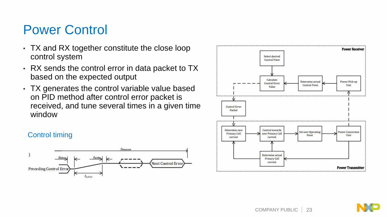
• TX and RX together constitute the close loop control system
• RX sends the control error in data packet to TX based on the expected output
• TX generates the control variable value based on PID method after control error packet is received, and tune several times in a given time window
Power Control
Control timing
COMPANY PUBLIC 24
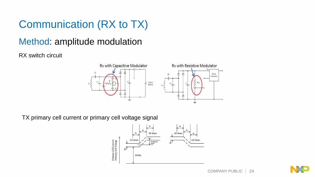
Communication (RX to TX)
Method: amplitude modulation
RX switch circuit
TX primary cell current or primary cell voltage signal

COMPANY PUBLIC 25
Communication Demodulation in wireless charging
TX Coil
Coil
current
signal
WCT1xxxA
ADCDDM
software
module
Benefit Tradeoff
BOM cost reduced Sophisticated demodulation algorithms
PCB area reduced for more compatible applications DSP processing required
Sampling circuit

COMPANY PUBLIC 26
Communication
TXRX
• FSK ( Frequency Shift Keying)
• Speed: fop/512
• Bit-encoding: bi-phase
• Byte-encoding:
− Patten message : 8 bits
− Normal message: Start-bit, 8-bit data, parity-bit,
stop-bit
• Packet structure
− Header (1 Byte) : Indicates packet type and
message length
− Message (1 .. 27 Byte): identification and
configuration information
− Checksum (1 Byte)

COMPANY PUBLIC 27
Communication (TX to RX)
Method: frequency modulation
• Parameters: Polarity, Depth
• Differential bi-phase encoding
COMPANY PUBLIC 28
Object Detection – Analog Ping
COMPANY PUBLIC 29
Object Detect – Analog Ping
• Use 5 PWM pulse, 50% duty cycle, full bridge, same frequency with
digital ping to motivate resonance waveform in TX resonance tank.
• Use ADC to sample resonance waveform.
• ADC is triggered by PWM, ADC samples once for every PWM cycle.
• ADC trigger is delayed a little from start of PWM pulse. For PWM
signal with 50% duty cycle, ADC trigger is delayed 25% PWM period.
• Only the latest ADC sample is used as analog ping sample result.
The latest ADC sample is the ADC sample after PWM pulse stops.
COMPANY PUBLIC 30
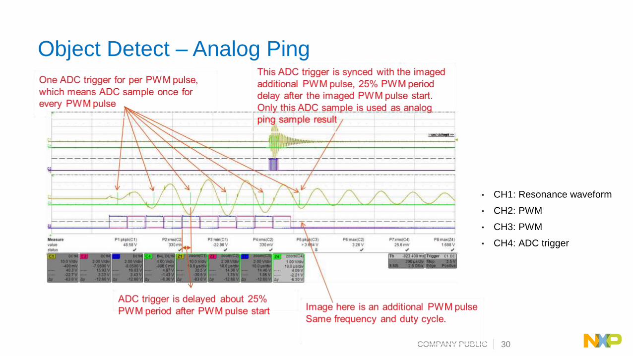
Object Detect – Analog Ping
• CH1: Resonance waveform
• CH2: PWM
• CH3: PWM
• CH4: ADC trigger

COMPANY PUBLIC 31
Foreign Object Detection (FOD)
COMPANY PUBLIC 32
FOD
• For baseline profile power RX:
− FOD based on power loss
• For extended profile power RX:
− Pre-Power transfer FOD based on Q
− FOD during Power transfer based on calibrated power loss

COMPANY PUBLIC 33
Pre-Power Xfer FOD: Q Factor Measurement
• The Q factor is a widespread measure used to characterize resonators. It is defined as the peak energy stored in the circuit divided by the average energy dissipated in it per radian at resonance. Low-Q circuits are therefore damped and lossy and high-Q circuits are underdamped.
• The Q factor of TX coil decreases if FO exits, which could be used to detect FO. RX would send a packet including the reference Q factor for TX to compare and determine if FO exists, as shown in following figure.
• If Q measured is lower than Q threshold, FO is near TX and RX.
• For a series resonant circuit, the Q factor can be calculated as follows:
COMPANY PUBLIC 34
FOD During Power Xfer
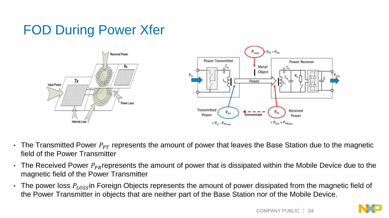
• The Transmitted Power 𝑃𝑃𝑇 represents the amount of power that leaves the Base Station due to the magnetic
field of the Power Transmitter
• The Received Power 𝑃𝑃𝑅represents the amount of power that is dissipated within the Mobile Device due to the
magnetic field of the Power Transmitter
• The power loss 𝑃𝐿𝑂𝑆𝑆in Foreign Objects represents the amount of power dissipated from the magnetic field of
the Power Transmitter in objects that are neither part of the Base Station nor of the Mobile Device.

COMPANY PUBLIC 35
FOD Based on Power Loss for LP RX
For low power RX, the 𝑃𝐿𝑂𝑆𝑆 is calculated as the following formula:
𝑃𝐿𝑂𝑆𝑆 = 𝑃𝑃𝑇-𝑃𝑃𝑅
On Tx side:
𝑃𝑃𝑇 = 𝑃𝐼𝑁 − 𝑃𝑃𝑇𝐿𝑂𝑆𝑆
𝑃𝐼𝑁: the input power of transmitter, could be calculate by input voltage and input
current;
𝑃𝑃𝑇𝐿𝑂𝑆𝑆: the internal loss of transmitter, could be calculated by coil current; the
relationship between 𝑃𝑃𝑇𝐿𝑂𝑆𝑆 and coil current could be described by a quadratic
equation; the coefficients of the equation can be get by calibration through
FreeMASTER GUI.
𝑃𝑃𝑅: the value is sent from Rx through received power packet;

COMPANY PUBLIC 36
FOD Based on Calibrated Power Loss for MP RX
For middle power RX, the 𝑃𝐿𝑂𝑆𝑆 is calculated as the following formula:
𝑃𝐿𝑂𝑆𝑆 = 𝑃𝑃𝑇𝑐𝑎𝑙 − 𝑃𝑃𝑅
𝑃𝑃𝑇𝑐𝑎𝑙 is the calibrated transmitted power, which is used to remove the systematic bias
caused by estimated internal loss of TX and RX. And it can be gotten by the
following fomula:
𝑃𝑃𝑇𝑐𝑎𝑙 = 𝑎 ∗ 𝑃𝑃𝑇 + 𝑏
𝑃𝑃𝑇 = 𝑃𝐼𝑁 − 𝑃𝑃𝑇𝐿𝑂𝑆𝑆
The coefficients “a” and “b” is gotten during online calibration phase, including two
load conditions: a “light” load and a “connected” load.
COMPANY PUBLIC 37
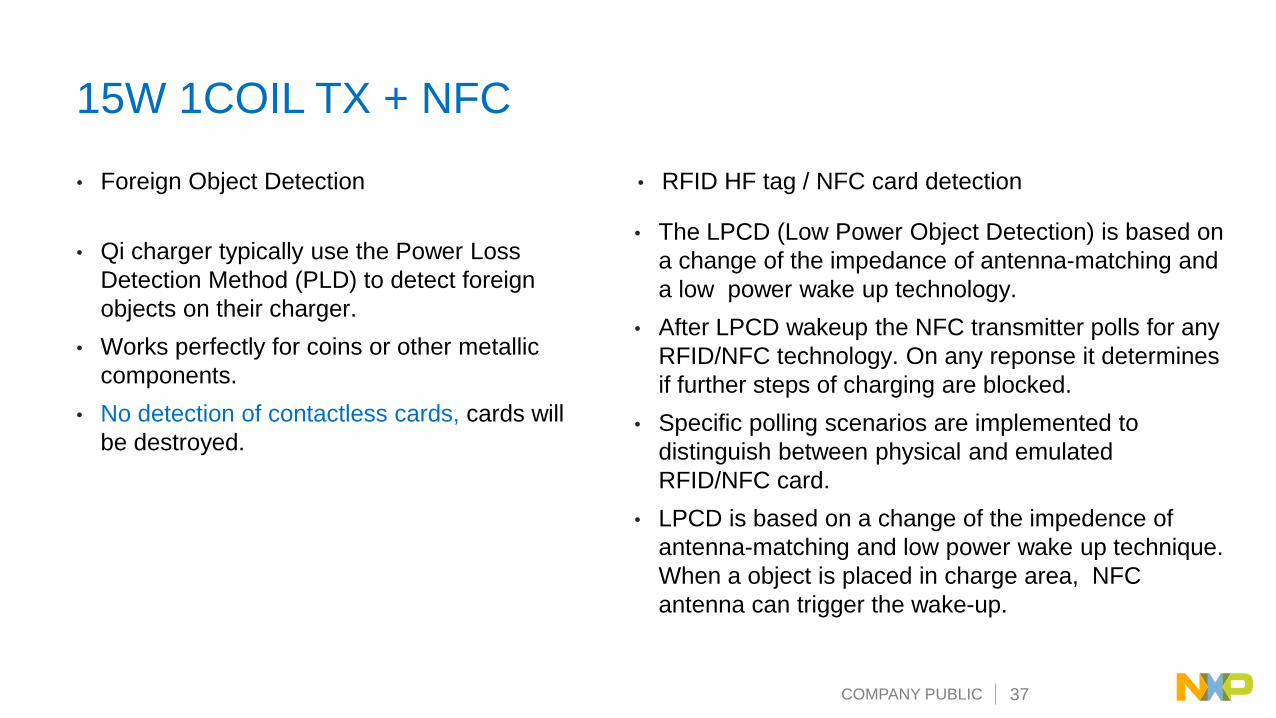
15W 1COIL TX + NFC
• Qi charger typically use the Power Loss
Detection Method (PLD) to detect foreign
objects on their charger.
• Works perfectly for coins or other metallic
components.
• No detection of contactless cards, cards will
be destroyed.
• The LPCD (Low Power Object Detection) is based on
a change of the impedance of antenna-matching and
a low power wake up technology.
• After LPCD wakeup the NFC transmitter polls for any
RFID/NFC technology. On any reponse it determines
if further steps of charging are blocked.
• Specific polling scenarios are implemented to
distinguish between physical and emulated
RFID/NFC card.
• LPCD is based on a change of the impedence of
antenna-matching and low power wake up technique.
When a object is placed in charge area, NFC
antenna can trigger the wake-up.
• Foreign Object Detection • RFID HF tag / NFC card detection

COMPANY PUBLIC 38
15W 1COIL TX + NFC
STARTOPERATION
LPCD
Polling
Contactless
Card
detected
STOPNo NFC
technology
Card Emulation
in phone
detected
STARTCHARGING
Distinguish between
physical and emulated
RFID/NFC card
All RFID technologies such as
ISO/IEC 15693, ISO/IEC 18000-3,
FeliCa and ISO/IEC 14443
tags/cards are detected.
Proprietary technologies may be
added.
COMPANY PUBLIC 39
NXP Wireless Charging solution

COMPANY PUBLIC 40
2kW – 20kW
200W – 2000W
30W – 200W
5 - 15W
<1W
Electric Vehicles
Kitchen Appliances
Laptops, Power Tools,
Home Appliances
Smart Phones
Hearing aids, wearables
Wireless Power is Going Everywhere
NXP delivers easy to implement solutions: fully certified designs, hardware and software, leading controllers, NFC
readers, power devices, application software and libraries with application expertise and support.
Solutions in
the market
today

COMPANY PUBLIC 41
NXP Wireless Charging with Fixed Operating Frequency
Why Fixed Frequency Operating Frequency is needed
• Reduce the emission to wide frequency band
• Avoid the interferences with other wireless control enabled electronics devices
− Such as remote keyless entry; Gate openers.
• Avoid the interference to AM band radio
• Meet the strict regulation in certain countries
COMPANY PUBLIC 42
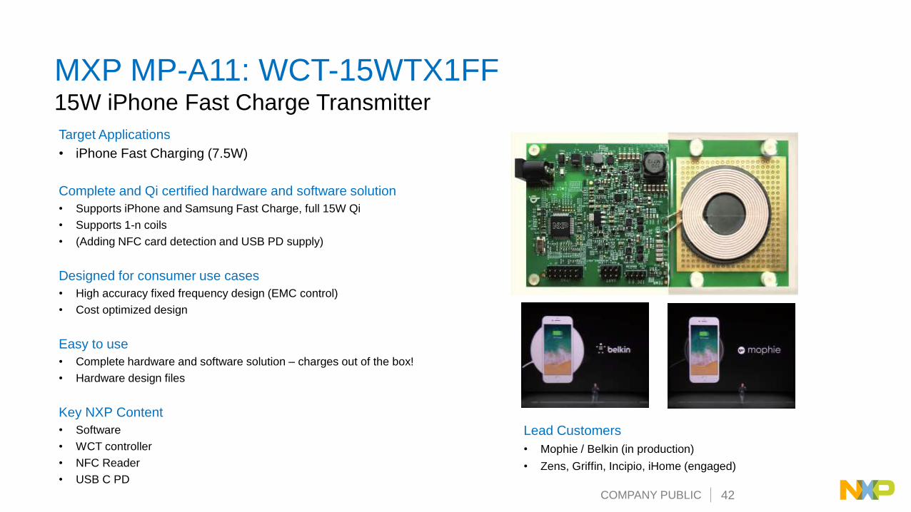
MXP MP-A11: WCT-15WTX1FF15W iPhone Fast Charge Transmitter
Target Applications
• iPhone Fast Charging (7.5W)
Complete and Qi certified hardware and software solution
• Supports iPhone and Samsung Fast Charge, full 15W Qi
• Supports 1-n coils
• (Adding NFC card detection and USB PD supply)
Designed for consumer use cases
• High accuracy fixed frequency design (EMC control)
• Cost optimized design
Easy to use
• Complete hardware and software solution – charges out of the box!
• Hardware design files
Key NXP Content
• Software
• WCT controller
• NFC Reader
• USB C PD
Lead Customers
• Mophie / Belkin (in production)
• Zens, Griffin, Incipio, iHome (engaged)
COMPANY PUBLIC 43
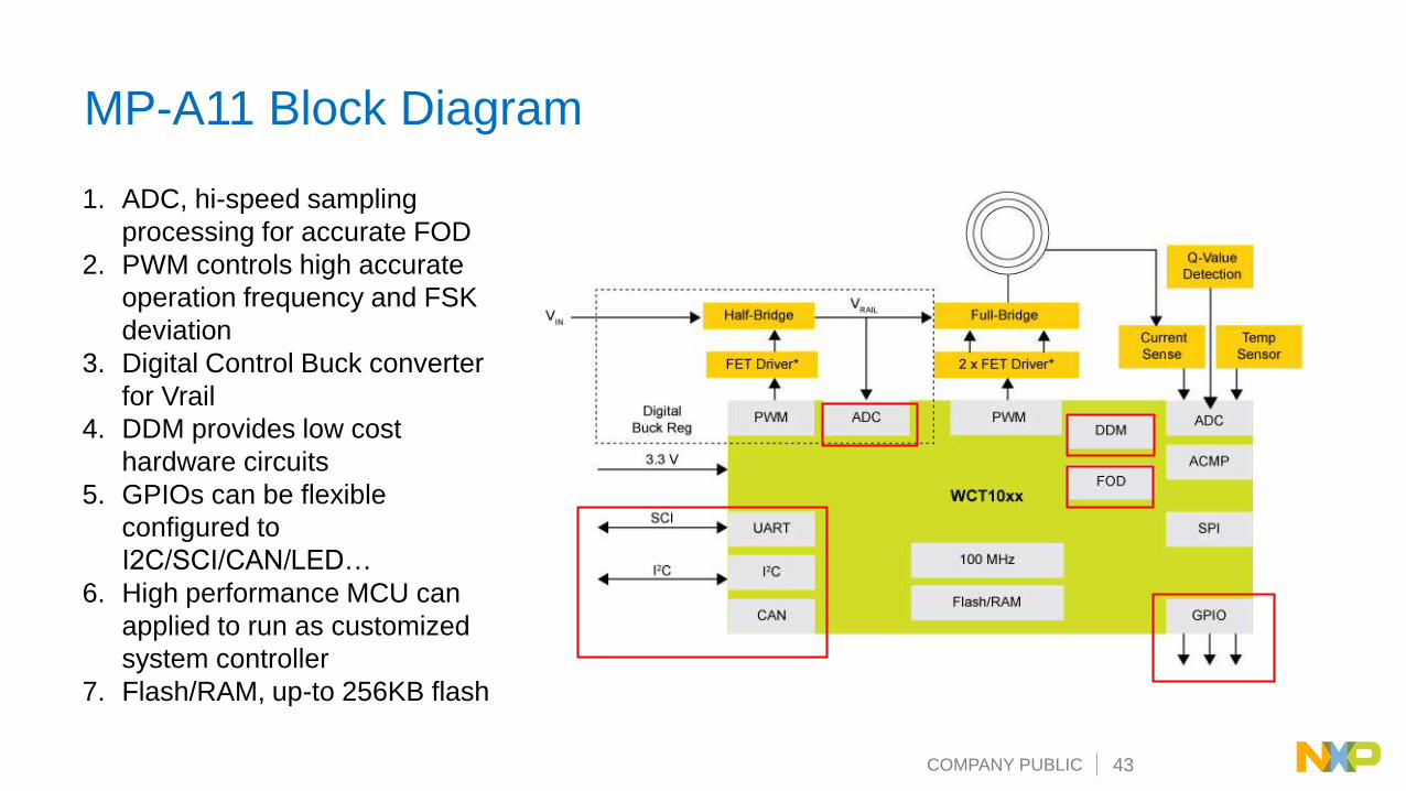
1. ADC, hi-speed sampling
processing for accurate FOD
2. PWM controls high accurate
operation frequency and FSK
deviation
3. Digital Control Buck converter
for Vrail
4. DDM provides low cost
hardware circuits
5. GPIOs can be flexible
configured to
I2C/SCI/CAN/LED…
6. High performance MCU can
applied to run as customized
system controller
7. Flash/RAM, up-to 256KB flash
MP-A11 Block Diagram

COMPANY PUBLIC 44
Target Devices/Platforms:• MWCT1014S
Applications Usage:• 15W automotive multi-coil power TX
Application Features:• Compliant with Wireless Power Consortium (WPC) latest extended power profile
specifications to support up to 15W power transfer
• Support fast charging feature
• Integrated digital demodulation
• Power transfer efficiency exceed 70%
• Support two-way communication, transmitter to receiver by FSK and receiver to
transmitter by ASK
• Rail voltage control strategy
• Low standby power consumption
• Support MP FOD framework – Q factor and power loss FOD methods
• Support any free positioning multi-coil extended power transmitter
• Voltage/current/temperature protection
• Software based solution with Freescale embedded wireless charger software
libraries to provide maximum design freedom and product differentiation
• FreeMASTER GUI tool to enable customization and calibration
• Automotive qualified, AUTOSAR/function safety support
• NFC, CAN-FD enabled
• NXP IP
Availability:• Under development
NXP MP-A9 15W Automotive Power Transmitter
COMPANY PUBLIC 45
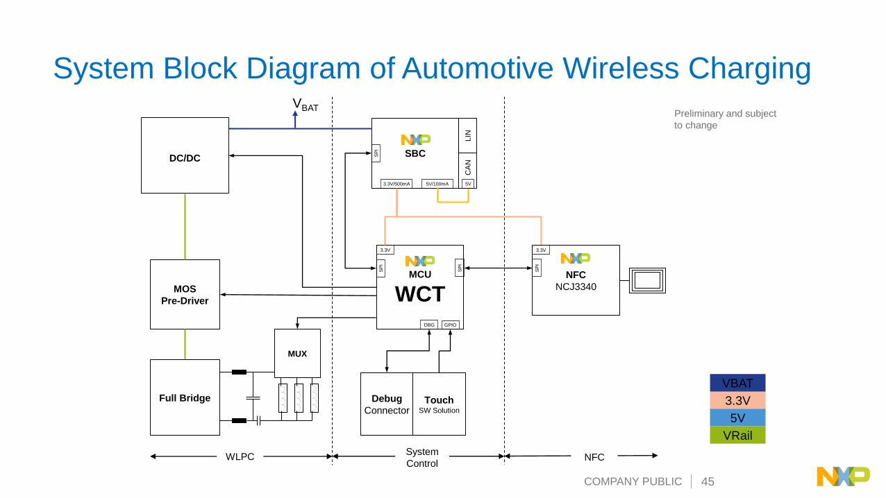
System Block Diagram of Automotive Wireless Charging
TouchSW Solution
Debug
Connector
NFC
NCJ3340
3.3V
SP
I
SBC
LIN
CA
N
5V/100mA3.3V/500mA 5V
SP
I
MCU
WCT
3.3V
SP
I
SP
I
GPIODBG
DC/DC
VBAT
MOS
Pre-Driver
Full Bridge
MUX
3.3V
VBAT
5V
VRail
WLPCSystem
ControlNFC
Preliminary and subject
to change
COMPANY PUBLIC 46
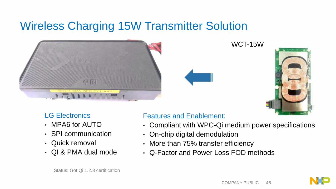
Wireless Charging 15W Transmitter Solution
Features and Enablement:
• Compliant with WPC-Qi medium power specifications
• On-chip digital demodulation
• More than 75% transfer efficiency
• Q-Factor and Power Loss FOD methods
WCT-15W
Status: Got Qi 1.2.3 certification
LG Electronics
• MPA6 for AUTO
• SPI communication
• Quick removal
• QI & PMA dual mode
COMPANY PUBLIC 47
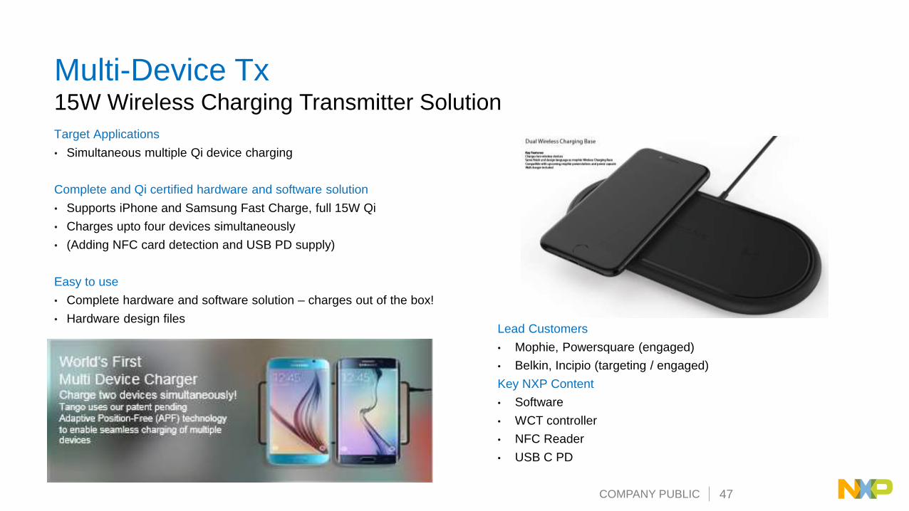
Multi-Device Tx15W Wireless Charging Transmitter Solution
Target Applications
• Simultaneous multiple Qi device charging
Complete and Qi certified hardware and software solution
• Supports iPhone and Samsung Fast Charge, full 15W Qi
• Charges upto four devices simultaneously
• (Adding NFC card detection and USB PD supply)
Easy to use
• Complete hardware and software solution – charges out of the box!
• Hardware design files Lead Customers
• Mophie, Powersquare (engaged)
• Belkin, Incipio (targeting / engaged)
Key NXP Content
• Software
• WCT controller
• NFC Reader
• USB C PD

COMPANY PUBLIC 48
15W Fix-frequency Multi-channel Solution (One to 2 Devices)
• Support two 15W RXs, two
in depended channels can
recognize RXs smartly
• ADC, hi-speed sampling
processing for accurate FOD
• Digital Control Buck
converter for Vrail
• 2 channel DDM provides low
cost hardware circuits
• GPIOs can be flexible
configured to
I2C/SCI/CAN/LED…
• High performance MCU can
applied to run as customized
system controller
COMPANY PUBLIC 49
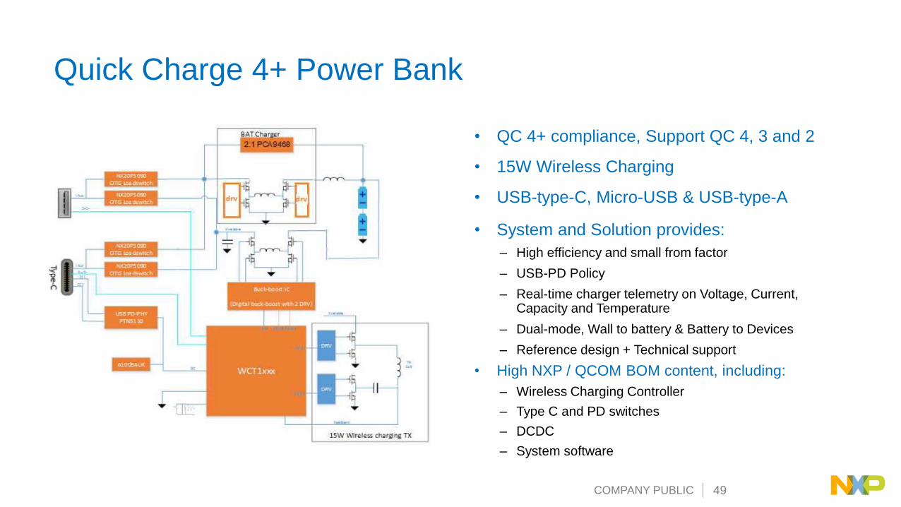
Quick Charge 4+ Power Bank
• QC 4+ compliance, Support QC 4, 3 and 2
• 15W Wireless Charging
• USB-type-C, Micro-USB & USB-type-A
• System and Solution provides:
– High efficiency and small from factor
– USB-PD Policy
– Real-time charger telemetry on Voltage, Current, Capacity and Temperature
– Dual-mode, Wall to battery & Battery to Devices
– Reference design + Technical support
• High NXP / QCOM BOM content, including:
– Wireless Charging Controller
– Type C and PD switches
– DCDC
– System software

COMPANY PUBLIC 50
NXP Wireless Charging Enablement

COMPANY PUBLIC 51
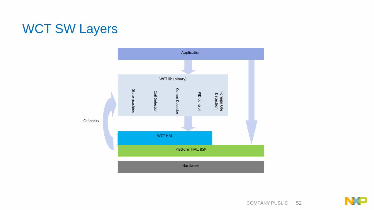
NXP Wireless Charging Controller Portfolio
• The basic kernel functions
of wireless charging is
packed as library form
• The add-on/customized
functions are provided as
API interfaces such as
FOD, Touch sensor, CAN,
NFC, IIC, indicator/buzzer,
etc.
• User is required to write
his/her code for those user
application code
• Sample code projects will
be provided for customer
reference to speed the
development time
COMPANY PUBLIC 52
WCT SW Layers
Application
WCT lib (binary)
WCT HAL
Platform HAL, BSP
Hardware
Callbacks
State mach
ine
Co
mm
Deco
der
PID
con
trol
Foreign
Ob
jD
etection
Co
il Selector

COMPANY PUBLIC 53
AD
C
Fla
sh
Tim
er
PIT
I2C
GP
IO
PW
M
JTA
G
UA
RT
Chip level Library
PID
Co
ntro
l
Fre
q. C
on
trol
Coils Selection
LE
D &
Bu
zzer
Qi
Co
mm
un
icatio
n
FOD
Tou
ch
se
ns
or
Application Level
User Layer•Parameter Calibration & Configuration• User dedicated code
A P I
Power Control Fmaster API
Monitor & Protection&Diagnostic
Object
detection
Processor Layer
Mid Layer
APP Layer
End user Layer
Low power mode
Freemaster
Software Architecture
COMPANY PUBLIC 54
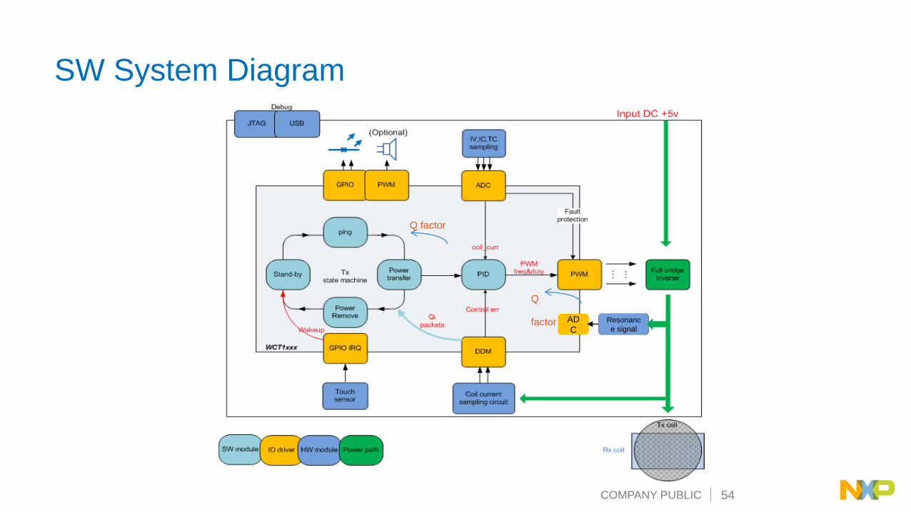
SW System Diagram
Resonanc
e signal
AD
C
Q
factor
Q factor

COMPANY PUBLIC 55
Software Development Tool – CodeWarrior v10.x• Eclipse IDE 3.6.1
• Create a new project in as few as 6 clicks with New Project Wizard
• Retarget a project to a new processor in as few as 6 clicks with MCU Change Wizard
• Build optimized C/C++ code with CodeWarrior HCS08, RS08, DSC, ColdFire, ColdFire+ and Kinetiscompilers
• Troubleshoot and repair embedded applications with CodeWarrior extensions to Eclipse C/C++ Development Tools (CDT)
• Generate initialization and low-level driver code with Processor Expert’s easy-to-use, application design tools and expert knowledge system
• Use trace and profile tools to get emulator-like debug capability with NO additional trace capture hardware for HCS08, V1 ColdFire and Kinetis processors
Accelerate the development of the most complex embedded applications

COMPANY PUBLIC 56
Software Development Tool – GUI
NXP wireless charging GUI tool is based on FreeMASTER, and provides:
• Configuration: System parameters, coil parameters and FOD parameters
• Calibration: Analog signal sensing coefficients, FOD algorithm coefficients
• Debugging: System real-time status and variables

COMPANY PUBLIC 57

NXP, the NXP logo, and NXP secure connections for a smarter world are trademarks of NXP B.V. All other product or service names are the property of their respective owners. © 2018 NXP B.V.
www.nxp.com