wireless automated control system - best buy pool supply llc
TRANSCRIPT

Wireless Automated Control System
1. Introduction1.1 Important Information and Safety Precautions.....................................21.2 FCC Statement.....................................................................................31.3 System Overview..................................................................................41.4 Sol Specifications.................................................................................61.5 Accessories ..........................................................................................8
2. Installation2.1Site Assessment.........................................................................................102.1.1 Plumbing for a Pool and Spa .................................................................122.1.2 Plumbing for a Booster Pump Cleaner...................................................142.1.3 Plumbing for a Solar System..................................................................152.1.4 Plumbing for Water Features .................................................................162.1.5 Equipment Location................................................................................162.2 S-1000 Command Center Installation................................................182.3 S-1020 Command Center Installation................................................202.4 Filter Pump Wiring (1-Speed).............................................................342.5 Filter Pump Wiring (2-Speed).............................................................362.6 Pool Light Wiring ................................................................................382.7 Spa Light Wiring.................................................................................402.8 Fiber Optic Lights Wiring....................................................................422.9 Cleaner Booster Pump Wiring............................................................442.10 Heater Wiring......................................................................................462.11 Other Natural Gas and Propane Gas Heater Wiring..........................502.12 Electric Heater and Heat Pump Wiring...............................................522.13 Solar System Wiring...........................................................................542.14 Blower Wiring......................................................................................562.15 Jet Pump Wiring.................................................................................582.16 Water Feature Pump Wiring...............................................................602.17 Suction Valve Installation....................................................................622.18 Return Valve Installation.....................................................................642.19 Water Feature Valve Installation.........................................................662.20 Suction Cleaner Valve Installation......................................................682.21 Pressure Cleaner Valve Installation....................................................702.22 Actuator Valve Adjustments................................................................722.23 Temperature Sensor Installation.........................................................74
2.23.1 Water Temperature Sensor .....................................................752.23.2 Air Temperature Sensor Installation........................................752.23.3 Solar Temperature Sensor Installation....................................75
2.24 Low Voltage Accessory Wiring ...........................................................762.25 Charger Base Installation...................................................................782.26 Remote Control Battery Installation....................................................802.27 Remote Control Battery Charging ......................................................822.28 Command Center Backup Battery Installation ...................................84
Table of Contents

3. Setup3.1 DIP Switch Settings............................................................................863.2 Turning on the Command Center.......................................................923.3 Remote Control Training.....................................................................963.4 Charging Base Training......................................................................983.5 Antenna Repeater ............................................................................100
4. Operation4.1 Command Center Panel Operation..................................................1024.2 Charger Base Operation...................................................................106
Paging the Remote Control..............................................................1074.3 Remote Control Operation................................................................108
Menu Flowchart ................................................................................1184.4 Safety Delays and Lockouts.............................................................1194.5 Status Messages..............................................................................121
5. Programming5.1 Program Menu..................................................................................1225.2 Clock.................................................................................................1235.3 Auxiliary Labeling .............................................................................1245.4 Schedules.........................................................................................126
Sample Schedules............................................................................1285.5 Options .............................................................................................1305.6 Freeze Protection .............................................................................1325.7 User Modes ......................................................................................134
6. Troubleshooting ............................................................................................138
Warranty ........................................................................................................145
Sol Installation/Operation

1.1 Important Information and Safety Precautions
2 Sol Installation/Operation
I m p o rtant Information and Safety Precautions
1 . READ AND FOLLOW A L L I N S T R U C T I O N S .2. WARNING: Do not allow children to handle this product without close adult supervision.
3. All electrical work must be performed by a licensed electrician and must conform to all national,state and local codes.
4. Do not install or service this equipment if precipitation is present or imminent.
5. Prolonged exposure to water in excess of 100O F will cause hyperthermia. Symptoms caninclude dizziness, fainting, drowsiness, lethargy, and can result in the impairment of judgment.
6. WARNING -- Risk of Electric Shock. Install all electrical equipment at least 5 feet (1.5m) frominside wall of pool or spa using nonmetallic plumbing. Canadian installations must be at leastthree meters from the water.
7. Install at least five feet from the inside wall of the pool and spa. Canadian installations must beat least three meters from the water.
8. A ground-fault circuit interrupter must be provided if this device is used to control underwaterlight fixtures. The conductors on the load side of the ground-fault circuit interrupter shall notoccupy conduits, boxes or enclosures containing other conductors unless the additionalconductors are also protected by a ground-fault circuit interrupter. GFCIs and GFCBs should betested daily before using the pool or spa. Refer to local codes for complete details.
9. A terminal bar marked GROUND is provided within the command center. To reduce the risk ofelectrical shock, connect the terminal bar to the grounding terminal of your electrical service orsupply panel with a continuous green insulated copper wire equivalent in size to the circuitconductors supplying this equipment, but no smaller than 12 AWG (3.3 mm2). In addition, asecond wire connector should be bonded with a minimum 8 AWG (4.115 mm) copper wire toany metal ladders, water pipes, or other metal within 5 feet (1.52 m) of the pool or spa.
10. Always keep the door to the command center closed.
11. The Sol hand-held remote must have a fully charged battery before it is used. Charge thebattery at least 12 hours on the charging base before use or battery will be permanentlydamaged and will need to be replaced (part #12-2038).
11. SAVE THESE INSTRUCTIONS.

FCC Statement
This equipment has been tested and complies with the limits for a Class B digital device, pursuant to Part15 of the FCC rules. These limits are designed to provide reasonable protection against harmfulinterference in a residential installation. This equipment generates, uses and can radiate radio frequencyenergy, and if not installed and used in accordance with the instructions, may cause harmful interferenceto radio communications. However, there is no guarantee that interference will not occur in a particularinstallation. If this equipment does cause harmful interference to radio and television reception, which canbe determined by turning the equipment off and on, the user is encouraged to try to correct theinterference by one or more of the following measures:
• Reorient or relocate the receiving antenna.
• Increase the separation between the equipment and the receiver.
• Connect the equipment into an outlet on a different circuit from the one to which the receiver isconnected.
This equipment has been certified to comply with the limits of a Class B computing device, pursuant to FCCrules. In order to maintain compliance with FCC regulations, shielded cables must be used with thisequipment. Operation with non-approved equipment or unshielded cables is likely to result in interferencewith radio and television reception. The user is cautioned that changes and modifications made to thisequipment without the approval of the manufacturer could void the user’s authority to operate thise q u i p m e n t .
1.2 FCC Statement
Sol Installation/Operation 3
FCC ID: PFU-12-200X
This device complies with Part 15 of the FCC rules. Operation is subject to the following two conditions:
1) This device may not cause harmful interference, and
2) This device must accept any interference received, including interference that may cause undesired operation.
This Class B digital apparatus meets allrequirements of the Canadian Interference-
Causing Equipment Regulations.

1.3 System Overview
4 Sol Installation/Operation
Command Center availablewith or without subpanel

The Polaris Sol 1000 is easy to install in new or existing pools withoutdrilling through walls or patios. The Sol controller receives signals fromthe command center that enables it to activate or deactivate manyfeatures associated with outdoor environments. Step by step menusmake it simple to schedule regular routines such as cleaning or lighting.
The Polaris Sol 1000 complete system includes a streamlined remotecontroller designed for comfortable two-handed operation, a chargingbase, (freestanding or wall mountable), a command center, twomotorized valve actuators and two temperature sensors. The remoteand charging base are designed with no wiring requirements to enableexceptional mobility.
Remote Control features:Lightweight, hand-held remoteWater resistantLarge, easy to read screenEliminates additional wiring for spa-side controlBacklight for operation in low lightPrograms in minutesLong-life rechargeable batteryPaging feature for lost remoteTruly wireless installation
Controls most pool and spa equipmentCirculation pumpTwo-speed pumpsAutomatic pool cleaner pumpsWater feature pumpsSpa blowers and jet pumpsGas and propane heatersSolar heatersElectric lightsFiber optic lightsLow-voltage lights
Controls valves for:Circulation for pool/spa combinationSpa drain, fill and spilloverSolar panelsAutomatic pool cleaners
The Polaris Sol 1000 is a wireless automation system that providesconvenience and flexibility in controlling outdoor equipment throughtimed programming or direct input from the wireless remote. Theseinstructions will detail the installation and wiring of the command center.Detailed programming instructions for the wireless remote are packagedin the remote box.
INTRODUCTION1.3 System Overview
Sol Installation/Operation 5

1.4 Sol Specifications
6 Sol Installation/Operation
S1020Command Centerwithout subpanel4 Standard Relays Included4 Optional Relays
S1000Command Centerwith subpanel4 Standard Relays Included4 Optional Relays

Dimensions:Command Center with Subpanel: 15.5" W x 21.75" H x 4.5"D
Accommodates up to 8 single position or 4 double position circuit breakers
Command Center without Subpanel: 15.5" W x 16.75" H x 4.5" DCharging Base: 10.5" W x 5" H x 2.75" DWireless Remote: 8" W x 5" H x 1.75" D
Specifications:Power Supply: (Input) 50/60 Hz, 120/240 VAC; 1 AMP/0.5 AMP;
Output - 24 VAC, 3 AMP.Contact Rating (high voltage): 25 AMPs, 3 HP @240 VAC,
1.5 HP @ 120 VAC.Contact Rating (low voltage): 8 AMPs @ 120 VAC.
Emergency Service Switches: All circuits.
Command Center Components
• Command Center
• Mounting Brackets
• Circuit Board
• External Antenna
• Antenna O-ring
• Label Set for Custom Auxiliary Identification
• Back-up Battery
• Four high voltage relays
Wireless Remote Components
• Remote
• Charging Base and Table Base
• Two Temperature Sensors
• Two Motorized Valve Actuators
• Installation Guide/Owner’s Manual
• Transformer for Charging Base
• Remote Battery
• Battery Cover
• Battery Cover O-ring
• Screws (to secure battery cover)
• Quick Reference Card
INTRODUCTION1.4 Sol Specifications
Sol Installation/Operation 7

1.5 Accessories
8 Sol Installation/Operation
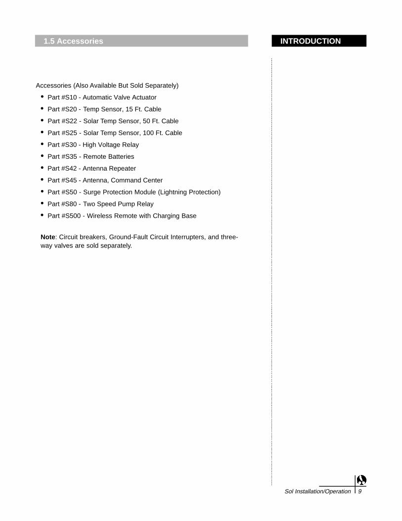
Accessories (Also Available But Sold Separately)
• Part #S10 - Automatic Valve Actuator
• Part #S20 - Temp Sensor, 15 Ft. Cable
• Part #S22 - Solar Temp Sensor, 50 Ft. Cable
• Part #S25 - Solar Temp Sensor, 100 Ft. Cable
• Part #S30 - High Voltage Relay
• Part #S35 - Remote Batteries
• Part #S42 - Antenna Repeater
• Part #S45 - Antenna, Command Center
• Part #S50 - Surge Protection Module (Lightning Protection)
• Part #S80 - Two Speed Pump Relay
• Part #S500 - Wireless Remote with Charging Base
Note: Circuit breakers, Ground-Fault Circuit Interrupters, and three-way valves are sold separately.
INTRODUCTION1.5 Accessories
Sol Installation/Operation 9

2.1 Site Assessment
10 Sol Installation/Operation
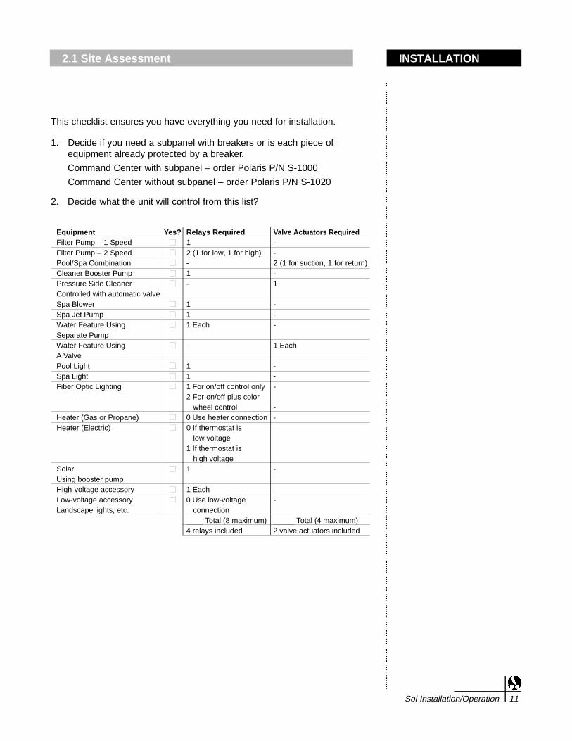
This checklist ensures you have everything you need for installation.
1. Decide if you need a subpanel with breakers or is each piece ofequipment already protected by a breaker.
Command Center with subpanel – order Polaris P/N S-1000
Command Center without subpanel – order Polaris P/N S-1020
2. Decide what the unit will control from this list?
Equipment Yes? Relays Required Valve Actuators RequiredFilter Pump – 1 Speed ■ 1 -Filter Pump – 2 Speed ■ 2 (1 for low, 1 for high) -Pool/Spa Combination ■ - 2 (1 for suction, 1 for return)Cleaner Booster Pump ■ 1 -Pressure Side Cleaner ■ - 1Controlled with automatic valveSpa Blower ■ 1 -Spa Jet Pump ■ 1 -Water Feature Using ■ 1 Each -Separate PumpWater Feature Using ■ - 1 EachA ValvePool Light ■ 1 -Spa Light ■ 1 -Fiber Optic Lighting ■ 1 For on/off control only -
2 For on/off plus color wheel control -
Heater (Gas or Propane) ■ 0 Use heater connection -Heater (Electric) ■ 0 If thermostat is
low voltage1 If thermostat is
high voltageSolar ■ 1 -Using booster pumpHigh-voltage accessory ■ 1 Each -Low-voltage accessory ■ 0 Use low-voltage -Landscape lights, etc. connection
____ Total (8 maximum) _____ Total (4 maximum)4 relays included 2 valve actuators included
INSTALLATION2.1 Site Assessment
Sol Installation/Operation 11

2.1.1 Plumbing for a Pool and Spa
12 Sol Installation/Operation
Plumbing for Non-Booster Pump Pressure-Side Pool Cleaner
Plumbing for a Pool and Spa Combination

Plumbing for a Pool and Spa Combination
• Plumb the pool system in accordance with the standard configuration of apool and spa that share the same filter pump, filter and heater. T h esuction and return actuators will turn at the same time so when the spabutton is selected, the water circulation will switch between the pool ands p a .
• Position the spa at or above the level of the pool. If the spa is attached tothe pool, an overflow dam must be provided between the two bodies ofw a t e r. If the spa is not attached to the pool, an equalizer line that cancarry full pump-flow must be installed between the spa and pool.
• Plumb a check valve on the spa return line if the pool/spa combination hasan elevated spa.
• Plumb a 3-port valve on the suction side of the pool filter pump so thecenter valve port is connected to the filter pump. Connect the spa suctionto one port and the pool suction to the other port.
• Plumb a 3-port valve on the heater output side so the center valve port isconnected downstream of the heater. Connect the spa return to one portand the pool return to the other port.
Plumbing for a Non-Booster Pump Cleaner
• Plumb a 3-port valve on the pool return line after the spa and pool returnvalve. Connect the pool return to one port and the cleaner dedicated lineto the other port.
INSTALLATION2.1.1 Plumbing for a Pool and Spa
Sol Installation/Operation 13
2.1.2 Plumbing for a Booster Pump Cleaner
14 Sol Installation/Operation
Booster Pump Pool Cleaner Plumbing
Solar System Plumbing

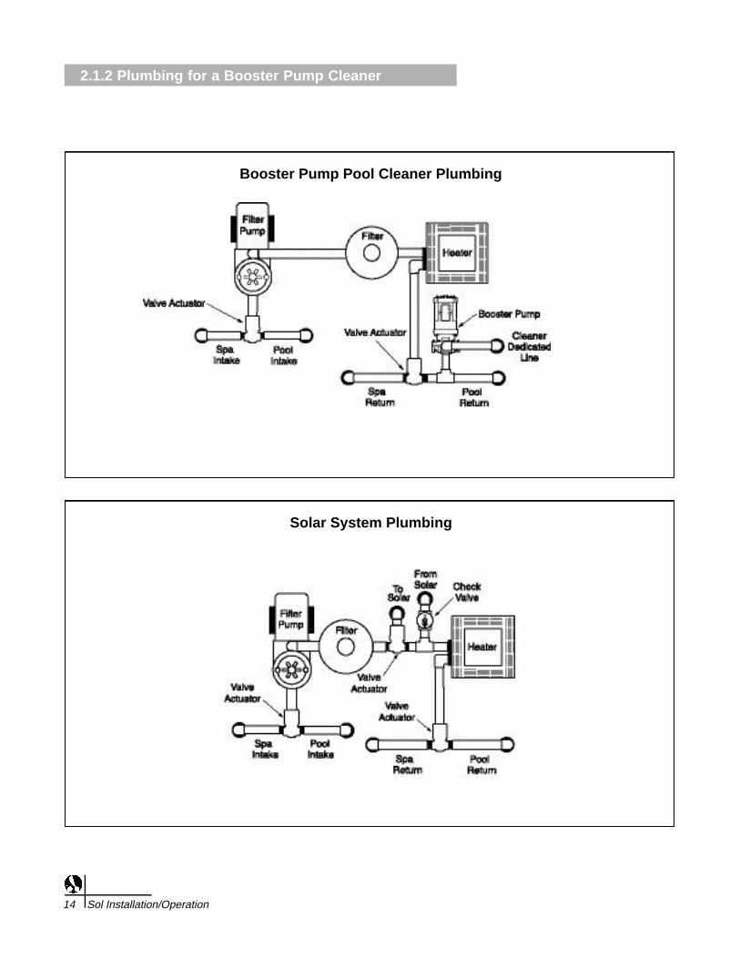
Plumb the booster pump so the suction side is connected downstream ofthe heater and 3-port valve on the pool return side, as near to the groundas possible.
• Plumb the solar feed and return lines before the heater. Install a 3-port solar valve and actuator at the feed line.
• Glazed solar panels require a drain valve to allow draining ofpanels. This prevents damage from overheating water. Install adrain valve at the solar feed line and connect it to the pool fill line.
• A solar temperature sensor (50 ft or 100 ft) will be needed. Thesensor should be mounted on or near the solar panels and connectto the command center with the wire provided. Note: Verify that DIPSwitches 4 and 5 are set to the appropriate settings. See page 89 .
INSTALLATION2.1.2 Plumbing for a Booster Pump Cleaner
2.1.3 Plumbing for a Solar System
Sol Installation/Operation 15

2.1.4 Plumbing for Water Features
16 Sol Installation/Operation

Plumbing for Water Features
• Using a 3-port valve and actuator could eliminate the need for aseparate pump.
• Use a separate pump if the water feature has its own suction supplyand requires a large volume of water.
• If the water feature shares plumbing with other equipment andrequires a booster pump, install a 3-port valve and actuator. SeeSection 2.20 for instructions on how the Sol can automatically openand close the actuator during pool/spa operation.
NOTE: An additional pump can be used if the water feature (e.g.waterfall) is running from a dedicated suction line, and will onlycirculate the pool water to the water feature.
NOTE: A separate booster pump can also be used if additional waterflow is needed. One auxiliary output would be used for the valveactuator and another for the pump. As these two components cannotbe linked, select the water feature you wish to activate prior to turningthe pump on.
INSTALLATION2.1.4 Plumbing for Water Features
Sol Installation/Operation 17

2.2 S-1000 Command Center Installation
18 Sol Installation/Operation
S-1000 Command Center With Sub Panel

IMPORTANT: Do not turn on electrical power until all high voltageand low voltage connections have been made. Failure to follow thisprecaution can result in permanent damage to the commandcenter, transformer or circuit board.
1. Mount the command center with the mounting brackets provided, noless than 5 feet from the pool or spa. It is recommended that theenclosure be mounted so the circuit board (see figure below) isnearly eye level. The radio communication is more reliable with theantenna at a higher position.
Power Supply Ratings: 120/240 VAC up to three conductors plusground, 50/60 Hz.
Note: All electrical equipment must be five feet or more fromthe pool/spa and comply with all national, state and localcodes.
a. If the Polaris command center does not have an electricalsubpanel, install an electrical supply panel with separatebreakers for each load.
b. Ensure that equipment motors have built-in thermal protection.
c. Use the ground bar mounted in the command center forequipment grounding.
d. Bond all equipment, including the command center, if necessary,to a solid ground connection.
e. CAUTION: Adequate drainage must be provided if the poolequipment is to be installed in a pit.
f. In areas where lightning strikes are common, install an externalsurge suppression device (part number 5-50 availableseparately) for both high and low voltage lines.
g. If this enclosure is used for direct connection of underwater lights,a Ground Fault Circuit Breaker (GFCB) or Ground Fault CircuitInterrupter (GFCI) must be used. A rectangular knockout on theside of the enclosure may be used to mount an A P P ROV E Dwiring device for this purpose. If the unit is being installedoutdoors, then an A P P ROV E D rain cover must be installed overthe wiring device in the side knockout. Refer to NEC 680-21 (b) orCEC 687-060, 062, and 066 for further details.
h. Each command center enclosure comes standard with four highvoltage relays. If additional relays are required based on thespecific installation, then they must be purchased separately(part number S-30). Additional relays are installed below thefactory installed relays. Simply remove two mounting screws inthe location where the new relay will be installed, position therelay and secure using the screws just removed.
INSTALLATION2.2 S-1000 Command Center Installation
Sol Installation/Operation 19

2.2 S-1000 Command Center Installation
20 Sol Installation/Operation
1. A wire connector is provided on this unit to connect a minimum No.8 AWG (8.4 mm2) solid copper conductor between this unit and anymetal equipment, metal enclosures of electrical equipment, metalwater pipe, or conduit within 5 feet (1.5m) of the unit.
Feeder wires shall be No. 14 to No. 3 AWG copper rated for 750F or better.
2. Open the command center door. Remove the panel screws and the access panel to gain access to the electrical components. Run the conduit or wire from the power supply panel to the command center.
Note: The number of pieces of equipment to be controlled will dictate the size of conduit needed.
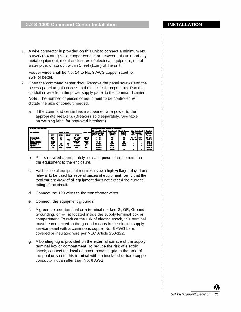
a. If the command center has a subpanel, wire power to the appropriate breakers. (Breakers sold separately. See table on warning label for approved breakers).
b. Pull wire sized appropriately for each piece of equipment fromthe equipment to the enclosure.
c . Each piece of equipment requires its own high voltage relay. If onerelay is to be used for several pieces of equipment, verify that thetotal current draw of all equipment does not exceed the currentrating of the circuit.
d. Connect the 120 wires to the transformer wires.
e. Connect the equipment grounds.
f. A green colored terminal or a terminal marked G, GR, Ground,Grounding, or is located inside the supply terminal box orcompartment. To reduce the risk of electric shock, this terminalmust be connected to the ground means in the electric supplyservice panel with a continuous copper No. 8 AWG bare,covered or insulated wire per NEC Article 250-122.
g. A bonding lug is provided on the external surface of the supplyterminal box or compartment. To reduce the risk of electricshock, connect the local common bonding grid in the area ofthe pool or spa to this terminal with an insulated or bare copperconductor not smaller than No. 6 AWG.
INSTALLATION2.2 S-1000 Command Center Installation
Sol Installation/Operation 21

2.2 S-1000 Command Center Installation
22 Sol Installation/Operation
h. All field-installed metal components such as rails, ladders,drains, or other similar hardware located within 3m of the poolor spa must be bonded together and to the equipment bondinglug with copper conductors not smaller than No. 6 AWG.
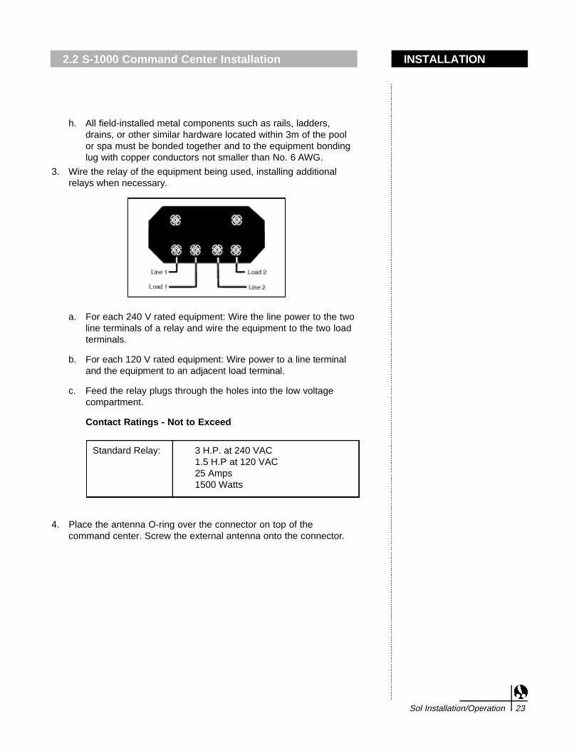
3. Wire the relay of the equipment being used, installing additional relays when necessary.
a. For each 240 V rated equipment: Wire the line power to the twoline terminals of a relay and wire the equipment to the two loadterminals.
b . For each 120 V rated equipment: Wire power to a line terminaland the equipment to an adjacent load terminal.
c. Feed the relay plugs through the holes into the low voltagecompartment.
Contact Ratings - Not to Exceed
4. Place the antenna O-ring over the connector on top of thecommand center. Screw the external antenna onto the connector.
INSTALLATION2.2 S-1000 Command Center Installation
Sol Installation/Operation 23
Standard Relay: 3 H.P. at 240 VAC1.5 H.P at 120 VAC25 Amps1500 Watts

2.2 S-1000 Command Center Installation
24 Sol Installation/Operation

Command Center Circuit Board Installation
1. Unpack the circuit board from its packaging.
2. Remove and retain the two screws from the mounting bracketslocated at the top of the command center. They will be used tosecure the circuit board when all of the electrical connections arec o m p l e t e .
3. Position the circuit board in the command center by aligning thebottom notches of the circuit board with the horizontal divider in thecommand center. The circuit board can remain in this position whilethe connections are being made.
4. Plug in connector.
INSTALLATION2.2 S-1000 Command Center Installation
Sol Installation/Operation 25

2.3 S-1020 Command Center Installation
26 Sol Installation/Operation
S-1020 Command Center Without Sub Panel
IMPORTANT: Do not turn on electrical power until all high voltageand low voltage connections have been made. Failure to follow thisprecaution can result in permanent damage to the commandcenter, transformer or circuit board.
1. Mount the command center with the mounting brackets provided, noless than 5 feet from the pool or spa. It is recommended that theenclosure be mounted so the circuit board (see figure below) isnearly eye level. The radio communication is more reliable with theantenna at a higher position.
Power Supply Ratings: 120/240 VAC up to three conductors plusground, 50/60 Hz.
Note: All electrical equipment must be five feet or more fromthe pool/spa and comply with all national, state and localcodes.
a. If the Polaris command center does not have an electricalsubpanel, install an electrical supply panel with separatebreakers for each load.
b. Ensure that equipment motors have built-in thermal protection.
c. Use the ground bar mounted in the command center forequipment grounding.
d. Bond all equipment, including the command center, if necessary,to a solid ground connection.
e. CAUTION: Adequate drainage must be provided if theequipment is to be installed in a pit.
f. In areas where lightning strikes are common, install an externalsurge suppression device (part number 5-50 availableseparately) for both high and low voltage lines.
g. If this enclosure is used for direct connection of underwater lights,a Ground Fault Circuit Breaker (GFCB) or Ground Fault CircuitInterrupter (GFCI) must be used. A rectangular knockout on theside of the enclosure may be used to mount an A P P ROV E Dwiring device for this purpose. If the unit is being installedoutdoors, then an A P P ROV E D rain cover must be installed overthe wiring device in the side knockout. Refer to NEC 680-21 (b) orCEC 687-060, 062, and 066 for further details.
h. Each command center enclosure comes standard with four highvoltage relays. If additional relays are required based on thespecific installation, then they must be purchased separately(part number S-30). Additional relays are installed below thefactory installed relays. Simply remove two mounting screws inthe location where the new relay will be installed, position therelay and secure using the screws just removed.
INSTALLATION2.3 S-1020 Command Center Installation
Sol Installation/Operation 27

2.3 S-1020 Command Center Installation
28 Sol Installation/Operation

1. A wire connector is provided on this unit to connect a minimum No.8 AWG (8.4 mm2) solid copper conductor between this unit and anymetal equipment, metal enclosures of electrical equipment, metalwater pipe, or conduit within 5 feet (1.5m) of the unit.
Feeder wires shall be No. 14 to No. 3 AWG copper rated for 750F or better.
2. Open the command center door. Remove the panel screws and the access panel to gain access to the electrical components. Run the conduit or wire from the power supply panel to the command center.
Note: The number of pieces of equipment to be controlled will dictate the size of conduit needed.
a. If the command center has a subpanel, wire power to the appropriate breakers. (Breakers sold separately. See table on warning label for approved breakers).
b. Pull wire sized appropriately for each piece of equipment fromthe equipment to the enclosure.
c . Each piece of equipment requires its own high voltage relay. If onerelay is to be used for several pieces of equipment, verify that thetotal current draw of all equipment does not exceed the currentrating of the circuit.
d. Connect the 120V wires to the transformer wires.
e. Connect the equipment grounds.
f. A green colored terminal or a terminal marked G, GR, Ground,Grounding, or is located inside the supply terminal box orcompartment. To reduce the risk of electric shock, this terminalmust be connected to the ground means in the electric supplyservice panel with a continuous copper No. 8 AWG bare,covered or insulated wire per NEC Article 250-122.
g. A bonding lug is provided on the external surface of the supplyterminal box or compartment. To reduce the risk of electricshock, connect the local common bonding grid in the area ofthe pool or spa to this terminal with an insulated or bare copperconductor not smaller than No. 6 AWG.
INSTALLATION2.3 S-1020 Command Center Installation
Sol Installation/Operation 29

2.3 S-1020 Command Center Installation
30 Sol Installation/Operation
h. All field-installed metal components such as rails, ladders,drains, or other similar hardware located within 3m of the poolor spa must be bonded together and to the equipment bondinglug with copper conductors not smaller than No. 6 AWG.
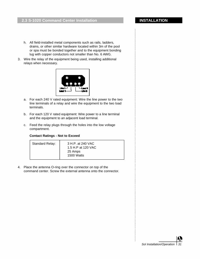
3. Wire the relay of the equipment being used, installing additional relays when necessary.
a. For each 240 V rated equipment: Wire the line power to the twoline terminals of a relay and wire the equipment to the two loadterminals.
b . For each 120 V rated equipment: Wire power to a line terminaland the equipment to an adjacent load terminal.
c. Feed the relay plugs through the holes into the low voltagecompartment.
Contact Ratings - Not to Exceed
4. Place the antenna O-ring over the connector on top of thecommand center. Screw the external antenna onto the connector.
INSTALLATION2.3 S-1020 Command Center Installation
Sol Installation/Operation 31
Standard Relay: 3 H.P. at 240 VAC1.5 H.P at 120 VAC25 Amps1500 Watts
2.3 S-1020 Command Center Installation
32 Sol Installation/Operation

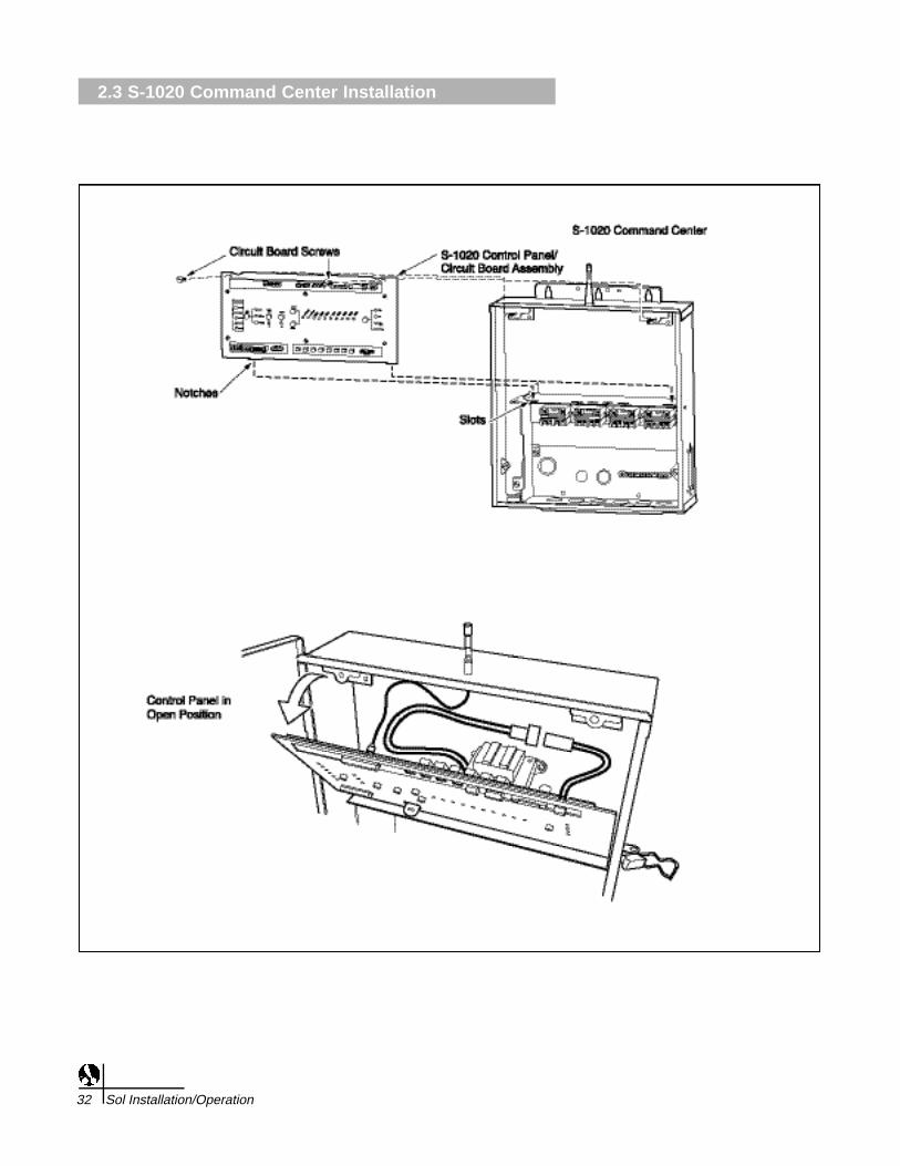
Command Center Circuit Board Installation
1. Unpack the circuit board from its packaging.
2. Remove and retain the two screws from the mounting bracketslocated at the top of the command center. They will be used tosecure the circuit board when all of the electrical connections arec o m p l e t e .
3. Position the circuit board in the command center by aligning thebottom notches of the circuit board with the horizontal divider in thecommand center. The circuit board can remain in this position whilethe connections are being made.
4. Plug in connector.
INSTALLATION2.3 S-1020 Command Center Installation
Sol Installation/Operation 33

2.4 Filter Pump Wiring (1-Speed)
34 Sol Installation/Operation

1. Ensure that equipment motors have built-in thermal protection.
2. Pull wire sized appropriately for each piece of equipment from theequipment to the enclosure.
3 . Each piece of equipment should have its own high voltage relay. Insome cases, a relay may be shared by more than one piece ofequipment as long as total amperage draw does not exceed 25 A m p s91500 watts).
4. Connect the equipment grounds.
5. A green colored terminal or a terminal marked G, GR, Ground,Grounding, or is located inside the supply terminal box orcompartment. To reduce the risk of electric shock, this terminal mustbe connected to the ground means in the electric supply servicepanel with a continuous copper No. 8 AWG bare, covered orinsulated wire per NEC Article 250-122.
6. A bonding lug is provided on the external surface of the supplyterminal box or compartment. To reduce the risk of electric shock,connect the local common bonding grid in the area of the pool orspa to this terminal with an insulated or bare copper conductor notsmaller than No. 8 AWG.
7. Wire the relay of the equipment being used, installing additional relays when necessary.
8. For each 240 V rated equipment: Wire the line power to the two lineterminals of a relay and wire the equipment to the two loadterminals.
9 . For each 120 V rated equipment: Wire power to a line terminal andthe equipment to an adjacent load terminal.
10. Feed the relay plugs through the holes into the low voltagecompartment.
Contact Ratings - Not to Exceed
INTRODUCTION2.4 Filter Pump Wiring (1-Speed)
Sol Installation/Operation 35
Standard Relay: 3 H.P. at 240 VAC1.5 H.P at 120 VAC25 Amps1500 Watts
IMPORTANT: Do not turnon electrical power untilall high voltage and lowvoltage connections havebeen made. Failure tofollow this precaution canresult in permanentdamage to the commandcenter, transformer orcircuit board.Note: All electricalequipment must be fivefeet or more from thepool/spa and comply withall national, state and localcodes.
2.5 Filter Pump Wiring (2-Speed)
36 Sol Installation/Operation
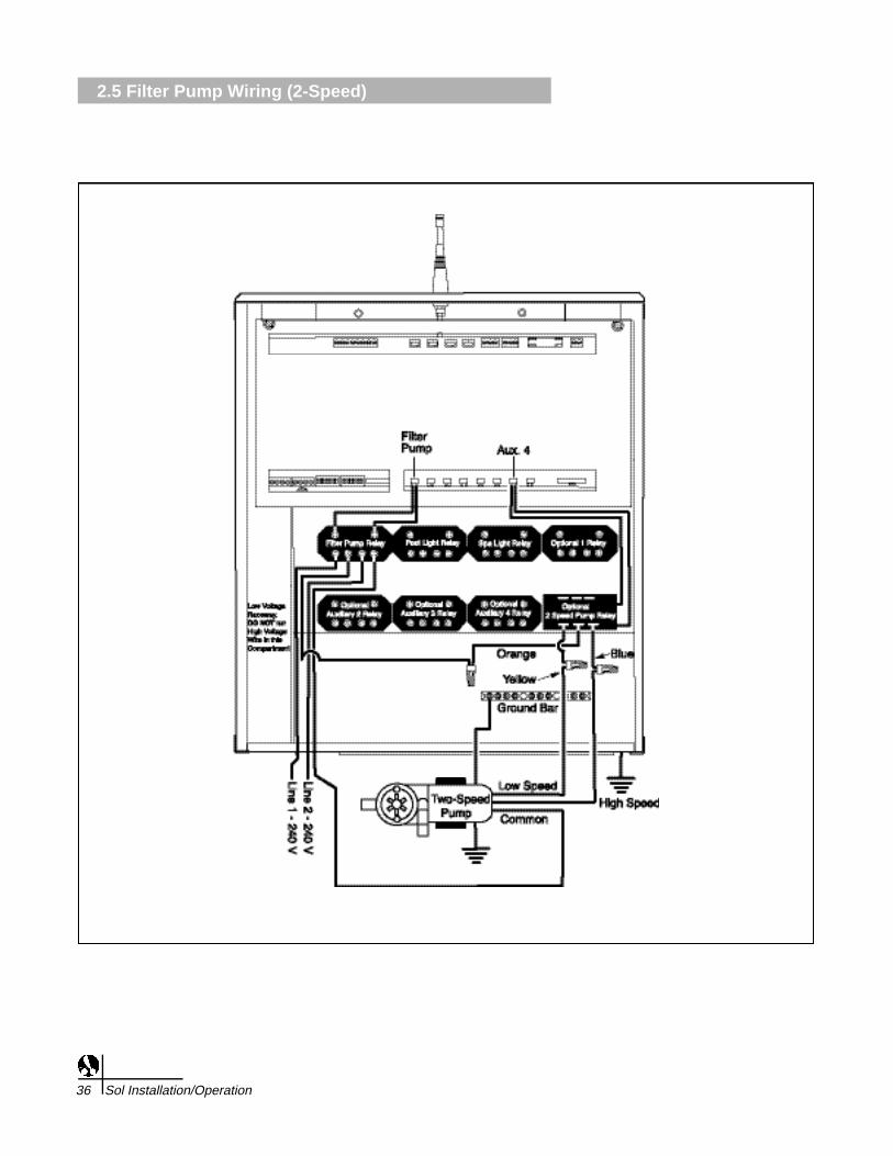
2-Speed Pump
a. To connect a two speed pump, a two speed relay kit (part number S-80) must be purchased. The relay can be mounted in
one of the open positions in the bottom row.
b. See Two Speed Pump Wiring Diagram for system connections.
Contact Ratings - Not to Exceed
Motor wires S-80 2-Speed Relay Wires
Low Speed Wire Blue WireHigh Speed Wire Yellow WireCommon Wire > To one LOAD Orange Wire > To other LOADside of Filter Pump Relay side of Filter Pump Relay
INSTALLATION2.5 Filter Pump Wiring (2-Speed)
Sol Installation/Operation 37
Two Speed 2.5 H.P. at 240 VAC Pump Relay: 1 H.P at 120 VAC
20 Amps

2.6 Pool Light Wiring
38 Sol Installation/Operation

Pool Light Wiring
1. Ensure that equipment motors have built-in thermal protection.
2. Pull wire sized appropriately for each piece of equipment from theequipment to the enclosure.
3 . Each piece of equipment should have its own high voltage relay. Insome cases, a relay may be shared by more than one piece ofequipment as long as total amperage draw does not exceed 25 A m p s91500 watts).
4. Connect the equipment grounds.
5. A green colored terminal or a terminal marked G, GR, Ground,Grounding, or is located inside the supply terminal box orcompartment. To reduce the risk of electric shock, this terminal mustbe connected to the ground means in the electric supply servicepanel with a continuous copper No. 8 AWG bare, covered orinsulated wire per NEC Article 250-122.
6. A bonding lug is provided on the external surface of the supplyterminal box or compartment. To reduce the risk of electric shock,connect the local common bonding grid in the area of the pool orspa to this terminal with an insulated or bare copper conductor notsmaller than No. 8 AWG.
7. Wire the relay of the equipment being used, installing additional relays when necessary.
8. For each 240 V rated equipment: Wire the line power to the two lineterminals of a relay and wire the equipment to the two loadterminals.
9 . For each 120 V rated equipment: Wire power to a line terminal andthe equipment to an adjacent load terminal.
10. Feed the relay plugs through the holes into the low voltagecompartment.
Contact Ratings - Not to Exceed
INSTALLATION2.6 Pool Light Wiring
Sol Installation/Operation 39
IMPORTANT: Do not turnon electrical power until allhigh voltage and lowvoltage connections havebeen made. Failure tofollow this precaution canresult in permanentdamage to the commandcenter, transformer orcircuit board.Note: All electricalequipment must be fivefeet or more from thepool/spa and comply withall national, state and localcodes.
Standard Relay: 3 H.P. at 240 VAC1.5 H.P at 120 VAC25 Amps1500 Watts
2.7 Spa Light Wiring
40 Sol Installation/Operation

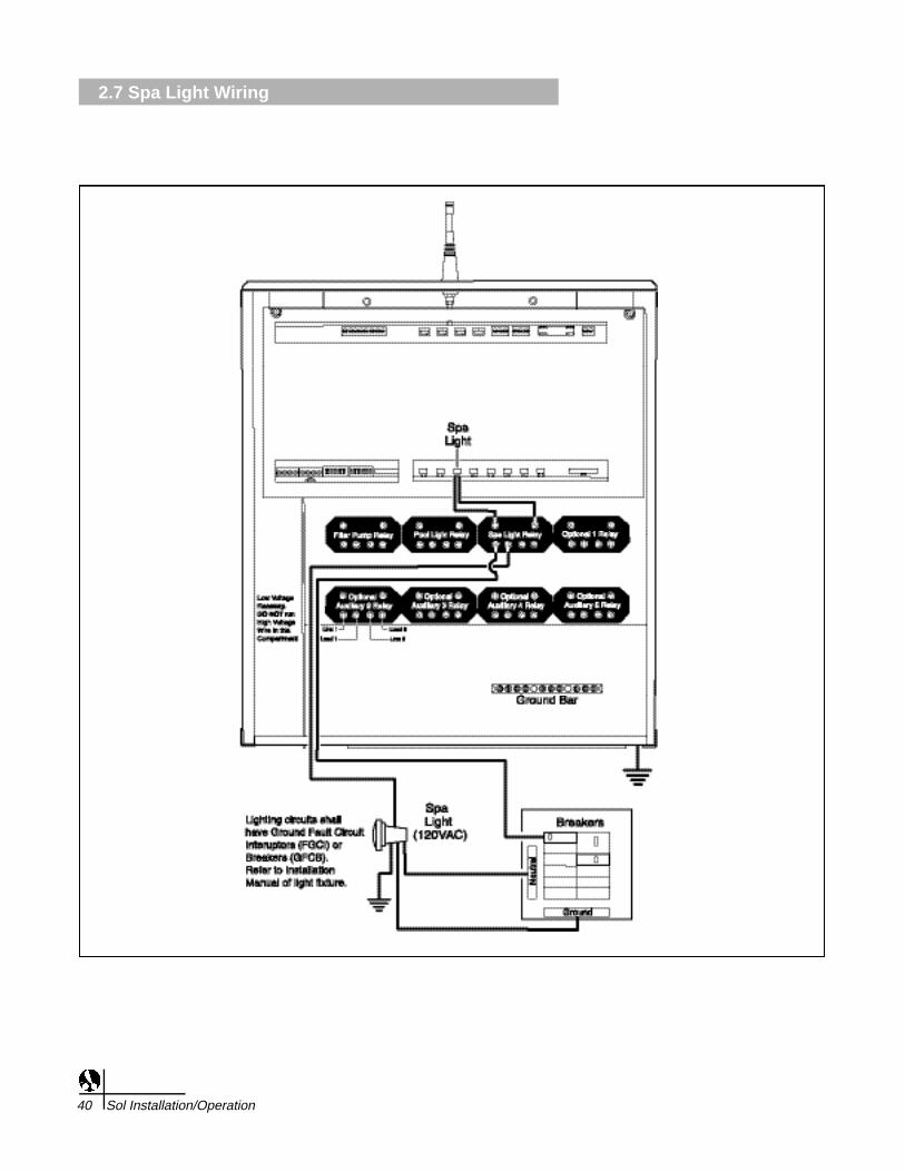
Spa Light Wiring
1. Ensure that equipment motors have built-in thermal protection.
2. Pull wire sized appropriately for each piece of equipment from theequipment to the enclosure.
3 . Each piece of equipment should have its own high voltage relay. Insome cases, a relay may be shared by more than one piece ofequipment as long as total amperage draw does not exceed 25 A m p s91500 watts).
4. Connect the equipment grounds.
5. A green colored terminal or a terminal marked G, GR, Ground,Grounding, or is located inside the supply terminal box orcompartment. To reduce the risk of electric shock, this terminal mustbe connected to the ground means in the electric supply servicepanel with a continuous copper No. 8 AWG bare, covered orinsulated wire per NEC Article 250-122.
6. A bonding lug is provided on the external surface of the supplyterminal box or compartment. To reduce the risk of electric shock,connect the local common bonding grid in the area of the pool orspa to this terminal with an insulated or bare copper conductor notsmaller than No. 8 AWG.
7. Wire the relay of the equipment being used, installing additional relays when necessary.
8. For each 240 V rated equipment: Wire the line power to the two lineterminals of a relay and wire the equipment to the two loadterminals.
9 . For each 120 V rated equipment: Wire power to a line terminal andthe equipment to an adjacent load terminal.
10. Feed the relay plugs through the holes into the low voltagecompartment.
Contact Ratings - Not to Exceed
INSTALLATION2.7 Spa Light Wiring
Sol Installation/Operation 41
Standard Relay: 3 H.P. at 240 VAC1.5 H.P at 120 VAC25 Amps1500 Watts
IMPORTANT: Do not turnon electrical power until allhigh voltage and lowvoltage connections havebeen made. Failure tofollow this precaution canresult in permanentdamage to the commandcenter, transformer orcircuit board.Note: All electricalequipment must be fivefeet or more from thepool/spa and comply withall national, state and localcodes.

2.8 Fiber Optic Lights Wiring
42 Sol Installation/Operation

Fiber Optic Light Wiring
1. Ensure that equipment motors have built-in thermal protection.
2. Pull wire sized appropriately for each piece of equipment from theequipment to the enclosure.
3 . Each piece of equipment should have its own high voltage relay. Insome cases, a relay may be shared by more than one piece ofequipment as long as total amperage draw does not exceed 25 A m p s91500 watts).
4. Connect the equipment grounds.
5. A green colored terminal or a terminal marked G, GR, Ground,Grounding, or is located inside the supply terminal box orcompartment. To reduce the risk of electric shock, this terminal mustbe connected to the ground means in the electric supply servicepanel with a continuous copper No. 8 AWG bare, covered orinsulated wire per NEC Article 250-122.
6. A bonding lug is provided on the external surface of the supplyterminal box or compartment. To reduce the risk of electric shock,connect the local common bonding grid in the area of the pool orspa to this terminal with an insulated or bare copper conductor notsmaller than No. 8 AWG.
7. Wire the relay of the equipment being used, installing additional relays when necessary.
8. For each 240 V rated equipment: Wire the line power to the two lineterminals of a relay and wire the equipment to the two loadterminals.
9. Feed the relay plugs through the holes into the low voltagecompartment.
Contact Ratings - Not to Exceed
INSTALLATION2.8 Fiber Optic Lights Wiring
Sol Installation/Operation 43
IMPORTANT: Do not turnon electrical power until allhigh voltage and lowvoltage connections havebeen made. Failure tofollow this precaution canresult in permanentdamage to the commandc e n t e r, t r a n s former orc i rcuit board .N o t e : All electricalequipment must be five fe e tor more from the pool/spaand comply with alln a t i o n a l , state and localc o d e s .
When fiber optic lighting isused, Dip Switch 7 in Bank1 should be in the ONposition.
In place of Pool Light, amenu pick for Fiber will bedisplayed. Pressing thiswill allow the user controlof the fiber opticilluminator and color wheelpower. The illuminatorpower must be connectedto the Pool Light Relayoutput and the color wheelpower must be connectedto the Spa Light Relayoutput.
Standard Relay: 3 H.P. at 240 VAC1.5 H.P at 120 VAC25 Amps1500 Watts

2.9 Cleaner Booster Pump Wiring
44 Sol Installation/Operation
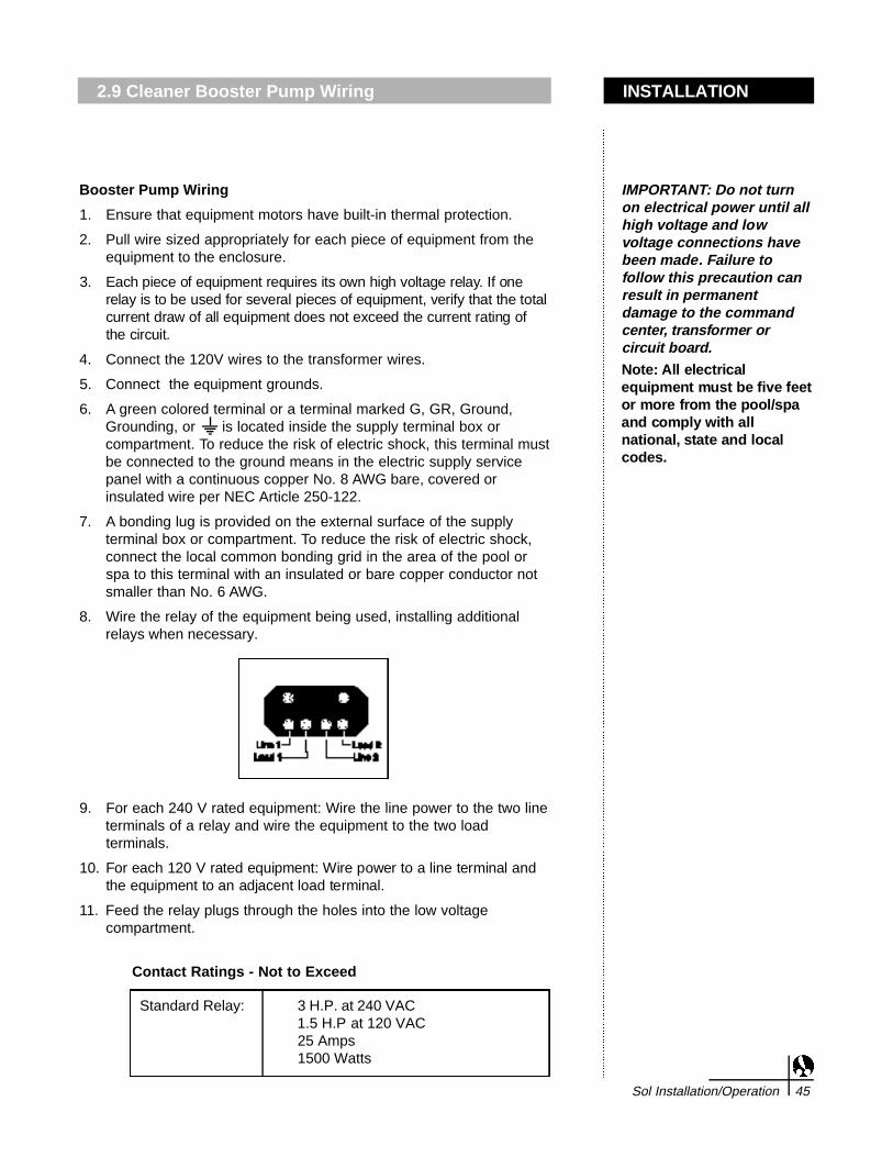
Booster Pump Wiring
1. Ensure that equipment motors have built-in thermal protection.
2. Pull wire sized appropriately for each piece of equipment from theequipment to the enclosure.
3 . Each piece of equipment requires its own high voltage relay. If onerelay is to be used for several pieces of equipment, verify that the totalcurrent draw of all equipment does not exceed the current rating ofthe circuit.
4. Connect the 120V wires to the transformer wires.
5. Connect the equipment grounds.
6. A green colored terminal or a terminal marked G, GR, Ground,Grounding, or is located inside the supply terminal box orcompartment. To reduce the risk of electric shock, this terminal mustbe connected to the ground means in the electric supply servicepanel with a continuous copper No. 8 AWG bare, covered orinsulated wire per NEC Article 250-122.
7. A bonding lug is provided on the external surface of the supplyterminal box or compartment. To reduce the risk of electric shock,connect the local common bonding grid in the area of the pool orspa to this terminal with an insulated or bare copper conductor notsmaller than No. 6 AWG.
8. Wire the relay of the equipment being used, installing additional relays when necessary.
9. For each 240 V rated equipment: Wire the line power to the two lineterminals of a relay and wire the equipment to the two loadterminals.
1 0 . For each 120 V rated equipment: Wire power to a line terminal andthe equipment to an adjacent load terminal.
11. Feed the relay plugs through the holes into the low voltagecompartment.
Contact Ratings - Not to Exceed
INSTALLATION2.9 Cleaner Booster Pump Wiring
Sol Installation/Operation 45
Standard Relay: 3 H.P. at 240 VAC1.5 H.P at 120 VAC25 Amps1500 Watts
IMPORTANT: Do not turnon electrical power until allhigh voltage and lowvoltage connections havebeen made. Failure tofollow this precaution canresult in permanentdamage to the commandc e n t e r, t r a n s former orc i rcuit board .N o t e : All electricalequipment must be five fe e tor more from the pool/spaand comply with alln a t i o n a l , state and localc o d e s .

2.10 Heater Wiring
46 Sol Installation/Operation
Sol Low VoltageHeater Connection
For Hayward Heaters
For Teledyne Laars Heaters

Sol Low Voltage Heater Connection
1. Connect two 18 AWG wires, designed for use in hot environmentsto the 2-pin terminal bar on the circuit board labeled “HEATER.”
2. Run the wires through the low voltage raceway in the CommandCenter.
Hayward Heaters Wiring Guidelines
For HM2, Models 150, 200, 250, 300, 350 and 400
1. Remove the heater service door.
2. Remove the factory-installed wire nuts located between the two redwires labeled "Connection for Field Installed Control Switch".
3. Wire nut the two heater wires from the command center circuitboard to the two red wires as shown in the diagram.
4. Turn the thermostat selector switch to either the ON, HIGH or SPAposition and set the heater thermostat(s) to the maximum setting.
Teledyne Laars Heater Wiring Guidelines
For Series 2 Model ESC Pool and Spa Heaters
1. Remove the heater service door.
2. Remove the factory-installed wire between Terminal 1 and Terminal2 on the terminal strip.
3. Connect the wires from the command center circuit board to the twoterminals. Teledyne Laars requires the heater hookup wires to be14-AWG copper with a temperature rating of 105° or higher.
4. Turn the thermostat selector switch to either ON, HIGH or SPA andset the heater thermostat(s) to the maximum setting.
INSTALLATION2.10 Heater Wiring
Sol Installation/Operation 47

2.10 Heater Wiring
48 Sol Installation/Operation

Purex Heater Wiring Guidelines
For MiniMax and Tropical Isle Pool and Spa Heaters
1. Remove the heater service door.
2. Separate the black wire (common) from each other (see thediagram below).
3. Connect the wires from the command center circuit board to the twoblack wires as shown. The violet and red wires will remain unused.
4. Turn the heater switch to the ON position and set the heaterthermostat(s) to the maximum setting.
5. When connecting a Polaris Sol 1000 Wireless Remote Controller toa Purex heater, Purex requires that you install the low voltagethermostat wires in a separate conduit from ANY line voltage wires. Failure to do so will cause the thermostat relay to react erratically.
AquaCal TropiCal Heat Pump Connections
The thermostat on the TropiCal heat pump is wired in parallel to thethermostat on the Sol controller. Unlike most heaters and heat pumps,the thermostat must be turned all the way down to remove it from thesystem and allow Sol full control.
1. Connect two 18 AWG wires, designed for use in hot environments,to the 2-pin terminal bar on the circuit board labeled “HEATER”.
2. Locate the Controller Options terminal block inside the heat pumps electric box.
3. Connect the 18 AWG wires from the controller to the Controller Options terminals designated A and B.
4. Turn the heat pumps thermostats all the way down.
5. Set the heat pumps thermostat selector switch to the off position.
Raypak Heater Wiring Guidelines
For RS2100
1. Remove the heater service door.
2. Cut the factory-installed wire.
3. Wire-nut the two heater wires from the command center circuitboard to the two wires.
4. Turn the heater switch to the ON position and set the heaterthermostat(s) to the maximum setting.
5. For Sol controllers located more than ten feet from the heater,RayPak recommends the use of the RayPak Interface Module Kit(p/n 005386) to eliminate outside interference.
INSTALLATION2.10 Heater Wiring
Sol Installation/Operation 49
2.11 Other Natural Gas and Propane Gas Heater Wiring
50 Sol Installation/Operation

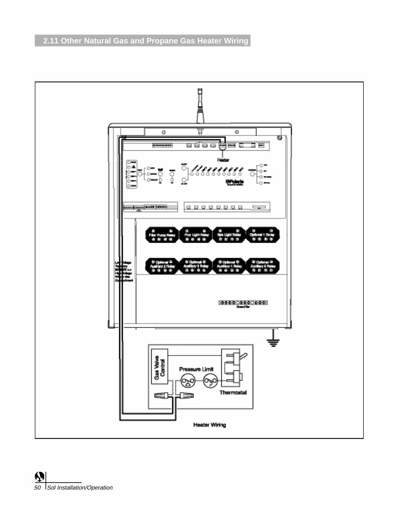
Other Natural Gas Heaters and Propane Heaters1. Connect two 18 AWG wires (designed for hot environments) to the
appropriate terminals on the heater terminal bar.
2. Connect two heater wires from the command center circuit board tothe heater in series as if wiring a fireman's switch or heater delay.
3. Do not disconnect the high limit or pressure switches.
4. Turn the heater thermostat(s) to the maximum setting.
5. Turn the heater switch to the ON position.
6. Connect the heater to the low voltage terminal on the circuit board(all gas heaters or heat pumps with thermostatic circuitry of 24 VACor less). Do not disconnect the high limit or pressure switchesinside the heater.
Note: For connections to a specific heater brand, see the heaterwiring guidelines and consult the heater or heat pump manufacturer.
a. Gas or Propane Heaters Connections To Circuit Board
1. Connect two 18 AWG wires, designed for use in hotenvironments, to the 2-pin terminal bar on the circuit boardlabeled “HEATER”.
2. Bring the two wires from the circuit board to the heater andwire nut in series with the heater circuitry as if wiring afireman’s switch or heater delay. (for heaters with dualthermostats and a three position switch (Pool/Off/Spa), thetwo control wires must be connected to one side of thethree positions switch (Pool or Spa) and that position mustbe the one turned on in step 4 below.
3. Turn the heater thermostat to maximum.
4. Turn the heater toggle switch on.
5. Re-light the pilot light (if necessary) before proceeding tothe next step.
INSTALLATION2.11 Other Natural Gas and Propane Gas Heater Wiring
Sol Installation/Operation 51

2.12 Electric Heater and Heat Pump Wiring
52 Sol Installation/Operation
Electric Heater and Heat Pump WiringDo not use these guidelines to connect a heater with a high voltage(120/240 VAC) thermostat into a low voltage terminal bar.
High Voltage Electric Heater
1. A high voltage electric heater must be connected to a high voltageauxiliary relay inside the high voltage wiring area of the Solcommand center.
2. Turn the heater thermostat setting to maximum.
3. Turn the heater power position to the on position.
Note: The heater connections to the high voltage relay acts only as a switch and should not be used for the supply line voltage.
Heat Pumps1. Connect two 18 AWG wires, designed for use in hot environments,
to the 2-pin terminal bar on the circuit board labeled “HEATER.”
2. Bring the two wires from the circuit board to the heat pump and wirenut in series with the heat pump circuitry as if wiring a fireman’sswitch or heater delay. (Consult heat pump manufacturer forspecific instructions.).
3. Turn the heat pump thermostat to maximum.
4. Turn the heat pump toggle switch on.
INSTALLATION2.12 Electric Heater and Heat Pump Wiring
Sol Installation/Operation 53
2.13 Solar System Wiring
54 Sol Installation/Operation

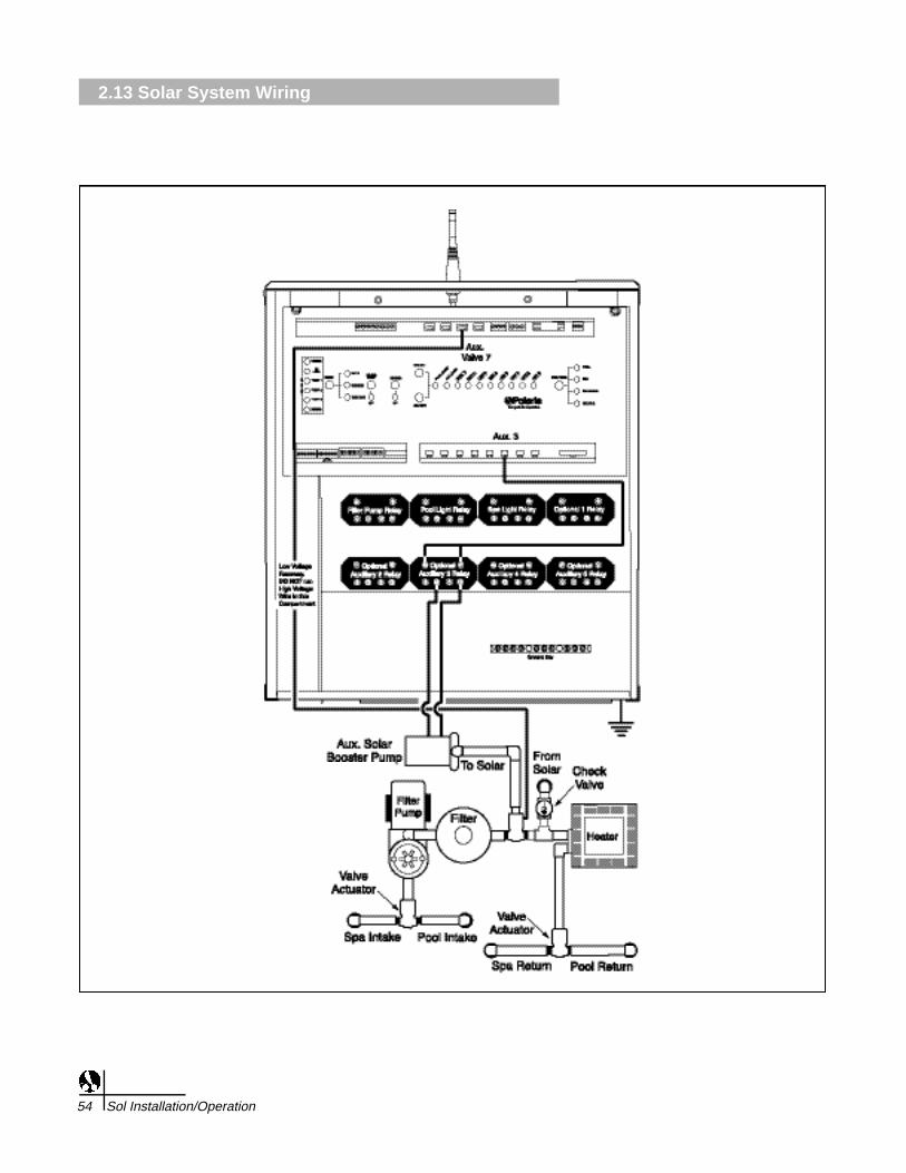
Solar System Wiring
Note: Do not coil the valve actuator cable inside the command center.
1. Run the valve actuator wires back to the low voltage compartmentof the command center, through the low voltage raceway, and plugthe solar valve actuator into the socket labeled AUX VALVE 7.
2. Turn Dip Switch 4 in Bank 1 to the ON position.3. If there is a booster pump on the Solar system, the booster pump
should be wired to Auxiliary 3 and Dip Switch 5 in Bank 1 should beturned on.
INSTALLATION2.13 Solar System Wiring
Sol Installation/Operation 55

2.14 Blower Wiring
56 Sol Installation/Operation

Blower Wiring1. Ensure that equipment motors have built-in thermal protection.
2. Pull wire sized appropriately for each piece of equipment from theequipment to the enclosure.
3 . Each piece of equipment requires its own high voltage relay. If onerelay is to be used for several pieces of equipment, verify that the totalcurrent draw of all equipment does not exceed the current rating ofthe circuit.
4. Connect the 120V wires to the transformer wires.
5. Connect the equipment grounds.
6. A green colored terminal or a terminal marked G, GR, Ground,Grounding, or is located inside the supply terminal box orcompartment. To reduce the risk of electric shock, this terminal mustbe connected to the ground means in the electric supply servicepanel with a continuous copper No. 8 AWG bare, covered orinsulated wire per NEC Article 250-122.
7. A bonding lug is provided on the external surface of the supplyterminal box or compartment. To reduce the risk of electric shock,connect the local common bonding grid in the area of the pool orspa to this terminal with an insulated or bare copper conductor notsmaller than No. 6 AWG.
8. Wire the relay of the equipment being used, installing additional relays when necessary.
9. For each 240 V rated equipment: Wire the line power to the two lineterminals of a relay and wire the equipment to the two loadterminals.
1 0 . For each 120 V rated equipment: Wire power to a line terminal andthe equipment to an adjacent load terminal.
11. Feed the relay plugs through the holes into the low voltagecompartment.
Contact Ratings - Not to Exceed
INSTALLATION2.14 Blower Wiring
Sol Installation/Operation 57
IMPORTANT: Do not turnon electrical power until allhigh voltage and lowvoltage connections havebeen made. Failure tofollow this precaution canresult in permanentdamage to the commandc e n t e r, t r a n s former orc i rcuit board .N o t e : All electricalequipment must be five fe e tor more from the pool/spaand comply with alln a t i o n a l , state and localc o d e s .
Standard Relay: 3 H.P. at 240 VAC1.5 H.P at 120 VAC25 Amps1500 Watts

2.15 Jet Pump Wiring
58 Sol Installation/Operation

Jet Pump Wiring1. Ensure that equipment motors have built-in thermal protection.
2. Pull wire sized appropriately for each piece of equipment from theequipment to the enclosure.
3 . Each piece of equipment requires its own high voltage relay. If onerelay is to be used for several pieces of equipment, verify that the totalcurrent draw of all equipment does not exceed the current rating ofthe circuit.
4. Connect the 120V wires to the transformer wires.
5. Connect the equipment grounds.
6. A green colored terminal or a terminal marked G, GR, Ground,Grounding, or is located inside the supply terminal box orcompartment. To reduce the risk of electric shock, this terminal mustbe connected to the ground means in the electric supply servicepanel with a continuous copper No. 8 AWG bare, covered orinsulated wire per NEC Article 250-122.
7. A bonding lug is provided on the external surface of the supplyterminal box or compartment. To reduce the risk of electric shock,connect the local common bonding grid in the area of the pool orspa to this terminal with an insulated or bare copper conductor notsmaller than No. 6 AWG.
8. Wire the relay of the equipment being used, installing additional relays when necessary.
9. For each 240 V rated equipment: Wire the line power to the two lineterminals of a relay and wire the equipment to the two loadterminals.
1 0 . For each 120 V rated equipment: Wire power to a line terminal andthe equipment to an adjacent load terminal.
11. Feed the relay plugs through the holes into the low voltagecompartment.
Contact Ratings - Not to Exceed
INSTALLATION2.15 Jet Pump Wiring
Sol Installation/Operation 59
IMPORTANT: Do not turnon electrical power until allhigh voltage and lowvoltage connections havebeen made. Failure tofollow this precaution canresult in permanentdamage to the commandc e n t e r, t r a n s former orc i rcuit board .N o t e : All electricalequipment must be five fe e tor more from the pool/spaand comply with alln a t i o n a l , state and localc o d e s .
Standard Relay: 3 H.P. at 240 VAC1.5 H.P at 120 VAC25 Amps1500 Watts

2.16 Water Feature Pump Wiring
60 Sol Installation/Operation

Water Feature Pump Wiring1. Ensure that equipment motors have built-in thermal protection.
2. Pull wire sized appropriately for each piece of equipment from theequipment to the enclosure.
3 . Each piece of equipment requires its own high voltage relay. If onerelay is to be used for several pieces of equipment, verify that the totalcurrent draw of all equipment does not exceed the current rating ofthe circuit.
4. Connect the 120V wires to the transformer wires.
5. Connect the equipment grounds.
6. A green colored terminal or a terminal marked G, GR, Ground,Grounding, or is located inside the supply terminal box orcompartment. To reduce the risk of electric shock, this terminal mustbe connected to the ground means in the electric supply servicepanel with a continuous copper No. 8 AWG bare, covered orinsulated wire per NEC Article 250-122.
7. A bonding lug is provided on the external surface of the supplyterminal box or compartment. To reduce the risk of electric shock,connect the local common bonding grid in the area of the pool orspa to this terminal with an insulated or bare copper conductor notsmaller than No. 6 AWG.
8. Wire the relay of the equipment being used, installing additional relays when necessary.
9. For each 240 V rated equipment: Wire the line power to the two lineterminals of a relay and wire the equipment to the two loadterminals.
1 0 . For each 120 V rated equipment: Wire power to a line terminal andthe equipment to an adjacent load terminal.
11. Feed the relay plugs through the holes into the low voltagecompartment.
Contact Ratings - Not to Exceed
INSTALLATION2.16 Water Feature Pump Wiring
Sol Installation/Operation 61
IMPORTANT: Do not turnon electrical power until allhigh voltage and lowvoltage connections havebeen made. Failure tofollow this precaution canresult in permanentdamage to the commandc e n t e r, t r a n s former orc i rcuit board .N o t e : All electricalequipment must be five fe e tor more from the pool/spaand comply with alln a t i o n a l , state and localc o d e s .
Standard Relay: 3 H.P. at 240 VAC1.5 H.P at 120 VAC25 Amps1500 Watts

2.17 Suction Valve Installation
62 Sol Installation/Operation

Suction Valve Actuators InstallationDo not coil the valve actuator cable inside the command center. Run thevalve actuator wires back to the low voltage compartment of thecommand center, through the low voltage raceway, and plug them intotheir sockets.
Ensure that the suction valve actuator plugs into the "SUCTIONVALVE" socket.
Actuator Installation Instructions
1. Remove the knob, handle and four screws from the valve cover.
2. Align the splines of the valve actuator shaft over shaft of valve.
3. If the valve actuator is not aligned with the mounting holes on thevalve cover, rotate the valve actuator.
4. Use the four mounting screws provided to mount the valve actuatorto the valve cover.
5. Mount the valve handle and knob to the valve actuator.
6. Connect the cord into the command centercircuit board at the appropriate valve actuator socket.
7. If the valve rotates to the wrong position (180 degrees out ofphase), adjust the switch on the back of the valve actuator betweenthe ON 1 and ON 2 position. This will rotate the valve to the correctposition.
8. Refer to Actuator Valve Adjustment, section 2.22 to change campositions.
INSTALLATION2.17 Suction Valve Installation
Sol Installation/Operation 63

2.18 Return Valve Installation
64 Sol Installation/Operation
Return Valve Actuators InstallationDo not coil the valve actuator cable inside the command center. Run thevalve actuator wires back to the low voltage compartment of thecommand center, through the low voltage raceway, and plug them intotheir sockets.
Ensure that the return valve actuator plugs into the "RETURNVALVE" socket.
Actuator Installation Instructions
1. Remove the knob, handle and four screws from the valve cover.
2. Align the splines of the valve actuator shaft over shaft of valve.
3. If the valve actuator is not aligned with the mounting holes on thevalve cover, rotate the valve actuator.
4. Use the four mounting screws provided to mount the valve actuatorto the valve cover.
5. Mount the valve handle and knob to the valve actuator.
6. Connect the cord into the command centercircuit board at the appropriate valve actuator socket.
7. If the valve rotates to the wrong position (180 degrees out ofphase), adjust the switch on the back of the valve actuator betweenthe ON 1 and ON 2 position. This will rotate the valve to the correctposition.
8. Refer to Actuator Valve Adjustment, section 2.22 to change campositions.
INSTALLATION2.18 Return Valve Installation
Sol Installation/Operation 65
2.19 Water Feature Valve Installation
66 Sol Installation/Operation

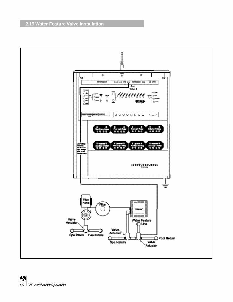
Water Feature Valve Actuators InstallationDo not coil the valve actuator cable inside the command center. Run thevalve actuator wires back to the low voltage compartment of thecommand center, through the low voltage raceway, and plug them intotheir sockets.
• Plug the actuator plug into “AUX 7” or “AUX 8” socket.
• Use the “AUX 8” socket if the actuator needs to close when the spais activated or if a solar system valve is used on “AUX7”.
Actuator Installation Instructions
1. Remove the knob, handle and four screws from the valve cover.
2. Align the splines of the valve actuator shaft over shaft of valve.
3. If the valve actuator is not aligned with the mounting holes on thevalve cover, rotate the valve actuator.
4. Use the four mounting screws provided to mount the valve actuatorto the valve cover.
5. Mount the valve handle and knob to the valve actuator.
6. Connect the cord into the command centercircuit board at the appropriate valve actuator socket.
7. If the valve rotates to the wrong position (180 degrees out ofphase), adjust the switch on the back of the valve actuator betweenthe ON 1 and ON 2 position. This will rotate the valve to the correctposition.
8. Adjust water flow to water feature by adjusting Actuator camposition.
9. Refer to Actuator Valve Adjustment, section 2.22 to change campositions.
INSTALLATION2.19 Water Feature Valve Installation
Sol Installation/Operation 67

2.20 Suction Cleaner Valve Installation
68 Sol Installation/Operation
Suction Cleaner Valve Actuators InstallationDo not coil the valve actuator cable inside the command center. Run thevalve actuator wires back to the low voltage compartment of thecommand center, through the low voltage raceway, and plug them intotheir sockets.
• Plug the actuator plug into “AUX 7” or “AUX 8” socket.
• Use the “AUX 8” socket if the actuator needs to close when the spais activated or if a solar system valve is used on “AUX7”.
Actuator Installation Instructions
1. Remove the knob, handle and four screws from the valve cover.
2. Align the splines of the valve actuator shaft over shaft of valve.
3. If the valve actuator is not aligned with the mounting holes on thevalve cover, rotate the valve actuator.
4. Use the four mounting screws provided to mount the valve actuatorto the valve cover.
5. Mount the valve handle and knob to the valve actuator.
6. Connect the cord into the command centercircuit board at the appropriate valve actuator socket.
7. If the valve rotates to the wrong position (180 degrees out ofphase), adjust the switch on the back of the valve actuator betweenthe ON 1 and ON 2 position. This will rotate the valve to the correctposition.
8. Adjust suction to cleaner by adjusting Actuator cam position.
9. Refer to Actuator Valve Adjustment, section 2.22 to change campositions.
INTRODUCTION2.20 Suction Cleaner Valve Installation
Sol Installation/Operation 69

2.21 Pressure Cleaner Valve Installation
70 Sol Installation/Operation

Pressure Cleaner Valve Actuators InstallationDo not coil the valve actuator cable inside the command center. Run thevalve actuator wires back to the low voltage compartment of thecommand center, through the low voltage raceway, and plug them intotheir sockets.
• Plug the actuator plug into “AUX 7” or “AUX 8” socket.
• Use the “AUX 8” socket if the actuator needs to close when the spais activated or if a solar system valve is used on “AUX7”.
Actuator Installation Instructions
1. Remove the knob, handle and four screws from the valve cover.
2. Align the splines of the valve actuator shaft over shaft of valve.
3. If the valve actuator is not aligned with the mounting holes on thevalve cover, rotate the valve actuator.
4. Use the four mounting screws provided to mount the valve actuatorto the valve cover.
5. Mount the valve handle and knob to the valve actuator.
6. Connect the cord into the command centercircuit board at the appropriate valve actuator socket.
7. If the valve rotates to the wrong position (180 degrees out ofphase), adjust the switch on the back of the valve actuator betweenthe ON 1 and ON 2 position. This will rotate the valve to the correctposition.
8. Adjust the water flow to cleaner by adjusting Actuator cam position.
9. Refer to Actuator Valve Adjustment, section 2.22 to change campositions.
INTRODUCTION2.21 Pressure Cleaner Valve Installation
Sol Installation/Operation 71

2.22 Actuator Valve Adjustments
72 Sol Installation/Operation
SpecificationsVoltage: 24 VACAmps: 0.65Torque: 250 inch poundsSize: L 7.5”, H 4.75”, W 4.25”Material: Housing - Noryl:
Gears - steelGrease: MoS2 LubricantCord Length: 15’Rated: Outdoor use

Actuator Valve Adjustments
Most installations do not require adjusting the valve actuator unless abypass is desired or the flow needs to be redirected.
1. Remove the valve actuator cover.
2. Unplug the cord from the command center circuit board.
3. Loosen the lock nut with a pair of pliers (this allows moving theadjustment cams).
4. To change the clockwise stop point of the valve actuator, turn theupper cam to the desired position. To change the counterclockwisestop point, turn the lower cam to the desired position.
5. Tighten the lock nut.
6. Reconnect the cord into the command center circuit base.
7. Using the toggle switch on the back of the valve actuator switch tothe ON 1 and ON 2 positions to verify that the new adjustment iscorrect.
8. Repeats steps 2-6 if further adjustment is required.
9. Replace the valve actuator cover.
INTRODUCTION2.22 Actuator Valve Adjustments
Sol Installation/Operation 73

2.23 Temperature Sensor Installation
74 Sol Installation/Operation
2.24.1 Water Temperature Sensor
2.24.2 Air Temperature Sensor
2.24.3 Solar Temperature Sensor

Connect the temperature sensors to the appropriate terminals on thecommand center circuit board.
Water Temperature Sensor - Drill a 3/8" hole in the pipe between thefilter pump and the filter. Insert the sensor and use the provided clampto hold it in place. Verify that the O-ring is securely placed around thesensor to ensure a watertight seal. Connect the sensor wires to the 6-pin terminal bar on the circuit board at the position marked "WATERTEMP".
Freeze/Ambient Air Temperature Sensor - Install the sensor outsideof the command center in an area where it will be subjected to shadedair temperature, but not to direct sunlight. Connect the sensor wires tothe 6-pin terminal bar on the circuit board at the location marked "AIRTEMP".
Solar Temperature Sensor (optional) - If there is a solar system, installthe solar sensor adjacent to the solar panels. Connect the sensor wiresto the 6-pin terminal bar on the circuit board at the location marked"SOLAR TEMP".
INSTALLATION2.23 Temperature Sensor Installation
Sol Installation/Operation 75

2.24 Low Voltage Accessory Installation
76 Sol Installation/Operation

To connect any low voltage (24 V or less) auxiliaries (such as landscapelighting), plug the transformer into any standard 120 V wall outlet. Cutone wire on the secondary side of the transformer and connect a lengthof 22 AWG wire to each end of the newly cut wires. Run the 22 AWGwires into the command center through the low voltage raceway andconnect them to the 3-pin terminal bar on the circuit board labeled"LOW VOLT AUX" (see the wiring diagram on page 16 or on the insideof the command center door). If the transformer for the lights includesan integrated timer, the trippers must be removed and the unit must beturned on.
1. Use the 3-pin terminal bar in a normally open (the connection willbe open to the auxiliary until the relay is energized) or a normallyclosed (the connection will be closed to the auxiliary until the relayis energized) configuration.
2. Connect the wires from the auxiliary to the left and center positionsof the terminal bar to turn on the auxiliary when the relay isenergized.(Normally open.)
3. Connect the wires from the auxiliary to the center and rightpositions of the terminal bar to turn off a piece of equipment whenthe relay is energized. (Normally closed.)
INSTALLATION2.24 Low Voltage Accessory Installation
Sol Installation/Operation 77

2.25 Charger Base Installation
78 Sol Installation/Operation

Angled Table BaseChoose a table or counter located inside the house or other weatherprotected area near a 120 volt electrical outlet. Plug the 9 volt walltransformer into the outlet.
Wall MountUnscrew the two screws that hold the table base to the charging baseand remove the table base. Position the charging base at the desiredwall location and mark the mounting holes on the wall. Drill holes at themarked location, using the appropriate drill bits for the mountinghardware selected. Plastic wall anchors should be used to prevent thescrews from pulling out of the wall. Plug in the transformer.
Hardwiring the Charging BaseIt is possible to hardwire the charging base to the command center. thiswill allow the remote to communicate with either the command center orbase, whichever is closest. A Sol control cable must be used for thehardwire process. It has a phone type plug on one end and free wireson the other end.
1. Use electrical conduit to protect the control cable as it runs underground or through concrete.
2. Cut the phone connector from the control cable end that connectsto the Command Center.
3. Plug the wire into the rear of the charging base.
4. Connect the wires to the 4 position terminal bar on the "CommandCenter" PCB labeled "External Devices." Pin 1 is on the left andPin 4 is on the right.
Pin 1: Black Pin 2: Red
Pin 3: Green Pin 4: Yellow
INSTALLATION2.25 Charger Base Installation
Sol Installation/Operation 79

2.26 Remote Control Battery Installation & Replacement
80 Sol Installation/Operation

Hand-held Remote Battery InstallationThe battery, battery cover, O-ring, and screws are all packaged with theremote.
1. Connect the battery to the remote control unit.
2. Place the O-ring around the battery cover. Install the battery coverand O-ring onto the back of the remote. Verify that the O-ring doesnot move and is not pinched between the cover and remote, or theremote will not be water resistant.
3. Secure the battery cover with the provided screws and tighten theme v e n l y, but do not overtighten.
N o t e : Once the useful battery life has been depleted, it will benecessary to replace the battery. You can expect the battery to lastbetween 3 and 5 years, but actual battery life will depend on thenumber of charging cycles completed. A Polaris battery (part numberS-35) must be used with the remote control unit. When replacing theb a t t e r y, always replace the O-ring at the same time. The O-ring willdeteriorate with age and wear which can compromise the waterresistance. Even a small flaw in the O-ring can be enough to allowwater to enter the remote.
INSTALLATION2.26 Remote Control Battery Installation & Replacement
Sol Installation/Operation 81

2.27 Remote Control Battery Charging
82 Sol Installation/Operation

The battery will require charging before use. Charge the battery for atleast 15 hours before use. With a full charge, the remote is able tooperate for up to 2 days (depending on the amount of usage). Werecommend the remote to be placed on the charging base at the end ofthe day to ensure a full charge for the next use. Always verify that theremote is sitting squarely on the charging base so that it will properlycharge. It is normal for the battery to discharge when not in use.
INSTALLATION2.27 Remote Control Battery Charging
Sol Installation/Operation 83

2.28 Command Center Backup Battery Installation
84 Sol Installation/Operation
Replacing the back up battery
1. Turn power off to the controller and accessories by turning thecircuit breakers protecting the equipment.
2. Remove the front panel to gain access to the battery.
3. Remove the battery and replace with a new one (CR-2032) makingsure the positive side of the battery is installed facing up.
4. Replace the front panel.
5. Restore power to the controller and all accessories by turning thecircuit breakers on.
6. Using the remote control, set the current time and date so that theschedules will resume.
INTRODUCTION2.28 Command Center Backup Battery Installation
Sol Installation/Operation 85
3.1 DIP Switch Settings
86 Sol Installation/Operation
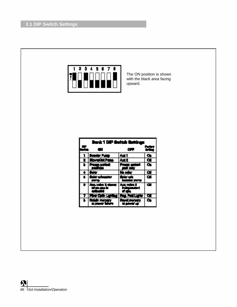
The ON position is shownwith the black area facingupward.
The DIP switches set operation parameters and define the externalequipment the command center controls.The Sol 1000 comes with twobanks of DIP switches, Bank 1 and Bank 2.
BANK 1
DIP Switch 1: (ON = Booster Pump Cleaner, OFF = Auxiliary 1)
If there is a booster pump cleaner installed, the DIP switch should be inthe ON position.
If the DIP switch is set to the ON position:
• The <CLEANER> choice will be activated in the pool menu;
• The main circulation pump will turn on whenever the booster pumpcleaner is turned on;
• The cleaner prime delay will prevent the booster pump from turningon until the main circulation pump has been on for 30 seconds;
• The cleaner turns off and access is disabled when the spa isenabled or when spillover is enabled;
• The booster pump turns off for four minutes when solar heat isenabled to allow air to be purged from solar collectors.
If the DIP switch is set to the OFF position: Auxiliary 1 will be activefrom the AUX menu and <CLEANER> will not appear in the pooloptions.
DIP Switch 2: (ON = Blower or Jet Pump, OFF = Auxiliary 2)
If there is a blower or a jet pump installed on the spa, the DIP s w i t c hshould be in the ON position.
If the DIP switch is set to the ON position:
• The <BLOWER> choice will be activated in the Spa menu.
<AIR JETS> will become an option in the spa options and in theAUX menu.
If the DIP switch is set to the OFF position, the Auxiliary 2 choice isactivated.
• If a spa light, blower and jet pump are installed on the same spa,use the DIP switch and the Auxiliary 2 relay to access one piece ofequipment from the spa menu.
DIP Switch 3: (ON = Freeze Protect Pool/Spa, OFF = Freeze ProtectPool Only)
If the DIP switch is in the ON position, and freeze protection is enabled,the pool and any other selected auxiliaries will be turned ON for 30minutes, and then water circulation will switch to the spa. This cycle willcontinue until the ambient temperature rises above the Freeze Protectiont e m p e r a t u r e .
If the DIP switch is in the OFF position, only the pool and selectedauxiliaries will be activated when freeze protection is enabled.
SET UP3.1 DIP Switch Settings
Sol Installation/Operation 87
3.1 DIP Switch Settings
88 Sol Installation/Operation
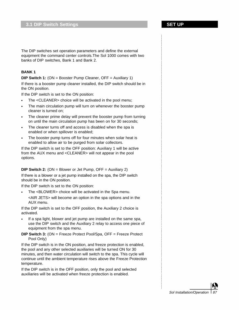
The ON position is shownwith the black area facingupward.

NOTE: This DIP switch does not enable freeze protection. This settingonly instructs how freeze protection will function when activated. Referto Owner’s Manual for further instruction on how to enable freezeprotection or how to assign different equipment to be protected.
DIP Switch 4: (ON = Solar, OFF = No Solar)
If there is solar heat on the pool/spa, turn this switch ON. <SOLAR> willappear as a choice from the Pool menu.
DIP Switch 5: (ON = Solar with Booster Pump, OFF = Solar withoutBooster Pump)
If there is a booster pump on the solar system, the switch should be inthe ON position. The booster pump should be wired to the Auxiliary 3relay.
If the solar system does not use a booster pump the DIP switch shouldbe in the OFF position.
DIP Switch 6: (ON = AUX) valve 8 closes when spa is activated. (OFF= AUX) valve 8 functions independently of spa).
Turn DIP switch ON to turn off a valve connected to AUX 8 wheneverthe spa is turned on. You must activate “AUX 8” on the hand-heldRemote for this function to operate.
DIP Switch 7: (ON = Fiber Optic Lighting; OFF = Traditional PoolLighting)
If the DIP switch is in the ON position, the controller will be set to utilizethe fiber optic lighting. In place of Pool Light, a menu pick for FIBER willbe displayed. Pressing this will allow the user control over the fiberoptic illuminators power and color wheel power. The illuminator powermust be connected to the POOL LIGHT relay output on the circuit boardand the color wheel power must be connected to the SPA LIGHT relayoutput.
If the DIP switch is in the OFF position, the traditional pool lighting willbe used and a POOL LIGHT and SPA LIGHT item will be present in therespective menus for independent control over each light.
SET UP3.1 DIP Switch Settings
Sol Installation/Operation 89

3.1 DIP Switch Settings
90 Sol Installation/Operation
The ON position is shownwith the black area facingupward.

DIP Switch 8: (ON = Retain Memory at Power Failure; OFF = ResetMemory at Power Up)
• If the user-defined labels and schedules are to be stored in theevent of a power outage, this DIP switch should be in the ONposition.
• If the labels and schedules are to be erased in the event of a poweroutage, the switch should be in the OFF position. This f e a t u r eshould be used if it was desired to restore the memory to factorydefaults and erase all labels and programs.
BANK 2
DIP Switch 1: (ON = Pool only; OFF = Pool/Spa combination)
If the DIP switch is ON, the controller will be set for a pool onlyinstallation and all SPA functions will be disabled.
If the DIP switch is OFF, the controller will be set for a Pool/Spacombination.
DIP Switch 2: (ON = 2 Speed Pump; OFF = 1 Speed Pump)
If the DIP switch is ON, the controller will utilize both speeds of a 2-speed pump.
If the DIP switch is OFF, the controller will use a traditional single speedpump.
DIP Switch 3: (ON = Low speed heating; OFF = High speed heating)
If the low speed of the pump will supply enough water to the heater toprevent the heater from rapid-cycling, then this switch can be ON.Otherwise, the system should only heat with the pump in the HighSpeed and the switch should be OFF.
Factory DIP Switch Setting
SET UP3.1 DIP Switch Settings
Sol Installation/Operation 91
Bank 1 Bank 2
#1 = On #1 = Off#2 = Off #2 = Off#3 = On #3 = Off#4 = Off #4 = Off#5 = Off #5 = Off#6 = Off #6 = Off#7 = Off #7 = Off#8 = On #8 = Off

3.2 Turning on the Command Center
92 Sol Installation/Operation

Turning on the Command Center
Complete the following steps to perform the initial startup procedures
1. Turn on power to the command center at the main electrical servicepanel.
2. The circuitry will perform a self-diagnostics test. The LEDs willsequentially turn on and off, starting from the lower right LED to theupper left LED. Each LED will light a second time and remain on untilthe one is lit. They will all turn off, with the exception of the power light.This startup test can be used once the installation is complete to quicklyverify that all of the LEDs are functioning.
3. At the command center, press MODE once to select the service mode.
4. Press FUNCTION on the right side of the status board to place thecommand center into spa mode. Each time the function button ispressed, the command center will progress to the next function mode.
Note: When transitioning from one mode to another, the valve actuatorswill turn. Verify that the intake and return valves rotate to the correctposition. In POOL mode, the suction and return valves should bepositions to draw water from the pool and return to the pool. For SPAmode, the suction valve should be positioned to return water to the spa.for SPA DRAIN, the suction valve should be positioned to draw waterfrom the spa and the return valve should be positioned to return waterto the spa.
If either valve is in the wrong position, flip the toggle switch on the backof the actuator to rotate it into the correct position. If the valve actuatorsare not set properly, the valve diverter may not properly close allowingwater to be drawn from or returned to a different location than expected.Verify that the valve rotates to the proper position. If the valve does notrotate to the proper position, refer to the instructions included with thevalve actuator to adjust the alignment.
5. Turn on the individual pieces of equipment to verify that they arefunctioning properly:
a. Press FILTER PUMP to turn on the main circulation pump.
b. Press HEATER to verify that the heater ignites. When in the servicemode, the safety interlocks are disabled. Although the heater can betested in the Service mode, it is possible to shut the pump off causing permanent damage to the heater. Always allowsufficient time for the pump to run so the heater can cool down beforeshutting the pump off or exiting the Service mode.
c. Turn on each of the auxiliaries to verify they are functioning properly. Toturn on an individual auxiliary, press SELECT until the LED for thatauxiliary flashes. The flashing of the LED indicates the selection of thatparticular auxiliary. Press the ON/OFF button to turn the selectedauxiliary on or off. To select another auxiliary, simply press SELECTuntil the appropriate auxiliary LED is flashing. When you reach the endof the bank of 10 auxiliary LEDs, the select button will scroll back to thepool light auxiliary.
SET UP3.2 Turning on the Command Center
Sol Installation/Operation 93

3.2 Turning on the Command Center
94 Sol Installation/Operation

6. Check the sensor status lights. If the light is on, check theappropriate sensor wiring and connections. If there is notemperature sensor hooked up, the red LED will be on. If the LED islit, but the sensor is installed, the wiring should be checked to verifythat the connection is sound before replacing the sensor. If theERROR light is on, please contact an authorized service technicianbefore proceeding.
7. Press MODE twice to bypass the TIME-OUT mode and enter theAUTO mode. When leaving SERVICE or TIME-OUT`mode, thecommand center will turn off all activated pieces of equipment andposition the valves for pool mode. Note: Turning the pump off whilethe heater burners are hot can cause permanent damage to theh e a t e r. Allow cool water to flow through the heater for at least fourminutes prior to turning off the filter pump. Once cool, the commandcenter can be placed in auto mode.
8. Once the auxiliary equipment has been installed, use the pre-printed labels provided to rename the auxiliaries used. There arealso some blank labels that can be written on with a permanentmarker in the event that the equipment is not listed.
SET UP3.2 Turning on the Command Center
Sol Installation/Operation 95

3.3 Remote Control Training
96 Sol Installation/Operation

The remote has been trained at the factory to communicate only withthe command center it has been shipped with. The training of aremote to a specific command center is not lost in the event of apower failure or dead battery in the remote.In the unlikely event that communication cannot be established or ifadditional remotes were purchased to be used with the same controller,follow the instructions below.1. At the command center, press the Mode button until the TIME-OUT
LED is lit.
2. Press and hold Button 1 on the remote. See the diagram below.
3. While pressing Button 1, press the POOL button.
A series of waves will appear on the display. When the message"Requesting System ID - Loading X/127 (counts from 1 to 127)"appears, the buttons can be released.
If the waves appear on the display without the “Requesting SystemID” message, the POOL button was pressed before Button 1.Release the buttons and try again, making sure that Button 1 ispressed first.
4. Once the remote has been trained successfully, push the Modebutton at the command center until the AUTO MODE LED is lit.Press the <POOL>, <SPA>, or <AUX> buttons to establishcommunication between the remote and command center and verifyproper remote functionality.
Note: It is possible that unsuccessful communication attempts willoccur if multiple functioning remotes are in the same vicinity. If oneof the remotes has been trained to the command center, disconnectthe battery or position the remote far enough from the commandcenter so the signal is too weak to communicate with the commandcenter.
SET UP3.3 Remote Control Training
Sol Installation/Operation 97

3.4 Charging Base Training
98 Sol Installation/Operation
The charging base has been trained at the factory to communicate withthe remote with which it has been shipped with. It communicates withthe remote for paging operations. To test the training, plug it into a 120Velectrical outlet and press PAGE. The remote should begin to beep inresponse to the page signal. If the remote does not beep perform thefollowing steps:
1. Verify that the remote is trained.
2. At the command center, press the Mode button until the TIME-OUT-LED is lit.
3. Connect the provided power supply to the charging base, but do not plug it into a 120V electrical outlet.
a. Press and hold the PAGE button on the charger, but do not plugtransformer into the wall.
b. While pressing PAGE on the charging base, plug the powersupply into a 120V electrical outlet.
c. If the charging base communicates successfully with thecommand center, the LED on the charging base will startflashing green.
4. If the charging base does not successfully communicate with the command center, the LED will flash orange.
5. If the training was unsuccessful, move the charging base to alocation closer to the command center and perform step 3 again.Power the charging base at a location closer to the commandcenter. The same issues outlined on page 15 (CommunicationRange) that may cause poor radio communication, may also causepoor reception between the charging base and the commandcenter.
If the training continues unsuccessfully, contact our CustomerService Department toll-free at 1-800-VAC-SWEEP (USA andCanada only) or (760) 599-9600, Monday through Friday, 7:30amto 5:00 pm, PST.
SETUP3.4 Charging Base Training
Sol Installation/Operation 99

3.5 Antenna Repeater
100 Sol Installation/Operation
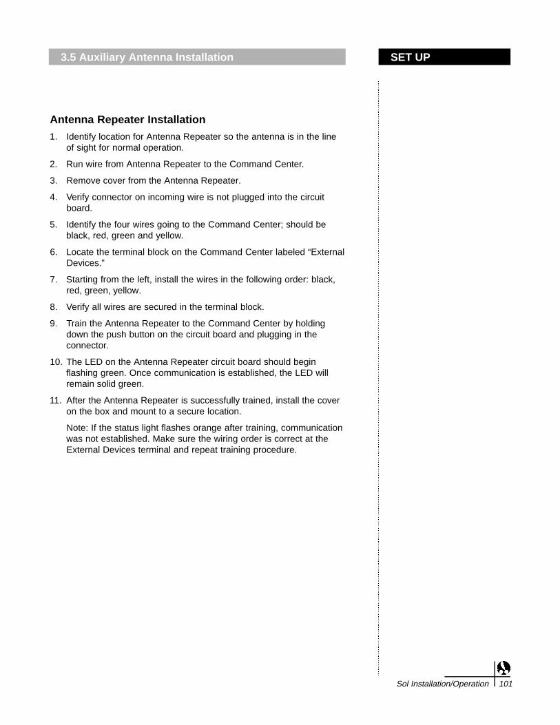
Antenna Repeater Installation
1. Identify location for Antenna Repeater so the antenna is in the lineof sight for normal operation.
2. Run wire from Antenna Repeater to the Command Center.
3. Remove cover from the Antenna Repeater.
4. Verify connector on incoming wire is not plugged into the circuitboard.
5. Identify the four wires going to the Command Center; should beblack, red, green and yellow.
6. Locate the terminal block on the Command Center labeled “ExternalDevices.”
7. Starting from the left, install the wires in the following order: black,red, green, yellow.
8. Verify all wires are secured in the terminal block.
9. Train the Antenna Repeater to the Command Center by holdingdown the push button on the circuit board and plugging in theconnector.
10. The LED on the Antenna Repeater circuit board should beginflashing green. Once communication is established, the LED willremain solid green.
11. After the Antenna Repeater is successfully trained, install the coveron the box and mount to a secure location.
Note: If the status light flashes orange after training, communicationwas not established. Make sure the wiring order is correct at theExternal Devices terminal and repeat training procedure.
SET UP3.5 Auxiliary Antenna Installation
Sol Installation/Operation 101

4.1 Command Center Panel Operation
102 Sol Installation/Operation

The Command Center is designed to access equipment from the remotecontrol unit. Accessing equipment from the command center should onlybe performed by a qualified pool service professional. When theequipment is accessed from the control panel, all built in safety delaysare disabled and permanent damage to equipment could result ifprecautions are not taken.
To activate equipment from the Command Center:
M O D E : Switches the controller from A U TO to SERVICE to TIME OUTm o d e .
AU TO : This is the mode that the Command Center should be set toenable remote operation. From this mode, the remote turns on or offany equipment and changes any system settings for schedules.
S E RV I C E : This mode turns equipment on or off from the CommandCenter and blocks input from the remote. The Command Center willremain in this mode indefinitely and must be switched to A U TOmode manually. While in this mode, the remote will be locked outfrom use and a message that says “SERVICE MODE ENABLED,SCHEDULES INACTIVE” will be displayed if the user tries to use ther e m o t e .
When entering the S E RV I C E m o d e, it is important to remember thatall of the equipment will turn off. To avoid any equipment malfunction,it is necessary to turn on the equipment manually at the CommandC e n t e r. For example, if the heater is firing and the service mode isentered, the heater can be seriously damaged unless water continues toflow through the heating elements. By manually turning on the filterpump, damage to the heater can be avoided.
Note: SERVICE mode is used if an indefinite period of time is neededto work on the equipment. TIME-OUT mode turns off the equipment fora period of two hours.
TIME OUT: This mode is similar to SERVICE mode except that thecommand center will remain in this mode for a period of 2 hours andthen switches automatically to A U TO mode. While in this mode, theremote will be locked out from use and a message that says “TIMEO U T MODE ENABLED, SCHEDULES INACTIVE” will be displayedif the user tries to use the remote.
How to check the Polaris Sol 1000 system
The equipment information on the LCD always indicates the correctstatus. Potential indications of a problem may actually be a faultysensor or loose connection. At system startup, the LEDs will cycle threetimes to verify that they are functioning properly. Once the cycle hasbeen finished, the lights of the active pieces of equipment should onlybe on. The red lights (TEMP 1 through TEMP 3) should only be onwhen the sensor has not been installed or when not working. If the redError light is on, a qualified Polaris service technician should be called.
F I LTER PUMP: Turns on or off the filter pump from the system.
OPERATION4.1 Command Center Panel Operation
Sol Installation/Operation 103

4.1 Command Center Operation
104 Sol Installation/Operation

H E AT E R: Enables the heater. The heater will only fire if water iscirculating through the system. In order for the heater to fire, the filterpump must also be turned on.
S E L E C T: Selects which auxiliary will be turned on by pressing ON/OFF.When in SERVICE or TIME OUT mode, the LED will flash indicatingthe current SELECT position. Pressing SELECT will advance to theright through each piece of equipment available. After you reachAUX 8 , pressing SELECT again will advance back to POOL L I G H T.
O N / O F F : Pressing ON/OFF activates the equipment indicated by theflashing LED. Pressing the button again will deactivate.
F U N C T I O N : Pressing this button will cycle through the four availablefunctions of the controller.
P O O L : This function sets the valves so suction from the pool returns thefiltered water back to the pool.
S PA : This function sets the valves so suction from the spa returns thefiltered water back to the spa.
S PA DRAIN: This function sets the valves so suction from the spareturns the filtered water back to the pool. Care must be taken whenusing this function because it is possible for the pump to run dryonce all the water is drained out of the spa. If the pump runs dry forprolonged periods, permanent damage can be done to the pump.
S PA FILL: This function sets the valves so suction from the pool returnsfiltered water back to the spa, resulting in a spillover effect from thespa back into the pool.
OPERATION4.1 Command Center Operation
Sol Installation/Operation 105
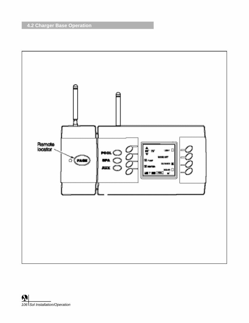
4.2 Charger Base Operation
106 Sol Installation/Operation

Charging the RemoteWhen the remote is not being used, place it onto the charger and it willautomatically be recharged for the next use. (Before the first use of theRemote, make sure the battery is fully charged for 15 hours.) When theremote is placed on the charger, the LED on the Charging Base isgreen, which indicates that it is communicating with the Remote andCommand Center. The light may also flash orange and green during theinitial setup and while paging the Remote.
If the battery strength is so low that the Remote will not activate afunction, you may hear a short beep but it will not respond to theelectronic command. You must recharge the Remote to be able to useit.
Place the Remote on the Charging Base and allow it to recharge fullybefore using it. If you must use the Remote before it is fully charged, itwill function normally while on the Charging Base, even with a lowbattery.
Paging OperationsTo locate a lost Remote, press the PAGE button on the Charging Base.The Remote will detect the signal and begin beeping for 60 seconds.
Once the Remote is located, pressing the POOL, SPA, or AUX buttonswill stop the beeping and activate the Remote. The Remote will onlybeep if there is sufficient battery strength. If the Remote has been offthe Charging Base long enough to drain the battery, then the locatorsignal will not function.
OPERATION4.2 Charger Base Operation
Sol Installation/Operation 107

4.3 Remote Control Operation
108 Sol Installation/Operation

Controller Overview
The Sol 1000 wireless remote controller is streamlined and easy to use.It is a portable control system that has been designed with the user inmind. Simply push either POOL, SPA or AUX to activate the remote.Once the remote is active, push the desired button to activate ordeactivate the chosen equipment.
Several sub-menus are available to walk you through the programinformation. The eight buttons surrounding the LCD correspond to themenu information. The buttons next to selections that have boxesindicate on or off (toggle) choices: X or ✔ for active, empty for inactive.
The Sol 1000 can turn the pool/spa equipment on and off in two ways:
1. Press the button to activate the selected equipment. The LCD willdisplay the appropriate menu to choose the desired settings.
2. Program the equipment to automatically turn on and off at specifictimes.
General Information
The wireless remote and charging base are designed with no wiringrequirements to assist in easy installation and exceptional mobility.
• The charging base is equipped with a 9V wall transformer that plugsinto any 120 volt electrical outlet. The charging base should belocated in the house or other weather protected areas.
• The charging base can be positioned on a table or counter usingthe angled table base, or can be permanently mounted to a wall. Topermanently mount to a wall:
1. Remove the two screws and the angled table base from thecharging base.
2. Position the charging base at the desired wall location.
3. Mark the location of the mounting holes on the wall.
4. Drill holes at the marked location, using the appropriate drill bits forthe mounting hardware selected. Use plastic wall anchors toprevent the screws from pulling out of the wall.
5. Attach the charging base to the wall using the appropriate hardware(not supplied).
OPERATION4.3 Remote Control Operation
Sol Installation/Operation 109

4.3 Remote Control Operation
110 Sol Installation/Operation

Water Resistance
The wireless remote is a water resistant unit. It is designed to withstandthe moisture of wet hands and splashing. It is not designed to resistperiods of prolonged exposure to water due to immersion, rain orsprinklers. This type of exposure could cause permanent damage. Theremote should never be placed on the charging base when wet.
Sunlight
Extended exposure to direct sunlight can permanently damage theremote LCD. The display is a liquid crystal type that, when subjected todirect sunlight for extended periods, will heat up and cause the displayto "black" out. If the display "blacks" out, remove the remote from thesunlight and let the display cool down until it has recovered and canbegin to function again. When using the remote outside, care should betaken to protect the display by keeping it in the shade or covering it witha towel.
Communication Range
Although reliable communication between the remote and the commandcenter can be expected at distances of up to 150 feet, the actual rangecan be affected by a number of different variables. The range can beaffected by elevation changes, environmental conditions or signaldisruptions caused by physical barriers. Barriers such as retaining walls,walls containing metal (such as re-bar), metal garage doors and heavyplant growth can absorb the radio signal and reduce range.
OPERATION4.3 Remote Control Operation
Sol Installation/Operation 111
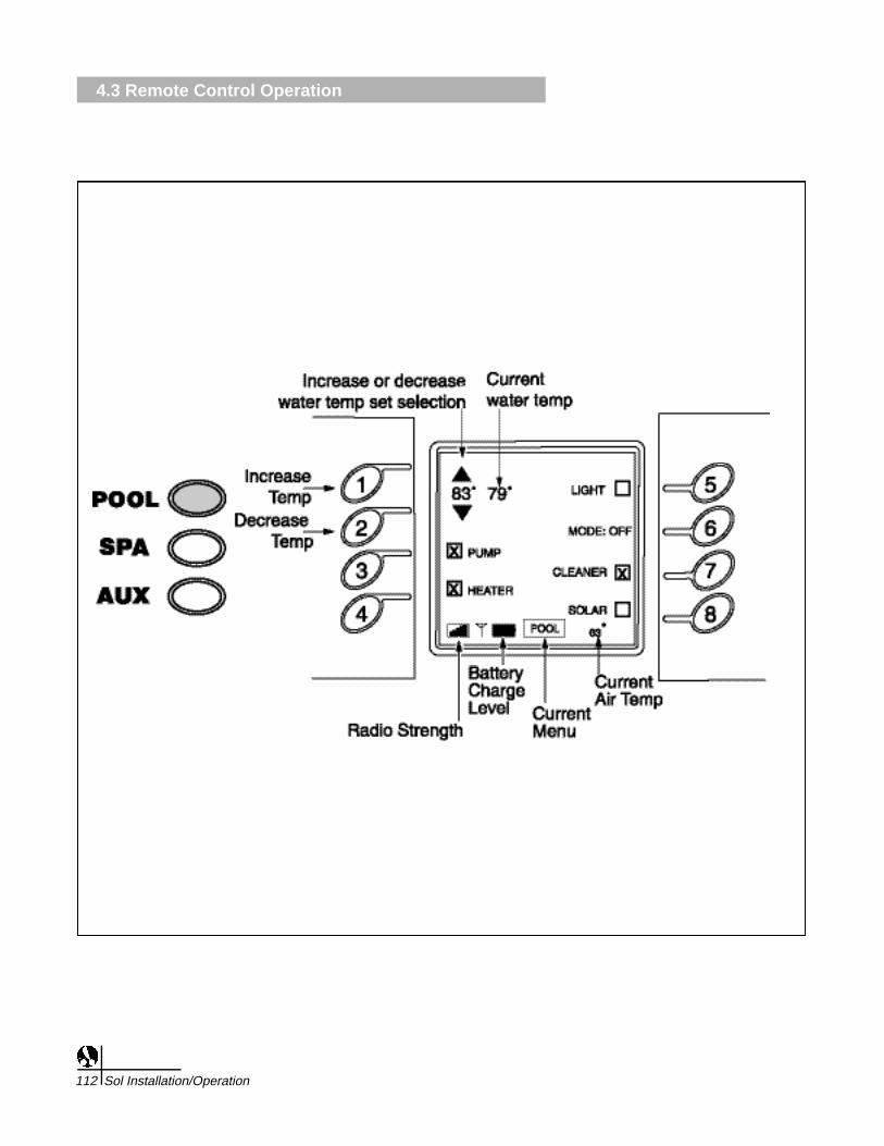
4.3 Remote Control Operation
112 Sol Installation/Operation

Using the Main Buttons
The LCD backlight stays lit for approximately 15 seconds and then turnso ff to save the life of the battery. Pressing any button will reactivate theb a c k l i g h t .
POOL BU T TO NThe pool button activates the menu for the pool functions. The functionsinclude the pool temperature, pump, heater, lights, mode activation,cleaner and solar. Once the pool menu has been entered, press thebuttons corresponding to the applicable functions to switch the functionon and off. Refer to the scheduling instructions on page 126 forprogramming details.The pool temperature can be adjusted from 68through 104-degrees.
H ow to control the pool/spa temperaturePress the pool or spa button. Using buttons 1 or 2, increase or decreasethe water temperature set point until the desired temperature is reached.Adjust if necessary. The current water temperature is shown next to theset point. (The circulation pump must be on to get an accuratetemperature.) The air temperature is shown at the bottom right of theL C D .
TO HEAT THE POOL,THE HEATER MUST BE ENABLED (an X in thebox next to H E AT E R). This tells the controller to look at the set pointwhen the filter pump comes on and if necessary turn on the heater. T h econtroller will only fire the heater if the pump is on and the heater isenabled. Turning the pump off (manually or with a schedule) will leavethe heater enabled and ready to heat the next time the pump is turnedo n .
Solar heating can be used by itself or to supplement the primary heateron the system. Solar heating will perform the same as the primaryheater. If the demand for heat is present and the solar heater isenabled, then water will flow to the solar panels for heating.
OPERATION4.3 Remote Control Operation
Sol Installation/Operation 113

4.3 Remote Control Operation
114 Sol Installation/Operation

SPA BUTTON
The spa button activates the menu for the spa functions. The functionsassociated with the spa menu include spa temperature, lights, air jets,and spillover. Refer to the scheduling instructions on page 126Programming Schedules.
When activated, the spa mode switches water circulation from pool tospa (on pool and spa combination models only). Turning on the spaactivates the filter pump (after a 45 second delay for valve rotation) anddeactivates the booster pump cleaner, if it is on. The spa must be on todisplay the spa temperature and/or heat the spa.
The spa temperature can be adjusted from 68 thru 104-degrees F.
Spillover will draw water from the pool and return all water back to thespa. In an elevated spa, this will create a waterfall effect as the waterspills over the spa edge and back into the pool.
How to control the spa
1. Press the spa button to activate the spa menu.
2. Press buttons 1 or 2 to change the spa temperature. Thetemperature shown next to the spa temperature is the actual watertemperature. See the following diagram.
3. All available selections such as lights, air jets, and spillover will bedisplayed on the LCD. Pressing buttons 3-7 will toggle theselection on and off.
HEATER box must be enabled (checked) for heating spa. If youhave a blower and a jet pump, only one device will activate whenthe AIR JETS option is selected. The device not controlled by AIRJETS can be activated from the AUX menu.The controller willautomatically turn the SPA off after 6 hours and return itself toPOOL Mode. This allows the pool to be filtered if the user forgets toturn the spa off when they are done using it.
4. If the controller is set up as a “pool only” control (no spa present onthe pool filtration system), this button will have no function andpressing it will have no effect. Review Appendix D and consult yourpool service professional to convert the controller to a pool onlycontrol.
OPERATION4.3 Remote Control Operation
Sol Installation/Operation 115

4.3 Remote Control Operation
116 Sol Installation/Operation

AUX BUTTONThe auxiliary button activates the auxiliary equipment menu. Up to eightauxiliaries can be programmed into the command center, depending onthe number of available relays. The auxiliary mode controls auxiliaryequipment such as additional lights not wired to the pool or spa lightc i r c u i t r y, cleaners, waterfalls, fountains, sprinklers and other backyardfeatures. Each auxiliary button can be custom labeled by accessing thelabels menu under the programming function. Matching labels aresupplied for the command center panel. The buttons should be labeled assoon as they are programmed. Consult your installer for the auxiliaryassignments and follow the labeling instructions on page 125 of thism a n u a l .
The position of the Command Center DIP switches may indicate thepiece of equipment associated with the auxiliary position. Certainauxiliary features will have to be connected to specific relay outputs onthe command center for proper operation. For example, if a boosterpump cleaner is installed, the booster pump must be connected to theAUX 1 output. DIP Switch 1 of Bank 1 must be placed in the ONposition so the controller can recognize the cleaner for properoperations. Consult your pool service technician and this manual forfurther information.
Multi-use buttonsThe eight non-labeled buttons on either side of the LCD control thedisplayed functions under each menu. They can be turned on and off bypressing the corresponding button. As the menu functions differ, thesebuttons will change with the selection.
OPERATION4.3 Remote Control Operation
Sol Installation/Operation 117
Note: Boxes that are grayed out indicate that the specificequipment is locked out, or not available for activation.

4.3 Remote Control Operation
118 Sol Installation/Operation

1. Heater "Short Cycling" Prevention
When the heater is activated and the desired temperature isreached, the heater will turn off and remain off until the temperaturefalls two degrees below the setpoint. This feature prevents theheater from cycling (i.e. heater turning off and on in rapidsuccession).
2. Cleaner Lockout
The pool cleaner will only activate when the system is in the poolmode (i.e. water circulating to the pool). The pool cleaner requiresthat water circulates to the pool for correct operation. Return to poolmode to activate the cleaner.
3. Spa Drain
The spa drain will only activate from the service mode.
4. When you turn on booster pump cleaner
Verifies the main circulation pump is running. If it isn't, the maincirculation pump will be turned on (or it can be done manually).
There is a 30-second prime delay to ensure the water is flowing tothe booster pump. The LCD will read "Prime Delay" during this time.
5. When you turn off the filter pump while booster pump is running
If both pumps are running, the booster pump can bemanually shutdown before the filter pump.
The filter pump can be shut down first and the controller willautomatically shut down the booster pump. The system is awarethat the booster pump cannot run without the circulation pump.
6. When you turn spa on or off or activate the spa spillover modewhile the filter pump is on
The filter pump will shut down for 45 seconds to allow sufficient timefor the valves to rotate.
7. When you activate spa or spa spillover mode
The filter pump will turn on automatically.
8. When the booster pump cleaner is active and spa or spaspillover mode is entered
The booster pump is automatically shut down. When the spa or spaspillover mode are cancelled, the controller will reactivate thebooster pump for the cleaner. If a cleaner schedule is active and itends during the spa or spa spillover mode, the booster pump willremain off when the spa or spa spillover mode is cancelled.
9. When the equipment is manually activated
Any existing schedule will be overridden. Remember to shut downthe piece of equipment that was manually activated when finished.If a schedule is active, the equipment will not shut down until thenext scheduled shut down time.
OPERATION4.4 Safety Delays and Lockouts
Sol Installation/Operation 119

10. When the spa mode is activated
The booster pump cleaner will be locked out.
11. When the heater is enabled and has recently fired
The heater will enter a 3-minute cool down mode. If the filter pump is shut down during the cool down, thepump will remain on until the delay is finished. The LCD will show the filter pump check box inactive.
1 2 . When you manu a l ly enter spa mode with no active spa sch e d u l e
The spa will have to be turned off manually if a spa schedule is not active. If it is not shut down, only thewater in the spa will be filtered, and the booster pump cleaner (or suction cleaner) will not be able to run.Turning off the filter pump will not reset the valves to pool mode. The valves will automatically return toPOOL mode after 6 hours.
4.4 Safety Delays and Lockouts
120 Sol Installation/Operation

Wait: Prime Delay
This message is displayed whenever the booster pump for a boosterpump cleaner is told to turn on. This delay ensures that the filtrationpump has been running for 30 seconds prior to turning on the boosterpump so that the booster pump has time to prime.
Wait: Valves TurningThis message is displayed whenever a valve is asked to rotate. Thisincludes switching from pool to spa to spillover mode or whenever anauxiliary valve (AUX 7 or AUX 8), including a solar valve, is asked torotate. This delay lasts for 45 seconds. During this delay, the filterpump will be shut off and will be restarted once the valves have stoppedturning.
Wait: Cool DownThis message is displayed whenever the heater is in a cool down cycle.A cool down cycle is initiated whenever the heater had recently beenfired and the pump was told to turn off. The controller will never allowwater flow to be stopped to a heater that had recently been fired. A cooldown cycle will most often be initiated when switching from spa to poolbecause the heater very likely had been heating the spa water. Duringthe cool down delay, the pump will continue to circulate water to theheater for three minutes before shutting off.
Wait: Purge DelayThis message is displayed whenever solar heating gets initiated andthere is a booster pump cleaner on the system. The booster pumpcleaner will shut down for a three minute period to allow all of thewater to be purged from the solar collectors. After the purge delay hascompleted, the booster pump will be turned back on.
Backup Battery Voltage Low, Replace BatteryThis message is displayed whenever the backup battery located in theCommand Center is failing. The message will be displayed every timethe remote is used as a gentle reminder to replace the battery.
Communication could not be established, Please try againThis message is displayed whenever the radio signal between theremote and Command Center gets lost. Reposition the remote orantenna and try again.
OPERATION4.5 Status Messages
Sol Installation/Operation 121

5.1 Program Menu
122 Sol Installation/Operation

Program MenuThe program menu is the main menu holding all programming sub-menus: schedules, clock, label, options and usermodes. To makechanges or additions to any programs, it is necessary to access theprogram menu before selecting the appropriate submenu. To access theprogram menu, simply hold down POOL, SPA or AUX until the programmenu appears.
The clock menu sets the internal clock of the Sol. It is important to setthe correct time and date so that the programming will operate properly.
1. Press and hold Pool, Spa or Aux until the program menu appears.See the Program Menu diagram on page 14.
2. Press button 2 of the program menu to select the Clock.3. Use buttons 5 or 6 to move the cursor back or forward to the hour
position. Buttons 1 or 2 will increase or decrease the selection.Verify the chosen time has the correct AM/PM designator..
4. Repeat this process for the minute, month, and year settings. Whenfinished, press <ENTER> to store in memory.
PROGRAMMING5.1 Program Menu
5.2 Setting the Clock
Sol Installation/Operation 123

5.3 Auxiliary Labeling
124 Sol Installation/Operation

The default auxiliary labels are AUX 1 thru AUX 8 and the user modesare labeled User Mode 1, User Mode 2 and User Mode 3. Once a pieceof equipment has been installed as an auxiliary, it is best to change thelabel for easy identification. If there is a booster pump cleaner and theCommand Center DIP switch is in the appropriate position (seeAppendix D on page 31), the label AUX 1 will automatically beprogrammed "CLEANER". If there is either a blower or a jet pump andthe DIP switch is in the appropriate position (see Appendix C), the labelfor AUX 2 will automatically be programmed "AIR JETS". You can re-name these if as needed.
1. Press and hold the POOL, SPA, or AUX button until the PROGRAMmenu appears. See the Program Menu diagram on page 14.
2. Press button 3 of the PROGRAM menu to select the LABELS.
3. The LCD will display the default name for the chosen auxiliary oruser mode. The cursor will blink under the active letter.
4. Use buttons 1 or 2 to scroll through the different letters andnumbers until the desired selection is reached, up to 15 characters..
5. Press buttons 5 or 6 to move the cursor to scroll through the cell.
6. Use buttons 3 or 4 to move between available equipment. Pressbutton 8 to enter the label into memory.
Note: If a mistake has been made, you must program a blankspace at the desired location to erase the original selection.
PROGRAMMING5.3 Auxiliary Labeling
Sol Installation/Operation 125

5.4 Schedules
126 Sol Installation/Operation

The schedule menu (button 1 of Program menu) can set operationtimes for any equipment controlled by the Sol. It is possible to programfor all days, weekends, weekdays, or any specific day of the week.Choose the specific time in hours and minutes. Each equipment canhave up to two on and off times per day. If two overlapping times areset for a piece of equipment, the equipment will turn on at the first ontime and turn off at the last off time.
It is important to take into consideration the operation of each piece ofequipment. Some of the equipment will need other equipment in orderto operate correctly. When scheduling, review all programmedequipment to see if there are any potential conflicts that will not allow forthe most efficient method of operation or may possibly eliminate theoperation altogether.
Note: SPA schedule will automatically turn the filtration pump on, so asecond schedule for the filter pump is not necessary.
For 2-speed pumps, a high speed filter pump schedule will override alow speed schedule.
1. Press either of the following buttons, POOL, SPA, or AUX and holddown until the program menu is displayed.
2. Press button 1 to select the Schedules.
3. The LCD will display two schedules with individual start and stoptimes, as well as the days of the week. These schedules control theautomation of all equipment.
• Buttons 1 and 2 increase or decrease the highlighted selection.
• Buttons 3 and 4 are used to move between the available pieces of equipment.
• Buttons 5 and 6 will move the cursor forward or backward to the next selection.
• Button 7 is used to quickly select or deselect the entire week for the program.
4. The same process will be used to select the On Minute, Off Hour,and Off Minute. After all schedules have been entered, pressENTER to store in memory.
PROGRAMMING5.4 Schedules
Sol Installation/Operation 127

5.4 Schedules
128 Sol Installation/Operation