wire harness installation instructions - carid.com · regulator, starter solenoid ... 1968 ignition...
TRANSCRIPT

Wire Harness Installation Instructions
For Installing:
#20121 Direct Fit Mustang Chassis Harness 1967-1968 22 Circuit
Manual #90556

1.0 INTRODUCTION
You have purchased what we at Painless Performance Products believe to be the most up-to-date and
easiest-to-install automotive wire harness on the market. It is designed for easy installation, even if you have no electrical experience
All Kits have a built-in-anti-theft feature. Removing the fuse labeled “coil” from the fuse block will prevent the vehicle from starting.
The proper fuses have been pre-installed in the fuse block. In addition, all wires are color-coded and
marked for easy identification. This will help you identify the different circuits during installation and later on if additions to the overall system are necessary. For fuse specifications and wire color designations,
see Section 8.1 and Table 8.1.
This Painless wire harness is designed to be used in 1967 - 1968 Ford Mustangs. All wire is 600 volt,
257F, TXL. Standard automotive wire is GPT, 300 volt, 176F, with PVC insulation.
This complete Classic Mustang wiring system has been designed with six major sections incorporated into
it:
ENGINE SECTION: Water temperature, oil pressure, tachometer, coil, choke, a/c compressor clutch
coil
HEADLIGHT SECTION: Includes high beam, low beam, park lights, right turn, left turn, horns, voltage
regulator, starter solenoid, battery feed and alternator.
GAUGE CLUSTER SECTION: Includes wires to connect to the gauges and to the indicator lights.
UNDER-DASH SECTION: Includes wires to connect heater-a/c switch, headlight switch, turn signal switch, radio, tachometer, ignition switch, cigar lighter, dimmer switch, brake switch, heater-a/c resistor,
a/c blower motor, wiper motor, wiper switch and wiper coordination switch.
INTERIOR LIGHTING SECTION: Includes right and left door jam switches, shift indicator light,
courtesy lights, and glove box.
REAR LIGHT SECTION: Includes taillights, stoplights, left and right turn signals, trunk light, backup
lights, license plate light, and fuel sending unit.
2.0 ABOUT THESE INSTRUCTIONS
The contents of these instructions are divided into major Sections, as follows:
1.0 Introduction 2.0 About These Instructions
3.0 Contents of Painless Wire Harness Kit 4.0 Tools Needed
5.0 Pre-Installation and Harness Routing Guidelines
6.0 Harness Installation Instructions 7.0 Specific Circuit Connections
8.0 Wire Connection Index and Fuse Requirements
Sections are divided into subsections and Paragraphs. Throughout these instructions, the Figure
numbers refer to illustrations and the Table numbers refer to information in table form. These are located in Sections or Paragraphs corresponding to the number. Always pay special and careful attention
to any Notes, especially those in the Tables, and any text marked Caution.

3.0 CONTENTS OF THE PAINLESS WIRE HARNESS KIT
The Main Wire Harness, with Fuse Block pre wired fuses and relays
installed. Pig Tails: Headlight Connector Harnesses, A/C Harness, Cluster
Harness, Front Lights Ground Harnesses, Tail Ground Harness and 1968 Turn Signal Harness.
Bag Kit: 1 pkg. of small and 1 pkg. of large Nylon Tie Wraps, Ballast Resistor, Maxi Fuse, Firewall Grommets, 1968 Ignition Switch and a Fuse Identification Label.
Parts Box containing Terminals, Splices, Spare Fuses etc.
Figure 3-1 Painless Wire Harness Kit
4.0 TOOLS NEEDED In addition to basic hand tools the following will also be needed:
Crimping Tool Note: Use a quality tool to avoid over-crimping. Wire Stripper Test Light or Volt Meter Small (10 amp or less) Battery Charger
5.0 PRE-INSTALLATION AND HARNESS ROUTING GUIDELINES
Installation of this wire harness consists mainly of two parts:
The physical routing and securing of the wire harness.
The connection of the individual circuits to their components.
These two major tasks are not separate steps, but are integrated together. In other words, you will route a section of wires and make that sections connections. Route the next section of wires and make those sections connections. The layout of this 1967-1968 Mustang harness will dictate how to physically route the harness in your automobile. The breakouts and connections are very close to the original Ford harnesses and should fit just as well if not better. It’s a good idea to document how the original harness was routed as this new one follows most of the same routing. The fitment greatly depends on to what extent you want to secure and conceal the harness. Painless offers some general guidelines and routing practices starting in Section 5.2, GENERAL installation instructions in Section 6.0, and precise instructions concerning the electrical connections you will make in Section 7.0. To help you begin thinking through the installation of your wire harness please read the following sections:
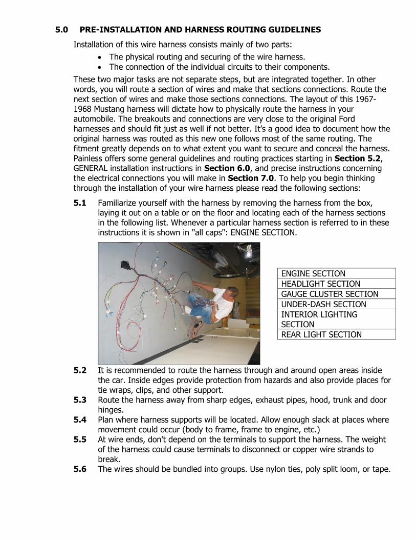
5.1 Familiarize yourself with the harness by removing the harness from the box, laying it out on a table or on the floor and locating each of the harness sections in the following list. Whenever a particular harness section is referred to in these instructions it is shown in "all caps": ENGINE SECTION.
5.2 It is recommended to route the harness through and around open areas inside the car. Inside edges provide protection from hazards and also provide places for tie wraps, clips, and other support.
5.3 Route the harness away from sharp edges, exhaust pipes, hood, trunk and door hinges.
5.4 Plan where harness supports will be located. Allow enough slack at places where movement could occur (body to frame, frame to engine, etc.)
5.5 At wire ends, don't depend on the terminals to support the harness. The weight of the harness could cause terminals to disconnect or copper wire strands to break.
5.6 The wires should be bundled into groups. Use nylon ties, poly split loom, or tape.
ENGINE SECTION
HEADLIGHT SECTION
GAUGE CLUSTER SECTION
UNDER-DASH SECTION
INTERIOR LIGHTING SECTION
REAR LIGHT SECTION

6.0 HARNESS INSTALLATION INSTRUCTIONS
6.1 General Installation
CAUTION: DISCONNECT THE POWER FROM YOUR VEHICLE BY REMOVING THE NEGATIVE (BLACK) BATTERY CABLE FROM THE BATTERY.
Note: Be sure to retain Convertible Power Top wiring and Overhead Console wiring when removing the old harness. Circuits for these accessories are not included in this harness.
6.1.1 Mount the base in the stock fuse block location with two of the self tapping screws from the parts kit. See Figure 6-1.
Figure 6-1 Fuse Block Base Position

Figure 6-3 Routing Fuse Block through Instrument Cluster Opening
6.1.2 Route the fuse block and attached harness through the instrument cluster opening, down past the wiper motor and snap it into the fuse block base. See Figure 6-3 and Figure 6-4. (Note: The fuse block does not need to be grounded.)
Figure 6-4 Fuse Block Snapped Into Base
6.1.3 Route the harness across the cluster opening from right to left, down through the opening under the headlight switch and to the floor pan. Carefully remove any extra slack in the harness. Reuse the clamp which held the original harness to the dash.

6.1.4 Locate the smaller of the two grommets included in the parts kit. Install this grommet into the hole which is directly to the left of the brake master cylinder when facing the firewall. Locate and gently pull the ENGINE SECTION wires through the firewall. See Figure 6-5.
Figure 6-5 Engine Section Firewall Grommet
6.1.5 Now locate the Rear Light Section of the harness. This section of the harness will be routed down through the A-pillar; through the sill plate, through the B-pillar, over the driver’s side quarter panel wheel well and into the trunk. See Figures 6-6 thru 6-9. Note: In figure 6-8 the original harness is being taped to the new harness to aid in pulling the Rear Light Section through the quarter panel and into the trunk.
Figure 6-6 Figure 6-7 Figure 6-8 Figure 6-9
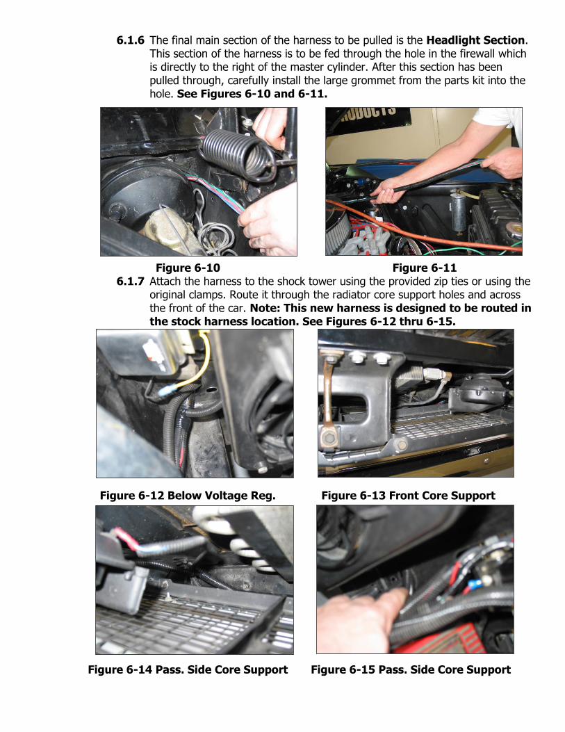
6.1.6 The final main section of the harness to be pulled is the Headlight Section. This section of the harness is to be fed through the hole in the firewall which is directly to the right of the master cylinder. After this section has been pulled through, carefully install the large grommet from the parts kit into the hole. See Figures 6-10 and 6-11.
Figure 6-10 Figure 6-11
6.1.7 Attach the harness to the shock tower using the provided zip ties or using the original clamps. Route it through the radiator core support holes and across the front of the car. Note: This new harness is designed to be routed in the stock harness location. See Figures 6-12 thru 6-15.
Figure 6-12 Below Voltage Reg. Figure 6-13 Front Core Support
Figure 6-14 Pass. Side Core Support Figure 6-15 Pass. Side Core Support

6.2 Harness Attachment
Harness routing and shaping is and should be a time-consuming task. Taking your time will enhance the beauty of your installation. Please be patient and TAKE YOUR TIME!
6.2.1 Mold the harness to contour the firewall, fenders, core support or any other areas where wires or harness sections are routed. Remember to route the harness away from sharp edges, exhaust pipes, hood, trunk, and door hinges.
6.2.2 Attach harness groups to your automobile with clips or zip ties starting at the fuse block and working you way towards the outer harness circuits. The dash wires should be routed out of the way of any under-dash obstacles, such as vent levers, air conditioning controls, radio, etc.
Note: Do not tighten tie wraps and mounting devices until each individual connection has been made on the particular circuit to be wire tied. Make all harness attachments LOOSELY, until all connections are made in each section.
6.2.3 When using wire loom on the visible areas of the harness, it will need to be wire tied every 12" or so. This will make a very attractive assembly. Under the dash a tie installed every 6" or so will hold the wires in place nicely. Remember to take your time.
6.3 Grounding the Automobile
This Painless Wire Harness Kit includes the following ground wires: two front lights ground harnesses, one tail ground harness, one built-in ground wire for the horn, one ground wire on the cluster harness and a ground wire for the accessory relay. Any additional circuits or accessories requiring a ground will have to be added.
6.3.1 Connect a Ground Strap or Cable (even a 10-gauge wire is too small) from the Negative Battery terminal to the automobile frame.
6.3.2 Connect a Ground Strap from the Engine to the frame. DO NOT RELY UPON THE MOTOR MOUNTS TO MAKE THIS CONNECTION.
6.3.3 Connect a Ground Strap from the Engine to the Body.
6.4 Terminal Installation and Making Connections
Note: In the following steps you will be making the circuit connections. Before you start, you should carefully read Sections 7.0, as appropriate, and refer to Section 8.0 as needed, DOUBLE-CHECKING your routing and length calculations before cutting any wires and making connections. The majority of the harness has been pre-terminated.
6.4.1 Have all needed tools and connectors handy. 6.4.2 Select the correct size terminal for the wire application. 6.4.3 Determine the correct wire length and cut the wire. Remember to allow
enough slack in the harness and wires at places where movement could possibly occur, such as automobile body to frame, frame to engine, etc. Double-check your calculations.

6.4.4 Strip the insulation from the wire. Strip only enough necessary for the type of terminal you are using. All of the terminals included in this kit require a ¼” strip length.
6.4.5 Insert the stripped portion of the wire into the crimp side of the terminal. Be careful as to not allow the individual wire strands to fray during insertion.
6.4.6 Crimp the terminal onto the wire using the proper jaw location on the crimpers.
Note: In step 6.4.6 be sure to use the proper jaw location on your crimpers. Most crimping tools have it color coded for which cavity to use. 18-22ga – Red, 16-14ga – Blue, and 12-10ga – Yellow. CAUTION: DO NOT OVER-CRIMP!
6.4.7 Many connections will be made throughout the installation process. Make sure each wire is FIRST properly routed and THEN attach. DO NOT ATTACH FIRST AND ROUTE AFTERWARD.
6.4.8 After all wires are terminated and securely attached, tighten the mounts and/or zip ties to secure the harness permanently.
6.5 Testing The System
6.5.1 Use a small (10 amp or less) battery charger to power up the vehicle for the first time to test the circuits. If there is a problem anywhere, the battery charger's low amperage and internal circuit breaker will provide circuit protection.
CAUTION: IF YOU HAVE NOT YET DISCONNECTED THE BATTERY FROM THE AUTOMOBILE, DO SO NOW! DO NOT CONNECT THE BATTERY CHARGER WITH THE BATTERY CONNECTED.
6.5.2 Connect the battery charger's NEGATIVE cable to the automobile chassis or engine block and its POSITIVE cable to the automobile's positive battery terminal lug.
6.5.3 INDIVIDUALLY turn on each light, ignition, wiper circuit, etc. and check for proper operation.
Note: The turn signals will not flash properly if you do not have both the front and rear bulbs installed and connected.
6.5.4 After all circuits have been checked, disconnect the battery charger and attach the vehicles battery cables to the battery. REPEAT STEP 6.5.3.

REGULATOR
AI FS
SWITCHIGNITION
STARTER SOLENOID
IS
ALTERNATOR
B+
FG
S
BATTERY
GROUND
GROUND
CHARGE
LIGHT
TO KEY "ON" BATTERY B+
BLK/GRN
YLW #913
WHT #970
BLK/RED #981
GRN/RED #915
BLK/YLW #971
WHT/BLK #972
* THIS WIRE WILL HAVE A LABEL AND IS NOT PRINTED.
*
INDICATOR
FUSE BLOCKFROM
BLK #916
BLK #916
MAXI FUSE
7.0 SPECIFIC CIRCUIT CONNECTIONS
7.1 Alternator/Regulator/Solenoid See Figure 7-1. 7.1.1 Connect HEADLIGHT SECTION wire #915 (Blk/Ylw) to the Alternator
Output post marked “Bat” or “B+”. See Figure 7-2 7.1.2 Connect HEADLIGHT SECTION wire #914 (Wht) to the Alternator post
marked “FLD”. See Figure 7-2 7.1.3 Locate the Voltage Regulator Connector in the HEADLIGHT SECTION and
plug it in to the Voltage Regulator, which is on the driver’s side engine compartment on the core support.
7.1.4 Connect the yellow wire with the preinstalled female bullet connector to the Noise Capacitor.
7.1.5 Locate the Maxi Fuse Base in the parts kit and attach it to the passenger side shock tower. See Figure 7-3
7.1.6 Connect HEADLIGHT SECTION wire #916 to one side of Maxi Fuse Base. Using the remaining portion of wire #916 connect the other side of the Maxi Fuse Base to the Battery side of the starter solenoid. See Figures 7-1, 7-3, & 7-4.
Figure 7-1 Alternator/Regulator/Solenoid Connections 7-2 Alternator Connections

Figure 7-3 R.H. Shock Tower Figure 7-4 Wire #916 Connection 7.2 High Amperage Alternator Kit
7.2.1 If an alternator with an output of more than 65 amps is being installed, a Painless High Amperage Alternator Kit, Painless P/N 30709, will need to be purchased.
7.3 Engine Section See Figure 7-5. 7.3.1 Connect ENGINE SECTION wire #920 to one side of the ballast resistor.
Connect the other side of the ballast resistor to the positive post on the ignition coil. Note: If using a ballast resistor be sure to mount it away from other wiring and hoses. It gets very hot during operation.
7.3.2 ENGINE SECTION wire #970 is used both on a point’s type ignition system and a Duraspark II System. It is to be connected directly to the positive post on the ignition coil or the coil feed side on the ballast resistor. The other end is to be connected to the “I” terminal on the starter solenoid. See Figure 7-5.
7.3.3 Connect ENGINE SECTION wire #919 to the “S” terminal on the starter solenoid. If using a Tachometer, connect ENGINE SECTION wire #923 to the negative side of the ignition coil. See Figure 7-5
Figure 7-5 Points Type Ignition Diagram
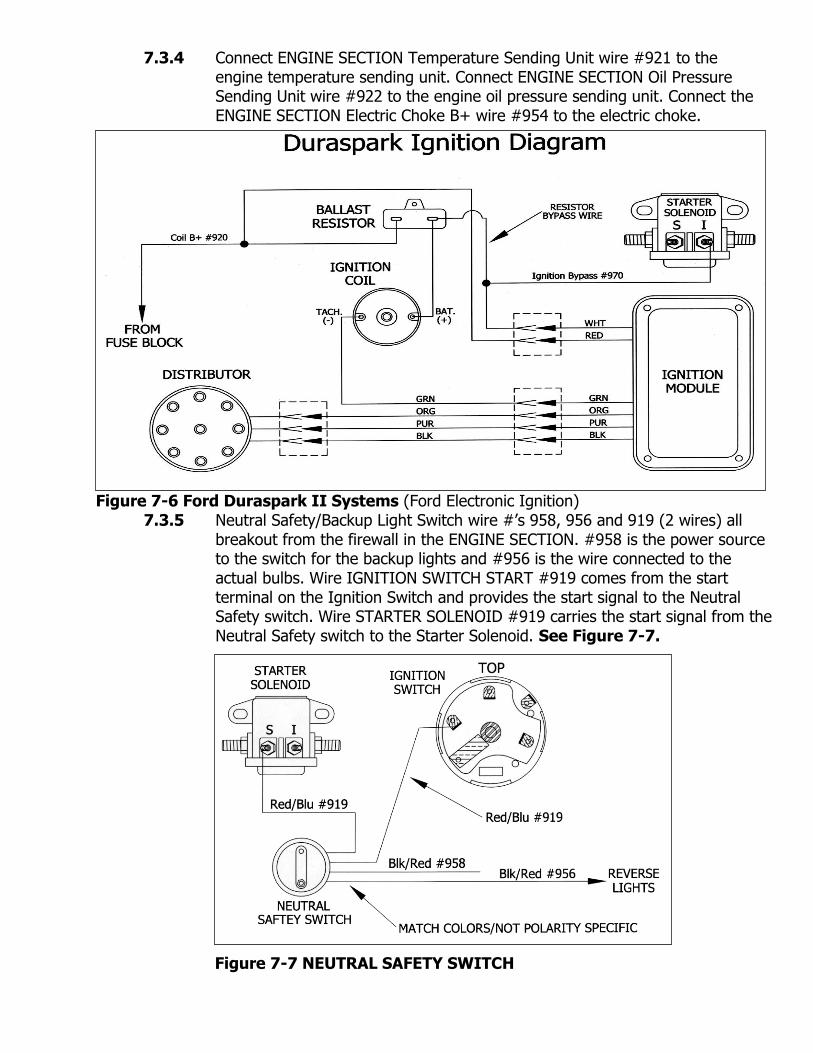
7.3.4 Connect ENGINE SECTION Temperature Sending Unit wire #921 to the engine temperature sending unit. Connect ENGINE SECTION Oil Pressure Sending Unit wire #922 to the engine oil pressure sending unit. Connect the ENGINE SECTION Electric Choke B+ wire #954 to the electric choke.
Figure 7-6 Ford Duraspark II Systems (Ford Electronic Ignition)
7.3.5 Neutral Safety/Backup Light Switch wire #’s 958, 956 and 919 (2 wires) all breakout from the firewall in the ENGINE SECTION. #958 is the power source to the switch for the backup lights and #956 is the wire connected to the actual bulbs. Wire IGNITION SWITCH START #919 comes from the start terminal on the Ignition Switch and provides the start signal to the Neutral Safety switch. Wire STARTER SOLENOID #919 carries the start signal from the Neutral Safety switch to the Starter Solenoid. See Figure 7-7.
Figure 7-7 NEUTRAL SAFETY SWITCH

7.4 Headlights/Front Turn Signals/Park Lights/Horns
Figure 7-8 Front Lights and Horns
7.4.1 Locate the pre-terminated Headlight Pigtails and the Front Lights Ground Harnesses in the parts kit. Install one of the Headlight Pigtails onto each headlight. Feed the wires from each pigtail through the body and core support down to the back of the turn signal housings in each wheel well.
7.4.2 *The Front Lights Ground Harness has one 14 gauge wire and two 18 gauge wires. One end of the 14 gauge wire is pre-terminated and will need to be connected to a body bolt. See Figure 7-9. The other end of the 14 gauge wire is for the headlights ground. The two 18 gauge wires are to be connected to the Turn/Park Lamps ground and to the Side Marker Lamps ground. See Figure 7-8.
Figure 7-9 Front Lights Ground Harness

Note: Some Mustangs had turn signal indicators on the hood. These lights are supported through this harness by connecting them to the #926 Left Turn Signal wire and the #925 Right Front Turn Signal wire. These wires are located just inside the vehicle past the main grommet on the firewall in the Headlight Section.
7.5 Rear Light Section
7.5.1 The REAR LIGHT SECTION consists of: Taillights, Stoplights, Left and Right Turn Signals, Trunk Light, Backup Lights, License Plate Light, and Fuel Sending Unit.
Figure 7-10 Rear Light Section and Dome Light
7.5.2 Locate and connect the Tail Ground Harness as shown in Figure 7-10. The wires in this section are to be routed in the same location as the stock harness. Use the metal tabs under the rear trunk opening lip to secure the harness.
See Figure 7-11.

Figure 7-11 Trunk Wiring Tabs 7.6 Steering Column Wiring-Turn Signal Connections
7.6.1 If wiring a 1967 Mustang the original Turn Signal Switch Connector will plug directly into the new Painless harness. The only additional connection to be made is to attach the pre-terminated Horn Switch Ground. See Figure 7-12.
7.6.2 If wiring a 1968 Mustang the original Turn Signal Switch Connector from the old harness will need to be re-used. Carefully remove the original wires, ONE WIRE AT A TIME, replacing them with the new wires in the 1968 Mustang Turn Signal Adaptor Pigtail. The pigtail colors match the original colors in the old harness. Use small pair of needle nose pliers or a flat screwdriver to remove the original terminals from the connector cavities. See Figure 7-12.
Figure 7-12 Turn Signal Connectors
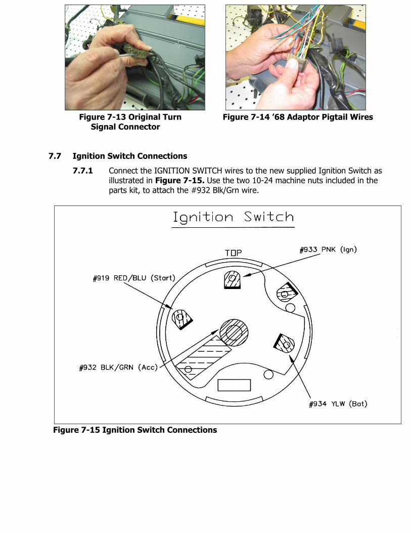
Figure 7-13 Original Turn Figure 7-14 ’68 Adaptor Pigtail Wires Signal Connector 7.7 Ignition Switch Connections
7.7.1 Connect the IGNITION SWITCH wires to the new supplied Ignition Switch as illustrated in Figure 7-15. Use the two 10-24 machine nuts included in the parts kit, to attach the #932 Blk/Grn wire.
Figure 7-15 Ignition Switch Connections

7.8 Headlight Switch
7.8.1 Connect the HEADLIGHT SWITCH wires as illustrated in Figure 7-16. After completing the installation of the Headlight Switch wires locate the DASH GROUND #969 wire, which is directly above the steering column in the main body of the harness and connect it to the chassis ground screw behind the gauge cluster.
Figure 7-16 Headlight Switch Connections
7.9 Brake Lights Switch
7.9.1 Route the BRAKE SWITCH wires #917 Brake Switch B+ (Grn/Red) and #918 Brake Switch Output (Grn) over the steering column and down to the Brake Switch located on the brake pedal. Leave enough slack in the wires to allow for the brake pedal movement. These wires are not polarity specific, in other words it does not matter which wires goes onto each side of the switch. See Figure 7-17.
Figure 7-17 Brake Switch
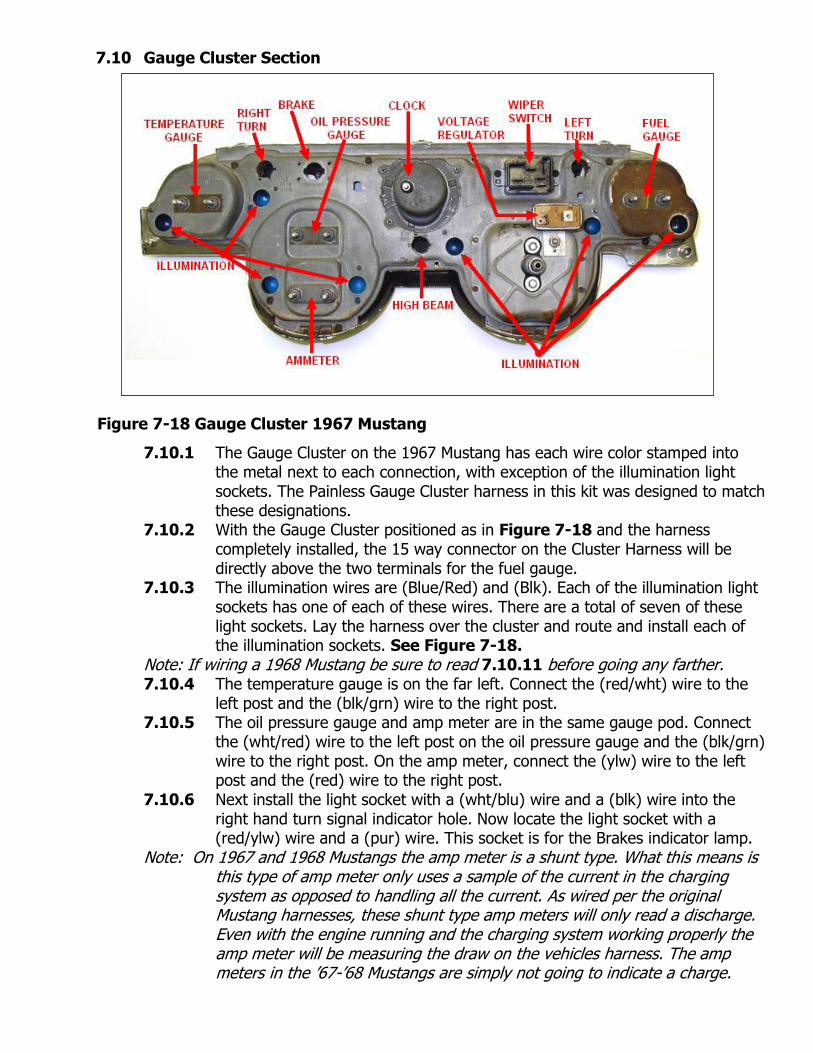
7.10 Gauge Cluster Section Figure 7-18 Gauge Cluster 1967 Mustang
7.10.1 The Gauge Cluster on the 1967 Mustang has each wire color stamped into the metal next to each connection, with exception of the illumination light sockets. The Painless Gauge Cluster harness in this kit was designed to match these designations.
7.10.2 With the Gauge Cluster positioned as in Figure 7-18 and the harness completely installed, the 15 way connector on the Cluster Harness will be directly above the two terminals for the fuel gauge.
7.10.3 The illumination wires are (Blue/Red) and (Blk). Each of the illumination light sockets has one of each of these wires. There are a total of seven of these light sockets. Lay the harness over the cluster and route and install each of the illumination sockets. See Figure 7-18.
Note: If wiring a 1968 Mustang be sure to read 7.10.11 before going any farther. 7.10.4 The temperature gauge is on the far left. Connect the (red/wht) wire to the
left post and the (blk/grn) wire to the right post. 7.10.5 The oil pressure gauge and amp meter are in the same gauge pod. Connect
the (wht/red) wire to the left post on the oil pressure gauge and the (blk/grn) wire to the right post. On the amp meter, connect the (ylw) wire to the left post and the (red) wire to the right post.
7.10.6 Next install the light socket with a (wht/blu) wire and a (blk) wire into the right hand turn signal indicator hole. Now locate the light socket with a (red/ylw) wire and a (pur) wire. This socket is for the Brakes indicator lamp.
Note: On 1967 and 1968 Mustangs the amp meter is a shunt type. What this means is this type of amp meter only uses a sample of the current in the charging system as opposed to handling all the current. As wired per the original Mustang harnesses, these shunt type amp meters will only read a discharge. Even with the engine running and the charging system working properly the amp meter will be measuring the draw on the vehicles harness. The amp meters in the ’67-’68 Mustangs are simply not going to indicate a charge.

NOTE: To check the Mustangs charging system, after the entire harness has been installed, connect a DC voltmeter across the battery with the engine running. A good charging system will measure between 13-14.5 volts. This voltage measurement can be affected by different sized pulleys and different engine idle rpms. This harness does not support the seat light. 7.10.7 If so equipped, the single (lt blu/blk) wire is to be connected to the back of
the clock. If a clock is not going to be connected, tape up and stow this wire with electrical tape.
7.10.8 Locate the socket with a (lt grn/blk) wire and a (blk) wire and install it into the high beam indicator hole.
7.10.9 Remove the Voltage Regulator mounting nut and install the single black wire with the ring terminal. Next locate the male spade terminal crimped on the end of two (blk/grn) wires and connect it to the left terminal on the voltage regulator. The female spade terminal with one (blk/grn) wire goes onto the right terminal of the voltage regulator.
7.10.10 Next install the light socket with a (grn/wht) wire and a (blk) wire into the left hand turn signal indicator hole. The last two wires are for the Fuel Gauge. The (ylw/wht) goes onto the left post and the (blk/grn) on the right post. This completes the Gauge Cluster Section.
7.10.11 The difference between a 1967 Mustang Gauge Cluster vs. a 1968 Mustang Gauge Cluster is the location of the Fuel Gauge and the Oil Pressure Gauge. These two gauges are in the opposite location on a 1968 as compared to a 1967. Because of this the two wires that will be different are the (wht/red) and the (ylw/wht). Be sure to install the (wht/red) on the Oil Pressure Gauge left hand post and the (ylw/wht) on the Fuel Gauge left hand post.
7.11 Heater-A/C Components
Figure 7-19 Blower Motor/Blower Motor Resistor/Blower Motor Switch
7.11.1 The connections for the Blower Motor, Blower Motor Resistor and Blower Motor Switch in a Mustang with a Heater ONLY are illustrated in Figure 7-19. The ground for the Blower Motor Switch is internal to the switch, meaning there are no connections to be made. The wire colors on wire numbers 973, 974, & 975 all match the wire colors coming out of the switch. The wire #976 (ylw) connects to the Orange wire on the blower motor. The wire #967 (brn) connects to the Black wire on the blower motor.

7.11.2 On all Mustangs equipped with add-on or factory Air Conditioning the included A/C Harness must be installed. See Figure 7-20.
Figure 7-20 Heater with Air Conditioning
7.11.3 Figure 7-20 has both the Air Conditioning control harness and the Blower Motor wiring. Be sure to read the wire identification on each wire and connect the wires to the correct components.
7.12 Wiper Switch/Coordination Switch/Dimmer Switch/Wiper Motor Figure 7-21 Wiper Switch Connections

Figure 7-22 Coordination Switch
7.12.1 The connections for the Wiper Switch in the cluster are illustrated in Figure 7-21.
7.12.2 The connections for the Coordination Switch on the floor near the drivers kick panel are illustrated in Figure 7-22. The Coordination Switch wires and the Headlight Dimmer Switch wires are bundled together. After connecting the Coordination Switch wires, connect the following for the Dimmer Switch: Dimmer Switch B+ #907 to the center spade terminal, Dimmer Switch (Low Beams) #909 and Dimmer Switch (High Beams) #908 each to one of the outside spade terminals.
Figure 7-23 Wiper Motor Plug

7.12.3 The connections for the Wiper Motor are illustrated in Figure 7-23. Be sure to note the cavities for wire #979 and #977 are female and for #985 and #982 are male bullets.
7.13 Interior Lighting and Accessories 7.13.1 The interior lighting circuit is activated by three different switches. One switch
is located inside the headlight switch and the other two are located in each door jamb. The door jamb wires for each switch are pre-terminated and will plug directly into the 1967 style Mustang door jamb switches. The switches on the 1968 Mustang use a different style terminal and will require splicing onto the original switch connectors. One #987 and one #988 wire connect to each of the door jamb switches. All are marked for which door jamb switch they connect to and are not polarity specific.
7.13.2 The interior lights supported by this harness include: both Left and Right Hand Courtesy Lights (#989) under the dash, Dome Light (#945), Trunk Light (#946), and if so equipped both “B” pillar lights. The “B” pillar lights are located in the interior panels behind the driver and passenger front seats. To power these, use the splice on each of the door jamb switches #988 wires.
7.13.3 The Glove Box Light Switch B+ #990 connects to the glove box light. Cigar Lighter B+ #903 connects directly to the Cigar lighter power terminal.
7.13.4 The Console Light B+ #930, Radio Light B+ #930, the Tachometer Light B+ #930, and the Gauge Cluster Illumination Lights are all controlled by the Headlight Switch dimmer circuit when the Headlights or Park lights are ON. Each wire description dictates the component to connect them to.
7.13.5 Constant Radio B+ #940 is to be connected to the Memory or Constant input on an aftermarket stereo. (Most CD players with a clock require this input) The Switched Radio B+ #941 is another wire required on most stereos.
7.13.6 If a Tachometer is to be installed use wires: Tachometer B+ #966, Tachometer Signal #923 and the Tachometer Light B+ #930 wire described in step 7.13.4.
7.13.7 The final Accessory component in this Mustang chassis harness is a 20amp accessory relay output. The relay is preinstalled in the fuse block, powered, and fused. See Figure 7-24.
Figure 7-24 Accessory Relay Diagram

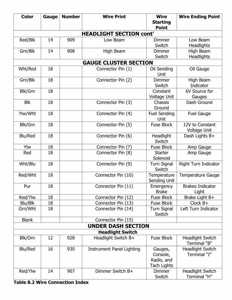
8.0 WIRE CONNECTION INDEX AND FUSE REQUIREMENTS
8.1 Wire Connection Index
In each section, connect the wire, as identified by its wire color, to the appropriate item in the Wire Ending Point column.
Table 8.2 is divided into sections that correspond to the sections of your wire harness. (ENGINE SECTION, HEADLIGHT SECTION, GAUGE CLUSTER SECTION, UNDER DASH SECTION, INTERIOR LIGHTING SECTION, AND REAR LIGHT SECTION) The index is divided vertically into six columns. COLOR, GAUGE, NUMBER, WIRE PRINT, WIRE STARTING POINT, and WIRE ENDING POINT.
The information in these columns are for reference to help identify where each wire and what it needs to be connected to. These columns tell where each wire originates, the wire number, its function and which section of the harness the wire is in.
The column labeled NO. contains a 900-series number used to identify the wires in the diagrams in Section 6.0 and 7.0 of this manual.
The wire numbers which occur TWICE in this index indicate the connection of BOTH ENDS or a splice of wires inside the harness. Most wire segments are pre-connected at the WIRE STARTING POINT such as all the wires originating from the fuse panel. The WIRE ENDING POINT is where that wire needs to be connected.
Table 8.1 Fuse Requirements
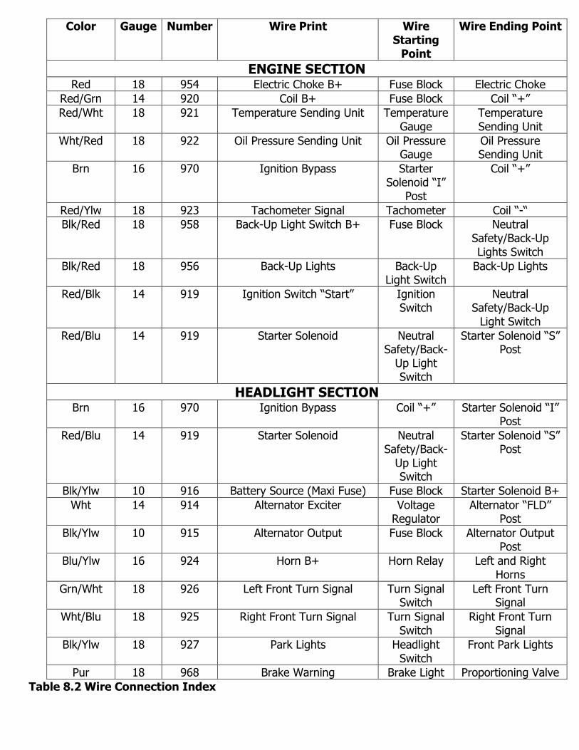
Table 8.2 Wire Connection Index
Color Gauge Number Wire Print Wire Starting
Point
Wire Ending Point
ENGINE SECTION Red 18 954 Electric Choke B+ Fuse Block Electric Choke
Red/Grn 14 920 Coil B+ Fuse Block Coil “+”
Red/Wht 18 921 Temperature Sending Unit Temperature Gauge
Temperature Sending Unit
Wht/Red 18 922 Oil Pressure Sending Unit Oil Pressure Gauge
Oil Pressure Sending Unit
Brn 16 970 Ignition Bypass Starter Solenoid “I”
Post
Coil “+”
Red/Ylw 18 923 Tachometer Signal Tachometer Coil “-“
Blk/Red 18 958 Back-Up Light Switch B+ Fuse Block Neutral Safety/Back-Up Lights Switch
Blk/Red 18 956 Back-Up Lights Back-Up Light Switch
Back-Up Lights
Red/Blk 14 919 Ignition Switch “Start” Ignition Switch
Neutral Safety/Back-Up
Light Switch
Red/Blu 14 919 Starter Solenoid Neutral Safety/Back-
Up Light Switch
Starter Solenoid “S” Post
HEADLIGHT SECTION Brn 16 970 Ignition Bypass Coil “+” Starter Solenoid “I”
Post
Red/Blu 14 919 Starter Solenoid Neutral Safety/Back-
Up Light Switch
Starter Solenoid “S” Post
Blk/Ylw 10 916 Battery Source (Maxi Fuse) Fuse Block Starter Solenoid B+
Wht 14 914 Alternator Exciter Voltage Regulator
Alternator “FLD” Post
Blk/Ylw 10 915 Alternator Output Fuse Block Alternator Output Post
Blu/Ylw 16 924 Horn B+ Horn Relay Left and Right Horns
Grn/Wht 18 926 Left Front Turn Signal Turn Signal Switch
Left Front Turn Signal
Wht/Blu 18 925 Right Front Turn Signal Turn Signal Switch
Right Front Turn Signal
Blk/Ylw 18 927 Park Lights Headlight Switch
Front Park Lights
Pur 18 968 Brake Warning Brake Light Proportioning Valve
Color Gauge Number Wire Print Wire Starting
Point
Wire Ending Point
HEADLIGHT SECTION cont’ Red/Blk 14 909 Low Beam Dimmer
Switch Low Beam Headlights
Grn/Blk 14 908 High Beam Dimmer Switch
High Beam Headlights
GAUGE CLUSTER SECTION Wht/Red 18 Connector Pin (1) Oil Sending
Unit Oil Gauge
Grn/Blk 18 Connector Pin (2) Dimmer Switch
High Beam Indicator
Blk/Grn 18 Constant Voltage Unit
6V Source for Gauges
Blk 18 Connector Pin (3) Chassis Ground
Dash Ground
Ylw/Wht 18 Connector Pin (4) Fuel Sending Unit
Fuel Gauge
Blk/Grn 18 Connector Pin (5) Fuse Block 12V to Constant Voltage Unit
Blu/Red 18 Connector Pin (6) Headlight Switch
Dash Lights B+
Ylw 18 Connector Pin (7) Fuse Block Amp Gauge
Red 18 Connector Pin (8) Starter Solenoid
Amp Gauge
Wht/Blu 18 Connector Pin (9) Turn Signal Switch
Right Turn Indicator
Red/Wht 18 Connector Pin (10) Temperature Sending Unit
Temperature Gauge
Pur 18 Connector Pin (11) Emergency Brake
Brakes Indicator Light
Red/Ylw 18 Connector Pin (12) Fuse Block Brake Light B+
Blu/Blk 18 Connector Pin (13) Fuse Block Clock B+
Grn/Wht 18 Connector Pin (14) Turn Signal Switch
Left Turn Indicator
Blank Connector Pin (15)
UNDER DASH SECTION
Headlight Switch
Blk/Orn 12 928 Headlight Switch B+ Fuse Block Headlight Switch Terminal “B"
Blu/Red 16 930 Instrument Panel Lighting Gauges, Console,
Radio, and Tach Lights
Headlight Switch Terminal “I”
Red/Ylw 14 907 Dimmer Switch B+ Dimmer Switch
Headlight Switch Terminal “H”
Table 8.2 Wire Connection Index

Color Gauge Number Wire Print Wire Starting
Point
Wire Ending Point
UNDER DASH SECTION Con’t
Headlight Switch Cont’
Blk/Ylw 16 927 Park Lights Park Lights Headlight Switch Terminal “P”
Blk 14 929 Tail Lights Tail Lights Headlight Switch Terminal “R”
Grn/Ylw 18 971 Dome B+ to Headlight Switch (D1)
Fuse Block Headlight Switch Terminal (D1)
Blk/Blu 18 971 Dome B+ to Headlight Switch (D2)
Dome and Trunk Lights
Headlight Switch Terminal (D2)
Ignition Switch Connections
Ylw 12 934 Ignition Switch B+ Maxi Fuse Ignition Switch
Blk/Grn 14 932 Ignition Switch Accessory Fuse Block Ignition Switch
Pnk 12 933 Ignition Switched Ignition Fuse Block Ignition Switch
Red/Blk 14 919 Starter Solenoid Neutral Safety/Back-
Up Light Switch
Ignition Switch
Turn Signal Switch
Grn/Orn 14 949 Left Rear Turn Signal Left Rear Turn/Stop
Light
Turn Signal Switch
Wht/Red 16 951 Emergency Flasher Switch B+ Emergency Flasher
Turn Signal Switch
Blu 14 952 Turn Signal Flasher Switch B+
Turn Signal Flasher
Turn Signal Switch
Grn 14 918 Brake Switch Output Brake Switch Turn Signal Switch
Grn/Wht 18 926 Left Front Turn Signal Left Front Turn Signal
Turn Signal Switch
Wht/Blu 18 925 Right Front Turn Signal Right Front Turn Signal
Turn Signal Switch
Orn/Blk 14 948 Right Rear Turn Signal Right Rear Turn/Stop
Light
Turn Signal Switch
Blk 18 963 To Horn Switch Horn Relay Turn Signal Switch
Blk 18 963 Horn Switch Ground Chassis Ground
Turn Signal Switch
Grn/Wht 18 Left Hood Turn Signal Indicator (Optional)
Left Hood Turn
Indicator
Turn Signal Switch
Wht/Blu 18 Right Hood Turn Signal Indicator (Optional)
Right Hood Turn
Indicator
Turn Signal Switch
Table 8.2 Wire Connection Index

Color Gauge Number Wire Print Wire Starting
Point
Wire Ending Point
UNDER DASH SECTION Con’t
Wiper Switch
Orn/Wht 16 905 Wiper Motor B+ Fuse Block Wiper Motor
Blu 16 977 To Wiper Switch/To Wiper Motor
Wiper Motor Wiper Switch
Wht 16 978 To Wiper Switch (Low) Coordination Switch/Wiper
Motor
Wiper Switch
Red 16 981 Wiper Park/Washer Coordination Switch/Wiper
Motor
Wiper Switch
Blk 16 984 To Coordination Switch/To Wiper Switch
Coordination Switch
Wiper Switch
Wiper Coordination Switch
Wht 16 980 Coordination Switch (Low) Wiper Motor/Wiper
Switch
Coordination Switch
Red 16 983 Washer Wiper Motor/Wiper
Switch
Coordination Switch
Blk 16 984 To Coordination Switch/To Wiper Switch
Wiper Switch Coordination Switch
Blk 16 985 To Wiper Motor/To Coordination Switch
Wiper Motor Coordination Switch
Wiper Motor
Blu 16 977 To Wiper Switch/To Wiper Motor
Wiper Switch Wiper Motor
Wht 16 979 To Wiper Motor (Low) Wiper Switch Wiper Motor
Red 16 982 Wiper Motor Coordination Switch/Wiper
Switch
Wiper Motor
Blk 16 985 To Wiper Motor/To Coordination Switch
Coordination Switch
Wiper Motor
Brake Switch
Grn/Red 14 917 Brake Switch B+ Fuse Block Brake Switch
Grn 14 918 Brake Switch Output Turn Signal Switch
Brake Switch
Dimmer Switch
Grn/Blk 14 908 Dimmer Switch (High Beam) High Beams Dimmer Switch
Red/Blk 14 909 Dimmer Switch (Low Beam) Low Beams Dimmer Switch
Red/Ylw 14 907 Dimmer Switch B+ Headlight Switch
Dimmer Switch “Center Spade”
Table 8.2 Wire Connection Index

Color Gauge Number Wire Print Wire Starting
Point
Wire Ending Point
UNDER DASH SECTION Con’t
Be sure to follow Figure 7-19 for Heater only and Figure 7-20 for Heater and A/C.
Blower Motor
Brn 14 967 Blower Motor B+ Fuse Block Blower Motor
Ylw 14 976 To Blower Motor/To Blower Motor Resistor
Blower Motor
Resistor
Blower Motor
Heat-A/C Blower Motor Resistor
Blk/Ylw 14 973 Blower Motor (High) Heat-A/C Switch
Blower Motor Resistor
Blu 14 974 Blower Motor (Med) Heat-A/C Switch
Blower Motor Resistor
Red 14 975 Blower Motor (Low) Heat-A/C Switch
Blower Motor Resistor
Ylw 14 976 To Blower Motor Resistor/To Blower Motor
Blower Motor
Blower Motor Resistor
Blower Motor Switch
Blk/Ylw 14 973 Blower Motor (High) Blower Resistor Block
Blower Motor Switch
Blu 14 974 Blower Motor (Med) Blower Resistor Block
Blower Motor Switch
Red 14 975 Blower Motor (Low) Blower Resistor Block
Blower Motor Switch
Under-Dash Section Accessories
Blk/Wht 14 903 Cigar Lighter B+ Fuse Block Cigar Lighter
Blu/Red 18 930 Tachometer Light B+ Headlight Switch
Tachometer Light
Red 18 966 Tachometer B+ Fuse Block Tachometer Power
Red/Ylw 18 923 Tachometer Signal Engine Section
Tachometer Signal
Orn 16 991 Accessory Relay Power Output (20 Amp Max)
Accessory Relay
20 Amp or less Accessory
Blk 18 992 Accessory Relay Activation Ground
Accessory Relay
Ground Activation Switch
Blu/Red 18 930 Radio Light B+ Headlight Switch
Light in Radio
Red 18 940 Constant Radio B+ Fuse Block Radio
Ylw/Blk 18 941 Switched Radio B+ Fuse Block Radio
Pur 18 968 Brake Warning Brake Light Emergency Brake Switch
Table 8.2 Wire Connection Index

Color Gauge Number Wire Print Wire Starting
Point
Wire Ending Point
INTERIOR LIGHTING SECTION
Grn/Ylw 18 988 To Right Door Jamb Switch B+
Fuse Block Right Door Jamb Switch
Blk/Blu 18 988 To Right Door Jamb Switch Interior Lighting Circuit
Right Door Jamb Switch
Blk/Blu 18 989 Right Courtesy Light Right Door Jamb Switch
Right Courtesy Light
Grn/Ylw 18 987 To Left Door Jamb Switch B+ Fuse Block Left Door Jamb Switch
Blk/Blu 18 987 To Left Door Jamb Switch Interior Lighting Circuit
Left Door Jamb Switch
Blk/Blu 18 989 Left Courtesy Light Left Door Jamb Switch
Left Courtesy Light
Grn/Ylw 18 990 To Glove Box B+ Fuse Block Glove Box Light Switch
Blu/Red 18 930 Center Console Light B+ Headlight Switch
Center Console Light
REAR LIGHT SECTION Blk/Blu 18 945 To Dome Light Headlight
Switch/Jamb Switches
Dome Light
Blk/Red 18 956 Back-Up Lights Back-Up Light Switch
Back-Up Lights
Grn/Orn 14 949 Left Rear Turn Signal Turn Signal Switch
Left Rear Turn/Stop Signal
Orn/Blu 14 948 Right Rear Turn Signal Turn Signal Switch
Right Rear Turn/Stop Signal
Ylw/Wht 18 939 Fuel Sending Unit Fuel Gauge Fuel Sending Unit
Blk 16 929 Tail Lights Headlight Switch
Tail Lights
Blk 18 962 License Plate Light B+ Headlight Switch
License Plate Light
Grn/Ylw 18 946 Trunk Light B+ Headlight Switch
Trunk Light
Table 8.2 Wire Connection Index