winter 1999-’00 the kawasakitechnical...
TRANSCRIPT
W I N T E R 1 9 9 9 - ’ 0 0 T H E K AWA S A K I T E C H N I C A L M A G A Z I N E V O L . 1 2 , N O . 4
ROUTE LIST ❑ SERVICE ❑ PARTS ❑ SALESP L E A S E R E T U R N T O S E R V I C E L I B R A R Y
INSIDEFeature 1100 STX D.I. . . . . . . . . . . . . 2Regional Update . . . . . . . . . . . . . . . . . 4News Tool Corner . . . . . . . . . . . . . . 5
CD Sales Guides . . . . . . . . . . . 5Service Bulletins . . . . . . . . . . . 5
Tech Tips KX Bladder-Type Fork . . . . . . . 6Shipping Costs . . . . . . . . . . . . 7VN800 Valve Correction . . . . . 7KX125 Jetting Kit . . . . . . . . . . 7Ultra 150 Choke. . . . . . . . . . . 8Consumer Calls. . . . . . . . . . . . 8Bayou 220 Carb . . . . . . . . . . . 9Mule Tidbits . . . . . . . . . . . . . . 9Diesel Fuel Injection . . . . . . . 10Overheated Exhaust . . . . . . . 10KSF250 Kickstarter Gear . . . . 11
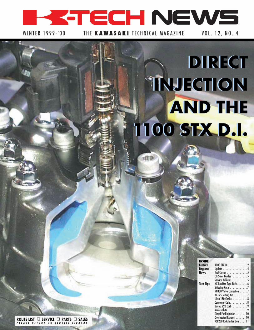
DIRECTINJECTION
AND THE1100 STX D.I.
DIRECTINJECTION
AND THE1100 STX D.I.

by John GriffinInstructionalDesigner/Instructor
The FICHT® DirectInjection on the new 1100STX D.I. is the mostsophisticated inductionsystem ever used on a JetSki® Watercraft. A braincalled the Engine Manage-ment Module (EMM) con-trols unique fuel injectorsto spray a precise amountof fuel directly into thecombustion chamber forunmatched throttleresponse and acceleration.Most of the fuel issprayed into the cylinderafter the exhaust port isclosed by the piston, so
there is little waste. It usesabout 30% less fuel andnearly 50% less oil forabout a 60% reduction inemissions.
The EngineThe engine has many
similarities with the 1100STX because the FICHT®system does not requireradical changes to the bot-tom-end or cylinders. Themain change below thecylinder head is that thecrankshaft now uses adouble row bearingbetween the #1 cylinderand a new high outputstator assembly.
The double row bear-ing is lubricated directly
by the oil pump with anew (fourth) oil line con-necting to the cases. Theother bearings, connectingrods, cylinders, and pis-tons are lubricated in amore traditional manner.
Oil is pumped from thevariable output pumpinto each intake where itis picked up by the airstream between the throt-tle plates and new six-petal reed valves. Becausethere is no fuel to dilutethe oil, much less isrequired.
The top-end of theengine is all new. Thecylinder head has newbell-shaped combustion
WINTER 1999-’00 K-TECH NEWS
Cover Story
2
Direct Injection and the new 1100 STX D.I.
Lubrication is handledby oil pumped throughnozzles into the airstream and by an extraoil line pumping oil intothe cases for a new dou-ble row #1 main bear-ing.
An all-new hull softens the ride by reducing wave shock, while new sponsonsimprove cornering. A revised jet pump and more powerful engine boost thrustto 851lb. ft. for a craft that is 8 mph faster and has quicker acceleration. Stor-age is nearly doubled to 23.5 gallons, with a new tub under the front hood.
Ficht engine with sensor layout (Usesensor.ppt with arrows & letters orsensor.jpg and K&D can add theirown.)No caption
Intake systemwith oil pipe(jt1100int.jpg)
chambers with access forone high-pressure injectoron the top and oneextended nose spark plug(NGK PZFR7G-G) in theside for each cylinder. Thepistons have a "splashport" dish formed in thecrown to help atomize thefuel spray in the homoge-neous mode (more on thislater).
The InjectorsThe EMM powers an
electromagnet in the injec-tors with 45 Volts to blastfuel into the cylinder atpressures over 250 psi, upto 150 times per second.The electromagnet movesan armature, which actslike a high-speed pistonpressurizing the fuel inthe nozzle end of theinjector. When this fuelpressure exceeds the noz-
zle’s poppet valve springpressure, it sprays fuelinto the combustionchamber. It takes highpressure to overcome nor-mal engine compressionin the combustion cham-ber. Since the injector pro-duces the high pressure, astandard fuel pump andfuel lines are used at aregulated 25 psi.
Each injector is flowtested for fuel output.These flow rates are pro-grammed into the EMMmap data to achieve nearidentical output in eachcylinder for optimumcombustion. Each injectoris marked with a serialnumber and the numbercylinder it is installed in.Make sure you keep theinjectors with the correctcylinder. To replace aninjector, you must use acomputer linked to theEMM to tell it that youhave installed a "replace-
ment" injector. Thischanges the injection pro-gram map for that cylin-der to a special defaultsetting. To replace theEMM, you must use theservice utilities function inthe diagnostic software totransfer data from the oldEMM and program it intothe replacement. This maysound complicated, but isa simple procedure.
Engine ManagementModule (EMM)
The EMM is more thanjust the brain of this boat.It also contains the regula-tor/ rectifier for a 12-Voltsystem used for the bat-tery and gauges, as wellas a 45-Volt system for theinjectors and ignition sys-tem. Water from theengine cooling systemflows through the EMM’swater jacket to fight heat
3WINTER 1999-’00 K-TECH NEWS
Cover Story
K-TECH NewsVol. 12, No.4
Winter 1999-’00
K-TECH News Staff
PublisherKawasaki Tech Services
Publications ManagerDon Church
Executive EditorGary Herzog
Editor-in-ChiefGregg Thompson
Communications EditorJohn Griffin
Regional EditorsPiscataway/Grand Rapids
Fred DeHart
Atlanta/TulsaWalter Rainwater
Irvine/TacomaRobert Taylor
ContributorsDavid Behlings, Alex Dell, Rick Rod-
dewig, Ray St. John, Charles Yim
Graphics/Production
Graphic ArtGregg Thompson
PhotographyJohn Griffin
ProductionHolland Marketing Services
©2000 Kawasaki Motors Corp., U.S.A.All rights reserved.
Published by Kawasaki
All suggestions become the property ofKMC. Sending a service suggestion givesKawasaki permission to publish and/or
use it without further consideration.Specifications subject to change without notice.
Continued on pg. 12
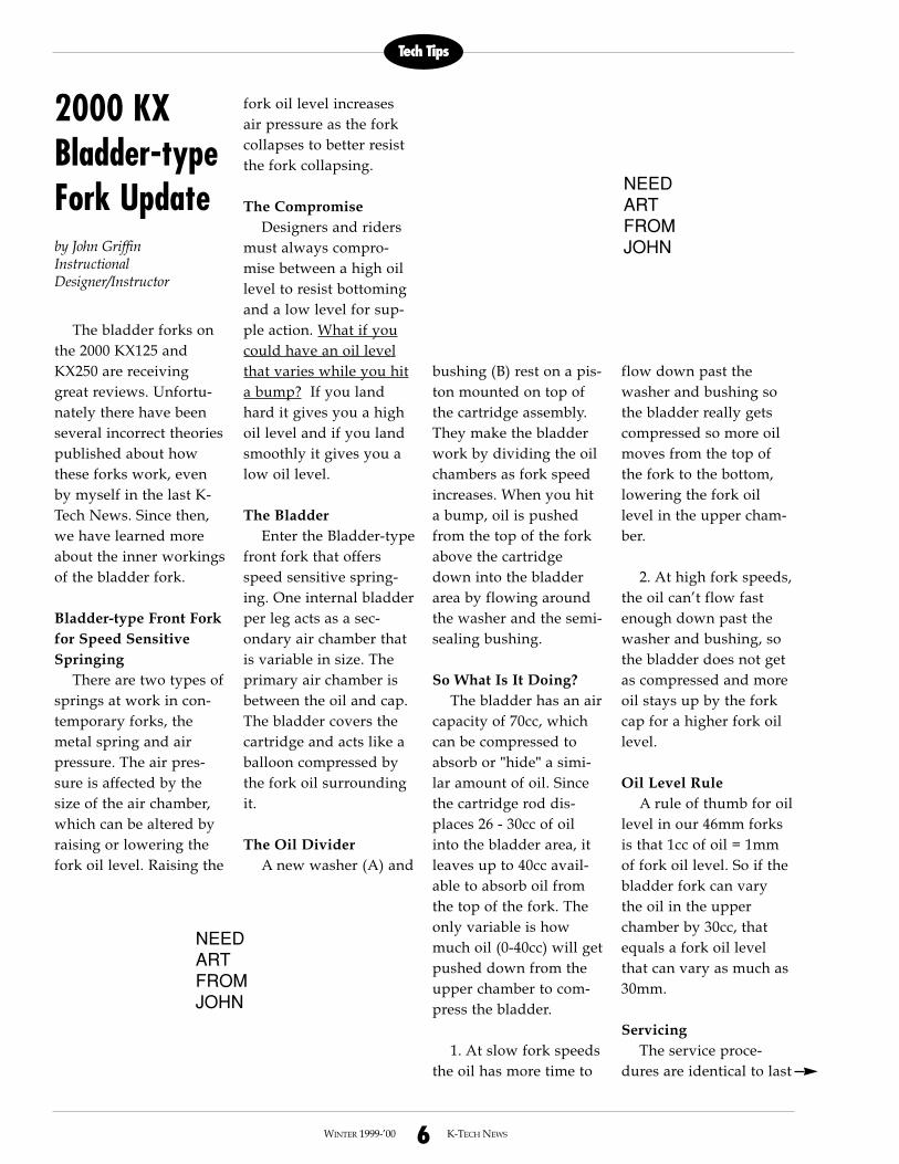
Stratified combustion isused below 5500 RPM.Fuel is ignited just afterit leaves the injectorwith the spark plug fir-ing as many as 15 timesto burn fuel more com-pletely.
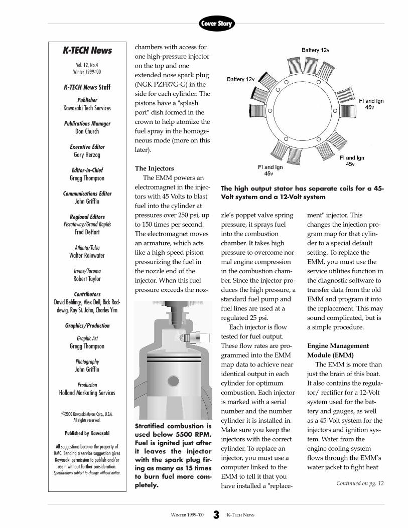
The high output stator has separate coils for a 45-Volt system and a 12-Volt system

4WINTER 1999-’00 K-TECH NEWS
Regional
DIESEL MULE NOTES
Note #1If you plan to check
engine compression on aDiesel Mule keep this inmind. You will need theunique compressiongauge adapter (57001-1431) and a compressiongauge that has a range upto 1,000 psi. Make sureyou find the fused brownwire under the seat andremove the fuse beforeyou turn the engine over.If you don’t, the enginecan start while you arechecking compression.
Note #2The Diesel Mule valve
guides are replaceablewith an oversize guide.When installing a newvalve guide, DO NOThammer the guide intothe head using the driver.The guides are pre-sizedand have a slightly largerID than the final specifica-tion. When installed in thehead, the interference fitwill put the guide intoproper specification.Install the guide into thehead using the guide dri-ver and a PRESS. Ham-mering the guide intoplace with the drivercould distort the guide
making it unusable sincethere is no reamer avail-able.�
Rob Taylor9950 Jeronimo Road
Irvine, CA 92618(949) 770-0400
CAN YOU KIC?While recently con-
ducting the 2000 ServiceUpdate Seminars, Ilearned there was a largepercentage of attendeesthat have still never usedKIC. They don’t realizehow valuable a tool KICis, and have not learned touse it.
KIC (Kawasaki Informa-tion Center) is part of K-Share and is sent to K-Share dealers on a CD-ROM with updates everytwo months. KIC has allof the parts informationlike a “microfiche on CD,”but it offers much more.KIC has all of the flat rateinformation, service bul-letins, and even sales liter-ature. There is so muchinformation available withjust a few clicks of amouse button!
K-Share is full of fea-tures to help dealers con-duct business withKawasaki. Kawasaki con-tinually adds new features
like the latest, ElectronicDocument Distribution(EDD). To keep you andall your employees up todate on K-Share and KIC,we are offering a one-daytraining class at our train-ing centers. The course isgreat for new and experi-enced users. Please referto the 2000 TrainingSchedule for the classdates nearest you and reg-ister early.
K-Share/KIC is a valu-able business tool. Use itto its fullest extent.
Walter Rainwater6110 Boat Rock Blvd. S.W.
Atlanta, GA 30378(404) 349-2000
POWER PARTNER 6000 LOW OIL LEVEL SENSOR
On some Power Part-ner 6000 Generators, thelow oil level sensor causesthe engine to not start, orquit, even if the oil level iscorrect. This could happenall the time, occasionally,or just in cold weather.Disconnecting the leadwire to the switch willallow the engine to startand run continuously. Besure to confirm the unit isat the proper oil levelbefore disconnecting the
sensor switch lead wire!If you encounter this
problem, the KawasakiSmall Engine Divisiondeveloped a kit (P/N99916-2152) to fix it. Thekit consists of a new oillevel sensor, switchbracket, and a spacer thatbetter positions the sensorin the crankcase. Theseparts are pre-assembledand can be bolted directlyin place of the old parts.
Power Partner 6000engines above # 57823should have the new partsinstalled from the factory.
If you install the oillevel sensor kit parts, it’srecommended that youalso install a new ignitioncontroller (P/N 21177-2064) with a third wirelead. The third wire is anexternal ground thatshould be bolted to theengine along with theignition ground wire. Theold controller could burnout the reed switch con-tacts in the oil level sensordue to high current levelswhen the switch shuts offthe ignition in a low oillevel situation.
If you have any prob-lems obtaining theseparts, contact Mr. JerryHooker at the KawasakiGrand Rapids PartsDepartment, 616-949-6500.
Fred DeHart201 Circle Drive N. #107
Piscataway, NJ 08854(732) 469-1221�
PISCATAWAY/GRAND RAPIDS
ATLANTA/TULSA
IRVINE/TACOMA

5WINTER 1999-’00 K-TECH NEWS
News
2000 Product Sales Guides on CD
Kawasaki has distributed a CD-ROM containing the new ProductSales Guides and Quick Reference Guide again this year. Even thoughyour store received one CD, you can order additional copies for only$10.00 each. These publications have detailed information on every2000 model and the valuable KAW-PEDIA. The "Tech Features"sheets towards the back of each book are full of technical highlights.The Quick Reference Guide contains specifications in a format thatsimplifies model comparisons. Contact us at (949) 770-0400 ext. 2463 to order extra CDs.
Note: this CD contains Adobe Acrobat Reader 4.0 which is used to view the documents and search forinformation. This CD will run with the 3.0 version, if you already have that installed on your PC.�–Don Church, Manager, Service Training and Communications
Mule 2510 Diesel
There are nine tools needed toservice the diesel engine and they areall now in stock. These tools areshown in the Service Manual startingon page 1-17. All other drive train andchassis tools are the same as the2510 gas model. The first new tool isa dial gauge adapter (57001-1430)which is used with a dial gauge yousupply to check the fuel pump adjust-ment. This adjustment is critical sinceit controls injection timing.
2000 ZX-6R, ZX-9R, and ZX-12R
These models share a new typeof steering head bearings. Instead oftapered roller bearings, they use ballbearings held in races that require anew procedure to install or adjustthem. You will need two new headpipe driver tools (57001-1446 and57001-1447). Check the A&P sheetsfor new higher torque values for thesteering stem locknut and head nut.
The ’00 ZX-9R has a new enginemounting system requiring a specialwrench (57001-1450) to adjust theframe-to-engine clearance duringinstallation. There is also a newadapter (57001-1448) needed tomeasure charging output voltage witha multimeter. To measure the primarypeak voltage of a stick-type ignitioncoil, use adapter 57001-1449.
To disassemble ’00 ZX-12R frontforks, hold the fork cylinder with anew holder (57001-1443) whileremoving the allen bolt on the bottomof the fork. A new fork spring com-pressor (57001-1452) is required tocompress the fork to loosen the pushrod nut. The procedure is almostimpossible without the spring compres-sor set. The last special tool (57001-1445) aligns the scissor-type primarygear on the clutch housing for installa-tion.�—Rob Taylor
CornerTool
by Don ChurchManager, Service Trainingand Communications
Kawasaki has recentlyissued some importantservice bulletins. Reac-quaint yourself with thesebulletins now. It is likelythat many customers willwait until spring to havethese repairs made sincetheir machines are cur-rently in storage.
Make this a policy inyour service department:use the K-Share VehicleService Inquiry (VSI) tocheck the warranty his-tory of every Kawasakiyou take in for service.VSI will show you if aunit is eligible for a Recallor Factory Directed Modi-fication (FDM). Plus, itwill show you if a claimhas already been submit-ted for the repair.�
Jet Ski Watercraft
Bulletin Number Subject Model
JS 99-03 Steering Cable JH1200-A1
RECALL Nut Failure
JS 99-04 Fuel Pump Leakage JH1100-A3/A4
RECALL JT1100-B1/B2, JT900-B1
JS 99-05 Exhaust System JH1200-A1
FDM Overheating
Motorcycle
Bulletin Number Subject Model
MC 99-02 Vehicle Down Sensor VN1500-J1/L
RECALL
MC 99-04 Back Torque Limiter ZX750-P4/4L/5/5L
RECALL Spring Breakage ZG1000-B14/14L/15/15L
ZG1200-B13/13L/14/14L
MC 99-05 Fuel Hose Leakage VN1500-J1/L
RECALL
ATV
Bulletin Number Subject Model
ATV 99-02 & ATV 99-03 Steering 1997-'99
RECALL, issued 6/99 Knuckle Failure Prairie Models
Reminder! Important Service Bulletins
Tech Tips
6WINTER 1999-’00 K-TECH NEWS
2000 KXBladder-typeFork Updateby John GriffinInstructionalDesigner/Instructor
The bladder forks onthe 2000 KX125 andKX250 are receivinggreat reviews. Unfortu-nately there have beenseveral incorrect theoriespublished about howthese forks work, evenby myself in the last K-Tech News. Since then,we have learned moreabout the inner workingsof the bladder fork.
Bladder-type Front Forkfor Speed SensitiveSpringing
There are two types ofsprings at work in con-temporary forks, themetal spring and airpressure. The air pres-sure is affected by thesize of the air chamber,which can be altered byraising or lowering thefork oil level. Raising the
fork oil level increasesair pressure as the forkcollapses to better resistthe fork collapsing.
The CompromiseDesigners and riders
must always compro-mise between a high oillevel to resist bottomingand a low level for sup-ple action. What if youcould have an oil levelthat varies while you hita bump? If you landhard it gives you a highoil level and if you landsmoothly it gives you alow oil level.
The BladderEnter the Bladder-type
front fork that offersspeed sensitive spring-ing. One internal bladderper leg acts as a sec-ondary air chamber thatis variable in size. Theprimary air chamber isbetween the oil and cap.The bladder covers thecartridge and acts like aballoon compressed bythe fork oil surroundingit.
The Oil DividerA new washer (A) and
bushing (B) rest on a pis-ton mounted on top ofthe cartridge assembly.They make the bladderwork by dividing the oilchambers as fork speedincreases. When you hita bump, oil is pushedfrom the top of the forkabove the cartridgedown into the bladderarea by flowing aroundthe washer and the semi-sealing bushing.
So What Is It Doing?The bladder has an air
capacity of 70cc, whichcan be compressed toabsorb or "hide" a simi-lar amount of oil. Sincethe cartridge rod dis-places 26 - 30cc of oilinto the bladder area, itleaves up to 40cc avail-able to absorb oil fromthe top of the fork. Theonly variable is howmuch oil (0-40cc) will getpushed down from theupper chamber to com-press the bladder.
1. At slow fork speedsthe oil has more time to
flow down past thewasher and bushing sothe bladder really getscompressed so more oilmoves from the top ofthe fork to the bottom,lowering the fork oillevel in the upper cham-ber.
2. At high fork speeds,the oil can’t flow fastenough down past thewasher and bushing, sothe bladder does not getas compressed and moreoil stays up by the forkcap for a higher fork oillevel.
Oil Level Rule A rule of thumb for oil
level in our 46mm forksis that 1cc of oil = 1mmof fork oil level. So if thebladder fork can varythe oil in the upperchamber by 30cc, thatequals a fork oil levelthat can vary as much as30mm.
ServicingThe service proce-
dures are identical to last
NEEDARTFROMJOHN
NEEDARTFROMJOHN
7WINTER 1999-’00 K-TECH NEWS
Tech Tips
Recently, Kawasaki began sending a jetting kitto all original registered owners of 2000 KX125-L2 units. Some owners feel that the original jet-ting is rich at low to mid-range throttle openings,so Kawasaki is sending out this kit to ensure cus-tomer satisfaction. The kit includes a leaner slow(pilot) jet, power jet, and instructions to raise thejet needle clip one notch.
You can help by submitting the warranty regis-tration quickly whenever you sell a new KX125-L2. Kawasaki uses that information to send outthe kits. You can even promise this "freebie" tohelp sell new units.
The kits are not available to anyone but theoriginal retail purchaser, though the parts arestill sold separately. Remember, this jetting is stilljust a starting point for fine-tuning. Your condi-tions may require different jetting. Every track isdifferent. Every rider is different.�—Ray St. John
K X 1 2 5 - L 2 C a r b u r e t o r S p e c i f i c a t i o n s
Item Original Kit
Slow (pilot) Jet #45 #40
Power Jet #55 #42
Needle Clip Position 3rd Groove 2nd Groove from top
by Gregg ThompsonProduct Support Supervisor
Occassionally dealerscall the Hotline and ask usto authorize reimburse-ment for air shipping costson parts for a warrantyclaim. Usually this hap-pens when the repair hasbeen delayed for somereason and the customer isgetting anxious.
It is not our policy toreimburse dealers forshipping costs on war-ranty parts. Instead, deal-ers receive a 25% handlingcredit for all the parts onany claim submitted overK-Share. If a claim has$300 (dealer cost) in parts,the handling credit is $75.That money is supposedto pay for shipping andhandling costs at yourend. It should easily dothat and in many caseswill even cover air ship-ping. Remember, you getthat extra 25% for all parts
on the claim, including theones you already have instock.
Be aware that there arehandling costs involved inplacing either a small reg-ular order or any emer-gency order. Small regularorders (any order below$350 dealer cost) carry a5% handling charge. Anyemergency order (regard-less of the dollar amount)carries a 10% handlingcharge. In both cases nor-mal (ground) shipping ispaid by KMC.
We realize that to expe-dite warranty repairs, it issometimes necessary toplace small emergencyorders. But whenever pos-sible, you should put yoursmall warranty partsorders together with regu-lar stocking orders inorder to avoid those han-dling charges and take fulladvantage of the 25% han-dling credit. The next timeyou need to air ship war-ranty parts, you’ll alreadybe way ahead of the game.
In case you’re wonder-ing, claims submitted bymail, using the old paperforms, receive a 10% han-dling credit on the parts.�
Special ShippingCosts on WarrantyClaims
2000 KX125 JETTING KIT
year except there is one tip to follow. When refillingthe forks with oil, leave out the new washer (underthe spring) until you have bled the forks and areready to set the oil level. With the washer in place, ittakes a long time for the oil to flow into the lowerleg. There is a new cartridge rod holder (P/N 57001-1442) which you will need for disassembling theseforks. This tool does not work on L1 models.�
Bladder-type Fork Update - cont’d
by John GriffinInstructional Designer/Instructor
This is the correct intake and exhaust valve clearance for all
VN800 models (A,B, and C) for all years. The Service Manual for
the VN800-A and supplement for the VN800-B (Classic) show an
incorrect exhaust valve clearance range. Please correct your man-
uals.�
VN800-A, B, C (all years)
Intake Valve Clearance 0.10~0.15mmExhaust Valve Clearance 0.20~0.25mm
VN800 Valve Clearance Correction

8WINTER 1999-’00 K-TECH NEWS
Tech Tips
by Charles YimProduct Quality Engineer
Have you ever runacross an Ultra 150 withthe choke control knobthat was very hard tooperate because of corro-sion? Your customerscould experience thistrouble especially if youare in an area with saltwater nearby. The Ultra150 does not have an O-ring on the choke knobshaft, as do some othermodels. Water can get in
between thebrass shaftand thealuminumbracket andcause corrosion.Fresh waterwould proba-bly nevercause
a func-tional problem
but salt water is very cor-rosive and acts veryquickly on dissimilar met-als.
To reduce thechances of this hap-
pening
youcaninstall anO-ring (P/N670B1508) on the shaft.Before installing the O-
ring it’sbest to
disassemble thechoke control assembly,
clean it and lubricate allmoving parts with awaterproof grease, such asKawasaki P/N MC-11.Then reassemble itinstalling the O-ringbetween the 8mm washerand the bracket as shownhere. Note: If the mechanismis already corroded and bind-ing, order new parts andassemble it with the O-ring.�
Referring Callsto ConsumerServicesby Rick RoddewigConsumer Services Techni-cal Analyst
In Kawasaki Con-sumer Services we oftenget calls from customerswanting to know whyKawasaki has deniedtheir request for war-ranty assistance. Inmany such cases, thedealer had referred hiscustomer to us but hasnever actually contactedKawasaki about theproblem. Often the cus-tomer’s next question tous is something like
"Where can I findanother dealer in thearea who can help me?"
At your dealershipyou frequently have tomake decisions whetherto honor a customer’srequest for repairsunder warranty. Whenyour answer is "no,"regardless of how youdeliver it, your customerwill probably not bepleased. Sometimes acustomer will even askfor a repair to be cov-ered when the vehicle isnot in warranty! Againthe same results if yousay no.
If your customerreally presses the issueand won’t take your"no" for an answer, wesuggest you first call the
Kawasaki Technical Hot-line and discuss it withthem. This way you candiscuss the technicalaspects of the situationand explain your deci-sion to the Hotline tech-nician. Your reasons fordenying the warrantyrequest will be accu-rately recorded includ-ing any technical detailsthat support that deci-
sion. In addition, theHotline technician may,for some reason that youwere not aware of, offerto cover the failure, get-ting you off the hookentirely.
By you taking thetime to make the call,your customer can beassured that you havemade every effort tofind a satisfactory solu-tion. If the Hotlinedecides to authorize therepair, you’re the hero. Ifthe Hotline agrees withyour decision to denycoverage, the call estab-lishes the backgroundneeded to support yourposition if the customercontacts Kawasaki Con-sumer Services.�
Ultra 150 Choke Knob CorrosionUltra 150 Choke Knob Corrosion
Add O-Ring hereP/N 670B1508

9WINTER 1999-’00 K-TECH NEWS
Tech Tips
by Gregg ThompsonProduct Support Supervisor
ADD OIL TO THEENGINE CAREFULLY
When filling aKawasaki Diesel Muleengine with crankcase oil,it is possible to add the oiltoo quickly, overfilling thevalve cover. If this hap-pens, oil can run downthe crankcase breatherhose into intake manifoldand past any open intakevalve into the cylinder. Ifenough oil gets into thecylinder, a hydraulic lockwill occur bending theconnecting rod. An enginewith a bent connectingrod will run very roughand emit black smokefrom the exhaust. Toavoid this problem,observe the followingsteps.
• Before adding the oil,pull the engine oil dip-stick upward a coupleinches to allow thecrankcase to breathe.
• Make sure the breatherhose at the valve coveris installed correctlywith a high spot in themiddle (see drawing).
• It is best to not use afunnel when pouringthe oil because itobstructs your view ofthe oil level in thevalve cover. However,if you do use a funnel,pour the oil slowlyenough that it does notrise and fill the valvecover higher than thevent hose fitting.Please read service bul-letin UV 00-02 formore details.
ENGINE NUMBERLOCATION
The Kawasaki enginenumber is printed on abar code label and
attached to the valvecover. The number lookslike this: AF950AE000001.There is another numberstamped into thecrankcases by the enginemanufacturer, Daihatsu.The Kawasaki enginenumber is the one youwill use in normal com-munications with KMC.
IDLE RPMThe engine idle speed
specified by Kawasaki forthis engine is 850-950RPM. The engine willcomfortably idle at muchlower speeds, howevervibration felt by the occu-pants will dramaticallyincrease below 850RPM.�
DieselMuleTidbits
2000 Bayou 220 Carb Adjustmentsby Ray St. JohnSupervisor, Technical Writing
The 2000 Bayou 220 has a new carburetor with a number of internalchanges including jets and settings. Jet changes include the main jet, jet needle,needle jet, needle jet holder, pilot jet and pilot air screw. If you need to knowexact details about any of those changes, check the parts catalog.
As far as setting changes go, the revised service manual will contain thatinformation but that manual is not yet available (*). Until the new manualcomes out please refer to the table below. It would be a good idea to pencilthe Y2K specs into your current manual to make it easier to find. Do not try touse these settings on older model carburetors.
*Revised manuals do not ship to you automatically.�
Bayou 220 Carb AdjustmentsModel Years Float Height Air Screw Setting1988 thru 1999 (A1 thru A12) 21.8mm 1-1/2 turns out2000 (A13) 22.6mm 2-5/8 turns out
Intake ManifoldHigh Point inVent Hose
Valve Cover

10WINTER 1999-’00 K-TECH NEWS
Tech Tips
by Charles YimProduct Quality Engineer
We have receivedsome reports of damagethat has occurred to othercomponents on the Ultra150 as a result of exhaustoverheating problems.The potential for over-heating in the exhaust isaddressed by the FDMBulletin JS 99-05, andactual overheating ofexhaust systems is fairlyrare. However, if over-heating does take place,
residual damage canoccur to things which arein contact with or veryclose to the water muffler.
The two items mostlikely to be damaged byan overheated water boxare the speedometer sen-sor wire harness and thetrim cable. These are bothrouted very close to andoften touching the watermuffler.
If the speedometersensor wire harnessmelts, it usually shortsone of the power leadswhich in turn damagesthe multi-function meter.If this happens, both themeter and the sensormust be replaced. If yourcustomer complains of adead speedometer, checkthe sensor wire harnessfor signs of melting. Toprevent this from hap-
pening, route the sensorharness so it will nottouch the muffler.Adding an extra stick-onzip-tie holder (P/N13280-3706) will helpwith this. Make sure thearea you stick the zip-tieholder to is very cleanand smooth.
If the trim cable is incontact with the watermuffler during an over-heated condition, the blueplastic outer sleeve of thecable can become meltedand discolored. The cablemay continue to functionbut its life expectancywill no doubt be short-ened and the customerwon’t like the looks of it.As with the sensor har-ness, careful routing isthe key to prevention.There is a black rubbercable holder near the
water muffler. Thisholder can be reposi-tioned to hold the trimcable away from the muf-fler. To do this you mustpeel it off the hull and re-glue it. Rotating it slightlyis usually all it takes toprovide the necessaryclearance for the cable.Before gluing the holder,make sure it and the hullsurface are very clean.Use an instant glue suchas Kawasaki P/NTB1762B.
The JT1100A/B andJT900B models can alsoexperience Multi-Func-tion meter failures due tomelted sensor wires. Aswith the Ultra 150, carefulrouting of the speedome-ter sensor wire harnesscan prevent this expen-sive failure.�
Diesel Fuel Injection by DENSOThe new KAF950-A1 Diesel Mule Utility Vehicle sports a fuel injection
system manufactured by DENSO (formerly Nippon Denso) of Japan. Theheart of this system is the pump, a fairly large and complicated compo-nent located just below the intake manifold and mounted to the gear caseat the end of the engine block.
From time to time you may have units in your shop that require ser-vice to the fuel injection pump. There is a timing adjustment that, with thehelp of a special tool (P/N 57001-1430) and a dial indicator, you canperform in your shop. But beyond that, any internal repairs or recondi-tioning must be done at an authorized DENSO Service Center where theyhave the proper equipment (including a flow bench) and trained techni-cians to perform such work. These authorized service centers can alsoperform maintenance on the injectors.
If you have a KAF950 with running problems caused by the fuel injection pump or nozzles, call the Kawasaki Hotline and we can put you in touch withthe nearest DENSO Service Center.�—Ed.
Side Effectsfrom OverheatedExhaust
11WINTER 1999-’00 K-TECH NEWS
Tech Tips
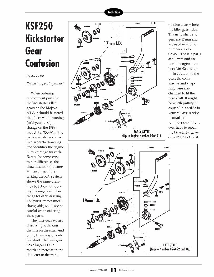
by Alex Dell
Product Support Specialist
When orderingreplacement parts for thekickstarter idler gears onthe Mojave ATV, it shouldbe noted that there was arunning (mid-year)design change on the1998 model KSF250-A12.The parts microficheshows two separatedrawings and identifiesthe engine number rangefor each. Except for somevery minor differencesthe drawings look thesame. However, as of thiswriting the KIC systemshows the same drawingsbut does not identify theengine number range foreach drawing. The partsare not interchangeable,so please be careful whenordering these parts.
The idler gear we arediscussing is the one thatfits on the small end ofthe transmission outputshaft.The new gear has alarger I.D. to match anincrease in the diameterof the transmission shaftwhere the idler gearrides. The early shaft and
gear are 17mm andare used in enginenumbers up to026492. The lateparts are 19mm andare used in enginenumbers 026493 andup.
In addition to thegear, the collar,washer and snap-ring were alsochanged to fit thenew shaft. It mightbe worth putting acopy of this article inyour Mojave servicemanual to remindyou should you everhave to repair thekickstarter gears on aKSF250-A12. �
KSF250KickstarterGear Confusion
19mm I.D.
LATE STYLE(Engine Number 026493 and Up)
EARLY STYLE(Up to Engine Number 026492)
17mm I.D.
build up. It also has aninternal temperature sen-sor, which activates theSpeed Limiting Opera-tional Warning (S.L.O.W.)system to reduce engineRPM if the EMM beginsto overheat. Excessivevoltage (over 45V) andhigh engine temperaturealso activate S.L.O.W.
A barometric pressuresensor housed inside theEMM senses altitudechanges for consistentrunning even as high as14,000 feet. This sensoruses a delicate diaphragmthat connects to a smallhole on the outside of theEMM. Do not use high airpressure to clean this cav-ity or you will rupture the
diaphragm.
Stratified and Homoge-nous Combustion
The engine uses a strat-ified combustion modefrom idle up to approxi-mately 5500 RPM. In thismode, the injector waitsuntil the piston closes theexhaust port then fires adense plume of fuel at thespark plug. Elsewhere inthe combustion chamberthe air / fuel mixture isextremely lean. The sparkplug fires up to 15 timesas the fuel passes by theelectrode. This uniquemulti-strike ignition burnsfuel thoroughly and keepsthe spark plug insulatorclean.
The homogenous com-
bustion mode starts above5500 RPM. In this mode,injector timing advancesand fuel is sprayed fur-ther into the cylinderwhere it bounces off thetop of the piston and dis-perses throughout thecombustion chamber in auniform air/fuel mixture.The ignition timing alsoadvances and the sparkplug fires only once percycle. Engineers were ableto bump the compressionratio from 5.8:1 to 6.6:1without detonation.
Diagnostic SoftwareTechnicians are thrilled
with the diagnostic capa-bilities of Kawasaki’sFICHT® system. Dealerscan now use a computerprogram to inspect andtest nearly all facets of theinjection and electrical
system. Your computermonitor will display errorcodes for any problemsrecognized by the EMMduring operation. You cancheck voltages and thecondition of all onboardsensors, some of themwithout even running theJet Ski. You can even viewthe percentage of time therider has run the engine ineach RPM range.
TrainingDirect Injection brings
too many changes to dis-cuss in this article. Pleaseattend the "hands on" 1100STX DI training classesoffered at each of ourTraining Centers. Manyclasses have been resched-uled so contact yourTraining Center for thelatest schedule and signup now!�
Cover
12WINTER 1999-’00 K-TECH NEWS
1100 STX D.I. -Cont’d
The diagnostic capabilities of the 1100 STX D.I. havebrought cheers from technicians
Diagnostic main menu(mainmenu.doc)
This R&D test boat knows only two throttle posi-tions: closed for no wake zones, and wide open!
RPM profile (rpmprofi.doc)