winner-take-all networks of o(n) complexitypapers.nips.cc/paper/151-winner-take-all-networks... ·...
TRANSCRIPT

WINNER-TAKE-ALL
NETWORKS OF O(N) COMPLEXITY
J. Lazzaro, S. Ryckebusch, M.A. Mahowald, and C. A. Mead California Institute of Technology
Pasadena, CA 91125
ABSTRACT
We have designed, fabricated, and tested a series of compact CMOS integrated circuits that realize the winner-take-all function. These analog, continuous-time circuits use only O(n) of interconnect to perform this function. We have also modified the winner-take-all circuit, realizing a circuit that computes local nonlinear inhibition.
Two general types of inhibition mediate activity in neural systems: subtractive inhibition, which sets a zero level for the computation, and multiplicative (nonlinear) inhibition, which regulates the gain of the computation. We report a physical realization of general nonlinear inhibition in its extreme form, known as winner-take-all.
We have designed and fabricated a series of compact, completely functional CMOS integrated circuits that realize the winner-take-all function, using the full analog nature of the medium. This circuit has been used successfully as a component in several VLSI sensory systems that perform auditory localization (Lazzaro and Mead, in press) and visual stereopsis (Mahowald and Delbruck, 1988). Winnertake-all circuits with over 170 inputs function correctly in these sensory systems.
We have also modified this global winner-take-all circuit, realizing a circuit that computes local nonlinear inhibition. The circuit allows multiple winners in the network, and is well suited for use in systems that represent a feature space topographically and that process several features in parallel. We have designed, fabricated, and tested a CMOS integrated circuit that computes locally the winner-take-all function of spatially ordered input.
703

704 Lazzaro, Ryckebusch, Mahowald and Mead
THE WINNER-TAKE-ALL CmCUIT
Figure 1 is a schematic diagram of the winner-take-all circuit. A single wire, associated with the potential Vc, computes the inhibition for the entire circuit; for an n neuron circuit, this wire is O(n) long. To compute the global inhibition, each neuron k contributes a current onto this common wire, using transistor T2 a.' To apply this global inhibition locally, each neuron responds to the common wire voltage Vc, using transistor Tla.' This computation is continuous in time; no clocks are used. The circuit exhibits no hysteresis, and operates with a time constant related to the size of the largest input. The output representation of the circuit is not binary; the winning output encodes the logarithm of its associated input.
Figure 1. Schematic diagram of the winner-take-all circuit. Each neuron receives a unidirectional current input 11;; the output voltages VI •.. VB represent the result of the winner-take-all computation. If II; = max(II ••• IB ), then VI; is a logarithmic function of 11;; if Ii <: 11;, then Vi ~ O.
A static and dynamic ana.lysis of the two-neuron circuit illustrates these system properties. Figure 2 shows a schematic diagram of a two-neuron winner-take-all circuit. To understand the beha.vior of the circuit, we first consider the input condition II = 12 = 1m. Transistors TIl ~d T12 have identical potentials at gate and source, and are both sinking 1m; thus, the drain potentials VI and V2 must be equal. Transistors T21 and T22 have identical source, drain, and gate potentials, and therefore must sink the identical current ICI = IC2 = Ic/2. In the subthreshold region of operation, the equation 1m = 10 exp(Vc/Vo) describes transistors Til and T12 , where 10 is a fabrication parameter, and Vo = kT/qlt. Likewise, the equation Ic/2 = 10 exp((Vm - Vel/Volt where Vm = VI = V2, describes transistors T21 and T22 . Solving for Vm(Im, Ie) yields
Vm = Voln(~:) + Voln(:;). (1)

Winner-Take-All Networks ofO(N) Complexity 705
Thus, for equal input currents, the circuit produces equal output voltages; this behavior is desirable for a winner-take-all circuit. In addition, the output voltage V m logarithmically encodes the magnitude of the input current 1m.
Figure 2. Schematic diagram of a two-neuron winner-take-all circuit.
The input condition II = 1m + Oi, 12 = 1m illustrates the inhibitory action of the circuit. Transistor Til must sink 0, more current than in the previous example; as a result, the gate voltage of Til rises. Transistors Tit and TI2 share a common gate, howeverj thus, TI2 must also sink 1m + 0,. But only 1m is present at the drain of T12 • To compensate, the drain voltage of T12 , V2, must decrease. For small OiS, the Early effect serves to decrease the current through Th , decreasing V2 linearly with 0,. For large o's, TI2 must leave saturation, driving V2 to approximately 0 volts. As desired, the output associated with the smaller input diminishes. For large OiS, Ie2 $!:::f 0, and Iel $!:::f Ie. The equation 1m + 0, = 10 exp(Ve/Vo) describes transistor Til' and the equation Ie = 10 exp((VI - Vel/Yo) describes transistor T21 • Solving for VI yields
(2)
The winning output encodes the logarithm of the associated input. The symmetrical circuit topology ensures similar behavior for increases in 12 relative to II.
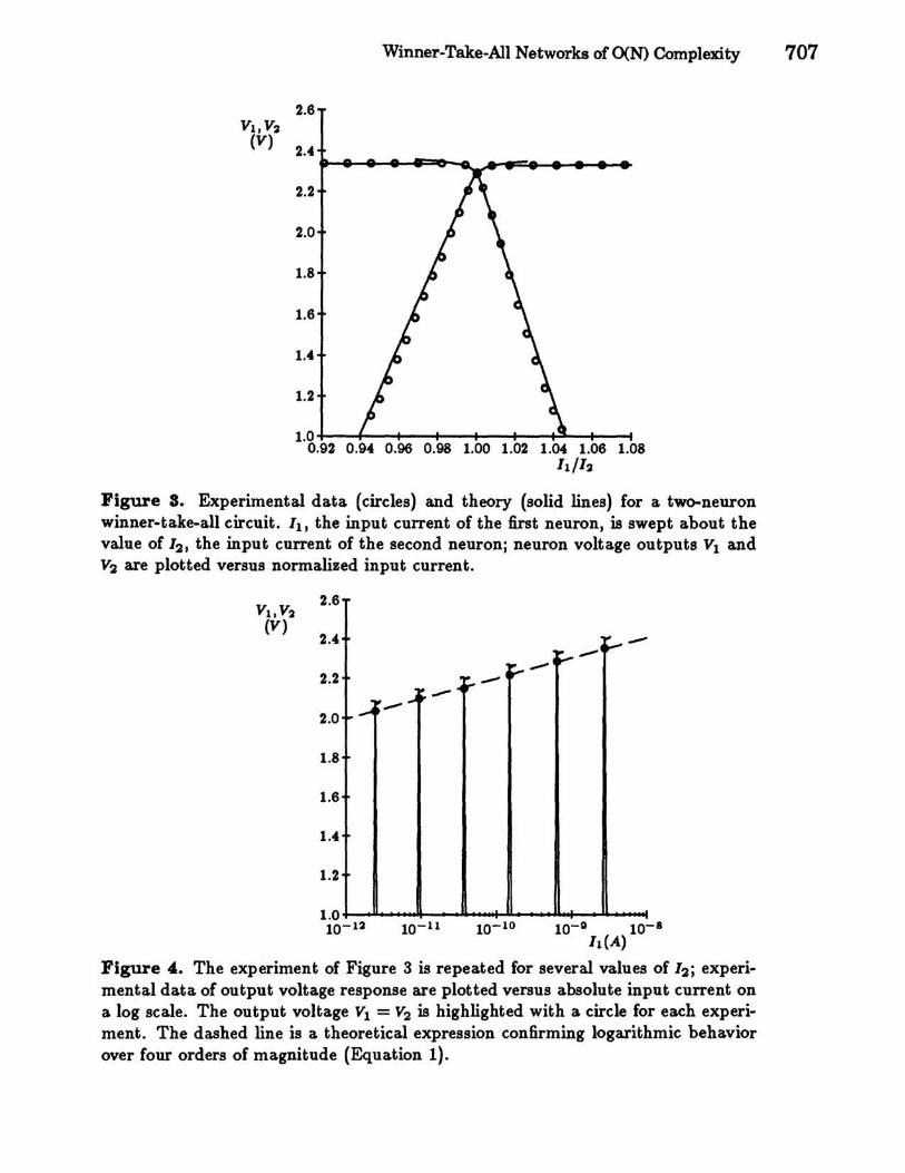
Equation 2 predicts the winning response of the circuit; a more complex expression, derived in (Lazzaro et.al., 1989), predicts the losing and crossover response of the circuit. Figure 3 is a plot of this analysis, fit to experimental data. Figure 4 shows the wide dynamic range and logarithmic properties of the circuitj the experiment in Figure 3 is repeated for several values of 12 , ranging over four orders of magnitude. The conductance of transistors Til and T1:a determines the losing response of the circuit. Variants of the winner-take-all circuit shown in (Lazzaro et. aI., 1988) achieve losing responses wider and narrower than Figure 3, using circuit and mask layout techniques.

706 Lazzaro, Ryckebusch, Mahowald and Mead
WINNER-TAKE-ALL TIME RESPONSE
A good winner-take-all circuit should be stable, and should not exhibit damped oscillations ("ringing") in response to input changes. This section explores these dynamic properties of our winner-take-all circuit, and predicts the temporal response of the circuit. Figure 8 shows the two-neuron winner-take-all circuit, with capacitances added to model dynamic behavior.
o
T 102 Vo
Ie
Figure 8. Schematic diagram of a two-neuron winner-take-all circuit, with capacitances added for dynamic analysis. 0 is a large MOS capacitor added to each neuron for smoothingj 0., models the parasitic capacitance contributed by the gates of Tu and T12 , the drains of T21 and T22, and the interconnect.
(Lazzaro et. al., 1988) shows a small-signal analysis of this circuit. The transfer function for the circuit has real poles, and thus the circuit is stable and does not ring, if 10 > 41(Oe/O), where 11 RlI2 Rl 1. Figure 9 compares this bound with experimental data.
H Ie > 41(00 /0), the circuit exhibits first-order behavior. The time constant OVo/I sets the dynamics of the winning neuron, where Vo = A:T /qK. Rl 40 mV. The time constant OVE/I sets the dynamics of the losing neuron, where VE Rl 50 v. Figure 10 compares these predictions with experimental data.
Vl,V, (V)
Winner-Take-All Networks ofO(N) Complexity 707
2.6
2.4
2.2
2.0
I.S
1.6
1.4
1.2
1.0+--+--+--+--..... ~I----t~--t---f 0.92 0.94 0.96 0.98 1.00 1.02 1.04 1.06 1.0S
II/I,
Figure 8. Experimental data (circles) and theory (solid lines) for a two-neuron winner-take-all circuit. II, the input current of the first neuron, is swept about the value of 12, the input current of the second neuron; neuron voltage outputs VI and V2 are plotted versus normalized input current.
2.6
I.S
1.6
1.4
1.2
10-11 10-10 10-0 10-8
IdA)
Figure 4. The experiment of Figure 3 is repeated for several values of 12; experimental data of output voltage response are plotted versus absolute input current on a log scale. The output voltage VI = V2 is highlighted with a circle for each experiment. The dashed line is a theoretical expression confirming logarithmic behavior over four orders of magnitude (Equation 1).

708 Lazzaro, Ryckebusch, Mahowald and Mead
1
Figure 9. Experimental data (circles) and theoretical statements (solid line) for a two-neuron winner-take-all circuit, showing the smallest 10 , for a given I, necessary for a first-order response to a small-signal step input.
Figure 10. Experimental data (symbols) and theoretical statements (solid line) for a two-neuron winner-take-all circuit, showing the time constant of the first-order response to a small-signal step input. The winning response (filled circles) and losing response (triangles) of a winner-take-a.ll circuit are shownj the time constants differ by several orders of magnit ude.

Winner~Take~AlI Networks ofO(N) Complexity 709
THE LOCAL NONLINEAR INHIBITION CIRCUIT
The winner-take-all circuit in Figure 1, as previously explained, locates the largest input to the circuit. Certain applications require a gentler form of nonlinear inhibition. Sometimes, a circuit that can represent multiple intensity scales is necessary. Without circuit modification, the winner-take-all circuit in Figure 1 can perform this task. (Lazzaro et. al., 1988) explains this mode of operation.
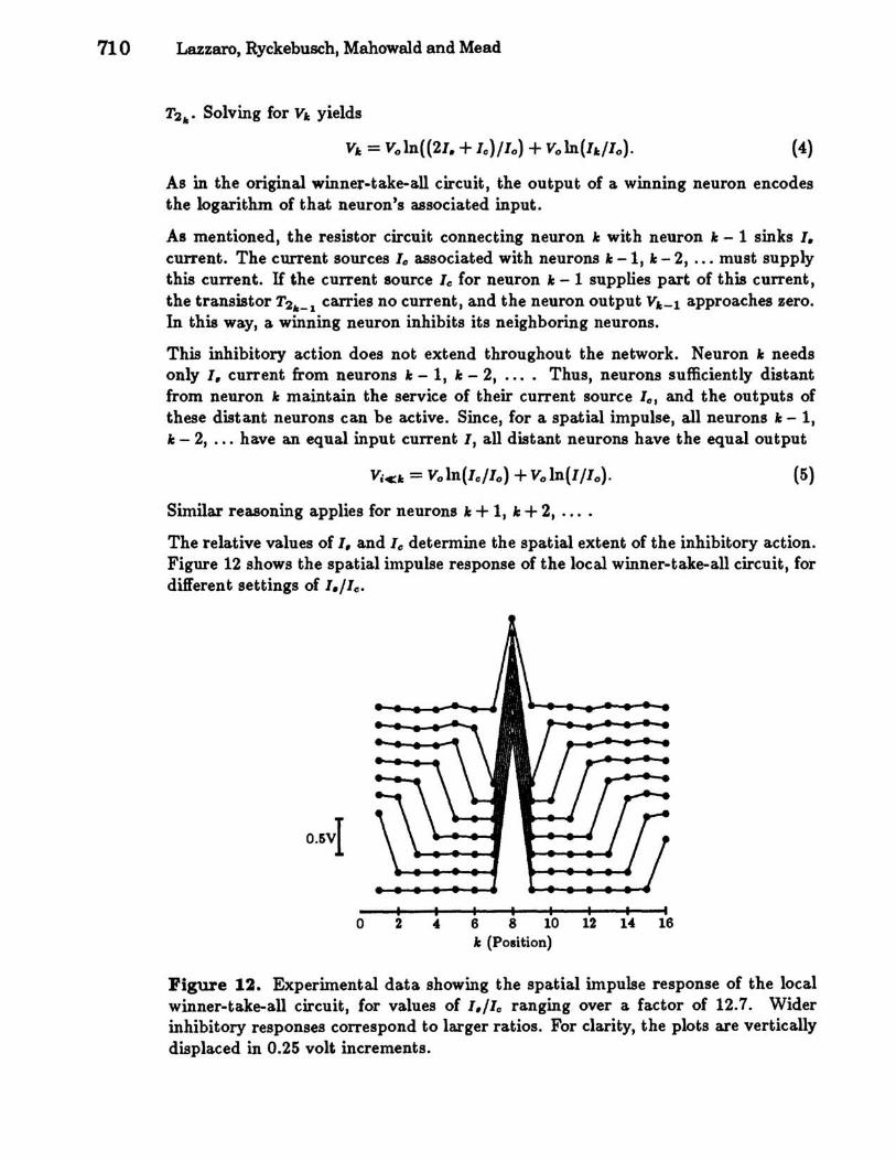
Other applications require a local winner-take-all computation, with each winner having inHuence over only a limited spatial area. Figure 12 shows a circuit that computes the local winner-taite-all function. The circuit is identical to the original winner-take-all circuit, except that each neuron connects to its nearest neighbors with a nonlinear resistor circuit (Mead, in press). Each resistor conducts a current Ir in response to a voltage ~V across it, where Ir = I.tanh(~V/(2Vo)). 1., the saturating current of the resistor, is a controllable parameter. The current source, 10, present in the original winner-take-all circuit, is distributed between the resistors in the local winner-take-all circuit.
Figure 11. Schematic diagram of a section of the local winner-take-all circuit. Each neuron i receives a unidirectional current input Iii the output voltages Vi
represent the result of the local winner-take-all computation.
To understand the operation of the local winner-take-all circuit, we consider the circuit response to a spatial impulse, defined as 1" :> 1, where 1 == h~". 1,,:> 1"-1 and 1,,:> 1"+1, so Ve:,. is much larger than Ve:,._l and Ve:lI+l' and the resistor circuits connecting neuron 1: with neuron 1: - 1 and neuron 1: + 1 saturate. Each resistor sinks 1. current when saturatedj transistor T2,. thus conducts 21. + Ie: current. In the subthreshold region of operation, the equation 1" = 10 exp(Ve:,. /Vo) describes transistor TI ,., and the equation 21. + Ie = Ioexp((V" - Ve:,.)/Vo) describes transistor
710 Lazzaro, Ryckebusch, Mahowald and Mead
T2,.. Solving for VA: yields
VA: = voln((2I. + 10 )/10 ) + voln(IA:/lo). (4)
As in the original winner-take-all circuit, the output of a winning neuron encodes the logarithm of that neuron's associated input.
As mentioned, the resistor circuit connecting neuron Ie with neuron Ie - 1 sinks 1. CUlTent. The current sources 10 associated with neurons Ie -1, Ie - 2, ... must supply this current. If the current source 10 for neuron Ie - 1 supplies part of this current, the transistor T2,._1 carries no current, and the neuron output VA:-l approaches zero. In this way, a winning neuron inhibits its neighboring neurons.
This inhibitory action does not extend throughout the network. Neuron Ie needs only 1. current from neurons Ie - 1, Ie - 2, .... Thus, neurons sufficiently distant from neuron Ie maintain the service of their current source 10, and the outputs of these distant neurons can be active. Since, for a spatial impulse, all neurons Ie - 1, Ie - 2, ... have an equal input current I, all distant neurons have the equal output
(5)
Similar reasoning applies for neurons Ie + 1, Ie + 2, ....
The relative values of 1. and 10 determine the spatial extent of the inhibitory action. Figure 12 shows the spatial impulse response of the local winner-take-all circuit, for different settings of 1./10 ,
I I I I I o 2 4 6 8 10 12 14 16
Ie (Pollition)
Figure 12. Experimental data showing the spatial impulse response of the local winner-take-all circuit, for values of 1./10 ranging over a factor of 12.7. Wider inhibitory responses correspond to larger ratios. For clarity, the plots are vertically displaced in 0.25 volt increments.
Winner-Take-All Networks ofO(N) Complexity 711
CONCLUSIONS
The circuits described in this paper use the full analog nature of MOS devices to realize an interesting class of neural computations efficiently. The circuits exploit the physics of the medium in many ways. The winner-take-all circuit uses a single wire to compute and communicate inhibition for the entire circuit. Transistor TI,. in the winner-take-all circuit uses two physical phenomena in its computation: its exponential current function encodes the logarithm of the input, and the finite conductance of the transistor defines the losing output response. As evolution exploits all the physical properties of neural devices to optimize system performance, designers of synthetic neural systems should strive to harness the full potential of the physics of their media.
Acknow ledgments
John Platt, John Wyatt, David Feinstein, Mark Bell, and Dave Gillespie provided mathematical insights in the analysis of the circuit. Lyn Dupre proofread the document. We thank Hewlett-Packard for computing support, and DARPA and MOSIS for chip fabrication. This work was sponsored by the Office of Naval Research and the System Development Foundation.
References
Lazzaro, J. P., Ryckebusch, S., Mahowald, M.A., and Mead, C.A. (1989). WinnerTake-All Networks of O(N) Oomplexity, Caltech Computer Science Department Technical Report Caltech-CS-TR-21-88.
Lazzaro, J. P., and Mead, C.A. {in press}. Silicon Models of Auditory Localization, Neural Oomputation.
Mahowald, M.A., and Delbruck, T.I. (1988). An Analog VLSI Implementation of the Marr-Poggio Stereo Correspondence Algorithm, Abstracts of the First Annual INNS Meeting, Boston, 1988, Vol. I, Supplement I, p. 392.
Mead, C. A. (in press). Analog VLSI and Neural Systems. Reading, MA: AddisonWesley.