wings harness / container...
TRANSCRIPT

Sunrise Manufacturing International, Inc.
6520 Fort King Rd.
Zephyrhills, FL 33542
Ph: 813.788.1910
Fax: 813.788.2799
E-mail: [email protected]
Website: www.skydivewings.com
Owner’s Manual for Packing, Donning, and Maintenance of the
Wings Harness / Container System
Manual P/N: SRI-700 JUNE 2015 Serial Number: ___________________


Page 2
This authorization is not transferable to another person or location and is effective until surrendered, withdrawn, or otherwise terminated by the Administrator.
Your responsibilities as a holder of a TSO authorization are outlined in 14 CFR part 21, subpart 0, and 14 CFR part 21.3.
The Airframe engineer for your program is Cindy Lorenzen, telephone number (770) 703-6078. The Technical Information Specialist is Lorraine Bush, telephone number (770) 703~6044.
Sincerely,
~'.""..,,'.<~,-",-

WARNING!
SKYDIVING / PARACHUTING IS A HIGH RISK ACTIVITY WHICH CAN CAUSE OR RESULT IN SERIOUS INJURY
OR DEATH.
The following information must be read and understood before any use of this equipment: USER KNOWS THE RISKS OF SKYDIVING AND ACCEPTS THAT: Skydiving can cause death and/or serious injuries. Many of these deaths and injuries can be attributed to equipment problems or malfunctions. Skydiving equipment can fail, even if all possible precautions are taken by the user, the equipment manufacturers and everyone else involved with the jump. Failure to activate the main or reserve parachute (or follow emergency procedures) at a safe altitude, and/or equipment failure can result in severe injury or death. IT IS THE USER’S RESPONSIBILITY TO: Receive proper training before any use of all skydiving equipment. Be extremely careful and cautious. Read and Understand all owner’s and operating manuals for all skydiving equipment. Thoroughly check all skydiving equipment and replace any defective or worn component prior to use. Review emergency procedures before each use of this and all skydiving equipment. Check equipment warnings –
DO NOT EXCEED EQUIPMENT LIMITATIONS!

WARNING!
Never violate the training and experience requirements for the specific equipment use. DISCLAIMER – STATEMENT OF WARRANTY
Because of the unavoidable dangers involved in the use of this and all parachute equipment – Sunrise Manufacturing International, Inc., (including but not limited to all owners, officers, staff, and employees), hereafter referred to as (SMI) makes no warranties of any kind, expressed or implied. The liability of the seller is limited to replacing defective parts found upon examination by the manufacturer to be defective in material or workmanship within 7 days after purchase and found not to have been caused by an accident, improper use, alteration, tampering, abuse or lack of care on the part of the purchaser. By using this equipment or allowing it to be used by others, owner/buyer waives any liability of SMI for personal injuries or any other damages arising from such use. Any promise or representations inconsistent with or in addition to the Statement of Warranty are not authorized by SMI and shall not be binding.
!WARNING! Parachuting is a hazardous activity that can result in serious injury or death. Failure to follow all warnings, instructions, and required procedures may result in serious injury or DEATH! Parachutes sometimes malfunction even when they are properly designed, built, assembled, packed, maintained and used. All rights reserved. No part of this publication may be reproduced, stored in a retrieval system, or transmitted, in any form, or by any means, electronic, mechanical, photocopying, recording, or otherwise, without written permission of SMI, Inc. Text and Copyright 2015 by Sunrise Manufacturing International, Inc. / SMI, Inc.

1
Table of Contents
Chapter 1 Product Information
1.1 Sunrise Manufacturing International, Inc.
1.2 Harness / Container Information
Chapter 2 Technical Information
Chapter 3 Tools
Chapter 4 Reserve Parachute
2.1 Main Container Harness Specs.
2.2 Main Container Assembly Specs.
4.1 Inspections
4.1.1 Harness /Container
4.1.2 Reserve Parachute
4.2 Assembly
4.2.1 Assembly of the Reserve Parachute
Assembly of the Reserve Parachute using Rapide Links
Installing the Slider Bumpers
Assembly of the Reserve Parachute using Soft Links
4.2.2 Installing Toggles to Control Lines
4.2.3 Assembly of the Reserve Static Line
4.2.4 Installing the Reserve Closing Loop
4.2.5 Installing the Automatic Activation Device (AAD)
4.3 Packing the Reserve Parachute
4.3.1 Setting the Reserve Parachute Brakes
4.3.2 Flat Packing the Reserve Parachute
4.3.3 PRO-Packing the Reserve Parachute
4.3.4 Closing with the “Reserve Boost”
3.1 Packing Tools Checklist
3.2 Recommended Packing Tools
pg. 1
pg. 1
pg. 1
pg. 1
pg. 1
pg. 2
pg. 1
pg. 1
pg. 3
pg. 4
pg. 4
pg. 4
pg. 5
pg. 6
pg. 8
pg. 9
pg. 10
pg. 11
pg. 12
pg. 12
pg. 13
pg. 23
pg. 34
Sunrise Manufacturing International, Inc. WINGS MANUAL

2
Chapter 6 Donning the Wings Harness /Container
Chapter 7 Operations of the WINGS Harness / Container
6.1 Proper Fit of the Wings Harness / Container
6.2 Equipment Check of the Wings Harness / Container
6.3 Donning the Wings Harness / Container
7.1 Deploying the Main Pilot Chute 7.2 Releasing the Main Parachute 7.3 Pulling the Reserve Handle
pg. 1
pg. 1
pg. 2
pg. 1 pg. 1 pg. 1
Chapter 5 Main Parachute
5.1 Main Parachute Inspection
5.2 Assembly Instructions
5.2.1 Assembly of Main Canopy
Assembly of Main Canopy using Rapide Links
Installation of Slider Bumpers
Assembly of Main Canopy using Soft Links
5.3 Installing the Steering Toggles to the Main Risers
5.4 Attaching the Deployment Bag to the Canopy
5.5 Installation of the Main Canopy Release Handle
5.6 Attaching the 3-Ring Risers
5.7 Stowing the Main Steering Toggles
5.8 Flat Packing the Main Canopy
5.9 PRO-Packing the Main Canopy
5.10 Closing the Main Container for Pull-out Pilot-chute
pg. 1
pg. 2
pg. 2
pg. 2
pg. 3
pg. 4
pg. 6
pg. 7
pg. 8
pg. 9
pg. 10
pg. 11
pg. 19
pg. 28
Sunrise Manufacturing International, Inc. WINGS MANUAL
pg. 1
pg. 1
pg. 1
pg. 2
Chapter 8 Care and Maintenance
8.1 General Storage Requirements
8.2 Storage Specifics to Parachutes
8.3 In-Storage Inspections
8.4 Water Contamination Guidelines
3
pg. 1
pg. 2
pg. 4
pg. 5
pg. 7
pg. 8
pg 9
pg. 13
pg. 17
pg. 20
pg. 22
pg. 24
9.1 Installing the Optional “Reserve Boost” RSL Extension Lanyard
9.2 Assembly of the AFF Left Side JM Handle for T/O Pilot-chute
9.3 Closing the Main Container for the AFF Left Side JM Handle- T/O
9.4 Assembly of the AFF Left Side JM Handle for Ripcord
9.5 Closing the Main Container for AFF Left Side JM Handle- Ripcord
9.6 Closing the Main Container for Ripcord
9.7 Closing the Main Container for Spring-loaded P/C Assist Static-Line
9.8 Closing the Main Container for T/O Pilot-chute Assist Static-Line
9.9 Closing the Main Container for Direct Bag Static-Line
9.10 Using the Optional Semi-Stowless Deployment Bag
9.11 Stowing the Optional Swoop Toggles & Risers
9.12 Replacing the Magnets in the Riser Covers
Sunrise Manufacturing International, Inc. WINGS MANUAL
Notes
Chapter 9 Special Instructions
pg. 1

4
Sunrise Manufacturing International, Inc. WINGS MANUAL

Chapter 1
Product Information
Sunrise Manufacturing International, Inc. WINGS MANUAL
1.1 Sunrise Manufacturing
International, Inc. Information
1
During the early 1990’s, with increasing freefall speeds, smaller parachute options and a changing skydiving market, there was an obvious need for a fresh approach to skydiving container systems. The Wings harness/ container system was designed with those needs in mind. After many design and engineering trials, testing began for the FAA TSO C23d approval designation. The Wings Single Harness Reserve Parachute is approved for use by a person up to 254 lbs /115 kg fully equipped up to 150 knots. Located in Zephyrhills, Florida USA, Sunrise Manufacturing International, Inc. has since gone on to produce more than 10000 of these containers for sport, student and military applications. SMI, Inc. is dedicated to address your needs with several harness/ container options.
While each system is available in a combination of sizes and options, several Standard Features are included on the WINGS Harness/Container system: Main Pin Cover – Having an upward facing
pin cover creates the ultimate in pin protection from unintended knocks or bumps causing premature pin extraction.
Bridle and Riser Cover Protection – Zero
exposed riser or main bridle ensures proper function in any manner of orientation or use.
Main Risers with Front Dive Loops and
Velcro-less Toggles. Foam Padded Yoke, Back Pad, and Leg
Straps for added comfort. Automatic Activation Device (AAD) Set-up -
ready for installation of many of the AAD’s in use today.
Reserve Static Line (RSL) Set-up - ready for
installation. Single Pin Reserve Closing.
Type VII Mil-SPEC Harness and Reserve Risers.
1000 Denier Cordura for durable long lasting
use.
1.2 WINGS Harness / Container
Information

Sunrise Manufacturing International, Inc. WINGS MANUAL
OPTIONS for the Wings Harness/ Container include:
2
Reserve Static Line (RSL) Lanyard connecting the Left Main Riser and the Reserve Ripcord Cable which allows minimum altitude loss during the reserve opening in the event of a cutaway.
“Reserve Boost” - Main Assisted
Reserve Deployment (MARD) System. Reserve Pin Inspection Window. Articulated Harness. Spacer Foam Back Pad and Leg Pads. Quilted Back Pad. Cut-in Laterals. Stainless Steel Hardware. Personalized Monograms. Mid-flap Stripes Pinstripes. Custom Colored Hacky. Custom Colored Free-fly Handle. BOC, Ripcord or Static-line Main
Deployment. Custom Colored Pillow Reserve Handle. Custom Colored Cut-away Handle. Hard Inserts in Pillow Handles. Collapsible Main Pilot-chute - Zero-P or F-111. Throw-out or Pull-out Main Pilot-chute. Type 17 or Type VIII Main Risers.
STUDENT OPTIONS for the Wings Harness/ Container include:
Spring-loaded Pilot Chute with Chest or Hip Mounted Ripcord.
AFF Left Side Jumpmaster Handle for
Throw-out Pilot Chute. AFF Left Side Jumpmaster Handle for
Spring-loaded Pilot Chute. Static-line for Direct Bag, T/O Pilot-
Chute Assist or Spring-loaded Pilot-Chute Assist.
AAD Inspection Window on Reserve
Cover Flap. B-12 or Quick Ejector Hardware.
Swoop Risers. CReW Risers and Toggles. Semi-Stowless D-Bag. Tie Dye Fabric. Magnetic Riser Covers. Hook-knife on Mud-flap.

Chapter 2
Technical Information
Sunrise Manufacturing International, Inc. WINGS MANUAL
2.1 Container Harness Specs:
1
2.2 Container Assembly Specs:
Harness is Tested and Approved under FAA TSO C23D.
Main Lift Webbing, Type 7 Mil-W-4088
Tensile Strength, 6000 lbs. Leg Straps and Laterals, Type 7 Mil-W-4088
Tensile Strength, 6000 lbs. Chest Strap, Doubled Type 8 Mil-W-4088
Tensile Strength, 4000 lbs. or Chest Strap, Doubled Type 17 Mil-W-4088
Tensile Strength, 2500 lbs. Reserve Risers, Type 7 Mil-W-4088
Tensile Strength, 6000 lbs. Main Harness Riser Ring, No.1 or No.8
Proof Load, 2500 lbs. Optional Adjustable Hip Ring, 555-2 Ring. Leg Strap Hardware, PS 22040-1 or Flip-Flop
Stainless Steel Adjuster Tensile Strength, 2500 lbs. Chest Strap Hardware, PS 70101-1 or 1”
Quick Fit Adapter Type 17 Mini Risers, Mil-W-4088, Tensile
Strength, 2500 lbs. Large Ring Main Risers, Type 8 Mil-W-4088,
Tensile Strength, 4000 lbs.
Reserve Container and all pertaining parts are Tested and Approved under FAA TSO C23d.
Automatic Activation Device (AAD) set-up
with the Control Unit in the Reserve Top Cover Flap or Back Pad.
1000 Denier Cordura lined w/ 1/4”
Para-pack nylon backed black foam. Inboard Reserve and Cutaway Handles. 0# Stainless Steel Grommets. All Stainless Steel Housings .040 Nylon Stiffeners .062 Aluminum Reserve Floor Plate 500 Denier Cordura Main Deployment
Bag. Velcro-less Main Toggles. Stainless Steel Reserve Ripcord Handle. Left Riser Reserve Static Line (RSL).

Sunrise Manufacturing International, Inc. WINGS MANUAL
2

Chapter 3
Tools
1
3.1 Packing Tool Check-List
Use this page to record which tools are used during the packing of your SMI, Inc. WINGS Harness/Container System. Mark which tools, and how many were used for packing and document all tools after work is complete.
Tool used: Pre-packing Post-packing
Packing paddle ____ used ____ used
Shot bag ____ used ____ used
.22 Gun cleaning rod ____ used ____ used
Pull up cord ____ used ____ used
Leverage device ____ used ____ used
Temporary pin ____ used ____ used
Mechanical Tension Device ____ used ____ used
Closing plate ____ used ____ used
Additional tools:
________________ ____ used ____ used
________________ ____ used ____ used
________________ ____ used ____ used
________________ ____ used ____ used
________________ ____ used ____ used
________________ ____ used ____ used
________________ ____ used ____ used
________________ ____ used ____ used
Sunrise Manufacturing International, Inc. WINGS MANUAL
2
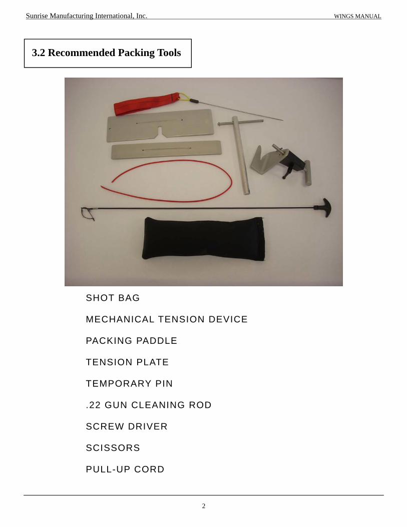
SHOT BAG MECHANICAL TENSION DEVICE PACKING PADDLE TENSION PLATE TEMPORARY PIN .22 GUN CLEANING ROD SCREW DRIVER SCISSORS PULL-UP CORD
Sunrise Manufacturing International, Inc. WINGS MANUAL
3.2 Recommended Packing Tools

Chapter 4
Reserve Parachute
1
Main Lift Web Optional Adjustable Main Lift Webbing -
Sizing identification symmetrical (same color). Fold-over is present and sewn. Harness stitching 3 and 4 point stitching is intact, no broken stitches. Selvage edge is intact. Webbing is free of wear and abrasions. Velcro for Main Release Handle and Reserve Ripcord is correct and in place. Main Release and Ripcord Housings are in place and secured. Chest Strap fold-over is present and sewn.
4.1.1 Harness / Container
Laterals Symmetrical (if adjustable) Harness stitching present and correct.
Leg Straps/ Leg Pads
Fold-over is present and sewn. Leg pads have reinforcing bar tacks. Harness stitching is present and correct.
Reserve Container Grommets secure without burrs or sharp edges. Binding tape is secure and sewn correctly. AAD pocket and window sewn in place for AAD set-up. Floor Plate sewn in place. RSL Ring in place.
Reserve Risers Symmetrical Harness stitching present and correct. Toggles and Velcro in place. Guide rings present, free of wear, no abrasions
Sunrise Manufacturing International, Inc. WINGS MANUAL
4.1 Inspections

2
Reserve Free-Bag and Pilot-Chute
Grommets secure without burrs or sharp edges. Bridle bar-tacked. Spring crimped, TSO Label present. Cap and snaps present and secure. Free bag size matches container. Velcro and pocket secure, TSO Label present.
Reserve Ripcord
Handle is correct shape and smooth. No broken strands of cable. Straight pin. Ball & Shank in place.
Reserve Static-Line (RSL) Bartacks are present. No Corrosion or wear. Velcro secure and in good shape. Release clasp is in working order. Mini Ring present and round in shape.
Main Container
Binding Tape, present and no stitches missing. Closing Loop Retainer present. Grommets, free of burrs, sharp edges. Housings are secure and no sharp edges. Main Parachute Release Handle is clean, free-moving in housings.
Sunrise Manufacturing International, Inc. WINGS MANUAL

3
4.1.2 Reserve Parachute
Links should be: Clean of corrosion, debris and without cracks or visible damage. No sharp or raw edges. Free moving barrel, which should be able to tighten 2 ¾ turns from first
engagement of the barrel without resistance.
Rapide Link Covers Covers should be firmly seated on top of links. Covers tacked in place to prevent slippage.
Lines No excessive fraying or damage to lines. Continuity is correct. Bartacks sewn correctly on each line. Each line is without twists and correctly installed from link to parachute,
passing through the correct slider grommet.
Slider Slider is without holes, burns, or other damage. Reinforcement tape in place and secure. Grommets seated correctly without burrs or damage.
Bottom Skin
Inspect each cell for any tears, fraying or other damage. Seams and attachment points stitched correctly and evenly.
Ribs
Cross ports without damage. Stitching correct on seams. Reinforcing tape present on loaded ribs. No other damage on entire rib section.
Top Skin
Seams are sewn correctly. Leading edge bar tacks are in place. Control line attachment points are reinforced.
Stabilizers
Slider stops are present and secured. Lines bar tacked to lower edge of stabilizer. Slack is present in stabilizer when line is taut.
Sunrise Manufacturing International, Inc. WINGS MANUAL

4.2 Assembly Instructions
4
After inspecting the Parachute and the Wings
Harness/Container System, hang or lay the
parachute out on the ground with the nose
section on the ground and the Wings Harness/
Container System oriented face down.
When using Rapide Links, check to see that
bumpers have been installed. See pg.5 for
instructions on bumper installation.
4.2.1 Assembly of Reserve Canopy.
Fold the ends of the risers to narrow the top
section. Place the link of the Right Front line-set
onto the end of the Right Front Riser. Be
careful not to twist the line sets.
Tighten the barrel finger tight and then an
additional ¼ turn with a small wrench until the
link is tight. Pull the Bumper down and secure
as per the instructions on page 5 of this chapter.
Begin the assembly process by ensuring that all
lines are connected to the links correctly with
the Outboard “A”-lines on the outside of the link
and the Center “A”-line towards the inside of the
link, the longer side of the link towards the riser.
Once the continuity of the lines is set, ensure
the slider is correctly oriented; the slider should
be longer span-wise than chord-wise, with the
reinforcing tape of the slider on the side facing
the reserve parachute.
Inboard “A” line
Outboard “A” line
Sunrise Manufacturing International, Inc. WINGS MANUAL
Right Front Riser Left Front Riser Inboard “A” line
Outboard “A” line
Repeat these steps for the two Rear Risers,
ensuring that the Outboard “C” line is on the link
first.
Assembly of Reserve Canopy using Rapide Links.
5
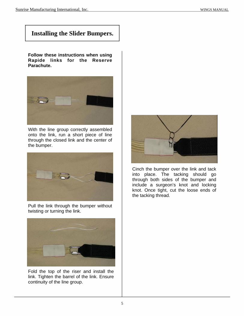
Installing the Slider Bumpers.
With the line group correctly assembled onto the link, run a short piece of line through the closed link and the center of the bumper.
Pull the link through the bumper without twisting or turning the link.
Fold the top of the riser and install the link. Tighten the barrel of the link. Ensure continuity of the line group.
Cinch the bumper over the link and tack into place. The tacking should go through both sides of the bumper and include a surgeon’s knot and locking knot. Once tight, cut the loose ends of the tacking thread.
Sunrise Manufacturing International, Inc. WINGS MANUAL
Follow these instructions when using Rapide links for the Reserve Parachute.

6
Always Read and Follow the Instructions
provided by the Soft Link manufacturer.
Assembly of Reserve Canopy using Soft Links.
Pass the Soft Link through the Reserve Riser.
Sunrise Manufacturing International, Inc. WINGS MANUAL
Pass the lead of the Soft Link through the
lines again.
Depending on the Soft Link Manufacturer you
may have to pass it through the Reserve
Riser and the lines once or twice again.
Follow the manufacturer’s instructions.
While keeping the continuity of the lines in
order pass the Soft Link through each line.
Fold the end of the Reserve Riser as shown.

7
Should look like this.
Sunrise Manufacturing International, Inc. WINGS MANUAL
Tuck the Loop and Lead ends under the
Reserve Riser.
A hand-tack may be used to secure it under
the Reserve Riser.
After passing the Soft Link through the lines
and the Reserve Riser the proper number of
times pass the Soft Link lead through the
loop of the other end of the Soft Link.
Pass the Loop end back through the Lead then
tighten the knot formed
LEAD
LOOP

8
4.2.2 Installing the Reserve Steering
Toggles onto the Control Lines.
Pass the loop of the Control Line over the bottom of the toggle.
Tighten the loop up to the grommet. Repeat for the other toggle. The parachute brakes are now ready to be stowed.
Feed the Control Line through the rear of the toggle.
Once the Reserve Parachute is assembled
onto the Reserve Risers, feed the Control
Line through the appropriate slider grommet
and guide ring on the reserve riser.
Sunrise Manufacturing International, Inc. WINGS MANUAL

4.2.3 Assemble the Reserve Static
Line. (RSL) Optional
Install the cable of the Reserve Ripcord Handle into the Reserve Ripcord Housing on the left side Main Lift Webbing. Install the Reserve Ripcord Handle into the Reserve Ripcord Pocket.
Mate the Pile Velcro of the RSL with the Hook Velcro under the RSL channel on the Left Side of the Yoke. Start at the lower end of the channel and proceed to the top. Close cover when Velcro has been mated and RSL has been installed.
Pass the Ripcord Cable through the guide ring on the Container. Installation is complete.
If using the “Reserve Boost” pass the Ripcord Cable through the guide ring in the middle of the RSL.
9
Sunrise Manufacturing International, Inc. WINGS MANUAL
Pass the Ripcord Cable through the guide ring of the RSL.

Sunrise Manufacturing International, Inc. WINGS MANUAL
Pictured above is the Reserve Container with the new dual grommet bottom plate. This configuration allows the closing loop to be inserted from the top of the first grommet then up from the bottom through the second grommet.
10
1
2
Begin by lifting the elastic covering of the top grommet. Feed the closing loop down through the top grommet.
Pass the closing loop up through the bottom grommet as shown.
4.2.4 Installing the Reserve Closing
Loop.
Tuck the excess closing loop under the elastic cover. Installation of the Reserve Container Closing Loop is complete.

11
Read the AAD Owner’s Manual and become familiar with the different components of the unit and details of its use. Insert the Processing Unit into the spandex pocket located on the bottom wall of the reserve container. (fig. 1) Route the Release Unit under the reserve floor plate and through the slot and elastic housing. Stow the excess cable in the spandex pouch. (fig.2) Route the Control Unit through the channel next to the floor plate. Once threaded through this channel, insert the Control Unit into the Back Pad pocket or the Reserve Cover Flap. (fig. 3) Once secured in the spandex pocket, the display should be clearly visible through the clear plastic window of the back pad. Stow the excess cable in the channel or spandex pocket. Close the Velcro pocket on the spandex pouch. Installation is complete.
Processing Unit
Control Unit
Release Unit
4.2.5 Installing the Automatic
Activation Device (AAD)
Sunrise Manufacturing International, Inc. WINGS MANUAL
Installation complete.
Fig. 1
Fig. 2
Fig. 3

12
4.3.1 Setting the Reserve Canopy
Brakes.
After assembling the toggles correctly, pull
the control line so that the “cat’s eye” of the
control line is just below the guide ring
located on the riser.
Insert the toggle into the “cat’s eye”.
Tuck the bottom of the toggle into the
keeper.
“S”-fold the excess control line next to the toggle tip.
Wrap and secure the Velcro around the toggle tip. Repeat steps for the other brake.
Sunrise Manufacturing International, Inc. WINGS MANUAL
4.3. Reserve Packing Instructions

13
4.3.2 Flat Pack Method of the Reserve
Parachute.
Place the slider at the connector links. (NOT SHOWN for clarity of line groups)
Grasp the Rear Line and Control Line groups in the LEFT Hand and the Front Line groups in the RIGHT Hand. Walk towards the parachute, leaving the slider at the risers and separating the line groups as you go. Once at the stabilizer edge, shake the parachute from side to side.
Walk to the top of the canopy and: Count and flake out the cells leading edges. Count and flake out the B-line seams. Count and flake out the C-line seams. Count and flake out the D-line seams. Count and flake out the control lines and the remainder of the trailing edge of the canopy.
Fold the leading edge under the A-line group.
While maintaining control of the line groups, lay out the parachute in front of you and away from the Harness/Container. Maintaining line tension will help in later steps.
BEFORE PROCEEDING: NOTE THE MAXIMUM OPERATING WEIGHT OF THE RESERVE CANOPY AND MARK ON THE DATA CARD!
Sunrise Manufacturing International, Inc. WINGS MANUAL

14
Grasp the B-line group under slight tension and fold over the A-line group.
Grasp the C-line group under slight tension and fold over the B-line group.
Grasp the D-line group under slight tension and fold over the C-line group.
Pull out the left three (3) cells of the nose towards the left. Pull out the right three (3) cells of the nose towards the right. Flake the control lines onto the center of the canopy, splitting the groups and corresponding trailing edge into half. The Reserve Brakes may be stowed at this time. See page 12.
Flake the tail of the parachute on top of itself. This step will involve folding half cells between the control lines and whole cells on the remainder of the trailing edge.
Bring the slider up from the connector links until it is touching the slider stops and quarter the slider between the slider stops.
Sunrise Manufacturing International, Inc. WINGS MANUAL

15
Pull tail down carefully to just above slider and cocoon the parachute by wrapping the tail around the flaked cells. DO NOT include the nose in this cocoon. The cocoon should roughly be the same width as the free bag.
“S”-fold the three (3) nose cells under the corresponding side of the parachute.
Carefully squeeze out any trapped air.
“S” -fold the canopy on top of itself.
“S”-fold lower portion of canopy up to the trailing edge of the parachute and place under the trailing edge.
Place the Free-bag under the canopy.
Sunrise Manufacturing International, Inc. WINGS MANUAL

Fold the canopy back over itself.
Tuck the canopy into the corners of the Free-bag.
Use the Free-bag bridle to hold the safety stow in place.
“S”-fold the canopy over onto itself once again.
Smooth out and make sure that the canopy is no wider than the Free-bag.
16
Sunrise Manufacturing International, Inc. WINGS MANUAL

17
Grasp “ear” and “S”-fold it on top of itself.
Roll the center material to the depth of the Free-bag. Place your knee on to hold in place.
Place into the Free-bag. Repeat the other side “ear”. Straighten and smooth out the “ear”
formed after following the center seam.
Follow the center seam to the end.
Sunrise Manufacturing International, Inc. WINGS MANUAL
18
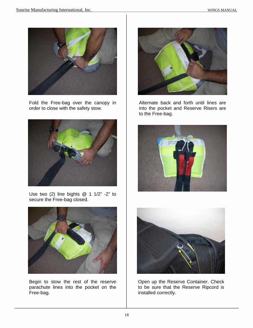
Fold the Free-bag over the canopy in order to close with the safety stow.
Use two (2) line bights @ 1 1/2” -2” to secure the Free-bag closed.
Begin to stow the rest of the reserve parachute lines into the pocket on the Free-bag.
Alternate back and forth until lines are into the pocket and Reserve Risers are to the Free-bag.
Sunrise Manufacturing International, Inc. WINGS MANUAL
Open up the Reserve Container. Check to be sure that the Reserve Ripcord is installed correctly.

19
Thread a pull-up cord through the closing loop and the center grommet of the Free-bag.
Carefully lift the Free-bag. Check to be sure that the AAD cutter is installed correctly and that the closing loop goes through the cutter.
Flip the Free-bag over to the bottom of the Reserve Container. Do NOT twist the lines.
Sunrise Manufacturing International, Inc. WINGS MANUAL
Use a knee to form a “nest” for the Reserve Pilot chute Spring.
If using the Reserve Static Line with or without the “Reserve Boost” check to be sure that it is installed correctly.
With RSL
With RSL and “Reserve Boost”

20
Tuck the anti-twist flap under the Free-bag.
Bring the Bridle towards the bottom of the
Reserve Container.
“S”-fold the Bridle into 6”-8” folds (depends
on the width of the Free-bag) leaving about
3’ of Bridle remaining.
Sunrise Manufacturing International, Inc. WINGS MANUAL
Tuck the folded Bridle under the Side Flaps.
Do NOT tuck more than 1” on each side.
Close the Left Side Flap then the Right
Side Flap.
Secure with a temporary pin.
“S”-fold the remaining Bridle as shown.
Pull the pull-up cord through the pilot chute.
21
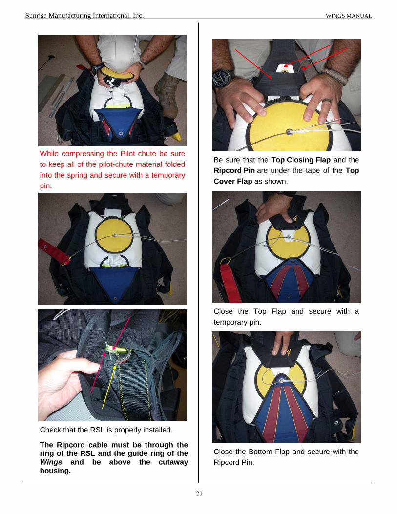
While compressing the Pilot chute be sure
to keep all of the pilot-chute material folded
into the spring and secure with a temporary
pin.
Sunrise Manufacturing International, Inc. WINGS MANUAL
Be sure that the Top Closing Flap and the
Ripcord Pin are under the tape of the Top
Cover Flap as shown.
Close the Top Flap and secure with a
temporary pin.
Close the Bottom Flap and secure with the
Ripcord Pin.
Check that the RSL is properly installed. The Ripcord cable must be through the ring of the RSL and the guide ring of the Wings and be above the cutaway housing.

22
Follow all applicable rules for Documenting
and Sealing the Reserve Container.
RECOUNT THE TOOLS USED DURING
THE PACKING.
The Wings ready for the Main Parachute to be packed.
Sunrise Manufacturing International, Inc. WINGS MANUAL

With no twists in the risers, place the left
front riser line group between the middle and
ring finger of the LEFT hand.
Place the left rear riser group between
the middle and fore finger of the same hand.
Place the control line between the fore
finger and the thumb.
Repeat for the opposite hand and line
groups.
The slider should be between your body
and the parachute.
Walk towards the parachute between the
line groups, moving the slider up the lines
with you and separate the line groups in
your hands.
Upon reaching the parachute, check that
the control lines are not twisted around
any other line groups.
If so, restart this step or perform another
continuity check.
4.3.3 PRO-Pack Method of the
Reserve Parachute.
Follow the instructions for stowing the Reserve
Brake Toggles on page 12.
Step outside of the lines, group the lines
together in one hand and place this group
over your shoulder.
For these instructions, the parachute is
over the left shoulder. Switch orientation if
using the right shoulder.
With the parachute in the correct
orientation (nose towards the container, tail
away from the container) start counting the
leading edge cells out.
Start by slightly turning the parachute
over your shoulder, resting the right outside
cell against your body.
Count each cell and grasp this group.
23
BEFORE PROCEEDING: NOTE THE MAXIMUM OPERATING WEIGHT OF THE RESERVE CANOPY AND MARK ON THE DATA CARD!
Sunrise Manufacturing International, Inc. WINGS MANUAL

24
Push the nose through the center of the parachute and pull it briskly back out. Place the tip of the leading edge between your knees and hold the material in place.
Count and flake the 3 right cells between the C- and D- lines.
Starting with the A-line group, count the 3 right cells between the A- and B- line attachment points and flake the material away from the center of the parachute.
Count the 3 right cells between the B- and C- line attachment points and flake the material away from the center of the parachute.
Count and flake the 3 right cells between the D- lines and the Control Lines / tail.
Repeat this process on the other side of the canopy. Separate the nose, one half on the side, center cell in the middle and second half on the other side.
Raise the canopy so that it is parallel to the floor and gently lay it on the floor.
Sunrise Manufacturing International, Inc. WINGS MANUAL

On the outside folds, smooth out the material between the A-B lines.
25
Pull the slider down and away from the slider stops. Flake the nose cells on one side of the canopy.
Flake the tail of the parachute on top of itself.
After one side is flaked and smoothed out, repeat the other side.
Fold the A-B panels in half to narrow the pack job for the free-bag. Do Not Include the Nose in these folds. Repeat for B-C, C-D panels.
Sunrise Manufacturing International, Inc. WINGS MANUAL
26
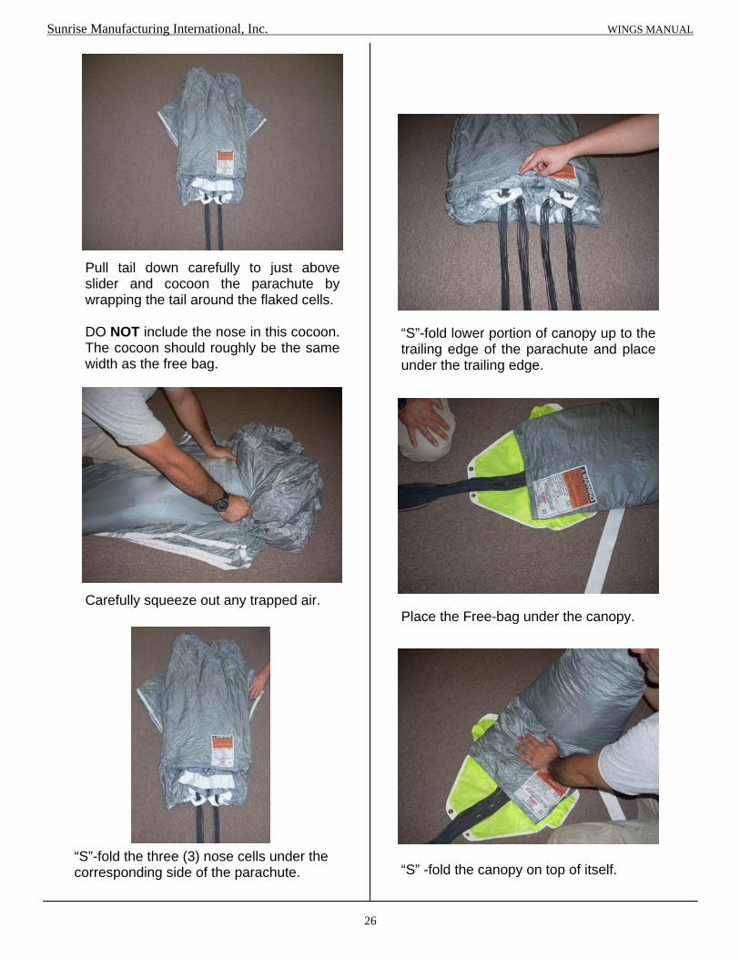
Pull tail down carefully to just above slider and cocoon the parachute by wrapping the tail around the flaked cells. DO NOT include the nose in this cocoon. The cocoon should roughly be the same width as the free bag.
“S”-fold the three (3) nose cells under the corresponding side of the parachute.
Carefully squeeze out any trapped air.
“S” -fold the canopy on top of itself.
“S”-fold lower portion of canopy up to the trailing edge of the parachute and place under the trailing edge.
Place the Free-bag under the canopy.
Sunrise Manufacturing International, Inc. WINGS MANUAL

Fold the canopy back over itself.
Tuck the canopy into the corners of the Free-bag.
Use the Free-bag bridle to hold the safety stow in place.
“S”-fold the canopy over onto itself once again.
Smooth out and make sure that the canopy is no wider than the Free-bag.
27
Sunrise Manufacturing International, Inc. WINGS MANUAL

28
Grasp “ear” and “S”-fold it on top of itself.
Roll the center material to the depth of the Free-bag. Place your knee on to hold in place.
Place into the Free-bag. Repeat the other side “ear”. Straighten and smooth out the “ear”
formed after following the center seam.
Follow the center seam to the end.
Sunrise Manufacturing International, Inc. WINGS MANUAL

29
Fold the Free-bag over the canopy in order to close with the safety stow.
Use two (2) line bights @ 1 1/2” -2” to secure the Free-bag closed.
Begin to stow the rest of the reserve parachute lines into the pocket on the Free-bag.
Open up the Reserve Container. Check to be sure that the Reserve Static Line is installed correctly. If using a M.A.R.D. “Reserve Boost” be sure that you are using a M.A.R.D. “Reserve Boost” RSL and that the Reserve Ripcord cable passes through the middle ring of the RSL.
Alternate back and forth until lines are into the pocket and Reserve Risers are to the Free-bag.
Sunrise Manufacturing International, Inc. WINGS MANUAL

30
Thread a pull-up cord through the closing loop and the center grommet of the Free-bag.
Carefully lift the Free-bag. Check to be sure that the AAD cutter is installed correctly and that the closing loop goes through the cutter.
Flip the Free-bag over to the bottom of the Reserve Container. Do NOT twist the lines.
Sunrise Manufacturing International, Inc. WINGS MANUAL
Use a knee to form a “nest” for the Reserve Pilot chute Spring.

31
Tuck the anti-twist flap under the Free-bag.
Bring the Bridle towards the bottom of the
Reserve Container.
“S”-fold the Bridle into 6”-8” folds (depends
on the width of the Free-bag) leaving about
3’ of Bridle remaining.
Sunrise Manufacturing International, Inc. WINGS MANUAL
Tuck the folded Bridle under the Side Flaps.
Do NOT tuck more than 1” on each side.
Close the Left Side Flap then the Right
Side Flap.
Secure with a temporary pin.
“S”-fold the remaining Bridle as shown.
Pull the pull-up cord through the pilot chute.

32
While compressing the Pilot chute be sure
to keep all of the pilot-chute material folded
into the spring and secure with a temporary
pin.
Sunrise Manufacturing International, Inc. WINGS MANUAL
Be sure that the Top Closing Flap and the
Ripcord Pin are under the tape of the Top
Cover Flap as shown.
Close the Top Flap and secure with a
temporary pin.
Close the Bottom Flap and secure with the
Ripcord Pin.
Check that the RSL is properly installed. The Ripcord cable must be through the ring of the RSL and the guide ring of the Wings and above the cutaway housing.

33
Follow all applicable Rules for Documenting
and Sealing the Reserve Container.
RECOUNT THE TOOLS USED DURING
THE PACKING.
The Wings ready for the Main Parachute to be packed.
Sunrise Manufacturing International, Inc. WINGS MANUAL

34
4.3.4 Closing with the M.A.R.D.
“Reserve Boost” RSL.
Sunrise Manufacturing International, Inc. WINGS MANUAL
Tuck the folded Bridle under the Side Flaps. Do NOT tuck more than 1” on each side. Keep the Bridle to the left side of the center of the Free-bag.
Bring the Bridle towards the bottom of the Reserve Container. “S”-fold the Bridle into 6”-8” folds (depends on the width of the Free-bag) to the “Reserve Boost” modification. Fold the Bridle back towards the top of the container.

35
“Arm” the M.A.R.D. “Reserve Boost” at this time by passing the Spectra Line Loop down through the #0 grommet.
Pass the Spectra Line through the mini ring of the M.A.R.D. “Reserve Boost” RSL.
Loop the Spectra Line back up through the #0 grommet of the Bridle.
Sunrise Manufacturing International, Inc. WINGS MANUAL
Slide the Long Pin through the loop then stow into the channel under the tuck tab channel. Be certain that it is in its own channel.
Tuck the stiffened T-III Tab into the tuck channel on top of the Long Pin Channel.

36
Stow the Spectra Line Loop into the looped polyester sleeve opposite the long pin channel.
Should look like this.
Sunrise Manufacturing International, Inc. WINGS MANUAL
Pull the pull-up cord through the Pilot chute.
Take up the slack of the Spectra Line Loop. Tuck any excess RSL into the channel pocket on the top left side of the free-bag. The M.A.R.D. “Reserve Boost” is armed. Continue to close the Reserve Container.
Close the side flaps. Secure with a temporary pin.

37
Sunrise Manufacturing International, Inc. WINGS MANUAL
Center the Pilot-chute over the Side Flap grommets.
While compressing the Pilot-chute be sure to keep all of the pilot-chute material folded into the spring and secure with a temporary pin.
Make sure the Top Closing Flap is under the retaining tape of the Top Pin Cover Flap. Close and secure with a temporary pin.
Close and secure the Bottom Closing Flap with the Reserve Ripcord Pin.
Follow all applicable rules for Documenting and Sealing the Reserve Container. COUNT THE TOOLS USED DURING PACKING.

38
Sunrise Manufacturing International, Inc. WINGS MANUAL

1
5.1 Main Parachute Inspection
Links should be: Clean of corrosion, debris and without cracks or visible damage. No sharp or raw edges. Free moving barrel, which should be able to tighten 2 ¾ turns from first
engagement of the barrel without resistance.
Rapide Link Covers Covers should be firmly seated on top of links. Covers tacked in place to prevent slippage.
Lines No excessive fraying or damage to lines. Continuity is correct. Bar tacks sewn correctly on each line. Each line is without twists and correctly installed from link to parachute,
passing through correct slider grommet.
Slider Slider is without holes, burns or other damage. Reinforcement tape in place and secure. Grommets seated correctly without burrs or damage.
Bottom Skin Inspect each cell for any tears, fraying or other damage. Seams and attachment points stitched correctly and evenly.
Ribs Cross ports without damage. Stitching correct on seams. Reinforcing tape present on loaded ribs. No other damage on entire rib section.
Top Skin Seams are sewn correctly. Leading edge bar tacks are in place. Control line attachment points are reinforced.
Stabilizers
Slider stops are present and secured. Lines bar tacked to lower edge of stabilizer. Slack is present in stabilizer when line is taut.
Sunrise Manufacturing International, Inc. WINGS MANUAL
Chapter 5
Main Parachute

2
After inspecting the Parachute and the Wings
Harness/Container System, hang or lay the
parachute out on the ground with the nose
section on the ground and the Wings Harness/
Container System oriented face down.
When using Rapide links, check to see that
bumpers have been installed. See pg.3 for
instructions on bumper installation.
5.2.1 Assembly of Main Canopy.
Fold the ends of the risers to narrow the top
section. Maintain line continuity and place the
link of the Right Front line-set onto the end of
the Right Front Riser.
Tighten the barrel finger tight and then an
additional ¼ turn with a small wrench until the
link is tight. Pull the Bumper down and secure
as per the instructions on pg. 3 of this chapter.
Begin the assembly process by ensuring that all
lines are connected to the links correctly with
the Outboard “A”-lines on the outside of the link
and the Center “A”-line towards the inside of the
link, the longer side of the link towards the riser.
Once the continuity of the lines is set, ensure
the slider is correctly oriented; the slider should
be longer span-wise than chord-wise, with the
reinforcing tape of the slider on the side facing
the main parachute.
Inboard “A” line
Outboard “A” line
Sunrise Manufacturing International, Inc. WINGS MANUAL
Right Front Riser Left Front Riser Inboard “A” line
Outboard “A” line
Repeat these steps for the two Rear Risers,
ensuring that the Outboard “C” line is on the link
first.
5.2 Assembly Instructions
Assembly of Main Canopy using Rapide Links.

3
Installing the Slider Bumpers.
With the line group correctly assembled onto the link, run a short piece of line through the closed link and the center of the bumper.
Pull the link through the bumper without twisting or turning the link.
Fold the top of the riser and install the link. Tighten the barrel of the link. Ensure continuity of the line group.
Cinch the bumper over the link and tack into place. The tacking should go through both sides of the bumper and include a surgeon’s knot and locking knot. Once tight, cut the loose ends of the tacking thread.
Sunrise Manufacturing International, Inc. WINGS MANUAL
Follow these instructions when using Rapide links for the Reserve Parachute.

4
Always Read and Follow the Instructions
provided by the Soft Link manufacturer.
Assembly of Main Parachute using Soft Links.
Sunrise Manufacturing International, Inc. WINGS MANUAL
Pass the lead of the Soft Link through the
lines again.
Depending on the Soft Link Manufacturer you
may have to pass it through the Main Riser
and the lines once or twice again.
Follow the manufacturer’s instructions.
While keeping the continuity of the lines in
order pass the Soft Link through each line.
Fold the end of the Main Riser as shown.
Pass the Lead of the Soft Link through the
Riser.
After passing the Soft Link through the lines
and the Main Riser the proper number of
times, pass the Soft Link lead through the
loop of the other end of the Soft Link.
LOOP LEAD

5
Should look like this.
Sunrise Manufacturing International, Inc. WINGS MANUAL
Tuck the Loop and Lead ends under the
Main Riser.
A hand-tack may be used to secure it under
the Main Riser.
Pass the Ring through the Lead then tighten
the knot formed

Pass the loop of the Control Line over the bottom of the toggle.
6
5.3 Installing the Main Steering
Toggles onto the Control Lines.
Tighten the loop up to the grommet. Repeat for the other toggle. The parachute brakes are now ready to be stowed.
Feed the Control Line through the rear of the toggle.
Once the Main Parachute is assembled
onto the Main Risers, feed the Control Line
through the appropriate slider grommet and
guide ring on the Main Riser.
Sunrise Manufacturing International, Inc. WINGS MANUAL

7
5.4 Attaching the Deployment Bag to the Canopy.
Open the Rapide Link of the Deployment Bag and place over the ring of the Main Canopy. Make sure that the security line and kill-line are straight and not tangled.
Sunrise Manufacturing International, Inc. WINGS MANUAL
The Deployment Bag is now attached and ready to have the rubber bands or tube stows attached. Use the correct size rubber band or tube stow as per the canopy manufacturer’s instructions.
Tighten the Rapide Link finger tight then use a small wrench to turn the barrel 1/4 turn. Do NOT over-tighten the link.

8
5.5 Installation of the Main Canopy
Release Handle.
Inspect the ends of the yellow cables of the Release Handle for sharp edges. Ends should be smooth so as to not snag the Type IIA line loop of the risers.
Begin by feeding the shortest yellow cable into the short cutaway housing.
Feed the other yellow cable into the other cutaway housing.
Mate the Hook Velcro of the Main Canopy Release Handle to the Pile Velcro in the pocket on the Right Main Lift Webbing.
Sunrise Manufacturing International, Inc. WINGS MANUAL

9
5.6 Attaching the 3-Ring Risers.
Pass the large ring of the Riser through the large ring of the Harness.
Pass the small ring of the Riser through the large ring of the Riser.
Pass the Type IIA loop through the small Riser ring and into the grommet.
Sunrise Manufacturing International, Inc. WINGS MANUAL
From the back side of the Riser, feed the loop through the housing grommet. Feed the yellow cable through the loop.
Attach the Shackle to the Reserve Static Line (RSL) ring.
CAUTION: Be sure that the loop goes through only the small ring.
Stow the yellow cable into the channel on the backside of the Riser.

10
5.7 Stowing the Main Steering Toggles.
Begin by pulling the steering line until the “cat’s eye” is just through the guide ring.
Tuck the toggle into the elastic keeper.
Sunrise Manufacturing International, Inc. WINGS MANUAL
Pass the toggle through the “cat’s eye” of the steering line.
Stow the excess brake line under the elastic keeper.
Tuck the toggle tail into the elastic keeper.

11
5.8 Flat Pack Method of the Main
Parachute.
Read and follow the instructions for
stowing the Main Steering Toggles on
pg 10.
Grasp the rear line and control line groups
in the LEFT hand and the front line groups
in the RIGHT hand.
Walk towards the parachute, leaving the
slider at the top of the risers, separating the
line groups as you go.
Once at the stabilizer edge, shake the
parachute from side to side.
While maintaining control of the line groups,
lay out the parachute in front of you and
away from the harness/container assembly.
Maintaining line tension will help in later
steps. With tension on the A- and B-line groups, fold the B- line section on top of the A-lines.
With tension on the A-line groups, fold the leading edge under the A-line group.
Walk to the top of the canopy and: Count and flake out the cells leading edges. Count and flake out the B-line seams. Count and flake out the C-line seams. Count and flake out the D-line seams. Count and flake out the control lines and the remainder of the trailing edge of the canopy.
Sunrise Manufacturing International, Inc. WINGS MANUAL

With tension on the B- and C-line groups, fold the C- line section on top of the B-lines.
With tension on the C- and D-line groups, fold the D- line section on top of the C-lines.
Place the control line group on top of the line groups.
Separate the tail section, place the right control lines and material on the right side of the pack job, and the left control lines and material on the left side of the pack job. Bring the slider up to the slider stops and quarter the slider. Fold the material between the control lines out and away from the center of the pack job.
While keeping the control lines in the center of the pack job, begin wrapping the tail around the canopy. Make sure to include the slider.
12
Follow the instructions on page 10 for stowing the Main Steering Toggles.
Sunrise Manufacturing International, Inc. WINGS MANUAL

13
Compress the air out of the parachute and continue cocooning the canopy until it is slightly wider than the deployment bag.
Start “S”-folding the parachute. The first “S”-fold should be approximately 1/3 of the canopy material.
Fold the remaining material on top of the first “S”-fold.
If using a Collapsible Pilot
Chute “cock” the system now.
Sunrise Manufacturing International, Inc. WINGS MANUAL
Pull the pilot-chute handle until you see the mark in the window and the line is taut.
Cock the pilot-chute before placing into the Deployment Bag. While placing a foot on the bridle near the top of the canopy, hold the pilot chute handle or hacky firmly and pull until the slack has been removed from the bridle and the pilot chute is extended to the length of the inside 3/8” tape.

14
Stow the 3rd and 4th line bights using the remaining two grommet stow bands.
Continue stowing the lines, alternating back and forth, until approximately 12” remain.
Sunrise Manufacturing International, Inc. WINGS MANUAL
With the lines from the center of the folded canopy, Stow the first line bight through either of the center grommet stow bands. Stow another line bight through the other center grommet stow band.
Bring the lines up through the center of the canopy and out of the Deployment Bag.
Insert the other corner of the canopy into the other corner of the Deployment Bag.
Place one corner of the canopy stack into the Deployment Bag.

15
Lay the Main Risers into the trough beside the Reserve Container. Be sure to place the Main Risers on top of the Reserve Riser cover flap as shown.
Tuck the Riser Cover into the pocket as shown.
Sunrise Manufacturing International, Inc. WINGS MANUAL
Open the Main Container and check for debris, twigs and pebbles. Attach the Pull-up Cord to the Closing Loop from the #0 grommet at the top of the Main Container.
Lift the Main Deployment Bag over the container without twisting the lines and place into the Main Container with the lines towards the Bottom Flap of the container and the Bridle towards the Reserve container.

16
Close the Left Side Flap.
Close the Right Side Flap.
Pull the closing loop through the Top Main Flap grommet.
Sunrise Manufacturing International, Inc. WINGS MANUAL
Secure with the Closing Pin.
BOTTOM
TOP
RIGHT
LEFT
Close the Pin Protector Flap and tuck the pilot chute bridle under the Right Side Flap as shown.
With the Bridle placed at the top right corner, close the Bottom Main Flap over the D-bag and feed the closing loop through the grommet of the Main Bottom Flap.

“S”-fold the bridle on top of the folded pilot chute.
17
Fold the Pilot chute in 1/2 with the bridle coming out of the middle.
Sunrise Manufacturing International, Inc. WINGS MANUAL
Fold the Pilot chute in 1/2 again with the bridle still coming out of the middle.
Fold the Pilot chute into 1/3’s towards the center.

18
Roll the Pilot chute into a tube shape small enough to fit into the Pilot chute Pocket on the bottom flap.
Insert the Pilot chute into the pocket.
Sunrise Manufacturing International, Inc. WINGS MANUAL
Wings packed and ready to Skydive!
19
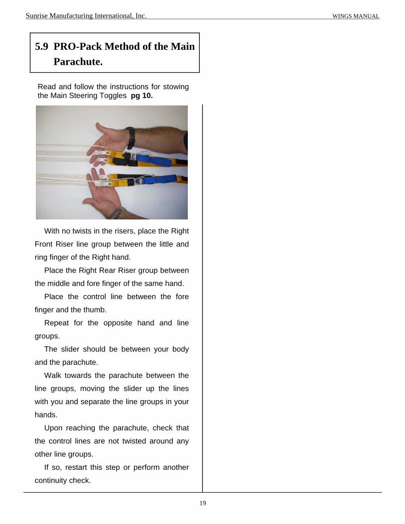
Read and follow the instructions for stowing the Main Steering Toggles pg 10.
With no twists in the risers, place the Right
Front Riser line group between the little and
ring finger of the Right hand.
Place the Right Rear Riser group between
the middle and fore finger of the same hand.
Place the control line between the fore
finger and the thumb.
Repeat for the opposite hand and line
groups.
The slider should be between your body
and the parachute.
Walk towards the parachute between the
line groups, moving the slider up the lines
with you and separate the line groups in your
hands.
Upon reaching the parachute, check that
the control lines are not twisted around any
other line groups.
If so, restart this step or perform another
continuity check.
5.9 PRO-Pack Method of the Main
Parachute.
Sunrise Manufacturing International, Inc. WINGS MANUAL

20
Step outside of the lines, group the lines together in one hand and place this group over your shoulder. For these instructions, the parachute is over the left shoulder. Switch orientation if using the right shoulder. With the parachute in the correct orientation (nose towards the container, tail away from the container) start counting the 9 leading edge cells out. Start by slightly turning the parachute over your shoulder, resting the right outside cell against your body.
Count each cell and grasp this group.
Push the nose through the center of the parachute and pull it briskly back out. Place the tip of the leading edge between your knees and hold the material in place.
Starting with the A-line group, count the 5 right cells between the A- and B- line attachment points and flake the material away from the center of the parachute.
Count the 5 right cells between the B- and C- line attachment points and flake the material away from the center of the parachute.
Count and flake the 5 right cells between the C- and D- lines.
Count and flake the 5 right cells between the D- lines and the Control Lines / tail.
Sunrise Manufacturing International, Inc. WINGS MANUAL

Separate the nose, one half on the side, center cell in the middle and second half on the other side. Quarter the slider by placing the section between the B-C attachment points away from the center of the parachute and separating the front and rear portions in a similar position.
Repeat this process on the other side of the canopy.
Slowly wrap the tail around the line groups. Begin to roll the tail carefully be sure not to disturb the canopy. Keep the roll tight and make enough turns until the top skin appears tight and able to hold the cocoon shape.
Fold the remaining material on top of the first “S”-fold.
21
The first “S”-fold should be approximately 1/3 of the canopy material.
Gently lay the canopy on the floor. Keep the lines tight and do not disturb the pack job. Carefully lay on the canopy to remove as much excess air out of it as possible. Do not allow the canopy to bellow out. After tightening the cocoon to the width of the Deployment Bag, start to “S”-fold the parachute.
Sunrise Manufacturing International, Inc. WINGS MANUAL

22
Cock the pilot-chute before placing into the Deployment Bag. While placing a foot on the bridle near the top of the canopy, hold the pilot chute handle or hacky firmly and pull until the slack has been removed from the bridle and the pilot chute is extended to the length of the inside 3/8” tape.
If using a Collapsible Pilot
Chute “cock” the system now.
Sunrise Manufacturing International, Inc. WINGS MANUAL
Pull the pilot-chute handle until you see the mark in the window and the line is taut.

23
Place one corner of the canopy stack into the Deployment Bag.
Insert the other corner of the canopy into the other corner of the Deployment Bag.
With the lines from the center of the folded canopy, Stow the first line bight through either of the center grommet stow bands. Stow another line bight through the other center grommet stow band.
Stow the 3rd and 4th line bights using the remaining two grommet stow bands.
Bring the lines up through the center of the canopy and out of the Deployment Bag.
Continue stowing the lines, alternating back and forth, until approximately 12” remain.
Sunrise Manufacturing International, Inc. WINGS MANUAL

24
Lay the Main Risers into the trough beside the Reserve Container. Be sure to place the Main Risers on top of the Reserve Riser cover flap as shown.
Tuck the Riser Cover into the pocket as shown.
Lift the Main Deployment Bag over the container without twisting the lines and place into the Main Container with the lines towards the Bottom Flap of the container and the Bridle towards the Reserve container.
Sunrise Manufacturing International, Inc. WINGS MANUAL
Open the Main Container and check for debris, twigs and pebbles. Attach the Pull-up Cord to the Closing Loop from the #0 grommet at the top of the Main Container.

25
Close the Left Side Flap.
Close the Right Side Flap.
Pull the closing loop through the Top Main Flap grommet.
Sunrise Manufacturing International, Inc. WINGS MANUAL
Secure with the Closing Pin.
BOTTOM
TOP
RIGHT
LEFT
Close the Pin Protector Flap and tuck the pilot chute bridle under the Right Side Flap as shown.
With the Bridle placed at the top right corner, close the Bottom Main Flap over the D-bag and feed the closing loop through the grommet of the Main Bottom Flap.

“S”-fold the bridle on top of the folded pilot chute.
26
Fold the Pilot chute in 1/2 with the bridle coming out of the middle.
Sunrise Manufacturing International, Inc. WINGS MANUAL
Fold the Pilot chute in 1/2 again with the bridle still coming out of the middle.
Fold the Pilot chute into 1/3’s towards the center.

27
Roll the Pilot chute into a tube shape small enough to fit into the Pilot chute Pocket on the bottom flap.
Insert the Pilot chute into the pocket.
Sunrise Manufacturing International, Inc. WINGS MANUAL
Wings packed and ready to Skydive!

28
CAUTION: BE SURE THAT THE PILOT CHUTE IS “ARMED” IF IT IS A COLLAPSIBLE PILOT CHUTE!
Close the Top Flap, keeping the Pin and the Handle outside of the container on the lower right.
Follow the Instructions for placing the Deployment Bag into the Main Container and closing the Riser Covers.
Thread the pull-up cord through the closing loop from the #0 grommet at the top of the Main Container. Arrange the bridle into folds 6”-8” long and lay the folded bridle across the upper part of the bag. Be sure NOT to tuck these folds down between the deployment bag and the bottom of the Reserve Container. To do so may retard the action of the pilot chute. Using your pull-up cord, close the Bottom Flap.
Sunrise Manufacturing International, Inc. WINGS MANUAL
Loosely fold the pilot chute and lay it across the D-bag. IMPORTANT!!! THE HANDLE AND THE PIN MUST EXIT THE CONTAINER AT THE LOWER RIGHT SIDE!
5.10 Closing the Main Container
for Pull-out Pilot chute.

Tuck the handle stiffeners into the pull-out pouch folds on the bottom of the Main Container. See Fig. 1, 2, & 3.
29
Sunrise Manufacturing International, Inc. WINGS MANUAL
Fig. 1
Fig. 2
Fig. 3
For tight pack jobs, Tuck BOTH Stiffeners into the Right Side Pouch ONLY.
Always keep these parts on top of the Bottom Closing Flap.

Wings packed and ready to Skydive!
Close the Left Side Flap and secure with the Straight Pin.
30
Sunrise Manufacturing International, Inc. WINGS MANUAL
Tuck the extra Pull-out Bridle under the Right Side Flap.
Close the Main Pin Protector Flap.
Close the Right Side Flap.

Chapter 6
Donning the Wings Harness/Container System
1
IMPORTANT: Inspect the complete system before donning the SMI, Inc. WINGS Harness/Container System.
The WINGS Harness / Container is custom built in a variety of container sizes, lengths, and widths. These configurations along with options make sizing of the harness and container to the individual jumper vital to the safe operation of the system. If the system does not fit properly, the handles may be either inaccessible or may shift in free-fall or under canopy, therefore causing problems that may result in injury or death. The WINGS is designed to fit snugly, yet comfortably, when properly adjusted. A harness that is either too small or too large for the jumper’s body size can affect safety and comfort during a skydive. A Wings dealer is the best person to measure a skydiver for the proper size harness and container.
Every jumper should do a thorough equipment check before every skydive, no matter how experienced the jumper is. Your pre-jump equipment check should follow a logical order.
6.1 Proper Fit of the Wings Harness/
Container System.
Sunrise Manufacturing International, Inc. WINGS MANUAL
6.2 Equipment Check of the Wings
Harness/Container System.
A thorough pre-jump equipment check includes the following checks: 1. Check the Reserve Pin and Cable. The
reserve pin should be straight and seated deep into the locking loop with the end of the pin covered by the pin protection pocket. Slide the reserve ripcord cable back and forth in its housing to ensure that it moves freely. This is especially important in sub-freezing temperatures.
2. Open the Main Container Pin-protector Flap and check the closing pin. It must be at least halfway through the closing loop.
3. Ensure that the Bridle is routed correctly, from the closing pin into the pilot-chute pouch. A misrouted bridle may cause a pilot-chute-in-tow malfunction.
4. Make sure both the Reserve and Main Pin Protector Flaps are tucked into their proper places.
5. If your Wings includes an Automatic Activation Device, calibrate it according to the manufacturer’s instructions.

2
Adjusting the Leg Straps.
6. If using the Reserve Static Line (RSL) be sure that it is properly hooked up.
7. Make sure that the 3-Ring Release System is assembled properly and is free of dirt or other foreign matter.
8. Check the position of the Reserve Ripcord Handle. Make sure that it is properly seated and that the Velcro secures it in its pocket to minimize the chance of it floating or dangling during free-fall.
9. Check the Main Parachute Release Handle (Cutaway Handle). It should be mated to the Velcro on the harness, and no more than 1/2” of yellow cable should be visible between the cutaway handle and the cable housing.
10. Ensure that the Chest Strap is threaded properly and that it is not threaded through the Reserve Ripcord Handle.
11. Ensure that the Leg Straps are threaded properly and not twisted. The free ends of the leg straps should be tucked into the leg pads.
Thread the Chest Strap through the friction adapter. Snug up the Chest Strap but do not over-tighten. The Main Lift Webbing should remain parallel when the chest strap is properly adjusted. Stow the excess in the elastic keeper.
Stow all excess straps in the elastic keepers. Be certain that all Handles are properly seated and accessible.
Sunrise Manufacturing International, Inc. WINGS MANUAL
6.3 Donning of the Wings Harness/
Container System.
Put the rig on and loosely thread the leg straps. Check the leg straps for twists before threading them. Tighten the leg straps so that they are snug, but not so tight that they will restrict mobility in a relaxed arch or turning motion. Make sure that the left and right straps are evenly adjusted. Slide the excess leg strap through the elastic keepers and stow in the leg pads so that they won’t flap around in free-fall.

Chapter 7
Operation of the WINGS Harness / Container System
1
7.1 Deploying the Main Pilot Chute.
Before using the Wings Harness/Container System for the first time, practice the procedures on the ground under the supervision of a knowledgeable Instructor. To deploy the Main Parachute: 1. Find the Pilot chute Handle. 2. Firmly grasp the Handle with the right hand,
while compensating for stability with the left hand.
3. Pull the handle from its pouch and: a. If using a Throw-out Pilot chute, throw the Pilot chute away from the body immediately. or b. If using a Pull-out Pilot chute, pull the Pilot chute out to arm’s length and release into the relative wind. or c. If using a Ripcord, firmly grip the handle and pull down and away from the body to arm’s length.
7.2 Releasing the Main Parachute.
Certain circumstances may require the release of the Main Parachute from the Wings Harness/ Container. Practice these procedures on the ground before boarding the aircraft to skydive. 1. Locate the Main Parachute Release Handle
(Cutaway Handle) on the Right Main Lift Webbing.
2. Grasp the handle and peel in an upward motion.
3. In a swift and smooth motion, pull the Handle down and away from the body to arm’s length.
7.3 Pulling the Reserve Handle.
Sunrise Manufacturing International, Inc. WINGS MANUAL
To deploy the Reserve Parachute: 1. Locate the Reserve Ripcord on the Left Main Lift Webbing. 2. Grasp the handle and peel in an upward
motion. 3. In a swift and smooth motion, pull the Ripcord
down and away from the body to arm’s length.

Chapter 8
Care and Maintenance
1
8.1 General Storage Requirements
To ensure that serviceability standards of the SMI, Inc. WINGS Harness / Container System are maintained, every effort will be exerted to adhere to the following general storage requirements: 1. When available, a climate controlled building should be used to store the WINGS Harness / Container System. 2. The WINGS Harness / Container System shall be stored in a dry, well ventilated location and protected from pilferage, dampness, fire, dirt, insects, rodents and direct sunlight. 3. The WINGS Harness / Container System will NOT be stored in a manner which would prevent ventilation or interfere with light fixtures, heating vents, fire fighting devices, cooling units, exits or fire doors. 4. The WINGS Harness / Container System will NOT be stored in a damaged, dirty or damp condition. 5. The WINGS Harness / Container System will NOT be stored in direct contact with any building, floor or wall. Storage will be accomplished using bins, shelves, pallets, racks or dunnage to provide airspace between the storage area floor and the equipment. 6. Proper housekeeping policies and strict adherence to all safety regulations will be practiced at all times.
In addition to the storage requirements stipulated in the General Storage Requirements, the following is a list of specifics that must be enforced when storing parachutes. 1. Except for those assemblies required for
contingency operations, parachutes will NOT be stored in a packed configuration.
2. Stored parachute assemblies will be secured from access by unauthorized personnel.
3. A parachute that is in storage, and is administered a cyclic repack and inspection, will NOT be exposed to incandescent light or indirect sunlight for a period of more than 36 hours. In addition, exposure to direct sunlight will be avoided entirely.
8.2 Storage Specifics for Parachutes
General Information: 1. An in-storage inspection is a physical check conducted on a random sample of parachutes that are located in storage. 2. Parachutes in storage should be inspected at least once every 180 calendar days and at more frequent intervals if conditions warrant. 3. Inspect the parachute to ensure that it is ready for use. 4. Check to be sure the parachute has the proper identification. 5. Check that no damage or deterioration has incurred. 6. Check the adequacy of the storage facilities, efforts have been taken to control pests and rodents, and protection against unfavorable climatic conditions.
8.3 In-Storage Inspection
Sunrise Manufacturing International, Inc. WINGS MANUAL
5. After the 3rd rinse, allow the equipment to drain thoroughly. Upon completion of draining, dry the equipment by elevating or suspending the item in a well ventilated room or a heated drying room with the temperature not to exceed 130° Fahrenheit or 55° Celsius. When heat is used it shall not exceed 105° F. or 40° C. The preferred temperature is 90° F. / 32° C. The use of electric circulating fans will reduce the drying time.
6. When dried, perform a technical / rigger type
inspection of the equipment. Corroded metal components or corrosion stained fabrics or suspension lines will be either repaired or replaced.
7. Record the immersion and rinsing and any
repairs made to the equipment in the parachute log record.
2
8.4 Water Contamination Guide
If the SMI WINGS Harness / Container or any of its components have been immersed in salt-water for more than 24 hours the equipment will be condemned. If the Harness / Container or any of its components have been immersed in water, be it fresh or salt-water, the Harness / Container and any of the components immersed shall be rinsed immediately or placed in a double plastic bag with the top securely closed to keep the contents in a wet state until they can be rinsed. If they cannot be rinsed within 24 hours, they will be condemned.
! CAUTION !
REMOVE ALL INSTRUMENTS BEFORE RINSING THE HARNESS / CONTAINER AND
THE COMPONENTS.
FOLLOW THESE INSTRUCTIONS FOR RINSING AFTER WATER IMMERSION.
1. Place the equipment in a large container
filled with enough fresh water to completely cover it.
2. Agitate the contents of the container by hand
for 5 minutes. 3. Remove the equipment from the container
and suspend or elevate it in a shaded area for a period of 5-10 minutes to allow it to drain. Do NOT Wring the fabric or suspension lines of a parachute canopy.
4. Repeat the procedures in steps 1, 2 & 3 above,
twice, using fresh, clean water for each rinse.
Sunrise Manufacturing International, Inc. WINGS MANUAL

3
Sunrise Manufacturing International, Inc. WINGS MANUAL

Chapter 9
Special Instructions
1
9.1 Installing the Optional “Reserve Boost”
RSL Extension Lanyard.
Pass the loop of the “Reserve Boost” Extension Lanyard through the ring of the Reserve Static Line.
Pictured above is the “Reserve Boost” Extension Lanyard and the Reserve Static Line.
Sunrise Manufacturing International, Inc. WINGS MANUAL
Pass the ring of the “Reserve Boost” Extension Lanyard through the loop of the lanyard.
Tighten the knot formed. The “Reserve Boost” RSL Extension Lanyard is ready to install on the Wings Container.

2
9.2 Assemble the AFF Left Side Jumpmaster Handle for
Throw-out Pilot-chute.
Follow these Instructions when using the AFF Left Side Main Deployment Handle for throw-out pilot-chute.
Pictured above is the Wings Reserve/Container Assembly with the optional AFF Left Side Main Deployment Handle.
Mate the Pile Velcro of the Pouch to the Hook Velcro of the AFF Left Side Handle.
Sunrise Manufacturing International, Inc. WINGS MANUAL
Pictured above is the AFF Left Side Main Deployment Handle.
The AFF Left Side Main Deployment Pouch before assembly of the Handle.
Begin by mating the Hook Velcro of the AFF Left Side Main Deployment Handle with the Pile Velcro on the Main Container Bottom Flap.

After the Handle has been mated to the Velcro begin to feed the yellow cable of the Handle through the T-III loops on the Bottom Flap of the Main Container and the Spandex Pouch.
3
Sunrise Manufacturing International, Inc. WINGS MANUAL
Alternate passing the cable through the loops of the Bottom Flap and the Pouch.
The AFF Left Side Main Deployment Handle assembled and ready for the Main Container to be closed.
Pass the yellow cable down into the T-III channel in front of the Spandex Pouch opening.
Be sure to include the small loop in the corner of the Bottom Flap.

4
9.3 Closing the Main Container for AFF Left Side Jumpmaster Handle.
Follow the Instructions on pg. 2 to Assemble the AFF Left Side Main Deployment Handle for T/O Pilot Chute.
Follow the instructions for placing the deployment bag into the Main Container and closing the Main Container in Chp. 5.
Pictured above is the Wings Container with the optional AFF Left Side Main Deployment Handle for Throw-out Pilot Chute.
Sunrise Manufacturing International, Inc. WINGS MANUAL
Placing the Throw-out Pilot Chute into the AFF Left Side Jumpmaster Pouch is the same as a standard Bottom of Container Pouch. See Chp. 5.
Once assembled, the AFF Left Side Jumpmaster Handle and Pocket function as a regular BOC.
5
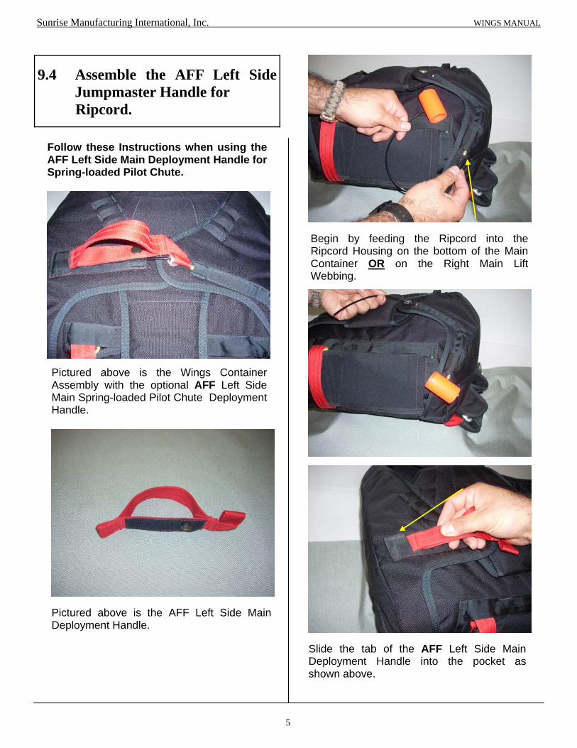
9.4 Assemble the AFF Left Side Jumpmaster Handle for
Ripcord.
Follow these Instructions when using the AFF Left Side Main Deployment Handle for Spring-loaded Pilot Chute.
Pictured above is the Wings Container Assembly with the optional AFF Left Side Main Spring-loaded Pilot Chute Deployment Handle.
Slide the tab of the AFF Left Side Main Deployment Handle into the pocket as shown above.
Sunrise Manufacturing International, Inc. WINGS MANUAL
Pictured above is the AFF Left Side Main Deployment Handle.
Begin by feeding the Ripcord into the Ripcord Housing on the bottom of the Main Container OR on the Right Main Lift Webbing.

6
Follow the Instructions for Closing the Main Container with a Ripcord Assembly pg. 7.
Sunrise Manufacturing International, Inc. WINGS MANUAL
Mate the Velcro of the Handle and the Container then fasten the snap of the Handle to the snap on the Container.
The AFF Left Side Main Deployment Handle ready for closing.

7
9.5 Closing the Main Container with a Ripcord Assembly and the Optional AFF Jumpmaster’s Handle.
Before starting: Assemble the AFF Jumpmaster’s Handle according to the Instructions. Pg. 5. Insert the Black Cable of the Main Ripcord into the Main Ripcord Housing located on the right side of the Bottom of the Main Container OR on the Right Main Lift Webbing.
Pass the Ripcord Cable through the Closing Loop.
Pass the Ripcord Cable through the Loop of the AFF Jumpmaster’s Handle.
Close the Flaps per the Instructions on pg. 8.
Sunrise Manufacturing International, Inc. WINGS MANUAL
RIGHT
Continue to pass the Ripcord Cable into the channel on the Left Side Flap. Close the Main Cover Flap.

8
9.6 Closing the Main Container with a Ripcord Assembly.
Before starting: Insert the Black Cable of the Main Ripcord into the Main Ripcord Housing located on the right side of the Bottom of the Main Container OR on the Right Main Lift Webbing.
Close the Right Main Flap. Then insert the Black Cable through the closing loop. Feed the excess black cable into the channel on the Left Side Flap.
Place the Deployment Bag into the Main Container tray with the Pilot Chute launch pad facing up and the lines to the bottom of the tray.
Close the Left Main Flap.
Use the closing loop mounted to the bottom of the Main Container Flap. “S” fold the Bridle on top of the launch pad.
Sunrise Manufacturing International, Inc. WINGS MANUAL
LEFT
RIGHT
While compressing the Spring-loaded Pilot Chute be sure to keep the pilot-chute material folded into the spring. Close the Top Main Flap.

9
9.7 Closing the Main Container for Spring-loaded Pilot chute Assist
Static-Line.
Pictured above are the two (2) parts of the Spring-loaded Pilot-Chute Assist Static- Line Assembly.
Feed both loops through both loops of the Spring-loaded Pilot Chute.
Begin with the Pile Velcro piece (B) and the smaller loop end of the Pilot Chute Bridle.
Should look like this.
Feed the ends through both of the loops at the same time, forming a double loop. Tighten the formed knot.
Sunrise Manufacturing International, Inc. WINGS MANUAL
B
B
A

10
Next take the Hook Velcro part (A) and the loop of the Static Line.
Feed the Velcro end through the Static Line loop then through the loop of itself.
Tighten the formed Lark’s Head knot. The Spring-loaded Pilot-Chute Assist is ready to be assembled to the Deployment system for closing of the Main Container. Mate the Hook and Pile Velcro of the and proceed to close the Main Container as follows on the next page.
Sunrise Manufacturing International, Inc. WINGS MANUAL
A

11
Set the Deployment Bag into the Main Container Tray, lines to the bottom. Use the closing loop mounted to the bottom of the Main Container Flap.
Compress the Main Pilot Chute.
Pack the Main Canopy using either the Flat Pack method or the PRO Pack method. Follow the instructions for placing the canopy into the Deployment Bag. Chp. 5
“S” fold the Pilot Chute Bridle on top of the Deployment Bag. “S” fold the Static Line Bridle on top of the Pilot Chute Bridle. Lay the Static-line Assist on top of the “S” folds.
Feed the Pull-up cord through the Left Side Flap.
Feed the Pull-up cord through the Top Flap.
Sunrise Manufacturing International, Inc. WINGS MANUAL
LEFT
TOP

12
Close the Right Side Flap and feed one of the black cables through the closing loop. Feed both black cables into the channel shown.
Stow the first bight of the Static Line into the first rubber band.
Stow the remainder of the Static Line into the pocket on the side of the Container.
Continue stowing until last rubber band.
Stow the second bight of the Static Line into the opposite side rubber band.
Sunrise Manufacturing International, Inc. WINGS MANUAL
RIGHT

13
9.8 Closing the Main Container for Throw-out Pilot chute Assist Static Line.
Pictured above is the Throw-out Pilot Chute Assist Static Line Pouch.
Pass the Loop of the Static Line through the Type 4 Loop on the end of the Pilot Chute Pouch.
Pass the rest of the Static Line through the Static Line Loop, creating a Lark’s Head Knot.
Tighten the knot formed.
Sunrise Manufacturing International, Inc. WINGS MANUAL

14
After attaching the Static Line to the Pouch attach the Pilot Chute to the Pouch.
Begin by attaching the tab with the Pile Velcro and the Rapide Link to the Type 3 Loop at the top of the Pilot Chute. Finger tighten plus 1/4 turn with a small wrench.
Mate the Pile Velcro of the tab with the Hook Velcro of the Pouch.
Fold the Pilot Chute in Half.
Fold the Pilot Chute in 1/3’s towards the middle.
Finally roll the Pilot Chute into a narrow roll and place into the pouch, Tab first.
Sunrise Manufacturing International, Inc. WINGS MANUAL
B

15
“S” fold the bridle into 2” folds and place on top of the Pilot Chute in the Pouch.
Close the Flap of the Pouch. Use the rubber band to secure the bridle and keep the Pouch closed.
Set the Deployment Bag into the Main Container Tray, lines to the bottom. Lay the Pouch on top of the Deployment Bag. Use the closing loop mounted on the bottom of the Reserve Container. Close the Bottom Main Flap first.
Close the Top Main Flap.
Close the Left Main Flap.
Close the Right Main Flap. Be sure Static Line comes from the top right side. Insert Black Cable. Stow extra black cable into channel and close Flap.
Sunrise Manufacturing International, Inc. WINGS MANUAL
LEFT
BOTTOM
TOP
RIGHT

16
Stow the first bight of the Static Line into the first rubber band.
Stow the second bight of the Static Line into the opposite side rubber band.
Continue stowing until last rubber band.
Stow the remainder of the Static Line into the pocket on the side of the Container.
Sunrise Manufacturing International, Inc. WINGS MANUAL

17
9.9 Closing for Direct Bag Static-Line.
Begin by attaching the Main Bag to the Static Line.
Pull the red Type 4 Loop that is attached to the inside of the Main Bag through the grommet.
Pass the loop of the Static Line through the red loop of the Main Bag.
Pass the rest of the Static Line through the Static Line Loop, creating a Lark’s Head Knot.
Tighten the knot formed.
Sunrise Manufacturing International, Inc. WINGS MANUAL

18
Pack the Main Canopy using either the Flat Pack method or the PRO Pack method. Follow instructions for placing the canopy into the Deployment Bag. Chp. 5
Set the Deployment Bag into the Main Container Tray, lines to the bottom. Use the closing loop mounted on the bottom of the Reserve Container.
Feed the pull-up cord through the Bottom Flap and pull the closing loop through the grommet. “S” fold the Static Line on top of the Deployment Bag about 12”-16” or to the black cables.
Feed the pull-up cord through the Top Flap and pull the closing loop through the grommet.
Feed the pull-up cord through the Left Side and pull the closing loop through the grommet.
Close the Right Side Flap and feed one of the black cables through the closing loop. Feed both black cables into the channel shown.
Sunrise Manufacturing International, Inc. WINGS MANUAL
LEFT
BOTTOM
RIGHT
TOP

19
Stow the first bight of the Static Line into the first rubber band.
Stow the second bight of the Static Line into the opposite side rubber band.
Continue stowing until last rubber band.
Stow the remainder of the Static Line into the pocket on the side of the Container.
Sunrise Manufacturing International, Inc. WINGS MANUAL

Use a piece of string or 5 cord to pull the elastic band through the washer.
When using Rubber Stow Bands pass the band under the T-4 tape and form a Lark’s Head knot to secure it to the tape.
20
Sunrise Manufacturing International, Inc. WINGS MANUAL
9.10 Using the Optional
Semi-Stowless Deployment Bag.
The Wings Semi-Stowless Main Deployment Bag uses either Elastic Stow Bands or regular Rubber Stow Bands to close the Deployment Bag.
Be sure to have a small washer before the knot to keep the band from passing through the grommet when using the Elastic Stow Bands .
When using Elastic Stow Bands pull them through the #0 grommets using a piece of string or 5 cord thread.

Pack the Parachute in the usual manner and close the Deployment Bag using the same method as a regular Deployment bag.
Follow these Instructions when using the Semi-Stowless Main Deployment Bag.
21
Sunrise Manufacturing International, Inc. WINGS MANUAL
“S-fold” the lines back and forth placing onto the pouch. Leave about 18” unstowed.
The Deployment Bag is ready to be placed into the Main Container.
Open the Line Pouch and fold back the closing flap.
Close the Pouch and tuck the flaps under to secure the lines.

9.11 Stowing the Optional
Swoop Toggles & Risers.
Assemble the Rear Line Sets to the corresponding Rear Riser, (Left side to the Left Riser and the Right side to the Right Riser).
Pass the Steering Line through the appropriate Slider Grommet then through the mini ring closest to the lines.
22
Sunrise Manufacturing International, Inc. WINGS MANUAL
Pass the Steering Line through the rear of the Steering Toggle.
Slip the loop of the Steering Line over the lower tab of the Steering Toggle.
Tighten the knot formed.

Pull the steering line down and pass the “cat’s eye” through the lower mini ring.
23
Sunrise Manufacturing International, Inc. WINGS MANUAL
Pass the Steering Toggle through the “cat’s eye” of the Steering Line to secure the line.
Should look like this. Repeat the other side.
Stow the Toggle Tabs under the Elastic Keepers on the Risers.
Slip the excess loop of the Steering Line under the elastic as shown.

24
9.12 Replacing the Magnets in the Riser Covers.
There are three (3) on each side of the Riser Cover.
Sunrise Manufacturing International, Inc. WINGS OWNER’S MANUAL
Note: When replacing the magnets, be sure that the “A’s” are “attracting” to each other, the “B’s” are “attracting” to each other and the “C’s” are “attracting” to each other and not “repelling” each other. Flip one over to correct the attraction to each other.
The Wings Harness / Container has the options of Magnetic Riser Covers. The Magnets can easily be replaced when needed.
Shown above are the three (3) magnet pockets. The magnets are held in place with Velcro. Slide them out to replace them.
B B
A A
C
C
Shown above is the other side of the Riser Cover. There are three (3) magnets in this pocket also held in place with Velcro. Slide them out and replace.

Chapter 10
Parts List
1
Part # NAME / DESCRIPTION
SRI -100 Standard Wings
SRI -101 Articulated Wings
SRI -103 Articulated Adjustable Student Wings
SRI -104 Standard Wings Vision
SRI -105 Articulated Wings Vision
SRI -106 Articulated FreeFly Wings
SRI -107 Articulated FreeFly Wings Vision
SRI -201 Reserve Pilot Chute
SRI -202 Reserve Pilot Chute Cap
SRI -203 Reserve Free-bag and Bridle
SRI -205 Square Reserve Toggles
SRI -206 Reserve Ripcord Assembly
SRI -207 Reserve Static Line
SRI -209 Pillow Reserve Handle
SRI -210 “Reserve Boost” Free-bag & RSL
SRI- 207A “Reserve Boost” RSL Extension Lanyard
Sunrise Manufacturing International, Inc. WINGS MANUAL

2
Part # NAME / DESCRIPTION
SRI -300 Main Risers Type 8 Lg. Ring
SRI -301 Main Risers Type 8 Mini Ring
SRI -302 Main Risers Type 8 Lg. Ring w/Velcro
SRI -303 Main Risers Type 8 Mini Ring w/Velcro
SRI -304 Main Risers Type 17
SRI -305 Main Risers Type 17 w/Velcro
SRI -306 CRW Main Risers Type 8 SRI -310 Main Steering Toggles (Set of 2)
SRI -311 Main Steering Toggles w/Velcro (Set of 2)
SRI -313 Main CRW Steering Toggles (Set of 2)
SRI -314 Main Release Handle Pillow Style
SRI -315 Main Release Handle Loop Style
SRI -400 Main Spring Pilot Chute w/Bridle
SRI -401 Main Spring Pilot Chute Bridle
SRI -402 Main Spring P/C Bridle/Static-line Assist
SRI -403 Main Standard P/C w/Plastic Handle SRI -404 Main Standard P/C w/Hacky Handle
Sunrise Manufacturing International, Inc. WINGS MANUAL

3
Part # NAME / DESCRIPTION
SRI -406 Main Collapsible P/C w/Bridle & Hacky
SRI -407 Main Collapsible Bridle
SRI -408 Main Standard Bridle
SRI -409 Hacky Handle
SRI -410 Free-Fly Handle
SRI -411 Main Pull-out Handle
SRI -412 Main Static-line
SRI -413 A Pouch for Main S/L Pilot Chute Assist
SRI -413 B T/O PC for Static Line Assist
SRI -414 A AFF Left Side Jumpmaster Handle- T/O
SRI -414 B AFF Left Side Jumpmaster Handle- Spring
SRI -415 AFF BOC Pocket
SRI -500 Main Deployment Bag
SRI -500 A Main Deployment Bag- Semi-Stowless
SRI -500 B Main Deployment Bag Closing Bungee
SRI -600 Main Metal Ripcord Assembly
SRI -601 Main Plastic Ripcord Assembly
SRI -405 Main Collapsible P/C w/Bridle & Plastic
Sunrise Manufacturing International, Inc. WINGS MANUAL

Chapter 11
Spare Parts
1
SRI- 205 Reserve Toggles
SRI- 203 Reserve Free-bag w/ Bridle
SRI- 201 Reserve Pilot Chute
SRI- 202 Reserve Pilot Chute Cap
Sunrise Manufacturing International, Inc. WINGS MANUAL
SRI- 206 Reserve Ripcord Handle
SRI- 207 Reserve Static Line (RSL)

2
SRI- 209 Reserve Ripcord Pillow Style SRI- 304 Main Risers T-17
SRI- 301 Main Risers T-8 Mini Ring
SRI- 210 “Reserve Boost” Free-bag & RSL
Sunrise Manufacturing International, Inc. WINGS MANUAL
SRI- 310 Main Steering Toggles (Set of 2)
SRI- 207A “RESERVE BOOST” RSL EXTENSION LANYARD

3
Sunrise Manufacturing International, Inc. WINGS MANUAL
SRI- 315 Main Release Loop Style
SRI- 412 Main Static-line SRI- 400 Main Spring P/C w/Bridle
SRI- 402 Spring-loaded P/C Parts A & B Static-Line Assist
SRI- 314 Main Release Handle (Red)
A
B
SRI- 406 Main Collapsible P/C w/Hacky

4
Sunrise Manufacturing International, Inc. WINGS MANUAL
SRI- 500 Main Deployment Bag
SRI- 500-A Main Deployment Bag Semi-Stowless
SRI-413 A Pouch / Connector - Main T/O Pilot Chute Static Line Assist
SRI- 413 B Main T/O Pilot Chute Static Line Assist
SRI- 414-A AFF Left Side Jumpmaster Handle T/O Pilot Chute
SRI- 414-B AFF Left Side Jumpmaster Handle Spring loaded Pilot Chute

5
Sunrise Manufacturing International, Inc. WINGS MANUAL
SRI- 500-B Main Deployment Bag Closing Bungee
SRI- 601 Main Ripcord Plastic Handle
SRI- 600 Main Metal Ripcord Assembly

1
NOTES:
Sunrise Manufacturing International, Inc. WINGS MANUAL