wing rear attachment reinforcement - europa aircraft 74.pdf · wing, the pin had not been ... could...
TRANSCRIPT

Wing rear attachment reinforcement
Classification: Mandatory
Applicability: All Europa Classic aircraft fitted with Styrofoam core wings.
Compliance: Within 10 flying hours after August 1, 2007, or before next Permitrenewal, whichever is the sooner.
Introduction
The investigation into the accident with Europa G-HOFC revealed that in the rear attachment of onewing, the pin had not been fitted centrally in the hard-point laminated into the wing root rib for thepurpose. The aluminium strips making up the hard point had also not been fitted directly one in frontof the other, leading to variable edge distance in the tapped hole in the three strips. These featurescould have led to reduced strength in the rear wing attachment.
The design review of the wing rear attachment following the accident encompassed the sockets andthe fuselage where they are mounted. Due to the potential for builder variations of the fuselage sidereinforcement behind the sockets this modification requires that this area of the structure is upgradedto the same standard as the Europa XS and Europa Classic aircraft with Mod 52 (Gross WeightUpgrade to 1370lb) fitted.
This modification introduces a new wing rear-attachment pin with a longer threaded portion and aNyloc nut and load spreading washer added behind the inboard flap hinge-plate to react the tensileload in the pin and so increase the tolerance to incorrectly constructed hard points. In addition, atie-bar is incorporated to efficiently react tensile loads between the wing rear attachments. Thetie-bar forms part of optional Mod 52, however, unless all the other features of Mod 52 are installed,no increase in maximum gross weight will be permitted.
The following description assumes modification to a finished wing and fuselage. It is also assumedthat the following work is to be carried out by the original builder or similarly experienced person. Ifyou are unfamiliar with the techniques required to carry out the work, seek skilled help.
The materials required for this modification are:2 x W24/7 pins2 x M12 Nyloc nuts2 x M12 thick washersSP Systems Ampreg 20 epoxy resin systemInterglass 92125 bi-directional glasscloth (‘bid’) or alternatively XE481 ‘biaxial’ clothFloxMicroStyrofoamPeel-ply
Mod 74 Issue 4 Page 1 of 18

Additionally - for aircraft not fitted with Mod 52.Interglass 92145 uni directional cloth (’uni’)2 x W34 End fittings2 each W35 and W35A Gusset plates1 x W36 Tie-bar tube4 x EUR044 bolts, 4 x EUR046 plain nuts, 4 x MS21042-4 nuts, 4 AN960-4 washers10 each AN3-12A bolts, MS21042-3 nuts, AN960-10 washers1 PLY-12, 16 x 25 x 355mm plywood.1 x EUR049 3mm PVC foam, 250 x 50mm
These materials are available through Europa Aircraft, however, acceptable alternative structuralepoxy resin systems may be used. Some suitable alternatives are Schueffler L285/H286, WestSystems 105/205 and Aeropoxy PR2032/PH3660. The use of materials other than those listed abovewill require approval from Europa Aircraft.
Action
Step 1 – Wing rear pin hole location
The wing rear pin hole is described in the build manual to be located centrally both horizontally andvertically in the hard-point on the wing root rib. Because the metal strips in the hard-point arerelatively narrow, it is important that the hole centre in the horizontal plane is accurate to within1.6mm (1/16”) of the vertical centre of the hard-point. If the hole centre falls outside of thistolerance, contact Europa Aircraft for a repair scheme.
Step 2 – Wing pin removal
Set the wing upside-down,suitably protected againstscratching the paintwork andsteadied against rockingwhilst being worked on.
Before the wing rear pin isremoved, measure and notethe distance from the edge ofthe pip-pin hole to the hardpoint on the root rib (seefigure 1).
This will aid setting up thereplacement pin later.
The pin has been bonded inand will require gentle heat tosoften the adhesive.
Page 2 of 18 Issue 4 Mod 74
Fig 1. Measuring pip-pin hole distance from hard-point

First insulate the rib and wing structure around the pin with wet newspaper or rags then add a heatreflective layer of thin metal or even aluminium foil leaving just the pin exposed through it.
Gently heat just the end of the pin (60°C / 140°F, just too hot to touch, is all that is required) with aheat gun or large soldering iron whilst periodically applying an un-screwing turning force until itstarts to move. A stud remover or pipe wrench will work well for this. Direct the heat gun parallel tothe root rib rather than at it and allow time for the heat to transfer along the pin. Remove the heatsource as soon as it is possible to begin turning it. Take care not to over-heat the fibreglass wing rootrib or surrounding structure as this could lead to delamination damage.
Visually check the threaded hole that there are no signs of it having broken out of the edge of any ofthe three aluminium strips forming the hard point. See figure 2. If it is discovered that the hole doesbreak out of the edge of any of the plates, contact Europa Aircraft for the appropriate repair scheme.
Step 3 – Access to pin threaded end
If necessary for better access, remove the bolts attaching the inboard flap hinge arm to the wingmounted hinge plate and swing the arm out of the way. You will be drilling a 57mm (2 ¼”) diameterhole (small instrument size) in the wing underside, deep enough to gain access to the threaded end ofthe pin. A hole-saw is the ideal tool for this. Make sure that the pilot drill is set only just longer thanthe hole saw itself.
Mod 74 Issue 4 Page 3 of 18
Fig 2. Hidden detail of wing rear attachment hard-point depicting incorrect manufacture

Mark out the centre of the hole according to the drawing in figure 3.
Taking care not to damage the flap hinge plate and the root rib lay-up, cut through the lower skin anddrill down about 3 or 4cm (1-1/2”), remove the piece of skin then dig out the foam down to the depthof the cut. Repeat drilling with the hole saw as necessary until you reach a depth of approximately2cm (3/4”) deeper than the pin hole. Don’t drill any deeper than this and be sure not to allow the pilotdrill to go into the upper skin. You should end up with a neat hole with a flat base.
Now dig a channel in the foam about 4cm (1-1/2”) wide to expose the root rib as shown in figure 3.The edge of the flap hinge plate should be visible through the rib lay-up; check that the washer doesnot overhang the end of the flap hinge plate. If it does, consult Europa Aircraft for advice on how toproceed.
Step 4 – Wing pin installation
Initially, check that the new pins fit the sockets in the fuselage and that the pip-pin can be insertedwithout difficulty.
Carry out a trial installation of the pin in the wing before bonding it in. Screw the pin into the holeuntil the pip-pin hole is the correct distance from the root rib based on your previous measurements.On wings from aircraft that are fitted with Mod 52 – Gross weight upgrade to 1370lb, expect to seeexposed a small length of the pin’s thread. The thread pitch is 1.75mm (0.070”), so each half turn willadjust the hole position by 0.875mm (0.035”). Try both pins in each hole to select the one that bestmatches the original pin hole position; it is quite likely that an exact match will not be achieved.
With the pins installed dry, rig the wings and check that the pip-pin can be installed through both pinand socket together. If you find difficulty in aligning the pin’s pip-pin hole it may save time toremove the pin, file narrow flats (max 3mm / 1/8” wide) for a 9mm or 3/8” spanner, parallel to thepip-pin hole and at the very end of the threaded portion then re-install it.
Page 4 of 18 Issue 4 Mod 74
Fig 3. Dimensions of cavity for access to threaded end of pin
Adjust the wing pin as required for best fit. It may be necessary to apply gentle forward or aftpressure to the wing tip to align the pip-pin holes for pin insertion; this is normal.
Identify each wing pin to ensure that it goes back into the same wing and mark a line on the pin andanother line on the root rib to aid final positioning on reassembly. Noting the number of turnsrequired, remove the pin from the wing.
Ensuring that everything is clean, apply a coat of Loctite 243 onto both the thread of the pin and thatof the hole then screw the pin into the wing to its pre-determined position. With minimum delay, rigthe wing to the fuselage and check that the pip-pin can be inserted. While the Loctite is still setting,the pin can still be turned slightly to correctly align the pip pin hole. Allow the adhesive to curebefore de-rigging to be sure that the pin is not disturbed.
Step 5 – Nut and washer installation
After the Loctite has cured, de-rig the wings and set each of them again upside-down. Mix up a smallquantity of epoxy resin adding flox to make a stiff mix. Apply a generous amount of the flox onto thethreaded end of the pin then install the large washer onto the threaded end of the pin but don’t push ithard against the root rib. The pin and wing root rib are not quite square to each other so the flox isrequired as a ‘liquid shim’.
Screw on the Nyloc nut until just before the edge of the washer contacts the root rib. It is importantthat the washer remains in full contact with the nut and that a wedge of flox remains between it andthe root rib to take up the slight misalignment between the two. Allow to cure undisturbed.
Step 6 – Wing skin repair preparation
The largest ply of the repair lay-up covering the cut away portion of skin will extend onto the wing byat least 125mm (5”), so remove paint and surface filler from the skin for approximately 150cm (6”)around the cut-out where possible. Use 40 grit abrasive paper to provide the appropriate surfacepreparation for bonding.
Carefully sand the skin surrounding the cut-out to taper it down evenly from 45mm (1.75”) out fromthe cut-out edge to reveal the top three plies. You should be able to see faint lines that delineate theplies at 15mm intervals. See figure 4.
Fashion blocks of Styrofoam that will fit into the cavity with as few gaps as possible. See figure 4.
Step 7 - 1st inspection
Before it is covered up, the work including skin preparation must be inspected. An appropriateinspector (PFA in the UK) must check the work done and, if satisfied, an entry must be made in theaircraft logbook. In addition one of the paper placards at the end of this bulletin must be signed anddated by the inspector. The placard is to be placed on the wing root rib after final inspection and thencovered with a single ply of glassfibre with clear resin so that it remains visible.
Mod 74 Issue 4 Page 5 of 18

Step 8 – Foam core replacement
Bond in the foam plugs with epoxy, mixed with micro balloons if available, leaving the foam slightlyproud of the surface.
Note: Don’t be tempted to fill any large gaps with micro. If you do, there is the danger that the blob ofepoxy might exotherm (heat up uncontrollably) due to the insulating properties of the foam. It’sbetter to pack in small pieces of foam instead.
After cure, cut off the excess foam and sand it to be flush with the skin, taking care not to damage theflap hinge plate.
Cut 4 pieces of ‘bid’ (or 2 pieces of ‘biax’) at ±45° per wing measuring 180mm x 180mm (8” x 8”)and 1 piece of ‘bid’ at 45°, measuring 230mm x 230mm (9” x 9”).
Mask the flap hinge plate and surrounding area of wing and flap against resin contamination.
Step 9 - Wing skin repair lay-up
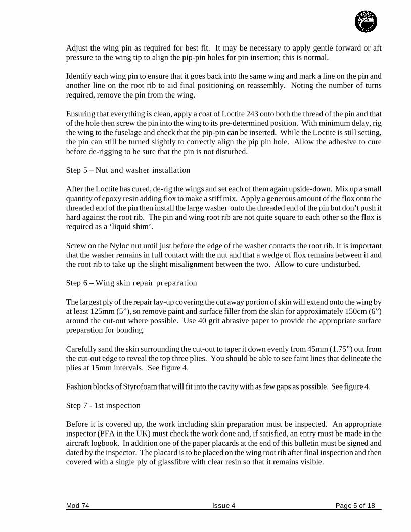
Paint the scuffed area of skin with epoxy resin then apply four plies of ‘bid’ over the foam at ±45° tothe span, lapping the first ply onto the prepared skin by 100mm (4”) where possible and wetting it outfully. Subsequent plies should overlap 15mm less than the previous ply. If using ‘biaxial’ cloth onlytwo plies are laid, the second ply overlapping 30mm less than the first ply. See figure 5.
Page 6 of 18 Issue 4 Mod 74
Fig 4. Skin sanded in preparation for lay-up and foam core pieces made.
Lay-up thefinal ply toextend afurther 2-3cm(1”) beyondthe first ply,then cover theent i re areawith peel-plyand leave tocure.
Aircraft not fitted with Mod 52 –(Gross Weight Upgrade to 1370lb (621kg))
Step 10 - Tie-bar
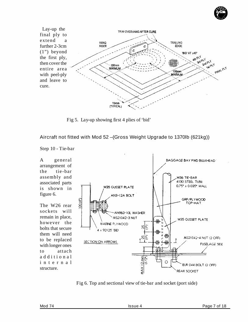
A genera larrangement ofthe tie-barassembly andassociated partsis shown infigure 6.
The W26 rearsockets wil lremain in place,however thebolts that securethem will needto be replacedwith longer onesto at tacha d d i t i o n a li n t e r n a lstructure.
Mod 74 Issue 4 Page 7 of 18
Fig 5. Lay-up showing first 4 plies of ‘bid’
Fig 6. Top and sectional view of tie-bar and socket (port side)

The GRP top-hat stiffener behind each socket is no longer required and a portion needs to be removedto allow access to the nuts that are hidden within it. Cut away as much of the top-hat stiffener aspractical, taking care not to damage the remaining structure, using a saw blade, and finish off with asmall sanding block.
In Tri-gear aircraft, the forward, upper part of the front, outboard main gear support ribs will need tobe cut away locally to give access to the wing rear socket retaining bolts. These ribs and the front,inboard ribs will also need to be cut away locally to allow the tie-bar through.
Remove the nuts from the bolts securing the sockets, but leave the sockets in place on the fuselagesides. The sockets will be held in place only with adhesive, so be careful not to knock them loose.
Mark a centre line across the face of the W34 end fittings then drill one ¼” hole through the flange ofeach, centred ¾” (19mm) from the flange centre. Next locate the W34 in place behind the wing rearsocket using one of the AN4 socket attachment bolts. Rotate it on the bolt until the centre-line alignswith the vacant hole then spot through the hole with a ¼” drill. Remove W34 then drill the secondhole on the bench. Temporarily attach the W34 fitting inside the fuselage using two EUR044 boltsand EUR046 plain nuts for now.
As the fuselage side is at a slight angle to the aircraft centre line where W34 sits, a shim of epoxy andflox will be required on assembly. Take this into account when positioning W34 at this stage. Mark aline across the top of the centre tunnel (and the ribs in Tri-gear aircraft) in the baggage bay torepresent the ¾” diameter steel tube tie-bar which will be fitted between the W34 fittings.
It will be seen that it is necessary to cut a slot in the centre tunnel. Cut this slot and adjust its size toleave a clearance around the tube of approximately 3mm (1/8”).
In Tri-gear aircraft, cut slots in the main gear ribs as required, but rather than a narrow slot as in thecentral tunnel, chamfer the slot sides at a 45° angle where possible. This affords better access for thetie-bar and will make installation of new plywood to reform the ribs easier.
Again, temporarily install the W34 fittings, with the tie-bar and insert the EUR044 bolts in each side.The excess thread on the EUR044 bolts will need to be cut off, but ensure that at least two threadsprotrude through the nut.
Step 11 - Gusset Plates
In addition to reacting the tensile/compressive loads it is necessary to provide sideways stiffness forasymmetric loads. This is done via two plywood blocks laminated onto the baggage bay frontbulkhead, which are connected to the tie bar by means of gusset plates. Refer to figure 6.
Make up two plywood blocks according to figure 7. As each aircraft is bound to be slightly different,the width of the blocks must be determined by measurement.
Page 8 of 18 Issue 4 Mod 74

Scuff sand the bulkhead where theplywood blocks fi t and thesurrounding 5 cm (2”). Using rapidepoxy spread over the entirebonding face, bond the plywoodblock on to the bulkhead, as faroutboard as possible, but allowingspace for the shortened EUR044bolt and aligning it with the tie-bar.Remember to allow 2.5 mm (0.1”)between the block and the tie-barfor the thickness of glass fibrewhich will go over the block.
Once secure, remove the tie-barand W34 fittings and layup four plies of ‘bid’ at ± 45° over the plywood block, lapping onto thebulkhead all around as shown in figure 6. Make fillets with flox in the corners first to prevent theformation of air bubbles. Cover with peel ply and allow to cure.
After cure, remove the peel ply and reposition the tie-bar assembly. Position a gusset plate on top ofthe plywood block and tie-bar such that its outboard edge is no further than 12mm (0.5”) from theflange of W34 and, using the two holes as a guide, drill right through the tie-bar centre-line with a 4.8mm drill. Install an AN3-12A bolt in each hole after drilling to ensure alignment for the next hole.
Now mark a line on the upper gusset plates which is central to the plywood block, then mark thecentres for three holes, each 25mm (1”) apart and 13mm (½”) from the edge of the plate. Drill rightthrough with a 4.8mm drill.
Next, install two W35 gusset plates to each end of the tie-bar, one above and one below, bolting themto the tie-bar with AN3-12A bolts and MS21042-3 nuts with an AN960-10 washer under it. Drillthrough the lower gusset plate with the last 3 holes and install AN3-12A bolts in these also. Don’tadd the nuts to these bolts yet as you’re just about to remove the assembly again.
Step 12 - Final assembly of tie-bar
Initially remove all components identifying where they were fitted for re-assembly. Clean away anyburrs and swarf caused by drilling.
Prepare each side of the slot in the central tunnel of the cockpit module for a glass fibre layup byremoving the upper skin and foam to expose about 10mm (3/8”) of the lower skin. See sectionaldiagram in figure 8.
Mod 74 Issue 4 Page 9 of 18
Fig 7. Plywood block for gusset plates.

The tie-bar can now be installed for the lasttime. For the final installation of the tie-barassembly make a stiff mix of flox and spreadthis on the flat face of the W34 fittings to forma shim to take up the uneven gap between themand the fuselage sides. With the tie-bar inplace, fit the assembly into the fuselage andinstall the EUR044 bolts and MS21042-4 nuts.
Do not tighten the bolts at this point just tightenthem enough to prevent movement of the W34fittings. Scrape away any excess flox fromaround the W34s.
Install the gusset plates with the AN3-12A bolts and MS21042-3 nuts and AN960-10 washers.
Step 13 - Central tunnel slot closure
The final task to be done is to close the slot in the tunnel, tying the tie-bar into it in the process. Cutpieces of 3mm foam to fit into the slot across the top and down the angled side. The side pieces maybe in two pieces each to take it around the tie-bar. Scuff sand the bonding areas each side of the slot.
Layup
Layup 2 plies of ‘bid’ at ± 45° on plastic sheeting at least 30cm x 20cm (12” x 8”). Cut a strip to fitinto the slot and lay it to join the inner skins together. Drape it over the tie-bar, cutting it to allow it togo around the tie-bar at the sides. See figure 9.
Page 10 of 18 Issue 4 Mod 74
Fig 8. Section through baggage bay centre tunnel.
Fig 9. Section through tunnel detailing lay-up sequence.
Apply a layer of flox to the underside of the 3mm foam pieces and lay them in place over the firstlayup.
Next, coat the upper portion of foam with flox and finally layup 2 plies of ‘bid’ at ± 45° over the foamlapping onto the surrounding glass fibre and the tie-bar by about 20mm (3/4”).
Cover with peel ply and allow to cure.
Step 14 - Tri-gear main gear ribs
Using ¾” plywood, make pieces to fit into the ribs where they have been cut away to accommodatethe tie-bar.
Bond these pieces in place using flox then layup over them with 3 plies of ‘bid’ at ± 45° lapping thefirst ply onto the existing ribs by at least 5cm (2”), the subsequent plies being 12mm (½”) shortereach time. Immediately layup 3 plies of ‘uni’ along the top of the ribs and down each side 25mm (1”)with the fibres oriented along the ribs. Overlap the existing ‘uni’ plies by at least 5cm (2”).
All Aircraft
Step 15 - Final inspection
The wing rear attachment modification is now complete and must be inspected before filler and paintis applied. An appropriate inspector must check the work done and, if satisfied, an entry must bemade in the aircraft logbook. In addition, the paper placard for the appropriate wing, signed anddated by the inspector, must be placed on the wing root rib and covered with a single ply of glassfibrewith clear resin so that it remains visible.
Step 16 - Finishing
Apply filler and paint to repair the surface finish according to the Finishing chapter of the EuropaBuild Manual. If re-painting of a large area is required, remove all the previously applied paint tominimise any weight increase.
Check the procedure in your country, but before the modified aircraft may fly in the UK, a PFAinspector must check the work done and, if satisfied, an appropriate entry must be made in the aircraftlogbook and a Permit Maintenance Release (PMR), signed by the inspector.
Mod 74 Issue 4 Page 11 of 18

Appendix 1
Alternative method of accessing the threaded end of the wing pin
Instead of obtaining access from the bottom skin of the wing it is possible to gain access via the flapclose out. Before using this method check that there is at least 1mm (0.040”) clearance between theleading edge of the flap and the flap close out. If this technique is used a ratchet ring spanner will berequired to adjust the nut. When using this method follow the text for the underwing method exceptwhere described below.
Alternative Method - step 3 - Access to pin threaded end
The following text assumes that the wing is positioned leading edge down with the lower portion ofthe flap close out horizontal. Disconnect the flap drive as appropriate for monowheel or trigearaircraft, and swing the flap out of the way.
Referring to figure 10, cut away the skin ofthe flap close-out as marked. Remove theskin on the sloping section first with adremel, and dig out the foam underneathuntil the surface is approximately flushwith the horizontal skin. At this stage use a2 ¼” hole saw and continue the cut 85mm(3 ½”) down. The cut should be angled atapproximately 15° from the verticaltowards the pin - see photo - figure 11.
Next complete steps 4 and 5 on pages 4and 5.
Page 12 of 18 Issue 4 Mod 74
Fig 10. Access hole position in flap close-out.

Dig out the foam as necessary andrepeat drilling with the hole sawuntil approx 20mm (3/4”) past thepin hole.
Alternative method - Step 6 - flap close-out skin repair procedure
Referring to figure 12 and usingthe same technique as in thestandard method, taper the skin.Make and fit foam blocks to fill thehole with as few gaps as possible.
Now complete steps 7 and 8 onpages 5 and 6, but do the repairprocedure according to theAlternative Method - step 9.
Mod 74 Issue 4 Page 13 of 18
Fig 11. Drilling angle.
Fig 12. Foam plug and tapered skins.

Alternative method - Step 9 - flap close-out skin repair lay-up.
Referring to figure 13 layup 3 plies of ‘bid’, lapping the first ply over the skin by 80mm (3 1/4”), thesecond by 15mm (5/8”) less than the first, and the third 25mm (1”) greater than the first. Peel ply allover and allow to cure.
Return to standard underwing instructions, step 10 on page 7..
Page 14 of 18 Issue 4 Mod 74
Fig 13. Repair skins - dimensions

Mod 74 Issue 4 Page 15 of 18

Page 16 of 18 Issue 4 Mod 74

Appendix 2
Mod 74 Issue 4 Page 17 of 18

Page 18 of 18 Issue 4 Mod 74