window performance for human thermal comfort performance for human thermal comfort ... impact on...
TRANSCRIPT

CENTER FOR THE BUILT ENVIRONMENT NOVEMBER 2005
Window Performance for Human Thermal Comfort
Final Report – November 2005
Charlie HuizengaHui ZhangPieter Mattelaer Tiefeng YuEdward ArensUniversity of California, Berkeley
Peter LyonsArup Façade EngineeringMelbourne, Australia
CENTER FOR THE BUILT ENVIRONMENT November 2005
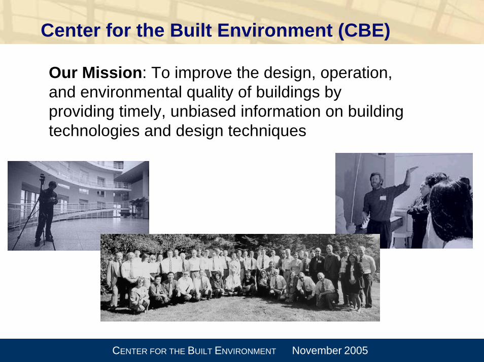
Center for the Built Environment (CBE)
Our Mission: To improve the design, operation, and environmental quality of buildings by providing timely, unbiased information on building technologies and design techniques

CENTER FOR THE BUILT ENVIRONMENT November 2005
CBE Industry Partners
Armstrong World IndustriesArup*California Department of
General Services (DGS)California Energy CommissionCharles M. Salter Associates Flack + KurtzHOKPacific Gas & Electric Co.Price Industries RTKLSkidmore Owings and MerrillStantecSteelcase
Syska Hennessy GroupTate Access Floors*Taylor Engineering Team:
• Taylor Engineering• The Electrical Enterprise• Guttmann & Blaevoet• Southland Industries• Swinerton Builders
Trane U.S. Department of Energy (DOE)*U.S. General Services Administration (GSA)*
Webcor*York International Corporation
*founding partner

CENTER FOR THE BUILT ENVIRONMENT November 2005
CBE research programs
Indoor Environmental QualityEnvelope and Façade SystemsWorkplace DesignUnderfloor Air Distribution (UFAD)Building Information Technology

CENTER FOR THE BUILT ENVIRONMENT November 2005
National Fenestration Rating Council Study
Objective:Develop a technical basis for a method to rate the thermal comfort performance of windows.
Phase I Literature review of thermal comfort studies related to windows, asymmetrical thermal environments, and draft.
Phase II Develop the technical basis and propose a rating method.
CENTER FOR THE BUILT ENVIRONMENT November 2005
Literature review
20 page overview of the literature~175 relevant papers identified~40 papers summarize

CENTER FOR THE BUILT ENVIRONMENT November 2005
How windows influence comfort
Long wave radiation exchange is the dominant mechanism by which windows influence thermal comfort.
Solar radiation absorbed by the window increases the interior window surface temperature. Transmitted solar radiation that reaches the body has a significant impact on comfort.
A cold inside surface temperature can induce a convective draft in a room.

CENTER FOR THE BUILT ENVIRONMENT November 2005
Predicted Mean Vote (PMV) comfort model
The PMV model (Fanger, 1970) is the standard method used to evaluate comfort in buildings.
However, it was based on data from uniform thermal environments (comfort chambers) rather than typical office environments

CENTER FOR THE BUILT ENVIRONMENT November 2005
Local discomfort
Most thermal comfort complaints are a result of local discomfort rather than overall comfort
Windows often cause local discomfort because they affect one side of the body
PMV predicts overall comfort but is not able to assess local discomfort
The CBE model comfort model is able to predict local discomfort
My hands
are cold

CENTER FOR THE BUILT ENVIRONMENT November 2005
UC Berkeley Comfort Model
16 body segments, 4 layers (core, muscle, fat, and skin)
Transient
Blood flow modelHeat loss by evaporation(sweat), convection, radiation, and conductionClothing model (including heat and moisture transfer)
The UCB Comfort Model is a much more sophisticated model that considers non-uniform thermal environments.

CENTER FOR THE BUILT ENVIRONMENT November 2005
UCB Comfort Model interface
The UCB model allows the user to define the 3-D geometry of a room, specify the thermal and solar conditions, define window locations and types, and simulate dynamic comfort response.
The UCB model allows the user to define the 3-D geometry of a room, specify the thermal and solar conditions, define window locations and types, and simulate dynamic comfort response.
CENTER FOR THE BUILT ENVIRONMENT November 2005
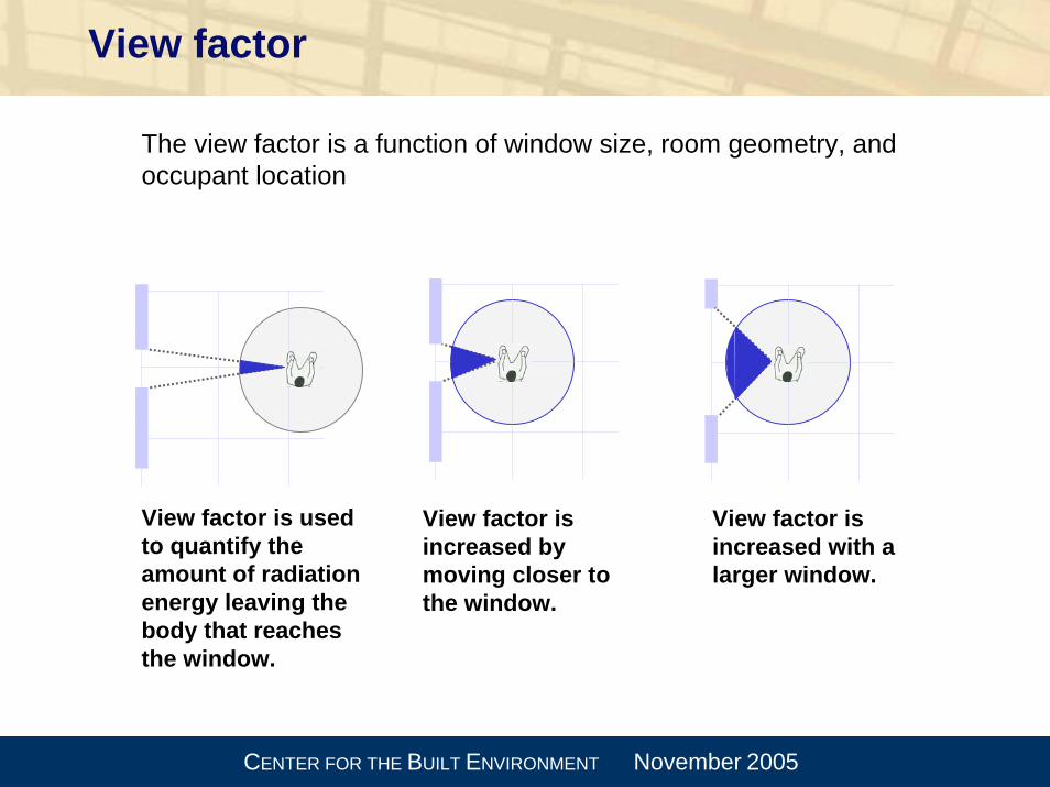
View factor
View factor is increased by moving closer to the window.
View factor is increased with a larger window.
View factor is used to quantify the amount of radiation energy leaving the body that reaches the window.
The view factor is a function of window size, room geometry, andoccupant location

CENTER FOR THE BUILT ENVIRONMENT November 2005
Window to wall ratio (WWR)
WWR=20% WWR=40% WWR=100%
Sample window simulations

CENTER FOR THE BUILT ENVIRONMENT November 2005
Example simulation geometry
•100% Window to wall ratio (WWR)
•Occupant sitting 1 meter from the window
•6m x 6m x 3m room
•Corner office

CENTER FOR THE BUILT ENVIRONMENT November 2005
Window temperature distribution
Center of glass
Edge of glass
Frame
Idealized uniform window temperature
(area-weighted)
Comfort results from area-weighted window temperature are very close to those using actual temperature distribution.

CENTER FOR THE BUILT ENVIRONMENT November 2005
Comparison of PMV and UCB Comfort Model
Sedentary, summer clothing, neutral air temperature, 100% WWR, 1m away from window
-4
-3
-2
-1
0
1
2
3
4
-15 -5 5 15 25 35 45 55 65
Inside Window Surface Temperature
Ther
mal
Sen
satio
n Sc
ale
PMV
very hot
very cold
neutral
5 4123 957759 149131113ºCºF
Sedentary, summer clothing, neutral air temperature, 100% WWR, 1m away from window
-4
-3
-2
-1
0
1
2
3
4
-15 -5 5 15 25 35 45 55 65
Inside Window Surface Temperature
Ther
mal
Sen
satio
n Sc
ale
PMV
UC Berkeley Comfort Model
very hot
very cold
neutral
5 4123 957759 149131113ºCºF
• UCB model more sensitive to warm or cold glass than PMV model
• Can predict local discomfort caused by window
• UCB model more sensitive to warm or cold glass than PMV model
• Can predict local discomfort caused by window
CENTER FOR THE BUILT ENVIRONMENT November 2005
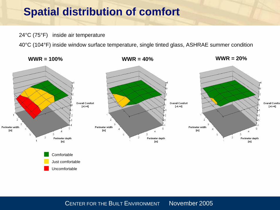
Spatial distribution of comfort
24°C (75°F) inside air temperature
40°C (104°F) inside window surface temperature, single tinted glass, ASHRAE summer condition
Comfortable
Just comfortable
Uncomfortable
WWR = 100% WWR = 40% WWR = 20%
CENTER FOR THE BUILT ENVIRONMENT November 2005
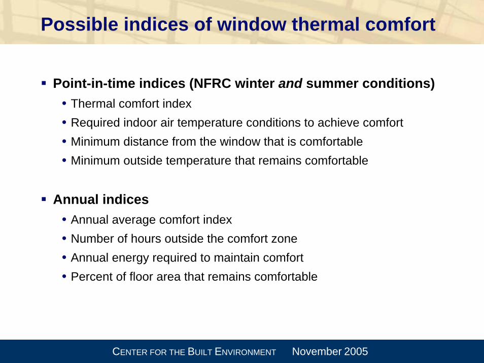
Possible indices of window thermal comfort
Point-in-time indices (NFRC winter and summer conditions)• Thermal comfort index • Required indoor air temperature conditions to achieve comfort• Minimum distance from the window that is comfortable• Minimum outside temperature that remains comfortable
Annual indices• Annual average comfort index• Number of hours outside the comfort zone• Annual energy required to maintain comfort• Percent of floor area that remains comfortable

CENTER FOR THE BUILT ENVIRONMENT November 2005
Comfort vs. interior air temperature100% WWR, office work activity, summer clothing
-4
-3
-2
-1
0
1
2
3
4
18 19 20 21 22 23 24 25 26 27 28 29 30
Interior air temperature
Com
fort
Tglass=30°C
64 817977757372706866 868482ºCºF

CENTER FOR THE BUILT ENVIRONMENT November 2005
Comfort vs. interior air temperature100% WWR, office work activity, summer clothing
-4
-3
-2
-1
0
1
2
3
4
18 19 20 21 22 23 24 25 26 27 28 29 30
Interior air temperature
Com
fort
Tglass=30°C Tglass=10°C
64 817977757372706866 868482ºCºF
CENTER FOR THE BUILT ENVIRONMENT November 2005
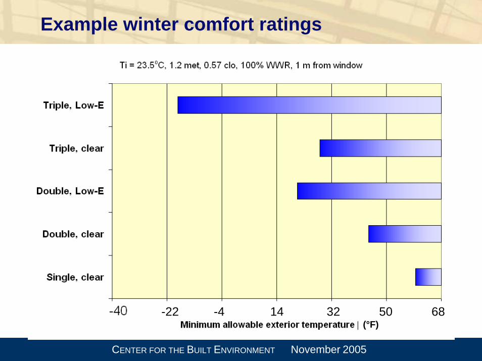
Example winter comfort ratings
32 50 6814-4-22(°F)

CENTER FOR THE BUILT ENVIRONMENT November 2005
Winter rating
factorUFT fthrBtu
−−°=
− 2/83.74min

CENTER FOR THE BUILT ENVIRONMENT November 2005
Recommended U-factors
Zone EnergyStar
Present study(2.5% design DB)
Northern <0.35 0.14 to 0.23
North/Central <0.40 0.20 to 0.28
South/Central <0.40 0.26 to 0.46
Southern <0.65 0.31 to 0.83
U-factors in Btu/h-ft2-F

CENTER FOR THE BUILT ENVIRONMENT November 2005
Winter rating: Annual comfort analysis
0%
10%
20%
30%
40%
50%
60%
70%
0 0.2 0.4 0.6 0.8 1 1.2
U-factor (Btu/ft2-h-°F)
Mpls
Percentage of uncomfortably cool hours vs. U-factor for Minneapolis(1m from 100% glazed façade)

CENTER FOR THE BUILT ENVIRONMENT November 2005
Winter rating: Annual comfort analysis
0%
10%
20%
30%
40%
50%
60%
70%
0 0.2 0.4 0.6 0.8 1 1.2
U-factor (Btu/ft2-h-°F)
MplsDenverBostonSeattleAtlantaSFHoustonMiami
Percentage of uncomfortably cool hours vs. U-factor (1m from 100% glazed façade)

CENTER FOR THE BUILT ENVIRONMENT November 2005
Summer rating
Two major impacts:
1. Inside window surface temperature
2. Transmitted solar radiation(we are assuming no direct solar on the body)
U-factor is relatively unimportant in most cases

CENTER FOR THE BUILT ENVIRONMENT November 2005
Some amount of the diffuse radiation incident on the window is transmitted and a portion of that is absorbed by the person, increasing their thermal sensation.
Impact of diffuse solar radiation
β
dIDHI
dI
CENTER FOR THE BUILT ENVIRONMENT November 2005
Apparent window temperature
Apparent window temperature:
• The temperature of a window in the same environment but without the transmitted solar radiation that would result in thesame thermal comfort as the actual window.

CENTER FOR THE BUILT ENVIRONMENT November 2005
Summer solar rating
Outdoor temperature = 89°F, Solar radiation = 783 W/m2

CENTER FOR THE BUILT ENVIRONMENT November 2005
Inside surface temperature…
Can be predicted using SHGC and Tsol:Qtotal = Qdirect + Qindirect
Direct component of SHGC is Tsol
Indirect component is (SHGC – Tsol) or SHGCindirect
Qindirect = Qsolar*SHGCindirect = hi * (Tinside surface – Tinside air)
Tinside surface = Qsolar* SHGCindirect/ hi + Tinside air

CENTER FOR THE BUILT ENVIRONMENT November 2005
Maximum allowable solar radiation
433
295
470517
1070
455
611
1008
0
200
400
600
800
1000
1200
G1 G2 G3 G4 G5 G6 G7 G8
Max
imum
allo
wab
le s
olar
rad
iatio
n [W
/m²]
Clear, single
Bronze, single
Clear, double
Clear, low-e
double
Selective, low-e
double
Clear, triple
Clear, low-e triple
Selective, low-e triple

CENTER FOR THE BUILT ENVIRONMENT November 2005
Regression of maximum allowable solar
0
200
400
600
800
1000
1200
0 200 400 600 800 1000 1200
Tsol, SHGC based regression
Com
fort
mod
el re
sult
Maximum solar = 1600 W/m2 * (1 – 0.75*Tsol –3.3*SHGCindirect)

CENTER FOR THE BUILT ENVIRONMENT November 2005
Solar Comfort Coefficient
SCC = Tsol + ~5 * (SHGC – Tsol)
Tsol SHGC SCCclear, single 0.77 0.82 1.02bronze, single 0.49 0.72 1.64clear, double 0.61 0.70 1.06low-e, double 0.47 0.59 1.07low-e, selective, double 0.31 0.36 0.56clear, triple 0.49 0.62 1.14low-e, triple 0.34 0.45 0.89low-e, selective, triple 0.25 0.31 0.55