wind turbine electrical system design guide turbine electrical system design guide date created:...
TRANSCRIPT

Wind Turbine Electrical System Design Guide
Date created: 25th July 2008
Version: 1.1
Author: Matt Little
SIBAT, 4th and 5th Floor, 40 Matulungin Street,
Brgy Central, Diliman, Quezon City, Philippines
Phone: (632) 9268971
Telefax: (632) 9288316
Email: [email protected]

ContentsContents .................................................................................................................. 2 Introduction ............................................................................................................. 5 Electrical schematic ................................................................................................ 1 Cable Sizing ............................................................................................................ 3
Voltage drop ........................................................................................................ 3 Cable sizing process ........................................................................................... 4
Oversized cables ............................................................................................ 6 Types of cable ..................................................................................................... 6
Number of strands within cable ....................................................................... 6 Solid core cable ............................................................................................... 7 7 strand cable .................................................................................................. 7 19 strand cable ............................................................................................... 7 Multiple strand cable ........................................................................................ 7 Cable insulation ............................................................................................... 8
Breaker/fuse requirements .................................................................................. 8 Circuit breakers ................................................................................................ 8 Cartridge fuses ................................................................................................. 8 Automotivetype ‘blade’ fuses .......................................................................... 9
Switch ratings .................................................................................................... 10 Energy balance ..................................................................................................... 11 Battery bank .......................................................................................................... 14
System voltage .................................................................................................. 15 Battery bank sizing ............................................................................................ 16
Series and parallel connections ..................................................................... 16 Method 1: Number of days autonomy battery capacity ................................. 16 Method 2: Maximum current battery capacity ............................................... 18 Final battery bank capacity ............................................................................ 19
Battery safety ..................................................................................................... 19 Battery bank practical installation ...................................................................... 20
Good installation practice .............................................................................. 20 Battery disposal ............................................................................................. 22
Battery cable ..................................................................................................... 22 Battery monitoring ............................................................................................. 23 Bus bars ............................................................................................................. 24
Wind turbine electrical system .............................................................................. 25 Wind turbine alternator (PMG) .......................................................................... 25 Wind turbine rectifier .......................................................................................... 25 Wind turbine cable sizing .................................................................................. 25 Wind turbine brake and fuses ............................................................................ 26 Wind turbine grounding ..................................................................................... 27 Lightning protection system ............................................................................... 27
2

Wind turbine monitoring .................................................................................... 28 Ammeter ........................................................................................................ 28 Watthour or Amphour meter ........................................................................ 28
Additional generators ............................................................................................ 30 Cable sizing ....................................................................................................... 30 Breaker ............................................................................................................. 31 Additional load monitoring ................................................................................. 31
Charge controller ................................................................................................... 32 Battery voltage sense ........................................................................................ 33 Charge controller cable sizing ........................................................................... 34 Breaker .............................................................................................................. 34 Dump load ......................................................................................................... 34 Charge controller monitoring ............................................................................. 35
DC loads ................................................................................................................ 36 Cable size .......................................................................................................... 36 Breaker .............................................................................................................. 36 DC load branches .............................................................................................. 37 DC load monitoring ............................................................................................ 38
Ammeter ........................................................................................................ 38 Amphour or watthour meter ........................................................................ 38
AC loads ................................................................................................................ 39 ........................................................................................................................... 39 Inverter ............................................................................................................... 39
Inverter types ................................................................................................. 39 DC cable size .................................................................................................... 42 DC side breaker ................................................................................................. 42 AC cable size ..................................................................................................... 43 AC side breaker ................................................................................................. 43 AC load monitoring ............................................................................................ 44
Current on AC side ........................................................................................ 44 Wh or Ah monitoring on DC side ................................................................... 44 Wh or Ah monitoring on AC side ................................................................... 44 Time run meter .............................................................................................. 45
Other equipment ................................................................................................... 46 System voltage monitor ..................................................................................... 46 Power house lighting ......................................................................................... 49
Design spreadsheet .............................................................................................. 50 Practical issues ..................................................................................................... 53
System layout .................................................................................................... 53 ........................................................................................................................... 54 System grounding .............................................................................................. 54 Cable connections ............................................................................................. 55
Twisted wire ................................................................................................... 55
3

....................................................................................................................... 57 Connector block ............................................................................................. 57 Bolted ring connectors ................................................................................... 59 Water proof connections ................................................................................ 61
Long distribution cables ..................................................................................... 63 1.Low voltage DC cable ................................................................................. 64 2.High voltage DC cable ................................................................................ 65 3.Low voltage AC cable ................................................................................. 65 4.High voltage AC cable, powerhouse near load .......................................... 65 5.High voltage AC cable, powerhouse near wind turbine ............................. 66 Recommendations ......................................................................................... 66
Generators ......................................................................................................... 66 Electrical integration ...................................................................................... 67 Control strategies ........................................................................................... 68 Recommendation ........................................................................................... 71
Appendices ........................................................................................................... 72 Renewable energy suppliers in the Philippines ................................................ 72
4

IntroductionThis is a guide to the various features and considerations required for designing an electrical system for a small wind turbine.
It has been written specifically for implementing the 1kW version of a wind turbine design from Hugh Piggott. The turbine is described in detail in his ‘How to build a wind turbine: the axial flux windmill plans’ guide, available from http://www.scoraigwind.com/, although the information here is relevant to any small wind turbine system.
This guide was produced for SIBAT, an NGO based in the Philippines, who are implementing the 1kW (1.8m blade) small wind turbines for use in remote areas of the Philippines.
The additional documents which are used along with this guide are:
•Electrical schematic (AutoCAD file)
o ‘WT_Model_Electrical_System.dwg’
•Design spreadsheet (Excel file)
o ‘WT_System_Sizing_Final.xls’
Note: This is a guide only – careful consideration must be given to all aspects of the electrical design for a specific application. Electrical systems can be very different depending upon the generators and the loads they supply.
Note: Electricity can be very dangerous. Please consult a qualified electrical engineer before implementing any systems.
Documents required before using this guide:
Load assessment:
Wind resource assessment:
Other resource assessment (solar, generator, etc.):
Note: Please email the author (matt@re innovation.co.uk ) if you have any comments and suggestions.
5

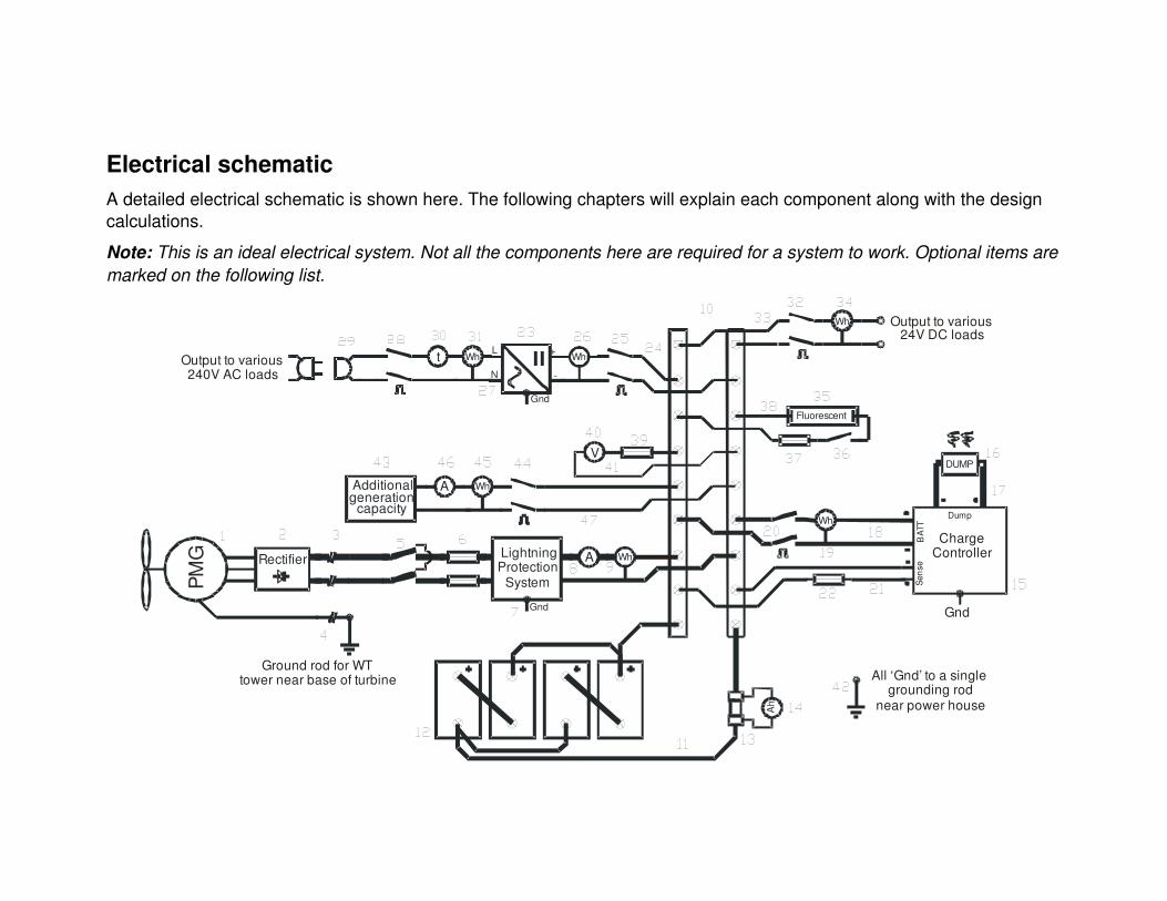
Electrical schematicA detailed electrical schematic is shown here. The following chapters will explain each component along with the design calculations.
Note: This is an ideal electrical system. Not all the components here are required for a system to work. Optional items are marked on the following list.
Additionalgeneration
capacity
A
Wh
L
Gnd
N
+
DUMP
Wh
Wht Wh
Fluorescent
V
Ah
LightningProtection
System
Gnd
Rectifier
PMG WhA
Ground rod for WTtower near base of turbine All ‘Gnd’ to a single
grounding rod near power house
Output to various240V AC loads
Output to various24V DC loads
Wh
Gnd
Sens
eB
ATT
ChargeController
Dump

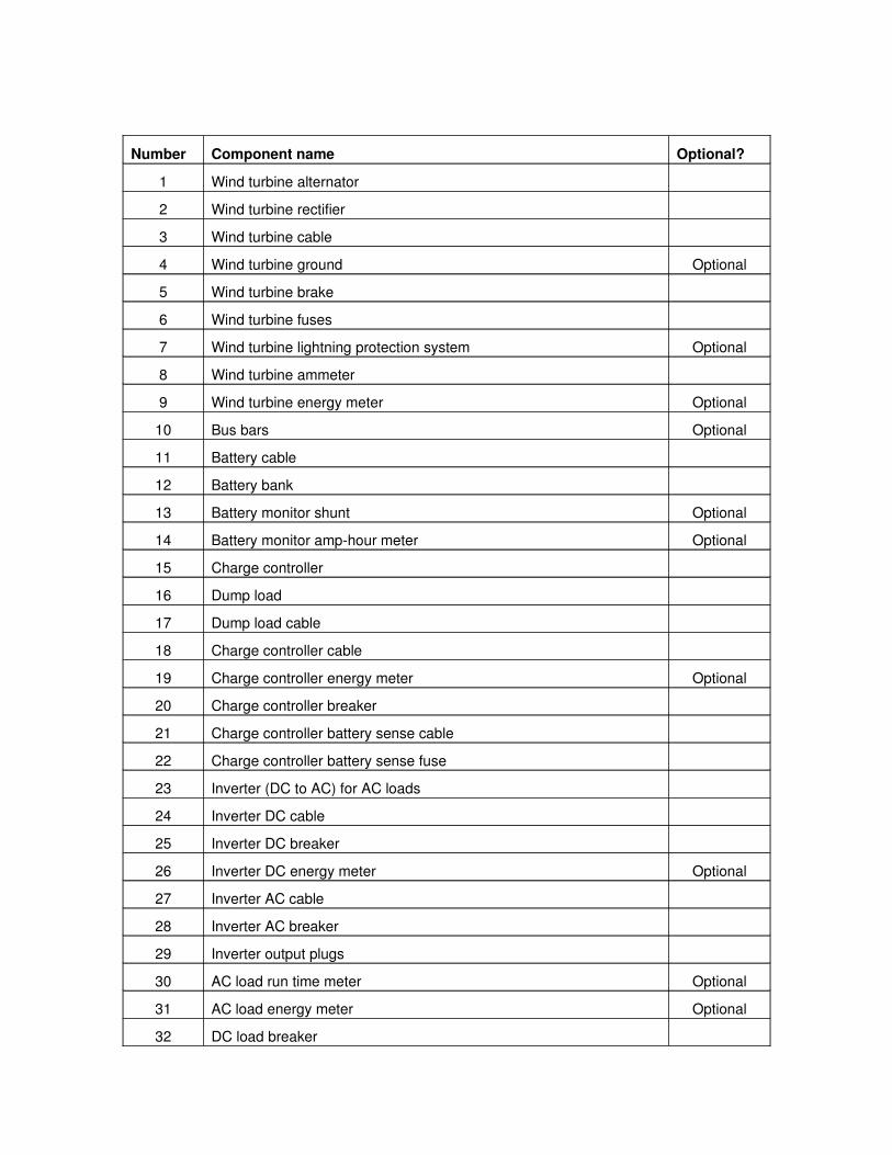
Number Component name Optional?
1 Wind turbine alternator
2 Wind turbine rectifier
3 Wind turbine cable
4 Wind turbine ground Optional
5 Wind turbine brake
6 Wind turbine fuses
7 Wind turbine lightning protection system Optional
8 Wind turbine ammeter
9 Wind turbine energy meter Optional
10 Bus bars Optional
11 Battery cable
12 Battery bank
13 Battery monitor shunt Optional
14 Battery monitor amphour meter Optional
15 Charge controller
16 Dump load
17 Dump load cable
18 Charge controller cable
19 Charge controller energy meter Optional
20 Charge controller breaker
21 Charge controller battery sense cable
22 Charge controller battery sense fuse
23 Inverter (DC to AC) for AC loads
24 Inverter DC cable
25 Inverter DC breaker
26 Inverter DC energy meter Optional
27 Inverter AC cable
28 Inverter AC breaker
29 Inverter output plugs
30 AC load run time meter Optional
31 AC load energy meter Optional
32 DC load breaker

33 DC load cable
34 DC load Watthour meter
35 Power house fluorescent lighting
36 Power house lighting switch
37 Power house lighting fuse
38 Power house lighting cable
39 System voltmeter fuse
40 System voltmeter
41 System voltmeter cable
42 System ground
43 Additional generation capacity (solar PV, generator etc.)
44 Additional generator breaker
45 Additional generator Watthour meter Optional
46 Additional generator Ammeter
47 Additional generator cable
2
Cable SizingOne of the most important aspects of electrical design for low voltage DC renewable energy systems is the correct sizing of cables, switches and fuses. As there are many cables to the different components, the calculations for sizing cables will be repeated many times. This section shows the calculation steps required to correctly size a DC cable at a given voltage and power rating. Also the various types of cable available, along with correct fusing and switch ratings will be discussed here.
Voltage dropAny current flowing along a cable will cause a voltage drop along the cable. The copper conductor within a cable has some resistance and we know that voltage = current x resistance. Hence any current flowing through any resistance (no matter how small) will have a voltage drop.
There are two main problems with this:
• Firstly, there will be an associated power loss, as power = volts x amps. This is usually called ‘copper loss’. This is bad for a renewable energy system, where maximum use should be made of the generated power. Also, the power is lost as heat, which can cause degradation of the cable insulation (which in turn could lead to a short circuit), overheating of equipment and, as a very worst case scenario, fires.
• Secondly, if the voltage drop is too high then some system components will not function correctly. For example, if the voltage drop is 2V in a 12V system, the inverter will only ‘see’ 10V. This is probably below the low voltage cutoff value and hence the inverter will not function.
Due to the relatively low voltages used in batterybased renewable energy systems, coupled with quite high powers, the currents flowing through the cables can be very high. This means that voltage drop can be a very serious problem. Cables should always be correctly sized to ensure a low voltage drop. Typically the cable should be sized to ensure a cable drop of less that 5%, although this must be reviewed in every situation.
The voltage drop can be calculated using the size and length of the cable, the resistance of copper and the current.
Resistance = ( xρ L) / A
Where ρ is the resistivity of copper, L is the length of the cable run and A is the crosssectional area of the copper in the cable.
3

The resistivity of copper ( )ρ is a function of temperature, hence the approximate ambient temperature (tambient) of the system should also be known, along with a resistivity at a known temperature (tknown).
The resistivity at the ambient temperature can then be calculated from the equation:
ρambient = ρknown (1+((tambient tknown) x c )),
where c is a constant which depends upon the conductor material. Usually copper cables are used, in which case c = 0.00323. Once ρambient has been calculated, it can be used for all the cable sizing calculations. A typical value of ρknown = 1.724 x 10⁸ m at 20ºC, hence Ω ρambient = 1.668 x 10⁸ m at 30ºC. In allΩ the equations that follow, the symbol is used to denote ρ ρambient.
The voltage drop in one cable will be:
Voltage drop in a cable = Current x Resistance = I x (( xρ L) / A)
This voltage drop will occur in both cables, i.e. there will be resistance in both the positive and negative cables supplying the device. Hence the total voltage drop is:
Voltage drop, Vd = 2 x Current x Resistance = 2 x I x (( xρ L) / A)
The voltage drop is usually expressed as a percentage of the system voltage:
Voltage drop percentage, Vd_% = (Vd / Vsys) x 100
The above equations can be rearranged in terms of the minimum required crosssectional area, Amin:
Amin = (2 x Imax x xρ L) / ( (Vsys x Vd_%) / 100)
Cable sizing process
1. Choose the nominal voltage of the cable (Vsys).
2. Choose the maximum power to be transmitted along the cable (Pmax).
3. Calculate the maximum current, including a 25% safety factor (Icable = 1.25 x (Pmax/Vsys)).
4. Choose the ambient temperature and hence calculate the resistivity of copper at this temperature ( )ρ .
5. Measure the length of the cable run (L). The actual cable required will be twice this length (two cables required, positive and negative).
6. Choose the maximum allowable voltage drop as a percentage of the nominal voltage (Vd_%). Typically this is 5%.
4

7. Use the equation: Amin = (2 x Icable x xρ L) / ( (Vsys x Vd_%) / 100) to calculate the absolute minimum crosssectional area of the cable conductor (Amin).
8. Depending upon the cable installation method, there may be a derating factor required to stop the cable overheating. The options are:
Installation Method Current Derating FactorFree cable 1
Cable in conduit 0.7
The cable must be larger if it is installed within conduit, hence divide the minimum crosssectional area (Amin) by the derating factor to give the installed minimum crosssectional area, (Amin_inst).
9. This value can then be compared to lists of standard available conductor sizes, both for metric and AWG (American Wire Gauge). Depending upon the available cables, the closest larger value should be chosen.
Standard metric sizes (mm2) Standard AWG cable sizes
AWG Metric equivalent
0.75 20 0.52
1.25 18 0.82
2 16 1.32
3.5 14 2.1
5.5 12 3.3
8 10 5.32
14 8 8.5
22 6 13.5
30 4 21.3
38 2 33.7
50 1/0 (0) 53
60 2/0 (00) 67.6
80 3/0 (000) 84.4
100 4/0 (0000) 107
Note: These are the values for the Philippines, where this guide was written. The standard sizes may be different in other countries.
5

Note: Cables can also be placed in parallel to reach the required conductor size. This could save money if, say, just one size cable is ordered and the larger cables are made from using two pieces in parallel. If this technique is used then the cables should be carefully marked (perhaps taped together?) and be exactly the same length.
10.The cable has now been chosen. It is useful to recheck the maximum voltage drop and power dissipated by the final chosen cable, to ensure the values look reasonable.
Oversized cables
This design process will give the minimum required cable size for the voltage drop. If possible, it is sometimes best to oversize the cable.
The advantages of this include: Minimise voltdrop Less overheating under fault conditions Circuits can be added to without uprating cables (as long as they are still
large enough) Simplifies ordering (whole drums of cable be used for lots of different
circuits)
Disadvantages of oversized cables include: More costly Can be more difficult to run
Types of cableThere are numerous types of cable for use in various installations. The main choices to make are:
•The number of strands in the cable, and
•The type of insulation.
Number of strands within cable
The number of strands affects the flexibility of the cable. A single strand cable will be far less flexible than a cable with 100 strands. Use a cable with as many strands as possible as it is usually more useful to have flexible cable.
6

Solid core cable
Typically cheapest
Will maintain position when installed
Not flexible, especially for thick cables. This makes installation difficult
7 strand cable
Will maintain position when installed
Medium flexibility but still difficult to work with thick cables
19 strand cable
This cable is not shown on the photo above.
Will maintain position when installed
Good flexibility
Relatively expensive and hard to find
Multiple strand cable
Very flexible, even for thick cables (especially welding type cable)
Relatively expensive
Sometimes difficult to attach connectors due to number of strands
Sources of flexible, high current (large crosssectional area) and relatively economical cable include those for automotive electrics and for welding applications.
7

Cable insulation
Cables with many different types of insulation are available. Usually the type insulation does not matter greatly as long as the insulation is rated for the system voltage. UV stable insulated cable should be used for any cable exposed to sunlight, or the cable should be installed within UV stable conduit.
Breaker/fuse requirements
ALL cables should be protected by a fuse or a circuit breaker. This is to protect against short circuits which can damage equipment on the system and can easily cause a fire. When short circuited, batteries can supply incredibly high currents (1000’s of amps).
Types of fuses include (although the range of different sizes and types is incredibly varied):
Circuit breakers
Typically used for the various circuits in a building supply
Available up to medium current ranges
Can be easily reset at no cost
More expensive initial cost
Cartridge fuses
Typically used as the main fuse for AC household supplies (shown here)
Many different types and sizes available
Relatively cheap
8

Must be replaced when they blow
Automotivetype ‘blade’ fuses
Similar to cartridge type fuses but usually used in DC automotive applications
Cheap and readily available
Cheap for medium current ratings
Suitable for low voltage DC systems
Must be replaced when they blow
Typically not manufactured to a good tolerance
Difficult to find fuse holders – perhaps try automotive suppliers
Generally circuit breakers are the best type of fuse to install, if the money is available. It has been noted many times that, when a fuse blows and a replacement fuse is not available, then the fuse is bypassed in some way typically with thick wire or tin foil used to short out the blow fuse. This is very dangerous as the fuse is there to protect the equipment installed. This generally leads to more serious problems. Reasons for doing this usually are lack of funds to buy a replacement fuse and lack of access to the correct fuse (in remote areas).
The rating of the fuse must be 1.25 times the cable current (Icable). This will allow for a safety margin to ensure no nuisance tripping. Ifuse = 1.25 x Icable.
Choose the next standard fuse size above the calculated fuse rating.
Note: The standard fuse ratings in the Philippines are: 15, 20, 25, 30, 35, 40, 45, 50, 60, 70, 80, 90, 100, 110, 125, 150, 175, 200A. Numerous lower rated fuses are usually available. Please check the locally available standard fuse ratings.
The fuse should be fitted as close to the supply (in this case, the battery) as possible in order to protect the whole cable.
Fuses should be fitted in the positive line.
The fuse must be rated for DC current at the correct voltage.
If AC fuses (with no DC voltage rating) are used, then their AC current rating must be either:
•Twice the required DC current value (i.e. Ifuse_AC = 2 x Ifuse), or
•Two AC fuses, rated at the required DC current level, can be used, one in each line, positive and negative (i.e. two fuses or a double pole breaker is required).
This is due to the large spark generated when a DC current flow is broken.
9

Good sources of low voltage DC fuses are automotive shops, which supply 12V DC items for cars and 24V DC items for trucks.
Switch ratingsAny switches in the cable must be rated for the maximum cable current, Icable, and at the correct DC voltage. As with the fuses, if AC ratings are used then the switch must have an AC rating at least twice that of the DC current, or a switch with an AC rating of Icable can be used with both positive and negative lines switched at the same time (i.e. use a double pole switch).
10

Energy balanceFirstly, it is assumed that a load assessment, a wind resource assessment and, if required, additional resource assessments, have already been completed.
The load assessment will yield:
• Daily energy required for the DC loads (Eloads_DC)
• Maximum load demand for DC loads (Pload_DC_max)
• Is an inverter required? (i.e. do some of the loads require an AC supply?)
• If yes, Daily energy required for the AC loads (Eloads_AC)
• Maximum load demand for AC loads (Pload_AC_max)
The wind resource assessment will yield:
• Daily energy from wind turbine at the site (EWT)
• Wind turbine maximum power (PWT)
Note: It is important to carefully consider the daily energy from the wind turbine value used here. The wind resource assessment shows the average daily energy for each month, along with the annual average daily energy. It is important to note the difference between the minimum and maximum monthly energy values – this shows how the resource varies throughout the year. Due to selfdischarge (where the battery will lose charge over a period of weeks), the batteries cannot store energy to smooth out annual variations. If there is a large variation then it would be best to design the electrical system based upon the month with the minimum daily average energy value (rather than the average). This will produce a system design that will work throughout the year, but will be more expensive. If the annual variation is small, then the annual daily average energy value can be used.
This is ultimately a choice for the system designer as it is a trade off between supplying the loads throughout the year and the cost of the system. It may be acceptable to design for the annual daily average value and accept that for some months there will have to be a reduction in energy use. A good starting point would be to design and cost a system for both the annual daily average value and the minimum daily average value. The costs can then be compared to help the designer make their choice.
Some systems may have other generating sources, such as solar PV panels or a diesel generator. If this is the case then additional resource assessments must be performed. These should yield:
•The additional daily energy input from these sources (Eadd)
11

•The maximum additional generator power (Padd).
Note: Again, carefully consider the daily energy value used here. Use the annual average value it the resource does not vary greatly throughout the year; use the minimum value if there is large annual variation.
Obviously the inputs into the system must be equal or greater to the outputs; hence the energy generated by the wind turbine (Ewind) along with any additional energy from other generating sources (Eadd) must be greater than the energy required by the load (Eloads), including any inefficiencies in the electrical system.
Approximate efficiencies of components in the electrical system include:
•Wind turbine rectifier (ηrect) ≈ 98%
•Wind turbine cable copper losses (ηcable) ≈ 95%
•Battery storage (ηbatt)≈ 80%
•Inverter, if used, (ηinv) ≈ 90%
The energy into and out of the system must be balanced, therefore the following equation must be satisfied:
Eloads ≤ Egeneration
Where:
__
(( ) )
loads ACloads loads DC
inv
generation wind rect add cable batt
EE E
E E E
� � � �
� � � � �
Hence:
__ (( ) )loads AC
loads DC wind rect add cable battinv
EE E E
� �
� � � �� �� �
It does not matter if there is too much energy: the system should incorporate a charge controller (see later ‘charge controller’ section) through which any excess will simply be dumped.
Note: Throughout this guide a worked example is followed. This is to give a practical example to highlight all the calculation steps.
Example: The example followed in this guide is for a system to supply:
•Eloads_DC = 1000Wh/day with a maximum DC load of Pload_DC_max = 200W
•Eloads_AC = 2000Wh/day with a maximum AC load of Pload_AC_max = 400W
12

The wind resource assessment gave the following values for the month with the minimum wind resource. These values are used so that the system will be able to supply the loads throughout the year.
•EWT = 3000Wh/day from a wind turbine with a max power of PWT = 1000W
Additional energy comes from a solar photovoltaic (PV) array incorporated into the system:
• Eadd = 1000Wh/day from a PV array of Padd = 380Wp
We must check to see if these values are viable:
Eloads ≤ Egeneration
__ (( ) )loads AC
loads DC wind rect cable add battinv
EE E E
� �
� � � �� �� �
3105 Wh/day ≤ 2994 Wh/day
This is an interesting point where experience plays an important part.
Loads are not ≤ Generation, therefore this system is not viable, but only by a small margin. These values are close enough for us to carry on with a system design. Perhaps, if money is available, additional solar panels could be installed to meet the full load. Otherwise the load could be reduced very slightly.
The total daily load requirement will be used later, Eloads = 3105Wh/day.
13
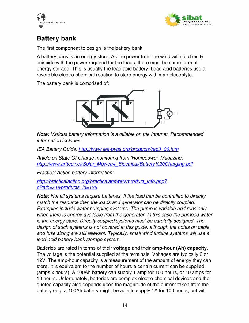
Battery bankThe first component to design is the battery bank.
A battery bank is an energy store. As the power from the wind will not directly coincide with the power required for the loads, there must be some form of energy storage. This is usually the lead acid battery. Lead acid batteries use a reversible electrochemical reaction to store energy within an electrolyte.
The battery bank is comprised of:
Ah
Note: Various battery information is available on the Internet. Recommended information includes:
IEA Battery Guide: http://www.ieapvps.org/products/rep3_06.htm
Article on State Of Charge monitoring from ‘Homepower’ Magazine: http://www.arttec.net/Solar_Mower/4_Electrical/Battery%20Charging.pdf
Practical Action battery information:
http://practicalaction.org/practicalanswers/product_info.php?cPath=21&products_id=126
Note: Not all systems require batteries. If the load can be controlled to directly match the resource then the loads and generator can be directly coupled. Examples include water pumping systems. The pump is variable and runs only when there is energy available from the generator. In this case the pumped water is the energy store. Directly coupled systems must be carefully designed. The design of such systems is not covered in this guide, although the notes on cable and fuse sizing are still relevant. Typically, small wind turbine systems will use a leadacid battery bank storage system.
Batteries are rated in terms of their voltage and their amphour (Ah) capacity. The voltage is the potential supplied at the terminals. Voltages are typically 6 or 12V. The amphour capacity is a measurement of the amount of energy they can store. It is equivalent to the number of hours a certain current can be supplied (amps x hours). A 100Ah battery can supply 1 amp for 100 hours, or 10 amps for 10 hours. Unfortunately, batteries are complex electrochemical devices and the quoted capacity also depends upon the magnitude of the current taken from the battery (e.g. a 100Ah battery might be able to supply 1A for 100 hours, but will
14

probably only be able to supply 100A for 0.5 hours, or less). The quoted efficiency of the battery storage (ηbatt ≈ 85%) is a very simple (but not amazingly accurate) way of taking into account this problem.
Batteries are usually the weak point of a renewable energy system. They are delicate electrochemical devices which can be damaged by overcharging and overdischarging. Electronic controls (the charge controller) prevent overcharging. Preventing overdischarging depends upon the system operator and control of the loads. They must look at the system voltage, current from the wind turbine and the recent weather pattern. From this they must make a judgment on whether the load can be supplied. This is a very difficult concept to teach and only comes from practical experience and careful monitoring of the system.
System voltageTo design the electrical system, the first place to start is to choose a system voltage (Vsys). This will be the DC voltage of the battery bank, the wind turbine output, any DC loads and the inverter input.
Ons available from
Unfortunately, deciding the system voltage is not a straightforward choice. The final choice of the system voltage will depend upon a number of factors:
•Cost of cable
•Cost of wind turbine rectifier, charge controller and inverter.
•Availability of components rated at the system voltage (e.g. the inverter)
•Voltage requirement of the loads (e.g. are all the loads at 12V DC?)
These factors must be weighed up by the system designer. Depending upon the system requirements, it might be good to have a system voltage which is the same as a local ‘standard’ voltage (such as a 12V DC system which can use automobile electrical parts). This would mean replacement parts are easily available locally at a low price. On the other hand, if the designer is worried that the system might be used to power additional, unauthorised, loads (such as DVDs and videoke machines) which would affect the system performance, they may choose to use a relatively nonstandard voltage (e.g. 48V DC). This would help to stop unauthorised use of the power, but would mean the system is dependent upon specialised and more expensive replacement parts, which may not be available locally.
The final decision is usually a balance between cost of the cable and components against the usefulness of the system voltage.
Example: For the example in this guide, a system voltage of 24V DC is chosen.
15

Battery bank sizingBatteries are connected in series and parallel to give the required voltage and capacity. The battery bank voltage must be the required system voltage. This voltage can be reached by putting batteries in series. The capacity of the battery bank can be increased by adding more batteries in parallel.
Series and parallel connections
Seriesconnection
Parallelconnection
+
Vbatt
Vbatt
Vtotal
V = 2 x Vtotal batt
Cbatt
Cbatt
V = Nominal voltage of single batteryC = Amphour capacity of single batteryE = Energy stored in full battery bank
batt
batt
total
C = Ctotal batt
E = V x C= 2 x V x C
total total total
batt batt
Vbatt Vtotal Cbatt
V = Vtotal batt
C = Ctotal batt2 x
E = V x C= 2 x V
total total total
battx Cbatt
Note: Total energy stored is the same
The system voltage has already been chosen, we must now calculate the required battery bank capacity. The capacity required depends upon two factors: the number of days of autonomy required and the maximum current. A battery bank capacity can be calculated for both these factors and then the larger of the two values must be used as the actual battery bank capacity.
Method 1: Number of days autonomy battery capacity
The basic calculation for the battery bank size is: how much energy does it need to store? Typically, the renewable energy input (in this case the wind) will be
16

variable and the total energy into the system will vary from day to day. The resource assessment will have shown that there is enough average daily energy, but this does not mean that every day this much energy will flow into the system. In order to compensate for this batteries are used. To do this, an educated guess must be taken on the number of days that the system can supply the load with no energy input (the number of days of autonomy). This value is a trade off between the system reliability required and the cost of additional storage. Typically a value of 4 days is chosen.
Note: Lead acid batteries cannot store energy for very long periods (months). This is due to their selfdischarge (if left with no input, a small percentage of the charge is lost each day, over time this can add up to totally discharge the battery). This means that a battery bank cannot smooth out seasonal variations. As noted in the ‘energy balance’ section, if large seasonal variations are seen in the resource assessment this may affect the system design. Rather than using the annual daily average values for energy input, it would be best to take the month with the minimum resource and design for that value. This would ensure that the system will operate throughout any low resource period, although there would be a cost trade off.
Another factor to take into account is the depth of discharge of the battery. The depth of discharge relates to the amount of energy that can be taken from the battery. This is usually shown as a percentage of capacity removed. For example: a 100Ah battery has a load of 5A applied for 5 hours. This means 5A x 5hrs = 25Ah have been removed from a 100Ah battery. Therefore there should be 75Ah left. The depth of discharge is 25Ah out of 100Ah = 25% (this is a simplistic analysis as a number of other factors affect this value, but will work for this system design). To help ensure a long lifetime for the batteries a maximum depth of discharge of 50% should be used in the calculation of battery capacity.
Note: It would be wise to explain battery state of charge here. This is similar to depth of discharge but written as the total energy left in the battery as a percentage of the full capacity of the battery. Taking the previous example, 25Ah have been removed from a 100Ah battery. This is a depth of discharge of 25%, leaving 75Ah within the battery, hence the state of charge is 75Ah/100Ah = 75%. The state of charge of a battery is a very useful system variable. Factors influencing state of charge include: age of battery, temperature, the number of battery cycles and the magnitude of current flowing. This makes accurately assessing the state of charge of a battery bank very difficult.
The calculations required to find the battery capacity from the number of days autonomy are:
Find the average daily total load required (Eloads) in watthours. This should be calculated in the load analysis. Using the days autonomy required (Dautonomy) and the maximum depth of discharge of the battery (DODmax), the storage
17

requirement of the battery can be calculated (Estore). This, along with the system voltage (Vsys), will give the amphour capacity of the battery (Cbat_1):
max
_1
100loads autonomystore
storebat
sys
E DE
DOD
EC
V
� �
Example:
The daily load requirement (from ‘energy balance’ section) is 3222Wh.
System voltage = 24V
Days of autonomy = 4
Maximum depth of discharge = 60%
Estore = (3222x4x100)/60 = 21791Wh
Battery capacity (calculation 1) =21791/24 = 907Ah
Method 2: Maximum current battery capacity
Due to the electrochemical characteristics of the battery, more current into or out of the battery makes it less efficient. To ensure a reasonably efficient battery bank, the maximum current magnitude into the battery should be limited to an eighth of the battery bank rated Ah capacity i.e. for a maximum load of 50A, the minimum Ah capacity of the battery should be 50 x 8 = 400Ah. This gives a second calculation of the battery bank capacity which must also be fulfilled.
In order to calculate this value the maximum current demand on the system is required. This will either be the current from the wind turbine or the current supplied to the load. Use the maximum value.
The maximum current from the generators Igen_max = (Pmax_WT + Padd) / Vsys.
The maximum current to the load Imax_load = (Pload_AC_max + Pload_DC_max) / Vsys
Use whichever of these two values (Igen_max or Imax_load ) is the largest. This is the maximum system current (Imax).
Note: The maximum system current (Imax) is an important system parameter which will be used in a number of further calculations.
The battery bank capacity calculated from the maximum current (Cbat_2) is:
_ 2 max 8batC I �
Example:
18

Igen_max = (Pmax_WT + Padd) / Vsys = (1000+380) / 24 = 57.5A
Imax_load = (Pload_AC_max + Pload_DC_max) / Vsys = (200+400) / 24 =25A
Maximum current, Imax = Igen_max = 57.5A
Cbat_2 = 57.5 x 8 = 460Ah
Final battery bank capacity
Two battery bank capacities have been calculated (Cbat_1 from the number of days autonomy method and Cbat_2 from the maximum current method). Both these values must be met, therefore use the larger value as the design value.
The battery bank will be comprised of batteries connected in series (to increase the voltage) and parallel (to increase the capacity). Batteries are only available in certain Ah capacities. Therefore, multiple batteries connected in parallel may be needed to get the required capacity. Also, the capacity required may not be an exact multiple of the available battery sizes. If this is the case, always oversize the battery bank using the available battery capacities; never use an undersized battery bank.
Example:
Cbat_1 = 907Ah, Cbat_2 = 460Ah, therefore use Cbat = 907Ah.
Available batteries are 12V, 200Ah.
Vsys = 24V, therefore two batteries in series are required (2 x 12V = 24V).
Each series string will be rated at 24V and 200Ah.
Total capacity is 907Ah, therefore 907Ah / 200Ah = 4.535 parallel strings are required. This must be rounded up to the nearest whole value, therefore 5 parallel strings are required.
The final design is for 10 x 12V 200Ah batteries. 5 parallel strings are required, each with 2 batteries in series. The total capacity (Cbat) is 200Ah x 5 = 1000Ah.
Battery safetyBatteries can be dangerous, especially if incorrectly handled or installed. Before working on a battery system please review these important safety measures.
When working with batteries always ensure:
•NO SMOKING or flames in the powerhouse.
•Batteries generate explosive hydrogen gas when recharging. Ensure adequate ventilation.
19

•DO NOT short circuit the battery terminals. Extremely high currents can flow which can cause large sparks, start fires and cause severe burns.
•DO NOT wear jewelry or metal items while working on batteries.
•Wear acid resistant gloves.
•Wear goggles for eye protection.
•Batteries are heavy. Ensure correct lifting procedure.
•Have companion within hearing range to come to aid in case of problems.
•Have plenty of fresh water and soap around in case of battery acid contacting skin, clothes etc.
•If acid splashed onto clothes or skin wash thoroughly with soap and clean water.
•If acid splashed into eye flush with clean water for a least 20min and immediately get medical attention (this may be difficult in remote areas so always wear eye protection).
Battery bank practical installationThe size and design of the battery bank has been covered but there are a number of practical aspects of battery bank design to consider. The battery bank is comprised of the batteries, the wires to link the batteries together and some form of battery clamp to attach the cables to the batteries.
Good installation practiceBattery Bank Design
SystemPositive
SystemNegative
Take +/ system connectionsfrom ‘opposite’ ends of the system.This will ensure each parallel battery is evenly charged and discharged.
Ensure very thick cable usedfor battery bank interconnections
Use a good qualitybattery clamp
Ensure battery bankinterconnections are kept short
•Use thick cables to link the batteries together.
20

A minimum size of 1/0 AWG or 50mm2 is suggested. Cable used for arc welders is suitable here as it is relatively easy to find, flexible and relatively cheap. These connections are relatively short so only a short length of this cable is required.
•Distances between battery connections must be kept as short as possible.
•If there are parallel connections within the battery bank, ensure positive and negative connections are made from different ends of the battery bank.
This should help to ensure even charging and discharging of all batteries within the battery bank, as the current will flow through all the batteries. Otherwise one parallel set of batteries within the bank may be used more ‘heavily’ than the others, leading to its premature failure.
•Ensure very good connections to the battery.
Use a good quality battery cable clamp and ensure it is tightly clamped on both the battery terminal and to the thick battery cable. Types of battery cable clamps include:
These connections may corrode. Ensure they are kept clean and dry. One (slightly messy) way to do this is to apply petroleum jelly over the connection and clamp.
•Place the batteries on an acid resistant tray.
This should be able to hold the total volume of battery acid held within the batteries, in case the batteries leak.
•Ensure adequate ventilation in the power house.
This is to ensure there is no build up of hydrogen gas.
•Ensure no equipment that could produce sparks (switches, relays etc) is located directly above the battery bank.
•Ensure battery safety signs are visible close to the battery bank.
21

•Never use different types and ages of batteries within the same battery bank.
•Ensure the batteries are disposed of properly at the end of their lifetime.
Batteries contain lead which is TOXIC.
Battery disposal
At the end of their lifetime, the correct procedures should be followed in order to dispose of lead acid batteries.
***********TO DO – Lead acid battery disposal procedures************
Battery cable This cable handles the current from the battery bank to the rest of the system. It must be sized to handle the highest currents with a low voltage drop (see ‘cable sizing’ section for details on cable design calculations). This cable will carry the highest currents within the system so it should not be too long: ensure the system layout does not make this cable excessively long.
The maximum system current (Imax) is used to calculate the minimum size for the battery cable.
Usually, a voltage drop of just 1% is used to calculate the size of this cable. This is lower than the usual 5% as the voltage drop along this cable can affect the performance of some equipment on the system. If possible, use an even larger cable size to ensure the voltage drop is very small. This should not incur much of an additional cost as this cable should be relatively short.
To find the minimum cable size, the calculations in the ‘cable sizing’ section are followed.
Example:
Using, Imax = 57.5A, ρ ≈ 1.724 x 10⁸ Ωm at 20ºC, tamb = 30 ºC, Vsys = 24V,
L = 4m and Vd_% = 1%.
ρambient = ρknown (1+((tambient tknown) x c )) = 1.668 x 10⁸ Ωm
Cross sectional area of battery cable required:
Amin_batt = (2 x Imax x xρ L) / ( (Vsys x Vd_%) / 100) = 31.98mm2
Using standard values: Abatt = 38mm2 or 2 AWG
If possible it would be better to use even larger cable, perhaps two runs of 22mm2, although this is the choice of the system designer and depends upon a number of factors.
22

Battery monitoringThis is optional. The battery monitoring system is comprised of a shunt and an amphour meter, numbers 13 and 14 on the electrical schematic.
The shunt is a very precise, low value resistor. The voltage across the shunt is directly proportional to the battery current. This voltage (and hence the battery current) can be monitored by a device called an amphour meter. The current into and out of the battery bank can be measured and displayed. This information is very useful for system operators as it will help to show the state of charge of the battery and hence whether there is enough energy within the batteries to run the loads.
The minimum rating for a battery shunt would be the maximum current, Imax. Shunts come in a range of standard sizes and the next larger size should be chosen.
Although very useful for a battery based system, there is no lowcost, easily available amphour meter. Battery monitoring is usually only included if there are funds in the budget for such a unit.
Some manufacturers can supply amphour meters specifically designed for batteries in renewable energy systems. These include:
• Comptus: Donar Amphour meter
o http://www.comptus.com/A35.php
o Price: ??
• Victron Energy: BMV600
o http://www.victronenergy.com/batterymonitors/bmv600/
o Available locally in the Philippines from:
http://www.norwegianmarine.com.ph/
o Price: ??
• Bogart Engineering: Trimetric Battery Monitor
o http://www.bogartengineering.com/
o Price: US$200 inc shunt.
Note: Carefully inspect the technical specifications of these devices before purchase. Does it suit the application?
Note: More technical designs could include a data acquisition system, with additional expense. If this is a prototype system then it would be a good idea to monitor all energy flows, along with weather information, using a data acquisition unit. This information could be used to show how the system functions over time
23

(this would help to validate any energy generation claims made and help to prove the suitability of the technology). Data acquisition systems are not covered in this guide.
Bus barsThese are optional, although strongly advised.
Sometimes all the connections are made directly to the battery bank. A bus bar allows each device to be connected separately. This helps during testing and trouble shooting. It makes for a system which is easier to follow, perhaps if the original designer/installer is no longer available. Although more connections are required, it should mean there are fewer errors made during construction.
Shown below is a simple bus bar system which uses a long bolt to hold all the connections together. Note that the connections have been obviously marked with the correct polarity. A cover was constructed to prevent the two connections being short circuited, although this could probably be improved.
Other versions of bus bars can also be constructed from copper bars with holes drilled through. Each connection can then be bolted to the copper bar. One advantage is the ease of disconnection of each component.
*****additional photo of bus bar******
The bus bar should be rated for the maximum current, Imax, or higher.
Place the bus bars close to, but not directly above, the battery bank.
24

Wind turbine electrical systemThe wind turbine electrical system is comprised of:
L i g h t n i n gP r o t e c t i o n
S y s t e m
G n d
R e c t i f i e r
PM
G W hA
G r o u n d r o d f o r W Tt o w e r n e a r b a s e o f t u r b i n e
Wind turbine alternator (PMG)The alternator is a permanent magnet generator (PMG) which converts the rotational shaft power into electrical power. A detailed design is given in ‘How to build a wind turbine: the axial flux windmill plans’. Additional information is given in the ‘Rotor construction guide’ and the ‘Stator construction guide’. The stator must be designed for the correct system voltage.
Wind turbine rectifierThe rectifier converts the AC output from the stator into the DC output required for connection to the batteries. The rectifier must be able to cope with the maximum current from the wind turbine. This is calculated from:
Imax_WT = Pmax_WT / Vsys
Details are given in the ‘Rectifier construction guide’. The rectifier is placed at the top of the wind turbine tower to ensure adequate cooling from the wind.
Wind turbine cable sizingThe cable from the rectifier to the bus bars in the power house is typically a relatively long cable as it must come all the way from the top of the wind turbine tower. The ‘cable sizing’ design procedure is followed here. The current used to size the cable should be the maximum current from the wind turbine, Imax_WT = Pmax_WT / Vsys, with a safety factor of 25% added, IWT_cbl_min = 1.25 x Imax_WT. The voltage drop in this cable is less important here for a number of reasons:
•The wind turbine can spin slightly faster to generate a higher voltage to ‘compensate’ for voltage drop and hence charge the battery.
•The wind turbine will only produce the rated maximum power for relatively short periods of time. The losses in the cable are only high when the wind turbine is producing at its maximum power, hence the energy lost due to copper loss in the wind turbine cable will usually be quite low.
25

•The additional cost of larger cable often does not justify the reduction in energy lost to copper loss.
An acceptable voltage drop is between 10% and 30%, depending upon cable length.
Example:
Maximum wind turbine current, IWT_max = PWT/Vsys = 1000/24 = 41.6A
Current rating for cable IWT_cbl_min = IWT_max x 1.25 = 52A
Distance from top of tower to power house, L = 30m.
Allowable voltage drop Vd_% = 20%
Cross sectional area of wind turbine cable required:
Amin_batt = (2 x IWT_cbl_min x xρ L) / ( (Vsys x Vd_%) / 100) = 8.7mm2
Using standard values: Abatt = 14mm2 or 6 AWG
Wind turbine brake and fusesThe wind turbine brake is an electrical brake which shorts the output from the wind turbine i.e. the output voltage of the rectifier is virtually zero. This makes the alternator very difficult to turn and effectively limits the rotational speed of the blades. Any power developed is dissipated in the cables, although, as power = volts x amps and with a very low voltage, the power generated when the brake is applied is very low.
The wind turbine blades may still rotate even with the brake applied, although at reduced speed.
The brake is constructed from a double pole, double throw ‘change over’ type switch. As mentioned previously, fuses are also required to protect the cable and stator in case of a short circuit. Fuses should be used in both positive and negative cables.
Note: If the brake is applied when the turbine is generating power, a spark may form when the alternator is shorted. To minimise this effect, the brake should be applied definitely and with no hesitation.
The fuse rating (IWT_fuse) should allow for a 25% factor above the minimum rated current of the cable to avoid nuisance tripping (i.e. IWT_fuse = IWT_cbl_min x 1.25 = (IWT_max x 1.25) x 1.25). The next largest standard fuse value should be used.
Usually an industrial change over switch, typically used for supplying motors, is used (see photo below). These units include builtin fuses. They are available in 30A, 60A and 100A units. The rating of the switch should be the size greater than IWT_cbl_min (= IWT_max x 1.25).
26

Example:
We know: Imax_WT = 41.6A and IWT_cbl_min = 52A
Size of next largest readily available change over type switch is 60A.
Must check the fuse rating required:
Ifuse_WT = 1.25 x 1.25 x Imax_WT = 1.25 x 1.25 x 42 = 65.6A.
This makes the design of the switch a little complicated. It would be OK to use a 60A DC rated switch with separate 100A fuses, but the industrial change over switches either come as a 60A rated unit (both switch and fuses rated for 60A), or 100A rated unit. In this case the 100A rated unit must be used to ensure that the current requirement for the fuses is met. Hence in this example a 100A change over switch with fuses is specified.
Wind turbine groundingThis is optional but strongly advised in areas where tropical storms are commonplace.
A grounding rod is driven into the ground close to the wind turbine tower. A thick connecting cable, of 10mm2 or greater, is attached to the tower (either with a bolt and lug, or with a clamp) and to the grounding rod (using a grounding clamp). This is an attempt to provide an easy path to ground for any lightning strike in order to help dissipate any effects.
Lightning protection systemAgain, this is optional but strongly advised in areas where tropical storms are commonplace.
This system attempts to limit any problems that would occur if the system is struck by lightning. Inductors try to suppress the current surge. Spark plugs and varistors try to suppress the voltage spike.
For construction details, see ‘Lightning protection system construction guide’.
27

Note: Due to the variation in size and strike point of lightning it is virtually impossible to have a failsafe protection system. The system detailed in the ‘Lightning protection system construction guide’ is a relatively costeffective lightning protection system which, unfortunately, will not protect the system in 100% of cases.
Wind turbine monitoring
Ammeter
This will show the output current of the wind turbine. It is very useful to see if the wind turbine is working and to monitor the turbines operation. The ammeter must measure DC current and its range must cover the maximum output current of the wind turbine, Imax_WT.
Moving coil analogue ammeters are typically used. Current is usually measured using a shunt (a high precision low value resistor). The voltage across the shunt, which is directly proportional to the current, is displayed. Depending upon the magnitude of current to measure, the ammeter may have an internal (generally up to 50A) or an external shunt (50A or higher). An external shunt will be more expensive and more complicated but may be required if the wind turbine current is high.
Car battery current ammeters, shown here, are lowcost, easy to find, but relatively inaccurate, ammeters for use on the wind turbine. They have an internal shunt and measure +/ 60A. These are generally available in automotive shops. They give an indication that the wind turbine is generating which is very useful, even if the value displayed in not very accurate.
Digital ammeters could also be used but are much more expensive and require an external power supply.
Watthour or Amphour meter
This device is optional. It would be useful to check the energy generated from the turbine compared to any predictions made and for fault diagnosis.
As mentioned in the ‘battery monitoring’ section, an amphour meter monitors the current flowing in a cable and hence calculates the amphours. This can be used to monitor the amphours generated by the wind turbine, which gives an indication of the energy generated.
Please see the ‘battery monitoring’ section for suppliers of amphour meters.
28

A modification of an amphour meter is the watthour meter. This measures the current and the voltage and hence calculates the power output from the wind turbine. It measures this over time which gives the total energy generated.
Unfortunately, no lowcost, off the shelf watthour units for low voltage DC are easily available. If this was to be installed then a bespoke unit would have to be produced.
29

Additional generatorsAs mentioned previously, small wind turbine systems sometimes incorporate additional generation capacity. One reason to add generation capacity might be to increase the energy generation during the months of low wind. Typically wind turbines and solar panels have good synergy (i.e. months with lower wind speed values tend to be sunnier, and vice versa). Also diesel generators are sometimes included in wind systems to supply the loads in times of low wind (this can make a system more cost effective).
Additionalgeneration
capacity
A Wh
As with the wind turbine, the cable and fusing for the additional generators must be correctly sized, as shown here.
Some form of overvoltage protection (i.e. charge controller) should be included in these circuits, although the design of which is not included in this guide. This should be able to cope with the full current from the generator. In the case of solar PV, a dedicated solar panel charge regulator can be used.
Note: A solar charge regulator manufacturer based in the Philippines is: Edward Marcs, 2/F Timog Building, #28 Eugenio Lopez Sr. St., South Triangle, Quezon City, Quezon City Philippines 1103, Tel: 063029221371, Fax: 063029221386. Their product has been used and is relatively inexpensive and of reasonable quality.
Note: If a diesel generator is used then careful thought must be given to the control of the generator (i.e. when it should switch on and off). This is not covered in this guide.
Cable sizingAgain, the ‘cable sizing’ design procedure is followed here to size the power cable from the additional generator to the bus bars.
The current used to size this cable should be the maximum current from the generator, I add _max = Padd / Vsys, with a safety factor of 25% added, Iadd_cbl_min = 1.25 x Iadd_max. An acceptable voltage drop is 5%.
Example:
Maximum generator current, Iadd_max = Padd/Vsys = 380/24 = 15.8A
Current rating for cable Iadd_cbl_min = Iadd_max x 1.25 = 19.8A
Distance from additional generator to bus bars, L = 20m.
30

Allowable voltage drop, Vd_% = 5%.
Cross sectional area of wind turbine cable required:
Amin_add = (2 x Iadd_cbl_min x xρ L) / ( (Vsys x Vd_%) / 100) = 13.3mm2
Using standard values: Aadd = 14mm2 or 6 AWG
Breaker As mentioned in the ‘cable sizing’ section, the rating of the breaker must be 1.25 times the cable current (Iadd_cbl_min). This will allow for a safety margin to ensure no nuisance tripping i.e. Ifuse = 1.25 x Icable.
Choose the next standard breaker size above the calculated breaker rating.
A twopole breaker is used (braking both positive and negative lines) so that the AC rating of the breaker can be the DC current rating required.
Example:
Iadd_max = 15.8A
Iadd_cbl_min = 1.25 x Iadd_max = 19.8A
Iadd_fuse_min = 1.25 x Iadd_cbl_min = 24.7A
The closest standard available breaker size above this value is 30A. Hence the breaker rating (Iadd_fuse) is 30A
Additional load monitoringAs with the wind turbine, it is very useful to monitor the current from the additional generators. An ammeter with a minimum rating of Iadd_max should be installed in the line to the battery. Please see the ‘Ammeter’ section of the ‘Wind turbine’ chapter for more details. Technically, the ammeter is optional but it is simple and cheap to install and almost invaluable when monitoring and performing fault diagnostics on the system, hence it should be installed on every system.
Also an amphour meter is another useful addition, although it will add more cost to the system. This is optional. Refer to the ‘Battery monitoring’ section of the ‘Battery bank’ chapter for more details.
31

Charge controllerA charge controller is required to protect the battery against overcharge. Say the battery is full and there is no load on the system, but there is still power coming from the wind turbine, what happens? With nowhere else to go, the power would still flow into the battery, the system voltage would rise and the battery would be overcharged which could severely damage the battery. The rise in system voltage would also mean that the wind turbine blades would spin faster, putting more strain on them and the whole of the wind turbine system. There could also be other problems due to any overvoltage.
In this situation we cannot just disconnect the wind turbine (as you could with a solar panel) as there would be no load on the alternator allowing the blades to overspeed, most probably destroying the wind turbine.
Some form of charge controller is required which can dump any excess power when the battery is full. Depending upon the battery bank voltage, the charge controller will divert any excess power to a dump load where it will be lost as heat.
The charge controller system is comprised of:
DUMP
Wh
Gnd
Sens
eBA
TT
ChargeController
Dump
The minimum current rating of this unit (Imin_CC) must be able to handle the full output power of the wind turbine, Imax_WT. Typically only a few types of charge controller are available. The closest unit with a current rating greater than Imax_WT
should be chosen.
Note: This design does not take into account the power coming from any additional generators or loads. It is assumed that additional loads will also include some form of voltage regulation (i.e. in the case of a PV array, a solar charge regulator can be included). If required, the total current from all the generators can be calculated and this value used to size the charge controller.
Only a couple of commercially available charge controllers suitable for the wind turbine are available including:
• Xantrex: C35, C40 and C60
32
o http://www.xantrex.com/web/id/72/p/1/pt/5/product.asp
o Approx. price: PhP20,000
• MorningStar: TriStar TS45 and TS60
o http://www.morningstarcorp.com/products/TriStar/index.shtml
o Approx. price: PhP20,000
There are a number of designs and plans to design and build a simple shunt type charge controller. See ‘How to build a wind turbine: the axial flux windmill plans’ for a circuit diagram and details of a very simple charge controller for use in small wind energy systems (500W design is given).
Note: Please follow any installation instructions supplied with the charge controller.
Example:
Imin_CC = Imax_WT = 41.6A
At least 25% headroom should be given when choosing the size of the charge controller. This is to allow for slight over current situations (high gusty, winds).
ICC = 1.25 x Imin_CC = 41.6 x 1.25 = 52A
The closest available charge controller is the TriStar C60, manufactured by Morning Star Corporation. This has a maximum current rating of 60A at any voltage up to 48V DC.
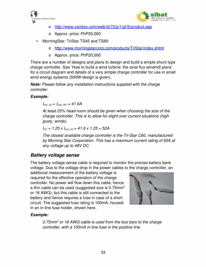
Battery voltage senseThe battery voltage sense cable is required to monitor the precise battery bank voltage. Due to the voltage drop in the power cables to the charge controller, an additional measurement of the battery voltage is required for the effective operation of the charge controller. No power will flow down this cable, hence a thin cable can be used (suggested size is 0.75mm2
or 18 AWG), but this cable is still connected to the battery and hence requires a fuse in case of a short circuit. The suggested fuse rating is 100mA, housed in an inline fuse holder, shown here.
Example:
0.75mm2 or 18 AWG cable is used from the bus bars to the charge controller, with a 100mA inline fuse in the positive line.
33

Charge controller cable sizingAgain, the ‘cable sizing’ design procedure is followed here to size the power cable from the bus bars in the power house to the charge controller and on to the dump load.
The current used to size this cable should be the maximum current from the wind turbine, Imax_WT = Pmax_WT / Vsys, with a safety factor of 25% added, ICC_cbl_min = 1.25 x Imax_WT. An acceptable voltage drop is 5%.
Example:
Maximum wind turbine current, IWT_max = PWT/Vsys = 1000/24 = 41.6A
Current rating for cable ICC_cbl_min = IWT_max x 1.25 = 52A
Distance from bus bars to dump load via the charge controller , L = 5m.
Allowable voltage drop, Vd_% = 5%.
Cross sectional area of wind turbine cable required:
Amin_batt = (2 x IWT_cbl_min x xρ L) / ( (Vsys x Vd_%) / 100) = 7.3mm2
Using standard values: Abatt = 8mm2 or 8 AWG
BreakerAs mentioned in the ‘cable sizing’ section, the rating of the breaker must be 1.25 times the cable current (ICC_cbl_min). This will allow for a safety margin to ensure no nuisance tripping. Ifuse = 1.25 x Icable.
Choose the next standard breaker size above the calculated breaker rating.
A twopole breaker is used (braking both positive and negative lines) so that the AC rating of the breaker can be the DC current rating required.
Example:
Imin_CC = 41.6A
ICC_cbl_min = 1.25 x Imin_CC = 52A
ICC_fuse_min = 1.25 x ICC_cbl_min = 65A
The closest standard available breaker size above this value is 100A. Hence the breaker rating (ICC_fuse) is 100A
Dump loadThe dump load is just a resistive load which will dissipate any excess power as heat. This is rated to be able to dissipate the full power from the wind turbine.
The two important design parameters are the resistance and the power dissipation.
34

The power dissipation is just the rated power of the wind turbine, PWT.
The resistance of the dump load can be calculated from:
Power = V x I, V= I x R, hence Power = V2 / R,
Rearranged this to give: Rdump = Vsys2 / PWT.
Usually the resistance will be relatively low and the full load must be comprised of a number of resistive elements in parallel. Ensure that all the power ratings of the resistive elements are correctly calculated.
The dump load will get hot in use: ensure the unit is protected but has very good air flow through the elements to effectively dissipate the heat.
The cable size to the dump load will be the same at that calculated for the charge controller.
Example:
PWT = 1000W, hence Pdump = 1000W
Vsys = 24V, therefore Rdump = Vsys2/PWT = 242/1000 = 0.576Ω
Cable sizing comes from the ‘charge controller cable sizing’ section.
Using standard values: Abatt = 8mm2 or 8 AWG.
Charge controller monitoringThis device is optional. It would be useful to monitor the energy flows and the amount of energy dumped by the charge controller and for fault diagnosis, but it would be uneconomic to install on every system.
As mentioned in the ‘battery monitoring’ section, an amphour meter monitors the current flowing in a cable and hence calculates the amphours. This can be used to monitor the amphours dumped by the charge controller, which gives an indication of the energy dumped.
Please see the ‘battery monitoring’ section for suppliers of amphour meters.
A modification of an amphour meter is the watthour meter. This measures the current and the voltage and hence calculates the power to the charge controller. It measures this over time which gives the total energy dumped.
Unfortunately, no lowcost, off the shelf watthour units for low voltage DC are easily available. If this was to be installed then a bespoke unit would have to be produced.
35

DC loadsDepending upon the system design, some of the loads will be powered directly from the battery bank at the DC system voltage. These loads could include lights and radios. These loads should be listed and assessed within the ‘load resource assessment’.
The DC load supply system is relatively simple, comprising:
Wh Output to various24V DC loads
Cable sizeAgain, the ‘cable sizing’ design procedure is followed here to size the power cable from the bus bars in the power house to the DC loads.
The current used to size this cable should be the maximum current demand of the DC loads, IDC_max = Pload_DC_max / Vsys, with a safety factor of 25% added, IDC_cbl_min = 1.25 x IDC_max. An acceptable voltage drop is 5%.
Example:
Maximum DC load current, IDC_max = Pload_DC_max/Vsys = 380/24 = 8.3A
Current rating for cable IDC_cbl_min = IDC_max x 1.25 = 10.4A
Distance from bus bars to dump load via the charge controller , L = 10m.
Allowable voltage drop, Vd_% = 5%.
Cross sectional area of wind turbine cable required:
ADC_min = (2 x IDC_cbl_min x xρ L) / ( (Vsys x Vd_%) / 100) = 2.9mm2
Using standard values: ADC = 3.5mm2 or 12 AWG
BreakerAs mentioned in the ‘cable sizing’ section, the rating of the breaker must be 1.25 times the cable current (IDC_cbl_min), i.e. Ifuse = 1.25 x Icable. This will allow for a safety margin to ensure no nuisance tripping. Choose the next standard breaker size above the calculated breaker rating.
A twopole breaker is used (braking both positive and negative lines) so that the AC rating of the breaker can be the DC current rating required.
Example:
36

IDC_max = 8.3A
IDC_cbl_min = 1.25 x IDC_max = 10.4A
IDC_fuse_min = 1.25 x IDC_cbl_min = 13.0A
The closest standard available breaker size above this value is 20A. Hence the breaker rating (IDC_fuse) is 20A
DC load branchesThe above cable size and breaker rating is calculated for the full maximum DC load. Often, the maximum DC load is comprised of a number of smaller DC loads. It is advisable to break the loads into small ‘branches’ which can use smaller cables along with lower fuse ratings. The lower fuse ratings will also help with protection of the various DC loads. For example, if the DC loads were just protected by a 30A breaker and a 20W (<1A at 24V) fluorescent light developed a fault then more than 30A would have to flow before the breaker cuts the supply. This current could easily cause more damage to components and wiring within the 20W light before the fuse trips. If the light was on a separate branch, protected by a 2A fuse, then only 2A would flow before the fuse trips, which would be unlikely to cause additional problems.
Using branching also means that smaller (and hence less expensive) cables can be run to individual loads.
An additional benefit comes from breaking up the load into smaller branches. If only one breaker is used then, if one device trips, all the loads will be cut off. If numerous smaller branches are used then only the loads on that branch will trip out, while still supplying all the other loads on the other branches.
Note: There must always be discrimination in the circuit. This means that fuse sizes from the supply (battery) to the load must stay the same or get smaller, they should never increase in rating.
37

DC load monitoring
Ammeter
Again, it is very useful to monitor the current to the DC loads. An ammeter with a minimum rating of IDC_max should be installed in the line to the battery. Please see the ‘Ammeter’ section of the ‘Wind turbine’ chapter for more details. Technically, the ammeter is optional but it is simple and cheap to install and very useful when monitoring and performing fault diagnostics on the system, hence it should be installed on every system.
Amphour or watthour meter
It would also be useful to monitor the energy flows and the amount of energy consumed by the DC loads, but increases the system cost. This is an optional device. Monitoring the DC (along with the AC) loads and the energy from the wind turbine would also help the system operator. The operator could easily see how much energy had been generated and consumed and hence tell the performance of the system.
As mentioned in the ‘battery monitoring’ section, an amphour meter monitors the current flowing in a cable and hence calculates the amphours. This can be used to monitor the amphours consumed by the DC loads, which gives an indication of the energy consumed.
Please see the ‘battery monitoring’ section for suppliers of amphour meters.
A modification of an amphour meter is the watthour meter. This measures the current and the voltage and hence calculates the power to the DC loads. It measures this over time which gives the total energy consumed.
Unfortunately, no lowcost, off the shelf watthour units for low voltage DC are easily available. If this was to be installed then a bespoke unit would have to be produced.
38
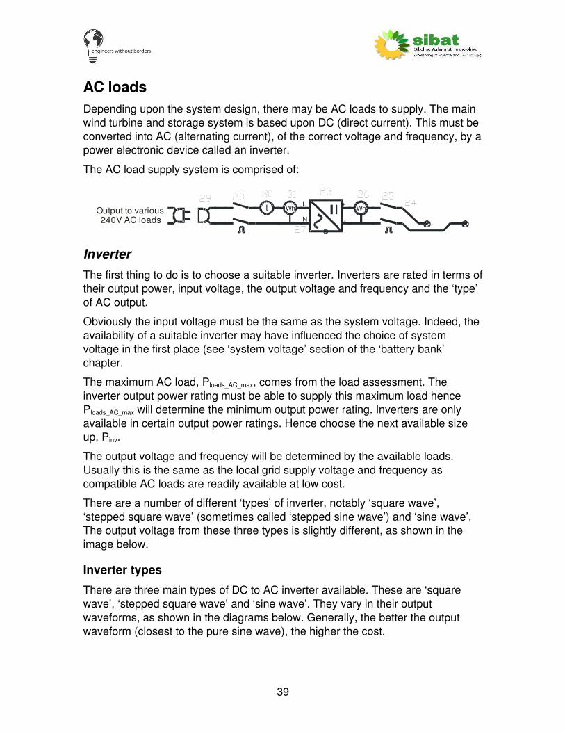
AC loadsDepending upon the system design, there may be AC loads to supply. The main wind turbine and storage system is based upon DC (direct current). This must be converted into AC (alternating current), of the correct voltage and frequency, by a power electronic device called an inverter.
The AC load supply system is comprised of:
L
N+
Wht WhOutput to various240V AC loads
InverterThe first thing to do is to choose a suitable inverter. Inverters are rated in terms of their output power, input voltage, the output voltage and frequency and the ‘type’ of AC output.
Obviously the input voltage must be the same as the system voltage. Indeed, the availability of a suitable inverter may have influenced the choice of system voltage in the first place (see ‘system voltage’ section of the ‘battery bank’ chapter.
The maximum AC load, Ploads_AC_max, comes from the load assessment. The inverter output power rating must be able to supply this maximum load hence Ploads_AC_max will determine the minimum output power rating. Inverters are only available in certain output power ratings. Hence choose the next available size up, Pinv.
The output voltage and frequency will be determined by the available loads. Usually this is the same as the local grid supply voltage and frequency as compatible AC loads are readily available at low cost.
There are a number of different ‘types’ of inverter, notably ‘square wave’, ‘stepped square wave’ (sometimes called ‘stepped sine wave’) and ‘sine wave’. The output voltage from these three types is slightly different, as shown in the image below.
Inverter types
There are three main types of DC to AC inverter available. These are ‘square wave’, ‘stepped square wave’ and ‘sine wave’. They vary in their output waveforms, as shown in the diagrams below. Generally, the better the output waveform (closest to the pure sine wave), the higher the cost.
39

Voltage
Time
VoltageVoltage
Time
Time
Square Wave
Stepped Square Wave (or Modified ‘Sine’ Wave)
Sine Wave
Pure sine wavefor reference
‘Square wave’
Simplest and hence cheapest Sometimes the attached loads do not work
High power ratings available at lowest cost
Sometimes problems with overheating in loads (e.g. motor coils)
Sometimes problems with high pitched noise from the device
Cannot use AC meters to exactly measure the current
Typically low efficiency
‘Stepped square wave’
Reduced heating in loads Sometimes the attached loads do not work
High power ratings available at low cost
Sometimes problems with high pitched noise from the device
Relatively good efficiency Cannot use AC meters to exactly measure the current
‘Sine wave’
40

Can supply ALL types of loads Most expensive
High efficiency
Can use ‘off the shelf’ AC meters
If possible use a sinewave inverter as this will be able to supply all types of loads. If the load is relatively simple (such as a single pump) a stepped squarewave inverter can be used. If at all possible, do not use a square wave inverter.
Note: Some suppliers do not directly specify the inverter type and some use jargon to try and hide the inverter type (usually when it is a cheaper inverter being sold as a more expensive ‘sine wave’ type). Read the specifications and literature carefully.
Manufacturers of good quality DC to AC power inverters include:
Xantrex (Trace) http://www.xantrex.com/
Exeltech http://www.exeltech.com/
SMA http://www.sma.de/
Outback Power Systems http://www.outbackpower.com/
Fronius http://www.fronius.com/cps/rde/xchg/
Suppliers of inverters in the Philippines include:
Solarco http://www.solarelectric.com.ph/about.php
MATECH – No website [email protected]
Physics Research http://www.geocities.com/prsearch2000/
Note: This list is in no way exhaustive. Inclusion on this list in no way represents any approval of services or products.
The inverter will require a ground connection, see ‘system grounding’ section of ‘practical considerations’ chapter for more details.
Example:
In this example the minimum inverter power, Pinv_min, is 400W.
The next available sized inverter (for example) is 600W. Hence Pinv = 600W.
This is a sine wave output inverter, with an output voltage of 240V AC at 60Hz, as required by the loads.
41
DC cable sizeThe inverter is usually located relatively close to the battery bank. The cable from the battery to the inverter can carry very high currents so it is important to ensure this cable is designed correctly. If possible use even thicker cable than the calculation suggests. The standard ‘cable sizing’ design procedure is followed again.
The current used to size this cable should be the maximum current to the inverter, IinvDC_max = Pinv / Vsys, with a safety factor of 25% added, IinvDC_cbl_min = 1.25 x IinvDC_max. The voltage drop on this cable can affect the operation of the inverter hence it is best to design for a low voltage drop. An acceptable voltage drop is just 2%. As this cable is relatively short, it will not incur high additional cost.
Example:
Maximum inverter DC current, IinvDC_max = Pinv / Vsys = 600/24 = 25A
Current rating for cable IinvDC_cbl_min = IinvDC_max x 1.25 = 31.2A
Distance from bus bars to the inverter , L = 3m.
Allowable voltage drop, Vd_% = 2%.
Cross sectional area of wind turbine cable required:
Amin_batt = (2 x IinvDC_cbl_min x xρ L) / ( (Vsys x Vd_%) / 100) = 6.5mm2
Using standard values: Abatt = 8mm2 or 8 AWG
DC side breakerAs mentioned in the ‘cable sizing’ section, the rating of the breaker must be 1.25 times the cable current (ICC_cbl_min). This will allow for a safety margin to ensure no nuisance tripping. Ifuse = 1.25 x Icable.
Choose the next standard breaker size above the calculated breaker rating.
A twopole breaker is used (braking both positive and negative lines) so that the AC rating of the breaker can be the DC current rating required.
Example:
IinvDC_max = 25A
IinvDC_cbl_min = 1.25 x IinvDC_max = 31.2A
IinvDC_fuse_min = 1.25 x IinvDC_cbl_min = 39A
The closest standard available breaker size above this value is 60A. Hence the breaker rating (IinvDC_fuse) is 60A
42
AC cable sizeAgain, the ‘cable sizing’ design procedure is followed here to size the AC cable from the inverter to the AC loads.
The current used to size this cable should be the maximum current from the wind turbine, Imax_WT = Pmax_WT / Vsys, with a safety factor of 25% added, ICC_cbl_min = 1.25 x Imax_WT. Due to the high voltage (and hence lower currents) this cable will be much smaller than the other power cables in the system. An acceptable voltage drop is 5%.
Example:
Maximum inverter AC current, IinvAC_max = Pinv / Vinv = 600/240 = 2.5A
Current rating for cable IinvAC_cbl_min = IinvDAC_max x 1.25 = 3.1A
Distance from bus bars to the inverter , L = 20m.
Allowable voltage drop, Vd_% = 5%.
Cross sectional area of wind turbine cable required:
Amin_batt = (2 x IinvDC_cbl_min x xρ L) / ( (Vsys x Vd_%) / 100) = 1.7mm2
Using standard values: Abatt = 2mm2 or 14 AWG
AC side breakerAs mentioned in the ‘cable sizing’ section, the rating of the breaker must be 1.25 times the cable current (ICC_cbl_min). This will allow for a safety margin to ensure no nuisance tripping. Ifuse = 1.25 x Icable.
Choose the next standard breaker size above the calculated breaker rating.
As this is an AC rated unit, breakers are readily available at the correct voltage ratings. The breaker is only required in the Live (or ‘Hot’) line, although a two pole breaker used in both Live and Neutral would be even better (it would allow full isolation of the AC system) and would not incur a large cost penalty.
Example:
IinvAC_max = 2.5A
IinvAC_cbl_min = 1.25 x IinvAC_max = 3.1A
IinvAC_fuse_min = 1.25 x IinvAC_cbl_min = 3.9A
The closest standard available breaker size above this value is 5A. Hence the breaker rating (IinvAC_fuse) is 5A
43
AC load monitoring
Current on AC side
Again, it is very useful to monitor the current to the AC loads. An ammeter with a minimum rating of IAC_max should be installed in the line to the battery. Due to the prevalence of AC systems, AC ammeters are very easy to find in most electrical supply shops and relatively cheap. Technically, the ammeter is optional but it is simple and cheap to install and very useful when monitoring and performing fault diagnostics on the system, hence it should be installed on every system.
Wh or Ah monitoring on DC side
This device is optional. It would be useful to monitor the energy flows and the amount of energy consumed on the DC input to the inverter, but this increases the system cost. If both the DC input and the AC output from the inverter are measured then the long term efficiency of the inverter can be measured, which might help with future system design.
As mentioned in the ‘battery monitoring’ section, an amphour meter monitors the current flowing in a cable and hence calculates the amphours. This can be used to monitor the amphours consumed by the inverter, which gives an indication of the energy consumed.
Please see the ‘battery monitoring’ section for suppliers of amphour meters.
A modification of an amphour meter is the watthour meter. This measures the current and the voltage and hence calculates the power to the inverter. It measures this over time which gives the total energy consumed.
Unfortunately, no lowcost, off the shelf watthour units for low voltage DC are easily available. If this was to be installed then a bespoke unit would have to be produced.
Wh or Ah monitoring on AC side
This device is optional. Monitoring the Watthours or Amphours on the AC output of the inverter would help record the energy consumed by the loads. As mentioned in the ‘DC load monitoring’ section, monitoring the AC (along with the DC) loads and the energy from the wind turbine would also help the system operator.
Due to the prevalence of AC devices, watthour and amphour meters for AC systems are relatively easy to obtain. These show cumulative total energy consumed by the AC loads. Both mechanical and electronic meters are available.
44

A typical mechanical AC watthour meter.
Time run meter
If required, a meter can be added on the AC output of the inverter to measure the time that an AC output has been available. This could be useful to see how long a pump has run, for example, or to look at the length of time power has been available to look at the system reliability. Also, it can be used, along with a Wh meter to find the average output load when the AC output is available.
This item is definitely optional and should only be installed if there is a good reason to.
45

Other equipment
System voltage monitor
A meter to measure the system voltage is vitally important. This meter is used by the system operator to assess the state of charge of the battery (although this does require some skill and experience).
The system voltage monitor is comprised of:
V
This voltmeter must accurately display the system voltage within a useful range. If a 050V voltmeter is used then it is very difficult to view the small changes in system voltage. The displayed range of voltages will depend upon the system voltage, but as a general rule will be from 0.85 x Vsys to 1.4 x Vsys. For example:
System voltage Minimum voltage Maximum voltage
12 10 16
24 20 30
48 40 60
The system voltage can be used, along with the graph below to give an indication of the state of charge of the battery. The system operator uses this information in order to make decisions on running the various loads on the system.
This graph is a generic ‘map’ of the state of charge of a typical battery depending upon the system voltage and the current into or out of the battery. The various lines relate to different current rates. The current can be calculated knowing that C is the total installed battery bank capacity in amphours.
Example:
Cbatt = 1000Ah, there are 50A flowing into the battery (charging) and the system voltage reads 13.5V.
Cbatt / 50A = 20, therefore look at the C/20 line.
Where this hits the 13.5V relates to approx. 85% SOC.
This graph was taken from this very good article on battery SOC measurement: http://www.arttec.net/Solar_Mower/4_Electrical/Battery%20Charging.pdf
It was first published in Home Power Magazine #36, Aug/Sept 1993 entitled ‘LeadAcid Battery State of Charge vs Voltage’, By Richard Perez.
46

47
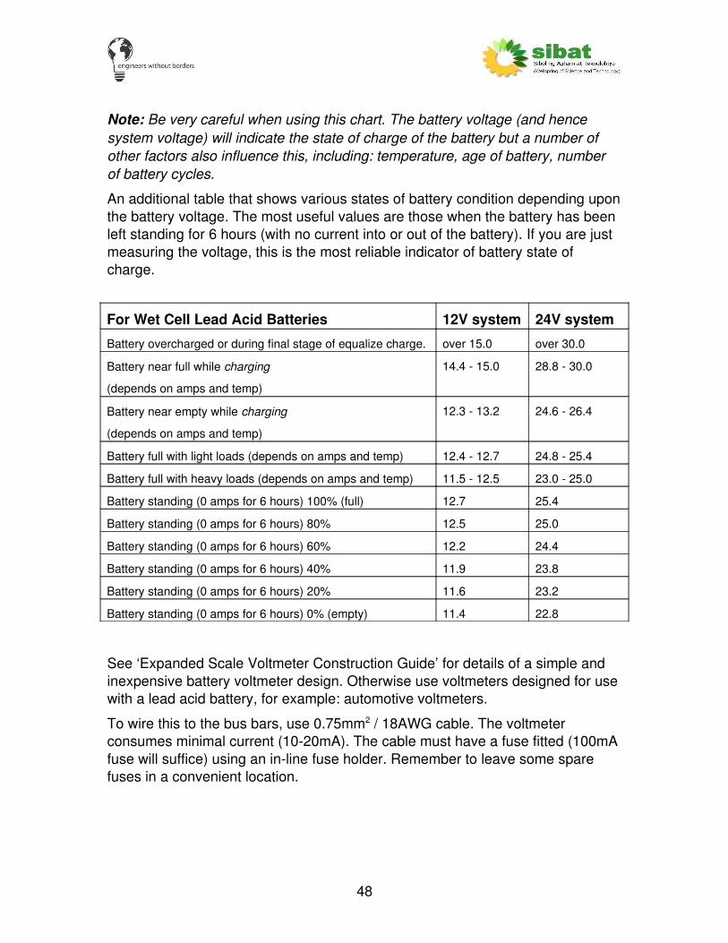
Note: Be very careful when using this chart. The battery voltage (and hence system voltage) will indicate the state of charge of the battery but a number of other factors also influence this, including: temperature, age of battery, number of battery cycles.
An additional table that shows various states of battery condition depending upon the battery voltage. The most useful values are those when the battery has been left standing for 6 hours (with no current into or out of the battery). If you are just measuring the voltage, this is the most reliable indicator of battery state of charge.
For Wet Cell Lead Acid Batteries 12V system 24V system
Battery overcharged or during final stage of equalize charge. over 15.0 over 30.0
Battery near full while charging
(depends on amps and temp)
14.4 15.0 28.8 30.0
Battery near empty while charging
(depends on amps and temp)
12.3 13.2 24.6 26.4
Battery full with light loads (depends on amps and temp) 12.4 12.7 24.8 25.4
Battery full with heavy loads (depends on amps and temp) 11.5 12.5 23.0 25.0
Battery standing (0 amps for 6 hours) 100% (full) 12.7 25.4
Battery standing (0 amps for 6 hours) 80% 12.5 25.0
Battery standing (0 amps for 6 hours) 60% 12.2 24.4
Battery standing (0 amps for 6 hours) 40% 11.9 23.8
Battery standing (0 amps for 6 hours) 20% 11.6 23.2
Battery standing (0 amps for 6 hours) 0% (empty) 11.4 22.8
See ‘Expanded Scale Voltmeter Construction Guide’ for details of a simple and inexpensive battery voltmeter design. Otherwise use voltmeters designed for use with a lead acid battery, for example: automotive voltmeters.
To wire this to the bus bars, use 0.75mm2 / 18AWG cable. The voltmeter consumes minimal current (1020mA). The cable must have a fuse fitted (100mA fuse will suffice) using an inline fuse holder. Remember to leave some spare fuses in a convenient location.
48

Power house lightingA light within the power house is optional but nearly always installed. This will be powered directly from the battery bank. A standard design is used. If additional lights are required then this design can just be repeated.
The powerhouse lighting is comprised of:
Fluorescent
Fluorescent lights designed for use at the system voltage are used. For 12V and 24V systems these are readily available. Typically a 20W unit is enough to light a small power house.
Use 0.75mm2 / 18AWG cable. The cable must have a fuse fitted (usually 2A, although this can be calculated from the system voltage and light power rating, remembering to include an additional 25% fuse factor). Again, use an inline fuse holder.
49

Design spreadsheetIn order to simplify all these calculation, an excel spreadsheet has been produced to perform a full design for all the cables, fuses, power ratings and battery bank sizes. This guide was written to explain all the choices and calculations made. Some ratings must be checked by the system designer as each electrical system is different.
There are 7 worksheets, but in practice only the first two (with names in capitals) are really used. The worksheets are listed here with detail on the information they contain.
MAIN DESIGN
This is the main page where all the external data required is entered and the output data is given. Wherever there is a value with a white background: that is a data INPUT. All the data inputs should be explained in this guide.
The output data is shown next to the relevant parameter description. There are a number of highlighted sections (usually bright red or bright green) which show if the decision made by the system designer will allow a suitable design. If the section is red then the design choice is not correct. If green then the choice is suitable.
The outputs from this spreadsheet should be carefully considered. It is easy to enter numbers into a spreadsheet without fully thinking about the outputs. Check all the component sizings. Do they seem within the right ball park?
SYSTEM DIAGRAM
50
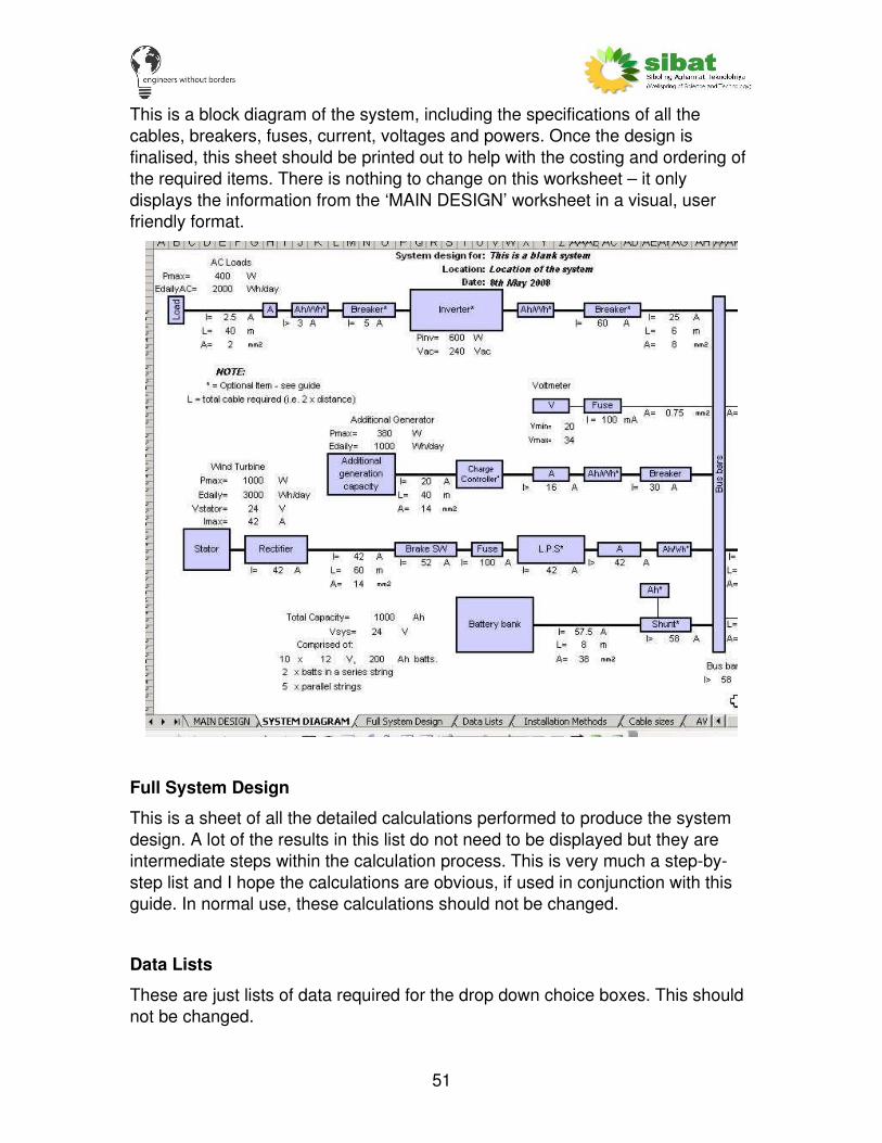
This is a block diagram of the system, including the specifications of all the cables, breakers, fuses, current, voltages and powers. Once the design is finalised, this sheet should be printed out to help with the costing and ordering of the required items. There is nothing to change on this worksheet – it only displays the information from the ‘MAIN DESIGN’ worksheet in a visual, user friendly format.
Full System Design
This is a sheet of all the detailed calculations performed to produce the system design. A lot of the results in this list do not need to be displayed but they are intermediate steps within the calculation process. This is very much a stepbystep list and I hope the calculations are obvious, if used in conjunction with this guide. In normal use, these calculations should not be changed.
Data Lists
These are just lists of data required for the drop down choice boxes. This should not be changed.
51
Installation Methods
This is a list of the various cable installation methods, along with their derating factors. Additional cable installation methods and cable derating factors can be added to this list, although this should not be necessary.
Cable sizes
This is a list of the standard metric cable sizes. This data has been taken from the Philippine Electric Code 2000. Additional cables can be added but only if they are then relisted in ascending order.
AWG metric conversion
This is a list of the AWG sizes along with the metric equivalent. This should not need to be changed.
52
Practical issuesApart from the technical design shown here, in order for an electrical system to work effectively, it must be well constructed with general good practice used during every stage of installation. Small wind turbine based renewable energy systems are usually installed in remote areas and hence long term reliability is a very important requirement. It is not easy to obtain spare parts and the delay in obtaining and transporting spare parts can easily put the system out of action for a long time. A well constructed system should be reliable for the whole lifetime of the project (a minimum of 15 years). Any short cuts made during the installation can reduce the system reliability and could affect the project’s lifetime.
Effort should be spend ensuring the system is well constructed but, as with life, no system is without its problems. The aim of this guide is to show the basic system design and raise issues that must be considered before the project is installed. This should minimise, as far as possible, any potential problems
System layoutAn important aspect of system installation is a good system layout. This requires skill and experience from the system designer. General points to consider include:
• Ensure battery bank and power house is well ventilated.
• Ensure no electrical devices are placed directly above the battery bank.
• Ensure very thick cable used to join individual batteries within the battery bank.
• Take the positive and negative cables from different ends of the battery bank. This should ensure more even discharging of the batteries.
• Ensure high current cable runs are kept as short as possible.
• Ensure all cables and system components are accessible and removable in case of testing or repair.
• Ensure the layout of the meters and breakers is thought through to make them easy to read, but without excessive cable run deviations.
• Try to ‘insectproof’ the various system components. Use screens or sealant. Use insect repellent every month if infestations occur.
• The use of bus bars as a power distribution system makes it easy to connect the various generators and loads.
• Ensure all cable connections are well constructed. Remember this should be designed for a lifetime of 15 to 20 years.
53

• Build and test as much of the system as possible before going to the site.
It might be best to build and test as much as possible of the system (such as the bus bars, system voltmeter and ammeters) in a workshop. This can then be transported to the site and installed relatively quickly and easily.
A system layout plan should be made using the correct sizes of equipment to help the installation when on site.
System groundingWind turbine grounding has already been covered in the ‘Wind turbine’ section. The wind turbine grounding is only to provide a path to ground for lightning – it is not the same as a ground required for AC systems.
If the system includes a higher voltage (e.g. 110 or 240V) AC section then a system ground is required. This provides a path for current in the event of a fault and ensures that any fuses within the system function correctly. Only one system ground is required from which all ground connections should be made.
A number of techniques can be used to create a system ground including:
• Copper grounding rod hammered into the ground
54

• Metal rebar of building foundations used to form ground
• Large metal object with high surface area (e.g. car radiator) buried into the ground
But with any of these techniques an earth resistance test must be made using a special earth resistance tester (used by all electricians). This applies a voltage and measures the resistance to ensure that, if there is a fault to ground, the resistance is low enough for a current to flow and hence operate any fuses or breakers.
The local electrical code must be followed with the installation of any system grounding. For this section it is usually best to ask a local electrician.
A thick (10mm2, 6AWG – again, check the local electrical code) earth cable must be connected to the system ground and taken to a point where all the ground connections can be made. Measures should be taken to ensure that this connection is well made and that there is no corrosion.
Cable connectionsNumerous electrical connections will be made within the renewable energy system. It is important to ensure that all these connections are well made, with very low resistance, high mechanical strength and resistance to corrosion.
Weak and badly made electrical connections can seriously affect system performance. Due to the low voltages and hence relatively high currents, any small resistance will introduce some power loss (remember P = I2 x R). In addition, bad connections can become corroded or loose and this will affect system reliability. It also may mean that temporary repairs are made, which could cause other problems. A renewable energy system should be designed for a 15 to 20 year lifespan – this includes all electrical connections.
There are numerous ways of making electrical connections between two cables. The choice of connector will depend upon locally available parts and skills. A few typical types of connector are shown here. Plugs and sockets for high currents are usually very expensive and not standard, hence are not typically used.
Twisted wire
This is the most basic way of connecting two or more cables. No additional connectors are required, only some tape, hence this type of connection is normally used as it is the cheapest and easiest.
If not constructed well, problems include corrosion of wires, loose connections, short circuits and high resistance. Numerous problems with system operation have come about due to badly made twisted wire connections. Also if the cable or equipment must be removed then this connection must usually be cut out. This
55

results in a slightly shorter cable, which can lead to problems if it must be done a number of times. For these reasons I suggest that, if possible, another method of wire connection is used.
If this system is used (sometimes it is the only connection method available), then ensure that the cables are well twisted together and that self amalgamating rubber tape is used. It is usually best if both cables are of similar thickness. This will give a reasonably strong and reasonably damp proof connection.
56

Connector block
The next most popular connection method is the use of a connector block (sometimes called ‘Choc’ block). The connector block comprises a number of metal connecting tubes set into plastic. Wires can enter the metal tubes from each side and a metal screw is tightened to hold the wire in place. They are designed mainly for higher voltage AC connections, but high current versions can be found. Typically the whole block is the encased in tape, although, if enclosed, this should not be necessary due to the plastic.
This is a simple, cheap and easily available method for cable connection, which also allows relatively easy disconnection. Some problems do occur including
57

loose connections (a very common problem), broken wires (the wire sometimes bends near the entry point and can break at that point) and problems with corrosion. Also, if more than two wires are to be connected, then the smaller diameter cable can sometimes fall out as the screw will only hold the larger cable.
The stop any potential problems, ensure that the screws are tightened very well and that it ‘bites’ well onto the cable, ensure the connector block is not ‘wiggled’ too much and that the block is coated with electrical or rubber self amalgamating tape.
58

Examples of connector blocks. Many different types are available. Ensure that the connector is rated for the maxcurrent flowing and is the correct size for the cable used.
Place both wires into the connector.Ensure they are both well pushed intothe connector. Tighten very well.
Connection is complete.
Use a knife to cut throughthe cable insulation in a neat circle. The insulationcan then be removed.
Although the plastic outer is designed to insulate the terminal it is awise precaution to wrap the whole connection in selfamalgamatingrubber or electrical.
Remove only enough insulationfor the copper to fit into half of the
connector.
Bolted ring connectors
This technique is not standard practice but is one of the best I have seen to produce a reliable connection which can easily be disconnected. It is also a relatively cheap method which does not require too many additional parts.
The technique involves putting a good quality ring connector onto the end of both cables. These ring connectors can then be bolted together with a standard nut and bolt, along with a spring washer.
59

Advantages are that numerous cables can easily be connected together, the cables can relatively easily be disconnected and a good electrical connection is made. Good quality ring connectors with a thick metal ring must be used. The cable must be well crimped into the connector (and soldered if the facilities are available).
The whole connection must be covered in rubber, self amalgamating tape to provide a layer of electrical insulation and some waterproofing. One problem is
60

that this tape must be cut off if the cable must be disconnected, although the same problem occurs with most connection methods.
Water proof connections
There are a number of ways to make a fully water proof connection. Shown here is one way to create a fully waterproof connection for minimal cost. The major disadvantage of this system is that it is permanent. The connection must be physically cut off to access the cables again. Ensure that, if this connection is used, there is a point at which the cable can be accessed (perhaps where the cable terminates).
61

62

Long distribution cablesSometimes the wind turbines must be sited a relatively long distances (over 100m) from the load they must supply (e.g. the community).
If possible site the wind turbine as close as possible to the load. This will minimise the cost of the project both in terms of cost of the cables and losses.
If it is not possible then there are a number of techniques that could be used to transmit the power. The various options and their features are discussed here.
63

1. Low voltage DC cable
The most obvious technique would be to run a long, low voltage (i.e. 12 to 48V DC) cable. The powerhouse would be located close to the load.
The advantages of this include: Simple Requires no additional complex equipment
64

Powerhouse close to load which is usually close to the community
Disadvantages include: Either very high losses within cables
o This is due to the high currents and the resistive losses Or very expensive, thick cables required
2. High voltage DC cable
The voltage generated by the stator could be much higher. This could be adjusted by increasing the number of turns in the coils within the stator. The powerhouse is located near the load. Depending upon the voltage of the storage system (if lead acid batteries are used) some form of DC to DC converter might be required.
The advantages of this include: Higher voltage, hence thinner cheaper wires can be used Adjusting stator voltage has virtually zero cost
Disadvantages include: Any voltage above 55V DC is dangerous. Additional safety measures
would have to be in place Must ensure the rectifier is suitable for the voltage An additional DC/DC converter may be required which may be expensive
Warning: Do not use a high voltage battery bank. For these systems, use a battery bank voltage of 48V or less.
3. Low voltage AC cable
Another technique could be to send the AC output of the stator from the wind turbine to the powerhouse, located close to the load. The rectifier would then be housed within the powerhouse.
There are no advantages to this compared to low voltage DC.
Disadvantages include: Similar power losses to low voltage DC Three expensive, thick cables are required
4. High voltage AC cable, powerhouse near load
The power house is placed close to the load. The AC generated by the stator is stepped up to a higher AC voltage through a transformer. Another transformer steps down the voltage within the powerhouse.
The advantages of this include: High voltage, hence lower cable losses Less expensive, thin cables can be used
65

Disadvantages include: Requires a number of additional transformers Transformers must deal with the variable frequency, variable voltage
output of the wind turbine. They may need to be specially designed.
5. High voltage AC cable, powerhouse near wind turbine
The powerhouse is place near the wind turbine. The DC cables from the wind turbine are kept short. An inverter is used within the powerhouse. The cable from the powerhouse to the loads would be at the standard output from the inverter (typically 240V 60Hz AC within the Philippines).
The advantages of this include: Higher voltage AC, hence thinner, less expensive cables Standard voltages, hence standard equipment can be used.
Disadvantages include: An inverter is required
o Although may systems would require an inverter already Powerhouse could be far from the community which could make it difficult
for the operator. If the distance is very far then, perhaps, additional transformers are
required to step up and step down the voltage.
Recommendations
From the various configurations presented just two are recommended.
If the distance from the wind turbine site has to be relatively far then the recommendation is to use the ‘High voltage AC cable, powerhouse near wind turbine’. This is the best mixture of lowest cost and most standard equipment.
If the system does not use a battery bank then it is suggested that a higher voltage DC system could be used, but be careful with the design of the system in this case, both in terms of safety and ensuring the wind turbine is correctly controlled.
GeneratorsSometimes a diesel generator is added to the system. This provides the system with a reliable and controllable source of energy. Obviously some cost is involved both in cost of diesel fuel and environmental damage.
Both the electrical integration and the control strategy must be carefully thought through to ensure a reliable and robust system.
Every electrical system is different but some ideas and thoughts on the main concepts are included here.
66

Note: These are just ideas and none have been implemented by the author.
Note: Please review the Practical Action information on Diesel and generators for more details: http://practicalaction.org/practicalanswers/product_info.php?cPath=21_64&products_id=34
Electrical integration
Obviously the generator must be electrically connected to the system. Generators usually supply an AC output voltage (240V 60Hz in the Philippines). Some generators are specifically designed to recharge a battery bank and they have a built in battery charger.
L
N
+
t Wh
DC breakerBattery ChargerAC breaker
* Run t
ime
* Wh m
eter
* = Optional
BatteryBank
Generator
The electrical connections required to integrate a generator into the system.
Correct electrical installation must be followed when integrating the generator into the system. Correct cable sizing procedures should be followed. The cable from the generator should be protected from vibration (flexible cable used) and heat (some additional cable insulation or guard is required). Breakers are required on both the AC and the DC cables to protect the relevant cable. Additionally a run time monitor and a Wh energy meter could be added. This information could be used to review how long the generator is running for and hence adjust any control strategy. The run time could also be used to indicate when essential maintenance should be performed.
Sizing generatorsGenerators are rated in terms of the VA (voltamps) they can supply. This is the apparent power that the generator can supply, as opposed to the real power, measured in watts (W). Due to power factor (which shows that not all of the apparent power does useful ‘real’ work), it is the apparent power which is the most important value when sizing a generator.
The generator must be sized correctly to recharge the battery bank.
The general rule is that a battery should be charged at a current equal to 1/10th to 1/8th of the battery bank Ah capacity. For example: If the battery capacity is 1000Ah, then the ideal recharge current for the battery is between 1000/8 = 125A and 1000/10 = 100A. This must be supplied at the correct system voltage. If the
67

battery bank is at 24V then the power supplied to the battery must be 125A x 24V = 3000W.
If used, the power factor of the battery charger must also be taken into account. This would be in the region of 0.8, hence the generator VA rating must be able to supply the real power at the stated power factor. Therefore a generator sized around 3000 / 0.8 = 3750VA (3.75kVA) is required.
Obviously a larger or smaller generator could be used but this would lead to some problems. A generator which is too small might not be able to keep the battery charged when it is required. A generator that is too large would not be efficient as it would be running at a low load for the majority of the time and would consume more diesel than a correctly sized unit. This is due to the low efficiency of a generator at low loading levels, as shown in the following graph.
Control strategies
The control of the generator (i.e. when to turn it on and off) is one of the main problems with integrating a generator. If the control strategy is incorrect then it could mean an inefficient system with lots of diesel consumed. A good control strategy would ensure full use of the available renewable energy and keep diesel consumption to a minimum while still ensuring the loads are supplied and the batteries are kept in good condition.
The optimal control strategy would be to only switch on the generator when the battery is empty and there will be no renewable energy input for a length of time. This requires knowledge of the future conditions (knowing if there will be any renewable energy input). Obviously this is very difficult to do as the renewable
68

energy input is variable, even with weather forecasting. It is almost impossible to do with a simple control system.
A simple, robust control strategy is required.
Operator controlThis is based upon human input. The system operator is in full control of the generator. It is their judgment on when to run the generator. This requires a very well trained and reliable system operator.
The advantages of this include: Very adaptable Can make judgements on future system use Ensures the system is fully checked before running the generator Can respond to any problems
Disadvantages include: Requires training Requires an operator to regularly check the system
Automatic controlAn automatic control system removes the need to have a system operator. Based upon various system information (typically voltage and currents flowing) some form of electronic control will start or stop the generator to ensure the loads are supplied and the battery is kept in optimum condition.
There are many ways this can be implemented including various levels of intelligence.
The best strategy is a compromise between intelligence (with associated complexity) and reliability (simpler systems tend to be more robust and hence reliable).
Automatic control requires that the generator has an automatic starter.
A few types of automatic control are explained here.
Timer control
The generator is controlled by a simple timer. The generator will be switched on at a set time and off at a later time. The generator will then recharge the battery for this time. The generator will run regardless of if the battery is full or not. This would lead to increased diesel consumption. This loss can be reduced by adjusting the timing to work with the general trend of the renewable energy supply and the loads. For example, if the system is just based upon solar power and the loads are mainly used at night, it would be best to run the generator just after the loads have been used. This would ensure that the generator would run
69
at a high power level (which would be most efficient) as the battery would be empty. The solar power would then provide the final charge to ensure the battery is full. Obviously other factors could affect the run time and it would be a learning activity to find the length of time the generator must run for.
The advantages of this include: Simple Easy
Disadvantages include: Generator could run even with a full battery (i.e. inefficient use of fuel) Must still be monitored and adjusted by an operator
Voltage control
Voltage control involves looking at the battery bank voltage and using that value to control when to switch on and off the generator. This could also contain some form of timing control.
This type of control can be implemented with various levels of intelligence. The basic control would be to monitor the battery voltage and, at a certain value, the generator is switched on. At a separate voltage value the generator is switched off. Other forms could include monitoring the voltage over time and if the voltage has been too low for a certain length of time then switch on the generator.
The advantages of this include: The generator ought not to run unless the battery is empty. Could be relatively intelligent (but with added complexity)
Disadvantages include: Various levels of complexity Without clever control this could mean that the generator runs to the
detriment of renewable energy use (i.e. mainly diesel system rather than mainly renewable energy)
Energy balance control
This type of control system would look at the energy into the system and the energy out of the system and perform an energy balance calculation. If the loads have consumed more energy than has been supplied (taking into account various system inefficiencies) then the generator run time could then be calculated in proportion to the deficit.
The advantages of this strategy include: Relatively intelligent Should lead to reduction in diesel consumed if correctly adjusted
Disadvantages include:
70

Very complex (hence less robust) Requires accurate monitoring of power flows within the system
Recommendation
The recommendation is to use operator control of the generator. An operator can perform complex judgements on the system. They can perform active monitoring of the system. They have knowledge on the weather and load patterns. They can check all the components of the system. An operator is usually required to check the system every day or every week anyway, as part of the system operation and maintenance routine.
The operator must be very well trained especially on monitoring lead acid batteries. Additional people within the community must also be trained in case situations change and the operator may change.
The operator must think about the loads required and the recent weather patterns. They must also check the battery bank voltage, along with knowledge of the currents flowing in the system. From this, along with the battery voltage charts (shown in the battery bank section) a judgement of the state of charge of the battery can be made. Depending upon that, the generator can be run or not. The operator can observe the system while the generator is running.
An additional task for the operator is to perform an equalisation charge. This is a higher voltage charge (around 15V DC for a 12V system) for the battery bank. The equalisation charge should be applied until all the cells within the bank are ‘gassing’, where small bubbles of gas are generated on the plates of the batteries (typically around two hours when applied to a full battery bank). It ensures that all the cells within the battery bank are brought up to the same state of charge (i.e. all fully charged). This charge does result in some lost energy but is beneficial in terms of battery lifetime. Ensure that the electrolyte levels are checked after an equalisation and any cells topped up with distilled water, if required.
Note: an equalisation charge is only required for vented ‘wet’ lead acid batteries.
71

Appendices
Renewable energy suppliers in the PhilippinesThis data is from web searches.
ENERGITECH INDUSTRIAL CORP.
The ENERGITECH Industrial Corp., was organized under the laws of the Republic of the Philippines as a private corporation engaged in the sale of electromechanical equipment and its related parts and accessories on wholesale/retail basis. Its core competence lies primarily in the expertise and experience of its founders and staff which spans to more than fifty (50) years of combined technical experience in power plants and transmission lines construction and operation, coupled with almost twenty (20) years of sales experience in generating equipment of varied capacities from 15KVA to 2500KVA Standby, Prime, and Continuous Power Rating Generator sets from here and abroad.
Business type: retail sales, wholesale supplier, importer
Product types: diesel electric generators, solar electric power systems, backup power systems, portable power systems, energy efficient lighting, remote home power systems, installation of power transmission / pole line, distribution, & Êpower substation.
Service types: consulting, design, installation, construction, engineering, contractor services, maintenance and repair services, testing services
Address: Suite 213 Chateau Verde Condominium, Gate 2 Valle Verde I, E. Rodriguez Jr. Ave., Brgy. Ugong, Pasig City, Manila Philippines 1604
Telephone: (632) 6723481
FAX: (632) 6723480
Web Site: http://www.energitech.com.ph
Email: Send Email to ENERGITECH INDUSTRIAL CORP.
Solar Electric Company, Inc. (SOLARCO)
Solar Electric Company Inc. Founded in 1976. Offers solar ,wind,micro hydro and hybrid electric systems all over the Philippine Islands. It imports the majority of its' components from all over the world in order to provide the best quality to its' customers in far flung islands and areas in the Philippines. The company does resource assessment,system design,sales,installation,operation,training,maintainance and after sales service.
72

The mission of the company is to provide the best renewable technology and equipment to the Filipino people.
Business type: solar electric systems, wind electric systems, microhydro equipments and systems,electric transportation vehicles, bio fuels..
Product types: solar electric power systems, wind energy systems,micro hydro energy systems, hybrid power systems, remote home power systems, dc to ac power inverters, battery controllers, batteries,structures,inverters,water pumps,dc appliances,satellite tv systems(dth)and solar water heaters and electric powered passenger vehicles..
Service types: systems installer,service provider,after sales services, retail and wholesale supplier of solar pv,wind and microhydro electric systems.
Address: #11 Annapolis Street,, Greenhills, San Juan, Metro Manila Philippines 1502
Telephone: (632) 7240213 / 7244812 / 7264322
FAX: (632) 7240223
Web Site: http://www.solarelectric.com.ph
Email: Send Email to Solar Electric Company, Inc. (SOLARCO)
Physics Research Cebu
PR Cebu is an engineering & consulting firm involved in the promotion of renewable energy systems in the Visayas and Mindanao area.
Business type: manufacturer, retail sales
Product types: solar electric power systems, DC to AC power inverters, batteries lead acid, photovoltaic module components, backup power systems.
Service types: consulting, design, installation, engineering, project development services, site survey and assessment services, contractor services, maintenance and repair services
Address: 102 Cantonville, San Isidro, Talisay, Cebu Philippines 6045
Telephone: +6332 2733090
FAX: +6332 2733090
Web Site: http://www.geocities.com\prsearch2000
Email: Send Email to Physics Research Cebu
ALTENSOL Corporation(Alternative Energy Solutions)
73

Business type: importer
Product types: solar water heating systems, photovoltaic systems, alternative fuel vehicles, solar water heating components, solar water pumping systems, solar water pumping system components.
Service types: installation, project development services, contractor services
Address: Orchard Drive, Marymount, Los Banos, Laguna Philippines 4030
Telephone: +632 5208368
FAX: +63 49 8273291
Asian Renewables
Business type: retail sales, wholesale supplier, exporter, importer
Product types: solar electric power systems, wind energy system components (small), hybrid power systems.
Service types: consulting, installation, education and training services
Address: Rm 2I Gemini Bldg, Cebu, Cebu Philippines
Telephone: 2312546
FAX: 2312546
CAMMON WINDSOLAR ENERGY INC.
Business type: Development of Wind Farms in Philippines
Product types: * site exploration and preparation * site protection (land use agreements) * technical and financial feasibility analysis * engineering and design * facilitation of necessary permits * negotiations of power purchase agreements * financial structuring and funding * utilization of business incentives * matching of business interests and partners * turnkey construction .
Service types: Turnkey Wind Power Plants
Address: Sangi Road, Lapu Lapu City, Cebu Philippines 6015
Telephone: 0049 1752288820
FAX: 0049 2064 437916
Edward Marcs Philippines Inc.
Business type: Importer, Inventor, Solar System Integrator,
74

Product types: Solar Home System (SHS), Battery Charging Stations (BCS), Solar Batteries (Solar Master), Battery Charge Controller, Battery Monitoring Unit, Compact Flourescent Lamp (CFL) 11W, Flourescent Lamp 12V/10W, Solar Water Heating System using Flat Panel and Evecuated Tube Panels, Wind Power Turbine, Hybrid Power Systems, Photovoltaic modules 3Wp 150Wp,12Vdc Ballast.
Service types: Supply, Delivery,Installation and Maintenance of Solar Products
Address: 2/F Timog Building, #28 Eugenio Lopez Sr. St., South Triangle, Quezon City, Quezon City Philippines 1103
Telephone: 063029221371
FAX: 063029221386
Freidrich Enterprise
Business type: retail sales, importer
Product types: Deep cycle batteries, Solar Water Heaters, Photovoltaic Modules and Panels, DC to AC power inverters, Sealed Lead Acid Batteries, DC Lighting Systems, Hybrid Power Systems, Solar Lanterns, Solar Educational kits, Solar Hot Water System both Evacuated Tubes and flat panels, Renewable Energy Products and Kits, Picohydro from 200 watts to 1Kva hydro power, Inverters from 600VA to 10Kva, Solar Chargers for cellphones and ipods, UPS/Inverters for Powerback up and solar power DC to AC, picohydro 200 watts and 500 watts.
Service types: Integrator for Renewable Energy Projects and Power SolutionInverters and Uninterruptible Power Supply (UPS)
Address: #394 Paz St., Morning Breeze Subdivision, Kalookan City, Ncr Philippines 1400
Telephone: 063023590421/ +639102677044/+6309209500270/+639178300244
FAX: 063023590421
MaxxEnergie Ventures Corp
Business type: wholesale supplier
Product types: deep cycle batteries, lead acid batteries, renewable energy system batteries, battery chargers, solar electric power systems, wind energy system components (small).
Address: GF Bldg 3 Jannov Plaza 2295 Pasong Tamo Ext, Makati City, MM Philippines 1200
75

Telephone: +6328928980
FAX: +6328137122
Reiden Devt Mgt and Marketing Corp.
Business type: wholesale supplier, exporter, importer
Product types: solar garden lights, solar roofing systems, solar water heating systems, solar water heating systems, photovoltaic module mounting systems, solar products wholesale and retail, alternative enegy, wind turbines,wind generators, windsolar hybrid energy systems..
Service types: recycling services, service centre for solar and wind turbines distributed by our company
Address: 3/F Wing A, Concorde Cond., Makati City, Philippines 1229
Telephone: +63 (2) 8131932; +63 (2) 4942516
FAX: +632 8131932
Maschinen and Technik Inc. (MATEC)
Tech Center, Buencamino Street, Alabang, Muntinlupa, Metro Manilla, Phillippines Tel: 63 2 850 6451Fax: 63 2 850 3631E mail: [email protected]
Yupangco Electronics Corp539 Sen Gil Puyat Ave Makati, Metro Manila, The Philippines
Products / Machinery
PV Modules, Systems, Kyocera distributor, battery chargers, pumping systems
76