wind river watershed restoration...
TRANSCRIPT

DOE/BP-00000407-1
US Forest Service
June 2002
2000 - 2002
Annual Reports
Wind River Watershed Restoration Project

This Document should be cited as follows:
Bair, Brian, Anthony Olegario, Paul Powers, David Doede, Eric Plimmer, Jennifer Deshong, ''Wind River Watershed Restoration Project, Segment II'', Project No. 1998-01900, 66 electronic pages, (BPA Report DOE/BP-00000407-1)
Field37:
This report was funded by the Bonneville Power Administration (BPA), U.S. Department of Energy, as part of BPA's program to protect, mitigate, and enhance fish and wildlife affected by the development and operation of hydroelectric facilities on the Columbia River and its tributaries. The views in this report are the author's and do not necessarily represent the views of BPA.
Bonneville Power AdministrationP.O. Box 3621Portland, Oregon 97208

1
Wind River Watershed Restoration
2000-2002 Annual Reports
In Four Segments
June 2002
Prepared by:
Wind River Restoration Team
Prepared for:
Bonneville Power Administration Environment, Fish and Wildlife
P.O. Box 3621 Portland, OR 97208-3621
Project Number: 199801901

2
Contents Segment II: <USFS Contribution> ................................................................. II-1 Report A: Restoration ...............………………............................................. II-A-1 by Brian Bair Executive Summary...............………………..........................................……... 6 Wind River Discharge Gage...............………………............................................. 8 by Brian Bair, Anthony Olegario & Paul Powers
Methods, Results and Discussion……………..……................................ 8 by Brian Bair, Anthony Olegario & Paul Powers 1999-2001 Restoration Projects...............……………............................................. 11
by Brian Bair, Anthony Olegario, Paul Powers, David Doede, Eric Plimmer & Jennifer Deshong
Introduction...............………………….............................................. 12
Road Decommissioning...............………………............................................. 13 by Brian Bair, Anthony Olegario & Paul Powers
Methods, Results, Discussion & Monitoring................................................. 14 Riparian & Stream Channel Restoration...............…........................................... 15
Reference Reach Channel and Riparian Surveys.......................................... 15 Riparian Vegetation Inventory Field Procedures........................................... 16 by Eric Plimmer and Jennifer Deshong Riparian Vegetation Inventory Results................................………...............21 by David Doede
1999-2002 Restoration Accomplishments...............……………...............................37
by Brian Bair, Anthony Olegario & Paul Powers 1999 Trout Creek Restoration “Phase IV”...............……………...............................38
by Brian Bair, Anthony Olegario & Paul Powers The “Mining Reach” Riparian and Channel Rehabilitation...............….....................44
by Brian Bair, Anthony Olegario & Paul Powers 2001 Dry Creek Restoration………………................……………...........................53
by Brian Bair, Anthony Olegario & Paul Powers

3
1999 Panther Creek Bank Stabilization...............……………..................…….............58 by Brian Bair
Riparian Rehabilitation...............………………………………...….............................59 by Brian Bair, Anthony Olegario, Paul Powers, Jennifer Deshong & Eric Plimmer
Acknowledgements…………………………...............……………..............................63 References…………………………...............……………...............………….............64 List of Tables Table 1. Median, minimum, and maximum ages by diameter class for CT, TC, and WR. ………………………….....……………..........……………...............………….............23 Table 2. Density of snags and live trees for Crater (CR), Trout Cr. (TC), and Wind R. ………………………….....……………..........……………...............………….............23 Table 3. Species distribution (in TPA) for sites. Species acronyms follow CVS conventions. . ……………………..……..........……………...............………….............23 Table 4. Median, minimum, and maximum growth rates (10 year radial growth in 20ths of an inch) by diameter class for CT, TC, and WR. …………...........………….............24 Table 5. Percent damage by damaging agent for CR, TC, and WR sites. ………….…...24 Table 6. Mean number of down woody material pieces per acre (SE) and average piece size…………………………………………………………………………………..…...24 Table 7. Density and frequency (proportion of plots) of seedlings and saplings. ….…...25 Table 8. Mean percent cover estimates (SE) and frequencies for major cover groups…25 Table 9. Mean percent cover estimates (SE) and frequencies for indicator species……26 List of Figures Figure 1. Gage station location, T3N R3E Section 21, Skamania Co., WA…………….9 Figure 2. Project area maps for 2000-2002 Wind River Restoration Projects. Skamania County, Washington T4-5N, R6-7E. …………………………………………...……….11 Figure 3. Panther Creek Road Decommissioning Skamania Co., WA., T5N, R7E, Sect. 1, ; T4N, R7E, Sect. 24, 25 & 36, T6N, R7E, Sect. 26, 333-35, T6N, R7E, Sect. 4, 24-27, 35 & 36. ………………………………….……………………………...……….13 Figure 4. Mean age by species for lower and upper riparian areas at CR, TC, and WR sites. ……………………………………………..……………………………...……….27 Figure. 5. Average live and snag TPA (error bars are 80% confidence intervals) by diameter class for 3 sites……………..……………………………..…………...……….28 Figure 6. Species distribution (in trees per acre) for lower and upper riparian areas at 3 sites.…..……………………………..………………………………...………...……….29 Figure 7. Mean growth rate by species for lower and upper riparian areas at CR, TC, and WR sites. .…..……………………………..………………………....………...………...30 Figure 8. Crown ratio distribution of sample trees at lower and upper riparian areas at CR, TC, and WR sites. .…..………………………………………....………...………....31

4
Figure 9. Locator map for the 1999 Wind River watershed restoration projects......….37 Figure 10. 1999 Trout Creek Restoration project site map, T.4N., R.6E. Section 13, Skamania County Washington.…..……………………….………....………...……….38 Figure 11. Upper project area river mile 25-23.5,of the Wind River, T6N, R7E, Sections 3,4,9 & 10, Skamania County WA. .…..……………………….………....…...……….44 Figure 12. Lower project area river mile 23.5-22 of the Wind River, T6N, R7E, Sections 9, 10, 16 & 21 Skamania County WA . .…..……………………….………....…..…….45 Figure 13. Comparison of existing LWD observed in the Mining Reach and average LWD per river mile observed in 13 alluvial reaches of stream within Wind River, Skamania County, WA. .…..……………………………….………....…………..…….48 Figure 14. Percent composition of riparian stands by seral class for the Mining Reach of the Wind River, Skamania County WA. .…..………………………....…………..…….48 Figure 15. Comparison of belt widths in old growth and disturbed channels for the Mining Reach of the Wind River, Skamania County WA. .…..………………………...49 Figure 16. Comparison of the average width to depth ratios in old growth and disturbed channels for the Mining Reach of the Wind River, Skamania County WA. .…………...49 Figure 17. Dry Creek Restoration project site map; T.4N. R.7E. Sections 29 & 32, Skamania County, WA. .…..………………………………………………..…………...55 Figure 18. Dry Creek Restoration project site map; T.4N. R.7E. Section 20, Skamania County, WA. .…..………………………………………….………………..…………...56 Figure 19. Upper Wind River thinning and conifer planting project area, Skamania County, Washington, T5N, R7E, Sect. 9, 16. .…………….………………..…………...60 Figure 20. 1999 hardwood planting sites for Trout and Layout Creek, T4N, R6E, Section 13 Wind River watershed, Skamania County Washington. .…………….……………...61 Figure 21. 2000-2002 planting site map for Dry Creek riparian reforestation project site map; T.4N. R.7E. Sections 20, 29 & 32, Skamania County, Washington. .……..……...62 List of Photographs Photo 1. Downstream (top) and upstream (bottom) views of the gauge station on the Wind River just below Shipherd Falls………………………………………………….10 Photo 2. 1995 Photo of the entrance to the Trout Creek old growth channel, Skamania County, WA.…………………………………………………………………………….41 Photo 3. 1999 Photo of the entrance to the Trout Creek old growth channel after restoration of logjam. .…………….…………………………………………………….41 Photo 4. Photo of severe bank erosion on Trout Creek (river mile ~ 7.3) caused by removal of riparian vegetation, in-stream LWD removal and channel degradation. Skamania County, WA. .…………….………………………………………………….42 Photo 5. Photo of LWD revetment to reduce bank erosion. Trout Creek (river mile ~7.3), Skamania County, WA. .…………….………………..………………………….42 Photo 6. Large width to depth ratios and low stream shade depicted in the above photo increase maximum water temperature and provide poor quality rearing habitat for steelhead. Trout Creek ~ river mile 7.1, Skamania County, WA. .…………….……….43

5
Photo 7. Trout Creek ~ river mile 7.1, Skamania County, WA………………..……….43 Photo 8. “Mining Reach”of the Wind River river mile ~24.3, Skamania Co., WA…….50 Photo 9. “Mining Reach” of the Wind River river mile ~24.3, Skamania Co., WA. …..50 Photo 10. “Mining Reach” of the Wind River, mile ~24.7, Skamania Co., WA..……...51 Photo 11. “Mining Reach” of the Wind River, mile ~24.7, Skamania Co., WA…….....51 Photo 12. “Mining Reach” of the Wind River, mile ~24.0, Skamania Co., WA. …......52 Photo 13. “Mining Reach” of the Wind River, mile ~24.0, Skamania Co., WA. ….….52 Photo 14. Reach one of Dry Creek, T.4N. R.7E. Section 32, Skamania Co., WA.….....57 Photo 15. Photos of log placement designed to reduce near bank shear stress on an eroded bend. Reach two, Dry Creek, T.4N. R.7E. Section 29 Skamania Co., WA. .….57 Photo 16. Panther Creek, river mile ~6.0, Skamania County, WA. .………………......58

6
Executive Summary
This document represents work conducted as part of the Wind River Watershed Restoration Project during its second year of funding through the Bonneville Power Administration (BPA). The project is a comprehensive effort involving public and private entities seeking to restore water quality and fishery resources in the basin through cooperative actions. Project elements include coordination, watershed assessment, restoration, monitoring, and education. Entities involved with implementing project components are the Underwood Conservation District (UCD), USDA Forest Service (USFS), U.S. Geological Survey – Columbia River Research Lab (USGS-CRRL), and WA Department of Fish & Wildlife (WDFW). The funding cycle of these projects do not directly correspond with the fiscal year. As stated in the Statement of Work, the objectives of the project and the entities associated with each objective (lead agency in boldface type) were as follows: Monitoring Objective 2: Monitor river discharge in the Wind River sub-basin.
Task 2.f. Establish real-time gauge at historic Wind River, Shipperd Falls gauging station. (USFS)
Restoration Objective 4.a: Decommission and restore 7.5 miles of road within the
Panther Creek and Upper Wind River watersheds (USFS) Restoration Objective 4.b: Place key pieces of large woody debris and implement
soil bioengineering techniques along degraded stream segments. (UCD, USFS)
Restoration Objective 4.c: Plant and thin riparian vegetation at select sites. (USFS)

7
Report A - 1
Segment II: U.S. Fore st Service’s Contribution Report A: Restoration
Wind River Watershed Project
2000-2002 Annual Report
June 2002
by:
Brian Bair
USDA Forest Service Gifford Pinchot National Forest Wind River Administration Site
1262 Hemlock Road Carson, Washington 98610

8
Report A - 1
Wind River Discharge Gage Project Methods and Results
Objective 2. Monitor river discharge in the Wind River sub-basin. Task 2.f. Reestablish and maintain real-time gauge at historic Wind River, Shipperd Falls gauging station. (USFS) Methods Install and maintain remote server for real-time river discharge.
Methods: The Wind River Fisheries Department is working cooperatively with the Bonneville Power Administration, US Geological Survey, Underwood Conservation District, and Washington State Department of Fish and Wildlife to restore water quality and threatened steelhead habitat within the Wind River watershed. The United States Geological Survey installed a river discharge gage below Shipherd Falls (Figure 1) in 1933, which recorded data until 1977 when it was taken off-line due to funding constraints. The gage was reactivated to: 1) Monitor the relationships of river discharge and salmonid migration patterns 2) Monitor peak flow discharge to protect six fish traps whose total value is greater than $100,000, 3) Increase the discharge data set for the tributaries of the Columbia River Bonneville Pool, and 4) Evaluate the effectiveness of in-channel and up-slope restoration efforts. Results and Discussion: The USFS was able to secure a utility easement through Washington Department of Fish & Wildlife property and installed a telephone cable approximately 1550 feet to the gauging station below Shipherd Falls on the Wind River. The data recorder and remote sever were installed and activated in May of 2002. Discharge data has been downloaded on a monthly basis since that time. Discharge profiles are currently being correlated with adult and smolt steelhead migration. In addition, the reactivated gage was programmed to call and alert technicians and biologist during rapidly changing flow conditions and has been instrumental in protecting the adult and smolt traps.

9
Report A - 1

10
Report A - 1
photos by Anthony Olegario
Photo 1. Downstream (top) and upstream (bottom) views of the gauge station on the Wind River just below Shipherd Falls.

11
Report A - 1
1999-2001 BPA Restoration Project Areas
Figure 2. Project area maps for 2000-2002 Wind River Restoration Projects. Skamania County, Washington T4-5N, R6-7E.
N Key
Road Decommissioning Riparian Planting Channel Restoration Stream Surveys Six Miles

12
Report A - 1
Introduction
Stream surveys (1989-1997), sub-basin assessments (1992) and Wind River watershed analysis (1996/2001) were used to evaluate limiting factors in the Wind River. Fish habitat and water quality has been negatively impacted by past riparian timber harvest, stream clean-outs, road building and regeneration harvest within the rain-on-snow zone. Alluvial reaches within the main-stem Wind River and tributaries, which contain the majority of steelhead spawning habitat, have been significantly impacted. Many of these reaches were disturbed over 80 years ago, yet habitat and water quality have not recovered and in some cases is getting worse. The goal of restoration efforts within the Wind River has been to accelerate the recovery of fish habitat and water quality by reducing road densities, reforesting and rehabilitating riparian areas, floodplains and stream channels. The U.S. Forest Service, U.S. Fish and Wildlife Service and Underwood Conservation District have made significant progress in rehabilitating hydraulic processes and critical fish habitat. Approximately 100 miles of road have been decommissioned, 160 acres of floodplain have been reclaimed, 1,900 riparian acres have been replanted, and more than 3,700 trees and logs have been reintroduced to 14 miles of stream. In 1999 funding was secured for three years from the Bonneville Power Administration (BPA) to accelerate the restoration efforts on both public and private lands. This document details the accomplishments of riparian, in-stream and road restoration projects completed with 2000-2002 BPA ratepayer restoration funds.
The objectives of road decommissioning are: 1) restore the timing and magnitude of peak flows by eliminating overland and subsurface flow interception of roads and 2) reduce road-related sediment and prevent mass fill failures associated with culvert plugging and incompetence. The goals for riparian rehabilitation are to increase the stream shade and potential large woody debris (LWD) to provide a long-term self-sustaining ecosystem. The objectives are to increase growth rates and diversity of streamside vegetation. The goals for stream channel rehabilitation are to accelerate the recovery of natural processes in which steelhead and other aquatic organisms evolved. The objectives are to restore LWD, bank stability, width-to-depth ratios, and pool quality and quantity to undisturbed, historic levels and conditions.

13
Report A - 1
Road Decommissioning Project Methods and Results
Objective 4: Restore stream habitats and watershed processes that will support self-sustaining
populations of wild steelhead.
Task 4.a: Decommission 7.5 miles and close 2.4 miles of road within the Panther Creek and Upper Wind River watersheds. (USFS)
A total of 7.5 road miles were decommissioned and 2.4 miles were closed to vehicular traffic within the 2000 and 2001 calendar years. In addition, 40 miles of road dispersed throughout the watershed is being evaluated for treatment.
PANTHER CREEK ROAD DECOMMISSIONING
Figure 3. Panther Creek Road Decommissioning Skamania County, Washington, T5N, R7E, Sect. 1, ; T4N, R7E, Sect. 24, 25 & 36, T6N, R7E, Sect. 26, 333-35, T6N, R7E, Sect. 4, 24-27, 35 & 36.

14
Report A - 1
Methods
Monitoring of previous road decommissioning efforts within the watershed prompted
modifications of the methodologies described in the USDA Forest Service “Guide for Road Closure and Obliteration, 1996”. Fill slope ratios and pullback widths were increased to accommodate bankfull discharge flows which prevent surface erosion of treated surfaces, reduce cost and promote re-colonization of native grasses and shrubs.
The 2000-2002 Panther Creek decommissioning was accomplished by excavating culverts and laying back banks to a 1.5:1 ration or natural contour were terrain permitted. Fill excavated from larger culverts was piled and contoured at pre-designated sites. The piled fill was then seeded with erosion control mix and mulched with straw to prevent surface erosion. Rehabilitated banks were planted with erosion control grass seed mix and mulched. Rooted shrubs were planted the following spring. Large exposed banks had log/slash/rock structures constructed at the toe of the slope. Banks were then seeded, mulched and treated with slash (coarse mulch) to prevent rilling and fine sediment from entering the water coarse. These banks were also planted with rooted shrubs the following spring. Road surfaces were “de-compacted” with the excavator bucket digging down to a minimum depth of 24” across the road surface. The disturbed road surface was mulched. Cross drains were placed on a site-specific basis to ensure proper spacing and appropriate outflow location. Access was blocked with a large “kelly hump” or berm.
Road decommissioning was accomplished in accordance with the State of Washington’s Hydraulic permit, National Environmental Policy and the Endangered Species Acts.
Results and Discussion
Seven and a half road miles were decommissioned and 2.4 road miles were closed to vehicular traffic with BPA funds in 2000/20001. Cost for decommissioning totaled $63,920 or $8,522/mile. Cost of previous road decommissioning projects within the Wind River and White Salmon watersheds ranged from $3,200/mile to $27,000/mile.
Monitoring
The project area has weathered the first two winters extremely well. No significant erosion was observed on de-compacted road surfaces, cross drains or culvert removal sites. Native vegetation is re-colonizing the de-compacted road surface.

15
Report A - 1
Riparian and Stream Channel Restoration Objective 4: Restore stream habitats and watershed processes that will support self-sustaining
populations of wild steelhead (USFS, UCD, USGS). Task 4.b: Place key pieces of large woody debris and implement soil bioengineering
techniques along degraded stream segments (UCD, USFS)
7.01 river miles of the Upper & Middle Wind River, Dry Creek and Trout Creek were rehabilitated in 1999-2001. Physical habitat surveys were conducted on six river miles of Crater, Compass and Upper Trout Creeks. Approximately 100 riparian acres were thinned which provided an estimated 2,400 trees for flood plain and channel treatment. An additional 14 river miles are currently being evaluated for riparian and channel restoration. Implementation is scheduled for 2003-2004. Project results for the budget period of 2000-2002 are reported below.
“Reference Reach Riparian and Channel Surveys” Project Lead: US Forest Service Cooperators: Bonneville Power Administration. Project Location: T4N. R6E. Sections 11&14 / T6N. R7E. Section 3
Introduction Undisturbed alluvial reaches were surveyed to evaluate the differences in disturbed and undisturbed habitat with the intent on using data to develop quantitative objectives and restoration prescriptions. The majority of the main-stem Wind River was railroad logged from late 1920’s to the mid 1930’s with the majority of old growth within riparian areas removed. To date riparian areas and stream channels have not recovered due to the lack of in-stream wood needed for velocity modification that protects young riparian stands from floods. A reach of the Wind River near Paradise Creek and another in the Trout Creek Flats area were not logged and contains intact riparian areas which were surveyed and used as a relic analog for developing quantitative objectives and a template restoration designs.
Methods Stream Channel Surveys
Stream survey protocols used for channel evaluation incorporated various methodologies to collect quantitative data. The survey protocol includes measuring thalweg profiles, low water and bankfull stage channel cross-sections, pieces of large woody debris (LWD) per mile, percent stream shade and bank stability. Thalweg profile and cross-sections are measured using a methodology derived from the Forest Service’s manual “Stream Channel Reference Sites”. With the use of a surveyor’s class 1 and total station laser levels, water surface elevation, stream bottom (along the thalweg), maximum depth and habitat units are mapped. Thalweg profiles typically begin at the mouth of the stream and work upstream. Measurements are taken at the pool tail crest (including both water surface and channel elevations), maximum depth and again at the pool head. The riffle length is measured and then channel elevation measurements resume at the next pool tail crest. Linear distances are also measured

16
Report A - 1
between each measured point with a laser range finder. Cross-sections are taken at each pool’s maximum depth and midway through the length of each riffle. Cross-sections measure from the channel’s left bank bankfull stage and cross perpendicular to flow to the right bank bankfull stage. Again low flow water level and water surface elevation are recorded. The resulting data can be plotted on a graph to display channel slope, pool area and bankfull area. Permanent markers are installed in areas of particular interest so that the measurement can be duplicated in the exact same place in the future. Pieces of large woody debris per mile are derived by counting all LWD within the bank full channel; 12”-24” in diameter > than 50 feet in length. Stream shade is measured using a Solar Pathfinder brand instrument. Measurements are taken at random locations. The instrument measures the percentage of solar radiation at a given site by month. Bank stability monitoring was adapted from Rosgen (1996) methodology. Bank height relative to root density is evaluated and linear measurements are taken. Riparian Surveys
Riparian Vegetation Inventory (RVI) Field Procedure
Prepared by: Eric Plimmer and Jennifer Deshong
Gifford Pinchot National Forest Mt. Adams Ranger District
INTRODUCTION
The interaction between stream geomorphology and the type and condition of riparian vegetation plays a critical role in determining water quality and fish habitat. The purpose of the RVI is to provide statistically valid, site-specific stand data to enhance the validity of established interagency assessment protocols such as Proper Functioning Condition (PFC) and stream surveys. The RVI will provide the stand data necessary for project level planning, short and long term monitoring, and growth modeling of riparian vegetation linked to stream restoration efforts. A Reach-Stand is defined as: Vegetation along a designated reach of stream, which is within 2 (two) site potential tree lengths (NWFP standard, normally 360 feet, horizontal plain/adjusted) of the bank-full channel (average high water mark) OR to the extent of the 100 year return interval flood plain, which ever is greater. Stands within the two site potential tree lengths are further delineated as “Upper and Lower Riparian”. The lower riparian area is demarcated within the 100-year flood return interval elevation. The upper riparian area was measured from the edge of the lower riparian to the outer edge of the two site potential tree lengths. Designated undisturbed “relic”/”analog” reach-stands were examined to provide baseline data necessary to determine specific reach-stand characteristics of various stream channel types/classes/sizes. This data provides a basis for site/type specific definitions of the Desired Future Condition (DFC) of riparian vegetation linked to the geomorphologic conditions of the various channel
17
Report A - 1
types/classes. This baseline is the objective and a standard against which disturbed reach-stands could be measured to rate their current condition and predict timeframes for reaching DFC under various management regimes. Disturbed reach-stands were examined to provide baseline data for linkage to condition rating, treatment prioritization, and project level planning for the vegetative elements of stream restoration efforts. Permanently installed RVI sampling points will be replicable, and will provide the basis for adaptive management, both short and long term monitoring, and adjustment of growth models. Due to the extreme variability and transitory nature of disturbed riparian conditions the RVI will require an intensive grid sampling strategy to be statistically defensible. The intent is to be as efficient and cost effective as possible, and not to “reinvent the wheel.” The basic RVI utilizes a combination of existing standard USFS Region 6 inventory and stand examination procedures and coding. This approach minimizes the design and development phase of this initiative and increases the availability of an existing trained workforce. It also assures immediate applicability to existing growth modeling software, and readily understood data outputs for long term monitoring. The structure and composition of substrates (soils) will also be determined for all primary sampling points. Additional supplemental data collection may be included to assure interdisciplinary and interagency acceptance. RVI sampling points will be directly linked to stream survey sampling points on the ground to provide point specific correlation of the two data sets. To assure consistency over time, RVI sampling occurs only during the summer months (late June thru late September) when deciduous vegetation is fully leafed out and annual forbs and grasses are present.
BASIC RVI PROCEDURES Sample Unit Establishment:
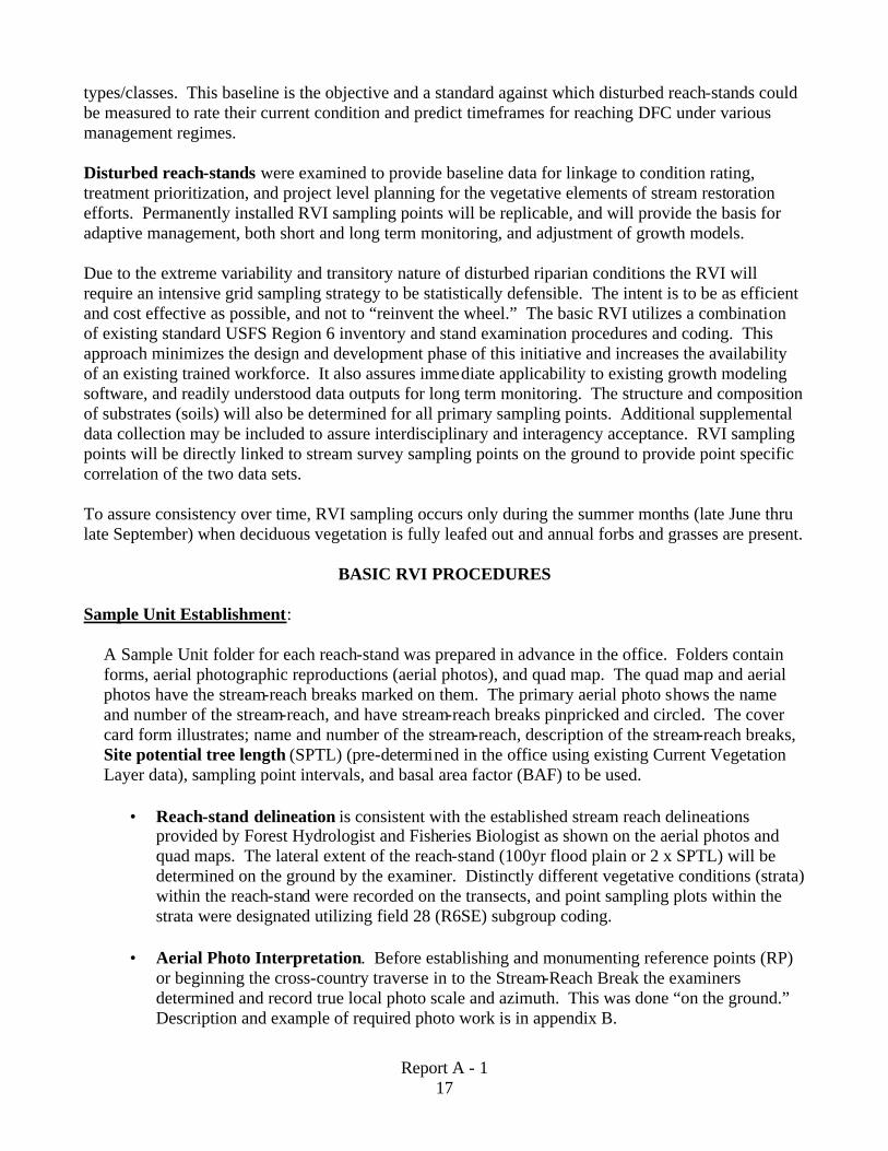
A Sample Unit folder for each reach-stand was prepared in advance in the office. Folders contain forms, aerial photographic reproductions (aerial photos), and quad map. The quad map and aerial photos have the stream-reach breaks marked on them. The primary aerial photo shows the name and number of the stream-reach, and have stream-reach breaks pinpricked and circled. The cover card form illustrates; name and number of the stream-reach, description of the stream-reach breaks, Site potential tree length (SPTL) (pre-determined in the office using existing Current Vegetation Layer data), sampling point intervals, and basal area factor (BAF) to be used.
• Reach-stand delineation is consistent with the established stream reach delineations provided by Forest Hydrologist and Fisheries Biologist as shown on the aerial photos and quad maps. The lateral extent of the reach-stand (100yr flood plain or 2 x SPTL) will be determined on the ground by the examiner. Distinctly different vegetative conditions (strata) within the reach-stand were recorded on the transects, and point sampling plots within the strata were designated utilizing field 28 (R6SE) subgroup coding.
• Aerial Photo Interpretation. Before establishing and monumenting reference points (RP)
or beginning the cross-country traverse in to the Stream-Reach Break the examiners determined and record true local photo scale and azimuth. This was done “on the ground.” Description and example of required photo work is in appendix B.

18
Report A - 1
Relocation documentation:
On the cover card, record driving/road system directions from the Ranger Station to the RP including odometer distances from landmarks such as road intersections, bridges etc. All Stream Reach Breaks, Reference Points (RPs), Points of Beginning (POBs), and Primary Sampling Points (PSPs) must be properly referenced and monumented on the ground to enable ready relocation at the time of the next survey. GPS coordinates will be recorded for these points, however GPS alone cannot be relied upon for specific point relocations on the ground.
RP’s, and POB’s shall be pinpricked on the primary aerial photo by the examiner. On the back of the photo, in permanent ink, draw a triangle around RP pinpricks and draw a square around POB pinpricks. Also record, on BOTH the cover card form and on the back of the photo:
• Date; • Examiners names; • Description of and GPS coordinates for the RP,(e.g: 20” dbh TSHE @ top of cut bank); • Distance and azimuth from the RP to the Reach Break; • Description of and GPS coordinates for the Reach Break monument; • Distance and azimuth from the Reach Break monument to the POB, and • Baseline transect azimuth from the POB to PSP#1.
Monumenting Points:
The RP provides a known point from which the reach break can be relocated on the ground by traverse. Establish and monument the RP above the flood plain at the closest or easiest walk-in access point. Objects selected as RPs must be easily identifiable, re-locatable ten years after establishment, and accessible on the ground. Mark the RP with 6 (six) inch wide band or blaze of orange paint at or above eye level facing the likely avenue of approach, place an aluminum information reference tag one 1 ft. above the ground line on the opposite side. Scribe on the tag:
• “RP” • Reach Name and Number; • Distance in feet (horizontal) from RP to Reach Break; • Azimuth from RP to Reach Break; • Date.
The Stream Reach Break is the delineation of a change in stream flow and or channel characteristics determined by the Hydrologist or Fisheries Biologist. Reach Breaks are normally relatively easily identifiable such as the confluence of major tributaries, waterfalls, bridges, etc. Establish the Reach Break monument above the normal bank-full point. Drive a 3 ft long piece of orange painted rebar into the ground leaving 1 ft. exposed, or in bedrock channel types select and paint a well anchored outcrop of rock. The POB is where the baseline transect will begin. POB’s will be established by the examiner at a distance of one SPTL from the bank-full point of the low flow channel and approximately at a 90 degree right angle to the stream course. Drive a 3 ft long piece of orange painted rebar at the POB and establish 2 (two) or 3 (three) Supplemental Reference Points (SRPs) as close as possible to

19
Report A - 1
POB, which roughly triangulate the POB. Mark SRPs with a 6 (six) inch blaze of paint facing POB at eye level, and nail a circular aluminum tag (facing POB) at the base 1 (one) foot above the ground line. Scribe on the tags:
• “SRP” # (1, 2 etc.) • Distance in feet and 10ths of a foot (horizontal) from aluminum SRP tag to the POB; • Azimuth from SRP to the POB;
PSPs are the primary sampling points. PSP plot centers will be monumented with an orange painted 2”x2” cedar stake driven into the ground. Establish 3 (three) SRPs as described above. If no suitable trees, stumps or other objects are available as SRPs use additional cedar stake(s) and note in plot remarks. Scribe on the tags:
• “SRP” # (1, 2 etc.); • “PSP” # (1,2 etc.); • Distance in feet and 10ths of a foot (horizontal) from aluminum SRP tag to the PSP; • Azimuth from SRP to the PSP.
“Quick Plots” are taken at predetermined intervals along baseline and lateral transects between the PSPs. Quick plot centers will be marked with plastic flagging only.
Data Collection:
A Baseline Transect will be established from the POB on a recorded azimuth running parallel to the stream channel. Downed Woody Debris (DWD) intersecting the transect will be recorded. Primary Sampling Points (PSP’s) and “Quick Plots” will be established at intervals along the baseline transect. At each PSP the examiner will adjust the azimuth of the transect to maintain the APPROXIMATE SPTL distance from the channel. Changes in azimuth will be recorded on the plot card. Primary Sampling Points (PSP), beginning at one half the established interval from the POB, PSP’s will be established at the pre-determined interval along the baseline transect. The standard interval will be 5 (five) chains (330ft.). Data collection for PSP’s will be conducted using standard Region 6 type 20 stand exam procedures and be recorded on standard stand exam cards. Substrates (soils) will be determined by coring, be classified as to type and composition as described and published in Riparian Ecological Types [for] Gifford Pinchot and Mt. Hood National Forests (R6-NR-TP-10-96), and recorded on supplemental “soils card”. PSP’s will be monumented on the ground for relocation, and their GPS coordinates recorded on the plot card. Lateral Transects will be run at right angles (90 deg) from the baseline transect at each PSP. One lateral will extend to the “bank-full” point of the low flow channel and one to the outer edge of the reach-stand. DWD intersecting the transect will be recorded. A flag (with the plot number of the PSP from which the transect originates and the azimuth) will be tied at the point the transect reaches the bank of the channel. This will allow stream cross sections to be measured and recorded by stream survey crew at the same location and azimuth, and provide an exact link between the two data sets.

20
Report A - 1
Quick Plots: Region 6 type 12 (regeneration exam) with card 4 fields (cover type) 1/100th acre fixed radius plot. Beginning at the POB, Quick plots will be established along the baseline (between the PSP’s) and along lateral transects, at a pre-determined interval. The standard interval will be 110 ft. On lateral transects, in addition to the standard interval, a quick plot will be established at the end of both transects. Photo Point Documentation: Photo points will be established at POB, PSP’s, and where the lateral transects reach the channel. The photo will be “shot” from the point looking down the transect at eye level. At the channel, photos will be shot both looking back down the transect and looking “out” across the channel at the same azimuth as the transect.

21
Report A - 1
Results
Riparian Vegetation Surveys
David Doede
Gifford Pinchot National Forest Geneticists
Data sets consist of vegetation data collected in a Current Vegetation Survey (CVS) format. Sample units for woody vegetation and down woody material are 1/5th acre transects stratified into lower and upper riparian vegetation types. Three reaches along 3 different streams were sampled, 2 undisturbed reaches (Trout Cr., TC, and Wind River, WR) and 1 disturbed reach (Crater, CR). All 3 streams had plots in the lower riparian strata, only the 2 undisturbed streams had plots in the upper riparian strata.
The question of interest is to compare and contrast the vegetation of the disturbed reach with that of the 2 undisturbed reaches. Comparisons are drawn first for woody vegetation of lower riparian types, then for grasses, forbs, and brush species. Summaries are provided for data from upper riparian strata for the undisturbed streams, but contrasts with the disturbed treatment are not possible.
Parameters were estimated and reported by diameter classes (see table below for diameter ranges). These diameter ranges were chosen arbitrarily, and do not necessarily have any biological meaning.
Diameter Class 1 2 3 4 Diameter Range 0-5.99” 6.0”-11.99” 12.0”-29.99” 30.0” +
Results Summary
• Trees at the disturbed site, CR, are much younger than trees at TC and WR (Table 1, Figure 4). Maximum age at CR is 110, overall median=49, whereas maximum age at TC and WR is 450, median=135 and 151 respectively. This difference determines to a large extent the many other differences among the sites.
• Density and diameter class distribution are very similar for the 2 undisturbed sites (Table 2, Figure 5). Although total live tree stocking is similar between disturbed and undisturbed sites, there are significant differences in distribution across diameter classes. 1) TC and WR have significantly more large trees (diameter classes 3 and 4) than TC (p<.05). 2) Conversely, CR has significantly more trees in diameter class 2 than TC and WR (P<.05).
• CR actually has more total snags per acre than TC and WR (p<.05) (Table 2, Figure 5). Snags per acre are similar for diameter classes 1,2,and 3, however CR has more in the largest diameter class. Probably these are ‘legacy trees (or snags)’ left from a stand-renewing disturbance. There is a trend for snag height to be taller at WR and TC, but there is too much variability to quantify the difference beyond that.
• The undisturbed sites have significantly more ACMA, THPL, and TSHE than the disturbed site (p<.05), and CR has significantly more ALCU than TC and WR (p<.05) (Table 3, Figure 6). THPL was the most frequent species in the largest diameter class at TC and WR, and PSME only occurred in the largest class at these 2 sites. ALRU was the most frequent species in class 2 at all sites.

22
Report A - 1
• Median growth rates at CR are roughly 1” radial increase per decade, approximately double the median growth rates at TC and WR (Table 4, Figure 7). Tolerant species at TC and WR seem to be growing faster than early seral species, such as PSME, and THPL is consistently one of the top performers at all sites.
• Crown ratios at TC and WR are well distributed among crown class groups, and there are suppressed, intermediate, co-dominate, and dominate trees present (Figure 8). This should indicate good competition between individuals and stand development at the site. At CR there are proportionately more trees with large or very large crowns, and fewer suppressed and intermediate class trees. This, and high growth rates, indicate the trees have not yet started to compete with each other much at this site.
• CR had the least damage of all sites, only 1.2% of the trees had been damaged by insects (Table 5). WR had the least damage of the undisturbed sites, 92.7% were undamaged, and TC had the most damage (75.9% were undamaged). At both TC and WR the most frequent damage class encountered was poor form (fork, crook, lean, sweep, bole cracks, and unspecified bole damage), 13.8% and 4.8% respectively. Possible explanations for TC sustaining more damage than WR include: 1) perhaps sanitation treatments were applied at WR but not at TC; and 2) WR may be at a more benign or protected geographic location than TC is.
• All three sites appear to have similar amounts and average sizes of down woody material (Table 6, 9.5 – 13.0 pieces per acre), although the range of sizes and size of the largest piece is greater at the undisturbed sites.
• Seedling and sapling occurrence was very clumpy and uneven, and the sample size for these estimates is not large; consequently there are large standard errors around all estimates of regeneration (Table 7). The undisturbed sites had the highest regeneration estimates. TC had an estimated 4002 TPA, of which 87% were conifers. The estimate for WR was 2510 TPA of which 51% was hardwoods and 49 % conifers, and at TC the estimate was 1851, of which 61% was hardwoods and 39% conifers. Conifer regen was mostly ABAM, ABGR, and TSHE, with smaller amounts of THPL. PSME amounts were very low at all sites. Hardwood regen was predominately ALRU, with some SALIX and ACMA (particularly at TC site).
• Cover estimates of major cover groups (Table 8) do reinforce some trends noted from above data; TC site has the highest estimated percent cover of trees<.9” DBH (most amount of regen), and all three sites have similar estimates for down woody debris cover (similar amounts per acre of down woody debris). CR site had more duff and fewer forbs than TC and WR; estimates for grass were uniformly low at all sites. Estimates of large and small rock were also similar among sites, and all sites had at least twice as much small rock as large rock. All sites also had twice as much tall shrub (>3’) cover as short shrub (<3’) cover, CR and WR had comparable amounts but the TC site was considerably brushier.
• Using tables 8 and 9, sites were classified using the key in ‘Riparian Ecological Types, MT hood, Gifford Pinchot N.F.’s and Columbia Gorge Scenic Area’. CR keyed out as an ALRU/TOMI-MOSI association (possibly an early seral stage of a Western Hemlock association); TC keyed out as a ABAM/TIUN association; and WR keyed out as a TSHE/OPHO/OXOR association. This process used average values from multiple plots, not strictly the accepted procedure for classifying plant communities.

23
Report A - 1
Tables and Figures Table 1. Median, minimum, and maximum ages by diameter class for CT, TC, and WR.
Lower Riparian Diameter Classes Upper Riparian Diameter Classes Site 1 2 3 4 1 2 3 4 CR 42,42,42 40,18,110 70,45,100
TC 77,23,135 143,65,227 230,96,450 61,24,133 138,40,235 152,88,234 260,170,339)
WR 90,35,148 151,30,300 288,140,450 120,120,120 165,140,165 453,306,600
Table 2. Density of snags and live trees for Crater (CR), Trout Cr. (TC), and Wind R. (WR sites.
TPA (SE) by Diameter Class Site (transects) 1 2 3 4 Total
Lower riparian, live trees CR(6) .8(.8) 62.5(15.7) 13.3(4.4) 0 76.7(19.1) TC(12) 1.6(1.3) 19.2(6.6) 23.8(4.7) 22.5(3.3) 67.1(9.3) WR(10) 0 29.0(4.8) 30.5(4.9) 23.0(3.6) 82.5(8.1) Lower riparian, snags CR(6) 0 3.0(2.0) 7.0(1.2) 14.0(2.4) 24.0(3.7) TC(12) 0 2.3(1.0) 6.4(.7) 9.1(2.0) 17.7(2.5) WR(10) 0 2.2(1.2) 7.8(1.9) 3.9(1.4) 13.9(2.2) Upper riparian, live trees CR(0) - - - - - TC(7) 10.7(5.4) 27.9(4.7) 44.3(8.0) 30.0(6.0) 112.9(8.8) WR(1) 0 30 40 20 90 Upper riparian, snags CR(0) - - - - - TC(7) .7(.7) 8.6(2.4) 15(4.9) 10.7(3.0) 35.0(6.9) WR(1) 0 5 10 10 25 Table 3. Species distribution (in TPA) for sites. Species acronyms follow CVS conventions. (First 2 letters of genus name followed by first 2 letters of species name.)
SPECIES SITE ABAM ABGR ABPR ACCI ACMA ALRU PSME SPE1 TABR THPL TSHE CR 5.0(5.0) 5.0(3.2) 4.2(2.4) .8(.8) 38.3(9.0) 5.8(3.7) 5.0(2.6) 13.3(6.8)
TC 3.3(1.7) 2.5(1.0) .4(.4) 9.2(5.9) 3.8(1.8) 1.7(1.7) .4(.4) 22.5(3.3) 23.3(8.1)
WR 1.0(1.0) 12.0(3.7) .5(.5) 16.5(4.8) 13.0(4.2) 4.5(2.3) 7.0(3.3) 12.0(3.2) 16.5(6.0)
TC 17.1(4.9) 2.9(1.5) 2.4(1.5) 5.0(1.9) 1.4(1.4) 22.9(6.7 61.4(8.8)
WR 10.0 5.0 75.0

24
Report A - 1
Table 4. Median, minimum, and maximum growth rates (10 year radial growth in 20ths of an inch) by diameter class for CT, TC, and WR.
Lower Riparian Diameter Classes Upper Riparian Diameter Classes Site 1 2 3 4 1 2 3 4 CR 10,10,10 20,7,26 20,10,28 TC 10,10,10 6.5,1,22 8,1,26 9,6,24 7.5,2,21 5,2,15 7,1,27 7,2,24 WR 6.5,1,18 8,3,25 12,4,21 15,15,15 5,3,13 6.5,2,11 Table 5. Percent damage by damaging agent for CR, TC, and WR sites. Site None Bad Top Poor Form Insect Stem Rot Lower Riparian CR 98.8 1.2 TC 75.9 8.0 13.7 0.6 1.8 WR 92.7 1.2 4.8 1.7 1.2 Lower Riparian TC 57.5 7.0 17.7 1.2 16.4 WR 88.9 11.1 Table 6. Mean number of down woody material pieces per acre (SE) and average piece size (min, max). Site Mean per acre (SE) Diameter (in) (min, max) Length (ft) (min, max) Lower Riparian CR 11.3 (2.4) 18.8 (6,45) 17.3 (5,40) TC 9.5 (1.2) 20.1 (6,60) 24.2 (6,95) WR 13.0 (1.5) 15.7 (4,60) 22.5 (5,60) Upper Riparian TC 13.1 (2.6) 17.3 (3,42) 23.2 (6,85) WR 19.0 12.2 (5,27) 20.7 (6,52)

25
Report A - 1
Table 7. Density and frequency (proportion of plots) of seedlings and saplings. (SE in parentheses)
Lower Riparian Upper Riparian CR site (n=12) TC site (n=28) WR site (n=20) TC site (n=4) WR site (n=1)
Species TPA (SE) Freq TPA (SE) Freq TPA (SE) Freq TPA (SE) Freq TPA(SE) Freq ABAM 389 (386) .36 15 .05 8050 (6229) .75 300 1.0 ABGR 17 .08 1596 (922) .46 640 (280) .5 1600 (759) .75 1000 1.0 ACMA 350 (148) .35 ALRU 1125 (340) .5 521 (199) .64 850 (410) .25 75 .25 POTR2 33 .08 PSME 117 .08 57 (97) .12 20 (13) .15 225 .25 SALIX 70 .05 TABR 18 .06 THPL 167 (59) .58 107 (66) .32 300 (132) .45 400 (212) .5 TSHE 392 (299) .33 1314 (864) .57 265 (195) .40 11625 (4026) .75 1700 1.0 Table 8. Mean percent cover estimates (SE) and frequencies for major cover groups.
Lower Riparian Upper Riparian CR site (n=12) TC site (n=28) WR site (n=20) TC site (n=4) WR site (n=1)
Cover Class *
%COV (SE)
Freq %COV (SE)
Freq %COV (SE)
Freq %COV (SE)
Freq %COV (SE)
Freq
DUFF 29 (7) 1.0 16 (4) .64 14 (3) .90 50 (16) .75 30 1.0 FORB 22 (6) 1.0 40 (5) .75 43 (6) .90 28 (10) .75 70 1.0 GRASS 5 .08 2 (2) .07 .1 .05 LROCK 6 (3) .41 3 (2) .46 5 (2) .45 MOSS 20 .25 SAND 5 (4) .12 .1 .05 SROCK 12 (6) .58 13 (3) .39 15 (6) .45 SSHRUB 6 (1) 1.0 10 (3) .71 4 (1) .85 21 (9) .75 1 1.0 TSHRUB 15 (3) 1.0 25 (4) .79 11 (2) .95 9 (2) .50 25 1.0 TREE 10 (5) .8 26 (20) .71 6 (1) .85 55 (6) .75 12 1.0 WATER 14 (5) .5 15 (3) .46 6 (5) .35 WOOD 2 (2) .5 1 .04 3 (3) .20 * DUFF=Duff; FORB=Forbs (all species); GRASS=Grass (all species); LROCK=Large Rock; MOSS=Moss (all species); SAND=Sand; SROCK=Small Rock; SSHRUB=Short Shrubs (<3’);TSHRUB=Tall Shrubs (>3’); TREE=Trees<.9’DBH (all species); Water=Water; Wood=Down Wood Debris.

26
Report A - 1
Table 9. Mean percent cover estimates (SE) and frequencies for indicator species.
Lower Riparian Upper Riparian CR site (n=12) TC site (n=28) WR site (n=20) TC site (n=4) WR site (n=1)
Species %COV Freq %COV Freq %COV Freq %COV Freq %COV Freq ACCI 7 1.0 23.2 .89 6.8 .7 2.0 .50 7.0 ACTR 6.0 .68 <1 .5 18 1.0 5.0 ADBI <1 .36 <1 .75 <1 .25 1.0 ADPE <1 .45 ANDE <1 .25 <1 .35 <1 .25 3.0 ANMA .25 .25 ASCA3 .25 .67 <1 .57 <1 .65 ATFI .9 .83 <1 .36 <1 .50 <1 .25 BENE <1 .25 <1 .25 BLSP <1 .25 <1 .25 CIAL 1.0 .43 <1 .60 CIUN <1 .25 CLUN <1 .29 <1 .75 3.0 COCA <1 .25 1.7 .32 <1 1.0 <1 COCO <1 .25 DIFO <1 .25 <1 .36 DIHO <1 .25 GATR <1 .5 <1 .54 1.3 .85 <1 GOOB <1 .25 GYDR 1.3 .58 3.1 .39 1.6 .7 1.5 .25 LAMU <1 .25 1.3 .6 LIBO2 <1 .25 <1 LOHI <1 MASI <1 .25 MEFE <1 .50 MOSI <1 .46 1.7 .8 OPHO <1 .50 2.0 .6 OXOR 1.3 .39 3.7 .25 PEFR2 <1 .4 POMU <1 .42 <1 .64 <1 .7 <1 .25 <1 ROGY <1 .29 <1 .50 RUNI <1 RUPA 1.6 .83 1.1 .29 <1 .45 <1 .25 RUSP 7.8 .91 1.6 .25 1.2 .65 <1 .25 RUUR <1 .33 <1 .25 <1 .25 <1 SMST <1 .33 1.5 .71 1.3 .25 STAM <1 .33 <1 .35 STCO4 <1 .75 <1 .5 TITRU 4.4 .68 1.0 .65 <1 .75 4.0 TOME 2.8 .67 4.8 .6 TROV <1 .75 1.0 VAAL 2.5 .36 37 1.0 VAHE <1 .33 2.9 .71 1.1 .65 4.8 .75 1.0 VAME 2.5 1.0 VAPA <1 .25 <1 .5 VIOLA <1 .79 <1 .55 <1 .75 2.0

27
Report A - 1
Figure 4. Mean age by species for lower and upper riparian areas at CR, TC, and WR sites.

28
Report A - 1
Figure. 5. Average live and snag TPA (error bars are 80% confidence intervals) by diameter class for 3 sites (2=Crater, 3=Trout Cr., 4=Wind R.).

29
Report A - 1
Figure 6. Species distribution (in trees per acre) for lower and upper riparian areas at 3 sites. (CR=Crater, T=Trout Cr., and W=Wind River.)

30
Report A - 1
Figure 7. Mean growth rate by species for lower and upper riparian areas at CR, TC, and WR sites.

31
Report A - 1
Figure 8. Crown ratio distribution of sample trees at lower and upper riparian areas at CR, TC, and WR sites.

32
Report A - 1
Notes and Discussion Age (Table 1, Figure 4)
• Maximum ages at CR are 110 and 100, so the disturbance probably happened just prior to 1900. Average ages by species are somewhat less, 30 – 68, indicating restocking has occurred over an extended time period. There are no definite patterns among species at this site, although mean age for TSHE is a little older than the other species. Unfortunately there is no age data for ALRU, and impossible to tell if it established in a similar pattern as the other species.
• TC and WR sites have fairly similar age distributions, however there are some differences by species.
• PSME has the oldest mean age in the lower riparian areas at TC (241 years). The other species seem to have established somewhat later, grouping at 114 – 164 years of age. Surprisingly, ABGR is the oldest species in the upper areas at this site (274). PSME, THPL, and TSHE have moderate ages (161-205), and ABAM and TABR are relatively young (118-132). Some of this may be an artifact of sampling, ages were not obtained on all trees, particularly old, rotten ones (TSHE).
• PSME, TABR, and THPL have the oldest mean ages in the lower strata at WR (238-300). ABGR and TSHE are somewhat younger (121-168). It appears ACMA established fairly recently, on the average about 60 years ago. PSME is the oldest species in the upper strata (375), with THPL and TSHE establishing somewhat later (120-188). Once again, these results may have some sampling bias in them (see comment above).
Density (Table 2, Figure 5)
• Trout Cr. (TC) and Wind R. (WR) sites have very similar snag and live stem densities (Table 1 and Fig. 4). T-tests found differences for only one diameter class (Lower riparian snags, class 4; p=.06). Stocking levels are also fairly similar across diameter classes.
• Due to TC and WR being so similar, they were combined for t-test comparisons with CR.
• Total live stocking at CR is not significantly different from total stocking at TC/WR (p=.25), indicating the sites are comparably stocked with trees.
• For snags, total stocking is different (p=.05), with CR having the higher level. Were snags intentionally created and left after harvest at CR? Or were trees left for a riparian buffer and then they died?
• CR has significantly higher stocking in diameter class 2 (p=.06). This site was recently disturbed (relative to the other two), consequently the age (therefore size) of any stems is limited to the approximate diameter class (truncated distribution).
• TC/WR have significantly higher stocking in classes 3 and 4 (p=.06 and .0001 respectively). See comments above for diameter class 2.
• For snags, diameter class 4 is the only significant difference (p=.02). see earlier comment on snag stocking levels.
33
Report A - 1
• These results are consistent with the observation that CR site has been recently disturbed and TC and WR are relatively undisturbed.
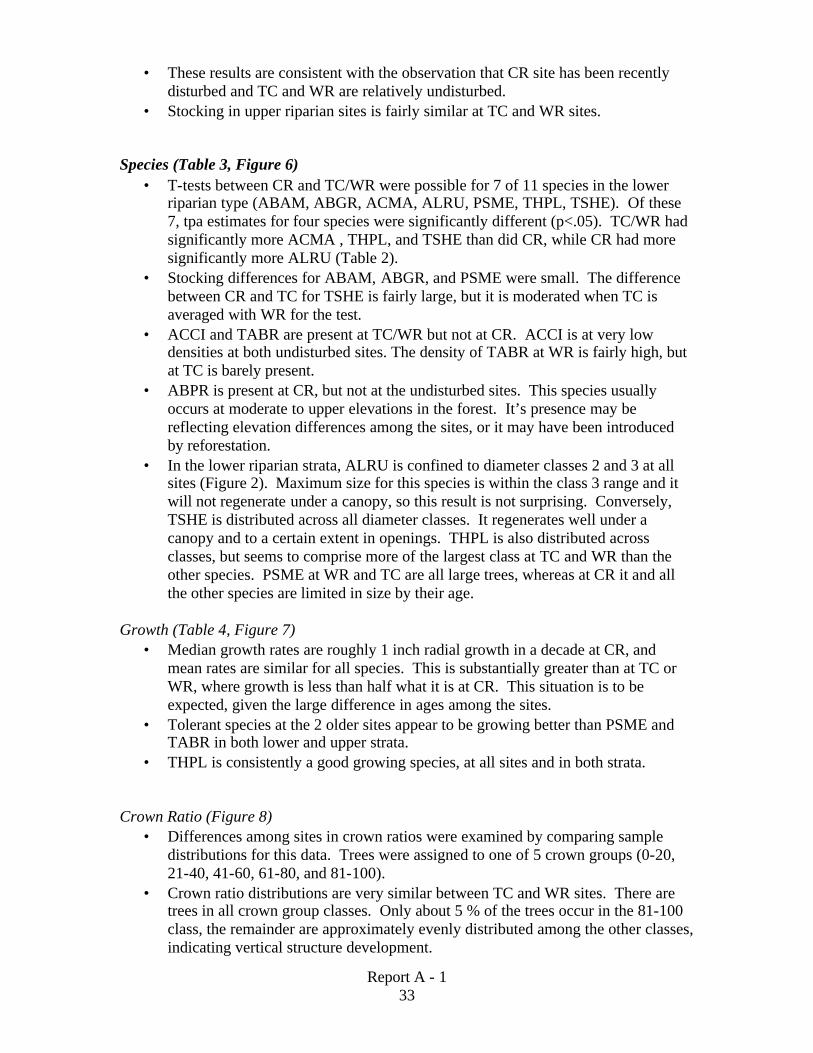
• Stocking in upper riparian sites is fairly similar at TC and WR sites. Species (Table 3, Figure 6)
• T-tests between CR and TC/WR were possible for 7 of 11 species in the lower riparian type (ABAM, ABGR, ACMA, ALRU, PSME, THPL, TSHE). Of these 7, tpa estimates for four species were significantly different (p<.05). TC/WR had significantly more ACMA , THPL, and TSHE than did CR, while CR had more significantly more ALRU (Table 2).
• Stocking differences for ABAM, ABGR, and PSME were small. The difference between CR and TC for TSHE is fairly large, but it is moderated when TC is averaged with WR for the test.
• ACCI and TABR are present at TC/WR but not at CR. ACCI is at very low densities at both undisturbed sites. The density of TABR at WR is fairly high, but at TC is barely present.
• ABPR is present at CR, but not at the undisturbed sites. This species usually occurs at moderate to upper elevations in the forest. It’s presence may be reflecting elevation differences among the sites, or it may have been introduced by reforestation.
• In the lower riparian strata, ALRU is confined to diameter classes 2 and 3 at all sites (Figure 2). Maximum size for this species is within the class 3 range and it will not regenerate under a canopy, so this result is not surprising. Conversely, TSHE is distributed across all diameter classes. It regenerates well under a canopy and to a certain extent in openings. THPL is also distributed across classes, but seems to comprise more of the largest class at TC and WR than the other species. PSME at WR and TC are all large trees, whereas at CR it and all the other species are limited in size by their age.
Growth (Table 4, Figure 7)
• Median growth rates are roughly 1 inch radial growth in a decade at CR, and mean rates are similar for all species. This is substantially greater than at TC or WR, where growth is less than half what it is at CR. This situation is to be expected, given the large difference in ages among the sites.
• Tolerant species at the 2 older sites appear to be growing better than PSME and TABR in both lower and upper strata.
• THPL is consistently a good growing species, at all sites and in both strata. Crown Ratio (Figure 8)
• Differences among sites in crown ratios were examined by comparing sample distributions for this data. Trees were assigned to one of 5 crown groups (0-20, 21-40, 41-60, 61-80, and 81-100).
• Crown ratio distributions are very similar between TC and WR sites. There are trees in all crown group classes. Only about 5 % of the trees occur in the 81-100 class, the remainder are approximately evenly distributed among the other classes, indicating vertical structure development.

34
Report A - 1
• Crown group distribution is different at the CR site, there are no trees in the 0-20 group and a much higher percentage of trees in the 81-100 group (approx. 20%). The 60-80 group has by far the most trees at this site (approx. 40%). This stand is much more uniform vertically than the 2 undisturbed sites.
• Crown ratios are also similar between the TC and WR sites in the upper riparian areas, with no trees in the 80-100 group and the most trees in the 0-20 group. Vertical structure is well developed in this stratum also.
Defect and form (Table 5)
• For the purposes of this report, damage classes include bad top (broken, missing or dead top); insects (mostly bark beetles); poor form (fork, crook, lean, sweep, bole checks or cracks, and unspecified bole damage); and stem rot (red ring rot, Indian paint, brown cubical rots).
• TC sustained the most damage of the three sites. Poor form was the most frequent damage code in both strata. Bad top and insect codes were encountered approximately equally in both strata, while stem rot was much more frequent in the upper stratum and contributed to the difference in total damage between strata.
• WR site has less damage than TC. Possibly it is located in a more favorable and benign geographic position, or had sanitation treatments applied to it (?). Only minor amounts of all damage codes were encountered at this site.
• CR was the least damaged of the sites, with nearly 99% undamaged. Insect damage was the only code recorded at CR.
Down woody material (Table 6) All three sites have similar amounts of down woody material (9.5-13.0 pieces per acre) and the sizes are surprisingly similar. The disturbance event at CR does not seem to have affected this variable much at all (assuming the sites were similar prior to the disturbance). Regeneration (seedlings and saplings) (Table 7)
• Seedlings and saplings 6” high to .9”DBH were recorded on 1/100th acre plots. 2 plots per lower riparian transect were taken and 1 plot per upper riparian transect was taken. Sample size is very small and distribution of these trees is very clumpy and uneven, as a result standard errors of estimated mean TPA is very high, sometimes larger than the estimate itself. Frequency is also reported because it is robust to outliers and still shows trends.
• In the lower strata at all three sites the most commonly encountered species are ALRU, THPL, and THSE. Also, frequency and TPA estimates of PSME were low for this strata at all sites.
• ABAM and ABGR are more frequent and abundant at WR and TC than at CR. Salix is found on 1 plot at WR and TABR is found on 1 plot at TC.
• The upper riparian strata at both TC and WR sites are dominated by tolerant conifers (ABAM, ABGR, THPL, and THSE).
Percent cover of cover types (Table 8)
• Data was collected on the same plots as the seedling and sapling data and similar caveats about standard errors and sample size apply.

35
Report A - 1
• In the lower strata, mean estimates and frequencies for most cover classes are fairly similar. Grass occurs at very low frequencies and low amounts. Large and small rock is distributed on about half the plots, with large rock in very small quantities and there being somewhat more small rock. Trees and tall and short shrubs are common at all three sites, although TC has more brush than the other two. Standard errors for tree estimates are high in relation to the estimates, probably due to patchy, uneven distribution as mentioned above. Water occurred relatively often, but did not cover a large area. Similar to results from the fifth acre plots, down woody material has similar estimates for all sites, albeit they seem like low values.
• Three classes that stand out as being different among sites are DUFF, FORB, and SAND. CR site has more duff, possibly due to material deposited on the ground during the disturbance and then decaying (?). TC and WR sites have more forbs, probably due to the lack of disturbance at these sites. Sand does crop up infrequently and have low cover estimates at WR and TC, but is not present at CR.
• There appears to be two large differences between TC and WR in the upper strata: 1)WR has a higher estimate for tall shrubs than TC, however this is suspect because sample size is so small and the trend in the lower stratum is just the opposite. 2). TC has more trees and short shrubs, and while this follows the trend in the lower stratum, the sample size is very small.
Indicator species (Table 9)
• Species listed only if frequency is .25 or greater. • Generally, the standard errors associated with these estimates were quite high,
often as great or greater than the estimate itself. • The average values from tables 8 and 9 were used to work through the key in
Riparian Ecological Types, Gifford Pinchot and Mt Hood National Forests, Columbia Gorge National Scenic Area. The keys are designed to apply to uniform, undisturbed areas sampled with a single 5 x 10 meter plot, and an ‘average type’ as defined by these mean values may not conform to the assumptions and methods used to develop the key. However, some insights into possible management activities and constraints may be gained by this exercise. The couplets in the key were generally easy to answer with the data on hand, however mean % cover values were generally low and frequency data was often used to infer dominance of a particular species.
• The process resulted in classifying the CR site to the ALRU/TOMI-MOSI or the ALRU/RUSP/TOME plant associations. The main difference between these two associations is the amount of shrub layer (break at 20% tall shrubs), and since this site has 15% tall shrub cover, it fits best in the TOMI-MOSI community. Generally, the description of landforms, channel type, and vegetation presented in the Riparian Ecological types seemed to fit with the data here. This site has some conifer regeneration, lending support to the idea presented under management implications that the association may be a successional stage of a Western Hemlock Zone conifer plant association.
• TC site is classified as an ABAM/TIUN plant association, primarily due to the presence of ABAM in the overstory and understory, and the amount of TITRU in the forb layer. The ACCI dominance is characteristic of this association.

36
Report A - 1
• The closest association for WR site is TSHE/OPHO/OXOR, however the amount of devil’s club is a bit low. Other than that, the association description seems to fit well.
Stream Channel Surveys Geomorphic channel surveys were conducted for Upper Trout Creek, “The Old Growth Reach” of Trout Creek, Crater Creek, Compass Creek, Pass Creek and Layout Creek. The data is in the process of being synthesized at the time of this report. The synthesized data will be used to design site-specific channel rehabilitation for the future restoration projects.

37
Report A - 1
1999-2002 Restoration Accomplishments
Riparian and Channel Rehabilitation
Figure 9. Locator map for the 1999 Wind River watershed restoration projects.
N
Scale 1:25000
1” = 4 Miles
Key Watershed Boundary Dry Creek Trout Cr. Phase IV Wind R. Mining Rch. Panther Creek Bnk Stab.
To Vancouver WA
Bonneville Dam

38
Report A - 1
1999 Trout Creek Restoration “Phase IV”
Figure 10. 1999 Trout Creek Restoration project site map, T.4N., R.6E. Section 13, Skamania County Washington.
N
Key LWD Bank Revetments Log Jam/Grade Control Log Complex Meander Reconstruction Old Growth Channel
Scale 1”=
Approximately 0.2 Miles

39
Report A - 1
“Trout 4” Trout Creek Flats Channel Rehabilitation, Phase IV
Project Lead: US Forest Service Cooperators: US Fish and Wildlife Service and Bonneville Power Administration. Location: T4N, R6E, Section 13 Goals: The goals of this project are to reduce water temperature maximums below lethal salmonid levels, restore riparian conifers, and reestablish bank and channel stability to recover viable populations of wild steelhead. Objectives: The objectives to meet these goals are: (1) reduce the width to depth ratios within identified reaches to less than 25 (2 years), (2) increase shade to greater than 80% (60 years) (3) increase bank stability above 80% (10 years), (4) restore the conifer component along these reaches to eight trees per acre greater than 31" in diameter (200 years), (5) increase in-stream large woody debris >100 pieces per river mile (1 year) and (6) maintain 0.8 river miles of old growth channel and historic flood plains. Project Actions: One-hundred and twenty blown down logs (half with attached root-wads) were salvaged and stockpiled in Trout Creek Flats. A heavy helicopter was used to fly the material to project areas. A tracked excavator constructed logjams and bank revetments with the wood to meet the previously mentioned objectives. Site specific placement of revetments and jams were based on templates derived from empirical data and analysis of undisturbed channels with similar characteristics. The head-gate sediment control structure that was placed to aggrade the channel in 1996 was removed to allow natural channel processes to occur. Status: Complete. U.S. Fish and Wildlife Service, Bonneville Power Administration and the USDA Forest Service have cooperatively funded this project. NEPA was completed in the winter of 1998. Materials were stockpiled in the fall of 1998, implementation began July 20th, 1999 and was completed August 20th, 1999. Narrative: Trout Creek is a major tributary of the Wind River and is vital for the recovery of wild summer run steelhead within the basin. The Trout Creek watershed has historically supported a significant percentage of the Wind Rivers run of wild steelhead yet composes 1/16th of the watershed area. Trout Creek Flats (river mile 6.5 to 9.0) was tractor logged in 1948. Re-vegetation efforts after logging failed apparently due to compacted soils. In the late 1960’s the entire flats area was “ripped” with heavy equipment to de-compact the soils and restore percolation. In the 1970’s log jams were thought to be migration barriers to steelhead. Log jams and other wood was removed or “cleaned” from stream channels. The removal of LWD eliminated the natural water velocity modification and sediment storage that the stream needed to function properly. The removal of wood from within the channel instigated serious channel degradation. The cumulative effect of removing streamside vegetation and in-stream LWD produced maximum water temperatures >75°F. Bank full channel width to depth ratios exceeded 60 on average with undisturbed reaches within the basin containing similar morphology possessed width to depth ratios of 25 on

40
Report A - 1
average. Stream shade was reduced to <27%, bank erosion rates were >40% and in-stream LWD levels were <40 pieces per river mile while undisturbed channels averaged 120 pieces per river mile within the watershed and loss of flood plains and side channel habitat. Accomplishments: This is the forth phase of the in-stream rehabilitation effort that began in 1992. This project treated river mile 6.7 to 8.0 in the Trout Creek Flats area. Approximately 200 pieces of LWD were placed into to 1.3 river miles. One hundred and twenty pieces were flown in by heavy helicopter and another 80 pieces were redistributed within the 100 year flood plain. One thousand-two hundred and twenty five feet of eroding bank were treated with large woody revetments. Twenty acres of flood plain were reclaimed with large woody aggradation structures (log jams). Seven hundred feet of degraded or down-cut channel was aggraded with log jams to the historic elevation. Seven-tenths of a river mile river mile of old growth channel were reactivated to increase stream shade within the reach from 26% to 41%.

41
Report A - 1
Photo 2. 1995 Photo of the entrance to the Trout Creek old growth channel, Skamania County, WA. A logjam that was thought to be a migration barrier was removed in 1981. The removal of the logjam initiated the channel to “down-cut” or degrade approximately five feet below the original bed elevation. As the channel degraded the connectivity with the flood plain and the last remaining old growth reach in Trout Creek. (Photos Bair)
Photo 3. 1999 Photo of the entrance to the Trout Creek old growth channel after restoration of logjam. Stream bed was aggraded over four feet to regain connectivity with flood plain and reactivate 0.8 of a river mile of pristine habitat.

42
Report A - 1
Photo 4. Photo of severe bank erosion on Trout Creek (river mile ~ 7.3) caused by removal of riparian vegetation, in-stream LWD removal and channel degradation. Skamania County, WA. (Photo Bair)
Photo 5. Photo of LWD revetment to reduce bank erosion. Trout Creek (river mile ~7.3), Skamania County, WA. (Photo Bair)

43
Report A - 1
Photo 6. Large width to depth ratios and low stream shade depicted in the above photo increase maximum water temperature and provide poor quality rearing habitat for steelhead. Trout Creek ~ river mile 7.1, Skamania County, WA. (Photo Bair)
Photo 7. Width to depth ratios were reduced by excavating pools and constructing gravel bars based on empirical hydraulic and geomorphic template data. Width to depth ratios for this photo sequence was reduced from 66 to 17. Trout Creek ~ river mile 7.1, Skamania County, WA. (Photo Bair)

44
Report A - 1
The “Mining Reach” Riparian and Channel Rehabilitation.
Figure 11. Upper project area river mile 25-23.5,of the Wind River, T6N, R7E, Sections 3,4,9 & 10, Skamania County WA.
N
Key LWD Bank Revetments Logjam/Grade Control Log Complex Meander Reconstruction Riparian Thinning
Reference Reach
Scale 1”= Approximately
0.18Miles

45
Report A - 1
The “Mining Reach” Riparian and Channel Rehabilitation.
Figure 12. Lower project area river mile 23.5-22 of the Wind River, T6N, R7E, Sections 9, 10, 16 & 21 Skamania County WA.
N
Key LWD Bank Revetments Logjam/Grade Control Log Complex Meander Reconstruction Riparian Thinning
Lower reach of project area will be completed in FY 00
Scale 1”= Approximately
0.18Miles

46
Report A - 1
The Mining Reach of the Wind River Riparian and Channel
Rehabilitation. (Project Lead USFS) Location: T6N, R7E, Sections 4,9,16 & 21 Goals: The goal of this project is to restore riparian function, riparian conifers, and reestablish bank and channel stability to recover viable populations of wild steelhead. Objectives: The objectives to meet these goals are: (1) restore the riparian conifer component along these reaches to eight trees per acre greater than 31" in diameter (200 years), (2) increase shade to greater than 80% (60 years) (3) increase bank stability above 80% (10 years), (4) reduce bankfull width to depth ratios within identified reaches to less than 25 (2 years), (5) increase in-stream large woody debris >100 pieces per river mile (70 years) and (6) Restore 32 acres of historic flood plains. Project Actions: Riparian areas were thinned and under planted with native conifers. Thinned trees were yarded into project sites with a tracked dozer and placed on exposed gravel bars, flood plains and eroding banks with a tracked excavator. Status: The project was completed on September 9st, 2000. USDA Forest Service “Flood Restoration dollars” and Bonneville Power Administration fish and wildlife monies funded this project. NEPA was completed in the spring of 1999, and implementation began August 16th, 1999. Three river miles were treated with >than 1,700 trees reintroduced into the reach. Narrative: The project area was railroad logged from late 1920’s to the mid 1930’s. The entire riparian area was denuded of its old growth. Riparian areas and channels have not recovered due to the lack of in-stream wood needed for velocity modification that protects young riparian stands from floods. The result has been an acceleration of lateral channel migration that has severely degraded water quality and fish habitat. Stream survey data and aerial photo analysis depict the problems found in the mining reach. Figures 3-6 show the existing channel conditions relative to the up-stream old growth reach and other similar undisturbed channels within the watershed. Large woody debris (>24” in diameter, >50’ in length) within undisturbed reaches averaged 120 pieces per river mile in the Wind River watershed. Within the Mining reach average LWD was 73 pieces per river mile (Figure 10). Riparian areas within the Mining reach are dominated with deciduous species such as alder, which will provide limited future LWD (Figure 11). Alder is an early successional species important to aquatic ecosystems. Alder typically reaches climax and die after 30 years. The dominance of alder within this reach 70 years after being logged indicates that channel disturbance has been frequent and the channel or riparian areas have not made significant progress in recovering. Analysis of belt widths provides additional evidence of accelerated disturbance and poor channel stability. Belt width is the width in which a stream contains its meanders. Belt widths in the up-stream section of the Mining reach are dominated with old growth timber. Belt widths within this reach averaged 60 meters compared to an average belt width of 145 meters in the

47
Report A - 1
logged reach just down-stream (Figure 12). Bank full width to depth ratios also provides evidence of poor channel stability and habitat conditions. Bank full width to depth ratios within the old growth Mining reach averaged 18. Down-stream in the logged reach bank full width to depth ratios averaged 62 (Figure 13). Accomplishments: Three river miles (RM) of steelhead spawning and rearing habitat within the Mining reach were treated (figures 8 & 9). Approximately 80 acres were thinned to increase stand vigor and diversity. Over 260 riparian acres have been under planted with 43,000 native conifers. Seventy-nine sites were treated with 1,700 pieces of LWD to protect riparian vegetation, reduce belt width, increase bank/channel stability and reconnect flood plains. Monitoring: Approximately 750 meters of channel were evaluated against established quantitative objectives to evaluate project. Objectives and Results:(1) restore the riparian conifer component along these reaches to eight trees per acre greater than 31" in diameter (200 years) and (2) increase shade to greater than 80% (60 years); Approximately 80 acres were thinned and under planted with 43,000 western red cedar and grand fir. Fourteen survival and growth plots have been established. These are long term objectives that will take decades to achieve. Monitoring and maintenance of planted trees will play a critical role in meeting objectives. (3) increase bank stability above 80% (10 years); bank stability in the evaluated reach increased from 33% to 91%. (4) reduce bank full width to depth ratios within identified reaches to less than 25 (2 years),; Bank full width to depth ratios decreased by 40%, from 87 to 51 and low flow width/depth ratios decreased 56%. This still falls short of our bank full objective of 25 but we expect a continued decrease of width to depth ratios as structures accumulate fines and scour pools. Pool volume increased by 520% which indicates that habitat conditions are heading in the right direction. (5) Increase in-stream large woody debris >100 pieces per river mile (70 years); LWD increased from 42 pieces per kilometer (67/river mile) to 210 pieces per kilometer (336/rivermile) as a result of treatment. (6) Restore 32 acres of historic flood plains. No data on this objective has been collected to date. However qualitative assessments of the project indicate that constructed log jams have arrested several areas of significant stream channel down cutting and multiple side channels have been reconnected during most winter flows.

48
Report A - 1
Mining Reach LWD
0
20
40
60
80
100
120
140
Instream LWD in DisturbedChannel (Pieces/Mile)
Average Instream LWD in Un-disturbed Alluvial Channels
(Pieces/Mile)
Pie
ces
of
LW
D p
er R
iver
Mile
Figure 13. Comparison of existing LWD observed in the Mining Reach and average LWD per river mile observed in 13 alluvial reaches of stream within Wind River, Skamania County Washington. LWD is defined as pieces >24” in diameter and >50’ in length.
Mining Reach
0
10
20
30
40
50
60
70
Large TreeMulti-Story
Large TreeSingle Story
Small Tree Hardwood Pole Seedling/Sapling
Figure 14. Percent composition of riparian stands* by seral class for the Mining Reach of the Wind River, Skamania County Washington.
* Riparian stands are delineated by the Aquatic Conservation Strategy standards; 360’ from bank full channel. Seral class definitions: Large tree = 48”-32” in diameter, Small tree = 32”-9” in diameter, Hardwood = alder, maple, cottonwood, Pole = 9”-5” in diameter, Seedling/Sapling = <5” in diameter, Large tree multi-storied is a mix of large and small class/ old growth.

49
Report A - 1
Figure 15. Comparison of belt widths in old growth and disturbed channels for the Mining Reach of the Wind River, Skamania County WA.
Figure 16. Comparison of the average width to depth ratios in old growth and disturbed channels for the Mining Reach of the Wind River, Skamania County WA.
Mining Reach Belt Width
0
20
40
60
80
100
120
140
160
Average Belt Width in OldGrowth Channel
Average Belt Width in DisturbedChannel
Me
ters
Belt Width 145 Meters
Belt Width 60 Meters
Mining Reach Width to Depth Ratios
0
10
20
30
40
50
60
70
Bankfull Width/Depth Ratio inOld Growth
Bankfull Width/Depth Ratio inDisturbed
Wid
th/D
epth
Rat
io Width/Depth Ratio = 18
Width /Depth Ratio = 62

50
Report A - 1
Photo 8. “Mining Reach” of the Wind River river mile ~24.3, Skamania County, WA. Photo Bair, August 1999. The logging that occurred in the early part of the century within the Mining Reach removed the natural lateral stability of the channel. Belt widths and width to depth ratios increased and as a result bank stability, stream shade, pools and cover have been greatly reduced.
Photo 9. “Mining Reach” of the Wind River river mile ~24.3, Skamania County, WA. Photo Bair, December 1999. This photo is taken in the same location as the one above to demonstrate how log complexes were installed to reconstruct meanders, restore sinuosity, lateral stability, width to depth ratios and restore historic belt width. In addition these structures scour pools and provide hiding cover for adult and juvenile steelhead.
Log Complexes
Deposition

51
Report A - 1
Photo 10. “Mining Reach” of the Wind River, mile ~24.7, Skamania County, WA. Photo Bair, July 1999. Lack of lateral stability promotes meander “cut-off” such as the one shown above. When the channel loses sinuosity channel slope and pool spacing increase, stream bed degrades and the channel becomes incised and drops out of the flood plain. Severe bank erosion ensues as the stream creates a new flood plain.
Photo 11. “Mining Reach” of the Wind River, mile ~24.7, Skamania County, WA. Photo Bair, August 1999. Logjams were installed as natural grade controls to aggrade the channel, restore sinuosity, flood plain connectivity, bank and channel stability.

52
Report A - 1
Photo 12. “Mining Reach” of the Wind River, mile ~24.0, Skamania County, WA. Photo Bair July 1999. Mass wasting from banks such as these can introduce very large quantities of coarse and fine sediment to spawning substrate in the reaches below.
Photo 13. “Mining Reach” of the Wind River, mile ~24.0, Skamania County, WA. Photo Bair August 1999. “Log terrace toes” were constructed at the bank full elevation to prevent undermining of the slope and reduce delivery of coarse and fine sediments.
“Log Terrace toe”

53
Report A - 1
Dry Creek Restoration
20012001
Project Lead: USDA Forest Service Project Cooperator: Bonneville Power Administration Location: Township 4 North, Range 7 East, Sections 20, 29 and 32. Goals: The goal of this project is to reduce the amount of fine sediment delivered to the Wind River through restoring riparian conifers, riparian function, and reestablishment bank and channel stability. Objectives: The objectives are: (1) restore the riparian conifer component along these reaches to 65-80 trees per acre with at least eight trees greater than 31” DBH (200 years), (2) increase shade to greater than 80% (60 years), (3) increase bank stability to greater than 80% (10 years), (4) reduce bankfull width to depth ratios in riffles to less than 25 (two years), (5) increase floodplain large woody debris to greater than 100 pieces per mile (70 years), (6) maintain a stable sinuosity (length of meander of 39 to 50 meters, belt width of 30 meters, radius of curvature of 11 meters, thalweg slope of 0.007 and a riffle slope of 0.02). Project Actions: Four gabions were removed from the site and replaced with two log structures composed of 15 logs five of which had attached root wads. Project Actions: Select areas of over stocked riparian stands were thinned to promote quicker growth and to “release” native conifers such as western red cedar. Areas were thinned in a herringbone pattern by means of pushing the trees over with a tracked excavator. Thinned trees were stockpiled and placed on exposed gravel bars, floodplains

54
Report A - 1
and used to construct logjams. The stream channel was created using a tracked bulldozer and excavator in unison to sculpt a channel and place large woody debris. Status: Implementation began on July 19, 2001. Project was completed on August 30, 2001. Narrative: The project area was railroad-logged beginning in the late 1920’s and continued through the mid 1930’s. By the time logging was completed, the entire riparian area had been denuded of its old growth conifers. Disturbed riparian areas and the channel have not recovered due to channel instability caused by channel incision and lack of large woody debris. Large wood is needed for velocity modification and bank protection, which protects young riparian stands from being prematurely recruited during peak events. The result has been an acceleration of lateral channel migration, which has severely decreased water quality by accelerating bank erosion. An old railroad crossing has also had significant impacts on Dry Creek. The old stream crossing, which is near the mouth of Dry Creek, constricted the channel and greatly reduced the channels bankfull cross-sectional area and ability to route and transport sediment. The combination of channel instability up-stream of this site and channel constriction resulted in aggradation of streambed upstream of the nick point and exacerbated lateral instability. Accomplishments: This project treated riparian areas and stream channels along river mile 0.4 to 1.1 and 2.3 to 3.9 of Dry Creek. Riparian areas along the disturbed reach were thinned to accelerate recovery of native conifer composition, structure and to provide a source of in-stream and terrestrial woody material. The stream channel was reconstructed and approximately 750 trees removed from the riparian area were placed in the bankfull channel and floodplain to reduce coarse and fine sediment deposition in Dry Creek and the Wind River. Approximately 150 trees were felled to increase terrestrial woody material. In addition, roughly 100 trees were girdled to provide snag habitat for wildlife.

55
Report A - 1
Figure 17. Dry Creek Restoration project site map; T.4N. R.7E. Sections 29 & 32, Skamania County, Washington.

56
Report A - 1
Figure 18. Dry Creek Restoration project site map; T.4N. R.7E. Section 20, Skamania County, Washington.

57
Report A - 1
Photo 14. Logjams were placed along eroding banks, gravel bars and floodplains to stabilize the channel and reduce erosion. Reach one of Dry Creek, T.4N. R.7E. Section 32, Skamania County, Washington. (Photo: Olegario)
Photo 15. Above: Before (left) and after (right) photos of log placement designed to reduce near bank shear stress on an eroded bend. Reach two, Dry Creek, T.4N. R.7E. Section 29 Skamania County, WA. (Photo: Powers/Olegario)

58
Report A - 1
“Panther Creek Bank Stabilization”
Project Lead: USDA Forest Service Location: T.4N., R.7E., NNW ¼ of Section 25 Goals: Prevent bank erosion and protect Panther Creek Campground Objectives: 1) Construct two log complexes and protect 175’ of eroding bank. 2) Create a pool greater than three feet in depth at low flow. Project Actions: Four gabions were removed from the site and replaced with two log structures composed of 15 logs five of which had attached root wads. Project Cost: Status: The project was completed in two days. Narrative: During the 1996 flood gabions designed to protect the bank bordering the Panther Creek campground were undermined and 175 feet of bank was severely eroded. The gabions were removed and replaced with log complexes to protect banks, scour pool and provide cover for juvenile and adult steelhead.
Photo 16. Panther Creek, river mile ~6.0, Skamania County, WA. Gabions were installed in 1980 to protect the Panther Creek campground. During the 1996 flood several were undermined and directing flows against unprotected banks. The gabions were removed and replaced with large tree structures to protect banks/campground, scour pools and provide cover for adult and juvenile steelhead.

59
Report A - 1
Task 4.c: Plant and thin riparian vegetation at select sites. (USFS)
“Riparian Rehabilitation”
Project Lead: US Forest Service Cooperators: Bonneville Power Administration. Project Location: T4N, R6E, Section 13 / T6N, R7E, Sections 4,9,16 & 21
Introduction Streamside vegetation was logged from late 1920’s to the mid 1980’s. Typically most riparian areas are over-stocked with homogeneous stands of hard woods such as red alder or Douglas fir conifers.
Methods
Densely stocked riparian stands were thinned to increase stand vigor and diversity and provide material for restoration projects. Wind River silviculturist selected climax species such as western hemlock and western red cedar that were present in the existing riparian stands. Trees surrounding the climax species were thinned or girdled to accelerate growth by reducing competition for sunlight and nutrients. Ten to twenty percent of all felled and girdled trees were left as down wood and snags to increase terrestrial, snag and roosting wildlife habitat. The other 80% of thinned material was used to rehabilitate floodplains and stream channels.
Stands of alder and Douglas fir were also under-planted with native conifers to increase stand diversity and provide a long-term source of large woody debris. Hand crews plant coniferous seedlings on 5 to 10 foot spacing during spring months. Rooted willow stock is planted on the lower banks and within the bankfull channel to increase channel stability and increase low flow stream shade. Western red cedar will be protected with brush and other debris to reduce browse from elk and deer.
Results and Discussion
During the 1999-2001 field seasons approximately 100 riparian acres have been thinned and 300 acres under-planted with approximately 56,000 native conifers in the Upper & Middle Wind River, Dry Creek and Trout Creek. Thinned trees were left on site or used in channel restoration treatments. Approximately 15 acres of rooted willow stock were planted on the lower banks and within the bankfull channel to increase channel stability and increase stream shade within Trout Creek, Dry Creek and the Wind River.

60
Report A - 1
Figure 19. Upper Wind River thinning and conifer planting project area, Skamania County, Washington, T5N, R7E, Sect. 9, 16.

61
Report A - 1
Figure 20. 1999 hardwood planting sites for Trout and Layout Creek, T4N, R6E, Section 13 Wind River watershed, Skamania County Washington.

62
Report A - 1
Figure 21. 2000-2002 planting site map for Dry Creek riparian reforestation project site map; T.4N. R.7E. Sections 20, 29 & 32, Skamania County, Washington.
Monitoring
Seventeen survival and growth plots were established for riparian plantings. Survival and growth will be evaluated on an annual basis for the next five years.

63
Report A - 1
Acknowledgements I would like to pay a special thanks to all of the U.S. Forest Service employees at both Mt. Adams Ranger District and Wind River Work and Information Center who have contributed to the restoration of the Wind River watershed. In particular and in no particular order: Anthony Olegario, Greg Robertson, Betty Hebert, Paul Powers, Eric Plimmer, Cathy Flick, James Umtuch, Jim Nielsen, Steve Ohnemus, Bruce Burke, Gail Bouchard and John Forsberg. I would also like to thank and acknowledge Pat Connolly and crews of the U.S.G.S. Biological Resource Division and Dan Rawding and Charlie Cochran of Washington Department of Fish and Wildlife for their hard work and efforts toward biological monitoring of restoration projects.

64
Report A - 1
References
Bair, B. 1997. Trout Creek Restoration. U.S.D.A. Forest Service, Wind River Ranger District, Carson, Washington.
Bair, B. 1999 Wind River Watershed Restoration Completion Report. Internal Report,
USDA Forest Service. USFS (U.S. Forest Service and BLM (Bureau of Land Management). 1994. Record of
Decision for amendments to Forest Service and Bureau of Land Management planning documents within the range of the northern spotted owl, Standards and Guidelines for management of habitat for late-successional and old-growth forest related species within the range of the northern spotted owl. April 13, 1994.
USFS (U.S. Forest Service). 1993. 1992 basin assessment. Wind River Ranger
District. Draft report. Carson, Washington. USFS (U.S. Forest Service). 1996. Wind River basin watershed analysis. Wind River
Ranger District, Carson, Washington. Harrelson, Cheryl C Rawlins, C.L.; Potyondy, John P. 1994. Stream channel reference
sites: an illustrated guide to field technique. Gen. Tech. Rp. RM-245. Fort Collins, CO: U.S. Department of Agriculture, Forest Service, Rocky Mountain Forest and Range Experiment Station. 61.p.
Rosgen, D.L. 1996. Applied River Morphology. Johnston, G. 1998 Annual Report to BPA. Powers, P., Johnston, G., and B. Bair. 1998. Wind River Stabler Reach 1998 Project
Completion Report. Internal Report, USDA Forest Service & Underwood Conservation District.