wind mills and transmission system...
TRANSCRIPT
Wind Mills and Transmission System Interaction
John Akwarandu
Department of Electric Power Engineering Chalmers University of Technology
Goteborg, Sweden 2006
2
Abstract This thesis report focuses on different kinds of power system disturbances and their impact on voltage profile at the point of wind power connection. The study of the different wind turbine types is made to find out their low voltage ride through capability. Finally, the behaviour of wind turbines at the point of grid connection is analysed vis-à-vis the effect of the different wind turbine types on the voltage profile. Electric power systems comprise more and more wind power, connected one by one or in small groups (a few MW), in the distribution system, or in large farms (hundreds of MW) connected to the subtransmission or transmission systems. For large hydro and thermal generators, there have been rather strict rules on the so called “ride-through” capability, i.e. the generator must not trip for certain faults in the power system or for certain voltage profiles in the point of connection. Similar requirements have not been essential for a small number of wind power generators, connected to the distribution system. However, the number of distribution system based wind power generators is increasing considerably and their total impact on the main grid is crucial.

3
Acknowledgement I would like to thank Dr. Daniel Karlsson who supervised my work for his interest and great help. I really do appreciate his assistance through discussions we had, the materials he made available to me and the corrections to my work, which were really helpful.
4
Table of Content
ABSTRACT............................................................................................................................. 2
ACKNOWLEDGEMENT...................................................................................................... 3
TABLE OF CONTENT.......................................................................................................... 4
1. INTRODUCTION............................................................................................................. 6
2. WIND TURBINE TYPES ................................................................................................ 8 2.1. FIXED SPEED WIND TURBINE......................................................................................... 9 2.2. FIXED SPEED WIND TURBINE CONTROLLER................................................................. 10
2.2.1. Stall Controlled .................................................................................................... 11 2.2.2. Pitch Controlled ................................................................................................... 11 2.2.3. Active Stall Controlled ......................................................................................... 12
2.3. VARIABLE SPEED WIND TURBINE ................................................................................ 12 2.4. VARIABLE SPEED WIND TURBINE CONTROLLER.......................................................... 13
2.4.1. Limited Variable Speed ........................................................................................ 14 2.4.2. Variable Speed with Partial Scale Frequency Converter .................................... 14 2.4.3. Variable Speed with Full Scale Frequency Converter......................................... 15
2.5. GENERATOR CONCEPTS ............................................................................................... 16 2.5.1. Asynchronous (induction) Generator................................................................... 17 2.5.2. The Synchronous Generator................................................................................. 20 2.5.2. Other Generator Types......................................................................................... 22
3. POWER SYSTEM DISTURBANCES.......................................................................... 24
3.1. THE SHORT CIRCUIT POWER LEVEL............................................................................. 24 3.2. VOLTAGE VARIATION AND FLICKER ............................................................................ 25 3.3. HARMONICS DISTORTION............................................................................................. 27 3.4. SWITCHING OPERATION AND SOFT STARTING.............................................................. 29
4. LOW VOLTAGE RIDE-THROUGH CAPABILITY OF WIND TURBINES ........ 31
4.1. POWER ELECTRONIC CONCEPTS................................................................................... 32 4.1.1. Soft-starter............................................................................................................ 32 4.1.2. Rectifiers and Inverters ........................................................................................ 33
4.2. POWER ELECTRONIC SOLUTIONS IN WIND FARMS ..................................................... 34
5. INTERACTION OF WIND POWER PLANTS WITH ELECTRICITY NETWORK ........................................................................................................................... 36
5.1. REGULATIONS FOR NETWORKS BELOW 100KV ............................................................ 37 5.1.1. Frequency Control ............................................................................................... 37 5.1.2. Voltage Control .................................................................................................... 38 5.1.3. Active and Reactive Power................................................................................... 40 5.1.4. Active Power Control ........................................................................................... 41
5
5.2. IMPACT OF WIND POWER ON VOLTAGE CONTROL IN DISTRIBUTION NETWORKS....... 42 5.3. THE IMPORTANCE OF WIND TURBINE VOLTAGE CONTROL CAPABILITIES.................. 43 5.4. VOLTAGE CONTROL CAPABILITIES OF WIND TURBINES............................................... 44 5.5. WIND POWER IN AREAS WITH LIMITED TRANSMISSION CAPACITY ..................... 45 5.6. BENEFITS OF ACTIVE MANAGEMENT OF DISTRIBUTION SYSTEMS.............................. 49
5.6.1. Active Management .............................................................................................. 51 5.6.2. Voltage-rise effect ................................................................................................ 51
5.7. DANISH CASE STUDY ................................................................................................... 53 5.7.1. The Power System of Western Denmark .............................................................. 54 5.7.2. Loss of Distributed Generation ............................................................................ 55 5.7.3. The Incident.......................................................................................................... 55 5.7.4. The Case Study ..................................................................................................... 56 5.7.5. Criteria for Tripping DHCP Units....................................................................... 57 5.7.6. Results .................................................................................................................. 57
CONCLUSION ..................................................................................................................... 60
LIST OF ABBREVIATIONS .............................................................................................. 62
REFERENCES...................................................................................................................... 64
6
1. Introduction Wind energy is now fairly established as a mainstream technology rather than an alternate technology for electricity generation. A testimony to this is the milestone of 50GW of worldwide installed capacity as at November 2005 [1], which represents a 20% increase in the installed capacity over the 2004 figures. Wind energy is one of the fastest growing electricity generating technologies and has become a regular feature in energy plans across the world. In the past, the interaction of wind turbines with distribution network was never regarded as an issue as the wind turbines (in kilowatt range) were usually taken off the network, in case of network disturbances, without any harm to power system stability or security, as wind energy penetration then, was relatively low. With increasing penetration of wind energy in some power systems, the integration of wind power plants into the electric power system presents challenges to power system planners and operators. These challenges arise from the fact that wind plants differs from the conventional sources of energy generation in terms of the variable nature of wind, the type of generator and the fact that it is a new power source with a much shorter track record when compared to the already established conventional power plants. The variable nature of wind is often perceived as a difficulty, but in fact poses few problems. The variation in output does not cause any difficulty in operating electricity systems, as they are not usually detectable above the normal variations in supply and demand. With significant amounts of wind power, low cost solutions can be found. Variability also needs to be taken into account at the local level to ensure consumers are not affected by flicker. Appropriate care in electrical design can eliminate this problem. Advances in wind turbine technology and the results of over two decades of research and development means that the integration of wind turbine and wind farms into the electricity networks generally poses few problems. The characteristics of the turbines and the network however need to be evaluated but there is a wealth of experience upon which to draw. The fact that Norway has a 30% penetration target from wind energy, Sweden 10% and the fact that China’s new renewable energy law, which came into force on January 1, 2006, revising its 2020 target for wind installation from previously 20GW to 30GW, is a testimony to the potential of wind energy. However, as wind energy continues to play significant roles presently and in the future of various power systems around the world, due to improvement in design and manufacture, necessitated by its continued consideration as a means of reducing 2CO emission and as an economic alternative to other electricity generation technologies. Due to the significant increase in the overall capacity of individual wind turbines(megawatt range), the issues related to the interaction of wind turbine involves not just the distribution network but the transmission network as well, as wind farms (tens to hundreds of individual wind turbines)

7
are connected to the transmission network. Wind farms, both onshore and offshore with large capacities (hundreds of megawatt), can no longer be taken off during power system disturbances as this will result in adverse effect on power system stability and security. This thesis work aims to study different types of power system disturbances and their impact on the voltage profile in the point of wind turbine connection. It equally involves studying the various wind turbine types and their ride through capabilities where feasible. This write up which is divided into five chapters starts with this introductory chapter. Chapter two is devoted to the analysis of wind power plants, while chapter three lays focuses on power system disturbances which affect wind power plants. Chapter four, deals with the low-voltage ride-through capabilities of wind turbines, while chapter five relates to the interaction of wind power plants with electricity network. A conclusion is then drawn regarding the integration of wind turbines in electricity networks as it is today vis-à-vis the prospects, problems and future benefits of wind turbine integration.
8
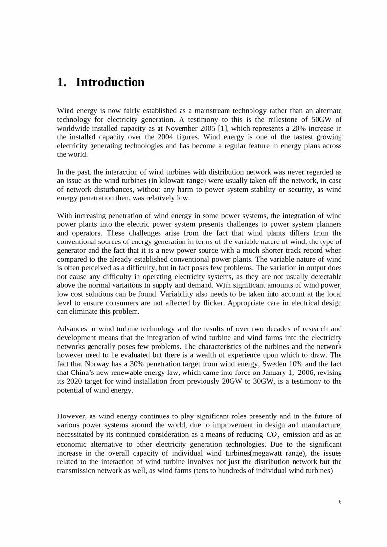
2. Wind Turbine Types Wind turbines are classified into two main classes which include: Fixed-speed wind turbine and the variable-speed wind turbine. Each turbines class is further classified based on the principle of operation of the gerenerator. Hence, the classification gives rise to the various types of wind turbine concept found today as given in Fig 1 and Table 1 and these include:[2]
Fig. 1.1 - Wind turbine concepts as used today in the wind industry

9
Table 1.1: Wind Turbine concepts
Power Control Speed Control
Stall Pitch Active Stall Fixed speed Type A Type A0 Type A1 Type A2
Type B Type B0 Type B1 Type B2
Type C Type C0 Type C1 Type C2
Variable speed
Type D Type D0 Type D1 Type D2
Note: The painted zones indicate combinations that are not in use in the wind turbine industry today. Notations: Fixed-Speed Wind Turbine - Type A Limited Variable-Speed Wind Turbine -Type B Variable-Speed Wind Turbine with Partial-Scale Frequency Converter -Type C Variable-Speed Wind Turbine with Full-Scale Frequency Converter -Type D Fixed-Speed Wind Turbine with Stall Control -Type A0 Fixed-Speed Wind Turbine with Pitch Control -Type A1 Fixed-Speed Wind Turbine with Active Stall Control -Type A2 Limited Variable-Speed Wind Turbine with Pitch Control - Type B1 Variable-Speed with Partial-Scale Frequency Converter with Pitch Control -Type C1 Variable-Speed with Full-Scale Frequency Converter with Pitch Control -Type D1
2.1. Fixed Speed Wind Turbine The early wind turbines operated at fixed speed. The rotor speed of this wind turbine is fixed irrespective of the wind speed. The rotor speed of this turbine is determined by the frequency of the supply grid, the gear ratio and the generator design. It is a characteristic of fixed-speed wind turbines to be equipped with an induction generator (squirrel cage or wound rotor) that is directly connected to the grid, with a soft-starter and a capacitor bank for reducing reactive power compensation. They are designed to achieve maximum efficiency at one particular wind speed. In order to increase power production, the generator of some fixed-speed wind turbines has two winding sets: one is used at low wind speeds (typically 8 poles) and the other at medium and high wind speeds (typically 4-6 poles).
10
The fixed-speed wind turbine has the following advantages:
• Simplicity • Reliability • Well proven • Low cost of electrical parts
However, its disadvantages include:
• Uncontrollable reactive power consumption • Mechanical stress • Limited power quality control
Owing to its fixed-speed operation, all fluctuations in the wind speed are further transmitted as fluctuations in the mechanical torque and then as fluctuations in the electrical power on the grid. In the case of weak grids, the power fluctuations can also lead to large voltage fluctuations, which, in turn, will result in significant line losses. 2.2. Fixed Speed Wind Turbine Controller This configuration denotes the fixed-speed wind turbine with an asynchronous squirrel cage induction generator (SCIG) directly connected to the grid via a transformer. Since the SCIG always draws reactive power from the grid, this configuration uses a capacitor bank for reactive power compensation. A smoother grid connection is achieved by using a soft-starter. Irrespective of the power control principle in a fixed-speed wind turbine, the wind fluctuations are converted into mechanical fluctuations and consequently into electrical power fluctuations. In the case of a weak grid, these can yield voltage fluctuations at the point of connection. Due to this voltage fluctuations, the fixed-speed wind turbine draws varying amounts of reactive power from the utility grid (unless there is a capacitor bank), which increases both the voltage fluctuations and the line losses. Thus the main drawbacks of this concept are that it does not support any speed control, it requires a stiff grid and its mechanical construction must be able to tolerate high mechanical stress.
11
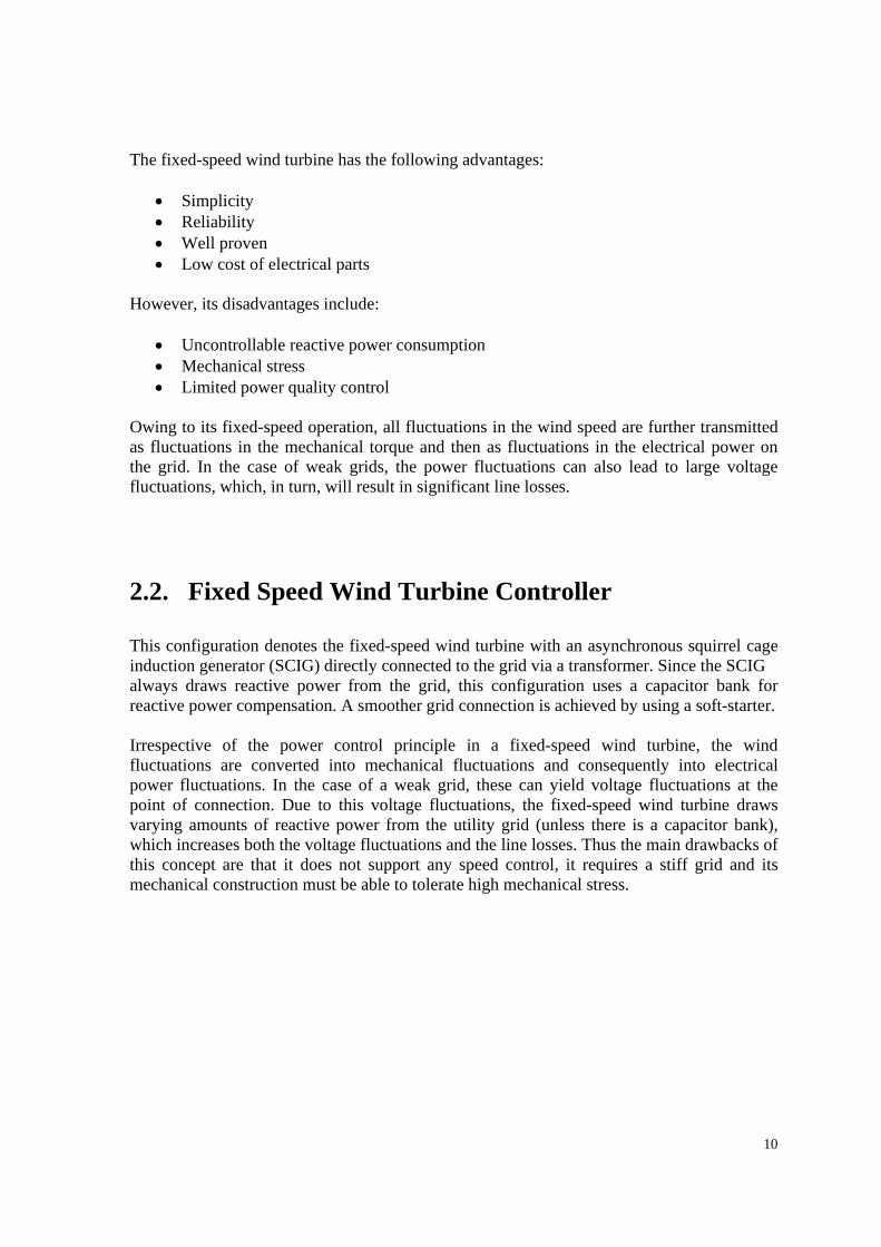
Fig 2.2 - Fixed Speed Wind Turbine Three classes or versions (Type A0, Type A1 and Type A2) of the fixed-speed wind turbine are used in the wind turbine industry and they can be characterised as follows: 2.2.1. Stall Controlled
This is the conventional concept applied by the Danish wind turbine manufacturer Vestas, in the 1980s and 1990s (i.e. an upwind stall-regulated three bladed wind turbine concept). It has been very popular because of its relatively low price, its simplicity and its robustness. Stall-controlled wind turbines cannot carry out assisted start-ups, which imply that the power of the turbine cannot be controlled during the connection sequence. 2.2.2. Pitch Controlled
These have also been present on the market. The main advantage of this type of turbine is that it enhances power controllability, controlled start-up and emergency stopping. Its major drawback is that, at high wind speeds, even small variations in wind speed result in large variations in output power. The pitch mechanism is not fast enough to avoid such power fluctuations. By pitching the blade, slow variations in the wind can be compensated, but this is not possible in the case of gusts.
12
2.2.3. Active Stall Controlled
These have recently become popular. This class of fixed-speed wind turbine basically maintains all the power quality characteristic of the stall-regulated system. The improvement lays in a better utilisation of the overall system, as a result the use of active stall control. The flexible coupling of the blades to the hub also facilitates emergency stopping and start-ups. One drawback is the higher price arising from the pitching mechanism and its controller. 2.3. Variable Speed Wind Turbine The variable-speed wind turbine has become a dominant player among the installed wind turbines in recent times. Variable-speed wind turbines achieve maximum aerodynamic efficiency over a wide range of wind speeds. With a variable-speed operation it has become possible to adapt (accelerate or decelerate) the rotational speed ω of the wind turbine to the wind speed V . This way the tip speed ratio λ is kept constant at a predefined value that corresponds to the maximum power coefficient. Contrary to a fixed-speed system, a variable-speed system keeps the generator torque fairly constant and the variations in wind are absorbed by changes in the generator speed. The electrical system of a variable-speed wind turbine is more complicated than that of a fixed-speed wind turbine. It is typically equipped with an induction or synchronous generator and connected to the grid through a power converter. The power converter controls the generator speed; that is, the power fluctuations caused by wind variations are absorbed mainly by changes in the rotor generator speed and consequently in the wind turbine rotor speed.
13
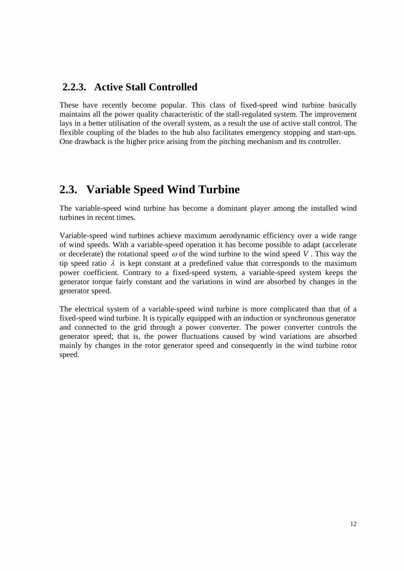
Gear box Grid
WRIG Soft-Starter
Capacitor Bank
Variable Resistance
Fig 2.3 - Variable Speed Wind Turbine The advantages of variable-speed wind turbines are an increased energy capture, improved power quality and reduced mechanical stress on the wind turbine. The disadvantages are losses in power electronics, the use of more components and the increased cost of equipment because of power electronics. The introduction of variable-speed wind turbine types increases the number of applicable generator types and also introduces several degrees of freedom in the combination of generator type and power converter type. 2.4. Variable Speed Wind Turbine Controller The variable speed concept is used by all three configurations, Type B, Type C and Type D. Owing to power limitation considerations, the variable speed concept is used in practice today only together with a fast-pitch mechanism. Variable speed stall or variable speed active stall-controlled wind turbines are not included in the write-up as potentially they lack the capability for a fast reduction of power. If the wind turbine is running at maximum speed and there is a strong gust, the aerodynamic torque can get critically high and may result in a runaway situation.
14
2.4.1. Limited Variable Speed
This configuration corresponds to the variable speed wind turbine with variable generator rotor resistance, known as OptiSlip. It uses a wound rotor induction generator (WRIG) and has been used by the Danish manufacturer Vestas since the mid-1990s. The generator is directly connected to the grid. A capacitor bank performs the reactive power compensation. A smoother grid connection is achieved by using a soft-starter. The unique feature of this concept is that it has a variable additional rotor resistance, which can be changed by optically controlled converter mounted on the rotor shaft. Thus, the total rotor resistance is controllable. This optical coupling eliminates the need for costly slip rings that need brushes and maintenance. The rotor resistance can be changed and thus controls the slip. This way, the power output in the system is controlled. The range of the dynamic speed control depends on the size of the variable rotor resistance. Typically the speed range is 0-10% above synchronous speed. The energy coming from external power conversion unit is dumped as heat loss Wallace and Oliver (1998) describe an alternative concept using passive components instead of a power electronic converter. This concept achieves a 10% slip, but it does not support a controllable slip. 2.4.2. Variable Speed with Partial Scale Frequency Converter
This configuration, known as the doubly fed induction generator (DFIG) concept corresponds to the limited variable speed wind turbine with a wound rotor induction generator (WRIG) and partial scale frequency converter (rated at approximately 30% of nominal generator power) on the rotor circuit. The partial scale frequency converter performs the reactive power compensation and the smoother grid connection. It has a wider range of dynamic speed control compared with the OptiSlip, depending on the size of the frequency converter.
15
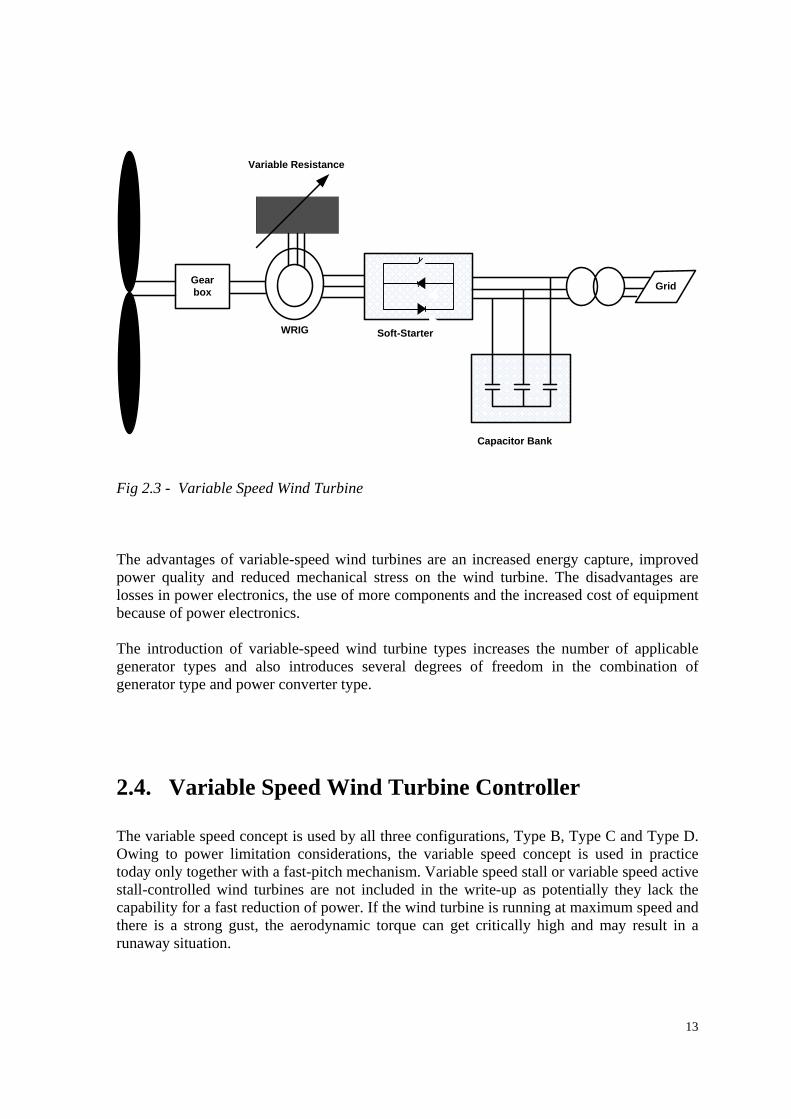
Turbine
Gear box
Grid
WRIG
Partial ScaleFrequency Converter
Fig 2.4.2 - Variable speed wind turbine with partial scale frequency converter Typically, the speed range comprises synchronous speed -40% to +30%. The smaller frequency converter makes this concept attractive from an economical point of view. Its main drawbacks are the use of slip rings and protection in the case of grid faults. 2.4.3. Variable Speed with Full Scale Frequency Converter
This configuration corresponds to full variable speed wind turbine, with the generator connected to the grid through a full-scale frequency converter. The frequency converter performs the reactive power compensation and the smoother grid connection. The generator can be excited electrically {wound rotor synchronous generator (WRSG) or WRIG) or by a permanent magnet {permanent magnet synchronous generator (PMSG)}.
16
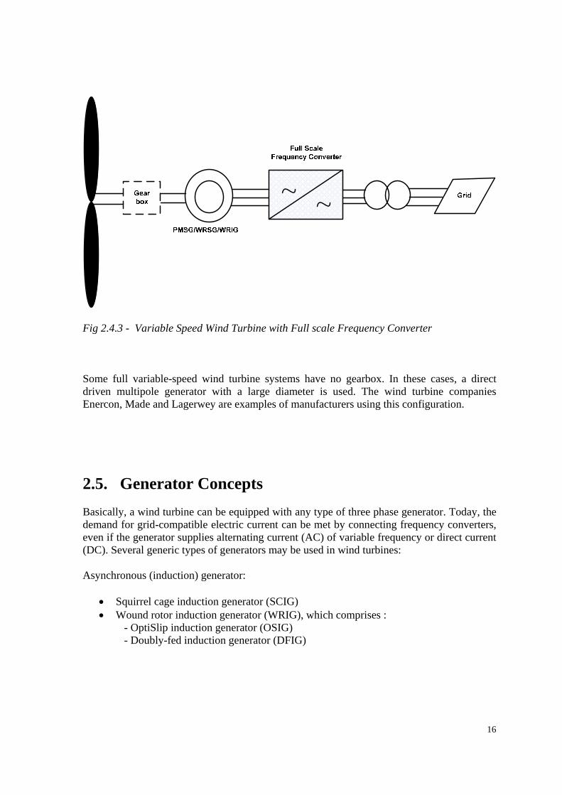
Fig 2.4.3 - Variable Speed Wind Turbine with Full scale Frequency Converter Some full variable-speed wind turbine systems have no gearbox. In these cases, a direct driven multipole generator with a large diameter is used. The wind turbine companies Enercon, Made and Lagerwey are examples of manufacturers using this configuration.
2.5. Generator Concepts Basically, a wind turbine can be equipped with any type of three phase generator. Today, the demand for grid-compatible electric current can be met by connecting frequency converters, even if the generator supplies alternating current (AC) of variable frequency or direct current (DC). Several generic types of generators may be used in wind turbines: Asynchronous (induction) generator:
• Squirrel cage induction generator (SCIG) • Wound rotor induction generator (WRIG), which comprises :
- OptiSlip induction generator (OSIG) - Doubly-fed induction generator (DFIG)
17
Synchronous generator:
• Wound rotor generator (WRSG) • Permanent magnet generator (PMSG)
Other types of generators include:
• High-voltage generator (HVG) • Switched reluctance generator (SRG) • Transverse flux generator (TFG)
2.5.1. Asynchronous (induction) Generator
This is the most common generator used in wind turbines. It has several advantages, such as robustness and mechanical simplicity. It is equally produced in large quantities at a lower price. Its major disadvantage it that the stator needs a reactive magnetising current. The asynchronous generator does not contain permanent magnets and is not separately excited. Therefore it has to receive its exciting current from another source and consumes reactive power. The reactive power may be supplied by the grid or by a power electronic system. The generator’s magnetic field is established only if it is connected to the grid. In the case of AC excitation, the created magnetic field rotates at a speed determined jointly by the number of poles in the winding and the frequency of the current, the synchronous speed. Thus, if the rotor rotates at a speed that exceeds the synchronous speed, an electric field is induced between the rotor and the rotating stator field by a relative motion (slip), which causes a current in the rotor windings. The interaction of the associated magnetic field of the rotor with the stator field results in the torque acting on the rotor. The rotor of an induction generator can be designed as a so called short-circuit rotor (squirrel cage rotor) or as a wound rotor. Squirrel Cage Induction Generator This generator has been the prevalent choice because of its mechanical simplicity, high efficiency and low maintenance requirements. This generator is used in constant speed wind turbines as the generator speed changes by only a few percent because of the generator slip caused by changes in the wind speed. The generator and the wind turbine rotor are coupled through a gearbox, as the optimal rotor and generator speed ranges are different. Wind turbines based on SCIG are typically equipped with a soft-starter mechanism and an installation for reactive power compensation, as SCIG consume reactive power. SCIGs have a steep torque speed characteristic and therefore fluctuations in wind power are transmitted
18
directly to the grid. These transients are especially critical during the grid connection of the wind turbine, where the in-rush current can be up to 7-8 times the rated current. In a weak grid, this high in-rush current can cause severe voltage disturbances. Therefore, the connection of the SCIG to the grid should be made gradually in order to limit the in-rush current. During normal operation and direct connection to a stiff AC grid, the SCIG is very robust and stable. The slip varies and increases with increasing load. The major problem it that, because of the magnetising current supplied from the grid to the stator winding, the full load power is relatively low. This has to be put in relation to the fact that most power distribution utilities penalise industrial customers that load with low power factors. Clearly, generation at a low power factor cannot be permitted here either. Too low a power factor is compensated by connecting capacitors in parallel to the generator. In SCIGs there is a unique relation between active power, reactive power, terminal voltage and rotor speed. This means that in high winds the wind turbine can produce more active power only if the generator draws more reactive power. For a SCIG, the amount of consumed reactive power is uncontrollable because it varies with wind conditions. Without any electrical components to supply the reactive power, the reactive power for the generator must be taken directly from the grid. Reactive power supplied by the grid causes additional transmission losses and in certain situations, can make the grid unstable. Capacitor banks or modern power electronic converters can be used to reduce the reactive power consumption. The main disadvantage is that the electrical transients occur during switching-in. In the case of a fault, SCIGs without any reactive power compensation system can lead to voltage instability on the grid. The wind turbine rotor may speed up (slip increases), for instance, when a fault occurs, owing to the imbalance between the electrical and mechanical torque. Thus, when the fault is cleared, SCIGs draw a large amount of reactive power from the grid, which leads to a further decease in voltage. SCIGs can be used both in fixed-speed wind turbines and in full variable-speed wind turbines. In the latter case, the variable frequency power of the machine is converted to fixed-frequency power by using a bidirectional full-load back-to-back converter. Wound Rotor Induction Generator In the case of a WRIG, the electrical characteristics of the rotor can be controlled from the outside and thereby a rotor voltage can be impressed. The windings of the wound rotor can be externally connected through slip rings and brushes or by means of power electronic equipment, which may or may not require slip rings and brushes. By using power electronics, the power can be extracted or impressed to the rotor circuit. It is also possible to recover slip energy from the rotor circuit and feed it into the output of the stator. The disadvantage of the WRIG is that it is more expensive and is not as robust as the SCIG. The wind turbine
19
industry uses most commonly the OptiSlip induction generator and the doubly-fed induction generator. OptiSlip Induction Generator This feature was introduced by Vestas in order to minimise the load on the wind turbine during gusts. The OptiSlip feature allows the generator to have a variable slip (narrow range) and to choose the optimum slip, resulting in smaller fluctuations in the drive train torque and in the power output. The variable slip is a very simple, reliable and cost-effective way to achieve load reductions compared with more complex solutions such as full variable-speed wind turbines using full-scale converters. OSIGs are WRIGs with a variable external rotor resistance attached to the rotor windings. The slip of the generator is changed by modifying the total rotor resistance by means of a converter, mounted on the rotor shaft. The converter is optically controlled, which means that no slip rings are necessary. The stator of the generator is connected directly to the grid. The advantages of this generator concept are a simple circuit topology, no need for slip rings and an improved operating speed range compared to SCIG. To a certain extent, this concept can reduce the mechanical loads and power fluctuations caused by gusts. However, it still requires a reactive power compensation system. The disadvantages are:
• the speed range is limited to 0-10%, as it is dependent on the size of the variable rotor resistance
• only poor control of active and reactive power is achieved • the slip power is dissipated in the variable resistance as losses.
Doubly-fed Induction Generator The concept of DFIG is an interesting option with a growing market. The DFIG consists of a WRIG with the stator windings directly connected to the constant-frequency three-phase grid and with the rotor windings mounted to a bidirectional back-to-back IGBT voltage source converter. The term “doubly-fed” refers to the fact that the voltage on the stator is applied from the grid and the voltage on the rotor is induced by the power converter. This system allows a variable-speed operation over a large, but restricted, range. The converter compensates the difference between the mechanical and electrical frequency by injecting a rotor current with a variable frequency. Both during normal operation and faults the behaviour of the generator is thus governed by the power converter and its controllers. The power converter consists of two converters, the rotor-side converter and the grid-side converter, which are controlled independently of each other. The main idea is that the rotor-
20
side converter controls the active and reactive power by controlling the rotor current components, while the line-side converter controls the DC-link voltage and ensures a converter operation at unity power factor (zero reactive power). Depending on the operating condition of the drive, power is fed into or out of the rotor; in an over synchronous situation, it flows from the rotor via the converter to the grid, whereas it flows in the opposite direction in a sub synchronous situation. In both cases – sub synchronous and over synchronous – the stator feeds energy into the grid. The DFIG has several advantages. It has the ability to control reactive power and to decouple active and reactive power control by independently controlling the rotor excitation current. The DFIG has not necessarily to be magnetised from the power grid, it can be magnetised from the rotor circuit, too. It is also capable of generating reactive power that can be delivered to the stator by the grid-side converter. However, the grid-side converter normally operates at unity power factor and is not involved in the reactive power exchange between the turbine and the grid. In case of a weak grid, where the voltage may fluctuate, the DFIG may be ordered to produce or absorb and amount of reactive power to or from the grid, with the purpose of voltage control. The size of the converter is not related to the total generator power but to the selected speed range and hence to the slip power. Thus the cost of the converter increases when the speed range around the synchronous speed becomes wider. The selection of the speed range is therefore based on the economic optimisation of investment costs and on increased efficiency. A drawback of the DFIG is the inevitable need for slip rings. 2.5.2. The Synchronous Generator
The synchronous generator is much more expensive and mechanically more complicated than and induction generator of a similar size. However, it has one clear advantage compared to the induction generator; it does not need a reactive magnetising current. The magnetic field in the synchronous generator can be created by permanent magnets or with a conventional field winding. If the synchronous generator has a suitable number of poles (a multipole WRSG or multipole PMSG), then it can be used for direct-drive applications without any gearbox. The synchronous machine is probably most suited for full power control as it is connected to the grid through a power electronic converter. The converter has two primary goals:
• to act as an energy buffer for the power fluctuations caused by an inherently gusting wind energy and for the transients coming from the net side
• to control the magnetisation and to avoid problems by remaining synchronous with the grid frequency.
21
Applying such a generator allows a variable-speed operation of wind turbines. Two classical types of synchronous generators have often been used in the wind turbine industry:
• The wound rotor synchronous generator (WRSG) • The permanent magnet synchronous generator
Wound Rotor Synchronous Generator The WRSG is the workhorse of the electrical power industry. Both the steady-state performance and the fault performance have been well-documented in a multitude of research papers over the years. The stator windings of WRSGs are connected directly to the grid and hence the rotational speed is strictly fixed by the frequency of the supply grid. The rotor winding is excited with direct current using slip rings and brushes or with a brushless exciter with a rotating rectifier. Unlike the induction generator, the synchronous generator does not need any further reactive power compensation system. The rotor winding, through which direct current flows, generates the exciter field, which rotates with synchronous speed. The speed of the synchronous generator is determined by the frequency of the rotating field and by the number of pole pairs of the rotor. The wind turbine manufacturer Enercon and Lagerwey use the wind turbine concept Type D with a multipole (low-speed) WRSG and no gearbox. It has the advantage that it does not need a gearbox. But the price that has to be paid for such a gearless design is a large and heavy generator and a full-scale power converter that has to handle the full power of the system. The wind turbine manufacturer Made also applies the wind turbine concept of Type D, but with a four-pole (high-speed) WRSG and a gearbox. Permanent Magnet Synchronous Generator Many research articles have suggested the application of PMSGs in wind turbines because of their property of self-excitation, which allows an operation at a high power factor and a high efficiency. In the permanent magnet machine, the efficiency is higher than in the induction machine, as the excitation is provided without any energy supply. However, the materials used for producing permanent magnets are expensive and they are difficult to work with during manufacturing. Additionally, the use of PM excitation requires the use of a full-scale power converter in order to adjust the voltage and frequency of generation to the voltage and frequency of transmission, respectively. This is an added expense. However, the benefit is that power can be generated at any speed so as to fit the current conditions. The stator of PMSGs is wound and the rotor is provided with a permanent magnet pole system and may
22
have salient poles or may be cylindrical. Salient poles are more common in slow-speed machines and may be cylindrical. Salient poles are more common in slow-speed machines and may be the most useful version for an application for wind generators. The synchronous nature of the PMSG may cause problems during start-up, synchronisation and voltage regulation. It does not readily provide constant voltage. The synchronous operation causes also a very stiff performance in the case of an external short circuit and if the wind speed is unsteady. Another disadvantage of PMSGs is that the magnetic materials are sensitive to temperature; for instance the magnet can lose its magnetic qualities at high temperature, during a fault, for example. Therefore, the rotor temperature of a PMSG must be supervised and a cooling system is required. Examples of wind turbine manufacturers that use configuration of Type D with PMSGs are Lagerwey, WinWind and Multibrid. 2.5.2. Other Generator Types
High Voltage Generator Most commonly, wind turbine generators are operated at 690V and they therefore require a transformer in the nacelle or at the bottom of the tower. The main motivation for increasing the voltage of the generator is to reduce the current and thereby reduce the losses and the amount of heat that has to be dissipated. This can lead to a reduction in the size of the generator and to a higher efficiency of the wind turbine, especially at higher loads. If the voltage of the machine matches the grid voltage, a grid connection is possible without a transformer. HVGs are manufactured both as a synchronous generator and as asynchronous generators. HVGs are potentially interesting alternative for large wind turbines exceeding 3MW. The major disadvantages are the high cost of the total system, the uncertainty regarding its long term performance and the safety requirements, which are more complex than those for low-voltage machines. The price could decrease in the future if the number of wind turbines with HVGs increases significantly. The Switched Reluctance Generator The SRG machine has a robust and simple mechanical structure, high efficiency, reduced costs and provides the opportunity to eliminate the gearbox. Literature on SRGs related to wind turbines is not substantial as much research remains to be done before it will be adapted to wind turbine application. However it is interesting for aerospace applications because of
23
its ability to continue operation at reduced output in the presence of faults in the generator itself. The SRG is a synchronous generator with a doubly salient construction, with salient poles on both the stator and the rotor. Excitation of the magnetic field is provided by the stator current in the same way as it is provided for the induction generator. The SRG is considered inferior to the PMSG machine because of its lower power density. The SRG requires a full-scale power converter in order to operate as a grid-connected generator. Moreover, the SRG has a lower efficiency than a PMSG and a lower power factor than asynchronous generators. Transverse Flux Generator The TFG machine topology is fairly new, but seems to be interesting. However, more research is required before the TFG machine will be adapted so that it can be used as a wind power generator. The transverse flux (TF) principle may be applied to a range of machine types. It could be used both in permanent magnet and in reluctance machines, for instance. The machine will inherently behave as the generic type that is applied, but will have characteristics that are influenced by the TF design. The high ratio of torque per kilogram of active material seems to be very attractive. The nature of its operation is equal to that of a synchronous machine and it will function in principle in a way that is similar to any other PM machine. It can comprise a very large number of poles, which may make it suitable for direct gearless applications. However, the TFG has a relatively large leakage inductance. In the reluctance version, this may cause the power factor to become very low during normal operation and the short-circuit current is insufficient to trip normal protection. A disadvantage of the TFG is the large number of individual parts that it requires and that a lamination technology has to be used. With the advance of powder technology this situation may improve.
24
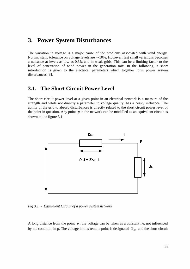
3. Power System Disturbances The variation in voltage is a major cause of the problems associated with wind energy. Normal static tolerance on voltage levels are +-10%. However, fast small variations becomes a nuisance at levels as low as 0.3% and in weak grids. This can be a limiting factor to the level of penetration of wind power in the generation mix. In the following, a short introduction is given to the electrical parameters which together form power system disturbances [3]. 3.1. The Short Circuit Power Level The short circuit power level at a given point in an electrical network is a measure of the strength and while not directly a parameter in voltage quality, has a heavy influence. The ability of the grid to absorb disturbances is directly related to the short circuit power level of the point in question. Any point p in the network can be modelled as an equivalent circuit as shown in the figure 3.1.
Fig 3.1. - Equivalent Circuit of a power system network A long distance from the point p , the voltage can be taken as a constant i.e. not influenced by the condition in p. The voltage in this remote point is designated SCU and the short circuit
25
power level SCS in MVA can be found as SC
SCZ
U 2where SCZ is the line impedance.
Variations in the load in p causes current variations in the line and these in turn a varying voltage drop in ( UΔ ) over the line impedance SCZ . The voltage in p ( LU ) is the difference between SCU and UΔ and this resulting voltage is seen by consumers connected to p and possibly disturbing them. Strong and/or weak grids are terms often used in connection with wind power installation. It is obvious from Fig 3.1. that if the impedance SCZ is small then the voltage variations in p will be small (the grid is strong) and consequently, if SCZ is large then the voltage variations will be large. Strong or weak are relative terms. For any given wind power installation of
installed capacity P(MW) the ratio SCR equals PSSC is a measure of the strength. The grid
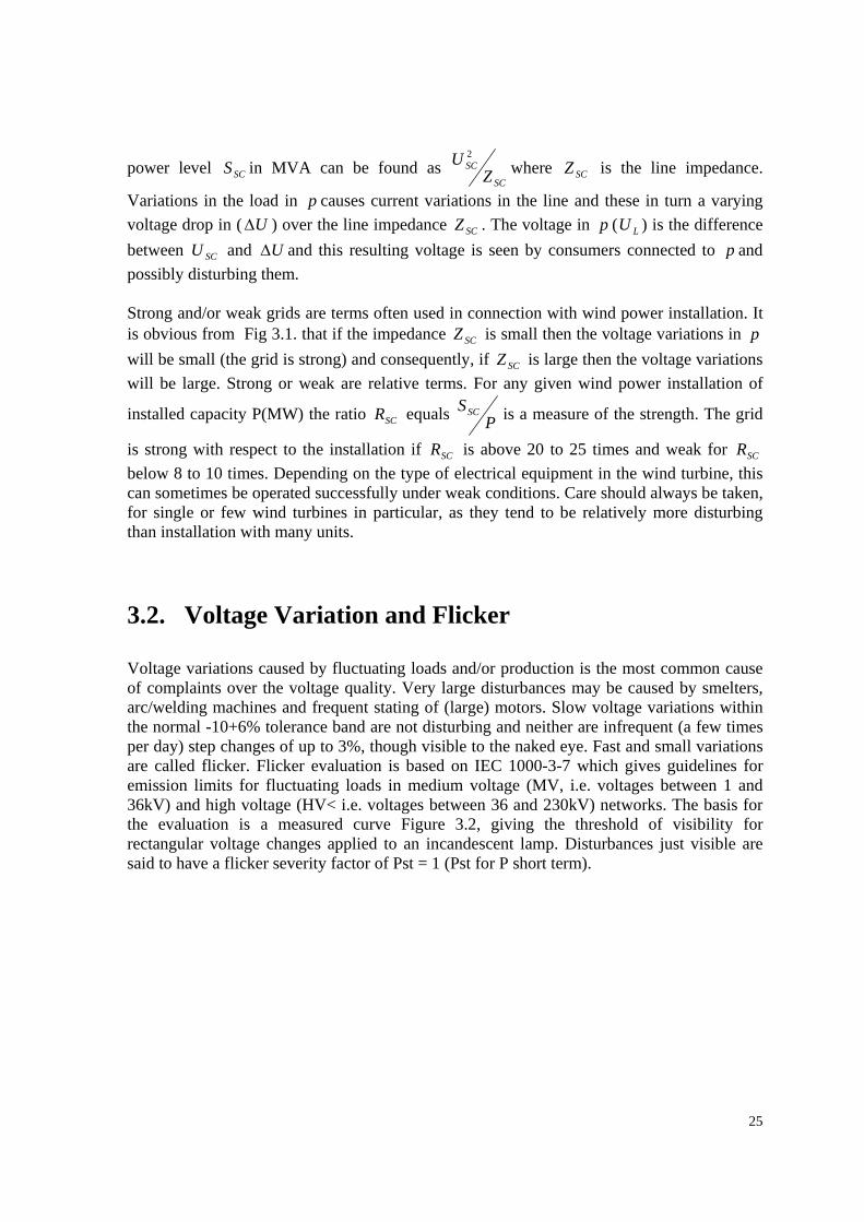
is strong with respect to the installation if SCR is above 20 to 25 times and weak for SCR below 8 to 10 times. Depending on the type of electrical equipment in the wind turbine, this can sometimes be operated successfully under weak conditions. Care should always be taken, for single or few wind turbines in particular, as they tend to be relatively more disturbing than installation with many units. 3.2. Voltage Variation and Flicker Voltage variations caused by fluctuating loads and/or production is the most common cause of complaints over the voltage quality. Very large disturbances may be caused by smelters, arc/welding machines and frequent stating of (large) motors. Slow voltage variations within the normal -10+6% tolerance band are not disturbing and neither are infrequent (a few times per day) step changes of up to 3%, though visible to the naked eye. Fast and small variations are called flicker. Flicker evaluation is based on IEC 1000-3-7 which gives guidelines for emission limits for fluctuating loads in medium voltage (MV, i.e. voltages between 1 and 36kV) and high voltage (HV< i.e. voltages between 36 and 230kV) networks. The basis for the evaluation is a measured curve Figure 3.2, giving the threshold of visibility for rectangular voltage changes applied to an incandescent lamp. Disturbances just visible are said to have a flicker severity factor of Pst = 1 (Pst for P short term).
26
Fig 3.2. - 1=stP curve for regular rectangular voltage changes Furthermore, a long term flicker severity factor ltP is defined as:
33
1
3,12
1 ∑=
=n
nstlt PP [4]
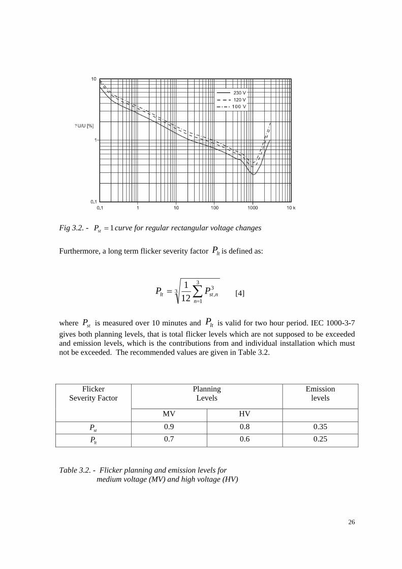
where stP is measured over 10 minutes and ltP is valid for two hour period. IEC 1000-3-7 gives both planning levels, that is total flicker levels which are not supposed to be exceeded and emission levels, which is the contributions from and individual installation which must not be exceeded. The recommended values are given in Table 3.2.
Planning Levels
Emission levels
Flicker Severity Factor
MV HV
stP 0.9 0.8 0.35
ltP 0.7 0.6 0.25
Table 3.2. - Flicker planning and emission levels for medium voltage (MV) and high voltage (HV)
27
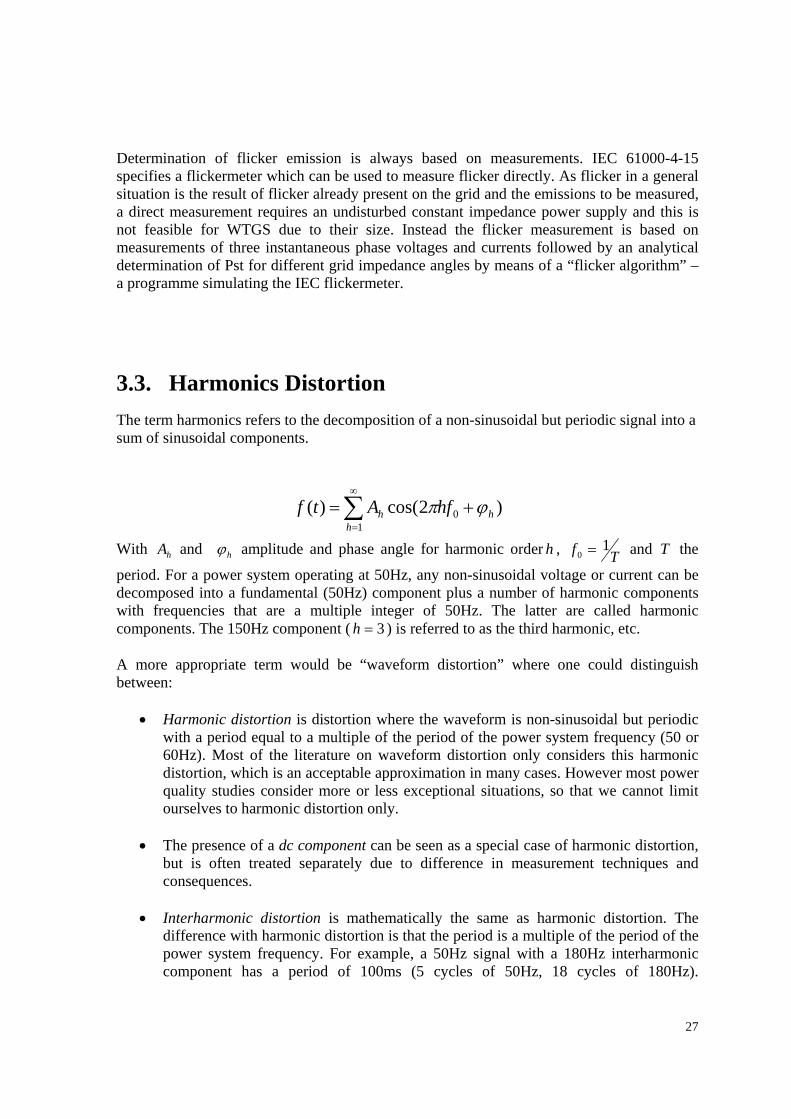
Determination of flicker emission is always based on measurements. IEC 61000-4-15 specifies a flickermeter which can be used to measure flicker directly. As flicker in a general situation is the result of flicker already present on the grid and the emissions to be measured, a direct measurement requires an undisturbed constant impedance power supply and this is not feasible for WTGS due to their size. Instead the flicker measurement is based on measurements of three instantaneous phase voltages and currents followed by an analytical determination of Pst for different grid impedance angles by means of a “flicker algorithm” – a programme simulating the IEC flickermeter. 3.3. Harmonics Distortion The term harmonics refers to the decomposition of a non-sinusoidal but periodic signal into a sum of sinusoidal components.
)2cos()(1
0 hh
h hfAtf ϕπ +=∑∞
=
With hA and hϕ amplitude and phase angle for harmonic order h , Tf 10 = and T the
period. For a power system operating at 50Hz, any non-sinusoidal voltage or current can be decomposed into a fundamental (50Hz) component plus a number of harmonic components with frequencies that are a multiple integer of 50Hz. The latter are called harmonic components. The 150Hz component ( 3=h ) is referred to as the third harmonic, etc. A more appropriate term would be “waveform distortion” where one could distinguish between:
• Harmonic distortion is distortion where the waveform is non-sinusoidal but periodic with a period equal to a multiple of the period of the power system frequency (50 or 60Hz). Most of the literature on waveform distortion only considers this harmonic distortion, which is an acceptable approximation in many cases. However most power quality studies consider more or less exceptional situations, so that we cannot limit ourselves to harmonic distortion only.
• The presence of a dc component can be seen as a special case of harmonic distortion,
but is often treated separately due to difference in measurement techniques and consequences.
• Interharmonic distortion is mathematically the same as harmonic distortion. The
difference with harmonic distortion is that the period is a multiple of the period of the power system frequency. For example, a 50Hz signal with a 180Hz interharmonic component has a period of 100ms (5 cycles of 50Hz, 18 cycles of 180Hz).
28
Mathematically, a frequency component at an irrational multiple of the power system frequency would lead to a non-periodic signal, but that case does not need to be considered in practice.
Harmonic distortion is due to the presence of non-linear elements in the power system (i.e. either in the network or in the loads). The main distortion is due to power electronic loads like computers, televisions, energy-saving lamps. Such loads can be found in increasing numbers with domestic and commercial customers leading to an increasing level of distortion in the network. Also adjustable-speed drives and arc furnaces are prominent for the distortion they cause. But these loads are mainly found with large industrial customers where mitigation methods are applied to limit the resulting voltage distortion. Therefore the resulting voltage distortion is mainly determined by small non-linear loads and not by large ones, although large non-linear loads sometimes cause local problems. The daily variation of the harmonic distortion clearly shows the pattern of domestic load, mainly televisions. Interharmonic distortion is much more related to industrial loads, and so is the noise component of waveform distortion. Capacitor banks are often incorrectly mentioned as a source of harmonic distortion. They are not a cause of harmonic distortion but their resonance with (mainly transformer) impedances leads to an amplification of the harmonic currents and voltages generated by non-linear loads. Consequences: Harmonic voltage distortion leads to harmonic currents through linear loads. These harmonic currents may cause extra losses in the loads which in turn require derating of the load. The effect is especially severe for lower-order voltage harmonics at the terminals of rotating machines. Rotating machines are designed for a given maximum amount of voltage unbalance. The presence of voltage distortion limits the immunity of the machine for voltage unbalance. Some sensitive electronic loads are negatively affected by high harmonic voltage distortion. The effect on such loads is however not so much related to harmonic spectrum but to the actual waveform, e.g. notching and multiple zero-crossings. An indirect effect of harmonic voltage distortion is that the efficiency of rectifiers become less when the crest factor (the maximum of the voltage waveform) decreases. Loads also become more sensitive to voltage dips. A high crest factor (harmonic over voltage) on the other hand may cause faster ageing of the insulation. The main effect of harmonic current distortion is overheating of series components like transformers and cables. The heating is proportional to the r.m.s. current; whereas, the transported energy is related to the fundamental component. For a given active power, the heating increases with increasing current distortion. The effect, however, is more severe than would follow from this reasoning as the resistance of transformers increases with frequency. The higher order harmonics thus produce more heating per Ampere than the fundamental
29
component. Heavy distorted current waveforms require a de-rating of transformers. The effect is also present for cables and lines, but to a minor extent. Mitigation: This is seen as a means of reducing the harmonic voltage or current distortion. However the problem can also be mitigated by improving the immunity of equipment. De-rating of transformers and motors is a way of mitigating the harmonic problem, albeit not necessarily the most economic solution. A more common way of tackling the harmonic problem is by installing filters, typically LC-series connections that shunt the unwanted harmonic current components back to the load. The harmonic currents remain high but they do not spread through the system and do not cause much harmonic voltage distortion. The disadvantages of the so-called passive filters (high risk of overload, introduction of new resonances) has led to the development of so-called active filters where the current is fully controlled and adjusted to the existing voltage or current distortion. Other mitigation methods include improvements in the network (de-rating of transformers, splitting sensitive and polluting loads) and improvements in the load. The latter includes a more sinusoidal current waveform (reduced emission) but also an increased immunity to voltage distortion. Reduced emission is seen by many as the preferred long term solution of the harmonic distortion problem. An important component in addressing harmonic problem is in defining limits to harmonic voltage and current distortion. The limits on harmonic voltage distortion as mentioned in various national and international standards are mainly a formalisation of the already existing distortion. For harmonic current limits, IEC and IEEE use two principally different approaches. The IEC standards set limits to the amount of emission of individual equipment, whereas the IEEE harmonic standard limits the emission per customer. Under the IEEE standard the responsibility lies with the customer who may decide to install filters instead of buying better equipment. Under the IEC standards the responsibility lies with the manufacturers of polluting equipment. The difference can be traced back to the aim of the documents: the IEEE standard aimed at regulating the connection of large industrial customers, whereas the IEC document mainly aims at small customers that do not have the means to choose between mitigation options. 3.4. Switching Operation and Soft Starting Connection and – to a smaller degree – disconnection of electrical equipment in general and induction generators/motors especially, gives rise to so called transients, that is short duration very high inrush currents causing both disturbances to the grid and high torque spikes in the drive train of a WT with a directly connected generator.
30
In this context WT fall into two classes: One featuring power electronics with rated capacity corresponding to the generator size in the main circuit. The other class has zero or low rating power electronics in a secondary circuit (typically the rotor circuit of an induction generator). The power electronics in the first class can control the inrush current continuously from zero to rated current. Its disturbances to the grid during switching operations are minimal and it will not be discussed further here. Unless special precautions are taken, the other class will allow inrush currents up to 5-7 times the rated current of the generator after the first very short period (below 100ms) where the peak is considerably higher, up to 18 times the normal rated current. A transient like this disturbs the grid and to limit it to an acceptable value all WT of this class are equipped with a current limiter or soft starter based on thyristor technology which typically limits the higher RMS value of the inrush current of the generator. The soft starter has a limited thermal capacity and is short circuited by a contactor able to carry the full load current when connection to the grid has been completed. In addition to reducing the impact on the grid, the soft starter also effectively damps the torque peaks in the air gap of the generator associated with the peak currents and hence reduces the load on the gearbox.
31
4. Low Voltage Ride-through Capability of Wind Turbines In the past, most utilities requested that wind farms trip or drop out in the event of faults in the grid. Both local and remote faults produce voltage dips which cause wind turbines (normally programmed to drop out at 70% voltage) to trip. Today, however, the concept of low voltage ride-through capability for wind turbines arose because wind energy now constitute a growing source of energy generation and as a such having an increasing level of penetration in many power systems around the world. This results in having the traditional idea of dropout of wind farms during system faults given way to many utilities requesting that wind turbines and wind farms ride through grid disturbances, remain on-line and continue to support the system. Most wind turbine manufacturers now have products that support ride-through capability for voltage dips on the power system for a stipulated duration of time. This has been achieved largely as a result of upgrade in order to meet the specification of many utilities by the manufacturers. Notable among the manufacturers include General Electric (GE) which in 2003 introduced its 1.5 MW wind turbines equipped with low voltage ride through capability. Enercon GmbH, the German wind turbine manufacturer, Vestas Wind Systems A/S, the Danish manufacturer and many other wind turbine manufacturers, have products today that meet varying degrees of requirement regarding low voltage ride through capability. The addition of low voltage ride-through capability for wind turbines is part of the continuing advancement of technology related to wind turbines that has made wind power an increasingly competitive source of energy in today’s environment. Wind turbines of today are larger and more reliable than ever before and have the capability of operating in a broad range of conditions at various locations. The ride-through capability of a wind turbine as earlier mentioned refers to the ability of the wind power generator to remain in service in the presence of a fault on the power system. The turbine on its own does not provide this capability, but the electronic devices built into the wind power plant enable the turbine to be able to remain in service in the presence of faults.
32
4.1. Power Electronic Concepts The variable-speed wind turbine concept requires a power electronic system that is capable of adjusting the generator frequency and voltage to the grid. Before presenting the current status regarding power electronics, it is important to understand why it is attractive to use power electronics in future wind turbines. Controllable frequency: Power electronics make it possible to apply the variable-speed concept and it is therefore important from a wind turbine point of view. This feature results in the following direct benefits to wind turbines:
• Optimal energy operation • Reduced loads on the gear and drive train • Load control • Gearless option • Reduced noise
The disadvantages with regard to wind turbine in using power electronics are:
• Additional costs • Power losses
Power plant characteristics: Power electronics provide the possibility for wind farms to become active elements in the power system. With regard to the grid, the advantages include:
• Controllable active and reactive power • Local reactive power source • Improved network (voltage) stability • Improved power quality
With regard to the grid, power electronics have the disadvantage of generating high harmonic currents on the grid. Power electronics is a rapidly developing technology. Components can handle higher current and voltage ratings, the power losses decrease and the devices become more reliable. The devices are also very easy to control with a megascale power amplification. The price/power ratio is still decreasing and power converters are becoming more and more attractive as a means of improving the performance of wind turbines. In this section we will present the power converter topologies that are most commonly used in wind turbine applications, including their advantages and disadvantages. 4.1.1. Soft-starter
The soft-starter is a simple and cheap power electronic component used in fixed-speed wind turbines during their connection to the grid. The soft-starter’s function is to reduce the in-
33
rush current, and thereby limiting the disturbances to the grid. Without a soft-starter, the in-rush current can be up to 7-8 times the rated current, which can cause severe voltage disturbances on the grid. The soft-starter contains two thyristors as commutation devices in each phase. They are connected antiparallel for each phase. The smooth connection of the generator to the grid, during a predefined number of grid periods, is achieved by adjusting the firing angle (α ) of the thyristor. The relationship between the firing angle and the resulting amplification of the soft-starter is highly nonlinear and is additionally a function of the power factor of the connected element. After the in-rush, the thyristors are bypassed in order to reduce the losses of the overall system. 4.1.2. Rectifiers and Inverters
A traditional frequency converter, also called an adjustable speed drive, consists of:
• A rectifier to convert alternating current into direct current, while the energy flows into the DC system
• Energy storage (capacitors) • An inverter (DC-to-AC with controllable frequency and voltage) to convert direct
current into alternating current, while the energy flows to the AC side. Diodes can be used only in rectification mode, whereas electronic switches can be used in rectifying as well as in inverting mode. The most common rectifier solution is the diode rectifier, because of its simplicity, its low cost and low losses. It is nonlinear in nature and consequently, it generates harmonic currents. Another drawback is that it allows only a unidirectional power flow; it cannot control the generator voltage or current. Therefore, it can be used only with a generator that can control the voltage and with an inverter (e.g. an IGBT) that can control the current. The thyristor (grid-commutated) based inverter solution is a cheap inverter, with low losses and as its name indicates, it needs to be connected to the grid to be able to operate. Unfortunately, it consumes reactive power and produces large harmonics. The increasing demands on power quality make thyristor inverters less attractive to self-commutated inverters, such as GTO inverters and IGBTs. The advantage of a GTO inverter is that it can handle more power than the IGBT, but this feature will be less important in the future, because of the fast development of IGBTs. The disadvantage of GTOs is that the control circuit of the GTO valve is more complicated. The generator and the rectifier must be selected as a combination (i.e. a complete solution), while the inverter can be selected almost independently of the generator and the rectifier. A diode rectifier or a thyristor rectifier can be used together only with a synchronous generator,
34
as it does not require a reactive magnetising current. As opposed to this, GTO and IGBT rectifiers have to be used together with variable-speed induction generators, because they are able to control the reactive power. However, even though IGBTs are a very attractive choice, they have the disadvantage of a high price and high losses.
4.2. Power Electronic Solutions in Wind Farms Today and in the future, wind turbines will be sited in large concentrations with hundreds of megawatts of power capacity. Wind farms of this size will often be connected directly to the transmission grid and will, sooner or later, replace conventional power plants. This means that the wind turbines will be required to have power plant characteristics, namely to be able to behave as active controllable components in the power system. Such large wind farms will be expected to meet very high technical demands, such as to perform frequency and voltage control, to regulate active and reactive power and to provide quick responses during transient and dynamic situations in the power system. The traditional wind turbines, where the active power is controlled by a simple pitching of the blades or by using a dumping device or by disconnecting the wind turbines, do not have such control capabilities and cannot contribute to power system stability as will be required. Storage technologies may be an option, but at present such technologies are rather expensive. Also, they are not a satisfactory solution in the case of large wind farms, because of voltage stability issues. Power electronic technology will therefore become more and more attractive for large wind farms that will have to fulfil future high demands. There is significant research activities needed to develop the electrical control layout of such wind farms with different types of power electronic converters in order to be able to comply with the high requirements and to be as cheap as possible to install. Many control topologies are being investigated and some are already being implemented in practice. Depending on how the power electronic devices are used inside a wind farm, there are several different topology options, each with its particular advantages and disadvantages. The topology can include the following:
• A completely decentralised control structure with an internal AC network connected to the main grid, with each turbine in the wind farm having its own frequency converter and its own control system, has the advantage that each wind turbine can operate at its optimum level with respect to its local wind condition.
• A partly centralised, partly decentralised control structure where the power converter is ‘split up’ and the output of each turbine is locally rectified and fed into a DC network, with the whole farm still connected through a central inverter. However this solution is yet to be implemented in practice. The configuration provides all the features of the variable-speed concept, since each wind turbine can be controlled independently.
• A completely centralised control structure has a central power electronic converter connected to the wind farm’s connection point. The turbines either could have
35
squirrel-cage induction generators or wound-rotor synchronous generators. The advantage of such structure is that the internal behaviour of the wind turbine is separated from the grid behaviour and thus the wind farm is robust to possible failures of the grid. The disadvantage of this concept is that all wind turbines are rotating with the same average angular speed and not at an individual optimal speed, thereby giving up some of the variable-speed concept, for each individual wind turbine. An option of this concept is the centralised reactive power compensation topology with an advanced static VAR compensation (ASVC) unit. Reactive power compensation units are widely used in power systems in order to provide the reactive power balance and to improve voltage stability. ASVCs are inverters based on self-commutated switches (i.e. with full, continuous control of reactive power). They have the advantage that, in the case of a voltage decrease (e.g. during a grid fault) their available maximum reactive power decreases more slowly compared with the static VAR compensation (SVC) units.
The application of power electronic technology in large wind farms seems thus to be very promising. It plays a key role in complying with the high requirements that utility companies impose on wind farms. This technology therefore needs substantial additional research and development.
36
5. Interaction of Wind Power Plants with Electricity Network
The technical standards that are adopted by the power system industry often originate from standards developed by the Institute of Electrical and Electronic Engineer (IEEE) or from the International Electrotechnical Commission (IEC). However, these standards are voluntary, unless a specific organisation or legislative ruling requires the adoption of these standards. Hence, there are a large number of additional national or regional standards, requirements, guidelines recommendation or instructions for the interconnection for wind turbines or wind farms globally. In the 1980’s, distribution companies in Europe developed their own interconnection rules or standards. Initially each network company, facing increasing interconnection request from wind power plants, developed their own rules. During the 1990’s, these interconnection rules where harmonised on a national level. This harmonisation process often involved national network associations as well as national wind energy associations, which represent the interest of wind plant developers and owners. National interconnection rules are reformulated as a result of increasing wind power penetration and the rapid development of wind turbine technology (i.e. wind turbine ratings increased rapidly, from around 200kW in early 1990’s to 3-4 MW turbines in early 2004). In addition wind technology introduced new technologies such as doubly-fed induction generators (DFIGs). Until then, generation technologies that used DFIGs with a rating of up to 3MW and combined a large number of these within one power station (i.e. wind farms) were unheard of in the power industry. Not only was the increased size of the wind turbines new, but also the increasing size of the wind farms, which resulted in interconnection requests at the transmission level. Hence, interconnection rules for wind farms to be connected to the transmission level were required. Unfortunately, the continuously changing network rules and the re-regulation of the power market make a comparison or evaluation of the already very complex interconnection rules very difficult and there is only very limited literature in the area. A comparison of the various national interconnection rules that exists shows that:
• Interconnection rules are often a source of controversies between wind farm developers and network operators.
• It would provide a better understanding of the relevant issues for those countries, regions or utilities that are still in the process of developing interconnection rules for wind farms. This would help to harmonise interconnection rules globally.
• To comply with new connection requirements is a challenge for wind turbine manufacturers. New hardware and control strategies have to be developed. The
37
comparison of connection requirements in different countries will give wind turbine manufacturers an overview of the existing rules.
• An understanding of the difference between the national rules will contribute to a harmonisation of interconnection rules in Europe and even beyond.
5.1. Regulations for Networks below 100kV The guidelines, recommendations and requirements relevant to distribution networks [low-voltage (LV) and medium voltage (MV) level] are directed towards distribution network companies, wind turbine manufacturers and network operators as well as others who are interested in connecting wind farms to LV and MV network. This is to ensure that wind turbines are connected to distribution networks in compliance with applicable standards for voltage quality and reliability of supply. The guidelines and requirements should be independent of the design approach used for the wind turbine and open enough to apply to synchronous or induction generators with or without inverters, for instance. They deal with the technical data needed to assess the impact of wind turbines on power quality and discuss the requirements to be met by networks to which wind turbines are to be connected. (voltage quality at the customer side) Power system operators in many countries are required to prepare technical regulations for the connection of power generating plants to the public power supply grid and regulations concerning the player’s obligation. The regulations must enable the system operators to maintain technical quality and balance within the interconnected power system etc [5- Ekraft and Eltra – Technical regulations for the properties and control of wind turbines connected to grids with voltages below 100KV –may, 2004]. Previously, control and stabilisation in the electricity system was taken care of only by large power station units. However, with deregulation and the emergence of small-scale production plants, all generating plants, including wind power plants, must take part in those tasks in the future. The technical regulation concerning wind plants connected to the distribution network is intended to ensure among other things, that wind turbines have the control and dynamic properties needed for the operation of the power system with respect to both short-term and long-term security of supply and voltage quality. 5.1.1. Frequency Control
The frequency that exists at any instant in a power system is an indication of the level of balance between production and demand of electricity. In normal operation of a power system, this relation holds:
38
Loadgen PP = (At all times) Since it is impossible to store electrical energy in large quantities, it means that all attempts must be geared towards maintaining the above relation. Thus the frequency should be close to its nominal value, say 50± 0.1Hz for a 50Hz system and rarely go outside the range of 49-50.3 Hz. The principle of frequency control is to keep the frequency constant at any instant. An increase in load demand, leads to a decrease in frequency. In a power system, the frequency-sensitive equipment (primary control units) will increase their generation until there is a balance between generation and consumption which ultimately leads to the restoration of the nominal frequency. The time span for this is 1-30 s. In order to restore the frequency to its nominal value and release used primary reserves, the secondary control is employed with a time span of 10-15 min. The secondary control thus results in a slower increase or decrease of generation. In some countries, automatic generation control is used; in other countries, such as in Sweden, the secondary control is accomplished by request from the system operator. At normal operation, the power output of a wind farm can vary up to 15% of the installed capacity within 15 minutes. This could lead to additional imbalances between production and consumption in the system. Considerably larger variations of power production and consumption may occur during and after extreme wind conditions. As wind turbines use other generation technologies than conventional power plants, they have limited capability of participating in primary frequency control in the same way as conventional generators do. The Irish electricity board, for instance, requires wind farms to include primary frequency control capabilities of 3-5% (as required for thermal power plants) into the control of the wind farm power output. Other regulators also require wind farms to be able to participate in the secondary frequency control. During overfrequencies, this can be achieved by shutting down of some turbines in the wind farm or by pitch control. Since wind cannot be controlled, power production at normal frequency would be intentionally kept lower, in order to be able to provide secondary control at underfrequencies[6]. 5.1.2. Voltage Control
Voltage control refers to the task of keeping the node voltages in the system within the required limits and of preventing any deviation from the nominal value to become larger than allowed. Utility and customer equipment is designed to operate at a certain voltage rating. Voltage regulators and the control of reactive power at the generators and consumption connection points are used in order to keep the voltage within the required limits and avoid voltage stability problems. Wind turbines also have to contribute to voltage regulation in the system; the requirement either refers to a certain voltage range that has to be maintained at
39
the point of connection of a wind turbine or wind farm, or to a certain reactive power compensation that has to be provided. Voltage control is necessary because transformers, lines and cables have the capacitance, resistance and inductance. Since cables and lines have susceptance and impedance, a current flowing through a network causes voltage differences between the ends of the lines (i.e. between nodes). However, even though there is a voltage difference between the two ends of the line, the node voltage is not allowed to deviate from the nominal value of the voltage in excess of a certain value (normally 5% to 10%). Appropriate measures must be taken to prevent such deviation. It should be noted that if cables and lines where not to have susceptance and impedance, the voltage anywhere in the system would be equal to that at the generators and voltage control would not be necessary. It is also important to stress that node voltage is a local quantity, as opposed to system frequency, which is a global or system-wide quantity. It is therefore not possible to control the voltage of a certain node from any point in the system, as is the case with frequency (provided that no network overloads are caused by associated power flows). Instead, the voltage of a certain node can only be controlled from that particular node or in its direct vicinity. To really appreciate what impact the replacement of conventional generation by wind power has on voltage control, it is very important to keep this specific property of the voltage control problem in mind. There are various ways to affect node voltages. They differ fundamentally between transmission networks and distribution grids. This is because of the different characteristics of lines in transmission networks and distribution grids and the divergent numbers and characteristics of the generators connected to both. Distribution networks consists of overhead lines or underground cables whose high resistance compared with its inductance is significant (i.e. distribution networks has high R/X ratios). On the other hand, transmission networks consists of overhead lines with low resistance (i.e. transmission networks has low R/X ratios) and the node voltages are controlled by changing the reactive power generation and consumption of large scale centralised generators connected to the transmission network. Therefore the impact of reactive power on node voltages on distribution networks are less pronounced than in the case of transmission networks. Further, the generators connected to distribution grids are not always capable of varying their reactive power output for contributing to voltage control. Node voltages in distribution grids are therefore controlled mainly by changing the turns ratio of the transformer that connects the distribution grid to the higher voltage level and sometimes also by devices that generate or consume reactive power, such as shunt reactors and capacitors. In general, distribution grids offer far fewer possibilities for node voltage control than transmission networks.
40
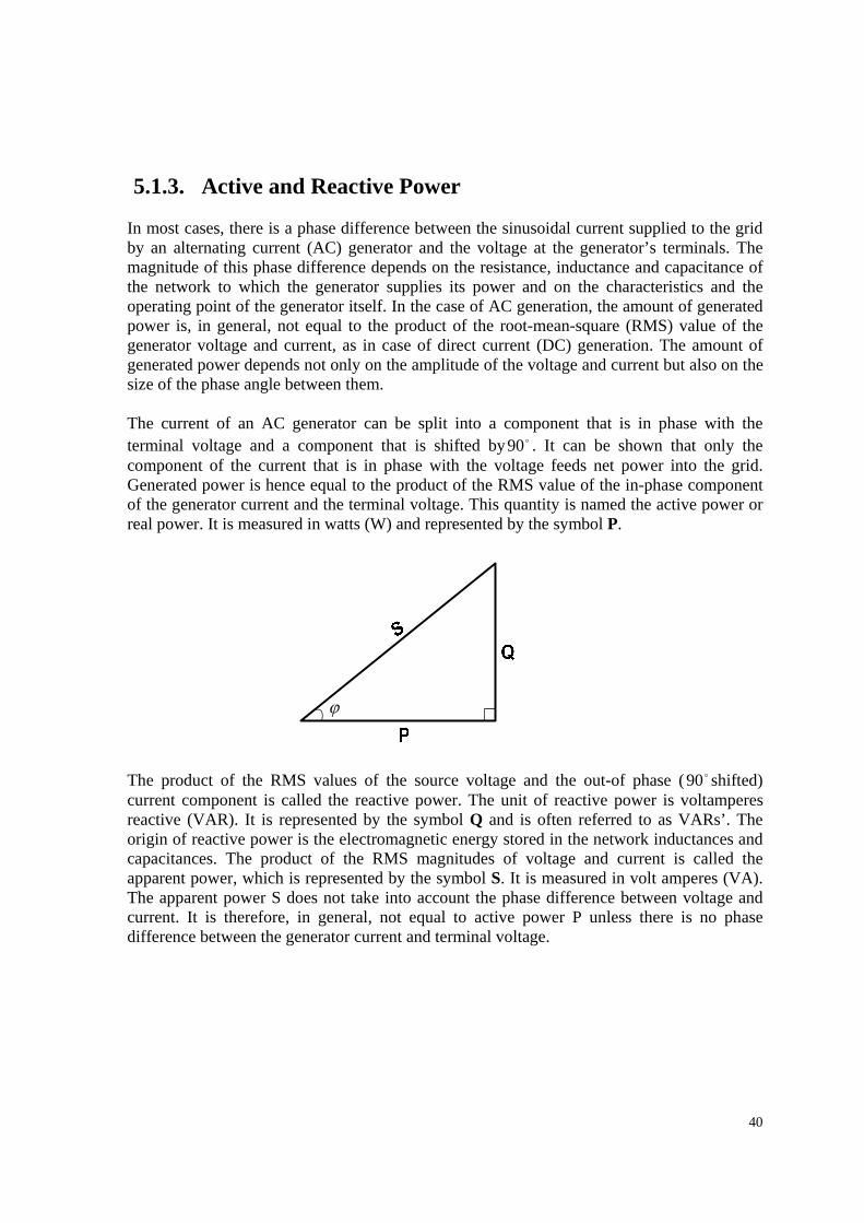
5.1.3. Active and Reactive Power
In most cases, there is a phase difference between the sinusoidal current supplied to the grid by an alternating current (AC) generator and the voltage at the generator’s terminals. The magnitude of this phase difference depends on the resistance, inductance and capacitance of the network to which the generator supplies its power and on the characteristics and the operating point of the generator itself. In the case of AC generation, the amount of generated power is, in general, not equal to the product of the root-mean-square (RMS) value of the generator voltage and current, as in case of direct current (DC) generation. The amount of generated power depends not only on the amplitude of the voltage and current but also on the size of the phase angle between them. The current of an AC generator can be split into a component that is in phase with the terminal voltage and a component that is shifted by o90 . It can be shown that only the component of the current that is in phase with the voltage feeds net power into the grid. Generated power is hence equal to the product of the RMS value of the in-phase component of the generator current and the terminal voltage. This quantity is named the active power or real power. It is measured in watts (W) and represented by the symbol P. The product of the RMS values of the source voltage and the out-of phase ( o90 shifted) current component is called the reactive power. The unit of reactive power is voltamperes reactive (VAR). It is represented by the symbol Q and is often referred to as VARs’. The origin of reactive power is the electromagnetic energy stored in the network inductances and capacitances. The product of the RMS magnitudes of voltage and current is called the apparent power, which is represented by the symbol S. It is measured in volt amperes (VA). The apparent power S does not take into account the phase difference between voltage and current. It is therefore, in general, not equal to active power P unless there is no phase difference between the generator current and terminal voltage.
ϕ
41
Another important quantity is the power factor (PF). The PF is defined as follows:
PF = cosϕ = SP =
22 QPP+
Where ϕ is the phase angle between the terminal voltage and terminal current, in degrees or radians. If ϕ equals 0, its cosine equals 1, reactive power Q equals 0 and apparent power S equals real power P. In that case, only active power is exchanged with the grid and there is no reactive power. This mode of operation is referred to as ‘cosϕ equal to one’ or as ‘unity power factor’. 5.1.4. Active Power Control
Generally, power production and consumption have to be in balance within a power system. Changes in power supply or demand can lead to a temporary imbalance in the system and affect operating conditions of power plants as well as affecting consumers. In order to avoid long-term unbalanced conditions the power demand is predicted and power plants adjust their power production. The requirements regarding active power control of wind farms aim to ensure a stable frequency in the system, to prevent overloading of transmission lines, to ensure compliances with power quality standards and to avoid large steps and in-rush currents during startup and shutdown of wind turbines. The active power control requirement of the transmission system operators Eltra and Elkraft of Denmark is given in table 5.1
Requirement Source Active Power: 1 min average = ± 5% of rated power of the wind turbine from conditional set point (0-100% of maximum power of wind farm)
Eltra and Elkraft [7]
Active Power Change: Specific reduction must be possible; reduction order comes from system operator
Eltra and Elkraft

42
5.2. Impact of Wind Power on Voltage Control in
Distribution Networks There should always be a distinction on the impact of wind power on voltage control in distribution and transmission networks. The task of voltage control in transmission networks was traditionally handled by large scale power plants using synchronous generators. Some dedicated equipment such as capacitor banks were used as well. These traditional, vertically integrated, utilities have operated power generating units, on one hand, and power transmission and distribution systems, on the other hand. They also have handled the voltage control issue, both short-term (day-to-day dispatch of units) and long-term (system planning). Owing to recent developments, this is, however, changing. First, the liberalisation and restructuring of the electricity sector that is currently being implemented in many countries has resulted in the unbundling of power generation and grid operation. These activities are no longer combined in vertically integrated utilities as they used to be. As a consequence, voltage control is no longer a ‘natural part’ of the planning and dispatch of power plants. Now independent generation companies carry out the planning and dispatch and in the long term, conventional power stations that are considered unprofitable will be closed down without considering their importance for grid voltage control. In addition, grid companies today often have to solve any voltage control problem that may result from decisions taken by generation companies, either themselves or supported by the generation company. In the short term, additional equipment for controlling the voltage can be installed. Another recent development is that generation is shifted from the transmission network to the distribution grid. Traditionally, the two most important approaches towards voltage control in distribution grids are the use of tap-changing transformers (i.e. transformers in which the turns ratio can be changed) and devices that can generate or consume reactive power (i.e. shunt capacitors or reactors). Use of tap-changing transformers is a rather cumbersome way of controlling node voltages. Rather than affecting the voltage at one node and in its direct vicinity, the whole voltage profile of the distribution grid is shifted up or down, depending on whether the transformer turns ratio is decreased or increased. Capacitors and reactors perform better in this respect, because they affect mainly the voltage of the node to which they are connected. However, the sensitivity of the node voltage to changes in reactive power is rather limited and therefore relatively large capacitors and reactors are necessary. This disadvantage is due to high R/X ratio of the branches in distribution grids when compared with that in transmission networks. As was the case for transmission networks, recent developments are complicating the task of maintaining node voltages throughout distribution grids. More and more distributed generation (also referred to as embedded, decentralised or dispersed generation), such as wind turbines, solar photovoltaic (PV) systems and small combined heat and power (CHP) generation is being connected to distribution grids. These generators affect the power flows in distribution grids. In particular, if their output power does not correlate with the load, as is
43
the case with generators using and uncontrollable prime mover, such as wind or sunlight, the variations in the current through the branches and therefore in the node voltages increase. The maximum and minimum value of the current through a certain branch used to depend on the load only, but, with the connection of distributed generation, the current limits have become dependent on the load as well as on the output of the distributed generator. The limits are now determined by a situation with minimum generation and maximum load, on one hand and maximum generation and minimum load on the other, rather than only by the difference between minimum and maximum load, as used to be the case. One might argue that with an increasing number of generators connected to the distribution grid, the voltage control possibilities might increase as well. However, in many cases these small-scale generators are more difficult to use for voltage control than the generators in large-scale power plants connected to transmission systems because:
• they are not always able to vary reactive power generation (depending on the applied generator type and rating as well as on the rating of the power electronic converter, if existing);
• it may be (very) costly to equip them with voltage control capabilities; • equipping them with voltage control capabilities could increase the risk of ‘islanding’
[i.e. a situation in which (part of) a distribution network remains energised after being disconnected from the rest of the system];
• There are many of them, which makes it very cumbersome to change controller parameters, such as the voltage set point or time constants, which may be necessary after a change in the network topology, for example.
There are many reasons for increasing the amount of distributed generation, such as increased environmental awareness or the desire to reduce investment risk. However, the impact of an increased amount of distributed generation on power flows and node voltages in distribution grids may lead to problems with maintaining node voltages in distribution grids. In that case, appropriate measures have to be taken. One approach would be, for example, to install additional tap changers (sometimes with a nominal turns ration of 1 further down into the distribution grid; the device is then called a voltage regulator), reactors and/or capacitors. Another one would be to oblige distributed generators to contribute to voltage control, despite the above complications and disadvantages. 5.3. The Importance of Wind Turbine Voltage Control
Capabilities As argued above, the voltage control capabilities of wind turbines erected in large-scale wind farms and connected to the transmission network become increasingly important. The
44
contribution of conventional synchronous generators to voltage control is decreasing as a result of unbundling and decentralisation. Further, wind farms are connected at distant locations at which it is difficult to control the voltage out of conventional power plants. It has also been shown that as a result of the impact of distributed generation, such as wind turbines, the range over which current in distribution grids vary becomes larger. Because branch current and node voltages are strongly correlated, this also applies to the range of variation in node voltages. Wind turbines with voltage control capabilities could counteract this effect. It is becoming increasingly important, for wind turbines connected to the transmission system and for those connected to the distribution system, to be able to contribute to voltage control. 5.4. Voltage Control Capabilities of Wind Turbines As mentioned earlier, node voltages are dependent on characteristics of the lines, cables and transformers and on the currents flowing in the branches. In transmission and distribution grids, node voltages and reactive power are correlated and therefore node voltages can be controlled by changing the reactive power generation or consumption of generators. Analysis carried out regarding the voltage control capabilities of the wind turbine types described earlier shows that fixed-speed wind turbines (Type A) have squirrel cage induction generators that always consume reactive power. The amount of reactive power consumption depends on the terminal voltage, active power generation and rotor speed. Therefore a squirrel cage induction generator cannot be used for voltage control, because it can only consume and not generate reactive power and because the reactive power exchange with the grid cannot be controlled but is governed by rotor speed, active power generation and terminal voltage. The fact that squirrel cage induction generator consumes reactive power can be a disadvantage, particularly in the case of large wind turbines or wind farms and /or weak grids. In such cases, the reactive power consumption may cause severe node voltage drops. Therefore, the reactive power consumption of the generators is in most cases compensated by capacitors. In this way, the reactive power exchange between the combination of the generator and the capacitors, on one hand, and the grid, on the other, can be reduced thus improving the power factor of the system as a whole. A conventional capacitor is an uncontrollable source of reactive power. By adding compensating capacitors, the impact of the wind turbine on the node voltages is reduced. But this is only a qualitative improvement. The voltage control capabilities as such are not enhanced, because there is still a unique relation between rotor speed, terminal voltage and active and reactive power generation. The voltage control capabilities of a constant-speed wind turbine can be enhanced only with the use of advanced solutions instead of conventional capacitors. Such advanced solutions include controllable sources of reactive power, such as switched capacitors or capacitor banks, and static VAR compensator (SVC).

45
The reactive power generation of a doubly-fed induction generator (Type C wind turbine) can be controlled by the rotor current. Here, there is no unique relation between reactive power and other quantities, such as rotor speed and active power generation, as in the case of squirrel cage induction generator, even though it does not directly depend on these quantities. The reason is that both generator torque and reactive power generation depend directly on the current that the power electronic converter feeds into the rotor. The part of the current that generates the torque depends on the torque set point that the rotor speed controller derives from the actual rotor speed. The current that is needed to generate the desired torque determines, in turn, the converter capacity that is left to circulate current to generate or consume reactive power. In the case of a direct-drive variable-speed wind turbine (Type D), the reactive power exchange with the grid side of the power electronic converter. The generator is fully decoupled from the grid. Therefore, the reactive power exchange between the generator itself and the generator side of the converter as well as between the grid side of the converter and the grid is decoupled. This means that the power factor of the generator and the power factor of the grid side of the converter can be controlled independently. Hence as the generator and the grid are decoupled, the rotor speed hardly affects the grid interaction.
5.5. Wind Power in Areas with Limited Transmission Capacity
Historically, transmission systems are built together with power production installations in order to meet the expected electricity consumption. For economic reasons, they are usually not over dimensioned and therefore cannot guarantee power transmission capacity for new power plants for 100% of the year. Wind power plants have to be installed in the immediate proximity of the resource –wind. The best conditions for an installation of wind power can usually be found in remote, open areas with low population densities. The transmission system in such areas might not be dimensioned to accommodate additional large-scale power plants. The thermal limits of the conductors, voltage and transient stability considerations restrict transmission capability during extreme situations, such as during low local loads and high wind power production. Transmission Limits Power transmission in a system may be subjected to thermal limits of the conductors as well as to limits in relation to voltage and transient stability considerations. Thermal limits are assigned to each separate transmission line and the respective equipment. Limits arising from
46
voltage and transient stability considerations are always studied by taking into account the operation of the whole power system or a part of it. Thermal Limit Overhead transmission lines reach their thermal limit if the electric current heats the conductor material to a temperature above which the conductor material will start to soften. The maximum permissible continuous conductor temperature varies between 50C and 100C, depending on the material, its age, the geometry, the height of the tower, the security standards that limit the clearance from ground and so on. (Haubrich et al., 2001). [7] The thermal limit or current-carrying capacity of the conductors depends on the ambient temperature, the wind velocity, solar radiation, the surface conditions of the conductor and the altitude above sea level (House and Tuttle, 1958). The load on short transmission lines (less than 100km) is usually restricted by the heating of the conductors rather than by stability considerations. It is a known fact that the current-carrying capacity at higher wind speeds is higher than at lower wind speeds. The wind speed measurements from wind farms can be used for online estimation of the current-carrying capacity of short transmission lines. This will allow an increase in power transmission during higher wind speeds. This method is, for example, applied on the Swedish island of Gotland. Such online estimations of the current-carrying capacity are difficult to carry out for longer transmission lines. Wind speed and temperature changes considerably along long lines. It would therefore be necessary to have measuring equipment in many places along a transmission line, which is expensive. Other network elements such as breakers, voltage and current transformers and power transformers could further restrict the transmission capacity of some network branches. The thermal limit of the transmission line is then set by the lowest rating of the associated equipment. The current-capacity rating of the conductor is related to the maximum allowed active power transfer by the following expression:
minmaxmaxmax cosϕUIP =
where maxI is the current-carrying capacity, maxU is the voltage level that is expected during normal operating conditions and mincosϕ is the expected minimum power factor at full load. Thus by improving the power factor and increasing the minimum voltage the allowed active power transfer can be increased.
47
Voltage Stability Limit Voltage stability is the ability of the system to maintain steady voltages at all buses in the system under normal conditions and after being subjected to disturbance. Instability occurs in the form of a progressive fall or rise of voltages in some buses. A possible result of voltage instability is a loss of load in an area, or outages. Furthermore, such outages or operation under field current limits may lead to a loss of synchronism. As the power output of wind turbines is very important in voltage stability studies and for the estimation of current-carrying margins, it should be mentioned that it depends on the temperature and height above sea level. Transient Stability Transient stability is the ability of the power system to maintain synchronism when subjected to severe transient disturbances. Stability depends on both the initial operating state and the severity of the disturbance. Looking at it from the point of view of thermal limits or steady-state voltage stability, wind power is like any other type of power generation. However, the behaviour of wind turbines during and after disturbances is different from that of conventional generators. The disturbances, which are usually analysed in transient stability studies, are phase-to-ground, phase-to-phase-to-ground or three phase short circuits. They are usually assumed to occur on the transmission lines. The fault is cleared by opening the appropriate breakers to isolate the faulted element. Small wind farms usually do not contribute to transient stability of the transmission system. The impact of a large wind farm on the transient stability of the system depends on the type of wind turbines used. Summary Short transmission lines (shorter than 100km) typically have thermal limits. The current-carrying capacity of the line can be calculated independently of the system configuration. However, the maximum active power transfer is influenced by the load power factor and therefore depends on the particular system. If power is transferred over long distances there are usually voltage stability problems before the thermal limits are reached. Voltage stability and transient stability limits depend on the system configuration and loading.
48
Impact of Wind Generation on Transmission Capacity With the integration of new generation comes an increased need for additional transmission capacity. Wind power has some special features that have to be taken into account when assessing transmission capacity. Wind power has to be evaluated taking into account its low utilization time (2000-3000 hours per year), the special smoothing effect and the fact that the power output is a function of the ambient conditions. After that, wind power can be treated as any conventional generation when evaluating the thermal limits. Wind speed measurements can also be used for the online estimation of the current-carrying capacity of short transmission lines. The induction generators that are used in wind power applications consume reactive power. If there is no reactive power compensation, this results in a lagging power factor at the wind power connection point, which may decrease the maximum power transfer from the wind farm to the network, if the limit is defined by voltage stability considerations. Reactive power compensation of wind turbines is usually provided by shunt capacitor banks, SVC or AC/DC/AC conveters. Reactive power compensation provided by shunt capacitor banks depends on the voltage at the connection point and therefore may not be sufficient for lower voltage. However, if continuous reactive power compensation is used through AC/DC/AC converters, for example, wind power does not affect the maximum power transfer if the limit is defined by voltage stability considerations. Moreover, if at the wind farm connection point a leading power factor is provided, the maximum power transfer over the considered line could be increased, especially if it is acceptable to have a higher voltage at the wind farm connection point. During and after faults in the system, the behaviour of wind turbines is different from that of conventional power plants. Conventional power plants mainly use synchronous generators that are able to continue to operate during severe voltage transients produced by transmission system faults. Variable-speed wind turbines are disconnected from the grid during a fault in order to protect the converter. If a large amount of wind generation is tripped because of a fault in order, the negative effects of that fault could be magnified. This may, in turn, affect the transmission capacity in areas with significant amounts of wind power, as a sequence of contingencies would be considered in the security assessment instead of only one contingency. During a fault, fixed-speed wind turbine may draw large amounts of reactive power from the system. Thus the system may recover more slowly after the fault. This could also affect transmission capacity. There are several reasons why the integration of large-scale wind power may have a particular impact on the methods that are used for determining the available transmission capacity.
• The power output of wind farms depends on wind speed, therefore TSOs should include wind forecasts in the base case for determining the day-ahead transmission capacity and also use wind speed statistics in the base case that is used for determining the NTC twice a year. There may be higher uncertainties associated with
49
prediction errors regarding the generation distribution and this may result in an increased transmission margin, which in other words corresponds to a decrease in transmission capacity.
• Compared with conventional generation, for wind farms, less sophisticated models of
generator characteristics are used. This could make simulation results less reliable. Apart from the impact that wind power has on the methods of determining transmission capacity, its integration also requires greater investment regarding some of the measures for achieving an increased transmission capacity. It may, for instance, be significantly more expensive to provide sophisticated protection schemes for wind farms that are distributed over a certain area than for conventional generation of an equivalent capacity. Wind farms are built in remote areas where the grid reinforcements are more urgent and more expensive than in areas close to industrial loads, where conventional generation is usually situated. Owing to the low utilization rate of wind turbines, the energy produced per megawatt of new generation is low.
5.6. Benefits of Active Management of Distribution Systems
The penetration of distributed generation (DG) and wind power in particular is expected to increase significantly over the coming years and a paradigm shift in control, operation and planning of distribution networks may be necessary if this generation is to be integrated in a cost-effective manner. The transition from passively to actively managed distribution networks is driven by (a) government environmental commitments to connect a large number of small-scale generation plants; (b) technological advances in energy generation and storage as well as in information and communication technologies; (c) regulatory reform and unbundling of the energy industry. The historic function of ‘passive’ distribution networks is viewed primarily as the delivery of bulk power from the transmission network to the consumers at lower voltages. Traditionally, these were designed through deterministic (load flow) studies considering the critical cases so that distribution networks could operate with a minimum amount of control. This practice of passive operation can limit the capacity of distribution generation that can be connected to an existing system. Historically, distribution networks has operated ‘passively’ whereby the primary purpose of the distribution network has been the delivery of bulk power from the transmission network to the consumers at lower voltages as shown in the diagram of Figure 5.6.
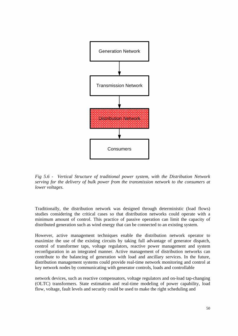
50
Generation Network
Distribution Network
Transmission Network
Consumers
Fig 5.6 - Vertical Structure of traditional power system, with the Distribution Network serving for the delivery of bulk power from the transmission network to the consumers at lower voltages. Traditionally, the distribution network was designed through deterministic (load flows) studies considering the critical cases so that distribution networks could operate with a minimum amount of control. This practice of passive operation can limit the capacity of distributed generation such as wind energy that can be connected to an existing system. However, active management techniques enable the distribution network operator to maximize the use of the existing circuits by taking full advantage of generator dispatch, control of transformer taps, voltage regulators, reactive power management and system reconfiguration in an integrated manner. Active management of distribution networks can contribute to the balancing of generation with load and ancillary services. In the future, distribution management systems could provide real-time network monitoring and control at key network nodes by communicating with generator controls, loads and controllable network devices, such as reactive compensators, voltage regulators and on-load tap-changing (OLTC) transformers. State estimation and real-time modeling of power capability, load flow, voltage, fault levels and security could be used to make the right scheduling and
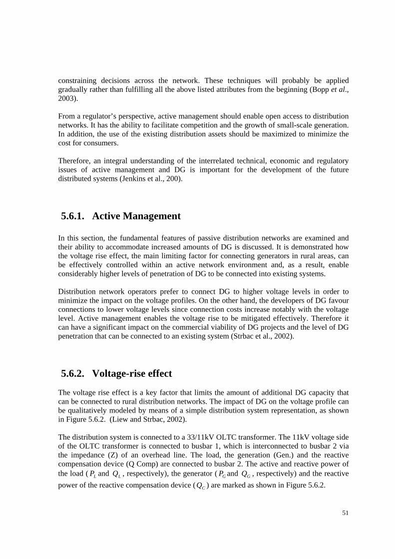
51
constraining decisions across the network. These techniques will probably be applied gradually rather than fulfilling all the above listed attributes from the beginning (Bopp et al., 2003). From a regulator’s perspective, active management should enable open access to distribution networks. It has the ability to facilitate competition and the growth of small-scale generation. In addition, the use of the existing distribution assets should be maximized to minimize the cost for consumers. Therefore, an integral understanding of the interrelated technical, economic and regulatory issues of active management and DG is important for the development of the future distributed systems (Jenkins et al., 200). 5.6.1. Active Management
In this section, the fundamental features of passive distribution networks are examined and their ability to accommodate increased amounts of DG is discussed. It is demonstrated how the voltage rise effect, the main limiting factor for connecting generators in rural areas, can be effectively controlled within an active network environment and, as a result, enable considerably higher levels of penetration of DG to be connected into existing systems. Distribution network operators prefer to connect DG to higher voltage levels in order to minimize the impact on the voltage profiles. On the other hand, the developers of DG favour connections to lower voltage levels since connection costs increase notably with the voltage level. Active management enables the voltage rise to be mitigated effectively. Therefore it can have a significant impact on the commercial viability of DG projects and the level of DG penetration that can be connected to an existing system (Strbac et al., 2002). 5.6.2. Voltage-rise effect
The voltage rise effect is a key factor that limits the amount of additional DG capacity that can be connected to rural distribution networks. The impact of DG on the voltage profile can be qualitatively modeled by means of a simple distribution system representation, as shown in Figure 5.6.2. (Liew and Strbac, 2002). The distribution system is connected to a 33/11kV OLTC transformer. The 11kV voltage side of the OLTC transformer is connected to busbar 1, which is interconnected to busbar 2 via the impedance (Z) of an overhead line. The load, the generation (Gen.) and the reactive compensation device (Q Comp) are connected to busbar 2. The active and reactive power of the load ( LP and LQ , respectively), the generator ( GP and GQ , respectively) and the reactive power of the reactive compensation device ( CQ ) are marked as shown in Figure 5.6.2.
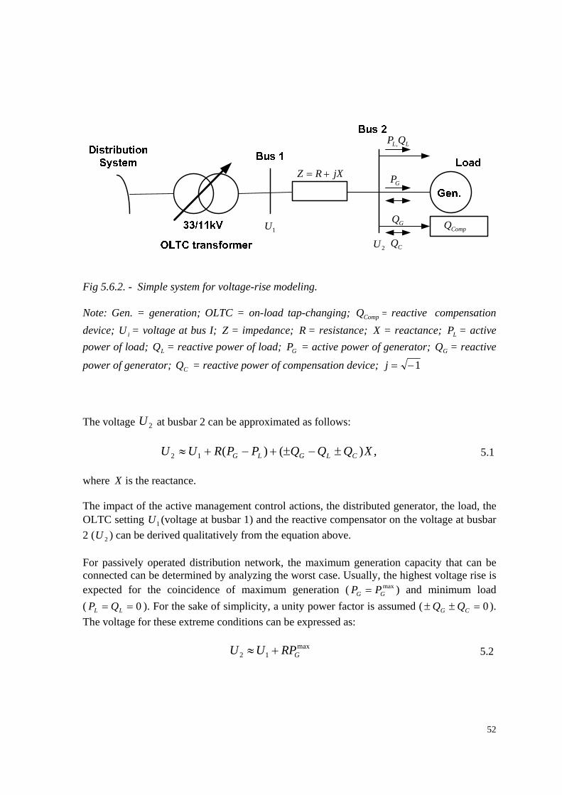
52
1U
2U
LL QP ,
GP
GQ
CQCompQ
jXRZ +=
Fig 5.6.2. - Simple system for voltage-rise modeling. Note: Gen. = generation; OLTC = on-load tap-changing; CompQ = reactive compensation device; iU = voltage at bus I; Z = impedance; R = resistance; X = reactance; LP = active power of load; LQ = reactive power of load; GP = active power of generator; GQ = reactive
power of generator; CQ = reactive power of compensation device; 1−=j The voltage 2U at busbar 2 can be approximated as follows: ,)()(12 XQQQPPRUU CLGLG ±−±+−+≈ 5.1 where X is the reactance. The impact of the active management control actions, the distributed generator, the load, the OLTC setting 1U (voltage at busbar 1) and the reactive compensator on the voltage at busbar 2 ( 2U ) can be derived qualitatively from the equation above. For passively operated distribution network, the maximum generation capacity that can be connected can be determined by analyzing the worst case. Usually, the highest voltage rise is expected for the coincidence of maximum generation ( max
GG PP = ) and minimum load ( 0== LL QP ). For the sake of simplicity, a unity power factor is assumed ( 0=±± CG QQ ). The voltage for these extreme conditions can be expressed as: max
12 GRPUU +≈ 5.2
53
The maximum capacity of generation that can be connected to busbar 2 is limited by the maximum allowed voltage at busbar 2, max
2U . This can be seen from Equation 5.2
R
UUPG1
max2max −
≤ 5.3
Another important parameter that determines the maximum permissible generation capacity is the resistance, R , of the network impedance, Z . The reactance, X , does not need to be considered in the formula as long as unity power factor operation of the generator is assumed. In this context, it should be mentioned that the voltage rise or drop can be mitigated by reducing the network impedance. This can be achieved by network reinforcement. 5.7. Danish Case Study So far, in the chapter, we have dealt wih various issues related to the interaction of wind power plants with the electricity network. Issues which include: active power control, the impact of wind power on voltage control, the importance of wind turbine voltge control capabilities, etc had been highlighted. This section focuses on real life observation of loss of large amounts of distributed generation (DG) which include wind power in the medium and low-voltage distribution grids due to faults on the high voltage transmission grid of western Denmark[8]. The study is important because the structure of the system conforms to the presnt structure of power system due to deregulation as the classical centralized generation system is transformed to a completely decentralized generation system with lots of distributed generators including wind power. Worthy of mention is the fact that the installed generation capacity at the distribution level now exceeds the generation capacity at the transmission level and this shift is expected to continue in the future. Presently, the operation of the power system relies on the ancillary services provided by the conventional generation units. Ideally, it must be possible to operate the decentralized power system without any conventional generation. To achieve this, the whole operating concept has to be revised to deal with such situation. This requires a major effort which can only be implemented gradually in order to uphold the security of supply. The striking aspect of the present classical protection concept of the distributed synchronous machines leads to non-selectiv etripping of the units. In the fully decentralized generation system of western Denmark, shuch uncontrolled loss of large amounts of distributed generation has become a problem to the safe operation of the system. A study of the problem of tripping distributed generation due to faults in the transmission gird is seen as a first step towards enabling the distributed networks to participate more actively in the power system operation.
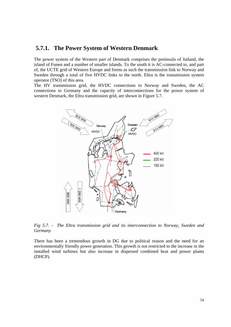
54
5.7.1. The Power System of Western Denmark
The power system of the Western part of Denmark comprises the peninsula of Jutland, the island of Funen and a number of smaller islands. To the south it is AC-connected to, and part of, the UCTE grid of Western Europe and forms as such the transmission link to Norway and Sweden through a total of five HVDC links to the north. Eltra is the transmission system operator (TSO) of this area. The HV transmission grid, the HVDC connections to Norway and Sweden, the AC connections to Germany and the capacity of interconnections for the power system of western Denmark, the Eltra transmission grid, are shown in Figure 5.7.
Fig 5.7. - The Eltra transmission grid and its interconnection to Norway, Sweden and Germany There has been a tremendous growth in DG due to political reason and the need for an environmentally friendly power generation. This growth is not restricted to the increase in the installed wind turbines but also increase in dispersed combined heat and power plants (DHCP).

55
5.7.2. Loss of Distributed Generation
There has been a growing problem in the power system as a result of the loss of large amount of the Distributed generation due to severe faults on the HV transmission grid. This implies both loss of voltage support during and after the transient transition as well as loss of an unknown but large amount of power production. It was also observed that some DG units are more prone to tripping than others. It is generally assumed that the main cause of tripping large numbers of DHCP units during grid faults is high settings of the voltage trip value of the ynchromous undervoltage relays of the generator protection system. The discussion of proper settings of the synchronous undervoltage relay of DCHP units has two sides. On the one side, the TSO has the responsibility of the overall stable operation of the power system. Hence the TSO would like as many synchronous machines as possible to ride through faults in the system in order to provide voltage support and to minimise loss of production. On the other side, the owners of the generators bear the responsibility of protecting their units from breakdowns. This is especially a problem in MV distribution grids where a DHCP unit risks being islanded without knowing it during a grid fault being automatically tripped by e.g. line distance relays. A situation which could become catastrophic if the DG faces an asynchronous reconnection to the power system with consequences for the generator and prime mover shaft depending on the phase displacement between the power system and the unintentionally created island. The worst case being a reconnection in °180 phase opposition.
5.7.3. The Incident A crane hit the phase conductors of a 150kV transmission line on Monday, January 12, 2004. The incident led to a sequence of faults from single phase to ground, then a two-phase to ground and finally a three-phase short circuit fault resulting in permanent tripping of the faulted line. The incident was measured by a fast transient recorder in a new 150 kV substation as shown in Figure 5.7.3. One of the consequences of the fault was the tripping of about 18 DCHP units scattered throughout the power system and the loss of their power production totaling 240 MW. The incident itself was not a dangerous event to the transmission system as the transmission system was designed to withstand the loss of a 600MW generator. However, a study was initiated because of the observed continuous loss of large amount power production as a result of grid faults in the transmission system.

56
Fig 5.7.3. - Phase voltages measured in substation KAE3 during the grid fault on 12, January 2004 5.7.4. The Case Study
The study noted that it would be very difficult to try to set up and perform a transient simulation of the actual non-symmetrical fault sequence inclusive of the complicated non-symmetrical relay reactions. It was moreover expected that the tripping of the DCHP units to a large degree was caused by the synchronous undervoltage relay of the protection system of each generator of each DCHP plant. It was thus assumed that the actual tripping was due to the final three-phase short-circuit causing by far the largest voltage drop. Hence the study was restricted to perform a dynamic simulation of a three-phase short-circuit on the actual transmission line with permanent tripping of the faulted line after 86ms. as was the actual recorded tripping time. Eltra utilizes the PowerFactory power system analysis software of the German company DigiSilent. In order to be able to set up any grid cse for analysis in a fast and efficient way, Eltra ha developed an in-house software that links SCADA system stored state measurements of the transmission system, power production of all types and sizes of generators and the Eltra in-house off-line grid database to PowerFactory. Hence Eltra is capable of setting up a complete model of the transmission system of Western Denmark as it was operated in steady state a few minutes prior to the fault. Using the model which has a total of 86 generating units, a dynamic simulation of a three-phase short-circuit on the actual transmission line was performed. The faulted line and the short-circuit was tripped after 86ms as was the case in real event.
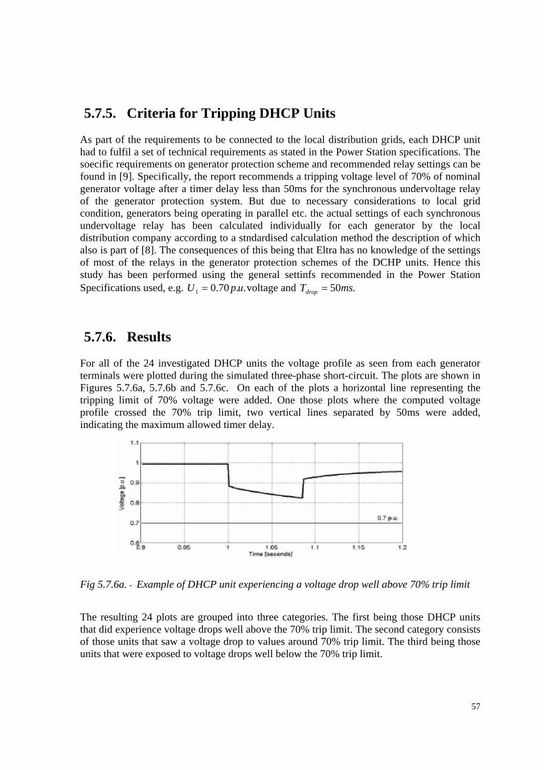
57
5.7.5. Criteria for Tripping DHCP Units
As part of the requirements to be connected to the local distribution grids, each DHCP unit had to fulfil a set of technical requirements as stated in the Power Station specifications. The soecific requirements on generator protection scheme and recommended relay settings can be found in [9]. Specifically, the report recommends a tripping voltage level of 70% of nominal generator voltage after a timer delay less than 50ms for the synchronous undervoltage relay of the generator protection system. But due to necessary considerations to local grid condition, generators being operating in parallel etc. the actual settings of each synchronous undervoltage relay has been calculated individually for each generator by the local distribution company according to a stndardised calculation method the description of which also is part of [8]. The consequences of this being that Eltra has no knowledge of the settings of most of the relays in the generator protection schemes of the DCHP units. Hence this study has been performed using the general settinfs recommended in the Power Station Specifications used, e.g. ..70.01 upU = voltage and .50msTdrop =
5.7.6. Results For all of the 24 investigated DHCP units the voltage profile as seen from each generator terminals were plotted during the simulated three-phase short-circuit. The plots are shown in Figures 5.7.6a, 5.7.6b and 5.7.6c. On each of the plots a horizontal line representing the tripping limit of 70% voltage were added. One those plots where the computed voltage profile crossed the 70% trip limit, two vertical lines separated by 50ms were added, indicating the maximum allowed timer delay. Fig 5.7.6a. - Example of DHCP unit experiencing a voltage drop well above 70% trip limit The resulting 24 plots are grouped into three categories. The first being those DHCP units that did experience voltage drops well above the 70% trip limit. The second category consists of those units that saw a voltage drop to values around 70% trip limit. The third being those units that were exposed to voltage drops well below the 70% trip limit.
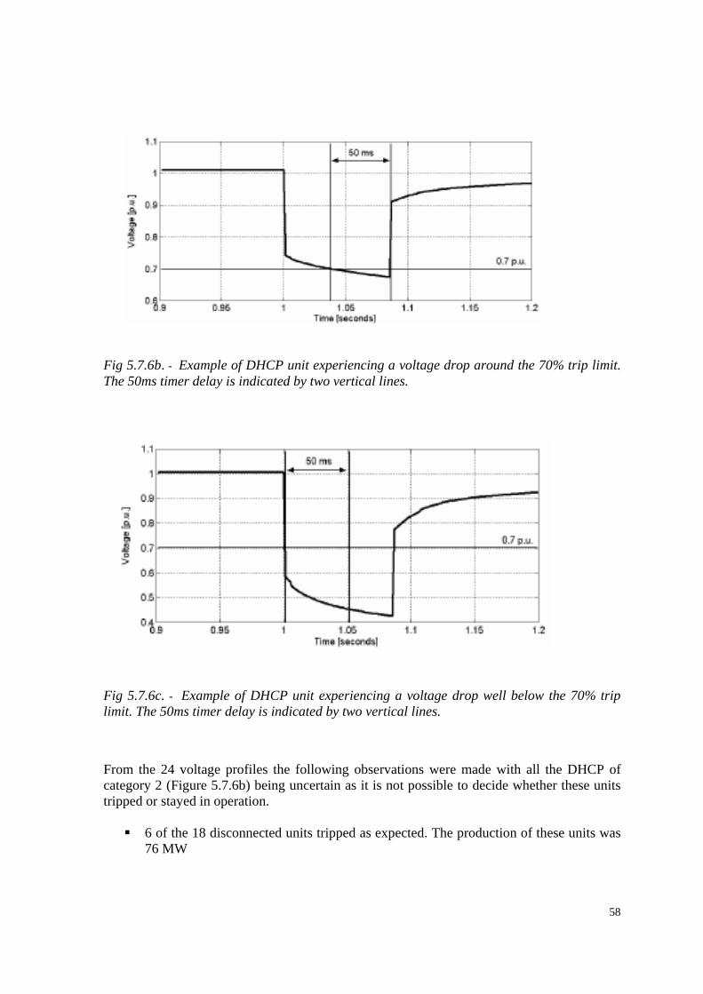
58
Fig 5.7.6b. - Example of DHCP unit experiencing a voltage drop around the 70% trip limit. The 50ms timer delay is indicated by two vertical lines.
Fig 5.7.6c. - Example of DHCP unit experiencing a voltage drop well below the 70% trip limit. The 50ms timer delay is indicated by two vertical lines. From the 24 voltage profiles the following observations were made with all the DHCP of category 2 (Figure 5.7.6b) being uncertain as it is not possible to decide whether these units tripped or stayed in operation.
6 of the 18 disconnected units tripped as expected. The production of these units was 76 MW
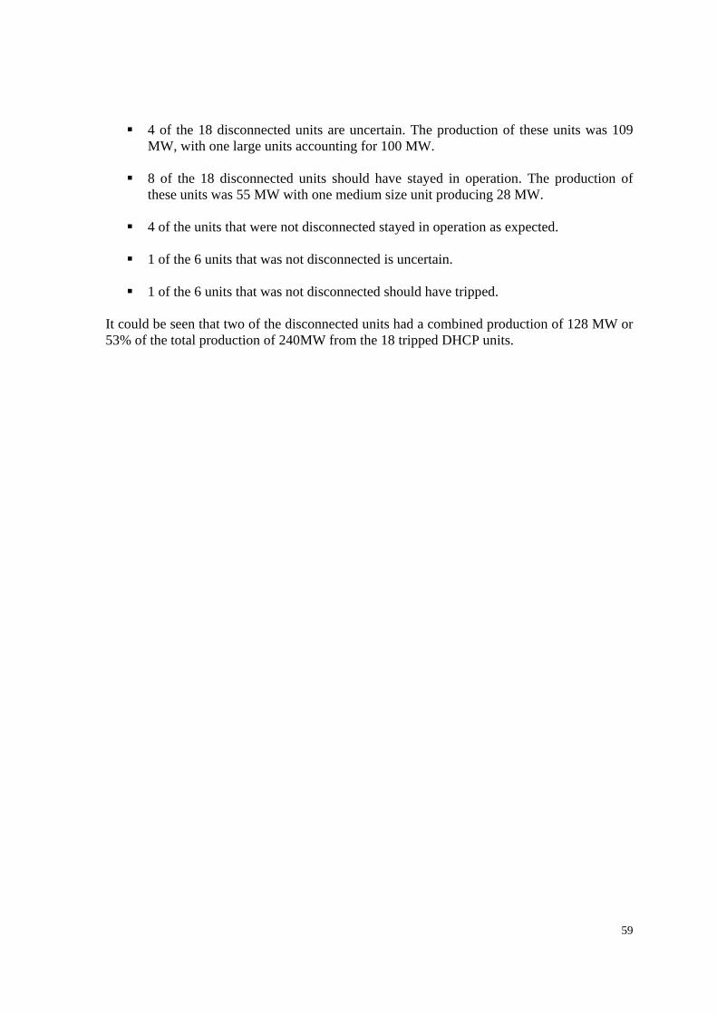
59
4 of the 18 disconnected units are uncertain. The production of these units was 109 MW, with one large units accounting for 100 MW.
8 of the 18 disconnected units should have stayed in operation. The production of
these units was 55 MW with one medium size unit producing 28 MW.
4 of the units that were not disconnected stayed in operation as expected.
1 of the 6 units that was not disconnected is uncertain.
1 of the 6 units that was not disconnected should have tripped. It could be seen that two of the disconnected units had a combined production of 128 MW or 53% of the total production of 240MW from the 18 tripped DHCP units.
60
Conclusion Generally, the generation of electrical energy has been altered by the introduction of an increasing number of wind generated electricity with characteristics that are different from those of conventional power plants. Large thermal power stations require many hours after a breakdown before they can resume operation. As opposed to this, wind turbines are able to resynchronise themselves with the network and provide active power in accordance with the prescribed index values after a short interval (e.g. spinning reserve, power frequency regulation, voltage regulation and supply of reactive power). Conventional power stations are able to contribute during several seconds substantially to short-circuit power, because of their rotating centrifugal masses, which both maintains voltage levels and ensures network protection functionality. The increase penetration of wind energy and other DCHP units in the medium and low voltage is as a result of deregulation of the power sector. The Danish case study discussed earlier presents some of the consequencies of the increase in wind energy penetration in our power system of today. The conclusions from the study is as follows: The fault in the 150 kV transmission grid led to the tripping of 18 DHCP units with total production of 240 MW throughout the MV and LV distribution grids. The study suggest that at least 45% of the units should have stayed on-line. These results give reason to believe that the synchronous undervoltage relay of each generator protection system may have been set to a high trip value (well above the recommended 70% of nominal generator voltage). The study also shows that at least 1 of the investigated 6 DHCP units that stayed on-line should have tripped. Consequently, it has been recommended to initiate an investigation of the extent of present generator protection schemes of DCHP units, actual settings of the different types of relays and recalculation of the relay settings. Moreover and most promising, the study must include redesigning of the generator protection schemes of DCHP units and the relay protection schemes of the local distribution grid seen as a hole. Doing so, promising ideas exist of reducing the risk of islanding unintentionally DCHP units. Thus providing the DCHP unit owner with the incentive to lower the voltage trip limit setting of the synchronous undervoltage relay. In grids where wind energy generation is spread out over a large area and conventional generation from large power stations is simultaneously reduced, severe voltage drops and frequency fluctuations are more likely if the short-circuit capacity is decreased. This leads to both a loss of voltage stability and the selective operation of the network protection systems. Special attention has to be paid to the dynamic behaviour of wind turbines in the event of network failures. These facts make it necessary to define new grid requirements, particularly for wind turbines, in order to include them in the network regulation mechanism. These additional requirements have to take into account the technical standard of decentralised
61
energy supplies, in contrast to conventional power stations. Such additional requirements will help to guarantee a stable and secure grid operation It is equally of note that despite the attendant problems associated with this new energy production scheme, there has been continued increases in their penetration level, which suggests a great promise for the future of energy production with renewable energy generation scheme such as wind enrgy especially with the ever uncertainties surrounding fossil fuel for conventional generation schemes such as gas and crude oil globally. .
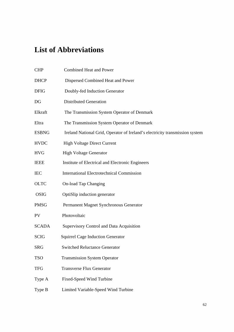
62
List of Abbreviations CHP Combined Heat and Power DHCP Dispersed Combined Heat and Power DFIG Doubly-fed Induction Generator DG Distributed Generation Elkraft The Transmission System Operator of Denmark Eltra The Transmission System Operator of Denmark ESBNG Ireland National Grid, Operator of Ireland’s electricity transmission system HVDC High Voltage Direct Current HVG High Voltage Generator IEEE Institute of Electrical and Electronic Engineers IEC International Electrotechnical Commission OLTC On-load Tap Changing OSIG OptiSlip induction generator PMSG Permanent Magnet Synchronous Generator PV Photovoltaic SCADA Supervisory Control and Data Acquisition SCIG Squirrel Cage Induction Generator SRG Switched Reluctance Generator TSO Transmission System Operator TFG Transverse Flux Generator Type A Fixed-Speed Wind Turbine Type B Limited Variable-Speed Wind Turbine
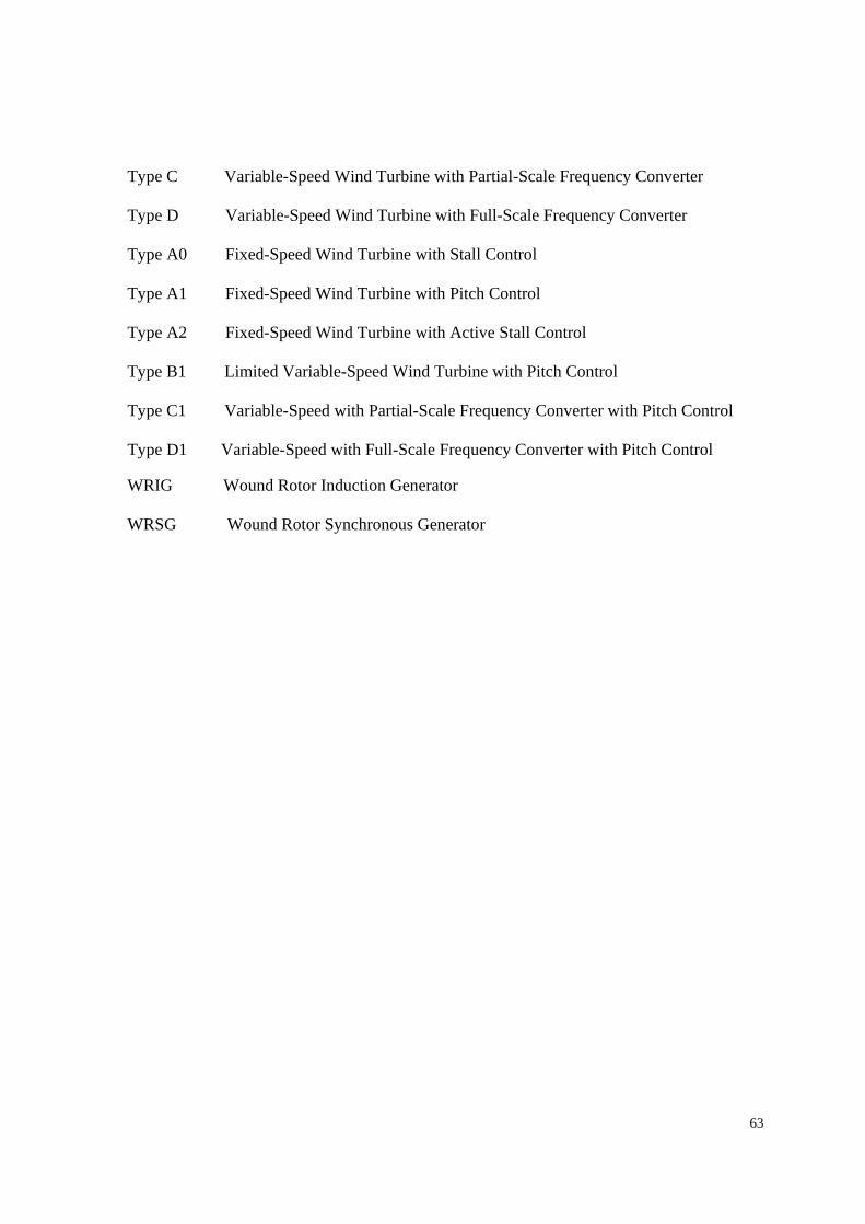
63
Type C Variable-Speed Wind Turbine with Partial-Scale Frequency Converter Type D Variable-Speed Wind Turbine with Full-Scale Frequency Converter Type A0 Fixed-Speed Wind Turbine with Stall Control Type A1 Fixed-Speed Wind Turbine with Pitch Control Type A2 Fixed-Speed Wind Turbine with Active Stall Control Type B1 Limited Variable-Speed Wind Turbine with Pitch Control Type C1 Variable-Speed with Partial-Scale Frequency Converter with Pitch Control Type D1 Variable-Speed with Full-Scale Frequency Converter with Pitch Control WRIG Wound Rotor Induction Generator WRSG Wound Rotor Synchronous Generator
64
References [1] Global Wind Energy Council (GWEC) [2] Wind Power in Power Systems by Thomas Ackermann(2005) [3] Wind Turbine Grid Connection and Interaction - Deutsches Windenergie-Institut GmbH Germany [4] IEC 61000-4-15 [5] Ekraft and Eltra – Technical regulations for the properties and control of wind turbines connected to grids with voltages below 100KV –may, 2004 [6] ESB NG – Draft proposal for the connection and operation of wind farm (ESBNG, 2002a). [7] ‘Wind turbine Generators Connected to Networks with Voltage Levels below 100kV (Draft)’ (DEFU, 2003) [8] Losss of Distributed Generation by Grid Faults – A Danish Case Study by Per Lund, Hans Abildgaard and Vladislav Akhmatov [9] “Relay Protection of Distributed Production Units based on Synchronous Generators”, DEFU Technical Report 293, 2.edition, June 1995. DEFU, Technical Research Institute for Danish Electric Utilities.