wind generator monitoring and control system_jakab zsolt
TRANSCRIPT
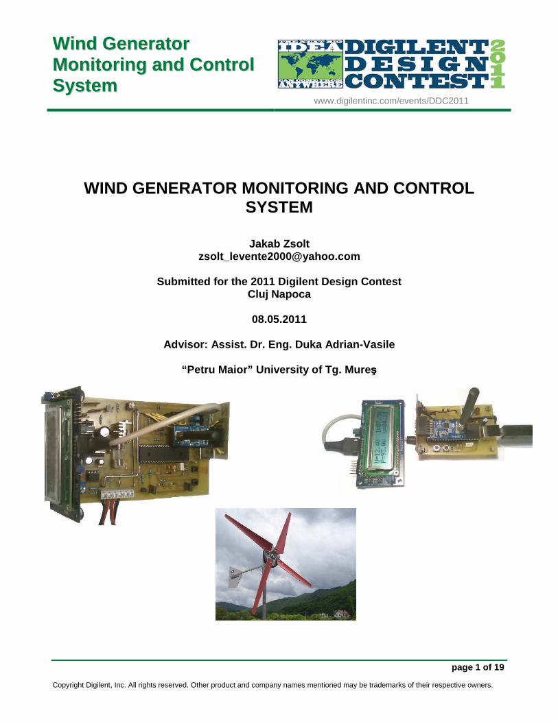
WWiinndd GGeenneerraattoorr MMoonnii ttoorr iinngg aanndd CCoonnttrrooll SSyysstteemm
www.digilentinc.com/events/DDC2011
page 1 of 19
Copyright Digilent, Inc. All rights reserved. Other product and company names mentioned may be trademarks of their respective owners.
WIND GENERATOR MONITORING AND CONTROL SYSTEM
Jakab Zsolt [email protected]
Submitted for the 2011 Digilent Design Contest
Cluj Napoca
08.05.2011
Advisor: Assist. Dr. Eng. Duka Adrian-Vasile
“Petru Maior” University of Tg. Mure ş
Wind Generator Monitoring and Control System Design Report
www.digilentinc.com page 2 of 19 Copyright Digilent, Inc. All rights reserved. Other product and company names mentioned may be trademarks of their respective owners.
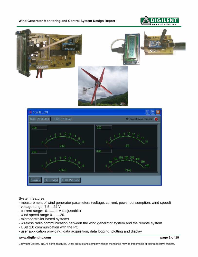
System features - measurement of wind generator parameters (voltage, current, power consumption, wind speed) - voltage range: 7.5....24 V - current range: 0.1....11 A (adjustable) - wind speed range 0…….20. - microcontroller based systems - wireless radio communication between the wind generator system and the remote system - USB 2.0 communication with the PC - user application providing: data acquisition, data logging, plotting and display
Wind Generator Monitoring and Control System Design Report
www.digilentinc.com page 3 of 19 Copyright Digilent, Inc. All rights reserved. Other product and company names mentioned may be trademarks of their respective owners.
Project Summary
1. Introduction
1.1 Problem to solve
1.2 Proposed solution
2. Hardware description
2.1 Wind generator system
2.2 Remote station
3. Software
3.1 Communication
3.2 Microcontroller applications
3.2 LabWindows CVI user interface Digilent Products Required
• 2 x PmodCLS
• 2 x PmodRF1

Wind Generator Monitoring and Control System Design Report
www.digilentinc.com page 4 of 19 Copyright Digilent, Inc. All rights reserved. Other product and company names mentioned may be trademarks of their respective owners.
1. Introduction
1.1 Problem to solve
Small wind generators up to hundreds of watts work in parallel with chemical
batteries on 12 V, 24V or 48V direct current bus bar systems. A.C. consumers take
energy from these systems through inverters.
Wind generators deliver energy when wind speed exceeds a certain threshold
value prox. 3 - 5 m/s depending on the wind generator size. If wind energy is absent for
longer time, the accumulators start to discharge, and at a certain value the consumers
need to be disconnected from the d.c. bus bar and to be connected to other energy
sources, if available, in order to avoid damage in the energy storage system .This kind
of transition between energy sources can cause long interrupts in the consumers
operation, or even permanent shutdown.
In this conditions the main problem is the instability regarding the power
supplied by a small wind generator.
1.2 Proposed solution
In the idea of a parallel operation between a renewable energy source and a
relatively secure energy source, such as the public electric network, I suggest the
following monitoring and control system for a wind generator, built around Microchip
PIC microcontrollers:
Wind Generator Monitoring and Control System Design Report
www.digilentinc.com page 5 of 19 Copyright Digilent, Inc. All rights reserved. Other product and company names mentioned may be trademarks of their respective owners.
2. Hardware description
The Wind Generator Monitoring and Control System is based on two subsystems: one
located near the wind generator and the other one placed away from the wind
generator’s site. These components are named:
- The wind generator system
- Remote system/station
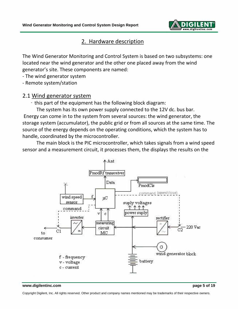
2.1 Wind generator system - this part of the equipment has the following block diagram:
The system has its own power supply connected to the 12V dc. bus bar.
Energy can come in to the system from several sources: the wind generator, the
storage system (accumulator), the public grid or from all sources at the same time. The
source of the energy depends on the operating conditions, which the system has to
handle, coordinated by the microcontroller.
The main block is the PIC microcontroller, which takes signals from a wind speed
sensor and a measurement circuit, it processes them, the displays the results on the
Wind Generator Monitoring and Control System Design Report
www.digilentinc.com page 6 of 19 Copyright Digilent, Inc. All rights reserved. Other product and company names mentioned may be trademarks of their respective owners.
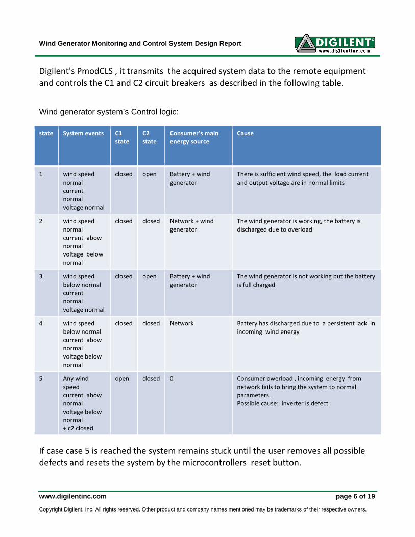
Digilent's PmodCLS , it transmits the acquired system data to the remote equipment
and controls the C1 and C2 circuit breakers as described in the following table.
Wind generator system’s Control logic: state System events C1
state C2 state
Consumer’s main
energy source Cause
1 wind speed
normal current
normal voltage normal
closed open Battery + wind
generator There is sufficient wind speed, the load current
and output voltage are in normal limits
2 wind speed
normal current abow
normal voltage below
normal
closed closed Network + wind
generator The wind generator is working, the battery is
discharged due to overload
3 wind speed
below normal current
normal voltage normal
closed open Battery + wind
generator The wind generator is not working but the battery
is full charged
4 wind speed
below normal current abow
normal voltage below
normal
closed closed Network Battery has discharged due to a persistent lack in
incoming wind energy
5 Any wind
speed current abow
normal voltage below
normal + c2 closed
open closed 0 Consumer owerload , incoming energy from
network fails to bring the system to normal
parameters. Possible cause: inverter is defect
If case case 5 is reached the system remains stuck until the user removes all possible
defects and resets the system by the microcontrollers reset button.
Wind Generator Monitoring and Control System Design Report
www.digilentinc.com page 7 of 19 Copyright Digilent, Inc. All rights reserved. Other product and company names mentioned may be trademarks of their respective owners.
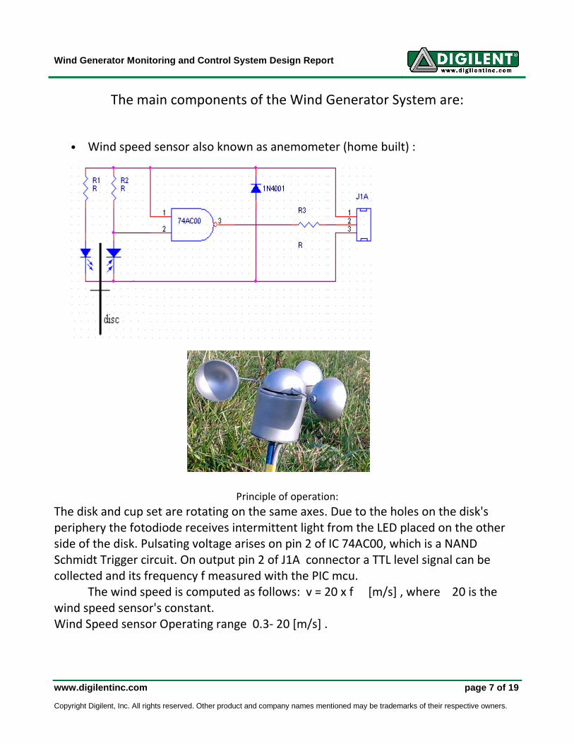
The main components of the Wind Generator System are:
• Wind speed sensor also known as anemometer (home built) :
Principle of operation:
The disk and cup set are rotating on the same axes. Due to the holes on the disk's
periphery the fotodiode receives intermittent light from the LED placed on the other
side of the disk. Pulsating voltage arises on pin 2 of IC 74AC00, which is a NAND
Schmidt Trigger circuit. On output pin 2 of J1A connector a TTL level signal can be
collected and its frequency f measured with the PIC mcu.
The wind speed is computed as follows: v = 20 x f [m/s] , where 20 is the
wind speed sensor's constant.
Wind Speed sensor Operating range 0.3- 20 [m/s] .

Wind Generator Monitoring and Control System Design Report
www.digilentinc.com page 8 of 19 Copyright Digilent, Inc. All rights reserved. Other product and company names mentioned may be trademarks of their respective owners.
• Power suply and measurement circuit
Supply voltage from dc. bus bar is applied to the main stabilizer IC 7805. To avoid
linking power supply against bus bar, polarization diode 1N 4148 was introduced after
a 250 mA fuse. When wrong connected the diode enters in conduction and short
circuits the fuse so the circuit is interrupted and no damage is produced.
IC 7805 assures the power supply for the PIC microcomtroller, anemometer,
relays, a 15 V double source for measuring circuit and a 3.3V source for PmodCLS and
PmodRf1.
The 15 V double source uses a d.c-d.c. converter to obtain the necessary
voltages for the LM 324 operational amplifier (op.amp.). The heart of the converter is a
classic astable configuration of two NPN transistors with the primary windings of the
transformer and a few discrete circuit components. 1N4148 fast switching diodes are
used to eliminate autoinduction spikes.
To measure the current one op.amp. with an amplification of approx. 100 is used
to get the voltage drop on the 0.0049 Ω shunt resistor.
Voltage on bus bar is measured using a voltage divider made using 10 kΩ and 33 kΩ
resistors.
The operating ranges for the measurement circuit are: voltage 7.5÷24 V, current 0.1÷
11 A
If malfunction occurs the outputs of the measurement circuit can't override
Wind Generator Monitoring and Control System Design Report
www.digilentinc.com page 9 of 19 Copyright Digilent, Inc. All rights reserved. Other product and company names mentioned may be trademarks of their respective owners.
standard TTL level due to the use of 5V Zenner diodes connected on them. Also 10nF
capacitors are used to ground a.c. noise signals that may appear during wind generator
function.
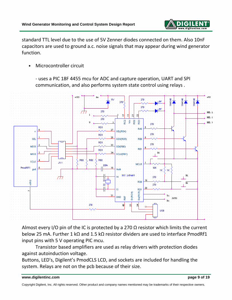
• Microcontroller circuit
- uses a PIC 18F 4455 mcu for ADC and capture operation, UART and SPI
communication, and also performs system state control using relays .
Almost every I/O pin of the IC is protected by a 270 Ω resistor which limits the current
below 25 mA. Further 1 kΩ and 1.5 kΩ resistor dividers are used to interface PmodRf1
input pins with 5 V operating PIC mcu.
Transistor based amplifiers are used as relay drivers with protection diodes
against autoinduction voltage.
Buttons, LED's, Digilent’s PmodCLS LCD, and sockets are included for handling the
system. Relays are not on the pcb because of their size.
Wind Generator Monitoring and Control System Design Report
www.digilentinc.com page 10 of 19 Copyright Digilent, Inc. All rights reserved. Other product and company names mentioned may be trademarks of their respective owners.
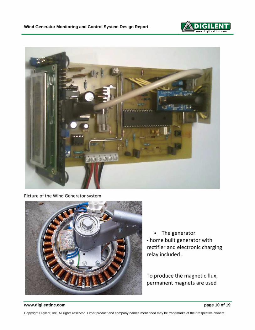
Picture of the Wind Generator system
• The generator
- home built generator with
rectifier and electronic charging
relay included .
To produce the magnetic flux,
permanent magnets are used

Wind Generator Monitoring and Control System Design Report
www.digilentinc.com page 11 of 19 Copyright Digilent, Inc. All rights reserved. Other product and company names mentioned may be trademarks of their respective owners.
The power supplied by this generator is up to 400W depending on the speed of
the wind. The system was tested by the author up to a power of 250W (v=5m/s)
Wind Generator Monitoring and Control System Design Report
www.digilentinc.com page 12 of 19 Copyright Digilent, Inc. All rights reserved. Other product and company names mentioned may be trademarks of their respective owners.
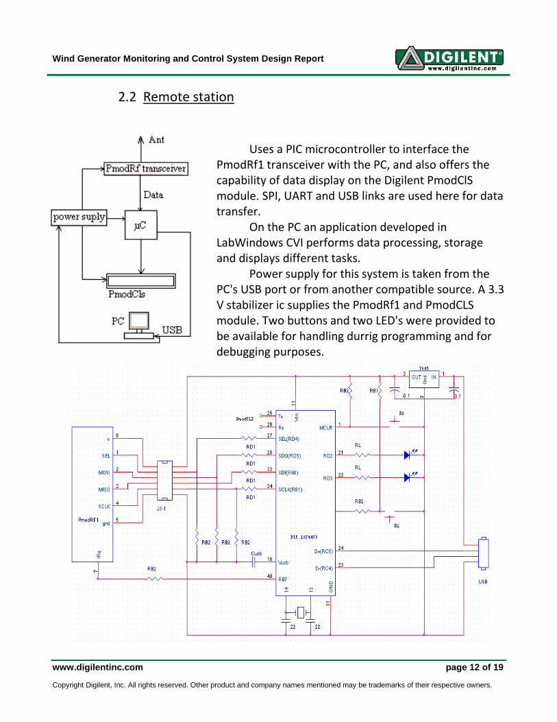
2.2 Remote station
Uses a PIC microcontroller to interface the
PmodRf1 transceiver with the PC, and also offers the
capability of data display on the Digilent PmodClS
module. SPI, UART and USB links are used here for data
transfer.
On the PC an application developed in
LabWindows CVI performs data processing, storage
and displays different tasks. Power supply for this system is taken from the
PC's USB port or from another compatible source. A 3.3
V stabilizer ic supplies the PmodRf1 and PmodCLS
module. Two buttons and two LED's were provided to
be available for handling durrig programming and for
debugging purposes.
Wind Generator Monitoring and Control System Design Report
www.digilentinc.com page 13 of 19 Copyright Digilent, Inc. All rights reserved. Other product and company names mentioned may be trademarks of their respective owners.
3. Software
3.1 Comunication
UART, SPI, USB and Radio link communication were implemented as follows:
- between both PIC mcu's and PmodCLS's a 32 byte data packet is transmitted with
UART protocol;
- between both PIC mcu's and the Digilent PmodRF1's , an software implemented SPI
interface is used
- between the remote station and the PC an USB connection is used
- between the wind generator system and the remote station a unidirectional radio link
is used for the data transfer
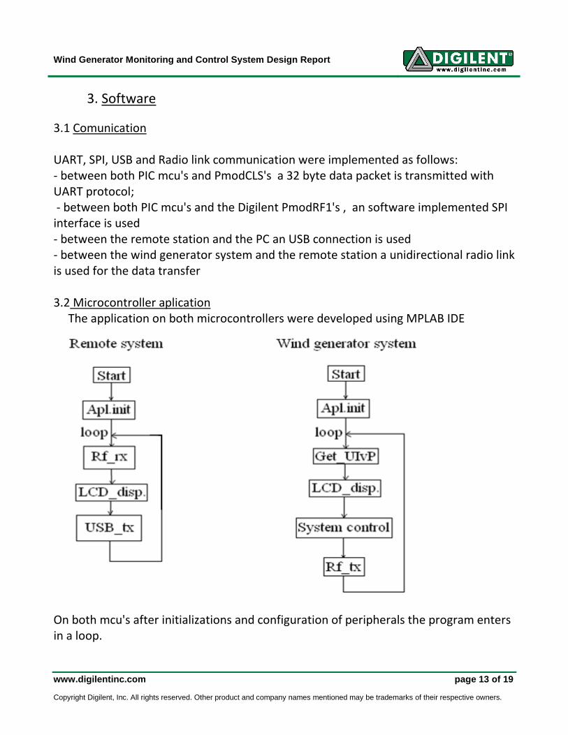
3.2 Microcontroller aplication
The application on both microcontrollers were developed using MPLAB IDE
On both mcu's after initializations and configuration of peripherals the program enters
in a loop.
Wind Generator Monitoring and Control System Design Report
www.digilentinc.com page 14 of 19 Copyright Digilent, Inc. All rights reserved. Other product and company names mentioned may be trademarks of their respective owners.
On the remote system's mcu the loop starts with the reception of data from the
radio link. If there is no data available the system displays "No data" and if 32 byte
data package is received the voltage, current ,power, and wind speed numerical values
are displayed.
In 1 sec. time periods (by testing Timer0 IF flag bit) USB data transmission to Pc is
executed.
On the wind generator system's mcu the loop begins with the data acquisition,
then the voltage, current, power and wind speed values are displayed. After that, the
mcu checks if the values are within their normal limits and if not it tries to establish the
normal parameters in the circuit by controlling the circuit breakers. After performing
system control the mcu sends the data to the remote station using the PmodRf1.
This loop is not infinite. If the mcu can't bring back the system to its normal
parameters within 1 min. from its first action on the circuit breaker (C2), the loop
stops at the system’s command and removes the load from 12V bus bar through C1
circuit breaker.
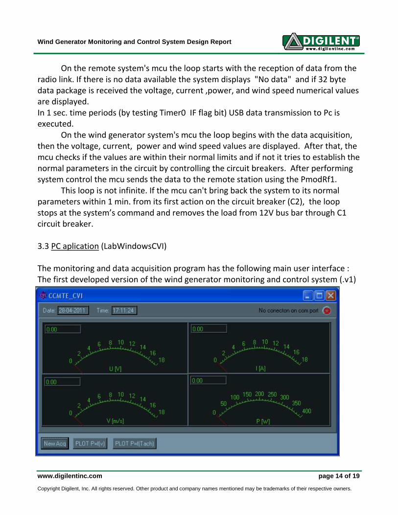
3.3 PC aplication (LabWindowsCVI)
The monitoring and data acquisition program has the following main user interface :
The first developed version of the wind generator monitoring and control system (.v1)
Wind Generator Monitoring and Control System Design Report
www.digilentinc.com page 15 of 19 Copyright Digilent, Inc. All rights reserved. Other product and company names mentioned may be trademarks of their respective owners.
uses wired UART communication (a cable connection) between Pc and the generator
system. The final version of the system (.v3) uses a virtual USB com port based on a
firmware provided by Microchip for PIC controllers. This means that the
communication with new system is possible without major hardware or software
impact.
The main user interface contains 4 analog and 4 digital measuring instruments,
text messages, LEDs, buttons and also displays the current time and date.
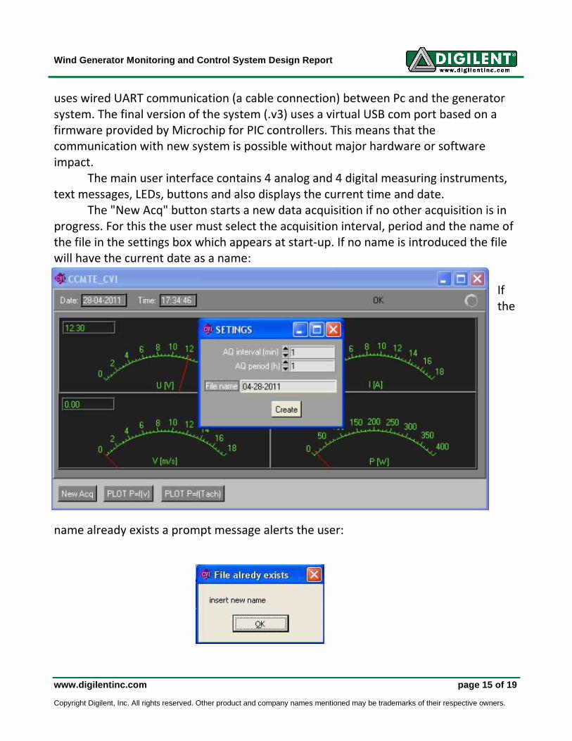
The "New Acq" button starts a new data acquisition if no other acquisition is in
progress. For this the user must select the acquisition interval, period and the name of
the file in the settings box which appears at start-up. If no name is introduced the file
will have the current date as a name:
If
the
name already exists a prompt message alerts the user:
Wind Generator Monitoring and Control System Design Report
www.digilentinc.com page 16 of 19 Copyright Digilent, Inc. All rights reserved. Other product and company names mentioned may be trademarks of their respective owners.
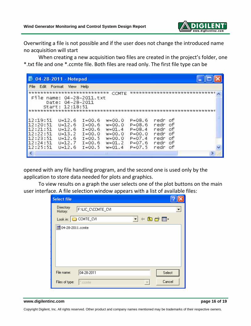
Overwriting a file is not possible and if the user does not change the introduced name
no acquisition will start
When creating a new acquisition two files are created in the project’s folder, one
*.txt file and one *.ccmte file. Both files are read only. The first file type can be
opened with any file handling program, and the second one is used only by the
application to store data needed for plots and graphics.
To view results on a graph the user selects one of the plot buttons on the main
user interface. A file selection window appears with a list of available files:
Wind Generator Monitoring and Control System Design Report
www.digilentinc.com page 17 of 19 Copyright Digilent, Inc. All rights reserved. Other product and company names mentioned may be trademarks of their respective owners.
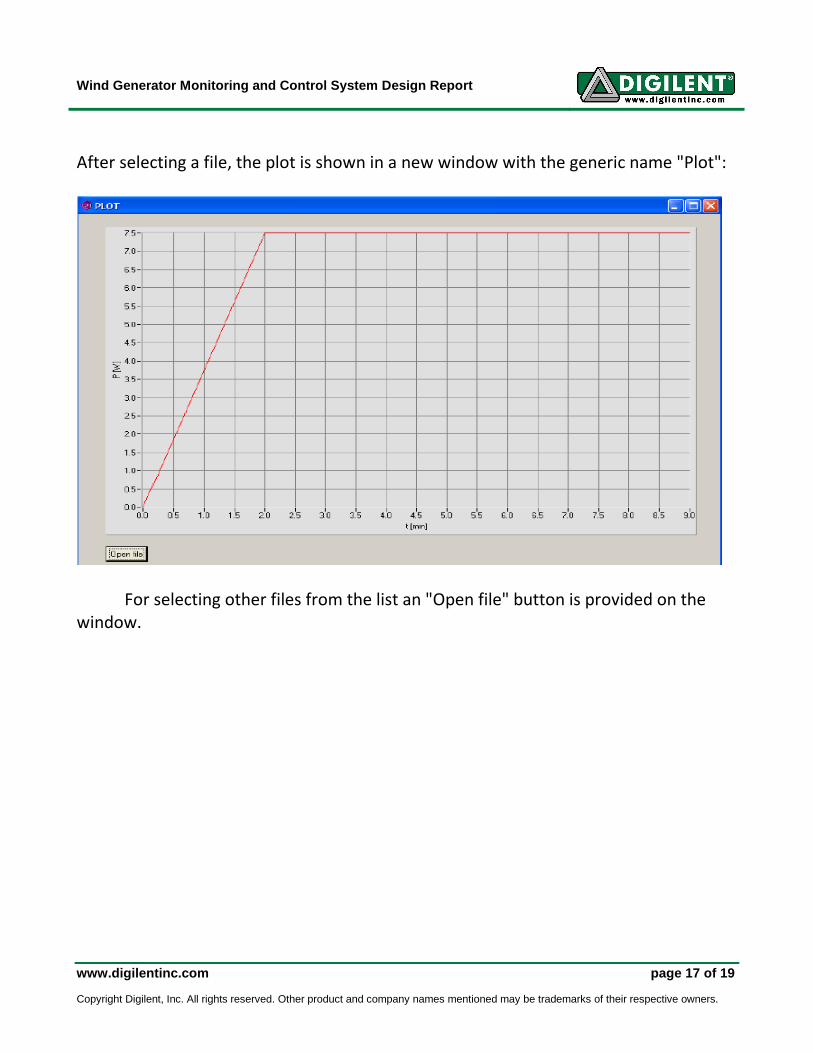
After selecting a file, the plot is shown in a new window with the generic name "Plot":
For selecting other files from the list an "Open file" button is provided on the
window.

Wind Generator Monitoring and Control System Design Report
www.digilentinc.com page 18 of 19 Copyright Digilent, Inc. All rights reserved. Other product and company names mentioned may be trademarks of their respective owners.
References
(1) Electronică de putere - Doru Suciu (2) Dispozitive electronice si electronica analogica Lucrări de laborator (UPM)- GERMÁN-SALLÓ Zoltán
(3) Sisteme cu microprocesoare. Îndrumător de laborator (UPM) - Duka Adrian, Jovrea Titus
(4) Programarea interfeţelor îm LabWindows. Îndrumător de laborator (UPM) - Haller Piroska, Duka Adrian Vasile, Rusu Marius Sebastian
(5) Wind Energy Handbook -Tony Burton, David Sharpe, Nick Jenkins, Ervin Bossany
(6) http:// www.hobbielectronika.hu

Wind Generator Monitoring and Control System Design Report
www.digilentinc.com page 19 of 19 Copyright Digilent, Inc. All rights reserved. Other product and company names mentioned may be trademarks of their respective owners.
Appendix A:
• Source code files : - monitoring station: CCMTE_RadioPC.c - wind generator system: CCMTE_Radio_T.c
• CVI application: CCMTE_CVI - CCMTE_CVI.001 - CCMTE_CVI.002 - CCMTE_CVI.exe - setup