wind farm noises: mechanisms and evidence for their...
TRANSCRIPT

1
Wind farm noises: Mechanisms and evidence for their 1
dependency on wind direction 2
Nima Sedaghatizadeh*, Maziar Arjomandi, Benjamin Cazzolato and Richard 3
Kelso 4
School of Mechanical Engineering, the University of Adelaide, SA 5000, Australia 5
*Corresponding author. E-mail: [email protected] 6
Abstract. The mechanisms responsible for swishing and thumping noises generated by wind 7
turbines are unclear and the existence of which have significantly affected the perception of 8
wind energy by the community. To better understand the nature of this noise source, this study, 9
for the first time, investigates the correlation between the potential noise generation mechanisms 10
in wind farms and the characteristics of the perceived noise reported by residents in the vicinity 11
of the farms in survey data. Published reports and measurements show that in addition to the 12
perceived noise near the turbines, the thumping noise, in general, is perceived far downstream 13
of the turbines. Normal swish perceived in a short distance from a wind turbine, especially in 14
the cross-wind directions, can be explained by the convective amplification and directivity of 15
the trailing edge noise. As will be discussed in this article, there exists strong evidence that the 16
dominant mechanism of wind farm noise is associated with amplitude modulation of the 17
aerodynamic noise by the eddies generated when the turbine blade partially stalls or due to an 18
interaction with the turbine wake. This hypothesis is primarily based on the low frequency 19
characteristics of the stall and also the distance and direction of the noise propagation. Moreover, 20
it is hypothesised that the wake supplements this effect as it results in refraction and modulation 21
of the emitted noise. 22
Keyword: noise perception, wind turbine noise, amplitude modulation, stall noise, trailing edge noise, 23
low frequency noise 24
1. Introduction 25
Wind energy has had the fastest growth rate among the renewable sources of energy over the past few 26
decades due to its competitive price and mature technology. This has resulted in the widespread 27
deployment of wind turbines in rural communities, which, despite resulting in some economic and 28
environmental benefits, has led to negative community impact, such as health concerns, which in turn, 29
are hypothesised to be related to the wind turbine noise [1-5]. 30
Wind turbine noise can be categorised into two groups [6-9]: a) mechanical noise, which is well studied 31
and understood, can be easily mitigated and can usually be perceived only in the vicinity of a turbine 32

2
[10]; b) aeroacoustic or aerodynamic noise which is generated due to fluctuating forces interacting with 33
the blades of the wind turbines. There exist several mechanisms contributing to the generation of 34
aerodynamic noise from a wind turbine such as: turbulent inflow, turbine blade stall, blade trailing edge, 35
blade-tower interaction, blade tip and laminar boundary layer vortex shedding [11]. The last two 36
mechanisms are predominantly high frequency signatures and are unlikely to play significant roles in 37
perceived noise far from the wind turbines. While blade-tower interaction has been reported as a major 38
noise source for downwind turbines due to interaction of the blade and vortex shedding from the tower, 39
studies show that the effect of perturbed flow upstream of the towers of modern upwind turbines is not 40
significant in generation of unsteady loads on the blade compared to the load variation due to interaction 41
of the blade with the incoming turbulence [12]. Moreover, the level of noise generated by the blade-42
tower interaction also decreases as the mean wind speed and yaw error increase, while the level of noise 43
generated by other mechanisms increases under these conditions [12, 13]. In addition, the noise 44
generated due to the blade-tower interaction occurs at the blade pass frequency and may contribute to 45
the infrasound (frequency less than 16 Hz) [14, 15], hence it is not the objective of this study which 46
investigates only the audible sound. 47
To explain the mechanisms which are believed to be the main sources of the noise generated by wind 48
turbine blades, a schematic of the flow over a blade is shown in Figure 1. When the blade encounters 49
turbulence eddies from incoming flow, fluctuating forces on the blade surface result in noise generation. 50
The frequency of the emitted noise has an inverse relationship with the size of the incoming eddies such 51
that the larger eddies generate noise at lower frequencies compared with the noise generated due to 52
interaction of the blade with smaller eddies [16, 17]. Trailing edge noise is generated by the eddies in 53
the scale of boundary layer displacement thickness at the trailing edge of the airfoil, which results in 54
fluctuating forces at a moderate frequency (400-1000 Hz) [7, 11]. Stall and consequent vortices 55
generated due to the flow separation also result in fluctuating load on the airfoil and if the deep stall 56
occurs large eddies will form on the suction of the airfoil which result in a significant increase in noise 57
level at an audible lower range of frequency (100-400 Hz) [11, 18]. 58

3
59
Amplitude modulation is also another mechanism, which affects the emitted noise from wind farms and 60
has been reported to be one of the reasons of perceived annoying noise [11, 19]. Amplitude modulation 61
is characterised by a variation of the level and character of noise in time. The normal amplitude 62
modulation is caused due to variation in noise level due to movement of the source of the trailing edge 63
noise during the rotation of the blade. Normal amplitude modulation of broadband trailing edge noise 64
occurs at blade pass frequency with the fluctuation of a few decibels and is perceived in close distance 65
of wind turbines [11]. There exists another type of amplitude modulation, so called Other Amplitude 66
Modulation (OAM) or Enhanced Amplitude Modulation (EAM), which has stronger low-frequency 67
content and increased depth of the modulation (6-12 dB) [11, 20]. EAM can be caused by the partial or 68
transient stall on the blade when the blade interacts with incoming eddies, turbine wake or inclined 69
flow. Since most of the survey data are collected far downstream of the turbines it can be concluded 70
that EAM or OAM can be the underlying mechanism for perceived noise. As will be discussed further 71
in the text and in section 3, 72
Two main features of the aerodynamic noise are noticeable: a) “swish” which has broadband content 73
and directed towards the leading edge, generated primarily due to turbulent boundary layer interaction 74
with the trailing edge of the turbine airfoil; b) “thumping” at the blade pass frequency which travels a 75
few kilometres and is known to have the most annoying effect on people [9, 21-24]. This article 76
investigates the above sources of noise with a focus on thumping as explained above. 77
In the past decades a large number of scientific articles have been published on the mechanisms of noise 78
generation from wind turbines with the main focus on reporting the outcomes of laboratory experiments 79
and numerical modelling [11, 25-29]. In contrast to the published literature, this article for the first time 80
is based on the statistical analysis of the recorded complaints by the residences in the vicinity of wind 81
Wind
Incoming turbulence
Boundary layer on
the blade
Eddies in the turbulent boundary
layer, which generate noise at a
moderate frequency range (400-
1000 Hz) due to interaction with
trailing edge.
Separated boundary layer,
with shear layer eddies
interacting with the blade
surface which generate low-
frequency noise.
Figure 1 Incoming flow features and different noise generation mechanisms.

4
farms. This has been done in an attempt to draw a correlation between the sound directivity, the 82
prevailing wind direction and the blade angle of attack. In this paper, a meta-data analysis has been 83
conducted based on the reported noise perception surveys combined with the publically available 84
information on the directivity of the airfoil noise at different pitch angles. This approach is used in order 85
to provide a quantitative support for the hypothesised underlying physical mechanisms for noise 86
generation. This can contribute significantly to the field, since the outcomes of this work can be used 87
by wind farm designers and decision makers to identify the source of the noise observed at residences, 88
which potentially can be used in the design of future wind farms. In the following section, the main 89
mechanisms for airfoil noise are described and the survey data from the residents in the vicinity of four 90
wind farms are analysed to establish a relationship between the perceived noise and the associated 91
mechanisms. A data analysis approach is utilised in the next section to determine the dominant 92
underlying mechanism for wind turbine noise. This section is followed by a discussion and summary 93
of the outcomes from the statistical analysis of the survey data to conclude the possible noise generation 94
mechanism. 95
2. Directivity of the perceived noise 96
Figure 2a shows a typical wind turbine. The turbine blade is generally twisted such that the airfoil 97
reaches its maximum pre-stall angle of attack along its span when it rotates at its nominal rotational 98
speed [30, 31]. The directivity of the trailing edge and stall noise is shown at three segments of the blade 99
in Figure 2b. As shown on Figure 2b, the trailing edge noise is largest along the airfoil chordline and 100
towards the leading edge, which means it tends to be perceived at the locations approximately 101
perpendicular to the relative wind direction [17, 32]. Due to higher attenuation rate of the high frequency 102
trailing edge noise, the direction of the highest sound level is considered in this study as the main 103
direction of propagation of trailing edge noise. In contrast, the noise perceived downstream of the wind 104
turbine and parallel to the wind direction is unlikely to be associated with the trailing edge. Hence, the 105
source of the perceived noise is hypothesised to be related to the blade operation at stall [11, 18] and 106
near stall [9, 21, 26]. Stall conditions on the blade can result from sudden changes of the angle of attack 107
due to interaction with the inclined and turbulence inflow arising from the topographic roughness or 108
tandem positioning of the turbines [13, 33, 34]. Length scale of the incoming turbulences also has a 109
significant effect on the pressure fluctuation on the blade, as well as the local angle of attack of the 110
airfoil and hence, it can significantly change the noise emission. The length scale of the eddies is 111
partially associated with the topography and roughness of the terrain, as well as the height and the 112
location of the turbine. In complex terrains, these eddies in addition to the acceleration and deceleration 113
of the flow, change the local angle of attack on some parts of the turbine blade, resulting in partial or 114
transient stall. Moreover, partial and transient stall of the blade can result in amplitude modulation of 115

5
the noise which can be perceived as thumping noise downstream of the wind turbine with up to 6 to 10 116
dB modulation depth [11, 19]. This will be further discussed in the following sections. 117
118
Four sites have been studied in an attempt to correlate the noise directivity and wind direction with the 119
reported complaints from residents in the areas surrounding wind farms. The four sites of Makara (New 120
Zealand), Waterloo (Australia), Bears Down (United Kingdom) and Te Rere Hau (New Zealand) were 121
chosen as the residences in the vicinity of these farms were formally surveyed and the results have been 122
published in peer reviewed articles [6, 7, 35, 36]. The direction of the wind and the perception of noise 123
have been assessed based on the reported residents’ surveys, in addition to the associated wind 124
conditions using meteorological databases. An investigation has been carried out to correlate the wind 125
directions with the largest number of complaints. Then the correlation between different sources of 126
noise and their characteristics at the perceived locations were used to understand the mechanisms 127
responsible for the greatest number of complaints. 128
Figure 2 a) Schematic of wind turbine and orientation of blade due to twist (𝜽𝒓 is the blade twist angle at the root and 𝜽𝒕 is the blade twist angle at the tip), b) Directivity of trailing edge noise (solid line) and stall or turbulent inflow noise (dotted
line).
Location of noise
perception
Wind
direction 10% of the span 50% of the span 90% of the span
90% of the span
50% of the span
10% of the span
Twist along the
blade length
Plane of rotation of the turbine
b)
a)
𝜃𝑟
Zero twist
𝜃𝑡

6
2.1.Site 1 129
Waterloo Wind Farm located in South Australia, comprises thirty seven Vestas V90/3000 wind 130
turbines, mounted on 80-metre towers, providing a generating capacity of 111 MW. The turbines rotate 131
clockwise and are placed on a low ridge in a relatively flat terrain. 132
133
Since the beginning of the wind farm’s operation, a significant number of complaints about the turbines 134
noise have been received from local residents. The South Australian Environment Protection Authority 135
(EPA) conducted an investigation on noise perception by residents at six locations around this wind 136
farm [35]. Figure 3 illustrates the wind-rose during the investigation period and results of completed 137
surveys about wind farm noise for different locations, showing the dominant wind direction at the time 138
when complaints were registered. Hereafter, the green circle will be used to indicate the noise perception 139
location and the blue triangles represent the wind turbines. Each green circle represents the central 140
location of different groups of residences that completed the noise survey. It should be noted that most 141
of the complaints were received from residents in location 2, 3, 4 and 5 and the results are presented as 142
percentage of the dominant wind direction to the total number of complaints for each location. Data 143
were selected from the surveys completed for a week which the wind blew in all directions and residents 144
Figure 3 a) Site map of Waterloo Wind Farm showing the dominant wind directions associated with highest occurrence of
noise perception in different locations (bigger arrows show the higher percentage of complaints at the associated location).
Triangles represent turbine locations and the percentage of the complaints associated with each direction is represented next
to each arrow. It should be noted that the remaining directions are attributed to less than 5% of complaints for each location,
b) Wind-rose during the period of the noise study. The wind velocity at hub height was in the range of 6-9.2 m/s at the time
of noise perception.
(a)
6
5
3
2
4
1
2a
2b3a
3b
4a
4b
5b
5a
a b(b)
22%
25%
16%
16%
37.5%
49%
21%
15%
21%
7
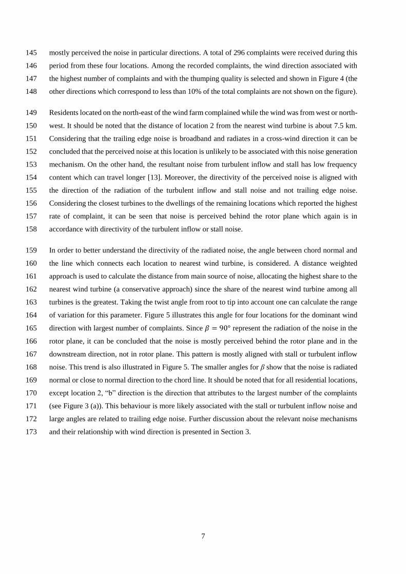
mostly perceived the noise in particular directions. A total of 296 complaints were received during this 145
period from these four locations. Among the recorded complaints, the wind direction associated with 146
the highest number of complaints and with the thumping quality is selected and shown in Figure 4 (the 147
other directions which correspond to less than 10% of the total complaints are not shown on the figure). 148
Residents located on the north-east of the wind farm complained while the wind was from west or north-149
west. It should be noted that the distance of location 2 from the nearest wind turbine is about 7.5 km. 150
Considering that the trailing edge noise is broadband and radiates in a cross-wind direction it can be 151
concluded that the perceived noise at this location is unlikely to be associated with this noise generation 152
mechanism. On the other hand, the resultant noise from turbulent inflow and stall has low frequency 153
content which can travel longer [13]. Moreover, the directivity of the perceived noise is aligned with 154
the direction of the radiation of the turbulent inflow and stall noise and not trailing edge noise. 155
Considering the closest turbines to the dwellings of the remaining locations which reported the highest 156
rate of complaint, it can be seen that noise is perceived behind the rotor plane which again is in 157
accordance with directivity of the turbulent inflow or stall noise. 158
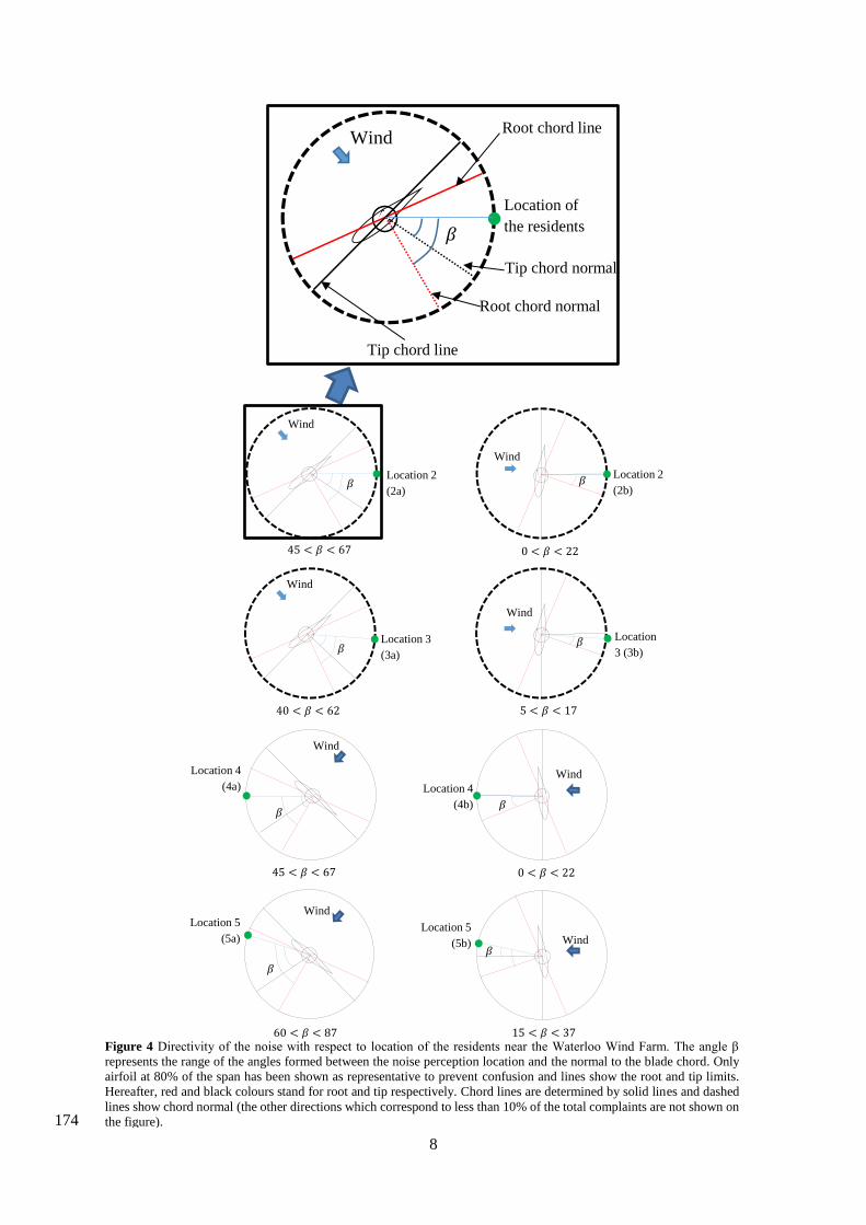
In order to better understand the directivity of the radiated noise, the angle between chord normal and 159
the line which connects each location to nearest wind turbine, is considered. A distance weighted 160
approach is used to calculate the distance from main source of noise, allocating the highest share to the 161
nearest wind turbine (a conservative approach) since the share of the nearest wind turbine among all 162
turbines is the greatest. Taking the twist angle from root to tip into account one can calculate the range 163
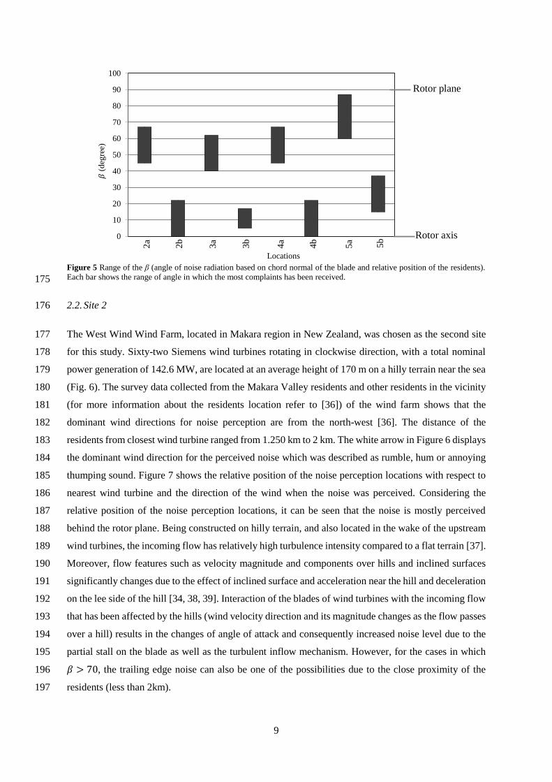
of variation for this parameter. Figure 5 illustrates this angle for four locations for the dominant wind 164
direction with largest number of complaints. Since 𝛽 = 90° represent the radiation of the noise in the 165
rotor plane, it can be concluded that the noise is mostly perceived behind the rotor plane and in the 166
downstream direction, not in rotor plane. This pattern is mostly aligned with stall or turbulent inflow 167
noise. This trend is also illustrated in Figure 5. The smaller angles for β show that the noise is radiated 168
normal or close to normal direction to the chord line. It should be noted that for all residential locations, 169
except location 2, “b” direction is the direction that attributes to the largest number of the complaints 170
(see Figure 3 (a)). This behaviour is more likely associated with the stall or turbulent inflow noise and 171
large angles are related to trailing edge noise. Further discussion about the relevant noise mechanisms 172
and their relationship with wind direction is presented in Section 3. 173
8
174
Location 2
(2a)
Wind
𝛽
𝛽
Wind
0 𝛽
𝛽Location 2
(2b)
Wind
𝛽
𝛽 Location
3 (3b)
Location 3
(3a)
Wind
𝛽
0 𝛽
Location 4
(4a)
Wind
𝛽
𝛽
Wind
0 𝛽
𝛽
Location 4
(4b)
Location 5
(5a)
Wind
𝛽
0 𝛽
Wind
𝛽
Location 5
(5b)𝛽
Figure 4 Directivity of the noise with respect to location of the residents near the Waterloo Wind Farm. The angle β
represents the range of the angles formed between the noise perception location and the normal to the blade chord. Only
airfoil at 80% of the span has been shown as representative to prevent confusion and lines show the root and tip limits.
Hereafter, red and black colours stand for root and tip respectively. Chord lines are determined by solid lines and dashed
lines show chord normal (the other directions which correspond to less than 10% of the total complaints are not shown on
the figure).
Section 2
(2a)
Wind
𝛽
𝛽
Wind
0 𝛽
𝛽Section 2
(2b)
Wind
𝛽
𝛽 Section 3
(3b)
Section 3
(3a)
Wind
𝛽
0 𝛽
Section 4
(4a)
Wind
𝛽
𝛽
Wind
0 𝛽
𝛽
Section 4
(4b)
Section 5
(5a)
Wind
𝛽
0 𝛽
Wind
𝛽
Section 5
(5b)𝛽
Tip chord normal
Root chord line
Tip chord line
Root chord normal
Location of
the residents
9
175
2.2. Site 2 176
The West Wind Wind Farm, located in Makara region in New Zealand, was chosen as the second site 177
for this study. Sixty-two Siemens wind turbines rotating in clockwise direction, with a total nominal 178
power generation of 142.6 MW, are located at an average height of 170 m on a hilly terrain near the sea 179
(Fig. 6). The survey data collected from the Makara Valley residents and other residents in the vicinity 180
(for more information about the residents location refer to [36]) of the wind farm shows that the 181
dominant wind directions for noise perception are from the north-west [36]. The distance of the 182
residents from closest wind turbine ranged from 1.250 km to 2 km. The white arrow in Figure 6 displays 183
the dominant wind direction for the perceived noise which was described as rumble, hum or annoying 184
thumping sound. Figure 7 shows the relative position of the noise perception locations with respect to 185
nearest wind turbine and the direction of the wind when the noise was perceived. Considering the 186
relative position of the noise perception locations, it can be seen that the noise is mostly perceived 187
behind the rotor plane. Being constructed on hilly terrain, and also located in the wake of the upstream 188
wind turbines, the incoming flow has relatively high turbulence intensity compared to a flat terrain [37]. 189
Moreover, flow features such as velocity magnitude and components over hills and inclined surfaces 190
significantly changes due to the effect of inclined surface and acceleration near the hill and deceleration 191
on the lee side of the hill [34, 38, 39]. Interaction of the blades of wind turbines with the incoming flow 192
that has been affected by the hills (wind velocity direction and its magnitude changes as the flow passes 193
over a hill) results in the changes of angle of attack and consequently increased noise level due to the 194
partial stall on the blade as well as the turbulent inflow mechanism. However, for the cases in which 195
𝛽 > 0, the trailing edge noise can also be one of the possibilities due to the close proximity of the 196
residents (less than 2km). 197
𝛽 (
deg
ree)
Figure 5 Range of the β (angle of noise radiation based on chord normal of the blade and relative position of the residents).
Each bar shows the range of angle in which the most complaints has been received.
Locations
0
10
20
30
40
50
60
70
80
90
100
2a
2b
3a
3b
5a 5b
4b
4a
Sections
(deg
ree)
Rotor plane
Rotor axis

10
198
199
2.3. Site 3: 200
Site 3 is the Bears Down Wind Farm located in Cornwall area in England (see Figure 8). The site 201
consists of sixteen 0.6 MW Bonus wind turbines providing 9.6 MW in total, located in an almost flat 202
area. In this study consideration was made of the nearest residents influenced by the wind farm noise 203
and their reports [6]. The distance of the dwellings in this area from nearest wind turbine is 204
approximately 1.1km. 205
Figure 6 Aerial photograph of the location of the West Wind Wind Farm and the residents of Makara and dominant wind
directions. Triangles represent the turbine locations. The arrow shows the wind direction associated with the highest
percentage of complaints.
Relative position of the
residents with respect
to nearest wind turbine
Wind
𝛽
𝛽
Figure 7 Directivity of the noise with respect to relative location of the residents in West Wind Wind Farm.

11
206
As can be seen in Figure 8, most of the complaints were claimed for wind directions from south to 207
south-westerly. Reports reveal that 73% of the “swish” or “whoosh” noise perception occurred for the 208
small arc from southerly to south-westerly [7]. Figure 9 shows the directivity of the perceived noise 209
with respect to relative position of the residents. As can be seen the noise is perceived mostly in rotor 210
plane or slightly in upwind direction aligned with chord line. Considering the proximity and direction 211
of propagation, it can be concluded that the trailing edge noise is the underlying noise generation 212
mechanism in this case. 213
214
2.4.Site 4 215
Figure 10 shows the Te Rere Hau Wind Farm in New Zealand, consisting of ninety-seven two-bladed 216
Windflow 500 turbines, generating a total power output of 48.5 MW. The turbines rotate clockwise and 217
are located on relatively hilly ground. Results gathered from residents’ diaries around the wind farm 218
show that thumping and pulsing noise was perceived for the easterly and south-easterly winds [36]. 219
For the easterly wind direction, the noise perception occurred in the location behind the rotor plane of 220
most of the working turbines. Located in a hilly environment in a relatively dense cluster, the blades of 221
Figure 8 Aerial photograph of the Bears Down Wind Farm showing the location of residents (googlemap.com). Triangles
represent wind turbines and arrows show the wind direction associated with noise perception.
b a
Wind
𝛽
𝛽
Relative position of the
residents with respect to
nearest wind turbine
Wind
𝛽
0 𝛽
TCL
Figure 9 Directivity of the noise with respect to relative location of the residents in Bears Down Wind Farm. a) Southerly
wind direction, b) South-Westerly wind direction.
(a) (b)
12
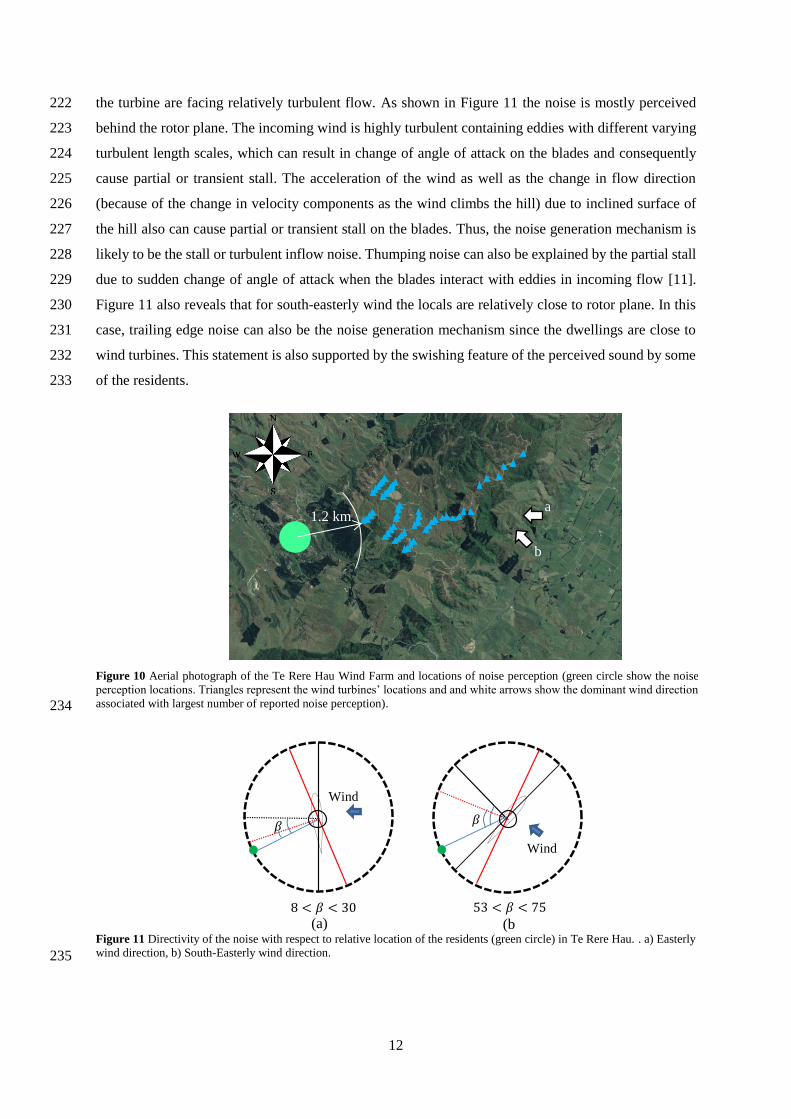
the turbine are facing relatively turbulent flow. As shown in Figure 11 the noise is mostly perceived 222
behind the rotor plane. The incoming wind is highly turbulent containing eddies with different varying 223
turbulent length scales, which can result in change of angle of attack on the blades and consequently 224
cause partial or transient stall. The acceleration of the wind as well as the change in flow direction 225
(because of the change in velocity components as the wind climbs the hill) due to inclined surface of 226
the hill also can cause partial or transient stall on the blades. Thus, the noise generation mechanism is 227
likely to be the stall or turbulent inflow noise. Thumping noise can also be explained by the partial stall 228
due to sudden change of angle of attack when the blades interact with eddies in incoming flow [11]. 229
Figure 11 also reveals that for south-easterly wind the locals are relatively close to rotor plane. In this 230
case, trailing edge noise can also be the noise generation mechanism since the dwellings are close to 231
wind turbines. This statement is also supported by the swishing feature of the perceived sound by some 232
of the residents. 233
234
235
Figure 10 Aerial photograph of the Te Rere Hau Wind Farm and locations of noise perception (green circle show the noise
perception locations. Triangles represent the wind turbines’ locations and and white arrows show the dominant wind direction
associated with largest number of reported noise perception).
1.2 km a
b
Wind
𝛽 0
𝛽
Wind
𝛽
𝛽
Figure 11 Directivity of the noise with respect to relative location of the residents (green circle) in Te Rere Hau. . a) Easterly
wind direction, b) South-Easterly wind direction.
(a) (b
)

13
3. Summary and discussion on the underlying mechanism 236
As previously described in Section 1, each aerodynamic noise mechanism has charecterisics which can 237
be used to differntiate from one another. Based on the experimental study conducted by Oerlemans 238
[11], the trailing edge noise has higher sound level at the outer part of the blade during its descent (see 239
Figure 12). Thus in all analysis the foil orientation at 80% of the span is used for directivity analysis. 240
As shown in Figure 2, the trailing edge noise is strongest towards the leading edge. Hence it is expected 241
to be better perceived in rotor plane or crosswind direction. On the other hand, stall or turbulent inflow 242
noise are stronger normal to the chordline of the airfoil. Considering the orientation of the airfoil this 243
noise is likely to be perceived behind the rotor plane. The frequency content of these noise sources are 244
also different, with trailing edge noise containing higher frequency content which attenuates faster 245
compared to stall and turbulent inflow noise. Moreover, measurements and qualitative descriptions of 246
the noise at residents downstream of the wind turbine show evidences of an enhanced amplitude 247
modulation different from normal amplitude modulation (which is perceived in a cross-wind direction 248
due to rotation of the blades). This phenomenon can be explained by amplitude modulation due to 249
partial stall which is supported by the directivity characteristics of the stall noise and its lower dominant 250
frequency content when compared to normal amplitude modulation. 251
252
Figure 13 shows the directivity angle (β) of the perceived noise with regard to chord line normal. Larger 253
angles mean that the noise perception locations are close to rotor plane, and due to close proximity to 254
wind turbines for this case it can be concluded that the perceived noise is broadband trailing edge noise. 255
However, for the cases with small angles, residents are close to the normal plane, and considering the 256
large distance from wind turbine, it can be concluded that the turbulent inflow or stall noise is the 257
underlying mechanism. The presented evidence shows that the dominant direction for noise radiation 258
Figure 12 Noise emission from a large wind turbine in the rotor plane, measured by microphone arrays at 1D upstream of
the turbine. As seen, the noise is mostly produced at the outer part of the blade during its descent [32].

14
is downstream of the wind turbine, which is in agreement with the study conducted by Cooper et al. 259
[40]. The dominance of the downstream direction becomes more distinct as the distance from wind 260
turbines increases. The swish noise generated by trailing-edge noise, mostly includes high-frequency 261
signatures and radiates in the cross-wind direction. Noise perception and measurements at large 262
distances downstream of the wind farms suggest that directly propagated trailing edge noise is not the 263
underlying mechanism of the disturbing noise. 264
265
To explain the underlying mechanism of emitted aerodynamic noise, the flow interaction with blade 266
should be considered. Flow characteristics over rotor blades significantly affects the aeroacoustic noise 267
emitted from the wind turbines. Madsen et al. [26] investigated the noise radiated from the blade of a 268
NM80 turbine for various angles of attack. Figure 14 shows the acoustic power spectral densities for a 269
segment of the blade at angles of attack from ° to °. The low-frequency noise (LFN, i.e., 𝑓 270
00 Hz) levels suddenly increases when the angle of attack (AoA) changes from 12 to 13 degrees, 271
which is the onset of stall on the blade. It is hypothesised that this increase could be the main contributor 272
for periods of reported increased swish and thumping sound in far field, which is also denoted as 273
enhanced amplitude modulation (EAM) in literatures [11]. 274
0
10
20
30
40
50
60
70
80
90
100
Wat
erlo
o-2
a
Wat
erlo
o-2
b
Wat
erlo
o-3
a
Wat
erlo
o-3
b
Wat
erlo
o-5
a
Wat
erlo
o-5
b
Wat
erlo
o-4
b
Wat
erlo
o-4
a
Wes
t W
ind
Bea
rs D
ow
n-a
Bea
rs D
ow
n-b
Te
Rer
e H
au-a
Te
Rer
e H
au-b
The
zon
ew
ith
the
larg
est
nu
mb
ero
fco
mp
lain
tsin
the
dis
tance
gre
ater
than
2.5
km
The
zone
wit
h t
he
larg
est
num
ber
of
com
pla
ints
in
the
dis
tance
les
than
2.5
km
(deg
ree)
SectionsFigure 13 Summary of the directivity angle (β) of the noise with respect to relative location of the noise perception. In this
figure the closest wind turbine is identified by the shortest straight line connecting the wind turbine to the location of the
residents.
Locations
β (
deg
ree)

15
275
High shear in the atmospheric boundary layer, turbulent vortices due to the ground topography and 276
working in the wake of an upstream turbine, can result in changes to the angle of attack and 277
consequently stall the blades of a turbines. Studies show that stall can occur on more than 30% of the 278
blade of the downstream turbine even with 15 diameters separation [33]. Tip vortices and vortical 279
structures can suddenly change the angle of attack at the outer parts of the blades, causing partial stall 280
and increased noise level near the blade tips. Partial stall on the turbine’s blade due to incoming 281
turbulences, inclined flow, gusts and wind shear generates amplitude modulation of the sound signature 282
in the far field. 283
Aerodynamic noise emission from wind turbines is a complicated phenomenon, compounded by the 284
movement of the noise source and the effect of the flow on noise radiation. Variations of the velocity 285
in the atmospheric boundary layer and ground reflection also affect the noise propagation. 286
The flow over the blades of wind turbines is complex, containing turbulent structures due to the wakes 287
of other wind turbines or turbulence in atmosphere [41]. Bound vortices, ring of tip vortices and other 288
vortical structures in the wake region can affect the noise propagation from blades. Colonius et al. [42] 289
investigated the effect of a single vortex on noise propagation. They found that it has significant effect 290
on directivity of a planar sound wave. This type of behaviour would be expected to occur for sound 291
generated by turbine blades. Rotating blades also exert centrifugal forces on the flow over the blade 292
surfaces, causing the flow to move toward the tip of the blade. This phenomenon also affects the noise 293
propagation and noise emission from blades [42, 43]. 294
Figure 16 shows the wake vortex structure system behind a wind turbine. Tip vortices are generated at 295
the tip of the blade due to pressure difference between the suction and pressure side of the blade. 296
Rotation of the blade results in the formation of the helical structures when the tip vortices propagate 297
102 103 104
120
115
110
105
100
95
90
85
80
Spp
(dB
)
Centre frequency (Hz)Figure 14 Effect of AoA on narrow band spectra of surface pressure [19] (permission has been obtained to use this figure).
Spp (
dB
)
Centre frequency (Hz)

16
downstream with the flow. Emitted noise from the blade enters the wake region, which is surrounded, 298
by helical tip vortices. Studies show that the wake of a wind turbine acts like a duct for the sound waves 299
enter in this region and results in refraction of the sound signals [44]. Barlas et al. [44] used parabolic 300
equation method to study the effect of wake and velocity deficit in the wake region on the noise 301
propagation. They found that wake acts like a duct for noise source on the blade and constrains the 302
acoustic energy and affects its directivity. Their results show the considerable effect of the wake on the 303
noise level in the far field when compared with no-wake condition such that the far field noise level can 304
be increased by 7.5 dB at the wake centre in a stable atmospheric boundary layer. Moreover, interaction 305
of the sound waves with the wavelength in the same order of the vortices, results in refraction of the 306
sound towards the downstream direction [42]. Nevertheless, the effect of vortices in the wake region on 307
noise propagation has not been fully understood yet, due to the complexity of the flow and turbulent 308
structures in this region. 309
310
4. Conclusion 311
Noise propagation from wind farms depends on source directivity, geometric spreading and 312
atmospheric absorption, ground reflections and absorption, meteorological effects such as refraction 313
and convection, terrain complexity and wind direction. According to extant literature, the dominant 314
source of noise is the railing edge noise, which occurs on the outer part of the blade. This sound radiates 315
Vortex shedding
from tower
Tip vortices
Wind
direction
Bound vortices
Central vortex
Figure 16 Schematic diagram of the typical vortex system downstream of a wind turbine. In addition to tip, bound and root
vortices, vortical structures and turbulences in the wake region and velocity deficit can result in refraction of the generated
noise from turbine blades.
Direction of
rotation Interference of the
tower

17
toward the observer in the rotor plane and it is strongest towards the leading edge. Trailing edge noise 316
directivity and its varying location due to blade rotation, results in a specific type of amplitude 317
modulation referred to as normal amplitude modulation, heard as a swish sound in the cross-wind 318
direction. However, analysing the noise perception data from the residents in the vicinity of several 319
wind farms revealed that noise is mostly perceived in downwind locations. The evidence also revealed 320
the existence of amplitude modulation far from the wind turbines. 321
Based on the direction and the distance of noise propagation, and its swish and thumping characteristics, 322
it is concluded that the increased noise levels far downstream of the wind turbines is caused by stall or 323
turbulent inflow mechanisms. Transient or partial stall on the blade is caused by sudden changes in the 324
angle of attack due to incoming turbulence, strong wind shear, sudden gusts, tripped oncoming flow 325
and yaw misalignment. In stable conditions with a relatively flat ground surface, the incoming 326
turbulence and non-uniform flow due to the wakes of other turbines could be the reason for local stall 327
and turbulent-induced noise. Local stall and turbulent-inflow noise have lower frequencies compared 328
with trailing edge noise and can travel greater distances downwind. Interaction of sound waves with 329
helical tip vortices and other vortical structures in the wake region results in higher noise perception in 330
the wake-affected zone and its vicinity. Moreover, the wake acts as a conduit directing the noise energy 331
downstream up to up to the point of the breakdown of the wake vortex resulting in higher noise level at 332
the wake centre and in far-field region. This effect is supplemented with amplitude modulation by the 333
cyclic augmentation in noise level due to partial stall. Based on the directivity pattern of the 334
aerodynamic noise mechanism, it can be concluded that the stall noise ducted by the wake results in 335
higher noise level at the break-down point. This mechanism explains the measured and perceived 336
increase in noise in locations far behind wind turbines. 337
338
339
340
341
342
343
344

18
References 345
[1] J. Sawin, Renewables 2014: Global Status Report, in: Report Published by Renewable Energy Policy Network 346
for the 21st Century, 2014. 347
[2] B. Nobbs, C.J. Doolan, D.J. Moreau, Characterisation of Noise in Homes Affected by Wind Turbine Noise, 348
in: Acoustics 2012 - Fremantle, Fremantle, Australia, 2012. 349
[3] R.H. Bakker, E. Pedersen, G.P.V.d. Berg, R.E. Stewart, W. Lok, J. Bouma, Impact of Wind Turbine Sound 350
on Annoyance, Self-Reported Sleep Disturbance and Psychological Distress, Science of the Total Environment, 351
425 (2012) 42-51. 352
[4] M. Meunier, Wind Farm - Long Term Noise And Vibration Measurements, in: ICA 2013 Montreal, Acoustical 353
Society of America through the American Institute of Physics, Montreal, Canada, 2013. 354
[5] A. Crespo, J. Hernández, S. Frandsen, Survey of modelling methods for wind turbine wakes and wind farms, 355
Wind Energy, 2 (1999) 1-24. 356
[6] J. Stewart, Location, Location, Location, an Investigation into Wind Farms and Noise by the Noise 357
Association, in: Reoprt published by the Noise Association, London, 2002. 358
[7] A. Moorhouse, M. Hayes, Sabine von Hünerbein, B. Piper, M. Adams, Research into Aerodynamic 359
Modulation of Wind Turbine Noise: Final Report, 2007. 360
[8] J.M. Ellenbogen, S. Grace, W.J. Heiger-Bernays, J.F. Manwell, D.A. Mills, K.A. Sullivan, M.G. Weisskopf, 361
S.L. Santos, Wind Turbine Health Impact Study: Report of Independent Expert Panel, in, Massachusetts 362
Department of Environmental Protection, Massachusetts Department of Public Health, 2012. 363
[9] S. Oerlemans, J.G. Schepers, Prediction of Wind Turbine Noise and Validation Against Experiment, in: Repert 364
published by National Aerospace Laboratory NLR, 2009. 365
[10] V. Katinas, M. Marčiukaitis, M. Tamašauskienė, Analysis of the Wind Turbine Noise Emissions and Impact 366
on the Environment, Renewable and Sustainable Energy Reviews, 58 (2016) 825-831. 367
[11] S. Oerlemans, An Explanation for Enhanced Amplitude Modulation of Wind Turbine Noise, in: Report 368
Published by National Aerospace Laboratory NLR, 2011. 369
[12] H. Kim, S. Lee, S. Lee, Influence of Blade-Tower Interaction in Upwind-Type Horizontal Axis Wind 370
Turbines on Aerodynamics, Journal of Mechanical Science and Technology, 25 (2011) 1351-1360. 371
[13] A. Laratro, M. Arjomandi, R. Kelso, B. Cazzolato, A Discussion of Wind Turbine Interaction and Stall 372
Contributions to Wind Farm Noise, Journal of Wind Engineering and Industrial Aerodynamics, 127 (2014) 1-10. 373
[14] N.S. Timmerman, Wind Turbine Noise, Acoustics Today, 9 (2013) 22-29. 374
[15] V.V. Lenchine, J. Song, Infrasound and Blade Pass Frequency Levels in Areas adjacent to Wind Farms, in: 375
INTER-NOISE 2014, Melbourne, Australia, 2014. 376
[16] F.V.d. Berg, The Beat Is Getting Stronger: The Effect of Atmospheric Stability on Low Frequency Modulated 377
Sound of Wind Turbines, Journal of Low Frequency Noise, Vibration & Active Control, 24 (2005) 1-24. 378
[17] C.J. Doolan, D.J. Moreau, L.A. Brooks, Wind Turbine Noise Mechanisms and Some Concepts for Its Control, 379
Acoustics Australia, 40 (2012) 7-13. 380
[18] M. Stephane, R. Michel, C. Julien, Flow Features and Self-Noise of Airfoils Near Stall or in Stall, in: 15th 381
AIAA/CEAS Aeroacoustics Conference (30th AIAA Aeroacoustics Conference), American Institute of 382
Aeronautics and Astronautics, 2009. 383

19
[19] H.A. Madsen, F. Bertagnolio, A. Fischer, C. Bak, Correlation of Amplitude Modulation to Inflow 384
Characteristics, in: Proceedings of 43rd International Congress on Noise Control Engineering, The Australian 385
Acoustical Society, 2014. 386
[20] M.G. Smith, Wind Turbine Amplitude Modulation: Research to Improve Understanding as to its Cause & 387
Effect, in: Report Published by RenewableUK, 2012. 388
[21] K.P. Waye, E. Öhrström, Psycho-Acoustic Characters of Relevance for Annoyance of Wind Turbine Noise, 389
Journal of sound and vibration, 250 (2002) 65-73. 390
[22] G. Leventhall, Infrasound from Wind Turbines – Fact, Fiction or Deception, Canadian Acoustics, 34 (2006) 391
29-36. 392
[23] B. Karl, B. Gösta, E. Gabriella, E.N. Mats, Infrasound and Low Frequency Noise From Wind Turbines: 393
Exposure and Health Effects, Environmental Research Letters, 6 (2011) 035103. 394
[24] E. Pedersen, F.v.d. Berg, R. Bakker, J. Bouma, Response to Noise from Modern Wind Farms in The 395
Netherlands, The Journal of the Acoustical Society of America, 126 (2009) 634-643. 396
[25] E. Alvarez, Block Island Wind Farm and its Potential Effect on Tourism, in: Institute for the Study of 397
Environment & Society, Brown University, 2011. 398
[26] H.A. Madsen, A. Fischer, K.A. Kragh, Mechanisms and Causes of Amplitude Modulation (AM) and Other 399
Amplitude Modulation (OAM) of Aeroacoustic Wind Turbine Noise inflow measurements, in: Report published 400
by RenewableUK, 2013. 401
[27] M. Ghasemian, A. Nejat, Aerodynamic noise prediction of a Horizontal Axis Wind Turbine using Improved 402
Delayed Detached Eddy Simulation and acoustic analogy, Energy Conversion and Management, 99 (2015) 210-403
220. 404
[28] S. Lee, S. Lee, S. Lee, Numerical Modeling of Wind Turbine Aerodynamic Noise in the Time Domain, The 405
Journal of the Acoustical Society of America, 133 (2013) 94-100. 406
[29] J. Lichtenhan, A. Salt, Amplitude Modulation of Audible Sounds by Non-Audible Sounds: Understanding 407
the Effects of Wind Turbine Noise, in: ICA 2013 Montreal, Acoustical Society of America through the American 408
Institute of Physics, Montreal, Canada, 2013. 409
[30] M. Sherry, J. Sheridan, D. Jacono, Characterisation of a Horizontal Axis Wind Turbine’s Tip and Root 410
Vortices, Exp Fluids, 54 (2013) 1-19. 411
[31] P.J. Schubel, R.J. Crossley, Wind Turbine Blade Design, Energies, 5 (2012) 3425-3449. 412
[32] S. Oerlemans, P. Sijtsma, B.M. López, Location and Quantification of Noise Sources on a Wind Turbine, in: 413
Report published by National Aerospace Laboratory NLR, 2007. 414
[33] A. Choudhry, J.-O. Mo, M. Arjomandi, R. Kelso, Effects of Wake Interaction on Downstream Wind 415
Turbines, Wind Engineering, 38 (2014) 535-548. 416
[34] D. Poggi, G.G. Katul, Turbulent Intensities and Velocity Spectra for Bare and Forested Gentle Hills: Flume 417
Experiments, Boundary-Layer Meteorology, 129 (2008) 25-46. 418
[35] South Australia’s Environment Protection Authority (EPA), Waterloo Wind Farm Environmental Noise 419
Study. 420
<http://www.epa.sa.gov.au/environmental_info/noise/types_of_noise/wind_farms/waterloo_wind_farm_environ421
mental_noise_study>, 2015 (accessed 10.09.2014). 422
20
[36] B. Thorne, The Problems With “Noise Numbers” for Wind Farm Noise Assessment, Bulletin of Science, 423
Technology & Society, 31 (2011) 262-290. 424
[37] M.H.M. Kloosterman, Development of the Near Wake behind a Horizontal Axis Wind Turbine, in: Faculty 425
of Aerospace Engineering, Delft University of Technology, 2009. 426
[38] S. Emeis, H.P. Frank, F. Fiedler, Modification of Air Flow Over an Escarpment — Results from the 427
Hjardemål Experiment, Boundary-Layer Meteorology, 74 (1995) 131-161. 428
[39] A.J. Bowen, D. Lindley, A Wind-Tunnel Investigation of the Wind Speed and Turbulence Characteristics 429
Close to the Ground over Various Escarpment Shapes, Boundary-Layer Meteorology, 12 (1977) 259-271. 430
[40] J. Cooper, T. Evans, V. Alamshah, Influence of Non-Standard Atmospheric Conditions on Turbine Noise 431
Levels Near Wind Farms, in: Inter Noise 2014, Melbourne, Australia, 2014. 432
[41] N. Sedaghatizadeh, M. Arjomandi, R.M. Kelso, B.S. Cazzolato, M.H. Ghayesh, Effect of Wall Confinement 433
on a Wind Turbine Wake, in: 20th Australasian Fluid Mechanics Conference, Perth, Australia., 2016. 434
[42] T. Colonius, S.K. Lele, P. Moin, The Scattering of Sound Waves by a Vortex: Numerical Simulation and 435
Analytical Solution, Journal of Fluid Mechanics, 260 (1994) 271-298. 436
[43] A.P. Dowling, The Rfraction of Sound by a Shear Layer Made up of Descrete Vortices, in, Aeronautical 437
Research Council Reports and Memoranda, HER MAJESTY'S STATIONERY OFFICE, Aerodynamics Dept., 438
R.A.E., Farnborough, 1975. 439
[44] E. Barlas, W.J. Zhu, W.Z. Shen, S.J. Andersen, Wind Turbine Noise Propagation Modelling: An Unsteady 440
Approach, Journal of Physics: Conference Series, 753 (2016) 022003. 441